

Page 1
®
AS-D692
Page 2
1
2
©2005
: AS-D692
: V1 T2257
: 2005 12
2
Page 3
ASUSTeK COMPUTER INC.
15
886-2-2894-3447
0800-093-456
886-2-2890-7698
tw.asus.com
ASUS COMPUTER INTERNATIONAL
44370 Nobel Drive, Fremont, CA 94538, USA
+1-502-995-0883
+1-502-933-8713
tmdl@asus.com
+1-502-995-0883
+1-502-933-8713
http://vip.asus.com/eservice/techserv.aspx
www.asus.com
ASUS COMPUTER GmbH /
Harkortstr. 25, 40880 Ratingen, BRD, Germany
49-2102-9599-31
sales@asuscom.de
49-2102-9599-0 ... /
49-2102-9599-10 ..
49-2102-9599-11
www.asuscom.de/support
www.asuscom.de
3
Page 4
........................................................................................
........................................................................................
........................................................................................
............................................................................................
2
3
7
8
1.1
1.2
1.3
1.4
1.5
2.1
2.2 CPU
2.2.1
2.2.2
2.2.3
2.3
2.3.1
2.3.2
2.3.3
2.3.4
2.4
2.4.1
2.4.2
2.5
2.5.1
2.5.2
.................................................................................
.................................................................................
.....................................................................................
...................................................................................
.......................................................................................
.......................................................................................
.......................................................................................
1-3
..........................................................................
..........................................................................
..........................................................................
......................................................................
.....................................................................
.........................................................................
.........................................................................
...........................................................................
...................................................................
...................................................................
...........................................................................
...........................................................................
...........................................................................
...........................................................................
1-4
1-5
1-6
1-6
2-3
2-4
2-4
2-7
2-9
2-10
2-10
2-10
2-12
2-12
2-13
2-13
2-14
2-16
2-16
2-17
4
Page 5
3.1
3.2
3.3
3.3.1
3.3.2 Drivers Menu
3.3.3 Utilities Menu
3.3.4 Manual Menu
3.3.5
3.4 Recovery CD
.................................................................................
.........................................................................................
.....................................................................
3-3
3-3
......................................................
.............................................
...................................
..................................
...........................................
.....................................................
3-4
3-4
3-5
3-6
3-8
3-8
3-9
4.1
4.2
4.3
4.4
.................................................................................................
.................................................................................
.....................................................................................
..................................................................
4.4.1
4.4.2
.....................................................................
.................................................................
BIOS
5.1 BIOS
5.1.1
5.1.2 AFUDOS BIOS
5.1.3 EZ FLASH BIOS
5.1.4 CrashFree BIOS 2 BIOS
5.1.5
5.2 BIOS
5.2.1 BIOS
5.2.2
5.2.3
5.2.4
..............................................................................
...............................................................................
.............................................................
.....................................................................
.......................................................................
.............................................................
...............................................................
...................................................................
....................................
..................................
.......................
5-10
5-13
5-14
5-14
5-14
5-15
4-3
4-3
4-4
4-5
4-5
4-7
5-3
5-3
5-4
5-6
5-8
5
Page 6
5.2.5
5.2.6
5.2.7
5.2.8
5.2.9
5.3 Main menu
5.3.1 System Time [xx:xx:xx]
5.3.2 System Date [xx/xx/xxxx]
5.3.3 Legacy Diskette A [1.44M, 3.5 in.]
5.3.4 IDE Primary, Third and Fourth IDE Master/Slave 5-17
5.3.5 IDE IDE Configuration
5.3.6 System Information
5.4 Advanced menu
5.4.1 JumperFree JumperFree Configuration
5.4.2 USB USB Configuration
5.4.3 CPU Configuration
5.4.4 Chipset
5.4.5 Onboard Devices Configuration
5.4.6 PCI PCI PnP
5.5 Power menu
5.5.1 Suspend Mode [Auto]
5.5.2 ACPI 2.0 Support [No]
5.5.3 ACPI APIC Support [Enabled]
5.5.4 APM Configuration
5.5.5 Hardware Monitor
5.6 Boot menu
5.6.1 Boot Device Priority
5.6.2 Boot Settings Configuration
5.6.3 Security
5.7 BIOS Exit menu
...................................................................................
...................................................................................
...............................................................................
.......................................................................................
.......................................................................
..................................................................
........................................................
.....................................................
........................................
..................................
........................................
........................................................
..................
................................
....................................
...........................................................
.............
...........................................
..............................................................
............................................................
..........................................................
..............................................
........................
..................................
................................................................
...............................
...................
......................................................
......................................................
5-15
5-15
5-15
5-15
5-15
5-16
5-16
5-16
5-16
5-18
5-20
5-21
5-21
5-24
5-25
5-27
5-28
5-30
5-31
5-31
5-31
5-31
5-32
5-33
5-35
5-35
5-36
5-37
5-39
6
Page 7
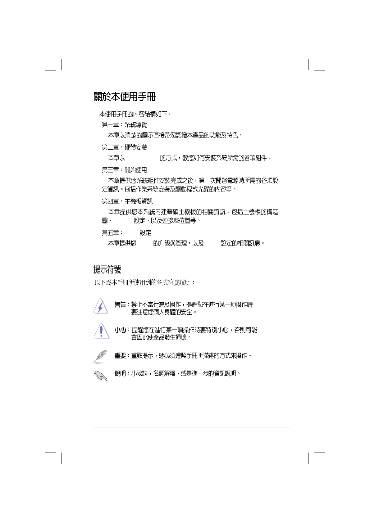
1.
2.
step-by-step
3.
4.
Jumper
5. BIOS
BIOS BIOS
7
Page 8
IC
8
Page 9
Page 10
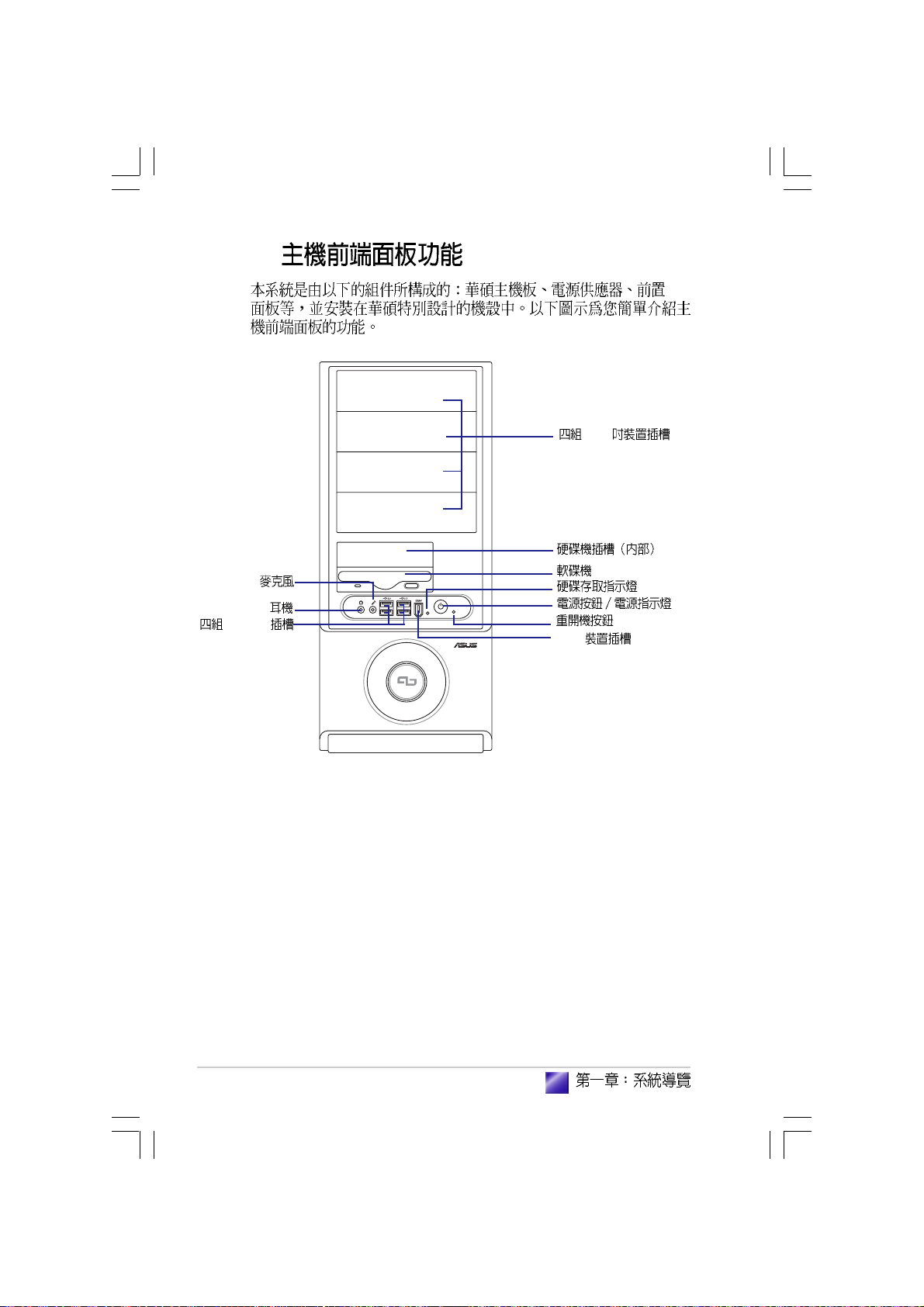
1.1
1.2
1.3
1.4
1.5
...............................................................................
.......................................................................
.......................................................................
...............................................................................
.......................................................................
1-3
1-4
1-5
1-6
1-6
Page 11
1.1
•
•
•
•
•
•
•
•
•
•
1.
2.
1-3
Page 12
1.2
1. Introduction
I/O
5.25
USB 2.0
1394
1-4
Page 13
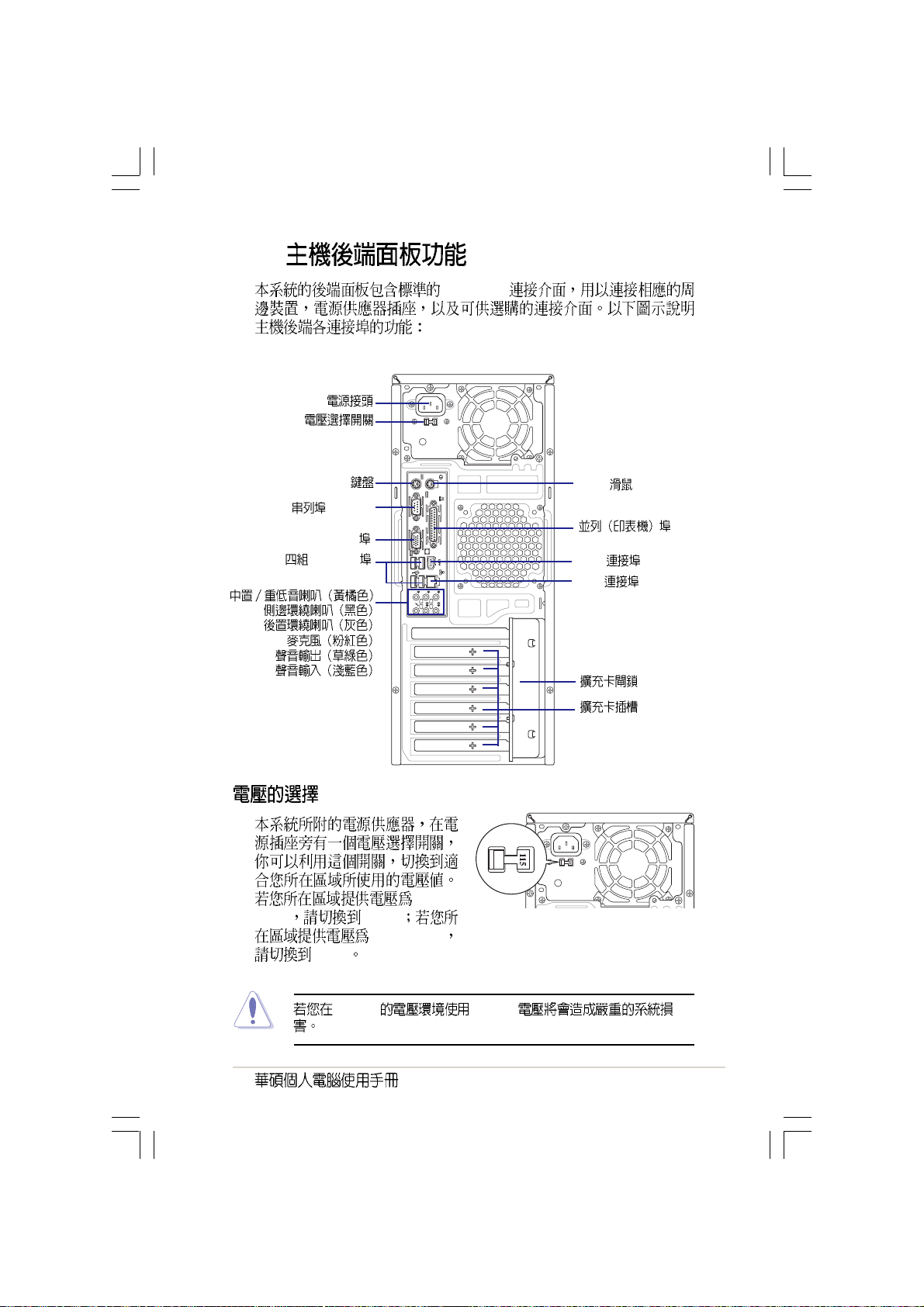
1.3
PC99 I/O
PS/2
(COM1)
VGA
USB 2.0
127V 115V
200-240V
230V
REAR
BASS
S P K
S P K
C T R
SIDE
MIC IN
FRONT
LINE
IN
100-
PS/2
1394
LAN (RJ-45)
230V 115V
1-5
Page 14
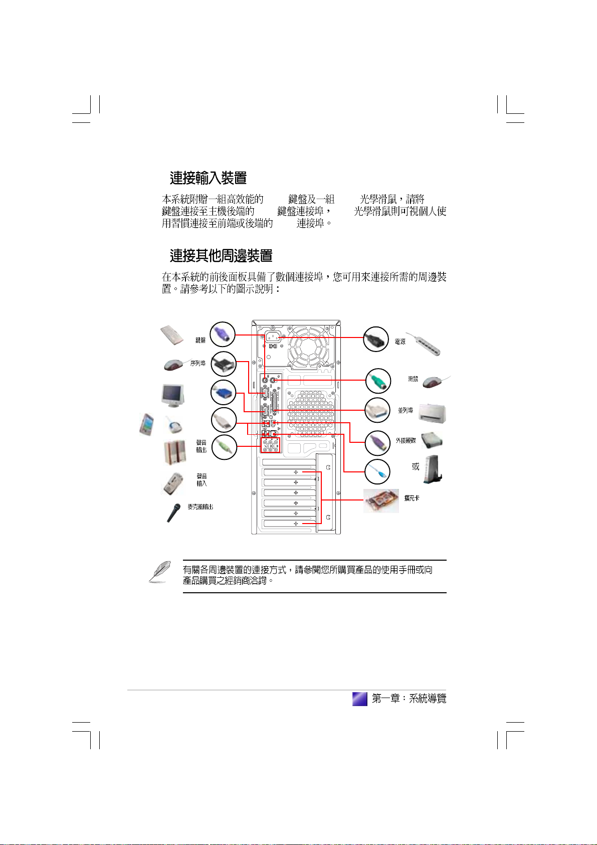
1.4
1.5
PS/2
VGA
USB
PS/2 USB PS/2
PS/2 USB
USB
PS/2
REAR
BASS
S P K
S P K
C T R
SIDE
MIC IN
FRONT
LINE
IN
Hub
Router
1-6
Page 15
step-by-step
Page 16
2.1
2.2 CPU
2.2.1
2.2.2
2.2.3
2.3
2.3.1
2.3.2
2.3.3
2.3.4
2.4
2.4.1
2.4.2
2.5
2.5.1
2.5.2
...................................................................................
.................................................................................
....................................................................................
.....................................................................................
.....................................................................................
2-3
...................................................................
..................................................................
......................................................................
......................................................................
........................................................................
................................................................
................................................................
........................................................................
........................................................................
........................................................................
........................................................................
2-4
2-4
2-7
2-9
2-10
2-10
2-10
2-12
2-12
2-13
2-13
2-14
2-16
2-16
2-17
Page 17
2.1
1.
2.
3.
4.
5. ATX
OFF
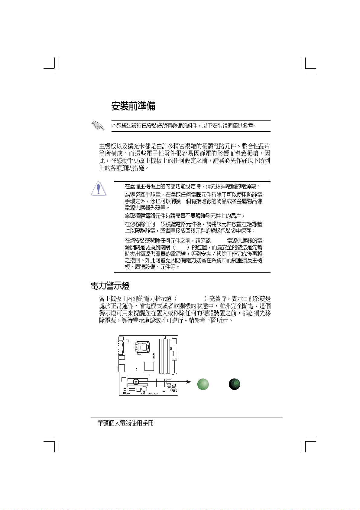
Onboard LED
SB_PWR
®
SB_PWR
ON
Standby
Power
OFF
Powered
Off
2-3
Page 18
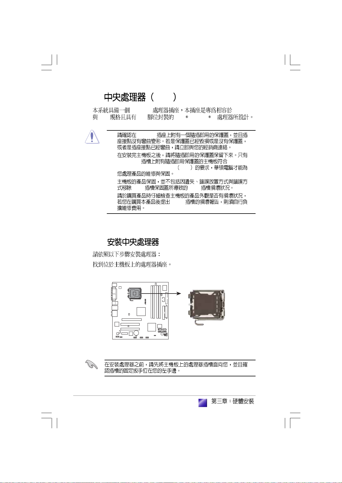
2.2 CPU
LGA775 PCG 04A
04B 775 Intel Pentium 4
2.2.1
1.
•
•
LGA775 Return
Merchandise Authorization RMA
•
•
LGA775
CPU CPU
CPU
®
2-4
CPU Socket 775
Page 19
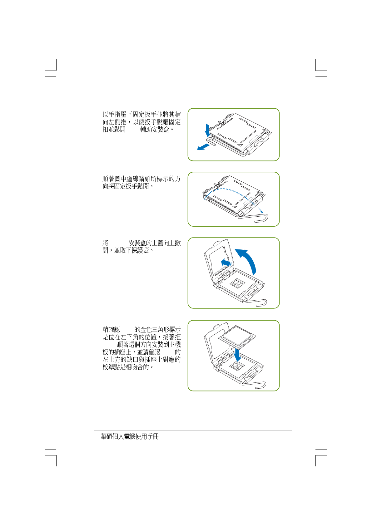
2.
CPU
3.
4. CPU
5. CPU
CPU
CPU
2-5
Page 20
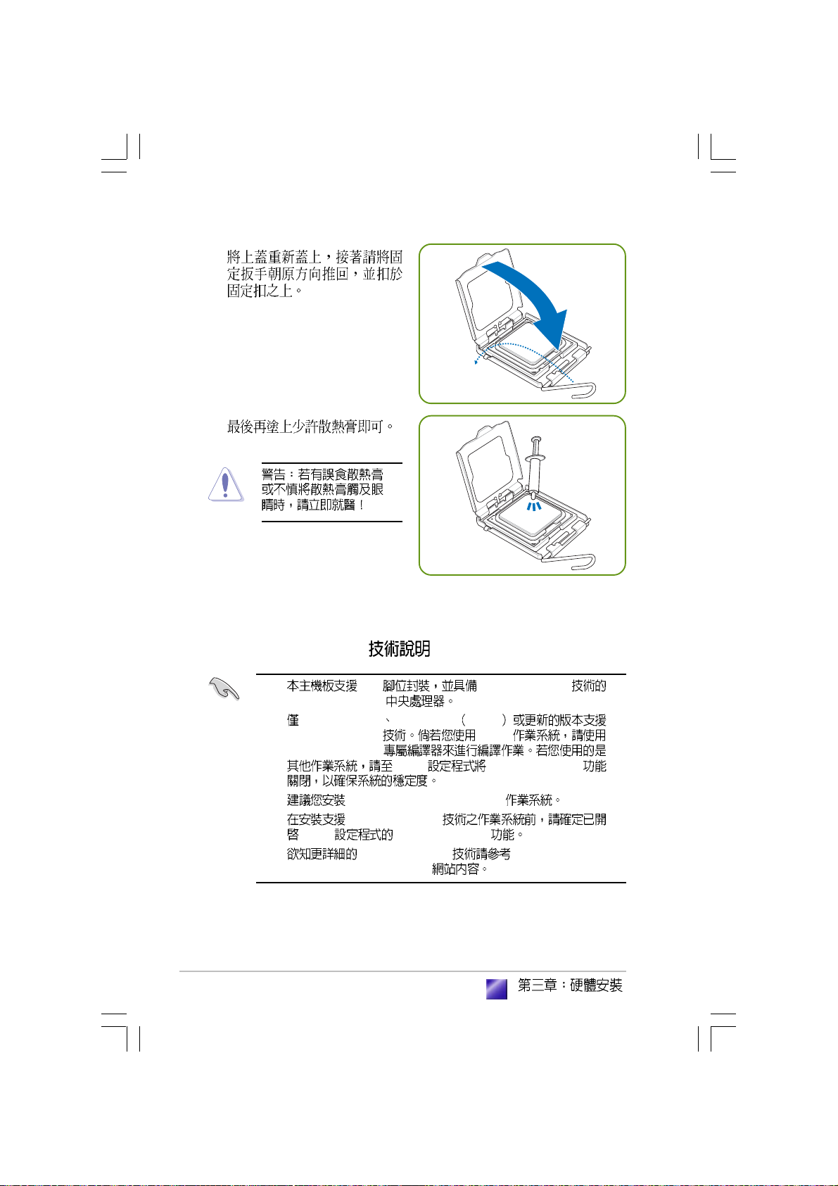
6.
7.
Intel Hyper-Threading
2-6
1. 775 Hyper-Threading
Intel® Pentium® 4
2. Windows® XP Linux 2.4.x kernel
Hyper-Threading Linux
Hyper-Threading
BIOS Hyper-Threading
3. Windows XP Service Pack 2
4. Hyper-Threading
BIOS Hyper-Threading
5. Hyper-Threading http://www.intel.
com/info/hyperthreading
Page 21
Hyper-Threading
1. Hyper-Threading Intel Pentium 4
2. BIOS
Hyper-Threading Technology Enabled
Hyper-Threading CPU
3. BIOS
2.2.2
Intel® Pentium® 4 LGA775
•
•
•
Intel® Pentium® 4 LGA775
CPU
Intel® Pentium® 4 LGA775
CPU Intel
4-pin
®
2-7
Page 22
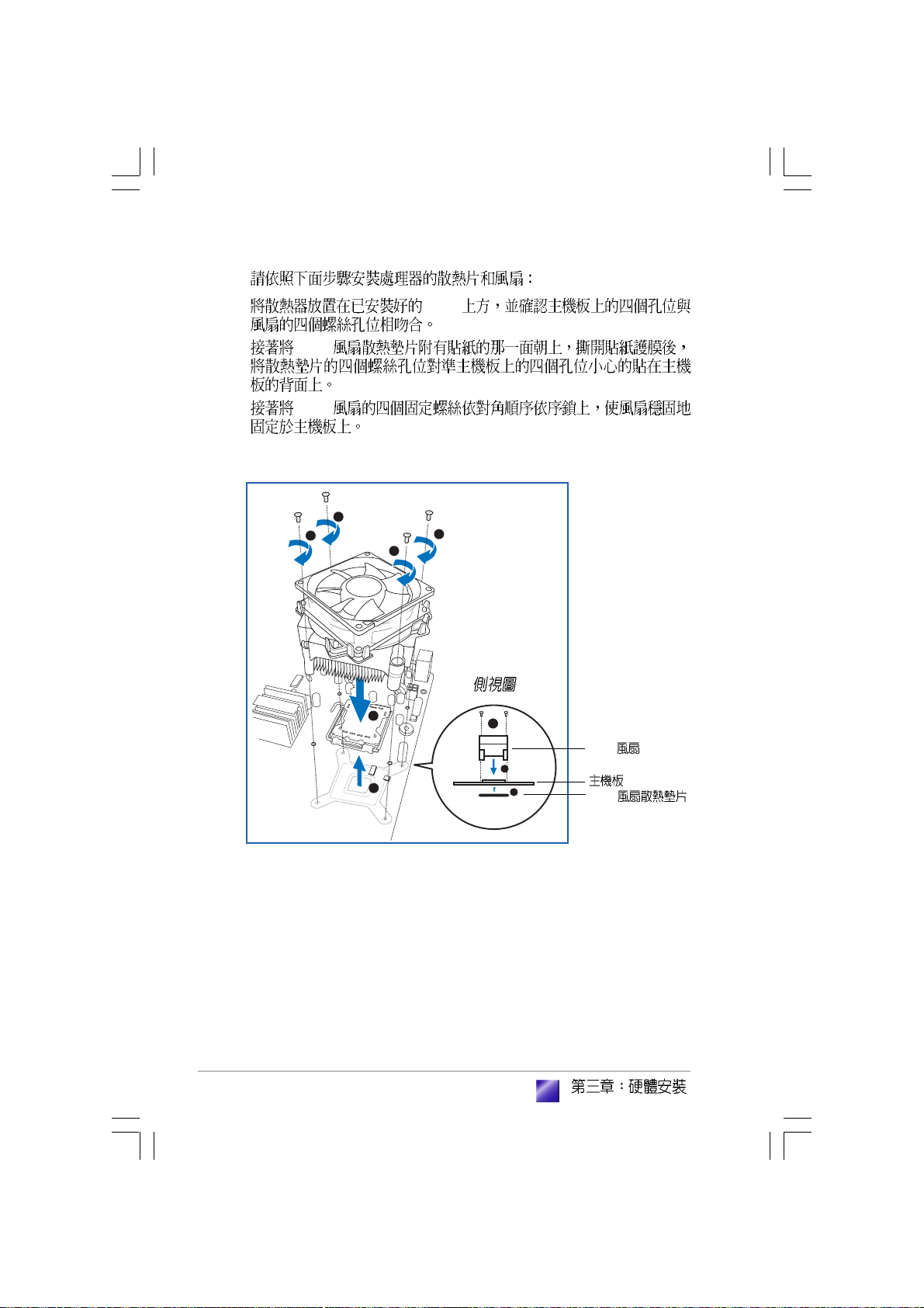
1. CPU
2. CPU
3. CPU
3
3
3
3
2-8
1
3
CPU
1
2
2
CPU
Page 23
4. CPU
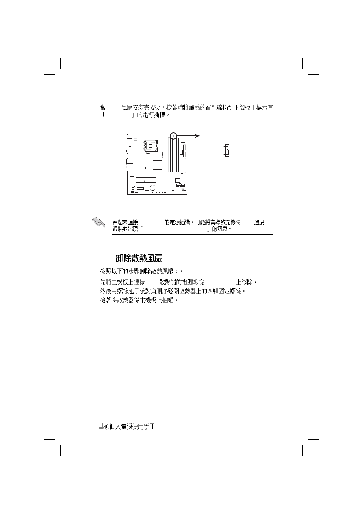
CPU_FAN
CPU_FAN
CPU FAN PWM
®
CPU fan connector
CPU FAN IN
CPU FAN PWR
GND
CPU_FAN CPU
Hardware monitoring errors
2.2.3
1. CPU CPU_FAN1
2.
3.
2-9
Page 24
2.3
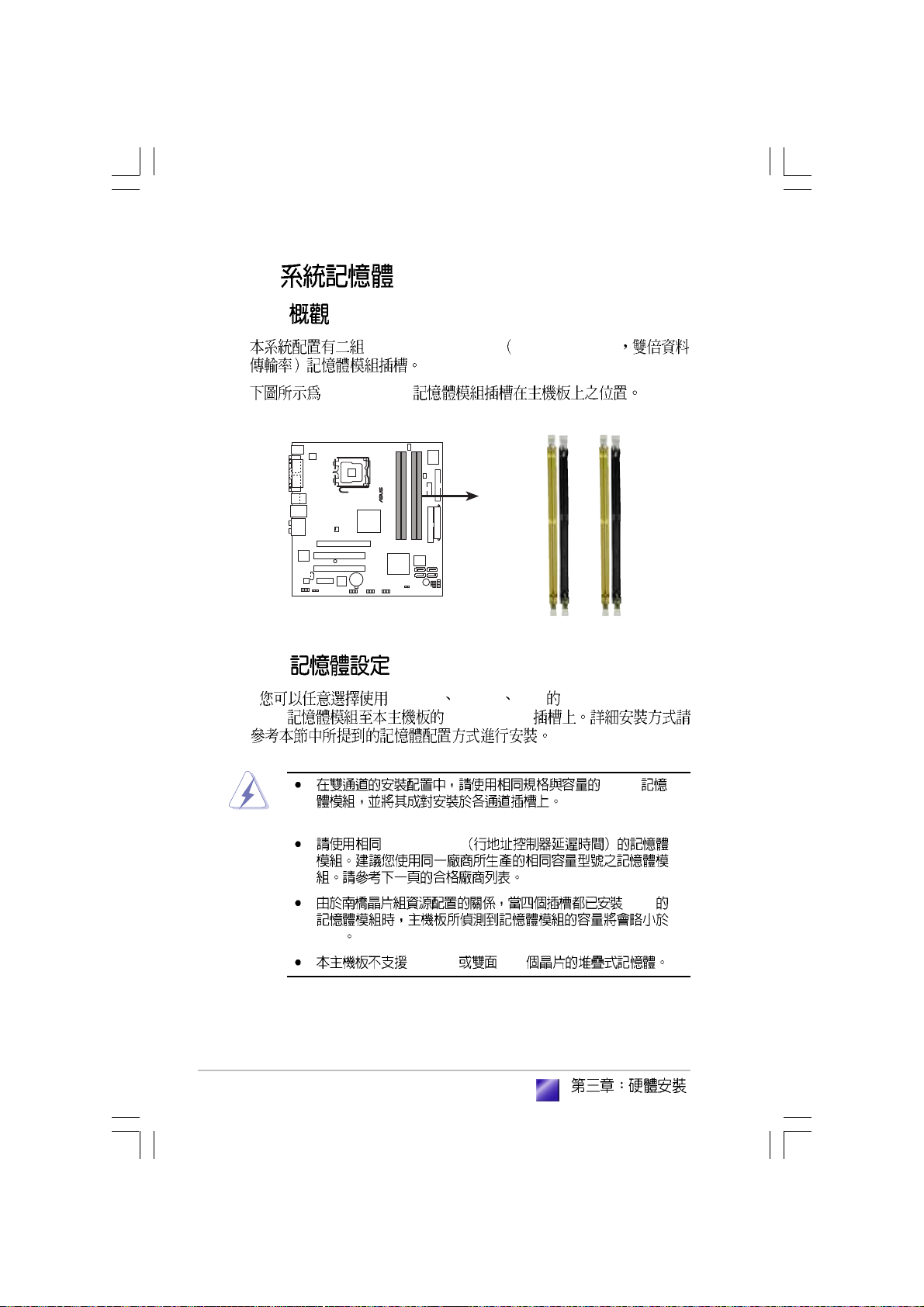
2.3.1
240-pin DDR2 DIMM Double Data Rate
DDR2 DIMM
®
240-pin DDR2 DIMM sockets
2.3.2
256MB 512MB 1GB unbuffered non-ECC
DDR DDR DIMM
DIMM_A1
DIMM_A2
DIMM_B1
DIMM_B2
2-10
DDR2
(DIMM_A1+DIMM_A2 = DIMM_B1+DIMM_B2).
CAS latency
1 GB
4GB
128 Mb x16
Page 25
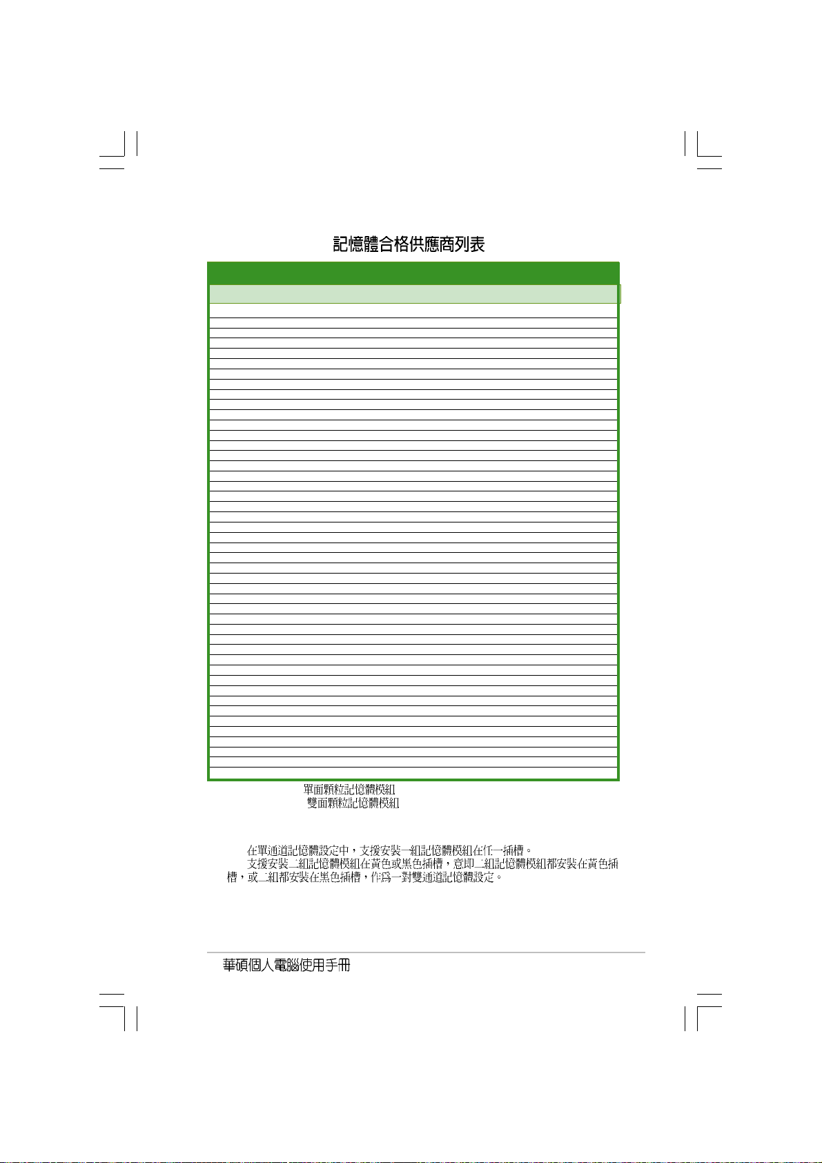
DDR2 (533 MHz)
(optional) (optional)
(optional)
(optional) (optional)
SizeSize
VendorVendor
Size
Vendor
SizeSize
VendorVendor
512MB SAMSUNG M378T6553BG0-CD5 N/A SS K4T51083QB-GCD5 N/A V V V
1024MB SAMSUNG M378T2953BG0-CD5 N/A DS K4T51083QB-GCD5 4 V V V
256MB SAMSUNG M378T3253FG0-CD5 N/A SS K4T56083QF-GCD5 4 V V V
512MB SAMSUNG M378T6453FG0-CD5 N/A DS K4T56083QF-GCD5 4 V V V
512MB Infineon HYS64T64000GU-3.7-A Infineon SS HYB18T512800AC37 4 V V V
256MB Infineon HYS64T32000HU-3.7-A Infineon SS HYB18T512160AF-3.7 4 V V V
1024MB Infineon HYS64T128020HU-3.7-A Infineon DS HYB18T512800AF37 4 V V V
512MB Infineon HYS64T64000HU-3.7-A Infineon SS HYB18T512800AF37 N/A V V V
512MB CORSAIR CM2X512-4200 N/A DS N/A 4 V V V
512MB MICRON MT16HTF6464AG-53EB2 MICRON DS 4FBIID9BQM 4 V V V
256MB MICRON MT8HTF3264AY-53EB3 MICRON SS 4FBIID9CHM 4 V V V
512MB MICRON MT16HTF6464AY-53EB2 MICRON DS 4FBIID9CHM 4 V V V
256MB Kingston KVR533D2N4/256 ELPIDA SS E5116AB-5C-E N/A V V V
512MB Kingston KVR533D2N4/512 N/A DS HY5PS56821F-C4 N/A V V V
1024MB Kingston KVR533D2N4/1G N/A DS D6408TE7BL-37 N/A V V V
512MB Hynix HYMP564U648-C4 N/A SS HY5PS12821F-C4 4 V V V
1024MB Hynix HYMP512U648-C4 N/A DS HY5PS12821F-C4 4 V V V
512MB Hynix HYMP564U64AP8-C3 N/A SS HY5PS12821AFP-C3 3 V V V
1024MB Hynix HYMP512U64AP8-C3 N/A DS HY5PS12821AFP-C3 3 V V V
512MB ELPIDA EBE51UD8ABFA-5C ELPIDA DS E5108AB-5C-E N/A V V V
512MB ELPIDA EBE51UD8ABFA-5C-E ELPIDA DS E5108AB-5C-E N/A V V V
256MB KINGMAX KLBB68K-38SP4 N/A SS K4T56083QF-GCD5 N/A V V
1024MB KINGMAX KLBD48F-A8EP4 N/A DS E5108AB-5C-E N/A V
512MB KINGMAX KLBC28F-A8EP4 N/A SS E5108AB-5C-E N/A V V V
256MB KINGMAX KLBB68F-38KP4 KINGMAX SS KKE388A4IA-37 N/A V
512MB KINGMAX KLBC28F-A8KP4 KINGMAX SS KKEA88A4IA-37 N/A V V V
1024MB KINGMAX KLBD48F-A8KP4 KINGMAX DS KKEA88A4IA-37 N/A V V
512MB TwinMOS 8D-22JB5-K2T N/A SS K4T51083QB-GCD5 N/A V V V
256MB Apacer 78.81067.460 N/A SS K4T56083QF-GCD5 4 V V V
512MB Apacer 78.91066.420 N/A SS E5108AB-5C-E 4 V V V
1024MB Apacer 78.01066.420 N/A DS E5108AB-5C-E 4 V V
256MB NANYA NT256T64UH4A0F-37B NANYA SS NT5TU32M16AF-37B 4 V V V
512MB NANYA NT512T64U88A0F-37B NANYA SS NT5TU64M8AF-37B 4 V V V
1024MB NANYA NT1GT64U8HA0F-37B NANYA DS NT5TU64M8AF-37B 4 V V V
256MB elixir M2U25664TUH4A0F-37B N/A SS N2TU51216AF-37B 4 V V V
512MB elixir M2U51264TU88A0F-37B N/A SS N2TU51280AF-37B 4 V V V
256MB crucial BL3264AA53V.8FB Ballistix SS N/A 3 V V
512MB crucial BL6464AA53V.16FB Ballistix DS N/A 3 V V
256MB CENTURY 25V6S8SSD5F4-K43 N/A SS K4T56083QF-GCD5 4 V V V
512MB CENTURY 25V2H8EL5CB4-J43 N/A SS E5108AB-5C-E 4 V V V
1024MB CENTURY 25V0H8EL5CB4-J45 N/A DS E5108AB-5C-E 4 V V V
256MB Aeneon AET560UD00-370A98X Aeneon SS AET960UD00-37C88X N/A V V V
512MB Aeneon AET660UD00-370A98X Aeneon DS AET960UD00-37C88X N/A V V
512MB Aeneon AET660UD00-370A98X Aeneon SS AET93F-370AG0513 N/A V V
512MB Transcend TS64MLQ64V5J N/A SS K4T51083QB-GCD5 4 V V V
1024MB Transcend TS128MLQ64V5J N/A DS K4T51083QB-GCD5 N/A V
ModelModel
Model
ModelModel
BrandBrand
Brand
BrandBrand
Side(s)Side(s)
Side(s)
Side(s)Side(s)
ComponentComponent
Component
ComponentComponent
SS -Single-sided
DS -Double-sided
CL-CAS Latency
DIMM support:
A B -
DIMM support DIMM support
DIMM support
DIMM support DIMM support
CLCL
AA
CL
A
CLCL
AA
BB
CC
B
C
BB
CC
2-11
Page 26
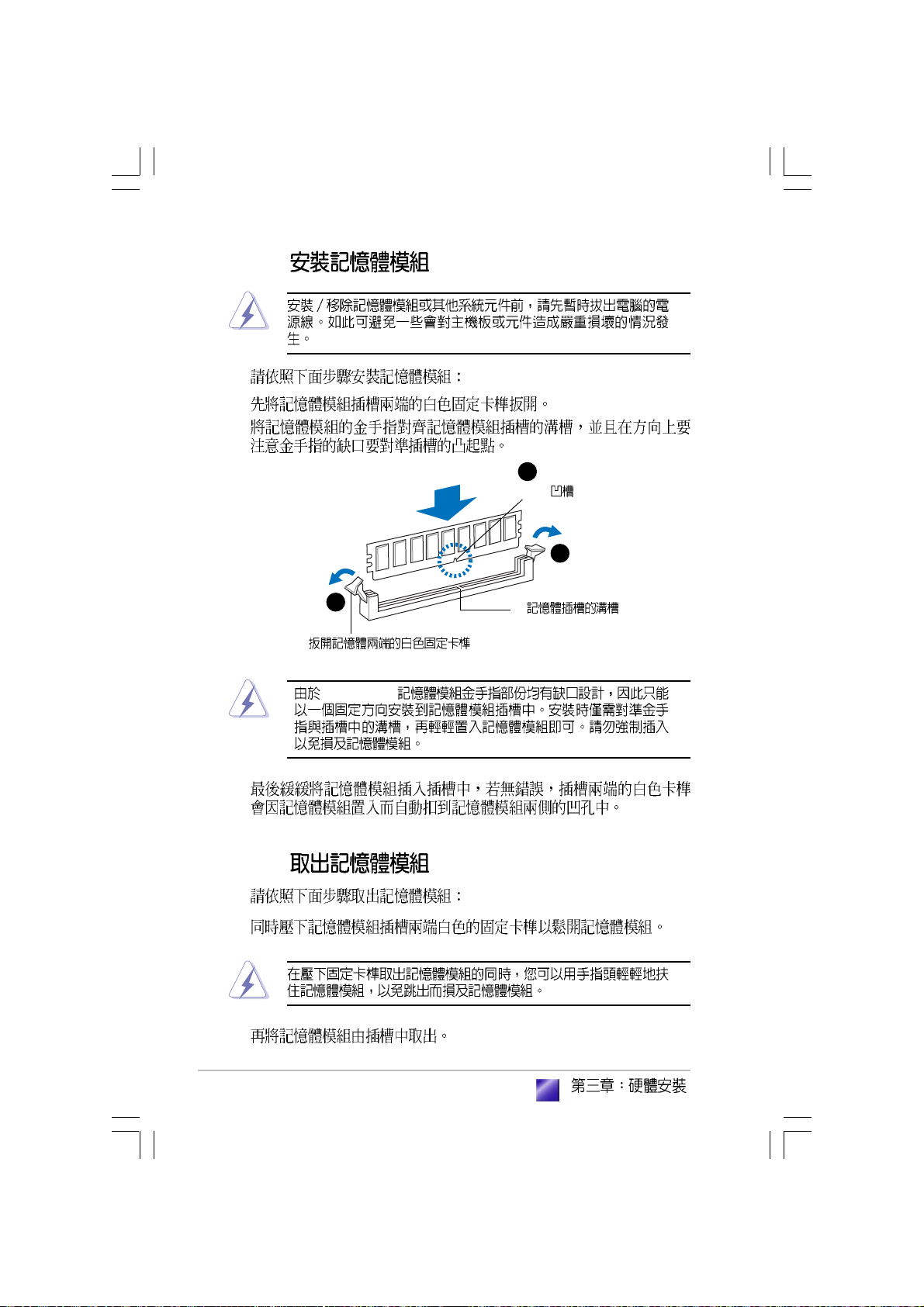
2.3.3
1.
2.
2
DIMM
1
1
DDR DIMM
2-12
3.
2.3.4
1.
2.
Page 27
2.4
2.4.1
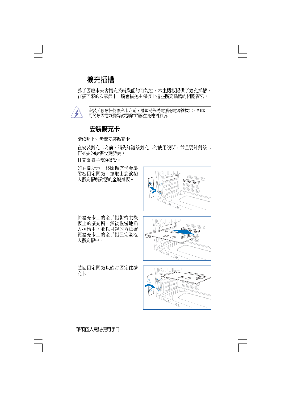
1.
2.
3.
4.
5.
2-13
Page 28
2.4.2
1. BIOS
BIOS
2. IRQ
3.
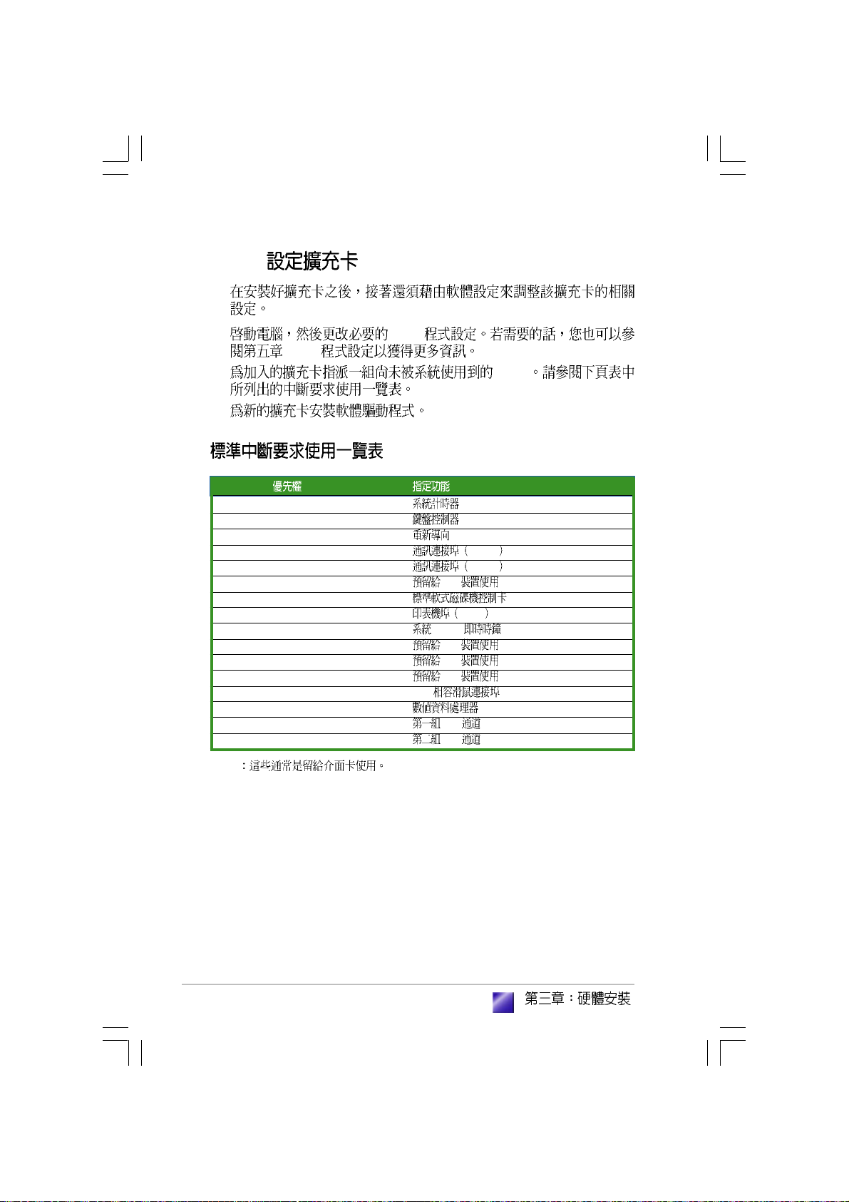
IRQ
01
12
2 N/A IRQ#9
311 COM 2 *
412 COM 1 *
513 PCI *
614
715 LPT 1 *
83 CMOS/
94 PCI *
10 5 PCI *
11 6 PCI *
12 7 PS/2 *
13 8
14 9 IDE
15 10 IDE
2-14
*
Page 29
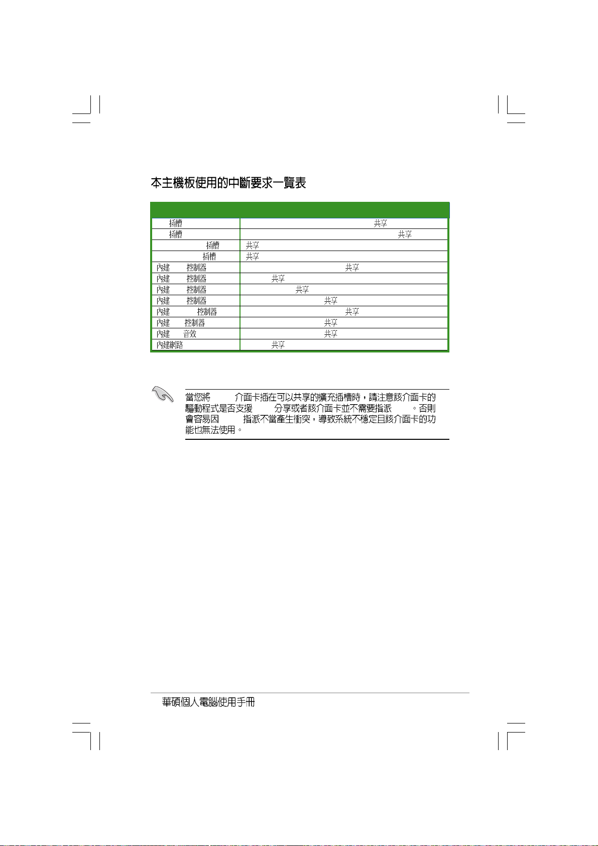
ABCDEFGH
PCI 1------PCI 2------PCI Express X16 -- -- --PCI Express X1 -- -- ---
USB 1---- -- USB 2- ----- USB 3-- -- - - USB 4--- --- USB 2.0 --- - -- IDE --- --- HD --- ----
- ------
PCI
IRQ IRQ
IRQ
2-15
Page 30

2.5
2.5.1
1.
2.
3.
4. IDE (A)
- Serial ATA
(B)
A B
2
2
1
SATA
2-16
IDE
Serial ATA
IDE
Page 31

2.5.2
RW
CD-ROM/CD-RW/DVD-ROM/DVD-
2
3
1.
2. 5.25
3.
4. IDE
3
IDE
2-17
Page 32

2-18
Page 33

Page 34

3.1
3.2
3.3
3.3.1
3.3.2 Drivers Menu
3.3.3 Utilities Menu
3.3.4 Manual Menu
3.3.5
3.4 Recovery CD
...............................................................................
.......................................................................................
..................................................................
3-3
3-3
...................................................
..........................................
...............................
..............................
.......................................
.................................................
3-4
3-4
3-5
3-6
3-8
3-8
3-9
Page 35

3.1
3.2
Windows 2000/XP
3-3
Page 36

3.3
3.3.1
http://tw.asus.com
3-4
BIN ASSETUP.EXE
Page 37

3.3.2 Drivers Menu
ASUS InstAll
ASUS
QFE
Quick Fix Engineering QFE
Intel Chipset Inf Update
Intel(R)
Realtek
Intel Chipset Inf Update
interactive silent unattended preload
interactive
silent unattended preload
Readme
Intel Graphics Media Accelerator 950
Realtek ALC861
3-5
Page 38

Intel(R) Tekoa
Intel(R) Tekoa
USB 2.0
USB 2.0
3.3.3 Utilities menu
ASUS InstAll
3-6
ASUS
II ASUS PC Probe II
Page 39

ASUS Live Update
BIOS
MyLogoTM
Adobe Acrobat Reader V7.0
Adobe Acrobat Reader V7.0 PDF Portable
Document Format
DirectX 9.0c
DirectX 9.0c
3-7
Page 40

3.3.4 Manual Menu
PDF
Reader
3.3.5
Adobe Acrobat
3-8
Page 41

3.4
1. MS-DOS with CD-ROM Support.
2. Recover Windows XP to first partition only.
3. Recover Windows XP to entire HD.
2 <Enter>
<A> <C>
<A>
<Y> <N>
<N> <Y>
Recovery CD
Recovery CD
BIOS <ESC>
<Y>
CD Support CD
Windows XP
Support
http://tw.asus.com
3-9
Page 42

3-10
Page 43

Jumper
BIOS
<Del> BIOS
( )
Page 44

4.1
4.2
4.3
4.4
...............................................................................................
...............................................................................
...................................................................................
...............................................................
4.4.1
4.4.2
..................................................................
..............................................................
4-3
4-3
4-4
4-5
4-5
4-7
Page 45

4.1
4.2
PS/2KBMS
T: Mouse
B: Keyboard
COM1
VGA
Bottom:
Top:
USB1
1394
USB2
LAN_USB34
AUDIO
Intel
82573L
PARALLEL PORT
AAFP
ALC882
ATX12V
CD
PCIEX1_1
SPDIF_OUT
CHA_FAN
LGA775
PCIEX16
PCI1
SB_PWR
PCI2
TI
TSB43AB22A
CR2032 3V
Lithium Cell
CMOS Power
IE1394_2
Intel
GMCH
945G
USB56
CPU_FAN
I/O
Super
PWR_FAN
FLOPPY
®
COM2
®
DDR DIMM_A1 (64 bit,240-pin module)
DDR DIMM_A2 (64 bit,240-pin module)
DDR DIMM_B1 (64 bit,240-pin module)
DDR DIMM_B2 (64 bit,240-pin module)
EATXPWR
PRI_IDE
Intel FWH
USB78
Intel
ICH7
®
CLRTC
4Mb
PLED
SATA4SATA3
SATA1 SATA2
BUZZ
CHASSIS
SPEAKER
F_PANEL
4-3
Page 46

4.3
1. CMOS CLRTC
CMOS
CMOS
1
2 CLRTC [1-2] [2-3]
CMOS [1-2]
3
4 Del BIOS
BIOS
CMOS
®
4-4
CLRTC
12 23
Clear RTC RAM
Normal ClearCMOS
(Default)
CMOS C.P.R. CPU
BIOS
Page 47

4.4
4.4.1
1
15
1. PS/2 PS/2
2.
3. 1394 1394 1394
4. RJ-45 LAN
Local Area Network
5.
6.
7.
8.
14 13
2 4
/
3
12
11
65 7 8
9
10
9.
10.
4-5
Page 48

11.USB 2.0 3 4 USB
USB 2.0
12.USB 2.0 1 2 USB
USB 2.0
13. VGA VGA VGA
14. 9-pin COM1
15. PS/2 PS/2
4-6
Page 49

4.4.2
1. IDE 40-1 pin PRI_IDE
IDE IDE IDE
CD-ROM
IDE
Slave UltraATA133 IDE
UltraATA133 IDE
1. IDE
Master
Slave
2. IDE UltraDMA
3. UltraATA
Master
IDE connector
®
PRI_IDE
NOTE: Orient the red markings
(usually zigzag) on the IDE
ribbon cable to PIN 1.
PIN 1
Pin 1
4-7
Page 50

2. 24-pin EATXPWR, 4-pin ATX12V
ATX 12V
24 ATXPWR
+12V
EATXPWR
®
ATX12V
+12V DC
GND
GND
+12V DC
ATX power connectors
1. ATX 12V 2.0 300
24-pin 4-pin ATX
2. 20-pin 4-pin 20-pin
+12V 15
300
+3 Volts
+12 Volts
+12 Volts
+5V Standby
Power OK
Ground
+5 Volts
Ground
+5 Volts
Ground
+3 Volts
+3 Volts
Ground
+5 Volts
+5 Volts
+5 Volts
-5 Volts
Ground
Ground
Ground
PSON#
Ground
-12 Volts
+3 Volts
3. 34-1 pin FLOPPY
®
Floppy disk drive connector
4-8
FLOPPY
NOTE: Orient the red markings on
the floppy ribbon cable to PIN 1.
PIN 1
Pin 1
Page 51

4. 4-pin CPU_FAN,
3-pin PWR_FAN, 3-pin CHA_FAN
350 740 8.88 1 2.
22 26.64 +12
+12V
GND
CPU_FAN
CPU FAN PWM
CPU FAN IN
®
Fan connectors
CPU FAN PWR
GND
PWR_FAN
GND
+12V
Rotation
CHA_FAN
GND
+12V
Rotation
5. 1394 10-1 pin IE1394_2
I/O 1394
1394
®
IEEE 1394 connector
IE1394_2
GND
+12V
+12V
TPB2+
GND
GND
TPB2-
TPA2+
1
TPA2-
4-9
Page 52

6. USB 10-1 pin USB56, USB78
I/O USB 2.0
USB
®
USB+5V
USB_P6-
USB_P6+
USB56
1
USB+5V
USB_P5-
USB 2.0 connectors
USB_P5+
7. 4-pin CD
GND
GND
NC
USB78
MPEG
1
USB+5V
USB_P8-
USB_P8+
USB+5V
USB_P7-
USB_P7+
GND
GND
NC
4-10
®
CD audio connector
CD
Right Audio Channel
Ground
Ground
Left Audio Channel
Page 53

8. 10-1 AAFP
LINE OUT_R/BLINE_OUT_R
LINE OUT_L/BLINE_OUT_L
®
Analog front panel connector
Azalia
compliant definition
SENSE1_RETUR
PRESENCE#
GND
PORT1 L
PORT2 R
PORT1 R
9. 4-1 pin CHASSIS
AAFP
SENSE2_RETUR
PORT2 L
SENSE_SEND
Legacy AC’97
compliant definition
BLINE_OUT_L
+5VA
BLINE_OUT_R
AGND
NC
MIC2
MICPWR
Line out_L
Line out_R
Signal GND
Chassis Signal GND
®
Chassis intrusion connector
CHASIS Chassis
CHASSIS
GND
Chassis Signal
+5VSB_MB
(Default)
4-11
Page 54

10. Serial ATA RAID 7-pin SATA1, SATA2,
SATA3, SATA4
Serial ATA Serial
ATA 150MB
133MB Parallel ATA UltraATA 133
®
RSATA_RXP3
GND
RSATA_TXP3
GND
GND
RSATA_RXN3
RSATA_TXN3
SATA3 SATA4
SATA1 SATA2
GND
GND
SATA connectors
RSATA_TXP1
RSATA_TXN1
RSATA_RXP1
GND
RSATA_RXN1
11. 4-1 pin SPDIF_OUT
S/PDIF S/
PDIF
®
SPDIF_OUT
SPDIFOUT
GND
+5V
RSATA_RXP4
GND
RSATA_TXP4
GND
GND
RSATA_RXN4
RSATA_TXN4
GND
GND
GND
RSATA_TXP2
RSATA_TXN2
RSATA_RXP2
RSATA_RXN2
4-12
Digital audio connector
Page 55

12. COM2 10-1 pin COM2
BIOS
COM2 COM2
COM2 COM2
®
COM2
PIN 1
Serial port connector
13. 3-1 pin PLED
®
PLED
PLEDNC
PLED+
1
Power LED connector
4-13
Page 56

14. 10-1 pin F_PANEL
®
F_PANEL
PWRSW
PWRLED
GND Reset
PWR Ground
PWR_LEDPWR_LED+
* Requires an ATX power supply.
System panel connector
2-pin RESET
Reset
ATX / 2-pin PWRSW
BIOS
IDE_LEDIDE_LED+
RESET
IDE LED
4-14
IDE 2-pin IDE LED
IDE LED IDE
IDE
2-pin PWRLED
Page 57

BIOS
( )
BIOS
BIOS
BIOS
<Del> BIOS
Page 58

5.1 BIOS
5.2 BIOS
5.3 Main menu
5.4 Advanced menu
5.5 Power menu
5.6 Boot menu
5.7 BIOS Exit menu
...........................................................................
...............................................................
.........................................................
............................................................
........................................................
...................................................
..................................................
5-3
5-13
5-16
5-21
5-31
5-35
5-39
Page 59

5.1 BIOS
BIOS Basic Input/Output
System
1. ASUS AFUDOS DOS BIOS
2. ASUS EZ Flash POST BIOS
3. ASUS CrashFree BIOS 2 BIOS
BIOS
4. ASUS Update Windows BIOS
BIOS
BIOS AFUDOS
BIOS
5.1.1
1.
DOS
a. 1.44MB
b. DOS format A:/S Enter
Windows XP
a. 1.44MB
b. Windows
c. 3 1/2
d. File Format Format 3 1/
2 Floppy Disk
e. Create a MS-DOS startup disk
Windows 2000
a. 1.44MB
b. Windows 2000
c. Run
d. D:\bootdisk\makeboot a:
D
e. Enter
2. BIOS
5-3
Page 60

5.1.2 AFUDOS BIOS
AFUDOS DOS BIOS
BIOS AFUDOS BIOS
BIOS
BIOS
BIOS
600KB
BIOS
1. AFUDOS afudos.
exe
2. DOS
filename
A:\>afudos /oOLDBIOS1.ROM
3. Enter BIOS
A:\>afudos /oOLDBIOS1.ROM
AMI Firmware Update Utility - Version 1.10
Copyright (C) 2002 American Megatrends, Inc. All rights reserved.
Reading flash ..... done
A:\>
BIOS DOS
5-4
BIOS
Page 61

BIOS
AFUDOS BIOS
1. tw.asus.com BIOS
BIOS
BIOS
2. AFUDOS.EXE BIOS
3. DOS
filename
BIOS
A:\>afudos /iP5LD2VM.ROM
4. AFUDOS BIOS
A:\>afudos /iP5LD2VM.ROM
AMI Firmware Update Utility - Version 1.10
Copyright (C) 2002 American Megatrends, Inc. All rights reserved.
Reading file ..... done
Erasing flash .... done
Writing flash .... 0x0008CC00 (9%)
BIOS
5. BIOS DOS
A:\>afudos /iP5LD2VM.ROM
AMI Firmware Update Utility - Version 1.10
Copyright (C) 2002 American Megatrends, Inc. All rights reserved.
Reading file ..... done
Erasing flash .... done
Writing flash .... 0x0008CC00 (9%)
Verifying flash .. done
A:\>
5-5
Page 62

5.1.3 EZ Flash BIOS
EZ Flash BIOS
DOS EZ Flash BIOS
Power-On Self
Test POST Alt + F2 EZ Flash
EZ Flash BIOS
1. tw.asus.com BIOS
P5LD2-VM.ROM
2.
3. POST Alt + F2
EZ Flash
EZFlash starting BIOS update
Checking for floppy...
4. BIOS
EZ Flash BIOS
EZFlash starting BIOS update
Checking for floppy...
Floppy found!
Reading file “P5LD2VM.ROM”. Completed.
Start erasing.......|
Start Programming...|
Flashed successfully. Rebooting.
5-6
BIOS
Page 63

BIOS
Floppy not found BIOS
P5LD2-VM.ROM not
found BIOS
P5LD2-VM.ROM
5-7
Page 64

5.1.4 CrashFree BIOS 2 BIOS
CrashFree BIOS 2 BIOS
BIOS BIOS
1. BIOS
BIOS
2. BIOS P5LD2-VM.
ROM
BIOS
BIOS
1.
2. BIOS
3.
BIOS
Bad BIOS checksum. Starting BIOS recovery...
Checking for floppy...
5-8
BIOS
Bad BIOS checksum. Starting BIOS recovery...
Checking for floppy...
Floppy found!
Reading file “P5LD2VM.ROM”. Completed.
Start flashing...
BIOS
4.
BIOS
Page 65

BIOS
BIOS
1.
2.
3.
BIOS
Bad BIOS checksum. Starting BIOS recovery...
Checking for floppy...
Bad BIOS checksum. Starting BIOS recovery...
Checking for floppy...
Floppy not found!
Checking for CD-ROM...
CD-ROM found.
Reading file “P5LD2VM.ROM”. Completed.
Start flashing...
BIOS
4. BIOS
BIOS http://tw.asus.com
BIOS
BIOS
5-9
Page 66

5.1.5
Windows
BIOS
1. BIOS
2. BIOS
3. BIOS BIOS
4. BIOS
5. BIOS
ISP
1.
2. VX.XX.
XX
3.
5-10
BIOS
BIOS
Page 67

BIOS
BIOS
1. ASUS ASUSUpdate ASUSUpdate
2. Update
BIOS from the Internet
Next
3. FTP
Auto Select
Next
5-11
Page 68

4. BIOS
Next
5.
BIOS
BIOS
BIOS BIOS
BIOS BIOS
1. ASUS
ASUSUpdate ASUSUpdate
2. Update BIOS
from a file Next
3. BIOS
4.
BIOS
5-12
BIOS
Page 69

5.2 BIOS
BIOS Basic Input and Output System
BIOS
BIOS
RUN SETUP BIOS
BIOS
Flash ROM BIOS Flash
ROM
BIOS BIOS
BIOS
CMOS RAM
POST Power-On Self Test
DELETE
DELETE
RESET Ctrl + Alt + Delete
BIOS
BIOS
BIOS
1. BIOS
BIOS
2.7 BIOS Load Setup
Defaults
2. BIOS
3. http://tw.asus.com BIOS
BIOS
5-13
Page 70

5.2.1 BIOS
System Time [11:51:19]
System Date [Thu 06/10/2004] Legacy
Diskette A [1.44M, 3.5 in]
Primary IDE Master : [ST320413A]
Primary IDE Slave : [Pioneer CD-ROM ATA]
Third IDE Master : [Not Detected]
Third IDE Slave : [Not Detected]
Fourth IDE Master : [Not Detected]
Fourth IDE Slave : [Not Detected]
IDE Configuration
System Information
5.2.2
BIOS
BIOS
Use [ENTER], [TAB] or
[SHIFT-TAB] to select
a field.
Use [+] or [-] to
configure the System
time.
5-14
5.2.3
BIOS
Page 71

5.2.4
Exit
5.2.5
5.2.6
Advanced Power Boot
System Time [11:51:19]
System Date [Thu 06/10/2004]
Legacy Diskette A [1.44M, 3.5 in]
Primary IDE Master : [ST320413A]
Primary IDE Slave : [Pioneer CD-ROM ATA]
Third IDE Master : [Not Detected]
Third IDE Slave : [Not Detected]
Fourth IDE Master : [Not Detected]
Fourth IDE Slave : [Not Detected]
IDE Configuration
System Information
Enter
Advanced PCI/PnP Settings
WARNING: Setting wrong values in
below sections may cause system to
malfunction.
Plug And Play O/S [No]
PCI Latency Timer [64]
Allocate IRQ to PCI VGA [Yes]
Palette Snooping [Disabled]
PCI IDE BusMaster [Enabled]
Use [ENTER], [TAB]
or [SHIFT-TAB] to
select a field.
Use [+] or [-] to
configure the
System time.
5.2.7
5.2.8
5.2.9
Enter
5-15
Page 72

5.3 Main Menu
BIOS
5.2.1 BIOS
System Time [11:51:19]
System Date [Thu 06/10/2004] Legacy
Diskette A [1.44M, 3.5 in]
Primary IDE Master : [ST320413A]
Primary IDE Slave : [Pioneer CD-ROM ATA]
Third IDE Master : [Not Detected]
Third IDE Slave : [Not Detected]
Fourth IDE Master : [Not Detected]
Fourth IDE Slave : [Not Detected]
IDE Configuration
System Information
Use [ENTER], [TAB] or
[SHIFT-TAB] to select
a field.
Use [+] or [-] to
configure the System
time.
5.3.1 System Time [XX:XX:XX]
00 23 00 59 00 59
Tab Tab + Shift
5.3.2 System Date [Day XX/XX/XXXX]
1 12 1 31 2099 Tab
Tab + Shift
5.3.3 Legacy Diskette A [1.44M, 3.5 in.]
[Disabled] [360K, 5.25
in.] [1.2M, 5.25 in.] [720K, 3.5 in.] [1.44M, 3.5 in.] [2.88M, 3.5 in.]
5-16
BIOS
Page 73

5.3.4 IDE Primary, Third and Fourth
IDE Master/Slave
BIOS IDE
IDE Enter
Primary IDE Master
Device : Hard Disk
Vendor : ST320413A
Size : 20.0GB
LBA Mode : Supported
Block Mode : 16 Sectors
PIO Mode : Supported
Async DMA : MultiWord DMA-2
Ultra DMA : Ultra DMA-5
SMART Monitoring : Supported
Type [Auto]
LBA/Large Mode [Auto]
Block(Multi-sector Transfer) [Auto]
PIO Mode [Auto]
Smart Monitoring [Auto]
32Bit Data Transfer [Disabled]
Select the type of
device connected to
the system.
Device Vendor Size LBA Mode Block
Mode PIO Mode Async DMA Ultra DMA SMART monitoring
BIOS N/A
Type [Auto]
IDE Auto
IDE CDROM IDE
ARMD ATAPI
IDE ZIP LS-120 MO
[Not Installed] [Auto] [CDROM] [ARMD]
LBA/Large Mode [Auto]
LBA [Auto]
LBA LBA
[Disabled] [Auto]
Block (Multi-sector Transfer) [Auto]
[Disabled]
[Disabled] [Auto]
[Auto]
5-17
Page 74

PIO Mode [Auto]
PIO [Auto] [0] [1] [2] [3] [4]
DMA Mode [Auto]
DMA [Auto] [SWDMA0] [SWDMA1] [SWDMA2]
[MWDMA0] [MWDMA1] [MWDMA2] [UDMA0] [UDMA1] [UDMA2]
[UDMA3] [UDMA4] [UDMA5] [UDMA6]
SMART Monitoring [Auto]
Smart Monitoring, Analysis,
and Reporting Technology [Auto] [Disabled] [Enabled]
32Bit Data Transfer [Disabled]
32 [Disabled] [Enabled]
5.3.5 IDE IDE Configuration
IDE
Enter
IDE Configuration
Configure SATA As [Standard IDE]
Onboard IDE Operate Mode [Enhanced Mode]
Enhanced Mode Support On [SATA mode]
IDE Detect Time Out (Sec) [35]
Configure SATA As [Standard IDE]
Serial ATA
Advanced Host Controller Interface(AHCI)
Serial ATA
parallel ATA Serial ATA
[Standard IDE]
5-18
Set to [Compatible
Mode] when Legacy OS
(i.e. WIN ME, 98,
NT4.0, MS DOS is
used.
Set to [Enhanced Mode
when Native OS) i.e.
WIN 2000, WIN XP) is
used.
BIOS
Page 75

Onboard IDE Operate Mode [Enhanced Mode]
MS-DOS Windows 98SE/ME [Compatible
Mode] Windows 2000/XP
[Enhanced Mode] [Disabled] [Compatible Mode] [Enhanced
Mode]
Enhanced Mode Support On [S-ATA mode]
[S-ATA]
ATA ATA
MS-DOS Windows 98SE/ME ATA
ATA
[P-ATA+S-ATA] [P-ATA]
[P-ATA+S-ATA] [S-ATA Mode] [P-ATA]
IDE Detect Time Out [35]
ATA/ATAPI
[0] [5] [10] [15] [20] [25] [30] [35]
5-19
Page 76

5.3.6 System Information
BIOS
AMIBIOS
Version : 08.00.10
Build Date : 06/10/04
Processor
Type : Genuine Intel(R) CPU 3.20GHz
Speed : 3200 MHz
Count : 1
System Memory
Size : 248MB
AMI BIOS
BIOS
Processor
System Memory
5-20
BIOS
Page 77

5.4 Advanced menu
JumperFree Configuration
USB Configuration
CPU Configuration
Chipset
Onboard Devices Configuration
PCI PnP
Configure the USB
support.
5.4.1 JumperFree JumperFree
Configuration
Configure System Frequency/Voltage
AI Overclocking [Auto]
AI Overclocking [Auto]
[Manual][Auto]
[Standard] [Overclock-Profile]
ManualAuto-
StandardOverclock Profile-
5-21
Page 78

AI Overclocking [Manual]
CPU Frequency [XXX]
CPU Speed
BIOS +
- 100 400 MHz
FSB/CPU External Frequency Synchronization
FSB 1066 266 MHZ
FSB 800 200 MHz
FSB 533 133 MHz
DRAM Frequency [Auto]
DDR2 [Auto]
[DDR2-400MHz] [DDR2-533MHz] [DDR2-667MHz]
DRAM
PCI EXPRESS Frequency [Auto]
PCI Express [Auto]
[Auto] [90]...[150]
PCI
PCI Clock Synchronization Mode [To PCI Express]
PCI PCI Express CPU
[To PCI Express] [Fixed 33.3MHz] [Fixed 36.3MHz] [Fixed 40.0MHz]
Memory Voltage [Auto]
DDR2 [Auto] [1.812V] [1.
904V]
DDR2
5-22
BIOS
Page 79

MCH Chipset Voltage [Auto]
MCH
[Auto] [1.50V] [1.60V] [1.70V]
CPU VCore Voltage [Auto]
[Auto] [1.7000V]
[1.6875V] [1.6750] 1.6625V] [1.6500V] [1.6375V] [1.6250V] [1.6125V] [1.
6000V] [1.5875V] [1.5750V] [1.5625V] [1.5500V] [1.5375V] [1.5250V] [1.
5125V] [1.5000V] [1.4875V] [1.4750V] [1.4625V] [1.4500V] [1.4375V] [1.
4250V] [1.4125V] [1.4000V] [1.3875V] [1.3750V] [1.3625V] [1.3500V] [1.
3375V] [1.3250V] [1.3125V] [1.3000V] [1.2875V]
CPU Vcore CPU
AI Overclocking [Overclocking
Profile]
Overclock Options [Overclock 5%]
[Overclock
5%] [Overclock 10%] [Overclock 15%] [Overclock 20%] [Overclock 30%]
5-23
Page 80

5.4.2 USB USB Configuration
USB
USB Configuration
Module Version - 2.24.0-10.4
USB Devices Enabled: None
USB Function [8 USB ports]
Legacy USB Support [Auto]
USB 2.0 Controller Mode [HiSpeed]
BIOS EHCI Hand-off [Enabled]
USB Devices Enabled
None
USB Function [Enabled]
USB [Disabled] [Enabled]
Legacy USB Support [Auto]
USB [Auto]
USB
USB [Disabled]
USB USB
[Disabled] [Enabled] [Auto]
USB 2.0 Controller [Enabled]
USB 2.0 [Diabled]
[Enabled]
USB 2.0 Controller Mode [HiSpeed]
USB 2.0 HiSpeed(480 Mbps) Full
Speed(12 Mbps) [HiSpeed] [Full Speed]
BIOS EHCI Hand-off [Disabled]
[Enabled] [Disabled]
Windows USB BIOS
EHCI Hand-off
5-24
EHCI hand-off
BIOS
Page 81

5.4.3 CPU Configuration
Configure Advanced CPU settings
Manufacturer: Intel
Brand String: Genuine Intel(R) CPU 3.20GHz
Frequency : 3200 MHz
FSB Speed : 800 MHz
Cache L1 : 16 KB
Cache L2 : 1024 KB
Cache L3 : 0 KB
Microcode Updation: [Enabled]
Max CPUID Value Limit: [Disabled]
Enhanced C1 Control [Auto]
CPU Internal Thermal Control [Auto]
Hyper Threading Technology [Enabled]
Intel(R) SpeedStep(tm) Tech. [Automatic]
Microcode Updation [Enabled]
Microcode Updation
[Disabled] [Enabled]
Max CPUID Value Limit [Disabled]
CPUID
[Enabled] [Disabled] [Enabled]
Execute Disabled Function [Disabled]
[Disabled] [Enabled]
Enhanced C1 Control [Auto]
[Auto] BIOS C1E
C1E
[Auto] [Disabled]
Sets the ratio between
CPU Core Clock and the
FSB Frequency.
NOTE: If an invalid
ratio is set in CMOS
then actual and
setpoint values may
differ.
Select Screen
Select Item
+- Change Option
F1 General Help
F10 Save and Exit
ESC Exit
CPU Internal Thermal Control [Auto]
[Auto] [Disabled]
5-25
Page 82

Hyper Threading Technology [Enabled]
Hyper Threading
[Disabled] [Enabled] Hyper-Threading
Intel Pentium 4
Intel SpeedStep EIST
Intel Pentium CPU
Intel(R) SpeedStep Technology [Automatic]
Intel SpeedStep
[Automatic] EIST
EIST [Disabled]
[Automatic] [Disabled]
1. EIST
2. EIST BIOS
5-26
BIOS
Page 83

5.4.4 Chipset
Enter
Advanced Chipset Settings
Configure DRAM Timing by SPD [Enabled]
Booting Graphic Adapter Priori [PCI Express/Int-VG]
Internal Graphics Mode Select [Enabled, 8MB]
Graphics memory type [Auto]
Advanced Chipset Settings
Configure DRAM Timing by SPD [Enabled]
[Enabled] SPD Serial
Presence Detect
[Disabled]
[Disabled] [Enabled]
DRAM CAS# Latency [5 Clocks]
SDRAM
Clocks] [5 Clocks] [4 Clocks] [3 Clocks]
[6
DRAM RAS# Precharge [4 Clocks]
SDRAM Precharge
[2 Clocks] [3 Clocks] [4 Clocks] [5 Clocks] [6 Clocks]
DRAM RAS# to CAS# Delay [4 Clocks]
SDRAM /
[2 Clocks] [3 Clocks] [4 Clocks] [5 Clocks] [6 Clocks]
DRAM RAS# Active to Precharge Delay [15 Clocks]
SDRAM SDRAM
[1 Clocks] [2 Clocks] [18 Clocks]
DRAM Write Recovery Time [4 Clocks]
DRAM [2 Clocks] [3 Clocks] [4
Clocks] [5 Clocks] [6 Clocks]
5-27
Page 84

Booting Graphic Adapter Priority [PCI Express/Int-VGA]
[Internal
VGA] [PCI Express/Int-VGA] [PCI Express/PCI] [PCI/PCI Express] [PCI/
Int-VGA]
Internal Graphics Mode Select [Enabled,8MB]
[Disabled] [Enabled,1MB] [Enabled,8MB]
Graphics memory type [Auto]
[Auto] [DVMT] [FIX]
[DVMT+FIX]
5.4.5 OnBoard Devices
Configuration
Configure Win627EHF Super IO Chipset
HD Audio Controller [Enabled]
Onboard 1394 Controller [Enabled]
Onboard PCIEX GbE LAN [Enabled]
LAN Option ROM [Disabled]
ITE8211F Controller [Enabled]
Detecting Device Time [Quick Mode]
Serial Port1 Address [3F8/IRQ4]
Serial Port2 Address [2F8/IRQ3]
Parallel Port Address [378]
Parallel Port Mode [ECP]
ECP Mode DMA Channel [DMA3]
Parallel Port IRQ [IRQ7]
HD Audio Controller [Enabled]
high-definition
Codec [Enabled] [Disabled]
OnBoard 1394 Controller [Enabled]
1394 [Enabled]
[Disabled]
OnBoard PCIEX GbE LAN [Enabled]
PCI Express Gigabit LAN
[Disabled] [Enabled]
Enable or disable
High Definition Audio
Controller.
5-28
BIOS
Page 85

LAN Option ROM [Disabled]
[Enabled]
Option ROM [Disabled] [Enabled]
Serial Port1 Address [3F8/IRQ4]
COM1 [Disabled] [3F8/
IRQ4] [2F8/IRQ3] [3E8/IRQ4] [2E8/IRQ3]
Serial Port2 Address [2F8/IRQ3]
COM2 [Disabled] [3F8/
IRQ4] [2F8/IRQ3] [3E8/IRQ4] [2E8/IRQ3]
Parallel Port Address [378]
[278] [3BC]
Parallel Port Mode [ECP]
Parallel Port [Normal] [Bi-
directional] [EPP] [ECP]
ECP Mode DMA Channel [DMA3]
[ECP]
Parallel Port ECP DMA [DMA0] [DMA1]
[DMA3]
[Disabled] [378]
EPP Version [1.9]
Parallel Port EPP
[1.9] [1.7]
Parallel Port IRQ [IRQ7]
[IRQ5] [IRQ7]
5-29
Page 86

5.4.6 PCI PCI PnP
PCI/PnP PCI/PnP
IRQ DMA
Advanced PCI/PnP Settings
WARNING: Setting wrong values in below sections
may cause system to malfunction.
Plug And Play O/S [No]
PCI Latency Timer [64]
Allocate IRQ to PCI VGA [Yes]
Palette Snooping [Disabled]
IRQ-3 assigned to [PCI Device]
IRQ-4 assigned to [PCI Device]
IRQ-5 assigned to [PCI Device]
IRQ-7 assigned to [PCI Device]
IRQ-9 assigned to [PCI Device]
IRQ-10 assigned to [PCI Device]
IRQ-11 assigned to [PCI Device]
IRQ-14 assigned to [PCI Device]
IRQ-15 assigned to [PCI Device]
Plug and Play O/S [No]
[No] BIOS
PCI Latency Timer [64]
PCI [32] [64]
[96] [128] [160] [192] [224] [248]
Allocate IRQ to PCI VGA [Yes]
PCI IRQ
[Yse] BIOS PCI IRQ
[No] [Yes]
Available: Specified
IRQ is available to be
used by PCI/PnP
devices.
Reserved: Specified IRQ
is reserved for use by
Legacy ISA devices.
[Yes] [No] [Yes]
Palette Snooping [Disabled]
[Disabled] [Disabled] [Enabled]
5-30
MPEG
[Enabled]
VGA
BIOS
Page 87

IRQ-xx assigned to [PCI Device]
[PCI Device] IRQ PCI/PnP
[Reserved] IRQ ISA
[PCI Device] [Reserved]
5.5 Power menu
APM
Suspend Mode [Auto]
ACPI 2.0 Support [No]
ACPI APIC Support [Enabled]
APM Configuration
Hardware Monitor
Select the ACPI state
used for System
Suspend.
5.5.1 Suspend Mode [Auto]
[S1 POS only] [S3 only]
[Auto]
5.5.2 ACPI 2.0 Support [No]
ACPI 2.0 [No] [Yes]
5.5.3 ACPI APIC Support [Enabled]
ACPI APIC RSDT
[Disabled] [Enabled]
5-31
Page 88

5.5.4 APM Configuration
APM Configuration
Power Button Mode [On/Off]
Restore on AC Power Loss [Power Off]
Power On By RTC Alarm [Disabled]
Power On By External Modems [Disabled]
Power On By PCI Devices [Disabled]
Power On By PCIE Devices [Disabled]
Power On By PS/2 Keyboard [Disabled]
Power On By PS/2 Mouse [Disabled]
Go into On/Off or
Suspend when Power
button is pressed.
Power Button Mode [On/Off]
[On/Off] [Suspend]
Restore on AC Power Loss [Power Off]
[Power Off]
[Power On]
[Last State]
[Power Off] [Power On] [Last State]
Power On By RTC Alarm [Disabled]
RTC
[Enabled] RTC Alarm Date RTC Alarm Hour RTC Alarm
Minute RTC Alarm Second
[Disabled] [Enabled]
Power On By External Modems [Disabled]
[Enabled]
[Disabled]
[Disabled] [Enabled]
Power On By PCI Devices [Disabled]
[Enabled] PCI
ATX 1
5VSB [Disabled] [Enabled]
5-32
BIOS
Page 89

Power On By PCIE Devices [Disabled]
[Enabled] PCI Express
ATX 1 5VSB
[Disabled] [Enabled]
5.5.5 Hardware Monitor
Hardware Monitor
CPU Temperature [32.5ºC/90.5ºF]
MB Temperature [36.0ºC/96.5ºF]
CPU Fan Speed (RPM) [3813 RPM]
CPU Q-Fan Control [Disabled]
Chassis Fan Speed (RPM) [N/A]
Power Fan Speed (RPM) [N/A]
VCORE Voltage [ 1.320V]
3.3V Voltage [ 3.345V]
5V Voltage [ 5.094V]
12V Voltage [11.880V]
CPU Temperature
CPU Temperature [xxx /xxx ]
MB Temperature [xxx /xxx ]
CPU Fan Speed [xxxxRPM] or [N/A] or [Ignored]
RPM Rotations Per Minute
[N/A]
CPU Q-Fan Control [Disabled]
ASUS Q-Fan ASUS Q-Fan
[Disabled] [Enabled]
5-33
Page 90

Chassis Fan Speed RPM [xxxxRPM] or [N/A]
RPM Rotations Per Minute
Power Fan Speed RPM [xxxxRPM] or [N/A]
RPM Rotations Per Minute
VCORE Voltage, 3.3V Voltage, 5V Voltage, 12V Voltage
CPU
5-34
BIOS
Page 91

5.6 Boot menu
Boot Settings
Boot Device Priority
Boot Settings Configuration
Security
Specifies the Boot
Device Priority
sequence
5.6.1 Boot Device Priority
Boot Device Priority
1st Boot Device [1st FLOPPY DRIVE]
2nd Boot Device [PM-ST330620A]
3rd Boot Device [PS-Pioneer CD-ROM]
1st~xxth Boot Device [1st Floopy Drive]
3rd
[xxxxx Drive] [Disabled]
1st 2nd
5-35
Page 92

5.6.2 Boot Settings
Configuration
Boot Settings Configuration
Quick Boot [Enabled]
Full Screen Logo [Enabled]
AddOn ROM Display Mode [Force BIOS]
Bootup Num-Lock [On]
PS/2 Mouse Support [Auto]
Wait For ‘F1’ If Error [Enabled]
Hit ‘DEL’ Message Display [Enabled]
Interrupt 19 Capture [Disabled]
Allows BIOS to skip
certain tests while
booting. This will
decrease the time
needed to boot the
system.
Quick Boot [Enabled]
[Disabled] BIOS
[Disabled] [Enabled]
Full Screen Logo [Enabled]
[Disabled] [Enabled]
MyLogo2TM Full Screen Logo
[Enabled]
Add On ROM Display Mode [Force BIOS]
BIOS] [Keep Current]
Bootup Num-Lock [On]
NumLock [Off]
[On]
POST
[Enable]
[Force
PS/2 Mouse Support [Auto]
[Enabled] [Auto]
Wait for F1 If Error [Enabled]
[Enabled]
[F1]
[Disabled] [Enabled]
5-36
PS/2 [Disabled]
BIOS
Page 93

Hit DEL Message Display [Enabled]
[Enabled] Press DEL
to run Setup [Disabled] [Enabled]
Interrupt 19 Capture [Disabled]
PCI SCSI
Interrupt 19 [Enabled]
[Disabled] [Enabled]
5.6.3 Security
Security Settings
Supervisor Password : Not Installed
User Password : Not Installed
Change Supervisor Password
Boot Sector Virus Protection [Disabled]
Change Supervisor Password
Supervisor Password
1.
2.
3. Enter
Enter
.
<Enter> to change
password.
<Enter> again to
disabled password.
BIOS CMOS RTC
4.3
5-37
Page 94

Security Settings
Supervisor Password : Not Installed
User Password : Not Installed
Change Supervisor Password
User Access Level [Full Access]
Change User Password
Clear User Password
Password Check [Setup]
Boot Sector Virus Protection [Disabled]
User Access Level [Full Access]
BIOS
BIOS [No Access] [View Only]
[Limited] [Full Access]
BIOS
BIOS
BIOS
BIOS
Change User Password
5-38
User Password
1. [Enter]
2.
[Enter]
3.
BIOS
Page 95

[Enter]
Clear User Password
Password Check [Setup]
[Setup] BIOS BIOS
[Always] BIOS
[Setup] [Always]
5.7 BIOS Exit menu
BIOS BIOS
Exit Options
Exit & Save Changes
Exit & Discard Changes
Discard Changes
Load Setup Defaults
Esc BIOS
F10 BIOS
Exit & Save Changes
BIOS
CMOS Enter
[Yes] CMOS BIOS
[No] BIOS
5-39
Page 96

BIOS Esc BIOS
changes and exit now? [Yes] BIOS
[No] BIOS
Exit & Discard Changes
Enter [OK]
CMOS BIOS
[Cancel] BIOS
Discard Changes
Enter [OK]
BIOS
Load Setup Defaults
F5 Enter
[Yes] BIOS
[No] BIOS
Discard configuration
BIOS
BIOS
BIOS [Cancel]
5-40
BIOS
 Loading...