

Page 1
®
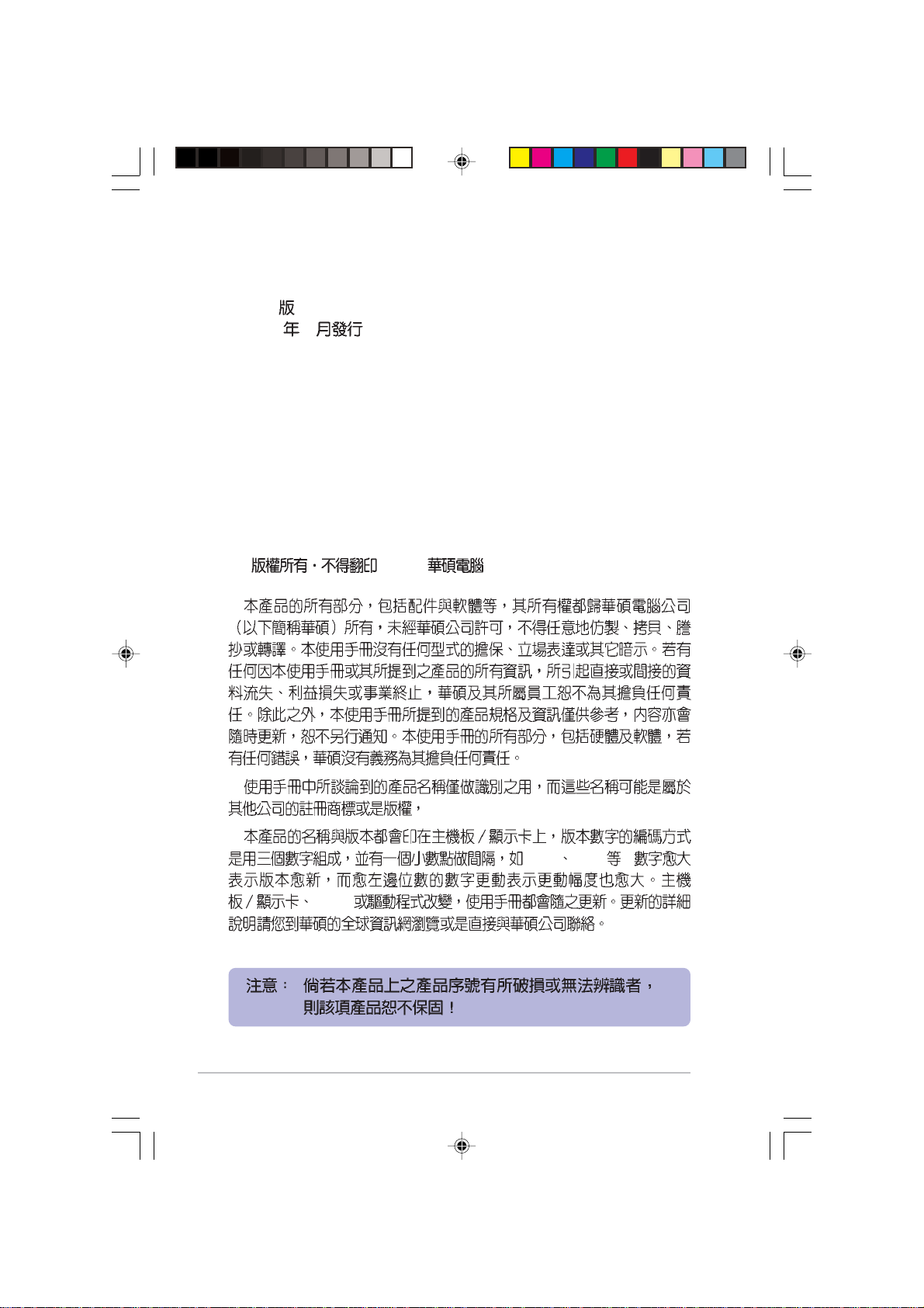
AS-D670
Page 2
T1914
3.00
2005 1
BIOS
© 2005
1.22 1.24 ...
2
Page 3
..........................................................................................
..................................................................................................
..............................................................................................
......................................................................................................
................................................................................................
........................................................................
1.1
1.2
1.3
1.4
1.5
1.5.1
1.5.2
1.5.3
1.6 CPU
1.6.1
1.6.2
.................................................................................................
.................................................................................................
.........................................................................................
.............................................................................................
......................................................................................
6
7
8
9
10
1-1
..................................................................
................................................................................
......................................................................
............................................................................
..........................................................................
......................................................................
1-3
1-3
1-6
1-8
1-9
1-9
1-10
1-10
1-11
1-11
1-14
1.7
1.8
1.7.1
1.7.2
1.7.3
1.7.4
1.8.1
1.8.2
...........................................................................................
..............................................................................................
..................................................................................
..........................................................................
..........................................................................
...............................................................................................
..................................................................................
..................................................................................
1-16
1-16
1-17
1-19
1-19
1-20
1-20
1-20
3
Page 4
1.8.3 PCI
1.8.4 PCI Express x16
1.8.5 PCI Express x1
1.9
1.10
1.10.1
1.10.2
...........................................................................................
...................................................................
.......................................................
.........................................................
.....................................................................
........................................................................
................................................................................
BIOS
2.1 BIOS
2.1.1
2.1.2 AFUDOS BIOS
2.1.3 EZ Flash BIOS
2.1.4 CrashFree BIOS 2 BIOS
2.1.5
2.2 BIOS
2.3 Main Menu
2.3.1 System Time [XX:XX:XXXX]
2.3.2 System Date [Day XX/XX/XXXX]
2.3.3 Legacy Diskette A [1.44M, 3.5 in.]
2.3.4 IDE Primary, Third and Fourth IDE Master/Slave.2-16
.....................................................................................
...................................................................
............................................................................
....................................................
.............................................
...............................
................................................................................
.........................................................................
.....................................................
..............................................
...............................................
1-22
1-22
1-22
1-23
1-26
1-26
1-28
2-3
2-3
2-4
2-6
2-7
2-9
2-12
2-15
2-15
2-15
2-15
2.3.5 IDE IDE Configuration
2.3.6 System Information
2.4 Advanced menu
2.4.1 USB USB Configuration
2.4.2 CPU Configuration
4
.........................................
...............................................
..............................................................
.......................................
............................................
2-17
2-18
2-19
2-19
2-20
Page 5
2.4.3 Chipset
2.4.4 OnBoard Devices Configuration
2.4.5 PCI PCI PnP
2.5 Power menu
2.5.1 Suspend Mode [Auto]
2.5.2 Repost Vedio on S3 Resume [No]
2.5.3 ACPI 2.0 Support [No]
2.5.4 ACPI APIC Support [Enabled]
2.5.5 APM Configuration
2.5.6 Hardware Monitor
2.6 Boot menu
2.6.1 Boot Device Priority
2.6.2 Boot Settings Configuration
2.6.3 Security
2.7 BIOS Exit menu
..................................................................
..................................................
....................................................................
...................................................................
.................................................
.................................................................
.....................................................
.........................................
......................................................................
......................................
.............................................................
............................................................
....................
...............................
..........................
2-21
2-23
2-24
2-26
2-26
2-26
2-26
2-26
2-27
2-28
2-30
2-30
2-31
2-32
2-34
3.1
3.2
3.2.1
3.2.2 Drivers menu
3.2.3 Utilities menu
3.2.4
3.2.5
3.3 Recovery CD
.........................................................................................
............................................................................
........................................................................................
3-3
..............................................................
....................................................
...................................................
..................................................
............................................................
3-3
3-3
3-4
3-5
3-6
3-7
3-9
5
Page 6
•
•
•
BIOS
BIOS
BIOS
6
Page 7
Pin
Jumper Mode
JumperFree™ Mode
[1-2]
[2-3]
1.
2.
12
Jumper Mode
23
Jumper Free
(Default)
http://tw.asus.com
•
•
•
•
•
•
•
•
•
•
7
Page 8
ASUSTeK COMPUTER INC.
15
886-2-2894-3447
0800-093-456
886-2-2890-7698
http://tw.asus.com/
ASUS COMPUTER INTERNATIONAL
44370 Nobel Drive, Fremont, CA 94538, USA
+1-502-995-0883
+1-502-933-8713
tmdl@asus.com
+1-502-995-0883
+1-502-933-8713
tsd@asus.com
http://www.asus.com
ASUS COMPUTER GmbH
Harkortstr. 25, 40880 Ratingen, BRD, Germany
49-2102-9599-31
sales@asuscom.de
49-2102-95990 ... /
49-2102-959910 ..
49-2102-959911
http://www.asuscom.de/support
http://www.asuscom.de
8
Page 9
•
•
•
•
•
•
•
•
•
•
•
•
/
9
Page 10
•
•
•
•
•
•
•
•
10
•
•
•
•
•
IC
Page 11
Page 12
1.1
1.2
1.3
1.4
1.5
1.5.1
1.5.2
1.5.3
1.6 CPU
1.6.1
1.6.2
1.7
1.7.1
1.7.2
1.7.3
1.7.4
1.8
1.8.1
1.8.2
1.8.3 PCI
1.8.4 PCI Express x16
1.8.5 PCI Express x1
1.9
1.10
1.10.1
1.10.2
.................................................................................................
.................................................................................................
.........................................................................................
.............................................................................................
........................................................................................
...........................................................................................
................................................................................................
....................................................................................
...............................................................................................
....................................................................................
....................................................................................
...........................................................................................
..................................................................
...................................................................................
.........................................................................
............................................................................
.............................................................................
.........................................................................
.............................................................................
.............................................................................
......................................................................
.........................................................
...........................................................
.....................................................................
...........................................................................
...................................................................................
1-3
1-3
1-6
1-8
1-9
1-9
1-10
1-10
1-11
1-11
1-14
1-16
1-16
1-17
1-19
1-19
1-20
1-20
1-20
1-22
1-22
1-22
1-23
1-26
1-26
1-28
Page 13
1.1
AS-D670
P5GD1-VM 800MHz
LGA 775 Pentium® 4 Intel® HyperThreading Technology 3.4GHz
915G
DDR400/333 DDR SDRAM Double
Data Rate SDRAM SDRAM
4GB
1.2
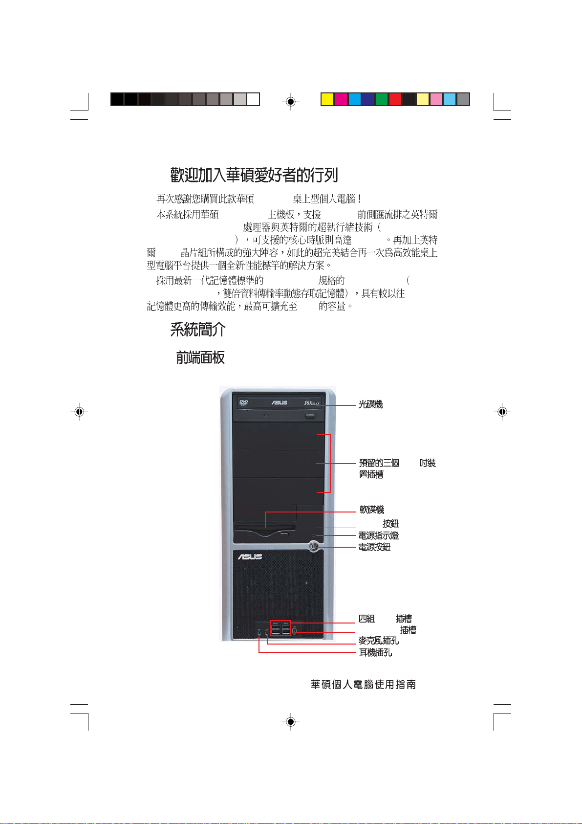
1.2.1
Reset
USB
IEEE-1394
5.25
1-3
Page 14
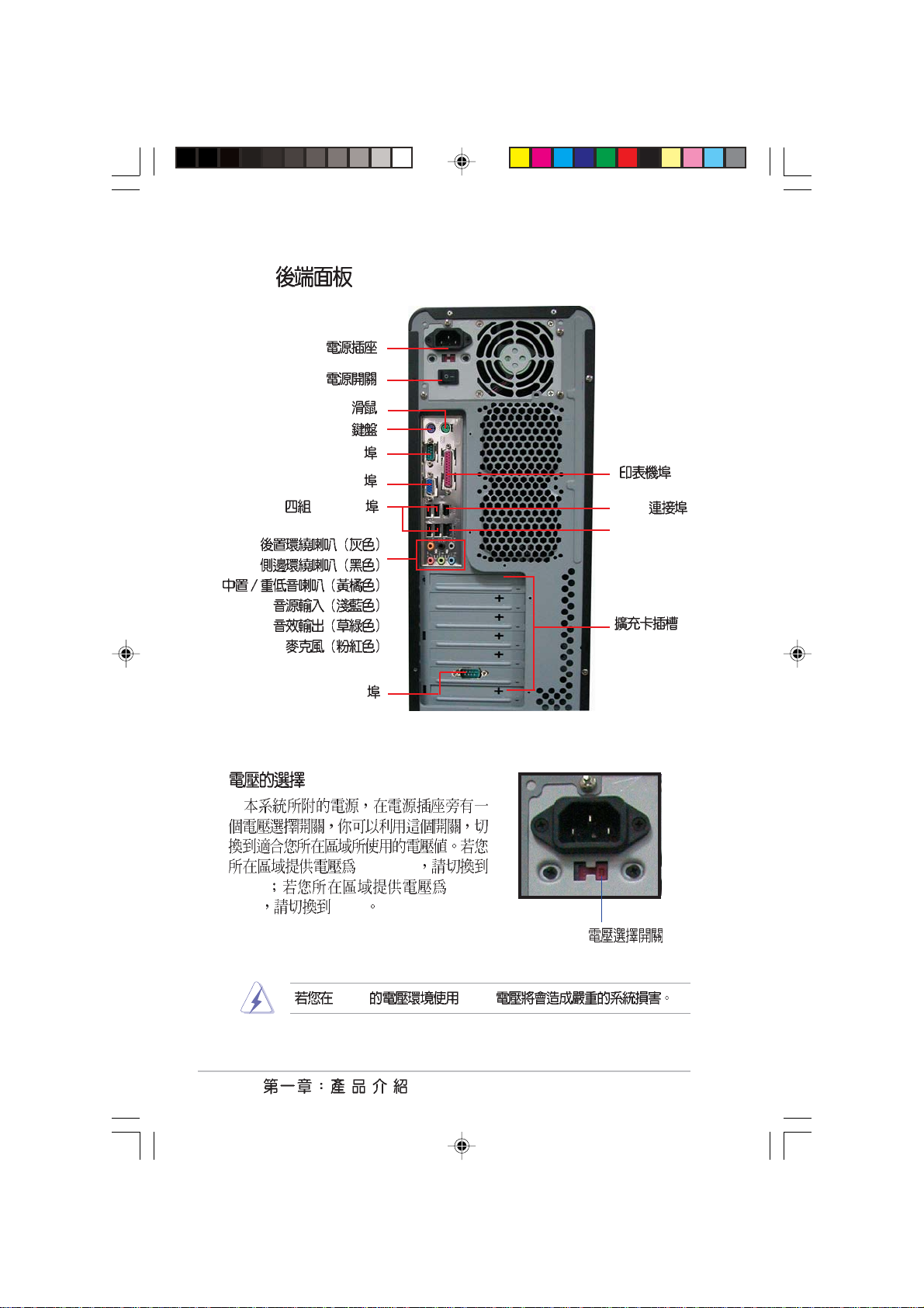
1.2.2
PS/2
PS/2
COM1
VGA
USB 2.0
COM2
1394
RJ-45 LAN
100-127V
115V 200240V 230V
230V 115V
1-4
115V/ 230V
Page 15
1.2.3
1.2.4
PS/2 USB PS/2
PS/2 USB
USB
PS/2
VGA
USB
PS/2
1394
RJ-45
1-5
Page 16
1.3
1.3.1
LGA 775 775 1MB L2
Pentium® 4 LGA 775 Pentium® 4 800
MHz FSB Hyper-Threading Technology
3.4GHz Intel® 04B 04A
Intel¤ 915G
Intel® 915G GMCH ICH6 I/
O
2D 3D
GMCH 533/800 MHz
FSB 775 400 MHz
DDR DVI-ADD2
PCI-Express x16
Intel® ICH6 I/O PCI Express
Dual Channel DDR
DDR400/333 DDR SDRAM Double Data
Rate SDRAM SDRAM
4GB 400MHz DDR SDRAM
3D
PCI ExpressTM
PCI ExpressTM I/O PCI
PCI Express
PCI
Serial ATA
Serial ATA SATA
Parallel ATA Serial ATA
150MB Parallel ATA
1-6
Page 17
24-bit DAC 16-bit DAC ALC861
S/PDIF
S/PDIF
S/PDIF
USB 2.0
USB 2.0 USB 1.1
12 Mbps USB 2.0 480 Mbps USB 2.0
USB 1.1
1.3.2
CrashFree BIOS 2
CrashFree BIOS 2 BIOS
BIOS
BIOS
BIOS ROM
Q-Fan
CPU
PC
CPU
EZ Flash BIOS
EZ Flash BIOS
BIOS MS-DOS
MyLogoTM
MyLogoTM
1-7
Page 18
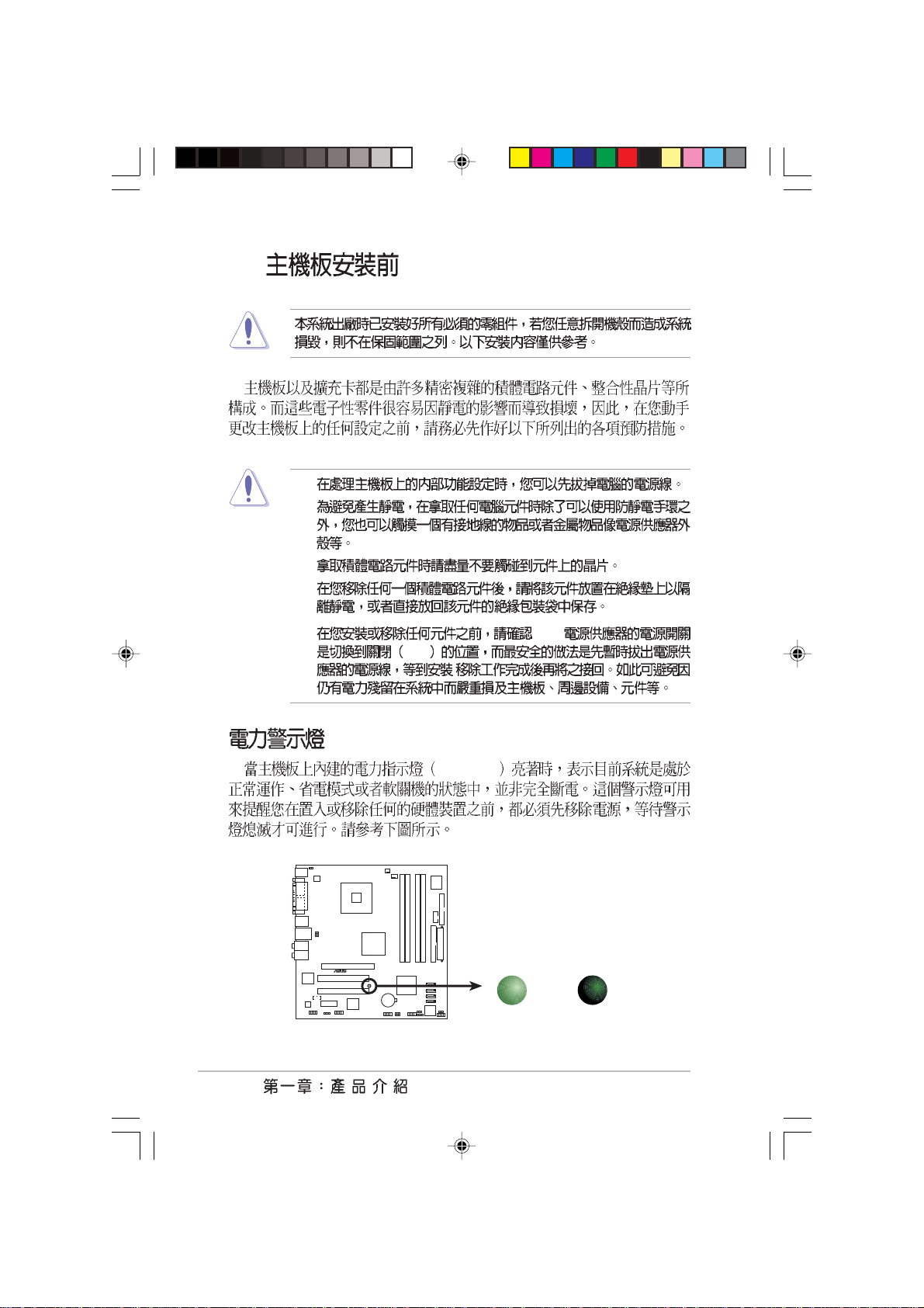
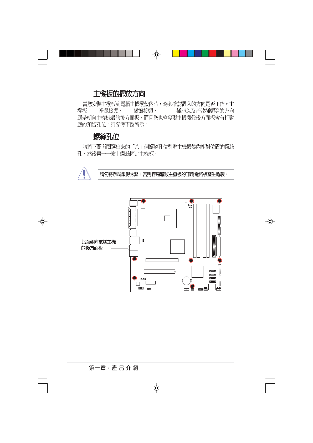
1.4
1.
2.
3.
4.
5. ATX
OFF
/
1-8
®
P5GD1-VM
P5GD1-VM Onboard LED
SB_PWR1
ON
Standby
Power
SB_PWR1
OFF
Powered
Off
Page 19
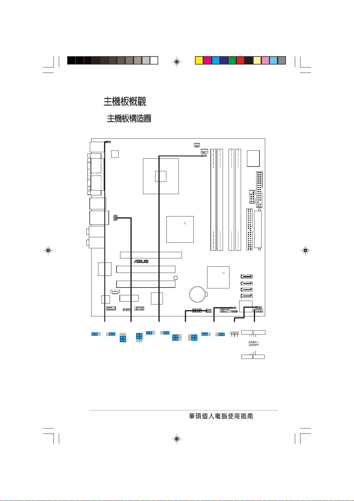
1.5
l
1.5.1
PS/2KBMS
T: Mouse
B: Keyboard
COM1
VGA1
Top:1394
F_USB12
LAN_USB34
Top:RearSpeaker Out
Center:
Side Speaker Out
Below:
Center/Subwoofer
Top:LineIn
Center:Line Out
Below:Mic In
Kinnereth
82541PI
PARALLELPORT
ALC880
CD1
KBPWR1
AAFP1
ATX12V1
USBPW34
USBPW12
PCIEX1_1
SPDIF_OUT1
LGA775
PCIEX16
®
PCI1
PCI2
TSB43AB22A
IE1394_2
CHA_FAN1
CPU_FAN1
FANPWR1
R
Intel
MCH
915G
DDR DIMM_A1 (64 bit,240-pin module)
DDR DIMM_A2 (64 bit,240-pin module)
DDR DIMM_B1 (64 bit,240-pin module)
P5GD1-VM
R
USBPW56
USBPW78
Intel
ICH6
SB_PWR1
CR2032 3V
Lithium Cell
TI
CMOS Power
USB56
SATA4
SATA3
SATA2
SATA1
CLRTC1
CHASSIS1USB78
DDR DIMM_B2 (64 bit,240-pin module)
PRI_IDE1
Intel FWH
4Mb
Super
COM2
F_PANEL1
I/O
FLOPPY1
EATXPWR1
PLED1
KBPWR1
+5V +5VSB
(Default)
USBPW12
USBPW34
2312
2
1
+5V
3
2
+5VSB
(Default)
FANPWR1
12
(Default)
USBPW56
USBPW78
23
21
DC modePWM
+5V
(Default)
2
+5VSB
3
CLRTC1
12 23
Normal Clear CMOS
(Default)
PLED1
1
NC
PLED-
PLED+
IDELED
*
Requires an ATX power supp
F_PANEL1
PWRSWIDE LED
PWR
GNDReset
PLED+
PLED-
Ground
IDE_LED-
IDE_LED+
RESET
1-9
Page 20
1.5.2
PS/2 PS/2 COM1/2
1.5.3
1-10
P5GD1-VM
Page 21
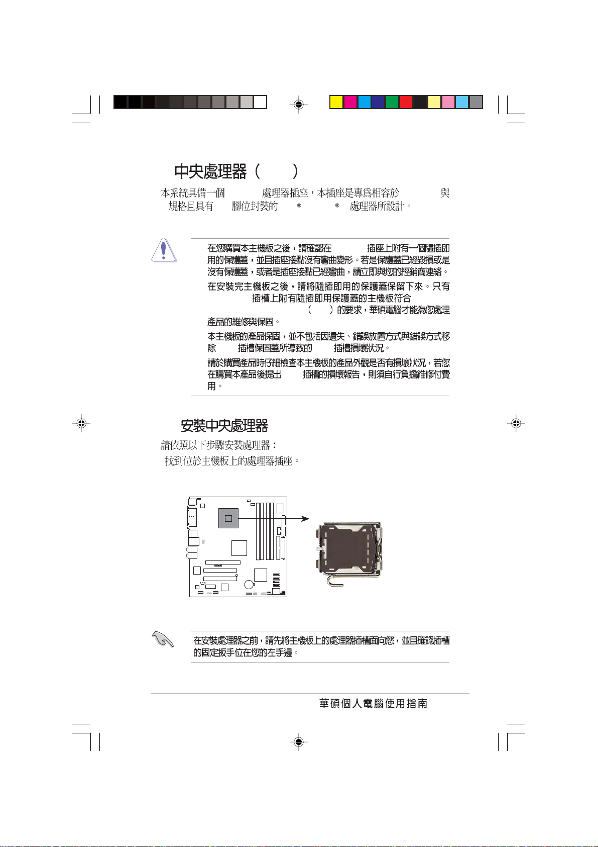
1.6 CPU
LGA775 PCG 04A
04B 775 Intel Pentium 4
1.6.1
1.
•
LGA775
•
LGA775 Return
Merchandise Authorization
RMA
•
CPU CPU
•
CPU
®
P5GD1-VM Socket 775
P5GD1-VM
1-11
Page 22
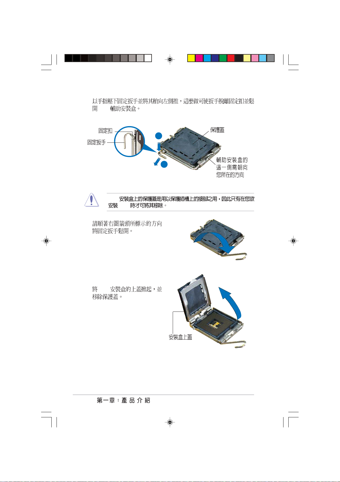
2.
CPU
A
B
CPU
CPU
3.
4. CPU
1-12
Page 23
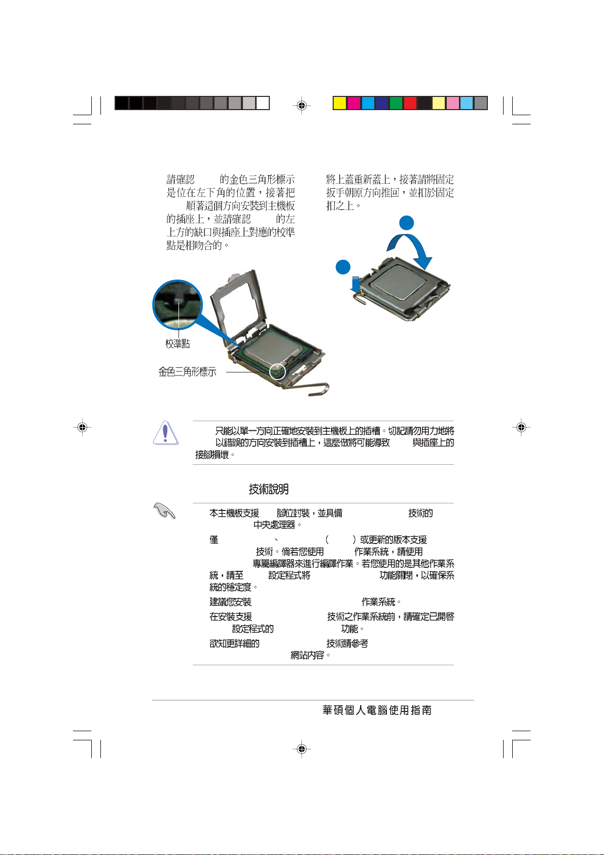
5. CPU
CPU
CPU
CPU CPU
CPU
6.
A
B
Intel Hyper-Threading
1. 775 Hyper-Threading Intel
Pentium® 4
2. Windows® XP Linux 2.4.x kernel HyperThreading
Threading
BIOS Hyper-Threading
3. Windows XP Service Pack 1
4. Hyper-Threading
BIOS Hyper-Threading
5. Hyper-Threading http://www.intel.com/
info/hyperthreading
®
Linux Hyper-
1-13
Page 24
Hyper-Threading
1. Hyper-Threading Intel® Pentium® 4
2. BIOS
Hyper-Threading Technology Enabled
Hyper-Threading CPU
3. BIOS
1.6.2
Intel® Pentium® 4 LGA775
•
1-14
•
•
Intel® 4-pin
•
Intel® Pentium® 4 LGA775
•
Intel® Pentium® 4 LGA775
Intel® Pentium® 4 LGA775
CPU
Page 25
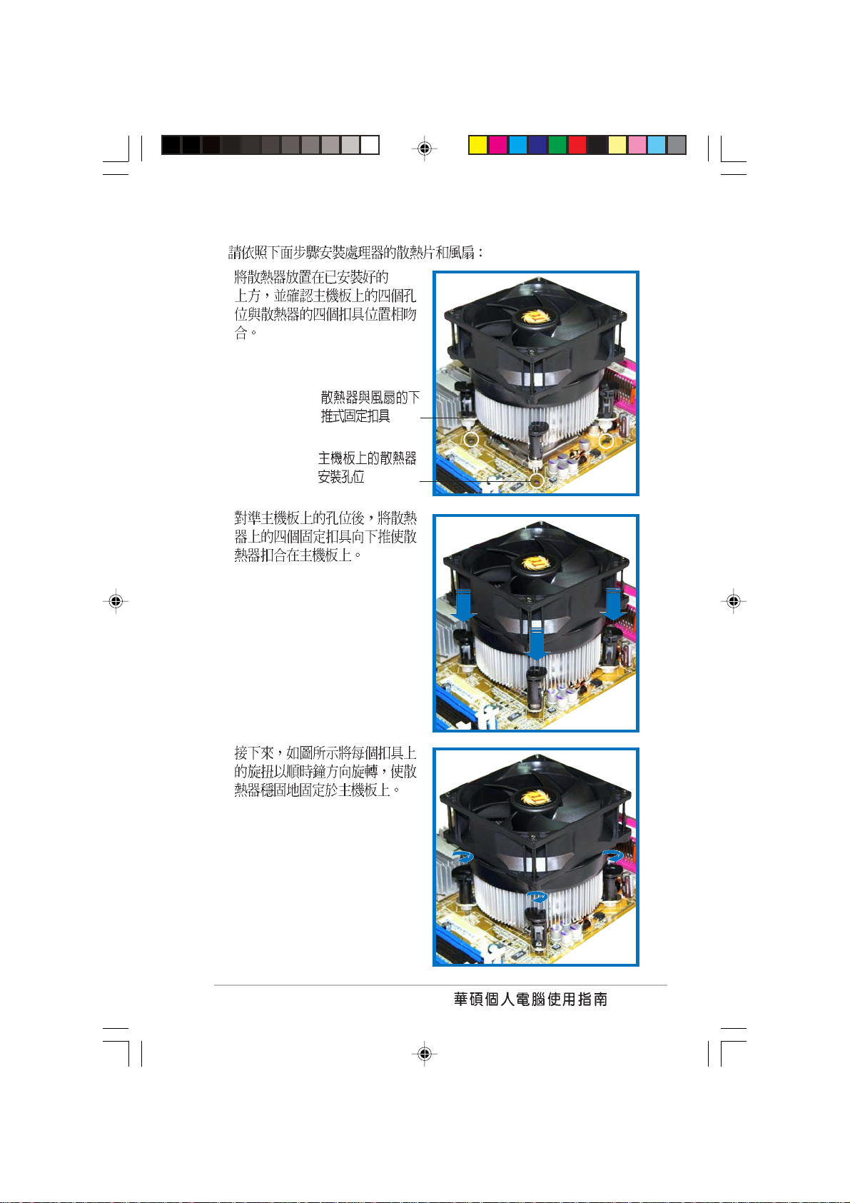
1. CPU
2.
3.
1-15
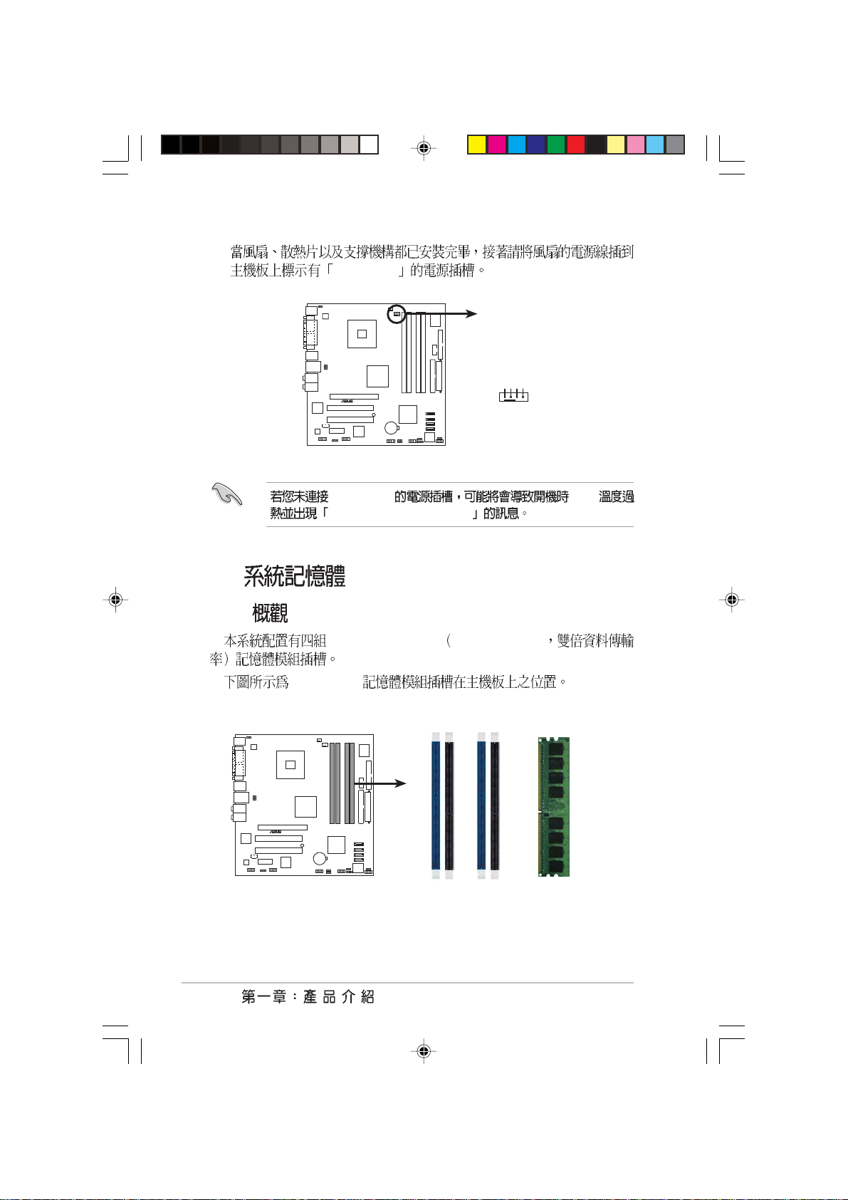
Page 26
4.
1.7
1.7.1
CPU_FAN1
CPU_FAN1
GND
CPU FAN PWR
CPU FAN IN
®
P5GD1-VM
CPU FAN PWM
P5GD1-VM CPU fan connector
CPU_FAN1 CPU
Hardware monitoring errors
184-pin DDR DIMM Double Data Rate
1-16
DDR DIMM
DIMM_A1
®
P5GD1-VM
P5GD1-VM 184-Pin DDR DIMM Sockets
DIMM_B1
DIMM_A2
DIMM_B2
Page 27
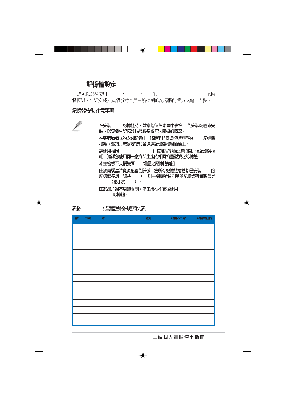
1.7.2
1 DDR400
256MB 512MB 1GB unbuffered non-ECC DDR
1. DDR 1
2. DDR
3. CL CAS-Latency
4. x16
5. 1GB
4GB
3+GB 4GB
6. 64Mb 128Mb DDR
DIMMs
CL SS/DS
256MB KINGSTON KVR400X64C3A/256 N/A Hynix SS HY5DU56822BT-D43 V V V
512MB KINGSTON KVR400X64C3A/512 N/A Hynix DS HY5DU56822BT-D43 V V V
256MB KINGSTON KVR400X64C3A/256 N/A Infineon SS HYB25D256800BT-5B V V V
512MB KINGSTON KVR400X64C3A/512 N/A Infineon DS HYB25D256809BT-5B V V V
256MB KINGSTON KVR400X64C3A/256 N/A KINGSTON SS D3208DL2T-5 V V V
512MB KINGSTON KVR400X64C3A/512 N/A KINGSTON DS D328DIB-50 V V V
512MB KINGSTON KHX3200A/512 N/A N/A DS Heat-Sink Package V V
256MB SAMSUNG M368L3223ETM-CCC N/A SAMSUNG SS K4H560838E-TCCC V V V
512MB SAMSUNG M368L6423ETM-CCC 3 SAMSUNG DS K4H560838E-TCCC V V
256MB SAMSUNG M368L3223FTN-CCC 3 SAMSUNG SS K4H560838F-TCCC V V
512MB SAMSUNG M368L6423FTN-CCC N/A SAMSUNG DS K4H560838F-TCCC V V
256MB Hynix HYMD232646B8J-D43 AA 3 Hynix SS HY5DU56822BT-D43 V V V
512MB Hynix HYMD264646B8J-D43 AA N/A Hynix DS HY5DU56822BT-D43 V V V
256MB MICRON MT8VDDT3264AG-40BCB N/A MICRON SS MT46V32M8TG-5BC V V V
512MB MICRON MT16VDDT6464AG-40BCB N/A MICRON DS MT46V32M8TG-5BC V V V
256MB Infineon HYS64D32300GU-5-B 3 Infineon SS HYB25D256800BT-5B V V V
512MB Infineon HYS64D64320GU-5-B 3 Infineon DS HYB25D256800BT-5B V V
256MB Infineon HYS64D32300HU-5-C 3 Infineon SS HYB25D256800CE-5C V V V
512MB Infineon HYS64D64320HU-5-C N/A Infineon DS HYB25D256800CE-5C V V V
256MB CORSAIR CMX256A-3200C2PT 2 Winbond SS W942508BH-5 V V V
512MB CORSAIR CMX512-3200C2 2 Winbond DS Heat-Sink Package V V V
512MB CORSAIR VS512MB400 2.5 VALUE seLecT DS VS32M8-5 V V V
256MB GEIL GE2563200B 2-6-3-3 GEIL SS GL3LC32G88TG-5A V V
512MB GEIL GE5123200B 2-6-3-3 GEIL DS GL3LC32G88TG-5A V V
256MB GEIL GD3200-256V 2.5-8-4-4 GEIL SS GLIL DDR 32M8 V V V
512MB GEIL GD3200-512V 2.5-8-4-4 GEIL DS GLIL DDR 32M8 V V V
256MB TwinMOS M2S9I08AFAPS9F0811A-T 2.5 PSC SS A2S56D30ATP V V
256MB TwinMOS M2G9I08AIATT9F081AADT 2.5 TwinMOS SS TMD7608F8E50D V V V
A* B* C*
(
1-17
Page 28
1 DDR400
256MB Transcend TS32MLD64V4F3 3 SAMSUNG SS K4H560838F-TCCC V V V
512MB Transcend TS64MLD64V4F3 3 SAMSUNG DS K4H560838F-TCCC V V V
1024MB Transcend TS128MLD64V4J 3 SAMSUNG DS K4H510838B-TCCC V V V
256MB Transcend TS32MLD64V4F3 3 Mosel SS V58C2256804SAT5B V V
512MB Transcend TS64MLD64V4F3 3 Mosel DS V58C2256804SAT5B V V
256MB Transcend TS32MLD64V4F3 3 SAMSUNG SS K4H560838E-TCCC V V
512MB Transcend TS64MLD64V4F3 3 SAMSUNG DS K4H560838E-TCCC V V V
256MB Apacer 77.10636.19G 3 Infineon SS HYB25D256807BT-5B V V V
512MB Apacer 77.10736.19G 3 Infineon DS HYB25D256807BT-5B V V V
256MB Apacer 77.10636.56G 3 Mosel SS V58C2256804SAT5 V V
512MB Apacer 77.10736.56G 3 Mosel DS V58C2256804SAT5B V V
256MB A DATA MDOSS6F3G31Y0K1E0Z 3 SAMSUNG SS K4H560838E-TCCC V V V
512MB A DATA MDOSS6F3H41Y0N1E0Z 3 SAMSUNG DS K4H560838F-TCCC V V V
256MB A DATA MDOHY6F3G31Y0N1E0Z 3 Hynix SS HY5DU56822CT-D43 V V V
512MB A DATA MDOHY6F3H41Y0N1E0Z 3 Hynix DS HY5DU56822CT-D43 V V V
256MB A DATA MDOAD5F3G31Y0D1E02 2.5 N/A SS ADD8608A8A-5B V V V
512MB A DATA MDOAD5F3H41Y0D1E02 2.5 N/A DS ADD8608A8A-5B V V
256MB Winbond W9425GCDB-5 3 Winbond SS W942508CH-5 V V V
512MB Winbond W9451GCDB-5 N/A Winbond DS W942508CH-5 V V V
512MB PSC AL6D8A53T1-5B N/A PSC DS A2S56D30ATP V V V
256MB PSC AL5D8B53T-5B1K 2.5 PSC SS A2S56D30BTP V V V
512MB PSC AL6D8B53T-5B1K 2.5 PSC DS A2S56D30BTP V V V
256MB KINGMAX MPXB62D-38KT3R N/A N/A SS KDL388P4LA-50 V V V
512MB KINGMAX MPXC22D-38KT3R N/A N/A DS KDL388P4LA-50 V V V
512MB ATP AG64L64T8SQC4S N/A SAMSUNG DS K4H560838D-TCC4 V V V
1024MB ATP AG28L64T8SMC4M N/A MICRON DS MT46V64M4TG-5BC V V
256MB NANYA NT256D64S88B1G-5T 3 NANYA SS NT5DS32M8BT-5T V V
512MB NANYA N512D64S8HB1G-5T 3 NANYA DS NT5DS32M8BT-5T V V V
256MB NANYA NT256D64S88C0G-5T 3 N/A SS NT5DS32M8CT-5T V V
512MB NANYA NT512D64S8HC0G-5T 3 N/A DS NT5DS32M8CT-5T V V V
256MB BRAIN POWER B6U808-256M-SAM-400 N/A SAMSUNG SS K4H560838D-TCC4 V V V
512MB BRAIN POWER B6U808-512M-SAM-400 N/A SAMSUNG DS K4H560838D-TCC4 V V V
256MB CENTURY DXV6S8SSCCD3K27C N/A SAMSUNG SS K4H560838D-TCCC V V V
512MB CENTURY DXV2S8SSCCD3K27C N/A SAMSUNG DS K4H560838D-TCCC V V V
256MB CENTURY DXV6S8SSCCE3K27E N/A SAMSUNG SS K4H560838E-TCCC V V V
512MB CENTURY DXV2S8SSCCE3K27E N/A SAMSUNG DS K4H560838E-TCCC V V V
256MB CENTURY DXV6S8MC5BC3U27E N/A MICRON SS MT46V32M8TG-5BC V V V
512MB CENTURY DXV2S8MC5BC3U27E N/A MICRON DS MT46V32M8TG-5BC V V V
256MB elixir M2U25664DS88B3G-5T N/A NANYA SS N2DS25680BT-5T V V V
512MB elixir M2U25664DS8HB3G-5T 3 NANYA DS N2DS25680BT-5T V V
256MB Kreton N/A N/A VT SS VT3225804T-5 V V V
512MB Kreton N/A N/A VT DS VT3225804T-5 V V V
256MB Veritech VT400FMV/2561103 3 VT SS VT56DD32M8PC-5 V V V
256MB Pmi MD44256VIT3208GMHA01 2.5 MOSEL SS V58C2256804SAT5B V V V
512MB Pmi MD44512VIT3208GATA03 2.5 MOSEL DS V58C2256804SAT5B V V V
256MB MOSEL V826632K24SCTG-D0 2.5 N/A SS V58C2256804SCT5B V V V
512MB MOSEL V826664K24SCTG-D0 2.5 N/A DS V58C2256804SCT5B V V V
1-18
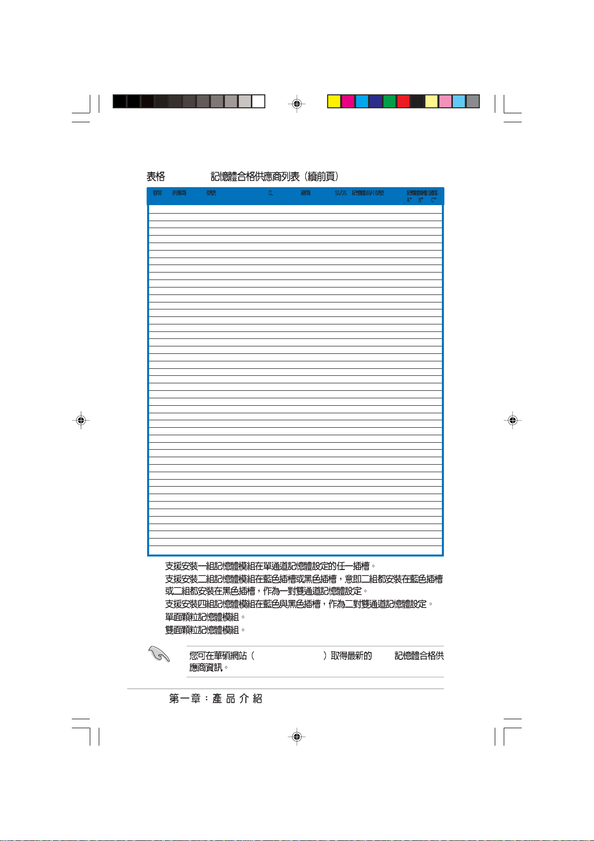
A B -
C SS DS -
http://tw.asus.com DDR
Page 29

1.7.3
1.
2.
3.
DDR DIMM
1.7.4
1.
2.
1-19
Page 30

1.8
1.8.1
1.
2.
3.
4.
5.
6.
/
1.8.2
1. BIOS
BIOS
2. IRQ
3.
1-20
Page 31

IRQ
01
12
2 N/A IRQ#9
311 COM 2 *
412 COM 1 *
513 PCI *
614
715 LPT 1 *
83 CMOS/
94 PCI *
10 5 PCI *
11 6 PCI *
12 7 PS/2 *
13 8
14 9 IDE
15 10 IDE
*
AB CDEFGH
1 PCI - ---- --
2 PCI - ----- PCI E x16 ------PCI E x1 - ------
USB 1- ----- USB 2- - - --- USB 3- - --- - USB 4 ------ USB 2.0 - ----- Azalia ------ IDE -- -- - - SATA --- ----
- --- ---
PCI IDE - --- ---
IRQ
PCI
IRQ IRQ
1-21
Page 32
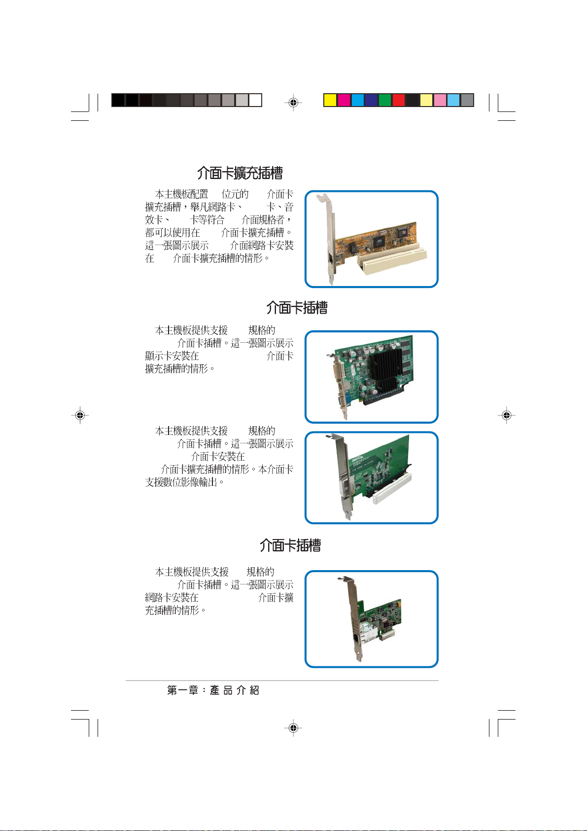
1.8.3 PCI
32 PCI
SCSI
USB PCI
PCI
PCI
PCI
1.8.4 PCI Express x16
x16 PCI
Express
PCI Express x16
x16 PCI
Express
DVI ADD2 PCI Express
x16
1.8.5 PCI Express x1
x1 PCI
Express
PCI Express x1
1-22
Page 33

1.9
1. CMOS CLRTC1
CMOS
CMOS
1.
2.
3. CLRTC1 [1-2] [2-3]
CMOS [1-2]
4.
5.
6. Del BIOS
BIOS
CMOS CLRTC
®
P5GD1-VM Clear RTC RAM
P5GD1-VM
BIOS
CLRTC1
12 23
Normal Clear CMOS
(Default)
C.P.R CPU
1-23
Page 34

2. USB 3-pin USBPW12, USBPW34, USBPW56,
USBPW78
+5V USB S1
+5VSB S3 S4
KBPWR1
2312
®
P5GD1-VM
P5GD1-VM Keyboard power setting
1. USB +5VSB
500mA/+5VSB
2.
+5VSB
3. 3-1 pin PLED1
+5V +5VSB
(Default)
1-24
®
P5GD1-VM
P5GD1-VM PLED setting
PLED1
1
NC
PLED+
PLED-
Page 35

4. 3-pin KBPWR1
+5VSB [1-2]
+5V
1A/+5VSB BIOS
KBPWR1
2312
[2-3]
®
P5GD1-VM
P5GD1-VM Keyboard power setting
5. 3-pin FANPWR1
4-pin CPU [1-2]
3-pin CPU [2-3]
®
P5GD1-VM FAN power setting
P5GD1-VM
+5V +5VSB
(Default)
FANPWR1
12
(Default)
23
DC modePWM
4-pin CPU
1-25
Page 36

1.10
1.10.1
1
15
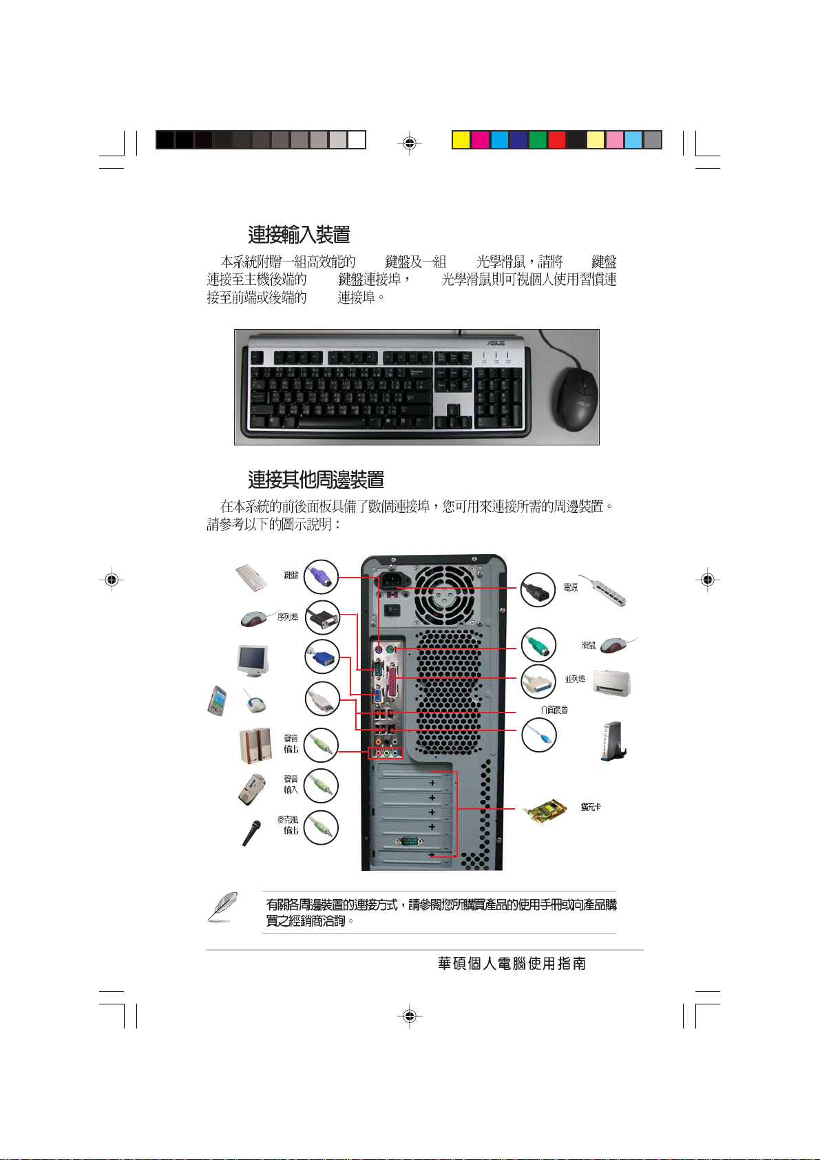
1. PS/2 PS/2
2. 25-pin
3. 1394 1394
4. RJ-45
5.
6.
7.
14
LAN Local Area Network
2 4
13
3
12
56
11
7
8
9
10
1-26
8.
9.
10.
/
Page 37

11. USB 2.0 3 4 USB
USB 2.0
12. USB 2.0 1 2 USB
USB 2.0
13. VGA 15-pin VGA
VGA
14. 9-pin COM1
15. PS/2 PS/2
1-27
Page 38

1.10.2
1. 34-1 pin FLOPPY1
pin 5 pin 5
FLOPPY1
NOTE: Orient the red markings on
the floppy ribbon cable to PIN 1.
®
P5GD1-VM
PIN 1
P5GD1-VM Floppy disk drive connector
Pin 1
1-28
Page 39

2. IDE 40-1 pin PRI_IDE1
Slave UltraDMA100/66 IDE
UltraDMA100/66 IDE
Slave UltraDMA100/66
UltraDMA100/66
Primary
Master
•
•
IDE UltraATA
80 IDE UltraDMA 100/66 IDE
®
P5GD1-VM
P5GD1-VM IDE connector
PRI_IDE1
NOTE: Orient the red markings
(usually zigzag) on the IDE
ribbon cable to PIN 1.
Pin 1
PIN 1
1-29
Page 40

3. Serial ATA 7-pin SATA1, SATA2, SATA3, SATA4
Serial ATA
Serial ATA
®
P5GD1-VM
P5GD1-VM SATA connectors
Serial ATA
Serial ATA Windows XP Service Pack 1
•
Windows 2000 Service Pack 4
standard IDE mode Primary
•
Serial ATA Master Slave
SATA4
SATA3
SATA2
SATA1
SATA1 SATA2
RSATA_TXP4
RSATA_TXN4
RSATA_RXP4
RSATA_RXN4
RSATA_TXP3
RSATA_TXN3
RSATA_RXP3
RSATA_RXN3
RSATA_TXP2
RSATA_TXN2
RSATA_RXP2
RSATA_RXN2
RSATA_TXP1
RSATA_TXN1
RSATA_RXP1
RSATA_RXN1
GND
GND
GND
GND
GND
GND
GND
GND
GND
GND
GND
GND
1-30
SATA1, SATA2 Master
SATA3, SATA4 Slave
Page 41

4. / 4-pin CPU_FAN1,3-pin CHA_FAN1
350 740 8.88 1 2.2 26.
64 /+12
+12V GND
CPU_FAN1CHA_FAN1
GND
Rotation
+12V
GND
CPU FAN PWR
CPU FAN IN
®
P5GD1-VM
CPU FAN PWM
P5GD1-VM Fan connectors
1-31
Page 42

5. USB 10-1 pin USB56, USB78
USB
USB USB
USB 2.0 480 Mbps USB 1.1 12 Mbps
40
®
P5GD1-VM
P5GD1-VM USB 2.0 connectors
1394 USB
USB
USB56
1
USB+5V
USB_P6-
USB_P6+
USB+5V
USB_P5-
USB_P5+
GND
GND
NC
USB78
1
USB+5V
USB_P8-
USB_P8+
USB+5V
USB_P7-
USB_P7+
GND
GND
NC
1-32
Page 43

6. 24-pin EATXPWR, 4-pin ATX12V
ATX +12V
24 EATXPWR1
+12V
GND
+12V DC
®
P5GD1-VM
P5GD1-VM ATX power connectors
•
2.0 24-pin ATX 12V
300W
•
24-pin ATX 12V +12V
15 350W 4-pin ATX +12V
•
ATX 12V 300W Spec. 2.0
•
Parallel ATA IDE hard disk drive (x 2)
Serial ATA SATA hard disk drive
ATX12V1
®
Intel
GND
+12V DC
Pentium
+5V Standby
EATXPWR1
+3 Volts
+12 Volts
+12 Volts
Power OK
Ground
+5 Volts
Ground
+5 Volts
Ground
+3 Volts
+3 Volts
®
4 3.4 GHz
512 MB DDR (x 4)
PCI Express x16 Nvidia EN5900
CD-ROM (x 2)
Ground
+5 Volts
+5 Volts
+5 Volts
-5 Volts
Ground
Ground
Ground
PSON#
Ground
-12 Volts
+3 Volts
•
1-33
Page 44

7. 4-pin CD1
CD1
®
P5GD1-VM
P5GD1-VM CD audio connector
8. 10-1 pin AAFP1
Intel
AZalia /
®
P5GD1-VM Analog front panel connector
P5GD1-VM
Ground
Ground
Left Audio Channel
Right Audio Channel
CD-in
/ HD Audio
AAFP1
Azalia
compliant definition
SENSE2_RETUR
SENSE1_RETUR
PRESENCE#
GND
PORT1 L
PORT2 L
PORT2 R
PORT1 R
SENSE_SEND
Legacy AC’97
compliant definition
+5VA
AGND
MIC2
MICPWR
BLINE_OUT_L
BLINE_OUT_R
NC
Line out_L
Line out_R
1-34
Page 45

9. 4-1 pin CHASSIS1
Signal GND
Chassis Signal GND
CHASIS1 Chassis
CHASSIS1
®
P5GD1-VM
P5GD1-VM Chassis intrusion connector
10. 4-1 pin SPDIF_OUT1
S/PDIF
PDIF
+5V
®
P5GD1-VM Digital audio connector
P5GD1-VM
SPDIF_OUT1
+5VSB_MB
Chassis Signal
GND
(Default)
S/PDIF S/
GND
SPDIFOUT
1-35
Page 46

11. 20-pin PANEL
®
P5GD1-VM System panel connector
P5GD1-VM
PWRSWPLED
GNDReset
PWR
PLED+
PLED-
F_PANEL1
Ground
IDE_LED-
IDE_LED+
IDELED
*
Requires an ATXpower supply.
RESET
•
IDE 2-pin IDELED
•
3-1pin PLED
IDE_LED IDE
IDE
ATX / 2-pin PWRSW
•
BIOS
•
2-pin RESET
Reset
1-36
Page 47

BIOS
BIOS
BIOS
BIOS
Page 48

2.1 BIOS
2.1.1
2.1.2 AFUDOS BIOS
2.1.3 EZ Flash BIOS
2.1.4 CrashFree BIOS 2 BIOS
2.1.5
2.2 BIOS
2.3 Main Menu
2.3.1 System Time [XX:XX:XXXX]
2.3.2 System Date [Day XX/XX/XXXX]
2.3.3 Legacy Diskette A [1.44M, 3.5 in.]
2.3.4 IDE Primary, Third and Fourth IDE Master/Slave
2.3.5 IDE IDE Configuration
2.3.6 System Information
2.4 Advanced menu
2.4.1 USB USB Configuration
2.4.2 CPU Configuration
2.4.3 Chipset
2.4.4 OnBoard Devices Configuration
2.4.5 PCI PCI PnP
2.5 Power menu
2.5.1 Suspend Mode [Auto]
2.5.2 Repost Vedio on S3 Resume [No]
2.5.3 ACPI 2.0 Support [No]
2.5.4 ACPI APIC Support [Enabled]
2.5.5 APM Configuration
2.5.6 Hardware Monitor
2.6 Boot menu
2.6.1 Boot Device Priority
2.6.2 Boot Settings Configuration
2.6.3 Security
2.7 BIOS Exit menu
...................................................................................
.....................................................................................
...................................................................
...............................................................................
......................................................
................................................
.................................
.........................................................................
.......................................................
.................................................
..................................................
............................................
..................................................
..............................................................
..........................................
..............................................
.....................................................................
......................
....................................................
....................................................................
......................................................................
...................................................
....................................................................
........................................................
..................................
............................................
......................................................................
........................................
.............................
................................................................
............................................................
...
2-3
2-3
2-4
2-6
2-7
2-9
2-12
2-15
2-15
2-15
2-15
2-16
2-17
2-18
2-19
2-19
2-20
2-21
2-23
2-24
2-26
2-26
2-26
2-26
2-26
2-27
2-28
2-30
2-30
2-31
2-32
2-34
Page 49

2.1 BIOS
BIOS Basic Input/Output
System
1. ASUS AFUDOS DOS BIOS
2. ASUS EZ Flash POST BIOS
3. ASUS CrashFree BIOS 2 BIOS
BIOS
4. ASUS Update Windows BIOS
BIOS
BIOS AFUDOS
BIOS
2.1.1
1.
DOS
a. 1.44MB
b. DOS format A:/S Enter
Windows XP
a. 1.44MB
b. Windows
c. 3 1/2
d. File Format Format 3 1/2
Floppy Disk
e. Create a MS-DOS startup disk
Windows 2000
a. 1.44MB
b. Windows 2000
c. Run
d. D:\bootdisk\makeboot a:
D
e. Enter
2. BIOS
2-3
Page 50

2.1.2 AFUDOS BIOS
AFUDOS DOS BIOS
BIOS AFUDOS BIOS
BIOS
BIOS
•
600KB
BIOS
•
BIOS
1. AFUDOS afudos.exe
2. DOS
afudos /o[filename]
filename
A:\>afudos /oOLDBIOS1.ROM
3. Enter BIOS
A:\>afudos /oOLDBIOS1.ROM
AMI Firmware Update Utility - Version 1.10
Copyright (C) 2002 American Megatrends, Inc. All rights reserved.
Reading flash ..... done
A:\>
2-4
BIOS DOS
BIOS
Page 51

BIOS
AFUDOS BIOS
1. tw.asus.com BIOS
BIOS
BIOS
2. AFUDOS.EXE BIOS
3. DOS
afudos /i[filename]
filename
BIOS
A:\>afudos /iP5GD1-VM.ROM
4. AFUDOS BIOS
A:\>afudos /iP5GD1-VM.ROM
AMI Firmware Update Utility - Version 1.10
Copyright (C) 2002 American Megatrends, Inc. All rights reserved.
Reading file ..... done
Erasing flash .... done
Writing flash .... 0x0008CC00 (9%)
BIOS
5. BIOS DOS
A:\>afudos /iP5GD1-VM.ROM
AMI Firmware Update Utility - Version 1.10
Copyright (C) 2002 American Megatrends, Inc. All rights reserved.
Reading file ..... done
Erasing flash .... done
Writing flash .... 0x0008CC00 (9%)
Verifying flash .. done
A:\>
2-5
Page 52

2.1.3 EZ Flash BIOS
EZ Flash BIOS
DOS EZ Flash BIOS
Power-On Self Test POST
Alt + F2 EZ Flash
EZ Flash BIOS
1. tw.asus.com BIOS
P5GD1-VM.ROM
2.
3. POST Alt + F2
EZ Flash
EZFlash starting BIOS update
Checking for floppy...
4. BIOS
EZ Flash BIOS
EZFlash starting BIOS update
Checking for floppy...
Floppy found!
Reading file “P5GD1-VM.ROM”. Completed.
Start erasing.......|
Start Programming...|
Flashed successfully. Rebooting.
2-6
•
•
not found
BIOS
BIOS
Floppy
BIOS
P5GD1-VM.ROM not found
BIOS P5GD1-VM.ROM
Page 53

2.1.4 CrashFree BIOS 2 BIOS
CrashFree BIOS 2 BIOS
BIOS BIOS
1. BIOS
BIOS
2. BIOS P5GD1-VM.ROM
BIOS
BIOS
1.
2. BIOS
3.
BIOS
Bad BIOS checksum. Starting BIOS recovery...
Checking for floppy...
BIOS
Bad BIOS checksum. Starting BIOS recovery...
Checking for floppy...
Floppy found!
Reading file “P5GD1-VM.ROM”. Completed.
Start flashing...
BIOS
4.
2-7
Page 54

BIOS
BIOS
1.
2.
3. BIOS
Bad BIOS checksum. Starting BIOS recovery...
Checking for floppy...
Bad BIOS checksum. Starting BIOS recovery...
Checking for floppy...
Floppy not found!
Checking for CD-ROM...
CD-ROM found.
Reading file “P5GD1-VM.ROM”. Completed.
Start flashing...
4. BIOS
2-8
BIOS
BIOS BIOS
http://tw.asus.com BIOS
BIOS
Page 55

2.1.5
BIOS
1. BIOS
2. BIOS
3. BIOS BIOS
4. BIOS
5. BIOS
1.
2.
3.
Windows
ISP
BIOS
2-9
Page 56

BIOS
BIOS
1. ASUS ASUSUpdate ASUSUpdate
2. Update BIOS
from the Internet
Next
3. FTP
Auto Select
Next
2-10
BIOS
Page 57

4. BIOS
Next
5.
BIOS
BIOS
BIOS BIOS
BIOS BIOS
1. ASUS
ASUSUpdate ASUSUpdate
2. Update BIOS
from a file Next
3. BIOS
4.
BIOS
2-11
Page 58

2.2 BIOS
BIOS Basic Input and Output System
BIOS
BIOS
BIOS
RUN SETUP
BIOS
BIOS
Flash ROM BIOS Flash ROM
BIOS BIOS
BIOS
CMOS RAM
BIOS
POST Power-On Self Test
Delete Delete
2-12
Reset Ctrl + Alt +
Delete
BIOS
1. BIOS
BIOS
2.7 BIOS Load Setup
Defaults
2. BIOS
3. http://tw.asus.com BIOS
BIOS
BIOS
Page 59

2.2.1 BIOS
System Time [11:51:19]
System Date [Thu 06/10/2004]
Legacy Diskette A [1.44M, 3.5 in]
Primary IDE Master : [ST320413A]
Primary IDE Slave : [Pioneer CD-ROM ATA]
Third IDE Master : [Not Detected]
Third IDE Slave : [Not Detected]
Fourth IDE Master : [Not Detected]
Fourth IDE Slave : [Not Detected]
IDE Configuration
System Information
2.2.2
BIOS
Main
Advanced
Power
Boot
Exit BIOS
Use [ENTER], [TAB] or
[SHIFT-TAB] to select
a field.
Use [+] or [-] to
configure the System
time.
2.2.3
2-13
Page 60

2.2.4
Main
Advanced Power Boot Exit
2.2.5
2.2.6
2.2.7
System Time [11:51:19]
System Date [Thu 06/10/2004]
Legacy Diskette A [1.44M, 3.5 in]
Primary IDE Master : [ST320413A]
Primary IDE Slave : [Pioneer CD-ROM ATA]
Third IDE Master : [Not Detected]
Third IDE Slave : [Not Detected]
Fourth IDE Master : [Not Detected]
Fourth IDE Slave : [Not Detected]
IDE Configuration
System Information
Enter
Advanced PCI/PnP Settings
WARNING: Setting wrong values in
below sections may cause system to
malfunction.
Plug And Play O/S [No]
PCI Latency Timer [64]
Allocate IRQ to PCI VGA [Yes]
Palette Snooping [Disabled]
PCI IDE BusMaster [Enabled]
Use [ENTER],
[TAB] or [SHIFTTAB] to select a
field.
Use [+] or [-] to
configure the
System time.
2-14
Enter
2.2.8
PageUp PageDown
2.2.9
BIOS
Page 61

2.3 Main Menu
BIOS
2.2.1 BIOS
System Time [11:51:19]
System Date [Thu 06/10/2004]
Legacy Diskette A [1.44M, 3.5 in]
Primary IDE Master : [ST320413A]
Primary IDE Slave : [Pioneer CD-ROM ATA]
Third IDE Master : [Not Detected]
Third IDE Slave : [Not Detected]
Fourth IDE Master : [Not Detected]
Fourth IDE Slave : [Not Detected]
IDE Configuration
System Information
Use [ENTER], [TAB] or
[SHIFT-TAB] to select
a field.
Use [+] or [-] to
configure the System
time.
2.3.1 System Time [XX:XX:XXXX]
00 23 00 59 00 59 Tab
Tab + Shift
2.3.2 System Date [Day XX/XX/XXXX]
1 12 1 31 2099 Tab Tab +
Shift
2.3.3 Legacy Diskette A [1.44M, 3.5 in.]
[Disabled] [360K, 5.25
in.] [1.2M, 5.25 in.] [720K, 3.5 in.] [1.44M, 3.5 in.] [2.88M, 3.5 in.]
2-15
Page 62

2.3.4 IDE Primary, Third and Fourth IDE
Master/Slave
BIOS IDE
IDE Enter
Primary IDE Master
Device : Hard Disk
Vendor : ST320413A
Size : 20.0GB
LBA Mode : Supported
Block Mode : 16 Sectors
PIO Mode : Supported
Async DMA : MultiWord DMA-2
Ultra DMA : Ultra DMA-5
SMART Monitoring : Supported
Type [Auto]
LBA/Large Mode [Auto]
Block(Multi-sector Transfer)[Auto]
PIO Mode [Auto]
Smart Monitoring [Auto]
32Bit Data Transfer [Disabled]
Select the type of
device connected to
the system.
Device Vendor Size LBA Mode Block
Mode PIO Mode Async DMA Ultra DMA SMART monitoring
BIOS N/A
Type [Auto]
IDE Auto
IDE CDROM IDE
ARMD ATAPI IDE
ZIP LS-120 MO [Not Installed]
[Auto] [CDROM] [ARMD]
LBA/Large Mode [Auto]
LBA [Auto]
LBA LBA
[Disabled] [Auto]
Block (Multi-sector Transfer) [Auto]
[Disabled]
[Disabled] [Auto]
2-16
BIOS
[Auto]
Page 63

PIO Mode [Auto]
PIO [Auto] [0] [1] [2] [3] [4]
DMA Mode [Auto]
DMA [Auto] [SWDMA0] [SWDMA1] [SWDMA2]
[MWDMA0] [MWDMA1] [MWDMA2] [UDMA0] [UDMA1] [UDMA2]
[UDMA3] [UDMA4] [UDMA5]
SMART Monitoring [Auto]
Smart Monitoring, Analysis, and
Reporting Technology [Auto] [Disabled] [Enabled]
32Bit Data Transfer [Disabled]
32 [Disabled] [Enabled]
2.3.5 IDE IDE Configuration
IDE
Enter
IDE Configuration
Onboard IDE Operate Mode [Enhanced Mode]
Enhanced Mode Support On [SATA mode]
IDE Detect Time Out (Sec) [35]
Set to [Compatible
Mode] when Legacy OS
(i.e. WIN ME, 98,
NT4.0, MS DOS is
used.
Set to [Enhanced Mode
when Native OS) i.e.
WIN 2000, WIN XP) is
used.
Onboard IDE Operate Mode [Enhanced Mode]
MS-DOS Windows 98SE/ME [Compatible Mode]
Windows 2000/XP [Enhanced Mode]
[Disabled] [Compatible Mode] [Enhanced Mode]
2-17
Page 64

Enhanced Mode Support On [S-ATA mode]
[S-ATA]
ATA ATA
MS-DOS Windows
98SE/ME ATA ATA
[P-ATA+S-ATA] [P-ATA]
[S-ATA]
[P-ATA+S-ATA] [S-ATA Mode] [P-ATA]
IDE Detect Time Out [35]
ATA/ATAPI [0] [5]
[10] [15] [20] [25] [30] [35]
2.3.6 System Information
BIOS
AMIBIOS
Version : 08.00.10
Build Date : 06/10/04
Processor
Type : Genuine Intel(R) CPU 3.20GHz
Speed : 3200 MHz
Count : 1
System Memory
Size : 248MB
AMI BIOS
Processor
System Memory
2-18
BIOS
BIOS
Page 65

2.4 Advanced menu
USB Configuration
CPU Configuration
Chipset
Onboard Devices Configuration
PCI PnP
Configure the USB
support.
2.4.1 USB USB Configuration
USB
USB Configuration
Module Version - 2.23.2-9.4
USB Devices Enabled: None
USB Function [Enabled]
Legacy USB Support [Auto]
USB 2.0 Controller [Enabled]
USB 2.0 Controller Mode [HiSpeed]
USB Function [Enabled]
USB [Disabled] [Enabled]
Enables USB host
controllers.
2-19
Page 66

Legacy USB Support [Auto]
USB [Auto]
USB USB
[Disabled]
USB USB
[Disabled] [Enabled] [Auto]
USB 2.0 Controller [Enabled]
USB 2.0 [Diabled] [Enabled]
USB 2.0 Controller MODE [HiSpeed]
USB 2.0 HiSpeed 480
Mbps Full Speed 12 Mbps [HiSpeed] [Full Speed]
2.4.2 CPU Configuration
Configure Advanced CPU settings
Manufacturer: Intel
Brand String: Genuine Intel(R) CPU 3.20GHz
Frequency : 3200 MHz
FSB Speed : 800 MHz
Cache L1 : 16 KB
Cache L2 : 1024 KB
Cache L3 : 0 KB
Ratio Status: Unlocked
Ratio Actual Value : 16
Ratio CMOS Setting: [ 8]
VID CMOS Setting: [ 62]
Microcode Updation: [Enabled]
Max CPUID Value Limit: [Disabled]
Enhanced C1 Control [Auto]
CPU Internal Thermal Control [Auto]
Hyper Threading Technology [Enabled]
Ratio CMOS Setting [8]
BIOS <+> <->
VID CMOS Setting [62]
VID CMOS
BIOS <+> <->
2-20
BIOS
Sets the ratio between
CPU Core Clock and the
FSB Frequency.
NOTE: If an invalid
ratio is set in CMOS
then actual and
setpoint values may
differ.
Page 67

Microcode Updation [Enabled]
Microcode Updation [Disabled]
[Enabled]
Max CPUID Value Limit [Disabled]
CPUID
[Enabled] [Disabled] [Enabled]
Enhanced C1 Control [Auto]
[Auto] BIOS C1E
C1E
[Auto] [Disabled]
CPU Internal Thermal Control [Auto]
[Auto] [Disabled]
Hyper Threading Technology [Enabled]
Hyper Threading
[Disabled] [Enabled] Hyper-Threading
Intel Pentium 4
2.4.3 Chipset
Enter
Advanced Chipset Settings
Configure DRAM Timing by SPD [Enabled]
Booting Graphic Adapter Priority [PCI/PCI Express]
Internal Graphics Mode Select [Enabled, 8M]
Fixed Graphic Memory Size [32MB]
DVMT Graphic Memory Size [32MB]
PCI-EX Ports Configuration
VC1 for Azalia & Root Ports [Disabled]
Enable or disable
DRAM timing.
2-21
Page 68

Configure DRAM Timing by SPD [Enabled]
[Enabled] SPD Serial Presence
Detect [Disabled]
[Disabled] [Enabled]
DRAM CAS# Latency [3 Clocks]
SDRAM
[3 Clocks] [2.5
Clocks] [2 Clocks]
DRAM RAS# Precharge [4 Clocks]
SDRAM Precharge
Clocks] [4 Clocks] [5 Clocks]
DRAM RAS# to CAS# Delay [4 Clocks]
SDRAM
[3 Clocks] [4 Clocks] [5 Clocks]
DRAM RAS# Active to Precharge Delay [15 Clocks]
SDRAM SDRAM
[4 Clocks] [5 Clocks] [15 Clocks]
[2 Clocks] [3
[2 Clocks]
DRAM Burst Length [8]
[4] [8]
Booting Graphic Adapter Priority [PCI/PCI Express]
[Internal VGA]
[PCI Express/Int-VGA] [PCI Express/PCI] [PCI/PCI Express] [PCI/Int-VGA]
Internal Graphics Mode Select [Enabled,8MB]
[Enabled,1MB] [Enabled,4MB] [Enabled,8MB] [Enabled,16MB] [Enabled,
32MB]
VC1 for Azalia & Root Ports [Enabled]
Azalia
VC1 [Disabled] [Enabled]
2-22
BIOS
Page 69

2.4.4 OnBoard Devices Configuration
Configure Win627EHF Super IO Chipset
Azalia Controller [Enabled]
Onboard 1394 Controller [Enabled]
Onboard LAN Boot ROM [Disabled]
Serial Port1 Address [3F8/IRQ4]
Serial Port2 Address [2F8/IRQ3]
Parallel Port Address [378]
Parallel Port Mode [ECP]
ECP Mode DMA Channel [DMA3]
Parallel Port IRQ [IRQ7]
Azalia Controller [Enabled]
Azalia [Enabled]
[Disabled]
OnBoard 1394 Controller [Enabled]
1394 : [Disabled]
[Enabled]
OnBoard LAN Boot ROM [Disabled]
OnBoard LAN [Enabled]
[Disabled] [Enabled]
Enable or disable
Azalia controller.
Boot ROM
Serial Port1 Address [3F8/IRQ4]
COM 1 [Disabled] [3F8/IRQ4]
[2F8/IRQ3] [3E8/IRQ4] [2E8/IRQ3]
Serial Port2 Address [2F8/IRQ3]
COM2 [Disabled] [2F8/IRQ3]
[3E8/IRQ4] [2E8/IRQ3]
2-23
Page 70

Parallel Port Address [378]
[Disabled] [378]
[278] [3BC]
Parallel Port Mode [ECP]
Parallel Port [Normal] [Bi-directional]
[EPP] [ECP]
ECP Mode DMA Channel [DMA3]
Parallel Port Mode [ECP]
Parallel Port ECP DMA [DMA0] [DMA1] [DMA3]
EPP Version [1.9]
Parallel Port Mode [EPP]
Parallel Port EPP [1.9] [1.7]
Parallel Port IRQ [IRQ7]
[IRQ5] [IRQ7]
2.4.5 PCI PCI PnP
PCI/PnP PCI/PnP
IRQ DMA
Advanced PCI/PnP Settings
WARNING: Setting wrong values in below sections
may cause system to malfunction.
Plug And Play O/S [No]
PCI Latency Timer [64]
Allocate IRQ to PCI VGA [Yes]
Palette Snooping [Disabled]
PCI IDE BusMaster [Enabled]
OffBoard PCI/ISA IDE Card [Auto]
IRQ-3 assigned to [PCI Device]
IRQ-4 assigned to [PCI Device]
IRQ-5 assigned to [PCI Device]
IRQ-7 assigned to [PCI Device]
IRQ-9 assigned to [PCI Device]
IRQ-10 assigned to [PCI Device]
IRQ-11 assigned to [PCI Device]
IRQ-14 assigned to [PCI Device]
IRQ-15 assigned to [PCI Device]
2-24
BIOS
Available: Specified
IRQ is available to be
used by PCI/PnP
devices.
Reserved: Specified
IRQ is reserved for
use by Legacy ISA
devices.
Page 71

Plug and Play O/S [No]
[No] BIOS
[Yes] [No] [Yes]
PCI Latency Timer [64]
PCI [32] [64] [96]
[128] [160] [192] [224] [248]
Allocate IRQ to PCI VGA [Yes]
PCI IRQ
[Yse] BIOS PCI IRQ
[No] [Yes]
Palette Snooping [Disabled]
MPEG
[Enabled]
VGA [Disabled]
[Disabled] [Enabled]
PCI IDE BusMaster [Enabled]
BIOS PCI
IDE [Disabled] [Enabled]
OffBoard PCI/ISA IDE Card [Auto]
PCI IDE PCI
[Auto] [PCI Slot1] [PCI Slot2] [PCI Slot3] [PCI Slot4] [PCI Slot5] [PCI Slot6]
IRQ-xx assigned to [PCI Device]
[PCI Device] IRQ PCI/PnP
[Reserved] IRQ ISA [PCI
Device] [Reserved]
2-25
Page 72

2.5 Power menu
APM
Suspend Mode [Auto]
Repost Video on S3 Resume [No]
ACPI 2.0 Support [No]
ACPI APIC Support [Enabled]
APM Configuration
Hardware Monitor
Select the ACPI state
used for System
Suspend.
2.5.1 Suspend Mode [Auto]
[S1 POS only] [S3 only]
[Auto]
2.5.2 Repost Vedio on S3 Resume [No]
Repost Vedio on S3 Resume
[No] [Yes]
2.5.3 ACPI 2.0 Support [No]
ACPI 2.0 [No] [Yes]
2.5.4 ACPI APIC Support [Enabled]
ACPI APIC RSDT
[Disabled] [Enabled]
2-26
BIOS
Page 73

2.5.5 APM Configuration
APM Configuration
Restore on AC Power Loss [Power Off]
Power On By RTC Alarm [Disabled]
Power On By External Modems [Disabled]
Power On By PCI Devices [Disabled]
Power On By PS/2 Keyboard [Disabled]
Keyboard Wakeup Password : Not Installed
Power On By PS/2 Mouse [Disabled]
<Enter> to select
whether or not to
restart the system
after AC power loss.
Restore on AC Power Loss [Power Off]
[Power Off]
[Power On] [Last State]
[Power Off] [Power
On] [Last State]
Power On By RTC Alarm [Disabled]
RTC [Enabled]
RTC Alarm Date RTC Alarm Hour RTC Alarm Minute RTC
Alarm Second
[Disabled] [Enabled]
Power On By External Modems [Disabled]
[Enabled]
[Disabled] [Disabled]
[Enabled]
Power On By PCI Devices [Disabled]
[Enabled] PCI
ATX 1
5VSB [Disabled] [Enabled]
2-27
Page 74

Power On By PS/2 Keyboard [Disabled]
1 5VSB
[Disabled] [Enabled]
Keyboard Wakeup Password
Power On By PS/2 Keyboard [Enabled]
Keyboard Wakeup Password
Not Installed
Installed
Power On By PS/2 Mouse [Disabled]
[Enabled] PS2
ATX 1 5VSB
[Disabled] [Enabled]
2.5.6 Hardware Monitor
Hardware Monitor
CPU Temperature [51ºC/122.5ºF]
MB Temperature [41ºC/105.5ºF]
CPU Fan Speed [3813 RPM]
CPU Q-Fan Control [Disabled]
Chassis Fan Speed [N/A]
VCORE Voltage [ 1.320V]
3.3V Voltage [ 3.345V]
5V Voltage [ 5.094V]
12V Voltage [11.880V]
ATX
CPU Temperature [xxx /xxx ]
MB Temperature [xxx
2-28
BIOS
/xxx ]
Page 75

CPU Fan Speed [xxxxRPM] or [N/A]
RPM Rotations Per Minute
CPU Q-Fan Control [Enabled]
ASUS Q-Fan ASUS Q-Fan
[Enabled] Fan Speed Ratio
[Disabled] [Enabled]
CPU Fan Ratio [60%]
CPU [Auto] CPU
Chassis Q-Fan Control
[Enabled] [Auto] [90%] [80%] [70%] [60%]
CPU Target Tempaerature [xxx ]
CPU
CPU Q-Fan [53 ] [56 %] [59
] [62 ] [65 ] [68 %] [71 ] [74 ] [77 %] [80 ] [83 ]
Chassis Fan Speed [xxxRPM] or [N/A]
[N/A]
VCORE Voltage, +3.3V Voltage, +5V Voltage, +12V Voltage
CPU
2-29
Page 76

2.6 Boot menu
Boot Settings
Boot Device Priority
Boot Settings Configuration
Security
Specifies the Boot
Device Priority
sequence
2.6.1 Boot Device Priority
Boot Device Priority
1st Boot Device [1st FLOPPY DRIVE]
2nd Boot Device [PM-ST330620A]
3rd Boot Device [PS-Pioneer CD-ROM]
1st~xxth Boot Device [1st Floopy Drive]
[xxxxx Drive] [Disabled]
1st 2nd 3rd
2-30
BIOS
Page 77

2.6.2 Boot Settings Configuration
Boot Settings Configuration
Quick Boot [Enabled]
Full Screen Logo [Enabled]
AddOn ROM Display Mode [Force BIOS]
Bootup Num-Lock [On]
PS/2 Mouse Support [Auto]
Wait For ‘F1’ If Error [Enabled]
Hit ‘DEL’ Message Display [Enabled]
Interrupt 19 Capture [Disabled]
Quick Boot [Enabled]
[Disabled] BIOS
[Disabled] [Enabled]
Full Screen Logo [Enabled]
[Disabled] [Enabled]
MyLogoTM Full Screen Logo
[Enabled]
Add On ROM Display Mode [Force BIOS]
[Keep Current]
Allows BIOS to skip
certain tests while
booting. This will
decrease the time
needed to boot the
system.
POST
[Enable]
[Force BIOS]
Bootup Num-Lock [On]
NumLock [Off]
[On]
PS/2 Mouse Support [Auto]
PS/2 [Disabled]
[Enabled] [Auto]
Wait for F1 If Error [Enabled]
[Enabled]
F1 [Disabled]
[Enabled]
2-31
Page 78

Hit DEL Message Display [Enabled]
[Enabled] Press DEL to
run Setup [Disabled] [Enabled]
Interrupt 19 Capture [Disabled]
PCI SCSI
Interrupt 19 [Enabled]
[Disabled] [Enabled]
2.6.3 Security
Security Settings
Supervisor Password : Not Installed
User Password : Not Installed
Change Supervisor Password
Boot Sector Virus Protection [Disabled]
<Enter> to change
password.
<Enter> again to
disabled password.
Change Supervisor Password
Not Installed
Installed
Supervisor Password
1. Change Supervisor Password Enter
2. Enter Password
Enter
3. Enter Confirm Password
Password Installed.
Password do not match!
Supervisor Password Installed
Change Supervisor Password Enter
Password Enter Password uninstalled.
2-32
BIOS
Page 79

BIOS CMOS RTC
1.9
Security Settings
Supervisor Password : Not Installed
User Password : Not Installed
Change Supervisor Password
User Access Level [Full Access]
Change User Password
Clear User Password
Password Check [Setup]
Boot Sector Virus Protection [Disabled]
User Access Level [Full Access]
BIOS [No Access] [View Only] [Limited] [Full
Access]
No Access BIOS
View Only BIOS
Limited BIOS
Full Access BIOS
BIOS
Change User Password
Not Installed Installed
User Password
1. Change User Password [Enter]
2. Enter Password
[Enter]
3. Confirm Password
Password Installed.
Password do not match!
User Password Installed
2-33
Page 80

Change User Word Enter Password
[Enter] Password uninstalled.
Clear User Password
Password Check [Setup]
[Setup] BIOS BIOS
[Always] BIOS
[Setup] [Always]
Boot Sector Virus Protection [Disabled]
[Enabled]
2.7 BIOS Exit menu
BIOS BIOS
Exit Options
Exit & Save Changes
Exit & Discard Changes
Discard Changes
Load Setup Defaults
[Disabled]
2-34
Esc BIOS
F10 BIOS
BIOS
Page 81

Exit & Save Changes
BIOS CMOS
Enter [Yes]
CMOS BIOS [No] BIOS
BIOS Esc BIOS
Discard configuration
changes and exit now?
[No] BIOS
[Yes] BIOS
Exit & Discard Changes
BIOS
Enter [OK] CMOS
BIOS
[Cancel] BIOS
Discard Changes
BIOS
Enter [OK]
BIOS [Cancel] BIOS
Load Setup Defaults
F5 Enter
[Yes] BIOS
[No] BIOS
2-35
Page 82

2-36
BIOS
Page 83

Page 84

3.1
3.2
3.2.1
3.2.2 Drivers menu
3.2.3 Utilities menu
3.2.4
3.2.5
3.3 Recovery CD
.........................................................................................
...............................................................................
..........................................................................................
3-3
..............................................................
.......................................................
.....................................................
.....................................................
............................................................
3-3
3-3
3-4
3-5
3-6
3-7
3-9
Page 85

3.1
Operating System
3.2
3.2.1
Microsoft Windows 98SE/ME/2000/XP OS
http://tw.asus.com
BIN ASSETUP.EXE
3-3
Page 86

3.2.2 Drivers menu
QFE
Quick Fix Engineering QFE
Intel Chipset Inf Update
Intel Chipset Inf Update
Readme
Realtek
Intel PRO
3-4
interactive silent unattended preload
interactive
silent unattended preload
Realtek ALC861
Intel(R) PRO/100 and PRO/1000
Page 87

Intel
Intel(R) PRO/100 and PRO/1000
USB 2.0
USB 2.0
3.2.3 Utilities menu
ASUS PC Probe
3-5
Page 88

ASUS Live Update
BIOS
MyLogoTM
Microsoft DirectX 9.0b
Microsoft DirectX 9.0b
Adobe Acrobat Reader
Adobe Acrobat Reader PDF Portable Document
Format
3.2.4
3-6
Page 89

3.2.5
3-7
Page 90

3-8
Page 91

3.3
Recovery CD
Recovery CD
BIOS <ESC>
1. MS-DOS with CD-ROM Support.
2. Recover Windows XP to first partition only.
3. Recover Windows XP to entire HD.
2 <Enter>
<A> <C>
<A>
<Y> <N>
<Y> <N>
<Y>
Support CD
Windows XP
Support CD
tw.asus.com
3-9
Page 92

3-10
 Loading...