

Page 1
®
Vintage-AE1
Barebone System
Quick Start Guide
Page 2
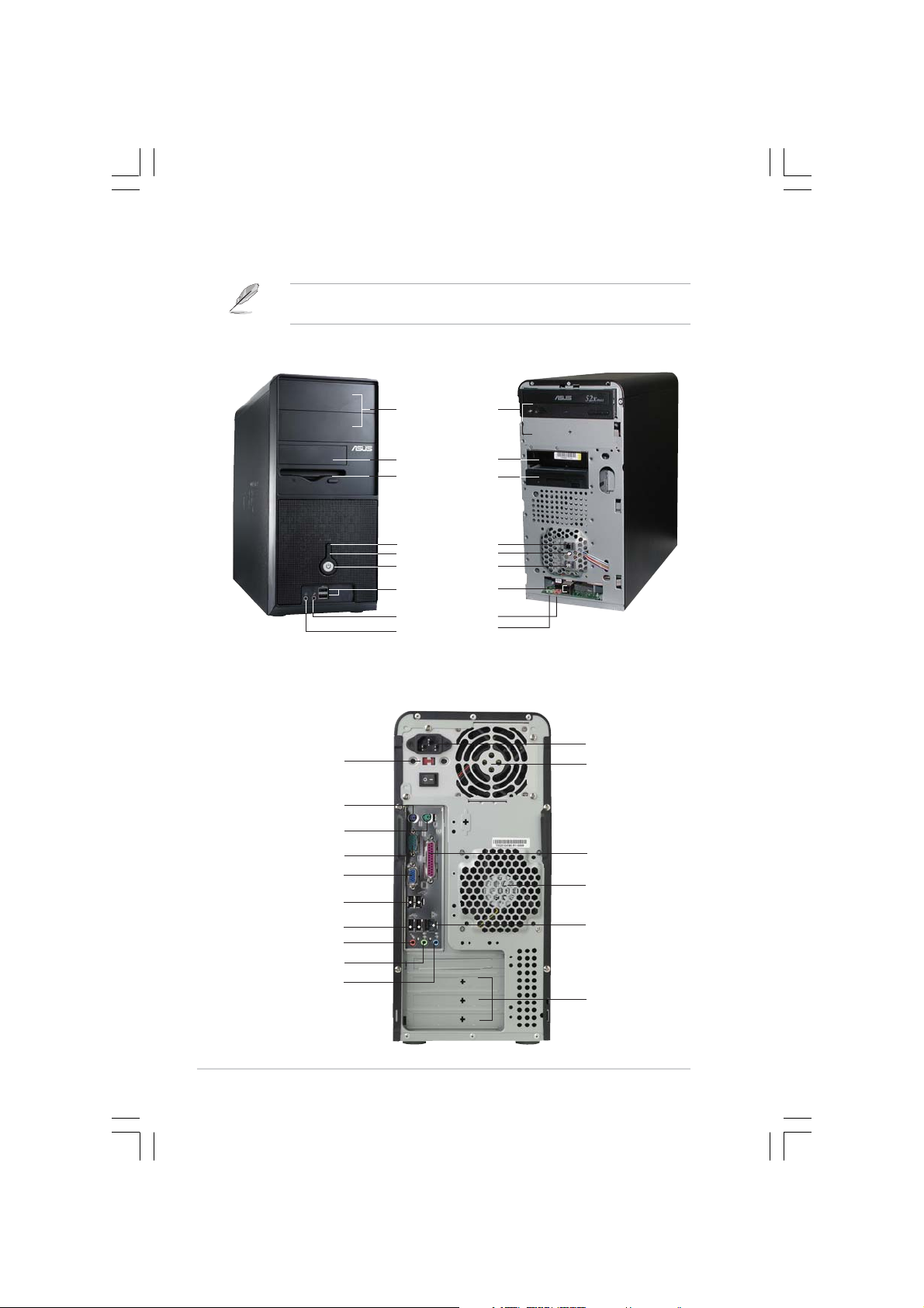
Front panel features
NOTE. NOTE.
NOTE. The photos in this guide are for reference only. For detailed
NOTE. NOTE.
information on your system’s specifications, refer to the user guide.
ExternalExternal
External
ExternalExternal
5.25-inch bays5.25-inch bays
5.25-inch bays
5.25-inch bays5.25-inch bays
(drive not(drive not
(drive not
(drive not(drive not
included)included)
included)
included)included)
HDD bayHDD bay
HDD bay
HDD bayHDD bay
FDD bayFDD bay
FDD bay
FDD bayFDD bay
(drive not(drive not
(drive not
(drive not(drive not
included)included)
included)
included)included)
Reset buttonReset button
Reset button
Reset buttonReset button
HDD LEDHDD LED
HDD LED
HDD LEDHDD LED
Power buttonPower button
Power button
Power buttonPower button
USB 2.0 portsUSB 2.0 ports
USB 2.0 ports
USB 2.0 portsUSB 2.0 ports
Microphone portMicrophone port
Microphone port
Microphone portMicrophone port
Headphone portHeadphone port
Headphone port
Headphone portHeadphone port
Rear panel features
Voltage selectorVoltage selector
Voltage selector
Voltage selectorVoltage selector
PS/2 keyboard portPS/2 keyboard port
PS/2 keyboard port
PS/2 keyboard portPS/2 keyboard port
PS/2 mouse portPS/2 mouse port
PS/2 mouse port
PS/2 mouse portPS/2 mouse port
Serial portSerial port
Serial port
Serial portSerial port
VGA portVGA port
VGA port
VGA portVGA port
USB 2.0 portsUSB 2.0 ports
USB 2.0 ports
USB 2.0 portsUSB 2.0 ports
USB 2.0 portsUSB 2.0 ports
USB 2.0 ports
USB 2.0 portsUSB 2.0 ports
Microphone portMicrophone port
Microphone port
Microphone portMicrophone port
Line Out portLine Out port
Line Out port
Line Out portLine Out port
Line In portLine In port
Line In port
Line In portLine In port
InternalInternal
Internal
InternalInternal
Power socketPower socket
Power socket
Power socketPower socket
Power supplyPower supply
Power supply
Power supplyPower supply
modulemodule
module
modulemodule
Parallel portParallel port
Parallel port
Parallel portParallel port
Chassis fan ventChassis fan vent
Chassis fan vent
Chassis fan ventChassis fan vent
LL
AN (RJ-45) portAN (RJ-45) port
L
AN (RJ-45) port
LL
AN (RJ-45) portAN (RJ-45) port
Expansion slotsExpansion slots
Expansion slots
Expansion slotsExpansion slots
iiii
ii
iiii
Page 3
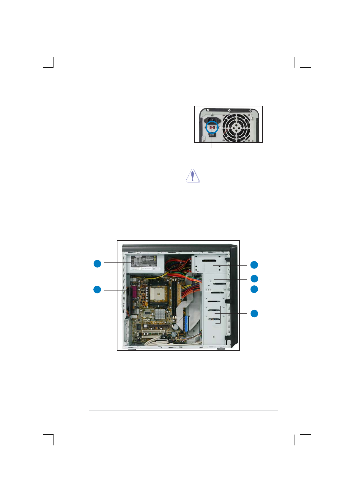
Voltage selector
The switching power supply that came
with the system has a voltage selector
switch below the power socket. Use this
switch to select the appropriate voltage
according to the voltage supply in your
area.
If the voltage supply in your area is
100-127V, set the switch to 115V.
If the voltage supply in your area is
200-240V, set the switch to 230V.
Internal components
11
1
11
115V/230V115V/230V
115V/230V
115V/230V115V/230V
Voltage selectorVoltage selector
Voltage selector
Voltage selectorVoltage selector
CAUTION. CAUTION.
CAUTION. Setting the
CAUTION. CAUTION.
switch to 115V in a 230V
environment will seriously
damage the system!
33
3
33
22
2
22
1. PFC power supply
2. Motherboard
3. Two 5.25” optical drive bays
4. 3.5” HDD drive bay
5. 3.5” Floppy drive bay
6. Hard disk drive bays
44
4
44
55
5
55
66
6
66
iiiiii
iii
iiiiii
Page 4

Removing the side plate and front cover
11
1
11
ScrewScrew
Screw
ScrewScrew
22
2
22
Remove the two screws on the rear
panel.
33
3
33
Side lock tabSide lock tab
Side lock tab
Side lock tabSide lock tab
Release the side lock tabs.
IMPORTANT. IMPORTANT.
IMPORTANT. Repeat
IMPORTANT. IMPORTANT.
steps 1 and 2 to remove
the other side plate.
44
4
44
Hinge-like tabHinge-like tab
Hinge-like tab
Hinge-like tabHinge-like tab
Swing the left edge of the front
panel outward, then unhook the
hinge-like tabs from the holes on
the right side of the front panel.
iviv
iv
iviv
Page 5

Installing a CPU
0
CAUTION.CAUTION.
CAUTION. Incorrect installation of the CPU into the socket may bend
CAUTION.CAUTION.
the pins and severely damage the CPU!
11
1
11
22
2
22
Socket LeverSocket Lever
Socket Lever
Socket LeverSocket Lever
Lift up the socket lever to a
90°-100° angle.
90 -10
Small triangleSmall triangle
Small triangle
Small triangleSmall triangle
Position the CPU above the socket
such that the CPU corner with the
gold triangle matches the socket
corner with a small triangle.
Installing system memory
22
2
22
11
1
11
DIMM notchDIMM notch
DIMM notch
DIMM notchDIMM notch
Gold triangleGold triangle
Gold triangle
Gold triangleGold triangle
11
1
11
Socket breakSocket break
Socket break
Socket breakSocket break
CAUTION.CAUTION.
CAUTION. A DDR DIMM is keyed with a notch so that it fits in only one
CAUTION.CAUTION.
direction. DO NOT force a DIMM into a socket to avoid damaging the
DIMM.
vv
v
vv
Page 6

Installing the fan and heatsink assembly
• The retention module base is already installed on the motherboard
upon purchase. You do not have to remove the retention module
base when installing the CPU or installing other motherboard
components.
• If you purchased a separate CPU heatsink and fan assembly, make
sure that a Thermal Interface Material is properly applied to the CPU
heatsink or CPU before you install the heatsink and fan assembly.
11
1
11
22
2
22
RetentionRetention
Retention
RetentionRetention
Module BaseModule Base
Module Base
Module BaseModule Base
33
3
33
Retention bracketRetention bracket
Retention bracket
Retention bracketRetention bracket
Retention bracket lockRetention bracket lock
Retention bracket lock
Retention bracket lockRetention bracket lock
Align the other end of the
retention bracket to the
retention module base. A clicking
sound denotes that the retention
bracket is in place.
IMPORTANT. IMPORTANT.
IMPORTANT. Do not forget to connect the CPU fan connector!
IMPORTANT. IMPORTANT.
Hardware monitoring errors can occur if you fail to plug this connector.
vivi
vi
vivi
Attach one end of the
retention bracket to the
retention module base.
44
4
44
Push down the retention
bracket lock on the retention
mechanism to secure the
heatsink and fan to the module
base.
Page 7

Installing an optical drive
11
1
11
1
11
11
Remove the drive bay plate.
44
4
33
3
33
44
Audio cable Audio cable
Audio cable
Audio cable Audio cable
Installing a hard disk drive
HDD labelHDD label
HDD label
HDD labelHDD label
sideside
side
sideside
11
1
11
22
2
22
IDE ribbon cableIDE ribbon cable
IDE ribbon cable
IDE ribbon cableIDE ribbon cable
Red stripe to pin 1Red stripe to pin 1
Red stripe to pin 1
Red stripe to pin 1Red stripe to pin 1
Power cable Power cable
Power cable
Power cable Power cable
33
3
33
Primary IDE connectorPrimary IDE connector
Primary IDE connector
Primary IDE connectorPrimary IDE connector
44
4
44
Connect the blue interface of the IDE ribbon cable
to the primary IDE connector (blue connector
labeled PRI_IDE1) on the motherboard.
22
2
22
IDE ribbon cableIDE ribbon cable
IDE ribbon cable
IDE ribbon cableIDE ribbon cable
Power cable Power cable
Power cable
Power cable Power cable
viivii
vii
viivii
Page 8

Replacing the side plate and front cover
1
2
Side lock tabSide lock tab
Side lock tab
Side lock tabSide lock tab
Snap the side lock tabs to secure
Hinge-like tabHinge-like tab
Hinge-like tab
Hinge-like tabHinge-like tab
3
the front panel.
4
ScrewScrew
Screw
ScrewScrew
viiiviii
viii
viiiviii
Drive in two screws on the rear
panel.
IMPORTANT. IMPORTANT.
IMPORTANT. Repeat steps 3 and 4 to replace the other side plate.
IMPORTANT. IMPORTANT.
 Loading...