

Page 1

A7N8X-XE
User Guide
Motherboard
Page 2

E2126
First Edition
July 2005
Copyright © 2005 ASUSTeK COMPUTER INC. All Rights Reserved.
No part of t his manua l, i ncl udi ng t he products and s oft war e de scr ibe d in it, ma y be
reproduced, transmitted, transcribed, stored in a retrieval system, or translated into any
language in any form or by any means, except documentation kept by the purchaser for
backup purposes, without the express written permission of ASUSTeK COMPUTER INC. (“
ASUS”).
Product warranty or service will not be extended if: (1) the product is repaired, modified or
altered, unless such repair, modification of alteration is authorized in writing by ASUS; or (2)
the serial number of the product is defaced or missing.
ASUS PROVIDES THIS MANUAL “AS IS” WITHOUT WARRANTY OF ANY KIND, EITHER
EXPRESS OR IMPLIED, INCLUDING BUT NOT LIMITED TO THE IMPLIED WARRANTIES
OR CONDITIONS OF MERCHANTABILITY OR FITNESS FOR A PARTICULAR PURPOSE.
IN NO EVENT SHALL ASUS, ITS DIRECTORS, OFFICERS, EMPLOYEES OR AGENTS BE
LIABLE FOR ANY INDIRECT, SPECIAL, INCIDENTAL, OR CONSEQUENTIAL DAMAGES
(INCLUDING DAMAGES FOR LOSS OF PROFITS, LOSS OF BUSINESS, LOSS OF USE
OR DATA, INTERRUPTION OF BUSINESS AND THE LIKE), EVEN IF ASUS HAS BEEN
ADVISED OF THE POSSIBILITY OF SUCH DAMAGES ARISING FROM ANY DEFECT OR
ERROR IN THIS MANUAL OR PRODUCT.
SPECIFICATIONS AND INFORMATION CONTAINED IN THIS MANUAL ARE FURNISHED
FOR INFOR MATIONA L USE ONLY, AND AR E SUBJEC T TO CHANGE AT ANY TIME
WI THO UT NOTI CE, A ND S HOUL D NO T B E CON STR UED A S A COMM ITM ENT BY
ASUS. ASUS ASSUMES NO RESPONSIBILITY OR LIABILITY FOR ANY ERRORS OR
INACCURACIES THAT MAY APPEAR IN THIS MANUAL, INCLUDING THE PRODUCTS
AND SOFTWARE DESCRIBED IN IT.
Products and corporate names appearing in this manual may or may not be registered
trademarks or copyrights of their respective companies, and are used only for identification or
explanation and to the ownersʼ benefit, without intent to infringe.
ii
Page 3

Contents
Notices ...........................................................................................................v
Safety Information ..........................................................................................vi
About This Guide ..........................................................................................
A7N8X-XE Specifications Summary ............................................................
Chapter 1: Product Introduction
1.1 Welcome! ....................................................................................... 1-2
1.2 Package Contents ..........................................................................
1.3 Special Features ............................................................................
1.3.1 Product highlights ...........................................................
1.3.2 Innovative ASUS features ...............................................
1.4 Before You Proceed .......................................................................
1.5 Motherboard Overview ...................................................................
1.5.1 Motherboard layout .........................................................
1.5.2 Placement direction ........................................................
1.5.3 Screw holes ....................................................................
1.6 Central Processing Unit (CPU) ......................................................
1.6.1 Overview .........................................................................
1.6.2 Installing the CPU ...........................................................
1.7 System Memory .............................................................................
1.7.1 Overview .........................................................................
1.7.2 Memory configurations ....................................................
1.7.3 Installing a DIMM ...........................................................
1.7.4 Removing a DIMM .........................................................1-11
1.8 Expansion Slots ...........................................................................
1.8.1 Installing an expansion card .........................................
1.8.2 Configuring an expansion card .....................................
1.8.3 AGP slot ........................................................................
1.8.4 PCI slots ........................................................................
1.9 Jumpers .......................................................................................
1.10 Connectors ...................................................................................
1.10.1 Rear panel connectors ..................................................
1.10.2 Internal connectors .......................................................
1-2
1-2
1-2
1-4
1-5
1-6
1-6
1-7
1-7
1-8
1-8
1-8
1-9
1-9
1-9
1-11
1-12
1-12
1-12
1-14
1-14
1-15
1-17
1-17
1-18
vii
viii
iii
Page 4

Contents
Chapter 2: BIOS Setup
2.1 Managing and Updating Your BIOS ............................................... 2-2
2.1.1 Creating a bootable floppy disk .......................................
2.1.2 Using AFUDOS to copy the current BIOS .......................
2.1.3 Using AFUDOS to update the BIOS ...............................
2.1.4 ASUS CrashFree BIOS utility .........................................
2.1.5 Using ASUS EZ Flash to update the BIOS .....................
2.1.6 ASUS Update utility ........................................................
2.2 BIOS Setup Program .....................................................................
2.2.1 BIOS menu bar ...............................................................
2.2.2 Navigation keys .............................................................
2.3 Main Menu ...................................................................................
2.4 Advanced Menu ...........................................................................
2.4.1 JumperFree Configuration ............................................
2.4.2 USB ConfigurationMemory Configuration .....................
2.4.3 CPU Configuration ........................................................
2.4.4 Chipset ..........................................................................
2.4.5 Onboard Devices Configuration ....................................
2.4.6 PCIPnP .........................................................................
2.5 Power Menu .................................................................................
2.5.1 APM Configuration ........................................................
2.5.2 Hardware Monitor .........................................................
2.6 Boot Menu ....................................................................................
2.6.1 Boot Device Priority ......................................................
2.6.2 Boot Settings Configuration ..........................................
2.6.3 Security .........................................................................
2.7 Exit Menu .....................................................................................
2-2
2-3
2-3
2-5
2-6
2-7
2-9
2-8
2-10
2-12
2-15
2-15
2-16
2-17
2-17
2-21
2-22
2-23
2-24
2-26
2-27
2-27
2-28
2-29
2-31
Chapter 3: Software Support
3.1 Installing An Operating System ...................................................... 3-2
3.2 Support CD Information .................................................................
3.2.1 Running the support CD .................................................
3.2.2 Drivers menu ...................................................................
3.2.3 Utilities menu ..................................................................
3.2.4 Contacts menu ................................................................
iv
3-2
3-2
3-3
3-3
3-4
Page 5

Notices
Federal Communications Commission Statement
This device complies with FCC Rules Part 15. Operation is subject to the following
two conditions:
• This device may not cause harmful interference, and
• This device must accept any interference received including interference that
may cause undesired operation.
Th is equi p ment ha s been t e sted an d found to c omply w ith the lim its for a
Class B digital device, pursuant to Part 15 of the FCC Rules. These limits are
designed to provide reasonable protection against harmful interference in a
residential installation. This equipment generates, uses and can radiate radio
frequency energy and, if not installed and used in accordance with manufacturerʼ
s instructions, may cause harmful interference to radio communications. However,
there is no guarantee that interference will not occur in a particular installation. If
this equipment does cause harmful interference to radio or television reception,
which c an be determ ined b y turn ing th e equipmen t off and on, t he use r is
encouraged to try to correct the interference by one or more of the following
measures:
• Reorient or relocate the receiving antenna.
• Increase the separation between the equipment and receiver.
• Connect the equipment to an outlet on a circuit different from that to which
the receiver is connected.
• Consult the dealer or an experienced radio/TV technician for help.
The use of shielded cables for connection of the monitor to the graphics card is
required to assure compliance with FCC regulations. Changes or modifications
to this unit not expressly approved by the party responsible for compliance could
void the userʼs authority to operate this equipment.
Canadian Department of Communications Statement
This digital apparatus does not exceed the Class B limits for radio noise emissions
from d igital apparatu s set out i n the Radio Interfer ence Regulation s of the
Canadian Department of Communications.
This class B digital apparatus complies with Canadian ICES-003.
v
Page 6

Safety Information
Electrical safety
• To prevent electrical shock hazard, disconnect the power cable from the
electrical outlet before relocating the system.
• When adding or removing devices to or from the system, ensure that the
power cables for the devices are unplugged before the signal cables are
connected. If possible, disconnect all power cables from the existing system
before you add a device.
• Before connecting or removing signal cables from the motherboard, ensure
that all power cables are unplugged.
• Seek professional assistance before using an adapter or extension cord.
These devices could interrupt the grounding circuit.
• Make sure that your power supply is set to the correct voltage in your area.
If you are not sure about the voltage of the electrical outlet you are using,
contact your local power company.
• If the power supply is broken, do not try to fix it by yourself. Contact a
qualified service technician or your retailer.
Operation safety
• Before installing the motherboard and adding devices on it, carefully read all
the manuals that came with the package.
• Before using the product, make sure all cables are correctly connected and
the power cables are not damaged. If you detect any damage, contact your
dealer immediately.
• To avoid short circuits, keep paper clips, screws, and staples away from
connectors, slots, sockets and circuitry.
• Avoid dust, humidity, and temperature extremes. Do not place the product in
any area where it may become wet.
• Place the product on a stable surface.
• If you encounter technical problems with the product, contact a qualified
service technician or your retailer.
vi
Page 7

About This Guide
How this guide is organized
This manual contains the following parts:
• Chapter 1: Product Introduction
Th is chap ter des cribes the featu res of t he moth e rboar d and th e new
technology it supports. It also lists the hardware setup procedures that you
have to perform when installing system components. It includes description of
the jumpers and connectors on the motherboard.
• Chapter 2: BIOS Information
This chapter tells how to change system settings through the BIOS Setup
menus. Detailed descriptions of the BIOS parameters are also provided.
• Chapter 3: Software Support
This chapter describes the contents of the support CD that comes with the
motherboard package.
Conventions used in this guide
To make sure that you perform certain tasks properly, take note of the following
symbols used throughout this guide.
WARNING: Information to prevent injury to yourself when trying to
complete a task.
CAUTION: Information to prevent damage to the components when
trying to complete a task.
IMPORTANT: Information that you MUST follow to complete a task.
NOTE: Tips and additional information to aid in completing a task.
Where to find more information
Refer to the following sources for additional information and for product and
software updates.
1. ASUS websites
The ASUS websites wo rldw ide provid e upd ated inform atio n on ASU S
hardware and software products. Refer to the ASUS contact information.
2. Optional documentation
Your product package may include optional documentation, such as warranty
flyers, that may have been added by your dealer. These documents are not
part of the standard package.
vii
Page 8

A7N8X-XE Specifications Summary
CPU
Chipset
Front Side Bus (FSB)
Memory
Expansion Slots
Storage
Audio
LAN
USB
ASUS Special features
Rear panel I/O ports
Internal I/O connectors
BIOS features
Industry standard
Manageability
Socket A for AMD Athlon™ XP/Sempron™
NVIDIA® nForce 2 Ultra 400
NVIDIA® nForce 2 MCP-RAID
400/333/266 MHz
3 x 184-pin DDR DIMM Dockets for up to 3GB memory
Support DDR 400/333/266, non-ECC, un-buffered memory
Support Dual Channel Architecture
1 x AGP 8X
5 x PCI
2 x UltraDMA 133/100/66/33
2 x Serial ATA, RAID 0, RAID 1, RAID 0 + 1 support
C-Media CMI9761A 6-channel CODEC
S/PDIF out interface
Realtek RTL8201BL 10/100Mbps LAN PHY
Supports up to eight USB 2.0 ports
ASUS C.P.R.
ASUS C.O.P. (CPU Overheating Protection)
ASUS MyLogo2
SFS (Stepless Frequency Selection) from 200MHz up to
400MHz at 1MHz increment
1 x Parallel port
1 x Serial (COM1) port
1 x PS/2 Keyboard port (purple)
1 x PS/2 Mouse port (green)
1 x Audio I/O port
1 x LAN (RJ-45) port
1 x S/PDIF Out (Coaxial) port
4 x USB 2.0 ports
1 x Floppy disk drive connector
2 x IDE connectors
2 x Serial ATA connectors
2 x USB connectors supports additional 4 USB ports
20-pin ATX power connector
CD/AUX audio in connectors
CPU/Chassis FAN connectors
Front panel audio connector
4 Mb Flash ROM, AMI BIOS, PnP, DMI2.0, WfM2.0, SM
BIOS 2.3, ASUS EZ Flash, ASUS CrashFree BIOS
PCI 2.2, USB 2.0/1.1
WfM 2.0, DMI 2.0, WOL by PME, WOR by PME
Duron™ processors
/
viii
(continued next page)
Page 9

A7N8X-XE Specifications Summary
Support CD
Accessary
Form factor
* Specifications are subject to change without notice.
Drivers
ASUS PC Probe
Anti-Virus Software
ASUS LiveUpdate
Userʼs Manual
UltraDMA cable
FDD cable
I/O shield
SATA cable
ATX, 12” x 7.8” (30.5cm x 19.8cm)
ix
Page 10

x
Page 11

This chapter describes the motherboard
feature s and t h e new t e c h nologi e s it
supports.
Product
Introduction
1
Page 12

1.1 Welcome!
Thank you for buying an ASUS® A7N8X-XE motherboard!
The motherboard delivers a host of new features and latest technologies, making it
another standout in the long line of ASUS quality motherboards!
Before you start installing the motherboard, and hardware devices on it, check the
items in your package with the list below.
1.2 Package contents
Check your motherboard package for the following items.
Motherboard ASUS A7N8X-XE motherboard
Cables Serial ATA signal cable and Serial ATA power cable
Ultra DMA cable
Floppy Disk Drive cable
Accessories I/O shield
Application CDs ASUS motherboard support CD
Documentation User guide
If any of the above items is damaged or missing, contact your retailer.
1.3 Special features
1.3.1 Product highlights
400 MHz FSB Athlon XP CPU Support
The motherboard supports 400MHz front side bus frequency for AMDʼs Athlon
XP and Sempron processors allowing increased office productivity and enhanced
digital media experience. See page 1-8.
Dual-Channel DDR 400
The 128-bit TwinBank DDR Memory architecture doubles the DDR 400 (PC3200)
bandwidth. System bottlenecks are eliminated with balanced architecture and peak
bandwidths up to 6.4 GB/s. See page 1-9 for details.
1-2 Chapter 1: Product Introduction
Page 13

Serial ATA technology
Se rial ATA is the nex t gene r ation ATA sp ecific ation that prov ides sc alabl e
performance for today and tomorrow. With up to 150MB/s data transfer rate, Serial
ATA is faster than current Parallel ATA, while providing 100% software compatibility.
A7N8X-XE supports RAID 0, RAID 1 and RAID 0 + 1. See page 1-19 for details.
Integrated 10/100 LAN controller
A 10/100Mbps Fast Ethernet controller is embedded in this motherboard to give
you a fast and reliable connection to a local area network (LAN) and the Internet.
See page 1-20
Coaxial S/PDIF out
This motherboard provides convenient connectivity to external home theater audio
systems via an coaxial S/PDIF-out (SONY-PHILIPS Digital Interface) jack. it allows
to transfer digital audio without converting to analog format and keeps the best
signal quality. See page 1-17 for details.
USB 2.0 technology
USB 2.0 is the latest connectivity standard for next generation components and
peripherals. Backwards compatible with current USB 1.1 peripherals, USB 2.0
delivers transfer speeds up to 40 times faster at 480 MB/s, for easy connectivity
and ultra-fast data transfer rate. See pages1-17 & 1-20 for details.
AGP8X
AGP8X (AGP 3.0) is the mainstream VGA interface specification that enables
enhanced graphices performance with high bandwidth up to 2.13 GB/s. See page
1-14 for details.
ASUS A7N8X-XE Motherboard 1-3
Page 14

1.3.2 Innovative ASUS features
CrashFree BIOS
CrashFree BIOS allows users to restore BIOS data from a floppy diskette even
when BIOS code and data are corrupted during upgrade or invaded by virus.
Unlike other competing vendorsʼ products, ASUS motherboards now enable users
to enjoy this protection feature without the need to pay for an extra ROM. See page
2-5 for details.
ASUS EZ Flash BIOS
With ASUS EZ Flash, you can update BIOS before entering operating system. No
more DOS-based flash utility and bootable diskette required. See page 2-6 for
details.
ASUS C.O.P. (CPU Overheating Protection)
The ASUS C.O.P. (CPU Overheating Protection) is a hardware protection circuit
that automatically shuts down the system power before temperatures go high
enough to permanently damage the CPU. See page 2-26 for details.
C.P.R. (CPU Parameter Recall)
When the system hangs due to overclocking failure, there is no need to open the
case to clear CMOS data. Just simply restrart the system, the BIOS would show
the previous setting and then users can amend the CPU setting again.
ASUS MyLogo 2
You can convert your favorite photo into a 256-color boot logo for a more colorful
and vivid image on your screen.
1-4 Chapter 1: Product Introduction
Page 15

1.4 Before you proceed
Take note of the following precautions before you install motherboard components
or change any motherboard settings.
• Unplug the power cord from the wall socket before touching any
component.
• Use a grounded wrist strap or touch a safely grounded object or
a metal object, such as the power supply case, before handling
components to avoid damaging them due to static electricity
• Hold components by the edges to avoid touching the ICs on them.
• Whenever you uninstall any component, place it on a grounded
antistatic pad or in the bag that came with the component.
• Before you install or remove any component, ensure that the ATX
power supply is switched off or the power cord is detached from
the power supply. Failure to do so may cause severe damage to the
motherboard, peripherals, and/or components.
ASUS A7N8X-XE Motherboard 1-5
Page 16
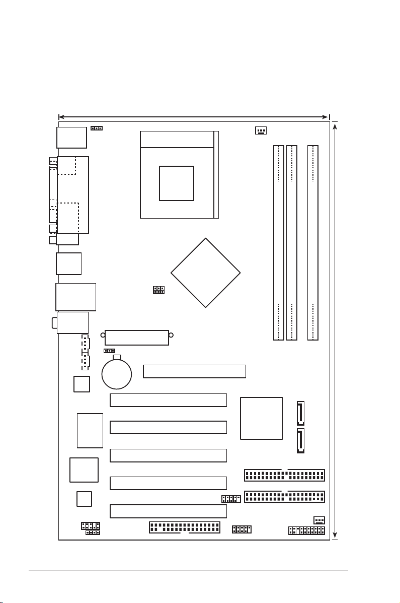
1.5 Motherboard overview
Bottom:Mic In
Center:Line Out
Top:Line In
PANEL
A7N8X-XE
CR2032 3V
Lithium Cell
CMOS Power
AUX
IDE1
ATXPWR
19.9cm (7.8in)
30.5cm (12.0in)
CPU_FAN
DDR DIMMA1 (64 bit,184-pin module)
USB34
FLOPPY
Super
I/O
4Mb
BIOS
PS/2KBMS
T: Mouse
B: Keyboard
LAN_USB12
CD
REALTEK
RTL8201BL
USB56
SATA2
MCP-RAID
CHA_FAN
Socket 462
DDR DIMMA2 (64 bit,184-pin module)
DDR DIMMB1 (64 bit,184-pin module)
nVidia nForce 2
Ultra 400
IDE2
AGP
PCI1
PCI2
PCI3
PCI4
PCI5
SATA1
USB78
PARALLEL PORT
COM1
SPDIF_O
FSB_SEL0
FSB_SEL1
PS2USBPW
CLRTC
JR1JL1
FP_AUDIO
CM19761A
1.5.1 Motherboard layout
1-6 Chapter 1: Product Introduction
Page 17
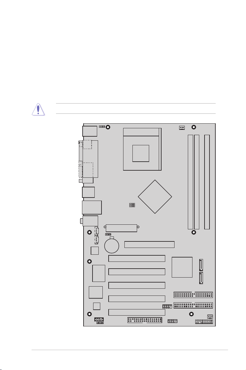
1.5.2 Placement direction
A7N8X-XE
When installing the motherboard, make sure that you place it into the chassis in the
correct orientation. The edge with external ports goes to the rear part of the chassis
as indicated in the image below.
1.5.3 Screw holes
Place seven screws into the holes indicated by circles to secure the motherboard
to the chassis.
Do not overtighten the screws! Doing so can damage the motherboard.
Place this side towards-the rear of the chassis
ASUS A7N8X-XE Motherboard 1-7
Page 18
1.6 Central Processing Unit (CPU)
A7N8X-XE
®
A7N8X-XE CPU Socket 462
AMD™ CPU
CPU NOTCH
LOCK
CPU NOTCH
TO INNER
CORNER
LEVER
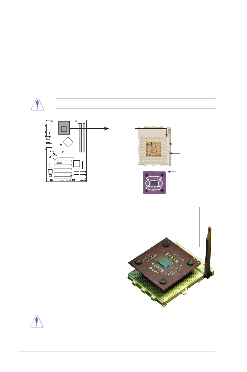
1.6.1 Overview
The motherboard has a Socket A for installation. The AMD Athlon™/Sempron™
/Duron™ CPU has a “marked” corner. This corner is usually indicated with a notch,
and/or a golden square or triangle. Refer to this indicator when orienting the CPU.
A fan and heatsink should be installed on top of the CPU to prevent overheating.
Do not use processors with core speeds of less than 1GHz.
1.6.2 Installing the CPU
Golden corner
Follow these steps to install a CPU:
1. Locate the CPU socket. Open the
socket by pulling the lever gently
sideways away from the socket,
then lift the lever upwards to a 90
to 100-degree angle.
2. Insert the CPU with the correct
o r i e n t a t i o n . Th e no t c h e d or
golden corner of the CPU must be
oriented toward the inner corner
of the socket base nearest to the
lever hinge.
1-8 Chapter 1: Product Introduction
The CPU should drop easily into place. Do not force the CPU into the socket to
avoid bending the pins. If the CPU does not fit, check its alignment and look for
bent pins.
Page 19
1.7 System memory
A7N8X-XE
®
A7N8X-XE 184-pin DDR DIMM sockets
DIMMA1
DIMMA2
DIMMB1
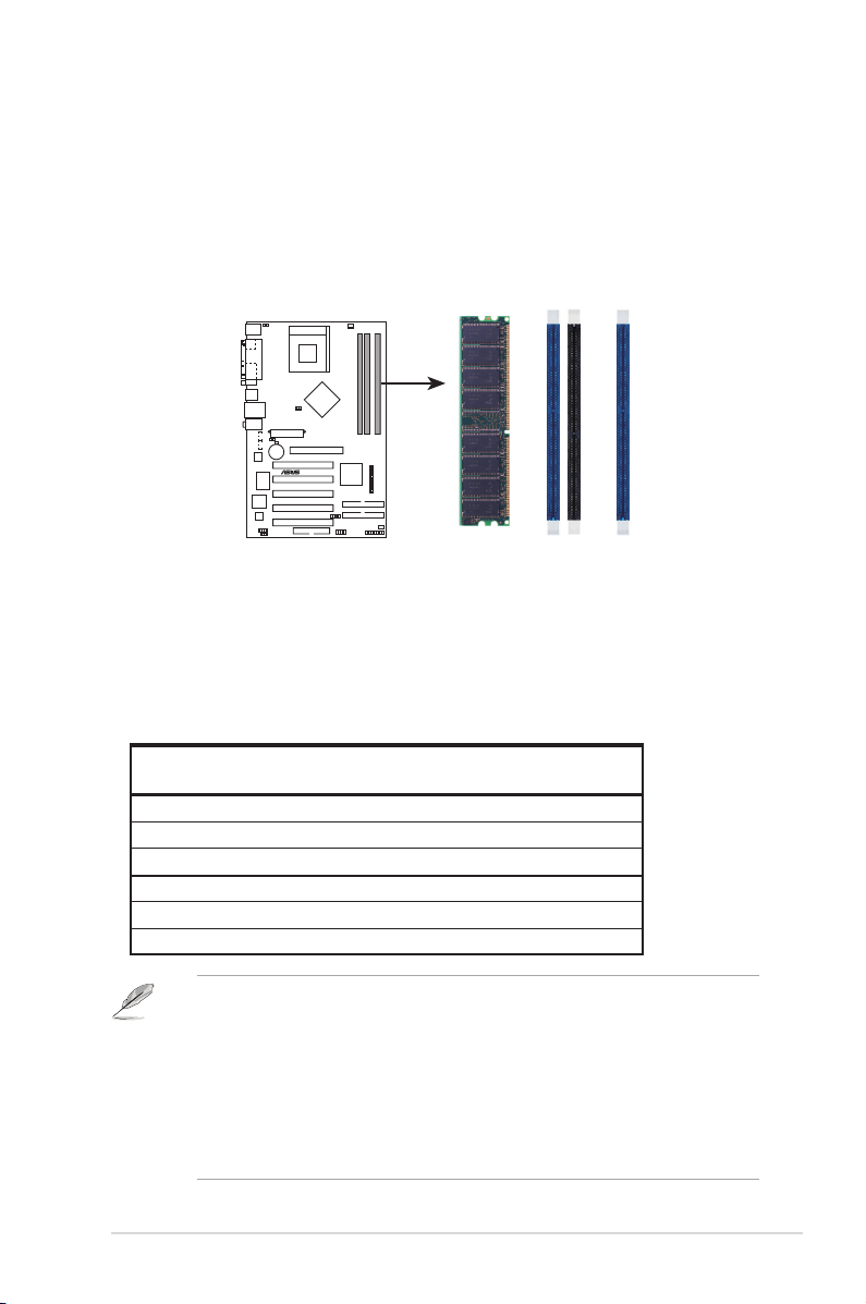
1.7.1 Overview
The motherboard has three Double Data Rate (DDR) DIMM sockets that support
up to 3 GB unbuffered non-ECC DDR400/333/266 DDR SDRAM DIMMs. Each
DIMM socket is double-sided.
1.7.2 Memory configurations
You may install single or double-sided 64 MB, 128 MB, 256 MB, 512 MB, and 1 GB
DDR DIMMs to the sockets.
Table 1 Recommended memory configurations
Sockets
Mode DIMM_A1 DIMM_A2 DIMM_B1
Single-channel (1) Populated — —
(2) — Populated —
(3) — — Populated
Dual-channel* (1) Populated — Populated
(2) — Populated Populated
(3) Populated Populated Populated
1. DIMMs with more than 8 devices on each side of the module are not supported.
2. Make sure the memory frequency and bus frequency setting in the BIOS are
the same or set to [Auto] ensure system stability.
3. A DDR DIMM is keyed with a notch so that it fits in only one direction. DO
NOT force a DIMM into a socket to avoid damaging the DIMM.
4. For optimum compatibility, it is recommended that you obtain memory
modules from qualified vendors. See the next page for a list of qualified
DDR400 DIMM vendors.
5. Visit ASUS website (www.asus.com) for latest DDR400 Qualified Vendor List.
ASUS A7N8X-XE Motherboard 1-9
Page 20

DDR400 Qualified Vendors List
Size Vendor Model CL Brand SS/DS Component DIMM socket support
256MB Kingston KVR333X64C25/256 N/A Kingston SS D3208DH1T-6 Pass Pass Pass
256MB Kingston KVR333X64C25/256 N/A Hynix SS HY5DU56822BT-J Pass Pass Pass
256MB Kingston KVR333X64C25/256 N/A Hynix DS HY5DU56822BT-D43 Pass Pass Pass
512MB Kingston KVR333X64C25/512 N/A Kingston DS D3208DH1T-6 Pass Pass -
512MB Kingston KVR333X64C25/512 N/A Hynix DS HY5DU56822BT-J Pass Pass Pass
512MB Kingston KVR400X64C3A/512 N/A Hynix DS HY5DU56822BT-D43 Pass Pass Pass
512MB Kingston KVR400X64C3A/512 N/A Kingston DS D3208DH1T-5 Pass Pass Pass
256MB Kingston KVR400X64C3A/256 N/A Hynix SS HY5DU56822BT-D43 Pass Pass -
256MB Infineon HYS64D32300GU-5-C Infineon SS HYB25D256800CE-5C Pass Pass Pass
512MB Infineon HYS64D64320GU-5-C Infineon DS HYB25D256800CE-5C Pass Pass Pass
256MB Infineon HYS64D32300GU-5-C N/A Infineon SS HYB25D256800CE-5C Pass Pass Pass
512MB Infineon HYS64D64320GU-6-C N/A Infineon DS HYB25D256800CE-6C Pass Pass Pass
256MB HY DDR400-256 N/A Hynix SS HY5DU56822BT-D43 Pass Pass Pass
512MB HY DDR400-512 N/A Hynix DS HY5DU56822BT-D43 Pass Pass Pass
256MB HY DDR333-256 N/A Hynix SS HY5DU56822BT-J Pass Pass Pass
512MB HY DDR333-512 N/A Hynix DS HY5DU56822BT-J Pass Pass -
256MB Corsair VS256MB400 N/A Value select SS VS32M8-5 2B0409 Pass Pass Pass
256MB Corsair XMS3202v3.1 Infineon SS HYB25D256807BT-5B Pass Pass Pass
512MB Corsair VS512MB400 N/A Value select DS VS32M8-5 2B0402 Pass Pass -
256MB Corsair VS256MB333 N/A Samsung SS K4H5608380-TCB3 Pass Pass Pass
512MB Corsair XMS2702v3.1 Mosel DS V58C2256804SAT6 Pass Pass Pass
512MB Corsair XMS2702v1.2 Winbond DS W942508CH-6 Pass Pass -
512MB Corsair VS512MB333 N/A Value select DS VS32M8-6 2B0412 Pass Pass -
512MB Micron MT16VDDT6464AG-335GB N/A Micron DS MT46V32M8TG-6TG Pass Pass Pass
256MB Micron MT8VDDT3264AG-335GB Micron SS MT46V32M8TG-6TG Pass Pass Pass
256MB Micron MT8VDDT3264AG-40BGB Micron SS MT46V32M8TG-5BG Pass Pass Pass
512MB Micron MT16VDDT6464AG-40BCB Micron DS MT46V32M8TG-5BC Pass Pass Pass
256MB Samsung M368L3223FTN-CCC Samsung SS K4H560838F-TCCC - - Pass
512MB Samsung M368L6423FTN-CCC Samsung DS K4H560838F-TCCC Pass Pass Pass
256MB Samsung M368L3223FTN-CB3 Samsung SS K4H560838F-TCB3 Pass Pass Pass
512MB Samsung M368L6423FTN-CB3 Samsung DS K4H560838F-TCB3 Pass Pass Pass
A*: Supports one module inserted in any slot as Single-channel memory con guration
B*: Supports one pair of modules inserted into either the blue slots or the black slots as one pair of Dualchannel memory con guration
C*: Supports 3 modules inserted into both the blue and black slots as two pairs of Dual-channel memory
con guration
(Optional)
A* B* C*
1-10 Chapter 1: Product Introduction
Page 21
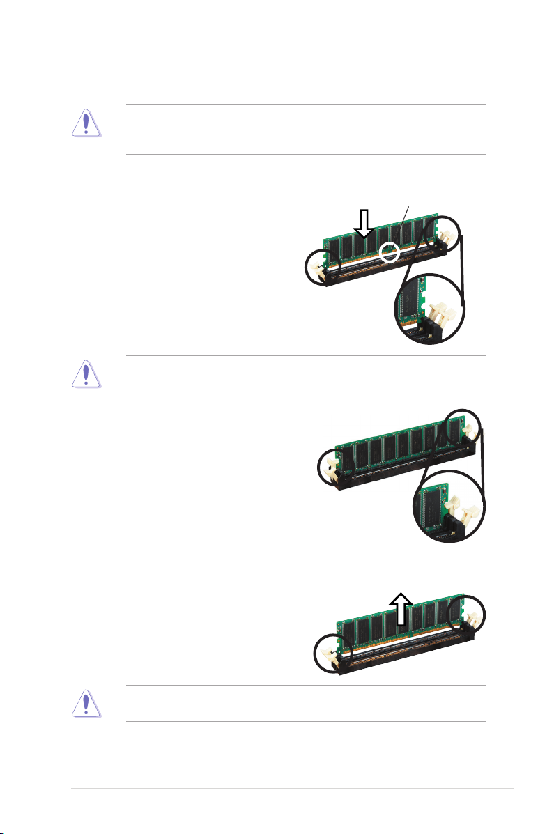
1.7.3 Installing a DIMM
Make sure to unplug the power supply before adding or removing DIMMs or
other system components. Failure to do so may cause severe damage to both
the motherboard and the components.
Follow these steps to install a DIMM.
1. L o c a t e the DIMM sock e t s in t h e
motherboard.
2. Unlock a DIMM socket by pressing
the retaining clips outward.
3. Align a DIMM on the socket such
that the notch on the DIMM matches
the break on the socket.
A DDR DIMM is keyed with a notch so that it fits in only one direction. DO NOT
force a DIMM into a socket to avoid damaging the DIMM.
4. F i rmly i n s e r t the D I M M into t h e
socket until the retaining clips snap
bac k i n pl a ce an d th e D I M M is
properly seated.
1.7.4 Removing a DIMM
Follow these steps to remove a DIMM.
DDR DIMM notch
Unlocked Retaining
Clip
Locked Retaining Clip
1. Simultaneously press the retaining
clips outward to unlock the DIMM.
Support the DIMM lightly with your fingers when pressing the retaining clips.
The DIMM might get damaged when it flips out with extra force.
2. Remove the DIMM from the socket.
ASUS A7N8X-XE Motherboard 1-11
Page 22

1.8 Expansion slots
In the future, you may need to install expansion cards. The following sub-sections
describe the slots and the expansion cards that they support.
Make sure to unplug the power cord before adding or removing expansion
cards. Failure to do so may cause you physical injury and damage motherboard
components.
1.8.1 Installing an expansion card
To install an expansion card:
1. Before installing the expansion card, read the documentation that came with
it and make the necessary hardware settings for the card.
2. Remove the system unit cover (if your motherboard is already installed in a
chassis).
3. Remove the bracket opposite the slot that you intend to use. Keep the screw
for later use.
4. Align the card connector with the slot and press firmly until the card is
completely seated on the slot.
5. Secure the card to the chassis with the screw you removed earlier.
6. Replace the system cover.
1.8.2 Configuring an expansion card
After installing the expansion card, configure it by adjusting the software settings.
1. Turn on the system and change the necessary BIOS settings, if any. See
Chapter 2 for information on BIOS setup.
2. Assign an IRQ to the card. Refer to the tables on the next page.
3. Install the software drivers for the expansion card.
1-12 Chapter 1: Product Introduction
Page 23

Standard interrupt assignments
IRQ Standard Function
0 System Timer
1 Standard 101-102-key or microsoft natural keyboard
2 Programmable interrupt controller
3 ACPI IRQ hold for PCI IRQ steering
4 Communications Port (COM1)
5 C-Media AC 97 audio device
6 Standard floppy disk controller
7 ECP printer port
8 System CMOS/Real Time Clock
9 SCI IRQ used by ACPI bus
10 ACPI IRQ holder for PCI IRQ steering
11 ACPI IRQ holder for PCI IRQ steering
12 PS/2 Mouse and Keyboard
13 Numeric Data Processor
14
15 Secondary IDE Channel
Primary IDE controller
IRQ assignments for this motherboard
A B C D
PCI slot 1 — — shared —
PCI slot 2 — — — used
PCI slot 3 used — — —
PCI slot 4 — used — —
PCI slot 5 — — shared —
When using PCI cards on shared slots, ensure that the drivers support “Share
IRQ” or that the cards do not need IRQ assignments; otherwise, conflicts will arise
between the two PCI groups, making the system unstable and the card inoperable.
ASUS A7N8X-XE Motherboard 1-13
Page 24

1.8.3 AGP slot
A7N8X-XE
®
A7N8X-XE Accelerated Graphics Port (AGP)
Keyed for 1.5v
The motherboard has an Accelerated Graphics Port (AGP) slot that supports +1.5
V 8X AGP graphics card. Note the notches on the card golden fingers to ensure
that they fit into the AGP slot.
1.8.4 PCI slots
The PCI slots support cards such as a LAN card, SCSI card, USB card, and other
cards that comply with PCI specifications. The figure shows a LAN card installed
on a PCI slot.
1-14 Chapter 1: Product Introduction
Page 25

1.9 Jumpers
A7N8X-XE
®
A7N8X-XE Clear RTC RAM
CLRTC
Normal Clear CMOS
(Default)
1 2 2 3
1. Clear RTC RAM (CLRTC)
This jumper allows you to clear the Real Time Clock (RTC) RAM in CMOS.
You can clear the CMOS memory of date, time, and system setup parameters
by erasing the CMOS RTC RAM data. The onboard button cell battery
powers the RAM data in CMOS, which include system setup information such
as system passwords.
To erase the RTC RAM:
a. Turn OFF the computer and unplug the power cord.
b. Remove the onboard battery.
c. Move the jumper cap from pins
pins 2-3 for about 5~10 seconds, then move the cap back to pins 1-2.
d. Reinstall the battery.
e. Plug the power cord and turn ON the computer.
f. Hold down the <Del> key during the boot process and enter BIOS setup
to re-enter data. Please save all data before you exist.
Except when clearing the RTC RAM, never remove the cap on CLRTC jumper
default position. Removing the cap will cause system boot failure!
1-2 (default) to pins 2-3. Keep the cap on
ASUS A7N8X-XE Motherboard 1-15
Page 26

2. PS2/USB Device Wake-up (3-pin PS2USBPW)
A7N8X-XE
PS2USBPW
A7N8X-XE PS2/USB Device Wake-up
+5V +5VSB
(Default)
1 2 2 3
This jumper allows you to enable or disable the USB/PS2 keyboard or mouse
wake-up feature. Set this jumper to +5V to wake up the computer from S1
sleep mode (CPU stopped, DRAM refreshed, system running in low power
mode) using the connected keyboard, mouse or USB devices. Set this jumper
to pins 2-3 (+5VSB) to wake up from S3 and S4 sleep modes (no power to
CPU, DRAM in slow refresh, power supply in reduced power mode).
1. This device wake-up feature requires a power supply that can provide
500mA o n th e +5 VSB lead for ea ch U SB, keyboard and m ous e
devices, otherwise, the system will not power up.
2. The total current consumed must NOT exceed the power supply
capability (+5VSB) whether under normal condition or in sleep
mode.
1-16 Chapter 1: Product Introduction
Page 27

1.10 Connectors
7
3
4
5
6
1
11
2
10
8
9
1.10.1 Rear panel connectors
1. PS/2 mouse port (green). This port is for a PS/2 mouse.
2. Parallel port. This 25-pin port connects a parallel printer, a scanner, or other
devices.
3. LAN (RJ-45) port. This port allows 10/100 Mbps connection to a Local Area
Network (LAN) through a network hub.
4. Line In port (light blue). This port connects a tape, CD, DVD player or other
audio sources. In 4/6-channel mode, the function of this port becomes
Surround (Rear Speaker) Out.
5. Line Out port (lime). This port connects a headphone or a sp eaker. In
4/6-channel mode, the function of this port becomes Front Speaker Out.
6. Microphone port (pink). This port connects a microphone. In 6-channel mode,
the function of this port becomes Bass/Center.
The functions of the Line Out, Line In, and Microphone ports change when you
select the 4 or 6-channel audio configuration as shown in the following table.
Audio 2, 4, or 6-channel configuration
Port Headset/2-channel 4-channel 6-channel
Light Blue Line In Rear Surround Rear Surround
Lime Line Out Front Speaker Out Front Speaker Out
Pink Mic In Mic In Bass/Center
7. USB 2.0 ports 1 and 2. These two 4-pin Universal Serial Bus (USB) ports are
available for connecting USB 2.0 devices.
8. USB 2.0 ports 3 and 4. These two 4-pin Universal Serial Bus (USB) ports are
available for connecting USB 2.0 devices.
9. Serial connector. This 9-pin COM1 port is for pointing devices or other serial
10. S/PDIF Coaxial out jack. This jack connects to external audio output devices
with coaxial cable connectors.
11. PS/2 keyboard port (purple). This port is for a PS/2 keyboard.
ASUS A7N8X-XE Motherboard 1-17
devices.
Page 28

1.10.2 Internal connectors
A7N8X-XE
®
A7N8X-XE Floppy disk drive connector
NOTE: Orient the red markings on
the floppy ribbon cable to PIN 1.
PIN 1
FLOPPY
A7N8X-XE
®
A7N8X-XE IDE connectors
NOTE: Orient the red markings
(usually zigzag) on the IDE
ribbon cable to PIN 1.
PRI_IDE
PIN 1
SEC_IDE
1. Floppy disk drive connector (34-1 pin FLOPPY)
This connector is for the provided floppy disk drive (FDD) signal cable. Insert
one end of the cable to this connector, then connect the other end to the
signal connector at the back of the floppy disk drive.
Pin 5 on the connector is removed to prevent incorrect cable connection when
using a FDD cable with a covered Pin 5.
2. IDE connectors (40-1 pin PRI_IDE, SEC_IDE)
Th i s co n n e c to r is f o r an Ul t r a DM A 1 3 3 si g n a l ca b l e . T h e U l t r a
DMA 133 s ignal cable has thr ee co nnectors: a bl ue co nnector f or th e
IDE c o n n ector on th e moth e r b oard, a bl a c k conn e c t or fo r an U l t r a
DMA 133 /100/66 IDE s lave device ( optical drive/h ard disk drive ), and
a gr a y co n n ecto r for an Ultr a DMA 133 / 1 00/6 6 IDE mas t e r d e v i ce
(hard disk drive). If you install two hard disk drives, you must configure
th e seco nd dri ve as a slave de vice b y sett ing it s jumpe r acco rding ly.
Refer to the hard disk documentation for the jumper settings.
• Pin 20 on the IDE connector is removed to match the covered hole on the
Ultra DMA cable connector. This prevents incorrect insertion when you
connect the IDE cable.
• Use the 80-conductor IDE cable for Ultra DMA 133/100/66 IDE devices.
1-18 Chapter 1: Product Introduction
Page 29

3. Serial ATA connectors (7-pin SATA1, SATA2)
A7N8X-XE
®
A7N8X-XE SATA connectors
SATA1
SATA2
GND
RSATA_TXP2
RSATA_TXN2
GND
RSATA
_RXN2
RSATA_RXP2
GND
GND
RSATA_TXP1
RSATA_TXN1
GND
RSATA
_RXN1
RSATA_RXP1
GND
A7N8X-XE
®
A7N8X-XE Fan connectors
CPU_FAN
CHA_FAN
GND
Rotation
+12V
GND
Rotation
+12V
These connectors are for the Serial ATA signal cables for Serial ATA hard disk
drives.
Important notes on Serial ATA
• You must install Windows
®
2000 SP4, Windows® XP SP1, Windows® 2003,
or newer OS versions before using Serial ATA hard disk drives.
• The Serial ATA interface is not supported when using Windows
operating system.
4. CPU and chassis fan connectors (3-pin CPU_FAN, CHA_FAN)
The fan connectors support cooling fans of 350 mA~740 mA (8.88 W max.) or
a total of 1 A~2.22 A (26.64 W max.) at +12V. Connect the fan cables to the
fan connectors on the motherboard, making sure that the black wire of each
cable matches the ground pin of the connector.
Do not forget to connect the fan cables to the fan connectors. Insufficient air
flow inside the system may damage the motherboard components. These are
not jumpers! Do not place jumper caps on the fan connectors!
®
98SE/Me
ASUS A7N8X-XE Motherboard 1-19
Page 30

5. USB connectors (10-1 pin USB56, USB78)
A7N8X-XE
®
A7N8X-XE USB 2.0 connectors
USB56
USB+5V
USB_P6-
USB_P6+
GND
NC
USB+5V
USB_P5-
USB_P5+
GND
1
USB78
USB+5V
USB_P8-
USB_P8+
GND
NC
USB+5V
USB_P7-
USB_P7+
GND
1
A7N8X-XE
®
A7N8X-XE Internal audio connectors
AUX
(white)
CD
(black)
Right Audio Channel
Left Audio Channel
Ground
Ground
Right Audio Channel
Left Audio Channel
Ground
Ground
These connectors are for USB 2.0 ports. Connect the USB module cable to
any of these connectors, then install the module to a slot opening at the back
of the system chassis.
The USB module is purchased separately.
Never connect a 1394 cable to the USB connectors. Doing so will damage the
motherboard!
6. Internal audio connectors (4-pin CD, AUX)
These connectors allow you to receive stereo audio input from sound sources
such as a CD-ROM, TV tuner, or MPEG card.
1-20 Chapter 1: Product Introduction
Page 31

7. Front panel audio connectors (10-1 pin FP_AUDIO)
A7N8X-XE
®
A7N8X-XE Front panel audio connector
FP_AUDIO
BLINE_OUT_L
MIC2
Line out_R
Line out_L
BLINE_OUT_R
NC
MICPWR
+5VA
AGND
A7N8X-XE
®
A7N8X-XE ATX power connectors
ATXPWR
+3.3VDC
-12.0VDC
GND
PS_ON#
GND
GND
GND
-5.0VDC
+5.0VDC
+5.0VDC
PWR_OK
+12.0VDC
+3.3VDC
+3.3VDC
GND
+5.0VDC
GND
+5.0VDC
GND
+5VSB
This connector is for the front panel audio cable. This connector supports the
front panel audio I/O ports.
8. ATX power connector (20-pin ATXPWR)
This connector is for the 20-pin ATX power supply plug. The plug from the
power supply is designed to fit this connector in only one orientation. Find the
proper orientation and push down firmly until the connector completely fit.
If you will need to replace the power supply in the future, make sure that your
new ATX 12V power supply can provide 8 A on the +12 V lead and at least 1
A on the +5 V standby lead (+5VSB). The minimum recommended wattage is
230W, or 300W for a fully configured system. The system may become unstable
and may experience difficulty powering up if the power supply is inadequate.
ASUS A7N8X-XE Motherboard 1-21
Page 32

9. System panel connector (20-pin PANEL)
A7N8X-XE
®
A7N8X-XE System panel connector
* Requires an ATX power supply.
PANEL
PLED-
PWR
+5V
Speaker
Ground
RESET
Ground
Ground
Reset
Ground
Ground
PWRS
EXTSMI
W
PLED+
HD_LED-
EXTSMI
HD_LED+
HD_LED
PLED SPEAKER
This connector supports several chassis-mounted functions.
•
System power LED (3-1 pin PLED)
This connector is for the system power LED. Connect the chassis power LED
cable to this connector. The system power LED lights up when you turn on
the system power, and blinks when the system is in sleep mode.
• System warning speaker (4-pin SPEAKER)
This connector is for the chassis-mounted system warning speaker. The
speaker allows you to hear system beeps and warnings.
• Reset button (2-pin RESET)
This connector is for the chassis-mounted reset button for system reboot
without turning off the system power.
• ATX power button/soft-off button (2-pin PWRBTN)
This connector is for the system power button. Pressing the power button
turns the system on or puts the system in sleep or soft-off mode depending
on the BIOS settings. Pressing the power switch for more than four seconds
while the system is ON turns the system OFF.
• System Management Interrupt (2-pin SMI)
This connector is for the chassis-mounted suspend switch that allows you to
manually place the system into a suspend mode, or “green” mode. When in
suspend mode, the system activity is instantly decreased to save power and
to expand the life of certain system components.
• Hard disk drive activity LED (2-pin HDLED)
This connector is for the HDD Activity LED. Connect the HDD Activity LED
cable to this connector. The IDE LED lights up or flashes when data is read
from or written to the HDD.
1-22 Chapter 1: Product Introduction
Page 33

T h i s ch a p t e r t e l l s h o w to ch a n g e
the syste m se ttings thro ugh the BIOS
Setup m e n us. D e t a i led d e s c riptio n s
of the BIOS parameters are also provided.
BIOS Setup
2
Page 34

2.1 Managing and updating your BIOS
The following utilities allow you to manage and update the motherboard Basic
Input/Output System (BIOS) setup.
1. ASUS AFUDOS (Updates the BIOS in DOS mode using a bootable floppy
disk.)
2. ASUS CrashFree BIOS (Updates the BIOS using a floppy disk when the BIOS file
fails or gets corrupted.)
3. ASUS EZ Flash (Updates the BIOS in DOS mode using a floppy disk.)
4. ASUS Update (Updates the BIOS in Windows
Refer to the corresponding sections for details on these utilities.
Save a copy of the original motherboard BIOS file to a floppy disk in case you
need to restore the BIOS in the future. Copy the original motherboard BIOS
using the ASUS Update or AFUDOS utilities.
2.1.1 Creating a bootable floppy disk
1. Do either one of the following to create a bootable floppy disk.
DOS environment
a. Insert a 1.44MB floppy disk into the drive.
b. At the DOS prompt, type
Windows® XP environment
a. Insert a 1.44 MB floppy disk to the floppy disk drive.
b. Click
Start
from the Windows® desktop, then select
c. Select the 3 1/2 Floppy Drive icon.
d. Click
File
from the menu, then select
Floppy Disk window
e. Select
Create an MS-DOS startup disk
field, then click
Start
Windows® 2000 environment
To create a set of boot disks for Windows
a. Insert a formatted, high density 1.44 MB floppy disk into the drive.
b. Insert the Windows
c. Click
d. From the
Start
, then select
Open
field, type
D:\bootdisk\makeboot a:
assuming that D: is your optical drive.
e. Press <Enter>, then follow screen instructions to continue.
2. Copy the original or the latest motherboard BIOS file to the bootable floppy disk.
format A:/S
appears.
.
®
2000 CD to the optical drive.
Run
.
®
environment.)
then press <Enter>.
Format
from the format options
®
2000:
My Computer
Format 3 1/2
. A
.
2-2 Chapter 2: BIOS Setup
Page 35

2.1.2 Using AFUDOS to copy the current BIOS
The AFUDOS.EXE utility can also be used to copy the current system BIOS
settings to a floppy or hard disk. The copy can be used as a backup in case the
system BIOS fails or gets corrupted.
1. At the DOS prompt, type the command line:
afudos /o[filename]
where “filename” can be any user-provided filename of not more than eight
alphanu mer ic characters f or the ma in filename and three alphanumeric
characters for the extension name.
Press <Enter>.
The BIOS information on the screen is for reference only. What you see on your
screen may not be exactly the same as shown.
Main filename Extension name
A:\>afudos /oMYBIOS03.rom
AMI Firmware Update Utility - Version 1.10
Copyright (C) 2002 American Megatrends, Inc. All rights reserved.
Reading flash ..... 0x0008CC00 (9%)
2. The utility will copy the current system BIOS by default to the floppy disk. Make
sure that the floppy disk is not write-protected and has enough space (at least
600KB) to store the file.
A:\>afudos /oMYBIOS03.rom
AMI Firmware Update Utility - Version 1.10
Copyright (C) 2002 American Megatrends, Inc. All rights reserved.
Reading flash ..... done
A:\>
When the BIOS copy process is complete, the utility returns to the DOS prompt.
2.1.3 Using AFUDOS to update the BIOS
The AFUDOS is a DOS-based application that lets you update the BIOS file using
a bootable floppy diskette. AFUDOS also allows you to copy the original BIOS file
to a floppy diskette.
To update the BIOS using the AFUDOS.EXE:
1. Download the latest BIOS file from the website provided by the system builder.
ASUS A7N8X-XE Motherboard 2-3
Page 36

Write the BIOS filename on a piece of paper. You need to type the exact BIOS
file name at the prompt.
2. Copy the AFUDOS.EXE utility from the support CD to the bootable floppy disk
that contains the BIOS file.
3. Boot the system from the floppy disk.
4. At the DOS prompt, type the command line:
afudos /i [filename.rom]
where [filename.rom] means the latest (or original) BIOS file that you copied to
the bootable floppy disk.
5. Press <Enter>. The screen displays the status of the update process.
The BIOS information on the screen is for reference only. What you see on your
screen may not be exactly the same as shown.
A:\>afudos /iA7N8X-XE.rom
AMI Firmware Update Utility - Version 1.10
Copyright (C) 2002 American Megatrends, Inc. All rights reserved.
Reading file ..... done
Erasing flash .... done
Writing flash .... 0x0008CC00 (9%)
DO NOT shut down or reset the system while updating the BIOS! Doing so can
cause system boot failure!
When the BIOS update process is complete, the utility returns to the DOS prompt.
A:\>afudos /iA7N8X-XE.rom
AMI Firmware Update Utility - Version 1.10
Copyright (C) 2002 American Megatrends, Inc. All rights reserved.
Reading file ..... done
Erasing flash .... done
Writing flash .... 0x0008CC00 (9%)
Verifying flash .. done
A:\>
6. Reboot the system from the hard disk.
2-4 Chapter 2: BIOS Setup
Page 37

2.1.4 ASUS CrashFree BIOS utility
The ASUS CrashFree BIOS allows you to update the BIOS file when it fails or gets
corrupted. You can update a corrupted BIOS file using a floppy disk that contains
the updated BIOS file and the AFUDOS utility.
Before using this utility, prepare the floppy disk containing the updated motherboard
BIOS. The AFUDOS.EXE utility is available from the support CD.
To update the BIOS using CrashFree BIOS:
1. Turn on the system.
2. When prompted, place the floppy disk with the updated BIOS file to the floppy
disk drive.
3. Follow the instructions in the previous section to update the BIOS.
Before using the ASUS CrashFree BIOS feature on this motherboard, you must
install an AGP or PCI VGA card to one of the expansion slots before you turn on
the computer.
ASUS A7N8X-XE Motherboard 2-5
Page 38

2.1.5 Using ASUS EZ Flash to update the BIOS
The ASUS EZ Flash feature allows you to easily update the BIOS without
having to go through the long process of booting from a floppy disk and
using a DOS-based utility. The EZ Flash is built-in the BIOS LPC chip so
it is accessible by simply pressing <Alt> + <F2> during the Power-On Self
Tests (POST).
To update the BIOS using ASUS EZ Flash:
1. Visit the system builderʼs website to download the latest BIOS file for your
motherboard and rename it to
A7N8X-XE.ROM
2. Reboot the system.
3. To launch EZ Flash, press <Alt> + <F2> during POST to display the following.
User recovery requested. Starting BIOS recovery...
Checking for floppy...
. Save the BIOS file to a floppy disk.
• If there is no floppy disk in the drive, the error message “Floppy not found!” appears.
• If the correct BIOS file is not found in the floppy disk, the error message
“A7N8X-XE.ROM not found!” is displayed.
4. Insert the floppy disk that contains the BIOS file. If the
A7N8X-XE.ROM
file
is found in the floppy disk, EZ Flash performs the BIOS update process and
automatically reboots the system when done.
DO NOT shut down or reset the system while updating the BIOS! Doing so can
cause system boot failure!
User recovery requested. Starting BIOS recovery...
Checking for floppy...
Floppy found!
Reading file “a7n8x-xe.rom”. Completed.
Start flashing...
Flashed successfully. Rebooting.
2-6 Chapter 2: BIOS Setup
Page 39

2.1.6 ASUS Update utility
The ASUS Update is a utility that allows you to manage, save, and update the
motherboard BIOS in Windows
®
environment. The ASUS Update utility allows you to:
• Save the current BIOS file
• Download the latest BIOS file from the Internet
• Update the BIOS from an updated BIOS file
• Update the BIOS directly from the Internet, and
• View the BIOS version information.
This utility is available in the support CD that comes with the motherboard package.
Installing ASUS Update
To install ASUS Update:
1. Place the support CD in the optical drive. The Drivers menu appears.
2. Click the Utilities tab, then click ASUS Update. See page 3-3 for the Utilities
screen menu.
3. The ASUS Update utility is copied to your system.
• ASUS Update requires an Internet connection either through a network or
an Internet Service Provider (ISP).
• Quit all Windows
®
applications before you update the BIOS using this utility.
Updating the BIOS through the Internet
To update the BIOS through the Internet:
1. Launch the ASUS Update utility from the Windows
> Programs > ASUS > ASUSUpdate > ASUSUpdate. The ASUS Update main
window appears.
2. S ele c t U p dat e BI O S f r o m t h e
3. Select the ASUS FTP site nearest
Internet option from the drop-down
menu, then click Next.
®
desktop by clicking Start
you to avoid network traffic, or
click Auto Select. Click Next.
ASUS A7N8X-XE Motherboard 2-7
Page 40

4. From the FTP site, select the BIOS
version that you wish to download.
Click Next.
5. Follow the screen instructions to
complete the update process.
The ASUS Update utility is
ca p a b l e of u p d a ting its e l f
through the Internet. Always
update the utility to avail all
its features.
Updating the BIOS through a BIOS file
To update the BIOS through a BIOS file:
1. Launch the ASUS Update utility from the Windows
> Programs > ASUS > ASUSUpdate > ASUSUpdate. The ASUS Update main
window appears.
2. S e lect Up d a t e BIOS fr o m a fil e
option from the drop-down menu,
then click Next.
®
desktop by clicking Start
3. Locate the BIOS file from the Open
window, then click Open.
4. Foll ow the screen instructions to
complete the update process.
2-8 Chapter 2: BIOS Setup
Page 41

2.2 BIOS setup program
This motherboard supports a programmable FLASH ROM that you can update
using the provided utility described in section “2.1 Managing and updating your
BIOS.”
Use the BIOS Setup program when you are installing a motherboard, reconfiguring
your system, or prompted to “Run Setup.” This section explains how to configure
your system using this utility.
Even if you are not prompted to use the Setup program, you can change the
configuration of your computer in the future. For example, you can enable the
security password feature or change the power manage ment settings. This
requires you to reconfigure your system using the BIOS Setup program so that
the computer can recognize these changes and record them in the CMOS RAM of
FLASH ROM.
The FLASH ROM on the motherboard stores the Setup utility. When you start up
the computer, the system provides you with the opportunity to run this program.
Press <Del> during the Power-On-Self-Test (POST) to enter the Setup utility;
otherwise, POST continues with its test routines.
If you wi s h t o en t er Se t u p a f te r PO S T, r e s ta r t t h e s y s te m by pr e s si n g
<Ctrl+Alt+Delete>, or by pressing the reset button on the system chassis. You can
also restart by turning the system off and then back on. Do this last option only if
the first two failed.
The Setup program is designed to make it as easy to use as possible. Being a
menu-driven program, it lets you scroll through the various sub-menus and make
your selections from the available options using the navigation keys.
• The default BIOS settings for this motherboard apply for most conditions to
ensure optimum performance. If the system becomes unstable after changing
any BIOS settings, load the default settings to ensure system compatibility
and stability. Select the Load Default Settings item under the Exit Menu. See
section “2.7 Exit Menu.”
• The BIOS setup screens shown in this section are for reference purposes only,
and may not exactly match what you see on your screen.
• Visit the ASUS website (www.asus.com) to download the latest BIOS file for
this motherboard.
ASUS A7N8X-XE Motherboard 2-9
Page 42

2.2.1 BIOS menu bar
The top of the screen has a menu bar with the following selections:
Us e t hi s m e nu to m a k e c h an g es to t h e ba s i c s y st e m
MAIN
configuration.
ADVANCED
POWER
BOOT
EXIT
To access the menu bar items, press the right or left arrow key on the keyboard
until the desired item is highlighted.
Use this menu to enable and make changes to the advanced
features.
Use this menu to configure and enable Power Management
features.
Use this menu to configure the default system device used to
locate and load the Operating System.
Use this menu to exit the current menu or to exit the Setup
program.
2.2.2 Navigation keys
At the bottom right corner of a menu screen are the navigation keys for that
particular menu. Use the navigation keys to select items in the menu and change
the settings.
Navigation Key(S) Function Description
Left or Right arrow
Up or Down arrow
+ (plus) and - (minus)
Select the configuration field.
<Tab>
Displays the General Help screen
<F1>
Save changes and Exit
<F10>
Jumps to the Exit menu or returns to the main menu from
<ESC>
Selects the menu item to the left or right
Moves the highlight up or down between fields
Change the configuration field and data
a sub-menu
Some of the navigation keys differ from one screen to another.
2-10 Chapter 2: BIOS Setup
Page 43

General help
In addition to the Item Help window, the BIOS setup program also provides a
General Help screen. You may launch this screen from any menu by simply
pres s i n g < F 1 > . T h e G e n e r a l H e lp screen lists the legend keys and their
corresponding functions.
Scroll bar
When a scroll bar appears to the right of a help window, it indicates that there is
more information to be displayed that will not fit in the window. Use <PgUp> and
<PgDn> or the up and down arrow keys to scroll through the entire help document.
Press <Home> to display the first page, press <End> to go to the last page. To exit
the help window, press <Enter> or <Esc>.
Sub-menu
The right pointer symbol that appears at the left
of certain parameters indicates that a sub-menu
exists for this field. A sub-menu offers additional
parameter options. To display a sub-menu, move
th e h i g h l i g h t t o t h e field and press <Enter>.
The sub-menu appears. Use the legend keys to
navigate and enter values within each sub-menu
as you would within a menu. Use the <Esc> key
to return to the main menu. Take some time to
familiarize yourself with the legend keys and their
co rresp onding functi ons. P ractic e navig ating
through the various menus and sub-menus. While
moving around through the Setup program, note
that explanations appear in the Item Help window
located to the right of each menu. This window
displays the help text for the highlighted field.
System Time
System Date
Legacy Diskette A
Legacy Diskette B
Primary IDE Master
Primary IDE Slave
Secondary IDE Master
Secondary IDE Slave
Third IDE Master
Fourth IDE Master
System Information
v02.58 (C)Copyrigh
Saving changes and exiting the Setup program
See “2.7 Exit menu” for detailed information on saving changes and exiting the
setup program.
ASUS A7N8X-XE Motherboard 2-11
Page 44

2.3 Main menu
When you enter the BIOS Setup program, the Main menu screen appears, giving
you an overview of the basic system information.
System Time [13:15:30]
System Date [Mon 05/16/2005]
Legacy Diskette A [1.44M, 3.5 in.]
Legacy Diskette B [Disabled]
Primary IDE Master : [WDC WD2500JB-00FUA]
Primary IDE Slave : [Not Detected]
Secondary IDE Master : [ASUS DVD-E616P2]
Secondary IDE Slave : [Not Detected]
Third IDE Master : [Not Detected]
Fourth IDE Master : [Not Detected]
System Information
v02.58 (C)Copyright 1985-2004, American Megatrends, Inc.
Use [ENTER], [TAB]
or [SHIFT-TAB] to
select a field.
Use [+] or [-] to
configure system Time.
Select Screen
←→
Select Item
↑↓
+- Change Field
Tab Select Field
F1 General Help
F10 Save and Exit
ESC Exit
System Time [hh:mm:ss]
Sets the system to the time that you specify (usually the current time). The format
is hour, minute, second. Valid values for hour, minute and second are Hour: (00 to
23), Minute: (00 to 59), Second: (00 to 59). Use the <Tab> key to move between
the hour, minute, and second fields.
System Date [day, mm dd yyyy]
Sets the system to the date that you specify (usually the current date). The format
is month, day, year. Valid values for month, day, and year are Month: (1 to 12),
Day: (1 to 31), Year: (1999 to 2099). Use the <Tab> key to move between the
month, day, and year fields.
Legacy Diskette A [1.44M, 3.5 in.]
Se t s t he ty pe of f l op p y dr i ve in st a ll e d. Co nf i gu r at i on op ti o ns : [ N on e ]
[ 3 6 0 K , 5. 25 i n . ] [1 . 2 M , 5. 2 5 in .] [ 7 2 0 K , 3. 5 in . ] [1 . 4 4 M , 3. 5 in .]
[2.88M, 3.5 in.]
Legacy Diskette B [Disabled]
Se t s t he ty pe of f l op p y dr i ve in st a ll e d. Co nf i gu r at i on op ti o ns : [ N on e ]
[ 3 6 0 K , 5. 25 i n . ] [1 . 2 M , 5. 2 5 in .] [ 7 2 0 K , 3. 5 in . ] [1 . 4 4 M , 3. 5 in .]
[2.88M, 3.5 in.]
2-12 Chapter 2: BIOS Setup
Page 45

Primary and Secondary IDE Master/Slave; Third
and Fourth IDE Master
While entering Setup, BIOS auto-detects the presence of IDE devices. There is a
separate sub-manu for each IDE device. Select a device item then press Enter to
display the IDE device information.
Primary IDE Master
Device :Hard Disk
Vendor :WDC WD2500JB-00FUA0
Size :250.0GB
LBA Mode :Supported
Block Mode :16Sectors
PTO Mode :4
Async DMA :MultiWord DMA-2
Ultra DMA :Ultra DMA-5
SMART Monitoring:Supported
Type [Auto]
LBA/Large Mode [Auto]
Block (Multi-Sector Transfer) M [Auto]
PIO Mode [Auto]
DMA Mode [Auto]
SMART Monitoring [Auto]
32Bit Data Transfer [Disabled]
v02.58 (C)Copyright 1985-2004, American Megatrends, Inc.
Select the type
of device connected
to the system.
Select Screen
←→
Select Item
↑↓
+- Change Option
F1 General Help
F10 Save and Exit
ESC Exit
The BIOS automatically detects the values opposite the dimmed items (Device,
Vendor, Size, LBA Mode, Block Mode, PIO Mode, Async DMA, Ultra DMA, and
SMART monitoring). These values are not user-configurable. These items show
N/A if no IDE device is installed in the system.
Type [Auto]
Selects the type of IDE drive. Setting to Auto allows automatic selection of the
appropriate IDE device type. Select CDROM if you are specifically configuring a
CD-ROM drive. Select ARMD (ATAPI Removable Media Device) if your device
is either a ZIP, LS-120, or MO drive. Configuation options: [Not Installed] [Auto]
[CDROM] [ARMD]
LBA/Large Mode [Auto]
Enables or disables the LBA mode. Setting to Auto enables the LBA mode if the
device supports this mode, and if the device was not previously formatted with LBA
mode disabled. Configuration options: [Disabled] [Auto]
Block (Multi-sector Transfer) M [Auto]
Enables or disables data multi-sectors transfers. When set to Auto, the data
transfer from and to the device occurs multiple sectors at a time if the device
supports multi-sector transfer feature. When set to [Disabled], the data transfer
from a nd to the device occur s one sector at a time. Confi guratio n opt ions:
[Disabled] [Auto]
ASUS A7N8X-XE Motherboard 2-13
Page 46

PIO Mode [Auto]
Selects the PIO mode. Configuration options: [Auto] [0] [1] [2] [3] [4]
DMA Mode [Auto
]
Selects the DMA mode. Configuration options: [Auto] [SWDMA0] [SWDMA1]
[SWDMA2] [MWDMA0] [MWDMA1] [MWDMA2] [UDMA0] [UDMA1] [UDMA2]
[UDMA3] [UDMA4] [UDMA5]
If the hard disk supports DMA6, UDMA6 will appears in the configuration options.
SMART Monitoring [Auto]
Sets the Self-Monitoring, Analysis, and Reporting Technology. Configuration
options: [Auto] [Disabled] [Enabled]
32Bit Data Transfer [Disabled]
Enables or disables 32-bit data transfer. Configuration options: [Disabled] [Enabled]
System Information
This menu gives you an overview of the general system specifications. The BIOS
automatically detects the items in this menu.
BIOS SETUP UTILITY
AMIBIOS
Version : 08.00.12
Build Date: 06/02/05
Processor
Type : AMD Athlon(tm) XP 2500+
Speed : 1833HAz
Count : 1
System Memory
Size : 256MB
Select Screen
←→
Select Item
↑↓
F1 General Help
F10 Save and Exit
ESC Exit
v02.58 (C)Copyright 1985-2004, American Megatrends, Inc.
AMI BIOS
Displays the auto-detected BIOS information.
Processor
Displays the auto-detected CPU specification.
System Memory
Displays the auto-detected system memory.
2-14 Chapter 2: BIOS Setup
Page 47

2.4 Advanced menu
The Advanced menu items allow you to change the settings for the CPU and other
system devices.
Take caution when changing the settings of the Advaced menu items.
Incorrect field values can cause the system to malfunction.
BIOS SETUP UTILITY
JumperFree Configuration
USB Configuration
CPU Configuration
Chipset
Onboard Devices Configuration
PCIPnP
v02.58 (C)Copyright 1985-2004, American Megatrends, Inc.
Adjust system
frequency/voltage
←→
↑↓
+- Change Field
Enter Go to Sub Screen
F1 General Help
F10 Save and Exit
ESC Exit
2.4.1 JumperFree Configuration
BIOS SETUP UTILITY
Select the target CPU
AI Overclock Tuner [Auto]
CPU Frequency [166]
FSB Spread Spectrum [Disabled]
AGP Spread Spectrum [Disabled]
frequency, and the
relevant parameters
will be auto-adjusted.
Frequencies higer
than CPU manufacturer
recommends are not
guaranted to be
stable. If the system
becomes unstable,
return to the default.
←→
↑↓
+- Change Option
F1 General Help
F10 Save and Exit
ESC Exit
Select Screen
Select Item
Select Screen
Select Item
v02.58 (C)Copyright 1985-2004, American Megatrends, Inc.
AI Overclock Tuner [Auto]
Allows selection of CPU overclocking options to achieve desired CPU internal
frequency. Select either one of the preset overclocking options and the relevant
parameters will appear. Configuration options: [Auto] [Manual]
ASUS A7N8X-XE Motherboard 2-15
Page 48

CPU Frequency [166]
Allows you to set the CPU host frequency. Range: 100MHz-300MHz.
FSB Spread Spectrum [Disabled]
Allows you to enable and disable the FSB clock generator spread spectrum.
Configuration options: [Auto] [Disabled]
AGP Spread spectrum
[Disabled]
Allows you to enable and disable the AGP clock generator spread spectrum.
Configuration options: [Auto] [Disabled]
2.4.2 USB Configuration
The USB Configuration menu allows you to adjust the settings for the onboard USB
controllers. Select an item then press <Enter> to display the sub-menu.
BIOS SETUP UTILITY
USB Configuration To enable or disable
USB Devices Enabled:
None
USB Controller [Enabled]
USB 2.0 Support [Enabled]
Legacy USB Support [Auto]
v02.58 (C)Copyright 1985-2004, American Megatrends, Inc.
the onboard USB
controllers.
Select Screen
←→
Select Item
↑↓
+- Change Option
F1 General Help
F10 Save and Exit
ESC Exit
USB Controller [Enabled]
Allows you to enable or disable the integrated USB controller. Configuration
options: [Enabled] [Disabled]
USB 2.0 Support [Enabled]
Configuration options: [Enabled] [Disabled]
Legacy USB Support [Auto]
Allows you to enable or disable support for legacy USB devices. Configuration
options: [Enabled] [Disabled] [Auto]
2-16 Chapter 2: BIOS Setup
Page 49

2.4.3 CPU Configuration
This menu displays the CPU type, speed, cache RAM, and current front side bus
frequency auto-detected by the BIOS.
BIOS SETUP UTILITY
Processor
Type :AMD Athlon(tm) XP 2500+
Speed :1833MHz
Count :1
L1 Cache Size :64KB
L2 Cache Size :512KB
CPU Configuration
CPU Internal Cache [Disabled]
v02.58 (C)Copyright 1985-2004, American Megatrends, Inc.
Options
Disabled
Write-Thru
Write-Back
Select Screen
←→
Select Item
↑↓
+- Change Option
F1 General Help
F10 Save and Exit
ESC Exit
CPU Internal Cache [Disabled]
Allows you to enable and disable the CPU Internal Cache. Configuration options:
[Disabled] [Write-Thru] [Write-Back]
2.4.4 Chipset
The Chipset menu allows you to change the advanced chipset settings. Select an
item then press <Enter> to display the sub-menu.
BIOS SETUP UTILITY
NVIDIA nForce2 Chipset Configuration Options for NB
NorthBridge Configuration
SouthBridge Configuration
Select Screen
←→
Select Item
↑↓
Enter Go to Sub Screen
F1 General Help
F10 Save and Exit
ESC Exit
v02.58 (C)Copyright 1985-2004, American Megatrends, Inc.
ASUS A7N8X-XE Motherboard 2-17
Page 50

NorthBridge Chipset Configuration
BIOS SETUP UTILITY
Northbridge Chipset configuration This will switch the
Primary Graphices Adapter [PCI]
Graphics Aperture Size [ 64MB]
MDA Access Control [PCI]
TV Mode Support [Default]
C1 Disconnect [Auto Mode]
System Clock Settings
System Performance Settings
v02.58 (C)Copyright 1985-2004, American Megatrends, Inc.
PCI Bus scanning order
while searching for
video card.
This allows to select
the type of Primary
VGA in case of
multiple video
controllers.
Select Screen
←→
Select Item
↑↓
+- Change Option
F1 General Help
F10 Save and Exit
ESC Exit
Primary Graphices Adapter [PCI]
Allows selection of the graphics controller to use as a primary boot device.
Configuration options: [PCI] [AGP]
Graphics Aperture Size [64MB]
Allows y o u to sel e c t the s i z e of ma p p e d memory for A G P graphi c data.
Configuration options: [Disabled] [32MB] [64MB] [128MB] [256MB] [512MB]
MDA Access Control [PCI]
Allows you to control MDA Access. Configuration options: [PCI] [AGP]
TV Mode Support [Default]
Configuration options: [NTSC-M] [NTSC-J] [PAL-M] [PAL-BDGHI] [PAL-N] [PALNC] [Default]
C1 Discounnect [Auto Mode]
Configuration options: [Enabled] [Disabled] [Auto Mode]
2-18 Chapter 2: BIOS Setup
Page 51

System Performance Settings
BIOS SETUP UTILITY
System Clock Settings Memory Clock can be
Memory Clock [Auto]
DRAM Timing [Auto]
TRAS [7]
TRCD [4]
TRP [2]
CAS# Latency [Auto]
v02.58 (C)Copyright 1985-2004, American Megatrends, Inc.
set by the code using
AUTO, or you can set
one of the standard
values.
Select Screen
←→
Select Item
↑↓
+- Change Option
F1 General Help
F10 Save and Exit
ESC Exit
Memory Clock [Auto]
Allows you to set the Memory Clock. Configuration options: [Auto] [133MHz
(DDR266)] [166MHz (DDR333)] [200MHz (DDR400)]
DRAM Timing [Auto]
Allows you to set the DRAM Timing. Configuration options: [Auto] [Manual]
TRAS [7]
Allows you to set the TRAS. Range: 2-15
TRCD [4]
Allows you to set the TRCD. Range: 2-7
TRP [2]
Allows you to set the TRP. Range: 2-7
CAS# Latency [Auto]
Configuration options: [Auto] [2.0] [2.5] [3.0]
ASUS A7N8X-XE Motherboard 2-19
Page 52

South Bridge Chipset Configuration
BIOS SETUP UTILITY
South Bridge Chipset configuration Enable or Disable
Onboard LAN [Enabled]
MAC Bridge Mode [Enabled]
AC97 Audio [Auto]
Modem CODEC Interface [Auto]
OnBoard SATA Controller [Enabled]
SATA Operation Mode [non-RAID]
SMBus Interface [Enabled]
IOAPIC [Enabled]
v02.58 (C)Copyright 1985-2004, American Megatrends, Inc.
Onboard LAN device
Select Screen
←→
Select Item
↑↓
+- Change Option
F1 General Help
F10 Save and Exit
ESC Exit
Onboard LAN [Enabled]
Allows you to enable and disable the Onboard LAN. Configurati on options:
[Enabled] [Disabled]
MAC Bridge Mode [Auto]
Allows you to enable and disable the MAC Bridge Mode. Configuration options:
[Enabled] [Disabled]
AC97 Audio [Auto]
Allows you to enable and disable the AC97 Audio. Configuration options: [Enabled]
[Disabled] [Auto]
Modem CODEC Interface [Auto]
Allows you to enable and disable the Modem CODEC Interface. Configuration
options: [Enabled] [Disabled] [Auto]
OnBoard SATA Controller [Enabled]
Allows you to enable and disable the OnBoard SATA Controller. Configuration
options: [Enabled] [Disabled]
SATA Operation Mode [non-RAID]
Allows you to set the SATA Operation Mode. Configuration options: [non-RAID]
[RAID]
SMBus Interface [Enabled]
Allows you to enable and disable the SMBus Interface. Configuration options:
[Enabled] [Disabled]
IOAPIC [Enabled]
Allows you to enable and disable the IOAPIC. Configuration options: [Enabled]
[Disabled]
2-20 Chapter 2: BIOS Setup
Page 53

2.4.5 Onboard Devices Configuration
The Onboard Devices Configuration menu allows you to adjust the settings for onboard
devices. Select an item then press <Enter> to display the sub-menu.
BIOS SETUP UTILITY
Configure Win627 Super IO Chipset Allows BIOS to Enable
Onboard Floppy Controller [Enabled]
Serial Port1 Address [3F8/IRQ4]
Parallel Port Address [378]
Parallel Port Mode [ECP+EPP]
EPP Version [1.9]
ECP Mode DMA Channe1 [DMA3]
Parallel Port IRQ [IRQ7]
v02.58 (C)Copyright 1985-2004, American Megatrends, Inc.
or Disable Floppy
Controller.
Select Screen
←→
Select Item
↑↓
+- Change Option
F1 General Help
F10 Save and Exit
ESC Exit
Onboard Floppy Controller [Enabled]
Allows you to enable or disable the onboard Floppy controller. Configuration
options: [Disabled] [Enabled]
Serial Port1 Address [3F8/IRQ4]
Allows you to select the Serial Port 1 base addr ess. Configuration options:
[Disabled] [3F8/IRQ4] [2F8/IRQ3] [3E8/IRQ4] [2E8/IRQ3]
Parallel Port Address [378]
Allows you to select the Parallel Port base addresses. Configuration options:
[Disabled] [378] [278]
Parallel Port Mode [ECP+EPP]
Allows you to select the Parallel Port mode. Configuration options: [Normal] [BiDirectional] [ECP+EPP]
EPP Version [1,9]
Allo w s s e l e c t i o n of the Parallel Port EPP v e r s i o n . This item appears
on l y wh e n the Pa r a l l e l Po r t Mo d e i s se t to [E P P ] or [E P P + E C P.
Configuration options: [1.9] [1.7]
ECP Mode DMA Channel [DMA3]
Al l o w s yo u to se t th e Par al l e l Po r t ECP DMA . T hi s it e m a p p e a r s
on l y whe n th e Pa r a l l el P o r t Mo d e is se t to [E CP ] or [ E P P + E C P ] .
Configuration options: [DMA0] [DMA1] [DMA3]
Parallel Port IRQ [IRQ7]
Allows selection of the Parallel Port IRQ. Configuration options: [IRQ5] [IRQ7]
ASUS A7N8X-XE Motherboard 2-21
Page 54

2.4.6 PCIPnP
The PCIPnP menu allows you to change the settings for installed PCI devices.
Select an item then press <Enter> to display the sub-menu.
BIOS SETUP UTILITY
Advanced PCI/PnP Settings NO: lets the BIOS
WARNING: Setting wrong values in below sections
may cause system to malfunction.
Plug and Play OS [No]
PCI Latency Timer [64]
Allocate IRQ to PCI VGA [Yes]
Palette Snooping [Disabled]
IRQ-3 assigned to [PCI Device]
IRQ-4 assigned to [PCI Device]
IRQ-5 assigned to [PCI Device]
IRQ-7 assigned to [PCI Device]
IRQ-9 assigned to [PCI Device]
IRQ-10 assigned to [PCI Device]
IRQ-11 assigned to [PCI Device]
IRQ-14 assigned to [PCI Device]
IRQ-15 assigned to [PCI Device]
v02.58 (C)Copyright 1985-2004, American Megatrends, Inc.
configure all the
devices in the system.
YES: lets the
operating system
configure Plug and
Play (PnP) devices not
required for boot if
your system has a Plug
and Play operating
system
Select Screen
←→
Select Item
↑↓
+- Change Option
F1 General Help
F10 Save and Exit
ESC Exit
Plug and Play OS [No]
When set to [No], BIOS configures all devices in the system. When set to [Yes],
and if you installed a Plug and Play operating system, the operating system
configures the Plug and Play devices not required for boot. Configuration options:
[No] [Yes]
PCI Latency Timer [64]
Allows you to select the value in units of PCI clocks for the PCI device latency timer
register. Configuration options:
[32] [64] [96] [128] [160] [192] [224] [248]
Allocate IRQ to PCI VGA [Yes]
When set to [Yes], BIOS assigns an IRQ to PCI VGA card if the card requests for
an IRQ. When set to [No], BIOS does not assign an IRQ to the PCI VGA card even
if requested. Configuration options: [No] [Yes]
Palette Snooping [Disabled]
When set to [Enabled], the pallete snooping feature informs the PCI devices that
an ISA graphics device is installed in the system so that the latter can function
correctly. Setting to [Disabled] deactivates this feature. Configuration options:
[Disabled] [Enabled]
IRQ xx [PCI Device]
Allows you to set the PCI slot IRQ preference. Configuration options:
Device] [Reserved]
2-22 Chapter 2: BIOS Setup
[PCI
Page 55

2.5 Power menu
The Pow er me nu items al low you to c hang e the s etti ngs f or the A dvan ced
Power Management (APM). Select an item, then press <Enter> to display the
configuration options.
BIOS SETUP UTILITY
Select the ACPI state
Suspend Mode [Auto]
Repost Vidow on S3 Resume [No]
ACPI 2.0 Support [No]
ACPI APIC support [Enabled]
APM Configuration
Hardware Monitor
v02.58 (C)Copyright 1985-2004, American Megatrends, Inc.
Suspend Mode [Auto]
Allows you to select the (ACPI) state to be used for system suspend. Configuration
options: [S1 (POS) only] [S3 only] [Auto]
Repost Video on S3 Resume [No]
Determines whether to invoke VGA BIOS POST on S3/STR resume. Configuration
options: [No] [Yes]
used for System
Suspend.
Select Screen
←→
Select Item
↑↓
+- Change Option
F1 General Help
F10 Save and Exit
ESC Exit
ACPI 2.0 Support [Yes]
Allows you to add more tables for Advanced Configuration and Power interface
(ACPI) 2.0 specifications. Configuration options: [No] [Yes]
ACPI APIC Support [Enabled]
Allows you to enable or disable the Advanced configuration and Power interface
(ACPI) support in the Advanced Programmable Interrupt Controller (APIC). When
set to Enabled, The ACPI APIC table pointer is included in the RSDT pointer list.
Configuration options: [Disabled] [Enabled]
ASUS A7N8X-XE Motherboard 2-23
Page 56

2.5.1 APM Configuration
BIOS SETUP UTILITY
Enable or disable
Power Management/APM [Enabled]
Suspend Power Saving Type [S1]
Power Button Mode [On/Off]
Video Power Down Mode [Suspend]
Hard disk Power Down Mode [Suspend]
Manual Throttle Ratio [50%]
THRM throttle Ratio [50%]
PME Resume [Disabled]
Ring-In Power On [Disabled]
RTC Resume [Disabled]
Resume On PS/2 Keyboard [Enabled]
Resume On PS/2 Mouse [Disabled]
Restore on AC Power Loss [Power Off]
v02.58 (C)Copyright 1985-2004, American Megatrends, Inc.
Power Management/APM [Enabled]
Allows you to enable or disable the Advanced Power Management (APM) feature.
Configuration options: [Disabled] [Enabled]
Suspend Power Saving Type [S1]
Configuration options: [C2] [S1]
Power Button Mode [On/Off]
Configuration options:
[On/Off] [Suspend]
APM
Select Screen
←→
Select Item
↑↓
+- Change Option
F1 General Help
F10 Save and Exit
ESC Exit
Video Power Down Mode [Suspend]
Al l o w s you to selec t the vide o powe r dow n mod e . Con f i g u ration option s :
[Disabled] [Suspend]
Hard Disk Power Down Mode [Suspend]
Allows you to select the hard disk power down mode. Configuration options:
[Disabled] [Suspend]
Manual Throttle Ratio [50%]
Configuration options:
[87.5%] [75.0%] [62.5%] [50%] [37.5%] [25%] [12.5%]
THRM throttle Ratio [50%]
Configuration options:
2-24 Chapter 2: BIOS Setup
[87.5%] [75.0%] [62.5%] [50%] [37.5%] [25%] [12.5%]
Page 57

PME Resume [Disabled]
Configuration options: [Disabled] [Enabled]
Ring-In Power On [Disabled]
Th is fie l d allo ws you t o enabl e or dis able t h e Rin g-In Po wer on f uncti o n.
Configuration options: [Disabled] [Enabled]
RTC Resume [Disabled]
Allows you to enable or disable RTC to generate a wake event. When this item
is enabled, the Date and Resume Time fields are activated for manual setup.
Configuration options: [Disabled] [Enabled]
Resume On PS/2 Keyboard [Enabled]
Allows you to use any key on the keyboard to turn on the system. This feature
requires an ATX power supply that provides at least 1A on the +5VSB lead.
Configuration options: [Disabled] [Enabled]
Resume On PS/2 Mouse [
When set to [Enabled], this parameter allows you to use the PS/2 mouse to turn on
the system. This feature requires an ATX pwer supply that provides at least 1A on
the +5VSB lead. Configuration options: [Disabled] [Enabled]
Disabled
]
Restore on AC Power Loss [Power Off]
When set to Power Off, the system goes into off state after an AC power loss. When
set to Power On, the system goes on after an AC power loss. When set to Last State,
then system goes into either off or on state whatever the system state was before the
AC power loss. Configuration options: [Power Off] [Power On] [Last State]
ASUS A7N8X-XE Motherboard 2-25
Page 58

2.5.2 Hardware Monitor
BIOS SETUP UTILITY
Hardware Health Event Monitoring
CPU Temperature : 45ºC/113ºF
M/B Temperature : 32ºC/89ºF
CPU Fan Speed : 3863 RPM
Chassis Fan Speed : N/A
Vcore : 1.661 V
+ 3.30V : 3.403 V
+ 5.00V : 5.094 V
+ 12.00V : 11.461 V
v02.58 (C)Copyright 1985-2004, American Megatrends, Inc.
MB Temperature [xxx°C/xxx°F]
CPU Temperature [xxx°C/xxx°F]
The onboard hardware monitor automatically detects and displays the motherboard
and CPU temperatures. Seclect Disabled if you do not wish to display the detected
temperatures.
CPU Fan Speed [xxxxRPM] or [N/A]
Chassis Fan Speed [xxxxRPM] or [N/A]
The onboard hardware monitor automatically detects and displays the CPU
and chassis fan speeds in rotations per minute (RPM). If any of the fans is not
connected to the motherboard, that field shows N/A.
Select Screen
←→
Select Item
↑↓
F1 General Help
F10 Save and Exit
ESC Exit
Vcore Voltage, 3.3V Voltage, 5V Voltage, 12V Voltage
The onboard hardware monitor automatically detects the voltage output through
the onboard voltage regulators.
2-26 Chapter 2: BIOS Setup
Page 59

2.6 Boot menu
The Boot menu items allow you to change the system boot settings. Select a submenu, then press <Enter> to display the configuration options.
BIOS SETUP UTILITY
Boot Settings
Boot Device Priority
Boot Settings Configuration
Security
v02.58 (C)Copyright 1985-2004, American Megatrends, Inc.
Spedcifies the Boot
Device Proiority
sequence.
A virtual floppy disk
drive (Floppy Drive B:
) may appear when you
set the CD-ROM drive
as the first boot
device.
←→
↑↓
Enter Go to Sub Screen
F1 General Help
F10 Save and Exit
ESC Exit
2.6.1 Boot Device Priority
This menu allows you to arrange the boot device priority.
BIOS SETUP UTILITY
Boot Device Priority Specifies the boot
1st Boot Device [1st FLOPPY DRIVE]
2nd Boot Device [CDROM:SM-ASUS DVD-]
3rd Boot Device [HDD:PM-WDC WD2500J]
sequence from the
available devices.
A device enclosed in
parenthesis has been
disabled in the
correspinding type
menu.
←→
↑↓
+- Change Option
F1 General Help
F10 Save and Exit
ESC Exit
Select Screen
Select Item
Select Screen
Select Item
v02.58 (C)Copyright 1985-2004, American Megatrends, Inc.
1st ~ xxth Boot Device [Removable]
Allows you to specify the boot device priority sequence from the available devices.
The number of device items that apear on the screen depends on the number of
devices installed in the system. Configuration options: [xxxxx Drive] [Disabled]
ASUS A7N8X-XE Motherboard 2-27
Page 60

2.6.2 Boot Settings Configuration
This menu allows you to adjust the system boot settings.
BIOS SETUP UTILITY
Boot Settings Configuration Allows BIOS to skip
Quick Boot [Enabled]
Full Screen Logo [Enabled]
AddOn ROM Display Mode [Force BIOS]
Boot From Network [Disabled]
Bootup Num-Lock [On]
PS/2 Mouse Support [Auto]
Wait For ‘F1’ If Error [Enabled]
Hit ‘DEL’ Message Display [Enabled]
v02.58 (C)Copyright 1985-2004, American Megatrends, Inc.
certain tests while
booting. This will
decrease the time
needed to boot the
system.
Select Screen
←→
Select Item
↑↓
+- Change Option
F1 General Help
F10 Save and Exit
ESC Exit
Quick Boot [Enabled]
Allows you to enable or disable the system quick boot feature. When enabled, the
system skips certain tests while booting. Configuration options: [Disabled] [Enabled]
Full Screen Logo [Enabled]
Th i s a llows you to e n a b le or disabl e the f u l l screen logo d i s p lay feature.
Configuration options: [Disabled] [Enabled]
Set this item to [Enable] to use the ASUS MyLogo™ feature.
AddOn ROM Display Mode [Force BIOS]
Sets the display mode for option ROM. Configuration options: [Force BIOS] [Keep Current]
Boot From Network [Disabled]
Allows you to boot from network. Configuration options: [Disabled] [Enabled]
Bootup Num-Lock [On]
Allows you to select the power-on state for the NumLock. Configuration options:
[Off] [On]
PS/2 Mouse Support [Auto]
Allows you to enable or disable support for PS/2 mouse. Configuration options:
[Disabled] [Enabled] [Auto]
2-28 Chapter 2: BIOS Setup
Page 61

Wait for ʻF1ʼ If Error [Enabled]
When set to Enabled, the system waits for the F1 key to be pressed when error
occurs. configuration options: [Disabled] [Enabled]
Hit ʻDELʼ Message Display [Enabled]
When set to Enabled, the system displays the message “Press DEL to run Setup”
during POST. Configuration options: [Disabled] [Enabled]
2.6.3 Security
This menu allows you to adjust the system security settings.
BIOS SETUP UTILITY
Security Settings <Enter> to change
Supervisor Password :Not Installed
User Password :Not Installed
Change Supervisor Password
Change User Password
v02.58 (C)Copyright 1985-2004, American Megatrends, Inc.
password.
<Enter> again to
disable password.
Select Screen
←→
Select Item
↑↓
Enter change
F1 General Help
F10 Save and Exit
ESC Exit
Change Supervisor Password
Select this item t o set or chang e the supervisor pas swo rd. The Supervisor
Password item on top of the screen shows the default Not Installed. After you set a
password, this item shows Installed.
To set a password:
1. Select the Change Supervisor Password item and press <Enter>.
2. From the password box, type a password composed of at least six letters
and/or numbers, then press <Enter>.
3. Confirm the password when prompted.
The message “Password Installed” appears after you successfully set your
password.
To change the supervisor password, follow the same steps as in setting a user
password.
To clear the supervisor passowrd, select the Change Supervisor Password then
press <Enter>. The message “Password Uninistalled” appears.
ASUS A7N8X-XE Motherboard 2-29
Page 62

If you forget your BIOS password, you can clear it by erasing the CMOS Real TMe
Clock (RTC) RAM. See section “1.6 Jumpers” for information on how to erase the
RTC RAM.
Change User Password
Select this item to set or change the user password. The Supervisor Password item
on top of the screen shows the default Not Installed. After you set a password, this
item shows Installed.
To set a password:
1. Select the Change User Password item and press <Enter>.
2. On the password box that appears, type a password composed of at least six
letters and/or numbers, then press <Enter>.
3. Confirm the password when prompted.
The message “Password Installed” appears after you successfully set your password.
To change the user password, follow the same steps as in setting a user password.
2-30 Chapter 2: BIOS Setup
Page 63

2.7 Exit menu
The Exit menu items allow you to save or discard your changes to, and/or load the
optimal or failsafe default values for the BIOS items.
BIOS SETUP UTILITY
Exit Options
Exit & Save Changes
Exit & Discard Changes
Discard Changes
Load Setup Default
v02.58 (C)Copyright 1985-2004, American Megatrends, Inc.
Pressing <Esc> does not immediately exit this menu. Select one of the options
from this menu, or press <F10> to exit.
Exit system setup
after saving the
changes.
F10 key can be used
for this operation.
Select Screen
←→
Select Item
↑↓
Enter Go to Sub Screen
F1 General Help
F10 Save and Exit
ESC Exit
Exit & Save Changes
Once you are finished making your selections, choose this option to ensure the
values you selected are saved to the CMOS RAM. An onboard backup battery
sustains the CMOS RAM so it stays on even when the system is turned off. When
you select this option, a confirmation window appears. Select Yes to save changes
and exit the BIOS Setup.
Exit & Discard Changes
Select this option only if you do not want to save the changes that you made to
the BIOS Setup. If you made changes to fields other than the system date, system
time, and password, the BIOS asks for a confirmation before exiting.
Discard Changes
This o ption allows you to disca rd th e selections you m ade and resto re th e
previously saved values. After selecting this option, a confirmation appears. Select
Yes to discard any changes and load the previously saved values.
Load Setup Defaults
This option allows you to load the default values for each of the parameters on
the BIOS Setup menus. When you select this option, or if you press <F5>, a
confirmation window appears. Select Yes to load the default values. Select Exit &
Save Changes or make other changes before saving the values to the non-volatile
RAM.
ASUS A7N8X-XE Motherboard 2-31
Page 64

This chapt e r describes t h e conten t s
of the support CD that comes with the
motherboard package.
Software Support
3
Page 65

3.1 Installing an operating system
This motherboard supports Windows® 98SE/ME/2000/XP operating systems (OS).
Always install the latest OS version and corresponding updates to maximize the
features of your hardware.
Motherboard settings and hardware options vary. Use the setup procedures
presented in this chapter for reference only. Refer to your OS documentation for
detailed information.
3.2 Support CD information
The support CD that came with the motherboard package contains the drivers, software
applications, and utilities that you can install to avail all motherboard features.
The contents of the support CD are subject to change at any time without notice.
Visit the ASUS website(www.asus.com) for updates.
3.2.1 Running the support CD
Place the support CD to the optical drive. The CD automatically displays the
Drivers menu if Autorun is enabled in your computer.
Click an icon to
display support
CD/motherboard
information
Click an item to install
If Autorun is NOT enabled in your computer, browse the contents of the support
CD to locate the file ASSETUP.EXE from the BIN folder. Double-click the
ASSETUP.EXE to run the CD.
3-2 Chapter 3: Software Support
Page 66

3.2.2 Drivers menu
The drivers menu shows the available device drivers if the system detects installed
devices. Install the necessary drivers to activate the devices.
NVIDIA ALL in 1 Driver
Install NVIDIA ALL in 1 Driver.
Make NVIDIA nForce Chipset Driver Disk
Make NVIDIA nForce Chipset Driver Disk.
*Note: you can browse the path\Drivers\NVIDIA\winxp_2kIDE Driver to refer the
uncompressed files.
C-Mediaʼs Xear 3D Driver
Install C-Mediaʼs Xear 3D Driver.
USB 2.0 Driver
Install USB 2.0 driver.
The scr een disp lay and driver s option may not be the sam e for d iffe rent
operating system versions.
3.2.3 Utilities menu
The Utilities menu shows the applications and other software that the motherboard supports.
ASUS PC Probe
This smart utility monitors the fan speed, CPU temperature, and system voltages,
and alerts you of any detected problems. This utility helps you keep your computer
in healthy operating condition.
ASUS A7N8X-XE Motherboard 3-3
Page 67

ASUS Update
The ASUS Update utility allows you to update the motherboard BIOS in a Windows
®
environment. This utility requires an Internet connection either through a network
or an Internet Service Provider (ISP). See pages 2-7 to 2-8 for details.
ASUS Screen Saver
Bring life to your idle screen by installing the ASUS screen saver.
ADOBE Acrobat Reader V5.0
The Adobe Acrobat® Reader V5.0 is for opening, viewing, and printing documents
in Portable Document Format (PDF).
Microsoft DirectX 9.0c
The Microsoft DirectX® 9.0c is a multimedia technology that enhances computer
graphics and sounds. DirectX® improves the multimedia features of your computer
so you can enjoy watching TV and movies, capturing videos, or playing games in
your computer.
Anti-Virus Utility
The anti-virus application scans, identifies, and removes computer viruses. View
the online help for detailed information.
3.2.4 Contacts menu
Click the Contact tab to display the ASUS contact information. You can also find
this information on the inside front cover of this user guide.
3-4 Chapter 3: Software Support
 Loading...