

ASTRO
AstroJet 2000
High-Speed Inkjet Printer
Installation, Operating, and Parts Manual
REQUIREMENTS
1. An IBM or Compatible Pentium 100 Megahertz PC or better.
2. Windows 95 or 98 installed.
3. A minimum of 10 Megabytes of free hard disk space.
4. At least 16 Megabytes of RAM.
5. A 2X CD ROM or better.
6. An 800 X 600 SVGA Monitor or better.
7. Parallel (Centronics) printer cable, no longer than 6 feet.
8. The Parallel Port must be set to the EPP (Enhanced Parallel Port) setting in the
CMOS of the computer.
SAFETY PRECAUTIONS
THIS EQUIPMENT PRESENTS NO PROBLEM WHEN USED PROPERLY. HOWEVER, CERTAIN SAFETY
RULES SHOULD BE OBSERVED WHEN OPERATING THE ASTROJET 2000 SYSTEM.
BEFORE USING THE PRINTER, YOU SHOULD READ THIS MANUAL CAREFULLY AND FOLLOW THE
RECOMMENDED PROCEDURES, SAFETY WARNINGS, AND INSTRUCTIONS:
1. Keep hands, hair, and clothing clear of rollers and other moving parts.
2. Always turn off the machine before making adjustments, cleaning the machine, or performing any
maintenance not covered in this manual.
3. Turn power off, including conveyor when not in use.
4. Keep this manual with the printer for future reference.
5. If you have any questions contact your local Astro Machine Corporation Distributor.
CAUTION
THIS EQUIPMENT MUST BE CONNECTED TO
A PROPERLY GROUNDED OUTLET. FAILURE
TO DO SO CAN CAUSE ELECTRICAL SHOCK!
This manual is intended solely for the use and information of Astro Machine Corporation, its designated agents,
customers, and their employees. The information in this guide was obtained from several different sources that
are deemed reliable by all industry standards. To the best of our knowledge, that information is accurate in all
respects. However, neither Astro Machine Corporation nor any of its agents or employees shall be responsible
for any inac curacies contained herein.
Hewlett-Packard is a registered trademark of Hewlett-Packard Corporation.
Windows 95 and Windows 98 are registered trademarks of Microsoft Corporation.
IBM is a registered trademark of International Business Machines.
All other TradeMarks are the property of their respective holders.
All rights reserved. No part of this book may be reproduced or transmitted in any form or by any means, electronic or mechanical, including
photocopying, recording, or any information storage and retrieval system, without permission in writing from the Publisher.

TABLE OF CONTENTS
Section 1 – Introduction 1
Section 2 – Getting Acquainted 3
Components 3
Feeder Section 4
Printer Section 4
Key Pad Definitions 5
Operator Display Screen and Menu 7
Section 3 – Installation and Setup 9
Choose a Location 9
Install the Inkjet Cartridge 9
Plug in the AstroJet 2000 10
Setting up the AstroJet 2000 10
Install Software on the Computer 11
Section 4 – Operating the AstroJet 2000 13
Software Tutorial 13
Bundle and Bag Break 25
Running a Job 26
Printing Tips 28
Databases 29
Section 5 – Maintenance 33
The Inkjet Cartridge 33
Jams in the AstroJet 2000 Printer 36
Cleaning 36
Section 6 – Trouble Shooting Guide 39
Inkjet Cartridges 39
AstroJet 2000 Printer 40
AstroJet 2000 Software 41
Appendices 43
Specifications 43
Supplies and Optional Hardware 44
i

Notes
ii

Section 1 – Introduction
Section 1, Introduction, describes how this manual is arranged. The manual covers the
AstroJet 2000.
Section 2, Getting Acquainted, introduces the AstroJet 2000 System and describes the
major components, controls, indicators, and important areas with which the user or operator
should be familiar.
Section 3, Installation and Setup, describes how to install the software and get the
AstroJet 2000 System ready for printing.
Section 4, Operating the AstroJet 2000, describes how to set up the AstroJet 2000
System and Software to run a particular addressing job.
Section 5, Operator Maintenance, shows how to replace inkjet cartridges, how to safely
and quickly clear paper jams, and how to care for your AstroJet 2000. Also, covered in this
section are tips and suggestions that will help you increase efficiency and avoid problems.
Section 6, Trouble Shooting Guide; gives advice on how to remedy problems that may
occur during use of the AstroJet 2000.
Appendices, is where important but infrequently used information is presented. The
appendices are arranged as follows:
Appendix A, Specifications, lists the more important AstroJet 2000 characteristics,
e.g., electrical, physical, et c.
Appendix B, Supplies and Optional Hardware, presents a list of supplies for the
AstroJet 2000 System and optional equipment which will further enhance the
operation of the AstroJet 2000.
1

Notes
2
Section 2 – Getting Acquainted
The AstroJet 2000 is a high -speed printing and addressing systems that can print
addresses, bar code, return addresses, bitmapped graphics, and special messages using
TrueType scaleable fonts simultaneously on up to 30,000 postcard (3.5 X 5.5 inch) mail
pieces per hour. The AstroJet 2000 has its own built in top loading feeder.
Before getting into the operation of the AstroJet 2000, there is some basic information
necessary for its efficient and problem-free use.
To understand and operate the trouble free AstroJet 2000 System lets look at the two main
areas on the printer.
1. Components
2. Operator Display Screen and Menu
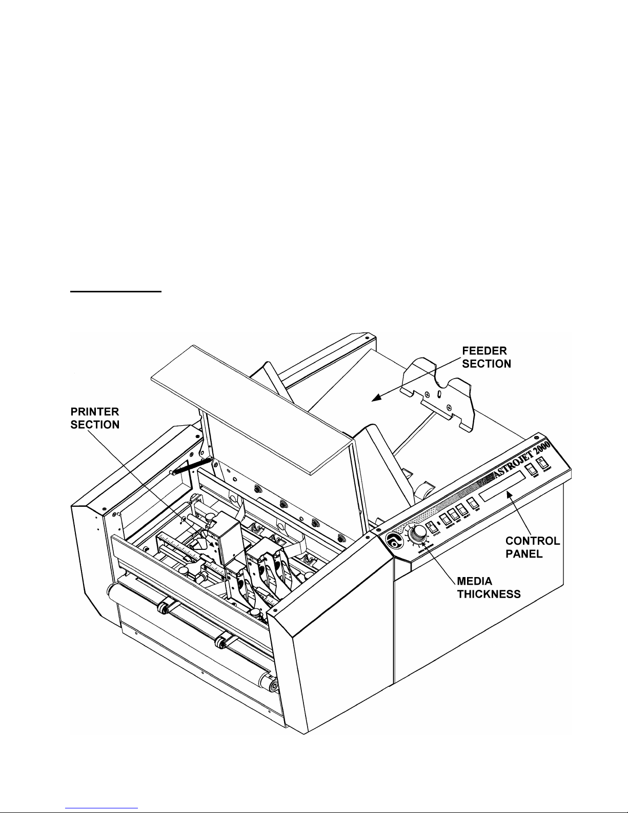
Components
The main areas of the AstroJet 2000 printer are shown in the following drawing. These
areas are described in the paragraphs that follow.
3
Feeder Section
The media to be printed and addressed is loaded into the feeder section of the AstroJet
2000. It is fed into the printer section as required at the speed selected by the operator from
the AstroJet 2000 Software Control Panel. The feeder is adjustable for a wide variety of
media.
Printer Section
The Printer is the most important part of the AstroJet 2000. It is here that the address and
other information are printed on the media. Two important features of the printer that you
should become familiar with are:
• The Control Panel
• The Medial Thickness Adjustment
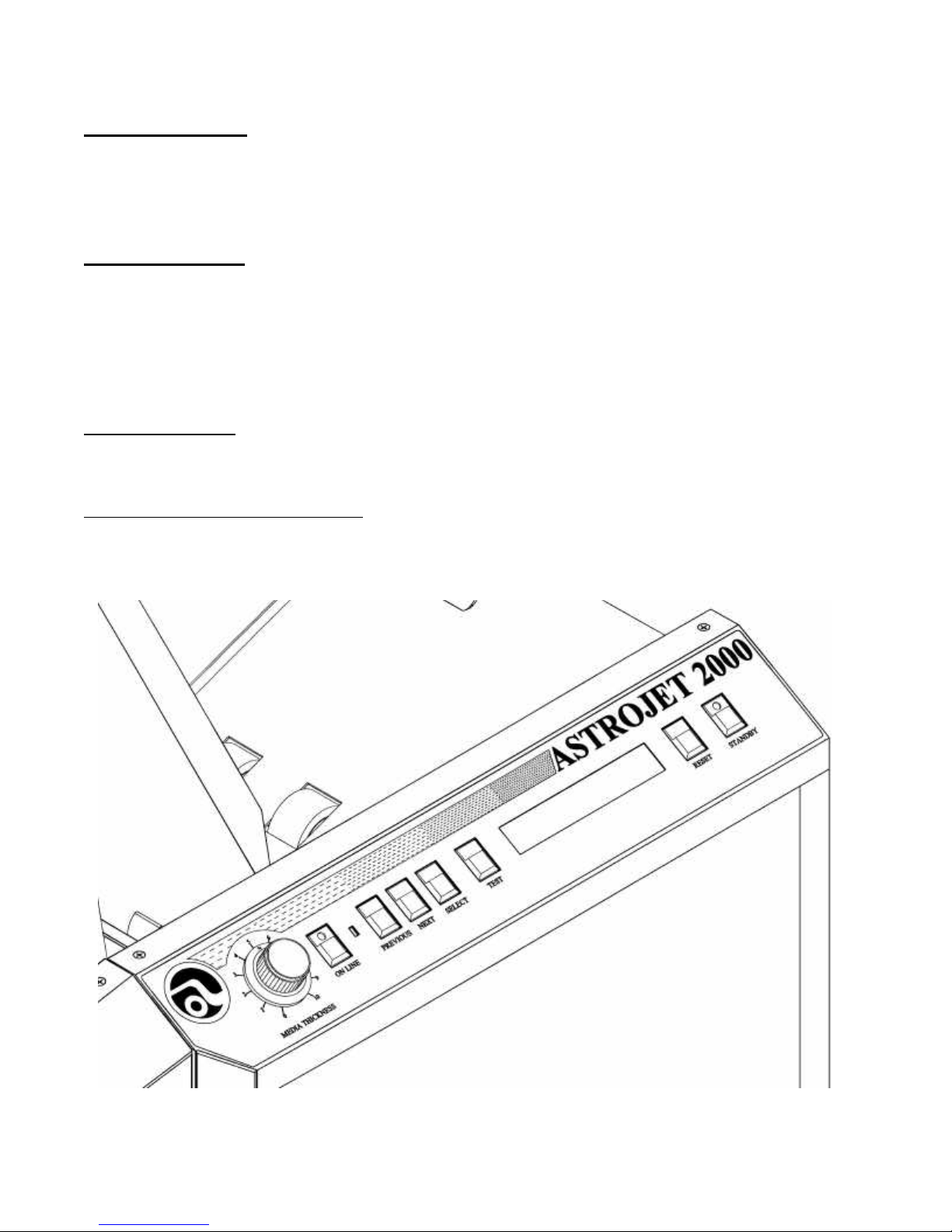
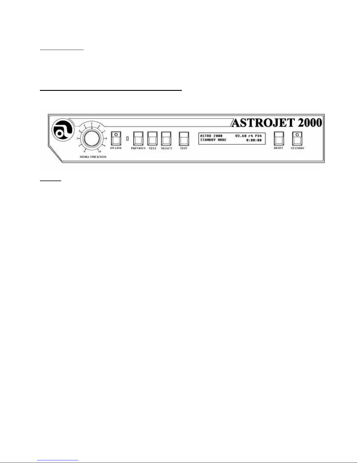
The Control Panel
The control panel is on the front of the printer and contains the controls and indicators
(described in the following table) used to set up and operate the AstroJet 2000.
The Media Thickness Adjustment
The Media Thickness Adjustment is to the left of the ON LINE button on the control panel. It
adjusts for media thickness and is turned counterclockwise for thin media, and clockwise for
thick media.
4
Keypad Definitions
CONTROL / INDICATOR DESCRIPTION
OPERATOR DISPLAY Indicates AstroJet 2000 status including menus
ON LINE When this indicator button is lit, the AstroJet 2000
PREVIOUS When in menu mode, will scroll to the previous
NEXT When in menu mode, will scroll to the previous
SELECT/FEED Locks and unlocks selection when in the menu
and error messages. Any display readout
indicates that the unit is ON.
is ready to accept data from your computer and
begin printing. Turns the printer on and off line.
selection. When in select mode, will scroll
through choices.
selection. When in select mode, will scroll
through choices.
mode. In the operational mode it starts and stops
the feeder.
TEST NON FUNCTIONING.
RESET NON FUNCTIONING.
STANDBY Toggles the printer between the ON LINE and
STANDBY modes.
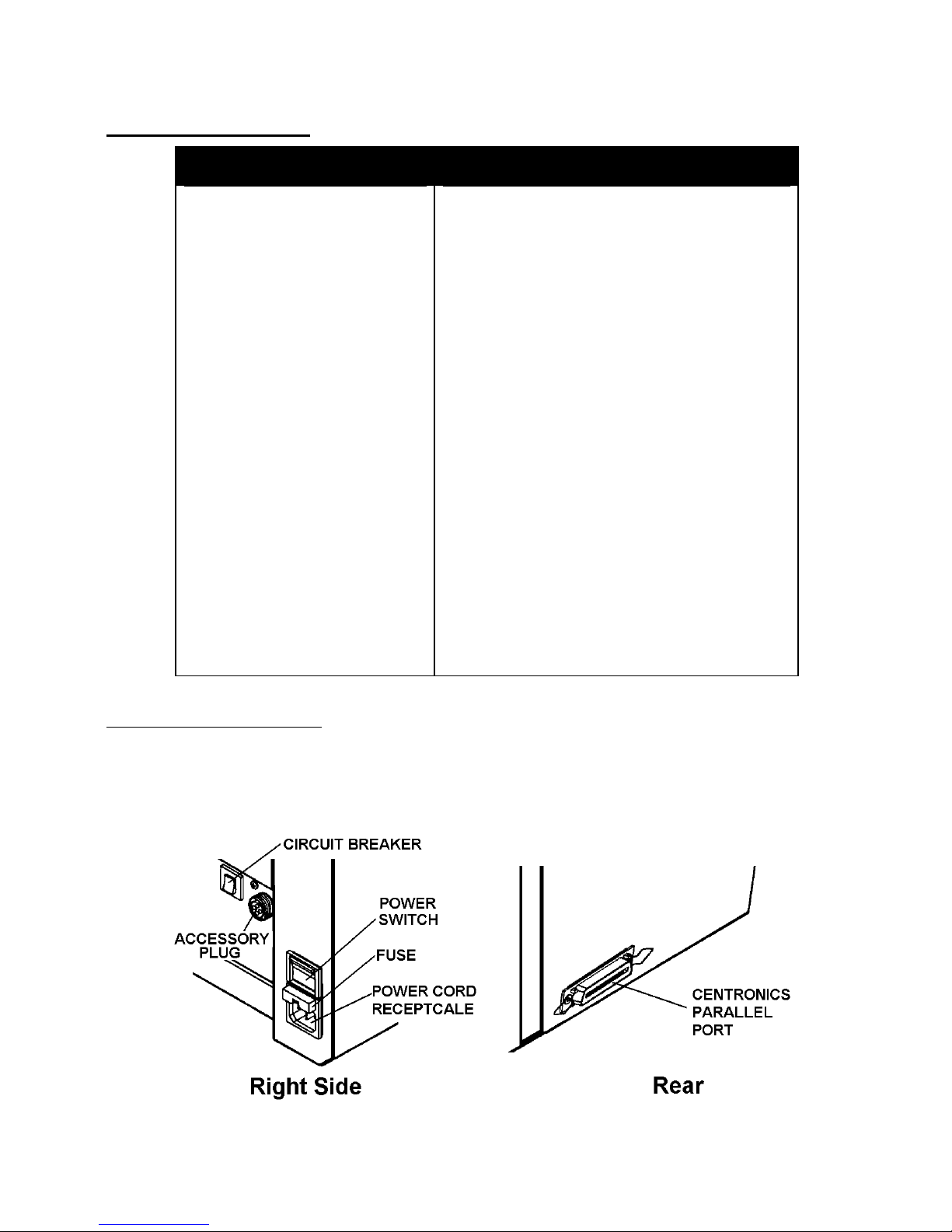
Interface and Power Panel
While facing the control panel of the AstroJet 2000, the power panel can be found on the
right of the machine. It contains the main power switch, fuse, power cord receptacle, circuit
breaker, an d accessory plug. At the rear of the printer you will find the Centronics parallel
port.
5
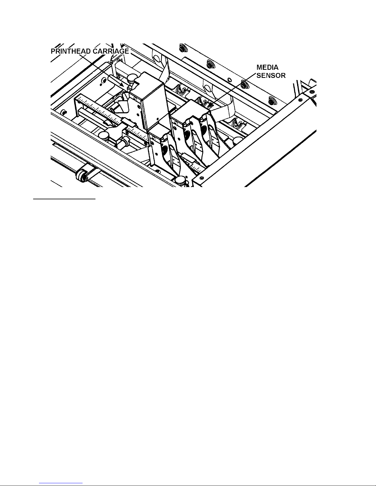
Printhead Carriage
The AstroJet 2000 has five printheads. The heads are arranged in the following
configuration:
Head 1 is on a separate rail and can be positioned between the other two banks of heads.
Heads 2 and 3 are banked together as are heads 4 and 5. These heads share the same
rail assembly.
The AstroJet 2000 Layout software shows the position of the heads and how they are
banked together. For more information on this feature, please check Section 4 Operating
the AstroJet 2000 or the AstroJet 2000 software help program.
You can move the various printing banks from side to side to position the information
properly on the media with the following restrictions:
Head 1 prints a band 1/2” wide and may be positioned anywhere within a range of 9-3/8” on
the media. It can be positioned next to and stitched to Head 2 or Head 4 to form a printing
band 1-1/2” wide. It should not be positioned next to Head 3 or Head 5, as the exit rollers
will cause tracking on the printing from those respective heads.
Heads 2 and 3 and Heads 4 and 5 form a continuous printing bank of 1” each. The
maximum distance that these two banks can be placed apart is 9-3/8”. The minimum
distance they can be placed with respect to each other is 1-3/4”. When the banks are
placed that distance from each other Head 1 can be placed between them. It is
recommended that Head 1 be placed as close to Head 4 under these circumstances if a 11/2” prin ting width is required.
A minimum of a 1/4” margin should be left at the top and bottom of the media to insure good
feeding and print quality. In addition a 1/4” margin should be left at the leading and trailing
edges of the media.
6
Media Sensor
The media sensor is located behind the front feed plate just before the printhead carriage. It
senses the leading edge of the media and communicates this to the software. It is very
important that the media sensor be kept clean.
Operator Display Screen and Menu
When you first turn on the AstroJet 2000, you see the AstroJet 2000 welcome screen, and
the STANDBY key is lit.
MENU
To access the Menu press the STANDBY key to put the printer in the on line mode and then
press the ON LINE key to take the print off line. This action will place the AstroJet 2000 in
the MENU mode and permit access to the following settings and adjustments:
• Left Margin Setting
• Purge
• Counter
• Print Speed
7

Notes
8

Section 3 – Installation and Setup
Before using the AstroJet 2000 Printer for the first time, the following procedures must be
performed:
• Choose a location for the AstroJet 2000 Printer
• Install the inkjet cartridges
• Plug in the AstroJet 2000
• Set up the AstroJet 2000
• Install the AstroJet 2000 software
• Set up the transport
• Adjust for media thickness
• Position the printed output on the media
Choose a Location
Ø The AstroJet 2000 should be attached to the computer with a parallel printer
cable not more than 6 feet in length.
Ø Use a grounded electrical outlet. DO NOT USE AN ADA PTER PLUG!
Ø Do not use outlets that are controlled by wall switches.
Ø Do not use an outlet that shares the same circuit with large electrical machines
or appliances.
Ø Protect the AstroJet 2000 from excessive heat, dust, and moisture – avoid
placing it in direct sunlight.
Install the Inkjet Cartridges
NOTE: For optimum image quality during the run, refer to Cleaning the Printhead on page
34.
HP 51645A Inkjet Cartridges
The AstroJet 2000 can be equipped with 5 inkjet cartridges to give a total printing area of 2
1/2 inches. The cartridges are installed as follows:
• Remove the inkjet cartridge from its packaging, taking care not to touch the
copper contacts, the metal plate, or the gold printhead. Remove the protective
tape from the printhead.
• The cartridges are held in place by vertical brackets mounted on the inkjet
cartridge holder.
• With the cartridge’s gold printhead pointing toward the rear of the unit and while
holding it vertically, slide the bottom edge of the cartridge down along the front of
the bracket until it slides partly into place.
9
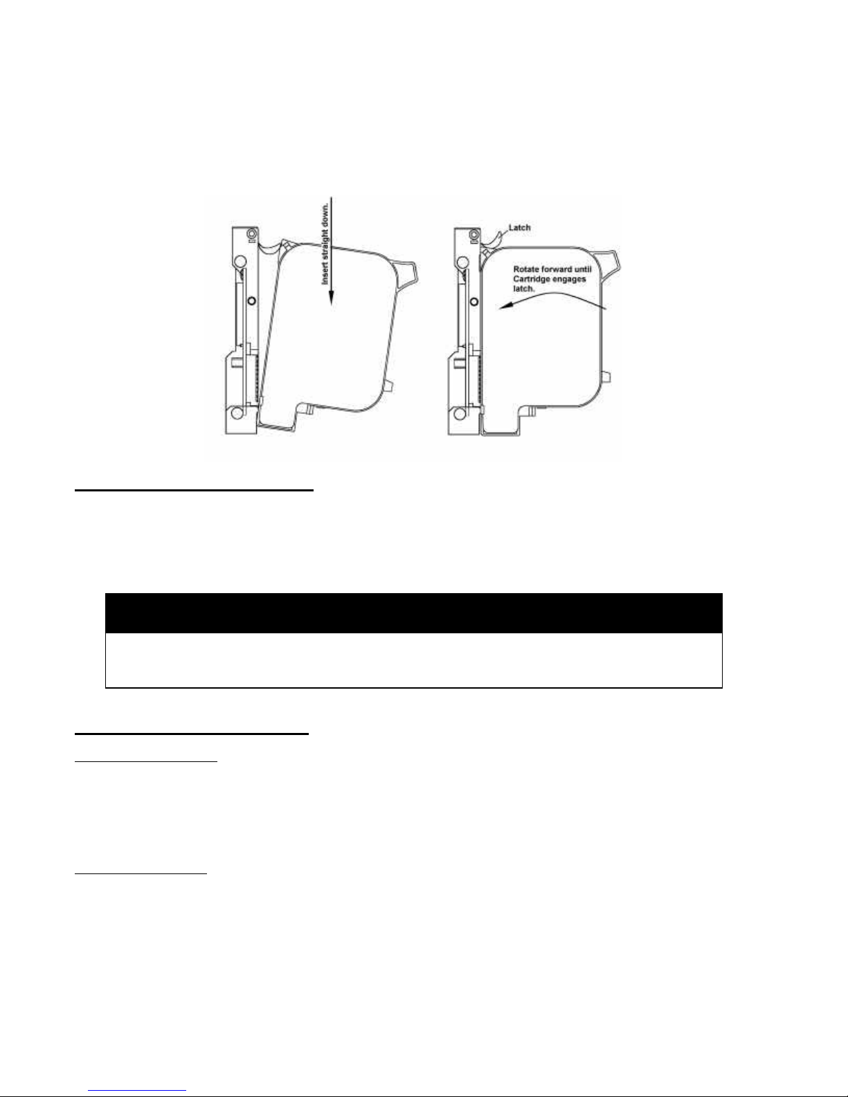
• At this point press the upper part of the cartridge toward the bracket until it clicks
completely into place under the metal spring secured to the bracket. (See the
diagram below.)
• Repeat the above for the remaining cartridges.
Plug in the AstroJet 2000
Make sure that the main power switch of the AstroJet 2000 Printer is in the OFF position.
1. Connect one end of the power cord to the rear of the AstroJet 2000 in the
corresponding receptacle.
2. Plug the other end into a 120-Volt AC, 60 Hz. Grounded outlet.
CAUTION
DO NOT USE AN ADAPTER PLUG OR EXTENSION CORD TO CONNECT
THE ASTROJET 2000 PRINTER TO THE WALL RECEPTACLE!
Set up the AstroJet 2000
Connect the Printer
In order for your computer and the AstroJet 2000 to work toget her, you will need to connect
them with a parallel cable. The cable is connected between the parallel port on the
computer and the printer. The cable used to connect the AstroJet 2000 to the computer
must not exceed 6 feet long.
Set up the Feeder
NOTE: The AstroJet 2000 is supplied with two types of sheet separators. A soft tip which is
installed on the unit when you receive it is for use with standard 20 # paper and a hard tip
for thicker media. Refer to the drawing below for the location of the separator tips. To
change them release the separator-locking lever on the left side of the feeder and lower the
separators. Remove the screw attaching the tip to the separator. Remove the existing
10
separator and install the new one. Take care not to loose the mounting screw in the
machine.
The following steps will assist you in setting the feeder portion of the AstroJet 2000:
1. Place one piece of media on the feeder table move the side guides out to their extreme
open position. Release the separator-locking lever located on the left side of the feeder
and raise the separators to their up and locked position.
2. There are four separators on the feeder. Use the two center separators for narrow
media and the two end separators for wide media. Place the media under the
separators and lower the separators so that they rest on the media.
3. Move the locking lever up to lock the separators in place.
4. Adjust the side guides to the width of the media and set the back guide so that it just
touches the back of the media.
5. Turn the AstroJet 2000 on and then turn the media thickness knob to set the initial print
head height as follows:
Media Thickness Dial Setting
.004” to 1/32” 0 to 2
1/32” to 1/16” 2 to 3
1/16” to 1/8” 3 to 7
1/8” to 1/4” 7 to 10
NOTE: These are initial settings to check the media feed. It may be necessary to adjust
the MEDIA THICKNESS control to optimize the print quality
6. Press the STAND BY switch then press the SELECT/FEED switch, to test feed media.
Install the Software on the Computer
The computer that is supplied with your AstroJet 2000 System is optimized for efficient,
trouble free operation. It is equipped with a network card (10-base T) to enable you to
connect the AstroJet 2000 System to your existing network. Contact your system manager
or deal er for installation
AstroJet 2000 Software Installation
1. Install the CD in the computer. The CD should start automatically. If it does not click on
Start button, then select Run. Type “D:\Setup.exe” (where D is the CD drive) and click
OK.
2. The AstroJet Setup Menu will appear on your screen. It contains five options.
Install Printer Software
Read the Manuals
Browse this CD
Install Adobe Acrobat – This is version 4.0 of Adobe Acrobat for reading and printing
the Operator Manuals.
11

www.astromachine.com – This is a link to our web site if you are connected to the
Internet.
3. Click on “Install Printer Software” and then click on the AstroJet Printer model you wish
to install. Follow the instructions on screen. Use default settings only.
Note: If the message “Setup Can Not Execute the Following Program:
C:\ProgramFiles\Astrojet III\DeReg.exe” or ”The following file is in use and can not be
updated” appears, click on Cancel button and continue with the installation.
4. If this is a new printer installation (not a software update) skip #6. Your software and
firmware are installed and configured.
5. If this is software and firmware update you must download new bios to the printer.
Connect printer to the computer and turn it on. Open AstroJet Control Panel and click on
Advanced… button then Update BIOS button. Follow instructions on screen.
6. Be sure to fill out and mail registration sheet to insure that you will be notified of all
updates to the software and firmware.
12
Section 4 – Operating the AstroJet 2000
Once the AstroJet 2000 software has been installed on the computer and the AstroJet 2000
printer has been supplied with media and ink cartridges, it is ready to print. Using your
existing database, you create a Layout and Job files with the AstroJet 2000 software. The
computer sends the job to the AstroJet 2000 printer. The AstroJet 2000 then prints the Job
with both the addresses and other information you input in the layout.
This section explains how the AstroJet 2000 System is used and is divided into five main
categories:
• Software Tutorial
• Starting Up
• Preparing a Job
• Running a Job
• Printing Tips
Software Tutorial
Description of the Software
The following is a brief tutorial on how to use the AstroJet Printer Software. A more detailed
description of the various parts of the software may be found in the AstroJet “Help” menu
that accompanies the software. It is assumed that you have experience in navigating
through Windows. If you are new to computers or are not familiar with Windows many
books are available that can hel p you.
The software is divided into two parts, The AstroJet Layout Editor and the AstroJet Control
Panel. When the AstroJet Printer Software was loaded on the computer, the two icons
shown below were placed on the desktop.
The AstroJet III folder was placed in your Program Files. This is the place where all of the
AstroJet software resides. The AstroJet Layout Editor, AstroJet Control Panel and Help files
are located in this folder along with the AccuJet Data folder. The AccuJet Data folder
contains several additional folders. These folders contain all of the information required by
the AstroJet Printer Software to create and run the job. The file structure is illustrated below:
13
1 AstroJet III
1 AccuJet Data
0 Bios
0 Databases
0 Fonts
0 Jobs
0 Logos
0 Projects
The latest version of the system Bios is stored here.
This folder is used to store your databases.
When a job is printed from the AstroJet Control Panel
the fonts and logos used for that job are rendered in a
format that the AstroJet Image Bl aster Printer can use.
These rendered fonts and logos are stored in this folder
for future use when the job is run again.
The Jobs folder shows information about the job such as
total number of records, the template used to layout the
job, resolution, and last record processed.
The Logos folder can be used to store any logos in
Windows .BMP format that are used with the job.
This folder stores all of the information necessary for the
software to format and run the job.
The AstroJet Layout Editor is used to create the job. The AstroJet Control Panel is used to
send the job you created to the AstroJet Printer. All jobs are designed in the AstroJet Layout
Editor. This is where we will begin with this tutorial.
Starting the Software
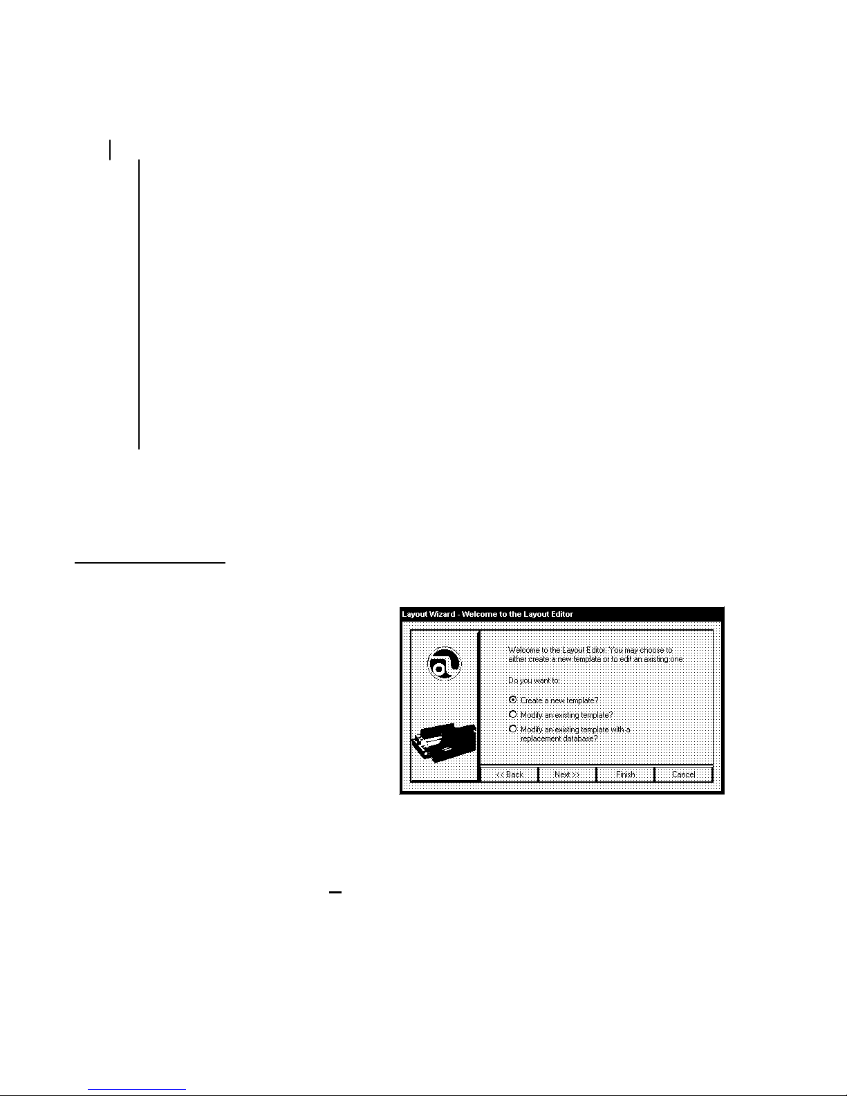
Double click on the AstroJet Layout Editor icon to open the program and we will begin.
The first screen that appears is the
“Welcome to the AstroJet Layout Editor”
screen. There are three choices,
"Create a new template?", "Modify an
existing template?”, and “Modify an
existing template with a replacement
database?”. Click on the “Create a new
template?” and then click on the Next>>
button.
The “Layout Wizard – Select Database”
screen will appear. Click Next>> to
continue. The “Open” window is used to search and select the database. The
11 Databases folder in the AstroJet software is the default. You should store your
databases in this folder. Select the database type from the drop down menu. Next, select
the appropriate database and click Open to open the database. For more information on
databases and how to prepare them for the AstroJet refer to DATABASES at the end of this
section.
14
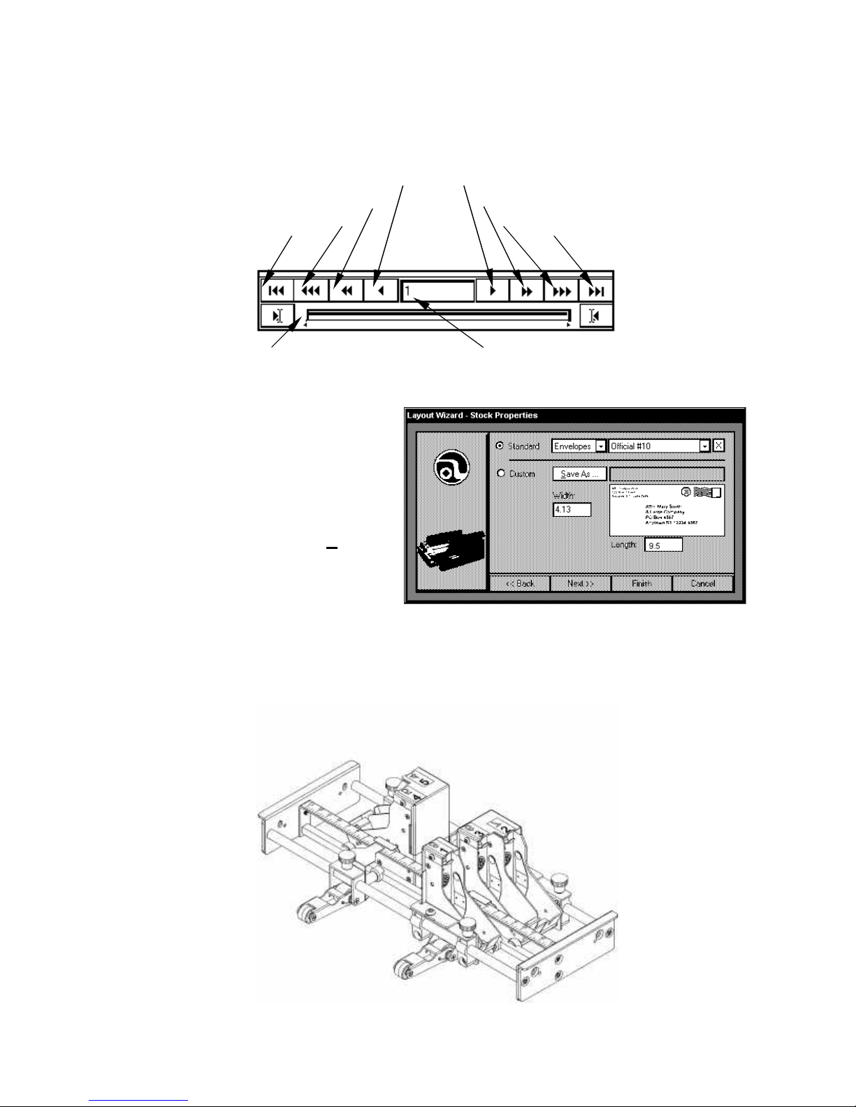
Move 1 Backward Move 1 Forward
Record Position Record Number
The Wizard will switch to the “Database View – (file name)”. The first record of the
database will be displayed. There is a series of arrows just below the record. These can be
used to step through the records as follows:
Move 10 Backward Move 10 Forward
Move 10X Backward Move 10X Forward
Move to First Record Move to Last Record
Click Next>> and the “Layout Wizard – Stock Properties” window will open. Select the size
and/or type of stock that y ou will be
printing on. There are many standard
envelopes available. Select one by
using the drop down menu next to
Standard or select Custom and enter
the Width and Length of the piece.
You may save the custom size by
giving it a name and clicking on Save
As…. When you have completed this
step, click Finish. The “Layout Editor
– Untitled” screen will appear.
When the software was installed on the computer, the printing banks were set up according
to the AstroJet 2000’s configuration. The white lines in the display represent the print
cartridges and how they are positioned in the printer. The AstroJet 2000 has five print
cartridges. The print cartridges are arranged on two sets of rails as follows:
15

Printhead 1 may be connected in the software to either to head 4 or head 2. This will permit
you to print up to 1.5 inch wide on the media. There are some restrictions as to the
placement of printhead 1, however due to the guide rollers in the printing section. If in doubt
run a test before beginning the job.
Before continuing, spend a little time exploring the “Layout Editor – Untitled” screen.
The AstroJet 2000 uses five
print heads. To eliminate the
unused heads, click on Setup,
then Print head. Click on the
boxes in the window for the
head positions that are not
used (heads 6, 7, and 8) and
de-select them. Then click OK.
The bands in the layout that
are remaining represent the
print heads on your particular
model of AstroJet Printer and
are properly banked together.
In the top line of the display, you see the following items:
File View Fields Setup Tools Help
16

Each of these controls a drop down menu that permit choices that perform the tasks
required to set up the job. The second line contains icons that represent those tasks. The
drop down menus duplicates the function of some of the icons. It really depends on how
you wish to use the software. For the purpose of this tutorial, we will use the icon buttons to
set up a sample job.
Setting up the Job
When you first opened the job you set the size of the piece. The piece size may be
changed at any time during or after the setup of the job by clicking on Setup and then
Envelope Size or by clicking on the Envelope Size icon on the menu bar.
Click on this icon and the Envelope Properties window will open. Select either
Standard or Custom. Press the OK button. If you choose Custom you may use any
number or fraction from 3 inches up to 15 inches in width and from 5 inches up to 17 inches
in length. When you press the OK button, the Layout screen will adjust the view of the
media to the size selected automatically. If you intend to use the Custom size again, save it
by giving it a name and clicking on Save As next to Custom. You must enter a name for
this feature to work.
Refer to the screen image on page 18. The corresponding print banks will show on the
screen in white. These banks can be moved together or separately in sets in the same way
that they can be changed on the printer. The maximum printing area on the Image Blaster
with 6 heads is 3 inches.
To the right of the template image are numbers. These correspond to the printheads and
are marked with the same numbers on the AstroJet Printer. Also, to the right is a line. This
guideline can be moved to any point on the layout to assist you in lining up the fields or
information that you will be adding. To get all of the information to line up on a particular
bank move the line close to the position desired for the lines and right click on the mouse
while the guideline is selected with the mouse pointer.
The next step is to build the job on the layout. When you click on the “Text Field
Properties” icon the “Layout Editor – Text Field Properties” window will open. This window
permits you to enable up to 24 lines of information and data with up to 4000 characters per
Text Field. Enable one button for each
line of type style in the layout. If you wish
to make additions, deletions, changes in
the style of type, or the number of lines,
you can click on this icon anytime during
the setup or before you run the job to
make changes. For the purposes of this
tutorial, we are going to enable the first 4
lines and set them up according to the
picture. Line 1 will be for the database
address. Line 2 will be for the company
name in the return address. Line 3 will be
for the rest of the return address. Line 4
will be for an additional message on the media.
17

After enabling the lines, select the style of font, size of type, and whether the type should be
bold, italicized, underlined or struck through . The down
arrow will permit you to access the other sixteen lines of
data that are available for use. Click OK to continue.
The software returns to the Layout Editor screen and the
data selected will be displayed at the bottom right hand
corner of the media layout called the blotter area. Use the
mouse to move each line into the general area of the
layout where they will be finally positioned. Once you
have done this, place the cursor on the field that will
contain the variable address from y our database and
double click on the left mouse button.
The following window will appear on the screen. This window allows you to layout the
variable address fields in their proper order.
Use the drop down box in the upper right hand corner of the window to add fields from your
database in their appropriate position in the layout. Click on the icon to eliminate blank
lines in the database. The icon will disable all the information in the layout. The
icon selects the standard barcode font and displays the information using a fixed default
font. The database may be setup in any format that conforms to a standard address.
Database fields may be combined on a particular line and punctuation and spaces may be
added. When finished click OK.
NOTE: The database Field may be edited at any time by double clicking on it.
To add a fixed return address to the media double click on the first line in the return
address. The following window will appear. Type the information as shown in that window.
Each line that uses a different type or style of type is entered by means of an Text Filed
Editor window. When you have completed the entry below click OK.
18

The next step is to enter the rest of the return address. Double click on the second line in
the return address area in the layout and enter the following in the “Text Field Editor – Field
3” window:
Once you click the OK button, the second line will appear as you typed it in the “Layout
Editor” window. To the right of the media
layout is a vertical lin e, you can drag this line
to the position where you want the
information from the two edits to line up and
then right click on the line. The lines will
then line up with each other.
The AstroJet Software has the flexibility to
allow you to add additional information to your layout in any position on it. For the purpose
of this tutorial, we will add the following line at the bottom of the layout:
19

You may add as many messages to the layout in any position on the media by simply
enabling an Address Line in the “Text Field
Properties” window and dragging the line
from the blotter area to the position you
would like to have it appear on the media.
Then double click on the line and enter the
information in the “Text Field Editor” window.
The Logo icon is used to add logos and graphics in .BMP format to your design.
When you click on the “Logo” icon or access it from the Fields drop box, under Logos, the
“Layout Editor-Logo Properties” window appears. You may add up to eight logos to the
layout. Each logo is selected by first
activating one of the Logo Enable
buttons and then typing in the file name
and location. You can also click on the
folder icon and browse for the desired
file. The default is the logo folder
located in the AstroJet software. Use
this folder to store logos.
The AstroJet is a 600-dpi printer. When
creating graphics or logos for use on the
AstroJet, 1” is equal to 600 pixels. A
logo or graphics that is 300 pixels tall will
print the width of a single print head or 1/2” high. If you wish to print a logo or graphic that
would span two or more banked printheads it
has to be taller than 300 pixels.
Once you have found the logo you wish to use,
click OK. The screen will return to the Layout
Editor and the logo will appear in the lower right
hand corner to the right of the media layout in
the blotter area. Use your mouse to place the
20

logo or graphic on the layout as illustrated. The logo can be edited with Windows paint by
double clicking on it.
Press this button to add the USPS bar code to the address. Press the number 1
Enable button and then select the Field where the bar code is located in the database.
Then press OK. The bar code
will appear in the lower right
hand corner of your screen just
below the layout in the blotter
area. Click and drag the bar
code to its position under the
address as shown.
IMPORTANT NOTE: The bar
code displayed in the Layout
Editor view is a representation of
the positioning of the bar code
on your layout. If you use the data base view
function in the Layout Editor, the bar code will
appear the same for each record. When the
record is printed on the AstroJet Printer the bar
code will be the correct one for each zip code in
the database.
You may also add a barcode with the “Layout
Editor”. This is used when the barcode
appears as a five plus four in one data field and a separate two-digit delivery point in
another field. Click on the Text Field Properties icon and Enable a font. Click OK. Drag
the field to a position under or over the address and double click on it. When the “Text Field
Editor” window opens, click on the barcode icon to select the “Astro USPS” font. Then
select the fields that contain the barcode information from the drop down box and combine
them on the same line without any spaces. Click OK and position the resulting image on
the layout.
The image will appear as follows: | ~FIELD_4~ | | ~FIELD_5~ | When in database view the
actual barcode for each address will display.
The actual database records can be viewed by clicking on the Template/Database View
icon. A set of arrow buttons will appear below the icons that will permit you to step through
the records or search for specific records..
Saving the Template
Now that you have designed the template using the layout editor, it is time to save it.
Click on File and select either Save Template or Save Template As… and the “Save As”
window will appear. You must give the template file a unique name with the extension
“.AJPJT” then click Save. The Template will be saved in the AstroJet Data 1Projects
folder.
21

Saving the Job
IMPORTANT: Before exiting the “Layout Editor” you must create a job so that the data
base and the layout can be
output on your printer. To
do this select, File and
then select New Job. The
“Layout Wizard – Select
Print Range” window will
appear. Click Next>> to
select “Database View –
(database name)“. At this
point, it is possible to
select a specific range of
records to be output. To
set the range select the
starting record that you
wish to use by using the database advance buttons. Click on the left (44 É) to choose the
starting record. Use the same buttons to step to the last record you wish to print and click
on the right button (É33 ) to set the end of the job.
Selection of specific records to print can be done anytime by following this procedure.
Always save the job to make the range changes permanent.
If you wish to print all of the database records then skip this step and click on Next>>. The
“Save As” window will appear. The default is the layout file name is displayed. Click save
to save it or enter a unique name for the job with the “.AJJOB” extension and click Save.
The template and the job that have been created are now ready to be printed. Close the
layout window by clicking File and then Exit.
Running the Job
Before running the job make sure that the AstroJet Printer is turned on and properly
connected to the computer.
There are two ways that a job can be selected to be run. One is from the AstroJet Control
Panel button in the “Layout Editor”. The other is from the “AstroJet Control Panel”
icon on the desktop of the computer.
For the purpose of this tutorial, double click on the “AstroJet Control Panel” icon on the
desktop. The following window will appear:
22

By clicking on the Open Folder 1 icon, the Load Job window will open. Choose the job you
just created and then click Load Job.
The database information will now display in the Control Panel. The arrows below the
database information can be used to step through the data. In addition, a Search ,
Search next , and Jump buttons are available to help you find a specific record
23

in the database. Simply click on the search or jump button and fill in the requested
information. The following is a list and description of each search variable:
Variable Default Description
Search For Must be filled
in.
Case Sensitive 0 Specifies whether upper and lower case characters should be
Search direction All 0 Specifies a search the entire database. Non-zero value forces
Search Direction
Forward
Look In (All Fields) Specifies the field the search will look in to. The value string
Limit search to: 0 Specifies the maximum number of records to search. “0” is
0 Specifies the direction of the search, either forward or
This field specifies the criteria the search must find. It can be
a complete or partial, word or phrase. If it is Case Sensitive ,
check the box in the Options and make sure that the Search
For is precise. If the criteria are in a specific field in the
database it can be specified in the Look In box.
treated as identical in searches. Non-zero value specifies
searches are sensitive to the case of letters. 0 calls for case
insensitive searches.
searches of the entire database in the forward direction,
proceeding from the first record to the last. A “0” value in the
Limit causes a directional search from the current position
base on Search Forward, and Search Limit.
backward. A number in Limit specifies forward searches, “0”
specifies backward. Not used when Search All is set to a nonzero value.
must be a valid field name for the database in use, or (All
Fields). If the Look In value doesn’t match a valid field name
(All Fields) is used instead.
implied to mean the number of records from the current
position to the end of the database in the specified direction.
Not used Search All is set to a non-zero value.
Template “ ” The last search template specified. This is the default pattern
to be searched for.
NOTE: The icon is used to search for the next record. The arrow in the icon shows
the direction that the search is moving through the database. When the last record is found
that meets the criteria in the search the “Control Panel – Search” window will reappear.
24

1 2 3 4 5 6 7 8 9 10 11 12
A description of the Control Panel controls follows:
13 14 15 16 17 18 19 20
1. Name of the Job file. 11. This button will print one piece for setup.
2. Current database record. 12. This button will open the Layout Editor.
3. These buttons and the ones to the right are
used to step through the database.
4. Search is used to find a record that contains
specific information.
5. Continue searching for the same specific
information.
6. Jump to a specific record by number. 16. The total number of records in the current
7. The 11 is used to open the job file to be used. 17. The status of the printer is displayed here.
8. The üü verifies the integrity of the database. 18. This is the number of the first record in the
9. STOP will pause the printing process 19. This is the number of the last record in the
10. GO is used to start printing the job 20. These buttons control the resolution of the
13. This area shows the status of the download
process.
14. The number of the current record is displayed
here.
15. The number of records in the printer buffer is
displayed here.
database is displayed here.
database selected for printing.
database selected for printing.
printed image.
25

NOTE: When the job is running the display in the lower right hand corner of the Control
Panel will tell you the speed of the printer in Inches Per Second (ips) and the approximate
number of pieces being processed per hour. This only displays when the Printer is
connected and printing pieces.
Bundle and Bag Breaks
A Bundle and a Bag Break feature are available in the AstroJet Control Panel Software.
This feature will permit you to stop the AstroJet printer in order to separate the pieces
according to USPS regulations. The various mail management software available for
presorting have the ability to prepare your database to conform to Post Office regulations.
We will not go into this part of the presorting, but we do suggest that you become familiar
with the software you are using to presort your database. The USPS provides a wealth of
information on their presorting regulations. Some of these are:
1. “Domestic Mail Manual” (DMM), published by the USPS and available by
subscription by calling (202) 783-3238.
2. “Postal Bulletin” which provides corrections and additions to the DMM on a
regular basis. You can subscribe to this by calling (202) 512-1800.
3. There are also several informative, free booklets available from your local Post
Office and the USPS on the subject of preparation of presorted mail.
4. Much useful information can also be obtained from the USPS web site at
www.usps.com.
The bundle and bag break windows can be found under the Advanced… button on the
Control Panel. When you click on this button the “Control Panel – Advanced Settings”
window will appear. At the bottom of the window there are two buttons, Bag Break and
Bundle Break. The functions of these buttons are similar. They are provided to permit you
to separate bags of mail and bundles in the same job. You can use either or both of these
to separate the pieces.
To use this feature you must first put a non -alpha or numeric character in your database,
either in one of the existing fields or create a field for the character. You may use any
character except the tilde (~). All presorting software is capable of preparing your database
in this way. For example we used (*) for bag break and (##) for bundle break.
26

Once you have loaded your job in the control panel, select Advanced…, then select Bag
Break, the above window will appear. You can enable these functions by clicking on the
Enable Breaks to select it.
Select the field where the break character was placed in the database. If you used a
character other than the (*) place that in the Break Sequence block, then select pieces for
the break in the Break Delay block. The printer will stop at the break. Then click OK.
If you require a Bundle Break repeat the above sequence, but use a different character or
field to designate this function. Remember you can not use any alpha or numeric character
or the tilde (~) for this function.
Start the printing process by clicking the GO button. When the AstroJet Control Panel
software reaches a break character the printer will stop feeding. To restart the printing
process press SELECT on the control panel.
Running a Job
Setting up the Feeder
The following steps will assist you in setting the feeder portion of the AstroJet 2000:
1. Place one piece of media on the feeder table. Move the side guides out to their extreme
open position. Release the separator-locking lever located on the left side of the feeder
and raise the separators to their up and locked position.
2. There are four separators on the feeder. Use the two center separators for narrow
media and the two end separators for wide media. Place the media under the
separators and lower the separators so that they rest on the media.
NOTE: Two types of separator tips are packaged with the AstroJet 2000. The set that is
installed on the unit was designed for all types of media from single sheets of paper to
booklets and carries the part number 90-103-09S. The second set is made from a
harder material and can be used for all media except single sheets of paper. It has a
part number of 90-103-09,
3. Move the locking lever up to lock the separators.
4. Adjust the side guides to the width of the media and set the back guide so that it just
touches the back of the media.
5. Turn the AstroJet 2000 on and then turn the medial thickness knob to set the initial print
head height as follows:
Media Thickness Dial Setting
.004” to 1/32” 0 to 2
1/32” to 1/16” 2 to 3
1/16” to 1/8” 3 to 7
1/8” to 1/4” 7 to 10
Starting Up the AstroJet 2000
It is a good idea to Purge the printheads before beginning to run a job. This can be done
from the AstroJet 2000 LCD Display Panel. Press STANDBY, then ON LINE to put the
AstroJet 2000 in the menu mode. Then using the NEXT or PREVIOUS buttons scroll to
27

PURGE: then press the SELECT button. Allow the AstroJet 2000 to run a few pieces then
press SELECT again to stop the purge. Check that the pattern run on the media is even,
without any blank areas or white streaks. If the pattern is OK, then return the AstroJet to the
standby mode by pressing the STANDBY button. Anytime the AstroJet 2000 sits idle for a
while the purge routine should be run before running the job.
Printing the Job
Click on the GO button to begin the job. The AstroJet 2000 will begin by rendering the fonts
and logos and storing them in the Fonts folder. Depending on the complexity of the page
this process takes only a few minutes. Once a font or logo is rendered, the AstroJet 2000
can call it up from this folder for reuse the next time a job that uses that particular type or
type style is run.
Monitoring the Job
The AstroJet 2000 can be stopped by pressing the SELECT/PRINT key or by clicking on
STOP in the Control Panel software without affecting the job. The printer will resume
printing at exactly the same point when it is back on -line.
NOTE: THE ASTROJET 2000 MUST BE OFF-LINE FOR THE FOLLOWING SETTINGS
TO BE CHANGED.
Checking the Piece Counter
To check the number of pieces run proceed as follows:
1. Turn the printer off-line.
2. Use the PREVIOUS or NEXT key to bring COUNTERS to the top line.
3. Press the SELECT key, the asterisk will disappear and MACH CYCLES with a number
will appear.
4. To reset this to “0” turn the machine off and then on.
5. To continue press the SELECT the asterisks will reappear.
Setting Print Resolution
To set or change the Print Speed:
1. Turn the Printer off-line.
2. Use the PREVIOUS or NEXT button to bring PRINT SPEED to the top line in the display.
3. Press the SELECT key, the asterisk will disappear.
4. Use the PREVIOUS or NEXT key to select the desired speed LOW, MEDIUM, or HIGH.
NOTE: If Standard resolution is selected there will be two speed choices available STD and
HIGH. If Draft resolution is selected three speed choices will be available: LOW, STD, and
HIGH. In the HIGH-resolution mode only the LOW speed is available.
5. Press the SELECT key to lock in the selection. The asterisk will reappear.
28

Purge the Printheads
It is necessary to Purge the printheads, especially when the AstroJet 2000 has been idle for
a period of time:
1. Turn the printer off-line.
2. Load media into the feeder on the AstroJet 2000.
3. Use the PREVIOUS or NEXT key to bring PURGE to the top line of the display.
4. Press the SELECT key. The asterisk will disappear and the AstroJet 2000 will start to
feed media and purge the print heads.
5. Press SELECT again to stop the purge and return the AstroJet 2000 to STAND BY.
6. Check that there is a consistent pattern printed on the media. If not, repeat Step 4 and 5
until the pattern is consistent.
Setting Left Margin
To increase the gap at the lead edge of the piece:
1. Turn the printer off-line.
2. Use the PREVIOUS or NEXT key to bring LEFT MARGIN to the top line.
3. Press the SELECT key. The asterisk will disappear.
4. Use the PREVIOUS or NEXT key to select the desired left margin in 0.1-inch
increments.
5. Press the SELECT key to lock in the selection. The asterisk will reappear.
Printing Tips
Types of Media
The AstroJet 2000 will print on many types of mailing media, but some restrictions apply.
As with any other printing process, the texture of the media has a direct effect on both the
print quality and the ink drying time. It is best to test each new type of media to determine
performance level s before beginning the Job.
Since coated and plastic types of paper do not easily absorb ink, smearing may occur. Print
may appear fuzzy on very porous paper. Another cause of fuzzy printouts is excessive
buildup of dust within the machine, or a printhead is too far away from the media. Be aware,
that when printing in the High Quality mode, drying time for the ink is longer than in the
other modes. In addition, when humidity is high, drying time is increased.
Media Thickness
The AstroJet 2000 will handl e pieces up to 1/4” thick (0.250”). All folds must be crisp and
even.
29

CAUTION
DO NOT use stapled pieces in the AstroJet 2000.
DO NOT use paper- clipped pieces in the AstroJet 2000.
These methods of binding the mail piece will damage the printheads, affect print
quality, and may seriously damage your printer. The Astro Warranty Policy will
not cover components damaged through improper use.
The USPS does not accept this type of mail for its automated equipment.
Databases
The AstroJet 2000 System is capable of handling many types of databases. There are,
however, some limitations. To avoid problems we offer the following suggestions to help
you improve the operation of your AstroJet 2000 System.
Large ODBC Databases
Random accessed ODBC databases are not indexed on the first column. As a result the
performance of the printer may get slower and even stop when using very large databases.
To prevent this from occurring, the following actions can be taken before the database is
loaded into the AstroJet 2000 software:
1. The user can convert the ODBC database to a text database (*.CSV file) with the
Layout Editor, and then subsequently open the project with that alternate database.
The Layout Editor explicitly indexes text databases, so performance is not an issue
for these files. Note: the Layout Editor retains ODBC field names in the first record of
the *.CSV file, so when you select it later, you should check off that the “first record
contains field names”.
2. The ODBC database vendor should be encouraged to index their database (on the
first column ascending). The index may be packaged as part of the database file, or
as a separate index file – depending on the format of the database.
3. The users can index the database themselves. To do this, you will need a database
management program for the database type you have. For example to index an
Access database (*.mdb files) require Microsoft Access, and to index dbase III, IV
and V (*.dbf) use Microsoft FoxPro.
4. Use sufficiently small ODBC databases that this effect doesn’t affect printing.
If the database has been saved in the ODBC format there are additional safeguards that
have been added to the layout Editor and Control Panel to warn you and offer a means of
changing the database and improving the performance of the system. The following
solutions have been programmed into the AstroJet 2000 software:
1. The Layout Wizard generates a warning when an ODBC database has been
selected. There is no way for the Layout Editor to determine if the database is
30

indexed, so the user is warned of the potential consequences of selecting an ODBC
database.
2. The ODBC to CSV converter was added to the Layout Editor, so users have a viable
alternative to using ODBC databases directly.
3. A timer has been placed in the Control Panel that mon itors ODBC reads. When
reading of a record exceeds a threshold, the Control Panel stops the job with a
timeout error.
Converting ODBC Databases to *.CSV (Comma Separated Value Format)
To convert an ODBC database to a Comma Separated Value file, use the fol lowing
procedure:
1. Create a new project, or open an existing project in the Layout Editor that uses the
ODBC database you wish to convert. For purposes of this discussion, the example
will be “MY SAMPLE.DBF”.
2. From the “File” menu select “Convert Database”.
3. A wizard is started which tells you the conversion is about to occur, and that it may
take awhile. It also tells you the converted database will be stored in your databases
folder, under the current name with .CSV tacked on the end. In example the output
would be “MY SAMPLE.DBF.CSV”.
4. Press “Next” to start the conversion, or “Cancel” to quit. If you start the conversion,
you will not be able to interrupt it – the process will continue until the conversion is
complete.
5. Exit and restart the Layout Editor. From the Startup Wizard select “Modify an existing
project with a replacement database”. Work through the wizard and select the
converted database, in this case “MY SAMPLE.DBF.CSV”.
6. You can ignore the warning about database structure, because in this case the
structure will be identical.
7. The wizard will ask about # of fields per record – leave it at 0, is the “First record is
used to record field names” – check this box, and delimiter information – leave the
defaults. Press “Next” or “Finish”.
Your project is now associated with the converted database. Access to any record in the
database should be almost instantaneous and the Control Panel should always provide
individual page information faster than the printer can supply stock.
Indexing a Microsoft Access *.MDB file
To index an Access database file for use with the Layout Editor and Control Panel you will
need Microsoft Access ’97 (or 2000). This should be installed on the target system to ensure
the same leave of ODBC is available to Access and the Layout Editor and Control Panel.
Then follow this procedure:
1. Start ACCESS and open the database file, (for example: “MY SAMPLE.MDB”.
2. Select the table to be used - here it is “MY SAMPLE”.
31

3. Click the “Design” button. A window displaying the characteristics of each field
(column) in the database is drawn.
4. Select the first row by clicking in the blank gray square to its left. This selects the
characteristics of first column.
5. At the bottom left click in the cell to the right of the heading “Allow Zero Length” to
display a drop down arrow, from which you will select “yes”.
6. Click the cell to the right of the heading “Indexed” to display a drop down arrow, from
which you select “Yes (Duplicates OK)”
7. Exit Access.
Indexing a dBase III, IV, V, FoxPro (*.DBF) File
To index a dBase file for use with the Layout Editor and Control Panel you will need
Microsoft FoxPro. This should be installed on the target system to ensure the same leave of
ODBC is available to Access and the Layout Editor and Control Panel. Then follow this
procedure:
1. Start FoxPro and open the database file, (for example: “SAMPLE.DBF”.
2. Select the table to be used - here it is “SAMPLE”.
3. If you are asked about the character set to use, select 1252 – Windows ANSI.
4. From the “View” menu select “Table Designer”. A tabbed dialog wills popup.
5. Select the “Fields” tab. Note the name of the first field. Select the Indexes tab.
6. In the cell under Name, type the name for your index. In this case “SAMPLE”.
7. Once this is entered other fields become available. Fill in the following fields:
A. Order – click to show an up arrow (ascending)
B. Type – select regular
C. Expression – enter the field name you noted above
D. Filter – leave blank
8. Click “Okay” and “Yes” to make structures permanent.
9. Exit FoxPro.
32

Section 5 – Maintenance
This section show s you how to care for and replace inkjet cartridges, clear paper jams, and
perform routine operator maintenance to the AstroJet 2000 Printer. Other problems such as
not printing, poor print quality, etc., are also covered. Special tips and suggestions to help
you increase efficiency and avoid problems are also included.
The Inkjet Cartridge
The AstroJet 2000 inkjet cartridges must be replaced when out of ink, when print quality is
poor, or when purging and cleaning have not helped the image quality.
The Approximate life of the HP 51645A Inkjet cartridges based on three lines of 20
characters at 10-point size per address is:
High Quality 50,000 addresses
Standard Quality 100,000 addresses
Draft Quality 200,000 addresses
NOTE: These figures can vary depending on the font selected.
To Replace the HP 51645A Inkjet Cartridge:
1. Remove the cartridge by pulling the top toward you until the cartridge is free from
the retaining latch. Lift the cartridge up and out of the holder.
2. Remove a new print cartridge from its packaging, taking care not to touch the
copper contacts, the metal plate, or the gold printhead. Remove the protective
tape from the printhead.
3. With the gold printhead pointing toward the rear of the unit, slide the bottom edge
of the cartridge down along the front of the bracket until it slides partly into place.
4. Press the upper part of the cartridge toward the bracket until it clicks into place
under the retaining clip of the bracket.
5. Repeat this procedure for each cartridge.
CAUTION
Never shake, drop, or hit the cartridge against the palm of your hand or any
other hard surface. Shaking the print cartridge does not “mix” the ink and
hitting the cartridge against a hard surface does not clear the nozzles Both of
these actions actually hurt the print quality because they allow bubbles to
form near the ink firing chambers. These bubbles prevent the nozzles from
firing causing white streaks in the print image.
Storage
Short-term storage is defined as less than 2 days or less than 1 day in a hot and dry
environment. Long-term storage is defined as more than 2 days or more than 1 day in a hot
and dry environment.
33

Short-term Storage
Long-term Storage
Disposal
Leave the cartridge in the AstroJet 2000 for short periods of time, 2 days or
less.
The next time that the AstroJet 2000 is used, the printhead may have to be
cleaned per the cleaning instructions, below.
HP 51645A
Keep the printhead in an area that is relatively free of dust and paper particles
that is not too dry
Place the cartridges in a Tupperware container with a damp sponge or towel
to maintain humidity and prevent the printhead from drying out.
When the cartridges are ready to be used again, the printhead will need to be
cleaned.
The cartridge may be disposed of in normal manner.
If there should be an ink spill, use soap and water to clean up any problem
areas. Abrasive soap also works well to get the ink off of hands.
Cleaning the Printhead
In order to achieve good print output; maintenance of the printhead is required. Paper fibers
and dust can build up on the printhead degrading the print quality. Proper printhead
maintenance will allow the cartridge to produce good print quality its whole life. A cotton
Tex Wipe® and distilled water is one of the best ways to wipe ink and other build-up off of
the printhead. A Tex Wipe® is 100% cotton, high -density cloth with no chemical additives.
Something comparable is adequate to wipe the nozzles. A good choice of wipe would have
the following qualities:
Soft
Fiberless
No chemical additives
Moist with distilled water
A cloth should NOT be:
Abrasive
Dry
Made of small fibers that can be left behind on the cartridge’s nozzle plate
Never use the following to wipe the printhead:
Industrial paper towels – these cloths usually contain a high recycle content and are
abrasive
34

Toilet paper – this is usually not fiberless
Sponge – particles from the sponge can be left behind on the nozzle plate
The cloth must be soft so that it does not scratch the printhead. It should be fiberless
because small fibers on the cloth can be left behind and block the nozzles of the cartridge.
The cloth must be moist or it will scratch the printhead. Scratches on the printhead prevent
the ink from coming out of the nozzle straight. If the ink drops do not come out of the
nozzles straight they will not land on the paper in the proper place causing fuzzy text.
Distilled water is better than tap water because tap water contains an unmonitored amount
of minerals. During wiping, the water cleans out the nozzles and the fir ing chambers. A
small amount of water mixes with the ink in the chambers. Over time, the minerals in tap
water can leave behind deposits in the chambers that block it completely. A blocked
chamber will show up as a white streak in text or graphics.
The direction and force of the wipe is also important to note. During wiping, harmful
particles on the top of the printhead can be wiped into the nozzles if you are not careful.
The cartridges need to be wiped in a certain way to obtain optimal print quality .
It is important to wipe the cartridge nozzles in the direction of the nozzle rows for optimum
print quality. See below:
Purging the Nozzles
If the printhead sits inactive for a period of time, ink may dry in the nozzles. Printing may
not remove these “ink plugs” from the nozzles. White streaks will then show up in the
printed text or graphic. In order to obtain better print quality, this ink plugs need to be forced
out or purged. A Purge routine is built into the AstroJet 2000 Printer. It can be accessed
from the LCD panel on the AstroJet 2000 Printer. Refer to Section 4 – Operating the
AstroJet 2000, under Running a Job; Purge the Printheads. If this does not solve the
problem then proceed as follows:
1. Wipe the printhead with a wet cloth as described in Cleaning the Printhead above.
2. Perform the Purge routine from the AstroJet 2000 Printer LCD Display panel.
3. Wipe the printhead again with a moist cloth.
HP 51645A
35

NOTE: For more information refer to the Troubleshooting Print Heads in Section 6 –
Trouble Shoot ing Guide.
Jams in the AstroJet 2000 Printer
If a jam occurs, TURN THE ASTROJET 2000 OFF LINE. The missed addresses can be
recovered at the computer from the control panel by stepping back to the place in the job
where the jam occurred. No data will be lost.
Some possible reasons for jamming are:
1. Multiple pieces of media pass at once.
2. Damaged media, such a dog-eared (turn down corners).
3. Media that is not stiff enough may not be usable. Media that meets Postal
stiffness requirements for automated feeding is acceptable in the AstroJet 2000.
4. Envelopes that are caught under the flap of another envelope or stuck to one
another may cause jamming.
Removing Jammed Media
1. It may be necessary to move one or more of the printheads to gain access to the
jammed media. Take care in removing jammed media to prevent damage to the print
heads. All pieces of the jammed media must be removed from the feed path.
2. Use the control panel in the AstroJet 2000 Software to recover any lost addresses.
3. Restart the job by putting the AstroJet 2000 back ON LINE and resume printing by using
the GO button on the AstroJet 2000 Software Control Panel.
Cleaning
WARNING
THE ASTROJET 2000 PRINTER IS A PRECISION MACHINE THAT
SHOULD BE CLEANED REGULARLY TO INSURE MANY YEARS OF
SERVICE. BEFORE PERFORMING ANY MAINTENANCE DISCONNECT
THE MACHINE FROM ITS POWER SOURCE!
The AstroJet 2000 must be regularly cleaned of accumulated paper dust and ink.
Depending on the types of media that are run, paper dust may accumulate within the printer
and on the transport. To properly clean the AstroJet 2000, unplug it from the power
receptacle and remove the covers. Refer to the parts manual for this.
The internal areas are best cleaned with a vacuum that has a soft brush attachment to help
loosen the dust particles. Take care not to damage the PC Boards or electrical wiring.
The exterior of the machine may be cleaned with any standard household cleaner which is
non -abrasive and does not contain plastic harming solvents.
36

irectly on or into the AstroJet 2000 Printer.
CAUTION
Never spray or pour cleaners d
Excess liquid could harm electronic parts. Always dampen a rag with the
cleaner and apply it to the parts to be cleaned.
Cleaning the Media Sensor
Periodically check the media sensor located in the print carriage area of the printer section.
The sensor should be clean and free of accumulated paper dust. Use a vacuum with a soft
brush attachment or dry compressed air to remove the dust.
37

Notes
38

Section 6 – Trouble Shooting Guide
The follow ing trouble shooting guides are provided to assist you in solving any problems
that might occur with the AstroJet 2000 Printer or its software. We have tried to make them
as complete as possible. The best advice we can offer is to make sure that the system is
setup properly, plugged in, that it has an adequate supply of ink before attempting to trouble
shoot any problem.
Inkjet Cartridges
HP 51645A Print Cartridges
CONDITION PROBLEM SOLUTION
Cartridge will not print Sheet is blank even after it has
gone underneath cartridge(s).
White streaks in text or graphics
Black streaks around text
• Check to make sure the tape
is off the printhead
• Remove and reinsert the
cartridge into the carriage
holder
• Install a new print cartridge
• Re-insert the cartridge into
the carriage
• Wet wipe and purge the
cartridge (There are clogged
nozzles.)
• Clean interconnects
• Insert a new Print Cartridge
• Wet Wipe the cartridge
(There is ink buildup).
39

AstroJet 2000 Printer
PROBLEM REASON REMEDY
No communication Improper cabling
Unit not receiving power
Improper output (address information out of order, misfeeding,
etc.)
Extra lines; losing data Data base problem Check data in data base program
Not printing on media Media not positioned properly 1. Adjust print band vertically
Print too light or missing
character dots
Media jams Double feeding
Wrong interface settings
Static electricity
Dirty media sensor
Clogged or dirty printheads
Running out of ink
Media is curled or bent
Media is too thin
Use Proper cable (see Sect. 3)
Check plug connections, on/off
switch and fuse on back panel (see
Sect. 2)
Check software or data base on PC
Turn AstroJet 2000 of and on
Clean media sensor
2. Adjust media margin setting on
AstroJet 2000
Either purge or clean cartridges
Replace inkjet cartridges
Adjust feeder
Uncurl media
Media must be at least 0.008”
WARNING
DO NOT REMOVE THE SIDE COVERS OF THE ASTROJET 2000 PRINTER
THERE ARE HIGH VOLTAGES PRESENT BEHIND THE COVERS!
40

AstroJet 2000 Software
ERROR MESSAGE PROBLEM SOLUTION
Template File is Corrupt The AstroJet 2000 Control Panel
can not open the related .ajpjt
file.
Job Loading Failure A problem arises loading the job
file.
Re-open AstroJet 2000 Layout
Editor and attempt to open the
file.
Re-save the file and attempt to
open the AstroJet 2000 Control
Panel again.
If the file still will not open in the
AstroJet 2000 Layout editor,
restart the computer and try
again.
Try a backup or older copy of the
.ajpjt file
Click on Remove Job, if you
know the file is out of date and
no longer in use.
Click on Recreate Job to reopen the Layout Editor, then click
on the File Menu and select New
Job, select the print range and
Click on Next>> to continue.
Click Next>> again and then
save the job with a new name.
Click on Cancel to return to the
Control Panel and select another
job file.
Template View Warning Due to the design of the
database management software,
it is not possible to display
records simultaneously in the
Layout Editor and Control Panel.
New Fields missing from layout
screen
Fields not visible in blotter area
on Layout Screen.
41
When you click OK the Layout
Editor will switch automatically to
the Template View.
Caution: If an attempt is made
to switch to Database View in
the Layout Editor, a fatal error
will occur and any unsaved
information will be lost.
The line may be piled up on top
of each other. Click and drag the
first line into the appropriate
Printhead Area.
Open the Address Field property
sheet by right clicking on one of
the existing address lines or by
selecting Address from the Fields
Menu. Select OK. The fields
should re-appear in the blotter
area.

Software continued…
ERROR MESSAGE PROBLEM SOLUTION
New Fields missing from layout
screen. Continued…
Printing in Wrong Location on the
mailing piece
Printing Too High or Low Check image on layout screen.
Fields not visible in blotter area
on Layout Screen.
Printing too far to the Left or
Right.
Right click on one of the fields
that has already been positioned
and click OK on the field property
sheet an they should re-appear
Right click on one of the fields
that has already been positioned
and click OK on the field property
sheet an they should re-appear
Make sure that the size of the
mailing piece entered in the
Setup Menu is correct.
Make sure that the piece on the
Layout Screen looks EXACTLY
the way you want your piece to
look. Use the rulers to verify that
the fields are located the proper
number of inches form the
edges.
Adjust the left margin setting.
Check the product detection
sensor to verify that it is properly
aligned.
Adjust the paper guide, or
individual printheads on their
mounting brackets to adjust how
far from the bottom edge of a
piece the fields are printed.
42

Appendices
APPENDIX A – ASTROJET 2000 Specifications
The information (electrical and physical dimensions, etc.) on the AstroJet 2000 is presented
here for your reference. Specifications are subject to change without notice.
PRINT QUALITY
(Dots Per Inch)
PRINT SPEED
(Inches Per Second)
IMAGE AREA Total of 2 1/2 inches using five printheads
MEDIA SIZES Maximum 17” long x 13 1/2” wide up to 1/4“ thick
PRINT MECHANISM HP 51645A Inkjet Cartridge
NUMBER OF
CARTRIDGES
INKJET CARTRIDGE LIFE
(approximate)
GRAPHICS AND LOGOS Allows printing of Bitmapped graphics, logos, and pictures
High Quality 600 x 600 dpi
Standard Quality 600 x 300 dpi
Draft Quality 600 x 150 dpi
High Quality 20 ips
Standard Quality 35 ips
Draft Quality 60 ips
Minimum 5” long x 3” wide up to 1/4” thick
5 cartridges
Addressing: High Quality 1,050,000 characters
Standard Quality 2,100,000 characters
Draft Quality 4,200,000 characters
(five line address labels only, logos and other printing not included in
the above)
SOFTWARE AND FONTS Windows 98
All Windows True-Type fonts
PRINT COLORS Black , Fast Drying Black, Yellow, Red, Green, Blue
INK Water based requiring drying assistance for coated stock
OPERATOR DISPLAY
OPTIONS (LCD)
PC INTERFACE Centronics Parallel Cable
DIMENSIONS 17” H x 26” L x 21” W
ELECTRICAL 120 VAC, 60 Hz @ 0.75 Amps
WEIGHT 76 lbs. (34.6 kg.)
Counter, Print Resolution, Purge, Left Margin, BIOS Version
43

APPENDIX B - Supplies and Optional Hardware
The following supply items and optional hardware are available from your Astro Machine
Distributor:
Supplies
Black Inkjet Cartridge HP 51645A
Fast Drying Black Inkjet Cartridge HP 6195A
Yellow Inkjet Cartridge HPC6173A
Red Inkjet Cartridge HPC6168A
Green Inkjet Cartridge HPC6169A
Blue Inkjet Cartridge HPC6170A
Optional Hardware
Various Conveyors Available
44

ASTROJET 2000
PARTS CATALOG
45

46
Group 1 - Covers

47
KEY# PART NO DESCRIPTION QTY
1. 21-100-14 COVER, R/H 1
2. 21-100-20 P/H COVER WELDMENT & DECAL 1
3. 21-100-19 CLOSURE, REAR 1
4. 21-100-18 COVER, L/H 1
5. 21-100-26 COVER WELD, L/H 1
6. 21-108-01 COVER, TOP ASSY. 1
7. 97-100-65 CABLE BRACKET 1
8. 123-0928 SCREW, 4-40 1/2 PH BIND HD 2
9. 123-1323 SCREW, TRUSS HD 4-40 X 3/16 SS 8
10. 123-1158 SCREW, 4-40 X 3/16 UNDRCT SS 8
11. 123-0017 SCREW, 10-32 X 1/4 PH TRUSS HD 2
12. 21-108-08 SPACER 2
13. 123-0390 KNOB, SPEED CONTROL 1
14. 123-0612 SCREW, 6-32 X 1/4 PAN HD 6
15. 80-120-25 SPRING, JOGGER ROD 2
Group 1 Covers

48
Group 2 – Mechanical

49
KEY# PART NO DESCRIPTION QTY KEY# PART NO DESCRIPTION QTY
1. 21-100-05 FRAME, L/H SIDE 1 42. 21-130-06 ARM ASSY., R/H 1
2. 21-500-04 POWER INLET-GROUND 1 43. 21-132-01 ASSY., INTERMEDIATE ROLLER 1
3. 21-100-37 BRACKET, MOTOR 1 44. 21-130-08 BELT, CONVEYOR ENDLESS 10
4. 123-1332 TIMING BELT 40DP 250 GR 5/16" KEVLAR 1 45. 123-1331 TIMING BELT 40DP 75 GR 3/16" KEVLAR 2
5. 21-149-12 SHAFT, ECCENTRIC 2 46. 94-109-03 PULLEY, 26 GR 1
6. 94-123-15 PULLEY, 34 GROOVES 2 47. 123-0994 PULLEY, 40 DP 1
7. 21-100-29 BRACKET 2 48. 21-131-02 ASSY., DRIVE ROLLER 1
8. 94-124-14 ECCENTRIC CAM 4 49. 21-115-00 ASSY., PULL OUT ROLLER 1
9. 94-124-08 ECCENTRIC BLOCK SUB-ASSY. 4 50. 21-114-00 ASSY., FRONT FEED SHAFT 1
10. 123-1175 SCREW, SET 10-32x5/8 W/INSERT 4 51. 123-0873 BELT, 160XL037 BLACK 1
11. 123-0050 NUT, 10-32x5/16 HEX ZINC 4 52. 94-105-04 PULLEY ASSY., 16 GROOVES 1
12. 123-0701 SCREW, 10-32x3/16 PH TRUSS HD 4 53. 63-105-15 WASHER,.505ID,.703OD,.030THICK 1
13. 123-0275 SCREW, 6-32x1/4 OVAL CSK PH ZINC 28 54. 123-0934 BELT, 90XL037 BLACK NEOPRENE 2
14. 90-103-52 ASSY., BALL BEARING 14 55. 21-113-00 ASSY., MIDDLE FEED SHAFT 1
15. 123-0017 SCREW, 10-32x1/4 PH TRUSS HD 23 56. 21-113-03 ASSY, PULLEY 17 GR 1
16. 21-100-11 COVER, INSIDE 2 57. 123-0277 BELT, TIMING 110XL031U 1
17. 21-100-04 FRAME, R/H SIDE 1 58. 123-0573 BELT, 130XL043 BLACK 1
18. 123-0494 SCREW, 10-32x1/4 BTN HD SOC CAP 2 59. 21-111-00 ASSY., CLUTCH SHAFT 1
19. 123-0461 SCREW, 6-32x3/16 PH RND HD ZINC 13 60. 65-300-43 STUD, BRAKE 1
20. 123-1323 SCREW, TRUSS HD 4-40x3/16 SS 9 61. 123-0081 C-CLIP #5133-25 1
21. 123-0620 FOOT, RUBBER 4 62. 123-1340 SCREW, TRUSS HD 4-40x1/8 SS 1
22. 123-0612 SCREW, 6-32x1/4 PAN HD 16 63. 65-303-01 MOTOR PULLEY, 14 GROOVES ASSY. 1
23. 21-149-08 BAR, CROSS 1 64. 123-0298 SCREW, SET 10-24x3/16 SOC PT 1
24. 21-149-05 COVER, SENSOR 1 65. 21-112-00 ASSY., REAR FEED SHAFT 1
25. 123-1023 SCREW, 4-40x5/16 PANHEAD PH 6 66. 123-0064 WASHER, LOCK 1/4 MED SPLIT 7
26. 21-133-13 ENCODER BRACKET, WELDMENT 1 67. 123-0524 SCREW, 1/4-20x1/2 SOC CAP 7
27. 123-1135 SCREW, 6-32 X 1/4 PH TRUSS HD SS 4 68. 123-0063 WASHER, 1/4" PLAIN MOTOR & PUMP ZINC 3
28. 123-0127 SCREW, 6-32x1/8 PH PAN HD 2 69. 123-0706 PIN, DRIVE LOCK - 3/16x1/2 2
29. 123-0446 SCREW, 8-32x5/16 PH UNDRCUT SS 2 70. 21-500-14 ENCODER ASSY. 1
30. 21-100-06 BASE, MOTOR 1 71. 123-1111 PIN, GROOVE 5/32 x 3/8 4
31. 21-100-25 CLOSURE 1 72. 123-0036 ROLL PIN, 3/32 X 5/8 STEEL 1
32. 21-100-43 BRACKET, SENSOR 1 73. 123-0137 TIMING BELT, 70XL031 1
33. 123-1204 SCREW, 6-32x1/4 BTN HD SOC CAP 4 74. 123-0567A WASHER, 5/16 IDx.7ODx1/16 THICK ZINC 1
34. 123-0674 SCREW, 6-32x1/4 SOC HD BLK OXIDE 4 75. 21-112-05 PULLEY ASSY., 14 GR 1
35. 21-103-01 BELT SIDE GUIDE ASSY. 1 76. 71-122-06 PULLEY, 12XL GROOVES 1
36. 21-130-05 ARM ASSY., R/H 1 77. 21-116-00 MOTOR BRACKET ASSY. 1
37. 21-130-03 SUPPORT, BELT 1 78. 56-101-02 RUBBER FEED ROLLER ASSY. 8
38. 21-130-01 CENTER PLATE (SMALL) 1 79. 90-102-21 FEED ROLLER ASSY. 4
39. 123-0675 SCREW, 6-32x3/16 PH FH UNDRCUT SS 2 80. 90-102-21B FEED ROLLER ASSY. 4
40. 21-130-04 COVER 1 81. 123-0322 SCREW, SET 8-32 X 1/4 8
41. 21-133-01 ASSY., EXIT ROLLER 1 * ONLY FOR FIRST 20 UNITS
Group 2 – Mechanical

50
Group 3 – Feed Table

51
KEY# PART NO
DESCRIPTION
QTY
1. 21-100-07 CENTER PLATE WLED. 1
2. 21-100-32 SLIDER 1
3. 21-100-31 SLIDER 1
4. 123-1335 CURVED DISC SPRING GR1074 HC
1
5. 123-0148 WASHER, 7/16 OD X .200 ID X 1/32 1
6. 123-0004 SCREW, 10-32 X 5/8 SOC HD 1
7. 21-100-33 SUPPORT, PAPER 1
8. 123-0002 SCREW, 10-32 X 3/8 PH UNDRCUT
2
9. 123-1205 SCREW, 8-32 X 1/4 BTN HD SOC 3
10. 94-102-05 SIDE GUIDE BLOCK SUBASSY. 2
11. 123-0126 SCREW, 8-32 X 1/4 PH MS SS
4
12. 21-124-08 SIDE GUIDE L/H 1
13. 21-124-07 SIDE GUIDE R/H 1
14. 65-302-10 SUPPORT 1
15. 21-121-01 ASSY, METERING PLATE (SEE 1
16. 21-122-01 GUIDE, ARM ASSY. 1
17. 123-0612 SCREW, 6-32 X 1/4 PAN HD 6
Group 3 Feed Table

52
Group 4 – Metering Plate

53
KEY# PART NO
DESCRIPTION QTY
1. 123-0185 SCREW, 10-32 X 3/8 SOC CAP 4
2. 66-101-09 SPACER 4
3. 123-0461 SCREW, 6-32 X 3/16 PH RND HD ZINC 3
4. 123-0121 DISC SPRING, HIGH CARBON STEEL 4
5. 123-0127 SCREW, 6-32 X 1/8 PH PAN HD 4
6. 21-121-03 HOLDER, MTRN'G 2
7. 123-0347 BALL, STTEL .187 D 4
8. 123-0017 SCREW, 10-32 X 1/4 PH TRUSS HD 1
9. 21-121-02 PLATE, MTRN'G. 1
10. 123-1310 SCREW, 6 X 3/8 PH FLAT SELF TAPPING TYPE A 18-8 SS 4
11. 21-121-12 MTRN'G FINGER 4
12. 123-0096 WASHER, PLASTIC 3/8 X 3/4 X1/16 4
13. 66-101-10 STUD 4
14. 66-101-07 STUD 1
15. 66-101-04 BAR, MTRN'G. BRK'T. RELEASE 1
16. 123-0327 ROLL PIN, 3/23 X 7/16 1
17. 66-101-05 LEVER 1
18. 123-0169 C-CLIP 1/4 (Crescent) 1
19. 21-101-15 KNOB, MTEN'G. 4
20. 90-103-09 SEGMENT, MTRN'G (Hard) 4
90-103-09S SEGMENT, MTRN'G (Soft) 4
21. 66-101-13 WASHER, PLASTIC 3/8 X 3/4 X1/16 4
22. 123-0751 SCREW, 6-32 X 3/8 PH UNDRCT SS 4
23. 66-101-14 STAND OFF 3
24. 21-121-08 COVER, MTRN'G. PLATE 1
25. 123-0675 SCREW, 6-32 X 3/16 PH FH UNDRCUT SS 3
Group 4 – Metering Plate

54
Group 5 - Electrical

55
KEY # PART NO DESCRIPTION QTY KEY # PART NO DESCRIPTION QTY
1. 21-100-22 COVER, R/H 1 32. 21-100-05 FRAME, L/H SIDE 1
2. 94-100-24 BRK'T., PCB MOUNTING 1 33. 123-0612 SCREW, 6-32x1/4 PAN HD 14
3. 94-100-10 CONTROL PANEL PRINTER REV.2 1 34. 21-100-30 STUD, PCB 4
4. 21-500-05 WIRE HARNESS 1 35. 123-0566 SCREW, 6-32x1/4 PH FH UNDRCT 6
5. 21-500-06 WIRE HARNESS 1 36. 95-100-32 STANDOFF 4
6. 21-100-19 CLOSURE, REAR 1 37. 21-500-22 WIRE HARNESS, EXTENSION FOR AJ-2000 1
7. 21-500-12 MOTOR ASSY. 1 38. 21-500-17 WIRE HARNESS, EXTENSION FOR AJ-2000 1
8. 21-500-16 WIRE HARNESS 1 39. 94-500-07 SERVO MOTOR ASSY. 1
9. 21-500-07 WIRE HARNESS 1 40. 21-500-09 POTENTIOMETER ASSY 1
10. 123-1075 SPEED CONTROL 1 41. 21-500-11 SENSOR ASSY., MEDIA 1
11. AD409 CABLE, CONTROL PANEL 1 42. 21-100-43 BRK'T., SENSOR 1
12. 123-1313 POWER SUPPLY 1 43. 123-0096 WASHER, PLASTIC 3/8x3/4x1/16 2
13. 123-0018 ROLL PIN 1/8 x 3/4 - BLACK 1 44. 123-0086 NUT, 3/8-32x1/2x3/32 HEX SS 1
14. 21-100-37 BRK'T., MOTOR 1 45. 123-0390 KNOB, SPEED CONTROL 1
15. 94-500-18 WIRE HARNESS, INTERFACE 1 46. 123-0085 LOCK WASHER, INTERNAL TOOTH 3/8 SS 1
16. 123-1104 CIRCUIT BREAKER 1 47. 94-116-01 MOTOR BRACKET 1
17. 21-500-02 WIRE HARNESS, POWER INLET GRND 1 48. 21-500-10 POTENTIOMETER ASSY 1
18. 21-500-03 WIRE HARNESS, POWER INLET NEUTRAL 1 49. 21-100-04 FRAME, R/H SIDE 1
19. 21-500-01 WIRE HARNESS, INLET MOD HOT 1 50. 21-100-49 BRK'T., FRONT CABLE 2
20. 21-500-04 POWER INLET GROUND 1 51. 97-100-48 CABLE SPRING 6
21. AD407 WIRE HARNESS, PWR SPLY CONTROLLER 1 52. 97-500-22 FLEXIBLE CABLE 5
22. 21-500-13 CLUTCH ASSY. FEED 1 53. 21-140-00 HEAD PLATFORM (5 CARTRIDGES) WITH HDS 1
23. 21-500-08 WIRE HARNESS PWR SUPPLY PWR BOARD 1 54. 123-1023 SCREW, 4-40x5/16 PANHEAD PH 1
24. 97-500-30 MOTOR CONTROL PC BOARD 1 55. 123-0113 TIES, PLASTIC 2
25. 123-0024 SCREW, 10-32x3/8 PH TRUSS HD MS 1 56. 123-0274 SCREW, 6-32 X 3/8 PH TRUSS HD 4
26. 123-0237 WASHER, STAR #10 EXTERNAL 3 57. 123-0192 NUT, HEX 6-32 ZINC 4
27. 21-500-15 INTERFACE CABLE 1 58. 123-0252 WASHER, STAR #6 EXTERNAL ZINC 4
28. 21-500-20 WIRE HARNESS, CENTRONICS CABLE 1 59. 21-201-00 SINGLE CARTRIDGE HEAD 1 1
29. 97-500-01 PRINT HEAD DRIVER PC BOARD (HP45) 3 60. 21-202-00 TWO CARTRIDGE HEAD 2,3 1
30. 21-500-00 PROCESSOR PC BOARD 1 61. 21-212-00 TWO CARTRIDGE HEAD 4,5 1
31. 21-500-14 ENCODER ASSY. 1 62. 123-0035 BEARING, NMB R-4HH 4
Group 5 – Electrical

Notes
56


Copyright © 2000 Astro Machine Corporation
Elk Grove Village, Illinois 60007
05/31/2000
 Loading...