

Page 1

APX™ TWO-WAY RADIOS
APX 7000
APX 7000XE
BASIC SERVICE
MANUAL
Page 2

Foreword
This manual covers all models of the ASTRO® APX™ 7000/ APX™ 7000XE digital portable radio, unless otherwise
specified. It includes all the information necessary to maintain peak product performance and maximum working time,
using levels 1 and 2 maintenance procedures. This level of service goes down to the board replacement level and is typical
of some local service centers, self-maintained customers, and distributors.
For details on radio operation or component-level troubleshooting, refer to the applicable manuals available separately. A
list of related publications is provided in the section, “ Related Publications” on page 1:v and page 2:v.
Product Safety and RF Exposure Compliance
ATTENTION!
Before using this radio, read the guide enclosed with your
radio which contains important operating instructions for
safe usage and RF energy awareness and control for
compliance with applicable standards and regulations.
For a list of Motorola-approved antennas, batteries, and other accessories, visit the following web site:
http://www.motorolasolutions.com
Manual Revisions
Changes which occur after this manual is printed are described in FMRs (Florida Manual Revisions). These FMRs provide
complete replacement pages for all added, changed, and deleted items, including pertinent parts list data, schematics, and
component layout diagrams. To obtain FMRs, contact the Customer Care and Services Division (refer to “Appendix B
Replacement Parts Ordering”).
Computer Software Copyrights
The Motorola products described in this manual may include copyrighted Motorola computer programs stored in
semiconductor memories or other media. Laws in the United States and other countries preserve for Motorola certain
exclusive rights for copyrighted computer programs, including, but not limited to, the exclusive right to copy or reproduce in
any form the copyrighted computer program. Accordingly, any copyrighted Motorola computer programs contained in the
Motorola products described in this manual may not be copied, reproduced, modified, reverse-engineered, or distributed in
any manner without the express written permission of Motorola. Furthermore, the purchase of Motorola products shall not
be deemed to grant either directly or by implication, estoppel, or otherwise, any license under the copyrights, patents or
patent applications of Motorola, except for the normal non-exclusive license to use that arises by operation of law in the
sale of a product.
Document Copyrights
No duplication or distribution of this document or any portion thereof shall take place without the express written permission
of Motorola. No part of this manual may be reproduced, distributed, or transmitted in any form or by any means, electronic
or mechanical, for any purpose without the express written permission of Motorola.
Disclaimer
The information in this document is carefully examined, and is believed to be entirely reliable. However, no responsibility is
assumed for inaccuracies. Furthermore, Motorola reserves the right to make changes to any products herein to improve
readability, function, or design. Motorola does not assume any liability arising out of the applications or use of any product
or circuit described herein; nor does it cover any license under its patent rights nor the rights of others.
Trademarks
MOTOROLA, MOTO, MOTOROLA SOLUTIONS and the Stylized M logo are trademarks or registered trademarks of
Motorola Trademark Holdings, LLC and are used under license. All other trademarks are the property of their respective
owners. © 2010–2013 Motorola Solutions, Inc. All rights reserved.
Page 3

ASTRO® APX™ 7000/ APX 7000XE
Digital Portable Radios
Basic Service Manual
Contents
Section 1: APX 7000 Radio
Section 2: APX 7000XE Radio
Section 3: Appendices
Page 4

iv Document History
Document History
The following major changes have been implemented in this manual since the previous edition:
Edition Description Date
6875962M01-A Initial edition Apr. 2009
6875962M01-B Added APX 7000: UHF1/700-800 and UHF1/VHF bands Nov. 2009
6875962M01-C Revert Accessory list back to Rev A. Nov. 2009
6875962M01-D Added APX 7000: UHF2/700-800 and UHF2/VHF bands Jun. 2010
6875962M01-E APX 7000: Updated Displays and Control Top parts lists.
Added Band specific RF Boards reference into Exploded
View parts list.
APX 7000XE: Initial edition for APX 7000XE (top display
model)
6875962M01-F APX 7000: Added UHF1/UHF2 info Nov. 2011
6875962M01-G APX 7000XE: Added UHF1/UHF2 info
APX 7000XE: Added dual display models
APX 7000 and APX 7000XE: Modification on specs and
model charts
6875962M01-H • Added Bluetooth Option Board info into Model Charts,
Basic Th
Reassembly Chapters
• Updated Model Charts (Item number changed fr
010
• Updated Compatibility table for APX
AP
eory of Operations and Disassembly/
om
09304019 to 01009304024)
7000 and
X 7000 XE.
Feb. 2011
May. 2012
June 2013
Page 5

Commercial Warranty v
Commercial Warranty
Limited Warranty
MOTOROLA COMMUNICATION PRODUCTS
I. What This Warranty Covers And For How Long
MOTOROLA SOLUTIONS INC. (“MOTOROLA”) warrants the MOTOROLA manufactured
Communication Products listed below (“Product”) against defects in material and workmanship
under normal use and service for a period of time from the date of purchase as scheduled below:
ASTRO APX 7000/ APX 7000XE Digital Portable Units One (1) Year
Product Accessories One (1) Year
Motorola, at its option, will at no charge either repair the Product (with new or reconditioned parts),
replace it (with a new or reconditioned Product), or refund the purchase price of the Product during
the warranty period provided it is returned in accordance with the terms of this warranty. Replaced
parts or boards are warranted for the balance of the original applicable warranty period. All replaced
parts of Product shall become the property of MOTOROLA.
This express limited warranty is extended by MOTOROLA to the original end user purchaser only
and is not assignable or transferable to any other party. This is the complete warranty for the Product
manufactured by MOTOROLA. MOTOROLA assumes no obligations or liability for additions or
modifications to this warranty unless made in writing and signed by an officer of MOTOROLA.
Unless made in a separate agreement between MOTOROLA and the original end user purchaser,
MOTOROLA does not warrant the installation, maintenance or service of the Product.
MOTOROLA cannot be responsible in any way for any ancillary equipment not furnished by
MOTOROLA which is attached to or used in connection with the Product, or for operation of the
Product with any ancillary equipment, and all such equipment is expressly excluded from this
warranty. Because each system which may use the Product is unique, MOTOROLA disclaims
liability for range, coverage, or operation of the system as a whole under this warranty.
II. General Provisions
This warranty sets forth the full extent of MOTOROLA'S responsibilities regarding the Product.
Repair, replacement or refund of the purchase price, at MOTOROLA's option, is the exclusive
remedy. THIS WARRANTY IS GIVEN IN LIEU OF ALL OTHER EXPRESS WARRANTIES. IMPLIED
WARRANTIES, INCLUDING WITHOUT LIMITATION, IMPLIED WARRANTIES OF
MERCHANTABILITY AND FITNESS FOR A PARTICULAR PURPOSE, ARE LIMITED TO THE
DURATION OF THIS LIMITED WARRANTY. IN NO EVENT SHALL MOTOROLA BE LIABLE FOR
DAMAGES IN EXCESS OF THE PURCHASE PRICE OF THE PRODUCT, FOR ANY LOSS OF
USE, LOSS OF TIME, INCONVENIENCE, COMMERCIAL LOSS, LOST PROFITS OR SAVINGS
OR OTHER INCIDENTAL, SPECIAL OR CONSEQUENTIAL DAMAGES ARISING OUT OF THE
USE OR INABILITY TO USE SUCH PRODUCT, TO THE FULL EXTENT SUCH MAY BE
DISCLAIMED BY LAW.
Page 6

vi Commercial Warranty
III. State Law Rights
SOME STATES DO NOT ALLOW THE EXCLUSION OR LIMITATION OF INCIDENTAL OR
CONSEQUENTIAL DAMAGES OR LIMITATION ON HOW LONG AN IMPLIED WARRANTY
LASTS, SO THE ABOVE LIMITATION OR EXCLUSIONS MAY NOT APPLY.
This warranty gives specific legal rights, and there may be other rights which may vary from state to
state.
IV. How To Get Warranty Service
You must provide proof of purchase (bearing the date of purchase and Product item serial number)
in order to receive warranty service and, also, deliver or send the Product item, transportation and
insurance prepaid, to an authorized warranty service location. Warranty service will be provided by
Motorola through one of its authorized warranty service locations. If you first contact the company
which sold you the Product, it can facilitate your obtaining warranty service. You can also call
Motorola at 1-888-567-7347 US/Canada.
V. What This Warranty Does Not Cover
A. Defects or damage resulting from use of the Product in other than its normal and customary
manner.
B. Defects or damage from misuse, accident, water, or neglect.
C. Defects or damage from improper testing, operation, maintenance, installation, alteration,
modification, or adjustment.
D. Breakage or damage to antennas unless caused directly by defects in material workmanship.
E. A Product subjected to unauthorized Product modifications, disassemblies or repairs
(including, without limitation, the addition to the Product of non-Motorola supplied equipment)
which adversely affect performance of the Product or interfere with Motorola's normal
warranty inspection and testing of the Product to verify any warranty claim.
F. Product which has had the serial number removed or made illegible.
G. Rechargeable batteries if:
H. any of the seals on the battery enclosure of cells are broken or show evidence of
tampering.
I. the damage or defect is caused by charging or using the battery in equipment or service
other than the Product for which it is specified.
J. Freight costs to the repair depot.
K. A Product which, due to illegal or unauthorized alteration of the software/firmware in the
Product, does not function in accordance with MOTOROLA's published specifications or the
FCC certification labeling in effect for the Product at the time the Product was initially
distributed from MOTOROLA.
L. Scratches or other cosmetic damage to Product surfaces that does not affect the operation of
the Product.
M. Normal and customary wear and tear.
Page 7

Commercial Warranty vii
VI. Patent And Software Provisions
MOTOROLA will defend, at its own expense, any suit brought against the end user purchaser to the
extent that it is based on a claim that the Product or parts infringe a United States patent, and
MOTOROLA will pay those costs and damages finally awarded against the end user purchaser in
any such suit which are attributable to any such claim, but such defense and payments are
conditioned on the following:
A. that MOTOROLA will be notified promptly in writing by such purchaser of any notice of such
claim;
B. that MOTOROLA will have sole control of the defense of such suit and all negotiations for its
settlement or compromise; and
C. should the Product or parts become, or in MOTOROLA's opinion be likely to become, the
subject of a claim of infringement of a United States patent, that such purchaser will permit
MOTOROLA, at its option and expense, either to procure for such purchaser the right to
continue using the Product or parts or to replace or modify the same so that it becomes
noninfringing or to grant such purchaser a credit for the Product or parts as depreciated and
accept its return. The depreciation will be an equal amount per year over the lifetime of the
Product or parts as established by MOTOROLA.
MOTOROLA will have no liability with respect to any claim of patent infringement which is based
upon the combination of the Product or parts furnished hereunder with software, apparatus or
devices not furnished by MOTOROLA, nor will MOTOROLA have any liability for the use of ancillary
equipment or software not furnished by MOTOROLA which is attached to or used in connection with
the Product. The foregoing states the entire liability of MOTOROLA with respect to infringement of
patents by the Product or any parts thereof.
Laws in the United States and other countries preserve for MOTOROLA certain exclusive rights for
copyrighted MOTOROLA software such as the exclusive rights to reproduce in copies and distribute
copies of such Motorola software. MOTOROLA software may be used in only the Product in which
the software was originally embodied and such software in such Product may not be replaced,
copied, distributed, modified in any way, or used to produce any derivative thereof. No other use
including, without limitation, alteration, modification, reproduction, distribution, or reverse
engineering of such MOTOROLA software or exercise of rights in such MOTOROLA software is
permitted. No license is granted by implication, estoppel or otherwise under MOTOROLA patent
rights or copyrights.
VII. Governing Law
This Warranty is governed by the laws of the State of Illinois, USA.
Page 8

viii Commercial Warranty
Notes
Page 9

ASTRO APX 7000/ APX 7000XE
Digital Portable Radios
Section 1
APX 7000
Page 10

Notes
Page 11

Table of Contents Sec 1: iii
Table of Contents
Model Numbering, Charts, and Specifications....................................... 1:ix
Portable Radio Model Numbering System ..............................................................................................1:ix
ASTRO APX 7000 700–800 MHz and VHF Model Chart.........................................................................1:x
ASTRO APX 7000 700–800 MHz and UHF1 Model Chart......................................................................1:xi
ASTRO APX 7000 UHF1 and VHF Model Chart....................................................................................1:xii
ASTRO APX 7000 UHF1 and UHF2 Model Chart................................................................................. 1:xiii
ASTRO APX 7000 700–800 MHz and UHF2 Model Chart.................................................................... 1:xiv
ASTRO APX 7000 UHF2 and VHF Model Chart....................................................................................1:xv
Specifications for VHF Radios...............................................................................................................1:xvi
Specifications for 700–800 MHz Radios............................................................................................... 1:xvii
Specifications for UHF1 Radios........................................................................................................... 1:xviii
Specifications for UHF2 Radios............................................................................................................. 1:xix
Chapter 1 Introduction ...................................................................... 1:1-1
1.1 Manual Contents......................................................................................................................... 1:1-1
1.2 Notations Used in This Manual................................................................................................... 1:1-1
1.3 Radio Description ....................................................................................................................... 1:1-2
1.4 FLASHport
®
................................................................................................................................1:1-2
Chapter 2 Basic Maintenance........................................................... 1:2-1
2.1 General Maintenance ................................................................................................................. 1:2-1
2.2 Handling Precautions.................................................................................................................. 1:2-1
Chapter 3 Basic Theory of Operation .............................................. 1:3-1
3.1 Major Assemblies ....................................................................................................................... 1:3-1
3.2 Analog Mode of Operation.......................................................................................................... 1:3-3
3.3 Digital (ASTRO) Mode of Operation ......................................................................................... 1:3-11
3.4 Controller Section ..................................................................................................................... 1:3-12
Chapter 4 Recommended Test Equipment and Service Aids ....... 1:4-1
4.1 Recommended Test Equipment ................................................................................................. 1:4-1
4.2 Service Aids................................................................................................................................ 1:4-2
4.3 Field Programming ..................................................................................................................... 1:4-3
Chapter 5 Performance Checks ....................................................... 1:5-1
5.1 Test Equipment Setup ................................................................................................................ 1:5-1
5.2 Display Radio Test Mode (Dual-Display Version)....................................................................... 1:5-3
5.3 Top-Display Version Radio Test Mode ....................................................................................... 1:5-7
5.4 Receiver Performance Checks ................................................................................................... 1:5-9
5.5 Transmitter Performance Checks ............................................................................................. 1:5-10
Page 12

Sec 1: iv Table of Contents
Chapter 6 Radio Alignment Procedures.......................................... 1:6-1
6.1 Test Setup................................................................................................................................... 1:6-1
6.2 Tuner Main Menu........................................................................................................................ 1:6-2
6.3 Softpot......................................................................................................................................... 1:6-2
6.4 Radio Information........................................................................................................................ 1:6-4
6.5 Transmitter Alignments ............................................................................................................... 1:6-4
6.6 Front End Filter Alignment ........................................................................................................1:6-22
6.7 Performance Testing................................................................................................................. 1:6-24
Chapter 7 Encryption ........................................................................ 1:7-1
7.1 Load an Encryption Key.............................................................................................................. 1:7-1
7.2 Multikey Feature .........................................................................................................................1:7-1
7.3 Select an Encryption Key............................................................................................................ 1:7-2
7.4 Select an Encryption Index ......................................................................................................... 1:7-3
7.5 Erase an Encryption Key ............................................................................................................1:7-3
Chapter 8 Disassembly/Reassembly Procedures .......................... 1:8-1
8.1 APX 7000 Exploded View (Main Subassemblies) ...................................................................... 1:8-1
8.2 Required Tools and Supplies...................................................................................................... 1:8-5
8.3 Fastener Torque Chart................................................................................................................ 1:8-5
8.4 Antenna....................................................................................................................................... 1:8-6
8.5 Battery......................................................................................................................................... 1:8-7
8.6 Universal Connector Cover.......................................................................................................1:8-10
8.7 Radio Disassembly ................................................................................................................... 1:8-12
8.8 Serviceable Components of the Main Sub-Assemblies ............................................................ 1:8-20
8.9 Radio Reassembly.................................................................................................................... 1:8-31
8.10 Ensuring Radio Submergibility.................................................................................................. 1:8-39
Chapter 9 Basic Troubleshooting .................................................... 1:9-1
9.1 Power-Up Error Codes................................................................................................................ 1:9-1
9.2 Operational Error Codes ............................................................................................................. 1:9-2
9.3 Receiver Troubleshooting ........................................................................................................... 1:9-2
9.4 Transmitter Troubleshooting ....................................................................................................... 1:9-3
9.5 Encryption Troubleshooting ........................................................................................................ 1:9-4
9.6 Bluetooth Option / Expansion Board Troubleshooting ................................................................ 1:9-4
9.7 Bluetooth Troubleshooting .......................................................................................................... 1:9-5
Chapter 10 Exploded Views and Parts Lists................................... 1:10-1
10.1 APX 7000 Dual Display Exploded View.................................................................................... 1:10-2
10.2 APX 7000 Dual Display Exploded View Parts List.................................................................... 1:10-3
10.3 APX 7000 Top Display Exploded View ..................................................................................... 1:10-4
10.4 APX 7000 Top Display Exploded View Parts List ..................................................................... 1:10-5
Index..................................................................................................1:Index-1
Page 13

List of Tables Sec 1: v
List of Tables
Table 1-1. ASTRO APX 7000 Basic Features .................................................................................... 1:1-2
Table 4-1. Recommended Test Equipment......................................................................................... 1:4-1
Table 4-2. Service Aids ....................................................................................................................... 1:4-2
Table 5-1. Initial Equipment Control Settings...................................................................................... 1:5-2
Table 5-2. Test-Mode Displays............................................................................................................ 1:5-3
Table 5-3. Test Frequencies (MHz)..................................................................................................... 1:5-5
Table 5-4. Test Environments ............................................................................................................. 1:5-5
Table 5-5. Receiver Performance Checks .......................................................................................... 1:5-9
Table 5-6. Receiver Tests for ASTRO Conventional Channels* ......................................................... 1:5-9
Table 5-7. Transmitter Performance Checks .................................................................................... 1:5-10
Table 5-8. Transmitter Tests for ASTRO Conventional Channels* ................................................... 1:5-11
Table 6-1. Reference Oscillator Alignment ......................................................................................... 1:6-6
Table 7-1. Encryption Key Zeroization Options................................................................................... 1:7-4
Table 8-1. APX 7000 Partial Exploded View Parts List ....................................................................... 1:8-4
Table 8-2. Required Tools and Supplies ............................................................................................. 1:8-5
Table 8-3. Required Tools and Supplies ............................................................................................. 1:8-5
Table 9-1. Power-Up Error Code Displays..........................................................................................1:9-1
Table 9-2. Operational Error Code Displays .......................................................................................1:9-2
Table 9-3. Receiver Troubleshooting Chart ........................................................................................1:9-2
Table 9-4. Transmitter Troubleshooting Chart .................................................................................... 1:9-3
Table 9-5. Encryption Troubleshooting Chart ..................................................................................... 1:9-4
Table 9-6. Bluetooth Option/Expansion Board Troubleshooting Chart ............................................... 1:9-4
Table 9-7. Bluetooth Troubleshooting Chart .......................................................................................1:9-5
Table 10-1. APX 7000 Exploded Views .............................................................................................1:10-1
Table 10-2. Compatibility Table........................................................................................................... 1:10-6
Related Publications
APX 7000 Digital Portable Radios Full Feature User Guide ..................................................... 6875945M01
APX 7000 Digital Portable Radios Half Feature User Guide..................................................... 6875952M01
APX 7000 Digital Portable Radios Detailed Service Manual..................................................... 6875961M01
APX 7000 Digital Portable Radios User Guide (CD): VHF/700–800 MHz ................................. PMLN5335_
APX 7000 Digital Portable Radios User Guide (CD): UHF1/700–800 MHz ............................... PMLN5335_
APX 7000 Digital Portable Radios User Guide (CD): UHF1/VHF .............................................. PMLN5335_
APX 7000 Digital Portable Radios User Guide (CD): UHF2/700–800 MHz ............................... PMLN5335_
APX 7000 Digital Portable Radios User Guide (CD): UHF2/VHF .............................................. PMLN5335_
APX 7000 Digital Portable Radios User Guide (CD): UHF1/UHF2 ............................................ PMLN5335_
Page 14

Sec 1: vi List of Figures
List of Figures
Figure 3-1. APX 7000 Overall Block Diagram (VOCON Board MNCN6200/ MNCN6201) .................. 1:3-2
Figure 3-2. APX 7000 Overall Block Diagram (VOCON Board MNCN6202/ MNCN6203) .................. 1:3-2
Figure 3-3. Receiver Block Diagram (VHF and 700–800 MHz)............................................................ 1:3-3
Figure 3-4. Receiver Block Diagram (UHF1 and 700–800 MHz) ......................................................... 1:3-3
Figure 3-5. Receiver Block Diagram (UHF1 and VHF)......................................................................... 1:3-4
Figure 3-6. Receiver Block Diagram (UHF1 and UHF2) ...................................................................... 1:3-4
Figure 3-7. Receiver Block Diagram (UHF2 and 700–800 MHz) ......................................................... 1:3-5
Figure 3-8. Receiver Block Diagram (UHF2 and VHF)......................................................................... 1:3-5
Figure 3-9. GPS Diagram ..................................................................................................................... 1:3-6
Figure 3-10. Transceiver (VHF and 700–800 MHz) Block Diagram ....................................................... 1:3-8
Figure 3-11. Transceiver (UHF1 and 700–800 MHz) Block Diagram.....................................................1:3-8
Figure 3-12. Transceiver (VHF and UHF1) Block Diagram .................................................................... 1:3-9
Figure 3-13. Transceiver (UHF1 and UHF2) Block Diagram.................................................................. 1:3-9
Figure 3-14. Transceiver (UHF2 and 700–800 MHz) Block Diagram...................................................1:3-10
Figure 3-15. Transceiver (VHF and UHF2) Block Diagram .................................................................. 1:3-10
Figure 3-16. Controller Block Diagram ................................................................................................. 1:3-12
Figure 5-1. Performance Checks Test Setup........................................................................................1:5-1
Figure 6-1. Radio Alignment Test Setup............................................................................................... 1:6-1
Figure 6-2. Tuner Software Main Menu................................................................................................ 1:6-2
Figure 6-3. Typical Softpot Screen ....................................................................................................... 1:6-3
Figure 6-4. Radio Information Screen .................................................................................................. 1:6-4
Figure 6-5. Reference Oscillator Alignment Screen (VHF and 700–800 MHz,
UHF1 and 700–800 MHz, and UHF2 and 700–800 MHz)...................................................................... 1:6-5
Figure 6-6. Reference Oscillator Alignment Screen (UHF1 and VHF, and UHF1 and UHF2).............. 1:6-5
Figure 6-7. Reference Oscillator Alignment Screen (UHF2 and VHF) ................................................. 1:6-6
Figure 6-8. Transmit Power Characterization Points Alignment Screen (VHF and 700–800 MHz)...... 1:6-7
Figure 6-9. Transmit Power Characterization Points Alignment Screen (UHF1 and 700–800 MHz) ... 1:6-8
Figure 6-10. Transmit Power Characterization Points Alignment Screen (UHF1 and VHF)................... 1:6-8
Figure 6-11. Transmit Power Characterization Points Alignment Screen (UHF1 and UHF2) ................ 1:6-9
Figure 6-12. Transmit Power Characterization Points Alignment Screen (UHF2 and 700–800 MHz) ... 1:6-9
Figure 6-13. Transmit Power Characterization Points Alignment Screen (UHF2 and VHF)................. 1:6-10
Figure 6-14. Transmit Power Characterization Alignment Screen (VHF and 700–800 MHz) .............. 1:6-11
Figure 6-15. Transmit Power Characterization Alignment Screen (UHF1 and 700–800 MHz) ............ 1:6-11
Figure 6-16. Transmit Power Characterization Alignment Screen (UHF1 and VHF) ........................... 1:6-12
Figure 6-17. Transmit Power Characterization Alignment Screen (UHF1 and UHF2) ......................... 1:6-12
Figure 6-18. Transmit Power Characterization Alignment Screen (UHF2 and 700–800 MHz) ............ 1:6-13
Figure 6-19. Transmit Power Characterization Alignment Screen (UHF2 and VHF) ........................... 1:6-13
Figure 6-20. PA Saturation Referencing Alignment Screen (VHF and 700–800 MHz) ........................ 1:6-14
Figure 6-21. PA Saturation Referencing Alignment Screen (UHF1 and 700–800 MHz) ......................1:6-15
Figure 6-22. PA Saturation Referencing Alignment Screen (UHF1 and VHF) ..................................... 1:6-15
Figure 6-23. PA Saturation Referencing Alignment Screen (UHF1 and UHF2) ................................... 1:6-16
Figure 6-24. PA Saturation Referencing Alignment Screen (UHF2 and 700–800 MHz) ......................1:6-16
Figure 6-25. PA Saturation Referencing Alignment Screen (UHF2 and VHF) ..................................... 1:6-17
Figure 6-26. Transmit Deviation Balance Alignment Screen (VHF and 700–800 MHz)....................... 1:6-18
Figure 6-27. Transmit Deviation Balance Alignment Screen (UHF1 and 700–800 MHz)..................... 1:6-19
Figure 6-28. Transmit Deviation Balance Alignment Screen (UHF1 and VHF).................................... 1:6-19
Figure 6-29. Transmit Deviation Balance Alignment Screen (UHF1 and UHF2)..................................1:6-20
Figure 6-30. Transmit Deviation Balance Alignment Screen (UHF2 and 700–800 MHz)..................... 1:6-20
Figure 6-31. Transmit Deviation Balance Alignment Screen (UHF2 and VHF).................................... 1:6-21
Figure 6-32. Front End Filter Alignment Screen (UHF1) ......................................................................1:6-22
Page 15

List of Figures Sec 1: vii
Figure 6-33. Front End Filter Alignment Screen (UHF2) ...................................................................... 1:6-23
Figure 6-34. Bit Error Rate Screen....................................................................................................... 1:6-25
Figure 6-35. Transmitter Test Pattern Screen ...................................................................................... 1:6-26
Figure 8-1. APX 7000 Dual Display Partial Exploded View.................................................................. 1:8-2
Figure 8-2. APX 7000 Top Display Partial Exploded View ................................................................... 1:8-3
Figure 8-3. Attaching the Antenna........................................................................................................ 1:8-6
Figure 8-4. Removing the Antenna ...................................................................................................... 1:8-6
Figure 8-5. Attaching Battery – Battery Seal ........................................................................................ 1:8-7
Figure 8-6. Attaching Battery – Memory Door......................................................................................1:8-8
Figure 8-7. Attaching Battery – Slide into Position ............................................................................... 1:8-8
Figure 8-8. Squeezing the Release Latches ........................................................................................1:8-9
Figure 8-9. Removing the Battery ........................................................................................................ 1:8-9
Figure 8-10. Removing the Thumb Screw............................................................................................1:8-10
Figure 8-11. Engaging Hook and Seating Cover.................................................................................. 1:8-11
Figure 8-12. Securing the Cover .......................................................................................................... 1:8-11
Figure 8-13. Remove Center Screws ................................................................................................... 1:8-12
Figure 8-14. Remove Bottom Screws .................................................................................................. 1:8-12
Figure 8-15. Remove Top Screws ........................................................................................................ 1:8-13
Figure 8-16. Remove Speaker Module ................................................................................................ 1:8-13
Figure 8-17. Remove Flex Connectors and Expansion Board Assembly ............................................ 1:8-14
Figure 8-18. Unlock Levers .................................................................................................................. 1:8-14
Figure 8-19. Remove Bluetooth Option Board ..................................................................................... 1:8-14
Figure 8-20. Remove Antenna Coax Cable Connector........................................................................ 1:8-15
Figure 8-21. Remove Housing ............................................................................................................. 1:8-15
Figure 8-22. Remove Back Chassis Assembly from Main Chassis Assembly ..................................... 1:8-16
Figure 8-23. Remove RF Board Assembly........................................................................................... 1:8-17
Figure 8-24. Remove VOCON Board Assembly .................................................................................. 1:8-18
Figure 8-25. Remove Knobs and Fastener Hardware.......................................................................... 1:8-19
Figure 8-26. Remove Control Top Bezel Assembly.............................................................................. 1:8-19
Figure 8-27. Remove Control Top Assembly (9) .................................................................................. 1:8-19
Figure 8-28. Serviceable Components – Main Chassis Assembly....................................................... 1:8-20
Figure 8-29. Remove Chassis Ground Contact ................................................................................... 1:8-22
Figure 8-30. Control Top Assembly and Control Top Seal ................................................................... 1:8-22
Figure 8-31. Top Bezel Assembly......................................................................................................... 1:8-23
Figure 8-32. VOCON Board Assembly................................................................................................. 1:8-23
Figure 8-33. RF Board Assembly ......................................................................................................... 1:8-24
Figure 8-34. Expansion Board Assembly ............................................................................................. 1:8-25
Figure 8-35. Back Chassis Assembly (Dual Display Version).............................................................. 1:8-25
Figure 8-36. Back Chassis Assembly (Top Display Version)................................................................ 1:8-27
Figure 8-37. Main Housing Assembly (Dual Display Version).............................................................. 1:8-27
Figure 8-38. Main Housing Assembly (Top Display Version) ............................................................... 1:8-28
Figure 8-39. Speaker Module............................................................................................................... 1:8-29
Figure 8-40. Speaker Grille Assembly.................................................................................................. 1:8-30
Figure 8-41. Control Top Bezel Assembly ............................................................................................ 1:8-31
Figure 8-42. Top Bezel Assembly......................................................................................................... 1:8-31
Figure 8-43. Inspect Pads .................................................................................................................... 1:8-32
Figure 8-44. Insert VOCON Board ....................................................................................................... 1:8-33
Figure 8-45. Connect RF Board to VOCON Board .............................................................................. 1:8-33
Figure 8-46. Place Back Chassis ......................................................................................................... 1:8-34
Figure 8-47. Place Housing into Main Chassis .................................................................................... 1:8-34
Figure 8-48. Assemble Expansion Board Assembly ............................................................................ 1:8-35
Figure 8-49. Insert Flex Connectors..................................................................................................... 1:8-35
Figure 8-50. Assemble Bluetooth Option Board................................................................................... 1:8-36
Figure 8-51. Lock Levers...................................................................................................................... 1:8-36
Page 16

Sec 1: viii List of Figures
Figure 8-52. Lubricate Main Chassis.................................................................................................... 1:8-36
Figure 8-53. Insert Speaker Module .....................................................................................................1:8-37
Figure 8-54. Insert Top Screws ............................................................................................................ 1:8-37
Figure 8-55. Remove Center Screws ...................................................................................................1:8-38
Figure 8-56. Insert Center Screws .......................................................................................................1:8-38
Figure 8-57. Insert Bottom Screws ....................................................................................................... 1:8-38
Figure 8-58. Attaching Grille Eliminator................................................................................................ 1:8-41
Figure 10-1. APX 7000 Dual Display Exploded View........................................................................... 1:10-2
Figure 10-2. APX 7000 Top Display Exploded View ............................................................................ 1:10-4
Page 17
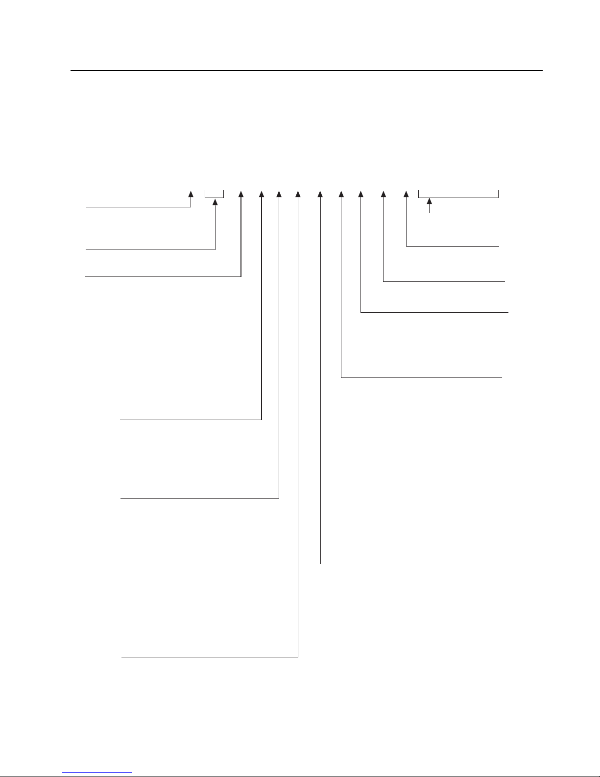
Model Numbering, Charts, and Specifications
Position 1 – Type of Unit
H = Hand-Held Portable
Positions 2 & 3 – Model Series
Position 4 - Frequency Band
Less than 29.7MHz
29.7 to 35.99MHz
36 to 41.99MHz
42 to 50MHz
66 to 80MHz
74 to 90MHz
Product Specific
136 to 162MHz
146 to 178MHz
174 to 210MHz
190 to 235MHz
336 to 410MHz
380 to 470MHz
438 to 482MHz
470 to 520MHz
Dual Band Capable
764 to 870MHz
825 to 870MHz
896 to 941MHz
1.0 to 1.6GHz
1.5 to 2.0GHz
Values given represent range only; they are
not absolute.
Position 5 – Power Level
0 to 0.7 Watts
0.7 to 0.9 Watts
1.0 to 3.9 Watts
4.0 to 5.0 Watts
5.1 to 6.0 Watts
6.1 to 10 Watts
0 to 6 Watts
Position 6 – Physical Packages
RF Modem Operation
Receiver Only
Standard Control; No Display
Standard Control; With Display
Limited Keypad; No Display
Limited Keypad; With Display
Full Keypad; No Display
Full Keypad; With Display
Limited Controls; No Display
Limited Controls; Basic Display
Limited Controls; Limited Display
Rotary Controls; Standard Display
Enhanced Controls; Enhanced Display
Low Profile; No Display
Low Profile; Basic Display
Low Profile; Basic Display, Full Keypad
Position 7 – Channel Spacing
1 = 5kHz
2 = 6.25kHz
3 = 10kHz
4 = 12.5kHz
5 = 15kHz
6 = 20/25kHz
7 = 30kHz
9 = Variable/Programmable
Typical Model Number:
Position:
Position 8 – Primary Operation
Conventional/Simplex
Conventional/Duplex
Trunked Twin Type
Dual Mode Trunked
Dual Mode Trunked/Duplex
Trunked Type I
Trunked Type II
FDMA* Digital Dual Mode
TDMA** Digital Dual Mode
Single Sideband
Global Positioning Satellite Capable
Amplitude Companded Sideband (ACSB)
Programmable
* FDMA = Frequency Division Multiple Access
** TDMA = Time Division Multiple Access
Position 9 – Primary System Type
Conventional
Privacy Plus
Clear SMARTNET
Advanced Conventional Stat-Alert
Enhanced Privacy Plus
Nauganet 888 Series
Japan Specialized Mobile Radio (JSMR)
Multi-Channel Access (MCA)
CoveragePLUS
MPT1327* – Public
MPT1327* – Private
Radiocom
Tone Signalling
Binary Signalling
Phonenet
Programmable
Secure Conventional
Secure SMARTNET
* MPT = Ministry of Posts and Telecommunications
Position 10 – Feature Level
1 = Basic
2 = Limited Package
3 = Limited Plus
4 = Intermediate
5 = Standard Package
6 = Standard Plus
7 = Expanded Package
8 = Expanded Plus
9 = Full Feature/
Programmable
Position 11 – Version
Version Letter (Alpha) – Major Change
Position 12 –
Unique Model Variations
C = Cenelec
N = Standard Package
Positions 13 – 16
SP Model Suffix
1234 5 6 7 8 910111213141516
H97 T GD 9 P W 1 A N S P 0 1
97 = APX 7000
A
B
C
D
F
G
H
J
K
L
M
=
=
=
=
=
=
=
=
=
=
=
P
Q
R
S
T
U
V
W
Y
Z
=
=
=
=
=
=
=
=
=
=
A
B
C
D
E
F
G
=
=
=
=
=
=
=
A
B
C
D
E
F
G
H
J
K
L
M
N
P
Q
R
=
=
=
=
=
=
=
=
=
=
=
=
=
=
=
=
A
B
C
D
E
F
G
H
J
K
L
M
P
=
=
=
=
=
=
=
=
=
=
=
=
=
A
B
C
D
E
F
G
H
J
K
L
M
N
P
Q
W
X
Y
=
=
=
=
=
=
=
=
=
=
=
=
=
=
=
=
=
=
Portable Radio Model Numbering System
Page 18

Sec 1: x ASTRO APX 7000 700–800 MHz and VHF Model Chart
ASTRO APX 7000 700–800 MHz and VHF Model Chart
MODEL NUMBER:
FCC ID:
H97TGD9PW1_N
AZ489FT7036
MODEL DESCRIPTION: 700–800 / VHF, APX 7000
Top Display Model
Dual Display Model
ITEM NUMBER DESCRIPTION
XX01009304001 Sub-Assembly, Main Chassis
X 01009304024 Display, Color
●●01009304004 Grille, Speaker, Black
●●01009304005 Grille, Speaker, Safety Yellow
●●01009304006 Grille, Speaker, Impact Green
XX0375962B01 Screw, Chassis (M2.5 x 0.45 x 31mm)
XX0375962B02 Screw, Chassis (M2.5 x 0.45 x 25mm)
XX0375962B03 Screw, Chassis (M2.5 x 0.45 x 7.3mm)
XX1110027B23 Grease, Fluorocarbon Lubricant
XX1375044C02 Assembly, Control Top
XX1375579B03 Bezel, Outer Top
XX1575250H01 Cover, Universal Connector
X 1575356H01 Cover, Belt Clip, Top Display
XX32009064001 Plug, Controls Flex Support
XX3271829H01 Seal, Battery Connector
XX3275623B02 Pad, Thermal, Outer
XX3275882B01 Seal, Memory Card Portal
XX3371896H01 Label, Grille Top APX 7000
X 3385836D09 Label, Blank, Top Display
XX3875126H01 Cap, Chassis Screw Boss
XX75009299001 Pad, Thermal, Inner
XX7575218H01 Pad, Thermal, Expansion / VOCON
XXMHLN6977_/ MHLN7035_*Assembly, Expansion Board
X MNCN6200_/ MNCN6202_**Assembly, VOCON Board, Dual Display
X MNCN6201_/ MNCN6203_**Assembly, VOCON Board, Top Display
X 01009304011 Assembly, Main Housing, Dual Display, Black
● 01009304007 Assembly, Main Housing, Dual Display, Safety Yellow
● 01009304008 Assembly, Main Housing, Dual Display, Impact Green
● 01009304015 Assembly, Main Housing, Top Display, Black
● 01009304009 Assembly, Main Housing, Top Display, Safety Yellow
● 01009304010 Assembly, Main Housing, Top Display, Impact Green
XXNHN7002_ Assembly, Speaker Module
X NHN7017_ Sub-Assembly, Back Chassis, Dual Display
X NHN7004_ Sub-Assembly, Back Chassis, Top Display
XXMNUR4001_ Assembly, RF Board
ooNNTN8160_ Bluetooth Upgrade Kit
∆∆NUUK6000_ Assembly Bluetooth Option Board
XXPMLN5335_ User Guide CD, APX 7000/ APX 7000XE
Note:
X = Item Included.
● = Option available.
o = Optional.
∆ = Comes with unit equipped with Bluetooth Option Board
• Refer Appendix A for antennas, batteries and other applicable accessories.
*With TI Chipset.
** With PCN Display Vocon.
Page 19

ASTRO APX 7000 700–800 MHz and UHF1 Model Chart Sec 1: xi
ASTRO APX 7000 700–800 MHz and UHF1 Model Chart
MODEL NUMBER:
FCC ID:
H97TGD9PW1_N
AZ489FT7040
MODEL DESCRIPTION: 700–800 / UHF1, APX 7000
Top Display Model
Dual Display Model
ITEM NUMBER DESCRIPTION
XX01009304001 Sub-Assembly, Main Chassis
X 01009304024 Display, Color
●●
●●
●●
XX0375962B01 Screw, Chassis (M2.5 x 0.45 x 31mm)
XX0375962B02 Screw, Chassis (M2.5 x 0.45 x 25mm)
XX0375962B03 Screw, Chassis (M2.5 x 0.45 x 7.3mm)
XX1110027B23 Grease, Fluorocarbon Lubricant
XX1375044C02 Assembly, Control Top
XX1375579B03 Bezel, Outer Top
XX1575250H01 Cover, Universal Connector
X 1575356H01 Cover, Belt Clip, Top Display
XX32009064001 Plug, Controls Flex Support
XX3271829H01 Seal, Battery Connector
XX3275623B02 Pad, Thermal, Outer
XX3275882B01 Seal, Memory Card Portal
XX3371896H01 Label, Grille Top APX 7000
X 3385836D09 Label, Blank, Top Display
XX3875126H01 Cap, Chassis Screw Boss
XX75009299001 Pad, Thermal, Inner
XX7575218H01 Pad, Thermal, Expansion / VOCON
XXMHLN6977_/ MHLN7035_*Assembly, Expansion Board
X MNCN6201_/ MNCN6203_**Assembly, VOCON Board, Top Display
01009304004 Grille, Speaker, Black
01009304005 Grille, Speaker, Safety Yellow
01009304006 Grille, Speaker, Impact Green
X MNCN6200_/ MNCN6202_**Assembly, VOCON Board, Dual Display
● 01009304011 Assembly, Main Housing, Dual Display, Black
● 01009304007 Assembly, Main Housing, Dual Display, Safety Yellow
● 01009304008 Assembly, Main Housing, Dual Display, Impact Green
● 01009304015 Assembly, Main Housing, Top Display, Black
● 01009304009 Assembly, Main Housing, Top Display, Safety Yellow
● 01009304010 Assembly, Main Housing, Top Display, Impact Green
XXNHN7002_ Assembly, Speaker Module
X NHN7017_ Sub-Assembly, Back Chassis, Dual Display
X NHN7004_ Sub-Assembly, Back Chassis, Top Display
XXMNUS4000_ Assembly, RF Board
ooNNTN8160_ Bluetooth Upgrade Kit
∆∆NUUK6000_ Assembly Bluetooth Option Board
XXPMLN5335_ User Guide CD, APX 7000/ APX 7000XE
Note:
X = Item Included.
● = Option available.
o = Optional.
∆ = Comes with unit equipped with Bluetooth Option Board
• Refer Appendix A for antennas, batteries and other applicable accessories.
*With TI Chipset.
** With PCN Display Vocon.
Page 20

Sec 1: xii ASTRO APX 7000 UHF1 and VHF Model Chart
ASTRO APX 7000 UHF1 and VHF Model Chart
MODEL NUMBER:
FCC ID:
H97TGD9PW1_N
AZ489FT4886
MODEL DESCRIPTION: UHF1 / VHF, APX 7000
Top Display Model
Dual Display Model
ITEM NUMBER DESCRIPTION
XX01009304001 Sub-Assembly, Main Chassis
X 01009304024 Display, Color
●●01009304004 Grille, Speaker, Black
●●01009304005 Grille, Speaker, Safety Yellow
●●01009304006 Grille, Speaker, Impact Green
XX0375962B01 Screw, Chassis (M2.5 x 0.45 x 31mm)
XX0375962B02 Screw, Chassis (M2.5 x 0.45 x 25mm)
XX0375962B03 Screw, Chassis (M2.5 x 0.45 x 7.3mm)
XX1110027B23 Grease, Fluorocarbon Lubricant
XX1375044C02 Assembly, Control Top
XX1375579B03 Bezel, Outer Top
XX1575250H01 Cover, Universal Connector
X 1575356H01 Cover, Belt Clip, Top Display
XX32009064001 Plug, Controls Flex Support
XX3271829H01 Seal, Battery Connector
XX3275623B02 Pad, Thermal, Outer
XX3275882B01 Seal, Memory Card Portal
XX3371896H01 Label, Grille Top APX 7000
X 3385836D09 Label, Blank, Top Display
XX3875126H01 Cap, Chassis Screw Boss
XX75009299001 Pad, Thermal, Inner
XX7575218H01 Pad, Thermal, Expansion / VOCON
XXMHLN6977_/ MHLN7035_*Assembly, Expansion Board
X MNCN6200_/ MNCN6202_**Assembly, VOCON Board, Dual Display
X MNCN6201_/ MNCN6203_**Assembly, VOCON Board, Top Display
● 01009304011 Assembly, Main Housing, Dual Display, Black
● 01009304007 Assembly, Main Housing, Dual Display, Safety Yellow
● 01009304008 Assembly, Main Housing, Dual Display, Impact Green
● 01009304015 Assembly, Main Housing, Top Display, Black
● 01009304009 Assembly, Main Housing, Top Display, Safety Yellow
● 01009304010 Assembly, Main Housing, Top Display, Impact Green
XXNHN7002_ Assembly, Speaker Module
X NHN7017_ Sub-Assembly, Back Chassis, Dual Display
X NHN7004_ Sub-Assembly, Back Chassis, Top Display
XXMNUT4000_ Assembly, RF Board
ooNNTN8160_ Bluetooth Upgrade Kit
∆∆NUUK6000_ Assembly Bluetooth Option Board
XXPMLN5335_ User Guide CD, APX 7000/ APX 7000XE
Note:
X = Item Included.
● = Option available.
o = Optional.
∆ = Comes with unit equipped with Bluetooth Option Board
• Refer Appendix A for antennas, batteries and other applicable accessories.
*With TI Chipset.
** With PCN Display Vocon.
Page 21

ASTRO APX 7000 UHF1 and UHF2 Model Chart Sec 1: xiii
ASTRO APX 7000 UHF1 and UHF2 Model Chart
MODEL NUMBER:
FCC ID:
H97TGD9PW1_N
AZ489FT4906
MODEL DESCRIPTION: UHF1 / UHF2, APX 7000
Top Display Model
Dual Display Model
ITEM NUMBER DESCRIPTION
XX01009304001 Sub-Assembly, Main Chassis
X 01009304024 Display, Color
●●01009304004 Grille, Speaker, Black
●●01009304005 Grille, Speaker, Safety Yellow
●●01009304006 Grille, Speaker, Impact Green
XX0375962B01 Screw, Chassis (M2.5 x 0.45 x 31mm)
XX0375962B02 Screw, Chassis (M2.5 x 0.45 x 25mm)
XX0375962B03 Screw, Chassis (M2.5 x 0.45 x 7.3mm)
XX1110027B23 Grease, Fluorocarbon Lubricant
XX1375044C02 Assembly, Control Top
XX1375579B03 Bezel, Outer Top
XX1575250H01 Cover, Universal Connector
X 1575356H01 Cover, Belt Clip, Top Display
XX32009064001 Plug, Controls Flex Support
XX3271829H01 Seal, Battery Connector
XX3275623B02 Pad, Thermal, Outer
XX3275882B01 Seal, Memory Card Portal
XX3371896H01 Label, Grille Top APX 7000
X 3385836D09 Label, Blank, Top Display
XX3875126H01 Cap, Chassis Screw Boss
XX75009299001 Pad, Thermal, Inner
XX7575218H01 Pad, Thermal, Expansion / VOCON
XXMHLN6977_/ MHLN7035_*Assembly, Expansion Board
X MNCN6200_/ MNCN6202_**Assembly, VOCON Board, Dual Display
X MNCN6201_/ MNCN6203_**Assembly, VOCON Board, Top Display
● 01009304011 Assembly, Main Housing, Dual Display, Black
● 01009304007 Assembly, Main Housing, Dual Display, Safety Yellow
● 01009304008 Assembly, Main Housing, Dual Display, Impact Green
● 01009304015 Assembly, Main Housing, Top Display, Black
● 01009304009 Assembly, Main Housing, Top Display, Safety Yellow
● 01009304010 Assembly, Main Housing, Top Display, Impact Green
XXNHN7002_ Assembly, Speaker Module
X NHN7017_ Sub-Assembly, Back Chassis, Dual Display
X NHN7004_ Sub-Assembly, Back Chassis, Top Display
XXMNUE7367_ Assembly, RF Board
ooNNTN8160_ Bluetooth Upgrade Kit
∆∆NUUK6000_ Assembly Bluetooth Option Board
XXPMLN5335_ User Guide CD, APX 7000/ APX 7000XE
Note:
X = Item Included.
● = Option available.
o = Optional.
∆ = Comes with unit equipped with Bluetooth Option Board
• Refer Appendix A for antennas, batteries and other applicable accessories.
*With TI Chipset.
** With PCN Display Vocon.
Page 22

Sec 1: xiv ASTRO APX 7000 700–800 MHz and UHF2 Model Chart
ASTRO APX 7000 700–800 MHz and UHF2 Model Chart
MODEL NUMBER:
FCC ID:
H97TGD9PW1_N
AZ489FT7042
MODEL DESCRIPTION: 700–800 / UHF2, APX 7000
Top Display Model
Dual Display Model
ITEM NUMBER DESCRIPTION
XX01009304001 Sub-Assembly, Main Chassis
X 01009304024 Display, Color
●●01009304004 Grille, Speaker, Black
●●01009304005 Grille, Speaker, Safety Yellow
●●01009304006 Grille, Speaker, Impact Green
XX0375962B01 Screw, Chassis (M2.5 x 0.45 x 31mm)
XX0375962B02 Screw, Chassis (M2.5 x 0.45 x 25mm)
XX0375962B03 Screw, Chassis (M2.5 x 0.45 x 7.3mm)
XX1110027B23 Grease, Fluorocarbon Lubricant
XX1375044C02 Assembly, Control Top
XX1375579B03 Bezel, Outer Top
XX1575250H01 Cover, Universal Connector
X 1575356H01 Cover, Belt Clip, Top Display
XX32009064001 Plug, Controls Flex Support
XX3271829H01 Seal, Battery Connector
XX3275623B02 Pad, Thermal, Outer
XX3275882B01 Seal, Memory Card Portal
XX3371896H01 Label, Grille Top APX 7000
X 3385836D09 Label, Blank, Top Display
XX3875126H01 Cap, Chassis Screw Boss
XX75009299001 Pad, Thermal, Inner
XX7575218H01 Pad, Thermal, Expansion / VOCON
XXMHLN6977_/ MHLN7035_*Assembly, Expansion Board
X MNCN6200_/ MNCN6202_**Assembly, VOCON Board, Dual Display
X MNCN6201_/ MNCN6203_**Assembly, VOCON Board, Top Display
● 01009304011 Assembly, Main Housing, Dual Display, Black
● 01009304007 Assembly, Main Housing, Dual Display, Safety Yellow
● 01009304008 Assembly, Main Housing, Dual Display, Impact Green
● 01009304015 Assembly, Main Housing, Top Display, Black
● 01009304009 Assembly, Main Housing, Top Display, Safety Yellow
● 01009304010 Assembly, Main Housing, Top Display, Impact Green
XXNHN7002_ Assembly, Speaker Module
X NHN7017_ Sub-Assembly, Back Chassis, Dual Display
X NHN7004_ Sub-Assembly, Back Chassis, Top Display
XXMNUS4002_ Assembly, RF Board
ooNNTN8160_ Bluetooth Upgrade Kit
∆∆NUUK6000_ Assembly Bluetooth Option Board
XXPMLN5335_ User Guide CD, APX 7000/ APX 7000XE
Note:
X = Item Included.
● = Option available.
o = Optional.
∆ = Comes with unit equipped with Bluetooth Option Board
• Refer Appendix A for antennas, batteries and other applicable accessories.
*With TI Chipset.
** With PCN Display Vocon.
Page 23

ASTRO APX 7000 UHF2 and VHF Model Chart Sec 1: xv
ASTRO APX 7000 UHF2 and VHF Model Chart
MODEL NUMBER:
FCC ID:
H97TGD9PW1_N
AZ489FT4893
MODEL DESCRIPTION: UHF2 / VHF, APX 7000
Top Display Model
Dual Display Model
ITEM NUMBER DESCRIPTION
XX01009304001 Sub-Assembly, Main Chassis
X 01009304024 Display, Color
●●01009304004 Grille, Speaker, Black
●●01009304005 Grille, Speaker, Safety Yellow
●●01009304006 Grille, Speaker, Impact Green
XX0375962B01 Screw, Chassis (M2.5 x 0.45 x 31mm)
XX0375962B02 Screw, Chassis (M2.5 x 0.45 x 25mm)
XX0375962B03 Screw, Chassis (M2.5 x 0.45 x 7.3mm)
XX1110027B23 Grease, Fluorocarbon Lubricant
XX1375044C02 Assembly, Control Top
XX1375579B03 Bezel, Outer Top
XX1575250H01 Cover, Universal Connector
X 1575356H01 Cover, Belt Clip, Top Display
XX32009064001 Plug, Controls Flex Support
XX3271829H01 Seal, Battery Connector
XX3275623B02 Pad, Thermal, Outer
XX3275882B01 Seal, Memory Card Portal
XX3371896H01 Label, Grille Top APX 7000
X 3385836D09 Label, Blank, Top Display
XX3875126H01 Cap, Chassis Screw Boss
XX75009299001 Pad, Thermal, Inner
XX7575218H01 Pad, Thermal, Expansion / VOCON
XXMHLN6977_/ MHLN7035_*Assembly, Expansion Board
X MNCN6200_/ MNCN6202_**Assembly, VOCON Board, Dual Display
X MNCN6201_/ MNCN6203_**Assembly, VOCON Board, Top Display
● 01009304011 Assembly, Main Housing, Dual Display, Black
● 01009304007 Assembly, Main Housing, Dual Display, Safety Yellow
● 01009304008 Assembly, Main Housing, Dual Display, Impact Green
● 01009304015 Assembly, Main Housing, Top Display, Black
● 01009304009 Assembly, Main Housing, Top Display, Safety Yellow
● 01009304010 Assembly, Main Housing, Top Display, Impact Green
XXNHN7002_ Assembly, Speaker Module
X NHN7017_ Sub-Assembly, Back Chassis, Dual Display
X NHN7004_ Sub-Assembly, Back Chassis, Top Display
XXMNUT4004_ Assembly, RF Board
ooNNTN8160_ Bluetooth Upgrade Kit
∆∆NUUK6000_ Assembly Bluetooth Option Board
XXPMLN5335_ User Guide CD, APX 7000/ APX 7000XE
Note:
X = Item Included.
● = Option available.
o = Optional.
∆ = Comes with unit equipped with Bluetooth Option Board
• Refer Appendix A for antennas, batteries and other applicable accessories.
*With TI Chipset.
** With PCN Display Vocon.
Page 24

Sec 1: xvi Specifications for VHF Radios
Specifications for VHF Radios
All specifications are per Telecommunications Industries Association TIA-603 unless otherwise
noted.
GENERAL RECEIVER TRANSMITTER
Temperature Range:
Operating: -30°C to +60°C
Storage: -40°C to +85°C
Power Supply:
Nickel-Metal-Hydride Battery (NiMH)
or Lithium-Ion Battery (Li-Ion)
Battery Voltage:
Nominal: 7.5 Vdc
Range: 6 to 9 Vdc
Transmit Current Drain (Typical): 2398 mA
Receive Current Drain (Rated Audio): 273 mA
Standby Current Drain: 142 mA
Recommended IMPRES Battery:
Li-Ion (2900mAh, IP67): NNTN7038_
or Li-Ion (2150mAh, Slim, IP67): PMNN4403_
or Li-Ion (4200mAh, Rugged): NNTN7034_
or Li-Ion (4100mAh, Rugged)
2
: NNTN7033_
or NiMH (2100mAh, IP67): NNTN7037_
or NiMH (2100mAh, Rugged): NNTN7573_
or NiMH (2000mAh, IP67)
or Li-Ion (2300mAh, Rugged)
or NiMH (2000mAh, Rugged)
Dimensions
3
:
2
: NNTN7036_
2
: NNTN8092_
2
: NNTN7035_
Without Battery (Radio Only):
H = 6.29" (159.7 mm)
4
= 2.98" (75.6 mm) / 2.31" (58.6 mm)
W
5
D
= 1.25" (31.7 mm) / 1.40" (35.6 mm)
With Li-Ion Battery
H = 6.55" (166.3 mm)
4
= 2.98" (75.6 mm) / 2.31" (58.6 mm)
W
5
= 1.65" (41.8 mm) / 1.40" (35.6 mm)
D
With NiMH Battery
H = 8.55" (217.1 mm)
4
= 2.98" (75.6 mm) / 2.31" (58.6 mm)
W
5
= 1.65" (41.8 mm) / 1.40" (35.6 mm)
D
6
:
7
:
Weight: (w/o Antenna):
Less Battery: 12.2 oz (346 g)
With Li-Ion
With Li-Ion Ultra High Cap
With NiMH
6
: 18.7 oz (530 g)
7
: 24.0 oz (681 g)
8
: 22.9 oz (648 g)
Frequency Range: 136–174 MHz
Bandwidth: 38 MHz
Analog Sensitivity (typical)
(12 dB SINAD): 0.216 µV
Digital Sensitivity (typical)
(1% BER): 0.277 µV
(5% BER): 0.188 µV
Intermodulation Rejection (typical): 80.5 dB
9
Selectivity
(typical):
(25 kHz Channel): 79.3 dB
(12.5 kHz Channel): 70 dB
1
Spurious Rejection (typical): 93.2 dB
Frequency Stability
(-30+60°C; 25°C reference): ±0.0001%
Rated Audio:
Internal Speaker: 1 W
External Speaker: 500 mW
FM Hum and Noise (typical):
25 kHz -53.8 dB
12.5 kHz -48 dB
Distortion (typical): 1.2%
Channel Spacing: 12.5/20/25 kHz
Frequency Range: 136–174 MHz
RF Power:
136–174 MHz: 1–6 Watts
Frequency Stability
(-30 to +60°C; 25°C ref.): ±0.0001%
Emission
(typical conducted): -75 dBc
FM Hum and Noise (typical):
25 kHz -47 dB
12.5 kHz -45 dB
Distortion (typical): 0.50%
Modulation Limiting: 25 kHz chnls ±5.0 kHz
20 kHz chnls ±4.0 kHz
12.5 kHz chnls ±2.5 kHz
ACPR (typical): 25 kHz -78 dBc
12.5 kHz -68 dBc
Emissions Designators:
11K0F3E, 16K0F3E, 8K10F1D, 8K10F1E,
8K10F1W, 20K0F1E
Note:
1. Default APX 7000 Battery
2. Intrinsically Safe.
3. H = Height; W = Width; D = Depth.
4. W = (Width @ Top) / (Width @ PTT).
5. D = (Depth @ Bottom) / (Depth @ PTT).
6. Measured with NNTN7038_.
7. Measured with NNTN7035_.
8. Measured with NNTN7033_.
9. Single tone test.
Specifications subject to change without notice.
Page 25

Specifications for 700–800 MHz Radios Sec 1: xvii
Specifications for 700–800 MHz Radios
All specifications are per Telecommunications Industries Association TIA-603 unless otherwise
noted.
GENERAL RECEIVER TRANSMITTER
Temperature Range:
Operating: -30°C to +60°C
Storage: -40°C to +85°C
Power Supply:
Nickel-Metal-Hydride Battery (NiMH)
or Lithium-Ion Battery (Li-Ion)
Battery Voltage:
Nominal: 7.5 Vdc
Range: 6 to 9 Vdc
Transmit Current Drain (Typical): 1499 mA
Receive Current Drain (Rated Audio): 278 mA
Standby Current Drain: 148 mA
Recommended IMPRES Battery:
Li-Ion (2900mAh, IP67): NNTN7038_
or Li-Ion (2150mAh, Slim, IP67): PMNN4403_
or Li-Ion (4200mAh, Rugged): NNTN7034_
or Li-Ion (4100mAh, Rugged)
2
: NNTN7033_
or NiMH (2100mAh, IP67): NNTN7037_
or NiMH (2100mAh, Rugged): NNTN7573_
or NiMH (2000mAh, IP67)
or Li-Ion (2300mAh, Rugged)
or NiMH (2000mAh, Rugged)
Dimensions
3
:
2
: NNTN7036_
2
: NNTN8092_
2
: NNTN7035_
Without Battery (Radio Only):
H = 6.29" (159.7 mm)
4
= 2.98" (75.6 mm) / 2.31" (58.6 mm)
W
5
D
= 1.25" (31.7 mm) / 1.40" (35.6 mm)
With Li-Ion Battery
H = 6.55" (166.3 mm)
4
= 2.98" (75.6 mm) / 2.31" (58.6 mm)
W
5
= 1.65" (41.8 mm) / 1.40" (35.6 mm)
D
With NiMH Battery
H = 8.55" (217.1 mm)
4
= 2.98" (75.6 mm) / 2.31" (58.6 mm)
W
5
= 1.65" (41.8 mm) / 1.40" (35.6 mm)
D
6
:
7
:
Frequency Range:
700 MHz: 763–776 MHz
800 MHz: 851–870 MHz
Bandwidth:
700 MHz: 13 MHz
800 MHz: 19 MHz
Analog Sensitivity (typical)
(12 dB SINAD): 0.25 µV
Digital Sensitivity (typical)
(1% BER: 700/ 800 MHz): 0.347/ 0.333 µV
(5% BER): 0.251 µV
Intermodulation Rejection (typical): 80 dB
1
Selectivity
9
(typical):
(25 kHz Channel): 75.7 dB
(12.5 kHz Channel): 67 .5 dB
Spurious Rejection (typical): 76.6 dB
Frequency Stability
(-30+60°C; 25°C reference): ±0.0001%
Rated Audio:
Internal Speaker: 1 W
External Speaker: 500 mW
FM Hum and Noise (typical):
25 kHz -54 dB
12.5 kHz -48 dB
Distortion (typical): 0.9%
Channel Spacing: 12.5/20/25 kHz
Frequency Range:
700 MHz: 763–776; 793–806 MHz
800 MHz: 806–825; 851–870 MHz
RF Power:
700 MHz: 1–2.7 Watts
800 MHz: 1–3 Watts
Frequency Stability
(-30 to +60°C; 25°C ref.):
700 MHz: ±0.0001%
800 MHz: ±0.0001%
Emission
(typical conducted)): -75 dBc
FM Hum and Noise (typical)
25 kHz chnls (700/ 800 MHz): -48 / -47 dB
12.5 kHz chnls (700/ 800 MHz): -46 / -45 dB
Distortion (typical):
700 MHz: 0.60%
800 MHz: 1%
Modulation Limiting: 25 kHz chnls ±5.0 kHz
20 kHz chnls ±4.0 kHz
12.5 kHz chnls ±2.5 kHz
ACPR (typical): 25 kHz -78 dBc
12.5 kHz -68 dBc
Emissions Designators:
11K0F3E, 16K0F3E, 8K10F1D, 8K10F1E,
8K10F1W, 20K0F1E
Weight: (w/o Antenna):
Less Battery: 12.2 oz (346 g)
With Li-Ion
With Li-Ion Ultra High Cap
With NiMH
6
: 18.7 oz (530 g)
7
: 24.0 oz (681 g)
8
: 22.9 oz (648 g)
Note:
1. Default APX 7000 Battery
2. Intrinsically Safe.
3. H = Height; W = Width; D = Depth.
4. W = (Width @ Top) / (Width @ PTT).
5. D = (Depth @ Bottom) / (Depth @ PTT).
6. Measured with NNTN7038_.
7. Measured with NNTN7035_.
8. Measured with NNTN7033_.
9. Single tone test.
Specifications subject to change without notice.
Page 26

Sec 1: xviii Specifications for UHF1 Radios
Specifications for UHF1 Radios
All specifications are per Telecommunications Industries Association TIA-603 unless otherwise
noted.
NOTE: Per the FCC Narrowbanding rules, new products (APX7000 UHF1 / UHF2) submitted for FCC
certification after January 1, 2011 are restricted from being granted certification at 25 kHz for
United States – State and Local Markets only.
GENERAL RECEIVER TRANSMITTER
Temperature Range:
Operating: -30°C to +60°C
Storage: -40°C to +85°C
Power Supply:
Battery Voltage:
Nominal: 7.5 Vdc
Range: 6 to 9 Vdc
Transmit Current Drain (Typical): 2060 mA
Receive Current Drain (Rated Audio): 273 mA
Standby Current Drain: 142 mA
Recommended IMPRES Battery:
Li-Ion (2900mAh, IP67): NNTN7038_
or Li-Ion (2150mAh, Slim, IP67): PMNN4403_
or Li-Ion (4200mAh, Rugged): NNTN7034_
or Li-Ion (4100mAh, Rugged)
or NiMH (2100mAh, IP67): NNTN7037_
or NiMH (2100mAh, Rugged): NNTN7573_
or NiMH (2000mAh, IP67)
or Li-Ion (2300mAh, Rugged)
or NiMH (2000mAh, Rugged)
Dimensions
Without Battery (Radio Only):
H = 6.29" (159.7 mm)
W
D
With Li-Ion Battery
H = 6.55" (166.3 mm)
W
D
With NiMH Battery
H = 8.55" (217.1 mm)
W
D
Weight: (w/o Antenna):
Less Battery: 12.2 oz (346 g)
With Li-Ion6: 18.7 oz (530 g)
With Li-Ion Ultra High Cap
With NiMH
Nickel-Metal-Hydride Battery (NiMH)
or Lithium-Ion Battery (Li-Ion)
2
: NNTN7033_
2
: NNTN7036_
2
: NNTN8092_
2
: NNTN7035_
3
:
4
= 2.98" (75.6 mm) / 2.31" (58.6 mm)
5
= 1.25" (31.7 mm) / 1.40" (35.6 mm)
4
= 2.98" (75.6 mm) / 2.31" (58.6 mm)
5
= 1.65" (41.8 mm) / 1.40" (35.6 mm)
4
= 2.98" (75.6 mm) / 2.31" (58.6 mm)
5
= 1.65" (41.8 mm) / 1.40" (35.6 mm)
6
:
7
:
8
7
: 24.0 oz (681 g)
: 22.9 oz (648 g)
Frequency Range: 380–470 MHz
Bandwidth: 90 MHz
Analog Sensitivity (typical)
(12 dB SINAD): 0.234 µV
Digital Sensitivity (typical)
(1% BER): 0.307 µV
(5% BER): 0.207 µV
Intermodulation Rejection (typical): 80.2 dB
Selectivity
1
Spurious Rejection (typical): 80.3 dB
Frequency Stability
Rated Audio:
FM Hum and Noise (typical):
Distortion (typical): 0.91 %
Channel Spacing: 12.5/20/25 kHz
9
(25 kHz Channel): 78.3 dB
(12.5 kHz Channel): 68.1 dB
(-30+60°C; 25°C reference): ±0.0001%
Internal Speaker: 1 W
External Speaker: 500 mW
(typical):
25 kHz -53.5 dB
12.5 kHz -47.4 dB
Frequency Range: 380–470 MHz
RF Power:
380–470 MHz: 1–5 Watts
Frequency Stability
(-30 to +60°C; 25°C ref.): ±0.0001%
Emission
(typical conducted)): -75 dBc
FM Hum and Noise (typical):
25 kHz -47 dB
12.5 kHz -45 dB
Distortion (typical): 0.50%
Modulation Limiting: 25 kHz chnls ±5.0 kHz
20 kHz chnls ±4.0 kHz
12.5 kHz chnls ±2.5 kHz
ACPR (typical): 25 kHz -75 dBc
12.5 kHz -68 dBc
Emissions Designators:
11K0F3E, 16K0F3E, 8K10F1D, 8K10F1E,
8K10F1W, 20K0F1E
Note:
1. Default APX 7000 Battery
2. Intrinsically Safe.
3. H = Height; W = Width; D = Depth.
4. W = (Width @ Top) / (Width @ PTT).
5. D = (Depth @ Bottom) / (Depth @ PTT).
6. Measured with NNTN7038_.
7. Measured with NNTN7035_.
8. Measured with NNTN7033_.
9. Single tone test.
Specifications subject to change without notice.
Page 27

Specifications for UHF2 Radios Sec 1: xix
Specifications for UHF2 Radios
All specifications are per Telecommunications Industries Association TIA-603 unless otherwise
noted.
NOTE: Per the FCC Narrowbanding rules, new products (APX7000 UHF1 / UHF2) submitted for FCC
certification after January 1, 2011 are restricted from being granted certification at 25 kHz for
United States – State and Local Markets only
GENERAL RECEIVER TRANSMITTER
Temperature Range:
Operating: -30°C to +60°C
Storage: -40°C to +85°C
Power Supply:
Battery Voltage:
Nominal: 7.5 Vdc
Range: 6 to 9 Vdc
Transmit Current Drain (Typical): 2100 mA
Receive Current Drain (Rated Audio): 268 mA
Standby Current Drain: 137 mA
Recommended IMPRES Battery:
Li-Ion (2900mAh, IP67): NNTN7038_
or Li-Ion (2150mAh, Slim, IP67): PMNN4403_
or Li-Ion (4200mAh, Rugged): NNTN7034_
or Li-Ion (4100mAh, Rugged)
or NiMH (2100mAh, IP67): NNTN7037_
or NiMH (2100mAh, Rugged): NNTN7573_
or NiMH (2000mAh, IP67)
or Li-Ion (2300mAh, Rugged)
or NiMH (2000mAh, Rugged)
Dimensions
Without Battery (Radio Only):
H = 6.29" (159.7 mm)
W
D
With Li-Ion Battery
H = 6.55" (166.3 mm)
W
D
With NiMH Battery
H = 8.55" (217.1 mm)
W
D
Weight: (w/o Antenna):
Less Battery: 12.2 oz (346 g)
With Li-Ion6: 18.7 oz (530 g)
With Li-Ion Ultra High Cap
With NiMH
Nickel-Metal-Hydride Battery (NiMH)
or Lithium-Ion Battery (Li-Ion)
2
: NNTN7033_
2
: NNTN7036_
2
: NNTN8092_
2
: NNTN7035_
3
:
4
= 2.98" (75.6 mm) / 2.31" (58.6 mm)
5
= 1.25" (31.7 mm) / 1.40" (35.6 mm)
4
= 2.98" (75.6 mm) / 2.31" (58.6 mm)
5
= 1.65" (41.8 mm) / 1.40" (35.6 mm)
4
= 2.98" (75.6 mm) / 2.31" (58.6 mm)
5
= 1.65" (41.8 mm) / 1.40" (35.6 mm)
6
:
7
:
8
7
: 24.0 oz (681 g)
: 22.9 oz (648 g)
Frequency Range: 450–520 MHz
Bandwidth: 70 MHz
Analog Sensitivity (typical)
(12 dB SINAD): 0.234 µV
Digital Sensitivity (typical)
(1% BER): 0.307 µV
(5% BER): 0.207 µV
Intermodulation Rejection (typical): 80.2 dB
Selectivity
1
Spurious Rejection (typical): 80.3 dB
Frequency Stability
Rated Audio:
FM Hum and Noise (typical):
Distortion (typical): 0.91 %
Channel Spacing: 12.5/20/25 kHz
9
(25 kHz Channel): 78.3 dB
(12.5 kHz Channel): 67 .5 dB
(-30+60°C; 25°C reference): ±0.0001%
Internal Speaker: 1 W
External Speaker: 500 mW
(typical):
25 kHz -53.5 dB
12.5 kHz -47.4 dB
Frequency Range: 450–520 MHz
RF Power:
450–520 MHz: 1–5 Watts
Frequency Stability
(-30 to +60°C; 25°C ref.): ±0.0001%
Emission (
typical conducted)): -75 dBc
FM Hum and Noise (typical):
25 kHz -47 dB
12.5 kHz -45 dB
Distortion (typical): 0.50%
Modulation Limiting: 25 kHz chnls ±5.0 kHz
20 kHz chnls ±4.0 kHz
12.5 kHz chnls ±2.5 kHz
ACPR (typical): 25 kHz -75 dBc
12.5 kHz -68 dBc
Emissions Designators:
11K0F3E, 16K0F3E, 8K10F1D, 8K10F1E,
8K10F1W, 20K0F1E
Note:
1. Default APX 7000 Battery
2. Intrinsically Safe.
3. H = Height; W = Width; D = Depth.
4. W = (Width @ Top) / (Width @ PTT).
5. D = (Depth @ Bottom) / (Depth @ PTT).
6. Measured with NNTN7038_.
7. Measured with NNTN7035_.
8. Measured with NNTN7033_.
9. Single tone test.
Specifications subject to change without notice.
Page 28

Sec 1: xx Specifications for UHF2 Radios
Notes
Page 29
Chapter 1 Introduction
This manual contains information needed for Levels One and Two radio servicing. Level One
servicing consists of radio programming, radio alignment, knobs replacement, and installation and
removal of the antenna, belt clip, battery, and universal connector cover. Level Two servicing covers
disassembly and reassembly of the radio to replace circuit boards.
1.1 Manual Contents
Included in this manual are radio specifications for the VHF(136–174 MHz), UHF1 (380–470 MHz),
UHF2 (450–520 MHz) and 764–870 MHz frequency bands, a general description of
ASTRO APX 7000 models, recommended test equipment, service aids, radio alignment procedures,
general maintenance recommendations, procedures for assembly and disassembly, and exploded
views and parts lists.
1.2 Notations Used in This Manual
Throughout the text in this publication, you will notice the use of note, caution, warning, and danger
notations. These notations are used to emphasize that safety hazards exist, and due care must be
taken and observed.
NOTE: An operational procedure, practice, or condition that is essential to emphasize.
CAUTION indicates a potentially hazardous situation which, if
not avoided, might
WARNING indicates a potentially hazardous situation
which, if not avoided, could
result in equipment damage.
result in death or injury.
DANGER indicates an imminently hazardous
situation which, if not avoided, will
result in death or
injury.
Page 30
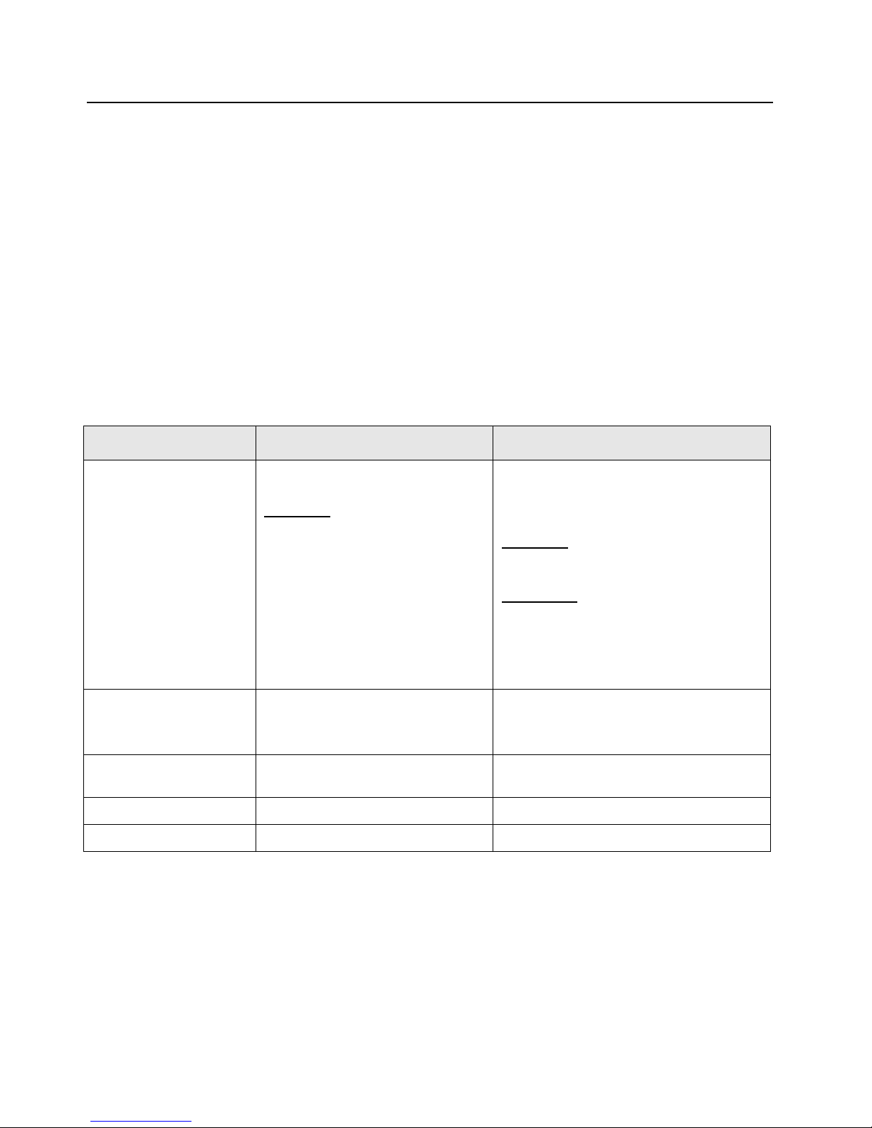
Sec 1: 1-2 Introduction: Radio Description
1.3 Radio Description
The ASTRO APX 7000 radios are among the most sophisticated two-way radios available. These
dual band radios are capable of operating in both VHF (136–174 MHz) and 764–870 MHz frequency
bands, UHF1 (380–470 MHz) and 764–870 MHz frequency bands, VHF (136–174 MHz) and UHF1
(380–470 MHz) frequency bands, UHF1 (380–450 MHz) and UHF2 (450–520 MHz) frequency
bands, UHF2 (450–520 MHz) and 764–870 MHz frequency bands, and, VHF (136–174 MHz) and
UHF2 (450–520 MHz) frequency bands.
The ASTRO APX 7000 radio provides improved voice quality across more coverage area. The digital
process, called embedded signaling, intermixes system signaling information with digital voice,
resulting in improved system reliability and the capability of supporting a multitude of advanced
features.
ASTRO APX 7000 radios are available in two configurations – Top Display and Dual Display.
Table 1-1 describes their basic features.
Table 1-1. ASTRO APX 7000 Basic Features
Feature Top-Di spl ay Dual-Display
Display LCD (monochrome)
Fully bit-mapped
Top Display:
• 1 line of text (8 characters per line)
• 1 line of icons
Keypad None 3 x 2 Menu Buttons
Channel Capability 96 (Basic Zone Bank)
1200 (Enhanced Zone Bank)
Dialing from Prestored List No Yes
Programmable Softkeys No Yes
LCD
• Top Display – monochrome
• Front Display – color
Fully bit-mapped
Top Display
• 1 line of text (8 characters per line)
• 1 line of icons
Front Display:
Dispatch Mode:
List Feature Mode:
• 2 lines of icons
(with 4-way Navigation button),
3 x 4 Alphanumeric Keypad
2000
:
• 5 lines of text (14 characters per line)
• 8 lines of text (14 characters per line)
1.4 FLASHport
®
The ASTRO APX 7000 radio utilizes Motorola’s FLASHport technology. FLASHport makes it
possible to add software that drives the radio’s capabilities both at the time of purchase and later on.
Previously, changing a radio’s features and capabilities meant significant modifications or buying a
new radio. But now, similar to how a computer can be loaded with different software, the radio’s
features and capabilities can be upgraded with FLASHport software.
Page 31

Chapter 2 Basic Maintenance
This chapter describes preventive maintenance and handling precautions. Each of these topics
provides information vital to the successful operation and maintenance of your radio.
2.1 General Maintenance
In order to avoid operating outside the limits set by the FCC, we recommend that you align the
ASTRO APX 7000 radio’s reference oscillator every time the radio is taken apart, or once per year,
whichever comes first. Checking this parameter when the product is placed in service is especially
important if the product has been in storage for a significant period of time (6 months or more)
between being shipped from the factory and commissioned for service. (See Section “6.5.1
Reference Oscillator Alignment” on page 1:6-4). Periodic visual inspection and cleaning is also
recommended.
For APX 7000 R (Ruggedized) Radios – Radio submergibility should be checked annually by
qualified service technicians.
2.1.1 Inspection
Check that the external surfaces of the radio are clean and that all external controls and switches are
functional. A detailed inspection of the interior electronic circuitry is not needed.
2.1.2 Cleaning
The following procedures describe the recommended cleaning agents and the methods to be used
when cleaning the external surfaces of the radio. External surfaces include the housing assembly
and battery case. These surfaces should be cleaned whenever a periodic visual inspection reveals
the presence of smudges, grease, and/or grime.
The only recommended agent for cleaning the external radio surfaces is a 0.5% solution of a mild
dishwashing detergent in water.
The detergent-water solution should be applied sparingly with a stiff, non-metallic, short-bristled
brush to work all loose dirt away from the radio. A soft, absorbent, lintless cloth or tissue should be
used to remove the solution and dry the radio. Make sure that no water remains entrapped near the
connectors, cracks, or crevices.
Use all chemicals as prescribed by the manufacturer. Be sure to follow all
safety precautions as defined on the label or material safety data sheet.
The effects of certain chemicals and their vapors can have harmful results
on certain plastics. Aerosol sprays, tuner cleaners, and other chemicals
should be avoided.
Page 32

Sec 1: 2-2 Basic Maintenance: Handling Precautions
2.2 Handling Precautions
Complementary metal-oxide semiconductor (CMOS) devices, and other high-technology devices,
are used in this family of radios. While the attributes of these devices are many, their characteristics
make them susceptible to damage by electrostatic discharge (ESD) or high-voltage charges.
Damage can be latent, resulting in failures occurring weeks or months later. Therefore, special
precautions must be taken to prevent device damage during disassembly, troubleshooting, and
repair. Handling precautions are mandatory for this radio, and are especially important in lowhumidity conditions.
• The APX 7000 radio has a vent port that allows for pressure equalization
in the radio. Never poke this vent with any objects, such as needles,
tweezers, or screwdrivers. This could create a leak path into the radio and,
in the case of APX 7000 R radios, the radio’s submergibility will be lost.
• The pressure equalization vent is located under the main speaker grille
near the top left side. Never obstruct or cover the small opening on the top
left with any object, including a label. Ensure that no oily substances come
in contact with this vent.
•(APX 7000 R Radios Only) The APX 7000 R radio is designed to be
submerged to a maximum depth of six (6) feet, with a maximum
submersion time of 2 hours per U.S. MIL-STD. Exceeding either
maximum limit may result in damage to the radio. For specific U.S.
MIL-STD details, see Section “8.10 Ensuring Radio Submergibility” on
page 1:8-39.
2.2.1 APX 7000 R Radios Only
If the radio battery contact area has been submerged in water, dry and clean the radio battery
contacts before attaching a battery to the radio. Otherwise, the water could short-circuit the radio.
If the radio has been submerged in water, shake the radio briskly so that any water that is trapped
inside the speaker grille and microphone port can be removed. Otherwise, the water will decrease
the audio quality of the radio.
Page 33

Chapter 3 Basic Theory of Operation
This chapter discusses the basic operational theory of the ASTRO APX 7000 radio, which is a
wideband, synthesized radio available in the VHF (136–174 MHz), UHF1 (380–470 MHz),
UHF2 (450–520 MHz), 764 to 870 MHz, VHF/764 to 870 MHz, UHF1/764 to 870 MHz, VHF/UHF1,
UHF1/UHF2, UHF2/764 to 870 MHz and VHF/UHF2, frequency bands.
All ASTRO APX 7000 radios are capable of both analog operation (12.5 kHz or 25 kHz bandwidths),
ASTRO mode (digital) operation (12.5 kHz only) and X2-TDMA mode (25 kHz only).
3.1 Major Assemblies
The ASTRO APX 7000 radio includes the following major assemblies (see Figure 3-1):
• VOCON Board – contains a dual-core processor which includes both the microcontroller unit
(MCU) and a digital signal processor (DSP) core, the processor's memory devices, an audio
and power supply support integrated circuit (IC), a digital support IC, external audio power
amplifier, and Type III secure IC.
• Transceiver (XCVR) Board – contains all transmit, receive, and frequency generation circuitry,
including the digital receiver back-end IC and the reference oscillator.
• Expander Board – contains the internal audio power amplifier circuitry and the Global
Positioning System (GPS) IC and support circuitry.
• Bluetooth Board – contains a microprocessor and memory, Bluetooth circuitry, MPP (Motorola
Proximity Pairing) circuitry, and an accelerometer.
• Top Display – 112 pixels x 32 pixels, transflective monochrome liquid crystal display (LCD).
• Control Top – contains five switches: On/Off & Volume Knob, a 16 position Channel/Frequency
Knob with concentric 2 position switch (for Secure Enable/Disable operation), a 3 position
toggle switch for Zone Selection, and a push button switch used for Emergency calling. The
control top also includes an TX/RX LED that is solid amber upon receive, red on PTT, and
blinks amber on secure TX/RX.
• Front Display (Dual-Display Version only) – 320 pixels x 240 pixels, transflective color LCD.
• Keypad (Dual-Display Version Only) – Dual-Display version has a 3 x 2 Menu keypad with
4-way navigation button, and a 3 x 4 alphanumeric keypad.
Page 34

Sec 1: 3-2 Basic Theory of Operation: Major Assemblies
Antenna
Expander
Board
14
External accessory connector
External antenna
60
40
Front display*
60
Transceiver VoCon
Board Board
40
Keypad**
20
50 20
Top display
Controls top
30
60
Option
Board
Note:
* Applicable to model with Front Display and
VOCON Board MNCN6200.
** Applicable to model with Front Display.
Figure 3-1. APX 7000 Overall Block Diagram (VOCON Board MNCN6200/ MNCN6201)
Antenna
Expander
Board
14
External accessory connector
External antenna
60
50
Front display*
80
Transceiver VoCon
Board Board
40
Keypad**
30
50 20
Top display
Controls top
30
60
Option
Board
Note:
* Applicable to model with Front Display and
VOCON Board MNCN6202.
** Applicable to model with Front Display.
Figure 3-2. APX 7000 Overall Block Diagram (VOCON Board MNCN6202/ MNCN6203)
Page 35

Basic Theory of Operation: Analog Mode of Operation Sec 1: 3-3
SW
2:1
700/800
VHF
Abacus III
2nd
LO
18Mhz
CLK
CLK
Dec.
Filter
LO
ADC ΣΔ
SW
2:1
PER
SP3T
AUX
DPLXR
To
RF/Vocon
Connector
SSI
RMT Port
SW
2:1
700/800
UHF1
Abacus III
2nd
LO
18Mhz
CLK
CLK
Dec.
Filter
LO
ADC ΣΔ
SW
2:1
PER
SP3T
AUX
DPLXR
To
RF/Vocon
Connector
SSI
RMT Port
3.2 Analog Mode of Operation
This section provides an overview of the analog mode receive and transmit theory of operation.
3.2.1 Receiving
The RF signal is received at the antenna and is routed through the Auxiliary and Multi Switch (SP3T)
ICs. The latter contains a switchable attenuator that is enabled at predetermined RF power
thresholds present at the antenna port. The output of the Multi-switch IC is applied to the first SPST
band select switch to select either VHF or 700–800 bands (see Figure 3-3), UHF1 or 700–800 bands
(see Figure 3-4), VHF or UHF1 bands (see Figure 3-5), UHF1 or UHF2 bands (see Figure 3-6),
UHF2 or 700–800 bands (see Figure 3-7) and VHF or UHF2 bands (see Figure 3-8).
Figure 3-3. Receiver Block Diagram (VHF and 700–800 MHz)
Figure 3-4. Receiver Block Diagram (UHF1 and 700–800 MHz)
Page 36

Sec 1: 3-4 Basic Theory of Operation: Analog Mode of Operation
SW
2:1
VHF
UHF1
Abacus III
2nd
LO
18Mhz
CLK
CLK
Dec.
Filter
LO
ADC ΣΔ
SW
2:1
PER
SP3T
AUX
DPLXR
To
RF/Vocon
Connector
SSI
RMT Port
SW
2:1
UHF2
UHF1
Abacus III
2nd
LO
18Mhz
CLK
CLK
Dec.
Filter
LO
ADC ΣΔ
SW
2:1
PER
SP3T
AUX
DPLXR
To
RF/Vocon
Connector
SSI
RMT Port
Figure 3-5. Receiver Block Diagram (UHF1 and VHF)
Figure 3-6. Receiver Block Diagram (UHF1 and UHF2)
Page 37

Basic Theory of Operation: Analog Mode of Operation Sec 1: 3-5
SW
2:1
700/800
UHF2
Abacus III
2nd
LO
18Mhz
CLK
CLK
Dec.
Filter
LO
ADC ΣΔ
SW
2:1
PER
SP3T
AUX
DPLXR
To
RF/Vocon
Connector
SSI
RMT Port
SW
2:1
VHF
UHF2
Abacus III
2nd
LO
18Mhz
CLK
CLK
Dec.
Filter
LO
ADC ΣΔ
SW
2:1
PER
SP3T
AUX
DPLXR
To
RF/Vocon
Connector
SSI
RMT Port
Figure 3-7. Receiver Block Diagram (UHF2 and 700–800 MHz)
Figure 3-8. Receiver Block Diagram (UHF2 and VHF)
Page 38

Sec 1: 3-6 Basic Theory of Operation: Analog Mode of Operation
GPS IC
GPS Receiver Circuit
Antenna
OMAP
Processor
3.2.1.1 GPS
The GPS architecture employs a single chip GPS receiver which decodes GPS signals at
1575.42 MHz. It is capable of producing a final position solution including full tracking and data
decode capability. The GPS receiver will operate in the autonomous mode only.
The GPS signal is tapped at the antenna port via a series resonant network which provides a very
low capacitive load to the transceiver. The signal is routed though a GPS LNA and its output is
applied to the RF-Controller interface connector where it is eventually routed to the expansion board
for processing by the GPS IC.
The GPS receiver is setup in an autonomous one track always (OTA) mode, also known as
continuous navigation. This means the GPS will continuously track satellites for as long as the radio
is powered to ensure the best possible accuracy. In the event the radio loses visibility of the satellites
due to terrain or environmental factors such as driving through a tunnel or entering a building, the
GPS will temporarily lose its position fix. A power savings algorithm will then cycle the GPS in and
out of a sleep mode at approximately 90 second intervals until the radio has moved back into an
environment where GPS signals are present.
The user will be able to view the current latitude, longitude, and time/date stamp on the radio’s
display. The radio can also be configured to send its location to the system at predetermined
intervals (LRRP). Depending on system options, the user may be able to enable/disable the GPS
receiver.
Figure 3-9. GPS Diagram
3.2.1.2 VHF Front-End
From the first band select switch, a VHF signal is routed to the first pre-selector filter followed by an
LNA and a second pre-selector filter. Both filters are discrete and fixed designs and are used to band
limit the incoming energy and suppress known spurious responses such as Image and the ½ IF spur.
The output of the second pre-selector filter is applied to the RF port of the Mixer IC via a second
VHF/700,800 or VHF/UHF1, or VHF/UHF2 band select switch. The Mixer IC is also excited by a
Local Oscillator (LO) signal at the LO port to down-convert the RF signal to a 109.65 MHz
intermediate frequency (IF). The down converted IF signal is passed through a crystal filter and IF
amplifier which drives the input of the Abacus 3 Analog to Digital Converter IC (AD9864).
Page 39

Basic Theory of Operation: Analog Mode of Operation Sec 1: 3-7
3.2.1.3 700/800 MHz Front-End
From the first band select switch, a 700 MHz or 800 MHz band signal is routed to a second band
SPST switch which selects the 700 or the 800 band signal and routes it to the appropriate first
pre-selector filter. A third band select switch selects the output of the appropriate filter and applies it
to an LNA followed by a similar pre-selector filter/ band-select switch circuit. The signal is then routed
to second LNA whose output is applied to a discrete image filter. Both preselector filters are Surface
Acoustic Wave designs used to band limit the received energy and suppress known spurious
responses such as Image and the ½ IF spur. The output of the discrete image filter is applied to the
RF port of the Mixer IC via a second VHF/700,800 or UHF1/700,800 or UHF2/700,800 band select
switch. The Mixer IC is also excited by a Local Oscillator (LO) signal at the LO port to down-convert
the RF signal to a 109.65 MHz intermediate frequency (IF). The down converted IF signal is passed
through a crystal filter and IF amplifier which drives the input of the Abacus 3 Analog to Digital
Converter IC (AD9864).
3.2.1.4 UHF1 Front-End
From the first band select switch, a UHF1 signal is routed to the first pre-selector filter followed by an
LNA and a second pre-selector filter. Both filters are discrete and tunable designs and are used to
band limit the incoming energy and suppress known spurious responses such as Image spur. The
output of the second pre-selector filter is applied to the RF port of the Mixer IC via a second
UHF1/700,800 or UHF1/VHF or UHF1/UHF2 band select switch. The Mixer IC is also excited by a
Local Oscillator (LO) signal at the LO port to down-convert the RF signal to a 109.65 MHz
intermediate frequency (IF). The down converted IF signal is passed through a crystal filter and IF
amplifier which drives the input of the Abacus 3 Analog to Digital Converter IC (AD9864).
3.2.1.5 UHF2 Front-End
From the first band select switch, a UHF2 signal is routed to the first pre-selector filter followed by a
Low Noise Amplifier (LNA) and a second pre-selector filter. Both filters are discrete and tunable
designs and are used to band limit the incoming energy and suppress known spurious responses
such as Image spur. The output of the second pre-selector filter is applied to a discrete Low Pass
Filter (LPF). The output of the LPF is applied to the RF port of the Mixer IC via a second
UHF2/700,800 or UHF1/UHF2 or VHF/UHF2 band select switch. The Mixer IC, is driven by a Local
Oscillator (LO) signal generated by the Trident synthesizer IC, at the LO port to down-convert the RF
signal to a 109.65 MHz intermediate frequency (IF). It is a passive, high linearity design with
balanced inputs at the RF and IF ports and internal LO buffer. The down converted IF signal is
passed through a 3-pole crystal filter, and an IF amplifier, which drives the input of the Analog to
Digital Converter IC.
3.2.1.6 Analog To Digital Converter
The ADC IC's front end down converts the first IF to a second IF, a 2.25 MHz signal. The second IF
is sampled at 18 MHz, a signal generated by an integrated clock synthesizer. The sampled signal is
decimated by a factor of 900 to 20 kHz and converted to SSI format at the ADC's output. The Serial
Synchronous Interface (SSI) serial data waveform is composed of a 16 bit in-phase word (I) followed
by a 16 bit Quadrature word (Q). A 20 kHz Frame Synch and a 1.2 MHz clock waveform are used to
synchronize the SSI IQ data transfer to the Digital Signal Processor IC (OMAP) for post-processing
and demodulation.
Page 40

Sec 1: 3-8 Basic Theory of Operation: Analog Mode of Operation
To Antenna
To RMT Port
To RX
Log amp Power Detector
Digital RF Attenuator
FET 700/800
Driver Amplifier
FET UHF1
VCO Module
VCO Module
VCO Module
VCO Module
Trident IC
SP3T RF Switch
Switch
TX SSI from Vocon
TX Buffer Amp
RF Switch
Harmonic Filters
Loop Filter
Ref. Oscillator
Coupler
VCO
Rev Power Detection
RF Switch Matrix
SP2T RF Switch
3.2.2 Transmitting
When the radio is transmitting, microphone audio is digitized and then processed by the DSP and
sent to the Trident IC (see Figure 3-10 to Figure 3-15) via the SSI interface. The Trident IC
processes the SSI data for application to the voltage controlled oscillator as a modulation signal.
Switch
TX Buffer Amp
RF Switch Matrix
Log amp Power Detector
Digital RF Attenuator
Coupler
Rev Power Detection
RF Switch
Driver Amplifier
FET VHF
Harmonic Filters
FET 700/800
SP3T RF Switch
To RX
Loop Filter
VCO Module
VCO Module
VCO Module
Figure 3-10. Transceiver (VHF and 700–800 MHz) Block Diagram
Trident IC
Ref. Oscillator
TX SSI from Vocon
SP2T RF Switch
To Antenna
To RMT Port
Figure 3-11. Transceiver (UHF1 and 700–800 MHz) Block Diagram
Page 41

Basic Theory of Operation: Analog Mode of Operation Sec 1: 3-9
To Antenna
To RMT Port
To RX
Log amp Power Detector
Digital RF Attenuator
FET UHF1
Driver Amplifier
FET VHF
VCO Module
VCO Module
VCO Module
Trident IC
SP3T RF Switch
Switch
TX SSI from Vocon
TX Buffer Amp
RF Switch
Harmonic Filters
Loop Filter
Ref. Oscillator
Coupler
VCO
Rev Power Detection
RF Switch Matrix
SP2T RF Switch
To Antenna
To RMT Port
To RX
Log amp Power Detector
Digital RF Attenuator
FET UHF2
Driver Amplifier
FET UHF1
VCO Module
VCO Module
Trident IC
SP3T RF Switch
Switch
TX SSI from Vocon
TX Buffer Amp
RF Switch
Harmonic Filters
Loop Filter
Ref. Oscillator
Coupler
VCO
Rev Power Detection
RF Switch Matrix
SP2T RF Switch
Figure 3-12. Transceiver (VHF and UHF1) Block Diagram
Figure 3-13. Transceiver (UHF1 and UHF2) Block Diagram
Page 42

Sec 1: 3-10 Basic Theory of Operation: Analog Mode of Operation
To Antenna
To RMT Port
To RX
Log amp Power Detector
Digital RF Attenuator
FET 700/800
Driver Amplifier
FET UHF2
VCO Module
VCO Module
VCO Module
VCO Module
Trident IC
SP3T RF Switch
Switch
TX SSI from Vocon
TX Buffer Amp
RF Switch
Harmonic Filters
Loop Filter
Ref. Oscillator
Coupler
VCO
Rev Power Detection
RF Switch Matrix
SP2T RF Switch
TX Buffer Amp
RF Switch Matrix
Figure 3-14. Transceiver (UHF2 and 700–800 MHz) Block Diagram
Switch
Log amp Power Detector
Digital RF Attenuator
SP2T RF Switch
Coupler
Rev Power Detection
RF Switch
Driver Amplifier
FET VHF
Harmonic Filters
FET UHF2
SP3T RF Switch
To RX
Loop Filter
VCO Module
VCO Module
VCO Module
Trident IC
Ref. Oscillator
VCO
TX SSI from Vocon
To Antenna
To RMT Port
Figure 3-15. Transceiver (VHF and UHF2) Block Diagram
Page 43

Basic Theory of Operation: Digital (ASTRO) Mode of Operation Sec 1: 3-11
3.2.2.1 VHF Transmit
Once a VHF frequency for transmit has been selected, the Trident IC and its accompanying logic
circuitry enable the correct voltage controlled oscillator which then generates the desired transmit
frequency. This transmit signal is then routed to the TX buffer amplifier which amplifies the signal. An
RF switch then routes the signal to the VHF Driver amplifier and then to the discrete final stage. The
signal is then filtered by a harmonic filter and passed through a RF switch into a directional coupler.
The Log Amp power detector monitors the output of the directional coupler and adjusts the control
voltages to the driver amplifier and the discrete final. Finally, the RF signal comes to a Single Pole
DoubleThrow (SP2T) RF switch which can route the power to the main antenna or to the Universal
Connector port of the radio.
3.2.2.2 700/800 MHz Transmit
Once a 700/800 MHz frequency for transmit has been selected, the Trident IC and its accompanying
logic circuitry enable the correct voltage controlled oscillator which then generates the desired
transmit frequency. This transmit signal is then routed to the TX buffer amplifier which amplifies the
signal. An RF switch then routes the signal to the 700/800 MHz Driver amplifier and then to the
discrete final stage. The signal is then filtered by a harmonic filter and passed through a RF switch
into a directional coupler. The Log Amp power detector monitors the output of the directional coupler
and adjusts the control voltages to the driver amplifier and the discrete final. Finally, the RF signal
comes to a Single Pole Double Throw (SP2T) RF switch which can route the power to the main
antenna or to the Universal Connector port of the radio.
3.2.2.3 UHF1 Transmit
Once a UHF frequency for transmit has been selected, the Trident IC and its accompanying logic
circuitry enable the correct voltage controlled oscillator which then generates the desired transmit
frequency. This transmit signal is then routed to the TX buffer amplifier which amplifies the signal. An
RF switch then routes the signal to the UHF1 Driver amplifier and then to the discrete final stage.
The signal is then filtered by a harmonic filter and passed through a RF switch into a directional
coupler. The Log Amp power detector monitors the output of the directional coupler and adjusts the
control voltages to the driver amplifier and the discrete final. Finally, the RF signal comes to a Single
Pole DoubleThrow (SP2T) RF switch which can route the power to the main antenna or to the
Universal Connector port of the radio.
3.2.2.4 UHF2 Transmit
Once a UHF frequency for transmit has been selected, the Trident IC and its accompanying logic
circuitry enable the correct voltage controlled oscillator which then generates the desired transmit
frequency. This transmit signal is then routed to the TX buffer amplifier which amplifies the signal. An
RF switch then routes the signal to the UHF2 Driver amplifier and then to the discrete final stage.
The signal is then filtered by a harmonic filter and passed through a RF switch into a directional
coupler. The Log Amp power detector monitors the output of the directional coupler and adjusts the
control voltages to the driver amplifier and the discrete final. Finally, the RF signal comes to a Single
Pole DoubleThrow (SP2T) RF switch which can route the power to the main antenna or to the
Universal Connector port of the radio.
3.3 Digital (ASTRO) Mode of Operation
In the ASTRO (digital) mode of operation, the transmitted or received signal is limited to a discrete
set of frequency deviation levels. The receiver handles an ASTRO-mode signal identically to an
analog-mode signal, up to the point where the DSP decodes the received data. In the ASTRO
receive mode, the DSP uses a different algorithm to recover data.
In the ASTRO transmit mode, microphone audio is processed identically to an analog mode, with the
exception of the algorithm the DSP uses to encode the information. Using this algorithm, transmitter
FM deviation is limited to discrete levels.
Page 44

Sec 1: 3-12 Basic Theory of Operation: Controller Section
3.4 Controller Section
The controller section (see Figure 3-16) comprises of five functional sections that are split among
three boards, which are the VOCON, EXPANSION and BLUETHOOTH OPTION boards. The main
functional section consists of a dual core ARM and DSP controller, an encryption processor (MACE),
Flash memory, and a Double Data Rate Synchronous Dynamic Random Access Memory (DDR
SDRAM). The Power and Clocks section includes a power management IC (MAKO) and various
external switching regulators, and two clock sources (12 MHz and 24.576 MHz) from which all other
controller digital clocks are derived. The Audio section has a CODEC and a class-D audio power
amplifier that provides the radio with a multiple microphone, multiple speaker design. The User
Interface section provides communication and control to the top and main Liquid Crystal Displays
(LCD) on the radio, as well as a keypad and a side connector interface conforming to Universal
Connector specifications. The Expansion Memory, GPS and Bluetooth section comprises of a Micro
SD memory interface, Global Positioning Satellite (GPS) processor, and an Option Board for radio
feature upgrades.
Top Display
Interfac e
Data Display &
KeyPad
Side
Connector
Battery Supp ly
POWER & CLOCKS
Voltage Regulators
Clocks Sources:
12 Mhz
24.576 Mhz
USER INTERFACE
Top Display
Data Display
KeyPad
Expansion Board:
Side Connector
RF In terface
CONTROLLERS & MEMORY
ARM Processor
Digital Signal P rocessor
Flas h Memory
DDR Memory
Encryption Processor
EXPANSION MEMORY, GPS & OPTIONS
Expansion Board:
SD Card
GPS
Micro SD
Interfac e
Data Speaker
Data Microphone
Expansion Board Audio:
Main Amplifier / Speaker
Main Microphone
Acc. Speaker
Acc. Microphone
Optio n Board
AUDIO
The ARM controller core of the OMAP processor handles the power up sequence of all devices,
including firmware upgrades, and all operating system tasks that are associated with FLASH and
SDRAM memories and user interface communication. The FLASH memory (64 MB) is required to
store the firmware, tuning, and Codeplug settings, which upon initialization get read and stored into
SDRAM (32 MB) for execution. The ARM and DSP core jointly control and configure audio, wireless
and RF devices linked to the Serial Peripheral Interface (SPI) and Synchronous Serial Interface
(SSI) buses to enable radio FM and optional wireless communication protocols. For encryption, a
separate ARM processor is used (MACE) to encode and decode encryption packets coming in from
the main OMAP processor through the SSI interface. Its firmware is flashed via the main processor
during an upgrade request to its internal FLASH memory.
Figure 3-16. Controller Block Diagram
Page 45

Basic Theory of Operation: Controller Section Sec 1: 3-13
The power and most clocks to the controller devices are provided by the MAKO IC and external
switching and linear regulators on board. A Complex Programmable Logic Array (CPLD) IC divides
the 24.576 MHz clock from MAKO to source OMAP's 32 kHz Real Time Clock, and MACE's 4 MHz
main clock. OMAP's main clock is supplied externally from an on board 12 MHz crystal.
The radio has two internal microphones and two internal speakers, as well as available microphone
and speaker connections for external accessories. The main external speaker is located opposite to
the main display and keypad of the radio. It can deliver a rated power of 1W on a ~4 Ohms speaker,
while the smaller "data" speaker can only deliver 0.5 W of power on a load of 16 Ohms. Both internal
and external microphones use the CODEC's AD to deliver digital audio samples to the DSP
controller. The main speaker is driven by the class D PA on the expansion board, while the data and
external speakers are driven by the AB type PA on MAKO. Both speaker paths use the CODEC for
volume control and to convert audio from digital to analog.
The user interface block consists of a top and main or "data side" display, a keypad, top controls and
the accessory side connector. The side connector (Universal Connector) provides audio, USB,
RS232 and RF communication for accessories. All signals to and from the connector go through the
internal expansion board before reaching the microcontroller and other devices on the main board.
The radio also has an expansion bay for a Micro SD memory card, a Global Positioning System
(GPS) interface, and an bluetooth slot for radio feature upgrades. The memory card can be inserted
on the bay near the battery connector of the radio. The bluetooth slot of the radio is available
internally to the radio, and it is not hot swappable by the user. The bluetooth slot is available through
a connector directly linked to the main controller board.
Page 46

Sec 1: 3-14 Basic Theory of Operation: Controller Section
Notes
Page 47

Chapter 4 Recommended Test Equipment and Service
Aids
This chapter provides lists of recommended test equipment and service aids, as well as information
on field programming equipment that can be used in servicing and programming ASTRO APX 7000
radios.
4.1 Recommended Test Equipment
The list of equipment contained in Table 4-1 includes all of the standard test equipment required for
servicing two-way portable radios, as well as several unique items designed specifically for servicing
this family of radios. The “Characteristics” column is included so that equivalent equipment may be
substituted; however, when no information is provided in this column, the specific Motorola model
listed is either a unique item or no substitution is recommended.
Table 4-1. Recommended Test Equipment
Equipment Characteristics Example Application
Service
Monitor
Digital RMS
Multimeter *
RF Signal
Generator *
Oscilloscope * 2 Channel
RF Millivolt
Meter
Can be used as a substitute for
items marked with an asterisk
(*)
100 µV to 300 V
5 Hz to 1 MHz
10 Mega Ohm Impedance
100 MHz to 1 GHz
-130 dBm to +10 dBm
FM Modulation 0 kHz to 10 kHz
Audio Frequency 100 Hz to
10 kHz
50 MHz Bandwidth
5 mV/div to 20 V/div
100 mV to 3 V RF
10 kHz to 1 GHz
Aeroflex 3920
(www.aeroflex.com),
R-2670 Communication
Analyzer,
8901_ Modulation Analyzer
(www.agilent.com) or
equivalent
Fluke 179 or equivalent
(www.fluke.com)
Agilent N5181A
(www.agilent.com),
Ramsey RSG1000B
(www.ramseyelectronics.com,
or equivalent
Leader LS8050
(www.leaderusa.com),
Tektronix TDS1001b
(www.tektronix.com),
or equivalent
Boonton 9240
(www.boonton.com) or
equivalent
Frequency/deviation meter and
signal generator for wide-range
troubleshooting and alignment
AC/DC voltage and current
measurements. Audio voltage
measurements
Receiver measurements
Waveform measurements
Waveform measurements
Power Supply 0 V to 32 V
0 A to 20 A
B&K Precision 1790
(www.bkprecision.com)
or equivalent
Voltage supply
Page 48

Sec 1: 4-2 Recommended Test Equipment and Service Aids: Service Aids
4.2 Service Aids
Refer to Table 4-2 for a listing and description of the service aids designed specifically for servicing
this family of radios. These kits and/or parts are available from the Radio Products and Solutions
Organization offices listed in “Appendix B. Replacement Parts Ordering” on page B-1. While all of
these items are available from Motorola, most are standard shop equipment items, and any
equivalent item capable of the same performance may be substituted for the item listed.
Table 4-2. Service Aids
Motorola Part
Number
1110027B23 Speaker Module Seal
Lubricant
5880384G68 SMA to BNC Adapter Adapts radio’s antenna port to BNC cabling of test equipment.
66009254001 APX 7000/ APX 7000XE
Battery Eliminator
66009255001 Grille Eliminator Special tool used when pressure testing the radio. Replaces
66009256001 Volume Potentiometer Outer
Spanner Bit
66009258001 Antenna Spanner Bit Used to assemble and disassemble the spanner nut on the
66009259001 Vacuum Adapter Submersible radios only. Connects the vacuum/pressure hose
66009260001
66009260003
Board Analysis Fixture
(APX 7000)
Board Analysis Fixture
(APX 7000XE and
future APX 7000)
Description Application
Used to ensure good sealing of the Speaker Module to the
Main Chassis.
Used in place of battery to connect radio to an external power
supply.
the radio grille to seal the port vent.
Used to assemble and disassemble the spanner nut on the
volume potentiometer.
antenna bushing.
to the radio.
Special fixture that allows radio’s internal board to be mounted
externally. Provides easy access to electronic circuits,
required for board-level troubleshooting.
NOTE: Contact Motorola Solutions Radio Products and
Solutions Organization (1-800-927-2744) to
determine which version of fixture is required for
your APX 7000 radio.
NLN9839_ Vacuum Pump Kit Submersible radios only. Vacuum pump with gauge and
NTN4265_ Pressure Pump Kit Submersible radios only. Pressure pump with gauge and
RVN5224_ Customer Programming
Software (CPS) and Tuner
Software
PMKN4012_ Programming Cable Used to program the radio through Customer
PMKN4013_ Programming/Service Cable Used to program and service the radio through Customer
RLN4460_ Portable Test Set Used for radio performance checks. Connects to radio’s
vacuum hose. Requires 66009259001 Adapter Kit.
pressure hose. Requires 66009259001 Adapter Kit.
CPS allows customer-specific programming of modes and
features. Tuner software required to perform alignment of
radio parameters.
Programming Software and Tuner Software.
Programming Software and Tuner Software.
universal connector and allows remote switching and signal
injection/outputs for test equipment measurements.
Page 49

Recommended Test Equipment and Service Aids: Field Programming Sec 1: 4-3
4.3 Field Programming
This family of radios can be aligned and programmed in the field. This requires specific equipment
and special instructions. Refer to the online help in the Customer Programming Software (CPS) for
complete field programming information.
Page 50

Sec 1: 4-4 Recommended Test Equipment and Service Aids: Field Programming
Notes
Page 51

Chapter 5 Performance Checks
BNC
USB END IS NOT USED
AUDIO GENERATOR
SINAD METER
AC VOLTMETER
TX
RX
30 dB PAD
30 dB PAD
RF GENERATOR
MODULATION ANALYZER
OR
SERVICE MONITOR
AEROFLEX
SERVICE MONITOR
UNIVERSAL
BATTERY
ELIMINATOR
66009254001
(7.5V AT BATTERY
ELIMINATOR
TERMINALS)
TRANSMIT
RECEIVE
DC POWER SUPPLY
RADIO
PROGRAM/TEST CABLE
PMKN4013_
AUDIO IN
SET TO APPROX. 8mV FOR Tx
MEASURE 3.74Vrms FOR Rx
SMA-BNC
5880384G68
TEST SET
RLN4460_
This chapter covers performance checks used to ensure that the ASTRO APX 7000 radio meets
published specifications. The recommended test equipment listed in the previous section
approaches the accuracy of the manufacturing equipment, with a few exceptions. Accuracy of the
test equipment must be maintained in compliance with the manufacturer’s recommended calibration
schedule. Checks should be performed if radio performance degradation is suspected.
5.1 Test Equipment Setup
Supply voltage can be connected from the battery eliminator. The equipment required for the
performance checks is connected as shown in Figure 5-1.
Figure 5-1. Performance Checks Test Setup
Page 52

Sec 1: 5-2 Performance Checks: Test Equipment Setup
Initial equipment control settings should be as indicated in Table 5-1 and should be the same for all
performance checks and alignment procedures, except as noted.
Table 5-1. Initial Equipment Control Settings
System Analyzer Tes t Set Power Supply
Monitor Mode: Standard* Spkr/Load: Speaker Voltage: 7.5 Vdc
Receiver Checks
RF Control: GEN
Output Level: -47 dBm
Modulation: 1kHz tone
@3 kHz deviation for 25 kHz channel spacing
@1.5 kHz deviation for 12.5 kHz channel spacing
Frequency: Set to selected radio RX frequency
Meter: AC Volts
Transmitter Checks
RF Control: MONITOR
Frequency: Set to selected radio TX frequency
Meter: RF Display
Modulation Type: FM
Attenuation: 20 dB
PTT: OFF (center) DC On/Standby: Standby
Meter Out: RX Volt Range: 10 Vdc
Opt Sel: ON Current: 2.5 Amps
* Use “PROJ 25 STD” if testing ASTRO Conventional channels.
Page 53

Performance Checks: Display Radio Test Mode (Dual-Display Version) Sec 1: 5-3
5.2 Display Radio Test Mode (Dual-Display Version)
This section provides instructions for performing tests in display radio test mode.
5.2.1 Access the Test Mode
To enter the display radio test mode:
1. Turn the radio on.
2. Within 10 seconds after “SELF TEST” is complete, press Side Button 2 five times in
succession.
The radio shows a series of displays that give information regarding various version numbers
and subscriber specific information. The displays are described in Table 5-2.
Table 5-2. Test-Mode Displays
Name of Display Description Appears
Service The literal string indicates the radio has
entered test mode.
Host version The version of host firmware is displayed. Always
DSP version The version of DSP firmware is displayed. Always
Secure version Version of the encryption software When the radio is secure
KGI algorithms name
(Encryption Type 1)
KG2 algorithms name
(Encryption Type 2)
KG3 algorithms name
(Encryption Type 3)
KG4 algorithms name
(Encryption Type 4)
KG5 algorithms name
(Encryption Type 5)
Type of encryption being used When the radio is secure
Type of encryption being used When the radio is secure
Type of encryption being used When the radio is secure
Type of encryption being used When the radio is secure
Type of encryption being used When the radio is secure
Always
equipped
equipped
equipped and 2 or more
algorithms are loaded
equipped and 3 or more
algorithms are loaded
equipped and 4 or more
algorithms are loaded
equipped and 5 or more
algorithms are loaded
Model number The radio’s model number, as
Serial number The radio’s serial number, as programmed
ESN The radio’s unique electronic serial
ROM Size The memory capacity of the host FLASH
Always
programmed in the codeplug
Always
in the codeplug
Always
number
Always
part
Page 54

Sec 1: 5-4 Performance Checks: Display Radio Test Mode (Dual-Display Version)
Table 5-2. Test-Mode Displays (Continued)
Name of Display Description Appears
FLASHcode The FLASH codes as programmed in the
codeplug
RF band 1 The radio’s operating frequency Always
RF band 2 The radio’s operating frequency When the radio has more than 1
Tuning ver Version of Tuning codeplug Always
Proc ver Version of Processor Always
Option Board Type Type of Option Board in the radio When the radio is equipped with
Option Board
Bluetooth Addr
Option Board SW
Version
Address of the Bluetooth IC When the radio is equipped with
Version of Option Board software When the radio is equipped with
Always
operating frequency
an Option Board
a Bluetooth Option Board
an Option Board
NOTE: All displays are temporary and will expire without any user intervention. If
information is longer than the physical length of the radio’s display, the information
will wrap around to the next display. After the last display, “RF TEST” is displayed.
To freeze any of the displays, press the left arrow on the 4-Way Navigation Button.
To resume automatic scrolling, press the right arrow on the 4-Way Navigation
Button. To rapidly scroll forward through the displays, continue pressing the right
arrow. You cannot scroll backwards.
NOTE: Press the Top side (purple) button to advance the test environments from “RF
TEST”, “CH TEST”, “RGB TEST”, “CID TEST” then press the orange button to
confirm selection. Press any other buttons to advance the test.
Once a test is carried out, restart the radio to proceed to another test.
3. Do one of the following:
•Press the Top Side Button to stop the displays and toggle between RF test mode and the
Control Top and Keypad test mode. The test mode menu “CH TEST” is displayed,
indicating that you have selected the Control Top and Keypad test mode. Go to Section
“5.2.3 Control Top and Keypad Test Mode” on page 1:5-6.
NOTE: Each press of the To p Side Button will toggle between “CH TEST” and “RF TEST”.
•Press the Top Button (Orange button) to stop the displays and put the radio into the RF
test mode. The test mode menu, “1 CSQ”, is displayed, indicating test frequency 1
SQ
uelch mode. Go to Section “5.2.2 RF Test Mode” below.
NOTE: Once your radio is in a particular test mode, you must turn off the radio and turn it
back on again to access the other test mode.
, Carrier
Page 55

Performance Checks: Display Radio Test Mode (Dual-Display Version) Sec 1: 5-5
5.2.2 RF Test Mode
When the ASTRO APX 7000 radio is operating in its normal environment, the radio's microcomputer
controls the RF channel selection, transmitter key-up, and receiver muting, according to the
customer codeplug configuration. However, when the unit is on the bench for testing, alignment, or
repair, it must be removed from its normal environment using a special routine, called RF TEST
MODE.
While in RF test mode:
• Each additional press of Side Button 2 advances to the next test channel. (Refer to Table 5-3.)
•Pressing Side Button 1 scrolls through and accesses the test environments shown in
Table 5-4.
NOTE: Transmit into a load when keying a radio under test.
Table 5-3. Test Frequencies (MHz)
Test
Channel
F1 136.075 136.025 380.075 380.025 450.075 450.025 764.0625 764.0125
F2 142.075 142.125 390.075 390.025 460.075 460.025 769.0625 769.0125
F3 154.275 154.225 400.075 400.025 471.075 471.025 775.9375 775.9875
F4 160.175 160.125 411.075 411.025 484.925 484.975 851.0625 794.0125
F5 168.125 168.075 424.975 424.925 485.075 485.025 860.0625 809.0125
F6 173.925 173.975 435.075 435.025 495.075 495.025 869.9375 823.9875
F7 – – 444.925 (Tune)
F8 – – 445.075 445.025 (Tune)
F9 – – 457.075 457.025 – – 869.9375 869.8875
F10 – – 469.975 469.925 – – – –
VHF UHF1 UHF2 700–800 MHz
RX TX RX TX RX TX RX TX
/ 445.075 (Test
Mode)
444.975 (Tune)
/ 444.999995
(Test Mode)
/ 445.000005
(Test Mode)
506.075 506.025 851.0625 851.0125
519.925 519.975 860.0625 860.0125
Display Description Function
CSQ Carrier
TPL Tone
SEC Secure
Table 5-4. Test Environments
Squelch
Private-Line
**
RX: unsquelch if carrier detected
TX: mic audio
RX: unsquelch if carrier and tone (192.8 Hz)
detected
TX: mic audio + tone (192.8 Hz)
RX: auto-coded clear
TX: with key present–encrypted audio with
key absent–constant unsquelch
Page 56

Sec 1: 5-6 Performance Checks: Display Radio Test Mode (Dual-Display Version)
Table 5-4. Test Environments (Continued)
Display Description Function
AST ASTRO RX: none
TX: Digital Voice
USQ Carrier
Unsquelch
** On radios equipped with secure option.
***All deviation values are based on deviation tuning of this
mode.
RX: unsquelch always
TX: mic audio
5.2.3 Control Top and Keypad Test Mode
This test mode is used to verify proper operation of all radio buttons and switches if a failure is
suspected.
5.2.3.1 Control Top Checks
To perform the control top checks:
1. Press and hold the Top Button (Orange button); the radio icons are displayed, and the LED
lights amber.
2. Release the Top Butto n; “148/0” appears, which indicates that the Top Button is in the
open position. Your radio is now in the Control Top and Keypad test mode.
3. Press the Top Button again; “148/1” appears, which indicates that the Top Button is in the
closed position.
4. Rotate the 16-Position Select Switch; “4/0” through “4/15” appears, which indicates that
the selector switch is in mode/zone position 1 through 16.
5. Rotate the Two-Position Concentric Switch; “65/0” and “65/1” appear.
6. Cycle through the Three-Position A/B/C Switch; “67/0,” “67/1,” and “67/2” appear.
7. Rotate the Volume Control; “2/0” through “2/255” appear. The display values may vary
slightly at the upper and lower limits.
8. Press the Top Side Button; “96/1” appears; release, “96/0” appears.
9. Press Side Button 1; “97/1” appears; release, “97/0” appears.
10. Press Side Button 2; “98/1” appears; release, “98/0” appears.
11. Press the PTT Button; “1/1” appears; release, “1/0” appears.
***
5.2.3.2 Keypad Checks:
To continue to the keypad checks:
5.2.3.2.1 Dual-Display Model
-Press
-Press
-Press
-Press
-Press
-Press
0, “48/1” appears; release, “48/0” appears.
1, “49/1” appears; release, “49/0” appears.
2, “50/1” appears; release, “50/0” appears.
3, “51/1” appears; release, “51/0” appears.
4, “52/1” appears; release, “52/0” appears.
5, “53/1” appears; release, “53/0” appears.
Page 57

Performance Checks: Top-Display Version Radio Test Mode Sec 1: 5-7
- Press 6, “54/1” appears; release, “54/0” appears.
- Press
- Press
- Press
- Press
- Press
- Press
- Press
- Press
- Press
- Press
- Press
- Press
- Press
- Press
7, “55/1” appears; release, “55/0” appears.
8, “56/1” appears; release, “56/0” appears.
9, “57/1” appears; release, “57/0” appears.
*, “58/1” appears; release, “58/0” appears.
#, “59/1” appears; release, “59/0” appears.
<, “128/1” appears; release, “128/0” appears.
H, “129/1” appears; release, “129/0” appears.
>, “130/1” appears; release, “130/0” appears.
{, “131/1” appears; release, “131/0” appears.
|, “132/1” appears; release, “132/0” appears.
}, “133/1” appears; release, “133/0” appears.
P, “134/1” appears; release, “134/0” appears.
U, “135/1” appears; release, “135/0” appears.
D, “136/1” appears; release, “136/0” appears.
5.3 Top-Display Version Radio Test Mode
This section provides instructions for performing tests in non-display radio test mode.
5.3.1 Access the Test Mode
To enter the non-display radio test mode:
1. Turn the radio on.
2. Within 10 seconds after the top red LED turns off, press Side button 2 five times in
succession.
3. Do one of the following:
• Press the Top Side Button to put the radio into the Control Top and Keypad test mode.
Go to “5.3.3 Control Top Test Mode” below.
NOTE: Each press of the Top Side Button toggles between Control Top and Keypad test
mode (non-display radio) and RF test mode (non-display radio).
•Press the Top Button (Orange button) to put the radio into the RF test mode. Go to “5.3.2
RF Test Mode” below.
Page 58

Sec 1: 5-8 Performance Checks: Top-Display Version Radio Test Mode
5.3.2 RF Test Mode
When the ASTRO APX 7000 radio is operating in its normal environment, the radio's microcomputer
controls the RF channel selection, transmitter key-up, and receiver muting, according to the
customer codeplug configuration. However, when the unit is on the bench for testing, alignment, or
repair, it must be removed from its normal environment via a special routine, called RF TEST MODE.
While in RF test mode:
• Each additional press of Side Button 2 advances to the next test channel. (Refer to Ta bl e 5 -3
on page 1:5-5) The channel number is represented by the number of tones emitted by the radio
after the button press (for example, five tones indicates channel 5).
•Pressing Side Button 1 scrolls through and accesses test environments shown in Table 5-4 on
page 1:5-5. The test environment is represented by the number of tones emitted by the radio
after the button press (for example, 11 tones indicate AST).
NOTE: Transmit into a load when keying a radio under test.
5.3.3 Control Top Test Mode
This test mode is used to verify proper operation of all radio buttons and switches if a failure is
suspected.
To perform the control top checks:
1. Press and hold the Top Button (Orange button); the LED lights red, and the radio beeps.
2. Release the Top Butto n; the radio beeps, indicating that the Top Bu tton is in the open
position.
3. Press the Top Button again; the radio beeps, indicating that the Top Button is in the closed
position.
4. Rotate the Two-Position Concentric Switch; the radio beeps in each switch position.
5. Rotate the 16-Position Select Switch; the radio beeps in each switch position.
6. Cycle through the Three-Position A/B/C Switch; the radio beeps in each switch position.
7. Rotate the Volume Control; the radio beeps at each new volume setting.
8. Press the Top Side Button; the radio beeps.
9. Press Side Button 1; the radio beeps.
10. Press Side Button 2; the radio beeps.
Page 59

Performance Checks: Receiver Performance Checks Sec 1: 5-9
5.4 Receiver Performance Checks
The following tables outline the performance checks for the receiver.
Table 5-5. Receiver Performance Checks
Test Nam e System Analyzer Radio Test Set Comments
Rated Audio RF Control: Gen
Output Level: -47 dBm
Freq: Selected radio RX
freq.
Mod: 1kHz tone @ 3kHz
dev.
Meter: AC Volts
Distortion As above, except
Meter: Ext Dist.
Sensitivity
(SINAD)
Noise Squelch
Threshold
(only radios
with
conventional
system need
to be tested)
As above, except
Meter: SINAD
Set as for rated audio
check
* See Table 5-4 on page 1:5-5.
Table 5-6. Receiver Tests for ASTRO Conventional Channels*
As above PTT to OFF
(center)
As above As above Distortion < 3.0%
As above As above RF input to be < 0.35 µV
Out of TEST
MODE; select a
conventional
system
As above Set volume control to
Set volume control to
3.74 Vrms
3.74 Vrms.
Set RF level to -130 dBm
and raise until radio
unsquelches.
Unsquelch to occur at
< 0.25 µV. Preferred SINAD
= 6–8 dB.
Test Nam e System Analyzer Radio Test Set Comments
Bit Error rate
(BER) Floor
Reference
Sensitivity
Audio Output
Distortion
Mode: Proj 25 Std
RF Control: Gen
Output Level: -47 dBm
Proj 25 Dev: 2.83 kHz
Code: 1011 Hz PAT
As above; lower the
output level until 5% BER
is obtained
Mode: Proj 25 Std
RF Control: Gen
Output Level: -47 dBm
Proj 25 Dev: 2.83 kHz
Code: 1011 Hz PAT
Meter: Ext. Distortion
Radio Tuner
Software (Bit Error
Rate screen) is
required
As above As above Output level < 0.35 µV
Radio Tuner
Software not
used;
Radio: Out of
TEST MODE;
Select a
conventional
ASTRO channel
PTT to OFF
(center)
PTT to OFF
(center)
Meter selector to
Audio PA
Spkr/Load to
Speaker
BER < 0.01%
(Use test setup shown in
Figure 6-1 on page 1:6-1)
(-116 dBm)
(Use test setup shown in
Figure 6-1 on page 1:6-1)
Distortion < 3.0%
Page 60

Sec 1: 5-10 Performance Checks: Transmitter Performance Checks
Table 5-6. Receiver Tests for ASTRO Conventional Channels* (Continued)
Test Name System Analyzer Radio Te st S et Comments
Residual
Audio Noise
Ratio
Mode: Proj 25 Std
RF Control: Gen
Output Level: -47 dBm
Proj 25 Dev: 2.83 kHz
Code:
A) 1011 Hz PAT
B) Silence PAT
Meter: AC Volts
As above As above Residual Audio Noise Ratio
-45 dB
* These tests require a communications system analyzer with the ASTRO 25 test options.
5.5 Transmitter Performance Checks
The following tables outline the performance checks for the transmitter.
Table 5-7. Transmitter Performance Checks
Test Name System Analyzer Radio Te st S et Comments
Reference
Frequency
RF Control: Monitor
Meter: RF Display
Display: Bar Graphs
Freq: Selected radio TX
freq.
TEST MODE CSQ
channel* or
programmed
conventional
channel
PTT to continuous
(during the
performance
check).
VHF: 2.0 ppm
(272–348 Hz)
700/800 MHz: 1.5 ppm
(1.15–1.3 kHz)
UHF1: 2 ppm
(760–940 Hz)
UHF2: 2 ppm
(900–1040 Hz)
RF Power As above As above As above VHF: 1–6 Watts
700/800 MHz:
764–806 MHz: 2.5 Watts
806–870 MHz: 3Watts
UHF1: 1–5 Watts
UHF2: 1–5 Watts
Voice
Modulation
(external)
Voice
Modulation
(internal)
As above. Set fixed 1 kHz
audio level to
approximately 10 mV.
For Modulation Analyzer:
FM measurements
15 kHz LP Filter
As above As above Deviation:
(12.5 kHz) ≥ 2.1 kHz, but
≤ 2.5 kHz
(25 kHz) ≥ 4.1 kHz, but
≤ 5.0 kHz
As above Remove
modulation input.
PTT to OFF
(center)
Press PTT button on radio.
Say “four” loudly into the
radio mic. Measure
deviation:
(12.5 kHz) ≥ 2.1 kHz but
≤ 2.5 kHz
(25 kHz) ≥ 4.1 kHz but
≤ 5.0 kHz
Page 61

Performance Checks: Transmitter Performance Checks Sec 1: 5-11
Table 5-7. Transmitter Performance Checks (Continued)
Test Nam e System Analyzer Radio Test Set Comments
PL Modulation
(radios with
conventional,
clear mode,
coded squelch
operation only)
Secure
Modulation
(radios with
conventional,
secure mode,
talkaround
operation only)
For Modulation Analyzer:
FM measurements
15 kHz LP Filter
As above Programmed
Conventional
coded squelch
personality TPL
channel (test
mode*)
conventional
channel (secure
mode operation)
Load key into
radio.
PTT to continuous
(during the
performance
check)
As above Deviation:
Deviation:
(12.5 kHz) ≥ 375 Hz but
≤ 500 Hz
(25 kHz) ≥ 500 Hz but
≤ 1000 Hz
≥ 3.7 kHz but ≤ 4.3 kHz
* See Table 5-4 on page 1:5-5.
Table 5-8. Transmitter Tests for ASTRO Conventional Channels*
Test Nam e System Analyzer Radio Test Set Comments
RF Power Aeroflex or equivalent
Service Monitor
Select a
Conventional
Channel
PTT to continuous
(during
measurement).
VHF: 1–6 Watts
700/800 MHz:
764–806 MHz: 2.5 Watts
806–870 MHz: 3Watts
UHF1: 1–5 Watts
UHF2: 1–5 Watts
Frequency
Error
Frequency
Deviation
As above As above As above Error ≤ ±1.0 kHz
As above Radio Tuner
Software
(Transmitter Test
Pattern screen) is
required)
High use: Symbol
Rate PAT
Low use: Low
Symbol Rate P
PTT to OFF
(center)
D
HIGH
≥ 2.543 kHz but
≤ 3.110 kHz
D
LOW
≥ 0.841 kHz but
≤ 1.037 kHz
(Use test setup shown in
Figure 6-1 on page 1:6-1)
* These tests require a communications system analyzer with the ASTRO 25 test options.
Page 62

Sec 1: 5-12 Performance Checks: Transmitter Performance Checks
Notes
Page 63

Chapter 6 Radio Alignment Procedures
This chapter describes both receiver and transmitter radio alignment procedures.
6.1 Test Setup
A personal computer (PC) and tuner software are required to align the radio. Refer to the applicable
manual for installation and setup procedures for the software. To perform the alignment procedures,
the radio must be connected to the PC and to a universal test set. The radio alignment test setup is
shown in Figure 6-1.
DC POWER SUPPLY
30 dB PAD
TRANSMIT
30 dB PAD
BNC
TEST SET
RLN4460_
PMKN4013_
RECEIVE
RF GENERATOR
SET TO APPROX. 8mV FOR Tx
AUDIO IN
MEASURE 3.74Vrms FOR Rx
TX
RX
UNIVERSAL
BATTERY
ELIMINATOR
66009254001
(7.5V AT BATTERY
ELIMINATOR
TERMINALS)
COMPUTER
SMA-BNC
5880384G68
RADIO
USB END IS NOT USED
PROGRAM/TEST CABLE
Figure 6-1. Radio Alignment Test Setup
These radio alignment procedures should only be attempted by qualified
service personnel. Failure to perform alignment procedures properly may
result in seriously degraded radio or system performance.
MODULATION ANALYZER
SERVICE MONITOR
AUDIO GENERATOR
OR
SERVICE MONITOR
AEROFLEX
SINAD METER
AC VOLTMETER
Page 64

Sec 1: 6-2 Radio Alignment Procedures: Tuner Main Menu
6.2 Tuner Main Menu
Select Tuner from the START menu by clicking Start › Program Files › Motorola ›
ASTRO 25 Products › ASTRO 25 Tuner. To read the radio, use the File › Read Device menu or
click on . Figure 6-2 illustrates how the alignment screens are organized. To access a
screen, double-click on the desired screen name in the Tuner menu.
IMPORTANT: Tuning should follow the order of the Tuning tree view in descending
6.3 Softpot
The alignment screens introduce the concept of the “softpot,” an analog SOFTware-controlled
POTentiometer used for adjusting all transceiver alignment controls.
Each alignment screen provides the ability to increase or decrease the softpot value by using a
slider, or by entering the new value from the keyboard directly into the box. The slider bar indicates
the current softpot value; see Figure 6-3.
Figure 6-2. Tuner Software Main Menu
order from top to bottom
DO NOT switch radios in the middle of any alignment
procedure. Always left-click the Close button on the screen to
return to the Main Menu screen before disconnecting the
radio. Improper exits from the alignment screens might leave
the radio in an improperly configured state and result in
seriously degraded radio or system performance.
Page 65

Radio Alignment Procedures: Softpot Sec 1: 6-3
Adjusting the softpot value sends information to the radio to increase (or decrease) the voltage in the
corresponding circuit. For example, left-clicking the UP spin button in the New Softpot Value scroll
box on the Reference Oscillator screen instructs the radio’s microcomputer to increase the voltage
across a varactor in the reference oscillator, which increases the frequency.
In ALL cases, the softpot value is just a relative number corresponding to a digital-to-analog (D/A)
generated voltage in the radio.
Perform the following procedures in the sequence indicated.
NOTE: Some of the following screens may vary depending upon the radio under test and the version
of tuner software you are using. Refer to the software’s online help.
When keying the radio during a test, always
dummy load.
Figure 6-3. Typical Softpot Screen
transmit into a
Page 66

Sec 1: 6-4 Radio Alignment Procedures: Radio Information
6.4 Radio Information
Figure 6-4 shows a typical Radio Information screen. This screen is informational only and cannot be
directly changed.
Figure 6-4. Radio Information Screen
6.5 Transmitter Alignments
6.5.1 Reference Oscillator Alignment
Adjustment of the reference oscillator is critical for proper radio operation. Improper adjustment will
result not only in poor operation, but also in a misaligned radio that will interfere with other users
operating on adjacent channels. For this reason, the reference oscillator should be checked every
time the radio is serviced, or once a year, whichever comes first. The frequency counter used for this
procedure must have a stability of 0.1 ppm (or better). Also, checking this parameter when the
product is placed in service is especially important if the product has been in storage for a significant
period of time (6 months or more) between being shipped from the factory and commissioned for
service.
NOTE: Reference oscillator alignment is required after replacing (or servicing) the transceiver board.
This test can be done with either the R-2670 Communication Analyzer or the 8901_ Modulation
Analyzer.
• Initial setup using the R-2670 Communication Analyzer:
- RF Control: MONITOR
-B/W: WB
- Freq: CPS frequency under test
- Attenuation: 20dB
- Mon RF in: RF I/O
- Meter: RF Display
- Mode: STD
- Input Level: uV or W
Page 67

Radio Alignment Procedures: Transmitter Alignments Sec 1: 6-5
- Display: Bar Graphs
- Squelch: Mid-range or adjust as necessary
Page 68

Sec 1: 6-6 Radio Alignment Procedures: Transmitter Alignments
• Initial setup using the 8901_ Series Modulation Analyzer:
- Press the green Automatic Operation button on the analyzer.
-Press the FREQ key.
- Type 7.1 followed by SPCL button to set the 8901B_ modulation analyzer for maximum
accuracy.
To align the reference oscillator:
1. Select the Reference Oscillator alignment screen. See Figure 6-5 to Figure 6-7.
Figure 6-5. Reference Oscillator Alignment Screen (VHF and 700–800 MHz, UHF1 and 700–800 MHz,
and UHF2 and 700–800 MHz)
Figure 6-6. Reference Oscillator Alignment Screen (UHF1 and VHF, and UHF1 and UHF2)
Page 69

Radio Alignment Procedures: Transmitter Alignments Sec 1: 6-7
Figure 6-7. Reference Oscillator Alignment Screen (UHF2 and VHF)
2. Make sure the Communication Analyzer is in Manual mode.
VHF and 700–800 MHz, UHF1 and 700–800 MHz ,and, UHF2 and 700–800 MHz
• Set the base frequency to 869.8875 MHz
UHF1 and VHF
• Set the base frequency to 469.925 MHz
UHF1 and UHF2
• Set the base frequency to 469.925 MHz
UHF2 and VHF
• Set the base frequency to 519.975 MHz
3. Adjust the reference oscillator’s softpot value with the slider until the measured value is as
close as possible to the frequency shown on the screen. See Table 6-1.
NOTE: Increases the slider decreases the frequency and vice versa.
Table 6-1. Reference Oscillator Alignment
Band Ta rget
VHF ±50 Hz
700 MHz/800 MHz ±50 Hz
4. Left-click the Program All button on the screen to dekey the radio and save the tuned values.
5. Left-click the Close button on the screen to return to the Transmitter Alignments menu.
UHF1 ±50 Hz
UHF2 ±50 Hz
Page 70

Sec 1: 6-8 Radio Alignment Procedures: Transmitter Alignments
6.5.2 Power Characterization Points
Tuning of the radio is done through Power Characterization Points tuning screen.
1. Select the TX Power Characterization Points alignment screen. See Figure 6-8 to
Figure 6-13.
2. Set power supply voltage and current limit.
3. Adjust softpot value by manipulating the slider bar, incrementing the "New Softpot Value" text
box, or directly entering the desired value into the "New Softpot Value" text box until the rated
power is indicated on the service monitor. For rated power refer to the help text in the Tuner.
4. Repeat the steps 2 and 3 for all frequencies.
5. Left-click the Program All button on the screen to dekey the radio and save the tuned values.
Figure 6-8. Transmit Power Characterization Points Alignment Screen (VHF and 700–800 MHz)
Page 71

Radio Alignment Procedures: Transmitter Alignments Sec 1: 6-9
Figure 6-9. Transmit Power Characterization Points Alignment Screen (UHF1 and 700–800 MHz)
Figure 6-10. Transmit Power Characterization Points Alignment Screen (UHF1 and VHF)
Page 72

Sec 1: 6-10 Radio Alignment Procedures: Transmitter Alignments
Figure 6-11. Transmit Power Characterization Points Alignment Screen (UHF1 and UHF2)
Figure 6-12. Transmit Power Characterization Points Alignment Screen (UHF2 and 700–800 MHz)
Page 73

Radio Alignment Procedures: Transmitter Alignments Sec 1: 6-11
Figure 6-13. Transmit Power Characterization Points Alignment Screen (UHF2 and VHF)
6.5.3 Power Characterization Tuning
Tuning of the radio is done through Power Characterization tuning screen.
IMPORTANT: Power Characterization Tuning Points must be tuned before tuning
Power Characterization Tuning.
NOTE: a.The longer the RF cable, the more the attenuation of the power reading.
b.Use a standard 50 ohm cable
c.Remember to set the Communication Analyzer to baseband power.
1. Select the TX Power Characterization alignment screen. The screen indicates the transmit
power to be used. See Figure 6-14 to Figure 6-19.
2. Left-click the box under “Measure Power 1” for the desired frequency field. (The selected box
is highlighted).
3. Click the PTT Toggle button on the screen to make the radio transmit. The screen indicates
whether the radio is transmitting.
4. Measure the transmit power of the radio with a service monitor.
5. Input the transmit power in watts using two decimal places into the highlighted “Measure
Power 1” box.
6. Left-click the box under “Measure Power 2” box for the same frequency field. (The selected
box is highlighted).
7. Measure the transmit power of the radio with a service monitor.
8. Input the transmit power in watts using two decimal places into the highlighted “Measure
Power 2” box.
9. Repeat steps 2 to 8 for all frequencies.
10. Left-click the Program All button on the screen to dekey the radio and save the tuned values.
Page 74

Sec 1: 6-12 Radio Alignment Procedures: Transmitter Alignments
Figure 6-14. Transmit Power Characterization Alignment Screen (VHF and 700–800 MHz)
Figure 6-15. Transmit Power Characterization Alignment Screen (UHF1 and 700–800 MHz)
Page 75

Radio Alignment Procedures: Transmitter Alignments Sec 1: 6-13
Figure 6-16. Transmit Power Characterization Alignment Screen (UHF1 and VHF)
Figure 6-17. Transmit Power Characterization Alignment Screen (UHF1 and UHF2)
Page 76

Sec 1: 6-14 Radio Alignment Procedures: Transmitter Alignments
Figure 6-18. Transmit Power Characterization Alignment Screen (UHF2 and 700–800 MHz)
Figure 6-19. Transmit Power Characterization Alignment Screen (UHF2 and VHF)
Page 77

Radio Alignment Procedures: Transmitter Alignments Sec 1: 6-15
6.5.4 PA Saturation Reference Tuning
Tuning is done through PA Saturation Referencing screen.
1. Select the PA Saturation Reference alignment screen. The screen indicates the transmit
frequencies to be used. See Figure 6-20 to Figure 6-25.
2. In Manual Mode, set the service monitor to the desired frequency (as shown in the frequency
list in the PA Saturation Reference alignment screen).
3. Adjust the PA Saturation Reference softpot value with the slider until the radio transmits as
close as possible to the rated power. For rated power refer to the help text in the Tuner.
4. Left-click the slider of the frequency selected (should be the same frequency as step 2).
5. Left-click the PTT Toggle button on the screen to make the radio transmit. The screen
indicates whether the radio is transmitting.
6. Repeat the steps 2 to 5 for all frequencies.
7. Left-click the Program All button on the screen to dekey the radio and save the tuned values.
Figure 6-20. PA Saturation Referencing Alignment Screen (VHF and 700–800 MHz)
Page 78

Sec 1: 6-16 Radio Alignment Procedures: Transmitter Alignments
Figure 6-21. PA Saturation Referencing Alignment Screen (UHF1 and 700–800 MHz)
Figure 6-22. PA Saturation Referencing Alignment Screen (UHF1 and VHF)
Page 79

Radio Alignment Procedures: Transmitter Alignments Sec 1: 6-17
Figure 6-23. PA Saturation Referencing Alignment Screen (UHF1 and UHF2)
Figure 6-24. PA Saturation Referencing Alignment Screen (UHF2 and 700–800 MHz)
Page 80

Sec 1: 6-18 Radio Alignment Procedures: Transmitter Alignments
Figure 6-25. PA Saturation Referencing Alignment Screen (UHF2 and VHF)
6.5.5 Transmit Deviation Balance Alignment
This alignment procedure balances the modulation contributions of the low- and high-frequency
portions of a baseband signal. Proper alignment is critical to the operation of signalling schemes that
have very low frequency components (for example, DPL) and could result in distorted waveforms if
improperly adjusted.
This procedure needs to be performed at multiple frequencies to allow for proper alignment across
the entire RF band. The RF band is divided into frequency zones with a calibration point (value) in
each zone.
NOTE: This alignment is required after replacing (or servicing) the VOCON board or the transceiver
board.
Proper alignment requires a modulation analyzer or meter with a frequency response to less than
10 Hz modulating frequency. The modulation analyzer settings during this test should be set for
average deviation, a 15 kHz low-pass filter, no de-emphasis, and no high-pass filter, if these settings
are supported.
This alignment can be done with either the R-2670 Communication Analyzer or the 8901_ Series
Modulation Analyzer. The method of choice is the R-2670 analyzer.
1. Initial setup using the R-2670 Communication Analyzer:
- Connect a BNC cable between the “DEMOD OUT” port and the “VERT/SINAD DIST/DMM
COUNTER IN” port on the R-2670.
-Press the SPF key on the R-2670 to display the “SPECIAL FUNCTIONS MENU.” Move the
cursor to “High Pass,” and select 5 Hz on the soft key menu. Select 20 kHz for the “Low
Pass” setting.
- In the “RF Control” section of the R-2670, move the cursor to the “B/W” setting and select
“WIDE +/- 100 kHz” on the soft key menu.
Page 81

Radio Alignment Procedures: Transmitter Alignments Sec 1: 6-19
- Place the R-2670 cursor in the “Display” zone. Select “AC VOLTS” on the soft key menu.
Move the cursor to the “Range” setting and select “AUTO.”
2. Initial setup using the 8901_ Series Modulation Analyzer:
- Press the FM MEASUREMENT button. (The “Error 03-input level too low” indication is
normal until an input signal is applied.)
- Simultaneously press the Peak – and Peak + buttons. Both LEDs on the buttons should
light.
- Press the 15 kHz LP filter key.
3. Select the TX Deviation Balance alignment screen. The screen indicates the transmit
frequencies to be used. See Figure 6-26 to Figure 6-31.
4. In the "RF Control" section of the R2670, set the service monitor to the desired frequency (as
shown in the frequency list in the TX Deviation Balance alignment screen).
5. Left-click the PTT Tone: Low button.
6. Left-click the slider of the frequency selected (should be the same frequency as step 4).
7. Left-click the PTT Toggle button on the screen to make the radio transmit. The screen
indicates whether the radio is transmitting.
8. Measure and Record the Low Tone Tx Deviation value from the 8901_ Series Analyzer or the
AC voltage value from the R2670.
Figure 6-26. Transmit Deviation Balance Alignment Screen (VHF and 700–800 MHz)
Page 82

Sec 1: 6-20 Radio Alignment Procedures: Transmitter Alignments
Figure 6-27. Transmit Deviation Balance Alignment Screen (UHF1 and 700–800 MHz)
Figure 6-28. Transmit Deviation Balance Alignment Screen (UHF1 and VHF)
Page 83

Radio Alignment Procedures: Transmitter Alignments Sec 1: 6-21
Figure 6-29. Transmit Deviation Balance Alignment Screen (UHF1 and UHF2)
Figure 6-30. Transmit Deviation Balance Alignment Screen (UHF2 and 700–800 MHz)
Page 84

Sec 1: 6-22 Radio Alignment Procedures: Transmitter Alignments
Figure 6-31. Transmit Deviation Balance Alignment Screen (UHF2 and VHF)
9. Left-click the PTT Tone: High button.
10. Adjust the softpot value until the measured deviation/voltage, when using the high tone, is
within +/- 1.5% of the value observed when using the Low Tone.
11. Left-click the PTT Toggle to de-key the radio.
12. Repeat the steps 4 to 10 for all frequencies.
13. Left-click the Program All button on the screen to dekey the radio and save the tuned values.
Page 85

Radio Alignment Procedures: Front End Filter Alignment Sec 1: 6-23
6.6 Front End Filter Alignment
This procedure should only be attempted by qualified service
technicians.
The alignment procedure adjusts the front end receiver bandpass filters for the best receiver
sensitivity and selectivity. This procedure should be performed for all test frequencies to allow for
proper software interpolation of frequencies between the test frequencies in the band
(see Figure 6-32 and Figure 6-33).
NOTE: Rx Front End Filter Alignment is required after replacing (or servicing) the transceiver board.
6.6.1 Procedure for UHF Range 1 (Auto Tune)
Tuning of the radio is done through Rx Front End Filter tuning screen
1. Select the Rx Front End Filter alignment screen. See Figure 6-32.
2. Click on the slider or the "New Softpot Value" text box to select which frequency to tune.
3. Apply RF test signal input with no modulation at -14 dBm on the Test Signal Frequency
displayed at the top of the screen.
4. Left-click the Autotune button.
5. Repeat the steps 2–4 for all frequencies.
6. Left-click the Program All button on the screen to save the tuned values in the radio.
Figure 6-32. Front End Filter Alignment Screen (UHF1)
Page 86

Sec 1: 6-24 Radio Alignment Procedures: Front End Filter Alignment
6.6.2 Procedure for UHF Range 2 (Auto Tune)
Tuning of the radio is done through Rx Front End Filter tuning screen
1. Select the Rx Front End Filter alignment screen. See Figure 6-33.
2. Click on the slider or the "New Softpot Value" text box to select which frequency to tune.
3. Apply RF test signal input with no modulation at -14 dBm on the Test Signal Frequency
displayed at the top of the screen.
4. Left-click the Autotune button.
5. Repeat the steps 2–4 for all frequencies.
6. Left-click the Program All button on the screen to save the tuned values in the radio.
Figure 6-33. Front End Filter Alignment Screen (UHF2)
Page 87

Radio Alignment Procedures: Performance Testing Sec 1: 6-25
6.7 Performance Testing
6.7.1 Bit Error Rate
This section describes the Bit Error Rate (BER) test of the radio’s receiver at a desired frequency
(see Figure 6-34).
6.7.1.1 Bit Error Rate Fields
Set up the R2670 Communication Analyzer as follows:
1. Connect the RF Input port of the radio under test to the RF IN/OUT port of the R2670 Service
Monitor.
2. Set up the R2670 Service Monitor:
- In the Display Zone, select PROJ 25 STD mode and set the meter to RF DISPLAY.
- In the RF Zone, configure the analyzer as follows:
RF Control: Generate
Preset: B/W: NB
Freq: Test frequency (Ex: 851.0625 MHz)
Output Level: -50.0 dBm
Gen RF Out: RF I/O
- In the Audio Zone, select the 1011 Hz PAT code and set the deviation to “PROJ25Dev:
2.83 kHz ~”.
The bit error rate screen contains the following fields:
• Rx Frequency:
This field selects the Receive Frequency directly in MHz.
• Test Pattern:
This field selects the Digital test pattern to be received by the radio. Choices are: Standard
Tone Test Pattern (Framed 1011), F2 1031 and Standard Interface Test Pattern (CCITT V.52).
• Modulation Type:
This field represents the digital modulation type of the incoming signal on which BER is to be
calculated.
• Continuous Operation:
This field allows the user the option to repeat the BER test indefinitely. A selection of Yes will
cause the radio to calculate BER on a continuous basis and update the results on this screen
after each integration time. A selection of No will cause the BER test to execute for only one
sample of the integration time and then update the display.
• Audio:
This field allows the user to select the audio output during a test. Selecting Internal will cause
the radio's built-in speaker to unmute to any signals at the desired frequency which are present
during the test. Selecting External will route the same signal to the radio's accessory connector
audio output. Selecting Mute will disable the audio output.
NOTE: There will be no audio option available for APX 7000 when performing a Bit Error Rate
Test.
• BER Integration Time:
BER Integration Time carries with Test Pattern Type.
• Number of Frames
Number of Frames over which bit error result are accumulated to produce the result.
Page 88

Sec 1: 6-26 Radio Alignment Procedures: Performance Testing
NOTE: When Continuous Operation = Yes, all fields will be grayed out while the test is in progress.
They will be enabled when the STOP button is pressed.
When Continuous Operation = No, a wait cursor will be displayed while the test is in
progress and return to normal when the test is done.
Figure 6-34. Bit Error Rate Screen
3. Press Start/Stop button to begin or end BER testing.
Page 89

Radio Alignment Procedures: Performance Testing Sec 1: 6-27
6.7.2 Transmitter Test Pattern
The Transmitter Test Pattern test is used to transmit specific test patterns at a desired frequency so
that the user can perform tests on the radio’s transmitter (see Figure 6-35).
6.7.2.1 Transmitter Test Fields
This screen contains the following fields:
• Tx Frequency:
This field selects the Transmit Frequency directly in MHz.
• Channel Spacing:
This field allows the user to select the desired channel spacing in kHz.
• Test Pattern Type:
This field represents the type of test pattern which will be transmitted by the radio when PTT
TOGGLE button is pressed.
NOTE: Channel Spacing and Test Pattern Type fields will be grayed out while radio is transmitting.
Figure 6-35. Transmitter Test Pattern Screen
Page 90

Sec 1: 6-28 Radio Alignment Procedures: Performance Testing
Notes
Page 91

Chapter 7 Encryption
This chapter provides procedures for using the encryption capability of your radio. The following
procedures are outlined:
• Loading an encryption key
• Selecting an encryption key
• Selecting an Index (only applicable to Dual Display configured radios)
• Erasing an encryption key (only applicable to Dual Display configured radios)
7.1 Load an Encryption Key
Keys will be loaded from the KVL to the radio in either clear or encrypted form depending on the
configuration of the CPS parameter "KVL – FIPS Level 3 Approved Mode". If the parameter is
disabled, keys will be sent in clear form; if the parameter is enabled, keys will be sent to the radio in
encrypted form.
NOTE: A KVL4000 or KVL3000 Plus with software version R03.52.45 or greater must be used to load
keys to a radio with "KVL – FIPS Level 3 Approved Mode" enabled.
To load an encryption key:
1. Refer to the key-variable loader (KVL) manual for equipment connections and setup.
2. Attach the KVL to the radio. The top display shows “KEYLOAD” whereas “KEYLOADING” is
shown on the front display of a Dual Display configured radio. All other radio functions, except
for power down, backlight, and volume, are locked out.
3. Refer to the KVL manual for how to load the encryption keys into the radio.
4. When the key is loaded successfully, you will hear:
• On single-key radios – a short tone.
• On multikey radios – an alternating tone.
7.2 Multikey Feature
This feature allows the radio to be equipped with multiple encryption keys. It can support two or more
encryption algorithms simultaneously (e.g., AES and DES-XL).
• Conventional Multikey – The encryption keys can be tied (strapped), on a one-per-channel
basis. In addition, the radio can have operator-selectable keys, operator-selectable indices, and
operator-selectable key erasure. If talkgroups are enabled in conventional, then the encryption
keys are strapped to the talkgroups.
• Trunked Multikey – If the radio is used for both conventional and trunked applications, strap
the encryption keys for trunking on a per- talkgroup or announcement group basis. In addition,
a different key can be strapped to other features; for example, dynamic regrouping, failsoft, or
emergency talkgroup. The radio can have operator-selectable key erasure.
Page 92

Sec 1: 7-2 Encryption: Select an Encryption Key
7.3 Select an Encryption Key
You can select an encryption key using either the menu or the keypad.
7.3.1 Use the Menu
To select an encryption key using the menu:
1. Press
2. Press
3. Press
4. Press
5. Press
> until the display shows “KEY”.
{, |, or } directly below “KEY”. The display shows the last user-selected and
-stored encryption key, as well as the available menu selections.
< or > to scroll through the list of encryption keys.
NOTE: If you select an erased key, the display alternates between showing the encryption
key and “ERASED KEY”.
{, |, or } directly below the desired menu.
• PSET = selects the preset or default encryption key.
• SEL = saves the newly selected key and returns to the home display.
H, the PTT button, or {, |, or } directly below the ABRT menu, or turn the
16-Position Select knob to exit this menu.
• If the selected key is erased, the display shows “KEY FAIL” and the radio sounds a
momentary keyfail tone.
• If the selected key is not allowed, the display shows “ILLEGAL KEY” and the radio sounds a
momentary illegal key tone.
7.3.2 Use the Keypad
To select an encryption key using the keypad:
1. Press
> until the display shows “KEY”.
2. Press
3. Using the keypad, enter the number of the desired key.
4. Press
5. Press
{, |, or }directly below “KEY”. The display shows the last user-selected and
stored encryption key, as well as the available menu selections.
NOTE: If you select an erased key, the display alternates between showing the encryption
key and “ERASED KEY”.
< or > to select from the menu.
• PSET = selects the preset or default encryption key.
• SEL = saves the newly selected key and returns to the home display.
H, the PTT button, or {, |, or } directly below the ABRT menu, or turn the
16-Position Select knob to exit this menu.
• If the selected key is erased, the display shows “KEY FAIL” and the radio sounds a
momentary keyfail tone.
• If the selected key is not allowed, the display shows “ILLEGAL KEY” and the radio sounds a
momentary illegal key tone.
Page 93

Encryption: Select an Encryption Index Sec 1: 7-3
7.4 Select an Encryption Index
This feature lets the user select one or more groups of several encryption keys from among the
available keys stored in the radio. For example, the radio could have a group of three keys structured
to one index, and another group of three different keys structured to another index. Changing indices
makes the radio automatically switch from one set of keys to the other. Every channel to which one
of the original keys was tied will now have the equivalent new key instead.
7.4.1 Use the Menu
To select an index using the menu:
1. Press
2. Press
3. Press
4. Choose one of the following:
> until the display shows “INDX”.
{, |, or } directly below “INDX”. The display shows the last user-selected and
-stored index, as well as the available index menu selections.
{, |, or } directly below the desired index. The display shows the last
user- selected and -stored index, as well as the available index menu selections.
a. To save the index, press
b. To exit this menu without changing the index selection, press
the 16-Position Select knob.
7.4.2 Use the Keypad
To select an index using the keypad:
1. Press
2. Press
3. Using the keypad, enter the number of the desired index.
4. Choose one of the following:
> until the display shows “INDX”.
{, |, or } directly below “INDX”. The display shows the last user-selected and
-stored index, as well as the available index menu selections.
a. To save the index, press
{, |, or } directly below “SEL”.
H or the PTT button, or turn
{, |, or }directly below “SEL”.
b. To exit this menu without changing the index selection, press
the 16-Position Select knob.
7.5 Erase an Encryption Key
This section describes two methods for erasing an encryption key.
7.5.1 Method 1 – Key Zeroization (Multikey Only)
To zeroize an encryption key:
1. Press
2. Press
3. Choose one of the following:
> until the display shows “ERAS”.
{, |, or } directly below “ERAS”. The display shows the last user-selected and
-stored encryption key, as well as the available menu selections that are listed in Table 7-1.
• If you want to erase all the encryption keys at once, go to step 4 below.
• If you want to erase a single encryption key, do one of the following:
H or the PTT button, or turn
Page 94

Sec 1: 7-4 Encryption: Erase an Encryption Key
–Press < or > to find the desired key. The display shows the selected key and the available
menu selections shown in Table 7-1.
– Using the keypad, enter the location number of the desired key. The display shows the
selected key, as well as the available menu selections shown in Table 7-1.
Table 7-1. Encryption Key Zeroization Options
Menu
Selection
ALL Erases all the encryption keys in the radio. The display
shows “ERS ALL KEYS” and “YES” and “NO”.
SNGL Selects the displayed encryption key to be erased.The
display shows “ERS SNGL KEY” and “YES” and “NO”.
ABRT Exits this menu and returns to the home display
NOTE: To exit this menu at any time without erasing the key selection, press
button, or turn the 16-Position Select knob.
4. Press
5. Press
{, |, or } directly below the desired menu selection.
H, the PTT button, or turn the 16-Position Select knob to exit this menu.
7.5.2 Method 2 – All Keys Erased
To erase all encryption keys at one time:
With the radio on, press and hold the Top Side button and, while holding this button down,
press the Top button.
NOTE: DO NOT press the Top button before pressing the Top Side button unless you are
in an emergency situation. This sends an emergency alarm.
Action
H or the PTT
Before the keys are erased, the display shows “PLEASE WAIT”.
When all the encryption keys have been erased, the display shows “ALL KEYS ERASED”.
Page 95

Chapter 8 Disassembly/Reassembly Procedures
This chapter provides detailed procedures for disassembling/reassembling and ensuring
submergibility of the APX 7000 (R) radios. When performing these procedures, refer to
“Chapter 10. Exploded Views and Parts Lists” on page 1:10-1 and the diagrams that accompany the
text. Items in parentheses ( ) throughout this chapter refer to item numbers in the exploded view
diagrams and their associated parts lists.
This chapter also has procedures for removing and installing the APX 7000 radio’s standard
accessories and changing the Volume and Frequency Knobs.
8.1 APX 7000 Exploded View (Main Subassemblies)
When servicing electronics, always ensure that you are
properly grounded with antistatic grounding system approved
for electronics handling.
This section contains the APX 7000 radio partially exploded views.
NOTES:
• Refer to Figure 8-1 and Figure 8-2, the Dual Display and Top Display Partial Exploded Views,
and Table 8-1, the Partial Exploded View Parts List.
• Letters in parentheses ( ) refer to item letters in Figure 8-1, Figure 8-2 and Ta b le 8 - 1.
Page 96

Sec 1: 8-2 Disassembly/Reassembly Procedures: APX 7000 Exploded View (Main Subassemblies)
H
A
B
J
K
G
F
E
D
C
Figure 8-1. APX 7000 Dual Display Partial Exploded View
Page 97

Disassembly/Reassembly Procedures: APX 7000 Exploded View (Main Subassemblies) Sec 1: 8-3
NOTE: All common parts are shown on the APX 7000 Dual Display Partial Exploded View.
N
M
L
Figure 8-2. APX 7000 Top Display Partial Exploded View
Page 98

Sec 1: 8-4 Disassembly/Reassembly Procedures: APX 7000 Exploded View (Main Subassemblies)
Table 8-1. APX 7000 Partial Exploded View Parts List
Item
Letter
A Speaker Grille Assembly Refer Figure 10-1: "APX 7000 Dual Display
B Speaker Module Refer Figure 10-1: "APX 7000 Dual Display
C Expansion Board Assembly Refer Figure 10-1: "APX 7000 Dual Display
D Main Housing Assembly
E Back Chassis Assembly
F RF Board Assembly Refer Figure 10-1: "APX 7000 Dual Display
G VOCON Board Assembly
H Knobs & Top Bezel
J Control Top Assembly Refer Figure 10-1: "APX 7000 Dual Display
Description Exploded View and Parts List
Exploded View" on page 1:10-2.
Exploded View" on page 1:10-2.
Exploded View" on page 1:10-2.
Refer Figure 10-1: "APX 7000 Dual Display
(Dual Display)
(Dual Display)
(Dual Display)
Assembly
Exploded View" on page 1:10-2.
Refer Figure 10-1: "APX 7000 Dual Display
Exploded View" on page 1:10-2.
Exploded View" on page 1:10-2.
Refer Figure 10-1: "APX 7000 Dual Display
Exploded View" on page 1:10-2.
Refer Figure 10-1: "APX 7000 Dual Display
Exploded View" on page 1:10-2.
Exploded View" on page 1:10-2.
K Main Chassis Assembly Refer Figure 10-1: "APX 7000 Dual Display
Exploded View" on page 1:10-2.
L Main Housing Assembly
(Top Display)
M Back Chassis Assembly
(Top Display)
N VOCON Board Assembly
(Top Display)
O Bluetooth Option Board Refer Figure 10-2: "APX 7000 Top Display
Refer Figure 10-2: "APX 7000 Top Display
Exploded View" on page 1:10-4.
Refer Figure 10-2: "APX 7000 Top Display
Exploded View" on page 1:10-4.
Refer Figure 10-2: "APX 7000 Top Display
Exploded View" on page 1:10-4.
Exploded View" on page 1:10-4.
Page 99

Disassembly/Reassembly Procedures: Required Tools and Supplies Sec 1: 8-5
8.2 Required Tools and Supplies
Table 8-2. Required Tools and Supplies
Tools
Bit, Torx IP8 – – – Torx T8 may be used, but Torx Plus IP8 is
Bit, Volume
Spanner Nut
Bit, Antenna
Spanner
Black Stick – Hexacon
Seater,
Secure Lever
Driver,
Torque
Vacuum
Pump Kit
Grille
Eliminator
Vacuum
Adapter
Motorola
Part Number
66009256001 Motorola –
66009258001 Motorola –
66009261001 Motorola –
–––
NLN9839_ Motorola – For Vacuum Test
66009255001 Motorola – For Vacuum Test and Pressure Test
66009259001 Motorola – For Vacuum Test and Pressure Test
Supplier
Electric Co.
Supplier
Part Number
MA-800G
Remarks
recommended
Pressure
Pump Kit
NTN4265_ Motorola – For Pressure Test
8.3 Fastener Torque Chart
Ta bl e 8 -3 lists the various fasteners by part number and description, followed by the torque values
and the location where used. Torque all fasteners to the recommended value when assembling the
radio.
Table 8-3. Required Tools and Supplies
Motorola
Part Number
0275361H01 Volume Spanner Nut (17) 8
0275891B01 Antenna Spanner Nut (19) 16
0375962B01 Top Screw (28) 10
0375962B02 Center Screw (29) 10
0375962B03 Bottom Screw (30) 10
0375962B04 Control Top Screw (31) 8
Description Repair Torque (in-lbs)
Page 100

Sec 1: 8-6 Disassembly/Reassembly Procedures: Antenna
8.4 Antenna
This section explains how to attach and remove the antenna.
8.4.1 Attach Antenna
To attach the antenna:
With the radio turned off, turn the antenna clockwise to attach it to the radio.
Figure 8-3. Attaching the Antenna
8.4.2 Remove Antenna
To remove the antenna:
With the radio turned off, turn the antenna counter-clockwise to remove it from the radio.
Figure 8-4. Removing the Antenna
 Loading...