

Astor P5D Service Manual
Asto r P5D
A86
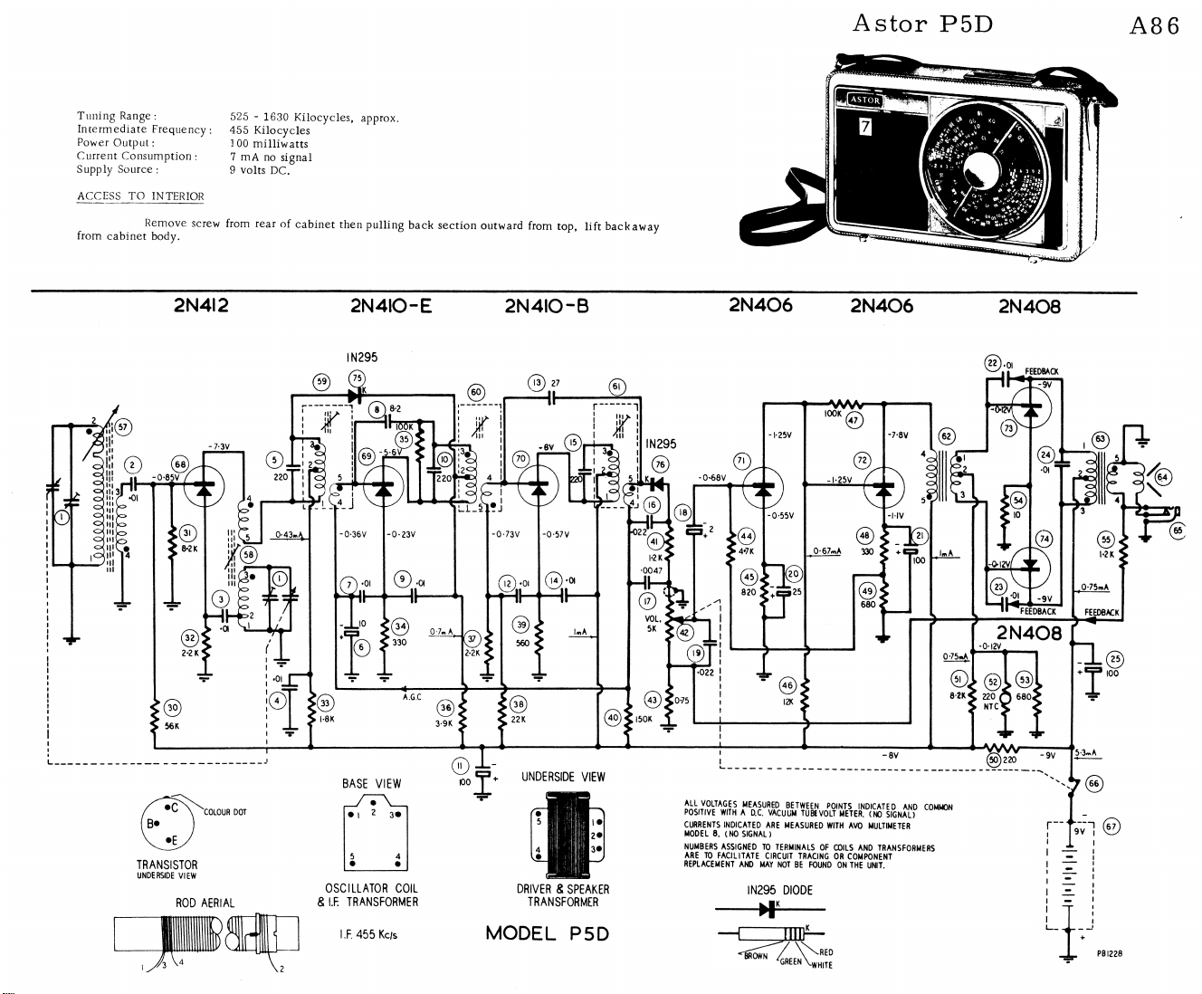
Tuning Range:
Intermediate Frequency:
Power Outp ut:
Current Consumption :
Supply Source :
ACCESS TO INTERIOR
from cabinet body.
Remove screw from rear o f cabinet then pulling back section outward from top, lift back away
2N4I2
525 - 1630 Kilocycles, approx.
455 Kilocyc les
1 00 milliw atts
7 mA no signal
9 volts DC.
2N4IO-E 2N4IO-B
2N406
2N406
2N4Q8
©
TRANS IS TOR
UNDERSIDE VIEW
ROD AERIAL
I
COLOUR DOT
• 1 2 3 ·
5 4
• ·
OS CILLATOR COIL
& I.F. TRANS FORMER
I.F. 455 Kc/s
r n H n
4 Η · !· 3*
,· nuniiiii ,
DRIVER & SPEAKER
TRANSFORMER
MODEL P5D
CURRENTS INDICATED ARE MEASURED WITH AVO MULTIMETER
MODEL 8. (NO SIGNAL)
NUMBERS ASSIGNED TO TERMINALS OF COILS AND TRANSFORMERS
ARE TO FACILITATE CIRCUIT TRACING OR COMPONENT
REPLACEMENT AND MAY NOT BE FOUND ON THE UNIT.
IN295 DIODE
—HP
---
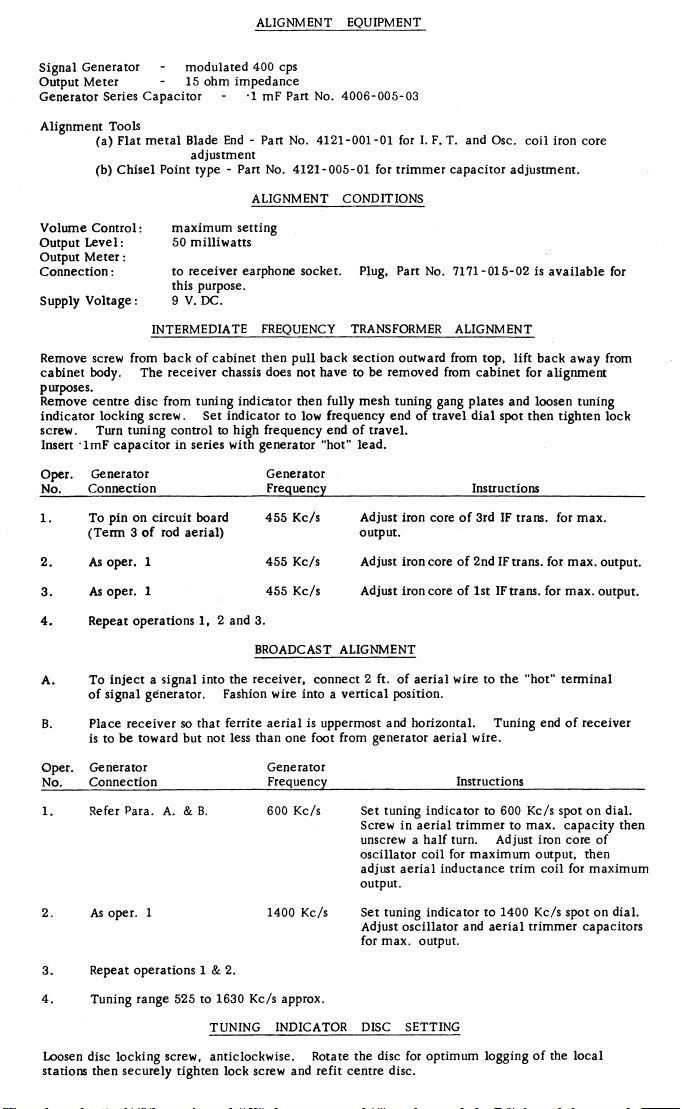
ALIGNMENT EQUIPMENT
Signal Generator - modulated 400 cps
Out put Meter - 15 ohm impedance
Generator Series Capac itor - ·1 mF Part No. 4006-005-03
Al ignment Tool s
(a ) Fla t m etal Blade End - Part No. 4121 -001-01 for I. F. T. and Osc. c oil iron co re
(b) Chisel Point type - Part No. 412 1-005-01 for t rimmer capacitor adjustment.
Volume Control:
Output Level:
Out put M eter:
C o nne cti o n :
Supply Vo lta g e:
Remove screw from back of cabinet then pull back se ctio n outwar d from top, lift back away from
cabinet body. The receiv er chassis does not have to be removed from cabinet for alignment
purposes.
Remove centre disc fro m tuning indicator then fully mesh tun ing gang plates and loo sen tuning
indicator locking screw . Set indicator to low frequency end o f travel dial sp ot then tighten loc k
scre w. Tur n tuning control to high frequency end of travel .
Insert lm F capacitor in series with generator "hot" lead.
Oper. Genera tor
No. Connection
To pin on c ircuit board
(T erm 3 o f rod aerial)
As oper. 1 455 Kc/s
2.
As oper. 1 455 Kc/s
3.
Rep eat operations 1, 2 and 3.
4.
To inject a signal into the receiver, connect 2 ft. of aeri al wire to th e "hot" ter m inal
A.
of si gnal generat or. Fashion wire into a vertical position.
Place receiver so that ferrite aeri al is uppermost and hori zontal. Tuni ng end o f receiver
is to be toward but not less than one foot from gene rator aerial wire.
Genera tor
Oper.
Connection
No.
Refer Para. A. & B.
As oper. 1
Repeat ope rations 1 & 2.
Tun ing range 525 to 1630 Kc/s approx.
Loosen disc locking screw, anticlockwise. Rotate the disc for optimum logging of the local
sta tions the n sec urel y tighten lock screw and refit centre disc .
adjustment
ALIGNMENT CONDITIONS
m axim um setting
50 milliwat ts
to receiver earphone socket. Plug, Part No. 7171-01 5-02 is avai lable for
this purpose.
9 V. DC.
INTERMEDIATE FREQUENCY TRANSFORMER ALIGNMENT
Generator
Frequency Instr uctions
455 Kc/s
BROADCAST ALIGNMENT
Generator
Freq uency Instruction s
600 Kc/s Set tuning indicat or to 600 Kc/s spot on dial.
1400 Kc/s Set tuning indica tor to 1400 Kc/s spot o n dial.
TUNING INDICATOR DISC SETTING
Adju st iron core o f 3rd IF trans. for max.
output.
Adjust ir on core of 2n d IF trans. for max. output.
Adjust iron core of 1st IF trans. for max. output.
Screw in aerial trimmer to max. capacity then
unscrew a h alf turn. Adjust iron core o f
oscillator coil for maxim um output , then
adj ust a erial inductance trim coil for maxi m um
ou tput.
Adjust oscillator and a erial trim mer capacitors
for ma x. output.
 Loading...