

Page 1
R ad io C o rp o r a t io n P ty. Ltd. bulletin: R-12
DIVISIO N Of ELECTRONIC INDUSTRIES LTD.
126- 130 G RANT STREET, SOUTH MELBOURNE, S.C.4.
TECH N ICAL BULLETIN
SUBJECT-
INSTALLATION INSTRUCTIONS
for fitting
MODEL "CR" 6 VALVE 6 VOLT CAR RADIO INTO THE 1949-50 PONTIAC CAR
Antenna
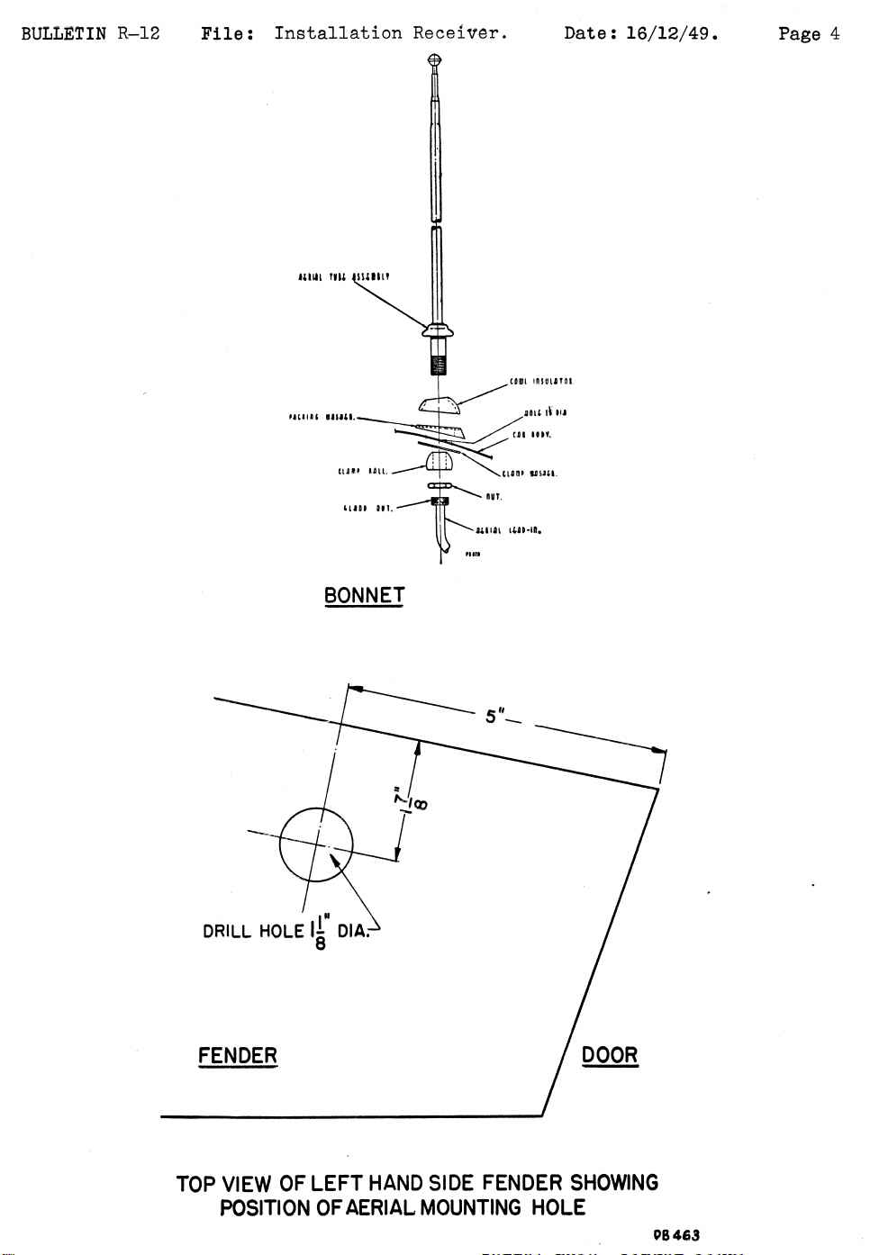
The antenna used is a four section telescopic whip type which is
mounted on the car fender (mudguard) in the position shown in the diagram.
1· Centre punch the mark and drill a 1 1-8 in. dia. hole. Clean off all
paint, grease and burrs for approx. { in. on the underside of the hole
with a sharp-edged tool or emery paper to ensure proper electrical earthing
of the clamp washer.
2. Remove the lead-in, lock nut, clamp ball and clamp washer from the
antenna base. Insert the antenna base into the top of the hole. Hold the
antenna vertical and turn the formed rubber washer on the antenna base so
that it fits the form of the fender.
3. On the underside of the fender, reassemble the clamp washer, clamp ball
and lock nut to the antenna base. Tighten the lock nut securely, making
sure the antenna remains vertical, and the formed rubber washer follows
the form of the fender.
4. Reassemble the lead-in cable to the base of the antenna, making sure the
♦ knurled gland nut on the lead-in is securely tightened.
Fil e: Installation
Receiver
Date: 16/12/49
Pag e: 1
Assembly of Sub Unit to Receiver Case
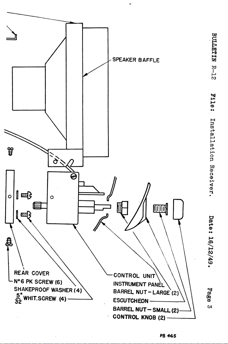
1. Remove knobs, small barrel nuts, escutcheon and large barrel nuts from
sub unit spindles.
2. Remove rear cover of sub unit by unscrewing the six self tapping screws
around the outer edges.
3. Insert 7 pin plug lead and shielded lead from receiver through large hole in
sub unit rear cover, then fasten the rear cover to front of receiver
case with four i in. x 5/32 in. dia. whit, screws and S/P. washers.
4. Insert a small screwdriver through hole in receiver can into rubber
moulding on condenser gang shaft and turn fully clockwise.
5. Connect lug on end of shielded A-f- lead from receiver under head of
screw in corner of 7 pin socket on sub unit. Fit 7 pin plug on to 7 pin
socket.
6. With the pointer in extreme clockwise position insert splined end of
tuning spindle into rubber moulding on condenser gang.
7. Re-assemble sub unit to its rear cover on receiver with the six self
tapping screws.
Installation of Receiver and Speaker Into Car
1. Viewing the car from the front, drill from the engine side of the
firewall or bulkhead an 11/32 in. dia. hole 1 in. below centre of right
hand horn bottom mount bolt and a i- in. to the left.
2. Remove escutcheon from car instrument panel.
3. Loosen off 5/16 in. nut on rear of set mount bolt-do not remove it
completely.
4. Insert receiver up behind instrument panel-control spindles to protrude
through holes in panel.
5. Clamp unit in position by fitting to control spindles the two large
barrel nuts, finger tight.
Page 2
BULLETI N
L—12 File: Install ation Receiver. Date: 16/12/49.
Page 4
BONNET
TOP VIEW OF LEFT HAND SIDE FENDER SHOWING
POSITION OF AERIAL MOUN TING HOLE
PB 463
Page 3
BU LLETIN R—12
Installation of Receiver and Speaker into Car— Continued.
6. Fit speaker baffle in position behind speaker grille on instrument panel,
the slots in the lugs on speaker baffle ends fit over the two spacers
either end of control unit.
7. Fit receiver rear support stay in position by sliding slotted section
over receiver rear mount bolt (refer diagram) and the tongue on the
opposite end fits into top fold of baffle.
8. Securely tighten nut on receiver rear mount bolt and large barrel nuts
on control spindles.
9. Insert 5/16 in. bolt through bottom hole in rear support stay and
firewall and securely tighten.
10. Fit escutcheon, small barrel nuts and tighten securely; fit push-on
knobs.
11. Connect speaker lead plug to receiver speaker socket. Connect antenna
lead-in to receiver lead-in socket. Connect A + lead from receiver sub
unit to battery side of ammeter.
Interference Elimination
1. No spark plug suppressors are required.
2. Distributor Suppressor:-Remove the high tension lead from the distributor
cap and into its place fit a plug-in type suppressor. On to the HT.
lead fit the rubber cap supplied, connect HT. lead into outer end of
suppressor and slip rubber cap over the connection.
3. Mount a .5 MFD. metal clad by-pass condenser on the generator under the
head of the screw provided for this purpose. Connect the lead from the
condenser to the armature terminal, not the field terminal-make the lead
as short as possible.
4. Mount a .5 MFD. metal clad by-pass condenser under the head of the bolt
fastening the coil mount clip. Connect the lead from the condenser to
the battery terminal of the co i l - m a k e the lead as short as possible.
The nuts and mounting positions of the by-pass condensers must be
entirely free of grease, insulating varnish or paint to ensure a proper
electrical contact.
Parts List
Antenna
Antenna Lead-in
Tone Control
Volume Control
Speaker
Speaker Plug
Dist. Suppressor
Rubber Cap
Fuse
Dial Pointer
Control Knob
Knob Spring
7 Pin Socket Assy.
7 Pin Plug Assy.
Barrel Nut
Barrel Nut
Escutcheon
No. 6 PK. Screw
Dial Reading
Dial Lamp
Thumb Wheel
Rear Mount Bolt
Rear Mount Nut
By Pass Cond.
Pile: In stallation Receiver
Antenna only, less lead-in, fully extended
49", fully retracted 15"
48" overall length
100K. ohm.
.5 megohm
6" x 9" oval type (speaker only with 2 only
24" leads, less shielding braid and plug)
2 pin
Plug-in type, 6 volt
For fitting over suppressor connection
15 amp.
On remote control head
On receiver lead
Small type
Large type
6-8V. 0.3A. min. bay. base G3^ bulb
Bracket to firewall
Bracket to firewall
.5MFD . 200V. DCW. Metal clad
Date 16/12/49. Page 2
Part No.
M223
M224
PR678
PR679
K158
336/30C
PR221
14/140
PM219
A104/325-2
4/310-2
86/71
A104/323
A104/58-1
9/325
13/325
17/325-1
35/560-2
14/665-3
M127
3/306-1
48/560-18
3/478-14
PC545
Page 4
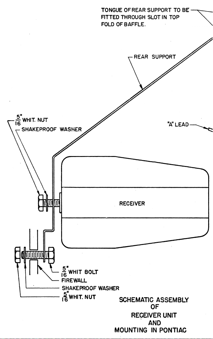
TONGUE OF REAR SUPPORT TO BE
FITTED THROUGH SLOT IN TOP
FOLD OF BAFFLE.
OF
RECEIVER U NIT
AND
MO UNT I NG IN PONT IAC
Page 5
C ONTROL KN OB (2)
 Loading...