

Page 1
R adio C o rporation Pty. Ltd . bulletin: r-14.
d i v i sio n o f e l e c t r o n i c i n d u s tri e s l t d . File: Installation
126-130 GRANT STREET, SOUTH MELBOURNE, S.C.4.
Date : 20/4/50.
TECHNIC A L BULLETIN Page: i.
SUBJECT- INSTALLATION INSTRUCTIONS
for fitting
MODEL “CS” 12 VOLT 6 VALVE CAR RADIO INTO THE AUSTIN A90 CAR
ANTENNA.
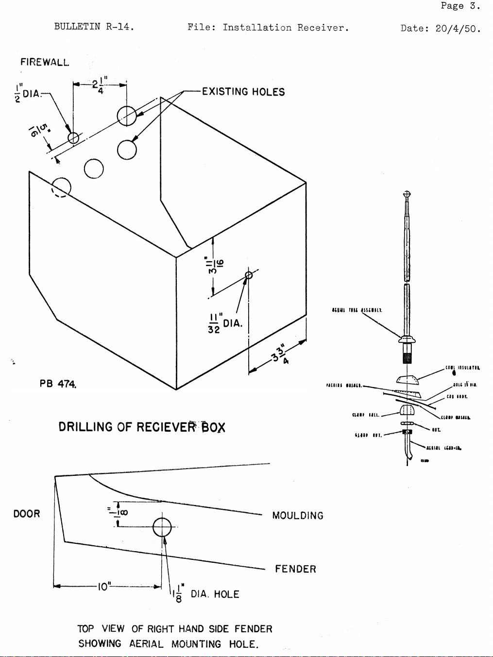
mounted on the car fender (mudguard) on the driving side in the position
shown in the diagram. Clean off all paint, duco or grease for inch around
hole on underside of fender.
ASSEMBLY OP SUB-UNIT TO FRONT OP RECEIVER CASE.
The antenna used is a four section telescopic whip type which is
1. Insert shielded lead from receiver through large hole in sub unit and
fasten the lug on end of this lead under the head of the screw in the
corner of the 7-pin socket.
2. Insert 7-pin plug on lead from receiver through large hole in sub unit
and fit on to 7-pin socket.
3. Mount sub-unit on to front of receiver can with the 5/32 in. dia.
screws supplied in accessory package. Fit plug lead cover plate to
side of sub-unit with a 5/32 in. dia. screw and one self-tapping screw
supplied in accessory package.
INSTALLATION OF SPEAKER.
1. Remove trim panel from driving side (panel has speaker grille mounted
in position).
2. Mark and cut out slot in body panel to correspond to the lead slot in
the speaker plate.
3. Mount the speaker plate into the hole in the body panel using four
No. 2BA screws and S/P washers supplied in accessory package.
4. Refit trim panel, running the speaker lead up between the body and
trim panels.
INSTALLATION OF RECEIVER INTO CAR.
1. Drill hole in firewall and hole in front face of receiver box as shown
in diagram. Clean off all paint, grease or duco for -J- inch around the
holes to provide a good electrical contact.
2. Remove the six control knobs from along the bottom edge of the in
strument panel.
3. Remove the instrument cluster sub-panel from behind the instrument
panel by unscrewing the four screws in the corners of the centre
section of the panel.
4. Remove the expanded metal grille from the centre of the panel. This
is accomplished by pressing the grille in through the opening in the
panel, care must be exercised not to strip the speednuts off the
moulded excutcheon.
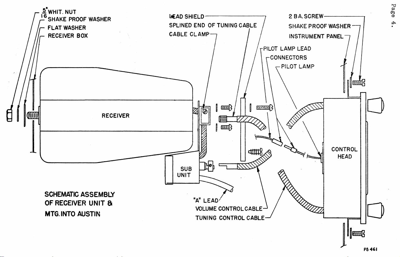
5. Assemble control head to sub-panel by inserting control cables through
holes in firewall. Mount control head to panel with two No. 2BA
screws supplied in accessory package.
6. Screw sub-panel back into position and refit control knobs.
7. Insert a small screwdriver into hole in receiver case and into the
rubber moulding on the condenser gang shaft and then turn screw driver
fully clockwise.
Page 2
8. Connect speaker lead and antenna lead-in to their respective sockets
on receiver case.
9. Mount receiver in position in receiver box and securely clamp in
position.
10. Turn control head tuning knob fully clockwise until pointer reaches
max. travel of the dial, then insert splined end of tuning control
cable through hole in receiver can into rubber moulding on condenser
gang shaft. Clamp cable under small clip on sub-unit.
11. Insert end of volume control cable into collar on volume control shaft
and securely tighten grub screws.
12. Connect A+ lead from control head to “spare” terminal post on junction
block on firewall.
INTERFERENCE ELIMINATION
No spark plug suppressors are required.
Distributor Suppressor: Insert a distributor suppressor, part No.
PR314, in the high tension lead from the coil a few inches from where the
lead enters the distributor. Make sure the'lead is fitted well into the
suppressor and that good contact is made. Securely bind the lead at both
ends of the suppressor with adhesive tape.
Ignition Coil Condenser: Install a metal clad .5 MFD. by-pass con
denser part No. PC545 on the battery terminal of the ignition coil keeping
the lead as short as possible. The condenser is mounted under the bolt
which fastens the ignition coil mount strap. The other side of the con
denser is internally connected to the condenser case which forms the other
contact to the car when mounted. Generator Condenser: Install a .5 MFD.
metal clad condenser part No. PC545 on the generator. Connect the lead from
the condenser to the armature terminal not the field terminal, make the lead
as short as possible. The condenser is mounted on the generator mount bolt
nearest to the armature terminal.
NOTE: The nuts and mounting positions of the by-pass condensers must be
entirely free of paint, grease or duco varnish to ensure a good electrical
contact.
Parts List
Antenna
Antenna Lead-in
Volume Control
Speaker
Speaker Plug
Dist. Suppressor
By-pass Cond.
Fuse
Pointer Assy.
Control Knob
Knob Spring
7 Pin Socket Assy.
7 Pin Plug Assy.
Dial Reading
Dial Lamp
Excutcheon
Rear Mount Nut
2BA Screw
Control Cable Assy.
Control Cable Assy.
Cable Clamp
Connector
Connector
Antenna Accessory Package A105/671 contains rubber tube 35/671, sealing
washer 34/671 and mount washer 33/671; these parts are for water
proofing lead-in connection to base of antenna on underside of fender.
Antenna only, less lead-in, fully extended
49”, fully retracted 1 5”
48” overall length
.5 megohm
5” round type, less leads, shielding braid,
nylex covering and plug
2 pin
Screw type, 12 volt
.5M FD . 200V. DCW. Metal clad
15 amp.
On sub unit
On receiver lead
6-8V. 0.3A. min. bay. base G3J bulb
On receiver case rear mount screw
Mounts control head
Volume
Tuning
Male, dial lamp lead
Female, dial lamp lead
Part No.
M2 2 3
M2 2 4
PR661
K124
336/30C
PR314
PC545
PM219
A103/323
15/306-1
86/71
A104/323
104/58-1
14/665-1
M127
1/324
3/478-14
2/415
A105/324-1
A104/324-1
45/73-1
32/304
39/305
Page 3
Page 3.
BULLETIN R-14 .
FIR EW ALL
Pile: Installation Receiver.
Date: 20/4/50.
D OOR
DRILLING OF RECIEVEft BOX
TOP VIEW OF RIGHT HAN D SI DE FEND ER
SHOWING AERIA L MOU NTI NG HOLE.
Page 4
Page 4.
£ WH I T. NUT
SHAKE P RO OF WASHER
FLAT WASHER
t*AD SH I ELD·
2 BA.SCREW
S HAKE PROO F WASHER
IN STRUME NT PANEL
PIL OT LAMP LEAD
C ONNECTORS
PI LOT LAMP
SCHEMATIC ASSEMBLY
OF RECEIVER UNIT ft
MTG.INTO AUSTIN
"A" LEAD'
VOLUME CONT ROL CABLE-
TUNIN G CONTROL C AB LE-
Ρ Θ 461
 Loading...