

Astor P14N Service Manual
A79
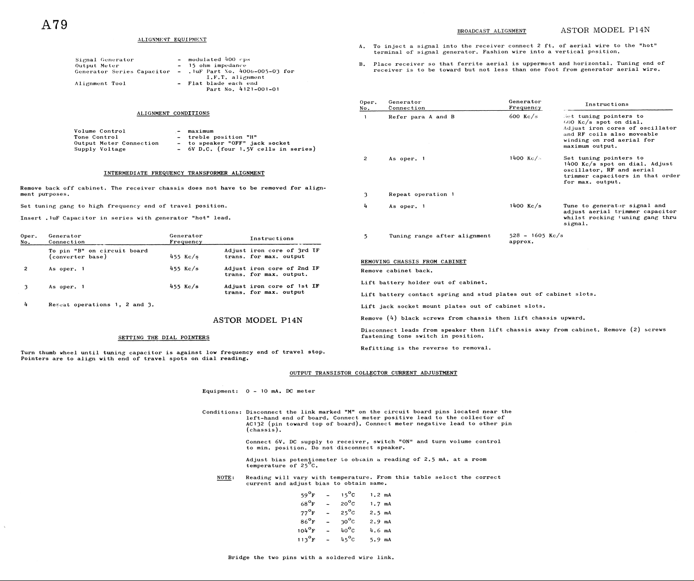
ALIGNMENT EQUIPMENT
Signal Generator
Output Meter
Generator Series Capacitor
Alignment Tool
ALIGN ME NT CONDITION S
Volume Con t ro l
Tone Contr ol
Output Met e r Conn ec t io n
Supply Volta ge
INTERM E DI A T E FREQU E N C Y TRANSF OR ME R ALI GN M E NT
Remove back off cabinet· The rece iv er ch assis does not have to be re moved for a l i g n
ment purposes.
Set tuning gang to hi g h frequ en cy end of travel position.
Insert . luF Capac it o r in series wit h gene r ato r "hot 11 lead.
Oper. Generato r
No.
_____
Connection
To pin "B" on c ir cu it board
(converter base)
As oper. 1
As oper. 1
Ren^at operat io ns 1, 2 and 3·
SETTING TH E D IAL P OIN TE R S
Turn thumb wheel until tuni n g capa ci to r is agai nst low fr e qu en cy end of travel stop.
Pointers are to a lign with en d of travel spots on dial reading.
modulated 400 rps
15 ohrn impedance
. 1 uF Part \o. 400G-005-03 for
I. F. T. al igrimont
Flat blade each end
Part No. 4121-001-01
maximum
treble posi tio n "H ”
to speaker "OFF" jack socket
6V D.C. (four 1.5V cells in series)
Gener ato r
Frequen cy
455 Kc/s trans. for max. output
455 Kc/s Adjust iron core of 2nd IF
455 Kc/s Adjust iron core of 1st IF
Instrue tions
Adjust iron core of 3rd IF
trans. for max. output.
trans. for max. output
ASTOR MODEL P14 N
OUTPUT T R A NSI ST O R COLLE CTO R CURREN T ADJU ST M E NT
BROADC AS T ALIGNMEN T AS T O R M O D E L P 1 4N
A. To inject a signal into the rec ei ve r connect 2 ft. of aerial wire to the "hot"
terminal of signal generator. Fashion wire into a vert ic al position.
B. Place receiver so that ferri te aer ial is up perm ost and horizontal. Tuni ng end of
receiver is to be toward but not less than one foot from generator aerial wire.
Oper. Genera tor
No .
_____
Connec tio n
Refer para A and B
2 As oper. 1
3 Repeat operat io n 1
4 As oper. 1
Tuning range after alignment
REMOVI NG CHASSIS FROM CABINE T
Remove cabinet back.
Lift b at tery holde r out of cabinet.
Lift ba tter y contact spring and stud plates out of cabinet slots.
Lift jack socket mount plates out of cabinet slots.
Remove (4) black screws from chassis then lift chassis upward.
Disconnect leads fro m speaker then lift chassis away from cabinet. Remove (2) screws
fastening tone switch in position.
Refitt i n g is the reverse to removal.
Generator
Frequency
600 Kc/s
1 400 Kc/:·
1U00 Kc/s
528 - 1605 Kc/s
approx.
Instructio ns
Set tuning pointers to
M)0 Kc/s spot on dial.
Adjust iron cores of o sc i lla t or
and RF coils also movea bl e
winding on rod aerial for
maximum output.
Set tuning point er s to
1400 Kc/s spot on dial. Ad ju st
oscillator, RF and aerial
trimmer ca pac it ors in that order
for max. output.
Tune to ge ne rat or signal and
adjust aerial tr immer ca pa ci tor
whilst rockin g luning g ang thru
signal.
Equipment: 0-10 mA. DC me ter
Conditions: Disconne ct the link mar ke d !tM" on the cir cuit bo ard pins lo cat ed near the
left-hand end of board. Connect me ter positive lead to the collec to r of
AC 132 (pin toward top of board). C onnec t mete r negat iv e lead to ot her pin
(chassi s ).
Connect 6V. DC supply to receiver, switch "ON" and turn volume control
to min. position. Do not disco nn ect speaker.
Adjust bias poten ti om ete r to obcain a readi ng of 2.5 niA. at a roo m
temperature of 25 C.
NO TE: Readin g will v ary with temperature. From this table select the correct
current and adju st bias to obtain same.
1 ,
-
59°F
68°F
77°F
86°F
10**°F
1 13°F
Bridge the two pins wi t h a sol dered wire link.
15°C
-
25°C
-
3 0 °c
-
-
ko°c
-
k5°C
,2 mA
0
1 .
O
0
,7 mA
2.
.5 mA
2.
► 9 mA
k.► 6 mA
» 9 mA
5.

A79
ASTOR MODEL P1 4 N
_ „ .
-
Λ r\
M U
l ) v
- +
Λ
-
j j
® +
CIRCUIT BOAR D PRINTED WIRING SIDE MODEL PI4N.
Λ
-
+
~
P 0 $ I I I , t f c - ™ SWI TCH
+
dr’ n .
Otk
ch ' d. APP.
tx
(U 3)
DATE
%\2-65
 Loading...