

Astor LT-10 User Manual
e
r.IJ
~
~
C1
=
......
0
0
0
m
C1)
n
....
a
~
n
-.
~
C1)
0
Q.
-
0
-
.
e.
m-
~

e.
m-
~
Catalogue
1 Application
2 Nomenclature
I
3 Display and display mark
I
I
4 Operating keyboard and operating key
5 Preparative before measurement
5.1
Leveling the instrument
5.2
Power
switch
on
5.3
Battery
power
display
5.4
Change
the battery
6 Angle measurement
6.1
Measuring a
HAR
and vertical angle
6.2
Swi
tching
hor
izontal
angle
HAR / HAL
6.3
Setting
a
hori zontal
angle
6.4
Repetition angle measurement
6.5
Measuring a percent
of
grade (
Slope
measurement)
7
Recording and outputting data
7.1
RS-232 serial communication interface
7.2 Recording measurement data
8 Memory mode
9
Function setting
9.1
Function setting
9.2
Function setting method
3
9.3
Time
setting
14.Error displays
10
Vertical angle 0 error and collimation error and tilt
angle compensator 0 error
11
Other function
11.1
Measuring
distance
11.2
Tilt
correction
function
11.3
Illuminate
and
the timing close
12 Check and adjustment
12.1
Check
and
adjust plate level
12.2
Check
and
adjust circular level
12.3
Check
and
adjust
vertical cross-hair
12.4
Collimation
of
the instrument sight line
12.5
Check
and
adjust optical
plummet
13
Tribrach
14
Error display
15
Specifications
16
Accessories and equipment
EOl
E02
E03
E04 There's abnormality in internal memory system.
E05 Reserved for adjustment
E06 There's abnormality
E07
E08
4
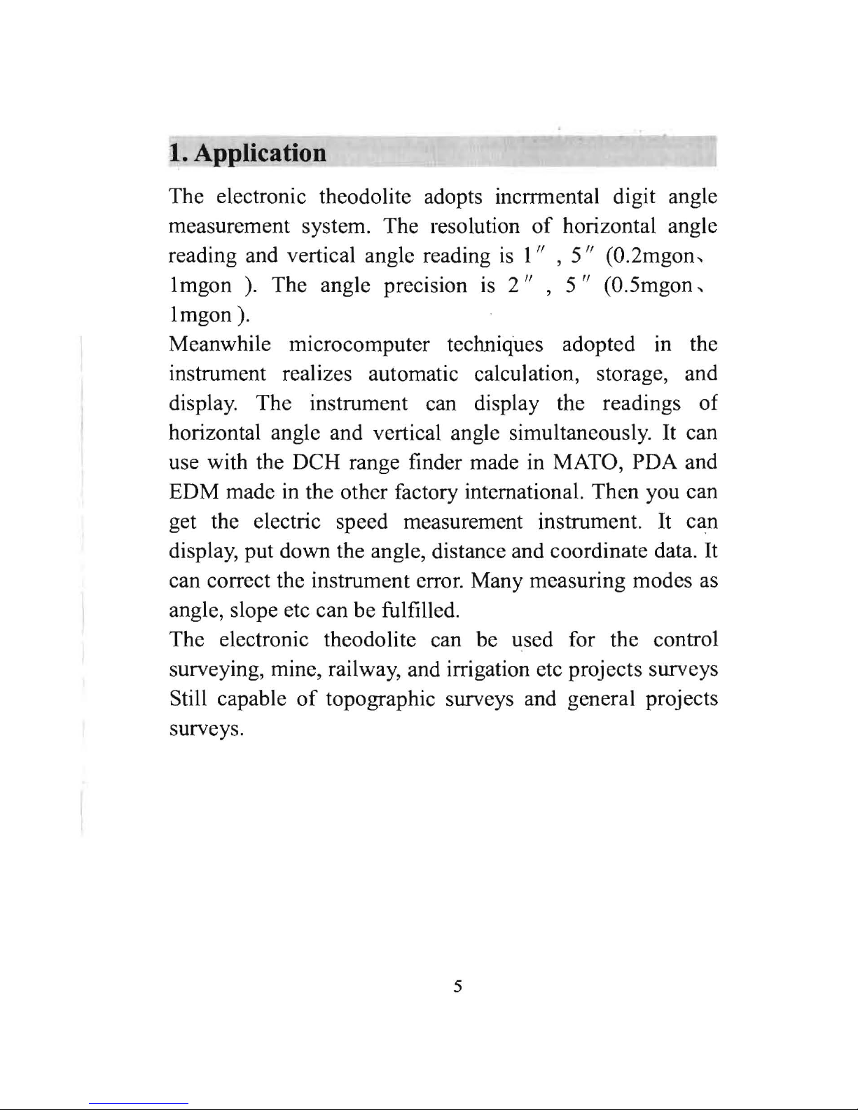
1. Application
The electronic theodolite adopts incrrmental digit angle
measurement system. The resolution
of
horizontal angle
reading and vertical angle reading
is
I" , 5"
(0.2mgon,
lmgon
).
The angle precision
is
2"
,
5"
(0.5mgon,
lmgon
).
Meanwhile microcomputer techniques adopted
in
the
instrument realizes automatic calculation, storage, and
display. The instrument can display the readings of
horizontal angle and vertical angle simultaneously.
It
can
use with the DCH range finder made in MATO, PDA and
EDM made
in
the other factory international. Then you can
get the electric speed measurement instrument. It can
display, put down the angle, distance and coordinate data.
It
can correct the instrument error. Many measuring modes as
angle, slope etc can be fulfilled.
The electronic theodolite can be used for the control
surveying, mine, railway, and irrigation etc projects surveys
Still capable
of
topographic surveys and general projects
surveys.
5
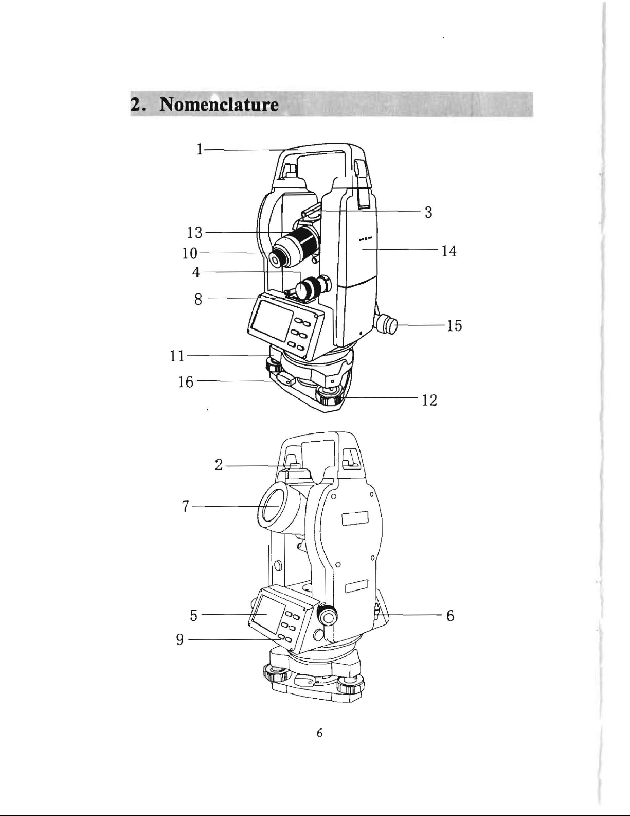
2. Nomenclature
1
3
13
\~'\W
II
--I
r.:::s:,
l'
II/I~II
10
14
4
8
II
l~IJJ
A--,.
15
https://manualmachine.com//
ll.V
~
11
16
'-............. ....J...
: ....
JJDI
12
2 //Lc'Jl
7
1/1
II
5
,W
r/\\
6
9
::,,<°
1
Note:
To
side and tighten adjustment screw
according to the loosened number. (Loosen: counter
clock-wise. Tighten: clock-wise. Rotate screws as little
as possible.)
6
I
(
1)
carrying handle
(2)
handle screw
(3)
sighting collimator
(4)
vertical tangent screw and motion clamp
(5)
operating key
(6)
RS-232C communication interface
(7)
objective lens
(8)
plate level
(9)
display window
(l0)
eyepiece
(11) base plate (12) foot screw(13) focusing knob (l4)battery
(15)horizontal tangent screw and motion clamp
(16) base locking lever
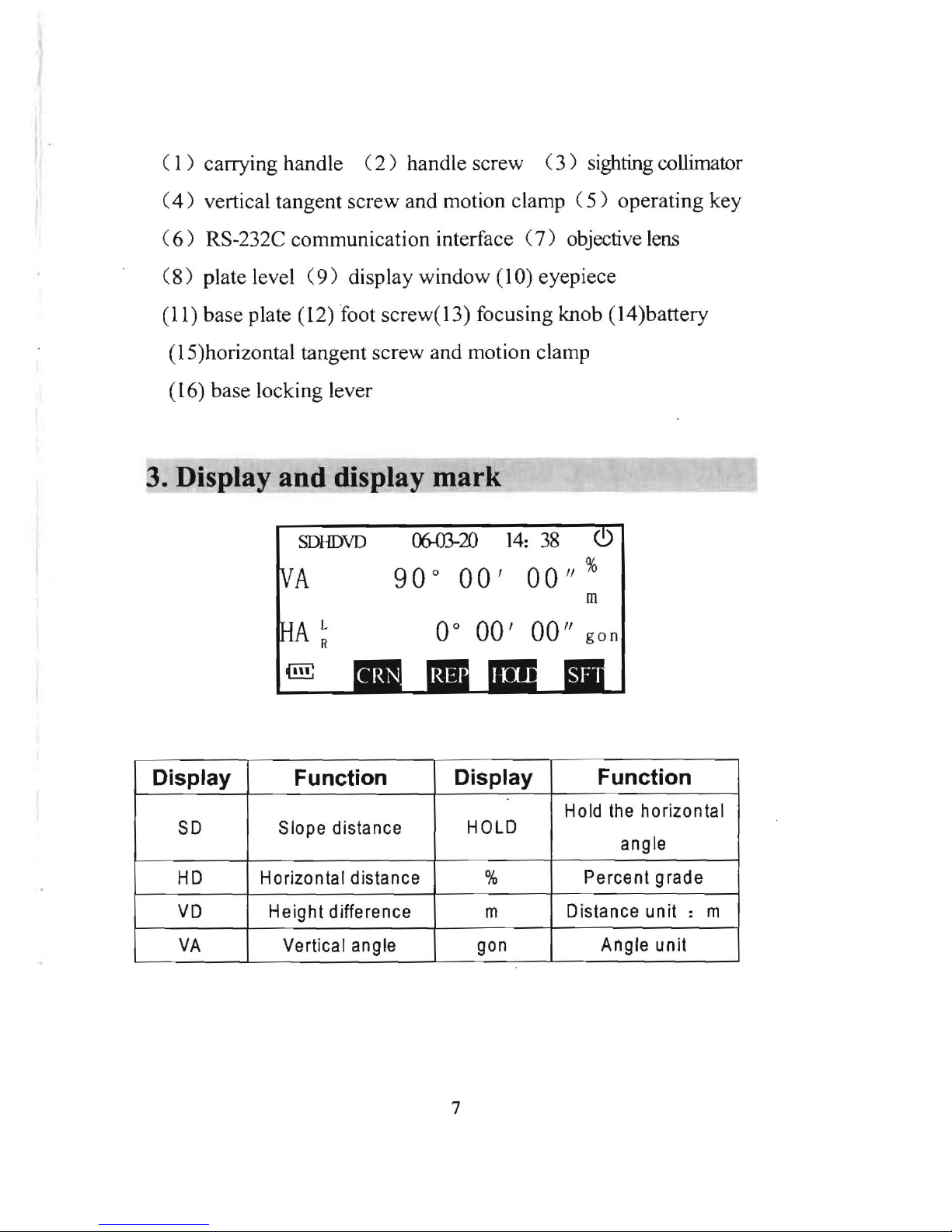
3. Display and display mark
SDHDVD
~20
14:
38
90 0 00'
00"
%
m
L
00 00'
00"
gon
(ill!
Display Function
Display Function
Hold
the
horizontal
SO
Slope distance
HOLD
angle
HD
Horizontal distance %
Percent grade
VD
Height difference
m Distance
unit:
m
VA
Vertical angle
gon
Angle unit
--
7
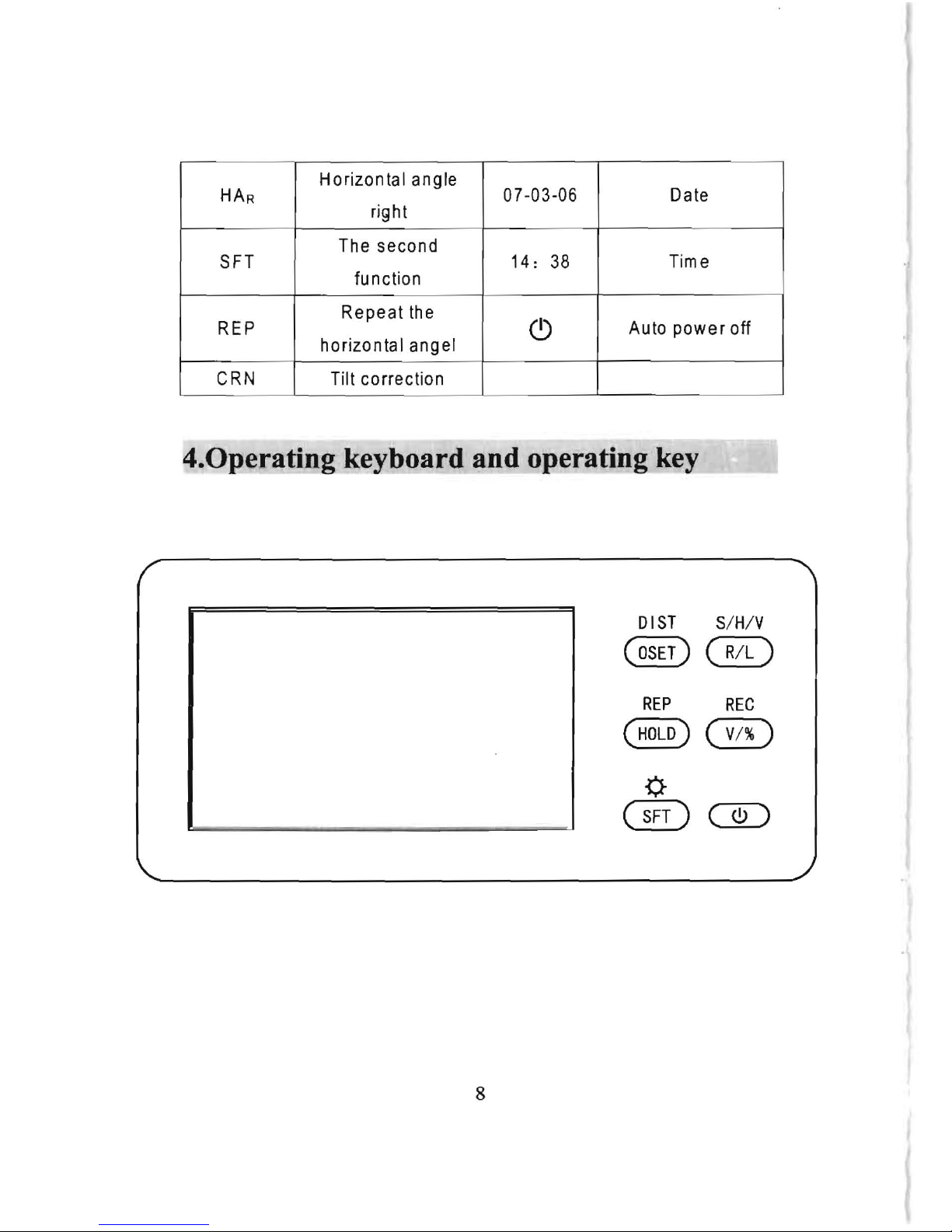
HAR
Horizontal angle
right
07
-03-06 Date
I
SFT
The second
function
14:
38
Time
REP
Repeat
the
horizontal angel
(!)
Auto power off
eRN Tilt correction
- -
4.0perating keyboard and operating key
OIST S/ H/V
@@D
REP
REC
@)G0)
{)
@~
8
Adjustment
To
move vertical cross-hair, first loosen the capstan adjustment
screw, then screw the capstan adjustment screws on the other side
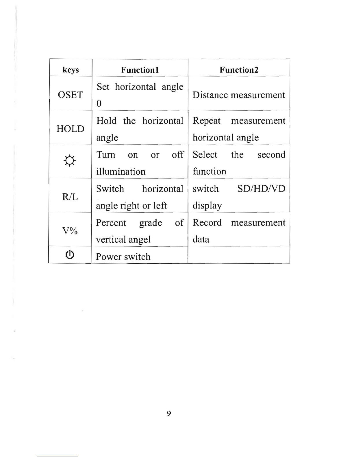
keys
Functionl Function2
OSET
Set horizontal angle
Distance measurement
0
HOLD
Hold the horizontal Repeat measurement
angle
horizontal angle
-0-
Tum
on
or
off
Select the
second
illumination function
RlL
Switch horizontal
switch
SD/HDND
angle right or left
display
V%
(!)
Percent grade
of
Record
measurement
vertical angel
data
Power switch
--_
.
_-
'-------
- -
--
- -
~
-
9
5'\
Preparative before measurement
5.1 Level the instrument
Level and center the instrument correctly to insure the
best perfonnance.
C!)
Place the tripod
First,
put
the tripod leg in the proper position and tighten
the locking screws.
@Attaching the instrument to the tripod head
Place the instrument carefully on the tripod head, and
move the instrument slowly by loosening adjusting
screw. Align the plumb bob with the point on the ground
When aligned, tighten the adjusting screw.
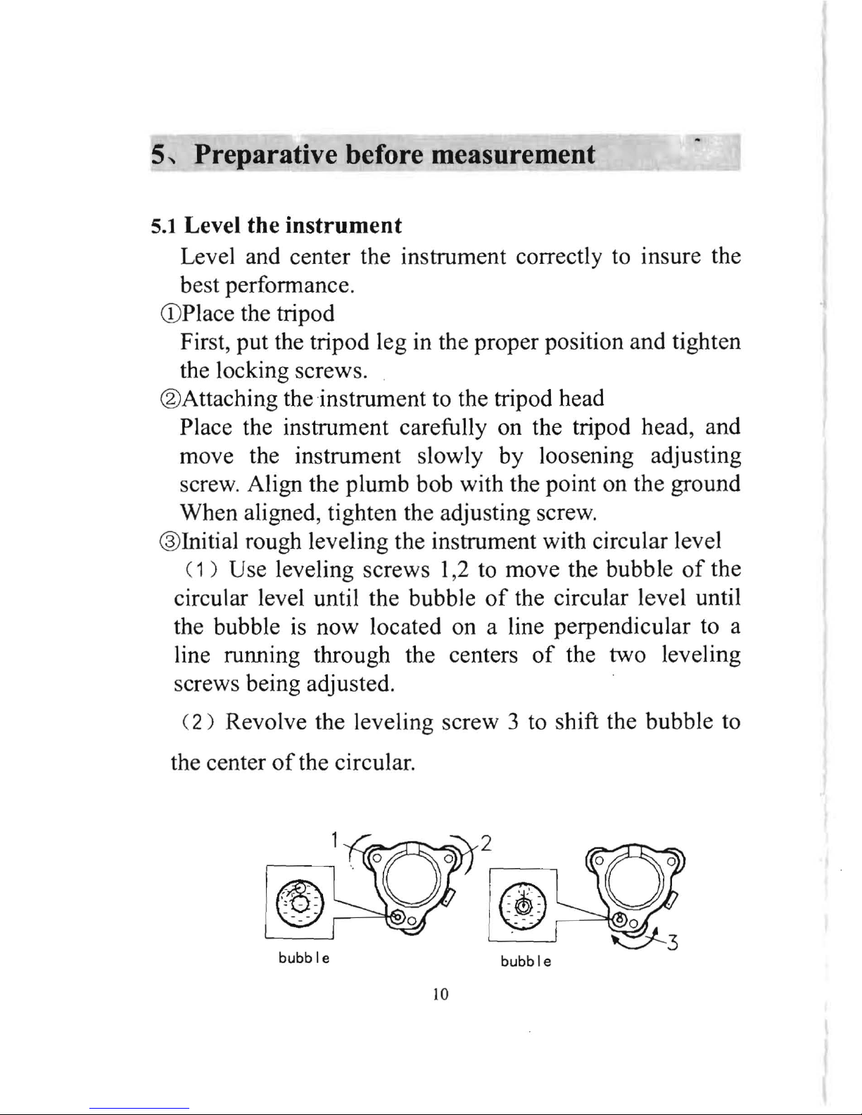
® Initial rough leveling the instrument with circular level
( 1 ) Use leveling screws 1,2 to move the bubble
of
the
circular level until the bubble
of
the circular level until
the bubble is now located on a line perpendicular to a
line running through the centers
of
the two leveling
screws being adjusted.
( 2 ) Revolve the leveling screw 3 to shift the bubble to
the center
of
the circular.
2
r---
0 0
I
~\-o
.
~
~
bubble
~
-=-
bubble
10
Adjustment
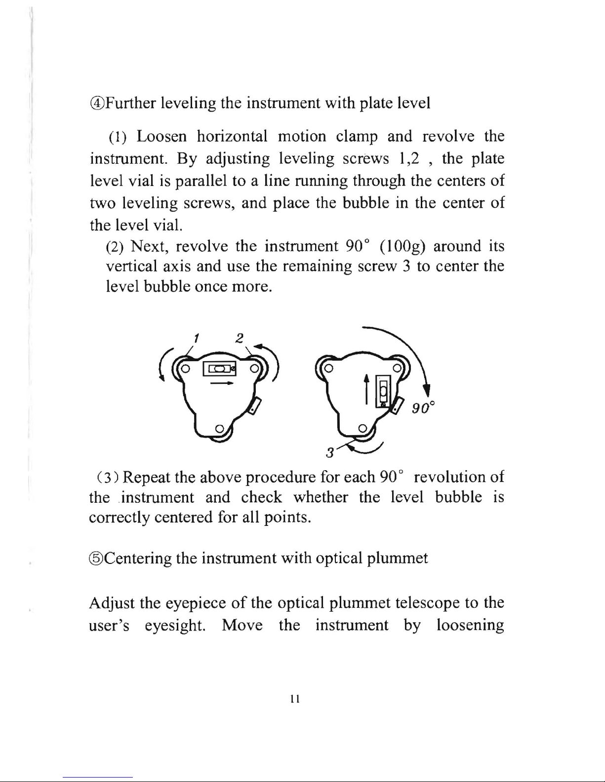
@Further leveling the instrument with plate level
(1) Loosen horizontal motion clamp and revolve the
instrument.
By
adjusting leveling screws l,2 , the plate
level vial
is
parallel to a line running through the centers of
two leveling screws, and place the bubble in the center of
the level vial.
(2) Next, revolve the instrument 90° (lOOg) around its
vertical axis and use the remaining screw 3 to center the
level bubble once more.
(3)
Repeat the above procedure for each 90 revolution of a
the .instrument and check whether the level bubble
is
correctly centered for all points.
@Centering the instrument with optical plummet
Adjust the eyepiece
of
the optical plummet telescope to the
user's eyesight. Move the instrument by loosening
II
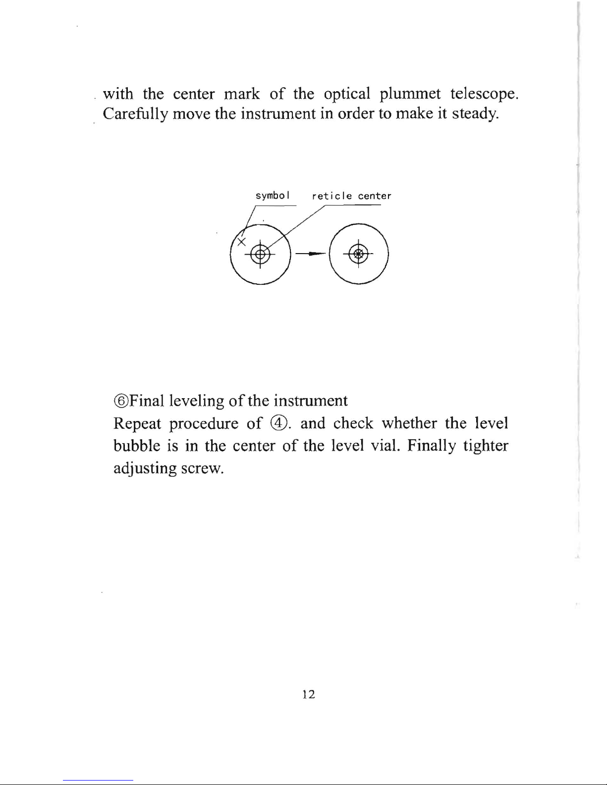
. with the center mark
of
the optical plummet telescope.
. Carefully move the instrument in order to make it steady.
symbol
reticle
center
-0
@Final leveling ofthe instrument
Repeat procedure
of
®.
and check whether the level
bubble is in the center
of
the level vial. Finally tighter
adjusting screw.
12
12.2 Check and adjust vertical cross-hair
Check
the bubble
time, adjustment is not required. Otherwise, proceed with
the following adjustment.
Adjustment
adjusting three capstan adjustment screws on the
bottom surface
adjusting pin.(see diagram)
5.2 Power switch on
CD
Pre
s s
[(!)
1 , all segments
of
the display will light
on. The display shows that vertical angle should be
set to zero.
® Rotate the telescope to set the instrument to a
vertical angle reading
of
o.
@Press
[(!)
lover
2 seconds, it can be power off.
•
In
order to make sure instrument work
continuously, pay attention to battery power
display.
If
battery power is insufficient, replace
battery. Please see 5.3. Battery
power
display.
• For setting the vertical angle at 0, a datum 0 is
provided on the vertical angle scale circumference .
If
the telescope is turned and the sensor passes the
datum 0, angle measurement begins.
13
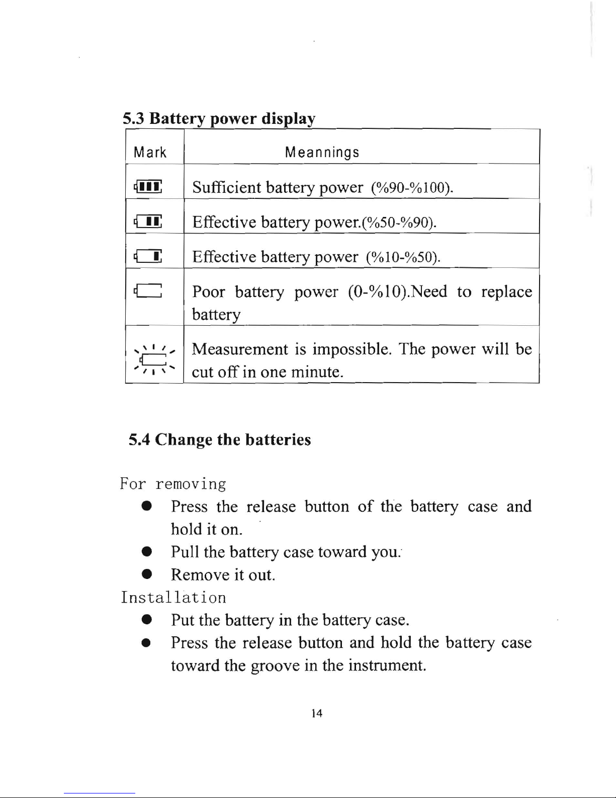
5.3 B
disol
-~-
-
-----
-'"
1.- _
..
--
----r---J
Mark
M eannings
I{ffi;
Sufficient battery power
(%90-% 100).
ill
Effective battery power.(%50-%90).
a
Effective battery power
(%10-%50).
I
C
Poor battery power (O-%lO).Need
to
replace I
battery
....
' I
I"
c=
.,
I I
,""
Measurement
is
impossible . The power will be I
cut
off
in one minute .
--_
. . -- -
5.4
Change
the
batteries
For
removing
• Press the release button
of
the battery case and
hold it on.
• Pull the battery case toward you.
• Remove it out.
Installation
• Put the battery in the battery case.
• Press the release button and hold the battery case
toward the groove in the instrument.
14
12. Check
Pointers
a.
b.
c.
d.
e.
12.1Check
level
Check
a.
-
---
-
-----
6.
Angle measurement
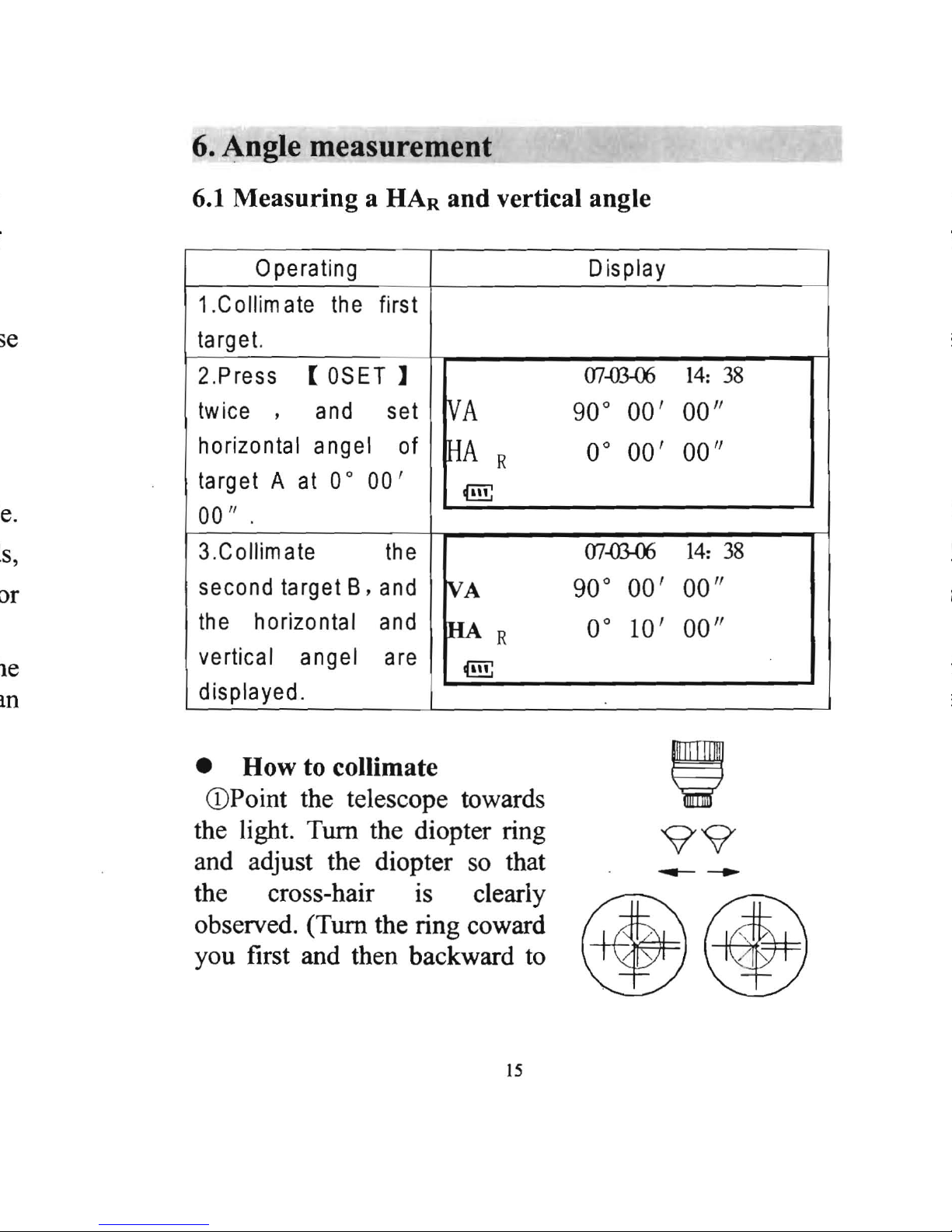
6.1
Measuring
a HAR
and
vertical angle
Operating
1.Collimate
the
first
ta
rg et.
2.Press
[
OSET
]
twice
,
and
set
horizontal angel
of
ta
rg
etA
at
00
00'
001/
.
3.Collimate
the
second target B,
and
the
horizontal
and
vertical angel
are
Ld~s~ayeJ.
___
Display
07-ffi.05
14:
38
~A
90°
00'
00"
~A
R
0°
00'
00"
t@!;
07-D3-05
14:
38
~A
90°
00'
00"
HAR
0°
10'
00"
t@!;
•
How
to collimate
,
(DPoint the telescope towards
the light. Tum the diopter ring
99
and adjust the diopter so that
the cross-hair is clearly
---
observed. (Tum the ring coward
you first and then backward to
~~
15
 Loading...