

Astor A101-310, A101-312 User Manual
R ad io C o r p o r a tio n P ty. L td. bulletin r - 7
DIVISION OF ELECTRONIC INDUSTRIES LTD.
126-130 G R A N T STREET, SOU T H MELBOURNE. S.C.4.
TECHNIC A L BULLETIN
SUBJECT- INSTALLATION INSTRUCTIONS
FOR
NASH AND PACKARD-STUDEBAKER
REMOTE CONTROL UNITS
6 VOLT
File:— Installation
Receive r.
Date: 22/2/47.
Page 1.
CAR_______________________RADIO CORP. PART NO.
Packard — Studebaker A101/310 18g- Ins.
Nash A101/312 18-g- Ins.
These Remote Control Units are for use on the 6 Valve Car Radio Receiver
RADIO CORP. MODEL “J L”
1. Remove and dispose of the cover plate on the instrument panel.
2» Remove the control knobs, chrome plated hexagonal nuts, washers
and bezel from the front of the control head.
3. Insert the control head into the instrument panel from behind and
assemble in place with bezel, nuts and washers. Replace the
control knobs.
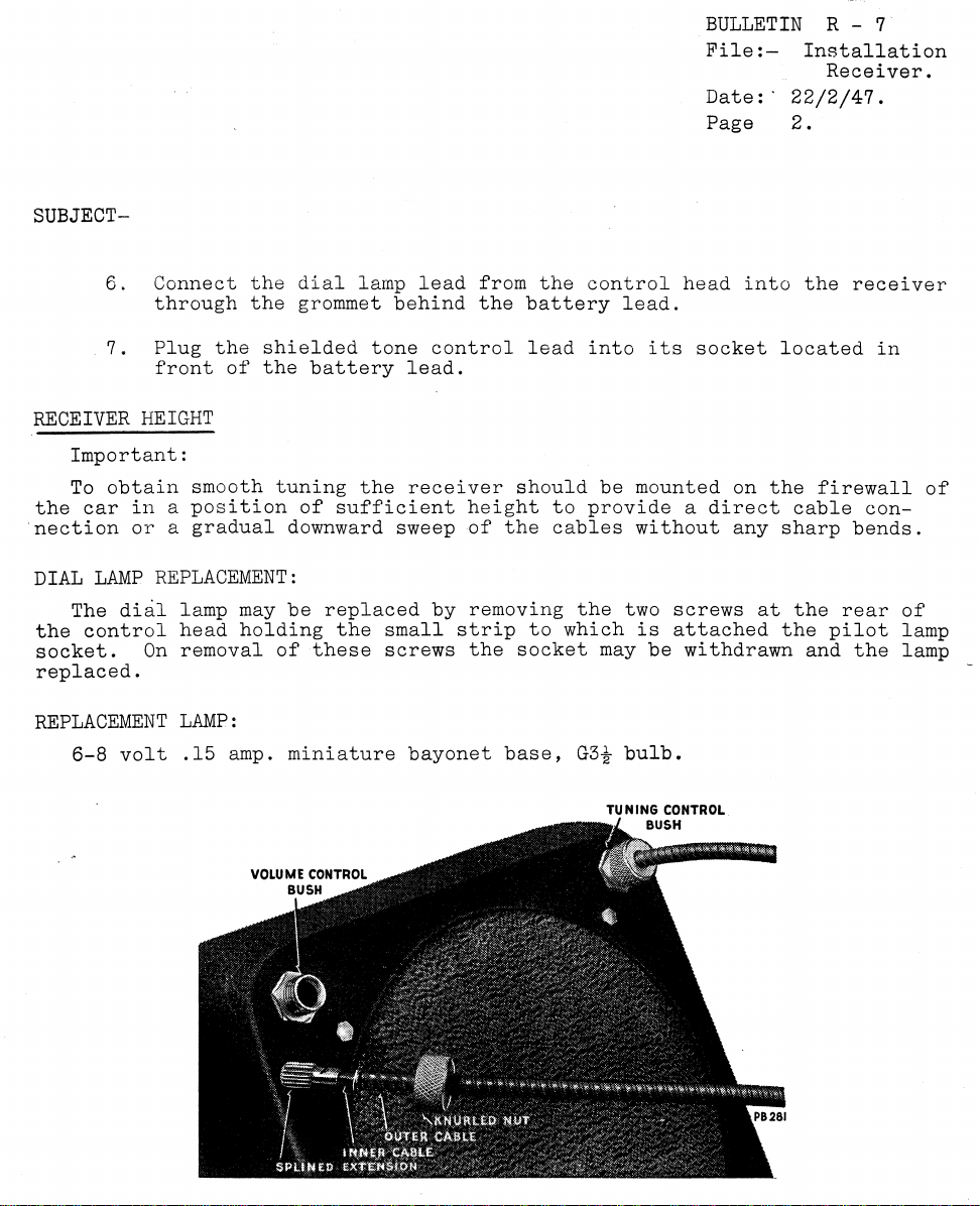
4. Insert the splined end of the control cables in through the bushes
in the receiver can and push into rubber mouldings on the conden
ser and volume control spindles. Lock cables in place on receiver
can with knurled nuts. The control cables are crossed over with
this installation due to the tuning knob being on the left.
5. To bring the pointer and condenser into alignment turn the tuning
knob (left hand knob) to the right for the full travel of the
pointer and then to the left for the full travel. This operation
automatically brings the pointer and condenser into alignment and
no further adjustment is necessary.
______
CABLE LENGTH (APPROX.)
BULLETIN R - 7
PileInstallation
Receiver.
Da t e : ' 22/2/47.
Page 2.
3UBJECT-
6. Connect the dial lamp lead from the control head into the receiver
through the grommet behind the battery lead.
7. Plug the shielded tone control lead into its socket located in
front of the battery lead.
RECEIVER HEIGHT
Important:
To obtain smooth tuning the receiver should be mounted on the firewall of
the car in a position of sufficient height to provide a direct cable con
nection or a gradual downward sweep of the cables without any sharp bends.
DIAL LAMP REPLACEMENT:
The dial lamp may be replaced by removing the two screws at the rear of
the control head holding the small strip to which is attached the pilot lamp
socket. On removal of these screws the socket may be withdrawn and the lamp
replaced.
REPLACEMENT LAMP:
6-8 volt .15 amp. miniature bayonet base, G3£ bulb.
TUNING CONTROL
ml BUSH
 Loading...