


Version 1.0
Published April 2015
Copyright©2015 ASRock INC. All rights reser ved.
Copyright Notice:
No part of this documentation may be reproduced, transcribed, transmitted, or
translated in any language, in any form or by any means, except duplication of
documentation by the purchaser for backup purpose, without written consent of
ASRock Inc.
Products and corporate names appearing in this documentation may or may not
be registered trademarks or copyrights of their respective companies, and are used
only for identication or explanation and to the owners’ benet, without intent to
infringe.
Disclaimer:
Specications and information contained in this documentation are furnished for
informational use only and subject to change without notice, and should not be
constructed as a commitment by ASRock. ASRock assumes no responsibility for
any errors or omissions that may appear in this documentation.
With respect to the contents of this documentation, ASRock does not provide
warranty of any kind, either expressed or implied, including but not limited to
the implied warranties or conditions of merchantability or tness for a particular
purpose.
In no event shall ASRock, its directors, ocers, employees, or agents be liable for
any indirect, special, incidental, or consequential damages (including damages for
loss of prots, loss of business, loss of data, interruption of business and the like),
even if ASRock has been advised of the possibilit y of such damages arising from any
defect or error in the documentation or product.
is device complies with Part 15 of the FCC Rules. Operation is subject to the following
two conditions:
(1) this device may not cause harmful interference, and
(2) this device must accept any interference received, including interference that
may cause undesired operation.
CALIFORNIA, USA ONLY
e Lithium battery adopted on this motherboard contains Perchlorate, a toxic substance
controlled in Perchlorate Best Management Practices (BMP) regulations passed by the
California Legislature. When you discard the Lithium battery in California, USA, please
follow the related regulations in advance.
“Perchlorate Material-special handling may apply, see ww w.dtsc.ca.gov/hazardouswaste/
perchlorate”
ASRock Website: http://www.asrock.com
Manufactured under license under U.S. Patent Nos: 5,956,674; 5,974,380; 6,487,535;
7,003,467 & other U.S. and worldwide patents issued & pending. DTS, the Symbol, &
DTS and the Symbol together is a registered trademark & DTS Connect, DTS Interactive,
DTS Neo:PC are trademarks of DTS, Inc. Product includes soware.
© DTS, Inc., All Rights Reserved.

Contents
Chapter 1 Introduction 1
1.1 Package Contents 1
1.2 Specications 2
1.3 Motherboard Layout 7
1.4 I/O Panel 10
Chapter 2 Installation 12
2.1 Installing the CPU 13
2.2 Installing the CPU Fan and Heatsink 16
2.3 Installation of Memory Modules (DIMM) 17
2.4 Expansion Slots (PCI Express Slots) 19
2.5 Jumpers Setup 21
2.6 Onboard Headers and Connectors 22
2.7 Smart Switches 28
2.8 Dr. Debug 31
2.9 Post Status Checker 33
2.10 SLI
TM
, 3-Way SLI
TM
, 4-Way SLI
TM
and Quad SLITM Operation
Guide 34
2.10.1 Installing Two SLI
TM
-Ready Graphics Cards 34
2.10.2 Installing Three SLI
TM
-Ready Graphics Cards 36
2.10.3 Installing Four SLI
TM
-Ready Graphics Cards 38
2.10.4 Driver Installation and Setup 40
2.11 CrossFireX
TM
, 3-Way CrossFireXTM , 4-Way CrossFireX
TM
and Quad CrossFireXTM Operation Guide 41

2.11.1 Installing Two CrossFireXTM-Ready Graphics Cards 41
2.11.2 Installing Three CrossFireX
TM
-Ready Graphics Cards 42
2.11.3 Installing Four CrossFireX
TM
-Ready Graphics Cards 43
2.11.4 Driver Installation and Setup 44
2.12 M.2_SSD (NGFF) Module Installation Guide 45
2.13 HDD Saver Cable Installation Guide 48
2.14 ASRock USB 3.1 Card/A+A Installation Guide 49
Chapter 3 Software and Utilities Operation 51
3.1 Installing Drivers 51
3.2 Formula Drive 52
3.3 ASRock APP Shop 58
3.3.1 UI Overview 58
3.3.2 Apps 59
3.3.3 BIOS & Drivers 62
3.3.4 Setting 63
3.4 Start8 64
Chapter 4 UEFI SETUP UTILITY 70
4.1 Introduction 70
4.1.1 UEFI Menu Bar 70
4.1.2 Navigation Keys 71
4.2 Main Screen 72
4.3 OC Tweaker Screen 73
4.4 Advanced Screen 83
4.4.1 CPU Conguration 84

4.4.2 Chipset Conguration 86
4.4.3 Storage Conguration 89
4.4.4 Super IO Conguration 90
4.4.5 ACPI Conguration 91
4.4.6 USB Conguration 92
4.4.7 Trusted Computing 93
4.5 Tools 94
4.6 Hardware Health Event Monitoring Screen 99
4.7 Security Screen 101
4.8 Boot Screen 102
4.9 Exit Screen 105

1
English
X99 OC Formula/3.1
Chapter 1 Introduction
ank you for purchasing ASRock X99 OC Formula/3.1 motherboard, a reliable
motherboard produced under ASRock’s consistently stringent quality control.
It delivers excellent performance with robust design conforming to ASRock’s
commitment to quality and endurance.
In this documentation, Chapter 1 and 2 contains the introduction of the
motherboard and step-by-step installation guides. Chapter 3 contains the operation
guide of the soware and utilities. Chapter 4 contains the conguration guide of
the BIOS setup.
1.1 Package Contents
•
ASRock X99 OC Formula/3.1 Motherboard (EATX Form Factor)
•
ASRock X99 OC Formula/3.1 Quick Installation Guide
•
ASRock X99 OC Formula/3.1 Support CD
•
1 x I/O Panel Shield
•
1 x ASRock USB 3.1 Card/A+A
•
3 x ASRock Flexible SLI Bridge Connector Cables (2 x 10 cm, 1 x 14 cm)
•
6 x Serial ATA (SATA) Data Cables (Optional)
•
1 x HDD Saver Cable
•
2 x Screws for M.2 Sockets
•
1 x Screw for mini-PCIe Slot
Becau se the motherboard specications and th e BIOS soware might be updated, the
content of this documentation will be subject to change without notice. In ca se any modications of this documentation occur, the updated version will be available on ASRock ’s
website w ithout further notice. If you require technical support related to this motherboard, please visit our website for specic information about the model you are using. You
may nd the l atest VGA cards and CPU suppor t list on ASRock’s website a s well. ASRock
website http://www.asrock.com.

2
English
1.2 Specications
Platform
•
EATX Form Factor
•
8 Layer PCB
•
4 x 2oz copper
•
High Density Glass Fabric PCB
CPU
•
Supports Intel® Core
TM
i7 and Xeon® 18-Core Processors
Family for the LGA 2011-3 Socket
•
Digi Power design
•
12 Power Phase design (Supports up to 1300w)
•
Supports Intel® Turbo Boost 2.0 Technology
•
Supports Untied Overclocking Technology
Chipset
•
Intel® X99
Memory
•
Quad Channel DDR4 Memory Technology
•
8 x DDR4 DIMM Slots
•
Supports DDR4 3400+(OC)*/2933(OC)/2800(OC)/2400(
OC)/2133 non-ECC, un-buered memory
* Please refer to Memory Support List on ASRock's website for
more information. (http://www.asrock.com/)
•
Supports non-ECC x8 (8 bit) RDIMM (Registered DIMM)/
x8 (8 bit) UDIMM
•
Supports DDR4 ECC x8 (8 bit) RDIMM/x8 (8 bit) UDIMM
with Intel® Xeon® processors E5 series in the LGA 2011-3
Socket
•
Max. capacity of system memory: 128GB (see CAUTION)
•
Supports Intel® Extreme Memory Prole (X MP) 2.0
Expansion
Slot
•
5 x PCI Express 3.0 x16 Slots (PCIE1/PCIE2/PCIE3/PCIE4/
PCIE5: single at x16 (PCIE1); dual at x16 (PCIE1) / x16
(PCIE4); triple at x8 (PCIE1) / x8 (PCIE2) / x16 (PCIE4);
quad at x8 (PCIE1) / x8 (PCIE2) / x8 (PCIE4) / x8 (PCIE5))
* If you install CPU with 28 lanes, PCIE1/PCIE2/PCIE3/PCIE4/
PCIE5 will run at x16/x0/x4/x8/x0 or x8/x8/x4/x8/x0, and PCIE5
will be disabled.
* To support 3-Way CrossFireXTM and 3-Way SLITM when using
CPU with 28 lanes, please install VGA cards to PCIE1/PCIE2/
PCIE4 (x8/x8/x8).

3
English
X99 OC Formula/3.1
* If Ultra M.2 PCI Express module is installed, PCIE3 slot will
be disabled.
•
1 x Half Mini-PCI Express Slot
•
Supports AMD Quad CrossFireXTM, 4-Way CrossFireXTM,
3-Way CrossFireXTM and CrossFireXTM
•
Supports NVIDIA® Quad SLITM, 4-Way SLITM, 3-Way SLITM
and SLI
TM
* If you install CPU with 28 lanes, 4-Way CrossFireXTM and
4-Wa y S LITM are not supported.
Audio
•
7.1 CH HD Audio with Content Protection (Realtek
ALC1150 Audio Codec)
•
Premium Blu-ray Audio support
•
Supports Surge Protection (ASRock Full Spike Protection)
•
Supports Purity Sound ™ 2
- Nichicon Fine Gold Series Audio Caps
- 115dB SNR DAC with Dierential Amplier
- TI® NE5532 Premium Headset Amplier (Supports up to
600 Ohms headsets)
- Direct Drive Technology
- EMI Shielding Cover
- PCB Isolate Shielding
•
Supports DTS Connect
LAN
•
1 x Intel® I218V (Gigabit LAN PHY 10/100/1000 Mb/s)
•
1 x Qualcomm® Atheros® AR8171 (PCIE x1 Gigabit LAN
10/100/1000 Mb/s)
•
Supports Qualcomm® Atheros® Security Wake On Internet
Technology (on Qualcomm® Atheros® AR8171)
•
Supports Wake-On-LAN
•
Supports Lightning/ESD Protection (ASRock Full Spike
Protection)
•
Supports Energy Ecient Ethernet 802.3az
•
Supports PXE
Rear Panel
I/O
•
1 x PS/2 Mouse/Keyboard Port
•
1 x Optical SPDIF Out Port
•
2 x USB 2.0 Ports (Supports ESD Protection (ASRock Full
Spike Protection))

4
English
•
1 x USB 3.1 Type-C Port (10 Gb/s) (Supports ESD Protection
(ASRock Full Spike Protection))
•
4 x USB 3.0 Ports (ASMedia ASM1074 hub) (Supports ESD
Protection (ASRock Full Spike Protection))
•
2 x USB 3.0 Ports (Supports ESD Protection (ASRock Full
Spike Protection))
•
2 x RJ-45 LAN Ports with LED (ACT/LINK LED and SPEED
LE D)
•
1 x Clear CMOS Switch
•
HD Audio Jacks: Rear Speaker / Central / Bass / Line in /
Front Speaker / Microphone
ASRock
USB 3.1
Card/A+A
•
2 x USB 3.1 Type-A Ports (10 Gb/s) (Supports ESD Protection
(ASRock Full Spike Protection))
Storage
•
10 x SATA3 6.0 Gb/s Connectors, support R AID (RAID
0, RAID 1, RAID 5, RAID 10 and Intel Rapid Storage 13),
NCQ, AHCI, Hot Plug and ASRock HDD Saver Technology
(S_SATA3_3 connector is shared with M.2 Socket (M2_1))
* RAID is supported on SATA3_0 ~ SATA3_5 ports only.
•
1 x SATA Express 10 Gb/s Connector (shared with SATA3_4
and SATA3_5)
* Support to be announced
•
1 x Ultra M.2 Socket (ULTRA_M2), supports M.2 PCI
Express module up to Gen3 x4 (32 Gb/s)
•
1 x M.2_SSD (NGFF) Socket 3 (M2_1), supports M.2 SATA3
6.0 Gb/s module and M.2 PCI Express module up to Gen2 x
2 (10 Gb/s)
Connector
•
1 x COM Port Header
•
1 x TPM Header
•
1 x Power LED Header
•
2 x CPU Fan Connectors (1 x 4-pin, 1 x 3-pin)
•
3 x Chassis Fan Connectors (1 x 4-pin, 2 x 3-pin) (Smart Fan
Speed Control)
•
1 x Power Fan Connector (3-pin)
•
1 x 24 pin ATX Power Connector
•
1 x 8 pin 12V Power Connector (Hi-Density Power
Conn ector)

5
English
X99 OC Formula/3.1
•
1 x 4 pin 12V Power Connector (Hi-Density Power
Conn ector)
•
1 x HDD Saver Connector
•
1 x PCIe Power Connector
•
1 x Front Panel Audio Connector
•
1 x underbolt AIC Connector
•
2 x USB 2.0 Headers (support 4 USB 2.0 ports) (Supports
ESD Protection (ASRock Full Spike Protection))
•
1 x Vertical Type A USB 3.0
•
2 x USB 3.0 Headers (Support 4 USB 3.0 ports) (ASMedia
ASM1074 hub) (Supports ESD Protection (ASRock Full Spike
Protection))
•
1 x Dr. Debug with LED
•
1 x Power Switch with LED
•
1 x Reset Switch with LED
•
V-ProbeTM: 7-set of onboard voltage measurement points laid
•
Rapid OC Buttons: +/- buttons to adjust OC frequency
•
1 x Menu Button
•
1 x PCIe ON/OFF Switch
•
1 x Slow Mode Switch
•
1 x LN2 Mode Switch
•
1 x BIOS Selection Switch
•
1 x Direct Key Button
BIOS
Feature
•
2 x 128Mb AMI UEFI Legal BIOS with multilingual GUI
support (1 x Main BIOS and 1 x Backup BIOS)
•
Supports Secure Backup UEFI Technology
•
ACPI 1.1 Compliant wake up events
•
SMBIOS 2.3.1 Support
•
CPU, DRAM, PCH 1.05V, PCH 1.5V, VPPM Voltage Multi-
adjustment
Hardware
Monitor
•
CPU/Chassis temperature sensing
•
CPU/Chassis/Power Fan Tachometer
•
CPU/Chassis Quiet Fan (Auto adjust chassis fan speed by
CPU temperature)
•
CPU/Chassis Fan multi-speed control
•
Voltage monitoring: +12V, +5V, +3.3V, CPU Input Voltage,
CPU Internal Voltages
•
Multi ermal Sensor
6
English
Please realize that the re is a certain risk involved with overclocking, including adjusting
the setting in the BIO S, applying Untied Overclocking Technology, or using third-par ty
overclocking tools. O verclocking may aect your syste m’s stability, or even cause d amage to
the components and devices of your syste m. It should be done at your own risk and expe nse.
We are not responsibl e for possible damage caused by overclocking.
* For detailed product information, please visit our website: http://www.asrock .com
Due to limitation , the actual memory size may be less than 4GB for the re servation for s ystem usage under Windows® 32-bit operating systems . Windows® 64-bit operating systems
do not have s uch limitations. You can use ASRock XFast RAM to utilize the memory that
Windows® cannot use.
OS
•
Microso® Windows® 10 64-bit / 8.1 32-bit / 8.1 64-bit / 8 32-
bit / 8 64-bit / 7 32-bit / 7 64-bit
Certications
•
FCC, CE, WHQL
•
ErP/EuP Ready (ErP/EuP ready power supply is required)
7
English
X99 OC Formula/3.1
Super
I/O
Super
I/O
ATXP WR 1
1
USB3_7_ 8
LAN
LAN
PCIE1
PCIE4
PLED1
1
1
SPEAKER1
HDLED RESET
PLED PWRBTN
PANEL1
1
USB5_6
1
1
USB3_4
COM1
1
X99 OC Formula/3.1
PCIE5
S_SATA3_2 _3
SATA3_0_3
SATA3_1_4
SATA3_2_5
CHA_FAN1
CPU_FAN1
CPU_FAN2
PWR_FAN1
RoHS
14
16
15
21
13
12
9
10
11
18
22
20
23
24
25
27
26
28
29
30
31
S_SATA3_0 _1
3
4
5
8
DDR4 _A2 (64 b it, 288 -pin mo dule)
DDR4 _A1 (64 b it, 288 -pin mo dule)
DDR4 _B2 (64 b it, 288 -pin mo dule)
DDR4 _B1 (64 b it, 288 -pin mo dule)
2
1
46
Purity
Sound 2
TM
Ultra M .2
PCIe Ge n3 x4
128Mb
BIOS
BIOS_A
BIOS_A_LED
128Mb
BIOS
BIOS_A
BIOS_A_LED
1
TPMS1
CLRMOS1
1
CT2CT3CT4CT5
1
HD_AUDIO1
T BT1
1
CHA_FAN3
19
17
1
SATA_PWR_1
CT1
DDR4 _D1 (64 b it, 288 -pin mo dule)
DDR4 _D2 (64 b it, 288 -pin mo dule)
DDR4 _C1 (64 b it, 288 -pin mo dule)
DDR4 _C2 (64 b it, 288 -pin mo dule)
7
6
2011-3 Socket
Vertica l
Type A USB
USB3_11
1
USB3_9_ 10
Dr.
Debug
Reset Power
34
33
35
36
37
38
39
40
41
42
43
44
45
32
BIOS_SEL 1
AB
MINI _PCIE 1
Top:
Central/Bass
Center:
REAR SPK
Top:
LINE IN
Center:
FRONT
Bottom:
Optical
SPDIF
Bottom:
MIC IN
CLRC
BTN1
Top:
RJ-45
USB 3.0
T: USB5
B: USB6
RJ-45
USB 2.0
T: USB1
B: USB2
PS2
Keybo ard
/Mous e
USB 3.0
T: USB1
B: USB2
USB 3.0
T: USB3
B: USB4
CHA_FAN2
8-Lay er PCB
+
-
ON
1 2 3 4
ON
OFF
ON
OFF
MENU
PCIE_PWR1
CMOS
Battery
Intel
X99
LN2MODE1 SLOWMODE1SWITCH1
CPU
DRAM
VGA
BOOT
ATX12V1
ATX12V2
DIRKEY1
PCIE2
ULTRA _M2
CT2CT3CT4CT5
PCIE3
M2_1
SATAE_1
USB 3.1
(Type-C)
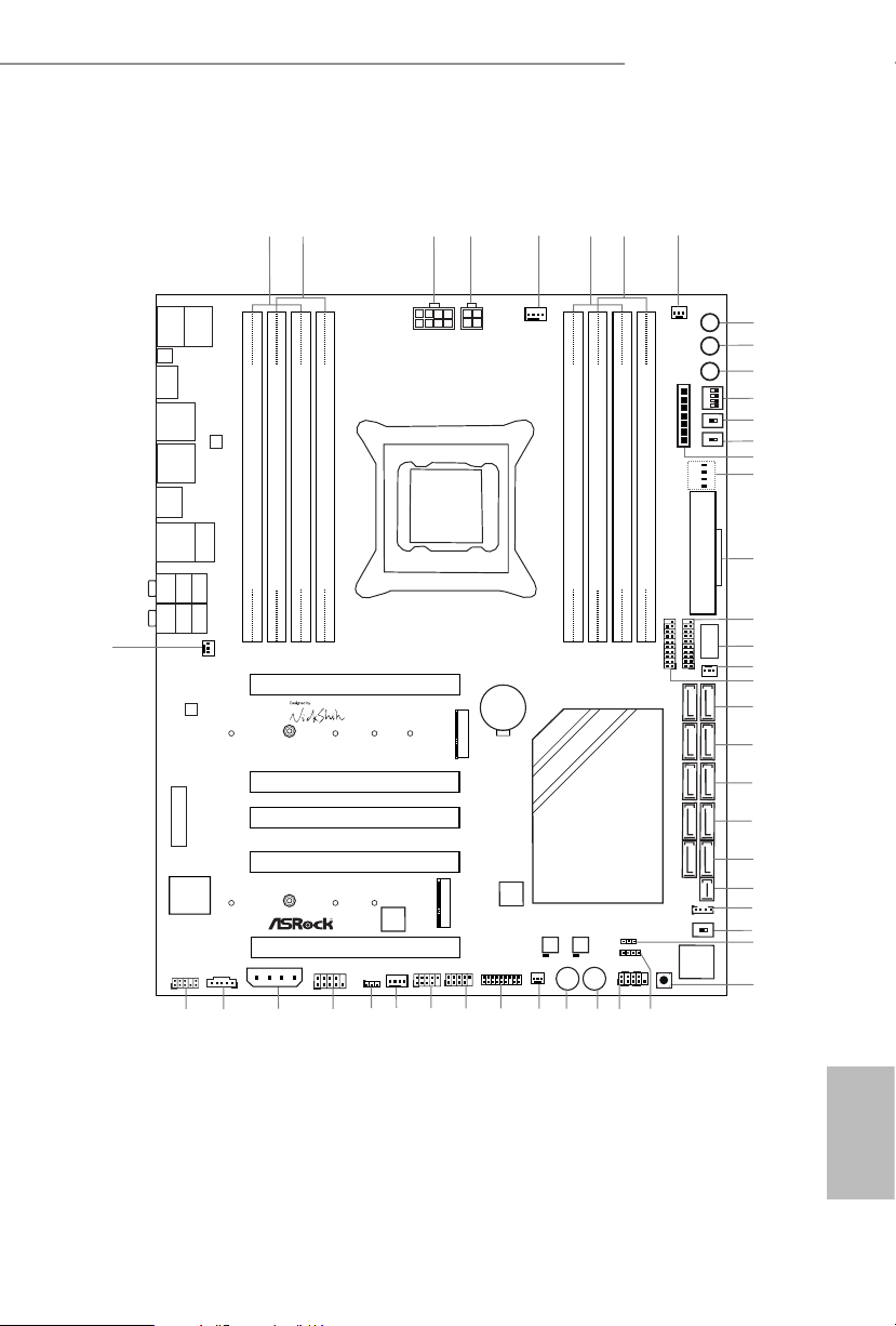
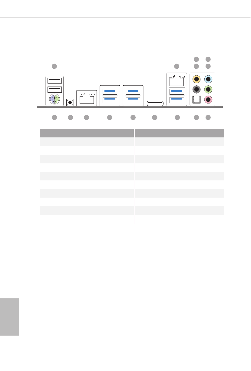
1.3 Motherboard Layout

8
English
No. Description
1 2 x 288-pin DDR4 DIMM Slots (DDR4_A1, DDR4_B1)
2 2 x 288-pin DDR4 DIMM Slots (DDR4_A2, DDR4_B2)
3 8 pin ATX 12V Power Connector (ATX12V1)
4 4 pin ATX 12V Power Connector (ATX12V2)
5 CPU Fan Connector (CPU_FAN1)
6 2 x 288-pin DDR4 DIMM Slots (DDR4_D2, DDR4_C2)
7 2 x 288-pin DDR4 DIMM Slots (DDR4_D1, DDR4_C1)
8 CPU Fan Connector (CPU_FAN2)
9 Rapid OC Button (+) (PLUS)
10 Rapid OC Button (–) (MINUS)
11 Menu Button (MENU)
12 PCIe ON/OFF Switch (SWITCH1)
13 LN2 Mode Switch (LN2MODE)
14 Slow Mode Switch (SLOWMODE)
15 V-Probe
TM
(VOL _CON1)
16 Post Status Checker (PSC)
17 ATX Power Connector (ATXPWR1)
18 USB 3.0 Header (USB3_7_8)
19 Vertical Type A USB 3.0 (USB3_11)
20 Chassis Fan Connector (CHA_FAN3)
21 USB 3.0 Header (USB3_9_10)
22 SATA3 Connectors (S_SATA3_0_1)
23 SATA3 Connectors (S_SATA3_2 _3)
24 SATA3 Connectors (SATA3_0_3)
25 SATA3 Connectors (SATA3_1_ 4)
26 SATA3 Connectors (SATA3_2 _5)
27 SATA Express Connector (SATAE_1)
28 HDD Saver Connector (SATA_PWR_1)
29 BIOS Selection Switch (BIOS_SEL1)
30 Power LED Header (PLED1)
31 Direct Key Button (DIRKEY1)
32 Chassis Speaker Header (SPEAKER1)
33 System Panel Header (PANEL1)

9
English
X99 OC Formula/3.1
No. Description
34 Power Switch (PWR)
35 Reset Switch (RST)
36 Chassis Fan Connector (CHA_FAN2)
37 TPM Header (TPMS1)
38 USB 2.0 Header (USB3_4)
39 USB 2.0 Header (USB5_6)
40 Chassis Fan Connector (CHA_FAN1)
41 Clear CMOS Jumper (CLRCMOS1)
42 COM Port Header (COM1)
43 PCIe Power Connector (PCIE_PWR1)
44 underbolt AIC Connector (TB1)
45 Front Panel Audio Header (HD_AUDIO1)
46 Power Fan Connector (PWR_FAN1)
10
English
1.4 I/O Panel
No. Description No. Description
1 USB 2.0 Ports (USB12) 10 USB 3.1 Type-C Port (USB31_TC_1)
2 LAN RJ-45 Port (ASMedia ASM1142)
(Qualcomm® Atheros® AR8171)* 11 USB 3.0 Ports (USB3_34)
3 Central / Bass (Orange) (ASMedia ASM1074 hub)
4 Rear Speaker (Black) 12 USB 3.0 Ports (USB3_12)
5 Line In (Light Blue) (ASMedia ASM1074 hub)
6 Front Speaker (Lime)*** 13 LAN RJ-45 Port
7 Microphone (Pink) (Intel® I218V)**
8 Optical SPDIF Out Port 14 Clear CMOS Switch
9 USB 3.0 Ports (USB3_56) 15 PS/2 Mouse/Keyboard Port
1
15 78911 10121314
2 436
5
11
English
X99 OC Formula/3.1
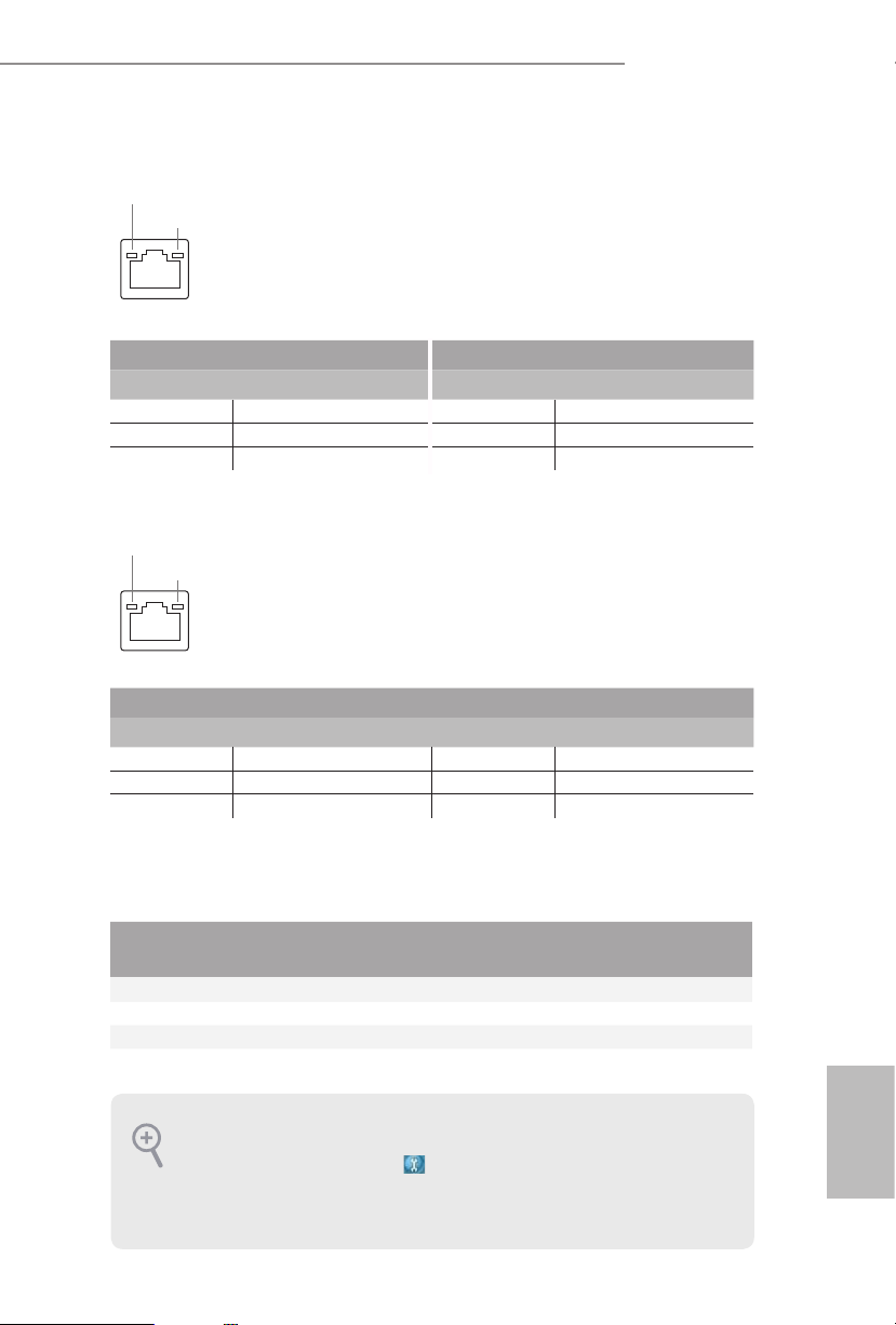
* ere are two LEDs on each LAN port. Please refer to the table below for the LAN port LED indications.
Activity / Link LED Speed LED
Status Description Status Description
O No Link O 10Mbps connection
Blinking Data Activity Orange 100Mbps connection
On Link Green 1Gbps connection
** ere are two LEDs on each LAN port. Please refer to the table below for the LAN port LED indications.
Activity / Link LED Speed LED
Status Description Status Description
O No Link O 10Mbps connection
Blinking Data Activity Green 100Mbps connection
On Link Green 1Gbps connection
***If you use a 2-channel speaker, plea se conne ct the speaker’s plug into “Front Speaker Jack”. See the table below
for connection d etails in accordance w ith the ty pe of speaker you use.
Audio Output
Channels
Front Speaker
(No. 6)
Rear Speaker
(No. 4)
Central / Bass
(No. 3)
Line In
(No. 5)
2 V -- -- --
4 V V -- --
6 V V V --
8 V V V V
To enable Multi-Streaming, you need to c onnect a front panel audio cable to the front
panel au dio header. Aer restarting your computer, you will nd the “Mixer” tool on your
system. Plea se select “Mixe r ToolBox” , click “Enable playback multi-streaming”, and
click “ok”. Choose “2CH”, “4CH”, “6CH”, or “8CH” and then you are allowed to select
“Realtek HDA Primary output” to u se the Rear Speaker, Central/Bass, and Front Spea ker,
or select “Realtek HDA Audio 2nd output” to use the front panel audio.
ACT/LINK LED
SPEED LED
LAN Por t
ACT/LINK LED
SPEED LED
LAN Por t

12
English
is is an EATX form factor motherboard. Before you install the motherboard,
study the conguration of your chassis to ensure that the motherboard ts into it.
Pre-installation Precautions
Take note of the following precautions before you install motherboard components
or change any motherboard settings.
•
Make sure to unplug the power cord before installing or removing the motherboard
components. Failure to do so may cause physical injuries and damages to motherboard
components.
•
In order to avoid damage from static electricity to the motherboard’s components,
NEVER place your motherboard directly on a carpet. Also remember to use a grounded
wrist strap or touch a safety grounded object before you handle the components.
•
Hold components by the edges and do not touch the ICs.
•
Whenever you uninstall any components, place them on a grounded anti-static pad or
in the bag that comes with the components.
•
When placing screws to secure the motherboard to the chassis, please do not over-
tighten the screws! Doing so may damage the motherboard.
Chapter 2 Installation
13
English
X99 OC Formula/3.1
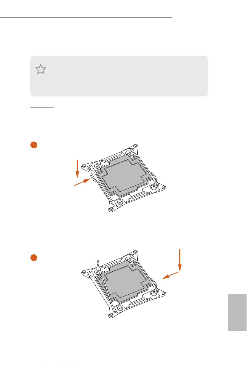
2.1 Installing the CPU
CAU TION:
Please note that X99 platform is only compatible with the LGA 2011-3 socket, which is
incompatible with the LGA 2011 socket (for X79 platform).
1. Before you insert the 2011- 3-Pin CPU into the socke t, please check if the Pn P cap is on
the socket, if the CPU surfa ce is unclean, or if there are any bent pins in the socket. Do
not force to inser t the CPU into the socket if above situation is found. Otherwi se, the CPU
will be seriously damaged.
2. Unplug all power c ables before in stalling the CPU.
A
B
A
B
1
2

14
English
4
A
3
B
5
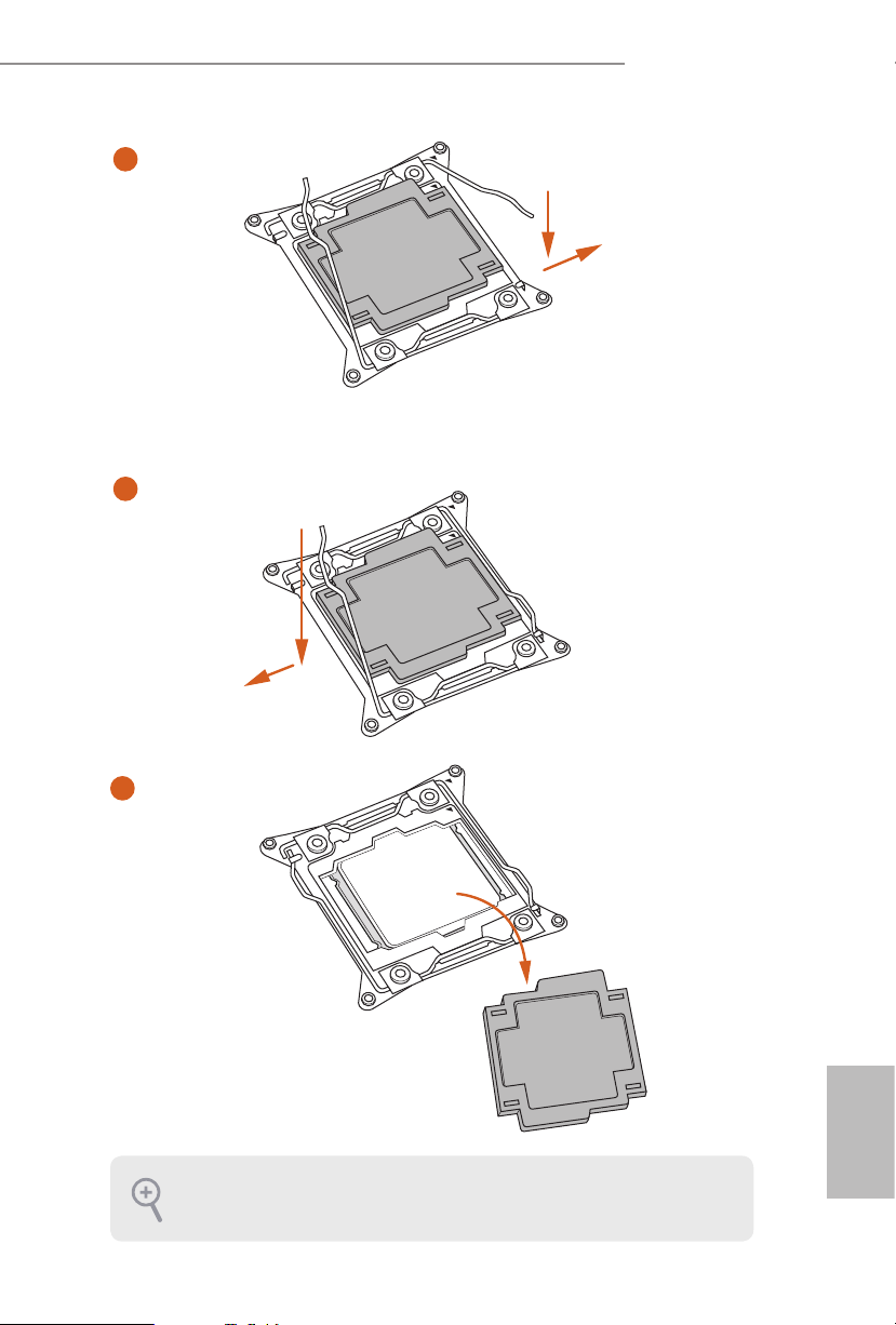
15
English
X99 OC Formula/3.1
Please save and replace the cover if the processor i s removed. e cover must be placed if
you wish to return the motherboard for aer se rvice.
6
A
B
8
B
7
A
16
English
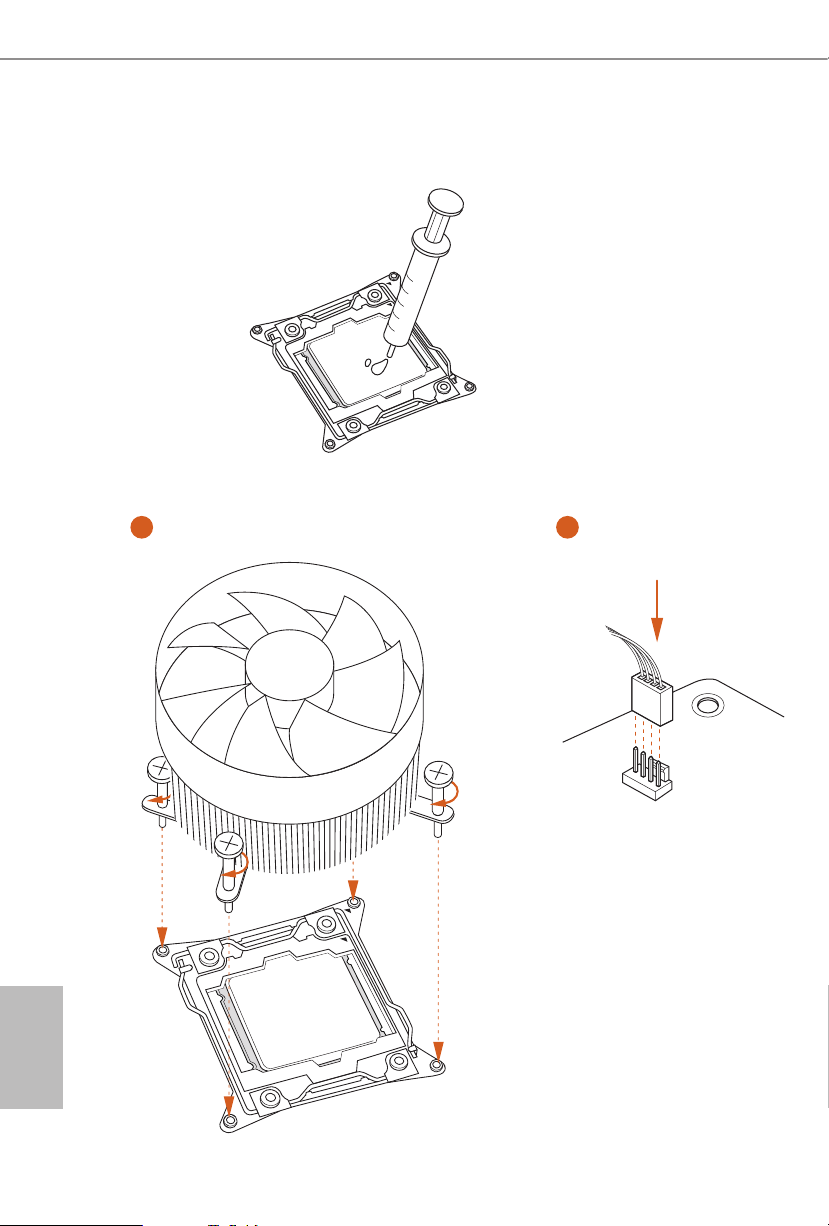
2.2 Installing the CPU Fan and Heatsink
CPU_
FAN
1 2
17
English
X99 OC Formula/3.1
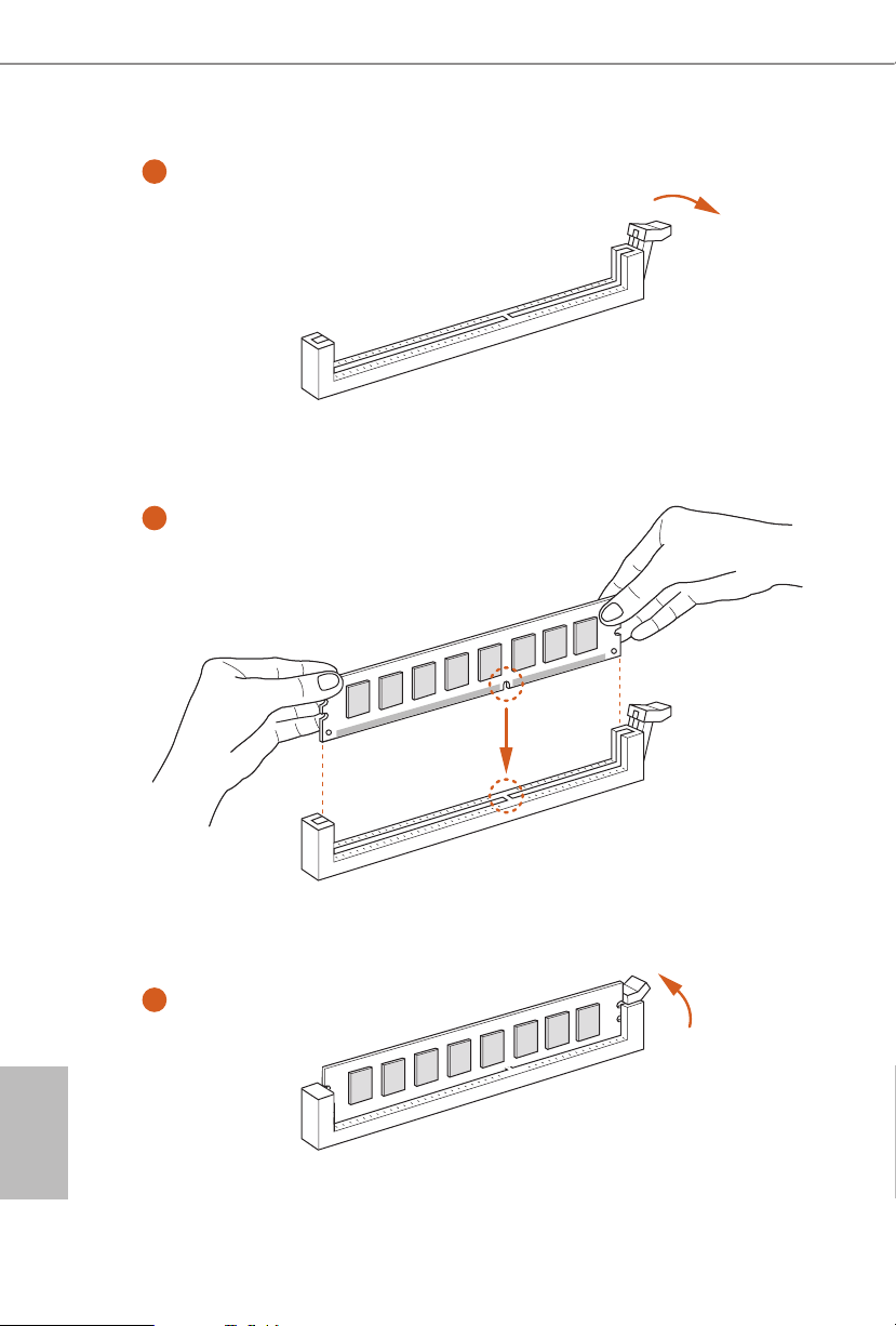
2.3 Installation of Memory Modules (DIMM)
is motherboard provides eight 288-pin DDR4 (Double Data Rate 4) DIMM slots, and
supports Quad Channel Memory Technology.
Quad Channel Memory Conguration
Priority 1 2
DDR4_A1
Populated Populated
DDR4_A2
Populated
DDR4_B1
Populated Populated
DDR4_B2
Populated
DDR4_C1
Populated Populated
DDR4_C2
Populated
DDR4_D1
Populated Populated
DDR4_D2
Populated
•
Due to Intel® CPU spec denition, please install the memory modules on DDR4_A1,
DDR4_B1, DDR4_C1 and DDR4_D1 for rst priority. If the four DDR4 DIMM slots
above are fully installed, and you want to use more than four memory modules, please
install the other memor y modules from le to right (from DDR4_ A2, DDR4_B2,
DDR4_D2 to DDR4_C2.)
•
If only two memory modules are installed in the DDR4 DIMM slots, then Dual
Channel Memory Technology is activated. If three memory modules are insta lled, then
Triple Channel Memory Technology is activated. If more than four memory modules
are installed in the DDR4 DIMM slots, then Quad Channel Memory Technolog y is
activated.
1. For quad chann el cong uration, you always need to in stall identical (the same b rand,
speed , size and chip-type) DDR4 DIMM pairs.
2. It is not allowed to install a DDR, DDR2 or DDR3 memory module into a DDR4 slot;
otherwise , this motherboard and DIMM may be dam aged.
3. e DIMM only ts in one correct orientation. It wil l cause permanent damage to the
motherboard and the DIMM if you force the DIMM into the slot at incorrect orientation.
18
English
1
2
3
19
English
X99 OC Formula/3.1
2.4 Expansion Slots (PCI Express Slots)
ere are 5 PCI Express slots and 1 mini-PCI Express slot on the motherboard.
mini-PCIe slots:
MINI_PCIE1 (mini-PCIe slot) is used for WiFi module.
PCIe slots:
PCIE1 (PCIe 3.0 x16 slot) is used for PCI Express x16 lane width graphics cards.
PCIE2 (PCIe 3.0 x16 slot) is used for PCI Express x8 lane width graphics cards.
PCIE3 (PCIe 3.0 x16 slot) is used for PCI Express x8 lane width cards, such as
underbolt™ add-in card.
PCIE4 (PCIe 3.0 x16 slot) is used for PCI Express x16 lane width graphics cards.
PCIE5 (PCIe 3.0 x16 slot) is used for PCI Express x8 lane width graphics cards.
PCIe Slot Congurations (For CPU with 40 PCIe lanes)
PCIE1 PCIE2 PCIE3 PCIE4 PCIE5
Single Graphics Card x16 N/A N/A N/A N /A
Two Graphics Cards in
CrossFireX
TM
or SLITM
Mode
x16 N /A N/A x16 N /A
ree Graphics Cards in
3-Way CrossFireX
TM
Mode
or 3-Way SLITM Mode
x8 x8 N/A x 16 N /A
Four Graphics Cards in
4-Way CrossFireX
TM
Mode
or 4-Way SLITM Mode
x8 x8 N/A x8 x8
For a better ther mal environme nt, please connect a chassi s fan to the motherboard’s chassis fan connector (CHA_ FAN1, CHA_ FAN2 or CH A_FAN3) when using multipl e graphics
cards.
Before installing an ex pansion card, please make sure that the power supply is switched o
or the power cord is unplugged. Please read the documentation of the expansion card and
make necessary hardware settings for the card before you start the installation.
20
English
PCIe Slot Congurations (For CPU with 28 PCIe lanes)
For a better ther mal environme nt, please connect a chassi s fan to the motherboard’s chassis fan connector (CHA_ FAN1, CHA_ FAN2 or CH A_FAN3) when using multipl e graphics
cards.
PCIE1 PCIE2 PCIE3 PCIE4 PCIE5
Single Graphics Card x16 N/A N /A N/A N /A
Two Graphics Cards in
CrossFireX
TM
or SLITM
Mode
x16 N /A N/A x8 N /A
ree Graphics Cards in
3-Way CrossFireX
TM
Mode
or 3-Way SLITM Mode
x8 x8 N/A x8 N/A
*4-Way CrossFireX
TM
and 4-Way SLITM are not supported for CPU with 28 PCIe lanes.
21
English
X99 OC Formula/3.1
2.5 Jumpers Setup
e illustration shows how jumpers are setup. When the jumper cap is placed on
the pins, the jumper is “Short”. If no jumper cap is placed on the pins, the jumper
is “Open”. e illustration shows a 3-pin jumper whose pin1 and pin2 are “Short”
when a jumper cap is placed on these 2 pins.
Clear CMOS Jumper
(C LRC MO S1)
(see p.7, No. 41)
CLRCMOS1 allows you to clear the data in CMOS. To clear and reset the system
parameters to default setup, please turn o the computer and unplug the power
cord from the power supply. Aer waiting for 15 seconds, use a jumper cap to
short pin2 and pin3 on CLRCMOS1 for 5 seconds. However, please do not clear
the CMOS right aer you update the BIOS. If you need to clear the CMOS when
you just nish updating the BIOS, you must boot up the system rst, and then shut
it down before you do the clear-CMOS action. Please be noted that the password,
date, time, and user default prole will be cleared only if the CMOS battery is
removed.
Clear CMOS
Default
e Clear CMOS Switch has the same function a s the Clear CMOS jumper.
22
English
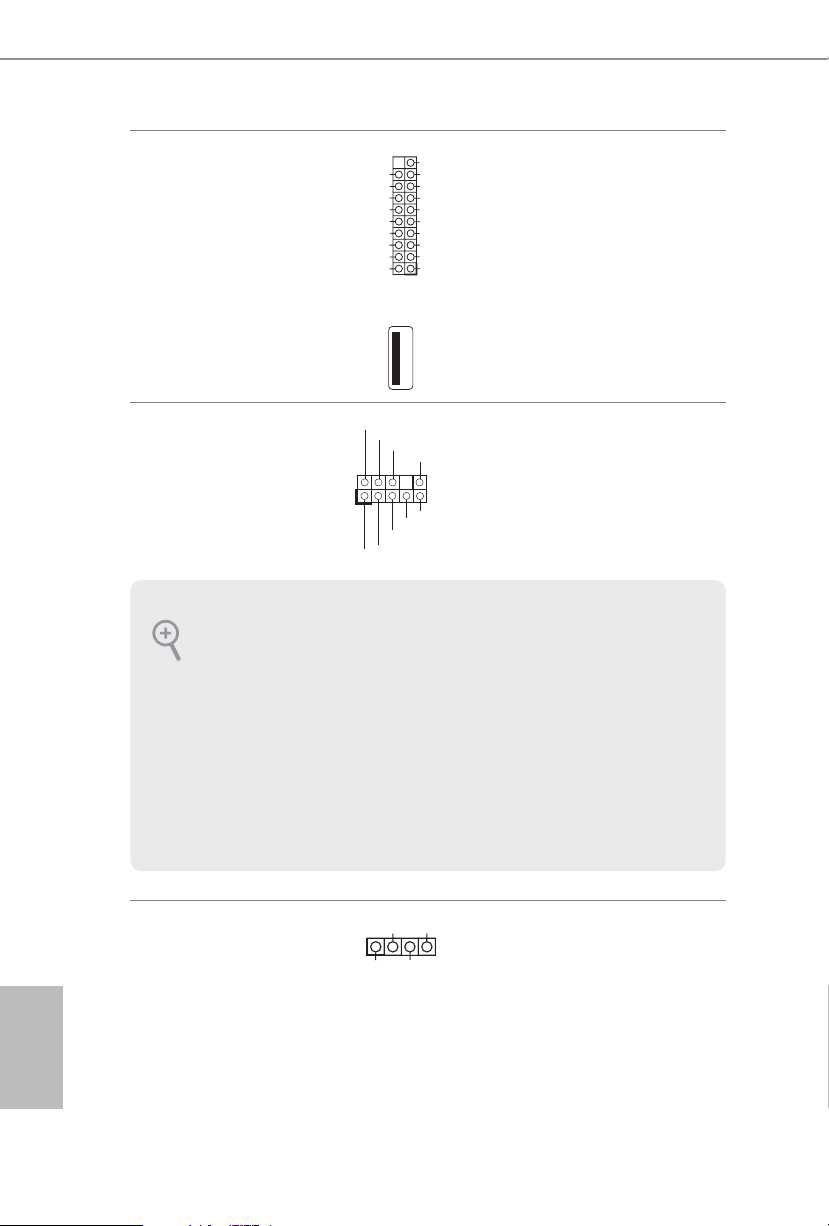
2.6 Onboard Headers and Connectors
System Panel Header
(9-pi n PANEL1)
(see p.7, No. 33)
Connect the power
switch, reset switch and
system status indicator on
the chassis to this header
according to the pin
assignments below. Note
the positive and negative
pins before connecting
the cables.
Power LED Header
(3-p in P L ED1)
(see p.7, No. 30)
Please connect the chassis
power LED to this header
to
indicate the system’s
power status.
GND
RESET#
PWRBTN#
PLED-
PLED+
GND
HDLED-
HDLED+
1
GND
PWRBTN (Power Switch):
Connec t to the power switch on the chassi s front panel. You may congure the way to tur n
o your system using the power switch.
RESET (Reset Switch):
Connec t to the reset switch on the chassi s front panel. Press the reset sw itch to restart the
computer if the computer f reezes and fails to per form a normal restar t.
PLED (Syste m Power LED):
Connec t to the power status indicator on th e chassis front panel . e LED is on when the
system is operating. e LED k eeps blinking when the system is in S1/S3 sleep state. e
LED is o when the system is in S4 slee p state or powered o (S5).
HDLED (Ha rd Drive Activity LED):
Connec t to the hard drive ac tivity LED on the chassis front panel. e LED is on when the
hard drive is reading or wr iting data.
e front panel de sign may dier by chassis. A front panel module mainly con sists of power
switch, reset switch , power LED, hard dr ive activity LED, speaker and etc. When conne cting your ch assi s front panel module to thi s header, make sure the wire a ssignments and the
pin assignments are matched correctly.
Onboard headers and connectors are NOT jumpers. Do NOT place jumper caps over th ese
heade rs and connectors. Placing jumper caps o ver the headers and connectors will cause
permanent damage to the motherboard.
1
PLED+
PLED+
PLED-
23
English
X99 OC Formula/3.1
Serial ATA3 Connectors
(S_ SATA3_ 0_1:
see p.7, No. 22)
(S_SATA3_2_3:
see p.7, No. 23)
(SATA3_0_3:
see p.7, No. 24)
(SATA3_1_4:
see p.7, No. 25)
(SATA3_ 2_5:
see p.7, No. 26)
ese ten SATA3
connectors support SATA
data cables for internal
storage devices with up
to 6.0 Gb/s data transfer
rate. If you install a M.2
SATA module to the
M.2 Socket (M2_1), the
internal S_SATA3_3 will
not function.
*If you install a M.2 PCI
Express module to the
M.2 Socket (M2_1), the
internal S_SATA3_3 will
still function.
* RAID is supported on
SATA3_0 ~ SATA3_5
ports only.
Serial ATA Express
Connector
(SATAE_1:
see p.7, No. 27)
Please connect either
SATA or PCIe storage
devices to this connector.
e SATA Express
connector is shared with
the SATA3_4 and the
SATA3_ 5.
*e SATA Express
interface is a combination
of SATAE_1, SATA3_5,
and SATA3_4.
USB 2.0 Headers
(9-pin USB3_4)
(see p.7, No. 38)
(9-pin USB5_6)
(see p.7, No. 39)
Besides two USB 2.0 ports
on the I/O panel, there
are two headers on this
motherboard. Each USB
2.0 header can support
two ports.
SATA3_0
SATA3_3
SATA3_2
SATA3_5
SATA3_1
SATA3_4
S_SATA3_0
S_SATA3_1
S_SATA3_2
S_SATA3_3
DUMMY
GND
GND
P+
P-
USB_PWR
P+
P-
USB_PWR
1
SATA3_5SATAE_1 SATA3_4
24
English
USB 3.0 Headers
(19-pin USB3_7_8)
(see p.7, No. 18)
(19-pin USB3_9_10)
(see p.7, No. 21)
(USB3_11)
(see p.7, No. 19)
Besides si x USB 3.0 ports
on the I/O panel, there
are two headers and one
port on this motherboard.
Each USB 3.0 header can
support two ports.
Front Panel Audio Header
(9-pin HD_ AUDIO1)
(see p.7, No. 45)
is header is for
connecting audio devices
to the front audio panel.
Chassis Speaker Header
(4-p in SPEAKER1)
(see p.7, No. 32)
Please connect the chassis
speaker to this header.
J_SENSE
OUT2_L
1
MIC_RET
PRESENCE#
GND
OUT2_R
MIC2_R
MIC2_L
OUT_RET
1
+5V
DUMMY
DUMMY
SPEAKER
1. High Denition Audio support s Jack Sensing, but the panel wire on the chassis mu st support HDA to function correctly. Please follow the in struction s in our manual and chassis
manual to install your system.
2. If you use an AC’97 audio panel , please install it to the front panel audio header by the
steps below:
A. Connect Mic_ IN (MIC) to MIC2_ L.
B. Conne ct Audio_R (RIN) to OUT2_R and Audio_ L (LIN) to OUT2_ L.
C. Connect Ground (GND) to Ground (GND).
D. MIC_ RET and OUT_RET are for the HD audio panel only. You don’t need to connect
them for the AC’97 audio panel .
E. To activate the front mic, go to the “FrontMic” Tab in the Realtek Control panel and
adjust “Recording Volume”.
1
IntA_PB_D+
Dummy
IntA_PB_D-
GND
IntA_PB_SSTX+
GND
IntA_PB_SSTX-
IntA_PB_SSRX+
IntA_PB_SSRX-
VbusVbus
Vbus
IntA_PA_SSRX-
IntA_PA_SSRX+
GND
IntA_PA_SSTX-
IntA_PA_SSTX+
GND
IntA_PA_D-
IntA_PA_D+
 Loading...