

Version 1.0
Published September 2014
Copyright©2014 ASRock INC. All rights reserved.
Copyright Notice:
No part of this documentation may be reproduced, transcribed, transmitted, or
translated in any language, in any form or by any means, except duplication of
documentation by the purchaser for backup purpose, without written consent of
ASRock Inc.
Products and corporate names appearing in this documentation may or may not
be registered trademarks or copyrights of their respective companies, and are used
only for identication or explanation and to the owners’ benet, without intent to
infringe.
Disclaimer:
Specications and information contained in this documentation are furnished for
informational use only and subject to change without notice, and should not be
constructed as a commitment by ASRock. ASRock assumes no responsibility for
any errors or omissions that may appear in this documentation.
With respect to the contents of this documentation, ASRock does not provide
warranty of any kind, either expressed or implied, including but not limited to
the implied warranties or conditions of merchantability or tness for a particular
purpose.
In no event shall ASRock, its directors, ocers, employees, or agents be liable for
any indirect, special, incidental, or consequential damages (including damages for
loss of prots, loss of business, loss of data, interruption of business and the like),
even if ASRock has been advised of the possibility of such damages arising from any
defect or error in the documentation or product.
is device complies with Part 15 of the FCC Rules. Operation is subject to the following
two conditions:
(1) this device may not cause harmful interference, and
(2) this device must accept any interference received, including interference that
may cause undesired operation.
CALIFORNIA, USA ONLY
e Lithium battery adopted on this motherboard contains Perchlorate, a toxic substance
controlled in Perchlorate Best Management Practices (BMP) regulations passed by the
California Legislature. When you discard the Lithium battery in California, USA, please
follow the related regulations in advance.
“Perchlorate Material-special handling may apply, see www.dtsc.ca.gov/hazardouswaste/
perchlorate”
ASRock Website: http://www.asrock.com
e terms HDMI™ and HDMI High-Denition Multimedia Interface, and the HDMI
logo are trademarks or registered trademarks of HDMI Licensing LLC in the United
States and other countries.
Manufactured under license under U.S. Patent Nos: 5,956,674; 5,974,380; 6,487,535;
7,003,467 & other U.S. and worldwide patents issued & pending. DTS, the Symbol, &
DTS and the Symbol together is a registered trademark & DTS Connect, DTS Interactive,
DTS Neo:PC are trademarks of DTS, Inc. Product includes soware.
© DTS, Inc., All Rights Reserved.
X99 Extreme6/ac / X99 Extreme6
Intel
X99
ATX12V1
Super
I/O
ATXP WR 1
1
USB3_5_ 6
LAN
LAN
PCIE1
Top:
Central/Bass
Center:
REAR SPK
Top:
LINE IN
Center:
FRONT
Bottom:
Optical
SPDIF
Bottom:
MIC IN
PCIE3
PLED1
1
1
SPEAKER1
HDLED RESET
PLED PWRBTN
PANEL1
1
USB5_6
1
1
USB3_4
COM1
1
1
HD_AUDIO1
X99 Extreme6/ac
PCIE5
SSATA3_2_ 3
SATA3_0_3
SATA3_1_4
SATA3_2_5
PCIE2
CHA_FAN1
CPU_FAN1
CPU_FAN2
PWR_FAN1
RoHS
9
8
11
10
13
14
15
16
17
22
26
273233
CLRC
BTN1
ESATA1
Top:
RJ-45
USB 3.0
T: USB3
B: USB4
SSATA3_0_ 1
3
4
6
DDR4 _A2 (64 b it, 288 -pin mo dule)
DDR4 _A1 (64 b it, 288 -pin mo dule)
DDR4 _B2 (64 b it, 288 -pin mo dule)
DDR4 _B1 (64 b it, 288 -pin mo dule)
2
1
28
35
Purity
Sound 2
TM
20
Ultra M.2
PCIe Gen3 x4
BIOS_B_LED
128Mb
BIOS
BIOS_B
128Mb
BIOS
BIOS_A
BIOS_A_LED
1
TPMS1
CMOS
Battery
CLRMOS1
1
M2
CT2CT3CT4CT5
T BT1
1
CHA_FAN2
CHA_FAN3
PCIE_PWR1
18
19
29
30
12
34
1
SATA_PWR_1
CT1
DDR4 _D1 (64 b it, 288 -pin mo dule)
DDR4 _D2 (64 b it, 288 -pin mo dule)
DDR4 _C1 (64 b it, 288 -pin mo dule)
DDR4 _C2 (64 b it, 288 -pin mo dule)
7
5
USB 3.0
T: USB1
B: USB2
2011-3 Socket
Vertica l
Type A USB
USB7
1
USB3_7_ 8
Dr.
Debug
Reset Power
21
242325
BIOS_SEL 1
AB
31
PCIE4
USB 2.0
T: USB1
B: USB2
PS2
Keybo ard
/Mous e
Top:
RJ-45
USB 3.0
T: USB1
B: USB2
MINI_PCIE1
WiFi-802.11ac
Module
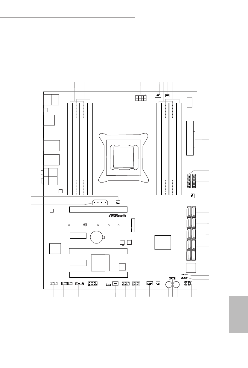
Motherboard Layout
X99 Extreme6/ac
English
1
Intel
X99
ATX12V1
Super
I/O
ATXP WR 1
1
USB3_5_ 6
LAN
LAN
PCIE1
Top:
Central/Bass
Center:
REAR SPK
Top:
LINE IN
Center:
FRONT
Bottom:
Optical
SPDIF
Bottom:
MIC IN
PCIE3
PLED1
1
1
SPEAKER1
HDLED RESET
PLED PWRBTN
PANEL1
1
USB5_6
1
1
USB3_4
COM1
1
1
HD_AUDIO1
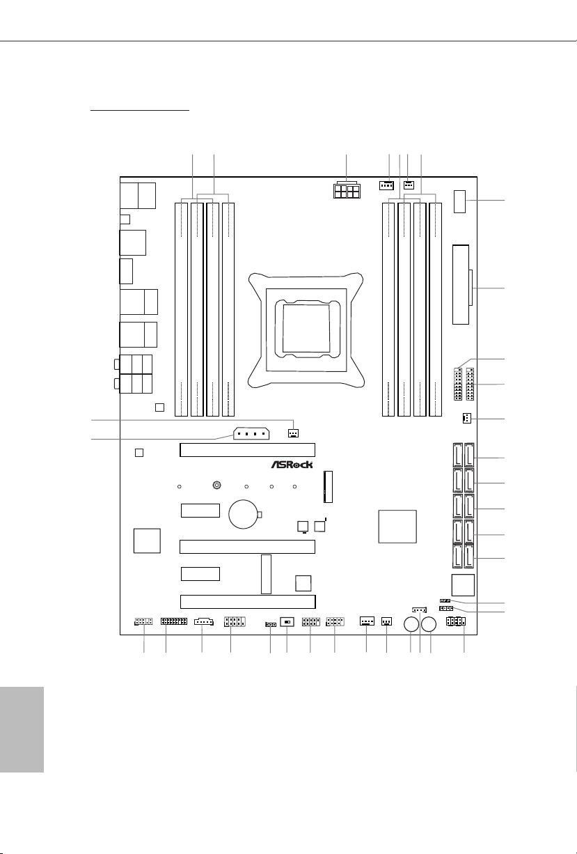
X99 Extreme6
PCIE5
SSATA3_2_ 3
SATA3_0_3
SATA3_1_4
SATA3_2_5
PCIE2
CHA_FAN1
CPU_FAN1
CPU_FAN2
PWR_FAN1
RoHS
9
8
11
10
13
14
15
16
17
22
26
273233
CLRC
BTN1
ESATA1
Top:
RJ-45
USB 3.0
T: USB3
B: USB4
SSATA3_0_ 1
3
4
6
DDR4 _A2 (64 b it, 288 -pin mo dule)
DDR4 _A1 (64 b it, 288 -pin mo dule)
DDR4 _B2 (64 b it, 288 -pin mo dule)
DDR4 _B1 (64 b it, 288 -pin mo dule)
2
1
28
35
Purity
Sound 2
TM
20
Ultra M.2
PCIe Gen3 x4
BIOS_B_LED
128Mb
BIOS
BIOS_B
128Mb
BIOS
BIOS_A
BIOS_A_LED
1
TPMS1
CMOS
Battery
CLRMOS1
1
M2
CT2CT3CT4CT5
T BT1
1
CHA_FAN2
CHA_FAN3
PCIE_PWR1
18
19
29
30
12
34
1
SATA_PWR_1
CT1
DDR4 _D1 (64 b it, 288 -pin mo dule)
DDR4 _D2 (64 b it, 288 -pin mo dule)
DDR4 _C1 (64 b it, 288 -pin mo dule)
DDR4 _C2 (64 b it, 288 -pin mo dule)
7
5
USB 3.0
T: USB1
B: USB2
2011-3 Socket
Vertica l
Type A USB
USB7
1
USB3_7_ 8
Dr.
Debug
Reset Power
21
242325
BIOS_SEL 1
AB
31
PCIE4
MINI_PCIE1
USB 2.0
T: USB1
B: USB2
PS2
Keybo ard
/Mous e
Top:
RJ-45
USB 3.0
T: USB1
B: USB2
English
2
X99 Extreme6

No. Description
1 2 x 288-pin DDR4 DIMM Slots (DDR4_A1, DDR4_B1)
2 2 x 288-pin DDR4 DIMM Slots (DDR4_A2, DDR4_B2)
3 ATX 12V Power Connector (ATX12V1)
4 CPU Fan Connector (CPU_FAN1)
5 2 x 288-pin DDR4 DIMM Slots (DDR4_D2, DDR4_C2)
6 CPU Fan Connector (CPU_FAN2)
7 2 x 288-pin DDR4 DIMM Slots (DDR4_D1, DDR4_C1)
8 Vertical Type A USB 2.0 (USB7)
9 ATX Power Connector (ATXPWR1)
10 USB 3.0 Header (USB3_7_8)
11 USB 3.0 Header (USB3_5_6)
12 Chassis Fan Connector (CHA_FAN3)
13 SATA3 Connectors (SSATA3_0_1)
14 SATA3 Connectors (SSATA3_2_3)
15 SATA3 Connectors (SATA3_0_3)
16 SATA3 Connectors (SATA3_1_4)
17 SATA3 Connectors (SATA3_2_5)
18 Power LED Header (PLED1)
19 Chassis Speaker Header (SPEAKER1)
20 System Panel Header (PANEL1)
21 Power Switch (PWRBTN1)
22 HDD Saver Connector (SATA_PWR_1)
23 Reset Switch (RSTBTN1)
24 Chassis Fan Connector (CHA_FAN2)
25 Chassis Fan Connector (CHA_FAN1)
26 USB 2.0 Header (USB3_4)
27 USB 2.0 Header (USB5_6)
28 BIOS Selection Switch (BIOS_SEL1)
29 Clear CMOS Jumper (CLRCMOS1)
30 COM Port Header (COM1)
31 underbolt AIC Connector (TBT1)
32 TPM Header (TPMS1)
33 Front Panel Audio Header (HD_AUDIO1)
34 PCIe Power Connector (PCIE_PWR1)
35 Power Fan Connector (PWR_FAN1)
X99 Extreme6/ac / X99 Extreme6
English
3
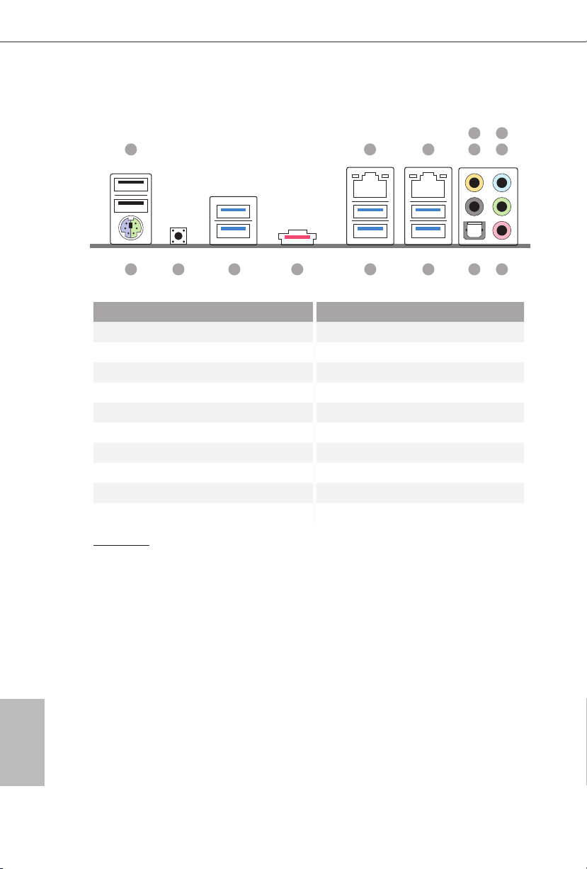
I/O Panel
1
15 891011121314
No. Description No. Description
1 USB 2.0 Ports (USB12) 9 Optical SPDIF Out Port
2 LAN RJ-45 Port 10 USB 3.0 Ports (USB3_34)
(Qualcomm® Atheros® AR8171)* (ASMedia ASM1074 hub)
3 LAN RJ-45 Port 11 USB 3.0 Ports (USB3_12)
(Intel® I218V)* (ASMedia ASM1074 hub)
4 Central / Bass (Orange) 12 eSATA Connector***
5 Rear Speaker (Black) 13 USB 3.0 Ports (USB31_12)
6 Line In (Light Blue) (ASMedia ASM1042)
7 Front Speaker (Lime)** 14 Clear CMOS Switch
8 Microphone (Pink) 15 PS/2 Mouse/Keyboard Port
32 547
6
English
4
CAU TION:
For operating system installation, be sure to plug your USB ash drive into the USB 2.0
Ports (USB12).
X99 Extreme6/ac / X99 Extreme6
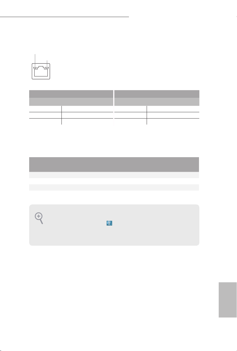
* ere are two LEDs on each LAN port. Ple ase refer to the table below for the LAN port LED indications.
ACT/LINK LED
SPEED LED
LAN Por t
Activity / Link LED Speed LED
Status Description Status Description
O No Link O 10Mbps connection
Blinking Data Activity Orange 100Mbps connection
On Link Green 1Gbps connection
** If you use a 2- channel speaker, please connect the speaker’s plug into “Front Speaker Jack”. See the table below
for connection details in accordance with the type of s peaker you use.
Audio Output
Channels
Front Speaker
(No. 7)
Rear Speaker
(No. 5)
Central / Bass
(No. 4)
2 V -- -- --
4 V V -- --
6 V V V --
8 V V V V
To enable Multi-Streaming, you need to connect a front panel audio cabl e to the front
panel au dio header. Aer restarting your computer, you will nd the “Mixer” tool on your
system. Please selec t “Mixer ToolBox” , click “Enable playback multi-streaming”, and
click “ok”. Choose “2CH”, “4CH”, “6CH”, or “8CH” and then you are allowed to sel ect
“Realtek HDA Primary output” to use the Rear Speaker, Central/Bass, and Front Speaker,
or select “Realtek HDA Audio 2nd output ” to use the front panel audio.
*** e eSATA connector supports SATA with cables within 1 meters. e SSATA3_3 connector is
shared w ith the eSATA port
Line In
(No. 6)
English
5

Chapter 1 Introduction
ank you for purchasing ASRock X99 Extreme6/ac / X99 Extreme6 motherboard,
a reliable motherboard produced under ASRock’s consistently stringent quality
control. It delivers excellent performance with robust design conforming to
ASRock’s commitment to quality and endurance.
Becau se the motherboard specication s and the BIOS soware might be upd ated, the
content of this documentation will be subject to change without notice. In case any modications of this d ocumentation occur, the updated version will be availa ble on ASRock’s
website w ithout further notice . If you require technical support rel ated to this mothe rboard, please v isit our website for specic information about the model you are using. You
may nd the l atest VGA cards and CPU suppor t list on ASRock’s website as well. ASRock
website http://www.asrock.com.
1.1 Package Contents
ASRock X99 Extreme6/ac / X99 Extreme6 Motherboard (ATX Form Factor)
•
ASRock X99 Extreme6/ac / X99 Extreme6 Quick Installation Guide
•
ASRock X99 Extreme6/ac / X99 Extreme6 Support CD
•
1 x I/O Panel Shield
•
1 x ASRock SLI_Bridge_2S Card
•
1 x ASRock 3-Way SLI-2S1S Bridge Card
•
4 x Serial ATA (SATA) Data Cables (Optional)
•
1 x HDD Saver Cable
•
1 x ASRock WiFi 2.4/5GHz Antenna (for X99 Extreme6/ac only)
•
2 x SMA Wi-Fi Antenna Cables (for X99 Extreme6/ac only)
•
1 x Screw for Ultra M.2 Socket
•
1 x Screw for mini-PCIe Slot (for X99 Extreme6 only)
•
English
6

1.2 Specications
Platform
CPU
Chipset
Memory
* Please refer to Memory Support List on ASRock's website for
more information. (http://www.asrock.com/)
X99 Extreme6/ac / X99 Extreme6
ATX Form Factor
•
2oz Copper PCB
•
High Density Glass Fabric PCB
•
Multiple Filter Cap (MFC) (Filter dierent noise by 3
•
dierent capacitors: DIP solid cap, POSCAP and MLCC)
Supports Intel® CoreTM i7 and Xeon® 18-Core Processors
•
Family for the LGA 2011-3 Socket
Digi Power design
•
12 Power Phase design
•
Supports Intel® Turbo Boost 2.0 Technology
•
Supports Untied Overclocking Technology
•
Intel® X99
•
Quad Channel DDR4 Memory Technology
•
8 x DDR4 DIMM Slots
•
Supports DDR4 3000+(OC)*/2933+(OC)/2800(OC)/2400
•
(OC)/2133/1866/ 1600/1333/1066 non-ECC, un-buered
memory
Supports non-ECC RDIMM (Registered DIMM)
•
Supports DDR4 ECC, un-buered memory/RDIMM with
•
Intel® Xeon® processors E5 series in the LGA 2011-3 Socket
Max. capacity of system memory: 128GB (see CAUTION)
•
Supports Intel® Extreme Memory Prole (XMP) 2.0
•
Expansion
Slot
3 x PCI Express 3.0 x16 Slots (PCIE1 @ x16 mode; PCIE3 @
•
x16 mode; PCIE5 @ x8 mode)
* If you install CPU with 28 lanes, PCIE1/PCIE3/PCIE5 will run
at x16/x8/x4.
* If M.2 PCI Express module is installed, PCIE5 will be disabled.
2 x PCI Express 2.0 x1 Slots
•
1 x mini-PCI Express Slot: For WiFi + BT module (for X99
•
Extreme6/ac)
English
7

Audio
LAN
1 x mini-PCI Express Slot (for X99 Extreme6)
•
Supports AMD Quad CrossFireXTM, 3-Way CrossFireXTM
•
and CrossFireXTM
Supports NVIDIA® Quad SLITM, 3-Way SLITM and SLI
•
* If you install CPU with 28 lanes, 3-Way SLITM is not supported.
7.1 CH HD Audio with Content Protection (Realtek
•
ALC1150 Audio Codec)
Premium Blu-ray Audio support
•
Supports Surge Protection (ASRock Full Spike Protection)
•
Supports Purity Sound™ 2
•
- Nichicon Fine Gold Series Audio Caps
- 115dB SNR DAC with Dierential Amplier
- TI® NE5532 Premium Headset Amplier (Supports up to
600 Ohms headsets)
- Direct Drive Technology
- EMI Shielding Cover
- PCB Isolate Shielding
Supports DTS Connect
•
1 x Intel® I218V (Gigabit LAN PHY 10/100/1000 Mb/s)
•
1 x Qualcomm® Atheros® AR8171 (PCIE x1 Gigabit LAN
•
10/100/1000 Mb/s)
Supports Qualcomm® Atheros® Security Wake On Internet
•
Technology (on Qualcomm® Atheros® AR8171)
Supports Wake-On-LAN
•
Supports Lightning/ESD Protection (ASRock Full Spike
•
Protection)
Supports Energy Ecient Ethernet 802.3az
•
Supports PXE
•
TM
English
8
Wireless
LAN
(for X99
Extreme6/
ac only )
Supports IEEE 802.11a/b/g/n/ac
•
Supports Dual-Band (2.4/5 GHz)
•
Supports high speed wireless connections up to 867Mbps
•
2 antennas to support 2 (Transmit) x 2 (Receive) diversity
•
technology
Supports Bluetooth 4.0 / 3.0 + High speed class II
•

Rear Panel
I/O
Storage
X99 Extreme6/ac / X99 Extreme6
1 x PS/2 Mouse/Keyboard Port
•
1 x Optical SPDIF Out Port
•
1 x eSATA Connector
•
2 x USB 2.0 Ports (Supports ESD Protection (ASRock Full
•
Spike Protection))
4 x USB 3.0 Ports (ASMedia ASM1074 hub) (Supports ESD
•
Protection (ASRock Full Spike Protection))
2 x USB 3.0 Ports (ASMedia ASM1042) (Supports ESD
•
Protection (ASRock Full Spike Protection))
2 x RJ-45 LAN Ports with LED (ACT/LINK LED and SPEED
•
LE D)
1 x Clear CMOS Switch
•
HD Audio Jacks: Rear Speaker / Central / Bass / Line in /
•
Front Speaker / Microphone
10 x SATA3 6.0 Gb/s Connectors, support RAID (RAID
•
0, RAID 1, RAID 5, RAID 10 and Intel Rapid Storage 13),
NCQ, AHCI, Hot Plug and ASRock HDD Saver Technology
(SSATA3_3 connector is shared with the eSATA port)
(SSATA3_2 connector is shared with Ultra M.2 Socket)
* RAID is supported on SATA3_0 ~ SATA3_5 ports only.
1 x eSATA Connector, supports NCQ, AHCI and Hot Plug
•
1 x Ultra M.2 Socket, supports M.2 SATA3 6.0 Gb/s module
•
and M.2 PCI Express module up to Gen3 x4 (32 Gb/s)
Connector
1 x COM Port Header
•
1 x TPM Header
•
1 x Power LED Header
•
2 x CPU Fan Connectors (1 x 4-pin, 1 x 3-pin)
•
3 x Chassis Fan Connectors (1 x 4-pin, 2 x 3-pin) (Smart Fan
•
Speed Control)
1 x Power Fan Connector (3-pin)
•
1 x 24 pin ATX Power Connector
•
1 x 8 pin 12V Power Connector (Hi-Density Power
•
Conn ector)
1 x HDD Saver Connector
•
1 x PCIe Power Connector
•
1 x Front Panel Audio Connector
•
English
9

BIOS
Feature
Hardware
Monitor
1 x underbolt AIC Connector
•
2 x USB 2.0 Headers (support 4 USB 2.0 ports) (Supports
•
ESD Protection (ASRock Full Spike Protection))
1 x Vertical Type A USB 2.0
•
2 x USB 3.0 Headers (Support 4 USB 3.0 ports) (Supports
•
ESD Protection (ASRock Full Spike Protection))
1 x Dr. Debug with LED
•
1 x Power Switch with LED
•
1 x Reset Switch with LED
•
1 x BIOS Selection Switch
•
2 x 128Mb AMI UEFI Legal BIOS with multilingual GUI
•
support (1 x Main BIOS and 1 x Backup BIOS)
Supports Secure Backup UEFI Technology
•
ACPI 1.1 Compliant wake up events
•
SMBIOS 2.3.1 Support
•
CPU, DRAM, PCH 1.05V, PCH 1.5V, VPPM Voltage Multi-
•
adjustment
CPU/Chassis temperature sensing
•
CPU/Chassis/Power Fan Tachometer
•
CPU/Chassis Quiet Fan (Auto adjust chassis fan speed by
•
CPU temperature)
CPU/Chassis Fan multi-speed control
•
Voltage monitoring: +12V, +5V, +3.3V, CPU Input Voltage,
•
CPU Internal Voltages
English
10
OS
Certications
Microso® Windows® 10 64-bit / 8.1 32-bit / 8.1 64-bit / 8 32-
•
bit / 8 64-bit / 7 32-bit / 7 64-bit
FCC, CE, WHQL
•
ErP/EuP Ready (ErP/EuP ready power supply is required)
•

X99 Extreme6/ac / X99 Extreme6
* For detailed product infor mation, please vis it our website: http://www.asrock .com
Please realize that there is a certain risk involved with overcl ocking, including adjusting
the setting in the BIOS, applying Untied O verclocking Technology, or using third-party
overclocking tools. Overclocking may aect your system’s stability, or even cause damage to
the components and devices of your system. It should be d one at your own risk and expense.
We are not responsible for possible damage caused by overclocking.
Due to limitation , the actual memory size may be less than 4GB for the reser vation for system usage under Windows® 32-bit operating syste ms. Wind ows® 64- bit operating systems
do not have s uch limitations . You can use ASRo ck XFast RAM to utilize the memor y that
Windows® cannot use.
11
English
1.3 WiFi-802.11ac Module and ASRock WiFi 2.4GHz Antenna
(for X99 Extreme6/ac )
WiFi + BT Module
is motherboard comes with an exclusive WiFi 802.11 a/b/g/n/ac + BT v4.0
module that oers support for WiFi 802.11 a/b/g/n/ac connectivity standards and
Bluetooth v4.0. WiFi + BT module is an easy-to-use wireless local area network
(WLAN) adapter to support WiFi + BT. Bluetooth v4.0 standard features Smart
Ready technology that adds a whole new class of functionality into the mobile
devices including Apple’s most recent iPhone 4S. BT 4.0 also includes Low Energy
Technology and ensures extraordinary low power consumption for PCs. e
2T2R WiFi solution sets a WiFi high speed standard and oers max link rate up to
867Mbps.
* e transmission speed may vary according to the environment.
* e WiFi + BT module is supported under Windows® 8 / 8 64-bit / 7 / 7 64-bit
on ly.
English
12
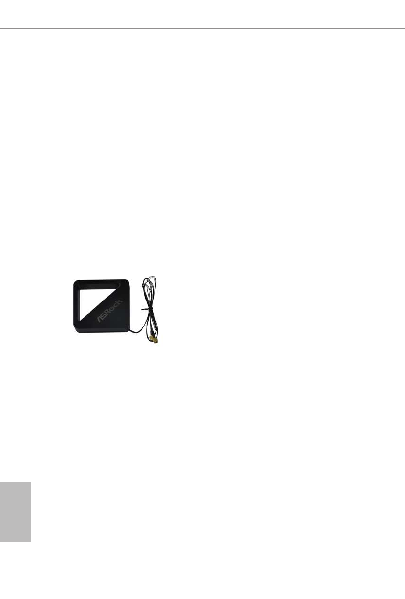
ASRock WiFi 2.4GHz Antenna
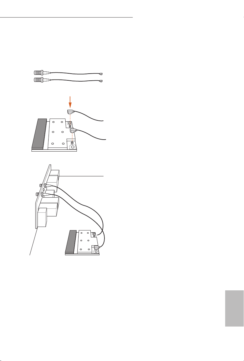
Installing the SMA Wi-Fi Antenna Cables
Step 1
Prepare the SMA Wi-Fi Antenna Cables that
come with the package.
Step 2
Locate the WiFi Module that is installed on the
motherboard's mini-PCIe slot. en attach the
SMA Wi-Fi Antenna Cables to the WiFi Module.
Step3
Insert the RP-SMA Wi-Fi Antenna Connectors
to the antenna ports on the I/O shield
X99 Extreme6/ac / X99 Extreme6
13
English
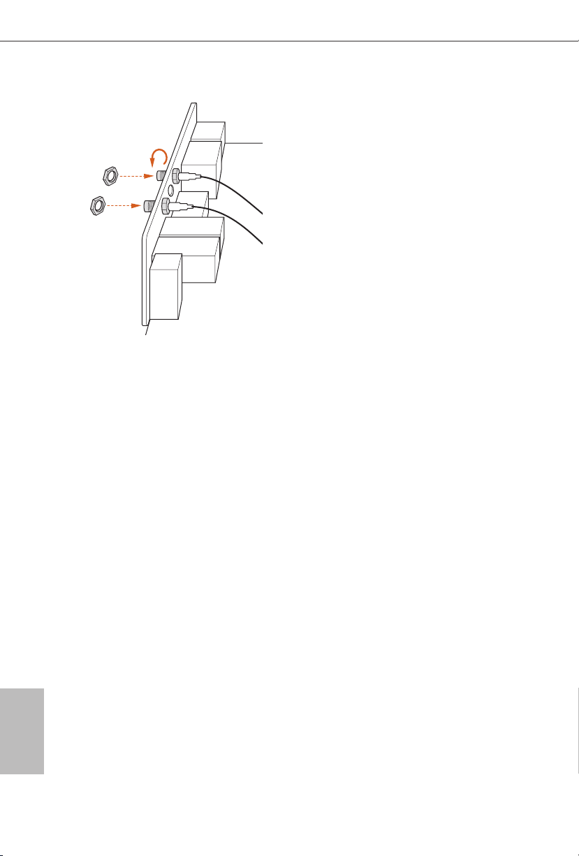
Step 4
Fasten the screw nuts to secure the connectors.
English
14

X99 Extreme6/ac / X99 Extreme6
Chapter 2 Installation
is is an ATX form factor motherboard. Before you install the motherboard, study
the conguration of your chassis to ensure that the motherboard ts into it.
Pre-installation Precautions
Take note of the following precautions before you install motherboard components
or change any motherboard settings.
Make sure to unplug the power cord before installing or removing the motherboard
•
components. Failure to do so may cause physical injuries and damages to motherboard
components.
In order to avoid damage from static electricity to the motherboard’s components,
•
NEVER place your motherboard directly on a carpet. Also remember to use a grounded
wrist strap or touch a safety grounded object before you handle the components.
Hold components by the edges and do not touch the ICs.
•
Whenever you uninstall any components, place them on a grounded anti-static pad or
•
in the bag that comes with the components.
When placing screws to secure the motherboard to the chassis, please do not over-
•
tighten the screws! Doing so may damage the motherboard.
15
English
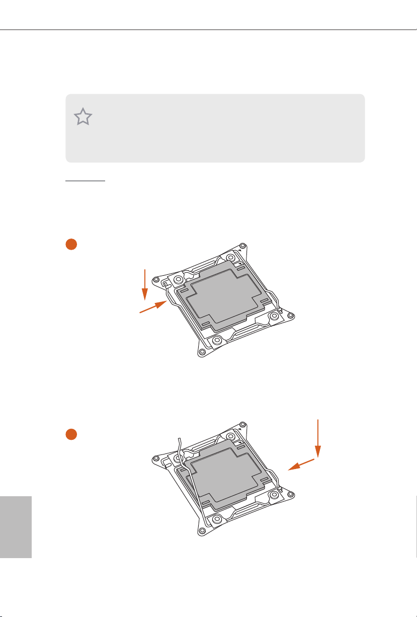
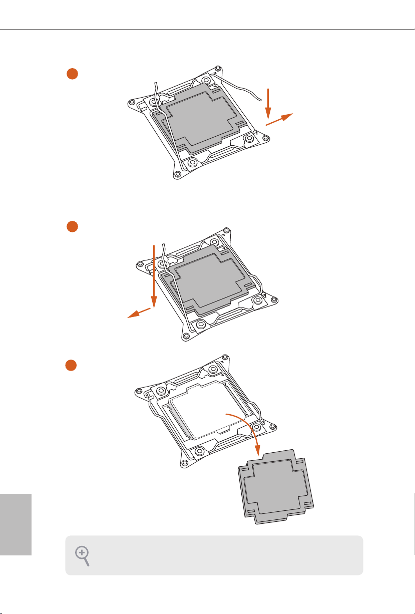
2.1 Installing the CPU
1. Before you insert the 2 011-3-Pin CPU into the socket, please check if the PnP cap i s on
the socket, if the CPU surface is unclean, or if there are any bent pins in the socket . Do
not force to insert the CPU into the socket if above situation is found. Otherwise, the CPU
will be seriously damaged.
2. Unplug all power c ables before ins talling the CPU.
CAU TION:
Please note that X99 platform is only compatible with the LGA 2011-3 socket, which is
incompatible with the LGA 2011 socket (for X79 platform).
1
A
B
English
16
A
2
B

X99 Extreme6/ac / X99 Extreme6
3
4
A
B
5
English
17
6
A
B
7
A
B
English
18
8
Please save and replace the cover if the processor is removed. e cover must be placed if
you wish to return the motherboard for aer service.
X99 Extreme6/ac / X99 Extreme6
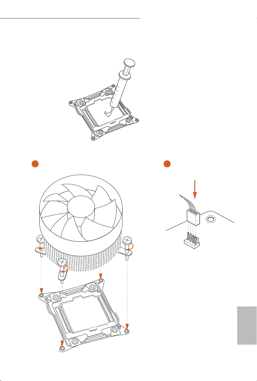
2.2 Installing the CPU Fan and Heatsink
1 2
FAN
CPU_
English
19
2.3 Installation of Memory Modules (DIMM)
is motherboard provides eight 288-pin DDR4 (Double Data Rate 4) DIMM slots, and
supports Quad Channel Memory Technology.
1. For quad chann el conguration, you always need to install identical (the same brand,
speed , size and chip-type) DDR4 DIMM pairs.
2. It is not allowed to instal l a DDR, DDR2 or DDR 3 memory modul e into a DDR4 slot;
otherwise, this motherboard and DIMM may be damaged.
3. e DIMM only ts in one correct orientation . It will cause per manent damage to the
motherboard and the DIMM if you force the DIM M into the slot at incorrect o rientation.
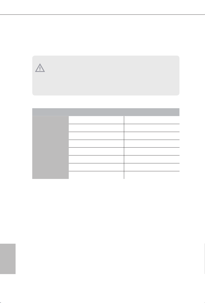
Quad Channel Memory Conguration
Priority 1 2
DDR4_A1
DDR4_A2
DDR4_B1
DDR4_B2
DDR4_C1
DDR4_C2
DDR4_D1
DDR4_D2
Populated Populated
Populated
Populated Populated
Populated
Populated Populated
Populated
Populated Populated
Populated
English
20
Due to Intel® CPU spec denition, please install the memory modules on DDR4_A1,
•
DDR4_B1, DDR4_C1 and DDR4_D1 for rst priority. If the four DDR4 DIMM slots
above are fully installed, and you want to use more than four memory modules, please
install the other memory modules from le to right (from DDR4_A2, DDR4_B2,
DDR4_D2 to DDR4_C2.)
If only two memory modules are installed in the DDR4 DIMM slots, then Dual
•
Channel Memory Technology is activated. If three memory modules are installed, then
Triple Channel Memory Technology is activated. If more than four memory modules
are installed in the DDR4 DIMM slots, then Quad Channel Memory Technology is
activated.
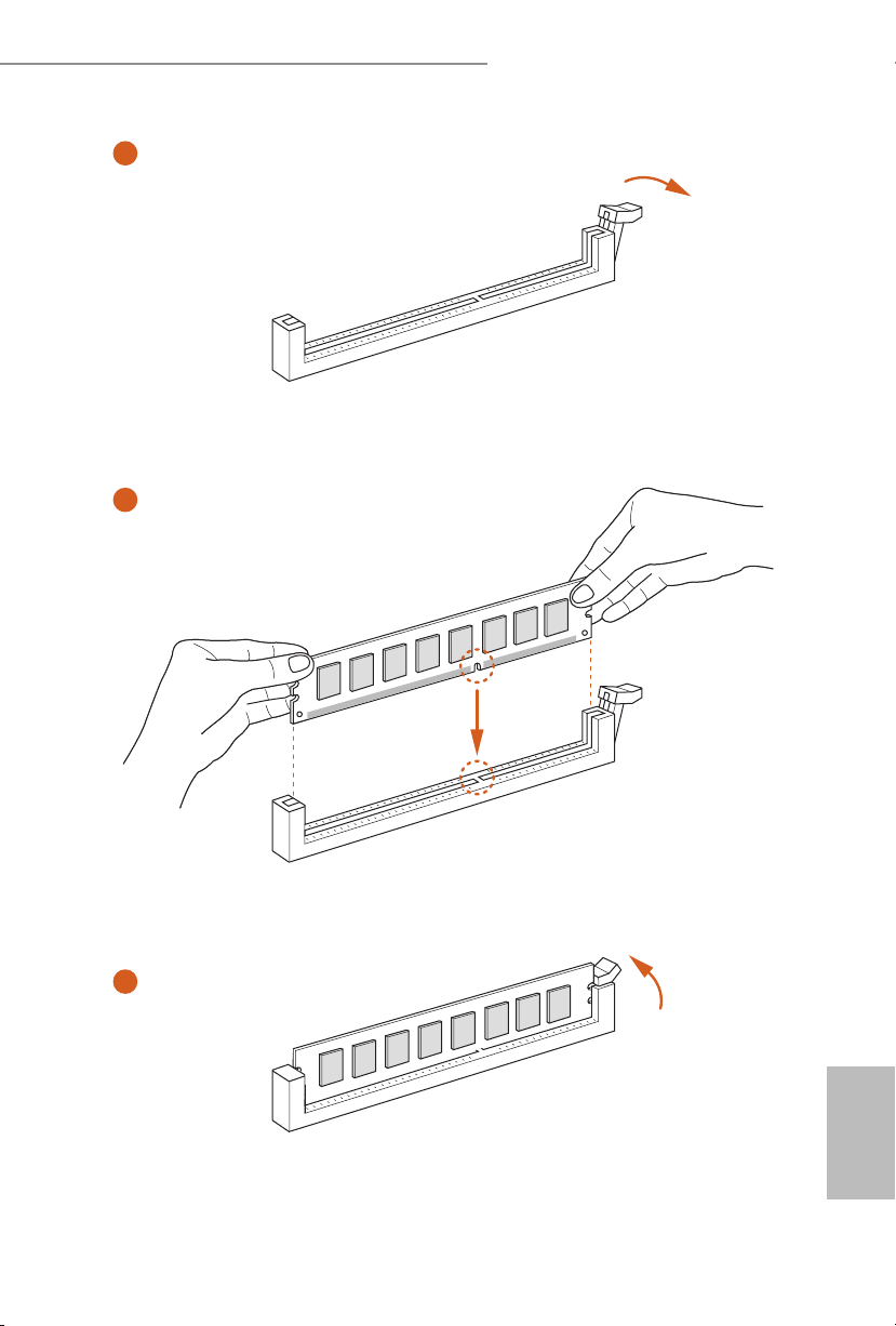
X99 Extreme6/ac / X99 Extreme6
1
2
3
English
21
2.4 Expansion Slots (PCI Express Slots)
ere are 5 PCI Express slots and 1 mini-PCI Express slot on the motherboard.
Before installing an expansion c ard, ple ase make sure that the powe r supply is switched o
or the power cord is unplugged. Please read the documentation of the expansion c ard and
make necessary hardware settings for the card before you start the installation.
PCIe slots:
PCIE1 (PCIe 2.0 x1 slot) is used for PCI Express x1 lane width cards.
PCIE2 (PCIe 3.0 x16 slot) is used for PCI Express x16 lane width graphics cards.
PCIE3 (PCIe 2.0 x1 slot) is used for PCI Express x1 lane width cards.
PCIE4 (PCIe 3.0 x16 slot) is used for PCI Express x8 lane width graphics cards.
PCIE5 (PCIe 2.0 x16 slot) is used for PCI Express x2 lane width graphics cards.
mini-PCIe slot:
MINI_PCIE1 (mini-PCIe slot) is used for WiFi module.
* e mini-PCI Express slot is shared with PCIE3 slot.
PCIe Slot Congurations
PCIE2 PCIE4
Single Graphics Card x16 N/A
English
22
Two Graphics Cards in
CrossFireXTM or SLITM Mode
For a better ther mal environment , please conne ct a chassis fan to the motherboard’s chassis fan connector (CHA_FAN1, CHA_FAN2 or CHA_ FAN3) when using multiple graphic s
cards.
x8 x8
X99 Extreme6/ac / X99 Extreme6
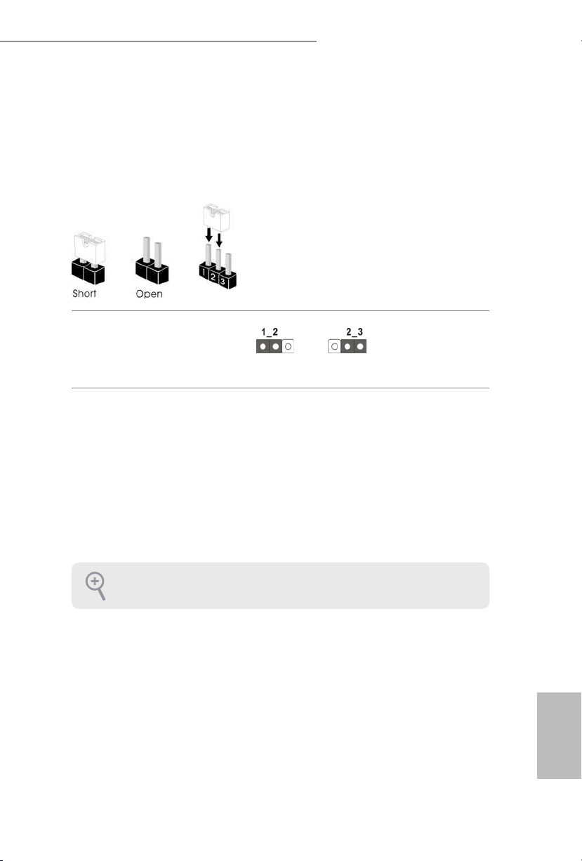
2.5 Jumpers Setup
e illustration shows how jumpers are setup. When the jumper cap is placed on
the pins, the jumper is “Short”. If no jumper cap is placed on the pins, the jumper
is “Open”. e illustration shows a 3-pin jumper whose pin1 and pin2 are “Short”
when a jumper cap is placed on these 2 pins.
Clear CMOS Jumper
(C LRC MO S1)
(see p.1 or p.2, No. 29)
CLRCMOS1 allows you to clear the data in CMOS. To clear and reset the system
parameters to default setup, please turn o the computer and unplug the power
cord from the power supply. Aer waiting for 15 seconds, use a jumper cap to
short pin2 and pin3 on CLRCMOS1 for 5 seconds. However, please do not clear
the CMOS right aer you update the BIOS. If you need to clear the CMOS when
you just nish updating the BIOS, you must boot up the system rst, and then shut
it down before you do the clear-CMOS action. Please be noted that the password,
date, time, and user default prole will be cleared only if the CMOS battery is
removed.
Clear CMOSDefault
e Clear CMOS Switch has the same function as the Clear CMOS jumper.
English
23
2.6 Onboard Headers and Connectors
1
1
PLED+
PLED+
PLED-
Onboard headers and connectors are NOT jumpers. Do NOT pla ce jumper caps over these
heade rs and connectors. Plac ing jumper caps over the hea ders and connectors will cause
permanent damage to the motherboard.
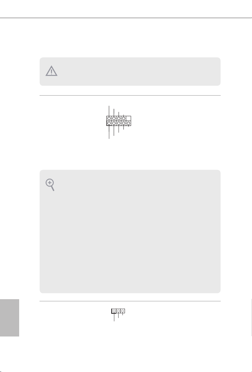
System Panel Header
(9-p in PA NEL1)
(see p.1 or p.2, No. 20)
PWRBTN (Power Swi tch):
Connec t to the power switch on the chassis f ront panel. You may congure the way to turn
o your system using the powe r switch .
RESET (Reset Sw itch):
Connec t to the reset switch on the chassis f ront panel. Pre ss the reset switch to restart the
computer if the computer freezes and fails to perform a normal restart.
PLED (Syste m Power LED):
Connec t to the power status indicator on the chassi s front panel. e LED is on when the
system is operating. e LED keeps blinking when the system i s in S1/S3 sleep state . e
LED is o when the system is in S4 sleep state or powered o (S5).
HDLED (Ha rd Drive Activity LED):
Connec t to the hard drive ac tivity LED on the chassis f ront panel. e LED is on when the
hard drive is reading or writing data .
e front panel design may dier by chassis . A front panel module mainly consists of powe r
switch, reset switch, power LED, hard drive a ctivity LED, speaker and etc. W hen connecting your ch assis front panel module to this header, make sure the wire assig nments and the
pin assignments are matched correctly.
PLED+
PLED-
HDLED-
HDLED+
PWRBTN#
GND
GND
RESET#
GND
Connect the power
switch, reset switch and
system status indicator on
the chassis to this header
according to the pin
assignments below. Note
the positive and negative
pins before connecting
the cables.
English
24
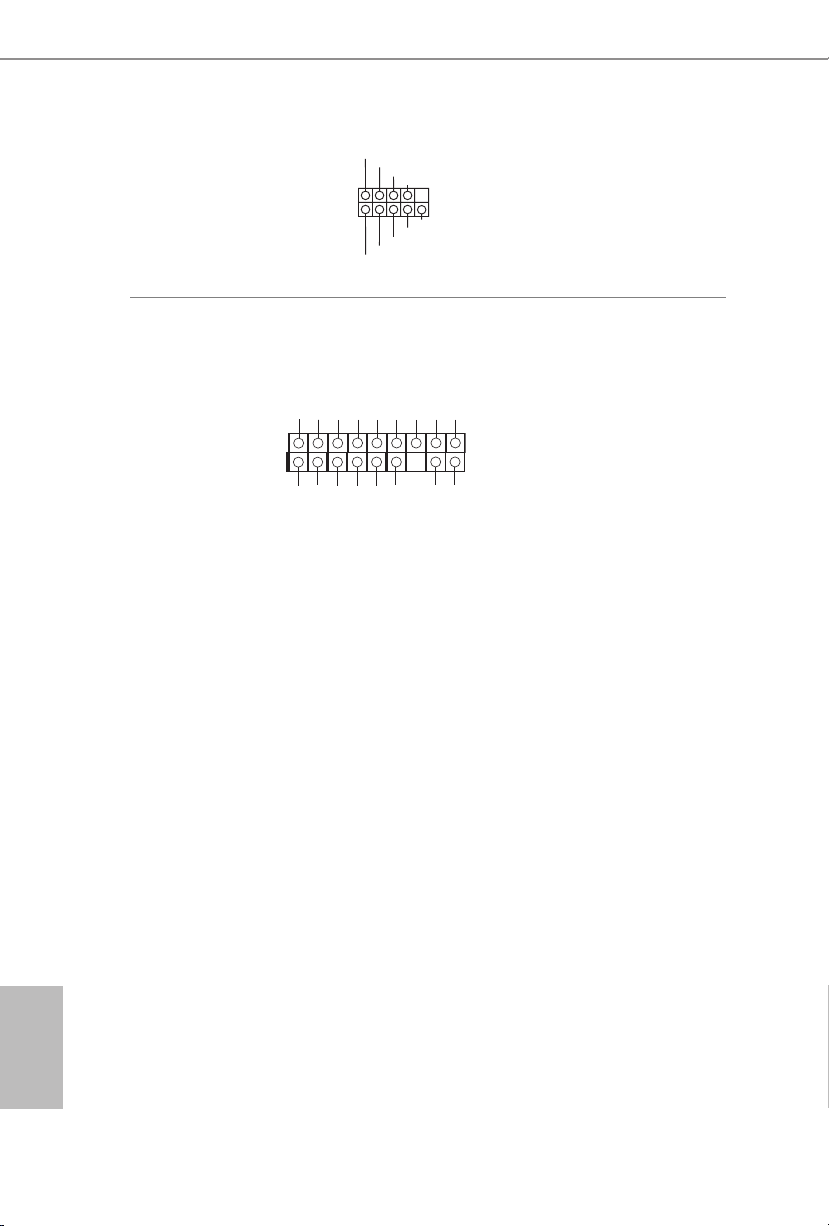
Power LED Header
(3-pin PLE D1)
(see p.1 or p.2, No. 18)
Please connect the chassis
power LED to this header
to
indicate the system’s
power status.
X99 Extreme6/ac / X99 Extreme6
DUMMY
GND
GND
P+
P-
USB_PWR
P+
P-
USB_PWR
1
1
Serial ATA3 Connectors
(SSATA3_0_1:
see p.1 or p.2, No. 13)
(SSATA3_2_3:
see p.1 or p.2, No. 14)
(SATA3_0_ 3:
see p.1 or p.2, No. 15)
(SATA3_1_4:
see p.1 or p.2, No. 16)
(SATA3_2_5:
see p.1 or p.2, No. 17)
USB 2.0 Headers
(9-pin USB3_4)
(see p.1 or p.2, No. 26)
(9-pin USB5_6)
(see p.1 or p.2, No. 27)
SSATA3_0
SSATA3_2
SATA3_0
SATA3_1
SATA3_2
SSATA3_1
SSATA3_3
SATA3_3
SATA3_4
SATA3_5
ese ten SATA3
connectors support SATA
data cables for internal
storage devices with up
to 6.0 Gb/s data transfer
rate. If the eSATA port
on the rear I/O has been
connected, the internal
SSATA3_3 will not
function. If the Ultra M.2
Socket has been occupied,
the internal SSATA3_2
will not function.
* RAID is supported on
SATA3_0 ~ SATA3_5
ports only.
Besides two USB 2.0 ports
on the I/O panel, there
are two headers and one
port on this motherboard.
Each USB 2.0 header can
support two ports.
(USB7)
(see p.1 or p.2, No. 8)
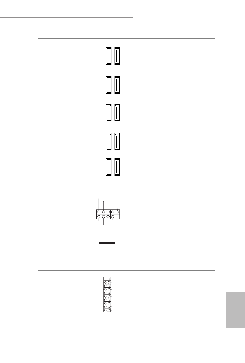
USB 3.0 Headers
(19-pin USB3_5_6)
(see p.1 or p.2, No. 11)
(19-pin USB3_7_8)
(see p.1 or p.2, No. 10)
IntA_PA_SSRX-
IntA_PA_SSRX+
IntA_PA_SSTX-
IntA_PA_SSTX+
IntA_PA_D-
IntA_PA_D+
Vbus
GND
GND
VbusVbus
IntA_PB_SSRX-
IntA_PB_SSRX+
GND
IntA_PB_SSTX-
IntA_PB_SSTX+
GND
IntA_PB_D-
IntA_PB_D+
Dummy
Besides six USB 3.0 ports
on the I/O panel, there
are two headers on this
motherboard. Each USB
3.0 header can support
two ports.
English
25
Front Panel Audio Header
J_SENSE
OUT2_L
1
MIC_RET
PRESENCE#
GND
OUT2_R
MIC2_R
MIC2_L
OUT_RET
1
DUMMY
SPEAKER
GND
N_SPEED
FAN_VOLTAG
CHA_FAN_SPEED
(9-pin HD_AUDIO1)
(see p.1 or p.2, No. 33)
is header is for
connecting audio devices
to the front audio panel.
1. High Denition Audio supports Ja ck Sens ing, but the panel wire on the chassis must support HDA to function correctly. Please follow the instructions in our manual and chassi s
manual to instal l your system.
2. If you use an AC’97 audio panel , please install it to the f ront panel audio header b y the
steps below:
A. Connect Mic_ IN (MIC) to MIC2_ L.
B. Conne ct Audio_R (RIN) to OUT2 _R and Audio_ L (LIN) to OUT2_ L.
C. Connect Ground (GND) to Ground (GND).
D. MIC_ RET and OUT_RET are for the HD audio panel only. You don’t need to connect
them for the AC’97 audio panel.
E. To activate the front mic, go to the “FrontMic” Tab in the Realtek Control panel and
adjust “Recording Volume”.
English
26
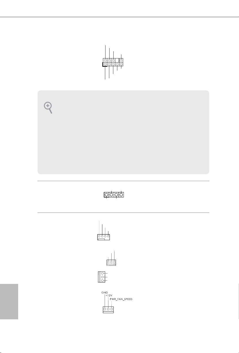
Chassis Speaker Header
(4-pin SPE AKER 1)
(see p.1 or p.2, No. 19)
Chassis and Power Fan
Connectors
(4-pin CHA_FAN1)
(see p.1 or p.2, No. 25)
(3-pi n C HA_FA N2)
(see p.1 or p.2, No. 24)
(3-pi n C HA_FA N3)
(see p.1 or p.2, No. 12)
(3-pin PWR_FAN1)
(see p.1 or p.2, No. 35)
+5V
+12V
CHA_FAN_SPEED
FAN_SPEED_CONTROL
E
GND
GND
FAN_VOLTAGE
CHA_FA
DUMMY
Please connect the chassis
speaker to this header.
Please connect fan cables
to the fan connectors and
match the black wire to
the ground pin. CHA_
FAN fan speed can be
controlled through UEFI
or A-Tuning .
X99 Extreme6/ac / X99 Extreme6
CPU_FAN_SPEED
FAN_SPEED_CONTROL
4 3 2 1
4 1
8 5
1
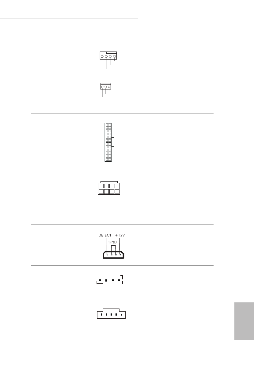
CPU Fan Connectors
(4-pin CPU_FAN1)
(see p.1 or p.2, No. 4)
(3-pin CPU_FAN2)
(see p.1 or p.2, No. 6)
ATX Power Connector
(24-pin AT XPWR 1)
(see p.1 or p.2, No. 9)
ATX 12V Power
Connector
(8-pin ATX12V1)
(see p.1 or p.2, No. 3)
12
1
GND
+12V
CPU_F
AN_SPEED
GND
FAN_VOLTAGE
24
13
is motherboard provides a 4-Pin CPU fan
(Quiet Fan) connector.
If you plan to connect a
3-Pin CPU fan, please
connect it to Pin 1-3.
is motherboard provides a 24-pin ATX power
connector. To use a 20-pin
ATX power supply, please
plug it along Pin 1 and Pin
13.
is motherboard provides an 8-pin ATX 12V
power connector. To use a
4-pin ATX power supply,
please plug it along Pin 1
and Pin 5.
PCIe Power Connector
(4-pin PCIE _PWR1)
(see p.1 or p.2, No. 34)
HDD Saver Connector
(4-pin SATA _PWR_1)
(see p.1 or p.2, No. 22)
underbolt AIC
Connector
(5-pin T BT1)
(see p.1 or p.2, No. 31)
Please connect a 4 pin molex
power cable to this connector
when more than three graphics
cards are installed.
Please connect the HDD Saver
Cable to this connector to
manage the power state of HDD.
Please connect a underbolt™
add-in card (AIC) to this
connector via the GPIO cable.
English
27
Serial Port Header
1
1
(9-pin COM1)
(see p.1 or p.2, No. 30)
RRXD1
DDTR#1
TTXD1
DDCD#1
DDSR#1
CCTS#1
RRTS#1
GND
RRI#1
is COM1 header
supports a serial port
module.
TPM Header
(17-pi n TPMS1)
(see p.1 or p.2, No. 32)
is connector supports Trusted
Platform Module (TPM) system,
which can securely store keys,
D
SMB _C LK_ MAI N
SMB _D ATA _MA IN
LAD 2
GN D
GN D
LAD 1
S_P WR DWN #
SER IR Q #
digital certicates, passwords,
GN
and data. A TPM system also
helps enhance network security,
protects digital identities, and
+3 V
LAD 3
LAD 0
FRA M E
PC IC LK
PC IR ST #
+3 VS B
ensures platform integrity.
GN D
English
28
 Loading...