


Contact Information
If you need to contact ASRock or want to k now more about ASRock, you’re welcome
to visit ASRock’s website at http://www.asrock.com; or you may contact your dealer
for further information. For technical questions, please submit a support request
form at https://event.asrock.com/tsd.asp
ASRock Incorporation
e-mail: info@asrock.com.tw
ASRock EUROPE B.V.
e-mail: sales@asrock.nl
ASRock America, Inc.
e-mail: sales@asrockamerica.com
Scan the QR code to view more manuals and documents.

Contents
Chapter 1 Introduction 1
1.1 Package Contents 1
1.2 Specications 2
1.3 Motherboard Layout 7
1.4 I/O Panel 9
1.5 Block Diagram 11
1.6 802.11ax Wi-Fi 6E Module and ASRock WiFi 2.4/5/6 GHz
Antenna 12
1.7 Graphics Card Holder 13
Chapter 2 Installation 14
2.1 Installing the CPU 15
2.2 Installing the CPU Fan and Heatsink 18
2.3 Installing Memory Modules (DIMM)
2.4 Connecting the Front Panel Header 29
2.5 Installing the Motherboard 30
2.6 Installing SATA Drives 31
2.7 Installing a Graphics Card 33
2.8 Connecting Peripheral Devices 35
2.9 Connecting the Power Connectors 36
2.10 Power On 37
2.11 Jumpers Setup 38
27

2.12 Onboard Headers and Connectors 39
2.13 Smart Switches 55
2.14 Post Status Checker 57
2.15 M.2 SSD Module Installation Guide (M2_1) 58
2.16 M.2 SSD Module Installation Guide (M2_2) 61
2.17 M.2 SSD Module Installation Guide (M2_3 and M2_5) 63
2.18 M.2 SSD Module Installation Guide (M2_4) 66

Chapter 1 Introduction
ank you for purchasing ASRock X670E Pro RS motherboard, a reliable
motherboard produced under ASRock’s consistently stringent quality control.
It delivers excellent performance with robust design conforming to ASRock’s
commitment to quality and endurance.
Becau se the motherboard specications and the BIOS soware mig ht be updated, the
content of this documentation will be subject to change without notice. In ca se any modications of thi s documentation occur, the updated version wil l be avail able on ASRock’s
website w ithout further notice. If you require technical support rel ated to this motherboard, please visit our webs ite for specic information about the model you are using. You
may nd the l atest VGA cards and CPU support list on ASRock’s website as well. ASRock
website http://www.asrock.com.
1.1 Package Contents
ASRock X670E Pro RS Motherboard (ATX Form Factor)
•
ASRock X670E Pro RS User Manual
•
2 x Serial ATA (SATA) Data Cables (Optional)
•
1 x Graphics Card Holder (Optional)
•
1 x ASRock WiFi 2.4/5/6 GHz Antenna (Optional)
•
4 x Screws for M.2 Sockets (Optional)
•
X670E Pro RS
1

1.2 Specications
Platform
CPU
Chipset
Memory
•
•
•
•
•
•
•
•
•
* Please refer to Memory Support List on ASRock 's website for
more information. (http://www.asrock.com/)
ATX Form Factor
8 Layer PCB
Supports AMD AM5 Socket RyzenTM 7000 Series Desktop
Processors
AMD X670
Dual Channel DDR5 Memory Technology
4 x DDR5 DIMM Slots
Supports DDR5 ECC/non-ECC, un-buered memory up to
6600+(OC)*
Max. capacity of system memory: 128GB
Supports Extreme Memory Prole (X MP) and EXTended
Proles for Overclocking (EXPO) memory modules
Expansion
Slot
Graphics
Audio
CPU:
1 x PCIe 5.0 x16 Slot (PCIE1), supports x16 mode*
•
Chipset:
2 x PCIe 4.0 x1 Slots (PCIE2 and PCIE3)*
•
1 x M.2 Socket (Key E), supports type 2230 WiFi/BT PCIe
•
WiFi module
* Supports NVMe SSD as boot disks
15μ Gold Contact in VGA PCIe Slot (PCIE1)
•
Integrated AMD RDNATM 2 graphics (Actual support may
•
vary by CPU)
1 x HDMI 2.1 TMDS Compatible, supports HDR, HDCP 2.3
•
and max. resolution up to 4K 60Hz
1 x DisplayPort 1.4 with DSC (compressed), supports HDCP
•
2.3 and max. resolution up to 4K 120Hz
7.1 CH HD Audio (Realtek ALC897 Audio Codec)
•
Nahimic Audio
•
2

LAN
Wireless
LAN
2.5 Gigabit LAN 10/100/1000/2500 Mb/s
•
Dragon RTL8125BG
•
Supports Dragon 2.5G LAN Soware
•
- Smart Auto Adjust Bandwidth Control
- Visual User Friendly UI
- Visual Network Usage Statistics
- Optimized Default Setting for Game, Browser, and
Streaming Modes
- User Customized Priority Control
802.11ax Wi-Fi 6E Module
•
Supports IEEE 802.11a/b/g/n/ac/ax
•
Supports Dual-Band 2x2 with extended 6GHz band* sup-
•
port
* Wi-Fi 6E (6GHz band) will be supported by Microso®
Windows® 11. e availability will depend on the dierent
regulation status of each country and region. It will be activated
(for supported countries) through Windows Update and so-
ware updates once available.
* A 6GHz compatible router is required for 6E functionality.
2 antennas to support 2 (Transmit) x 2 (Receive) diversity
•
technolog y
Supports Bluetooth + High speed class II
•
Supports MU-MIMO
•
X670E Pro RS
USB
1 x USB 3.2 Gen2x2 Type-C (Front)
•
1 x USB 3.2 Gen2 Type-C (Rear)
•
1 x USB 3.2 Gen2 Type-A (Rear)
•
8 x USB 3.2 Gen1 (4 Rear, 4 Front)
•
8 x USB 2.0 (4 Rear, 4 Front)
•
* All USB ports support ESD Protection
3

Rear Panel
I/O
2 x Antenna Ports
•
1 x HDMI Port
•
1 x DisplayPort 1.4
•
1 x Optical SPDIF Out Port
•
1 x USB 3.2 Gen2 Type-A Port (10 Gb/s) (ReDriver)
•
1 x USB 3.2 Gen2 Type-C Port (10 Gb/s) (ReDriver)
•
4 x USB 3.2 Gen1 Ports
•
4 x USB 2.0 Ports
•
1 x RJ-45 LAN Port
•
1 x BIOS Flashback Button
•
1 x Line Out Jack (Gold Audio Jack)
•
1 x Microphone Input Jack (Gold Audio Jack)
•
Storage
RAID
CPU:
1 x Blazing M.2 Socket (M2_1, Key M), supports type 2280
•
PCIe Gen5x4 (128 Gb/s) mode*
1 x Hyper M.2 Socket (M2_2, Key M), supports ty pe
•
2260/2280 PCIe Gen4x4 (64 Gb/s) mode*
Chipset:
1 x Hyper M.2 Socket (M2_3, Key M), supports type
•
2260/2280 PCIe Gen4x4 (64 Gb/s) mode*
1 x M.2 Socket (M2_4, Key M), supports type
•
2242/2260/2280 SATA3 6.0 Gb/s & PCIe Gen3x2 (16 Gb/s)
modes*
1 x Hyper M.2 Socket (M2_5, Key M), supports type
•
2260/2280 PCIe Gen4x4 (64 Gb/s) mode*
6 x SATA3 6.0 Gb/s Connectors
•
* Supports NVMe SSD as boot disks
* Supports ASRock U.2 Kit
Supports RAID 0, RAID 1 and RAID 10 for SATA storage
•
devices
Supports RAID 0, RAID 1 and RAID 10 for M.2 NVMe
•
storage devices
4

Connector
1 x SPI TPM Header
•
1 x Power LED and Speaker Header
•
1 x RGB LED Header*
•
3 x Addressable LED Headers**
•
1 x CPU Fan Connector (4-pin)***
•
1 x CPU/Water Pump Fan Connector (4-pin) (Smart Fan
•
Speed Control)****
4 x Chassis/Water Pump Fan Connectors (4-pin) (Smart Fan
•
Speed Control)*****
1 x 24 pin ATX Power Connector (Hi-Density Power
•
Connect or)
1 x 8 pin 12V Power Connector (Hi-Density Power
•
Connect or)
1 x 4 pin 12V Power Connector (Hi-Density Power
•
Connect or)
1 x Front Panel Audio Connector
•
2 x USB 2.0 Headers (Support 4 USB 2.0 ports)
•
2 x USB 3.2 Gen1 Headers (Support 4 USB 3.2 Gen1 ports)
•
1 x Front Panel Type C USB 3.2 Gen2x2 Header (20 Gb/s)
•
* Supports in total up to 12V/3A, 36W LED Strip
** Support in total up to 5V/3A, 15W LED Strip
*** CPU_FAN1 supports the fan power up to 1A (12W).
**** CPU_FAN2/WP supports the fan power up to 2A (24W).
***** CHA_FAN1~4/WP support the fan power up to 2A (24W).
***** CPU_FAN2/WP and CHA_FAN1~4/WP can auto detect
if 3-pin or 4-pin fan is in use.
X670E Pro RS
BIOS
Feature
OS
Certications
AMI UEFI Legal BIOS with GUI support
•
Microso® Windows® 10 64-bit / 11 64-bit
•
FCC, CE
•
ErP/EuP ready (ErP/EuP ready power supply is required)
•
5

* For detailed product information, please visit our website: http://www.asrock .com
Please realiz e that there is a certain risk involved with overclocking, including adjusting
the setting in the BIOS, applying Untied Overclocking Technol ogy, or using third-party
overclocking tools. Overclocking may aect your system’s stability, or even cause damage to
the components and devices of your system. It should be done at your own r isk and expense.
We are not responsible for pos sible damage caused by overclocking.
6
PCIE1
USB 3.2 Gen1
T: USB32_4
B: USB32_5
HDLED RESET
PLED PWRBTN
PANEL1
1
SPK_PLED1
10
12
16
17
USB_5_6
1
USB_7_8
1
1
CPU_FAN1
11
CPU_FAN2/WP
USB32_ 6_7
1
BIOS
ROM
ATX12V1
ATX12V2
Top:
RJ-45
AMD
X670
USB32_TC_2
2
AMD
X670
ATXP WR 1
4
3
DDR5 _A2 (64 b it, 288 -pin mo dule)
DDR5 _A1 (64 b it, 288 -pin mo dule)
DDR5 _B2 (64 b it, 288 -pin mo dule)
DDR5 _B1 (64 b it, 288 -pin mo dule)
1
18
6
SATA3_4
SATA3_3
SATA3_6
SATA3_5
CHA_FAN3
/WP1
CHA_FAN2
/WP1
ADDR_LED1
1
1
USB32_8_9
CLR
CMOS1
1
CHA_FAN1
/WP
AUDIO
CODEC
LAN
CT1
M2_2
CT3
CT4
M2_1
19
20
23 212225
26
2728
Top:
MIC IN
Center :
Line Out
Bottom :
Optica l
SPDIF
1
ADDR_L ED31ADDR_L ED2
7
8
5
1
SPI_TPM_J1
M2_5
CT11
CT12
M2_3
CT9
CT10
RoHS
CT7
CMOS
Battery
SATA3_2
SATA3_1
15
14
CHA_FAN4
/WP1
24
RGB_LED1
1
1
HD_AUDIO1
13
PCIE3
PCIE2
DRAM
VGA
CPU
BOOT
9
BIOS
_FB1
HDMI 1
DP1
29
USB 3.2 Gen2
T:USB32_3
B: USB32_TC_1
USB 3.2 Gen1
T:USB32_1
B: USB32_2
USB 2.0
USB_2
USB 2.0
USB_1
USB 2.0
USB_4
USB 2.0
USB_3
M2_ WIFI1
WiFi-802.11ax
Module
M2_4
CT6
CT5
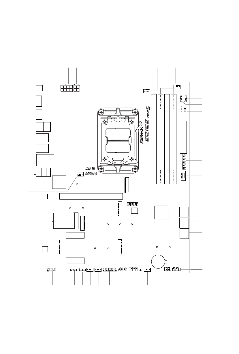
1.3 Motherboard Layout
X670E Pro RS
7

No. Description
1 8 pin 12V Power Connector (ATX12V1)
2 4 pin 12V Power Connector (ATX12V2)
3 CPU Fan Connector (CPU_FAN1)
4 2 x 288-pin DDR5 DIMM Slots (DDR5_A1, DDR5_B1)
5 2 x 288-pin DDR5 DIMM Slots (DDR5_A2, DDR5_B2)
6 CPU/Water Pump Fan Connector (CPU_FAN2/WP)
7 Addressable LED Header (ADDR_LED3)
8 Addressable LED Header (ADDR_LED2)
9 Post Status Checker (PSC)
10 ATX Power Connector (ATXPWR1)
11 USB 3.2 Gen1 Header (USB32_6_7)
12 Front Panel Type C USB 3.2 Gen2x2 Header (USB32_TC_2)
13 SPI TPM Header (SPI_TPM_J1)
14 SATA3 Connectors (SATA3_6)(Upper), (SATA3_5)(Lower)
15 SATA3 Connectors (SATA3_4)(Upper), (SATA3_ 3)(Lower)
16 SATA3 Connectors (SATA3_2)(Upper), (SATA3_1)(Lower)
17 System Panel Header (PANEL1)
18 Power LED and Speaker Header (SPK_PLED1)
19 Chassis/Water Pump Fan Connector (CHA _FAN1/WP)
20 Clear CMOS Jumper (CLRCMOS1)
21 USB 2.0 Header (USB_5_6)
22 USB 2.0 Header (USB_7_8)
23 USB 3.2 Gen1 Header (USB32_8_9)
24 Chassis/Water Pump Fan Connector (CHA_FAN4/WP)
25 Chassis/Water Pump Fan Connector (CHA_FAN3/WP)
26 Addressable LED Header (ADDR_LED1)
27 RGB LED Header (RGB_LED1)
28 Front Panel Audio Header (HD_AUDIO1)
29 Chassis/Water Pump Fan Connector (CHA_FAN2/WP)
8

1.4 I/O Panel
X670E Pro RS
3
21 1
4
12 11
13
No. Description No. Description
1 Antenna Ports 8 USB 3.2 Gen2 Type-C Port
2 2.5G LAN RJ-45 Port* (USB32_TC_1)
3 Microphone Input Jack** 9 USB 3.2 Gen1 Type-A Ports
4 Line Out Jack** (USB32_12)
5 Optical SPDIF Out Port 10 USB 2.0 Ports (USB_1234)
6 USB 3.2 Gen1 Type-A Ports 11 HDMI Port
(USB32_45) 12 DisplayPort 1.4
7 USB 3.2 Gen2 Type-A Port 13 BIOS Flashback Button
(USB32_3)
10 9
7
8
56
9
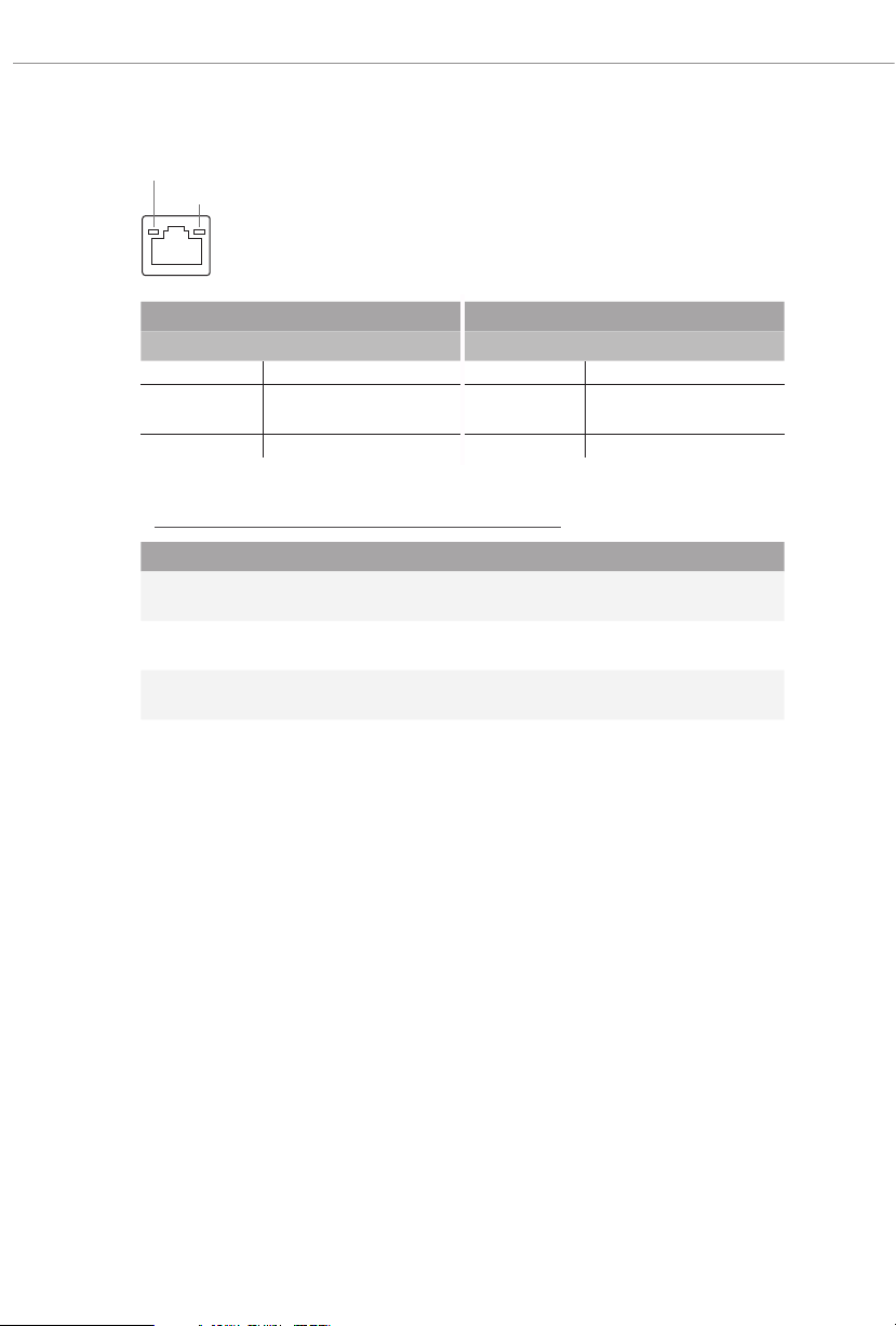
*ere are two LED s on each LAN port. Please re fer to the table below for the LAN port LED indication s.
ACT/LINK LED
SPEED LED
LAN Por t
Activity / Link LED Speed LED
Status Description Status Description
O No Link O 10Mbps connection
Blinking Data Activity Orange
100Mbps/1Gbps
connection
On Link Green 2.5Gbps connection
** Function of the Audio Ports in 2 , 4, 5.1 or 7.1-channel Co nguration :
Channel Port Function
2ch
4ch
5.1ch
7.1c h
Line Out Jack
(Rear Panel)
Pink-Mic
(Front Panel)
Microphone Input Jack
(Rear Panel)
Lime-Headphone
(Front Panel)
Front speaker out
Rear speaker out
Central/Subwoofer speaker out
Side Speaker out
10

1.5 Block Diagram
Flash ROM
PCIe1 Gen5x16 Slot
x16 Gen5
M2_2(PCIe x4)
M2_1(PCIe x4)
x4 Gen5
SPI
x4 Gen4
X670E Pro RS
SIO NCT6796D-S
eSPI
SATA 4 ports
M2_5(PCIe x4)
x4 Gen4
SATA 6Gb
M2_4 (PCIe x2 Gen3/SATA)
M2_3(PCIe x4)
SATA 2 ports
PCIe2 Gen4x1 Slot
x2 Gen3
x4 Gen4
SATA 6Gb
x1 GEN4
Key E WiFi
Realtek RTL8125BG 2.5G LAN
PCIe3 Gen4x1 Slot
x1
x1
x1 GEN4
PCIe x4 Gen4 BUS
1st
AMD PROM21
5Gb/s
Rear USB3.2 GEN1 1 port(LAN UP)
Chipset
5Gb/s
5Gb/s
Front USB3.2 GEN1 2 ports
Rear USB3.2 GEN1 1 port
AMD AM5
Processor
LGA1718
Channel B
Channel A
DP0
DP1
DDR5 Slot x2
DDR5 Slot x2
HDMI Port
DP Port
5Gb/s
AZ(HD Audio)
10Gb/s
Audio Codec ALC897-VB2
Rear USB3.2 GEN2 Type A+C
Rear USB3.2 GEN1 port(LAN down)
2+1
Audio
20Gb/s
Front USB3.2 Gen2X2 Type C
PCIe x4 Gen4 BUS
2nd
AMD PROM21
Chipset
480Mb/s
480Mb/s
Front USB2.0 2 ports
Rear USB2.0 4 ports
the down port support Flash Back
480Mb/s
5Gb/s
5Gb/s
Front USB3.2 GEN1 2 ports
Front USB2.0 2 ports
Rear USB3.2 GEN1 1 port
11
1.6 802.11ax Wi-Fi 6E Module and ASRock WiFi 2.4/5/6 GHz
Antenna
802.11ax Wi-Fi 6E + BT Module
is motherboard comes with an exclusive 802.11 a/b/g/n/ac/ax Wi-Fi 6E + BT module
that oers support for 802.11 a/b/g/n/ac/ax Wi-Fi 6E connectivity standards and
Bluetooth. Wi-Fi 6E + BT module is an easy-to-use wireless local area network (WLAN)
adapter to support Wi-Fi 6E + BT. Bluetooth standard features Smart Ready technology
that adds a whole new class of functionality into the mobile devices. BT also includes
Low Energy Technology and ensures extraordinary low power consumption for PCs.
* e transmission speed may vary according to the environment.
* Wi-Fi 6E (6GHz band) will be supported by Microso® Windows® 11. e availability
will depend on the dierent regulation status of each country and region. It will be
activated (for supported countries) through Windows Update and soware updates
once available.
* A 6GHz compatible router is required for 6E functionality.
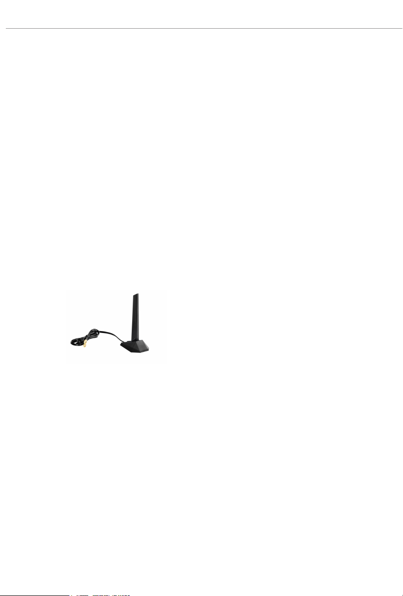
ASRock WiFi 2.4/5/6 GHz Antenna
12

1.7 Graphics Card Holder
Installing the Graphics Card Holder
Before installing the Graphic s Card Holder , please make sure that your motherboard is
properly installed into a PC ca se.
Type A Ty pe B
X670E Pro RS
Step 1
Secure the Graphics Card Holder to the chassis
with 2 screws.
*ere are two types of screws in the package.
Please use the appropriate ty pe based on the
standos on the motherboard tray of your PC
case.
Step 2
Aer installing your graphics card, place the
bracket in the proper position to make sure that
it holds your graphics card in place.
en secure the bracket to the Graphics Card
Holder with 1 screw.
13

Chapter 2 Installation
is is an ATX form factor motherboard. Before you install the motherboard, study
the conguration of your chassis to ensure that the motherboard ts into it.
Pre-installation Precautions
Take note of the following precautions before you install motherboard components
or change any motherboard settings.
Make sure to unplug the power cord before insta lling or removing the motherboard
•
components. Failure to do so may cause physical injuries and damages to motherboard
components.
In order to avoid damage from static electricity to the motherboard’s components,
•
NEVER place your motherboard directly on a carpet. Also remember to use a grounded
wrist strap or touch a safety grounded object before you handle the components.
Hold components by the edges and do not touch the ICs.
•
Whenever you uninstall any components, place them on a grounded anti-static pad or
•
in the bag that comes with the components.
When placing screws to secure the motherboard to the chassis, please do not over-
•
tighten the screws! Doing so may damage the motherboard.
14

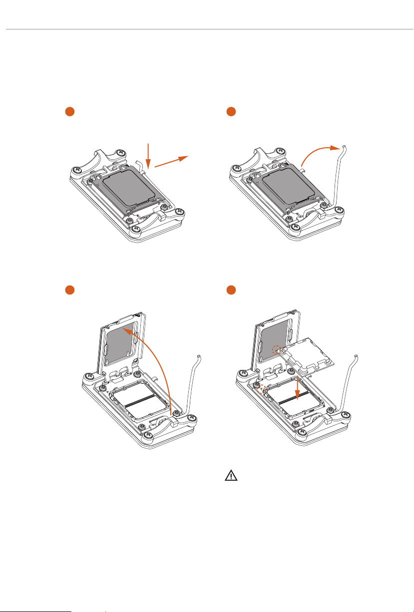
2.1 Installing the CPU
1. Before you insert the 1718-Pin CPU into the socket , please check if the PnP cap is on the
socket, if the CPU surface is unclean , or if there are any bent pins in the socket. Do not
force to in sert the CPU into the socket if above situation is found. Otherwise, the CPU
will be seriously damaged.
2. Unplug all power cables be fore installing the CPU.
Tutorial Video
X670E Pro RS
Turn your CPU to the correct orientation before opening
the CPU socket cover.
15
1
A
B
2
16
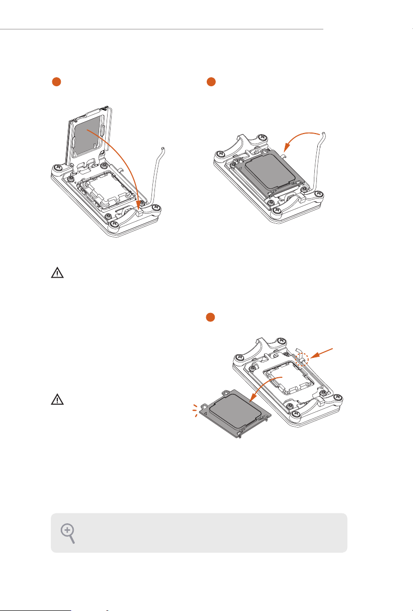
3
4
Carefully place the CPU in as at as
possible. Do not drop it.
X670E Pro RS
5
Make sure the CPU is aligned with the
socket before locking it into place.
6
7
Make sure the black cover plate
is always in place until it pops o
when closing the socket lever.
Please save the cover if the processor is removed. e cover must be placed if you wish to
return the motherboard for aer service.
17

2.2 Installing the CPU Fan and Heatsink
1
Aer you install the CPU into this motherboard, it is necessary to install a larger
heatsink and cooling fan to dissipate heat. You also need to spray thermal grease
between the CPU and the heatsink to improve heat dissipation. Make sure that the
CPU and the heatsink are securely fastened and in good contact with each other.
Please turn o the power or remove the powe r cord before changing a CPU or heatsink.
Installing the CPU Cooler (Type 1)
18
2

X670E Pro RS
3
4
CPU_FAN1
19
 Loading...