

ASRock X470 Taichi Service Manual

Version 1.0
Published March 2018
Copyright©2018 ASRock INC. All rights reserved.
Copyright Notice:
No part of this documentation may be reproduced, transcribed, transmitted, or
translated in any language, in any form or by any means, except duplication of
documentation by the purchaser for backup purpose, without written consent of
ASRock Inc.
Products and corporate names appearing in this documentation may or may not
be registered trademarks or copyrights of their respective companies, and are used
only for identication or explanation and to the owners’ benet, without intent to
infringe.
Disclaimer:
Specications and information contained in this documentation are furnished for
informational use only and subject to change without notice, and should not be
constructed as a commitment by ASRock. ASRock assumes no responsibility for
any errors or omissions that may appear in this documentation.
With respect to the contents of this documentation, ASRock does not provide
warranty of any kind, either expressed or implied, including but not limited to
the implied warranties or conditions of merchantability or tness for a particular
purpose.
In no event shall ASRock, its directors, ocers, employees, or agents be liable for
any indirect, special, incidental, or consequential damages (including damages for
loss of prots, loss of business, loss of data, interruption of business and the like),
even if ASRock has been advised of the possibility of such damages arising from any
defect or error in the documentation or product.
is device complies with Part 15 of the FCC Rules. Operation is subject to the following
two conditions:
(1) this device may not cause harmful interference, and
(2) this device must accept any interference received, including interference that
may cause undesired operation.
CALIFORNIA, USA ONLY
e Lithium battery adopted on this motherboard contains Perchlorate, a toxic substance
controlled in Perchlorate Best Management Practices (BMP) regulations passed by the
California Legislature. When you discard the Lithium battery in California, USA, please
follow the related regulations in advance.
“Perchlorate Material-special handling may apply, see ww w.dtsc.ca.gov/hazardouswaste/
perchlorate”
ASRock Website: http://www.asrock.com
AUSTRALIA ONLY
Our goods come with guarantees that cannot be excluded under the Australian Consumer
Law. You are entitled to a replacement or refund for a major failure and compensation for
any other reasonably foreseeable loss or damage caused by our goods. You are also entitled
to have the goods repaired or replaced if the goods fail to be of acceptable quality and the
failure does not amount to a major failure. If you require assistance please call ASRock Tel
: +886-2-28965588 ext.123 (Standard International call charges apply)
e terms HDMI™ and HDMI High-Denition Multimedia Interface, and the HDMI
logo are trademarks or registered trademarks of HDMI Licensing LLC in the United
States and other countries.
Manufactured under license under U.S. Patent Nos: 5,956,674; 5,974,380; 6,487,535;
7,003,467 & other U.S. and worldwide patents issued & pending. DTS, the Symbol, &
DTS and the Symbol together is a registered trademark & DTS Connect, DTS Interactive,
DTS Neo:PC are trademarks of DTS, Inc. Product includes soware.
© DTS, Inc., All Rights Reserved.
CE Warning
is device complies with directive 2014/53/EU issued by the Commision of the European
Community.
is equipment complies with EU radiation exposure limits set forth for an uncontrolled
environment.
is equipment should be installed and operated with minimum distance 20cm between
the radiator & your body.
Operations in the 5.15-5.35GHz band are restricted to indoor usage only.
Radio transmit power per transceiver ty pe
Function Frequency Maximum Output Power (EIRP)
2400-2483.5 MHz 18.5 + / -1.5 dbm
5150-5250 MHz 21.5 + / -1.5 dbm
WiFi
Bluetooth 2400-2483.5 MHz 8.5 + / -1.5 dbm
5250-5350 MHz
5470-5725 MHz
18.5 + / -1.5 dbm (no TPC)
21.5 + / -1.5 dbm (TPC)
25.5 + / -1.5 dbm (no TPC)
28.5 + / -1.5 dbm (TPC)

Contents
Chapter 1 Introduction 1
1.1 Package Contents 1
1.2 Specications 2
1.3 Motherboard Layout 8
1.4 I/O Panel 10
Chapter 2 Installation 14
2.1 Installing the CPU 15
2.2 Installing the CPU Fan and Heatsink 17
2.3 Installing Memory Modules (DIMM) 26
2.4 Expansion Slots (PCI Express Slots) 29
2.5 Jumpers Setup 30
2.6 Onboard Headers and Connectors 31
2.7 Smart Switch 37
2.8 Dr. Debug 38
2.9 SLITM and Quad SLITM Operation Guide 40
2.9.1 Installing Two SLITM-Ready Graphics Cards 40
2.9.2 Driver Installation and Setup 42
2.10 CrossFireXTM and Quad CrossFireXTM Operation Guide 43
2.10.1 Installing Two CrossFireXTM-Ready Graphics Cards 43
2.10.2 Driver Installation and Setup 45
2.11 M.2_SSD (NGFF) Module Installation Guide (M2_1) 46

2.12 M.2_SSD (NGFF) Module Installation Guide (M2_2) 49
Chapter 3 Software and Utilities Operation 52
3.1 Installing Drivers 52
3.2 A-Tuning 53
3.2.1 Installing A-Tuning 53
3.2.2 Using A-Tuning 53
3.3 ASRock Live Update & APP Shop 56
3.3.1 UI Overview 56
3.3.2 Apps 57
3.3.3 BIOS & Drivers 60
3.3.4 Setting 61
3.4 ASRock Polychrome RGB 62
Chapter 4 UEFI SETUP UTILITY 65
4.1 Introduction 65
4.1.1 UEFI Menu Bar 65
4.1.2 Navigation Keys 66
4.2 Main Screen 67
4.3 OC Tweaker Screen 68
4.4 Advanced Screen 71
4.4.1 CPU Conguration 72
4.4.2 North Bridge Conguration 73
4.4.3 South Bridge Conguration 74
4.4.4 Storage Conguration 75
4.4.5 Super IO Conguration 76

4.4.6 ACPI Conguration 77
4.4.7 AMD CBS 78
4.4.8 AMD PBS 86
4.5 Tools 87
4.6 Hardware Health Event Monitoring Screen 89
4.7 Security Screen 92
4.8 Boot Screen 93
4.9 Exit Screen 95
Chapter 1 Introduction
ank you for purchasing ASRock X470 Taichi motherboard, a reliable
motherboard produced under ASRock’s consistently stringent quality control.
It delivers excellent performance with robust design conforming to ASRock’s
commitment to quality and endurance.
In this documentation, Chapter 1 and 2 contains the introduction of the
motherboard and step-by-step installation guides. Chapter 3 contains the operation
guide of the soware and utilities. Chapter 4 contains the conguration guide of
the BIOS setup.
Becau se the motherboard specications and the BIOS soware might be updated, the
content of this documentation will be subject to change without notice. In case any modications of this documentation occur, the updated version will be available on ASRock’s
website w ithout further notice. If you require technical support related to this motherboard, please visit our website for specic information about the model you are using. You
may nd the l atest VGA cards and CPU suppor t list on ASRock’s website a s well. ASRock
website http://www.asrock.com.
X470 Taichi
1.1 Package Contents
ASRock X470 Taichi Motherboard (ATX Form Factor)
•
ASRock X470 Taichi Quick Installation Guide
•
ASRock X470 Taichi Support CD
•
1 x I/O Panel Shield
•
4 x Serial ATA (SATA) Data Cables (Optional)
•
1 x ASRock SLI_HB_Bridge_2S Card (Optional)
•
2 x ASRock WiFi 2.4/5 GHz Antennas
•
2 x Screws for M.2 Socket (Optional)
•
English
1

English
1.2 Specications
Platform
CPU
Chipset
Memory
•
•
•
•
•
•
•
•
•
•
•
•
•
•
* For Ryzen Series CPUs (Raven Ridge), ECC is only supported
with PRO CPUs.
* Please refer to Memory Support List on ASRock’s website for
more information. (http://www.asrock.com/)
* Please refer to page 26 for DDR4 UDIMM maximum
frequency support.
•
•
ATX Form Factor
2oz Copper PCB
Supports AMD AM4 Socket Ryzen Series CPUs (Summit
Ridge, Raven Ridge and Pinnacle Ridge)
IR Digital PWM
16 Power Phase design
Supports 300W EX OC
Supports ASRock Hyper BCLK Engine II
Supports 105W Water Cooling (Pinnacle Ridge); Supports
95W Water Cooling (Summit Ridge); Supports 65W Water
Cooling (Raven Ridge)
AMD Promontory X470
Dual Channel DDR4 Memory Technology
4 x DDR4 DIMM Slots
AMD Ryzen series CPUs (Pinnacle Ridge) support DDR4
3466+(OC)/3200(OC)/2933/2667/2400/2133 ECC & non-
ECC, un-buered memory*
AMD Ryzen series CPUs (Summit Ridge) support DDR4
3466+(OC)/3200(OC)/2933(OC)/2667/2400/2133 ECC &
non-ECC, un-buered memory*
AMD Ryzen series CPUs (Raven Ridge) support DDR4
3466+(OC)/3200(OC)/2933(OC)/2667/2400/2133 non-ECC,
un-buered memory*
Max. capacity of system memory: 64GB
15μ Gold Contact in DIMM Slots
2

Expansion
Slot
Graphics
2 x PCI Express 3.0 x16 Slots (single at x16 (PCIE1); dual at
•
x8 (PCIE1) / x8 (PCIE3))*
* Supports NVMe SSD as boot disks
1 x PCI Express 2.0 x16 Slot (PCIE5 @ x4 mode)
•
* If PCIE5 slot is occupied, M2 _2 will be disabled
2 x PCI Express 2.0 x1 Slots (Flexible PCIe)
•
Supports AMD Quad CrossFireXTM and CrossFireXTM
•
Supports NVIDIA® Quad SLITM and SLI
•
1 x Vertical M.2 Socket (Key E) with the bundled WiFi-
•
802.11ac module (on the rear I/O)
15μ Gold Contact in VGA PCIe Slot (PCIE1 and PCIE3)
•
Integrated AMD RadeonTM Vega Series Graphics in Ryzen
•
Series APU*
* Actual support may vary by CPU
DirectX 12, Pixel Shader 5.0
•
Max. shared memory 2GB
•
Supports HDMI with max. resolution up to 4K x 2K
•
(4096x2160) @ 30Hz
Supports Auto Lip Sync, Deep Color (12bpc), xvYCC and
•
HBR (High Bit Rate Audio) with HDMI Ports (Compliant
HDMI monitor is required)
Supports HDCP with HDMI Port
•
Supports 4K Ultra HD (UHD) playback with HDMI Port
•
TM
X470 Taichi
Audio
7.1 CH HD Audio with Content Protection (Realtek
•
ALC1220 Audio Codec)
Premium Blu-ray Audio support
•
Supports Surge Protection
•
Supports Purity SoundTM 4
•
- Nichicon Fine Gold Series Audio Caps
- 120dB SNR DAC with Dierential Amplier
- NE5532 Premium Headset Amplier for Front Panel
Audio Connector (Supports up to 600 Ohm headsets)
- Pure Power-In
- Direct Drive Technology
- PCB Isolate Shielding
English
3

LAN
Wireless
LAN
Rear Panel
I/O
- Impedance Sensing on Line Out port
- Individual PCB Layers for R/L Audio Channel
- RGB LED
- Gold Audio Jacks
- 15μ Gold Audio Connector
Supports DTS Connect
•
Gigabit LAN 10/100/10 00 Mb/s
•
GigaLAN Intel® I211AT
•
Supports Wake-On-LAN
•
Supports Lightning/ESD Protection
•
Supports Energy Ecient Ethernet 802.3az
•
Supports PXE
•
Intel® 802.11ac WiFi Module
•
Supports IEEE 802.11a/b/g/n/ac
•
Supports Dual-Band (2.4/5 GHz)
•
Supports high speed wireless connections up to 433Mbps
•
Supports Bluetooth 4.2 / 3.0 + High speed class II
•
2 x Antenna Ports
•
1 x PS/2 Mouse/Keyboard Port
•
1 x HDMI Port
•
1 x Optical SPDIF Out Port
•
1 x USB 3.1 Gen2 Type-A Port (10 Gb/s) (Supports ESD
•
Protection)
1 x USB 3.1 Gen2 Type-C Port (10 Gb/s) (Supports ESD
•
Protection)
6 x USB 3.1 Gen1 Ports (Supports ESD Protection)
•
1 x RJ-45 LAN Port with LED (ACT/LINK LED and SPEED
•
LED)
1 x Clear CMOS Button
•
HD Audio Jacks: Rear Speaker / Centra l / Bass / Line in /
•
Front Speaker / Microphone (Gold Audio Jacks)
English
4

Storage
Connector
X470 Taichi
6 x SATA3 6.0 Gb/s Connectors, support RAID (RAID 0,
•
RAID 1 and RAID 10), NCQ, AHCI and Hot Plug
2 x SATA3 6.0 Gb/s Connectors by ASMedia ASM1061, sup-
•
port NCQ, AHCI and Hot Plug
1 x Ultra M.2 Socket (M2_1), supports M Key type
•
2260/2280/22110 M.2 SATA3 6.0 Gb/s module and M.2 PCI
Express module up to Gen3 x4 (32 Gb/s)*
1 x M.2 Socket (M2_2), supports M Key type
•
2230/2242/2260/2280 M.2 SATA3 6.0 Gb/s module and M.2
PCI Express module up to Gen2 x4 (20 Gb/s)*
* If M2_2 is occupied, PCIE5 slot will be disabled
* Supports NVMe SSD as boot disks
* Supports ASRock U.2 Kit
1 x Power LED and Speaker Header
•
1 x AMD Fan LED Header
•
* e AMD Fan LED Header supports LED strips of maximum
load of 3A (36W) and length up to 2.5M.
1 x RGB LED Header
•
* Supports in total up to 12V/3A, 36W LED Strip
1 x Addressable LED Header
•
* Supports in total up to 5V/3A, 15W LED Strip
1 x CPU Fan Connector (4-pin)
•
* e CPU Fan Connector supports the CPU fan of ma ximum
1A (12W) fan power.
1 x CPU/Water Pump Fan Connector (4-pin) (Smart Fan
•
Speed Control)
* e CPU/Water Pump Fan supports the water cooler fan of
maximum 2A (24W) fan power.
3 x Chassis/Water Pump Fan Connectors (4-pin) (Smart Fan
•
Speed Control)
* e Chassis/Water Pump Fan supports the water cooler fan of
maximum 2A (24W) fan power.
* CPU_FAN2/WP, CHA_FAN1/WP, CHA_FAN2/WP and
CHA_FAN3/WP can auto detect if 3-pin or 4-pin fan is in use.
1 x 24 pin ATX Power Connector (Hi-Density Power
•
Connector)
English
5

BIOS
Feature
Hardware
Monitor
1 x 8 pin 12V Power Connector (Hi-Density Power
•
Connector)
1 x 4 pin 12V Power Connector (Hi-Density Power
•
Connector)
1 x Front Panel Audio Connector (15μ Gold Audio
•
Connec tor)
1 x AMD LED Fan USB Header
•
2 x USB 2.0 Headers (Support 4 USB 2.0 ports) (Supports
•
ESD Protection)
2 x USB 3.1 Gen1 Headers (Support 4 USB 3.1 Gen1 ports)
•
(Supports ESD Protection)
1 x Front Panel Type C USB 3.1 Gen2 Header (ASMedia
•
ASM314 2)
1 x Dr. Debug with LED
•
AMI UEFI Legal BIOS with GUI support
•
Supports “Plug and Play”
•
ACPI 5.1 compliance wake up events
•
Supports jumperfree
•
SMBIOS 2.3 support
•
CPU, VCORE_NB, DRAM, VPPM, PCH 1.05V, +1.8V,
•
VDDP, PROM 2.5V, Voltage Multi-adjustment
Temperature Sensing: CPU, CPU/Water Pump, Chassis,
•
Chassis/Water Pump Fans
Fan Tachometer: CPU, CPU/Water Pump, Chassis, Chassis/
•
Water Pump Fans
Quiet Fan (Auto adjust chassis fan speed by CPU tempera-
•
ture): CPU, CPU/Water Pump, Chassis, Chassis/Water
Pump Fans
Fan Multi-Speed Control: CPU, CPU/Water Pump, Chassis,
•
Chassis/Water Pump Fans
Voltage monitoring: +12V, +5V, +3.3V, CPU Vcore, VCORE_
•
NB, DRAM, PCH 1.05V, +1.8V, VDDP
English
6
OS
Microso® Windows® 10 64-bit
•
FCC, CE
Certications
* For detailed product information, please visit our website: http://www.asrock .com
Please realiz e that the re is a certain r isk involved with o verclocking, including adjusting
the setting in the BIOS, applying Untied Overclocking Technolog y, or using third-party
overclocking to ols. O verclocking may aect your system’s stability, or even c ause damage to
the components and devices of your system. It should be don e at your ow n risk and expense.
We are not responsibl e for possible damage caused by overclo cking.
•
ErP/EuP ready (ErP/EuP ready power supply is required)
•
X470 Taichi
English
7
DDR 4_A2 (6 4 bit, 28 8-pin m odule )
DDR 4_A1 (6 4 bit, 28 8-pin m odule )
DDR 4_B2 (6 4 bit, 28 8-pin m odule )
DDR 4_B1 (6 4 bit, 28 8-pin m odule )
ATXP WR 1
PCIE1
USB 3.1 Gen1
T: USB5
B: USB6
USB 3.1 Gen1
T: USB3
B: USB4
Top:
Central/Bass
Center :
REAR SPK
Top:
LINE IN
Center :
FRONT
Bottom :
Optica l
SPDIF
Bottom :
MIC IN
PCIE3
HDLED RESET
PLED PWRBTN
PANEL1
1
1
SPK_PLED1
1
HD_AUDIO1
PCIE5
SATA3_1_2
SATA3_3_4
SATA3_A1_ A2
8
10
13
11
14
12
15
16
SATA3_5_6
17
18
19
USB_1_2
1
21
USB_3_4
1
22
27
1
7
6
Dr.
Debug
20
USB 3.1 G en1
T: USB1
B: USB2
PS2
Keyb oard
/Mous e
CMOS
Battery
23
CPU_FAN1
9
USB 3.1 Gen2
T: USB31_TA_1
B: USB31_TC_1
M2_2
CHA_FAN1/WP
CPU_FAN2/WP
5
4
USB3_7 _8
1
USB3_9 _10
1
AMD_FAN_LED1
1
LAN
AUDIO
CODEC
BIOS
ROM
RoHS
PCIE4
ATX12V1
CHA_FAN3/WP
M2_WIFI_1
CLRC
BTN1
1
USB_5
Top:
RJ-45
(I211AT)
Super
I/O
AMD
Promontory
X470
SOCKETAM4
CHA_FAN2/WP
25
26
RGB_LED1
1
24
ADDR_LED1
1
3
F_USB31_TC_1
PCIE2
M2_1
X470 Taichi
HDMI1
2
ATX12V2
CLRMOS1
1
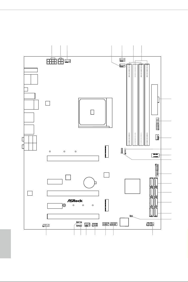
1.3 Motherboard Layout
English
8

No. Description
1 8 pin 12V Power Connector (ATX12V1)
2 4 pin 12V Power Connector (ATX12V2)
3 Chassis / Waterpump Fan Connector (CHA_FAN3/WP)
4 CPU / Waterpump Fan Connector (CPU_FAN2/WP)
5 CPU Fan Connector (CPU_FAN1)
6 2 x 288-pin DDR4 DIMM Slots (DDR4_A1, DDR4_B1)
7 2 x 288-pin DDR4 DIMM Slots (DDR4_A2, DDR4_B2)
8 ATX Power Connector (ATXPWR1)
9 USB 3.1 Gen1 Header (USB3_7_8)
10 CPU / Waterpump Fan Connector (CHA_FAN1/WP)
11 AMD LED Fan USB Header (USB_5)
12 Front Panel Type C USB 3.1 Gen2 Header (F_USB31_TC_1)
13 AMD FAN LED Header (AMD_FAN_LED1)
14 USB 3.1 Gen1 Header (USB3_9_10)
15 SATA3 Connectors (SATA3_1_2)
16 SATA 3 C on nectors (SATA 3_3 _4)
17 SATA3 Connectors (SATA3_5_6)
18 SATA3 Connectors (SATA3_A1_A2)
19 Clear CMOS Jumper (CLRCMOS1)
20 System Panel Header (PANEL1)
21 USB 2.0 Header (USB_1_2)
22 USB 2.0 Header (USB_3_4)
23 Power LED and Speaker Header (SPK_PLED1)
24 Chassis/Water Pump Fan Connector (CHA_FAN2/WP)
25 RGB LED Header (RGB_LED1)
26 Addressable LED Header (ADDR_LED1)
27 Front Panel Audio Header (HD_AUDIO1)
X470 Taichi
English
9
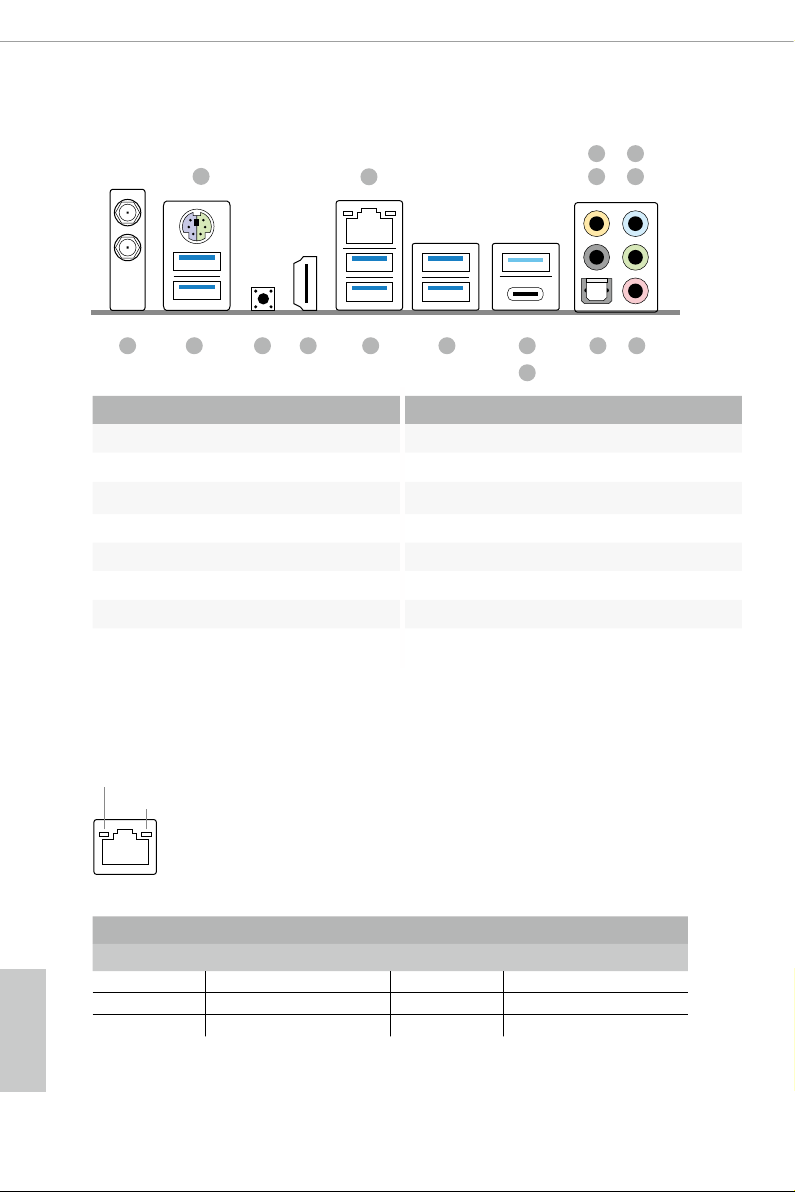
1.4 I/O Panel
1
5
2
436
15
No. Description No. Description
1 PS/2 Mouse/Keyboard Port 9 USB 3.1 Gen2 Type-A Port (USB31_TA_1)
2 LAN RJ-45 Port (Intel® I211AT)* 10 USB 3.1 Gen2 Type-C Port (USB31_TC_1)
3 Central / Bass (Orange) 11 USB 3.1 Gen1 Ports (USB3_5_6)
4 Rear Speaker (Black) 12 USB 3.1 Gen1 Ports (USB3_3_4)
5 Line In (Light Blue) 13 HDMI Port
6 Front Speaker (Lime)** 14 Clear CMOS Button
7 Microphone (Pink) 15 USB 3.1 Gen1 Ports (USB3_1_2)
8 Optical SPDIF Out Port 16 Antenna Ports
* ere are two LEDs on each LAN port. Please refer to the table below for the LAN port LED indications.
ACT/LINK LED
SPEED LED
LAN Por t
1416 1213
11
10
789
English
10
Activity / Link LED Speed LED
Status Description Status Description
O No Link O 10Mbps connection
Blinking Data Activity Orange 100Mbps connection
On Link Green 1Gbps connection

X470 Taichi
** If you use a 2- channel speaker, plea se connect the speake r’s plug into “Front Spea ker Jack”. See the table below
for connection d etails in accordance w ith the type of speaker you use.
Audio Output
Channels
2 V -- -- --
4 V V -- --
6 V V V --
8 V V V V
Front Speaker
(No. 6)
Rear Speaker
(No.4)
Central / Bass
(No. 3)
Line In
(No. 5)
11
English

1.5 WiFi-802.11ac Module and ASRock WiFi 2.4/5 GHz Antenna
WiFi-802.11ac + BT Module
is motherboard comes with an exclusive WiFi 802.11 a/b/g/n/ac + BT v4.2
module (pre-installed on the rear I/O panel) that oers support for WiFi 802.11 a/b/
g/n/ac connectivity standards and Bluetooth v4.2. WiFi + BT module is an easy-to-
use wireless local area network (WLAN) adapter to support WiFi + BT. Bluetooth
v4.2 standard features Smart Ready technology that adds a whole new class of
functionality into the mobile devices. BT 4.2 also includes Low Energy Technolog y
and ensures extraordinary low power consumption for PCs.
* e transmission speed may vary according to the environment.
English
12
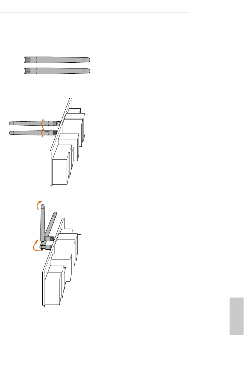
WiFi Antennas Installation Guide
X470 Taichi
Step 1
Prepare the WiFi 2.4/5 GHz Antennas that come
with the package.
Step 2
Connect the two WiFi 2.4/5 GHz Antennas to
the antenna connectors. Turn the antenna clock-
wise until it is securely connected.
Step 3
Set the WiFi 2.4/5 GHz Antenna as shown in the
illustration.
*You may need to adjust the direction of
the antenna for a stronger signal.
English
13

Chapter 2 Installation
is is an ATX form factor motherboard. Before you install the motherboard, study
the conguration of your chassis to ensure that the motherboard ts into it.
Pre-installation Precautions
Take note of the following precautions before you install motherboard components
or change any motherboard settings.
Make sure to unplug the power cord before installing or removing the motherboard.
•
Failure to do so may cause physical injuries to you and damages to motherboard
components.
In order to avoid damage from static electricity to the motherboard’s components,
•
NEVER place your motherboard directly on a carpet. Also remember to use a grounded
wrist strap or touch a safety grounded object before you handle the components.
Hold components by the edges and do not touch the ICs.
•
Whenever you uninstall any components, place them on a grounded anti-static pad or
•
in the bag that comes with the components.
When placing screws to secure the motherboard to the chassis, please do not over-
•
tighten the screws! Doing so may damage the motherboard.
English
14
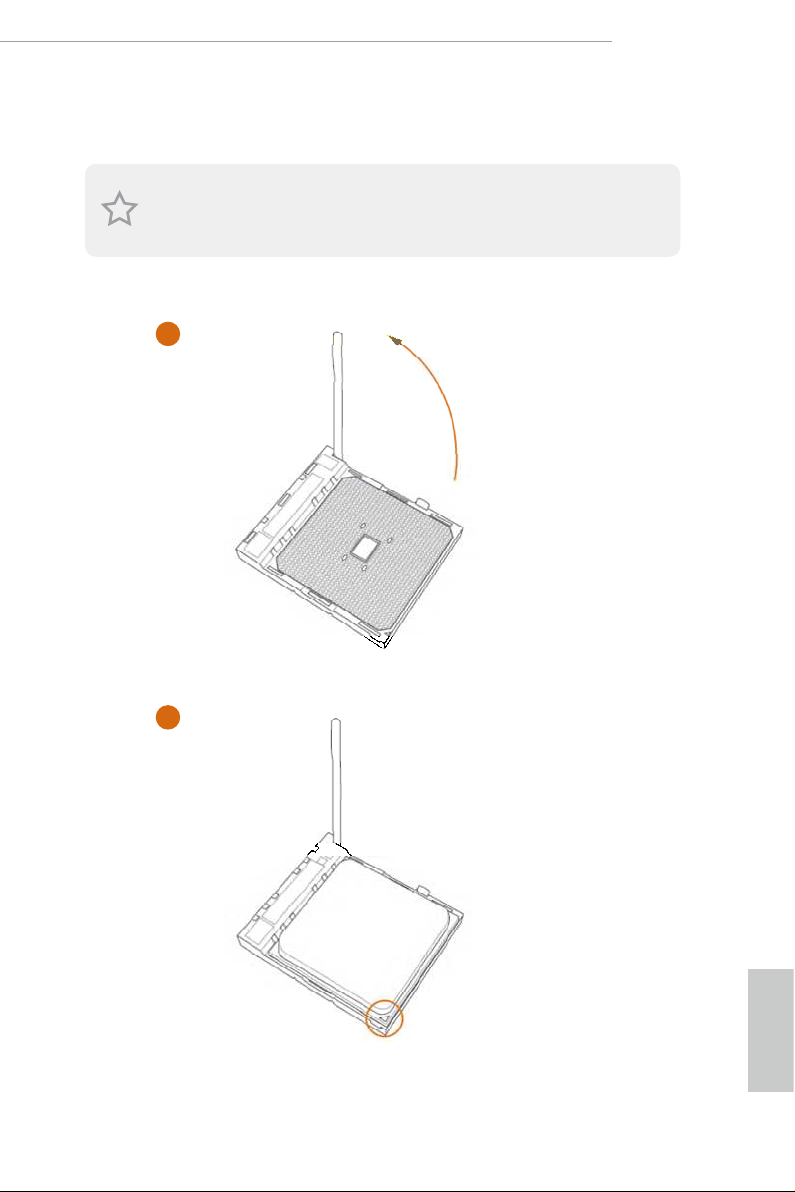
2.1 Installing the CPU
Unplug all power cables be fore installing the CPU.
1
X470 Taichi
2
English
15
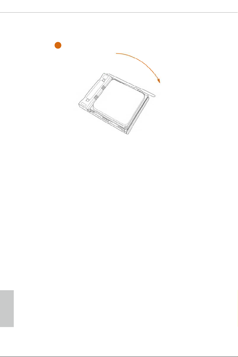
3
English
16
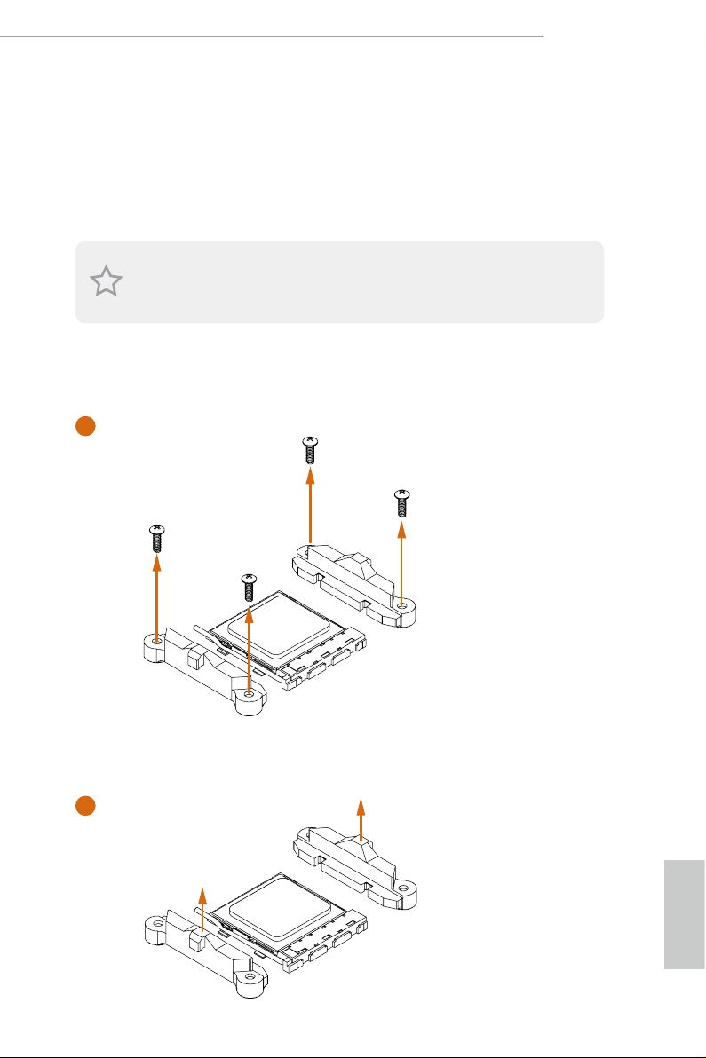
2.2 Installing the CPU Fan and Heatsink
Aer you install the CPU into this motherboard, it is necessary to install a larger
heatsink and cooling fan to dissipate heat. You also need to spray thermal grease
between the CPU and the heatsink to improve heat dissipation. Ma ke sure that the
CPU and the heatsink are securely fastened and in good contact with each other.
Please turn o the power or remove th e power cord before changing a CPU or heatsink.
Installing the CPU Box Cooler SR1
1
X470 Taichi
2
English
17
3
English
18
4
1
N
FA
_
U
P
C
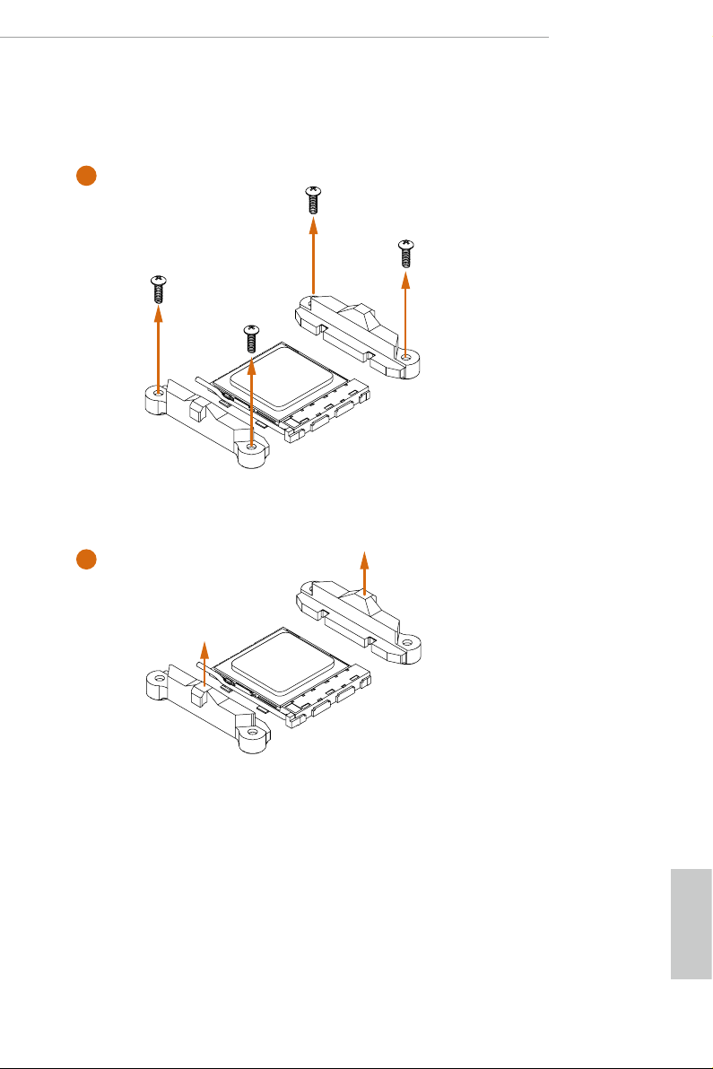
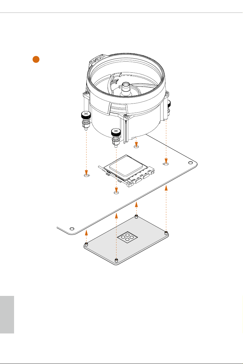
Installing the AM4 Box Cooler SR2
1
X470 Taichi
2
English
19
3
English
20
X470 Taichi
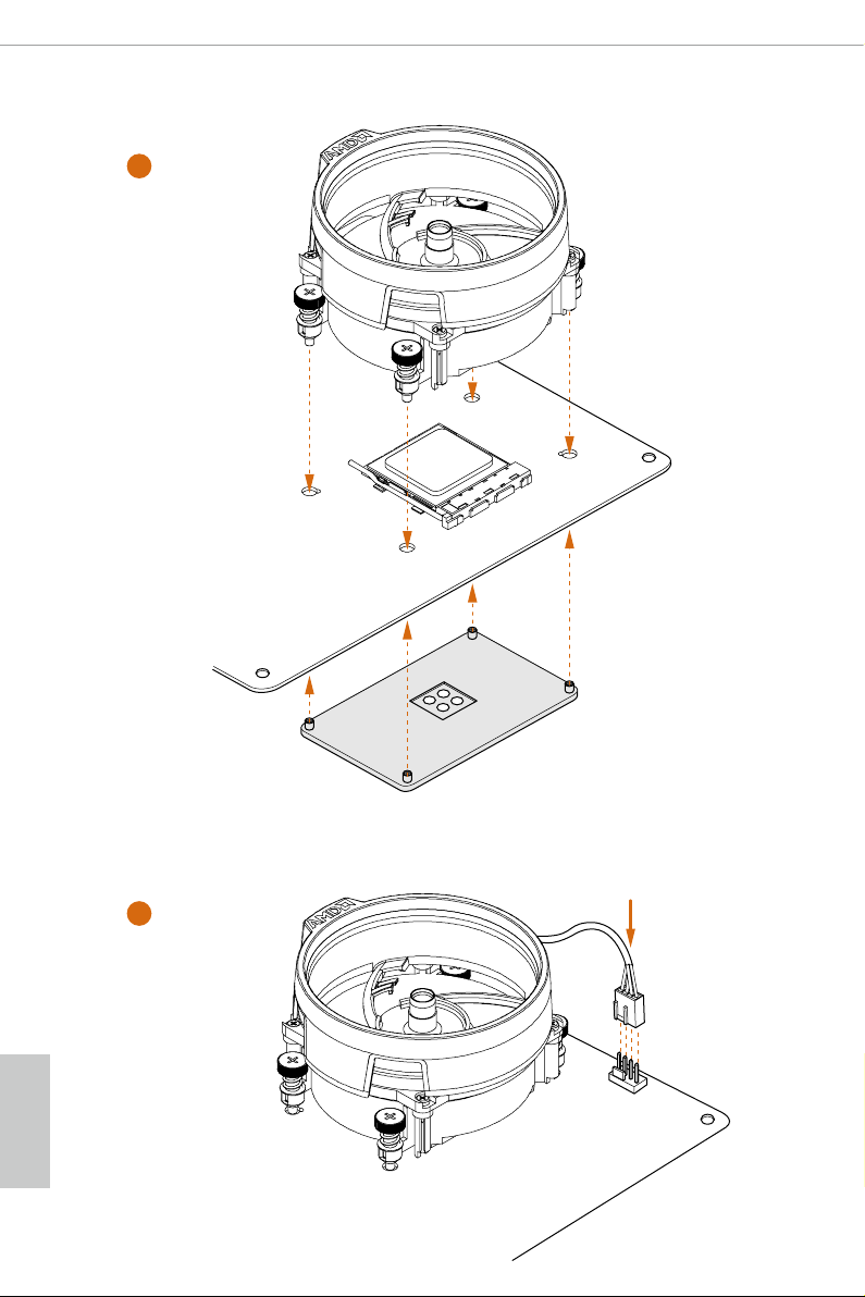
4
1
N
FA
_
U
P
C
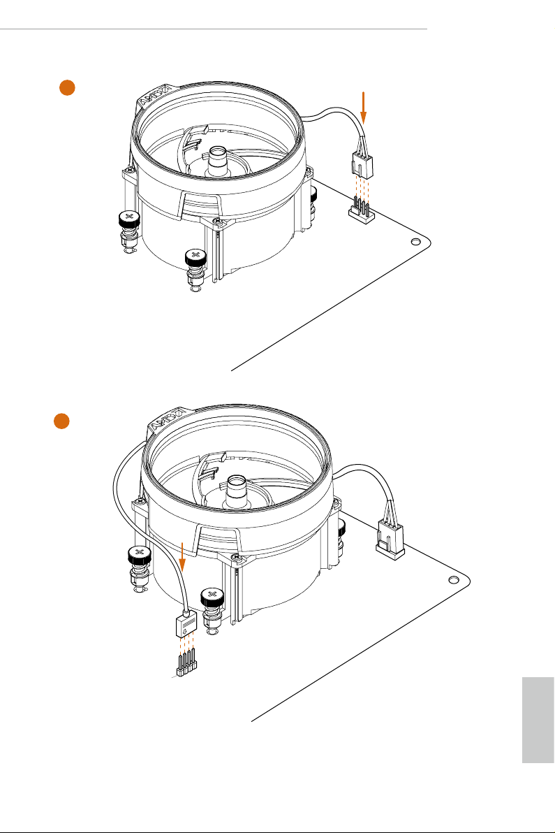
5
4-pin FAN cable
RGB LED Cable
1
N
FA
CPU_
1
D
E
L
_
N
FA
_
D
AM
+12V
*e diagram shown here are for reference only. Please refer to page 35 for the orientation of
AMD Fan LED Header (AMD_FAN_LED1).
English
21
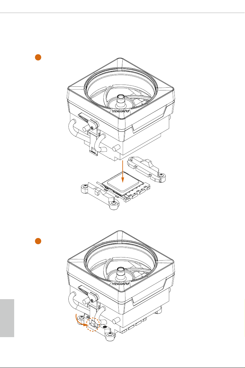
Installing the AM4 Box Cooler SR3
1
English
22
2
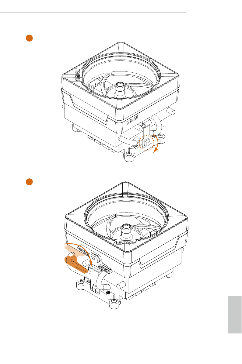
X470 Taichi
4
3
English
23
 Loading...