


Version 1.0
Published December 2021
Copyright©2021 ASRock INC. All rights reserved.
Copyright Notice:
No part of this documentation may be reproduced, transcribed, transmitted, or
translated in any language, in any form or by any means, except duplication of
documentation by the purchaser for backup purpose, without written consent of
ASRock Inc.
Products and corporate names appearing in this documentation may or may not
be registered trademarks or copyrights of their respective companies, and are used
only for identication or explanation and to the owners’ benet, without intent to
infringe.
Disclaimer:
Specications and information contained in this documentation are furnished for
informational use only and subject to change without notice, and should not be
constructed as a commitment by ASRock. ASRock assumes no responsibility for
any errors or omissions that may appear in this documentation.
With respect to the contents of this documentation, ASRock does not provide
warranty of any kind, either expressed or implied, including but not limited to
the implied warranties or conditions of merchantability or tness for a particular
purpose.
In no event shall ASRock, its directors, ocers, employees, or agents be liable for
any indirect, special, incidental, or consequential damages (including damages for
loss of prots, loss of business, loss of data, interruption of business and the like),
even if ASRock has been advised of the possibility of such damages arising from any
defect or error in the documentation or product.
is device complies with Part 15 of the FCC Rules. Operation is subject to the following
two conditions:
(1) this device may not cause harmful interference, and
(2) this device must accept any interference received, including interference that
may cause undesired operation.
CALIFORNIA, USA ONLY
e Lithium battery adopted on this motherboard contains Perchlorate, a toxic substance
controlled in Perchlorate Best Management Practices (BMP) regulations passed by the
California Legislature. When you discard the Lithium battery in California, USA, please
follow the related regulations in advance.
“Perchlorate Material-special handling may apply, see www.dtsc.ca.gov/hazardouswaste/
perchlorate”
ASRock Website: http://www.asrock.com

AUSTRALIA ONLY
Our goods come with guarantees that cannot be excluded under the Australian Consumer
Law. You are entitled to a replacement or refund for a major failure and compensation for
any other reasonably foreseeable loss or damage caused by our goods. You are also entitled
to have the goods repaired or replaced if the goods fail to be of acceptable quality and the
failure does not amount to a major failure. If you require assistance please call ASRock Tel
: +886-2-28965588 ext.123 (Standard International call charges apply)
e terms HDMI® and HDMI High-Denition Multimedia Interface, and the HDMI
logo are trademarks or registered trademarks of HDMI Licensing LLC in the United
States and other countries.
INTEL END USER SOFTWARE LICENSE AGREEMENT
IMPORTANT - READ BEFORE COPYING, INSTALLING OR USING.
LICENSE. Licensee has a license under Intel’s copyrights to reproduce Intel’s Soware
only in its unmodied and binary form, (with the accompanying documentation, the
“Soware”) for Licensee’s personal use only, and not commercial use, in connection with
Intel-based products for which the Soware has been provided, subject to the following
conditions:
(a) Licensee may not disclose, distribute or transfer any part of the Soware, and You agree
to prevent unauthorized copying of the Soware.
(b) Licensee may not reverse engineer, decompile, or disassemble the Soware.
(c) Licensee may not sublicense the Soware.
(d) e Soware may contain the soware and other intellectual property of third party
suppliers, some of which may be identied in, and licensed in accordance with, an enclosed
license.txt le or other text or le.
(e) Intel has no obligation to provide any support, technical assistance or updates for the
Soware.
OWNERSHIP OF SOFTWARE AND COPYRIGHTS. Title to all copies of the Soware
remains with Intel or its licensors or suppliers. e Soware is copyrighted and protected
by the laws of the United States and other countries, and international treaty provisions.
Licensee may not remove any copyright notices from the Soware. Except as otherwise
expressly provided above, Intel grants no express or implied right under Intel patents,
copyrights, trademarks, or other intellectual property rights. Transfer of the license terminates Licensee’s right to use the Soware.
DISCLAIMER OF WARRANTY. e Soware is provided “AS IS” without warranty of
any kind, EITHER EXPRESS OR IMPLIED, INCLUDING WITHOUT LIMITATION,
WARRANTIES OF MERCHANTABILITY OR FITNESS FOR ANY PARTICULAR PURPOSE.
LIMITATION OF LIABILITY. NEITHER INTEL NOR ITS LICENSORS OR SUPPLIERS
WILL BE LIABLE FOR ANY LOSS OF PROFITS, LOSS OF USE, INTERRUPTION OF
BUSINESS, OR INDIRECT, SPECIAL, INCIDENTAL, OR CONSEQUENTIAL DAMAG

ES OF ANY KIND WHETHER UNDER THIS AGREEMENT OR OTHERWISE, EVEN
IF INTEL HAS BEEN ADVISED OF THE POSSIBILITY OF SUCH DAMAGES.
LICENSE TO USE COMMENTS AND SUGGESTIONS. is Agreement does NOT
obligate Licensee to provide Intel with comments or suggestions regarding the Soware.
However, if Licensee provides Intel with comments or suggestions for the modication,
correction, improvement or enhancement of (a) the Soware or (b) Intel products or
processes that work with the Soware, Licensee grants to Intel a non-exclusive, worldwide,
perpetual, irrevocable, transferable, royalty-free license, with the right to sublicense, under
Licensee’s intellectual property rights, to incorporate or otherwise utilize those comments
and suggestions.
TERMINATION OF THIS LICENSE. Intel or the sublicensor may terminate this license
at any time if Licensee is in breach of any of its terms or conditions. Upon termination,
Licensee will immediately destroy or return to Intel all copies of the Soware.
THIRD PARTY BENEFICIARY. Intel is an intended beneciary of the End User License
Agreement and has the right to enforce all of its terms.
U.S. GOVERNMENT RESTRICTED RIGHTS. e Soware is a commercial item (as
dened in 48 C.F.R. 2.101) consisting of commercial computer soware and commercial
computer soware documentation (as those terms are used in 48 C.F.R. 12.212), consistent
with 48 C.F.R. 12.212 and 48 C.F.R 227.7202-1 through 227.7202-4. You will not provide
the Soware to the U.S. Government. Contractor or Manufacturer is Intel Corporation,
2200 Mission College Blvd., Santa Clara, CA 95054.
EXPORT LAWS. Licensee agrees that neither Licensee nor Licensee’s subsidiaries will
export/re-export the Soware, directly or indirectly, to any country for which the U.S.
Department of Commerce or any other agency or department of the U.S. Government
or the foreign government from where it is shipping requires an export license, or other
governmental approval, without rst obtaining any such required license or approval. In
the event the Soware is exported from the U.S.A. or re-exported from a foreign destination by Licensee, Licensee will ensure that the distribution and export/re-export or import
of the Soware complies with all laws, regulations, orders, or other restrictions of the U.S.
Export Administration Regulations and the appropriate foreign government.
APPLICABLE LAWS. is Agreement and any dispute arising out of or relating to it will
be governed by the laws of the U.S.A. and Delaware, without regard to conict of laws
principles. e Parties to this Agreement exclude the application of the United Nations
Convention on Contracts for the International Sale of Goods (1980). e state and federal
courts sitting in Delaware, U.S.A. will have exclusive jurisdiction over any dispute arising
out of or relating to this Agreement. e Parties consent to personal jurisdiction and venue
in those courts. A Party that obtains a judgment against the other Party in the courts identied in this section may enforce that judgment in any court that has jurisdiction over the
Parties.
Licensee’s specic rights may vary from country to country.

Motherboard Layout
DDR 4_A1 (6 4 bit, 28 8-pin m odule )
DDR 4_A2 (6 4 bit, 28 8-pin m odule )
Sup er
I/O
LAN
AUDIO
CODEC
PCIE2
PCIE1
USB_3_ 4
USB_5_ 6
HD_AUDIO1
1
CPU_FAN1
CHA_FAN2
1
COM1
3
4
2
9
5
USB 2.0
T: USB1
B: USB2
CMOS
Battery
1
USB3_5 _6
1
1
1
HDLED RESET
PLED PWRBTN
PANEL1
1
RoHS
17
15
13
12
14
18
SPK_CI1
1
Top:
LINE I N
Cent er:
FRON T
Bott om:
MIC IN
RJ- 45 LAN
ATX12V
7
8
6
CLRCMOS1
1
SOCKETAM4
CHA_FAN1
10
11
16
M2_1
X 3 7 0 M
HDM I1
Ultra M.2
PCIe Gen3x4
ATXP W R1
USB 3.2 Gen1
T: USB3_1
B: USB3_2
USB 3.2 Gen1
T: USB3_3
B: USB3_4
PS2
Keybo ard
/Mous e
AMD
Promontory
X370
SATA3_1
SATA3_2
SATA3_3
SATA3_4
X370M
FS B 8 0 0
English
BIOS
ROM
1

No. Description
1 ATX 12V Power Connector (ATX12V1)
2 CPU Fan Connector (CPU_FAN1)
3 2 x 288-pin DDR4 DIMM Slots (DDR4_A1, DDR4_A2)
4 ATX Power Connector (ATXPWR1)
5 USB 3.2 Gen1 Header (USB3_5_6)
6 USB 2.0 Header (USB_3_4)
7 USB 2.0 Header (USB_5_6)
8 SATA3 Connector (SATA3_3)
9 SATA3 Connector (SATA3_4)
10 SATA3 Connector (SATA3_2)
11 SATA3 Connector (SATA3_1)
12 System Panel Header (PANEL1)
13 Chassis Intrusion and Speaker Header (SPK_CI1)
14 COM Port Header (COM1)
15 Chassis Fan Connector (CHA_FAN2)
16 Clear CMOS Header (CLRCMOS1)
17 Front Panel Audio Header (HD_AUDIO1)
18 Chassis Fan Connector (CHA_FAN1)
English
2
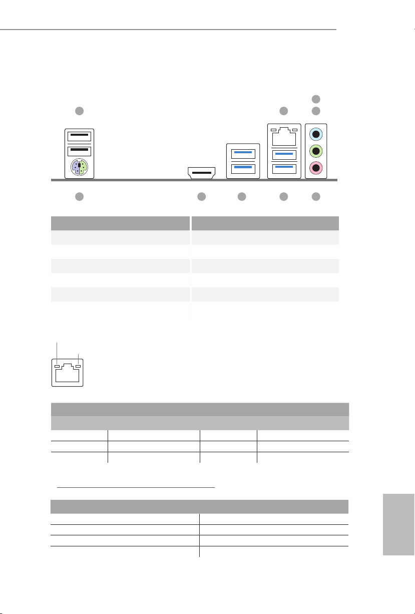
I/O Panel
1
X370M
3
2 4
9
5678
No. Description No. Description
1 USB 2.0 Ports (USB12) 6 USB 3.2 Gen1 Ports (USB3_34)
2 LAN RJ-45 Port* 7 USB 3.2 Gen1 Ports (USB3_12)
3 Line In (Light Blue)** 8 HDMI Port
4 Front Speaker (Lime)** 9 PS/2 Mouse/Keyboard Port
5 Microphone (Pink)** 10 Antenna Ports
* ere are two LEDs on each LAN port. Please refer to the table below for the LAN port LED indications.
ACT/LINK LED
SPEED LED
LAN Por t
Activity / Link LED Speed LED
Status Description Status Description
O No Link O 10Mbps connection
Blinking Data Activity Orange 100Mbps connection
On Link Green 1Gbps connection
** Function of the Audio Ports in 7.1-channel Conguration:
Port Function
Light Blue (Rear panel) Rear Speaker Out
Lime (Rear panel) Front Speaker Out
Pink (Rear panel) Central /Subwoofer Speaker Out
Lime (Front panel) Side Speaker Out
English
3
Chapter 1 Introduction
ank you for purchasing ASRock X370M motherboard, a reliable motherboard
produced under ASRock’s consistently stringent quality control. It delivers excellent
performance with robust design conforming to ASRock’s commitment to quality
and endurance.
Becau se the motherboard specication s and the BIOS soware might be updated, the
content of this manual will be subjec t to change without notice. In case any modications of this manual occur, the updated version will be available on ASRock’s website
without further notice. If you require technical support related to this motherboard,
please visit our website for specic information about the model you are using. You
may nd the l atest VGA cards and CPU support list on ASRock’s website as well.
ASRock website http://www.asrock.com.
1.1 Package Contents
ASRock X370M Motherboard (Micro ATX Form Factor)
•
ASRock X370M Quick Installation Guide
•
ASRock X370M Support CD
•
1 x I/O Panel Shield
•
2 x Serial ATA (SATA) Data Cables (Optional)
•
1 x Screw for M.2 Socket (Optional)
•
English
4

1.2 Specications
Platform
CPU
Chipset
Memory
•
•
•
•
•
•
•
•
•
•
•
•
•
•
•
* For Ryzen Series APUs (Picasso and Renoir), ECC is only
supported with PRO CPUs.
* Please refer to Memory Support List on ASRock’s website for
more information. (http://www.asrock.com/)
* Please refer to page 20 for DDR4 UDIMM maximum
frequency support.
X370M
Micro ATX Form Factor
Solid Capacitor design
Supports AMD AM4 Socket RyzenTM 2000, 3000, 4000
G-Series and 5000 Desktop Processors
6 Power Phase design
Supports CPU up to 105W
AMD Promontory X370
Dual Channel DDR4 Memory Technology
2 x DDR4 DIMM Slots
AMD Ryzen series CPUs (Vermeer) support DDR4
3200/2933/2667/2400/2133 ECC & non-ECC, un-buered
memory*
AMD Ryzen series CPUs (Matisse) support DDR4
3200/2933/2667/2400/2133 ECC & non-ECC, un-buered
memory*
AMD Ryzen series APUs (Renoir) support DDR4
3200/2933/2667/2400/2133 ECC & non-ECC, un-buered
memory*
AMD Ryzen series CPUs (Pinnacle Ridge) support DDR4
3200+(OC)/2933(OC)/2667/2400/2133 ECC & non-ECC, unbuered memory*
AMD Ryzen series CPUs (Picasso) support DDR4
2933/2667/2400/2133 non-ECC, un-buered memory*
AMD Ryzen series CPUs (Summit Ridge) support DDR4
3200+(OC)/2933(OC)/2667/2400/2133 ECC & non-ECC, unbuered memory*
AMD Ryzen series CPUs (Raven Ridge) support DDR4
3200+(OC)/2933/2667/2400/2133 non-ECC, un-buered
memory*
English
5

Max. capacity of system memory: 32GB
•
15μ Gold Contact in DIMM Slots
•
Expansion
Slot
Graphics
AMD Ryzen series CPUs (Vermeer, Matisse, Summit Ridge,
Renoir and Pinnacle Ridge)
1 x PCI Express 3.0 x16 Slot (PCIE2: x16 mode)*
•
AMD Ryzen series CPUs (Picasso, Raven Ridge)
1 x PCI Express 3.0 x16 Slot (PCIE2: x8 mode)*
•
AMD Athlon 2xxGE series APU
1 x PCI Express 3.0 x16 Slot (PCIE2: x4 mode)*
•
* Supports NVMe SSD as boot disks
1 x PCI Express 2.0 x1 Slot
•
Integrated AMD RadeonTM Vega Series Graphics in Ryzen
•
Series APU*
* Actual support may vary by CPU
DirectX 12, Pixel Shader 5.0
•
Shared memory default 2GB. Max Shared memory supports
•
up to 16GB.
* e Max shared memory 16GB requires 32GB system memory
installed.
Supports HDMI 1.4 with max. resolution up to 4K x 2K
•
(4096x2160) @ 24Hz / (3840x2160) @ 30Hz
Supports Auto Lip Sync, Deep Color (12bpc), xvYCC and
•
HBR (High Bit Rate Audio) with HDMI 1.4 Port (Compliant
HDMI monitor is required)
Supports HDCP 1.4 with HDMI 1.4 Port
•
Supports Full HD 1080p Blu-ray (BD) playback with HDMI
•
1.4 Port
English
6
Audio
7.1 CH HD Audio (Realtek ALC887 Audio Codec)
•
Supports Surge Protection
•
ELNA Audio Caps
•

LAN
Rear Panel
I/O
Storage
PCIE x1 Gigabit LAN 10/100/1000 Mb/s
•
Realtek RTL8111H
•
Supports Wake-On-LAN
•
Supports Lightning/ESD Protection
•
Supports Energy Ecient Ethernet 802.3az
•
Supports PXE
•
1 x PS/2 Mouse/Keyboard Port
•
1 x HDMI Port
•
2 x USB 2.0 Ports (Supports ESD Protection)
•
4 x USB 3.2 Gen1 Ports (Supports ESD Protection)
•
1 x RJ-45 LAN Port with LED (ACT/LINK LED and SPEED
•
LED)
HD Audio Jacks: Line in / Front Speaker / Microphone
•
4 x SATA3 6.0 Gb/s Connectors, support RAID (RAID 0,
•
RAID 1 and RAID 10), NCQ, AHCI and Hot Plug
1 x Ultra M.2 Socket, supports M Key type 2242/2260/2280
•
M.2 SATA3 6.0 Gb/s module and M.2 PCI Express module up
to Gen3 x4 (32 Gb/s) (with Vermeer, Matisse, Picasso,
Summit Ridge, Raven Ridge, Renoir and Pinnacle Ridge) or
Gen3 x2 (16 Gb/s) (with Athlon 2xxGE series APU)*
* Supports NVMe SSD as boot disks
* Supports ASRock U.2 Kit
X370M
Connector
1 x COM Port Header
•
1 x Chassis Intrusion and Speaker Header
•
1 x CPU Fan Connector (4-pin)
•
* e CPU Fan Connector supports the CPU fan of maximum
1A (12W) fan power.
2 x Chassis Fan Connectors (1 x 4-pin, 1 x 3-pin)
•
* e Chassis Fan Connector supports the chassis fan of
maximum 1A (12W) fan power.
1 x 24 pin ATX Power Connector
•
1 x 4 pin 12V Power Connector
•
1 x Front Panel Audio Connector
•
2 x USB 2.0 Headers (Support 4 USB 2.0 ports) (Supports ESD
•
Protection)
1 x USB 3.2 Gen1 Header (Supports 2 USB 3.2 Gen1 ports)
•
(Supports ESD Protection)
English
7
AMI UEFI Legal BIOS with GUI support
BIOS
Feature
Hardware
Monitor
OS
•
Supports “Plug and Play”
•
ACPI 5.1 compliance wake up events
•
Supports jumperfree
•
SMBIOS 2.3 support
•
DRAM Voltage multi-adjustment
•
CPU/Chassis temperature sensing
•
CPU/Chassis Fan Tachometer
•
CPU/Chassis Quiet Fan
•
CPU/Chassis Fan multi-speed control
•
CASE OPEN detection
•
Voltage monitoring: +12V, +5V, +3.3V, Vcore
•
Microso® Windows® 10 64-bit / 11 64-bit
•
* Summit Ridge does not ocially support Windows® 11.
FCC, CE
Certications
* For detailed product infor mation, please visit our website: http://www.asrock .com
•
ErP/EuP ready (ErP/EuP ready power supply is required)
•
English
8
Please realize that there is a certain risk involved with overclocking, including adjusting the setting in the BIOS, applying Untied Overclocking Technology, or using thirdparty overclocking tool s. Overclocking may aect your system’s stability, or even cause
damage to the components and devices of your system. It should be done at your own
risk and expense. We are not re sponsible for possible damage caused by overclocking.

Chapter 2 Installation
is is a Micro ATX form factor motherboard. Before you install the motherboard,
study the conguration of your chassis to ensure that the motherboard ts into it.
Pre-installation Precautions
Take note of the following precautions before you install motherboard components
or change any motherboard settings.
Make sure to unplug the power cord before installing or removing the motherboard.
•
Failure to do so may cause physical injuries to you and damages to motherboard
components.
In order to avoid damage from static electricity to the motherboard’s components,
•
NEVER place your motherboard directly on a carpet. Also remember to use a grounded
wrist strap or touch a safety grounded object before you handle the components.
Hold components by the edges and do not touch the ICs.
•
Whenever you uninstall any components, place them on a grounded anti-static pad or
•
in the bag that comes with the components.
When placing screws to secure the motherboard to the chassis, please do not over-
•
tighten the screws! Doing so may damage the motherboard.
X370M
English
9

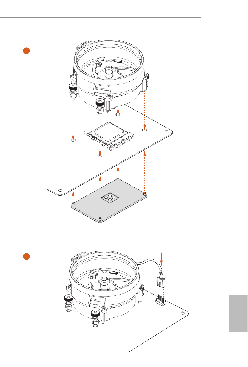
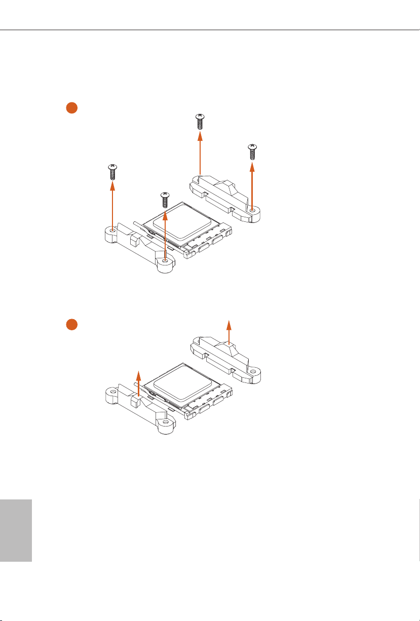
2.2 Installing the CPU Fan and Heatsink
Aer you install the CPU into this motherboard, it is necessary to install a larger
heatsink and cooling fan to dissipate heat. You also need to spray thermal grease
between the CPU and the heatsink to improve heat dissipation. Make sure that the
CPU and the heatsink are securely fastened and in good contact with each other.
Please turn o the power or remove the power cord before changing a CPU or heatsink .
Installing the CPU Box Cooler SR1
1
English
10
2
X370M
3
4
4-pin FAN cable
1
N
FA
_
U
P
C
English
11
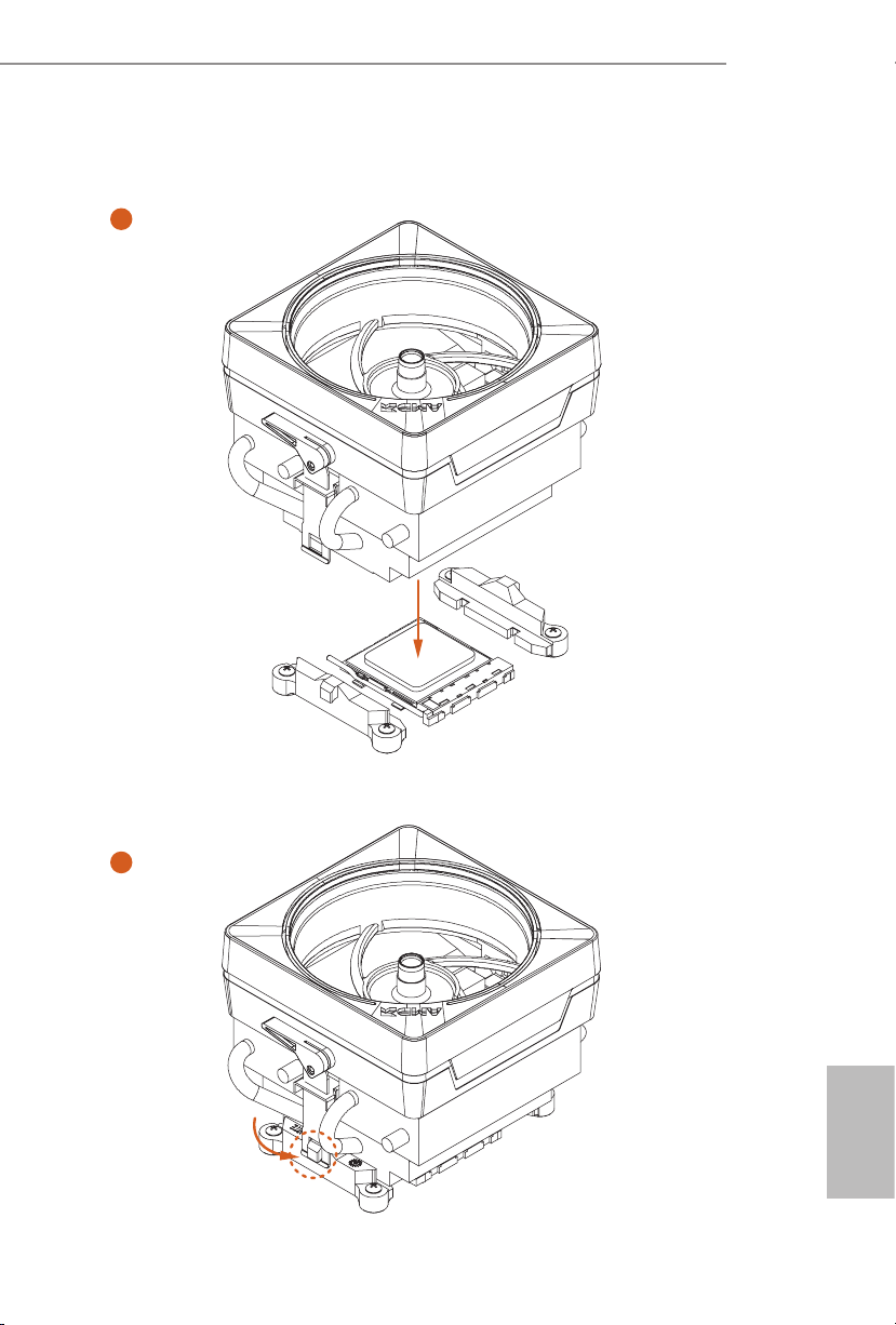
Installing the AM4 Box Cooler SR2
1
2
English
12

X370M
3
13
English

4
4-pin FAN cable
1
N
FA
_
U
P
C
English
14
Installing the AM4 Box Cooler SR3
1
X370M
2
English
15
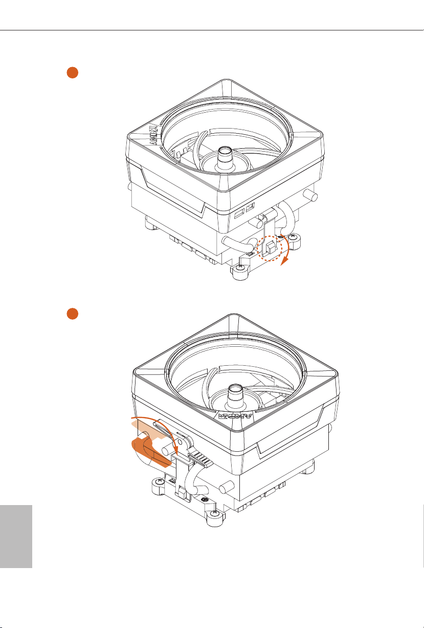
3
4
English
16

X370M
5
4-pin FAN cable
FAN1
CPU_
6
1
N
FA
_
U
P
C
USB 2.0 Header
B
S
U
Please note that this connector is the interface to the LED control board on the SR3, it requires the AMD
utility "SR3 Settings Soware" to control the LED.
*e diagram shown here are for reference only. Please refer to page 25 for the orientation of USB Header.
17
English

2.3 Installing Memory Modules (DIMM)
is motherboard provides two 288-pin DDR4 (Double Data Rate 4) DIMM slots,
and supports Dual Channel Memory Technology.
1. For dual channel conguration, you always need to install identical (the same
brand, speed, size and chip-ty pe) DDR4 DIMM pairs.
2. It is unable to activate Dual Channel Memory Technology w ith only one memor y
module installed.
3. It is not allowed to install a DDR, DDR2 or DDR 3 memory modul e into a DDR4
slot; otherwise, this motherboard and DIMM may be damaged.
AMD non-XMP Memory Frequency Support
Ryzen Series CPUs (Vermeer):
English
UDIMM Memory Slot
A1 B1
SR - 3200
- SR 3200
DR - 3200
- DR 3200
SR SR 3200
DR DR 3200
Ryzen Series CPUs (Matisse):
UDIMM Memory Slot
A1 B1
SR - 3200
- SR 3200
DR - 3200
- DR 3200
SR SR 3200
DR DR 3200
Frequency
(Mhz)
Frequency
(Mhz)
18

Ryzen Series CPUs (Renoir):
X370M
UDIMM Memory Slot
A1 B1
SR - 2933
- SR 2933
DR - 2933
- DR 2933
SR SR 2933
DR DR 2933
Ryzen Series CPUs (Pinnacle Ridge):
UDIMM Memory Slot
A1 B1
SR - 2933
- SR 2933
DR - 2933
- DR 2933
SR SR 2933
DR DR 2933
Frequency
(Mhz)
Frequency
(Mhz)
Ryzen Series CPUs (Picasso):
UDIMM Memory Slot
A1 B1
SR - 2933
- SR 2933
DR - 2667
- DR 2667
SR SR 2933
DR DR 2667
Frequency
(Mhz)
English
19

Ryzen Series CPUs (Summit Ridge):
UDIMM Memory Slot
A1 B1
SR - 2667
- SR 2667
DR - 2667
- DR 2667
SR SR 2667
DR DR 2667
Ryzen Series CPUs (Raven Ridge):
UDIMM Memory Slot
A1 B1
SR - 2933
- SR 2933
DR - 2667
- DR 2667
SR SR 2933
DR DR 2667
Frequency
(Mhz)
Frequency
(Mhz)
English
20
SR: Single rank DIMM, 1R x4 or 1Rx8 on DIMM module label
DR: Dual rank DIMM, 2R x4 or 2Rx8 on DIMM module label

X370M
e DIMM only ts in one correct orientation. It will cause permanent damage to
the motherboard and the DIMM if you force the DIMM into the slot at incorrect
orientation.
1
2
3
English
21

2.4 Expansion Slots (PCIe Slots)
ere are 2 PCIe slots on the motherboard.
Before installing an expansion card, please mak e sure that the power supply is
switched o or the power cord is unplug ged. Please read the documentation of the
expan sion card and make necessary hardware settings for the card before you star t
the installation.
PCIe slots:
PCIE1 (PCIe 2.0 x1 slot) is used for PCIe x1 lane width cards
PCIE2 (PCIe 3.0 x16 slot) is used for PCIe x16 lane width graphics cards.
PCIe Slot Congurations
CPU PCIE2
Ryzen series CPUs (Vermeer) x16
Ryzen series CPUs (Matisse) x16
English
22
Ryzen series APUs (Renoir)
Ryzen series CPUs (Pinnacle Ridge) x16
Ryzen series CPUs (Summit Ridge) x16
Ryzen series CPUs (Picasso) x8
Ryzen series CPUs (Raven Ridge) x8
Athlon 2x xGE series APU x4
For a better thermal environment , please connect a chassis fan to the motherboard’s
chassis fan connector (CHA_FAN1 or CHA_FAN2 ) when using multipl e graphics card s.
x16
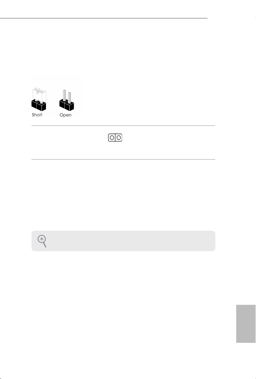
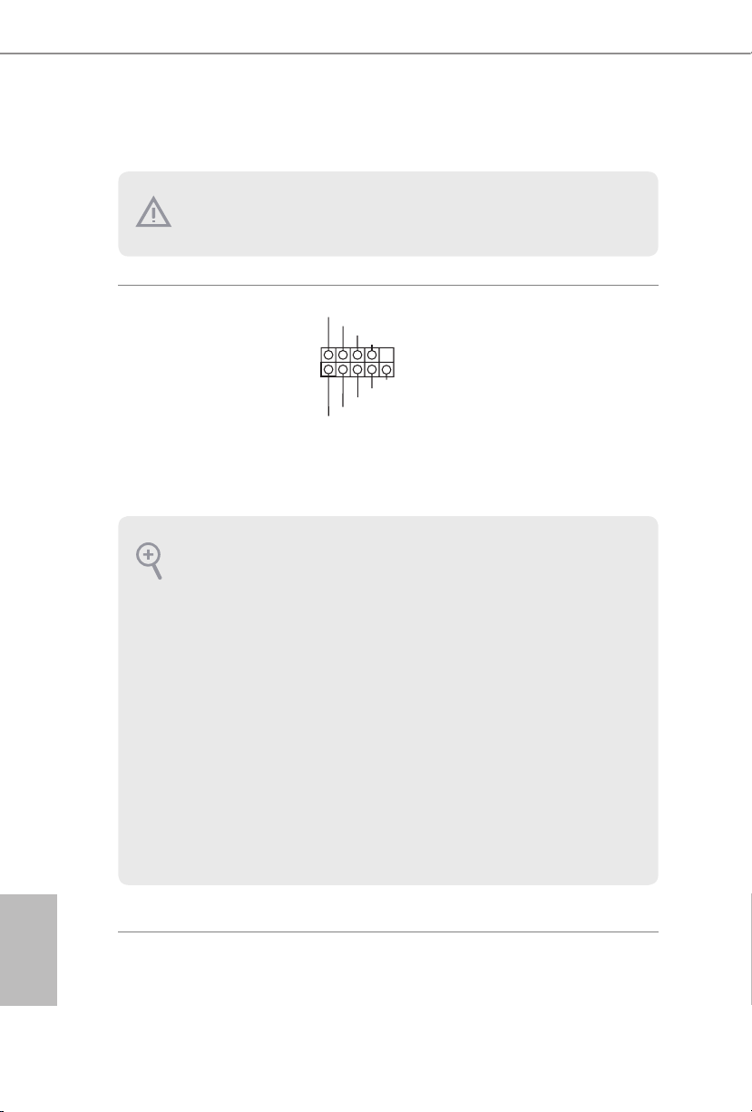
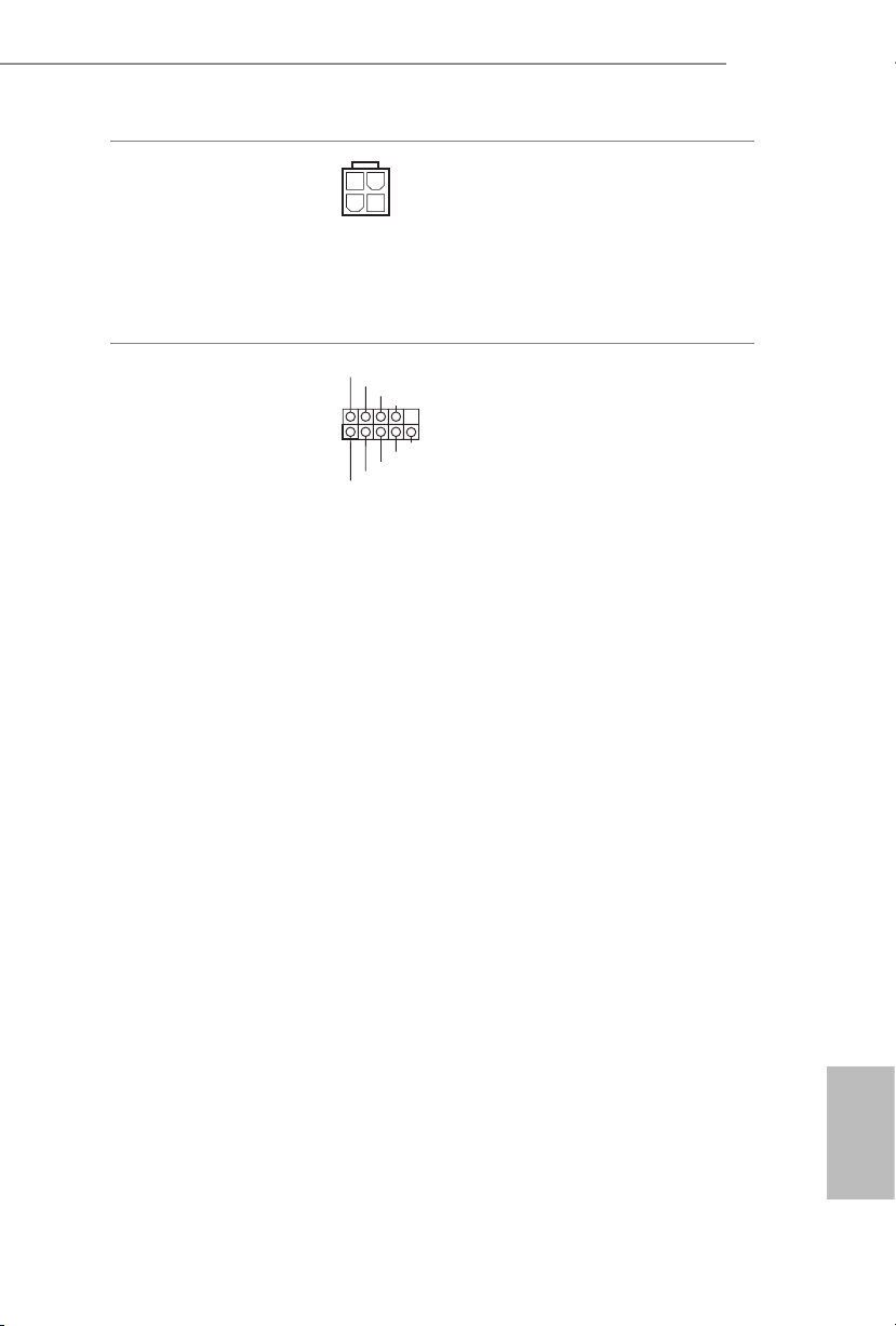
2.5 Jumpers Setup
e illustration shows how jumpers are setup. When the jumper cap is placed on
the pins, the jumper is “Short”. If no jumper cap is placed on the pins, the jumper is
“Open”.
X370M
Clear CMOS Header
(CLRCMOS1)
(see p.1, No. 16)
CLRCMOS1 allows you to clear the data in CMOS. e data in CMOS includes
system setup information such as system password, date, time, and system setup
parameters. To clear and reset the system parameters to default setup, please
turn o the computer and unplug the power cord, then use a jumper cap to short
the pins on CLRCMOS1 for 3 seconds. Please remember to remove the jumper
cap aer clearing the CMOS. If you need to clear the CMOS when you just nish
updating the BIOS, you must boot up the system rst, and then shut it down
before you do the clear-CMOS action.
If you clear the CMOS, the case open may be detected. Please adjust the BIOS option
“Clear Status” to clear the record of prev ious chassis intru sion status.
2-pin Jumper
Short: Clear CMOS
Open: Default
23
English
2.6 Onboard Headers and Connectors
1
Onboard headers and connectors are NOT jumpers. Do NOT place jumper caps over
these headers and connectors. Placing jumper caps over the headers and connectors
will cause permanent damage to the motherboard.
System Panel Header
(9-p in PA NEL1)
(see p.1, No. 12)
PWRBTN (Power But ton):
Connec t to the power button on the chassis f ront panel. You may congure the way to turn
o your system using the power button.
RESET (Reset Button):
Connec t to the reset button on the chassis f ront panel. Pre ss the reset button to restart the
computer if the computer freezes and fails to perform a normal restart.
PLED (Syste m Power LED):
Connec t to the power status indicator on the chassi s front panel. e LED is on when the
system is operating. e LED keeps blinking when the system is in S1/S3 sleep state. e
LED is o when the system is in S4 sleep state or powered o (S5).
HDLED (Ha rd Drive Activity LED):
Connec t to the hard drive activity LED on the chassis f ront panel. e LED is on when the
hard drive is reading or writing data .
e front panel design may dier by chassis . A front panel module mainly consists of powe r
button, reset button, power LED, hard drive a ctivity LED, speaker and etc. When connecting your chassis front panel module to this header, make sure the wire assig nments and the
pin assignments are matched correctly.
PLED+
PLED-
HDLED-
HDLED+
PWRBTN#
GND
RESET#
GND
GND
Connect the power
button, reset button and
system status indicator on
the chassis to this header
according to the pin
assignments below. Note
the positive and negative
pins before connecting
the cables.
English
24
X370M
DUMMY
GNDGND
+B
-B
+A
-A
USB_PWR
USB_PWR
1
1
+5V
DUMMY
SIGNAL
GND
DUMMY
SPEAKER
DUMMY
J_SENSE
OUT2_L
1
MIC_RET
PRESENCE#
GND
OUT2_R
MIC2_R
MIC2_L
OUT_RET
1
Chassis Intrusion and
Speaker Header
(7-pi n SPK_C I1)
(see p.1, No. 13)
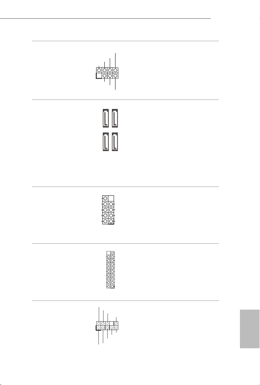
Serial ATA3 Connectors
Right Angle:
(SATA3_1:
see p.1, No. 11)
(SATA3_2:
see p.1, No. 10)
(SATA3_3:
see p.1, No. 8)
(SATA3_4:
see p.1, No. 9)
USB 2.0 Headers
(9-pin USB_3_4)
(see p.1, No. 6)
(9-pin USB_5_6)
(see p.1, No. 7)
SATA3_3
SATA3_1
SATA3_4
SATA3_2
Please connect the
chassis intrusion and the
chassis speaker to this
header.
ese four SATA3
connectors support SATA
data cables for internal
storage devices with up to
6.0 Gb/s data transfer rate.
ere are two headers
on this motherboard.
Each USB 2.0 header can
support two ports.
USB 3.2 Gen1 Header
(19-pin USB3_5_6)
(see p.1, No. 5)
Front Panel Audio Header
(9-pin HD_AUDIO1)
(see p.1, No. 17)
Vbus
IntA_PA_SSRX-
IntA_PA_SSRX+
GND
IntA_PA_SSTX-
IntA_PA_SSTX+
GND
IntA_PA_D-
IntA_PA_D+
VbusVbus
IntA_PB_SSRX-
IntA_PB_SSRX+
GND
IntA_PB_SSTX-
IntA_PB_SSTX+
GND
IntA_PB_D-
IntA_PB_D+
Dummy
ere is one header on
this motherboard. Each
USB 3.2 Gen1 header can
support two ports.
is header is for
connecting audio devices
to the front audio panel.
English
25
1. High Denition Audio supports Jack Sensing, but the panel wire on the chassis must
FAN_SPEED_CONTROL
FAN_SPEED_CONTROL
4
CHA_FAN_SPEED
suppor t HDA to function correctly. Please follow the instructions in our manual and
chassis manual to install your system.
2. If you use an AC’97 audio panel , please install it to the f ront panel audio header by
the steps below:
A. Connect Mic_ IN (MIC) to MIC2_L.
B. Conne ct Audio_R (RIN) to OUT2 _R and Audio_ L (LIN) to OUT2_ L.
C. Connect Ground (GND) to Ground (GND).
D. MIC_ RET and OUT_RET are for the HD audio panel only. You don’t need to connect them for the AC’97 audio panel.
E. To activate the front mic, go to the “FrontMic” Tab in the Realtek Control panel
and adjust “Recording Volume”.
English
Chassis Fan Connector
(4-pin CHA_FAN1)
(see p.1, No. 18)
(3-pi n C HA_FA N2)
(see p.1, No. 15)
CPU Fan Connector
(4-pin CPU_FAN1)
(see p.1, No. 2)
ATX Power Connector
(24-pin AT XPWR 1)
(see p.1, No. 4)
FAN_SPEED
FAN_VOLTAGE
GND
GND
FAN_VOLTAGE
CPU_FAN_SPEED
FAN_VOLTAGE
GND
1 2 3 4
12
1
Please connect fan cables
3
to the fan connectors and
2
1
match the black wire to
the ground pin.
is motherboard provides a 4-Pin CPU fan
(Quiet Fan) connector.
If you plan to connect a
3-Pin CPU fan, please
connect it to Pin 1-3.
24
is motherboard provides a 24-pin ATX power
connector. To use a 20-pin
ATX power supply, please
13
plug it along Pin 1 and Pin
13.
26
X370M
ATX 12V Power
Connector
(4-pin ATX12V1)
(see p.1, No. 1)
Serial Port Header
(9-pin COM1)
(see p.1, No. 14)
1
RRXD1
DDTR#1
TTXD1
DDCD#1
DDSR#1
CCTS#1
RRTS#1
GND
RRI#1
Please connect an ATX 12V
power supply to this connector.
*e power supply plug ts into
this connector in only one orientation.
is COM1 header
supports a serial port
module.
27
English

2.7 M.2_SSD (NGFF) Module Installation Guide
3
The M.2, also known as the Next Generation Form Factor (NGFF), is a small size and
versatile card edge connector that aims to replace mPCIe and mSATA. The Ultra M.2
Socket (M2_1) supports SATA3 6.0 Gb/s module and M.2 PCIe module up to Gen3
x4 (32 Gb/s) (with Vermeer, Matisse, Picasso, Summit Ridge, Raven Ridge, Renoir and
Pinnacle Ridge) or Gen3 x2 (16 Gb/s) (with Athlon 2xxGE series APU).
Installing the M.2_SSD (NGFF) Module
Step 1
Prepare a M.2_SSD (NGFF) module
and the screw.
English
2
1
ABC
No. 1 2 3
Nut Location A B C
PCB Length 4.2cm 6cm 8cm
Module Type Type 2 242 Type2 260 Ty pe 22 80
Step 2
Depending on the PCB type and
length of your M.2_SSD (NGFF)
module, nd the corresponding nut
location to be used.
28

X370M
Step 3
Move the stando based on the
module type and length.
ABC
ABC
ABC
e stando is placed at the nut
location D by default. Skip Step 3
and 4 and go straight to Step 5 if you
are going to use the default nut.
Otherwise, release the stando by
hand.
Step 4
Peel o the yellow protective lm on
the nut to be used. Hand tighten the
stando into the desired nut location
on the motherboard.
Step 5
Align and gently insert the M.2
(NGFF) SSD module into the M.2
slot. Please be aware that the M.2
(NGFF) SSD module only ts in one
orientation.
ABC
o
20
English
29

Step 6
Tighten the screw with a screwdriver
to secure the module into place.
NUT1NUT2C
Please do not overtighten the screw
as this might damage the module.
English
30

M.2_SSD (NGFF) Module Support List
Vendor Interface P/N
SanDisk PCIe SanDisk-SD6PP4M-128G( Gen2 x2)
Intel PCIe INTEL 6000P-SSDPEKKF256G7 (nvme)
Intel PCIe INTEL 6000P-SSDPEKKF512G7 (nvme)
Kingston PCIe Kingston SHPM2280P2 / 240G (Gen2 x4)
Samsung PCIe Samsung XP941-MZHPU512HCGL(Gen2x4)
ADATA SATA ADATA - AXNS381E-128GM-B
Crucial SATA Crucial-CT240M500SSD4-240GB
ezlink SATA ezlink P51B-80-120GB
Intel SATA INTEL 540S-SSDSCKKW240H6-240GB
Kingston SATA Kingston SM2280S3G2/120G - Win8.1
Kingston SATA Kingston-RBU-SNS8400S3 / 180GD
LITEON SATA LITEON LJ H-256V2G-256GB (2260)
PLEXTOR SATA PLEXTOR PX-128M6G-2260-128GB
PLEXTOR SATA PLEXTOR PX-128M7VG-128GB
SanDisk SATA SanDisk X400-SD8SN8U-128G
SanDisk SATA Sandisk Z400s-SD8SNAT-128G-1122
SanDisk SATA SanDisk-SD6SN1M-128G
Transcend SATA Transcend TS256GMTS800-256GB
V-Co lor SATA V-C olor 1 20G
V-Co lor SATA V-C olor 2 40G
WD SATA WD GREEN WDS240G1G0B-00RC30
X370M
For the latest updates of M.2_SSD (NFGG) module support list, please visit our website
for details: http://www.asrock.com
English
31
1 Einleitung
Vielen Dank, dass Sie sich für das ASRock X370M entschieden haben – ein zuverlässiges
Motherboard, das konsequent unter der strengen Qualitätskontrolle von ASRock hergestellt
wurde. Es liefert ausgezeichnete Leistung mit robustem Design, das ASRock Streben nach
Qualität und Beständigkeit erfüllt.
Da die technischen Daten des Motherboards sowie die BIOS-Soware aktualisiert werden
können, kann der Inhalt dieser Anleitung ohne Ankündigung geändert werden. Falls diese
Anleitung irgendwelchen Änderungen unterliegt, wird die aktualisierte Version ohne
weitere Hinweise auf der ASRock-Webseite zur Verfügung gestellt. Sollten Sie technische Hilfe in Bezug auf dieses Motherboard benötigen, erhalten Sie auf unserer Webseite
spezischen Informationen über das von Ihnen verwendete Modell. Auch nden Sie eine
aktuelle Liste unterstützter VGA-Karten und Prozessoren auf der ASRock-Webseite.
ASRock-Webseite http://www.asrock.com.
1.1 Lieferumfang
ASRock X370M-Motherboard (Micro-ATX-Formfaktor)
•
ASRock X370M-Schnellinstallationsanleitung
•
ASRock X370M-Support-CD
•
1 x E/A-Blendenabschirmung
•
2 x Serial-ATA- (SATA) Datenkabel (optional)
•
1 x Schraube für M.2-Sockel (optional)
•
Deutsch
32

1.2 Technische Daten
Micro-ATX-Formfaktor
Plattform
Prozessor
Chipsatz
Speicher
•
Feststoondensator-Design
•
Unterstützt AMD-AM4-Sockel für Desktop-Prozessoren der Serie
•
G RyzenTM 2000, 3000, 4000 und 5000
6-Leistungsphasendesign
•
Unterstützt CPU bis 105W
•
AMD Promontory X370
•
Dualkanal-DDR4-Speichertechnologie
•
2 x DDR4-DIMM-Steckplätze
•
Prozessoren der AMD-Ryzen-Serie (Vermeer) unterstützen DDR4
•
3200/2933/2667/2400/2133 ECC und non-ECC, ungepuerter
Speicher*
Prozessoren der AMD-Ryzen-Serie (Matisse) unterstützen DDR4
•
3200/2933/2667/2400/2133 ECC und non-ECC, ungepuerter
Speicher*
Prozessoren der AMD-Ryzen-Serie (Renoir) unterstützen DDR4
•
3200/2933/2667/2400/2133 ECC und non-ECC, ungepuerter
Speicher*
Prozessoren der AMD-Ryzen-Serie (Pinnacle Ridge) unterstützen
•
DDR4 3200+(OC)/2933 (OC)/2667/2400/2133 ECC und nonECC, ungepuerter Speicher*
Prozessoren der AMD-Ryzen-Serie (Picasso) unterstützen DDR4
•
2933/2667/2400/2133 non-ECC, ungepuerter Speicher*
Prozessoren der AMD-Ryzen-Serie (Summit Ridge) unterstützen
•
DDR4 3200+(OC)/2933 (OC)/2667/2400/2133 ECC und nonECC, ungepuerter Speicher*
Prozessoren der AMD-Ryzen-Serie (Raven Ridge) unterstützen
•
DDR4 3200+(OC)/2933/2667/2400/2133 non-ECC, ungepuerter
Speicher*
* Für Prozessoren der Ryzen-Serie (Picasso und Renoir), ECC wird
nur mit PRO-Prozessoren unterstützt.
* Weitere Informationen nden Sie in der Speicherkompatibilitätsliste
auf der ASRock-Webseite. (http://www.asrock.com/)
* Bitte beachten Sie Seite 18 für die maximal von DDR4-UDIMM.
unterstützte Frequenz.
Systemspeicher, max. Kapazität: 32 GB
•
15-μ-Goldkontakt in DIMM-Steckplätze
•
X370M
Deutsch
33

Erweiterungssteckplatz
Grakkarte
CPUs der AMD-Ryzen-Serie (Vermeer, Matisse, Summit Ridge,
Renoir und Pinnacle Ridge)
1 x PCI-Express 3.0-x16-Steckplatz (PCIE2: x16-Modus)*
•
CPUs der AMD-Ryzen-Serie (Picasso, Raven Ridge)
1 x PCI-Express 3.0-x16-Steckplatz (PCIE2: x8-Modus)*
•
APU der AMD-Athlon 2xxGE-Serie
1 x PCI-Express 3.0-x16-Steckplatz (PCIE2: x4-Modus)*
•
* Unterstützt NVMe-SSD als Bootplatte
1 x PCI-Express 2.0-x1-Steckplatz
•
Integrierte Grakkarte der AMD-RadeonTM-Vega-Serie in APU
•
der Ryzen-Serie*
* Tatsächliche Unterstützung kann je nach Prozessor variieren
DirectX 12, Pixel Shader 5.0
•
Freigabespeicher von standardmäßig 2GB. Max. Freigabespeicher
•
unterstützt bis zu 16GB.
* Der max. Freigabespeicher von 16GB erfordert die Installation von
32GB Systemspeicher.
Unterstützt HDMI 1.4 mit maximaler Auösung von 4K x 2K
•
(4096 x 2160) bei 24 Hz / (3840 x 2160) bei 30 Hz
Unterstützt Auto-Lippensynchronizität, hohe Farbtiefe (12 bpc),
•
xvYCC und HBR (Audio mit hoher Bitrate) mit HDMI 1.4-Port
(konformer HDMI-Monitor erforderlich)
Unterstützt HDCP 1.4 mit HDMI 1.4-Port
•
Unterstützt Blu-ray- (BD) Wiedergabe (Full HD/1080p) mit
•
HDMI 1.4-Port
Deutsch
34
Audio
LAN
7.1-Kanal-HD-Audio (Realtek ALC887-Audiocodec)
•
Unterstützt Überspannungsschutz
•
ELNA-Audiokondensatoren
•
PCIE-x1-Gigabit-LAN 10/100/1000 Mb/s
•
Realtek RTL8111H
•
Unterstützt Wake-On-LAN
•
Unterstützt Schutz gegen Blitzschlag/elektrostatische Entladung
•
Unterstützt energieezientes Ethernet 802.3az
•
Unterstützt PXE
•

Rückblende,
E/A
Speicher
Anschluss
1 x PS/2-Maus-/Tastaturanschluss
•
1 x HDMI-Port
•
2 x USB-2.0-Ports (unterstützt Schutz gegen elektrostatische
•
Entladung)
4 x USB-3.2-Gen1-Ports (unterstützt Schutz gegen elektrostatische
•
Entladung)
1 x RJ-45-LAN-Port mit LED (Aktivität/Verbindung-LED und
•
Geschwindigkeit-LED)
HD-Audioanschlüsse: Line-in / Vorderer Lautsprecher / Mikrofon
•
4 x SATA-III-6,0-Gb/s-Anschlüsse, unterstützt RAID (RAID 0,
•
RAID 1 und RAID 10), NCQ, AHCI und Hot-Plugging
1 x Ultra-M.2-Sockel, unterstützt M-Key-Typ-2242/2260/2280-
•
M.2-SATA-III-6,0-Gb/s-Modul und M.2-PCI-Express-Modul bis
Gen3 x 4 (32 Gb/s) (mit Vermeer, Matisse, Picasso, Summit Ridge,
Raven Ridge, Renoir und Pinnacle Ridge) oder Gen3 x 2 (16 Gb/s)
(mit Athlon 2xxGE-Serie)*
* Unterstützt NVMe-SSD als Bootplatte
* Unterstützt ASRock U.2-Kit
1 x COM-Anschluss-Stileiste
•
1 x Gehäuseeingri- und Lautsprecher-Stileiste
•
1 x CPU-Lüeranschluss (4-polig)
•
* Der CPU-Lüeranschluss unterstützt einen CPU-Lüer mit einer
maximalen Lüerleistung von 1 A (12 W).
2 x Gehäuselüeranschlüsse (1 x 4-polig, 1 x 3-polig)
•
* Der Gehäuselüeranschluss unterstützt einen Gehäuselüer mit
einer maximalen Lüerleistung von 1 A (12 W).
1 x 24-poliger ATX-Netzanschluss
•
1 x 4-poliger 12-V-Netzanschluss
•
1 x Audioanschluss an Frontblende
•
2 x USB 2.0-Stileisten (unterstützt 4 USB 2.0-Ports) (unterstützt
•
Schutz gegen elektrostatische Entladung)
1 x USB 3.2 Gen1-Stileiste (unterstützt zwei USB 3.2 Gen1-
•
Ports) (unterstützt Schutz gegen elektrostatische Entladung)
X370M
35
Deutsch

AMI-UEFI-Legal-BIOS mit Unterstützung grascher Benutzer-
BIOSFunktion
Hardware
überwachung
Betriebssystem
Zertizierungen
* Detaillierte Produktinformationen nden Sie auf unserer Webseite: http://www.asrock.com
•
schnittstellen
Unterstützt „Plug-and-Play“
•
ACPI 5.1-konforme Aufweckereignisse
•
Unterstützt Jumper-frei
•
SMBIOS 2.3-Unterstützung
•
DRAM-Spannungsmehrfachanpassung
•
CPU-/Gehäusetemperaturerkennung
•
CPU-/Gehäuselüertachometer
•
Lautloser CPU-/Gehäuselüer
•
CPU-/Gehäuselüer-Mehrfachgeschwindigkeitssteuerung
•
Gehäuse-oen-Erkennung
•
Spannungsüberwachung: +12 V, +5 V, +3,3 V, Vcore
•
Microso® Windows®
•
10 64 Bit / 11 64 Bit
* Summit Ridge unterstützen nicht oziell Windows® 11.
FCC, CE
•
ErP/EuP ready (ErP/EuP ready-Netzteil erforderlich)
•
Deutsch
36
Bitte beachten Sie, dass mit einer Übertaktung, zu der die Anpassung von BIOSEinstellungen, die Anwendung der Untied Overclocking Technology oder die Nutzung von
Übertaktungswerkzeugen von Drittanbietern zählen, bestimmte Risiken verbunden sind.
Eine Übertaktung kann sich auf die Stabilität Ihres Systems auswirken und sogar
Komponenten und Geräte Ihres Systems beschädigen. Sie sollte auf eigene Gefahr und
eigene Kosten durchgeführt werden. Wir übernehmen keine Verantwortung für mögliche
Schäden, die durch eine Übertaktung verursacht wurden.

1.3 Jumpereinstellung
Die Abbildung zeigt, wie die Jumper eingestellt werden. Wenn die Jumper-Kappe auf den
Kontakten angebracht ist, ist der Jumper „kurzgeschlossen“. Wenn keine Jumper-Kappe auf
den Kontakten angebracht ist, ist der Jumper „oen“.
X370M
CMOS-löschen-Stileiste
(CLRCMOS1)
(siehe S. 1, Nr. 16)
CLRCMOS1 ermöglicht Ihnen die Löschung der Daten im CMOS. Die Daten im CMOS
beinhaltet Systemeinrichtungsinformationen, wie Systemkennwort, Datum, Zeit und
Systemeinrichtungsparameter. Zum Löschen und Rücksetzen der Systemparameter auf
die Standardeinrichtung schalten Sie den Computer bitte ab und ziehen das Netzkabel;
schließen Sie dann die Kontakte an CLRCMOS1 3 Sekunden mit einer Jumper-Kappe kurz.
Bitte denken Sie daran, die Jumper-Kappe nach der CMOS-Löschung zu entfernen. Falls
Sie den CMOS direkt nach Abschluss der BIOS-Aktualisierung löschen müssen, starten Sie
das System zunächst; fahren Sie es dann vor der CMOS-Löschung herunter.
Falls Sie den CMOS löschen, wird möglicherweise ein Gehäuseeingri erkannt. Bitte passen
Sie die BIOS-Option „Status löschen“ zur Löschung der Aufzeichnung des vorherigen
Gehäuseeingristatus an.
2-poliger Jumper
Kurzgeschlossen: CMOS löschen
Oen: Standard
Deutsch
37

1.4 Integrierte Stiftleisten und Anschlüsse
1
Integrierte Stileisten und Anschlüsse sind KEINE Jumper. Bringen Sie KEINE
Jumper-Kappen an diesen Stileisten und Anschlüssen an. Durch Anbringen von
Jumper-Kappen an diesen Stileisten und Anschlüssen können Sie das Motherboard
dauerha beschädigen.
Deutsch
Systemblende-Stileiste
(9-polig, PANEL1)
(siehe S. 1, Nr. 12)
PWRBTN (Ein-/Austaste):
Mit der Ein-/Austaste an der Frontblende des Gehäuses verbinden. Sie können die Abschaltung
Ihres Systems über die Ein-/Austaste kongurieren.
RESET (Reset-Taste):
Mit der Reset-Taste an der Frontblende des Gehäuses verbinden. Starten Sie den Computer
über die Reset-Taste neu, wenn er abstürzt oder sich nicht normal neu starten lässt.
PLED (Systembetriebs-LED):
Mit der Betriebsstatusanzeige an der Frontblende des Gehäuses verbinden. Die LED leuchtet,
wenn das System läu. Die LED blinkt, wenn sich das System im S1/S3-Ruhezustand bendet.
Die LED ist aus, wenn sich das System im S4-Ruhezustand bendet oder ausgeschaltet ist (S5).
HDLED (Festplattenaktivitäts-LED):
Mit der Festplattenaktivitäts-LED an der Frontblende des Gehäuses verbinden. Die LED
leuchtet, wenn die Festplatte Daten liest oder schreibt.
Das Design der Frontblende kann je nach Gehäuse variieren. Ein Frontblendenmodul besteht
hauptsächlich aus Ein-/Austaste, Reset-Taste, Betrieb-LED, Festplattenaktivität-LED, Lautsprecher etc. Stellen Sie beim Anschließen Ihres Frontblendenmoduls an diese Stileiste sicher, dass
Kabel- und Pinbelegung richtig abgestimmt sind.
PLED+
PLED-
HDLED-
HDLED+
PWRBTN#
GND
RESET#
GND
GND
Verbinden Sie Ein-/
Austaste, Reset-Taste und
Systemstatusanzeige am
Gehäuse entsprechend der
nachstehenden Pinbelegung
mit dieser Stileiste. Beachten
Sie vor Anschließen der Kabel
die positiven und negativen
Kontakte.
38

X370M
DUMMY
GNDGND
+B
-B
+A
-A
USB_PWR
USB_PWR
1
1
+5V
DUMMY
SIGNAL
GND
DUMMY
SPEAKER
DUMMY
J_SENSE
OUT2_L
1
MIC_RET
PRESENCE#
GND
OUT2_R
MIC2_R
MIC2_L
OUT_RET
Gehäuseeingris- und
Lautsprecher-Stileiste
(7-polig, SPK_CI1)
(siehe S. 1, Nr. 13)
Serial-ATA-III-Anschlüsse
(SATA3_1:
siehe S. 1, Nr. 11)
(SATA3_2:
siehe S. 1, Nr. 10)
(SATA3_3:
siehe S. 1, Nr. 8)
(SATA3_4:
siehe S. 1, Nr. 9)
USB 2.0-Stileisten
(9-polig, USB_3_4)
(siehe S. 1, Nr. 6)
(9-polig, USB_5_6)
(siehe S. 1, Nr. 7)
SATA3_3
SATA3_1
Bitte verbinden Sie Gehäuseeingrisvorrichtung und den
Gehäuselautsprecher mit dieser
Stileiste.
Diese vier SATA-III-Anschlüsse
unterstützen SATA-Datenkabel
für interne Speichergeräte mit
SATA3_4
einer Datenübertragungsgeschwindigkeit bis 6,0 Gb/s.
SATA3_2
Es gibt zwei Stileisten an
diesem Motherboard. Jede USB
2.0-Stileiste kann zwei Ports
unterstützen.
USB 3.2 Gen1-Stileiste
(19-polig, USB3_5_6)
(siehe S. 1, Nr. 5)
Audiostileiste
(Frontblende)
(9-polig, HD_AUDIO1)
(siehe S. 1, Nr. 17)
Vbus
IntA_PA_SSRX-
IntA_PA_SSRX+
IntA_PA_SSTX-
IntA_PA_SSTX+
IntA_PA_D-
IntA_PA_D+
VbusVbus
IntA_PB_SSRX-
IntA_PB_SSRX+
GND
IntA_PB_SSTX-
GND
IntA_PB_SSTX+
GND
IntA_PB_D-
GND
IntA_PB_D+
Dummy
1
Es gibt eine Stileiste an diesem
Motherboard. Jede USB 3.2
Gen1-Stileiste kann zwei Ports
unterstützen.
Diese Stileiste dient dem
Anschließen von Audiogeräten
an der Frontblende.
Deutsch
39

1. High Denition Audio unterstützt Anschlusserkennung, der Draht am Gehäuse muss
FAN_SPEED_CONTROL
FAN_SPEED_CONTROL
4
CHA_FAN_SPEED
dazu jedoch HDA unterstützt. Bitte befolgen Sie zum Installieren Ihres Systems die
Anweisungen in unserer Anleitung und der Anleitung zum Gehäuse.
2. Bei Nutzung eines AC’97-Audiopanels dieses bitte anhand folgender Schritte an der
Audiostileiste der Frontblende installieren:
A. Mic_IN (Mikrofon) mit MIC2_L verbinden.
B. Audio_R (RIN) mit OUT2_R und Audio_L (LIN) mit OUT2_L verbinden.
C. Erde (GND) mit Erde (GND) verbinden.
D. MIC_RET und OUT_RET sind nur für das HD-Audiopanel vorgesehen. Sie müssen
sie nicht für das AC’97-Audiopanel verbinden.
E. Rufen Sie zum Aktivieren des vorderen Mikrofons das „FrontMic (Vorderes
Mikrofon)“-Register in der Realtek-Systemsteuerung auf und passen „Recording Volume
(Aufnahmelautstärke)“ an.
Deutsch
Gehäuselüeranschluss
(4-polig, CHA_FAN1)
(siehe S. 1, Nr. 18)
(3-polig, CHA_FAN2)
(siehe S. 1, Nr. 15)
CPU-Lüeranschluss
(4-polig, CPU_FAN1)
(siehe S. 1, Nr. 2)
ATX-Netzanschluss
(24-polig, ATXPWR1)
(siehe S. 1, Nr. 4)
FAN_SPEED
FAN_VOLTAGE
GND
GND
FAN_VOLTAGE
CPU_FAN_SPEED
FAN_VOLTAGE
GND
1 2 3 4
12
1
Bitte verbinden Sie die
3
Lüerkabel mit den Lüeran-
2
1
schlüssen; der schwarze Draht
gehört zum Erdungskontakt.
Dieses Motherboard bietet
einen 4-poligen CPU-Lüeranschluss (lautloser Lüer). Falls
Sie einen 3-poligen CPU-Lüer
anschließen möchten, verbinden
Sie ihn bitte mit Kontakt 1 bis 3.
24
Dieses Motherboard bietet
einen 24-poligen ATX-Netzanschluss. Bitte schließen Sie es
zur Nutzung eines 20-poligen
ATX-Netzteils entlang Kontakt
13
1 und Kontakt 13 an.
40

X370M
1
ATX-12-V-Netzanschluss
(4-polig, ATX12V1)
(siehe S. 1, Nr. 1)
Serieller-Port-Stileiste
(9-polig, COM1)
(siehe S. 1, Nr. 14)
RRXD1
DDTR#1
TTXD1
DDCD#1
DDSR#1
CCTS#1
RRTS#1
GND
RRI#1
An diesen Anschluss schließen
Sie ein ATX-12 V-Netzteil an.
*Der Netzteilstecker passt nur
in einer Richtung in diesen
Anschluss.
Diese COM1-Stileiste
unterstützt ein Modul für serielle
Ports.
Deutsch
41

1 Introduction
Nous vous remercions d’avoir acheté cette carte mère ASRock X370M, une carte mère able
fabriquée conformément au contrôle de qualité rigoureux et constant appliqué par ASRock.
Fidèle à son engagement de qualité et de durabilité, ASRock vous garantit une carte mère de
conception robuste aux performances élevées.
Les spécications de la carte mère et du logiciel BIOS pouvant être mises à jour, le contenu
de ce document est soumis à modication sans préavis. En cas de modications du présent
document, la version mise à jour sera disponible sur le site Internet ASRock sans
notication préalable. Si vous avez besoin d’une assistance technique pour votre carte mère,
veuillez visiter notre site Internet pour plus de détails sur le modèle que vous utilisez. La
liste la plus récente des cartes VGA et des processeurs pris en charge est également
disponible sur le site Internet de ASRock. Site Internet ASRock http://www.asrock.com.
1.1 Contenu de l’emballage
Carte mère ASRock X370M (facteur de forme Micro ATX)
•
Guide d’installation rapide ASRock X370M
•
CD d’assistance ASRock X370M
•
1 x panneau de protection E/S
•
2 x câbles de données Serial ATA (SATA) (Optionnel)
•
1 x vis pour socket M.2 (Optionnel)
•
Français
42

1.2 Spécications
Plateforme
Processeur
Chipset
Mémoire
•
•
•
•
•
•
•
•
•
•
•
•
•
•
•
* Sur les processeurs série Ryzen (Picasso et Renoir), ECC est pris en
charge uniquement avec les processeurs PRO.
* Veuillez consulter la liste de prise en charge des mémoires sur le site
Web d'ASRock pour de plus amples informations.
(http://www.asrock.com/)
* Veuillez consulter la page 18 pour connaître la prise en charge de la
fréquence maximale de l'UDIMM DDR4.
X370M
Facteur de forme Micro ATX
Conception à condensateurs solides
Prend en charge les processeurs de bureau AMD AM4 socket
RyzenTM 2000, 3000, 4000 G Series et 5000
Alimentation à 6 phases
Prend en charge les unités centrales jusqu’à 105W
AMD Promontory X370
Technologie mémoire double canal DDR4
2 x fentes DIMM DDR4
Les processeurs AMD série Ryzen (Vermeer) prennent en
charge les mémoires sans tampon ECC et non ECC DDR4
3200/2933/2667/2400/2133*
Les processeurs AMD série Ryzen (Matisse) prennent en
charge les mémoires sans tampon ECC et non ECC DDR4
3200/2933/2667/2400/2133*
Les processeurs AMD série Ryzen (Renoir) prennent en
charge les mémoires sans tampon ECC et non ECC DDR4
3200/2933/2667/2400/2133*
Les processeurs AMD série Ryzen (Pinnacle Ridge) prennent
en charge les mémoires sans tampon ECC et non ECC DDR4
3200+(OC)/2933 (OC)/2667/2400/2133*
Les processeurs AMD série Ryzen (Picasso) prennent en charge
les mémoires sans tampon non ECC DDR4 2933/2667/2400/2133*
Les processeurs AMD série Ryzen (Summit Ridge) prennent
en charge les mémoires sans tampon* ECC et non ECC DDR4
3200+(OC)/2933 (OC)/2667/2400/2133
Les processeurs AMD série Ryzen (Raven Ridge) prennent
en charge les mémoires sans tampon* non ECC DDR4
3200+(OC)/2933/2667/2400/2133
Français
43

Capacité max. de la mémoire système : 32Go
•
Contacts dorés 15μ sur fentes DIMM
•
Français
Fente
d’expansion
Graphiques
Audio
Processeurs AMD série Ryzen (Vermeer, Matisse, Summit Ridge,
Renoir et Pinnacle Ridge)
1 x fente PCI Express 3.0 x 16 (PCIE2: mode x 16)*
•
Processeurs AMD série Ryzen (Picasso, Raven Ridge)
1 x fente PCI Express 3.0 x 16 (PCIE2: mode x 8)*
•
APU AMD Athlon 2xxGE série
1 x fente PCI Express 3.0 x 16 (PCIE2: mode x 4)*
•
* Prend en charge les SSD NVMe comme disques de démarrage
1 x fente PCI Express 2.0 x 1
•
Carte graphique AMD RadeonTM série Vega intégrée dans APU
•
série Ryzen*
* La prise en charge réelle peut varier selon le processeur
DirectX 12, Pixel Shader 5.0
•
Mémoire partagée par défaut 2Go. Mémoire partagée maximum
•
prise en charge 16Go.
* La mémoire partagée maximum de 16Go nécessite 32Go de
mémoire système installée.
Prend en charge la technologie HDMI 1.4 avec résolution
•
maximale de 4K x 2K (4096 x 2160) @ 24Hz / (3840 x 2160)
@ 30Hz
Prend en charge les technologies Auto Lip Sync, Deep Color
•
(12bpc), xvYCC et HBR (High Bit Rate Audio) avec port HDMI 1.4
(un écran compatible HDMI est requis)
Prend en charge HDCP 1.4 via port HDMI 1.4
•
Prend en charge la lecture Blu-ray (BD) Full HD 1080p via port
•
HDMI 1.4
Audio 7.1 CH HD (Codec audio Realtek ALC887)
•
Prend en charge la protection contre les surtensions
•
Capuchons ELNA Audio
•
44

Réseau
Connectique
du panneau
arrière
Stockage
PCIE x1 Gigabit LAN 10/100/1000 Mo/s
•
Realtek RTL8111H
•
Prend en charge la fonction Wake-On-LAN
•
Prend en charge la protection contre la foudre/les décharges
•
électrostatiques
Prend en charge la fonction d’économie d’énergie Ethernet 802.3az
•
Prend en charge PXE
•
1 x port souris/clavier PS/2
•
1 x port HDMI
•
2 x ports USB 2.0 (Protection contre les décharges électrostatiques)
•
4 x ports USB 3.2 Gen1 (Protection contre les décharges
•
électrostatiques)
1 x port RJ-45 LAN avec LED (LED ACT/LIEN et LED VITESSE)
•
Connecteurs jack audio HD : Entrée ligne / haut-parleur avant /
•
microphone
4 x connecteurs SATA3 6,0 Go/s, prise en charge de RAID
•
(RAID 0, RAID 1 et RAID 10), NCQ, AHCI et branchement à
chaud
1 x socket Ultra M.2, prend en charge les modules M.2 SATA3
•
6,0 Go/s type 2242/2260/2280 touche M et M.2 PCI Express
jusqu'à Gen3 x4 (32 Go/s) (avec Vermeer, Matisse, Picasso, Summit Ridge, Raven Ridge, Renoir et Pinnacle Ridge) ou Gen3 x2 (16
Go/s) (avec APU série Athlon 2xxGE)*
* Prend en charge les SSD NVMe comme disques de démarrage
* Prend en charge le kit ASRock U.2
X370M
Connecteur
1 x embase pour port COM
•
1 x prise DEL d’alimentation et emplacement sur châssis
•
1 x connecteur pour ventilateur de CPU (4 broches)
•
* Le connecteur pour ventilateur de CPU prend en charge un
ventilateur de CPU d'une puissance maximale de 1 A (12 W).
2 x connecteurs pour ventilateur de châssis (1 x 4 broches,
•
1 x 3 broches)
* Le connecteur pour ventilateur de châssis prend en charge un
ventilateur de châssis d'une puissance maximale de 1 A (12 W).
1 x connecteur d’alimentation ATX 24 broches
•
1 x connecteur d’alimentation 12V 4 broches
•
Français
45

Caractéristiques du
BIOS
Surveillance
du matériel
Système
d’exploitation
1 x connecteur audio panneau frontal
•
2 x embases USB 2.0 (4 ports USB 2.0 pris en charge) (Protection
•
contre les décharges électrostatiques)
1 x embase USB 3.2 Gen1 (2 ports USB 3.2 Gen1 pris en charge)
•
(Protection contre les décharges électrostatiques)
BIOS UEFI AMI avec prise en charge d’interface graphique
•
Prend en charge la fonction «Plug and Play»
•
Compatible ACPI 5.1 Wake Up Events
•
Prend en charge la conguration Jumpfree
•
Compatible SMBIOS 2.3
•
Réglage de la tension DRAM
•
Détection de la température du processeur/châssis
•
Tachéomètre ventilateur processeur/châssis
•
Ventilateur silencieux processeur/châssis
•
Contrôle simultané des vitesses des ventilateurs processeur/
•
châssis
Détection CHÂSSIS OUVERT
•
Surveillance de la tension d’alimentation : +12V, +5V, +3,3V,
•
Vcor e
Microso® Windows® 10 64-bit / 11 64-bit
•
* Summit Ridge ne prennent en charge ociellement Windows® 11.
Français
FCC, CE
Certications
* pour des informations détaillées de nos produits, veuillez visiter notre site: http://www.asrock.com
Il est important de signaler que l’overclocking présente certains risques, incluant des
modications du BIOS, l’application d’une technologie d’overclocking déliée et l’utilisation
d’outils d’overclocking développés par des tiers. La stabilité de votre système peut être
aectée par ces pratiques, voire provoquer des dommages aux composants et aux
périphériques du système. L’overclocking se fait à vos risques et périls. Nous ne pourrons en
aucun cas être tenus pour responsables des dommages éventuels provoqués par l’overclocking.
•
ErP/EuP Ready (alimentation ErP/EuP ready requise)
•
46

1.3 Conguration des cavaliers (jumpers)
L’illustration ci-dessous vous renseigne sur la conguration des cavaliers (jumpers). Lorsque
le capuchon du cavalier est installé sur les broches, le cavalier est «court-circuité». Si le
capuchon du cavalier n’est pas installé sur les broches, le cavalier est «ouvert».
X370M
Embase Clear CMOS
(CLRCMOS1)
(voir p.1, No. 16)
CLRCMOS1 vous permet d’eacer les donnés de la CMOS. Les données de la CMOS
incluent les informations de conguration du système telles que mot de passe, date,
heure et paramètres de réglage du système. Pour eacer les paramètres du système et
rétablir les valeurs par défaut, veuillez éteindre votre ordinateur et débrancher son cordon
d’alimentation; utilisez ensuite un capuchon de cavalier pour court-circuiter les broches
CLRCMOS1 pendant 3 secondes. N’oubliez pas de retirer le capuchon du cavalier une fois
les données CMOS eacées. Si vous avez besoin d’eacer les données CMOS après une mise
à jour du BIOS, vous devez tout d’abord redémarrer le système, puis l’éteindre avant de
procéder à l’eacement de la CMOS.
Si vous eacez la CMOS, l’alerte de châssis ouvert peut se déclencher. Veuillez régler l’option
du BIOS sur «Eacer » pour supprimer l’historique des intrusions de châssis précédentes.
Cavalier (jumper)
à 2 broches
Court-circuité: Fonction Clear
CMOS
Ouvert: Par défaut
Français
47

1.4 Embases et connecteurs de la carte mère
1
Les embases et connecteurs situés sur la carte NE SONT PAS des cavaliers. Ne placez
JAMAIS de capuchons de cavaliers sur ces embases ou connecteurs. Placer un capuchon de
cavalier sur ces embases ou connecteurs endommagera irrémédiablement votre carte mère.
Français
Embase du panneau
système
(PANNEAU1 à 9 broches)
(voir p.1, No. 12)
PWRBTN (bouton d’alimentation):
pour brancher le bouton d’alimentation du panneau frontal du châssis. Vous pouvez congurer
la façon dont votre système doit s’arrêter à l’aide du bouton d'alimentation.
RESET (bouton de réinitialisation):
pour brancher le bouton de réinitialisation du panneau frontal du châssis. Appuyez sur le
bouton de réinitialisation pour redémarrer l’ordinateur en cas de plantage ou de dysfonctionnement au démarrage.
PLED (LED d’alimentation du système) :
pour brancher le témoin d’état de l’alimentation du panneau frontal du châssis. Le LED est
allumé lorsque le système fonctionne. Le LED clignote lorsque le système se trouve en mode
veille S1/S3. Le LED est éteint lorsque le système se trouve en mode veille S4 ou hors tension (S5).
HDLED (LED d’activité du disque dur) :
pour brancher le témoin LED d’activité du disque dur du panneau frontal du châssis. Le LED
est allumé lorsque le disque dur lit ou écrit des données.
La conception du panneau frontal peut varier en fonction du châssis. Un module de panneau
frontal est principalement composé d’un bouton d'alimentation, d'un bouton de réinitialisation,
d'un témoin LED d’alimentation, d'un témoin LED d’activité du disque dur, d'un haut-parleur
etc. Lorsque vous reliez le module du panneau frontal de votre châssis sur cette embase, veillez à
parfaitement faire correspondre les ls et les broches.
PLED+
PLED-
HDLED-
HDLED+
PWRBTN#
GND
RESET#
GND
GND
Branchez le bouton de mise
en marche, le bouton de
réinitialisation et le témoin
d’état du système présents sur
le châssis sur cette embase en
respectant la conguration des
broches illustrée ci-dessous.
Repérez les broches positive et
négative avant de brancher les
câbles.
48

X370M
DUMMY
GNDGND
+B
-B
+A
-A
USB_PWR
USB_PWR
1
1
+5V
DUMMY
SIGNAL
GND
DUMMY
SPEAKER
DUMMY
J_SENSE
OUT2_L
1
MIC_RET
PRESENCE#
GND
OUT2_R
MIC2_R
MIC2_L
OUT_RET
Prise DEL d’alimentation
et emplacement sur châssis
(SPK_CI1 à 7 broches)
(voir p.1, No. 13)
Connecteurs Serial ATA3
(SATA3_1:
voir p.1, No. 11)
(SATA3_2:
voir p.1, No. 10)
(SATA3_3:
voir p.1, No. 8)
(SATA3_4:
voir p.1, No. 9)
Embases USB 2.0
(USB_3_4 à 9 broches)
(voir p.1, No. 6)
(USB_5_6 à 9 broches)
(voir p.1, No. 7)
SATA3_3
SATA3_1
Veuillez brancher l'emplacement
sur le châssis et le haut-parleur
du châssis sur ce connecteur.
Ces quatre connecteurs SATA3
sont compatibles avec les câbles
de données SATA pour les
SATA3_4
appareils de stockage internes
avec un taux de transfert
maximal de 6,0 Go/s.
SATA3_2
Cette carte mère comprend deux
connecteurs. Chaque embase
USB 2.0 peut prendre en charge
deux ports.
Embase USB 3.2 Gen1
(USB3_5_6 à 19 broches)
(voir p.1, No. 5)
Embase audio du panneau
frontal
(HD_AUDIO1 à 9 broches)
(voir p.1, No. 17)
Vbus
IntA_PA_SSRX-
IntA_PA_SSRX+
IntA_PA_SSTX-
IntA_PA_SSTX+
IntA_PA_D-
IntA_PA_D+
VbusVbus
IntA_PB_SSRX-
IntA_PB_SSRX+
GND
IntA_PB_SSTX-
GND
IntA_PB_SSTX+
GND
IntA_PB_D-
GND
IntA_PB_D+
Dummy
1
Cette carte mère comprend un
connecteur. Chaque embase
USB 3.2 Gen1 peut prendre en
charge deux ports.
Cette embase sert au
Français
branchement des appareils audio
au panneau audio frontal.
49
1. L’audio haute dénition prend en charge la technologie Jack Sensing (détection de la
FAN_SPEED_CONTROL
FAN_SPEED_CONTROL
4
CHA_FAN_SPEED
che), mais le panneau grillagé du châssis doit être compatible avec la HDA pour
fonctionner correctement. Veuillez suivre les instructions gurant dans notre manuel et
dans le manuel du châssis pour installer votre système.
2. Si vous utilisez un panneau audio AC’97, veuillez le brancher sur l’embase audio du
panneau frontal en procédant comme suit :
A. branchez Mic_IN (MIC) sur MIC2_L.
B. branchez Audio_R (RIN) sur OUT2_R et Audio_L (LIN) sur OUT2_L.
C. branchez la mise à terre (GND) sur mise à terre (GND).
D. MIC_RET et OUT_RET sont exclusivement réservés au panneau audio HD. Il est
inutile de les brancher avec le panneau audio AC’97.
E. Pour activer le micro frontal, sélectionnez l’onglet «FrontMic» du panneau de contrôle
Realtek et réglez le paramètre «Volume d’enregistrement».
Français
Connecteur du ventilateur
du châssis
(CHA_FAN1 à 4 broches)
(voir p.1, No. 18)
(CHA_FAN2 à 3 broches)
(voir p.1, No. 15)
Connecteur du ventilateur
du processeur
(CPU_FAN1 à 4 broches)
(voir p.1, No. 2)
Connecteur d’alimentation
ATX
(ATXPWR1 à 24 broches)
(voir p.1, No. 4)
FAN_SPEED
FAN_VOLTAGE
GND
GND
FAN_VOLTAGE
CPU_FAN_SPEED
FAN_VOLTAGE
GND
1 2 3 4
12
1
Veuillez brancher les câbles du
3
ventilateur sur les connecteurs
2
1
du ventilateur, puis reliez le l
noir à la broche de mise à terre.
Cette carte mère est dotée d’un
connecteur pour ventilateur de
processeur (Quiet Fan) à
4 broches. Si vous envisagez de
connecter un ventilateur de
processeur à 3 broches, veuillez
le brancher sur la broche 1-3.
24
Cette carte mère est dotée d’un
connecteur d’alimentation ATX
à 24 broches. Pour utiliser une
alimentation ATX à 20 broches,
veuillez eectuer les
13
branchements sur la Broche 1 et
la Broche 13.
50

X370M
1
Connecteur d’alimentation
ATX 12V
(ATX12V1 à 4 broches)
(voir p.1, No. 1)
Embase pour port série
(COM1 à 9 broches)
(voir p.1, No. 14)
RRXD1
DDTR#1
TTXD1
DDCD#1
DDSR#1
CCTS#1
RRTS#1
GND
Veuillez connecter une source
d'alimentation ATX 12 V à ce
connecteur.
*La che d'alimentation
électrique s'adapte à ce
connecteur dans un seul sens.
Cette embase COM1 prend en
charge un module de port série.
RRI#1
Français
51

1 Introduzione
Congratulazioni per l’acquisto della scheda madre ASRock X370M, una scheda madre
adabile prodotta secondo i severissimi controlli di qualità ASRock. La scheda madre ore
eccellenti prestazioni con un design robusto che si adatta all'impegno di ASRock di orire
sempre qualità e durata.
Dato che le speciche della scheda madre e del soware BIOS possono essere aggiornate,
il contenuto di questo manuale sarà soggetto a variazioni senza preavviso. Nel caso di
eventuali modiche del presente manuale, la versione aggiornata sarà disponibile sul sito
Web di ASRock senza ulteriore preavviso. Per il supporto tecnico correlato a questa scheda
madre, visitare il nostro sito Web per informazioni speciche relative al modello
attualmente in uso. È possibile trovare l'elenco di schede VGA più recenti e di supporto di
CPU anche sul sito Web di ASRock. Sito Web di ASRock http://www.asrock.com.
1.1 Contenuto della confezione
Scheda madre X370M ASRock (fattore di forma Micro ATX)
•
Guida rapida di installazione X370M ASRock
•
CD di supporto ASRock X370M
•
1 x mascherina metallica posteriore I/O
•
2 x cavi dati Serial ATA (SATA) (opzionali)
•
1 x viti per Socket M.2 (opzionali)
•
Italiano
52

1.2 Speciche
Piattaforma
CPU
Chipset
Memoria
Fattore di forma Micro ATX
•
Design condensatore solido
•
Supporta processori desktop socket AMD AM4 RyzenTM serie
•
2000, 3000, 4000 G e 5000
Potenza a 6 fasi
•
Supporto di CPU no a 105 W
•
AMD Promontory X370
•
Tecnologia memoria DDR4 Dual Channel
•
2 x alloggi DIMM DDR4
•
Le CPU serie AMD Ryzen (Vermeer) supportano DDR4
•
3200/2933/2667/2400/2133 ECC e non ECC, senza buer*
Le CPU serie AMD Ryzen (Matisse) supportano DDR4
•
3200/2933/2667/2400/2133 ECC e non ECC, senza buer*
Le APU serie AMD Ryzen (Renoir) supportano DDR4
•
3200/2933/2667/2400/2133 ECC e non ECC, senza buer*
Le CPU serie AMD Ryzen (Pinnacle Ridge) supportano DDR4
•
3200+(OC)/2933 (OC)/2667/2400/2133 ECC e non ECC, senza
buer*
Le CPU serie AMD Ryzen (Picasso) supportano DDR4 2933/
•
2667/2400/2133 non ECC, senza buer*
Le CPU serie AMD Ryzen (Summit Ridge) supportano DDR4
•
3200+(OC)/2933 (OC)/2667/2400/2133 ECC e non ECC, senza
buer*
Le CPU serie AMD Ryzen (Raven Ridge) supportano DDR4
•
3200+(OC)/2933/2667/2400/2133 non ECC, senza buer*
* Per le CPU serie Ryzen (Picasso e Renoir), è supportata solo la
memoria ECC senza CPU PRO.
* Per maggiori informazioni fare riferimento all'elenco dei supporti
di memoria sul sito di ASRock. (http://www.asrock.com/)
* Fare riferimento a pagina 18 per il massima DDR4 UDIMM
supporto della frequenza.
Capacità max. della memoria di sistema: 32 GB
•
Contatti d’oro 15μ negli alloggi DIMM
•
X370M
Italiano
53

Alloggio
d’espansione
Graca
CPU serie AMD Ryzen (Vermeer,Matisse, Summit Ridge, Renoir e
Pinnacle Ridge)
1 x Alloggio PCI Express 3.0 x 16 (PCIE2: modalità x 16)*
•
CPU serie AMD Ryzen (Picasso, Raven Ridge)
1 x Alloggio PCI Express 3.0 x 16 (PCIE2: modalità x 8)*
•
APU serie AMD Athlon 2xxGE
1 x Alloggio PCI Express 3.0 x 16 (PCIE2: modalità x 4)*
•
* Supporto di SSD NVMe come disco d’avvio
1 x alloggio PCI Express 2.0 x 1
•
Graca AMD RadeonTM serie Vega integrata nelle APU serie
•
Ryzen*
* Il supporto eettivo può variare in base alla CPU
DirectX 12, Pixel Shader 5.0
•
Memoria condivisa predenita 2GB. Memoria condivisa massima
•
supporta no a 16GB.
* La memoria condivisa massima di 16GB richiede che sia installata
una memoria di sistema da 32GB.
Supporta HDMI 1.4 con risoluzione massima no a 4K x 2K
•
(4096 x 2160) a 24Hz / (3840 x 2160) a 30Hz
Supporto delle funzioni Auto Lip Sync, Deep Color (12bpc),
•
xvYCC e HBR (High Bit Rate Audio) con porta HDMI 1.4
(è necessario un monitor compatibile HDMI)
Supporta HDCP 1.4 con porta HDMI 1.4
•
Supporto di riproduzione Full HD 1080p Blu-ray (BD) con la
•
porta HDMI 1.4
Italiano
54
Audio
LAN
Audio HD 7.1 CH (codec audio Realtek ALC887)
•
Supporta protezione da sovratensione
•
Cappucci audio ELNA
•
1 x PCIE LAN Gigabit 10/100/1000 Mb/s
•
Realtek RTL8111H
•
Supporto WOL (Wake-On-LAN)
•
Supporta protezione da fulmini/scariche elettrostatiche
•
Supporto Energy Ecient Ethernet 802.3az
•
Supporto PXE
•

I/O pannello
posteriore
Archiviazione
Connettore
1 x porta mouse/tastiera PS/2
•
1 x porta HDMI
•
2 x porte USB 2.0 (supporto protezione da scariche elettrostatiche)
•
4 x porte USB 3.2 Gen1 (supporto protezione da scariche
•
elettrostatiche)
1 x porta LAN RJ-45 con LED (ACT/LINK LED e SPEED LED)
•
Connettori audio HD: Ingresso linea / altoparlante frontale /
•
microfono
4 x connettori SATA3 6,0 Gb/s, supporto RAID (RAID 0, RAID 1,
•
e RAID 10), NCQ, AHCI e Hot Plug
1 x socket Ultra M.2, supporta il modulo M.2 SATA3 6,0 Gb/s di
•
tipo M Key 2242/2260/2280 ed il modulo M.2 PCI Express no
a Gen3 x 4 (32 Gb/s) (con Vermeer, Matisse, Picasso, Summit
Ridge, Raven Ridge, Renoir e Pinnacle Ridge) o Gen3 x 2 (16 Gb/s)
(con Athlon 2xxGE)*
* Supporto di SSD NVMe come disco d’avvio
* Supporta kit ASRock U.2
1 x connettore porta COM
•
1 x collegamento altoparlante e intrusione telaio
•
1 x connettore ventola CPU (4-pin)
•
* Il connettore ventola CPU supporta ventole CPU con potenza
massima di 1 A (12 W).
2 connettori ventola telaio (1 x 4 pin, 1 x 3 pin)
•
* Il connettore ventola telaio supporta ventole telaio con potenza
massima di 1 A (12 W).
1 x connettore alimentazione ATX 24 pin
•
1 x connettore alimentazione 12 V 4-pin
•
1 x connettore audio pannello frontale
•
2 x connettori USB 2.0 (supporto di 4 porte USB 2.0) (supporta
•
protezione da scariche elettrostatiche)
1 x connettore USB 3.2 Gen1 (supporto di 2 porte USB 3.2 Gen1)
•
(supporto protezione da scariche elettrostatiche)
X370M
Italiano
Funzionalità
BIOS
AMI UEFI Legal BIOS con interfaccia di supporto
•
Supporta "Plug and Play"
•
Eventi di riattivazione conformi a ACPI 5.1
•
Supporta jumperfree
•
Supporto di SMBIOS 2.3
•
Regolazione variabile tensione DRAM
•
55

Rilevamento temperatura CPU/telaio
Hardware
Monitor
SO
•
Tachimetro ventola CPU/telaio
•
Ventola silenziosa CPU/telaio
•
Ventola CPU/telaio con controllo di varie velocità
•
Rilevamento CASE OPEN
•
Monitoraggio tensione: +12 V, +5 V, +3,3 V, Vcore
•
Microso® Windows® 10 64-bit / 11 64-bit
•
* Summit Ridge non supportano Windows® 11.
FCC, CE
Certicazioni
* Per informazioni dettagliate sul prodotto, visitare il nostro sito Web: http://www.asrock.com
Prestare attenzione al potenziale rischio previsto nella pratica di overclocking, inclusa la
regolazione delle impostazioni nel BIOS, l'applicazione di tecnologia di Untied
Overclocking o l'utilizzo di strumenti di overclocking di terze parti. L'overclocking può
inuenzare la stabilità del sistema o perno provocare danni ai componenti e ai dispositivi
del sistema. Occorre eseguirlo a proprio rischio e spese. Non ci riterremo responsabili per
possibili danni provocati da overclocking.
•
ErP/EuP Ready (è necessaria alimentazione ErP/EuP ready)
•
Italiano
56

1.3 Impostazione jumper
L'illustrazione mostra in che modo vengono impostati i jumper. Quando il cappuccio del
jumper è posizionato sui pin, il jumper è "cortocircuitato". Se sui pin non è posizionato alcun
cappuccio del jumper, il jumper è "aperto".
X370M
Header per azzerare la
CMOS
(CLRCMOS1)
(vedere pag. 1, n. 16)
CLRCMOS1 consente di azzerare i dati presenti nella CMOS. I dati presenti nella CMOS
includono informazioni relative all'impostazione del sistema quali password del sistema,
data, ora e parametri di impostazione del sistema. Per azzerare e reimpostare i parametri
del sistema alla congurazione predenita, spegnere il computer e scollegare il cavo di
alimentazione, quindi utilizzare un cappuccio del jumper per cortocircuitare i pin su
CLRCMOS1 per 3 secondi. Ricordarsi di rimuovere il cappuccio del jumper dopo aver
azzerato la CMOS. Se è necessario azzerare la CMOS dopo l'aggiornamento del BIOS, è
necessario riavviare prima il sistema e in seguito spegnerlo prima di eseguire l'operazione
di azzeramento della CMOS.
Se si azzera la CMOS, può essere rilevato il case aperto. Regolare l'opzione del BIOS "
Azzerare stato" per azzerare il registro del precedente stato di intrusione nello chassis.
Jumper a 2 pin
Cortocircuitato: Azzerare la
CMOS
Aperto: Predenito
Italiano
57

1.4 Header e connettori su scheda
1
Gli header e i connettori sulla scheda NON sono jumper. NON posizionare cappucci del
jumper su questi header e connettori. Il posizionamento di cappucci del jumper su header e
connettori provocherà danni permanenti alla scheda madre.
Italiano
Header sul pannello del
sistema
(PANEL1 a 9 pin)
(vedere pag. 1, n. 12)
PWRBTN (tasto d’alimentazione):
Collegare al tasto d’alimentazione del pannello frontale del telaio. Utilizzando il tasto
d’alimentazione è possibile congurare il modo in cui si spegne il sistema.
RESET (tasto di ripristino):
Collegare all'interruttore di ripristino del pannello frontale del telaio. Premere il tasto di
ripristino per riavviare il sistema se il computer si blocca e non riesce ad eseguire un normale
riavvio.
PLED (LED alimentazione del sistema):
collegare all'indicatore di stato dell'alimentazione sul pannello anteriore dello chassis. Il LED
è acceso quando il sistema è in funzione. Il LED continua a lampeggiare quando il sistema si
trova nello stato di sospensione S1/S3. Il LED è spento quando il sistema si trova nello stato di
sospensione S4 o quando è spento (S5).
HDLED (LED di attività disco rigido):
collegare al LED di attività disco rigido sul pannello anteriore dello chassis. Il LED è acceso
quando il disco rigido sta leggendo o scrivendo dati.
Il design del pannello anteriore può cambiare a seconda dello chassis. Un modulo del pannello
frontale consiste principalmente di tasto d’alimentazione, tasto di ripristino, LED d’alimentazione, LED attività del disco rigido, altoparlanti e così via. Quando si collega il modulo del
pannello frontale del telaio a questa basetta, assicurarsi che l’assegnazione dei cavi e
l’assegnazione dei pin siano corrette.
PLED+
PLED-
HDLED-
HDLED+
PWRBTN#
GND
RESET#
GND
GND
Collegare il tasto
d'alimentazione, il tasto di
ripristino e l'indicatore di stato
del sistema del telaio a questa
basetta in base all'assegnazione
dei pin denita di seguito.
Annotare i pin positivi e negativi
prima di collegare i cavi.
58
X370M
DUMMY
GNDGND
+B
-B
+A
-A
USB_PWR
USB_PWR
1
1
+5V
DUMMY
SIGNAL
GND
DUMMY
SPEAKER
DUMMY
J_SENSE
OUT2_L
1
MIC_RET
PRESENCE#
GND
OUT2_R
MIC2_R
MIC2_L
OUT_RET
Collegamento altoparlante
e intrusione telaio
(SPK_CI1 a 7 pin)
(vedere pag. 1, n. 13)
Connettori Serial ATA3
(SATA3_1:
vedere pag.1, n. 11)
(SATA3_2:
vedere pag. 1, n. 10)
(SATA3_3:
vedere pag. 1, n. 8)
(SATA3_4:
vedere pag.1, n. 9)
Header USB 2.0
(USB_3_4 a 9 pin)
(vedere pag. 1, n. 6)
(USB_5_6 a 9 pin)
(vedere pag. 1, n. 7)
SATA3_3
SATA3_1
Collegare l’intrusione telaio e
l’altoparlante a questo
collegamento.
Questi quattro connettori
SATA3 supportano cavi dati
SATA per dispositivi di
SATA3_4
archiviazione interna, con una
velocità di trasferimento dati
no a 6,0 Gb/s.
SATA3_2
Ci sono due connettori su
questa scheda madre. Ciascun
header USB 2.0 può supportare
due porte.
Header USB 3.2 Gen1
(USB3_5_6 a 19 pin)
(vedere pag. 1, n. 5)
Header audio pannello
anteriore
(HD_AUDIO1 a 9 pin)
(vedere pag. 1, n. 17)
Vbus
IntA_PA_SSRX-
IntA_PA_SSRX+
IntA_PA_SSTX-
IntA_PA_SSTX+
IntA_PA_D-
IntA_PA_D+
VbusVbus
IntA_PB_SSRX-
IntA_PB_SSRX+
GND
IntA_PB_SSTX-
GND
IntA_PB_SSTX+
GND
IntA_PB_D-
GND
IntA_PB_D+
Dummy
1
Su questa scheda madre c’è un
connettore. Ciascun header
USB 3.2 Gen1 può supportare
due porte.
Italiano
Questo header serve a collegare
i dispositivi audio al pannello
audio anteriore.
59

1. L'audio ad alta denizione supporta le funzioni Jack sensing, ma il lo del pannello sullo
FAN_SPEED_CONTROL
FAN_SPEED_CONTROL
4
CHA_FAN_SPEED
chassis deve supportare HDA per funzionare correttamente. Seguire le istruzioni presenti
nel nostro manuale e nel manuale dello chassis per installare il sistema.
2. Se si utilizza un pannello audio AC’97, installarlo sull'header audio del pannello
anteriore seguendo le fasi di seguito:
A. Collegare Mic_IN (MIC) a MIC2_L.
B. Collegare Audio_R (RIN) a OUT2_R e Audio_L (LIN) a OUT2_L.
C. Collegare Ground (GND) a Ground (GND).
D. MIC_RET e OUT_RET servono soltanto per il pannello audio HD. Non è necessario
collegarli per il pannello audio AC’97.
E. Per attivare il microfono anteriore, andare alla scheda “FrontMic” nel pannello di
controllo Realtek e regolare il “Volume di registrazione’’.
Italiano
Connettore della ventola
dello chassis
(CHA_FAN1 a 4 pin)
(vedere pag. 1, n. 18)
(CHA_FAN2 a 3 pin)
(vedere pag. 1, n. 15)
Connettore ventola CPU
(CPU_FAN1 a 4 pin)
(vedere pag. 1, n. 2)
Connettore di
alimentazione ATX
(ATXPWR1 a 24 pin)
(vedere pag. 1, n. 4)
FAN_SPEED
FAN_VOLTAGE
GND
GND
FAN_VOLTAGE
CPU_FAN_SPEED
FAN_VOLTAGE
GND
1 2 3 4
12
1
Collegare i cavi della ventola ai
3
connettori della ventola e far
2
1
corrispondere il lo nero al pin
di terra.
Questa scheda madre è dotata
di un connettore per la ventola
della CPU (Ventola silenziosa)
a 4 pin. Se si decide di collegare
una ventola della CPU a 3 pin,
collegarla al pin 1-3.
24
Questa scheda madre è dotata di
un connettore di alimentazione
ATX a 24 pin. Per utilizzare
un'alimentazione ATX a 20 pin,
collegarla lungo il pin 1 e il
13
pin 13.
60
X370M
1
Connettore di
alimentazione ATX
da 12 V
(ATX12V1 a 4 pin)
(vedere pag. 1, n. 1)
Header porta seriale
(COM1 a 9 pin)
(vedere pag. 1, n. 14)
RRXD1
DDTR#1
TTXD1
DDCD#1
DDSR#1
CCTS#1
RRTS#1
GND
Collegare un alimentatore ATX a
12 V a questo connettore.
*La spina di alimentazione può
essere inserita in questo
connettore con un solo
orientamento.
Questo header COM1 supporta
un modulo di porta seriale.
RRI#1
Italiano
61

1 Introducción
Gracias por comprar la placa base ASRock X370M, una placa base able fabricada según el
rigurosísimo control de calidad de ASRock. Ofrece un rendimiento excelente con un diseño
resistente de acuerdo con el compromiso de calidad y resistencia de ASRock.
Ya que las especicaciones de la placa base y el soware del BIOS podrán ser actualizados,
el contenido que aparece en este manual estará sujeto a modicaciones sin previo aviso. Si
este manual sufre alguna modicación, la versión actualizada estará disponible en el sitio
web de ASRock sin previo aviso. Si necesita asistencia técnica relacionada con esta placa
base, visite nuestro sitio web para obtener información especíca sobre el modelo que esté
utilizando. Podrá encontrar las últimas tarjetas VGA, así como la lista de compatibilidad
de la CPU, en el sitio web de ASRock. Sitio web de ASRock http://www.asrock.com.
1.1 Contenido del paquete
Placa base ASRock X370M (Factor de forma Micro ATX)
•
Guía de instalación rápida de ASRock X370M
•
CD de soporte de ASRock X370M
•
1 x Escudo panel E/S
•
2 x Cables de datos Serie ATA (SATA) (Opcional)
•
1 x Tornillo para socket M.2 (Opcional)
•
Español
62

1.2 Especicaciones
Factor de forma Micro ATX
Plataforma
CPU
Conjunto de
chips
Memoria
•
Diseño de condensador sólido
•
Admite los procesadores de escritorio AM4 RyzenTM serie 2000,
•
3000, 4000 G y serie 5000 con zócalo AMD
Diseño de 6 fases de alimentación
•
Admite CPU de hasta 105 W
•
AMD Promontory X370
•
Tecnología de memoria DDR4 de doble canal
•
2 x ranuras DIMM DDR4
•
Las CPU de la serie AMD (Vermeer) admiten memoria sin búfer
•
DDR4 3200/2933/2667/2400/2133 ECC y no ECC *
Las CPU de la serie AMD (Matisse) admiten memoria sin búfer
•
DDR4 3200/2933/2667/2400/2133 ECC y no ECC *
Las APU de la serie AMD (Renoir) admiten memoria sin búfer
•
DDR4 3200/2933/2667/2400/2133 ECC y no ECC *
Las CPU de la serie AMD Ryzen (Pinnacle Ridge) admiten
•
memoria sin búfer DDR4 3200+ (OC)/2933 (OC)/2667/2400/2133
ECC y no ECC*
Las CPU de la serie AMD (Picasso) admiten memoria sin búfer
•
DDR4 2933/2667/2400/2133 no ECC *
Las CPU de la serie AMD (Summit Ridge) admiten memoria sin
•
búfer DDR4 3200+(OC)/2933(OC)/2667/2400/2133 ECC y no
ECC*
Las CPU de la serie AMD Ryzen (Raven Ridge) admiten memoria
•
sin búfer DDR4 3200+(OC)/2933/2667/2400/2133 no ECC*
* Para CPU de la serie Ryzen (Picasso y Renoir), ECC solamente se
admite con CPU PRO.
* Para obtener más información, consulte la lista de memorias
compatibles en el sitio web de ASRock. (http://www.asrock.com/)
* Consulte la página 18 para conocer las máximas de DDR4 UDIMM
frecuencias compatibles
Capacidad máxima de memoria del sistema: 32 GB
•
Contacto 15μ Gold en ranuras DIMM
•
X370M
Español
63

Español
Ranura de
expansión
Grácos
CPU de la serie AMD Ryzen (Vermeer, Matisse, Summit Ridge,
Renoir y Pinnacle Ridge)
1 ranura PCI Express 3.0 x 16 (PCIE2: modo x 16)*
•
CPU de la serie AMD Ryzen (Picasso, Raven Ridge)
1 ranura PCI Express 3.0 x 16 (PCIE2: modo x 8)*
•
APU de la serie AMD Athlon 2xxGE
1 ranura PCI Express 3.0 x 16 (PCIE2: modo x 4)*
•
* Admite unidad de estado sólido de NVMe como disco de arranque
1 x ranura PCI Express 2.0 x 1
•
Tarjeta gráca de la serie AMD RadeonTM Vega integrada en APU
•
de la serie Ryzen*
* El soporte real puede variar según la CPU
DirectX 12, Pixel Shader 5.0
•
Memoria compartida predeterminada de 2 GB. Memoria máxima
•
compartida admite hasta 16 GB.
* La memoria compartida máxima de 16 GB requiere que haya una
memoria del sistema de 32 GB instalada.
Admite la tecnología HDMI 1.4 con una resolución máxima de
•
4K x 2K (4096 x 2160) a 24 Hz / (3840 x 2160) a 30 Hz
Admite Sincronización automática entre audio y vídeo, color
•
profundo (12 bpc), xvYCC y HBR (audio de alta tasa de bits) con
puerto HDMI 1.4 (se necesita un monitor compatible con HDMI)
Admite HDCP 1.4 con puerto HDMI 1.4
•
Compatible con reproducción Blu-ray (BD) Full HD de 1080p
•
con puerto HDMI 1.4
64
Audio
LAN
7.1 Audio CH HD (Códec de audio Realtek ALC887)
•
Admite protección contra sobretensiones
•
Tapas de audio ELNA
•
PCIE x 1 Gigabit LAN 10/100/1000 Mb/s
•
Realtek RTL8111H
•
Admite la función Reactivación de LAN
•
Admite protección contra rayos y descargas electrostáticas (ESD)
•
Admite Ethernet 802.3az de eciencia energética
•
Admite PXE
•

E/S en panel
posterior
Almacenamiento
Conector
1 x puerto de ratón/teclado PS/2
•
1 x puerto HDMI
•
2 x Puertos USB 2.0 (admite protección contra descargas
•
electrostáticas)
4 x Puertos USB 3.2 Gen1 (admite protección contra descargas
•
electrostáticas)
1 x Puerto LAN RJ-45 con LED (LED DE ACTIVIDAD/ENLACE
•
y LED DE VELOCIDAD)
Conector de audio HD: Entrada de línea / Altavoz frontal /
•
Micrófono
4 x conectores SATA3 de 6,0 Gb/s, compatible con RAID (RAID 0,
•
RAID 1 y RAID 10), NCQ, AHCI y conexión en caliente
1 x Zócalo Ultra M.2 que admite el módulo SATA3 6,0 Gb/s M.2
•
de tipo 2242/2260/2280 con clave M y el módulo PCI Express M.2
hasta Gen3 x 4 (32 Gb/s) (con Vermeer, Matisse, Picasso, Summit
Ridge, Raven Ridge, Renoir y Pinnacle Ridge) o Gen3 x 2 (16 Gb/s)
(con APU Athlon 2xxGE)*
* Admite unidad de estado sólido de NVMe como disco de arranque
* Admite el Kit U.2 de ASRock
1 x Base de conexiones de puerto COM
•
1 x cabezal de intrusión de chasis y de altavoces
•
1 x Conector para ventilador de la CPU (4 contactos)
•
* El conector para ventilador de la CPU admite ventilador de la CPU
con una potencia de ventilador de 1 A (12 W) máxima.
2 x Conectores de ventilador del chasis (1 de 4 pines y 1 de 3 pines)
•
* El conector para ventilador del chasis admite el ventilador del chasis
con una potencia de ventilador máxima de 1 A (12 W).
1 x conector de alimentación ATX de 24 contactos
•
1 x conector de alimentación de 12V de 4 contactos
•
1 x Conector de audio en el panel frontal
•
2 x Bases de conexiones USB 2.0 (admite 4 puertos USB 2.0)
•
(Admite protección contra descargas electrostáticas)
1 x base de conexiones USB 3.2 Gen1 (admite 2 puertos USB 3.2
•
Gen1) (Admite protección contra descargas electrostáticas)
X370M
Español
65

BIOS legal UEFI AMI compatible con interfaz gráca de usuario
Función de
la BIOS
Monitor de
hardware
SO
•
Compatible con “Plug and Play”
•
Eventos de reactivación conformes con ACPI 5.1
•
Compatible con Jumper FREE
•
Admite SMBIOS 2.3
•
Miniajuste de voltaje DRAM
•
Método de sensor de temperatura de la CPU/Chasis
•
Tacómetro del ventilador de la CPU/Chasis
•
Ventilador silencioso para CPU/chasis
•
Control multivelocidad del ventilador de la CPU/Chasis
•
Detección de CARCASA ABIERTA
•
Supervisión del voltaje: +12 V, +5 V, +3,3 V, Vcore
•
Microso® Windows® 10 64-bit / 11 64-bit
•
* Summit Ridge no son compatibles con Windows® 11.
FCC, CE
Certicaciones
•
Preparado para ErP/EuP (se necesita una fuente de alimentación
•
preparada para ErP/EuP)
* Para obtener información detallada del producto, visite nuestro sitio Web: http://www.asrock.com
Español
66
Tenga en cuenta que hay un cierto riesgo implícito en las operaciones de overclocking,
incluido el ajuste de la BIOS, aplicando la tecnología de overclocking liberada o utilizando
las herramientas de overclocking de otros fabricantes. El overclocking puede afectar a la
estabilidad del sistema e, incluso, dañar los componentes y dispositivos del sistema. Esta
operación se debe realizar bajo su propia responsabilidad y usted debe asumir los costos.
No asumimos ninguna responsabilidad por los posibles daños causados por el overclocking.

1.3 Instalación de los puentes
La instalación muestra cómo deben instalarse los puentes. Cuando la tapa de puente se coloca
en los contactos, el puente queda “Corto”. Si no coloca la tapa de puente en los contactos, el
puente queda “Abierto”.
X370M
Cabezal de borrado de
CMOS
(CLRCMOS1)
(consulte la pág. 1, nº 16)
CLRCMOS1 le permite borrar los datos del CMOS. Los datos del CMOS incluyen
información de instalación del sistema como, por ejemplo, la contraseña, la fecha y la
hora del sistema y los parámetros de instalación del sistema. Para borrar y restablecer los
parámetros del sistema a los valores predeterminados de instalación, apague el ordenador
y desenchufe el cable de alimentación. A continuación, utilice una tapa de puente para
acortar los contactos del CLRCMOS1 durante 3 segundos. Acuérdese de retirar la tapa de
puente después de borrar el CMOS. Si necesita borrar el CMOS cuando acabe de actualizar
la BIOS, deberá arrancar el sistema primero y, a continuación, deberá apagarlo antes de que
realice el borrado del CMOS.
Si borra el CMOS, podrá detectarse la cubierta abierta. Ajuste la opción del BIOS “Clear
Status” (Borrar estado) para borrar el registro del estado de intrusión anterior del chasis.
Puente de 2 contactos
Corto: Borrado de CMOS
Abierto: Predeterminado
Español
67

1.4 Conectores y cabezales incorporados
1
Los cabezales y conectores incorporados NO son puentes. NO coloque tapas de puente
sobre estos cabezales y conectores. Si coloca tapas de puente sobre los cabezales y conectores
dañará de forma permanente la placa base.
Español
Cabezal del panel del
sistema
(PANEL1 de 9 contactos)
(consulte la pág. 1, nº 12)
PWRBTN (botón de alimentación):
Conéctelo al botón de alimentación del panel frontal del chasis. Deberá congurar la forma en
la que su sistema se apagará mediante el botón de alimentación.
RESET (botón de restablecimiento):
Conéctelo al botón de restablecimiento del panel frontal del chasis. Pulse el botón de
restablecimiento para resetear el ordenador si éste está bloqueado y no se puede reiniciar de
forma normal.
PLED (Indicador LED de la alimentación del sistema):
Conéctelo al indicador de estado de la alimentación del panel frontal del chasis. El indicador
LED permanece encendido cuando el sistema está funcionando. El indicador LED parpadea
cuando el sistema se encuentra en estado de suspensión S1/S3. El indicador LED se apaga
cuando el sistema se encuentra en estado de suspensión S4 o está apagado (S5).
HDLED (Indicador LED de actividad en el disco duro):
Conéctelo al indicador LED de actividad en el disco duro del panel frontal del chasis. El
indicador LED permanece encendido cuando el disco duro está leyendo o escribiendo datos.
El diseño del panel frontal puede ser diferente dependiendo del chasis. Un módulo de panel
frontal consta principalmente de: botón de alimentación, botón de restablecimiento, indicador
LED de alimentación, indicador LED de actividad en el disco duro, altavoz, etc. Cuando
conecte su módulo del panel frontal del chasis a este cabezal, asegúrese de que las asignaciones
de los cables y los contactos coinciden correctamente.
PLED+
PLED-
HDLED-
HDLED+
PWRBTN#
GND
RESET#
GND
GND
Conecte el botón de
alimentación, el botón de
restablecimiento y el indicador
de estado del sistema que se
encuentran en el chasis a esta
base de conexiones según las
asignaciones de contactos
que se indica a continuación.
Cerciórese de cuáles son
los contactos positivos y los
negativos antes de conectar los
cables.
68

X370M
DUMMY
GNDGND
+B
-B
+A
-A
USB_PWR
USB_PWR
1
1
+5V
DUMMY
SIGNAL
GND
DUMMY
SPEAKER
DUMMY
J_SENSE
OUT2_L
1
MIC_RET
PRESENCE#
GND
OUT2_R
MIC2_R
MIC2_L
OUT_RET
Cabezal de intrusión de
chasis y de altavoces
(SPK_CI1 de 7 contactos)
(consulte la pág. 1, nº 13)
Conectores Serie ATA3
(SATA3_1:
consulte la pág. 1, nº 11)
(SATA3_2:
consulte la pág.1, nº 10)
(SATA3_3:
consulte la pág.1, nº 8)
(SATA3_4:
consulte la pág. 1, nº 9)
Cabezales USB 2.0
(USB_3_4 de 9 contactos)
(consulte la pág. 1, nº 6)
(USB_5_6 de 9 contactos)
(consulte la pág. 1, nº 7)
SATA3_3
SATA3_1
Conecte la intrusión de chasis
y el altavoz del chasis a este
cabezal.
Estos cuatro conectores SATA3
son compatibles con cables de
datos SATA para dispositivos
SATA3_4
de almacenamiento interno con
una velocidad de transferencia
de datos de hasta 6,0 Gb/s.
SATA3_2
Hay dos bases de conexiones en
esta placa base. Cada cabezal
USB 2.0 admite dos puertos.
Cabezal USB 3.2 Gen1
(USB3_5_6 de 19
contactos)
(consulte la pág. 1, nº 5)
Cabezal de audio del panel
frontal
(HD_AUDIO1 de 9
contactos)
(consulte la pág. 1, nº 17)
Vbus
IntA_PA_SSRX-
IntA_PA_SSRX+
IntA_PA_SSTX-
IntA_PA_SSTX+
IntA_PA_D-
IntA_PA_D+
VbusVbus
IntA_PB_SSRX-
IntA_PB_SSRX+
GND
IntA_PB_SSTX-
GND
IntA_PB_SSTX+
GND
IntA_PB_D-
GND
IntA_PB_D+
Dummy
1
Esta placa base tiene otra base
de conexiones. Cada cabezal
USB 3.2 Gen1 admite dos
puertos.
Español
Este cabezal se utiliza para
conectar dispositivos de audio al
panel de audio frontal.
69
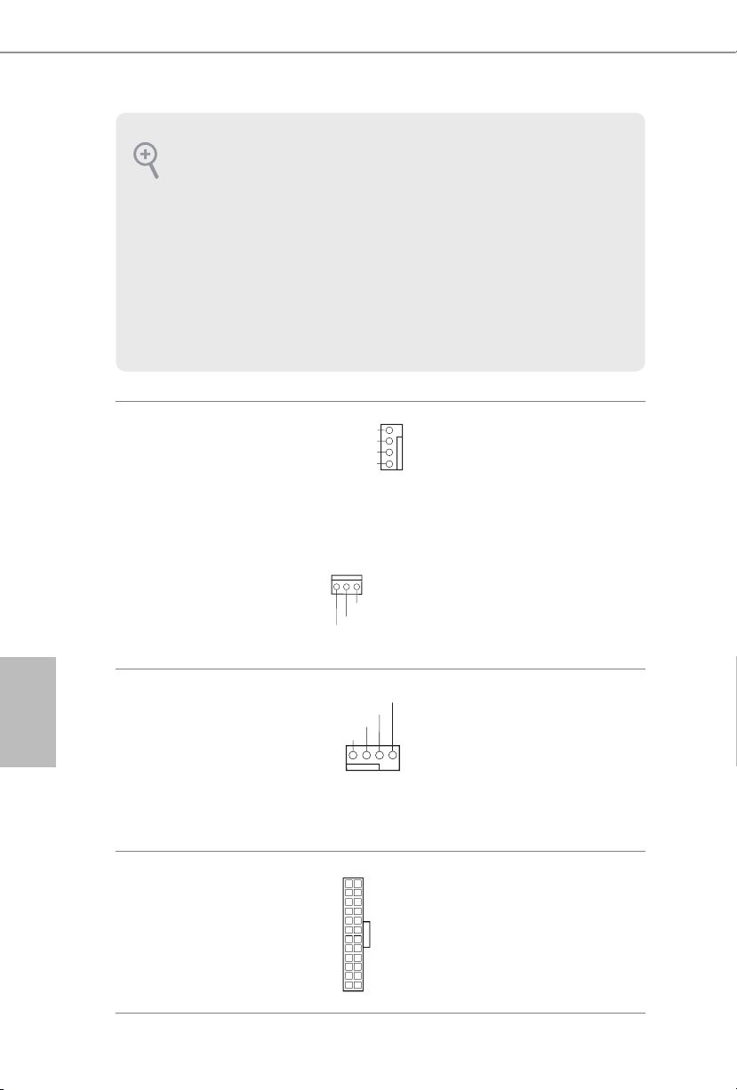
1. El Audio de Alta Denición (HDA, en inglés) es compatible con el método de sensor de
FAN_SPEED_CONTROL
FAN_SPEED_CONTROL
4
CHA_FAN_SPEED
conectores, sin embargo, el cable del panel del chasis deberá ser compatible con HDA
para que pueda funcionar correctamente. Siga las instrucciones que se indican en nuestro
manual y en el manual del chasis para instalar su sistema.
2. Si utiliza un panel de audio AC’97, colóquelo en el cabezal de audio del panel frontal
siguiendo los pasos que se describen a continuación:
A. Conecte Mic_IN (MIC) a MIC2_L.
B. Conecte Audio_R (RIN) a OUT2_R y Audio_L (LIN) a OUT2_L.
C. Conecte Ground (Conexión a tierra) (GND) a Ground (GND).
D. MIC_RET y OUT_RET se utilizan únicamente con el panel de audio HD. No es
necesario que los conecte en el panel de audio AC’97.
E. Para activar el micrófono frontal, vaya a la cha “micrófono frontal” (Front Mic) en el
panel de control de Realtek y ajuste el “Volumen de grabación” (Recording Volume).
Español
Conector del ventilador
del chasis
(CHA_FAN1 de
4 contactos)
(consulte la pág. 1, nº 18)
(CHA_FAN2 de
3 contactos)
(consulte la pág. 1, nº 15)
Conector del ventilador de
la CPU
(CPU_FAN1 de 4
contactos)
(consulte la pág. 1, nº 2)
Conector de alimentación
ATX
(ATXPWR1 de 24
contactos)
(consulte la pág. 1, nº 4)
FAN_SPEED
FAN_VOLTAGE
GND
GND
FAN_VOLTAGE
CPU_FAN_SPEED
FAN_VOLTAGE
GND
1 2 3 4
12
1
Conecte los cables del ventilador
3
a los conectores del ventilador
2
1
y haga coincidir el cable negro
con el contacto de conexión a
tierra.
Esta placa base contiene un
conector de ventilador
(ventilador silencioso) de CPU
de 4 contactos. Si tiene pensando
conectar un ventilador de CPU
de 3 contactos, conéctelo al
contacto 1-3.
24
Esta placa base contiene un
conector de alimentación ATX
de 24 contactos. Para utilizar
una toma de alimentación ATX
de 20 contactos, conéctela en los
13
contactos del 1 al 13.
70

X370M
1
Conector de alimentación
ATX de 12V
(ATX12V1 de 4 contactos)
(consulte la pág. 1, nº 1)
Cabezal de puerto serie
(COM1 de 9 contactos)
(consulte la pág. 1, nº 14)
RRXD1
DDTR#1
TTXD1
DDCD#1
DDSR#1
CCTS#1
RRTS#1
GND
Conecte una fuente de
alimentación ATX 12V en este
conector.
*El enchufe de la fuente de
alimentación encaja en este
conector en una única dirección.
Este cabezal COM1 admite un
módulo de puerto serie.
RRI#1
Español
71

Русский
1 Введение
Благодарим вас за приобретение надежной материнской платы ASRock X370M,
выпускаемой под постоянным строгим контролем компании ASRock. Эта материнская
плата обеспечивает великолепную производительность и отличается надежной
конструкцией в соответствии с требованиями компании ASRock в отношении
качества и долговечности.
По причине обновления спецификации на материнскую платформу и
программного обеспечения BIOS содержимое настоящего руководства может
быть изменено без предварительного уведомления. При изменении содержимого
настоящего руководства его обновленная версия будет доступна на веб-сайте
ASRock без предварительного уведомления. При необходимости технической
поддержки, связанной с материнской платой, посетите веб-сайт и найдите на
нем информацию о модели используемой вами материнской платы. На веб-сайте
ASRock также можно найти самый последний перечень поддерживаемых
VGA-карт и ЦП. Веб-сайт ASRock http://www.asrock.com.
1.1 Комплект поставки
Материнская плата X370M (форм-фактор Micro ATX)
•
Краткое руководство по установке ASRock X370M
•
Диск с ПО для ASRock X370M
•
1 x экран панели с портами ввода-вывода
•
2 x кабеля передачи данных Serial ATA (SATA) (приобретаются отдельно)
•
1 x Винт для гнезда M.2 (приобретаются отдельно)
•
72

1.2 Технические характеристики
Форм-фактор Micro ATX
Платформа
ЦП
Чипсет
Память
•
Схема на основе твердотельных конденсаторов
•
Поддерживаются процессоры AMD серии RyzenTM 2000, 3000,
•
4000 G и 5000 под сокет AM4
Система питания 6
•
Поддерживаются ЦП мощностью до 105Вт.
•
AMD Promontory X370
•
Двухканальная память DDR4
•
2 гнезда DDR4 DIMM
•
Процессоры AMD серии Ryzen (Vermeer) поддерживают
•
модули памяти DDR4 3200/2933/2667/2400/2133 с ECC и без
ECC, небуферизованной памяти*
Процессоры AMD серии Ryzen (Matisse) поддерживают
•
модули памяти DDR4 3200/2933/2667/2400/2133 с ECC и без
ECC, небуферизованной памяти*
Процессоры AMD серии Ryzen (Renoir) поддерживают
•
модули памяти DDR4 3200/2933/2667/2400/2133 с ECC и без
ECC, небуферизованной памяти*
Процессоры AMD серии Ryzen (Pinnacle Ridge)
•
поддерживают модули памяти DDR4 3200+(OC)/2933(OC)/
2667/2400/2133, ECC, non-ECC и Unbuered*
Процессоры AMD серии Ryzen (Picasso) поддерживают
•
модули памяти DDR4 2933/2667/2400/2133 с без ECC,
небуферизованной памяти*
Процессоры AMD серии Ryzen (Summit Ridge) поддерживают
•
модули памяти DDR4 3200+(OC)/2933(OC)/2667/2400/2133,
ECC, non-ECC и Unbuered*
Процессоры AMD серии Ryzen (Raven Ridge) поддерживают
•
модули памяти DDR4 3200+(OC)/2933/2667/2400/2133, non-
ECC и Unbuered*
*Для процессоров серии Ryzen (Picasso и Renoir) модуль памяти
ECC поддерживается только процессорами PRO.
* Дополнительная информация представлена в Списке
совместимой памяти (Memory Support List ) на веб-сайте
ASRock. (http://www.asrock.com/)
* Максимальные DDR4 UDIMM см на стр. 18. поддерживаемые
частоты
X370M
Русский
73

Максимальный объем ОЗУ: 32ГБ
•
Позолоченные (15мкм) контакты слотов DIMM
•
Русский
Слоты
расширения
Графическая
подсистема
ЦП серии AMD Ryzen (Vermeer, Matisse, Summit Ridge, Renoir
и Pinnacle Ridge)
1 слот PCI Express 3.0 x 16 (PCIE2: режим x 16)*
•
ЦП серии AMD Ryzen (Picasso, Raven Ridge)
1 слот PCI Express 3.0 x 16 (PCIE2: режим x 8)*
•
APU серии AMD Athlon 2xxGE
1 слот PCI Express 3.0 x 16 (PCIE2: режим x 4)*
•
* Поддерживаются в качестве загрузочных SSD-диски типа
NVMe
1 слот PCI Express 2.0 x 1
•
Встроенный видеоадаптер AMD RadeonTM серии Vega в
•
процессорах APU серии Ryzen*
*Фактическая поддержка зависит от процессора
DirectX 12, пиксельные шейдеры 5.0
•
Общий объем памяти по умолчанию 2 ГБ. Поддерживается
•
максимальный общий объем памяти до 16 ГБ.
* Для максимального общего объема памяти 16 ГБ требуется
установить системную память емкостью 32 ГБ.
Поддерживается HDMI 1.4 с максимальным разрешением до
•
4K x 2K (4096 x 2160) при частоте обновления 24 Гц
(3840 x 2160 при 30Гц)
Поддерживаются Auto Lip Sync, Deep Color (12 бит/цвет),
•
xvYCC и HBR (High Bit Rate Audio) через порт HDMI 1.4
(требуется соответствующий HDMI-монитор)
Поддерживается HDCP 1.4 через порт HDMI 1.4.
•
Поддержка воспроизведения Full HD 1080p Blu-ray (BD)
•
через порт HDMI 1.4
74
Звук
7.1-канальный звук высокой четкости (аудиокодек Realtek
•
ALC887)
Защита от перепадов напряжения в электрической сети
•
Конденсаторы для аудиосистем ELNA
•

LAN
Тыловые
порты
ввода-вывода
Запоминающие
устройства
PCIE x 1 Gigabit LAN 10/100/1000 Мбит/с
•
Realtek RTL8111H
•
Поддерживается пробуждение по ЛВС
•
Молниезащита и защита от электростатических разрядов
•
Поддерживается Energy Ecient Ethernet 802.3az
•
Поддерживается PXE
•
1 x порт PS/2 для мыши/клавиатуры
•
1 x порт HDMI
•
2 x порта USB 2.0 (с защитой от электростатических
•
разрядов)
4 x портов USB 3.2 Gen1 (с защитой от электростатических
•
разрядов)
1 x порт ЛВС RJ-45 с индикаторами («Активность/
•
Соединение» и «Скорость»)
Разъемы HD Audio: линейный вход / фронтальные АС /
•
микрофон
4 x порта SATA3 со скоростью передачи данных 6,0Гб/с,
•
поддержка RAID (RAID 0, RAID 1 и RAID 10), NCQ, AHCI и
«горячего подключения».
1 x слот Ultra M.2, поддерживает модуль M.2 SATA3 типа
•
2242/2260/2280 со скоростью обмена данными 6,0Гбит/
с с ключом М и модуль M.2 PCI Express до версии Gen3 x 4
(32Гбит/с с ЦП Vermeer, Matisse, Picasso, Summit Ridge, Raven
Ridge, Renoir и Pinnacle Ridge) или Gen3 x 2 (16Гбит/с с Ath-
lon 2xxGE)*
* Поддерживаются в качестве загрузочных SSD-диски типа
NVMe
* Поддерживается комплект ASRock U.2
X370M
Русский
Разъемы
1 x колодка СОМ-порта
•
1 x колодка с разъемами датчика вскрытия корпуса и
•
динамика
1 x разъем для вентилятора охлаждения ЦП, 4-контактный
•
* Разъем процессорного вентилятора поддерживает вентилятор
с потребляемым током не более 1А (12Вт).
2 x разъема для вентилятора корпуса (1 х 4-контактный,
•
1 х 3-контактный)
* Разъем корпусного вентилятора поддерживает вентилятор с
потребляемым током не более 1А (12Вт).
75

Параметры
BIOS
Контроль
оборудования
1 x разъем питания АТХ, 24-контактный
•
1 x разъем питания 12 В, 4-контактный
•
1 x аудиоразъем для передней панели
•
2 x колодки USB 2.0 (4 порта USB 2.0, с защитой от
•
электростатических разрядов)
1 x колодка USB 3.2 Gen1 (2 порта USB 3.2 Gen1) (с защитой от
•
электростатических разрядов)
AMI UEFI Legal BIOS с поддержкой графического интерфейса
•
Поддержка технологии «Plug and Play»
•
Совместимость с управлением энергопотреблением по
•
ACPI 5.1
Поддержка функции JumperFree
•
Поддерживается SMBIOS 2.3.
•
Регулировка напряжений DRAM
•
Датчик температуры процессора / корпуса
•
Тахометр вентилятора охлаждения процессора / корпуса
•
Тихая работа вентилятора охлаждения процессора / корпуса
•
Управление скоростью вращения вентилятора охлаждения
•
процессора / корпуса
Датчик вскрытия корпуса
•
Контроль напряжений: +12 В, +5 В, +3,3 В, Vcore
•
Русский
Microso® Windows® 10 64-разрядная / 11 64-разрядная
Операционные
•
* Summit Ridge официально Windows® 11 не поддерживают.
системы
FCC, CE
Сертификация
•
Совместимость с ErP/EuP (необходим блок питания,
•
соответствующий стандарту ErP/EuP)
* С дополнительной информацией об изделии можно ознакомиться на веб-сайте: http://www.asrock.com
Следует учитывать, что разгон процессора, включая изменение настроек BIOS,
применение технологии Untied Overclocking и использование инструментов разгона
независимых производителей, сопряжен с определенным риском. Разгон процессора
может снизить стабильность системы или даже привести к повреждению ее
компонентов и устройств. Разгон процессора осуществляется пользователем
на собственный риск и за собственный счет. Мы не несем ответственность за
возможный ущерб, вызванный разгоном процессора.
76

1.3 Установка перемычек
Установка перемычек показана на рисунке. При установке перемычки-колпачка
на контакты перемычка «замкнута». Если перемычка-колпачок на контакты не
установлена, перемычка «разомкнута».
X370M
Порта Сброс настроек
CMOS
(CLRCMOS1)
(см. стр. 1, № 16)
CLRCMOS1 используется для удаления данных CMOS. В памяти CMOS содержатся
такие данные о настройке системы, как системный пароль, дата, время и параметры
настройки системы. Чтобы сбросить и обнулить параметры системы на настройки
по умолчанию, выключите компьютер и извлеките вилку из розетки, а затем
колпачковой перемычкой замкните контакты на CLRCMOS1 на 3 секунды.
После сброса настроек CMOS не забудьте снять колпачковую перемычку. При
необходимости сбросить настройки CMOS сразу после обновления BIOS сначала
перезагрузите систему, а затем выключите компьютер перед сбросом настроек
CMOS.
Сброс настроек CMOS может привести к определению вскрытию корпуса. Чтобы
обнулить запись предыдущего определения вскрытия корпуса, используйте
параметр Clear Status (Обнулить состояние) BIOS.
2-контактная перемычка
Замкнута: Сброс настроек
CMOS
Разомкнута: По умолчанию
Русский
77
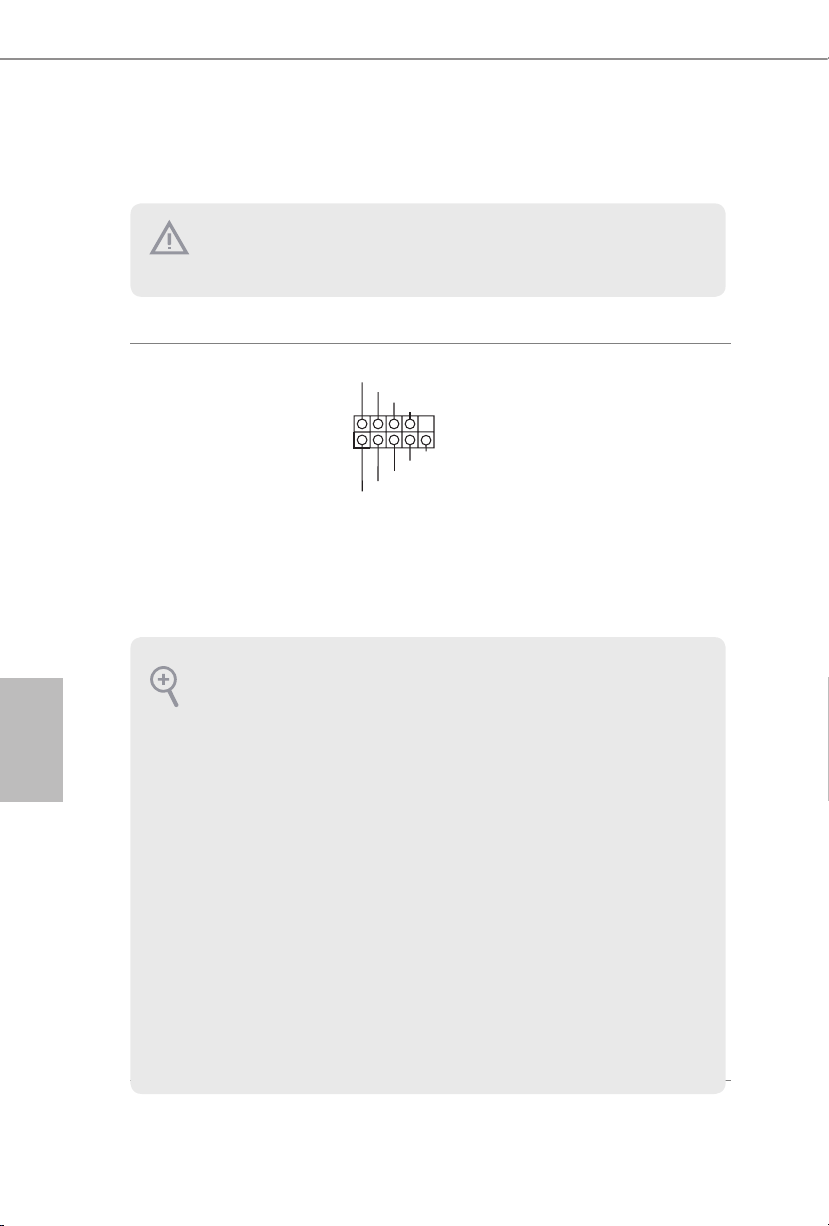
1.4 Колодки и разъемы, расположенные на системной
1
плате
Расположенные на системной плате колодки и разъемы НЕ являются
перемычками. НЕ устанавливайте на эти колодки и разъемы перемычкиколпачки. Установка перемычек-колпачков на эти колодки и разъемы может
вызвать неустранимое повреждение системной платы.
Русский
Колодка системной
панели
(9-контактная, PANEL1)
(см. стр. 1, № 12)
PWRBTN (кнопка питания):
Подключение кнопки питания, расположенной на передней панели корпуса. Можно
настроить способ выключения системы при нажатии кнопки питания.
RESET (кнопка сброса):
Подключение кнопки сброса, расположенной на передней панели корпуса. Нажмите
кнопку сброса, чтобы перезапустить компьютер, если он завис и нормальный
перезапуск невозможен.
PLED (светодиодный индикатор питания системы):
Подключение индикатора состояния, расположенного на передней панели корпуса.
Светодиодный индикатор горит, когда система работает. Когда система находится
в режиме ожидания S1/S3, светодиод мигает. Когда система находится в режиме
ожидания S4 или выключена (S5), светодиод не горит.
HDLED (светодиодный индикатор работы жесткого диска):
Подключение светодиодного индикатора работы жесткого диска, расположенного на
передней панели. Светодиодный индикатор горит, когда жесткий диск выполняет
считывание или запись данных.
Передняя панель может быть разной на разных корпусах. На передней панели
расположены кнопка питания, кнопка перезапуска, индикатор питания, индикатор
работы жесткого диска, динамик и т.д. При подключении передней панели к этой
колодке подключайте провода к соответствующим контактам.
PLED+
PLED-
HDLED-
HDLED+
PWRBTN#
GND
RESET#
GND
GND
Подключите расположенные
на корпусе кнопку питания,
кнопку перезагрузки и
индикатор состояния системы
к этой колодке в соответствии
с назначением контактов,
приведенным ниже. Перед
подключением кабелей
определите положительный и
отрицательный контакты.
78

X370M
DUMMY
GNDGND
+B
-B
+A
-A
USB_PWR
USB_PWR
1
1
+5V
DUMMY
SIGNAL
GND
DUMMY
SPEAKER
DUMMY
J_SENSE
OUT2_L
1
MIC_RET
PRESENCE#
GND
OUT2_R
MIC2_R
MIC2_L
OUT_RET
Колодка с разъемами
датчика вскрытия
корпуса и динамика
(7-контактный, SPK_CI1)
(см. стр. 1, № 13)
Разъемы Serial ATA3
(SATA3_1:
см. стр.1,№ 11)
(SATA3_2:
см. стр. 1, № 10)
(SATA3_3:
см. стр. 1, № 8)
(SATA3_4:
см. стр.1,№ 9)
Колодки USB 2.0
(9-контактная, USB_3_4)
(см. стр. 1, № 6)
(9-контактная, USB_5_6)
(см. стр. 1, № 7)
SATA3_3
SATA3_1
Предназначена для
подключения датчика
вскрытия корпуса и
корпусного динамика.
Эти четыре разъема
SATA3 предназначены для
подключения кабелей SATA
SATA3_4
внутренних запоминающих
устройств для передачи
данных со скоростью до
SATA3_2
6,0 Гбит/с.
На материнской плате имеется
две колодки. Каждая колодка
USB 2.0 поддерживает два
порта.
Колодки USB 3.2 Gen1
(19-контактная,
USB3_5_6)
(см. стр. 1, № 5)
Аудиоколодка передней
панели
(9-контактов, HD_
AUDIO1)
(см. стр. 1, № 17)
Vbus
IntA_PA_SSRX-
IntA_PA_SSRX+
IntA_PA_SSTX-
IntA_PA_SSTX+
IntA_PA_D-
IntA_PA_D+
VbusVbus
IntA_PB_SSRX-
IntA_PB_SSRX+
GND
IntA_PB_SSTX-
GND
IntA_PB_SSTX+
GND
IntA_PB_D-
GND
IntA_PB_D+
Dummy
1
На материнской плате имеется
одна колодка. Каждая колодка
USB 3.2 Gen1 поддерживает
два порта.
Русский
Эта колодка предназначена для
подключения аудиоустройств
к передней аудиопанели.
79

1. Аудиосистема высокого разрешения поддерживает функцию распознавания
FAN_SPEED_CONTROL
FAN_SPEED_CONTROL
4
CHA_FAN_SPEED
разъема, но для е правильной работы необходимо, чтобы провод панели корпуса
поддерживал передачу сигналов HDA. Инструкции по установке системы см. в
этом руководстве и руководстве на корпус.
2. При использовании аудиопанели AC’97 подключите ее к аудиоколодке передней
панели, как указано далее:
A. Подключите Mic_IN (MIC) к MIC2_L.
B. Подключите Audio_R (RIN) к OUT2_R, Audio_L (LIN) к OUT2_L.
C. Подключите провод заземления (GND) к контакту заземления (GND).
D. Контакты MIC_RET и OUT_RET используются только для аудиопанели
высокого разрешения. При использовании аудиопанели AC’97 их подключать не
нужно.
E. Чтобы активировать передний микрофон, перейдите на вкладку FrontMic панели управления Realtek и отрегулируйте параметр Recording Volume
(Громкость записи).
Русский
80
Разъем вентилятора
корпуса
(4-контакта, CHA_FAN1)
(см. стр. 1, № 18)
(3 контактов, CHA_FAN2)
(см. стр. 1, № 15)
Разъем вентилятора
охлаждения процессора
(4-контакта, CPU_FAN1)
(см. стр.1,№ 2)
Разъем питания АТХ
(24-контакта,
ATXPWR1)
(см. стр. 1, № 4)
FAN_SPEED
FAN_VOLTAGE
GND
GND
FAN_VOLTAGE
CPU_FAN_SPEED
FAN_VOLTAGE
GND
1 2 3 4
12
1
Предназначены для
3
подключения кабелей разъемов
2
1
вентиляторов и подключения
черного провода к заземлению.
Эта материнская плата снабжена
4-контактным разъемом для
малошумящего вентилятора
ЦП. Если вы собираетесь
подключить 3-контактный
вентилятор охлаждения
процессора, подключайте его к
контактам 1-3.
24
Эта материнская плата
оснащена 24-контактным
разъемом питания АТХ. Чтобы
использовать 20-контактный
разъем питания ATX,
13
подключите его вдоль контакта
1 и контакта 13.
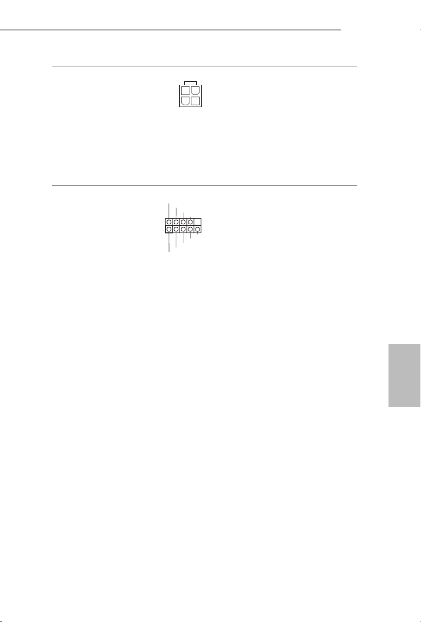
X370M
1
Разъем питания АТХ 12 В
(4-контактов, ATX12V1)
(см. стр. 1, № 1)
Колодка
последовательного порта
(9-контактная, COM1)
(см. стр. 1, № 14)
RRXD1
DDTR#1
TTXD1
DDCD#1
DDSR#1
CCTS#1
RRTS#1
GND
К данному разъему
подключается источник
питания ATX 12 В.
*Разъем от блока питания
подсоединяется к этому
разъему только в одной
ориентации.
Колодка COM1 поддерживает
подключение модуля
последовательного порта.
RRI#1
Русский
81

Português
1 Introdução
Obrigado por adquirir a placa mãe ASRock X370M, uma conável placa mãe ASRock
produzida sob rigoroso controle de qualidade consistente. Esta placa principal oferece um
excelente desempenho com um design robusto em conformidade com o compromisso da
ASRock em fabricar produtos de qualidade e resistentes.
Como as especicações da placa principal e o soware do BIOS poderão ser atualizados, o
conteúdo deste manual estará sujeito a alterações sem aviso prévio. No caso de ocorrerem
modicações neste manual, a versão atualizada estará disponível no site da ASRock sem
aviso prévio. Se precisar de assistência técnica relacionada a esta placa principal, visite o
nosso site para obter informações especícas sobre o modelo que estiver utilizando. Você
também poderá encontrar a lista de placas VGA e CPU mais recentes suportadas no site da
ASRock. Site da ASRock http://www.asrock.com.
1.1 Conteúdo da embalagem
Placa-mãe ASRock X370M (Micro ATX Form Factor)
•
Guia de Instalação Rápida ASRock X370M
•
CD de Suporte do ASRock X370M
•
1 x Painel de E/S
•
2 x Cabos de dados Serial ATA (SATA) (Opcional)
•
1 x Parafuso para Soquete M.2 (Opcional)
•
82

1.2 Especicações
Micro ATX Form Factor
Plataforma
CPU
Chipset
Memória
•
Design de condensador sólido
•
Suporta Desktop processadores AMD AM4 soquete RyzenTM série
•
2000, 3000, 4000 G e 5000
Design com 6 fases de alimentação
•
Suporta CPU até 105 W
•
AMD Promontory X370
•
Tecnologia de memória DDR4 de dois canais
•
2 x Slots DIMM DDR4
•
CPUs série AMD (Vermeer ) suporta DDR4 3200/2933/2667/
•
2400/2133 ECC & não-ECC, memória un-buered*
CPUs série AMD (Matisse) suporta DDR4 3200/2933/2667/
•
2400/2133 ECC & não-ECC, memória un-buered*
APUs série AMD (Renoir) suporta DDR4 3200/2933/2667/
•
2400/2133 ECC & não-ECC, memória un-buered*
CPUs série AMD Ryzen (Pinnacle Ridge) suporta DDR4
•
3200+(OC)/2933 (OC)/2667/2400/2133 ECC & não ECC, memória
un-buered*
CPUs série AMD (Picasso) suporta DDR4 2933/2667/2400/2133
•
não-ECC, memória un-buered*
CPUs série AMD (Summit Ridge) suporta DDR4 3200+(OC)/2933
•
(OC)/2667/2400/2133 ECC & não ECC, memória un-buered*
CPUs série AMD (Raven Ridge) suporta DDR4
•
3200+(OC)/2933/2667/2400/2133 não ECC, memória un-buered*
* Para CPUs série Ryzen (Picasso e Renoir), ECC só é suportado com
CPUs PRO.
* Por favor, consulte a Lista de Suporte de Memória no site da ASRock
para obter mais informação. (http://www.asrock.com/)
* Por favor consulte a página 18 para máxima DDR4 UDIMM.suporte
de frequência
Capacidade máxima da memória do sistema: 32 GB
•
Contato em Ouro 15μ nos slots DIMM
•
X370M
Português
83

Português
Slot de
expansão
Grácos
CPUs AMD Série Ryzen (Vermeer, Matisse, Summit Ridge, Renoir
e Pinnacle Ridge)
1 x Slot PCI Express 3.0 x 16 (PCIE2: x 16 modo)*
•
CPUs AMD Série Ryzen (Picasso, Raven Ridge)
1 x Slot PCI Express 3.0 x 16 (PCIE2: x 8 modo)*
•
APU AMD Athlon 2xxGE séries
1 x Slot PCI Express 3.0 x 16 (PCIE2: x 4 modo)*
•
* Suporta NVMe SSD nos discos de inicialização
1 x slots PCI Express 2.0 x 1
•
AMD RadeonTM Integrado Série Vega Grácas na Série Ryzen
•
APU*
* Suporte atual pode vairar por CPU
DirectX 12, Pixel Shader 5.0
•
Memória compartilhada padrão 2 GB. Memória compartilhada
•
máx suporta até 16 GB.
* A memória compartilhada máx de 16 GB requer 32 GB de memória
de sistema instalado.
Suporta HDMI 1.4 com resolução máx. até 4K x 2K (4096 x 2160)
•
@ 24Hz / (3840 x 2160) @ 30Hz
Suporta Auto sincronização labial, Deep Color (12bpc), xvYCC e
•
HBR (High Bit Rate Audio) com porta HDMI 1.4 (É necessário
um monitor compatível com HDMI)
Suporta HDCP 1.4 com Porta HDMI 1.4
•
Suporta reprodução Full HD 1080p Blu-ray (BD) com Porta
•
HDMI 1.4
84
Áudio
LAN
Áudio 7.1 CH HD com proteção de conteúdo (Codec de áudio
•
Realtek ALC887)
Suporta Proteção de Sobretensão
•
Fones de Áudio ELNA
•
LAN Gigabit 10/100/1000 Mb/s PCIE x 1
•
Realtek RTL8111H
•
Suporta Wake-On-LAN
•
Oferece Suporte à Proteção de Relâmpago/ESD
•
Suporta Energy Ecient Ethernet 802.3 az
•

E/S do painel
posterior
Armazenamento
Suporta PXE
•
1 x Porta PS/2 para mouse/teclado
•
1 x Porta HDMI
•
2 x Portas USB 2.0 (Suporta Proteção ESD)
•
4 x Portas USB 3.2 Gen1 (Suporta Proteção ESD)
•
1 x Porta LAN RJ-45 com LED (LED ACT/LINK e LED DE
•
VELOCIDADE)
Fichas de áudio HD: Entrada de Linha / Autofalante Frontal /
•
Microfone
4 x Conectores SATA3 6,0 Gb/s, suporta RAID (RAID 0, RAID 1,
•
e RAID 10), NCQ, AHCI e Conexão a Quente
1 x Soquete Ultra M.2, suporta M chave digite 2242/2260/2280
•
módulo M.2 SATA3 6,0 Gb/s e M.2 PCI Express até Gen3 x 4
(32 Gb/s) (com Vermeer, Matisse, Picasso, Summit Ridge, Raven
Ridge, Renoir e Pinnacle Ridge) ou Gen3 x 2 (16 Gb/s) (com
Athlon 2xxGE)*
* Suporta NVMe SSD nos discos de inicialização
* Suporta Kit U.2 ASRock
X370M
Conector
1 x Suporte porta COM
•
1 x Intrusão do Chassi e Cabeçote de Autofalante
•
1 x Conector da ventoinha da CPU (4 pinos)
•
* O Conector do Ventilador de CPU suporta o ventilador de CPU de
alimentação máxima 1A do ventilador (12 W).
2 x conectores ventilador chassis (1 x 4 pinos, 1 x 3 pinos)
•
* O Conector do Ventilador do Chassi suporta o ventilador do chassi
de potência do ventilador máxima de 1 A (12 W).
1 x Conector alimentação ATX 24 pinos
•
1 x Conector de energia 4 pinos 12 V
•
1 x Conector de áudio do painel frontal
•
2 x Plataformas USB 2.0 (Suporta 4 portas USB 2.0) (Suporta
•
Proteção ESD)
1 x Plataforma USB 3.2 Gen1 (Suporta 2 portas USB 3.2 Gen1)
•
(Suporta Proteção ESD)
Português
85

Português
AMI UEFI Legal BIOS com suporte GUI
Funções da
BIOS
Monitor de
hardware
SO
•
Suporta "Plug and Play"
•
ACPI 5.1 compatível com eventos de despertar
•
Suporta jumperfree
•
Suporte SMBIOS 2.3
•
Multi-ajuste de Voltagem da DRAM
•
Sensor de temperatura da CPU/Gabinete
•
Tacômetro da Ventoinha da CPU/Gabinete
•
Ventilador silencioso de CPU/Chassis
•
Controle de multi velocidade da Ventoinha da CPU/Gabinete
•
Detecção de ABERTURA da CAIXA
•
Monitoramento da tensão: +12V, +5V, +3,3V, Vcore
•
Microso® Windows® 10 64-bit / 11 64-bit
•
* Summit Ridge não suportam ocialmente o Windows® 11.
FCC, CE
Certicações
•
Preparada para ErP/EuP (é necessária uma fonte de alimentação
•
preparada para ErP/EuP)
* Para obter informações detalhadas sobre o produto, por favor, visite o nosso site: http://www.asrock.com
86
Por favor, observe que existe um certo risco envolvendo overclocking, incluindo o ajuste
das denições na BIOS, a aplicação de tecnologia Untied Overclocking ou a utilização de
ferramentas de overclocking de terceiros. O overclocking poderá afetar a estabilidade do
sistema ou mesmo causar danos nos componentes e dispositivos do seu sistema. Ele deve ser
realizado por sua conta e risco. Não nos responsabilizamos por possíveis danos causados
pelo overclocking.

1.3 Conguração dos jumpers
A imagem abaixo mostra como os jumpers são congurados. Quando a tampa do jumper é
colocada nos pinos, o jumper é "Curto". Se não for colocada uma tampa de jumper nos pinos,
o jumper é "Aberto".
X370M
Apagar o Header CMOS
(CLRCMOS1)
(ver p.1, N.º 16)
CLRCMOS1 permite que você apague os dados no CMOS. Os dados no CMOS incluem
informações de conguração do sistema, tal como senha do sistema, data, hora e
parâmetros de conguração do sistema. Para apagar e reinicializar os parâmetros do sistema
na conguração padrão, desligue o computador e retire o cabo de alimentação, utilizando
em seguida a tampa do jumper nos pinos de CLRCMOS1 durante 3 segundos. Por favor,
não se esqueça de retirar a tampa do jumper depois de apagar o CMOS. Se você precisar
apagar o CMOS logo após ter terminado uma atualização da BIOS, deverá primeiro iniciar
o sistema e voltar a encerrá-lo antes de apagar o CMOS.
Se você apagar o CMOS, poderá ser detectada a abertura da caixa. Ajuste a opção do BIOS
"Limpar estado" para limpar o registo anterior de estado de intrusão no chassis.
Jumper de 2 pinos
Curto: Apagar CMOS
Abrir: Padrão
Português
87
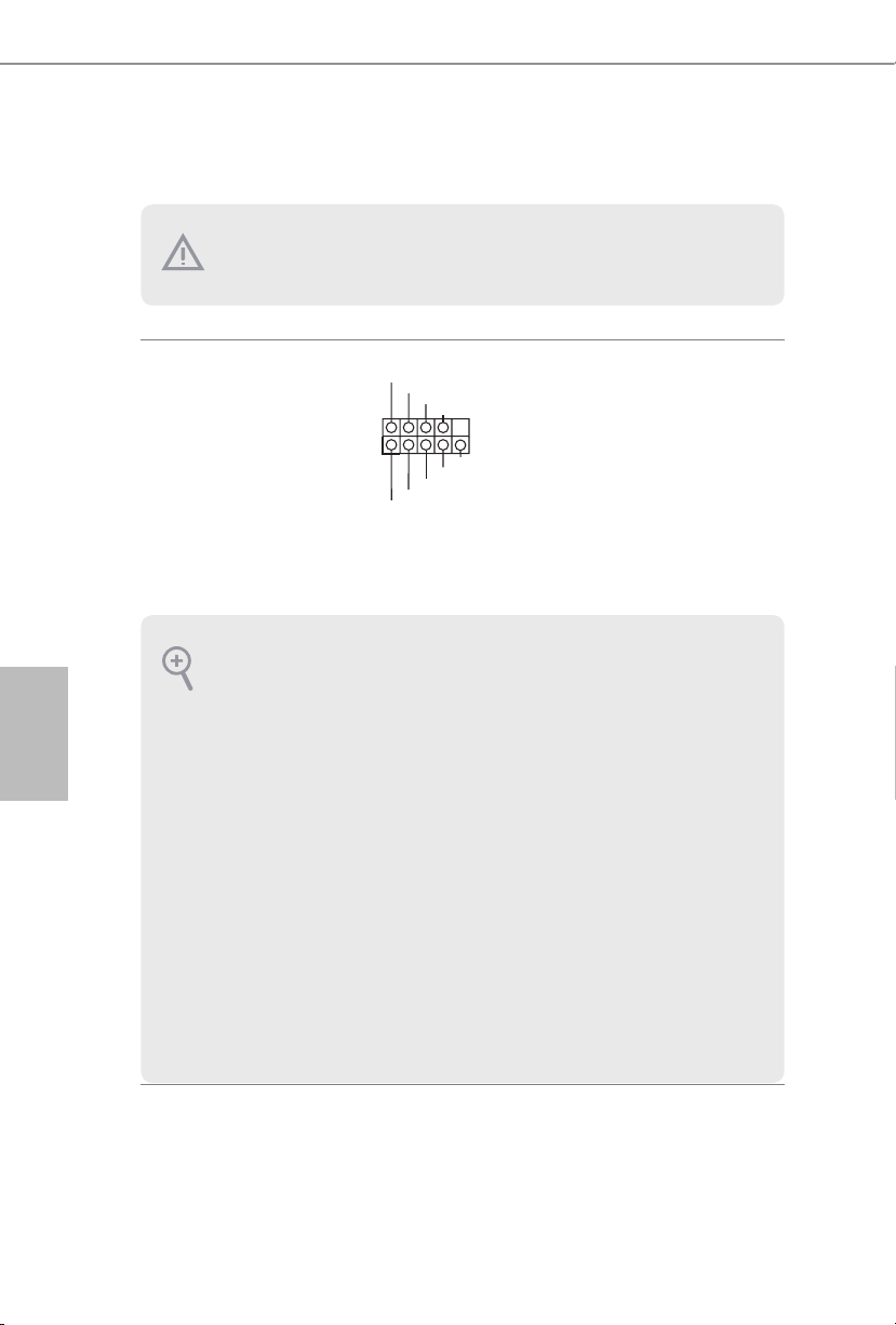
1.4 Suportes e conectores onboard
1
Os conectores e suportes onboard NÃO são jumpers. NÃO coloque tampas de jumpers sobre
estes terminais e conectores. Colocar tampas de jumpers sobre os terminais e conectores irá
causar danos permanentes à placa-mãe.
Português
Suporte do painel de sistema
(PAINEL1 de 9 pinos)
(ver p.1, N.º 12)
PWRBTN (Botão de alimentação):
Conecte o botão de alimentação no painel frontal do chassi. Você pode congurar a forma para
desligar o seu sistema através do botão de alimentação.
RESET (Botão de reinicialização):
Conecte o botão de reinicialização no painel frontal do chassi. Pressione o botão de reinicialização para reiniciar o computador, se ele congela e falha ao realizar um reinício normal.
PLED (LED de alimentação do sistema):
Conecte o indicador do estado da alimentação no painel frontal do chassi. O LED cará aceso
quando o sistema estiver em funcionamento. O LED cará piscando quando o sistema estiver
nos estados de suspensão S1/S3. O LED cará desligado quando o sistema estiver no estado de
suspensão S4 ou desligado (S5).
HDLED (LED de atividade do disco rígido):
Conecte o LED de atividade do disco rígido no painel frontal do chassi. O LED cará aceso
quando o disco rígido estiver lendo ou registrando dados.
O design do painel frontal poderá variar dependendo do chassi. Um módulo de painel frontal
consiste principalmente em um botão de alimentação, um botão de reinicialização, um LED de
alimentação, um LED de atividade do disco rígido, um alto-falante, etc. Ao conectar seu
módulo de painel frontal do chassi a este conector, certique-se de que os os e os pinos
correspondem de forma correta.
PLED+
PLED-
HDLED-
HDLED+
PWRBTN#
GND
RESET#
GND
GND
Ligue o botão de alimentação,
o botão de reinicialização e o
indicador do estado do sistema
no chassi deste suporte, de
acordo com a descrição abaixo.
Observe os pinos positivos e
negativos antes de conectar os
cabos.
88

X370M
DUMMY
GNDGND
+B
-B
+A
-A
USB_PWR
USB_PWR
1
1
+5V
DUMMY
SIGNAL
GND
DUMMY
SPEAKER
DUMMY
J_SENSE
OUT2_L
1
MIC_RET
PRESENCE#
GND
OUT2_R
MIC2_R
MIC2_L
OUT_RET
Intrusão do Chassi e
Cabeçote de Autofalante
(SPK_CI1 de 7 pinos)
(ver p.1, N.º 13)
Conectores série ATA3
(SATA3_1:
ver p.1, N.º 11)
(SATA3_2:
ver p.1, N.º 10)
(SATA3_3:
ver p.1, N.º 8)
(SATA3_4:
ver p.1, N.º 9)
Plataformas USB 2.0
(USB_3_4 de 9 pinos)
(ver p.1, N.º 6)
(USB_5_6 de 9 pinos)
(ver p.1, N.º 7)
SATA3_3
SATA3_1
Conecte a instrusão do chassi
e autofalante do chassi a este
cabeçote.
Estes quatro conectores SATA3
suportam cabos de dados SATA
para dispositivos de
SATA3_4
armazenamento interno com
uma taxa de transferência de
dados de até 6,0 Gb/s.
SATA3_2
Há dois cabeçotes nesta
placa-mãe. Cada suporte USB 2.0
pode suportar duas portas.
Português
Plataforma USB 3.2 Gen1
(USB3_5_6 de 19 pinos)
(ver p.1, N.º 5)
Suporte de áudio do painel
frontal
(HD_AUDIO1 de 9 pinos)
(ver p.1, N.º 17)
Vbus
IntA_PA_SSRX-
IntA_PA_SSRX+
IntA_PA_SSTX-
IntA_PA_SSTX+
IntA_PA_D-
IntA_PA_D+
VbusVbus
IntA_PB_SSRX-
IntA_PB_SSRX+
GND
IntA_PB_SSTX-
GND
IntA_PB_SSTX+
GND
IntA_PB_D-
GND
IntA_PB_D+
Dummy
1
Há um cabeçote nesta placa-mãe.
Cada suporte USB 3.2 Gen1 pode
suportar duas portas.
Este suporte destina-se à conexão
dos dispositivos de áudio no
painel de áudio frontal.
89

1. O Áudio de alta denição suporta Sensor de Adaptador, mas o o do painel no chassi
FAN_SPEED_CONTROL
FAN_SPEED_CONTROL
4
CHA_FAN_SPEED
deverá suportar HDA para funcionar corretamente. Por favor, siga as instruções no
nosso manual e no manual do chassi para instalar o seu sistema.
2. Se utilizar um painel de áudio AC’97, instale-o no terminal de áudio do painel frontal de
acordo com os passos abaixo:
A. Ligue Mic_IN (MIC) a MIC2_L.
B. Conecte o Audio_R (RIN) a OUT2_R e Audio_L (LIN) a OUT2_L.
C. Conecte a ligação Terra (GND) à Terra (GND).
D. MIC_RET e OUT_RET destinam-se apenas ao painel de áudio HD. Você não precisa
ligá-los ao painel de áudio AC’97.
E. Para ativar o microfone frontal, vá à guia “Microfone Frontal” no painel de controle
Realtek e ajuste o “Volume de gravação”.
Português
Conector do ventilador do
chassi
(CHA_FAN1 de 4 pinos)
(ver p.1, N.º 18)
(CHA_FAN2 de 3 pinos)
(ver p.1, N.º 15)
Conector da Ventoinha da
CPU
(CPU_FAN1 de 4 pinos)
(ver p.1, N.º 2)
Conector de alimentação
ATX
(ATXPWR1 de 24 pinos)
(ver p.1, N.º 4)
FAN_SPEED
FAN_VOLTAGE
GND
GND
FAN_VOLTAGE
CPU_FAN_SPEED
FAN_VOLTAGE
GND
1 2 3 4
12
1
Por favor, conecte os cabos do
3
ventilador aos conectores do
2
1
ventilador e corresponda o o
preto no pino terra.
Esta placa mãe inclui um
conector de ventilador da CPU
(Ventilador silencioso) de
4 pinos. Se você pretende
conectar um ventilador da CPU
de 3 pinos, por favor, conecte-o
ao Pino 1-3.
24
Esta placa-mãe inclui um
conector de alimentação ATX de
24 pinos. Para utilizar uma fonte
de alimentação ATX de 20 pinos,
13
introduza-a no Pino 1 e Pino 13.
90

X370M
1
Conector de alimentação
de 12V ATX
(ATX12V1 de 4 pinos)
(ver p.1, N.º 1)
Suporte da porta serial
(COM1 de 9 pinos)
(ver p.1, N.º 14)
RRXD1
DDTR#1
TTXD1
DDCD#1
DDSR#1
CCTS#1
RRTS#1
GND
Por favor, ligue este conector a
uma alimentação de força ATX
12V.
*O plugue de sua fonte de
alimentação se encaixa neste
conector apenas em uma
orientação.
Este suporte COM1 recebe um
módulo da porta serial.
RRI#1
Português
91

1 Wprowadzenie
Dziękujemy za zakupienie płyty głównej ASRock X370M, niezawodnej płyty głównej
produkowanej z konsekwentnie wykonywaną przez rmę ASRock, rygorystyczną kontrolą
jakości. Płyta ta zapewnia doskonałą jakość działania i solidną konstrukcję, spełniającą
zobowiązanie rmy ASRock do dostarczania produktów o wysokiej jakości i wytrzymałości.
Ponieważ specykacje płyty głównej i oprogramowanie BIOS mogą zostać zaktualizowane,
zawartość tego podręcznika może zostać zmieniona bez powiadomienia. W przypadku
jakichkolwiek modykacji tego podręcznika, zaktualizowana wersja będzie dostępna na
stronie internetowej ASRock, bez dalszego powiadomienia. Jeśli wymagana jest pomoc
techniczna w odniesieniu do tej płyty głównej, należy odwiedzić stronę internetową w celu
uzyskania specycznych informacji o używanym modelu. Na stronie internetowej ASRock,
można także pobrać listę najnowszych kart VGA i obsługiwanych CPU. Strona internetowa
ASRock http://www.asrock.com.
1.1 Zawartość opakowania
Płyta główna ASRock X370M (Współczynnik kształtu Micro ATX)
Polski
•
Skrócona instrukcja instalacji ASRock X370M
•
Pomocnicza płyta CD ASRock X370M
•
1 x osłona panelu Wejścia/Wyjścia
•
2 x kable danych Serial ATA (SATA) (Opcjonalne)
•
1 x śruba do gniazda M.2 (Opcjonalna)
•
92

1.2 Specykacje
Platforma
CPU
Chipset
Pamięć
•
•
•
•
•
•
•
•
•
•
•
•
•
•
•
* Dla serii CPU Ryzen (Picasso i Renoir), ECC jest obsługiwana tylko
z CPU PRO.
* Sprawdź listę obsługiwanej pamięci na stronie internetowej ASRock
w celu uzyskania dalszych informacji. (http://www.asrock.com/)
* Sprawdź stronę 18 w celu uzyskania informacji o maksymalnej
DDR4 UDIMM.obsługiwanej częstotliwości.
•
•
Współczynnik kształtu Micro ATX
Konstrukcja kondensatorami stałymi
Obsługa procesorów serii AMD AM4 Socket RyzenTM 2000, 3000,
4000 G i 5000
Sekcja zasilania 6 Power Phase Design
Obsługa CPU do 105W
AMD Promontory X370
Technologia pamięci Dual Channel DDR4
2 x gniazda DDR4 DIMM
Seria CPU AMD Ryzen (Vermeer) z obsługą DDR4 3200/2933/
2667/2400/2133 ECC i nie-ECC, pamięć niebuforowana*
Seria CPU AMD Ryzen (Matisse) z obsługą DDR4 3200/2933/
2667/2400/2133 ECC i nie-ECC, pamięć niebuforowana*
Seria APU AMD Ryzen (Renoir) z obsługą DDR4 3200/2933/
2667/2400/2133 ECC i nie-ECC, pamięć niebuforowana*
Seria CPU AMD Ryzen (Pinnacle Ridge) z obsługą DDR4 3200+
(OC)/2933(OC)/2667/2400/2133 ECC i nie-ECC, pamięć
niebuforowana*
Seria CPU AMD Ryzen (Picasso) z obsługą DDR4 2933/2667/
2400/2133 nie-ECC, pamięć niebuforowana*
Seria CPU AMD Ryzen (Summit Ridge) z obsługą DDR4 3200+
(OC)/2933(OC)/2667/2400/2133 ECC i nie-ECC, pamięć
niebuforowana*
Seria CPU AMD Ryzen (Raven Ridge) z obsługą DDR4 3200+
(OC)/2933/2667/2400/2133 nie-ECC, pamięć niebuforowana*
Maks. wielkość pamięci systemowej: 32GB
15μ pozłacane styki w gniazdach DIMM
X370M
Polski
93

Gniazdo
rozszerzenia
Graka
Polski
Procesor serii AMD Ryzen (Vermeer, Matisse, Summit Ridge ,
Renoir oraz Pinnacle Ridge)
1 x gniazdo PCI Express 3.0 x 16 (tryb PCIE2: x 16)*
•
Procesor serii AMD Ryzen (Picasso, Raven Ridge)
1 x gniazdo PCI Express 3.0 x 16 (tryb PCIE2: x 8)*
•
APU serii AMD Athlon 2xxGE
1 x gniazdo PCI Express 3.0 x 16 (tryb PCIE2: x 4)*
•
* Obsługa SSD NVMe, jako dysków rozruchowych
1 x gniazdo PCI Express 2.0 x 1
•
Zintegrowana karta graczna AMD RadeonTM serii Vega w APU
•
serii Ryzen*
* Rzeczywista obsługa zależy od CPU
DirectX 12, Pixel Shader 5.0
•
Pamięć współdzielona, domyślnie 2GB. Maksymalnie pamięć
•
współdzielona obsługuje do 16GB.
* Maksymalna pamięć współdzielona 16GB wymaga zainstalowania
32GB pamięci systemowej.
Obsługa HDMI 1.4 z maks. rozdzielczością do 4K x 2K
•
(4096 x 2160) przy 24Hz / (3840 x 2160) przy 30Hz
Obsługa Auto Lip Sync, Deep Color (12bpc), xvYCC i HBR (High
•
Bit Rate Audio) z portami HDMI 1.4 (Wymagany monitor zgodny
z HDMI)
Obsługa HDCP 1.4 z portem HDMI 1.4
•
Obsługa odtwarzania Blu-ray (BD) Full HD 1080p z portem
•
HDMI 1.4
94
Audio
LAN
Dźwięk HD 7.1 CH (kodek audio Realtek ALC887)
•
Obsługa zabezpieczenia przed przepięciami
•
Nasadki audio ELNA
•
1 x PCIE Gigabit LAN 10/100/1000 Mb/s
•
Realtek RTL8111H
•
Obsługa Wake-On-LAN
•
Obsługa zabezpieczenia przed wyładowaniami atmosferycznymi/
•
ESD
Obsługa Energy Ecient Ethernet 802.3az
•
Obsługa PXE
•

Tylny panel
Wejścia/
Wyjścia
Przechowywanie
Złącze
1 x port myszy/klawiatury PS/2
•
1 x port HDMI
•
2 x porty USB 2.0 (Obsługa zabezpieczenia ESD)
•
4 x porty USB 3.2 Gen1 (Obsługa zabezpieczenia ESD)
•
1 x port LAN RJ-45 z LED (LED ACT/LINK i LED SPEED)
•
Gniazda audio HD: Wejście liniowe / Głośnik przedni / Mikrofon
•
4 x złącza SATA3 6,0 Gb/s, obsługa RAID (RAID 0, RAID 1 i
•
RAID 10), NCQ, AHCI i Hot Plug
1 x gniazdo Ultra M.2, obsługa M Key typu 2242/2260/2280
•
modułu M.2 SATA3 6,0 Gb/s i modułu M.2 PCI Express do Gen3
x 4 (32 Gb/s) (z Vermeer, Matisse, Picasso, Summit Ridge, Raven
Ridge, Renoir oraz Pinnacle Ridge) lub Gen3 x 2 (16 Gb/s) (z
Athlon 2xxGE APU)*
* Obsługa SSD NVMe, jako dysków rozruchowych
* Obsługa ASRock U.2 Kit
1 x złącze główkowe portu COM
•
1 x złącze główkowe naruszenia obudowy i głośnika
•
1 x złącze wentylatora CPU (4-pinowe)
•
* Złącze wentylatora CPU obsługuje wentylator CPU maksymalnym
prądem zasilania wentylatora 1A (12W).
2 x złącze wentylatora obudowy (1 x 4-pinowe, 1 x 3-pinowe)
•
* Złącze wentylatora obudowy obsługuje wentylator obudowy
maksymalnym prądem zasilania wentylatora 1 A (12 W).
1 x 24 pinowe złącze zasilania ATX
•
1 x 4 pinowe złącze zasilania 12 V
•
1 x złącze audio na panelu przednim
•
2 x złącza główkowe USB 2.0 (Obsługa 4 portów USB 2.0)
•
(Obsługa zabezpieczenia ESD)
1 x porty główkowe USB 3.2 Gen1 (obsługa 2 portów USB 3.2
•
Gen1) (obsługa zabezpieczenia ESD)
X370M
Polski
Funkcja
BIOS
Obsługa starszych wersji BIOS AMI UEFI z GUI
•
Obsługa “Plug and Play”
•
Zgodność zdarzeń wybudzania z ACPI 5.1
•
Obsługa bezzworkowa
•
Obsługa SMBIOS 2.3
•
Wielokrotna regulacja napięcia DRAM
•
95

Monitor
sprzętu
System
operacyjny
Certykaty
Wykrywanie temperatury procesora/obudowy
•
Tachometr wentylatora procesora/obudowy
•
Cichy wentylator procesora/obudowy
•
Sterowanie wieloma prędkościami obrotowymi wentylatora
•
procesora/obudowy
Wykrywanie OTWARCIA OBUDOWY
•
Monitorowanie napięcia: Napięcie rdzenia Vcore +12 V, +5 V,
•
+3,3 V
Microso® Windows® 10 64-bitowy / 11 64-bitowy
•
* Summit Ridge ocjalnie nie wspierają Windows® 11.
FCC, CE
•
Gotowość do obsługi ErP/EuP (Wymagane zasilanie z gotowością
•
obsługi ErP/EuP)
Polski
* Dla uzyskania szczegółowej informacji o produkcie, należy odwiedzić naszą stronę internetową:
http://www.asrock.com
Należy pamiętać, że przetaktowywanie jest związane z pewnym ryzykiem, włącznie z
regulacją ustawień w BIOS, zastosowaniem Untied Overclocking Technology lub
używaniem narzędzi przetaktowywania innych rm. Przetaktowywanie może wpływać na
stabilność systemu lub nawet powodować uszkodzenie komponentów i urządzeń systemu.
Powinno to zostać zrobione na własne ryzyko i koszt. Nie odpowiadamy za możliwe
uszkodzenia spowodowane przetaktowywaniem.
96
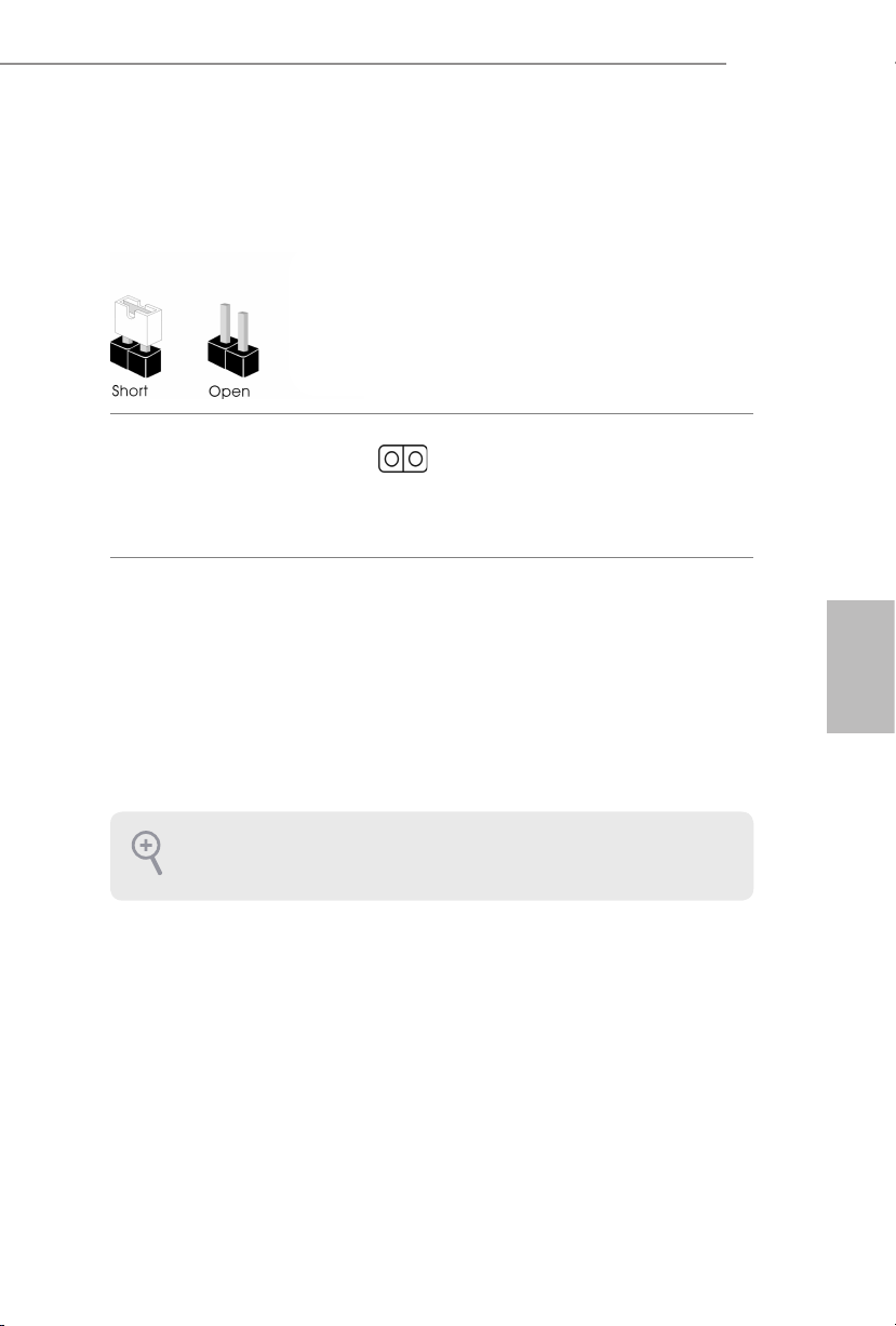
1.3 Ustawienia zworek
Ta ilustracja pokazuje ustawienia zworek. Po umieszczeniu nasadki zworki na pinach, zworka
jest “Zwarta”. Jeśli nasadka zworki nie jest umieszczona na pinach, zworka jest “Otwarta”.
X370M
Główkowe usuwania
pamięci CMOS
(CLRCMOS1)
(sprawdź s.1, Nr 16)
CLRCMOS1 umożliwia usunięcie wszystkich danych z pamięci CMOS. Dane w pamięci
CMOS obejmują informacje o konguracji systemu, takie jak hasło do systemu, datę, czas
i parametry konguracji systemu. W celu usunięcia i zresetowania parametrów systemu
do ustawień domyślnych, wyłącz komputer i odłącz przewód zasilający, a następnie użyj
nasadkę zworki do zwarcia na 3 sekundy pinów CLRCMOS1. Należy pamiętać, aby po
usunięciu danych z pamięci CMOS zdjąć nasadkę zworki. Jeśli wymagane jest usunięcie
danych z pamięci CMOS po zakończeniu aktualizacji BIOS, przed rozpoczęciem usuwania
danych z pamięci CMOS należy najpierw uruchomić system, a następnie wyłączyć go.
Po usunięciu danych z pamięci CMOS, może być wykrywane otwarcie obudowy. Wyreguluj
opcję BIOS “Clear Status (Stan usuwania)”, aby usunąć zapis poprzedniego stanu
naruszenia obudowy.
2-pinowa zworka
Zwarcie: Usunięcie danych z
pamięci CMOS
Otwarcie: Domyślne
Polski
97
 Loading...