


Version 1.0
Published October 2019
Copyright©2019 ASRock INC. All rights reserved.
Copyright Notice:
No part of this documentation may be reproduced, transcribed, transmitted, or
translated in any language, in any form or by any means, except duplication of
documentation by the purchaser for backup purpose, without written consent of
ASRock Inc.
Products and corporate names appearing in this documentation may or may not
be registered trademarks or copyrights of their respective companies, and are used
only for identication or explanation and to the owners’ benet, without intent to
infringe.
Disclaimer:
Specications and information contained in this documentation are furnished for
informational use only and subject to change without notice, and should not be
constructed as a commitment by ASRock. ASRock assumes no responsibility for
any errors or omissions that may appear in this documentation.
With respect to the contents of this documentation, ASRock does not provide
warranty of any kind, either expressed or implied, including but not limited to
the implied warranties or conditions of merchantability or tness for a particular
purpose.
In no event shall ASRock, its directors, ocers, employees, or agents be liable for
any indirect, special, incidental, or consequential damages (including damages for
loss of prots, loss of business, loss of data, interruption of business and the like),
even if ASRock has been advised of the possibility of such damages arising from any
defect or error in the documentation or product.
is device complies with Part 15 of the FCC Rules. Operation is subject to the following
two conditions:
(1) this device may not cause harmful interference, and
(2) this device must accept any interference received, including interference that
may cause undesired operation.
CALIFORNIA, USA ONLY
e Lithium battery adopted on this motherboard contains Perchlorate, a toxic substance
controlled in Perchlorate Best Management Practices (BMP) regulations passed by the
California Legislature. When you discard the Lithium battery in California, USA, please
follow the related regulations in advance.
“Perchlorate Material-special handling may apply, see www.dtsc.ca.gov/hazardouswaste/
perchlorate”
ASRock Website: http://www.asrock.com

AUSTRALIA ONLY
Our goods come with guarantees that cannot be excluded under the Australian Consumer
Law. You are entitled to a replacement or refund for a major failure and compensation for
any other reasonably foreseeable loss or damage caused by our goods. You are also entitled
to have the goods repaired or replaced if the goods fail to be of acceptable quality and the
failure does not amount to a major failure. If you require assistance please call ASRock Tel
: +886-2-28965588 ext.123 (Standard International call charges apply)

CE Warning
is device complies with directive 2014/53/EU issued by the Commision of the European
Community.
is equipment complies with EU radiation exposure limits set forth for an uncontrolled
environment.
is equipment should be installed and operated with minimum distance 20cm between
the radiator & your body.
Operations in the 5.15-5.35GHz band are restricted to indoor usage only.
Radio transmit power per transceiver type
Function Frequency Maximum Output Power (EIRP)
2400-2483.5 MHz 18.5 + / -1.5 dbm
5150-5250 MHz 21.5 + / -1.5 dbm
WiFi
Bluetooth 2400-2483.5 MHz 8.5 + / -1.5 dbm
5250-5350 MHz
5470-5725 MHz
18.5 + / -1.5 dbm (no TPC)
21.5 + / -1.5 dbm (TPC)
25.5 + / -1.5 dbm (no TPC)
28.5 + / -1.5 dbm (TPC)


Motherboard Layout
ATXP WR 1
Intel
X299
ATX12V2
PCI E1
Top:
Central/Bass
Center :
REAR SPK
Top:
LINE IN
Center :
FRONT
Bottom :
Optica l
SPDIF
Bottom :
MIC IN
PCI E3
USB3_4
1
1
USB5_6
1
HD_AUDI O1
PCI E5
SATA3_2_3
SATA3_4_5
PCI E4
CPU_FAN1
RoH S
SATA3_6_7
CLRC
BTN1
SATA3_0_1
DDR4 _B2 (64 bit , 28 8-pi n mo dul e)
DDR4 _B1 (64 bit , 28 8-pi n mo dul e)
DDR4 _A2 (64 bit , 28 8-pi n mo dul e)
DDR4 _A1 (64 bit , 28 8-pi n mo dul e)
CLRMOS1
1
M2_ WI FI_ 1
TBT_ M2_1
DDR4 _C1 (64 bit , 28 8-pi n mo dul e)
DDR4 _C2 (64 bit , 28 8-pi n mo dul e)
DDR4 _D1 (64 bit , 28 8-pi n mo dul e)
DDR4 _D2 (64 bit , 28 8-pi n mo dul e)
BIOS_A_LED 1
BIOS_B_LED 1
206 6 S ock et
Dr.
Deb ug
1
SPK_PLE D1
M2_1
M2_3
M2_2
SATA3_A1_ A2
1
USB3_5 _6
RGB_HEA DER1
1
RGB_HEAD ER2
1
PCI E2
CHA_FAN2 /
W_PUMP
Puri ty
Soun d 4
TM
Powe r
ADDR_LE D1
1
ADDR_LED 2
1
VROC1
1
ATX12V1
CPU_FAN2
/WP
CHA_FAN3
/WP
CHA_FAN1
/WP
USB32_T C1
1
SPI_TPM _J1
BIOS_A1
BIOS_B1
BIOS
BIOS
HDLED R ESET
PLED PWRBTN
PANEL1
1
CHA_FAN4
/WP
CHA_FAN5
/WP
USB 3.2 G en1
T:U SB3_1
B: USB3 _2
USB 2. 0
T:U SB2_ 1
B: USB 2_2
USB 3.2 G en1
T:U SB3_3
B: USB3 _4
Top:
10GLAN
(AQUANTIA
AQC107)
Top:
RJ-45
(I219V )
X299 CREATO R
TBT_ M2_2
X299 Creator
English
1

English
2
No. Description
1 2 x 288-pin DDR4 DIMM Slots (DDR4_A1, DDR4_B1)
2 2 x 288-pin DDR4 DIMM Slots (DDR4_A2, DDR4_B2)
3 ATX 12V Power Connector (ATX12V2)
4 ATX 12V Power Connector (ATX12V1)
5 Addressable LED Header (ADDR_LED2)
6 2 x 288-pin DDR4 DIMM Slots (DDR4_C2, DDR4_D2)
7 2 x 288-pin DDR4 DIMM Slots (DDR4_C1, DDR4_D1)
8 RGB LED Header (RGB_HEADER2)
9 ATX Power Connector (ATXPWR1)
10 Chassis / Waterpump Fan Connector (CHA_FAN1/WP)
11 CPU / Waterpump Fan Connector (CPU_FAN2/WP)
12 Front Panel Type C USB 3.2 Gen2 Header (USB32_TC1)
13 CPU Fan Connector (CPU_FAN1)
14 USB 3.2 Gen1 Header (USB3_5_6)
15 SATA3 Connectors (SATA3_0_1)
16 SATA3 Connectors (SATA3_2_3)
17 SATA3 Connectors (SATA3_4_5)
18 SATA3 Connectors (SATA3_6_7)
19 SATA3 Connectors (SATA3_A1_A2)
20 SPI TPM Header (SPI_TPM_J1)
21 Power LED and Speaker Header (SPK_PLED1)
22 System Panel Header (PANEL1)
23 Power Button (PWRBTN1)
24 Reset Button (RSTBTN1)
25 Chassis / Waterpump Fan Connector (CHA_FAN2/WP)
26 Clear CMOS Jumper (CLRMOS1)
27 Chassis / Waterpump Fan Connector (CHA_FAN3/WP)
28 Chassis / Waterpump Fan Connector (CHA_FAN4/WP)
29 USB 2.0 Header (USB5_6)
30 USB 2.0 Header (USB3_4)
31 Addressable LED Header (ADDR_LED1)
32 RGB LED Header (RGB_HEADER1)
33 Virtual RAID On CPU Header (VROC1)
34 Chassis / Waterpump Fan Connector (CHA_FAN5/WP)
35 Front Panel Audio Header (HD_AUDIO1)

I/O Panel
X299 Creator
5
3
6
1
2
4
1314
No. Description No. Description
1 LAN RJ-45 Port (Intel® I219V)* 8 USB 3.2 Gen2 underboltTM 3 Type-C Ports
2 10G LAN RJ-45 Port 9 Microphone (Pink)
(AQUANTIA® AQC107)** 10 Optical SPDIF Out Port
3 Central / Bass (Orange) 11 USB 3.2 Gen1 Ports (USB3_34)*****
4 Rear Speaker (Black) 12 USB 3.2 Gen1 Ports (USB3_1_2)
5 Line In (Light Blue) 13 USB 2.0 Ports (USB2_1_2)
6 Front Speaker (Lime)*** 14 Antenna Ports
7 Mini DisplayPort Input Ports**** 15 Clear CMOS Button
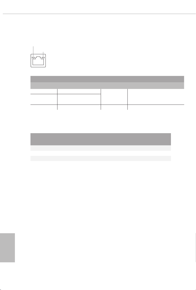
* ere are two LEDs on each LAN port. Please refer to the table below for the LAN port LED indications.
ACT/LINK L ED
SPEED LE D
LAN Por t
Activity / Link LED Speed LED
Status Description Status Description
O No Link O 10Mbps connection
Blinking Data Activity Orange 100Mbps connection
On Link Green 1Gbps connection
12
11
9 81015
7
English
3
** ere are two LEDs on each LAN port. Please refer to the table below for the LAN port LED indications.
ACT/LINK L ED
SPEED LE D
LAN Por t
Activity / Link LED Speed LED
Status Description Status Description
O No Link
Blinking Data Activity
Orange
10Mbps/100Mbps/1Gbps/2.5Gbps
/5Gbps connection
On Link Green 10Gbps connection
*** If you use a 2-channel speaker, please connect the speaker’s plug into “Front Speaker Jack”. See the table below
for connection d etails in accordance w ith the type of speaker you use.
English
4
Audio Output
Channels
Front Speaker
(No. 6)
Rear Speaker
(No. 4)
Central / Bass
(No. 3)
Line In
(No. 5)
2 V -- -- --
4 V V -- --
6 V V V --
8 V V V V
**** Please choose regular mini DisplayPort to DisplayPort adapter cables instead of right angled ones if you use
two mini DisplayPort input ports simultaneously.
***** ACPI wake-up function is not supported on USB3_ 34 ports.

WiFi-802.11ax Module and ASRock WiFi 2.4/5 GHz
Antenna
WiFi-802.11ax + BT Module
is motherboard comes with an exclusive WiFi 802.11 a/b/g/n/ax + BT v5.0
module (pre-installed on the rear I/O panel) that oers support for WiFi 802.11 a/b/
g/n/ax connectivity standards and Bluetooth v5.0. WiFi + BT module is an easy-touse wireless local area network (WLAN) adapter to support WiFi + BT. Bluetooth
v5.0 standard features Smart Ready technology that adds a whole new class of
functionality into the mobile devices. BT 5.0 also includes Low Energy Technology
and ensures extraordinary low power consumption for PCs. e 2T2R WiFi
solution sets a WiFi high speed standard and oers max link rate up to 2.4Gbps.
* e transmission speed may vary according to the environment.
X299 Creator
ASRock WiFi 2.4/5 GHz Antenna
English
5
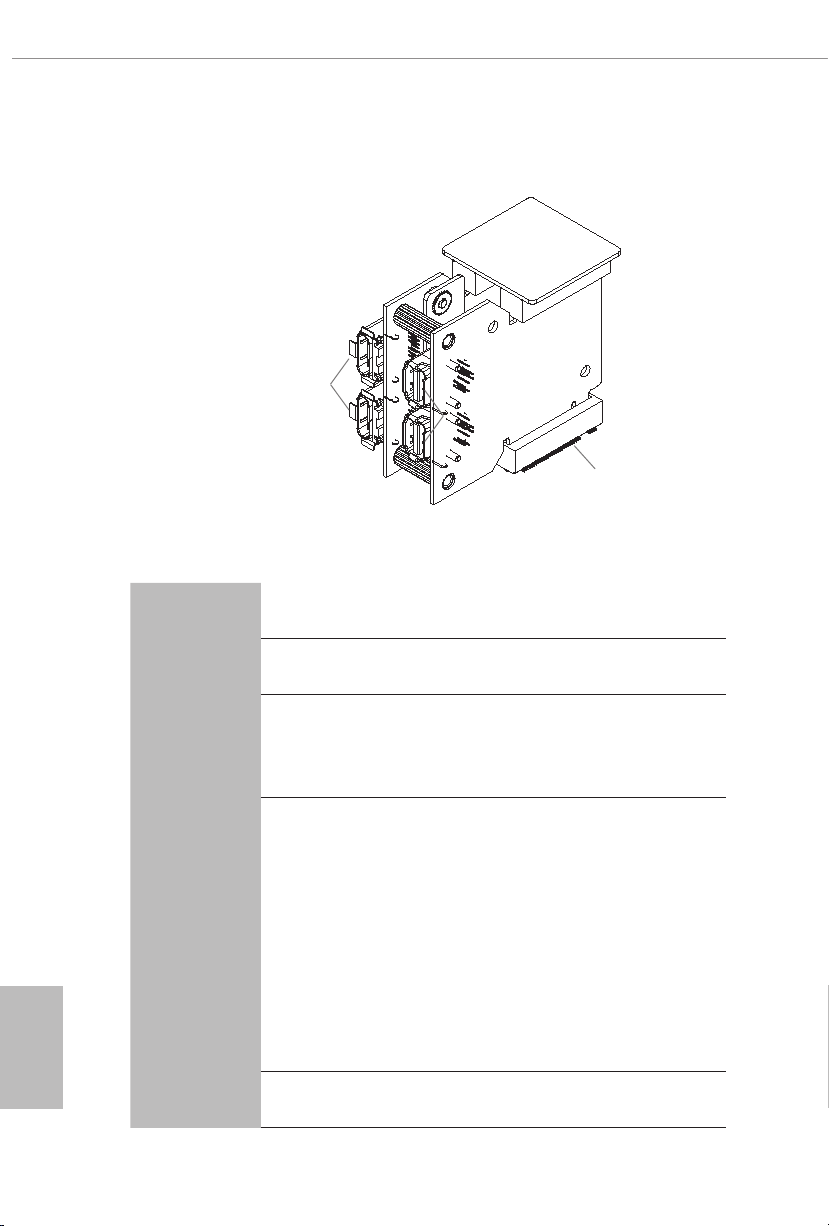
ASRock Thunderbolt™ 3 Module
USB 3.2 Gen2 underboltTM 3
Type-C Ports
Specications
Mini DisplayPort Input Ports
TBT_M2_1 and TBT_M2 _2
English
6
Platform
Controller
M.2
Connector
Interface
Size: 1.45-in x 1.65-in x 0.91-in, 3.7 cm x 4.2 cm x 2.3 cm
•
Intel® JHL7540 underboltTM 3 Controller (Titan Ridge)
•
Proprietary design for ASRock specic motherboard
•
* Please note that plugging into other M.2 connector may
damage the motherboard and this module
2 x NGFF M Key Type M.2 Connectors
•
2 x Mini DisplayPort 1.4 Input Ports
•
2 x USB 3.2 Gen2 underboltTM 3 Type-C Ports (40Gb/s for
•
underbolt protocol; 10 Gb/s for USB3.2 protocol) (Support
ESD Protection)*
*Supports daisy-chaining of up to six underboltTM devices.
*is port supports USB-PD 3.0 power outputs 9V/3A 27W and 5V/3A
15W. For charging Type-C USB devices, the device should support
Type-C standards to adjust the current because it will be dierent in
Power On state (3 Amp).
*Some Type-C USB devices may only be charged by its own adapter.
PCI Express 3.0 x4 interface
•

Graphics
Data Rate
OS
Supports underboltTM 3 interface with max. resolution of
•
5K (5120 x 2880) @ 60Hz for one display over a single cable
connection
Supports underboltTM 3 interface with max. resolution of
•
4K x 2K (4096x2160) @ 60Hz for dual displays over a single
cable connection
Supports up to two streams (eight lanes) of DisplayPort video
•
bandwidth; supports daisy-chaining of multiple DisplayPort
monitors
Supports 40Gbps bi-directional bandwidth per channel with
•
underboltTM 3 port
Microso® Windows® 10 64-bit
•
X299 Creator
English
7
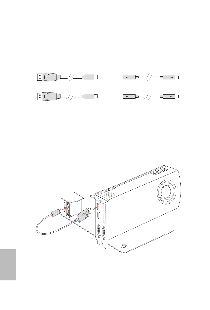
Installation
Step 1
Prepare two Mini DisplayPort to DisplayPort Adapter Cables and one/two
underboltTM cables. All these cables are not included in the package.
Step 2
Connect one end of the Mini DisplayPort to DisplayPort Adapter Cable to the Mini
DisplayPort Input Port (A) on ASRock underboltTM 3 Module on I/O panel.
en connect the other end of the cable to the DisplayPort Output Port (B) on the
graphics card.
English
8
A
B
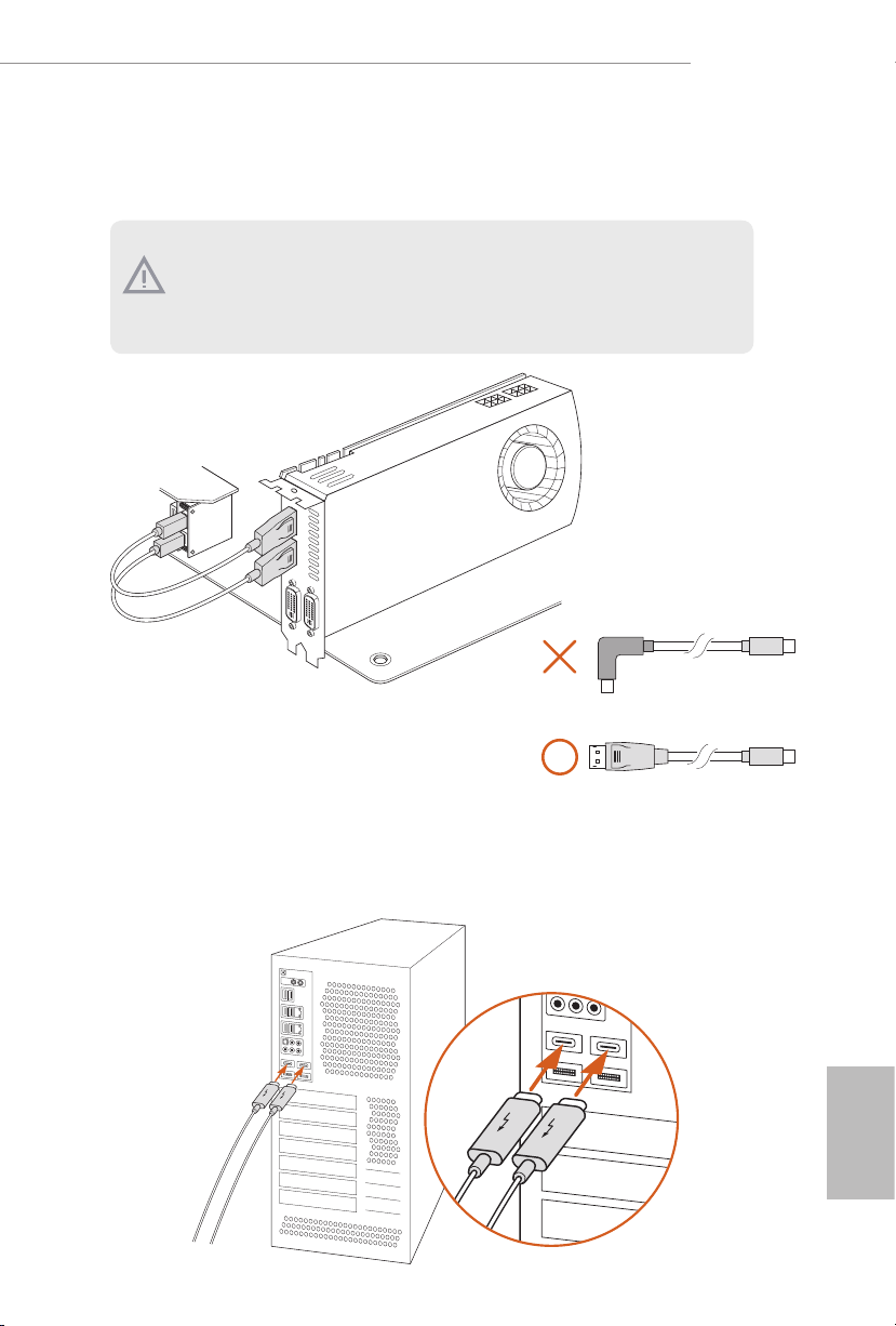
Step 3
Follow step 2 to connect the other Mini DisplayPort Input Port to the graphics card.
1. Make sure to connect both Mini DisplayPort Input Ports if you install the underboltTM output display device.
2. Please choose regular Mini DisplayPor t to DisplayPort Adapter Cable s instead of
right angled ones if you u se two Mini DisplayPort Input Ports simultaneously.
X299 Creator
Step 4
Connect the underboltTM cable(s) from your underbolt-enabled device(s) to the
USB 3.2 Gen2 underboltTM 3 Type-C Port(s) on ASRock underboltTM 3 Module
on I/O panel.
English
9

Chapter 1 Introduction
ank you for purchasing ASRock X299 Creator motherboard, a reliable
motherboard produced under ASRock’s consistently stringent quality control.
It delivers excellent performance with robust design conforming to ASRock’s
commitment to quality and endurance.
Becau se the motherboard specications and the BIOS soware might be updated, the
content of this documentation will be subject to change without notice. In case any
modications of this documentation occur, the updated version will be available on
ASRock’s website without further notice. If you require technical support related to
this motherboard, please vi sit our website for s pecic information about the model
you are using. You may nd the l atest VGA cards and CPU suppor t list on ASRock’s
website a s well. ASRock website http://www.a srock.com.
1.1 Package Contents
ASRock X299 Creator Motherboard (ATX Form Factor)
•
ASRock X299 Creator Quick Installation Guide
•
ASRock X299 Creator Support CD
•
1 x ASRock SLI_HB_Bridge_2S Card (Optional)
•
1 x ASRock WiFi 2.4/5 GHz Antenna (Optional)
•
4 x Serial ATA (SATA) Data Cables (Optional)
•
3 x Screws for M.2 Sockets (Optional)
•
3 x Standos for M.2 Sockets (Optional)
•
1 x I/O Panel Shield
•
English
10

1.2 Specications
Platform
CPU
Chipset
Memory
•
•
•
•
•
•
•
•
•
•
•
* e maximum memory frequency supported may vary by
processor type.
* Please refer to Memory Support List on ASRock’s website for
more information. (http://www.asrock.com/)
•
•
•
X299 Creator
ATX Form Factor
8 Layer PCB
2oz Copper PCB
Supports Intel® CoreTM X-Series Processor Family for the
LGA 2066 Socket (Cascade Lake-X, Skylake X Refresh and
Skylake X)
Digi Power design
13 Power Phase design
Supports Intel® Turbo Boost Max Technology 3.0
Intel® X299
Quad Channel DDR4 Memory Technology
8 x DDR4 DIMM Slots
Supports DDR4 4200+(OC)*/4000(OC)/3800(OC)/
3733(OC)/3600(OC)/3200(OC)/2933(OC)/2800
(OC)/2666/2400/2133 non-ECC, un-buered memory
Max. capacity of system memory: 256GB
Supports Intel® Extreme Memory Prole (XMP) 2.0
15μ Gold Contact in DIMM Slots
Expansion
Slot
4 x PCI Express 3.0 x16 Slots*
•
* If you install CPU with 48 lanes, PCIE1/PCIE2/PCIE3/PCIE5
will run at x16/x8/x16/x8.
If a M.2 PCI Express module is installed on M2_1 or M2_2,
PCIE2 will downgrade to x4 mode.
If M.2 PCI Express modules are installed on M2_1 and M2_2,
PCIE2 will be disabled.
* If you install CPU with 44 lanes, PCIE1/PCIE2/PCIE3/PCIE5
will run at x16/x4/x16/x8.
If a M.2 PCI Express module is installed on M2_1, PCIE2 will
be disabled.
English
11

Thunder-
TM
bolt
* If you install CPU with 28 lanes, PCIE1/PCIE2/PCIE3/PCIE5
will run at x16/x4/x8/x0.
If a M.2 PCI Express module is installed on M2_1, PCIE2 will
be disabled.
* Supports NVMe SSD as boot disks
1 x PCI Express 3.0 x1 Slot
•
Supports AMD 3-Way CrossFireXTM and CrossFireXTM **
•
Supports NVIDIA® 3-Way SLITM and SLITM**
•
Supports NVIDIA® NVLinkTM with dual NVIDIA® GeForce®
•
RTX series graphics cards***
Support NVIDIA® SLITM with NVIDIA® Quadro graphics
•
cards
** 3-Way CrossFireXTM and 3-Way SLITM are only supported
with CPU with 48 lanes or 44 lanes.
*** NVIDIA NVLink Bridge does not come with the package.
Please purchase it from NVIDIA® if necessary.
1 x Vertical M.2 Socket (Key E) with the bundled WiFi-
•
802.11ax module (on the rear I/O)
15μ Gold Contact in VGA PCIe Slot (PCIE1 and PCIE3)
•
Intel® JHL7540 underboltTM 3 Controller (Titan Ridge)
•
Supports underboltTM 3 interface with max. resolution of
•
5K (5120 x 2880) @ 60Hz for one display over a single cable
connection
Supports underboltTM 3 interface with max. resolution of
•
4K x 2K (4096x2160) @ 60Hz for dual displays over a single
cable connection
Supports up to two streams (eight lanes) of DisplayPort video
•
bandwidth; supports daisy-chaining of multiple DisplayPort
monitors
English
12
Audio
7.1 CH HD Audio with Content Protection (Realtek
•
ALC1220 Audio Codec)
Premium Blu-ray Audio support
•
Supports Surge Protection (ASRock Full Spike Protection)
•
Supports Purity SoundTM 4
•
- Nichicon Fine Gold Series Audio Caps
- 120dB SNR DAC with Dierential Amplier
- NE5532 Premium Headset Amplier for Front Panel
Audio Connector (Supports up to 600 Ohm headsets)
- Pure Power-In

- Direct Drive Technology
- PCB Isolate Shielding
- Impedance Sensing on Front Out port
-
Individual PCB Layers for R/L Audio Channel
- Gold Audio Jacks
- 15μ Gold Audio Connector
Supports DTS Connect
•
X299 Creator
LAN
Wireless
LAN
Rear Panel
I/O
1 x 10 Gigabit LAN 100/1000/2500/5000/10000 Mb/s
(AQUANTIA® AQC107):
Supports Lightning/ESD Protection
•
Supports PXE
•
1 x Intel Gigabit LAN 10/100/1000 Mb/s (Intel® I219V):
Supports Wake-On-LAN
•
Supports Lightning/ESD Protection
•
Supports Energy Ecient Ethernet 802.3az
•
Supports PXE
•
Intel® 802.11ax WiFi Module
•
Supports IEEE 802.11a/b/g/n/ax
•
Supports Dual-Band (2.4/5 GHz)
•
Supports high speed wireless connections up to 2.4Gbps
•
2 antennas to support 2 (Transmit) x 2 (Receive) diversity
•
technology
Supports Bluetooth 5.0 + High speed class II
•
Supports MU-MIMO
•
2 x Antenna Ports
•
1 x Optical SPDIF Out Port
•
2 x USB 2.0 Ports (Supports ESD Protection)
•
2 x USB 3.2 Gen2 underboltTM 3 Type-C Ports (40Gb/s for
•
underbolt protocol; 10 Gb/s for USB3.2 protocol) (Supports
ESD Protection)*
* Supports USB-PD 3.0 9V/3A(27W) and 5V/3A(15W)
2 x Mini DisplayPort Input Ports**
•
** Please choose regular mini DisplayPort to DisplayPort
adapter cables instead of right angled ones if you use two mini
DisplayPort input ports simultaneously.
4 x USB 3.2 Gen1 Ports (Supports ESD Protection)***
•
English
13

Storage
*** Ultra USB Power is supported on USB3_34 ports.
*** ACPI wake-up function is not supported on USB3_34 ports.
2 x RJ-45 LAN Ports with LED (ACT/LINK LED and SPEED
•
LED)
1 x Clear CMOS Button
•
HD Audio Jacks: Rear Speaker / Central / Bass / Line in /
•
Front Speaker / Microphone (Gold Audio Jacks)
8 x SATA3 6.0 Gb/s Connectors, support RAID (RAID 0,
•
RAID 1, RAID 5, RAID 10, Intel Rapid Storage Technology
17 and Intel Smart Response Technology), NCQ, AHCI and
Hot Plug*
* If M2_3 is occupied by a SATA-type M.2 device, SATA3_7
will be disabled.
2 x SATA3 6.0 Gb/s Connectors by ASMedia ASM1061, sup-
•
port NCQ, AHCI and Hot Plug
2 x Ultra M.2 Sockets (M2_1 and M2_2), support M Key
•
type 2242/2260/2280 M.2 PCI Express module up to Gen3
x4 (32 Gb/s)**
1 x Ultra M.2 Socket (M2_3), supports M Key type
•
2242/2260/2280/22110 M.2 SATA3 6.0 Gb/s module and M.2
PCI Express module up to Gen3 x4 (32 Gb/s)**
** If you install CPU with 44 or 28 lanes, M2_2 will be disabled.
** Supports Intel® OptaneTM Technology
** Supports PCIe RAID
** Supports NVMe SSD as boot disks
English
14
Connector
1 x Virtual RAID On CPU Header
•
1 x SPI TPM Header
•
1 x Power LED and Speaker Header
•
2 x RGB LED Headers
•
* Supports in total up to 12V/3A, 36W LED Strip
2 x Addressable LED Headers
•
* Support in total up to 5V/3A, 15W LED Strip
1 x CPU Fan Connector (4-pin)
•
* e CPU Fan Connector supports the CPU fan of maximum
1A (12W) fan power.
1 x CPU/Water Pump Fan Connector (4-pin) (Smart Fan
•
Speed Control)
* e CPU/Water Pump Fan supports the water cooler fan of
maximum 2A (24W) fan power.

5 x Chassis/Water Pump Fan Connectors (4-pin) (Smart Fan
•
Speed Control)
* e Chassis/Water Pump Fan supports the water cooler fan of
maximum 2A (24W) fan power.
* CPU_FAN2/WP, CHA_FAN1~5/WP can auto detect if 3-pin
or 4-pin fan is in use.
1 x 24 pin ATX Power Connector (Hi-Density Power Con-
•
nector)
2 x 8 pin 12V Power Connectors (Hi-Density Power Connec-
•
tor)
1 x Front Panel Audio Connector (15μ Gold Audio Connec-
•
tor)
2 x USB 2.0 Headers (Support 4 USB 2.0 ports) (Supports
•
ESD Protection)
1 x USB 3.2 Gen1 Header (Supports 2 USB 3.2 Gen1 ports)
•
(Supports ESD Protection)
1 x Front Panel Type C USB 3.2 Gen2 Header (ASMedia
•
ASM3142)
1 x Dr. Debug with LED
•
1 x Power Button with LED
•
1 x Reset Button
•
X299 Creator
BIOS
Feature
Hardware
Monitor
2 x AMI UEFI Legal BIOS with multilingual GUI support (1
•
x Main BIOS and 1 x Backup BIOS)
Supports Secure Backup UEFI Technology
•
ACPI 6.1 Compliant wake up events
•
SMBIOS 3.0 Support
•
CPU, DRAM, VPPM, VTTM, PCH 1.0V, VCCMPHY, VC-
•
CIO, VCCSA, VCCPLL, CLK VDD Voltage Multi-adjust-
ment
Temperature Sensing: CPU, CPU/Water Pump, Chassis/Wa-
•
ter Pump Fans
Fan Tachometer: CPU, CPU/Water Pump, Chassis/Water
•
Pump Fans
Quiet Fan (Auto adjust chassis fan speed by CPU tempera-
•
ture): CPU, CPU/Water Pump, Chassis/Water Pump Fans
Fan Multi-Speed Control: CPU, CPU/Water Pump, Chassis/
•
Water Pump Fans
Voltage monitoring: +12V, +5V, +3.3V, CPU Vcore, DRAM,
•
PCH 1.0V, VCCIO, VCCSA
English
15

Microso® Windows® 10 64-bit
OS
Certications
* For detailed product information, please visit our website: http://ww w.asrock.com
Please realize that the re is a certain risk involved with overclocking, including
adjusting the setting in the BIOS, applying Untied Overclocking Technology, or using
third-party overclocking tool s. Overclocking may aect your system’s stability, or
even cause damage to the components and devices of your system. It should be done
at your own risk and expense. We are not responsible for possible damage caused by
overclocking.
•
FCC, CE
•
ErP/EuP ready (ErP/EuP ready power supply is required)
•
English
16

Chapter 2 Installation
is is an ATX form factor motherboard. Before you install the motherboard, study
the conguration of your chassis to ensure that the motherboard ts into it.
Pre-installation Precautions
Take note of the following precautions before you install motherboard components
or change any motherboard settings.
Make sure to unplug the power cord before installing or removing the motherboard
•
components. Failure to do so may cause physical injuries and damages to motherboard
components.
In order to avoid damage from static electricity to the motherboard’s components,
•
NEVER place your motherboard directly on a carpet. Also remember to use a grounded
wrist strap or touch a safety grounded object before you handle the components.
Hold components by the edges and do not touch the ICs.
•
Whenever you uninstall any components, place them on a grounded anti-static pad or
•
in the bag that comes with the components.
When placing screws to secure the motherboard to the chassis, please do not over-
•
tighten the screws! Doing so may damage the motherboard.
X299 Creator
17
English

2.1 Installing the CPU
1. Before you insert the 2066 -Pin CPU into the socket, please check if the P nP cap
is on the socket, if the CPU sur face is unclean, or if there are any b ent pins in the
socket. Do not force to insert the CPU into the socket if above situation is found.
Other wise, the CPU will be seriously d amaged.
2. Unplug all power cables be fore installing the CPU.
CAUTION:
Please note that X299 platform is only compatible with the LGA 2066 socket, which is
incompatible with the LGA 2011-3 socket (for X99 platform).
1
A
B
English
18
A
2
B

X299 Creator
3
4
A
B
5
English
19

6
A
B
7
A
B
English
20
8
Please save and replace the cover if the processor i s removed. e cover must be
placed if you wish to return the motherboard for aer service.

2.2 Installing the CPU Fan and Heatsink
1 2
X299 Creator
FAN
CPU_
English
21

2.3 Installation of Memory Modules (DIMM)
is motherboard provides eight 288-pin DDR4 (Double Data Rate 4) DIMM slots, and
supports Quad Channel Memory Technology.
1. For quad channel conguration, you always need to install identical (the same
brand, speed , size and chip-type) DDR4 DIMM pairs.
2. It is not allowed to install a DDR, DDR2 or DDR3 memory module into a DDR4
slot; otherwise, this motherboard and DIMM may be damaged.
3. e DIMM only ts in one correct orientation. It will cause permanent damage to
the mothe rboard and the DIMM if you force the DIMM into the slot at incor rect
orientation.
Quad Channel Memory Conguration (For CPU with 48, 44 or 28 PCIe
lanes)
Priority 1 2
DDR4_B1
DDR4_B2
DDR4_ A1
DDR4_ A2
DDR4_D1
DDR4_D2
DDR4_C1
DDR4_C2
Populated Populated
Populated
Populated Populated
Populated
Populated Populated
Populated
Populated Populated
Populated
English
22
Due to Intel® CPU spec denition, please install the memory modules on DDR4_A1,
•
DDR4_B1, DDR4_C1 and DDR4_D1 for rst priority. If the four DDR4 DIMM slots
above are fully installed, and you want to use more than four memory modules, please
install the other memory modules from le to right (from DDR4_A2, DDR4_B2,
DDR4_D2 to DDR4_C2.)
If only two memory modules are installed in the DDR4 DIMM slots, then Dual
•
Channel Memory Technology is activated. If three memory modules are installed, then
Triple Channel Memory Technology is activated. If more than four memory modules
are installed in the DDR4 DIMM slots, then Quad Channel Memory Technology is
activated.

X299 Creator
1
2
3
English
23

2.4 Expansion Slots (PCI Express Slots)
ere are 5 PCI Express slots on the motherboard.
Before installing an ex pansion card, please make sure that the power supply is
switched o or the power cord is unplugged. Plea se read the documentation of the
expan sion card and make necessary hardware settings for the card before you start
the installation.
PCIe slots:
PCIE1 (PCIe 3.0 x16 slot) is used for PCI Express x16 lane width graphics cards.
PCIE2 (PCIe 3.0 x16 slot) is used for PCI Express x8 lane width graphics cards.
PCIE3 (PCIe 3.0 x16 slot) is used for PCI Express x16 lane width graphics cards.
PCIE4 (PCIe 3.0 x1 slot) is used for PCI Express x1 lane width cards.
PCIE5 (PCIe 3.0 x16 slot) is used for PCI Express x8 lane width graphics cards.
*If you install CPU with 48 lanes, PCIE1/PCIE2/PCIE3/PCIE5 will run at x16/x8/
x16/x8.
* If you install CPU with 44 lanes, PCIE1/PCIE2/PCIE3/PCIE5 will run at x16/x4/
x16/x8.
* If you install CPU with 28 lanes, PCIE1/PCIE2/PCIE3/PCIE5 will run at x16/x4/
x8/x0.
PCIe Slot Congurations (For CPU with 48 PCIe lanes)
PCIE1 PCIE2 PCIE3 PCIE4 PCIE5
English
24
Single Graphics Card x16 N/A N/A N/A N/A
Two Graphics Cards in
CrossFireXTM or SLITM
x16 N/A x16 N/A N/A
Mode
ree Graphics Cards in
3-Way CrossFireXTM Mode
or 3-Way SLI
TM
Mode
x16 N/A x16 N/A x8
If a M.2 PCI Express module is installed on M2_1 or M2_2, PCIE2 will downgrade to x4 mode.
If M.2 PCI Express modules are installed on M2_1 and M2_2, PCIE2 will be disabled.

PCIe Slot Congurations (For CPU with 44 PCIe lanes)
PCIE1 PCIE2 PCIE3 PCIE4 PCIE5
Single Graphics Card x16 N/A N/A N/A N/A
Two Graphics Cards in
CrossFireXTM or SLITM
Mode
ree Graphics Cards in
3-Way CrossFireXTM Mode
or 3-Way SLITM Mode
If a M.2 PCI Express module is installed on M2_1, PCIE2 will be disabled.
x16 N/A x16 N/A N/A
x16 N/A x16 N/A x8
PCIe Slot Congurations (For CPU with 28 PCIe lanes)
PCIE1 PCIE2 PCIE3 PCIE4 PCIE5
Single Graphics Card x16 N/A N/A N/A N/A
X299 Creator
Two Graphics Cards in
CrossFireXTM or SLITM
Mode
If a M.2 PCI Express module is installed on M2_1, PCIE2 will be disabled.
For a better ther mal environment, please connect a chassi s fan to the motherboard’s
chassis fan connector (CHA_ FAN1/WP, CHA_ FAN2/WP, CHA_FAN3/WP, CHA_
FAN4/WP or CHA_ FA N5/WP) when using multiple g raphics cards.
* If you install CPU with 44 or 28 lanes and encounter CrossFire issues, please
do the followings.
1. Enter UEFI by pressing <F2> or <Del> during system startup.
2. Select “Boot > CSM” from the menu.
3. Set "Launch Storage OpROM policy" to "UEFI only".
4. Press F10 to Save and Exit.
x16 N/A x8 N/A N/A
English
25

PCIE Slot Speed (For CPU with 48 PCIe lanes)
PCIE1 x16
PCIE2 x8
PCIE3 x16
PCIE4 x1 (PCH)
PCIE5 x8
*If M.2 PCI Express modules are installed on M2_1 and M2_2, PCIE2 will be disabled.
PCIE Slot Speed (For CPU with 44 PCIe lanes)
PCIE1 x16
English
26
PCIE2
PCIE3 x16
PCIE4 x1 (PCH)
PCIE5 x8
*If a M.2 PCI Express module is installed on M2_1, PCIE2 will be disabled.
x4
PCIE Slot Speed (For CPU with 28 PCIe lanes)
PCIE1 x16
PCIE2 x4
PCIE3 x8
PCIE4 x1 (PCH)
PCIE5 N/A
*If a M.2 PCI Express module is installed on M2_1, PCIE2 will be disabled.
 Loading...