

Page 1
Copyright Notice:
No part of this installation guide may be reproduced, transcribed, transmitted, or translated in any language, in any form or by any means, except duplication of documentation
by the purchaser for backup purpose, without written consent of ASRock Inc.
Products and corporate names appearing in this guide may or may not be registered
trademarks or copyrights of their respective companies, and are used only for identifi ca-
tion or explanation and to the owners’ benefi t, without intent to infringe.
Disclaimer:
Specifi cations and information contained in this guide are furnished for informational use
only and subject to change without notice, and should not be constructed as a commitment by ASRock. ASRock assumes no responsibility for any errors or omissions that may
appear in this guide.
With respect to the contents of this guide, ASRock does not provide warranty of any kind,
either expressed or implied, including but not limited to the implied warranties or conditions of merchantability or fi tness for a particular purpose. In no event shall ASRock, its
directors, offi cers, employees, or agents be liable for any indirect, special, incidental, or
consequential damages (including damages for loss of profi ts, loss of business, loss of
data, interruption of business and the like), even if ASRock has been advised of the possibility of such damages arising from any defect or error in the guide or product.
This device complies with Part 15 of the FCC Rules. Operation is subject to the following
two conditions:
(1) this device may not cause harmful interference, and
(2) this device must accept any interference received, including interference that
may cause undesired operation.
CALIFORNIA, USA ONLY
The Lithium battery adopted on this motherboard contains Perchlorate, a toxic substance
controlled in Perchlorate Best Management Practices (BMP) regulations passed by the
California Legislature. When you discard the Lithium battery in California, USA, please
follow the related regulations in advance.
“Perchlorate Material-special handling may apply, see
www.dtsc.ca.gov/hazardouswaste/perchlorate”
ASRock Website: http://www.asrock.com
Published August 2012
Copyright©2012 ASRock INC. All rights reserved.
ASRock P75 Pro3 Motherboard
English
1
Page 2
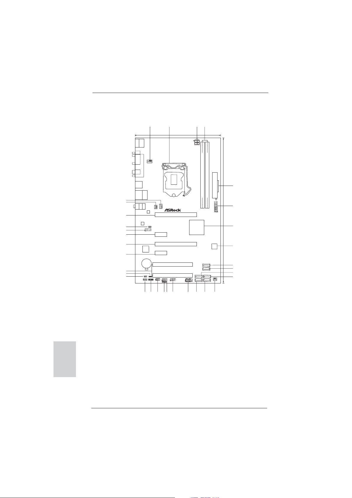
Motherboard Layout
1
2
4
3
17.8cm (7.0in)
USB2.0
T: US B0
B:USB1
Keyboard
Mouse/
PS2
COM1
PARALLEL PORT
CPU_FAN1
Coaxial
SPDIF
USB3.0
T: US B0
B:USB1
USB2.0
Top:
T: US B2
RJ-45
B:USB3
33
32
31
30
29
28
27
26
25
24
23
Top:
LINE IN
Bottom:
MIC IN
Center:
FRONT
AUDIO
CODEC
Super
1
1
CLRCMOS1
22
1
I/O
CMOS
Battery
CI1
HD_AUDIO1
LAN
PHY
HDMI_SPDIF1
1
1
SPEAKER1
1
CHA_FAN1
PWR_FAN1
PCIE1
ErP/EuPReady
Front USB3.0
PCIE2
PCI Express3.0
PCIE3
X
PCIE4
X
X
Fast LAN
PCI1
PLED1
21
PCI2
USB4_5
USB6_7
1
1
1
IR1
1
CIR1
20
18
19
17
Fast USB
Fast RAM
PANEL1
P75 Pro3
Intel
B75
PLEDPWRBTN
1
HDLED RESET
16
ATX12V1
15
RoHS
SATA2_2
SATA2_1
DDR3
DDR3_A1 (64bit, 240-pin module)
SATA3_0
SATA2_5
SATA2_4
SATA2_3
14
DDR3_B1 (64bit, 240-pin module)
USB3_2_3
64Mb
BIOS
CHA_FAN2
13
ATXPWR1
1
30.5cm (12.0in)
5
6
7
8
9
10
11
12
English
2
1 CPU Fan Connector (CPU_FAN1)
2 1155-Pin CPU Socket
3 ATX 12V Power Connector (ATX12V1)
4 2 x 240-pin DDR3 DIMM Slots
(DDR3_A1, DDR3_B1, Black)
5 ATX Power Connector (ATXPWR1)
6 USB 3.0 Header (USB3_2_3, Black)
7 Intel B75 Chipset
8 SPI Flash Memory (64Mb)
9 SATA3 Connector (SATA3_0, Gray)
10 SATA2 Connector (SATA2_5, Black)
11 SATA2 Connector (SATA2_2, Black)
12 SATA2 Connector (SATA2_4, Black)
13 Chassis Fan Connector (CHA_FAN2)
14 SATA2 Connector (SATA2_3, Black)
15 SATA2 Connector (SATA2_1, Black)
16 System Panel Header (PANEL1, Black)
17 USB 2.0 Header (USB6_7, Black)
ASRock P75 Pro3 Motherboard
18 USB 2.0 Header (USB4_5, Black)
19 Consumer Infrared Module Header
(CIR1, Gray)
20 Infrared Module Header (IR1, Black)
21 Chassis Speaker Header (SPEAKER1, Black)
22 Clear CMOS Jumper (CLRCMOS1)
23 Chassis Intrusion Header (CI1)
24 Power LED Header (PLED1)
25 PCI Slots (PCI1-2, Black)
26 PCI Express 2.0 x1 Slot (PCIE4, Black)
27 PCI Express 2.0 x16 Slot (PCIE3, Black)
28 PCI Express 2.0 x1 Slot (PCIE2, Black)
29 Front Panel Audio Header (HD_AUDIO1, Black)
30 HDMI_SPDIF Header (HDMI_SPDIF1, Black)
31 PCI Express 3.0 x16 Slot (PCIE1, Black)
32 Power Fan Connector (PWR_FAN1)
33 Chassis Fan Connector (CHA_FAN1)
Page 3
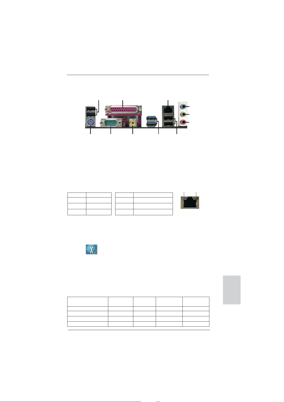
I/O Panel
1
2
3
4
5
6
11
1 USB 2.0 Ports (USB01)
2 Parallel Port
* 3 LAN RJ-45 Port
4 Line In (Light Blue)
** 5 Front Speaker (Lime)
6 Microphone (Pink)
10
9
7 USB 2.0 Ports (USB23)
8 USB 3.0 Ports (USB3_0_1)
9 Coaxial SPDIF Out Port
10 COM Port
11 PS/2 Mouse/Keyboard Port (Purple)
8
7
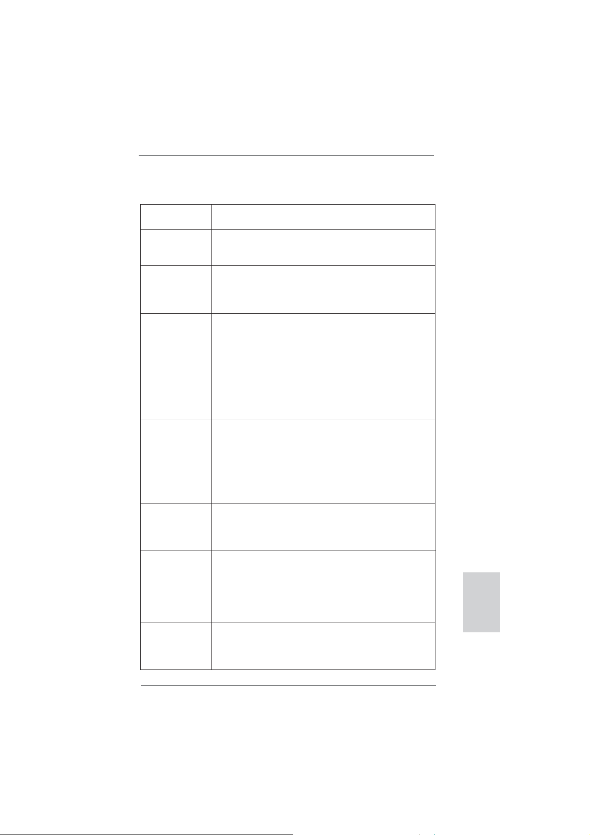
* There is one LED next to the LAN port. Please refer to the table below for the LAN port LED
indications.
Activity/Link LED SPEED LED
LAN Port LED Indications
ACT/LINK
LED
SPEED
LED
Status Description Status Description
Off No Link Off 10Mbps connection
Blinking Data Activity Orange 100Mbps connection
On Link Green 1Gbps connection
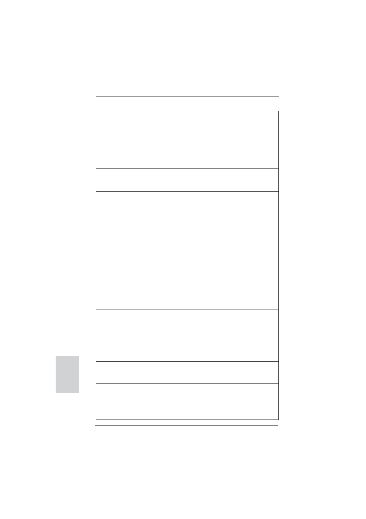
** If you enable Multi-Streaming function, this motherboard can support up to 5.1 CH audio only.
To enable Multi-Streaming function, you need to connect a front panel audio cable to the front
panel audio header. Please refer to below steps for the software setting of Multi-Streaming.
For Windows® XP:
After restarting your computer, you will fi nd “Mixer” tool on your system. Please select “Mixer
ToolBox” , click “Enable playback multi-streaming”, and click “ok”. Choose “2CH” or
“4CH” and then you are allowed to select “Realtek HDA Primary output” to use Rear Speaker
and Front Speaker, or select “Realtek HDA Audio 2nd output” to use front panel audio. Then
reboot your system.
For Windows
After restarting your computer, please double-click “Realtek HD Audio Manager” on the
system tray. Set “Speaker Confi guration” to “Quadraphonic” or “Stereo”. Click “Device
advanced settings”, choose “Make front and rear output devices playbacks two different audio
streams simultaneously”, and click “ok”. Then reboot your system.
Audio Output Channels Front Speaker Line In Microphone Front Panel
(No. 5) (No. 4) (No. 6) Headphone
®
7 / VistaTM:
2 V -- -- -4 V V -- -6 V V V -8 V V V V
LAN Port
ASRock P75 Pro3 Motherboard
English
3
Page 4
1. Introduction
Thank you for purchasing ASRock P75 Pro3 motherboard, a reliable motherboard
produced under ASRock’s consistently stringent quality control. It delivers excellent
performance with robust design conforming to ASRock’s commitment to quality and
endurance.
This Quick Installation Guide contains introduction of the motherboard and step-bystep installation guide. More detailed information of the motherboard can be found
in the user manual presented in the Support CD.
Because the motherboard specifi cations and the BIOS software might be
updated, the content of this manual will be subject to change without notice. In case any modifi cations of this manual occur, the updated version
will be available on ASRock website without further notice. You may fi nd
the latest VGA cards and CPU support lists on ASRock website as well.
ASRock website http://www.asrock.com
If you require technical support related to this motherboard, please visit
our website for specifi c information about the model you are using.
www.asrock.com/support/index.asp
1.1 Package Contents
ASRock P75 Pro3 Motherboard
(ATX Form Factor: 12.0-in x 7.0-in, 30.5 cm x 17.8 cm)
ASRock P75 Pro3 Quick Installation Guide
ASRock P75 Pro3 Support CD
2 x Serial ATA (SATA) Data Cables (Optional)
1 x I/O Panel Shield
English
4
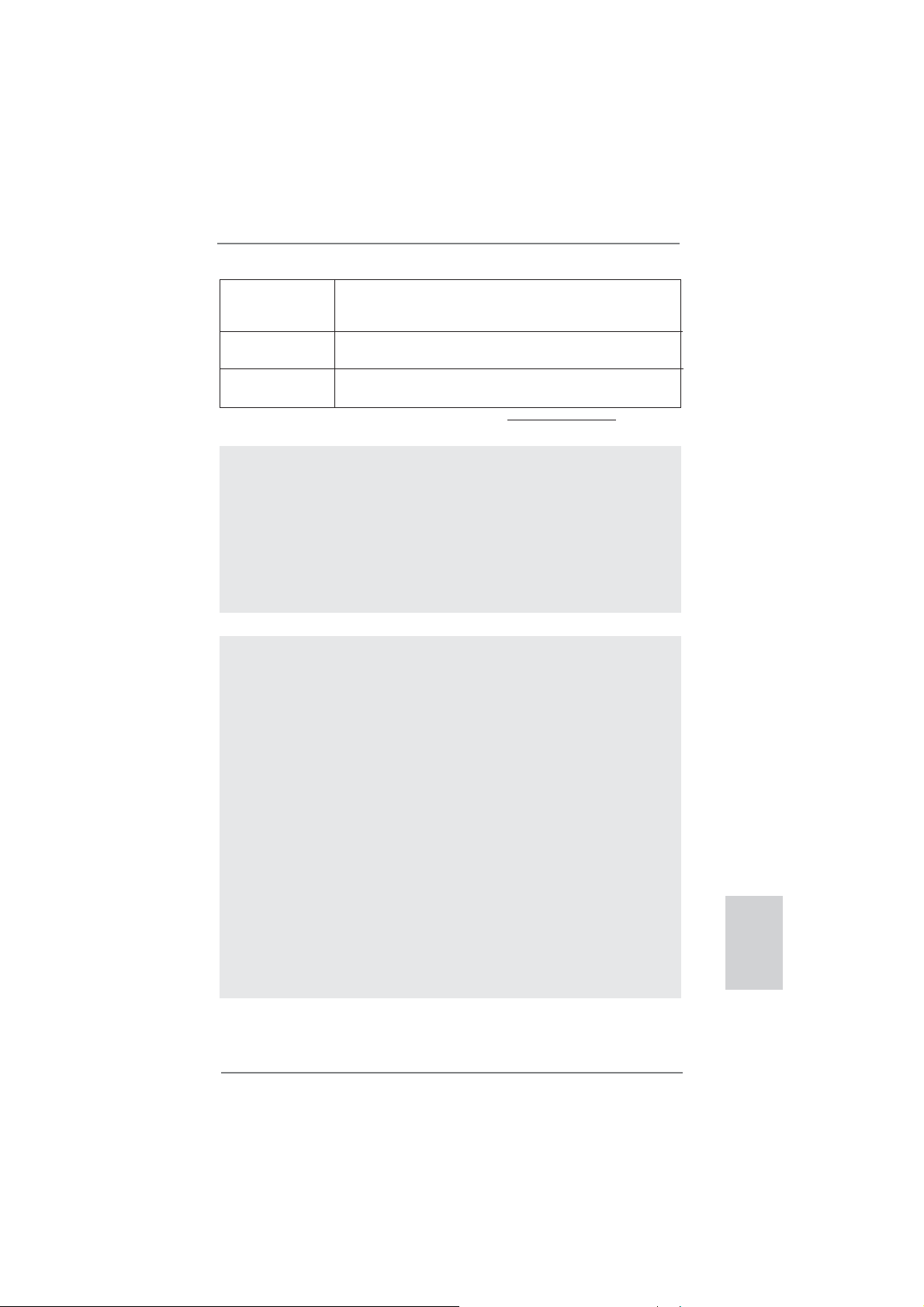
ASRock Reminds You...
To get better performance in Windows® 7 / 7 64-bit / Vista
bit, it is recommended to set the BIOS option in Storage Confi guration to
AHCI mode. For the BIOS setup, please refer to the “User Manual” in our
support CD for details.
TM
/ VistaTM 64-
ASRock P75 Pro3 Motherboard
Page 5
1.2 Specifi cations
Platform - ATX Form Factor: 12.0-in x 7.0-in, 30.5 cm x 17.8 cm
- All Solid Capacitor design
CPU - Supports 3
LGA1155 Package
- Supports Intel
Chipset - Intel® B75
- Supports Intel® Small Business Advantage (see CAUTION 1)
- Supports Intel® Rapid Start Technology and Smart Connect
Technology
Memory - Dual Channel DDR3 Memory Technology
- 2 x DDR3 DIMM slots
- Supports DDR3 2200(OC)*/1600/1333/1066 non-ECC,
un-buffered memory (DDR3 1600 with Intel
CPU, DDR3 1333 with Intel® Sandy Bridge CPU)
* DDR3 2200(OC) is only supported with Intel® CoreTM i7
3770K
- Max. capacity of system memory: 16GB (see CAUTION 2)
- Supports Intel
Expansion Slot - 1 x PCI Express 3.0 x16 slot (PCIE1: x16 mode)
* PCIE 3.0 is only supported with Intel
Intel® Sandy Bridge CPU, it only supports PCIE 2.0.
- 1 x PCI Express 2.0 x16 slot (PCIE3: x4 mode)
- 2 x PCI Express 2.0 x1 slots
- 2 x PCI slots
- Supports AMD Quad CrossFireXTM and CrossFireX
Audio - 7.1 CH HD Audio (Realtek ALC887 Audio Codec)
* To confi gure 7.1 CH audio, please use an HD front panel
audio module and enable the multi-channel audio feature
through the audio driver.
LAN - PCIE x1 Gigabit LAN 10/100/1000 Mb/s
- Realtek RTL8111E
- Supports Wake-On-LAN
- Supports LAN Cable Detection
- Supports Energy Effi cient Ethernet 802.3az
- Supports PXE
Rear Panel I/O I/O Panel
- 1 x PS/2 Mouse/Keyboard Port
- 1 x Parallel Port (ECP/EPP Support)
- 1 x Serial Port: COM1
rd
and 2nd Generation Intel® CoreTM i7 / i5 / i3 in
®
Turbo Boost 2.0 Technology
®
Ivy Bridge
®
Extreme Memory Profi le (XMP)1.3/1.2
®
Ivy Bridge CPU. With
TM
English
ASRock P75 Pro3 Motherboard
5
Page 6
English
6
- 1 x Coaxial SPDIF Out Port
- 4 x Ready-to-Use USB 2.0 Ports
- 2 x Ready-to-Use USB 3.0 Ports
- 1 x RJ-45 LAN Port with LED (ACT/LINK LED and SPEED
LED)
- HD Audio Jack: Line in/Front Speaker/Microphone
SATA 3 - 1 x SATA3 6.0 Gb/s connector, supports NCQ, AHCI and
Hot Plug functions
USB3.0
- 1 x Front USB 3.0 header (supports 2 USB 3.0 ports),
supports USB 1.1/2.0/3.0 up to 5Gb/s
Connector - 5 x SATA2 3.0 Gb/s connectors, support NCQ, AHCI and
Hot Plug functions
- 1 x IR header
- 1 x CIR header
- 1 x HDMI_SPDIF header
- 1 x Power LED header
- 1 x Chassis Intrusion header
- 1 x CPU Fan connector (4-pin)
- 2 x Chassis Fan connectors (1 x 4-pin, 1 x 3-pin)
- 1 x Power Fan connector (3-pin)
- 24 pin ATX power connector
- 4 pin 12V power connector
- Front panel audio connector
- 2 x USB 2.0 headers (support 4 USB 2.0 ports)
- 1 x USB 3.0 header (supports 2 USB 3.0 ports)
BIOS Feature - 64Mb AMI UEFI Legal BIOS with GUI support
- Supports “Plug and Play”
- ACPI 1.1 Compliance Wake Up Events
- Supports jumperfree
- SMBIOS 2.3.1 Support
- CPU Core, DRAM, 1.8V PLL, VTT, VCCSA Voltage
Multi-adjustment
Support CD - Drivers, Utilities, AntiVirus Software (Trial Version),
CyberLink MediaEspresso 6.5 Trial, ASRock MAGIX
Multimedia Suite - OEM
Hardware - CPU Temperature Sensing
Monitor - Chassis Temperature Sensing
- CPU/Chassis/Power Fan Tachometer
- CPU/Chassis Quiet Fan (Allows Chassis Fan Speed Auto Adjust by CPU Temperature)
- 2 x Rear USB 3.0 ports, support USB 1.1/2.0/3.0 up to 5Gb/s
- 1 x SATA3 6.0Gb/s connector
ASRock P75 Pro3 Motherboard
Page 7
- CPU/Chassis Fan Multi-Speed Control
- CASE OPEN detection
- Voltage Monitoring: +12V, +5V, +3.3V, CPU Vcore
OS - Microsoft® Windows® 7 / 7 64-bit / VistaTM / VistaTM 64-bit /
XP / XP 64-bit compliant (see CAUTION 3)
Certifi cations - FCC, CE, WHQL
- ErP/EuP Ready (ErP/EuP ready power supply is required)
* For detailed product information, please visit our website: http://www.asrock.com
WARNING
Please realize that there is a certain risk involved with overclocking,
including adjusting the setting in the BIOS, applying Untied Overclocking
Technology, or using third-party overclocking tools. Overclocking may
affect your system’s stability, or even cause damage to the components
and devices of your system. It should be done at your own risk and
expense. We are not responsible for possible damage caused by
overclocking.
CAUTION!
1. Intel® Small Business Advantage is a customizable platform integrated with IT tools, which helps maximize employee productivity, PC performance, and data security. There are applications
including Software Monitor, PC Health Center, Data Backup &
Restore, Energy Saver and USB Blocker.
2. Due to the operating system limitation, the actual memory size
may be less than 4GB for the reservation for system usage
under Windows
CPU, there is no such limita
RAM to utilize the memory that Windows® cannot use.
3. ASRock XFast RAM is not supported by Microsoft® Windows®
XP / XP 64-bit. Intel® Smart Connect Technology and Intel® USB
3.0 ports are not supported by Microsoft® Windows® VistaTM /
VistaTM 64-bit / XP / XP
64-bit.
®
7 / VistaTM / XP. For Windows® OS with 64-bit
tion. You can use ASRock XFast
English
ASRock P75 Pro3 Motherboard
7
Page 8

1.3 Unique Features
ASRock Extreme Tuning Utility (AXTU)
ASRock Extreme Tuning Utility (AXTU) is an all-in-one tool to
ne-tune different system functions in a user-friendly interface,
which includes Hardware Monitor, Fan Control, Overclocking,
OC DNA, IES and XFast RAM. In Hardware Monitor, it shows
the major readings of your system. In Fan Control, it shows the
fan speed and temperature for you to adjust. In Overclocking,
you are allowed to overclock CPU frequency for optimal system
performance. In OC DNA, you can save your OC settings as
a profi le and share it with your friends. Your friends then can
load the OC profi le to their own system to get the same OC set-
tings. In IES (Intelligent Energy Saver), the voltage regulator
can reduce the number of output phases to improve effi ciency
when the CPU cores are idle without sacrifi cing computing per-
formance. In
cannot be used under Windows
ASRock Instant Boot
ASRock Instant Boot allows you to turn on your PC in just a few
seconds, provides a much more effi cient way to save energy,
time, money, and improves system running speed for your system. It leverages the S3 and S4 ACPI features which normally
enable the Sleep/Standby and Hibernation modes in Windows
to shorten boot up time. By calling S3 and S4 at specifi c timing
during the shutdown and startup process, Instant Boot allows
you to enter your Windows
XFast RAM, it fully utilizes the memory space that
®
OS 32-bit CPU.
®
desktop in a few seconds.
®
English
8
ASRock Instant Flash
ASRock Instant Flash is a BIOS fl ash utility embedded in Flash
ROM. This convenient BIOS update tool allows you to update
system BIOS without entering operating systems fi rst like MS-
DOS or Windows
®
. With this utility, you can press the <F6> key
during the POST or the <F2> key to enter into the BIOS setup
menu to access ASRock Instant Flash. Just launch this tool and
save the new BIOS fi le to your USB fl ash drive, fl oppy disk or
hard drive, then you can update your BIOS only in a few clicks
without preparing an additional fl oppy diskette or other compli-
cated fl ash utility. Please be noted that the USB fl ash drive or
hard drive must use FAT32/16/12 fi le system.
ASRock P75 Pro3 Motherboard
Page 9

ASRock APP Charger
If you desire a faster, less restricted way of charging your
Apple devices, such as iPhone/iPad/iPod Touch, ASRock has
prepared a wonderful solution for you - ASRock APP Charger.
Simply install the APP Charger driver, it makes your iPhone
charge much quickly from your computer and up to 40% faster
than before. ASRock APP Charger allows you to quickly charge
many Apple devices simultaneously and even supports continuous charging when your PC enters into Standby mode (S1),
Suspend to RAM (S3), hibernation mode (S4) or power off (S5).
With APP Charger driver installed, you can easily enjoy the marvelous charging experience.
ASRock XFast USB
ASRock XFast USB can boost USB storage device perfor-
mance. The performance may depend on the properties of the
device.
ASRock XFast LAN
ASRock XFast LAN provides a faster internet access, which
includes the benefits listed below. LAN Application Prioritization: You can confi gure your application’s priority ideally and/or
add new programs. Lower Latency in Game: After setting online
game’s priority higher, it can lower the latency in games. Traffi c
Shaping: You can watch Youtube HD videos and download simultaneously. Real-Time Analysis of Your Data: With the status
window, you can easily recognize which data streams you are
transferring currently.
ASRock XFast RAM
ASRock XFast RAM is a new function that is included into ASRock Extreme Tuning Utility (AXTU). It fully utilizes the memory
space that cannot be used under Windows® OS 32-bit CPU.
ASRock XFast RAM shortens the loading time of previously
visited websites, making web surfing faster than ever. And it
also boosts the speed of Adobe Photoshop 5 times faster. Another advantage of ASRock XFast RAM is that it reduces the
frequency of accessing your SSDs or HDDs in order to extend
their lifespan.
ASRock P75 Pro3 Motherboard
English
9
Page 10

ASRock Crashless BIOS
ASRock Crashless BIOS allows users to update their BIOS
without fear of failing. If power loss occurs during the BIOS update process, ASRock Crashless BIOS will automatically fi nish
the BIOS update procedure after regaining power. Please note
that BIOS fi les need to be placed in the root directory of your
USB disk. Only USB2.0 ports support this feature.
ASRock On/Off Play Technology
ASRock On/Off Play Technology allows users to enjoy the great
audio experience from the portable audio devices, such like
MP3 player or mobile phone to your PC, even when the PC is
turned off (or in ACPI S5 mode)! This motherboard also provides
a free 3.5mm audio cable (optional) that ensures users the most
convenient computing environment.
ASRock OMG (Online Management Guard)
Administrators are able to establish an internet curfew or restrict
internet access at specifi ed times via OMG. You may schedule
the starting and ending hours of internet access granted to other
users. In order to prevent users from bypassing OMG, guest
accounts without permission to modify the system time are required.
ASRock Internet Flash
ASRock Internet Flash searches for available UEFI firmware
updates from our servers. In other words, the system can autodetect the latest UEFI from our servers and fl ash them without
entering Windows
®
OS. Please note that you must be running
on a DHCP confi gured computer in order to enable this function.
English
10
ASRock UEFI System Browser
ASRock UEFI system browser is a useful tool included in
graphical UEFI. It can detect the devices and configurations
that users are currently using in their PC. With the UEFI system
browser, you can easily examine the current system confi gura-
tion in UEFI setup.
ASRock P75 Pro3 Motherboard
Page 11

ASRock Dehumidifi er Function
Users may prevent motherboard damages due to dampness by
enabling “Dehumidifi er Function”. When enabling Dehumidifi er
Function, the computer will power on automatically to dehumidify the system after entering S4/S5 state.
ASRock Fast Boot
With ASRock’s exclusive Fast Boot technology, it takes less
®
than 1.5 seconds to logon to Windows
8 from a cold boot. No
more waiting! The speedy boot will completely change your user
experience and behavior.
ASRock Combo Cooler Option (C.C.O.)
Combo Cooler Option (C.C.O.) provides the fl exible option to
adopt three different CPU cooler types, Socket LGA 775, LGA
1155 and LGA 1156. Please be noticed that not all the 775 and
1156 CPU Fan can be used.
ASRock Good Night LED
ASRock Good Night LED technology can offer you a better en-
vironment by extinguishing the unessential LED. By enabling
Good Night LED in BIOS, the Power / HDD / LAN LED will be
switched off when system is on. Not only this, Good night LED
will automatically switch off Power and Keyboard LED when the
system enters into Standby / Hibernation mode as well.
ASRock P75 Pro3 Motherboard
English
11
Page 12
2. Installation
This is an ATX form factor (12.0” x 7.0”, 30.5 x 17.8 cm) motherboard. Before you
install the motherboard, study the confi guration of your chassis to ensure that the
motherboard fi ts into it.
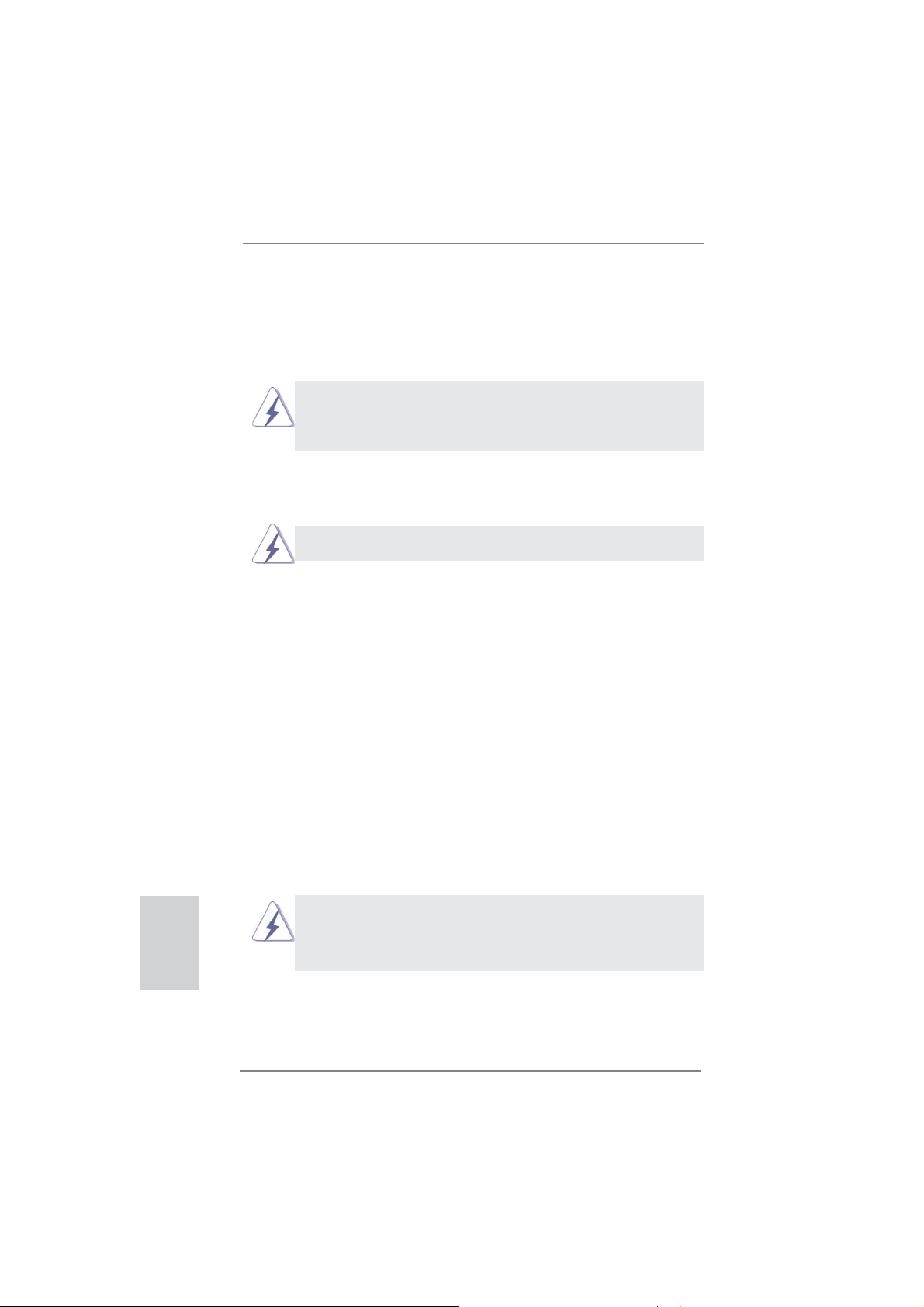
motherboard. Failure to do so may cause physical injuries to you and
damages to motherboard components.
Make sure to unplug the power cord before installing or removing the
2.1 Screw Holes
Place screws into the holes indicated by circles to secure the motherboard to the
chassis.
Do not over-tighten the screws! Doing so may damage the motherboard.
2.2 Pre-installation Precautions
Take note of the following precautions before you install motherboard components
or change any motherboard settings.
1. Unplug the power cord from the wall socket before touching any
components.
2. To avoid damaging the motherboard’s components due to static
electricity, NEVER place your motherboard directly on the carpet
or the like. Also remember to use a grounded wrist strap or touch a
safety grounded object before you handle the components.
3. Hold components by the edges and do not touch the ICs.
4. Whenever you uninstall any component, place it on a grounded antistatic pad or in the bag that comes with the component.
5. When placing screws into the screw holes to secure the motherboard to the chassis, please do not over-tighten the screws! Doing
so may damage the motherboard.
English
12
Before you install or remove any component, ensure that the power is
switched off or the power cord is detached from the power supply. Failure to do
so may cause severe damage to the motherboard, peripherals, and/or
components.
ASRock P75 Pro3 Motherboard
Page 13
2.3 CPU Installation
For the installation of Intel 1155-Pin CPU,
please follow the steps below.
LoadPlate
LoadLever
Before you insert the 1155-Pin CPU into the socket, please check if the
CPU surface is unclean or if there are any bent pins in the socket. Do
not force to insert the CPU into the socket if above situation is found.
Otherwise, the CPU will be seriously damaged.
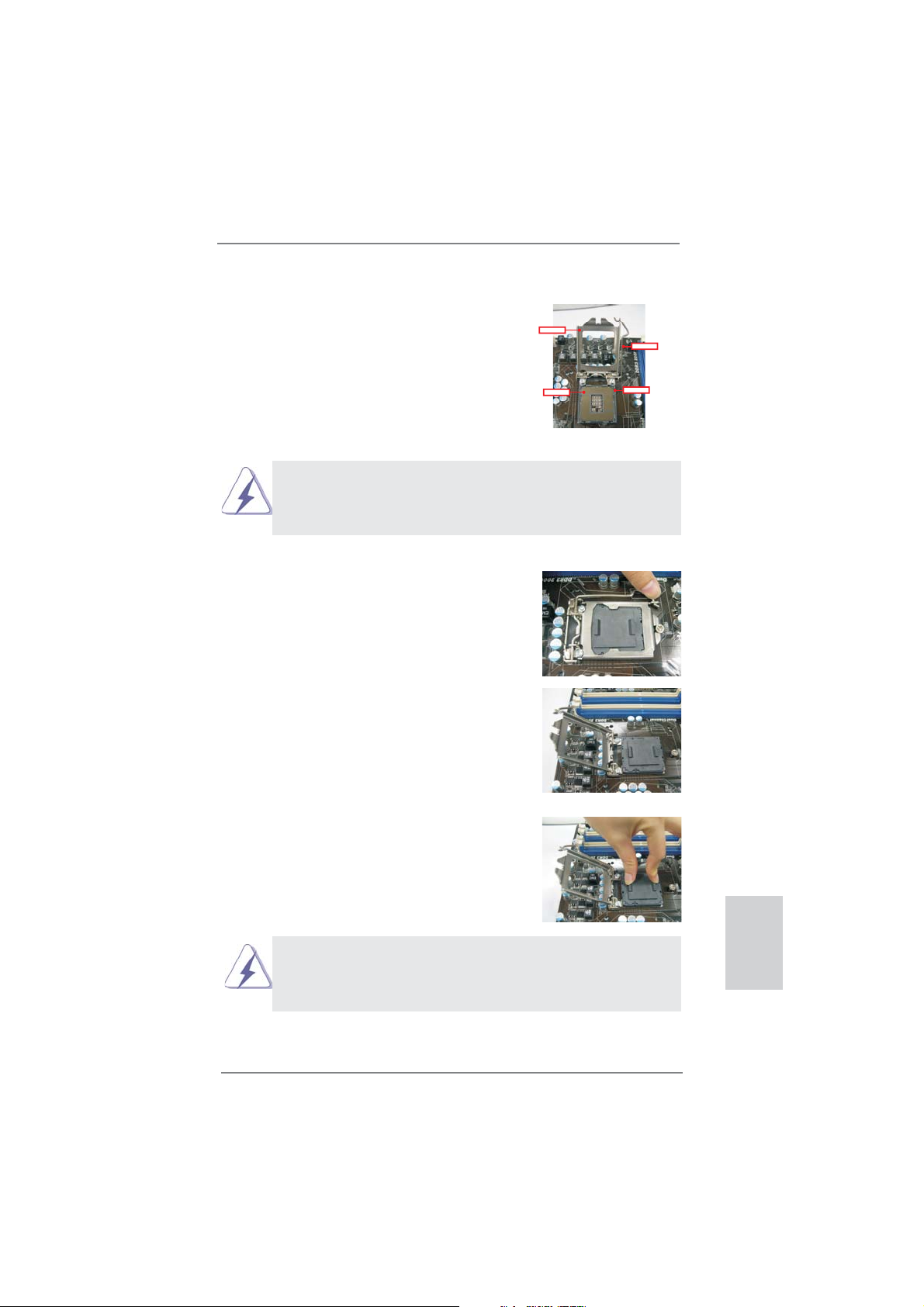
Step 1. Open the socket:
Step 1-1. Disengage the lever by pressing it
down and sliding it out of the hook.
Step 1-2. Keep the lever positioned at about
135 degrees in order to flip up the
load plate.
ContactArray
SocketBody
1155-Pin Socket Overview
Step 2. Remove the PnP Cap (Pick and Place Cap).
1. It is recommended to use the cap tab to handle and avoid kicking
off the PnP cap.
2. This cap must be placed if returning the motherboard for after
service.
ASRock P75 Pro3 Motherboard
English
13
Page 14
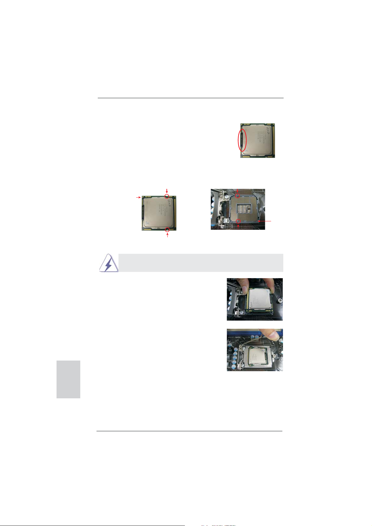
Step 3. Insert the 1155-Pin CPU:
Step 3-1. Hold the CPU by the edge which is
marked with a black line.
Step 3-2. Orient the CPU with the IHS (Inte-
grated Heat Sink) up. Locate Pin1
and the two orientation key notches.
orientation key notch
Pin1
orientation key notch 1155-Pin Socket
1155-Pin CPU
For proper inserting, please ensure to match the two orientation key
notches of the CPU with the two alignment keys of the socket.
Step 3-3. Carefully place the CPU into the
socket by using a purely vertical motion.
Step 3-4. Verify that the CPU is within the sock-
et and properly mated to the orient
keys.
black line
alignment key
Pin1
alignment key
English
14
Step 4. Close the socket:
Step 4-1. Flip the load plate onto the IHS.
Step 4-2. Press down the load lever, and se-
cure it with the load plate tab under
the retention tab.
ASRock P75 Pro3 Motherboard
Page 15

2.4 Installation of CPU Fan and Heatsink
This motherboard is equipped with 1155-Pin socket that supports Intel 1155-Pin
CPUs. Please adopt the type of heatsink and cooling fan compliant with Intel 1155Pin CPU to dissipate heat. Before you install the heatsink, you need to spray thermal interface material between the CPU and the heatsink to improve heat dissipation. Ensure that the CPU and the heatsink are securely fastened and in good contact with each other. Then connect the CPU fan to the CPU_FAN connector (CPU_
FAN1, see page 2, No. 1).
For proper installation, please kindly refer to the instruction manuals of your
CPU fan and heatsink.
Below is an example to illustrate the installation of the heatsink for 1155-Pin CPUs.
Step 1. Apply thermal interface material onto the cen-
ter of the IHS on the socket’s surface.
Apply Thermal
Interface Material
Step 2. Place the heatsink onto the socket. Ensure
that the fan cables are oriented on side closest
Fan cableson side
closest toMB header
to the CPU fan connector on the motherboard
(CPU_FAN1, see page 2, No. 1).
Fastener slots
pointing straightout
Step 3. Align fasteners with the motherboard through-
holes.
Step 4. Rotate the fastener clockwise, then press
down on fastener caps with thumb to install
Press Down
(4 Places)
and lock. Repeat with remaining fasteners.
If you press down the fasteners without rotating them clockwise, the
heatsink cannot be secured on the motherboard.
Step 5. Connect fan header with the CPU fan connector on the motherboard.
Step 6. Secure redundant cable with tie-wrap to ensure the cable does not
interfere with fan operation or contact other components.
Please be noticed that this motherboard supports Combo Cooler
Option (C.C.O.), which provides fl exible options to adopt three dif-
ferent CPU cooler types, Socket LGA 775, LGA 1155 and LGA 1156.
The white throughholes are for Socket LGA
1155/1156 CPU fan.
English
ASRock P75 Pro3 Motherboard
15
Page 16
2.5 Installation of Memory Modules (DIMM)
This motherboard provides two 240-pin DDR3 (Double Data Rate 3) DIMM slots,
and supports Dual Channel Memory Technology. For dual channel configuration,
you always need to install two identical (the same brand, speed, size and chiptype) memory modules in the DDR3 DIMM slots to activate Dual Channel Memory
Technology. Otherwise, it will operate at single channel mode.
1. It is not allowed to install a DDR or DDR2 memory module into a
DDR3 slot; otherwise, this motherboard and DIMM may be
damaged.
2. If you install only one memory module or two non-identical
memory modules, it is unable to activate Dual Channel
Memory Technology.
3. Some DDR3 1GB double-sided DIMMs with 16 chips may not
work on this motherboard. It is not recommended to install them
on this motherboard.
Installing a DIMM
Please make sure to disconnect power supply before adding or
removing DIMMs or the system components.
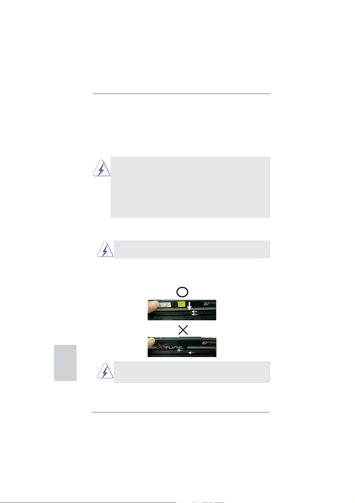
Step 1. Unlock a DIMM slot by pressing the retaining clips outward.
Step 2. Align a DIMM on the slot such that the notch on the DIMM matches the
break on the slot.
English
16
notch
break
notch
break
The DIMM only fi ts in one correct orientation. It will cause permanent
damage to the motherboard and the DIMM if you force the DIMM into
the slot at incorrect orientation.
Step 3. Firmly insert the DIMM into the slot until the retaining clips at both ends
fully snap back in place and the DIMM is properly seated.
ASRock P75 Pro3 Motherboard
Page 17
2.6 Expansion Slots (PCI and PCI Express Slots)
There are 2 PCI slots and 4 PCI Express slots on this motherboard.
PCI slots: PCI slots are used to install expansion cards that have the 32-bit PCI
interface.
PCIE slots:
PCIE1 (PCIE 3.0 x16 slot) is used for PCI Express x16 lane width
graphics cards, or used to install PCI Express graphics cards to support
CrossFireX
PCIE3 (PCIE 2.0 x16 slot) is used for PCI Express x4 lane width graph-
ics cards, or used to install PCI Express graphics cards to support
CrossFireX
PCIE2 / PCIE4 (PCIE 2.0 x1 slot) is used for PCI Express cards with x1
lane width cards, such as Gigabit LAN card, SATA2 card, etc.
1. In single VGA card mode, it is recommended to install a PCI Express
x16 graphics card on PCIE1 slot.
2. In CrossFireXTM mode, please install the PCI Express x16 graphics
cards on PCIE1 and PCIE3 slots. Therefore, PCIE1 will work at x16
bandwidth, while PCIE3 works at x4 bandwidth.
3. Please connect a chassis fan to the motherboard’s chassis fan
connector (CHA_FAN1 or CHA_FAN2) when using multiple graphics
cards for better thermal environment.
4. Only PCIE1 slot supports Gen 3 speed. To run the PCI Express in
Gen 3 speed, please install an Ivy Bridge CPU. If you install a Sandy
Bridge CPU, the PCI Express will run only at PCI Express Gen 2
speed.
TM
.
TM
.
Installing an expansion card
Step 1. Before installing an expansion card, please make sure that the power
supply is switched off or the power cord is unplugged. Please read the
documentation of the expansion card and make necessary hardware
settings for the card before you start the installation.
Step 2. Remove the system unit cover (if your motherboard is already installed
in a chassis).
Step 3. Remove the bracket facing the slot that you intend to use. Keep the
screws for later use.
Step 4. Align the card connector with the slot and press fi rmly until the card is
completely seated on the slot.
Step 5. Fasten the card to the chassis with screws.
Step 6. Replace the system cover
ASRock P75 Pro3 Motherboard
English
17
Page 18
2.7 CrossFireXTM and Quad CrossFireXTM Operation Guide
This motherboard supports CrossFireX
technology offers the most advantageous means available of combining multiple
high performance Graphics Processing Units (GPU) in a single PC. Combining a
range of different operating modes with intelligent software design and an innovative
interconnect mechanism, CrossFireX
performance and image quality in any 3D application. Currently CrossFireXTM is
supported by Windows® XP with Service Pack 2 / VistaTM / 7 OS. Quad CrossFireXTM
is supported by Windows® VistaTM / 7 OS only. Please check AMD’s website for AMD
CrossFireXTM driver updates.
1. If a customer incorrectly confi gures their system they will not see the
performance benefi ts of CrossFireXTM. All three CrossFireXTM components, a
CrossFireXTM Ready graphics card, a CrossFireXTM Ready motherboard and a
CrossFireX
benefi t from the CrossFireXTM multi-GPU platform.
2. If you pair a 12-pipe CrossFireXTM Edition card with a 16-pipe card, both cards
will operate as 12-pipe cards while in CrossFireXTM mode.
TM
Edition co-processor graphics card, must be installed correctly to
TM
and Quad CrossFireXTM. CrossFireXTM
TM
enables the highest possible level of
2.7.1 Installing Two CrossFireXTM-Ready Graphics Cards
Different CrossFireXTM cards may require different methods to enable CrossFireXTM
feature. For other CrossFireXTM cards that AMD has released or will release in the
future, please refer to AMD graphics card manuals for detailed installation guide.
English
18
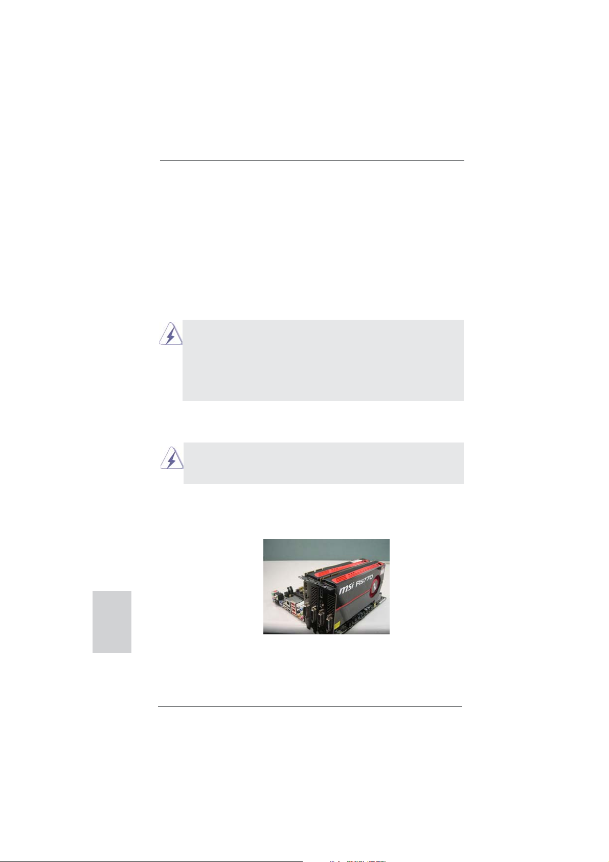
Step 1. Insert one Radeon graphics card into PCIE1 slot and the other Radeon
graphics card to PCIE3 slot. Make sure that the cards are properly seated
on the slots.
ASRock P75 Pro3 Motherboard
Page 19
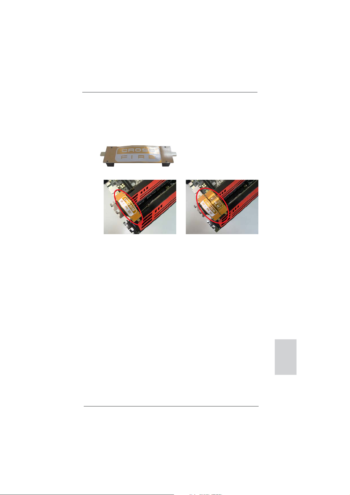
Step 2. Connect two Radeon graphics cards by installing a CrossFire Bridge on
the CrossFire Bridge Interconnects on the top of the Radeon graphics
cards. (The CrossFire Bridge is provided with the graphics card you purchase, not bundled with this motherboard. Please refer to your graphics
card vendor for details.)
CrossFire Bridge
or
Step 3. Connect the DVI monitor cable to the DVI connector on the Radeon graph-
ics card on PCIE1 slot. (You may use the DVI to D-Sub adapter to convert
the DVI connector to D-Sub interface, and then connect the D-Sub monitor
cable to the DVI to D-Sub adapter.)
ASRock P75 Pro3 Motherboard
English
19
Page 20
2.7.2 Driver Installation and Setup
Step 1. Power on your computer and boot into OS.
Step 2. Remove the AMD drivers if you have any VGA drivers installed in your
system.
The Catalyst Uninstaller is an optional download. We recommend using this
utility to uninstall any previously installed Catalyst drivers prior to installation.
Please check AMD’s website for AMD driver updates.
Step 3. Install the required drivers to your system.
For Windows® XP OS:
A. AMD recommends Windows
installed (If you have Windows® XP Service Pack 2 or higher installed
in your system, there is no need to download it again):
http://www.microsoft.com/windowsxp/sp2/default.mspx
B. You must have Microsoft .NET Framework installed prior to
downloading and installing the CATALYST Control Center. Please
check Microsoft’s website for details.
For Windows
®
7 / VistaTM OS:
Install the CATALYST Control Center. Please check AMD’s website for de-
tails.
Step 4. Restart your computer.
Step 5. Install the VGA card drivers to your system, and restart your computer.
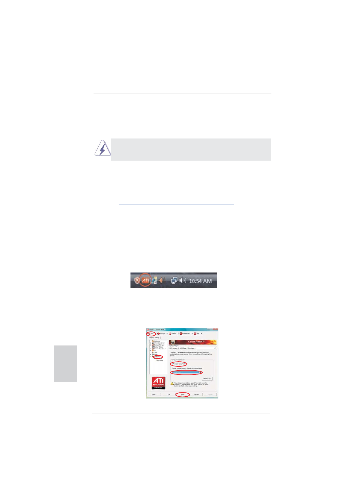
You will fi nd “AMD Catalyst Control Center” on your Windows
®
XP Service Pack 2 or higher to be
®
taskbar.
English
20
AMD Catalyst Control Center
Step 6. Double-click “ATI Catalyst Control Center”. Click “View”, select “CrossFi-
TM
reX
”, and then check the item “Enable CrossFireXTM”. Select “2 GPUs”
and click “Apply”.
ASRock P75 Pro3 Motherboard
Page 21
Although you have selected the option “Enable CrossFireTM”, the CrossFireXTM
function may not work actually. Your computer will automatically reboot. After
restarting your computer, please confi rm whether the option “Enable
CrossFire
select it again, and then you are able to enjoy the benefi ts of CrossFireX
TM
” in “AMD Catalyst Control Center” is selected or not; if not, please
TM
.
Step 7. You can freely enjoy the benefi ts of CrossFireXTM or Quad CrossFireXTM.
* CrossFireXTM appearing here is a registered trademark of AMD Technologies Inc., and is
used only for identifi cation or explanation and to the owners’ benefi t, without intent to infringe.
* For further information of AMD CrossFireX
updates and details.
TM
technology, please check AMD’s website for
ASRock P75 Pro3 Motherboard
English
21
Page 22
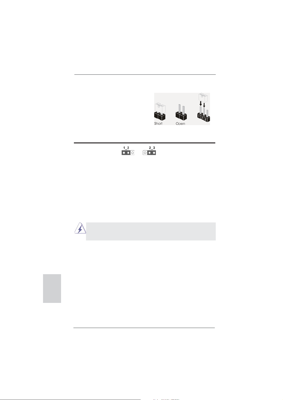
2.8 Jumpers Setup
The illustration shows how jumpers are
setup. When the jumper cap is placed on
pins, the jumper is “Short”. If no jumper cap
is placed on pins, the jumper is “Open”. The
illustration shows a 3-pin jumper whose
pin1 and pin2 are “Short” when jumper cap
is placed on these 2 pins.
Jumper Setting Description
Clear CMOS Jumper
(CLRCMOS1)
(see p.2, No. 22)
Note: CLRCMOS1 allows you to clear the data in CMOS. To clear and reset the
system parameters to default setup, please turn off the computer and unplug
the power cord from the power supply. After waiting for 15 seconds, use a
jumper cap to short pin2 and pin3 on CLRCMOS1 for 5 seconds. However,
please do not clear the CMOS right after you update the BIOS. If you need
to clear the CMOS when you just fi nish updating the BIOS, you must boot
up the system fi rst, and then shut it down before you do the clear-CMOS ac-
tion. Please be noted that the password, date, time, user default profi le, 1394
GUID and MAC address will be cleared only if the CMOS battery is removed.
Clear CMOSDefault
English
22
If you clear the CMOS, the case open may be detected. Please adjust
the BIOS option “Clear Status” to clear the record of previous chassis
intrusion status.
ASRock P75 Pro3 Motherboard
Page 23
2.9 Onboard Headers and Connectors
Onboard headers and connectors are NOT jumpers. Do NOT place
jumper caps over these headers and connectors. Placing jumper caps
over the headers and connectors will cause permanent damage of the
motherboard!
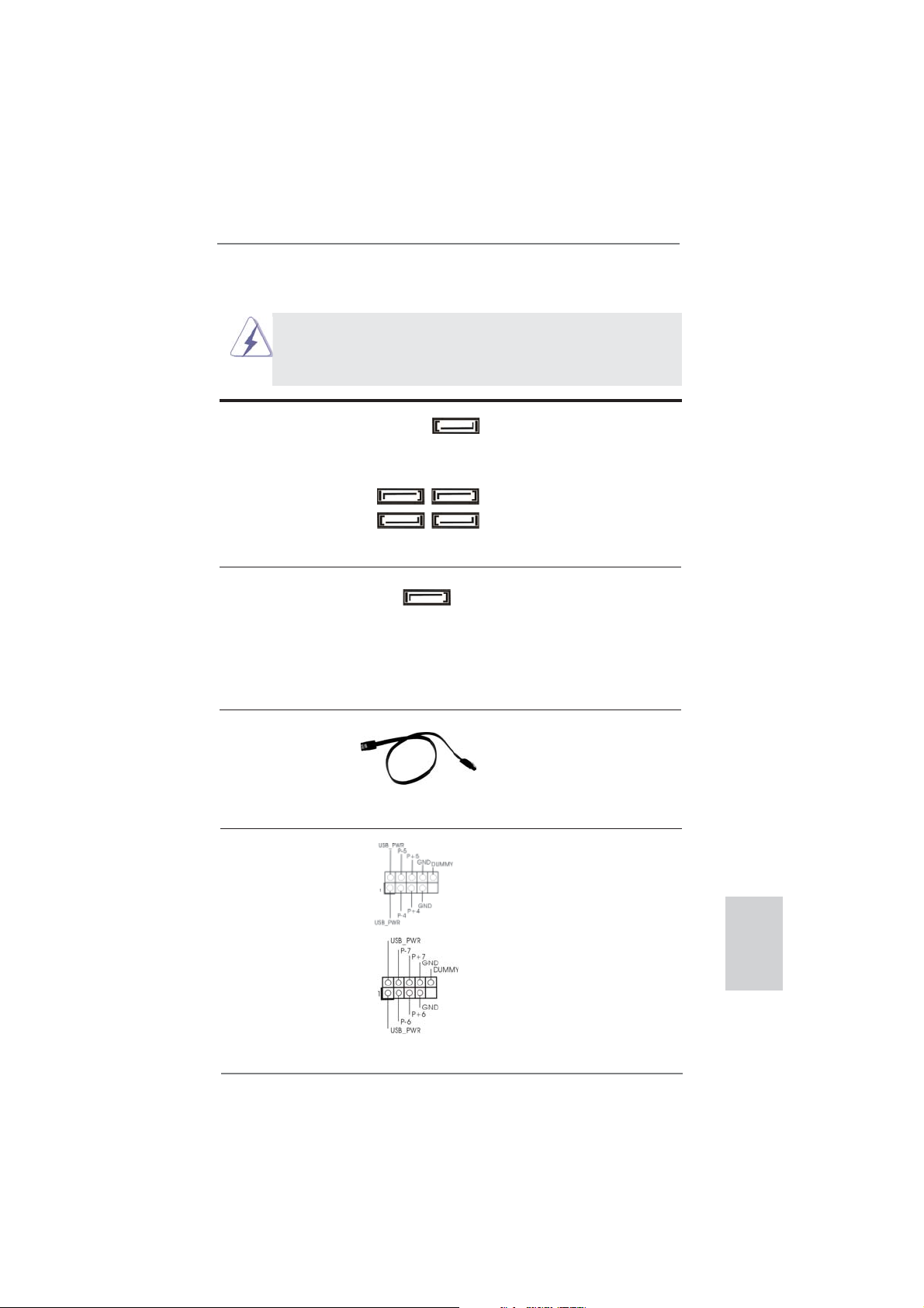
Serial ATA2 Connectors These fi ve Serial ATA2 (SATA2)
(SATA2_1: see p.2, No. 15)
(SATA2_2: see p.2, No. 11)
(SATA2_3: see p.2, No. 14)
(SATA2_4: see p.2, No. 12)
(SATA2_5: see p.2, No. 10)
Serial ATA3 Connector This Serial ATA3 (SATA3)
(SATA3_0: see p.2, No. 9)
cables for internal storage
devices. The current SATA3
interface allows up to 6.0 Gb/s
data transfer rate.
Serial ATA (SATA) Either end of the SATA data
Data Cable cable can be connected to the
(Optional)
SATA / SATA2 / SATA3 hard
disk or the SATA2 / SATA3
connector on this motherboard.
connectors support SATA data
cables for internal storage
devices. The current SATA2
SATA2_2 SATA2_4
SATA2_5
interface allows up to 3.0 Gb/s
data transfer rate.
SATA2_1 SATA2_3
connector supports SATA data
SATA3_0
USB 2.0 Headers Besides four default USB 2.0
(9-pin USB4_5)
(see p.2, No. 18)
ports on the I/O panel, there are
two USB 2.0 headers on this
motherboard. Each USB 2.0
header can support two USB 2.0
ports.
(9-pin USB6_7)
(see p.2, No. 17)
ASRock P75 Pro3 Motherboard
English
23
Page 24
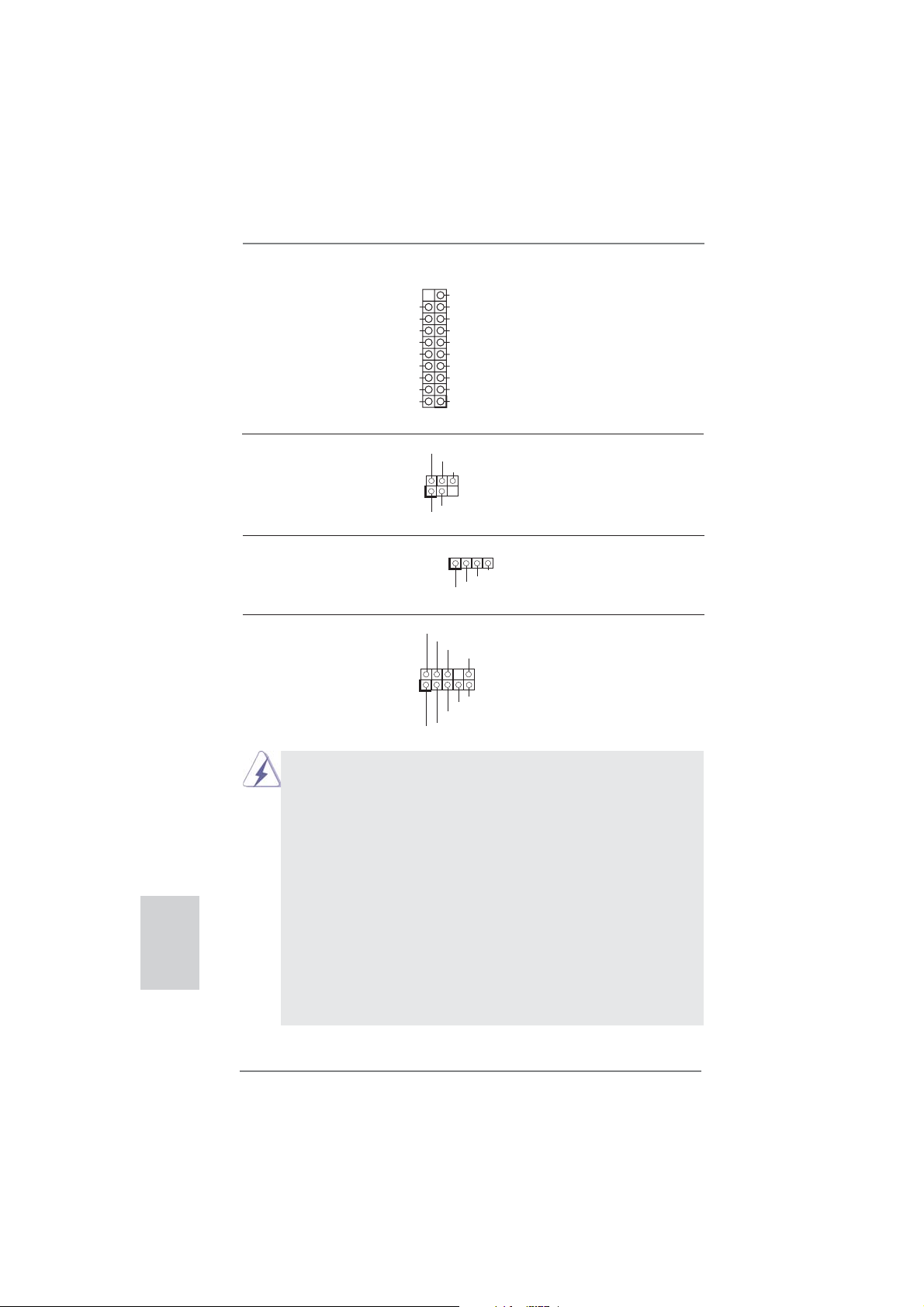
USB 3.0 Header Besides two default USB 3.0
(19-pin USB3_2_3)
(see p.2, No. 6)
motherboard. This USB 3.0
header can support two USB 3.0
ports.
ports on the I/O panel, there is
one USB 3.0 header on this
Vbus
IntA_P4_SSRX-
IntA_P4_SSRX+
GND
IntA_P4_SSTX-
IntA_P4_SSTX+
GND
IntA_P4_D-
IntA_P4_D+
VbusVbus
IntA_P5_SSRX-
IntA_P5_SSRX+
GND
IntA_P5_SSTX-
IntA_P5_SSTX+
GND
IntA_P5_D-
IntA_P5_D+
DUMMY
English
Infrared Module Header This header supports an
(5-pin IR1)
optional wireless transmitting
(see p.2, No. 20)
and receiving infrared module.
IRTX
+5VSB
DUMMY
1
GND
IRRX
Consumer Infrared Module Header This header can be used to
(4-pin CIR1)
(see p.2, No. 19)
connect the remote controller
receiver.
Front Panel Audio Header This is an interface for front
(9-pin HD_AUDIO1)
(see p.2, No. 29)
panel audio cable that allows
convenient connection and
control of audio devices.
1. High Defi nition Audio supports Jack Sensing, but the panel wire on the
chassis must support HDA to function correctly. Please follow the
instruction in our manual and chassis manual to install your system.
2. If you use AC’97 audio panel, please install it to the front panel audio
header as below:
A. Connect Mic_IN (MIC) to MIC2_L.
B. Connect Audio_R (RIN) to OUT2_R and Audio_L (LIN) to OUT2_L.
C. Connect Ground (GND) to Ground (GND).
D. MIC_RET and OUT_RET are for HD audio panel only. You don’t need
to connect them for AC’97 audio panel.
E. To activate the front mic.
For Windows
Select “Mixer”. Select “Recorder”. Then click “FrontMic”.
For Windows® 7 / 7 64-bit / VistaTM / VistaTM 64-bit OS:
Go to the “FrontMic” Tab in the Realtek Control panel. Adjust
“Recording Volume”.
1
GND
IRTX
IRRX
ATX+5VSB
GND
PRESENCE#
MIC_RET
OUT_RET
1
®
XP / XP 64-bit OS:
MIC2_R
MIC2_L
J_SENSE
OUT2_R
OUT2_L
24
ASRock P75 Pro3 Motherboard
Page 25
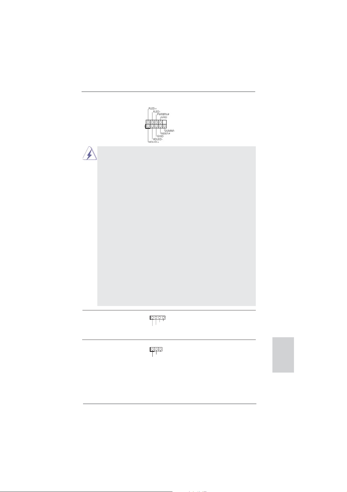
System Panel Header This header accommodates
(9-pin PANEL1)
(see p.2, No. 16)
several system front panel
functions.
Connect the power switch, reset switch and system status indicator on the
chassis to this header according to the pin assignments below. Note the
positive and negative pins before connecting the cables.
PWRBTN (Power Switch):
Connect to the power switch on the chassis front panel. You may confi gure
the way to turn off your system using the power switch.
RESET (Reset Switch):
Connect to the reset switch on the chassis front panel. Press the reset
switch to restart the computer if the computer freezes and fails to perform a
normal restart.
PLED (System Power LED):
Connect to the power status indicator on the chassis front panel. The LED
is on when the system is operating. The LED keeps blinking when the system is in S1/S3 sleep state. The LED is off when the system is in S4 sleep
state or powered off (S5).
HDLED (Hard Drive Activity LED):
Connect to the hard drive activity LED on the chassis front panel. The LED
is on when the hard drive is reading or writing data.
The front panel design may differ by chassis. A front panel module mainly
consists of power switch, reset switch, power LED, hard drive activity LED,
speaker and etc. When connecting your chassis front panel module to this
header, make sure the wire assignments and the pin assign-ments are
matched correctly.
Chassis Speaker Header Please connect the chassis
(4-pin SPEAKER 1)
(see p.2, No. 21)
speaker to this header.
Power LED Header Please connect the chassis
(3-pin PLED1)
(see p.2, No. 24)
power LED to this header to
indicate system power status.
1
+5V
1
PLE D+
DUMMY
DUMMY
PLE D-
PLE D+
SPEAKER
The LED is on when the system
is operating. The LED keeps
blinking in S1/S3 state. The
LED is off in S4 state or S5
state (power off).
ASRock P75 Pro3 Motherboard
English
25
Page 26
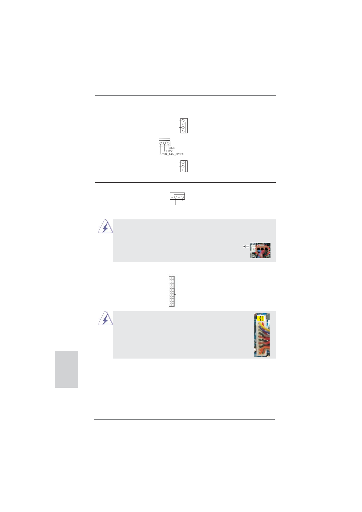
Chassis and Power Fan Connectors Please connect the fan cables
(4-pin CHA_FAN1)
(see p.2, No. 33)
(3-pin CHA_FAN2)
(see p.2, No. 13)
to the fan connectors and match
the black wire to the ground pin.
FAN_SPEED_CONTROL
CHA_FAN_SPEED
+12V
GND
(3-pin PWR_FAN1)
(see p.2, No. 32)
PWR_FAN_SPEED
+12V
GND
English
CPU Fan Connectors Please connect the CPU fan
(4-pin CPU_FAN1)
(see p.2, No. 1)
cable to the connector and
match the black wire to the
ground pin.
4 3 2 1
+12V
FAN_SPEED_CONTROL
CPU_FAN_SPEED
GND
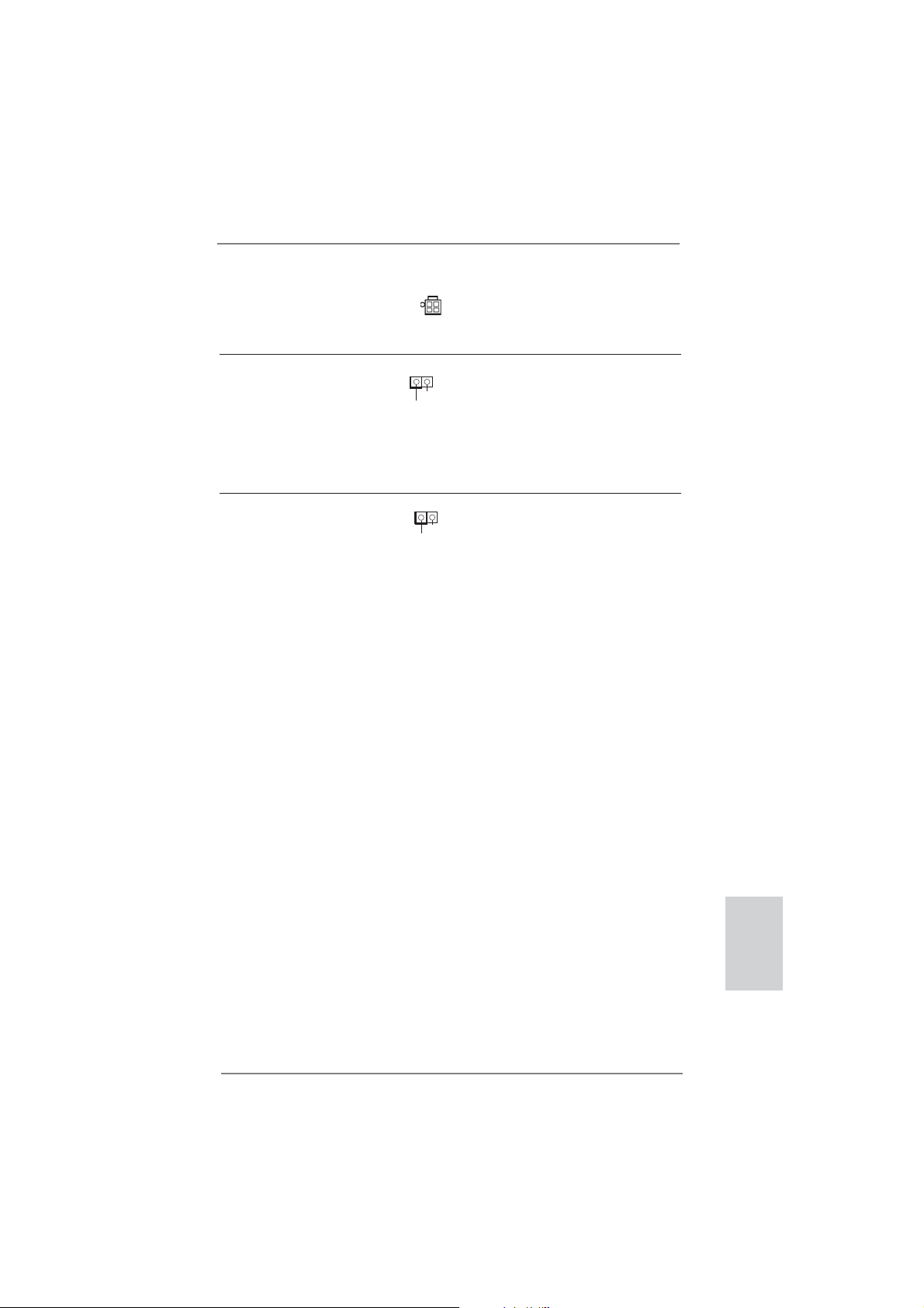
Though this motherboard provides 4-Pin CPU fan (Quiet Fan) support, the 3-Pin
CPU fan still can work successfully even without the fan speed control function.
If you plan to connect the 3-Pin CPU fan to the CPU fan connector on this
motherboard, please connect it to Pin 1-3.
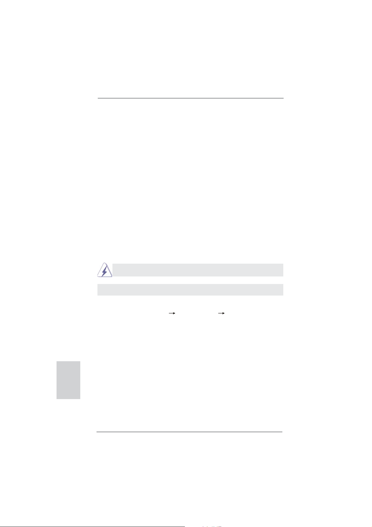
ATX Power Connector Please connect an ATX power
(24-pin ATXPWR1)
(see p.2, No. 5)
supply to this connector.
12 124
13
Though this motherboard provides 24-pin ATX power connector,
Pin 1-3 Connected
3-Pin Fan Installation
12
it can still work if you adopt a traditional 20-pin ATX power supply.
To use the 20-pin ATX power supply, please plug your
power supply along with Pin 1 and Pin 13.
20-Pin ATX Power Supply Installation
1
24
13
26
ASRock P75 Pro3 Motherboard
Page 27
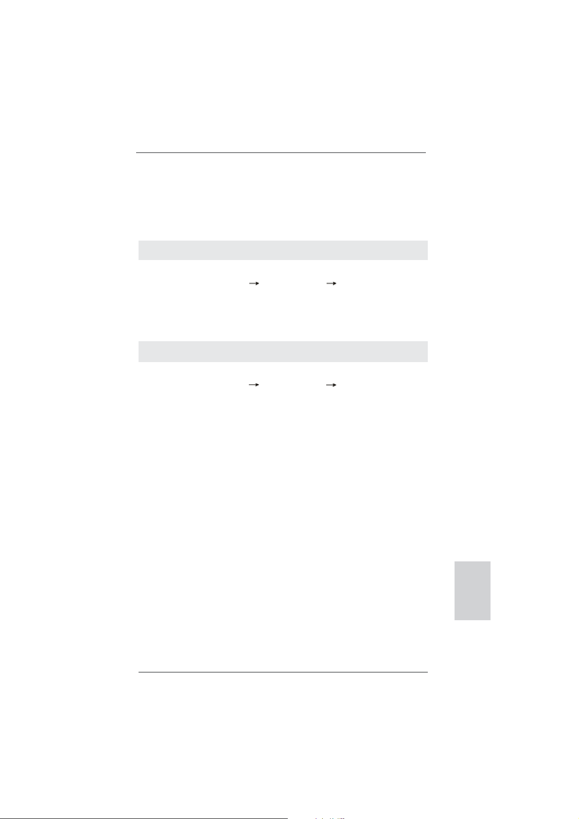
ATX 12V Power Connector Please connect an ATX 12V
(4-pin ATX12V1)
(see p.2, No. 3)
power supply to this connector.
Chassis Intrusion Header This motherboard supports
(2-pin CI1)
CASE OPEN detection feature
(see p.2, No. 23)
that detects if the chassis cover
1
Signal
GND
has been removed. This feature
requires a chassis with chassis
intrusion detection design.
HDMI_SPDIF Header HDMI_SPDIF header, providing
(2-pin HDMI_SPDIF1)
(see p.2, No. 30)
SPDIF audio output to HDMI
VGA card, allows the system to
1
SPDIFOUT
GND
connect HDMI Digital TV/
projector/LCD devices. Please
connect the HDMI_SPDIF
connector of HDMI VGA card to
this header.
ASRock P75 Pro3 Motherboard
English
27
Page 28
2.10 Driver Installation Guide
To install the drivers to your system, please insert the support CD to your optical
drive fi rst. Then, the drivers compatible to your system can be auto-detected and
listed on the support CD driver page. Please follow the order from top to bottom to
install those required drivers. Therefore, the drivers you install can work properly.
2.11 Installing Windows® 7 / 7 64-bit / Vista
TM
/ Vista
TM
64-bit /
XP / XP 64-bit Without RAID Functions
If you want to install Windows® 7 / 7 64-bit / VistaTM / VistaTM 64-bit / XP / XP 64-bit
OS on your SATA / SATA2 / SATA3 HDDs without RAID functions, please follow the
procedures below according to the OS you install.
2.11.1 Installing Windows® XP / XP 64-bit Without RAID
Functions
If you want to install Windows® XP / XP 64-bit OS on your SATA / SATA2 / SATA3
HDDs without RAID functions, please follow the steps below.
AHCI mode is not supported under Windows® XP / XP 64-bit.
Using SATA / SATA2 / SATA3 HDDs without NCQ function
STEP 1: Set Up UEFI.
A. Enter UEFI SETUP UTILITY Advanced screen Storage Confi guration.
B. Set the option “SATA Mode Selection” to [IDE].
STEP 2: Install Windows
®
XP / XP 64-bit OS on your system.
English
28
ASRock P75 Pro3 Motherboard
Page 29
2.11.2 Installing Windows® 7 / 7 64-bit / Vista
TM
/ Vista
TM
64-bit
Without RAID Functions
If you want to install Windows® 7 / 7 64-bit / VistaTM / VistaTM 64-bit OS on your SATA
/ SATA2 / SATA3 HDDs without RAID functions, please follow the steps below.
Using SATA / SATA2 / SATA3 HDDs without NCQ function
STEP 1: Set Up UEFI.
A. Enter UEFI SETUP UTILITY Advanced screen Storage Confi guration.
B. Set the option “SATA Mode Selection” to [IDE].
STEP 2: Install Windows
system.
Using SATA / SATA2 / SATA3 HDDs with NCQ function
STEP 1: Set Up UEFI.
A. Enter UEFI SETUP UTILITY Advanced screen Storage Confi guration.
B. Set the option “SATA Mode Selection” to [AHCI].
STEP 2: Install Windows
system.
®
7 / 7 64-bit / VistaTM / VistaTM 64-bit OS on your
®
7 / 7 64-bit / VistaTM / VistaTM 64-bit OS on your
ASRock P75 Pro3 Motherboard
English
29
Page 30

3. BIOS Information
The Flash Memory on the motherboard stores BIOS Setup Utility. When you start up
the computer, please press <F2> or <Del> during the Power-On-Self-Test (POST)
to enter BIOS Setup utility; otherwise, POST continues with its test routines. If you
wish to enter BIOS Setup after POST, please restart the system by pressing <Ctl>
+ <Alt> + <Delete>, or pressing the reset button on the system chassis. The BIOS
Setup program is designed to be user-friendly. It is a menu-driven program, which
allows you to scroll through its various sub-menus and to select among the predetermined choices. For the detailed information about BIOS Setup, please refer to the
User Manual (PDF fi le) contained in the Support CD.
4. Software Support CD information
®
This motherboard supports various Microsoft
64-bit / VistaTM / Vista
motherboard contains necessary drivers and useful utilities that will enhance motherboard features. To begin using the Support CD, insert the CD into your CD-ROM
drive. It will display the Main Menu automatically if “AUTORUN” is enabled in your
computer. If the Main Menu does not appear automatically, locate and double-click
on the fi le “ASSETUP.EXE” from the BIN folder in the Support CD to display the
menus.
TM
64-bit / XP / XP 64-bit. The Support CD that came with the
Windows® operating systems: 7 / 7
English
30
ASRock P75 Pro3 Motherboard
Page 31

1. Einführung
Wir danken Ihnen für den Kauf des ASRock P75 Pro3 Motherboard, ein zuverlässiges Produkt, welches unter den ständigen, strengen Qualitätskontrollen von ASRock
gefertigt wurde. Es bietet Ihnen exzellente Leistung und robustes Design, gemäß
der Verpflichtung von ASRock zu Qualität und Halbarkeit. Diese Schnellinstallationsanleitung führt in das Motherboard und die schrittweise Installation ein. Details
über das Motherboard fi nden Sie in der Bedienungsanleitung auf der Support-CD.
Da sich Motherboard-Spezifi kationen und BIOS-Software verändern können,
kann der Inhalt dieses Handbuches ebenfalls jederzeit geändert werden. Für
den Fall, dass sich Änderungen an diesem Handbuch ergeben, wird eine neue
Version auf der ASRock-Website, ohne weitere Ankündigung, verfügbar sein.
Die neuesten Grafi kkarten und unterstützten CPUs sind auch auf der ASRock-
Website aufgelistet.
ASRock-Website: http://www.asrock.com
Wenn Sie technische Unterstützung zu Ihrem Motherboard oder spezifi sche
Informationen zu Ihrem Modell benötigen, besuchen Sie bitte unsere Webseite:
www.asrock.com/support/index.asp
1.1 Kartoninhalt
ASRock P75 Pro3 Motherboard
(ATX-Formfaktor: 30.5 cm x 17.8 cm; 12.0 Zoll x 7.0 Zoll)
ASRock P75 Pro3 Schnellinstallationsanleitung
ASRock P75 Pro3 Support-CD
Zwei Serial ATA (SATA) -Datenkabel (optional)
Ein I/O Shield
ASRock erinnert...
Zur besseren Leistung unter Windows® 7 / 7, 64 Bit / Vista
64 Bit empfehlen wir, die Speicherkonfi guration im BIOS auf den AHCI-
Modus einzustellen. Hinweise zu den BIOS-Einstellungen fi nden Sie in
der Bedienungsanleitung auf der mitgelieferten CD.
TM
/ VistaTM
ASRock P75 Pro3 Motherboard
Deutsch
31
Page 32

Deutsch
1.2 Spezifi kationen
Plattform - ATX-Formfaktor: 30.5 cm x 17.8 cm; 12.0 Zoll x 7.0 Zoll
- Alle Feste Kondensatordesign
CPU - Unterstützt Intel
und 2ten Generation im LGA1155-Package
- Unterstützt Intel® Turbo Boost 2.0-Technologie
Chipsatz - Intel® B75
- Unterstützt Intel® Small Business Advantage
- Unterstützt Intel
Connect Technology
Speicher - Dual-Kanal DDR3 Speichertechnologie
- 2 x Steckplätze für DDR3
- Unterstützt DDR3 2200(OC)*/1600/1333/1066 non-ECC,
ungepufferter Speicher (DDR3 1600 mit Intel
Prozessor, DDR3 1333 mit Intel® Sandy Bridge-Prozessor)
* DDR3 2200(OC) wird nur mit Intel® CoreTM i7 3770K Prozessor unterstützt
- Max. Kapazität des Systemspeichers: 16GB
- Unterstützt Intel
Erweiterungs- - 1 x PCI Express 3.0 x16-Steckplätze (PCIE1: x16-Modus)
steckplätze * PCIE 3.0 wird nur mit Intel
unterstützt. Mit Intel® Sandy Bridge-Prozessor wird nur
PCIE 2.0 unterstützt.
- 1 x PCI Express 2.0 x16-Steckplätze (PCIE3: x4-Modus)
- 2 x PCI Express 2.0 x1-Steckplätze
- 2 x PCI-Steckplätze
- Unterstützt AMD
Audio - 7.1 CH HD Audio (Realtek ALC887 Audio Codec)
* Bitte verwenden Sie zur Konfi guration von 7.1-Kanal-Audio
ein HD-Frontpanel-Audiomodul; aktivieren Sie die
Mehrfachkanal-Audiofunktion über den Audiotreiber.
LAN - PCIE x1 Gigabit LAN 10/100/1000 Mb/s
- Realtek RTL8111E
- Unterstützt Wake-On-LAN
- Unterstützt LAN-Kabelerkennung
- Unterstützt energieeffi zientes Ethernet 802.3az
- Unterstützt PXE
E/A-Anschlüsse I/O Panel
an der Rückseite - 1 x PS/2-Tastaturanschluss/Mausanschluss
- 1 x Parallel Port (ECP/EPP Support)
®
CoreTM i7- / i5- / i3-Prozessoren der 3ten
®
Rapid Start Technology und Smart
®
Ivy Bridge-
®
Extreme Memory Profi le (XMP)1.3/1.2
®
Ivy Bridge-Prozessor
TM
Quad CrossFireXTM und CrossFireX
TM
32
ASRock P75 Pro3 Motherboard
Page 33

- 1 x Serieller port: COM 1
- 1 x Koaxial-SPDIF-Ausgang
- 4 x Standard-USB 2.0-Anschlüsse
- 2 x Standard-USB 3.0-Anschlüsse
- 1 x RJ-45 LAN Port mit LED (ACT/LINK LED und SPEED
LED)
- HD Audiobuchse: Audioeingang / Lautsprecher vorne /
Mikrofon
SATA3 - 1 x SATA 3-Anschlüsse (6,0 Gb/s); unterstützt NCQ-, AHCI und Hot Plug Funktionen
USB3.0 - 2 x USB 3.0-Ports an der Rückseite, unterstützt USB
1.1/2.0/3.0 mit bis zu 5 Gb/s
- 1 x USB 3.0-Header (unterstützt zwei USB 3.0-Ports) an der
Vorderseite, unterstützt USB 1.1/2.0/3.0 mit bis zu 5 Gb/s
Anschlüsse - 5 x SATA2 3,0 GB/s-Anschlüsse, unterstützen NCQ-, AHCI-
und Hot Plug Funktionen
- 1 x SATA3 6,0 GB/s-Anschlüsse
- 1 x Infrarot-Modul-Header
- 1 x
- 1 x HDMI_SPDIF-Anschluss
- 1 x Betriebs-LED-Header
- 1 x Verteiler für Gehäuseeindringversuche
- 1 x CPUlüfter-Anschluss (4-pin)
- 2 x Gehäuselüfter-Anschluss (1 x 4-pin, 1 x 3-pin)
- 1 x Stromlüfter-Anschluss (3-pin)
- 24-pin ATX-Netz-Header
- 4-pin anschluss für 12V-ATX-Netzteil
- Anschluss für Audio auf der Gehäusevorderseite
- 2 x USB 2.0-Anschlüsse (Unterstützung 4 zusätzlicher
USB 2.0-Anschlüsse)
- 1 x USB 3.0-Anschlüsse (Unterstützung 2 zusätzlicher
USB 3.0-Anschlüsse)
BIOS - 64Mb AMIs Legal BIOS UEFI mit GUI-Unterstützung
- Unterstützung für “Plug and Play”
- ACPI 1.1-Weckfunktionen
- JumperFree-Modus
- SMBIOS 2.3.1
- CPU Core, DRAM, 1.8V PLL, VTT, VCCSA Stromspannung
Multianpassung
Consumer Infrared-Modul-Header
Deutsch
ASRock P75 Pro3 Motherboard
33
Page 34

CD d’assistance - Treiber, Dienstprogramme, Antivirussoftware (Probeversion),
CyberLink MediaEspresso 6.5-Testversion, ASRock
MAGIX-Multimedia-Suite - OEM
Hardware Monitor - Überwachung der CPU-Temperatur
- Motherboardtemperaturerkennung
- Drehzahlmessung für CPU/Gehäuse/Strom lüfter
- Geräuscharmer CPU-/Gehäuselüfter (ermöglicht die au
tomatische Anpassung der Gehäuselüftergeschwindigkeit
durch CPU-Temperatur)
- Mehrstufi ge Geschwindigkeitssteuerung für CPU/Gehäuse
lüfter
- GEHÄUSE OFFEN-Erkennung
- Spannungsüberwachung: +12V, +5V, +3.3V, Vcore
®
Betriebssysteme - Unterstützt Microsoft
Vista
TM
64-Bit / XP / XP 64-Bit
Windows® 7 / 7 64-Bit / VistaTM /
Zertifi zierungen - FCC, CE, WHQL
- Gemäß Ökodesign-Richtlinie (ErP/EuP) (Stromversorgung
gemäß Ökodesign-Richtlinie (ErP/EuP) erforderlich)
* Für die ausführliche Produktinformation, besuchen Sie bitte unsere Website:
http://www.asrock.com
Deutsch
34
ASRock P75 Pro3 Motherboard
Page 35

1.3 Einstellung der Jumper
Die Abbildung verdeutlicht, wie Jumper
gesetzt werden. Werden Pins durch
Jumperkappen verdeckt, ist der Jumper
“Gebrückt”. Werden keine Pins durch
Jumperkappen verdeckt, ist der Jumper
“Offen”. Die Abbildung zeigt einen 3-Pin
Jumper dessen Pin1 und Pin2 “Gebrückt” sind, bzw. es befi ndet sich eine
Jumper-Kappe auf diesen beiden Pins.
Jumper Einstellun Beschreibung
CMOS löschen
(CLRCMOS1, 3-Pin jumper)
(siehe S.2, No. 22)
Hinweis:
CLRCMOS1 ermöglicht Ihnen die Löschung der Daten im CMOS. Zum
Löschen und Zurücksetzen der Systemparameter auf die Standardeinrichtung
schalten Sie den Computer bitte aus und trennen das Netzkabel von der
Stromversorgung. Warten Sie 15 Sekunden, schließen Sie dann Pin2 und
Pin3 am CLRCMOS1 über einen Jumper fünf Sekunden lang kurz. Sie
sollten das CMOS allerdings nicht direkt nach der BIOS-Aktualisierung
löschen. Wenn Sie das CMOS nach Abschluss der BIOS-Aktualisierung
löschen müssen, fahren Sie zuerst das System hoch. Fahren Sie es dann
vor der CMOS-Löschung herunter. Bitte beachten Sie, dass Kennwort,
Datum, Uhrzeit, benutzerdefi niertes Profi l, 1394 GUID und MAC-Adresse
nur gelöscht werden, wenn die CMOS-Batterie entfernt wird.
DefaultEinstellung
CMOS
löschen
Durch Löschen des CMOS kann erkannt werden, wenn das Gehäuseoffen
ist. Bitte stellen Sie zum Löschen der Aufzeichnung des vorherigenGehäuseindringungsstatus die BIOS-Option “Status leeren” ein.
ASRock P75 Pro3 Motherboard
Deutsch
35
Page 36

1.4 Integrierte Header und Anschlüsse
Integrierte Header und Anschlüsse sind KEINE Jumper. Setzen Sie KEINE Jumperkappen auf diese Header und Anschlüsse. Wenn Sie Jumperkappen auf Header und Anschlüsse setzen, wird das Motherboard
unreparierbar beschädigt!
Seriell-ATA2-Anschlüsse Diese fünf Serial ATA2-
(SATA2_1: siehe S.2 - No. 15)
(SATA2_2: siehe S.2 - No. 11)
(SATA2_3: siehe S.2 - No. 14)
(SATA2_4: siehe S.2 - No. 12)
(SATA2_5: siehe S.2 - No. 10)
ermöglicht eine
Datenübertragungsrate bis
3,0 Gb/s.
Seriell-ATA3-Anschlüsse Dies Serial ATA3-
(SATA3_0: siehe S.2 - No. 9)
unterstützten SATA-Datenkabel
für interne
Massenspeichergeräte. Die
aktuelle SATA3- Schnittstelle
ermöglicht eine
Datenübertragungsrate bis 6,0
Gb/s.
(SATA2-)Verbínder
unterstützten SATA-Datenkabel
für interne
SATA2_2 SATA2_4
Massenspeichergeräte. Die
SATA2_5
aktuelle SATA2- Schnittstelle
SATA2_1 SATA2_3
(SATA3-)Verbínder
SATA3_0
Deutsch
36
Serial ATA- (SATA-) SJedes Ende des SATA
Datenkabel Datenkabels kann an die SATA
(Option)
/ SATA2 / SATA3 Festplatte
oder das SATA2 / SATA3
Verbindungsstück auf dieser
Hauptplatine angeschlossen
werden.
USB 2.0-Header Zusätzlich zu den vier üblichen
(9-pol. USB4_5)
(siehe S.2 - No. 18)
USB 2.0-Ports an den
I/O-Anschlüssen befi nden sich
zwei USB 2.0- Anschlussleisten
am Motherboard. Pro USB 2.0 Anschlussleiste werden zwei
USB 2.0-Ports unterstützt.
ASRock P75 Pro3 Motherboard
Page 37

(9-pol. USB6_7)
(siehe S.2 - No. 17)
USB 3.0-Header Neben zwei Standard-USB
(19-pol. USB3_2_3)
(siehe S.2 - No. 6)
Header an diesem
Motherboard. Dieser USB 3.0 Header kann zwei USB 3.0 Ports unterstützen.
3.0-Ports am E/A-Panel
befi ndet sich ein USB 3.0-
Vbus
IntA_P4_SSRX-
IntA_P4_SSRX+
GND
IntA_P4_SSTX-
IntA_P4_SSTX+
GND
IntA_P4_D-
IntA_P4_D+
Infrarot-Modul-Header Dieser Header unterstützt ein
(5-pin IR1)
optionales, drahtloses Sende-
(siehe S.2 - No. 20)
und Empfangs-Infrarotmodul.
Consumer Infrared-Modul-Header Dieser Header kann zum
(4-pin CIR1)
(siehe S.2 - No. 19)
Anschließen Remote-
Empfänger.
Anschluss für Audio auf Dieses Interface zu einem
der Gehäusevorderseite Audio-Panel auf der Vorder
(9-Pin HD_AUDIO1)
(siehe S.2 - No. 29)
seite Ihres Gehäuses,
ermöglicht Ihnen eine bequeme
Anschlussmöglichkeit und
Kontrolle über Audio-Geräte.
1
IRTX
+5VSB
1
IRRX
GND
PRESENCE#
MIC2_R
MIC2_L
GND
VbusVbus
IntA_P5_SSRX-
IntA_P5_SSRX+
GND
IntA_P5_SSTX-
IntA_P5_SSTX+
GND
IntA_P5_D-
IntA_P5_D+
DUMMY
DUMMY
1
GND
IRTX
IRRX
ATX+5VSB
MIC_RET
OUT_RET
OUT2_L
J_SENSE
OUT2_R
1. High Defi nition Audio unterstützt Jack Sensing (automatische Erkennung falsch
angeschlossener Geräte), wobei jedoch die Bildschirmverdrahtung am Gehäuse
HDA unterstützen muss, um richtig zu funktionieren. Beachten Sie bei der
Installation im System die Anweisungen in unserem Handbuch und im
Gehäusehandbuch.
2. Wenn Sie die AC’97-Audioleiste verwenden, installieren Sie diese wie
nachstehend beschrieben an der Front-Audioanschlussleiste:
A. Schließen Sie Mic_IN (MIC) an MIC2_L an.
B. Schließen Sie Audio_R (RIN) an OUT2_R und Audio_L (LIN) an OUT2_L an.
C. Schließen Sie Ground (GND) an Ground (GND) an.
ASRock P75 Pro3 Motherboard
Deutsch
37
Page 38

Deutsch
D. MIC_RET und OUT_RET sind nur für den HD-Audioanschluss gedacht. Diese
Anschlüsse müssen nicht an die AC’97-Audioleiste angeschlossen werden.
E. So aktivieren Sie das Mikrofon an der Vorderseite.
Bei den Betriebssystemen Windows® XP / XP 64 Bit:
Wählen Sie „Mixer“. Wählen Sie „Recorder“ (Rekorder). Klicken Sie dann auf
„FrontMic“ (Vorderes Mikrofon).
Bei den Betriebssystemen Windows
Wählen Sie im Realtek-Bedienfeld die „FrontMic“ (Vorderes Mikrofon) Registerkarte. Passen Sie die „Recording Volume“ (Aufnahmelautstärke) an.
®
7 / 7 64 Bit / VistaTM / VistaTM 64 Bit:
System Panel-Header Dieser Header unterstützt
(9-pin PANEL1)
(siehe S.2 - No. 16)
Schließen Sie die Ein-/Austaste, die Reset-Taste und die
Systemstatusanzeige am Gehäuse an diesen Header an; befolgen Sie
dabei die nachstehenden Hinweise zur Pinbelegung. Beachten Sie die
positiven und negativen Pins, bevor Sie die Kabel anschließen.
PWRBTN (Ein-/Ausschalter):
RESET (Reset-Taste):
PLED (Systembetriebs-LED):
HDLED (Festplattenaktivitäts-LED):
mehrere Funktion der
Systemvorderseite.
Zum Anschließen des Ein-/Ausschalters an der Frontblende des Gehäu
ses. Sie können konfi gurieren, wie das System mit Hilfe des
Ein-/Ausschalters ausgeschaltet werden können soll.
Zum Anschließen der Reset-Taste an der Frontblende des Gehäuses.
Mit der Reset-Taste können Sie den Computer im Falle eines Absturzes
neu starten.
Zum Anschließen der Betriebsstatusanzeige an der Frontblende des
Gehäuses. Die LED leuchtet, wenn das System in Betrieb ist. Die LED
blinkt, wenn sich das System im Ruhezustand S1/S3 befi ndet. Die LED
schaltet sich aus, wenn sich das System in den Modi S4 befi ndet
oder ausgeschaltet ist (S5).
Zum Anschließen der Festplattenaktivitäts-LED an der Frontblende des
Gehäuses. Die LED leuchtet, wenn die Festplatte Daten liest oder
schreibt.
Das Design der Frontblende kann je nach Gehäuse variiere. Ein
Frontblendenmodul besteht hauptsächlich aus einer Ein-/Austaste, einer
Reset-Taste, einer Betriebs-LED, einer Festplattenaktivitäts-LED,
Lautsprechern, etc. Stellen Sie beim Anschließen des
Frontblendenmoduls Ihres Gehäuses an diesem Header sicher, dass die
Kabel- und Pinbelegung korrekt übereinstimmen.
38
ASRock P75 Pro3 Motherboard
Page 39

Gehäuselautsprecher-Header Schließen Sie den
(4-pin SPEAKER1)
(siehe S.2 - No. 21)
Gehäuselautsprecher an
diesen Header an.
Betriebs-LED-Header Bitte schließen Sie die
(3-pin PLED1)
(siehe S.2 - No. 24)
Betriebs-LED des Gehäuses
zur Anzeige des
1
PLE D+
PLE D+
PLE D-
Systembetriebsstatus an
diesem Header an. Die LED
leuchtet, wenn das System in
Betrieb ist. Die LED blinkt im
S1/S3-Zustand. Im S4- oder
S5-Zustand (ausgeschaltet)
leuchtet die LED nicht.
Gehäuse und Strom lüfteranschlüsse Verbinden Sie die Lüfterkabel
(4-pin CHA_FAN1)
(siehe S.2, No. 33)
den Schutzleiterstift
(3-pin CHA_FAN2)
(siehe S.2, No. 13)
(3-pin PWR_FAN1)
(siehe S.2 - No. 32)
CPU-Lüfteranschluss Verbinden Sie das CPU -
(4-pin CPU_FAN1)
(siehe S.2 - No. 1)
schwarzen Draht dem
mit den Lüfteranschlüssen,
wobei der schwarze Draht an
FAN_SPEED_CONTROL
CHA_FAN_SPEED
+12V
GND
angeschlossenwird.
PWR_FAN_SPEED
+12V
GND
Lüfterkabel mit diesem
Anschluss und passen Sie den
4 3 2 1
+12V
FAN_SPEED_CONTROL
CPU_FAN_SPEED
GND
Erdungsstift an.
Obwohl dieses Motherboard einen vierpoligen CPU-Lüfteranschluss
(Quiet Fan) bietet, können auch CPU-Lüfter mit dreipoligem Anschluss
angeschlossen werden; auch ohne Geschwindigkeitsregulierung. Wenn
Sie einen dreipoligen CPU-Lüfter an den CPU-Lüferanschluss dieses
Motherboards anschließen möchten, verbinden Sie ihn bitte mit den
Pins 1 – 3.
Pins 1–3 anschließen
Lüfter mit dreipoligem Anschluss installieren
ASRock P75 Pro3 Motherboard
Deutsch
39
Page 40

ATX-Netz-Header Verbinden Sie die ATX-
(24-pin ATXPWR1)
(siehe S.2 - No. 5)
Stromversorgung mit diesem
Header.
12 124
13
Deutsch
Obwohl dieses Motherboard einen 24-pol. ATX Stromanschluss bietet, kann es auch mit einem
12
24
24
modifi zierten traditionellen 20-pol. ATX-Netzteil
verwendet werden. Um ein 20-pol. ATX-Netzteil zu
verwenden, stecken Sie den Stecker mit Pin 1 und
Pin 13 ein.
Installation eines 20-pol. ATX-Netzteils
1
13
13
ATX 12V Anschluss Bitte schließen Sie an diesen
(4-pin ATX12V1)
(siehe S.2 - No. 3)
Anschluss die ATX 12V
Stromversorgung an.
Verteiler für Gehäuseeindringversuche Dieses Motherboard unterstützt
(2-pin CI1)
die GEHÄUSE OFFEN-
(siehe S.2 - No. 23)
Erkennungsfunktion,die
feststellt, ob dieGehäuseab-
1
Signal
GND
deckung entferntwurde. Für
diese Funktion istein Ge häuse erforderlich, dasmit ei nem Design zur Erkennung
von Gehäuseeindringver suchenausgestattet ist.
HDMI_SPDIF-Anschluss Der HDMI_SPDIF-Anschluss
(2-pin HDMI_SPDIF1)
(siehe S.2 - No. 30)
stellt einen SPDIF-
Audioausgang für eine HDMI-
1
GND
SPDIFOUT
VGA-Karte zur Verfügung und
ermöglicht den Anschluss von
HDMI-Digitalgeräten wie
Fernsehgeräten, Projektoren,
LCD-Geräten an das System.
Bitte verbinden Sie den
HDMI_SPDIF-Anschluss der
HDMI-VGA-Karte mit diesem
Anschluss.
40
ASRock P75 Pro3 Motherboard
Page 41

2. BIOS-Information
Das Flash Memory dieses Motherboards speichert das Setup-Utility. Drücken Sie
<F2> oder <Del> während des POST (Power-On-Self-Test) um ins Setup zu gelangen, ansonsten werden die Testroutinen weiter abgearbeitet. Wenn Sie ins Setup
gelangen wollen, nachdem der POST durchgeführt wurde, müssen Sie das System
über die Tastenkombination <Ctrl> + <Alt> + <Delete> oder den Reset-Knopf auf
der Gehäusevorderseite, neu starten. Natürlich können Sie einen Neustart auch
durchführen, indem Sie das System kurz ab- und danach wieder anschalten.
Das Setup-Programm ist für eine bequeme Bedienung entwickelt worden. Es ist
ein menügesteuertes Programm, in dem Sie durch unterschiedliche Untermenüs
scrollen und die vorab festgelegten Optionen auswählen können. Für detaillierte
Informationen zum BIOS-Setup, siehe bitte das Benutzerhandbuch (PDF Datei) auf
der Support CD.
3. Software Support CD information
Dieses Motherboard unterstützt eine Reiche von Microsoft® Windows® Betriebssystemen: 7 / 7 64-Bit / VistaTM / Vista
beigefügte Support-CD enthält hilfreiche Software, Treiber und Hilfsprogramme, mit
denen Sie die Funktionen Ihres Motherboards verbessern können Legen Sie die
Support-CD zunächst in Ihr CD-ROM-Laufwerk ein. Der Willkommensbildschirm
mit den Installationsmenüs der CD wird automatisch aufgerufen, wenn Sie die
“Autorun”-Funktion Ihres Systems aktiviert haben.
Erscheint der Wilkommensbildschirm nicht, so “doppelklicken” Sie bitte auf das File
ASSETUP.EXE im BIN-Verzeichnis der Support-CD, um die Menüs aufzurufen.
Das Setup-Programm soll es Ihnen so leicht wie möglich machen. Es ist menügesteuert, d.h. Sie können in den verschiedenen Untermenüs Ihre Auswahl treffen und
die Programme werden dann automatisch installiert.
TM
64-Bit / XP / XP 64-Bit. Die Ihrem Motherboard
ASRock P75 Pro3 Motherboard
Deutsch
41
Page 42

1. Introduction
Merci pour votre achat d’une carte mère ASRock P75 Pro3, une carte mère très
fi able produite selon les critères de qualité rigoureux de ASRock. Elle offre des
performances excellentes et une conception robuste conformément à l’engagement
d’ASRock sur la qualité et la fi abilité au long terme.
Ce Guide d’installation rapide présente la carte mère et constitue un guide
d’installation pas à pas. Des informations plus détaillées concernant la carte
mère pourront être trouvées dans le manuel l’utilisateur qui se trouve sur le CD
d’assistance.
Les spécifi cations de la carte mère et le BIOS ayant pu être mis à jour, le
contenu de ce manuel est sujet à des changements sans notifi cation. Au
cas où n’importe qu’elle modifi cation intervenait sur ce manuel, la version
mise à jour serait disponible sur le site web ASRock sans nouvel avis.
Vous trouverez les listes de prise en charge des cartes VGA et CPU
également sur le site Web ASRock.
Site web ASRock, http://www.asrock.com
Si vous avez besoin de support technique en relation avec cette carte
mère, veuillez consulter notre site Web pour de plus amples informations
particulières au modèle que vous utilisez.
www.asrock.com/support/index.asp
1.1 Contenu du paquet
Carte mère ASRock P75 Pro3
(Facteur de forme ATX: 12.0 pouces x 7.0 pouces, 30.5 cm x 17.8 cm)
Guide d’installation rapide ASRock P75 Pro3
CD de soutien ASRock P75 Pro3
Deux câbles de données de série ATA (SATA) (en option)
Un I/O Panel Shield
Français
42
ASRock vous rappelle...
Pour bénéfi cier des meilleures performances sous Windows® 7 / 7 64 bits
TM
/ Vista
/ VistaTM 64 bits, il est recommandé de paramétrer l'option BIOS
dans Confi guration de stockage en mode AHCI. Pour plus de détails sur
l'installation BIOS, référez-vous au "Mode d'emploi" sur votre CD de support.
ASRock P75 Pro3 Motherboard
Page 43

1.2 Spécifi cations
Format - Facteur de forme ATX:
12.0 pouces x 7.0 pouces, 30.5 cm x 17.8 cm
- Conception à condensateur robuste
CPU - Prend en charge les processeurs Intel
2ème et 3ème génération sur socket LGA1155
- Prend en charge la technologie Intel® Turbo Boost 2.0
Chipsets - Intel® B75
- Supports Intel
®
Small Business Advantage
- Prend en charge les technologies Intel® Rapid Start et Smart
Connect
Mémoire - Compatible avec la Technologie de Mémoire à Canal
Double
- 2 x slots DIMM DDR3
- Supporter DDR3 2200(OC)*/1600/1333/1066 non-ECC,
sans amortissement mémoire (DDR3 1600 avec CPU Intel
Ivy Bridge, DDR3 1333 avec CPU Intel
* DDR3 2200(OC) n’est pris en charge qu’avec le
processeur Intel® CoreTM i7 3770K
- Capacité maxi de mémoire système: 16GB
- Prend en charge le profi l de mémoire extrême Intel
1.3/1.2
Slot d’extension - 1 x slot PCI Express 3.0 x16 (PCIE1 : mode x16)
* PCIE 3.0 n’est pris en charge qu’avec le processeur Intel
Ivy Bridge. Avec le processeur Intel® Sandy Bridge, seul
PCIE 2.0 est pris en charge.
- 1 x slot PCI Express 2.0 x16 (PCIE3 : mode x4)
- 2 x slot PCI Express 2.0 x1
- 2 x slots PCI
- Prend en charge AMD Quad CrossFireX
Audio - 7,1 CH HD Audio (Realtek ALC887 Audio Codec)
* Pour confi gurer l’audio 7.1 CH, utilisez le module d’audio
du panneau avant HD et activez la fonction audio
multicanal via le pilote audio.
LAN - PCIE x1 Gigabit LAN 10/100/1000 Mb/s
- Realtek RTL8111E
- Support du Wake-On-LAN
- Prise en charge de la détection de câble LAN
- Prend en charge la norme Energy Effi cient Ethernet
(Ethernet à effi cacité énergétique) 802.3az
®
CoreTM i7 / i5 / i3
®
Sandy Bridge)
®
(XMP)
TM
et CrossFireX
®
®
TM
Français
ASRock P75 Pro3 Motherboard
43
Page 44

Français
- Supporte PXE
Panneau arrière I/O Panel
- 1 x port clavier/souris PS/2
- 1 x port parallèle: Support ECP/EPP
- 1 x port série: COM 1
- 1 x Port de sortie coaxial SPDIF
- 4 x ports USB 2.0 par défaut
- 2 x ports USB 3.0 par défaut
- 1 x port LAN RJ-45 avec LED (ACT/LED CLIGNOTANTE et
LED VITESSE)
- Prise HD Audio: Entrée Ligne / Haut-parleur frontal /
Microphone
SATA 3 - 1 x connecteurs SATA3 6,0 Gb/s, prennent en charge les
fonctions NCQ, AHCI et Hot Plug
USB 3.0 - 2 x ports USB3.0 à l’arrière, prennent en charge USB
1.1/2.0/3.0 jusqu’à 5 Gb/s
- 1 x barrette USB3.0 en façade (prend en charge 2 ports
USB 3.0), prend en charge USB 1.1/2.0/3.0 jusqu’à 5 Gb/s
Connecteurs - 5 x connecteurs SATA2, prennent en charge un taux de
transfert de données pouvant aller jusqu’à 3.0Go/s,
supporte NCQ, AHCI et Hot Plug (Branchement à chaud)
- 1 x connecteurs SATA3, prennent en charge un taux de
transfert de données pouvant aller jusqu’à 6.0Go/s
- 1 x En-tête du module infrarouge
- 1 x
- 1 x Connecteur HDMI_SPDIF
- 1 x Connecteur de LED d’alimentation
- 1 x Embase d’intrusion châssis
- 1 x Connecteur pour ventilateur de CPU (br. 4)
- 2 x Connecteur pour ventilateur de Châssis
(1 x br. 4, 1 x br. 3)
- 1 x Connecteur pour ventilateur de pouvoir (br. 3)
- br. 24 connecteur d’alimentation ATX
- br. 4 connecteur d’alimentation 12V ATX
- Connecteur audio panneau avant
- 2 x En-tête USB 2.0 (prendre en charge 4 ports USB 2.0
supplémentaires)
- 1 x En-tête USB 3.0 (prendre en charge 2 ports USB 3.0
supplémentaires)
BIOS - 64Mb AMI UEFI Legal BIOS avec support GUI
- Support du “Plug and Play”
Barrette pour module à infrarouges grand public
44
ASRock P75 Pro3 Motherboard
Page 45

- Compatible pour événements de réveil ACPI 1.1
- Gestion jumperless
- Support SMBIOS 2.3.1
- CPU Core, DRAM, 1.8V PLL, VTT, VCCSA Tension
Multi-ajustement
CD d’assistance - Pilotes, utilitaires, logiciel anti-virus (version d’évaluation),
CyberLink MediaEspresso 6.5 Trial, Suite multimédia
ASRock MAGIX - OEM
Surveillance - Détection de la température de l’UC
système - Mesure de température de la carte mère
- Tachéomètre ventilateur processeur/châssis/pouvoir
ventilateur
- Ventilateur silencieux pour unité centrale/châssis (permet le
réglage automatique de la vitesse du ventilateur pour
châssis, selon la température de l’unité centrale)
- Commande de ventilateur CPU/Châssis à plusieurs
vitesses
- Détection d’OUVERTURE DE BOÎTIER
- Monitoring de la tension: +12V, +5V, +3.3V, Vcore
OS - Microsoft
®
Windows® 7 / 7 64-bit / VistaTM / Vista
TM
64-bit
/ XP / XP 64-bit
Certifi cations - FCC, CE, WHQL
- Prêt pour ErP/EuP (alimentation Prêt pour ErP/EuP requise)
* Pour de plus amples informations sur les produits, s’il vous plaît visitez notre site web:
http://www.asrock.com
ASRock P75 Pro3 Motherboard
Français
45
Page 46

1.3 Réglage des cavaliers
L’illustration explique le réglage des cavaliers. Quand un capuchon est placé sur les
broches, le cavalier est « FERME ». Si aucun capuchon ne relie les broches,le cavalier est « OUVERT ». L’illustration montre un
cavalier à 3 broches dont les broches 1 et 2
sont « FERMEES » quand le capuchon est
placé sur ces 2 broches.
Le cavalier Description
Effacer la CMOS
(CLRCMOS1)
(voir p.2 fi g. 22)
Remarque :
CLRCMOS1 vous permet d’effacer les données du CMOS. Pour effacer
Paramètres
par défaut
et réinitialiser les paramètres du système à la confi guration originale,
veuillez éteindre l’ordinateur et débrancher le cordon d’alimentation de
la prise de courant. Après 15 secondes, utilisez un couvercle de jumper
pour court-circuiter les broches pin2 et pin3 de CLRCMOS1 pendant
secondes. Veuillez cependant ne pas effacer le CMOS immédiatement
a
près avoir mis à jour le BIOS. Si vous avez besoin d’effacer le CMOS
après avoir mis à jour le BIOS, vous devez allumer en premier le
système, puis l’éteindre avant de continuer avec l’opération d’effacement
du CMOS. Veuillez noter que le mot de passe, la date, l’heure, le profi l
par défaut de l’utilisateur, 1394 GUID et l’adresse MAC seront effacés
seulement si la batterie du CMOS est enlevée.
Effacer la
CMOS
5
Français
46
Si vous effacez la CMOS, il se peut qu’une ouverture du boîtier soitdé-
tectée. Veuillez ajuster l’option du BIOS “Clear Status” (Effacerl’état) pour
effacer la mention d’état d’intrusion dans le châssis.
ASRock P75 Pro3 Motherboard
Page 47

1.4 En-têtes et Connecteurs sur Carte
Les en-têtes et connecteurs sur carte NE SONT PAS des cavaliers.
NE PAS placer les capuchons de cavalier sur ces en-têtes et connecteurs. Le fait de placer les capuchons de cavalier sur les en-têtes
et connecteurs causera à la carte mère des dommages irréversibles!
Connecteurs Série ATA2 Ces cinq connecteurs Série
(SATA2_1: voir p.2 No. 15)
(SATA2_2: voir p.2 No. 11)
(SATA2_3: voir p.2 No. 14)
(SATA2_4: voir p.2 No. 12)
(SATA2_5: voir p.2 No. 10)
transferts de données pouvant
aller jusqu’à 3,0 Gb/s.
Connecteurs Série ATA3 Cette connecteur Série
(SATA3_0: voir p.2 No. 9)
charge les câbles SATA pour
les périphériques de stockage
internes. L’interface SATA3
actuelle permet des taux
transferts de données pouvant
aller jusqu’à 6,0 Gb/s.
ATA2 (SATA2) prennent en
charge les câbles SATA pour
les périphériques de stockage
SATA2_2 SATA2_4
SATA2_5
internes. L’interface SATA2
actuelle permet des taux
SATA2_1 SATA2_3
ATA3 (SATA3) prennent en
SATA3_0
Câble de données Toute cote du cable de data
Série ATA (SATA) SATA peut etre connecte au
(en option)
disque dur SATA / SATA2 /
SATA3 ou au connecteur SATA2
/ SATA3 sur la carte
mere.
En-tête USB 2.0 A côté des quatre ports USB 2.0
(USB4_5 br. 9)
(voir p.2 No. 18)
sur cette carte mère. Chaque
par défaut sur le panneau E/S,
il y a deux embases USB 2.0
Français
embase USB 2.0 peut prendre
en charge 2 ports USB 2.0.
47
ASRock P75 Pro3 Motherboard
Page 48

(USB6_7 br. 9)
(voir p.2 No. 17)
En-tête USB 3.0 En plus des deux ports USB
(USB3_2_3 br. 19)
(voir p.2 No. 6)
sur la carte mère. Cette barrette
USB 3.0 peut prendre en
charge deux ports USB 3.0.
3.0 par défaut sur le panneau
E/S, il y a une barrette USB 3.0
Vbus
IntA_P4_SSRX-
IntA_P4_SSRX+
GND
IntA_P4_SSTX-
IntA_P4_SSTX+
GND
IntA_P4_D-
IntA_P4_D+
En-tête du module infrarouge Cet en-tête supporte un module
(IR1 br. 5)
infrarouge optionnel de transfert
(voir p.2 No. 20)
et de réception sans fi l.
VbusVbus
IntA_P5_SSRX-
IntA_P5_SSRX+
GND
IntA_P5_SSTX-
IntA_P5_SSTX+
GND
IntA_P5_D-
IntA_P5_D+
DUMMY
IRTX
+5VSB
DUMMY
1
GND
IRRX
Barrette pour module à infrarouges grand public Cette barrette peut être utilisée
(CIR1 br.4)
(voir p.2 No. 19)
Connecteur audio panneau C’est une interface pour un
(HD_AUDIO1 br. 9)
(voir p.2 No. 29)
contrôle commodes de
périphériques audio.
pour connecter des récepteur.
câble avant audio en façade qui
permet le branchement et le
1
1
1
ATX+5VSB
GND
GND
PRESENCE#
PRESENCE#
MIC2_R
MIC2_R
MIC2_L
MIC2_L
IRTX
IRRX
MIC_RET
MIC_RET
J_SENSE
J_SENSE
OUT2_R
OUT2_R
GND
OUT_RET
OUT_RET
OUT2_L
OUT2_L
Français
48
1. L’audio à haute défi nition (HDA) prend en charge la détection de fi che, mais le fi l
de panneau sur le châssis doit prendre en charge le HDA pour fonctionner
correctement. Veuillez suivre les instructions dans notre manuel et le manuel de
châssis afi n installer votre système.
2. Si vous utilisez le panneau audio AC’97, installez-le sur l’adaptateur audio
du panneau avant conformément à la procédure ci-dessous:
A. Connectez Mic_IN (MIC) à MIC2_L.
B. Connectez Audio_R (RIN) à OUT2_R et Audio_L (LIN) à OUT2_L.
C. Connectez Ground (GND) à Ground (GND).
ASRock P75 Pro3 Motherboard
Page 49

D. MIC_RET et OUT_RET sont réservés au panneau audio HD. Vous
n’avez pas besoin de les connecter pour le panneau audio AC’97.
E. Pour activer le micro avant.
Pour les systèmes d’exploitation Windows
Sélectionnez “Mixer”. Sélectionnez “Recorder” (Enregistreur). Puis
cliquez sur “FrontMic” (Micro avant).
Pour les systèmes d’exploitation Windows
VistaTM 64 bits :
Allez sur l’onglet “FrontMic” (Micro avant) sur le Panneau de contrôle
Realtek. Ajustez “Recording Volume” (Volume d’enregistrement).
®
XP / XP 64 bits :
®
7 / 7 64 bits / VistaTM /
En-tête du panneau système Cet en-tête permet d’utiliser
(PANEL1 br. 9)
(voir p.2 No. 16)
Connectez l’interrupteur d’alimentation, l’interrupteur de réinitialisation et
l’indicateur d’état du système du châssis sur cette barrette en respectant
l’affectation des broches décrite ci-dessous. Faites attention aux broches
positives et négatives avant de connecter les câbles.
PWRBTN (Interrupteur d’alimentation):
RESET (Interrupteur de réinitialisation):
PLED (DEL alimentation système):
HDLED (DEL activité du disque dur):
plusieurs fonctions du panneau
système frontal.
Connectez ici le connecteur d’alimentation sur le panneau avant du
châssis. Vous pouvez confi gurer la façon de mettre votre système hors
tension avec l’interrupteur d’alimentation.
Connectez ici le connecteur de réinitialisation sur le panneau avant du
châssis. Appuyez sur l’interrupteur de réinitialisation pour redémarrer
l’ordinateur s’il se bloque ou s’il n’arrive pas à redémarrer normalement.
Connectez ici l’indicateur d’état de l’alimentation sur le panneau avant du
châssis. Ce voyant DEL est allumé lorsque le système est en marche.
Le voyant DEL clignote lorsque le système est en mode veille S1/S3. Le
voyant DEL est éteint lorsque le système est en mode veille S4 ou
lorsqu’il est éteint (S5).
Connectez ici le voyant DEL d’activité du disque dur sur le panneau
avant du châssis. Ce voyant DEL est allumé lorsque le disque dur est en
train de lire ou d’écrire des données.
Français
Le design du panneau avant peut varier en fonction du châssis. Un
module de panneau avant consiste principalement en : interrupteur
d’alimentation, interrupteur de réinitialisation, voyant DEL d’alimentation,
ASRock P75 Pro3 Motherboard
49
Page 50

voyant DEL d’activité du disque dur, haut-parleur, etc. Lorsque vous
connectez le panneau avant de votre châssis sur cette barrette, vérifi ez
bien à faire correspondre les fi ls et les broches.
En-tête du haut-parleur Veuillez connecter le
de châssis haut-parleur de châssis sur cet
(SPEAKER1 br. 4)
(voir p.2 No. 21)
en-tête.
Français
50
LED di accensione Collegare il LED di accensione
(PLED1 br. 3)
(voir p.2 Nr. 24)
chassi per indicare lo stato di
alimentazione del sistema. Il
1
PLE D+
PLE D+
PLE D-
LED è acceso quando il sistema
è in funzione. Il LED continua a
lampeggiare in stato S1/S3. Il
LED è spento in stato S4 o S5
(spegnimento).
Connecteur pour châssis et ventilateur Branchez les câbles du
(CHA_FAN1 br. 4)
(voir p.2 No. 33)
ventilateur aux connecteurs
pour ventilateur et faites
correspondre le fi l noir à la
(CHA_FAN2 br. 3)
(voir p.2 No. 13)
(PWR_FAN1 br. 3)
(voir p.2 No. 32)
Connecteur du ventilateur Veuillez connecter le câble de
FAN_SPEED_CONTROL
CHA_FAN_SPEED
+12V
GND
PWR_FAN_SPEED
+12V
GND
4 3 2 1
broche de terre.
de l’UC ventilateur d’UC sur ce
(CPU_FAN1 br. 4)
(voir p.2 No. 1)
connecteur et brancher le fi l
noir sur la broche de terre.
FAN_SPEED_CONTROL
Bien que cette carte mère offre un support de (Ventilateur silencieux
ventilateur de CPU à 4 broches , le ventilateur de CPU à 3 broches peut
bien fonctionner même sans la fonction de commande de vitesse du
ventilateur. Si vous prévoyez de connecter le ventilateur de CPU à 3
broches au connecteur du ventilateur de CPU sur cette carte mère,
veuillez le connecter aux broches 1-3.
GND
+12V
CPU_FAN_SPEED
Installation de ventilateur à 3 broches
Broches 1-3 connectées
ASRock P75 Pro3 Motherboard
Page 51

En-tête d’alimentation ATX Veuillez connecter l’unité
(ATXPWR1 br. 24)
(voir p.2 No. 5)
d’alimentation ATX sur cet en-
tête.
12 124
13
Bien que cette carte mère fournisse un connecteur de
12
24
courant ATX 24 broches, elle peut encore fonctionner
si vous adopter une alimentation traditionnelle ATX 20
broches. Pour utiliser une alimentation ATX 20 broches,
branchez à l’alimentation électrique ainsi qu’aux
broches 1 et 13.
20-Installation de l’alimentation électrique ATX
1
13
Connecteur ATX 12V Veuillez connecter une unité
(ATX12V1 br.4)
(voir p.2 No. 3)
d’alimentation électrique ATX
12V sur ce connecteur.
Embase d’intrusion châssis Cette carte-mère prend
(CI1 br.2)
en charge la détection
(voir p.2 No. 23)
d’OUVERTURE DE BOÎTIER,
1
Signal
GND
quidétecte tout retrait du
capot duchâssis. Cette fonction nécessite un châssis qui a été conçu pour la
détectiond’intrusion dans le
châssis.
Connecteur HDMI_SPDIF Connecteur HDMI_SPDIF,
(HDMI_SPDIF1 2-pin)
(voir p.2 No. 30)
fournissant une sortie audio
SPDIF vers la carte VGA HDMI,
1
GND
SPDIFOUT
et permettant au système de se
connecter au un téléviseur
numérique HDMI /un projecteur
/ un périphérique LCD. Veuillez
brancher le connecteur
HDMI_SPDIF de la carte VGA
HDMI sur ce connecteur.
Français
ASRock P75 Pro3 Motherboard
51
Page 52

2. Informations sur le BIOS
La puce Flash Memory sur la carte mère stocke le Setup du BIOS. Lorsque vous
démarrez l’ordinateur, veuillez presser <F2> ou <Del> pendant le POST (Power-OnSelf-Test) pour entrer dans le BIOS; sinon, le POST continue ses tests de routine. Si
vous désirez entrer dans le BIOS après le POST, veuillez redémarrer le système en
pressant <Ctl> + <Alt> + <Suppr>, ou en pressant le bouton de reset sur le boîtier
du système. Vous pouvez également redémarrer en éteignant le système et en le
rallumant. L’utilitaire d’installation du BIOS est conçu pour être convivial. C’est un
programme piloté par menu, qui vous permet de faire défi ler par ses divers sous-
menus et de choisir parmi les choix prédéterminés. Pour des informations détaillées
sur le BIOS, veuillez consulter le Guide de l’utilisateur (fi chier PDF) dans le CD
technique.
3. Informations sur le CD de support
Cette carte mère supporte divers systèmes d’exploitation Microsoft® Windows®: 7
/ 7 64 bits / VistaTM / Vista
cette carte mère contient les pilotes et les utilitaires nécessaires pour améliorer les
fonctions de la carte mère. Pour utiliser le CD technique, insérez-le dans le lecteur
de CD-ROM. Le Menu principal s’affi che automatiquement si “AUTORUN” est activé
dans votre ordinateur. Si le Menu principal n’apparaît pas automatiquement, localisez dans le CD technique le fi chier “ASSETUP.EXE” dans le dossier BIN et double-
cliquez dessus pour affi cher les menus.
TM
64 bits / XP / XP 64 bits. Le CD technique livré avec
Français
52
ASRock P75 Pro3 Motherboard
Page 53

1. Introduzione
Grazie per aver scelto una scheda madre ASRock P75 Pro3, una scheda madre
affi dabile prodotta secondo i severi criteri di qualità ASRock. Le prestazioni
eccellenti e il design robusto si conformano all’impegno di ASRock nella ricerca
della qualità e della resistenza.
Questa Guida Rapida all’Installazione contiene l’introduzione alla motherboard e la
guida passo-passo all’installazione. Informazioni più dettagliate sulla motherboard si
possono trovare nel manuale per l’utente presente nel CD di supporto.
Le specifi che della scheda madre e il software del BIOS possono essere
aggiornati, pertanto il contenuto di questo manuale può subire
variazioni senza preavviso. Nel caso in cui questo manuale sia
modifi cato, la versione aggiornata sarà disponibile sul sito di ASRock
senza altro avviso. Sul sito ASRock si possono anche trovare le più
recenti schede VGA e gli elenchi di CPU supportate.
ASRock website http://www.asrock.com
Se si necessita dell’assistenza tecnica per questa scheda madre, visitare
il nostro sito per informazioni specifi che sul modello che si sta usando.
www.asrock.com/support/index.asp
1.1 Contenuto della confezione
Scheda madre ASRock P75 Pro3
(ATX Form Factor: 12.0-in x 7.0-in, 30.5 cm x 17.8 cm)
Guida di installazione rapida ASRock P75 Pro3
CD di supporto ASRock P75 Pro3
Due cavi dati Serial ATA (SATA) (opzionali)
Un I/O Shield
ASRock vi ricorda...
Per ottenere migliori prestazioni in Windows® 7 / 7 64-bit / Vista
64-bit, si consiglia di impostare l'opzione BIOS in Storage Confi guration
(Confi gurazione di archiviazione) sulla modalità AHCI. Per l'impostazione
BIOS, fare riferimento a “User Manual” (Manuale dell'utente) nel CD di
supporto per dettagli.
TM
/ VistaTM
ASRock P75 Pro3 Motherboard
Italiano
53
Page 54

Italiano
1.2 Specifi che
Piattaforma - ATX Form Factor: 12.0-in x 7.0-in, 30.5 cm x 17.8 cm
- Design condensatore robusto
Processore - Supporta Intel
pacchetto LGA1155
- Supporto della tecnologia Intel® Turbo Boost 2.0
Chipset - Intel® B75
- Supporta Intel® Small Business Advantage
- Supporta tecnologia Intel
Connect Technology
Memoria - Supporto tecnologia Dual Channel Memory
- 2 x slots DDR3 DIMM
- Supporto DDR3 2200(OC)*/1600/1333/1066 non-ECC,
momoria senza buffer (DDR3 1600 con CPU Intel
DDR3 1333 con CPU Intel® Sandy Bridge)
* DDR3 2200(OC) è supportato soltanto con la CPU Intel®
Core
- Capacità massima della memoria di sistema: 16GB
- Supporto di Intel® XMP (Extreme Memory Profi le)1.3/1.2
Slot di - 1 x Alloggio PCI Express 3.0 x16 (PCIE1 : modalità x16)
espansione * PCIE 3.0 è supportato soltanto con la CPU Intel
Con la CPU Intel® Sandy Bridge, supporta solamente PCIE
2.0.
- 1 x Alloggio PCI Express 2.0 x16 (PCIE3 : modalità x4)
- 2 x Alloggio PCI Express 2.0 x1
- 2 x Alloggio PCI
- Supporto di AMD Quad CrossFireX
Audio - 7.1 CH HD Audio (Realtek ALC887 Audio Codec)
* Per confi gurare l’ audio 7.1 devi usare un modulo frontale HD
e abilitare il Multi Channel Audio dal pannello di controllo dei
tuoi driver.
LAN - PCIE x1 Gigabit LAN 10/100/1000 Mb/s
- Realtek RTL8111E
- Supporta Wake-On-LAN
- Supporta il rilevamento cavo LAN
- Supporto di Energy Effi cient Ethernet 802.3az
- Supporta PXE
Pannello I/O Panel
posteriore I/O - 1 x porta PS/2 per tastiera/mouse
- 1 x porta parallela: supporto ECP/EPP
TM
i7 3770K
®
CoreTM i7 / i5 / i3 di 3a e 2a generazione in un
®
Rapid Start Technology e Smart
®
Ivy Bridge,
®
Ivy Bridge.
TM
e CrossFireX
TM
54
ASRock P75 Pro3 Motherboard
Page 55

- 1 x porta COM
- 1 x porta coassiale SPDIF Out
- 4 x porte USB 2.0 già integrate
- 2 x porte USB 3.0 già integrate
- 1 x porte LAN RJ-45 con LED (LED azione/collegamento e
LED velocità)
- Connettore HD Audio: ingresso linea / cassa frontale /
microfono
SATA 3 - 1 x Connettori SATA3 6,0Gb/s, supporto e delle funzioni NCQ,
AHCI e Hot Plug
USB 3.0 - 2 x porte USB 3.0 posteriori amministrate dal controller,
supporto di USB 1.1/2.0/3.0 fi no a 5Gb/s
- 1 x header USB 3.0 frontale (supporta 4 porte USB 3.0)
amministrato dal controller, supporto di USB 1.1/2.0/3.0 fi no a
5Gb/s
Connettori - 5 x connettori SATA2 3.0Go/s, sopporta e delle funzioni NCQ,
AHCI e Hot Plug
- 1 x connettori SATA3 6.0Go/s
- 1 x Collettore modulo infrarossi
- 1 x
- 1 x connettore HDMI_SPDIF
- 1 x LED di accensione
- 1 x header di intrusione dello chassis
- 1 x Connettore CPU ventola (4-pin)
- 2 x Connettore Chassis ventola (1 x 4-pin, 1 x 3-pin)
- 1 x Connettore Alimentazione ventola (3-pin)
- 24-pin collettore alimentazione ATX
- 4-pin connettore ATX 12V
- Connettore audio sul pannello frontale
- 2 x Collettore USB 2.0 (supporta 4 porte USB 2.0)
- 1 x Collettore USB 3.0 (supporta 2 porte USB 3.0)
BIOS - 64Mb AMI UEFI Legal BIOS con interfaccia di supporto
- Supporta “Plug and Play”
- Compatibile con ACPI 1.1 wake up events
- Supporta jumperfree
- Supporta SMBIOS 2.3.1
- Regolazione multi-voltaggio CPU Core, DRAM, 1.8V PLL,
VTT, VCCSA
CD di - Driver, Utilità, Software AntiVirus (versione di prova),
supporto CyberLink MediaEspresso 6.5 Trial, Suite multimediale
ASRock MAGIX - OEM
Collettore modulo infrarosso consumer
Italiano
ASRock P75 Pro3 Motherboard
55
Page 56

Monitoraggio - Sensore per la temperatura del processore
Hardware - Sensore temperatura scheda madre
- Indicatore di velocità per la ventola del CPU/Chassis/potenza
Alimentazione
- Ventola CPU/Chassis silenziosa (permette la regolazione
automatica della ventola dello chassis in base alla temperatura
della CPU)
- Ventola CPU/chassis con controllo di varie velocità
- Rilevamento CASE APERTO
- Voltaggio: +12V, +5V, +3.3V, Vcore
Compatibilità - Microsoft® Windows® 7 / 7 64 bit / VistaTM / Vista
TM
64 bit / XP /
SO XP 64 bit
Certifi cazioni - FCC, CE, WHQL
- Predisposto ErP/EuP (è necessaria l’alimentazione
predisposta per il sistema ErP/EuP)
* Per ulteriori informazioni, prego visitare il nostro sito internet: http://www.asrock.com
Italiano
56
ASRock P75 Pro3 Motherboard
Page 57

1.3 Setup dei Jumpers
L’illustrazione mostra come sono settati i jumper. Quando il ponticello è posizionato sui pin,
il jumper è “CORTOCIRCUITATO”. Se sui pin
non ci sono ponticelli, il jumper è “APERTO”.
L’illustrazione mostra un jumper a 3 pin in cui il
pin1 e il pin2 sono “CORTOCIRCUITATI” quando il ponticello è posizionato su questi pin.
Jumper Settaggio del Jumper
Resettare la CMOS
(CLRCMOS1)
(vedi p.2 Nr. 22)
Nota:
CLRCMOS1 permette si azzerare i dati nella CMOS. Per cancellare e ripristinare
i
parametri del sistema sulla confi gurazione iniziale, spegnere il computer e
Impostazione
predefi nita
scollegare il cavo d’alimentazione dalla presa di corrente. Attendere 15 secondi,
poi usare un cappuccio jumper per cortocircuitare il pin 2 ed il pin 3 su
CLRCMOS1 per 5 secondi. Tuttavia, si consiglia di non cancellare la CMOS
subito dopo avere aggiornato il BIOS. Se si deve azzerare la CMOS quando si
è completato l’aggiornamento del BIOS, è necessario per prima cosa avviare
il sistema e poi spegnerlo prima di eseguire l’azzeramento della CMOS. Notare che password, data, ore, profi lo utente predefi nito, 1394 GUID e indirizzo
MAC saranno cancellati solo se è rimossa la batteria della CMOS.
Azzeramen-
to CMOS
Se si cancella la CMOS, potrebbe essere rilevata l’apertura del case.Rego-
lare l’opzione del BIOS “Clear Status” (Cancella stato) per cancellarela
registrazione del precedente stato d’intrusione chassis.
ASRock P75 Pro3 Motherboard
Italiano
57
Page 58

1.4 Collettori e Connettori su Scheda
I collettori ed i connettori su scheda NON sono dei jumper. NON installare cappucci per jumper su questi collettori e connettori. L’installazione
di cappucci per jumper su questi collettori e connettori provocherà
danni permanenti alla scheda madre!
Connettori Serial ATA2 Questi cinque connettori Serial
(SATA2_1: vedi p.2 Nr. 15)
(SATA2_2: vedi p.2 Nr. 11)
(SATA2_3: vedi p.2 Nr. 14)
(SATA2_4: vedi p.2 Nr. 12)
(SATA2_5: vedi p.2 Nr. 10)
trasferimento dati fi no a 3.0
Gb/s.
Connettori Serial ATA3 Questo connettori Serial
(SATA3_0: vedi p.2 Nr. 9)
dati SATA per dispositivi di
immagazzinamento interni.
L’interfaccia SATA3 attuale
permette velocità di
trasferimento dati fi no a 6.0
Gb/s.
ATA2 (SATA2) supportano cavi
dati SATA per dispositivi di
immagazzinamento interni.
SATA2_2 SATA2_4
L’interfaccia SATA2 attuale
SATA2_5
permette velocità di
SATA2_1 SATA2_3
ATA3 (SATA3) supportano cavi
SATA3_0
Italiano
58
Cavi dati Serial ATA (SATA) Una o altra estremità del cavo
(Opzionale)
di dati SATA può essere
collegata al disco rigido SATA /
SATA2 / SATA3 o al connettore
di SATA2 / SATA3 su questa
cartolina base.
Collettore USB 2.0 Oltre alle quattro porte USB 2.0
(9-pin USB4_5)
(vedi p.2 Nr. 18)
predefi nite nel pannello I/O, la
scheda madre dispone di due
intestazioni USB 2.0. Ciascuna
intestazione USB 2.0 supporta
(9-pin USB6_7)
(vedi p.2 Nr. 17)
due porte USB 2.0.
ASRock P75 Pro3 Motherboard
Page 59

Collettore USB 3.0 Oltre alle due porte USB 3.0
(19-pin USB3_2_3)
(vedi p.2 Nr. 6)
standard del pannello I/O,
questa scheda madre è dotata
di un header USB 3.0 che
supporta due porte USB 3.0.
Vbus
IntA_P4_SSRX-
IntA_P4_SSRX+
GND
IntA_P4_SSTX-
IntA_P4_SSTX+
GND
IntA_P4_D-
IntA_P4_D+
VbusVbus
IntA_P5_SSRX-
IntA_P5_SSRX+
GND
IntA_P5_SSTX-
IntA_P5_SSTX+
GND
IntA_P5_D-
IntA_P5_D+
DUMMY
Collettore modulo infrarossi Questo collettore supporta
(5-pin IR1)
moduli ad infrarossi optional per
(vedi p.2 Nr. 20)
la trasmissione e la ricezione
senza fi li.
IRTX
+5VSB
DUMMY
1
GND
IRRX
Connettore modulo infrarosso consumer Questo connettore può essere
(4-pin CIR1)
(vedi p.2 Nr. 19)
Connettore audio sul È un’interfaccia per il cavo del
pannello frontale pannello audio. Che consente
(9-pin HD_AUDIO1)
(vedi p.2 Nr. 29)
1. La caratteristica HDA (High Defi nition Audio) supporta il rilevamento dei
connettori, però il pannello dei cavi sul telaio deve supportare la funzione HDA
(High Defi nition Audio) per far sì che questa operi in modo corretto. Attenersi alle
istruzioni del nostro manuale e del manuale del telaio per installare il sistema.
2. Se si utilizza un pannello audio AC’97, installarlo nell’intestazione audio del
pannello anteriore, come indicato di seguito:
Sistema operativo Windows
Selezionare “Mixer”. Selezionare “Recorder” (Registratore). Poi, fare
clic su “FrontMic” (Microfono frontale).
Sistema operativo Windows® 7 / 7 64-bit / VistaTM / VistaTM 64-bit:
Andare alla scheda “FrontMic” (Microfono frontale) del pannello di
controllo Realtek. Regolare la voce “Recording Volume” (Volume
registrazione).
utilizzato per collegare
ricevitore remoto.
connessione facile e controllo
dei dispositivi audio.
1
1
GND
PRESENCE#
MIC2_R
MIC2_L
IRRX
ATX+5VSB
MIC_RET
J_SENSE
OUT2_R
IRTX
OUT_RET
OUT2_L
GND
A. Collegare Mic_IN (MIC) a MIC2_L.
B. Collegare Audio_R (RIN) a OUT2_R e Audio_L (LIN) ad OUT2_L.
C. Collegare Ground (GND) a Ground (GND).
D. MIC_RET e OUT_RET sono solo per il pannello audio HD. Non è
necessario collegarli per il pannello audio AC’97.
E. Per attivare il microfono frontale.
®
XP / XP 64-bit:
ASRock P75 Pro3 Motherboard
Italiano
59
Page 60

Collettore pannello di sistema Questo collettore accomoda
(9-pin PANEL1)
(vedi p.2 Nr. 16)
Collegare l’interruttore d’alimentazione, l’interruttore di ripristino,
l’indicatore di stato del sistema del pannello frontale del telaio a questo
header in base all’assegnazione dei pin defi nita di seguito. Determinare i
pin positivi e negativi prima di collegare i cavi.
PWRBTN (interruttore d’alimentazione):
RESET (interruttore di ripristino):
PLED (LED alimentazione del sistema):
HDLED (LED attività disco rigido):
diverse funzioni di sistema
pannello frontale.
Va collegato all’interruttore d’alimentazione del pannello frontale del
telaio. Usando l’interruttore d’alimentazione si può confi gurare il modo in
cui si spegne il sistema.
Va collegato all’interruttore di ripristino del pannello frontale del telaio.
Premere l’interruttore di ripristino per riavviare il sistema se il computer si
blocca e non riesce ad eseguire un normale riavvio.
Va collegato all’indicatore di stato d’alimentazione del pannello frontale
del telaio. Il LED è acceso quando il sistema è operativo. Il LED continua
a lampeggiare quando il sistema è in stato di standby S1/S3. Il LED è
spento quando il sistema è in stato di sospensione /ibernazione S4
oppure spento (S5).
Va collegato al LED attività disco rigido del pannello frontale del telaio. Il
LED è acceso quando disco rigido legge e scrive i dati.
Italiano
60
Il design del pannello frontale può variare in base ai telai. Il modulo di un
pannello frontale può consistere di: interruttore d’alimentazione,
interruttore di ripristino, LED d’alimentazione, LED attività disco rigido,
casse, eccetera. Quando si collega il modulo del pannello frontale a
questo header, assicurarsi che l’assegnazione dei fi li e dei pin sia fatta
corrispondere in modo appropriato.
Collettore casse telaio Collegare le casse del telaio a
(4-pin SPEAKER1)
(vedi p.2 Nr. 21)
questo collettore.
ASRock P75 Pro3 Motherboard
Page 61

LED di accensione Collegare il LED di accensione
(3-pin PLED1)
(vedi p.2 Nr. 24)
chassi per indicare lo stato di
alimentazione del sistema. Il
1
PLE D+
PLE D+
PLE D-
LED è acceso quando il sistema
è in funzione. Il LED continua a
lampeggiare in stato S1/S3. Il
LED è spento in stato S4 o S5
(spegnimento).
Collettori Chassis ed alimentazione ventola Collegare i cavi della ventola ai
(4-pin CHA_FAN1)
(vedi p.2 Nr. 33)
nero col pin di terra.
(3-pin CHA_FAN2)
(vedi p.2 Nr. 13)
corrispondenti connettori
facendo combaciare il cavo
FAN_SPEED_CONTROL
CHA_FAN_SPEED
+12V
GND
(3-pin PWR_FAN1)
(vedi p.2 Nr. 32)
Connettore ventolina CPU Collegare il cavo della ventolina
(4-pin CPU_FAN1)
(vedi p.2 Nr. 1)
CPU a questo connettore e far
combaciare il fi lo nero al pin
terra.
PWR_FAN_SPEED
+12V
GND
4 3 2 1
+12V
FAN_SPEED_CONTROL
CPU_FAN_SPEED
GND
Sebbene la presente scheda madre disponga di un supporto per ventola CPU a 4
piedini (ventola silenziosa), la ventola CPU a 3 piedini è in grado di funzionare
anche senza la funzione di controllo della velocità della ventola. Se si intende
collegare la ventola CPU a 3 piedini al connettore della ventola CPU su questa
scheda madre, collegarla ai piedini 1-3.
Piedini 1-3 collegati
Installazione della ventola a 3 piedini
Connettore alimentazione ATX Collegare la sorgente
(24-pin ATXPWR1)
(vedi p.2 Nr. 5)
d’alimentazione ATX a questo
connettore.
12 124
13
Italiano
ASRock P75 Pro3 Motherboard
61
Page 62

Con questa scheda madre, c’è in dotazione un
connettore elettrico ATX a 24 pin, ma può funzionare lo
stesso se si adotta un alimentatore ATX a 20 pin. Per
usare l’alimentatore ATX a 20 pin, collegare l’alimentatore
con il Pin 1 e il Pin 13.
12
24
Installazione dell’alimentatore ATX a 20 pin
1
13
Connettore ATX 12 V Collegare un alimentatore ATX
(4-pin ATX12V1)
(vedi p.2 Nr. 3)
12 V a questo connettore.
Header di intrusione dello chassis Questa scheda madre supporta
(2-pin CI1)
la funzione di rilevamento del
(vedi p.2 Nr. 23)
CASE APERTOche rileva che
1
Signal
GND
il coperchio dellochassis è stato
rimosso.Questa funzione
richiede unochassis con
struttura dirilevamento di
intrusione dellochassis.
Header HDMI_SPDIF Header HDMI_SPDIF, con
(2-pin HDMI_SPDIF1)
(vedi p.2 Nr. 30)
uscita audio SPDIF su scheda
HDMI VGA, consente al
1
GND
SPDIFOUT
sistema di collegare dispositivi
per TV digitale HDMI/proiettori/
LCD . Collegare il connettore
HDMI_SPDIF della scheda
VGA HDMI a questo header.
Italiano
62
ASRock P75 Pro3 Motherboard
Page 63

2. Informazioni sul BIOS
La Flash Memory sulla scheda madre contiene le Setup Utility. Quando si avvia il
computer, premi <F2> o <Del> durante il Power-On-Self-Test (POST) della Setup
utility del BIOS; altrimenti, POST continua con i suoi test di routine. Per entrare il
BIOS Setup dopo il POST, riavvia il sistema premendo <Ctl> + <Alt> + <Delete>, o
premi il tasto di reset sullo chassis del sistema. Per informazioni più dettagliate circa
il Setup del BIOS, fare riferimento al Manuale dell’Utente (PDF fi le) contenuto nel cd
di supporto.
3. Software di supporto e informazioni su
CD
Questa scheda madre supporta vari sistemi operativi Microsoft® Windows®: 7 /
7 64-bit / VistaTM / Vista
scheda madre contiene i driver e utilità necessari a potenziare le caratteristiche
della scheda.
Inserire il CD di supporto nel lettore CD-ROM. Se la funzione “AUTORUN” è attivata
nel computer, apparirà automaticamente il Menù principale. Se il Menù principale
non appare automaticamente, posizionarsi sul fi le “ASSETUP.EXE” nel CESTINO
del CD di supporto e cliccare due volte per visualizzare i menù.
TM
64-bit / XP / XP 64-bit. Il CD di supporto a corredo della
ASRock P75 Pro3 Motherboard
Italiano
63
Page 64

1. Introducción
Gracias por su compra de ASRock P75 Pro3 placa madre, una placa de confi anza
producida bajo el control de calidad estricto y persistente. La placa madre provee
realización excelente con un diseño robusto conforme al compromiso de calidad y
resistencia de ASRock.
Esta Guía rápida de instalación contiene una introducción a la placa base y una
guía de instalación paso a paso. Puede encontrar una información más detallada
sobre la placa base en el manual de usuario incluido en el CD de soporte.
Porque las especifi caciones de la placa madre y el software de BIOS
podrían ser actualizados, el contenido de este manual puede ser cambiado
sin aviso. En caso de cualquier modifi cación de este manual, la versión
actualizada estará disponible en el website de ASRock sin previo aviso.
También encontrará las listas de las últimas tarjetas VGA y CPU soportadas
en la página web de ASRock.
Website de ASRock http://www.asrock.com
Si necesita asistencia técnica en relación con esta placa base, visite nuestra
página web con el número de modelo específi co de su placa.
www.asrock.com/support/index.asp
1.1 Contenido de la caja
Placa base ASRock P75 Pro3
(Factor forma ATX: 30,5 cm x 17,8 cm, 12,0” x 7,0”)
Guía de instalación rápida de ASRock P75 Pro3
CD de soporte de ASRock P75 Pro3
Dos cables de datos Serial ATA (SATA) (Opcional)
Una protección I/O
Español
64
ASRock le recuerda...
Para mejorar el rendimiento en Windows® 7 / 7 64 bits / Vista
64 bits, es recomendable establecer la opción del BIOS de la confi gura-
ción de almacenamiento en el modo AHCI. Para obtener detalles sobre
la confi guración del BIOS, consulte el “Manual del usuario” que se en-
cuentra en nuestro CD de soporte.
TM
/ VistaTM
ASRock P75 Pro3 Motherboard
Page 65

1.2 Especifi cación
Plataforma - Factor forma ATX: 30,5 cm x 17,8 cm, 12,0” x 7,0”
- Todo diseño de Capacitor Sólido
Procesador - Admite procesadores Intel
generación en el paquete LGA1155
- Admite la tecnología Intel® Turbo Boost 2.0 Technology
Chipset - Intel® B75
- Soporte Intel® Small Business Advantage
- Admite las tecnologías Intel
Memoria - Soporte de Tecnología de Memoria de Doble Canal
- 2 x DDR3 DIMM slots
- Apoya DDR3 2200(OC)*/1600/1333/1066 non-ECC,
memoria de un-buffered (DDR3 1600 con CPU Intel® Ivy
Bridge, DDR3 1333 con CPU Intel
* DDR3 2200(OC) solamente se admite con una CPU Intel®
CoreTM i7 3770K
- Máxima capacidad de la memoria del sistema: 16GB
- Compatible con Intel
Ranuras de - 1 x ranura PCI Express 3.0 x16 (PCIE1: modo x16)
Expansión * PCIE 3.0 solamente se admite con una CPU Intel® Ivy
Bridge. Con una CPU Intel
admite PCIE 2.0.
- 1 x ranura PCI Express 2.0 x16 (PCIE3: modo x4)
- 2 x ranuras PCI Express 2.0 x1
- 2 x ranuras PCI
- Compatible con AMD Quad CrossFireX
Audio - 7.1 CH HD Audio (Realtek ALC887 Audio Codec)
* Para confi gurar el audio de 7.1-canales, tiene que usar el
módulo de audio HD del panel frontal y habilitar la función
multi-channel en el controlador de audio.
LAN - PCIE x1 Gigabit LAN 10/100/1000 Mb/s
- Realtek RTL8111E
- Soporta Wake-On-LAN
- Admite detección de conexión de cable LAN
- Compatible con Ethernet 802.3az de bajo consumo
energético
- Compatible con PXE
Entrada/Salida I/O Panel
de Panel - 1 x puerto de teclado/ratón PS/2
Trasero - 1 x puerto paralelo: soporta ECP/EPP
®
CoreTM i7 / i5 / i3 de la 3ª y 2ª
®
Rapid Start y Smart Connect
®
Sandy Bridge)
®
Extreme Memory Profi le (XMP)1.3/1.2
®
Sandy Bridge, solamente
TM
y CrossFireX
TM
Español
ASRock P75 Pro3 Motherboard
65
Page 66

Español
- 1 x puerto serial: COM1
- 1 x puerto de salida coaxial SPDIF
- 4 x puertos USB 2.0 predeterminados
- 2 x puertos USB 3.0 predeterminados
- 1 x puerto LAN RJ-45 con LED (LED de ACCIÓN/ENLACE y
LED de VELOCIDAD)
- Conexión de audio: Entrada de línea / Altavoz frontal /
Micrófono
SATA 3 - 1 x conectores SATA3 de 6,0 Gb/s con funciones NCQ, AHCI
y de Hot Plug (conexión en caliente)
USB 3.0 - 2 x puertos USB 3.0 traseros, compatible con USB 1.1/2.0/3.0
de hasta 5 GB/s
- 1 x cabecera USB 3.0 delantera (compatible con 2 puertos
USB 3.0), compatible con USB 1.1/2.0/3.0 de hasta 5 GB/s
Conectores - 5 x conexiones SATA2, admiten una velocidad de
transferencia de datos de hasta 3,0Gb/s, soporta NCQ, AHCI
y de Hot Plug (conexión en caliente)
- 1 x conexiones SATA3, admiten una velocidad de
transferencia de datos de hasta 6,0Gb/s
- 1 x Cabezal de Módulo Infrarrojos
- 1 x
consumidor
- 1 x cabecera HDMI_SPDIF
- 1 x cabecera de indicador LED de encendido
- 1 x Conector de detección de intrusión en el chasis
- 1 x Conector de ventilador de CPU (4-pin)
- 2 x Conector de ventilador de chasis (1 x 4-pin, 1 x 3-pin)
- 1 x Conector de ventilador de alimentacion (3-pin)
- 24-pin cabezal de alimentación ATX
- 4-pin conector de ATX 12V power
- Conector de audio de panel frontal
- 2 x Cabezal USB 2.0 (admite 4 puertos USB 2.0 adicionales)
- 1 x Cabezal USB 3.0 (admite 2 puertos USB 3.0 adicionales)
BIOS - 64Mb AMI BIOS legal UEFI AMI compatible con GUI
- Soporta “Plug and Play”
- ACPI 1.1 compliance wake up events
- Soporta “jumper free”
- Soporta SMBIOS 2.3.1
- Múltiple ajuste de CPU Core, DRAM, 1.8V PLL, VTT, VCCSA
Voltage
Base de conexiones del módulo de infrarrojos para el
66
ASRock P75 Pro3 Motherboard
Page 67

CD de soport - Controladores, utilidades, software de antivirus (versión de
prueba), Prueba de CyberLink MediaEspresso 6.5, Conjunto
multimedia ASRock MAGIX - OEM
Monitor - Sensibilidad a la temperatura del procesador
Hardware - Sensibilidad a la temperatura de la placa madre
- Taquímetros de los ventiladores del procesador y del CPU /
chasis / alimentación
- Ventilador silencioso del procesador y el chasis (ajuste
automático de la velocidad del ventilador del chasis en
función de la temperatura del procesador)
- Control de ajuste de la velocidad del ventilador de la CPU /
chasis
- Control de APERTURA DE CARCASA
- Monitor de Voltaje: +12V, +5V, +3.3V, Vcore
OS - En conformidad con Microsoft
®
Windows® 7 / 7 64 bits /
VistaTM / VistaTM 64 bits / XP / XP 64 bits
Certifi caciones - FCC, CE, WHQL
- Cumple con la directiva ErP/EuP (se requiere una fuente de
alimentación que cumpla con la directiva ErP/EuP)
* Para más información sobre los productos, por favor visite nuestro sitio web:
http://www.asrock.com
ASRock P75 Pro3 Motherboard
Español
67
Page 68

1.3 Setup de Jumpers
La ilustración muestra como los jumpers
son confi gurados. Cuando haya un jumper-
cap sobre los pins, se dice gue el jumper
está “Short”. No habiendo jumper cap sobre
los pins, el jumper está “Open”. La ilustración muesta un jumper de 3 pins cuyo
pin 1 y pin 2 están “Short”.
Jumper Setting
Limpiar CMOS
(CLRCMOS1, jumper de 3 pins)
(ver p.2, N. 22)
Nota:
CLRCMOS1 permite borrar los datos de la memoria CMOS. Para borrar los
parámetros del sistema y restablecer la confi guración predeterminada de los mismos,
apague el equipo y desenchufe el cable de alimentación de la toma de corriente eléctrica. Deje que transcurran 15 segundos y, después, utilice un puente
cortocircuitar los contactos 2 y 3 de CLRCMOS1 durante 5 segundos. No borre
la memoria CMOS justamente después de actualizar el BIOS. Si necesita borrar
la memoria CMOS justamente después de actualizar el BIOS, debe iniciar primero
el sistema y, a continuación, cerrarlo antes de llevar a cabo el borrado de
dicha memoria. Tenga en cuenta que la contraseña, la fecha, la hora, el perfi l
predeterminado del usuario, el GUID 1394 y la dirección MAC solamente se
borrará si la batería CMOS se quita.
Valor predeterminado
Restablecimiento de
la CMOS
para
Español
68
Si borra la memoria CMOS, se puede detectar un caso de abertura.Ajuste
la opción del BIOS “Clear Status” (Borrar estado) para borrar elregistro del
estado de intrusión anterior del chasis.
ASRock P75 Pro3 Motherboard
Page 69

1.4 Cabezales y Conectores en Placas
Los conectores y cabezales en placa NO son puentes. NO coloque
las cubiertas de los puentes sobre estos cabezales y conectores. El
colocar cubiertas de puentes sobre los conectores y cabezales provocará un daño permanente en la placa base.
Conexiones de serie ATA2 Estas cinco conexiones de
(SATA2_1: vea p.2, N. 15)
(SATA2_2: vea p.2, N. 11)
(SATA2_3: vea p.2, N. 14)
(SATA2_4: vea p.2, N. 12)
(SATA2_5: vea p.2, N. 10)
de 3.0 Gb/s.
Conexiones de serie ATA3 Esta conexiones de
(SATA3_0: vea p.2, N. 9)
cables SATA para dispositivos
de almacenamiento internos. La
interfaz SATA2 / SATA3 actual
permite una velocidad de
transferencia de 6.0 Gb/s.
Cable de datos de Cualquier extremo del cable de
serie ATA (SATA) los datos de SATA puede ser
(Opcional)
conectado con el disco duro de
SATA / SATA2 / SATA3 o el
conectador de SATA2 / SATA3
en esta placa base.
serie ATA2 (SATA2) admiten
cables SATA para dispositivos
de almacenamiento internos. La
SATA2_2 SATA2_4
SATA2_5
interfaz SATA2 actual permite
una velocidad de transferencia
SATA2_1 SATA2_3
serie ATA3 (SATA3) admiten
SATA3_0
Cabezal USB 2.0 Además de cuatro puertos USB
(9-pin USB4_5)
(vea p.2, N. 18)
2.0 predeterminados en el
panel de E/S, hay dos bases de
conexiones USB 2.0 en esta
placa base. Cada una de estas
bases de conexiones admite
(9-pin USB6_7)
(vea p.2, N. 17)
dos puertos USB 2.0.
ASRock P75 Pro3 Motherboard
Español
69
Page 70

Cabezal USB 3.0 Además de dos puertos 3.0
(19-pin USB3_2_3)
(vea p.2, N. 6)
cabecera USB 3.0 en esta
placa base. Esta cabecera USB
3.0 admiten dos puertos USB
3.0.
predeterminados situados en el
panel E/S, encontrará una
Vbus
IntA_P4_SSRX-
IntA_P4_SSRX+
GND
IntA_P4_SSTX-
IntA_P4_SSTX+
GND
IntA_P4_D-
IntA_P4_D+
VbusVbus
IntA_P5_SSRX-
IntA_P5_SSRX+
GND
IntA_P5_SSTX-
IntA_P5_SSTX+
GND
IntA_P5_D-
IntA_P5_D+
DUMMY
Español
Cabezal de Módulo Infrarrojos Este cabezal soporta un módulo
(5-pin IR1)
infrarrojos de transmisión y
(vea p.2, N. 20)
recepción wireless opcional.
IRTX
+5VSB
DUMMY
1
GND
IRRX
Base de conexiones del módulo de Esta base de conexiones se
1
GND
PRESENCE#
MIC2_R
MIC2_L
1
ATX+5VSB
MIC_RET
J_SENSE
OUT2_R
IRTX
IRRX
OUT_RET
OUT2_L
GND
®
XP / XP 64-bit:
infrarrojos para el consumidor puede utilizar para conectar
(4-pin CIR1)
(vea p.2, N. 19)
receptor remoto.
Conector de audio de Este es una interface para
panel frontal cable de audio de panel frontal
(9-pin HD_AUDIO1)
(vea p.2, N. 29)
que permite conexión y control
conveniente de apparatos de
Audio.
1. El Audio de Alta Defi nición soporta la detección de conector, pero el
cable de panel en el chasis debe soportar HDA para operar
correctamente. Por favor, siga las instrucciones en nuestro manual y
en el manual de chasis para instalar su sistema.
2. Si utiliza el panel de sonido AC’97, instálelo en la cabecera de sonido
del panel frontal de la siguiente manera:
A. Conecte Mic_IN (MIC) a MIC2_L.
B. Conecte Audio_R (RIN) a OUT2_R y Audio_L (LIN) en OUT2_L.
C. Conecte Ground (GND) a Ground (GND).
D. MIC_RET y OUT_RET son sólo para el panel de sonido HD. No
necesitará conectarlos al panel de sonido AC’97.
E. Activación del micrófono frontal.
En sistemas operativos Windows
Seleccione “Mixer” (Mezclador). Seleccione “Recorder” (Grabadora).
A continuación, haga clic en “FrontMic” (Micrófono frontal).
70
ASRock P75 Pro3 Motherboard
Page 71

En sistemas operativos Windows® 7 / 7 64-bit / VistaTM / VistaTM 64-bit:
Acceda a la fi cha “FrontMic” (Micrófono frontal) del panel de control
Realtek. Ajuste la posición del control deslizante “Recording Volume”
(Volumen de grabación).
Cabezal de panel de sistema Este cabezar acomoda varias
(9-pin PANEL1)
(vea p.2, N. 16)
Conecte el interruptor de alimentación, el interruptor de restablecimiento
y el indicador de estado del sistema situados en el chasis con esta
cabecera en función de las siguientes asignaciones de contacto. Preste
atención a los contactos positivos y negativos antes de conectar los
cables.
PWRBTN (interruptor de alimentación):
RESTABLECER (interruptor de restablecimiento):
PLED (LED de alimentación del sistema):
HDLED (LED de actividad del disco duro):
dunciones de panel frontal de
sistema.
Conecte el interruptor de encendido situado en el panel frontal del
chasis. Puede confi gurar la forma de apagar su sistema mediante el
interruptor de alimentación.
Conecte el interruptor de restablecimiento situado en el panel frontal del
chasis. Pulse el interruptor de restablecimiento para restablecer el
equipo si se bloquea y no se reinicia con normalidad.
Conecte el indicador de estado de alimentación situado en el panel
frontal del chasis. El LED se enciende cuando el sistema esté en
funcionamiento. El LED parpadea cuando el sistema se encuentre en
estado de suspensión S1/S3. El LED se apaga cuando el sistema se
encuentre en estado de suspensión S4 o se apaga (S5).
Conecte el LED de actividad de disco duro situado en el panel frontal
del chasis. El LED se enciende cuando el disco duro esté leyendo o
escribiendo datos.
Es posible que el diseño del panel frontal varíe en función del chasis. Un
módulo del panel frontal consiste principalmente de interruptor de
alimentación, interruptor de restablecimiento, LED de alimentación, LED
de actividad del disco duro, altavoz, etc. Al conectar el módulo del panel
frontal del chasis a esta cabecera, asegúrese de que las asignaciones
de cables y las asignaciones de contactos coincidan correctamente.
ASRock P75 Pro3 Motherboard
Español
71
Page 72

Cabezal del altavoz del chasis Conecte el altavoz del chasis a
(4-pin SPEAKER1)
(vea p.2, N. 21)
su cabezal.
Cabecera de indicador Conecte el indicador LED de
LED de encendido encendido del chasis a esta
(3-pin PLED1)
(vea p.2, N. 24)
cabecera para conocer el
estado de encendido del
1
PLE D+
PLE D+
PLE D-
sistema. El indicador LED se
encenderá si el sistema se
encuentra en funcionamiento.
El indicador LED parpadeará
en el estado S1/S3. El indicador
LED se apagará en los estados
S4 o S5 (apagado).
Conectores de ventilador de Por favor, conecte los cables
chasis / alimentación del ventilador a los conectores
(4-pin CHA_FAN1)
(vea p.2, N. 33)
(3-pin CHA_FAN2)
(vea p.2, N. 13)
(3-pin PWR_FAN1)
(vea p.2, N. 32)
FAN_SPEED_CONTROL
CHA_FAN_SPEED
+12V
GND
PWR_FAN_SPEED
+12V
GND
de ventilador, haciendo coincidir
el cable negro con la patilla de
masa.
Español
72
Conector del ventilador Conecte el cable del ventilador
de la CPU de la CPU a este conector y
(4-pin CPU_FAN1)
(vea p.2, N. 1)
haga coincidir el cable negro
con el conector de tierra.
4 3 2 1
+12V
FAN_SPEED_CONTROL
CPU_FAN_SPEED
GND
Aunque esta placa base proporciona compatibilidad para un ventilador (silencioso)
de procesador de 4 contactos, el ventilador de procesador de 3 contactos seguirá
funcionando correctamente incluso sin la función de control de velocidad de
ventilador. Si pretende enchufar el ventilador de procesador de 3 contactos en el
conector del ventilador de procesador de esta placa base, conéctelo al contacto
1-3.
Contacto 1-3 conectado
Instalación del ventilador de 3 contactos
ASRock P75 Pro3 Motherboard
Page 73

Cabezal de alimentación ATX Conecte la fuente de
(24-pin ATXPWR1)
(vea p.2, N. 5)
alimentación ATX a su cabezal.
12 124
13
A pesar de que esta placa base incluye in conector
de alimentación ATX de 24 pins, ésta puede funcionar
12
24
incluso si utiliza una fuente de alimentación ATX de
20 pins tradicional. Para usar una fuente de
alimentación ATX de 20 pins, por favor, conecte su
fuente de alimentación usando los Pins 1 y 13.
Instalación de una Fuente de Alimentación ATX de 20 Pins
1
13
Cabezal de alimentación ATX 12V Conecte la fuente de
(4-pin ATX12V1)
(vea p.2, N. 3)
alimentación ATX 12V a su
cabezal.
Conector de detección de intrusión en el chasis Esta placa base admite la
(2-pin CI1)
función de control de
(vea p.2, N. 23)
APERTURA DE CARCASA,
quepermite detectar si se
1
Signal
GND
haretirado la cubierta del
chasis.Dicha función requiere
unchasis con diseño
específi copara la detección de
intrusiónen el chasis.
Cabecera HDMI_SPDIF Cabecera HDMI_SPDIF. Ofrece
(HDMI_SPDIF1 de 2 pin)
(vea p.2, N. 30)
VGA HDMI, permite al sistema
una salida SPDIF la tarjeta
1
SPDIFOUT
GND
conectarse a dispositivos de
TV Digital HDMI / proyectores /
Dispositivos LCD. Conecte el
conector HDMI_SPDIF de la
tarjeta VGA HDMI a esta
cabecera.
Español
ASRock P75 Pro3 Motherboard
73
Page 74

2. BIOS Información
El Flash Memory de la placa madre deposita SETUP Utility. Durante el Power-Up
(POST) apriete <F2> o <Del> para entrar en la BIOS. Sí usted no oprime ninguna
tecla, el POST continúa con sus rutinas de prueba. Si usted desea entrar en la
BIOS después del POST, por favor reinicie el sistema apretando <Ctl> + <Alt> +
<Borrar>, o apretando el botón Reset en el panel del ordenador. Para información
detallada sobre como confi gurar la BIOS, por favor refi érase al Manual del Usuario
(archivo PDF) contenido en el CD.
3. Información de Software Support CD
Esta placa-base soporta diversos tipos de sistema operativo Windows®: 7 / 7 64
bits / VistaTM / Vista
la placa-base trae todos los drivers y programas utilitarios para instalar y confi gurar
la placa-base. Para iniciar la instalación, ponga el CD en el lector de CD y se desplegará el Menú Principal automáticamente si «AUTORUN» está habilitado en su
computadora.
Si el Menú Principal no aparece automáticamente, localice y doble-pulse en el archivo “ASSETUP.EXE” para iniciar la instalación.
TM
64 bits / XP / XP 64 bits. El CD de instalación que acompaña
Español
74
ASRock P75 Pro3 Motherboard
Page 75

1. Введение
Благодарим вас за покупку материнской платы ASRock P75 Pro3 надежной материнской
платы, изготовленной в соответствии с постоянно предъявляемыми ASRock жесткими
требованиями к качеству. Она обеспечивает превосходную производительность и
отличается отличной конструкцией, которые отражают приверженность ASRock качеству и
долговечности.
Данное руководство по быстрой установке включает вводную информацию о материнской
плате и пошаговые инструкции по ее установке.
можно найти в руководстве пользователя на компакт-диске поддержки.
Спецификации материнской платы и программное обеспечение
BIOS иногда изменяются, поэтому содержание этого руководства
может обновляться без уведомления. В случае любых модификаций
руководства его новая версия будет размещена на веб-сайте ASRock
без специального уведомления. Кроме того, самые свежие
поддерживаемых модулей памяти и процессоров можно найти на
сайте ASRock.
Адрес веб-сайта ASRock http://www.asrock.com
При необходимости технической поддержки по вопросам данной
материнской платы посетите наш веб-сайт для получения
информации об используемой модели.
www.asrock.com/support/index.asp
1.1 Комплектность
Материнская плата ASRock P75 Pro3
(форм-фактор ATX: 12,0 x 7,0 дюйма / 30,5 x 17,8 см)
Руководство по быстрой установке ASRock P75 Pro3
Компакт-диск поддержки ASRock P75 Pro3
2 x кабель данных Serial ATA (SATA) (дополнительно)
1 x I/O Щит Группы ввода / вывода
Более подробные сведения о плате
списки
ASRock напоминает...
Для обеспечения максимальной производительности ОС Windows
7 / 7 64-bit / Vista
параметра Storage Configuration (Конфигурация запоминающего
устройства) режим AHCI. Подробные сведения о настройке BIOS см.
в руководстве пользователя на прилагаемом компакт-диске.
TM
/ VistaTM 64-bit рекомендуется в BIOS выбрать для
ASRock P75 Pro3 Motherboard
®
Русский
75
Page 76

Русский
1.2 Спецификации
Платформа - форм-фактор ATX: 12,0 x 7,0 дюйма / 30,5 x 17,8 см
- Весь Твердый Конденсаторный проект
Процессор - Поддержка процессора Intel
с помощью разъема для процессоров LGA 1155
- Поддержка технологии Intel
Набор микросхем - Intel® B75
- Поддержка Intel® Small Business Advantage
- Поддержка технологии Intel
Technology
Память - Поддержка технологии Dual Channel DDR3 Memory Technology
- 2 x гнезда DDR3 DIMM
- Поддержите DDR3 2200(OC)*/1600/1333/1066 не- ECC,
безбуферная память (DDR3 1600 с процессором Intel® Ivy Bridge,
DDR3 1333 с процессором Intel® Sandy Bridge)
* DDR3 2200(OC) поставляется только в комплекте с ЦП Intel
CoreTM i7 3770K
- Максимальный объем системной памяти: 16 ГБ
- поддержка профиля Intel® Extreme Memory Profi le (XMP)1.3/1.2
Гнезда - 1 x слота PCI Express 3.0 x16 (PCIE1: режим x16)
расширения * PCIE 3.0 поставляется только в комплекте с ЦП Intel
комплекте с ЦП Intel® Sandy Bridge поставляется только модель
PCIE 2.0.
- 1 x слота PCI Express 2.0 x16 (PCIE3: режим x4)
- 2 x слота PCI Express 2.0 x1
- 2 x слота PCI
- поддержка AMD Quad CrossFireX
Аудиосистема - 7.1 CH HD Аудио HD (Кодер-декодер Аудио Realtek ALC887)
* Чтобы активировать пространственное позиционирование звука
по схеме 7.1, следует задействовать модуль HD Audio на передней
панели и разрешить многопотоковое воспроизведение звука в
настройках аудиодрайвера.
ЛВС - PCIE x 1 Gigabit LAN 10/100/1000 Mb/s
- Realtek RTL8111E
- поддержка Wake-On-LAN
- Поддержка определения кабеля ЛВС
- Поддержка энергосберегающего интерфейса Ethernet 802.3az
- Поддержка PXE
Разъемы ввода- I/O Panel
вывода на задней - 1 x порт клавиатуры/мыши PS/2
панели - 1 x параллельный порт: поддержка ECP/EPP
- 1 x порт COM1
- 1 x порт Coaxial SPDIF Out
- 4 x порта USB 2.0 на задней панели в стандартной конфигурации
- 2 x порта USB 3.0 на задней панели в стандартной конфигурации
- 1 x Разъем RJ-45 LAN с светодиодным индикатором (индикатор
®
CoreTM i7 / i5 / i3 3-го и 2-го поколения
®
Turbo Boost 2.0
®
Rapid Start Technology и Smart Connect
®
®
Ivy Bridge. В
TM
и CrossFireX
TM
76
ASRock P75 Pro3 Motherboard
Page 77

ACT/LINK и индикатор SPEED)
- Соединитель звуковой подсистемы: линейный вход / передняя
колонка / микрофон
SATA 3 - 1 x порта SATA3 со скоростью передачи данных 6,0 Гбит/с, с
аппаратной поддержкой функций NCQ, AHCI и горячего
подключения
USB 3.0 - 2 x задних порта USB 3.0 на контроллере с поддержкой
интерфейсов USB 1.1/2.0/3.0 и скорости передачи данных до 5
Гбит/с
- 1 x передний разъем USB 3.0 (поддерживает 2 порта USB 3.0) с
поддержкой интерфейсов USB 1.1/2.0/3.0
данных до 5 Гбит/с
Колодки и - 5 x разъема SATA2 3,0 Гбит/с, поддержка функций NCQ, AHCI и
плате горячего подключения
- 1 x разъема SATA3 6,0 Гбит/с
- 1 x Колодка инфракрасного модуля
- 1 x
- 1 x Колодка HDMI_SPDIF
- 1 x разъем Power LED
- 1 x разъем датчика открытой крышки
- 1 x соединитель CPU FAN (4-контактный)
- 2 x соединитель Chassis FAN (1 x 4-контактный, 1 x 3-контактный)
- 1 x соединитель Power FAN (3-контактный)
- 24-контактный Колодка питания ATX
- 4-контактный Разъем ATX 12 В
- Аудиоразъем передней панели
- 2 x Колодка USB 2.0 (одна колодка для поддержки 4)
дополнительных портов USB 2.0
- 1 x Колодка USB 3.0 (одна колодка для поддержки 2
дополнительных портов USB 3.0)
BIOS - 64Mb AMI UEFI Legal BIOS с поддержкой rpaфичеckoro интеpфeйca
поль зователя
- поддержка “Plug and Play”
- ACPI 1.1, включение по событиям
- поддержка режима настройки без перемычек
- поддержка SMBIOS 2.3.1
- Регулировка напряжений CPU Core, DRAM, 1.8V PLL, VTT, VCCSA
Компактдиск - Драйверы, служебные программы, антивирусное программное
поддержки обеспечение (пробная версия), Пробная версия программы
CyberLink MediaEspresso 6.5, ASRock MAGIX Multimedia Suite поставщик
Контроль - Датчики температуры процессора
оборудо-вания - Датчики температуры корпуса
- Тахометры вентиляторов CPU/Chassis/Power FAN
- Бесшумный вентилятор ЦП/системного блока (возможность авто
матической настройки скорости вентилятора
соответствии с температурой центрального процессора)
Датчик пользовательского инфракрасного модуля
и скорости передачи
системного блока в
Русский
ASRock P75 Pro3 Motherboard
77
Page 78

- Мультиконтроль скорости вентилятора ЦП/Шасси
- Определение открытой крышки
- Контроль напряжения: +12V, +5V, +3.3V, Vcore
Операцион - Совместимость с Microsoft
Поддержка 64-разрядной версии Vista
ные системы - FCC, CE, WHQL
Сертификаты - Совместимость с ErP/EuP Ready (требуется блок питания
совместимый с ErP/EuP)
* Для детальной информации продукта, пожалуйста посетите наш вебсайт:
http://www.asrock.com
®
Windows® 7 / 7 64-bit / Vista
TM
/ XP / XP 64-bit
TM
1.3 Установка перемычек
Конфигурация перемычек иллюстрируется
на рисунке. Когда перемычка надета на
контакты, они называются “замкнутыми”
(short). Если на контактах перемычки нет,
то они называются “разомкнутыми” (open).
На иллюстрации показана 3-контактная
перемычка, у которой контакты 1 и 2
замкнуты.
Перемычка Установка Описание
Очистка CMOS
(CLRCMOS1,
3-контактная перемычка)
(см. стр. 2, п. 22)
Стандартные Очистка CMOS
/
Русский
Примечание.
78
Контактная колодка CLRCMOS1 позволяет очистить данные CMOS. Для
очистки данных и восстановления заводских системных параметров сначала
выключите компьютер и отсоедините сетевую вилку кабеля питания от
электророзетки. Выждите не менее 15 секунд и колпачковой перемычкой на 5
секунд перемкните штырьки 2 и 3 контактной колодки CLRCMOS1. Однако не
производите очистку CMOS непосредственно после обновления BIOS. Если
необходимо очистить CMOS сразу же после
перед очисткой CMOS, необходимо сначала выполнить загрузку системы, а
затем завершить ее работу. Примите во внимание, что пароль, дата, время,
профиль пользователя по умолчанию, идентификатор 1394 GUID и MAC-адрес
будут очищены только тогда, когда будет извлечена из своего гнезда батарейка
CMOS.
Очистка CMOS может вызвать срабатывание датчика открытой
крышки. Измените опцию «Clear Status» в BIOS, чтобы очистить
записи о предыдущих срабатываниях датчика.
окончания обновления BIOS, то,
ASRock P75 Pro3 Motherboard
Page 79

1.4 Колодки и разъемы на плате
Имеющиеся на плате колодки и разъемы НЕ ЯВЛЯЮТСЯ
контактами для перемычек. НЕ УСТАНАВЛИВАЙТЕ перемычки
на эти колодки и разъемы – это приведет к необратимому
повреждению материнской платы!
Разъемы Serial ATA2 пять соединителя Serial ATA2
(SATA2_1, см. стр. 2, п. 15)
(SATA2_2, см. стр. 2, п. 11)
(SATA2_3, см. стр. 2, п. 14)
(SATA2_4, см. стр. 2, п. 12)
(SATA2_5, см. стр. 2, п. 10)
время интерфейс SATA допускает
скорость передачи данных до \ 3,0
Гбит/с.
Разъемы Serial ATA3 один соединителя Serial ATA3
(SATA3_0, см. стр. 2, п. 9)
подключения внутренних
устройств хранения с
использованием нтерфейсных
кабелей SATA3. В настоящее
скорость передачи данных до \ 6,0
Гбит/с.
предназначаются для
подключения внутренних
устройств хранения с
SATA2_2 SATA2_4
использованием интерфейсных
SATA2_5
кабелей SATA2. В настоящее
SATA2_1 SATA2_3
предназначаются для
SATA3_0
время интерфейс SATA допускает
Информационный Информационный кабель
кабель Serial ATA (SATA) интерфейса SATA / SATA2 / SATA3
(дополнительно)
не является направленным.
Любой из его соединителей может
быть подключен либо к жесткому
диску интерфейса SATA2 / SATA3
либо к материнской плате.
Колодка USB 2.0 Помимо четыре стандартных
(9-контактный USB4_5)
(см. стр. 2, п. 18)
портов USB 2.0 на панели ввода-
вывода, на данной материнской
плате предусмотрено два разъема
USB 2.0. Каждый разъем USB 2.0
поддерживает два порта USB 2.0.
(9-контактный USB6_7)
(см. стр. 2, п. 17)
ASRock P75 Pro3 Motherboard
Русский
79
Page 80

Колодка USB 3.0 Помимо два стандартных
(19-контактный USB3_2_3)
(см. стр. 2, п. 6)
плате предусмотрен один разъем
USB 3.0. Этот разъем USB 3.0
поддерживает два порта USB 3.0.
портов USB 3.0 на панели ввода-
Vbus
IntA_P4_SSRX-
IntA_P4_SSRX+
GND
IntA_P4_SSTX-
IntA_P4_SSTX+
GND
IntA_P4_D-
IntA_P4_D+
VbusVbus
IntA_P5_SSRX-
IntA_P5_SSRX+
GND
IntA_P5_SSTX-
IntA_P5_SSTX+
GND
IntA_P5_D-
IntA_P5_D+
DUMMY
вывода, на данной материнской
Русский
Колодка инфракрасного модуля Данная колодка позволяет
(5-контактный IR1)
(см. стр. 2, п. 20)
подключить дополнительный
модуль беспроводного
инфракрасного
приемопередатчика.
IRTX
+5VSB
DUMMY
1
GND
IRRX
Датчик пользовательского инфракрасного модуля Датчик можно использовать для
(4-контактный CIR1)
(см. стр. 2, п. 19)
Аудиоразъем передней Этот интерфейс предназначен
панели для присоединения аудиокабеля
(9-контактный HD_AUDIO1)
(см. cтр. 2, п. 29)
подключение аудиоустройств и
управление ими.
подключения дистанционный
приемник.
передней панели,
обеспечивающего удобное
1
1
ATX+5VSB
GND
PRESENCE#
MIC2_R
MIC2_L
IRRX
MIC_RET
J_SENSE
OUT2_R
IRTX
OUT_RET
OUT2_L
GND
1. Система High Defi nition Audio поддерживает функцию
автоматического обнаружения разъемов (Jack Sensing), однако
для ее правильной pаботы кабель панели в корпусе должен
поддерживать HDA. При сборке системы следуйте инструкциям,
приведенным в нашем руководстве и руководстве пользователя
для корпуса.
2. Если вы используете аудиопанель AC’97, подключите ее к колодке
аудиоинтерфейса передней панели следующим образом:
A. Подключите выводы
Mic_IN (MIC) к контактам MIC2_L.
B. Подключите выводы Audio_R (RIN) к контактам OUT2_R, а
выводы Audio_L (LIN) к контактам OUT2_L.
C. Подключите выводы Ground (GND) к контактам Ground (GND).
D. Контакты MIC_RET и OUT_RET предназначены только для
аудиопанели HD. При использовании аудиопанели AC’97
подключать их не нужно.
E. Процедура активации микрофона приведена ниже.
Для ОС Windows
®
XP / XP 64-бита:
80
ASRock P75 Pro3 Motherboard
Page 81

Выберите «Mixer» (Микшер). Выберите «Recorder» (Устройство
записи). Затем щелкните «FrontMic» (Передний микрофон).
Для ОС Windows
Перейдите к вкладке «FrontMic» (Передний микрофон) в панели
управления Realtek. Отрегулируйте уровень «Recording
Volume» (Громкость записи).
Колодка системной панели Данная колодка обеспечивает
(9-контактный PANEL1)
(см. стр. 2, п. 16)
Подключите к этому разъему кнопку питания, кнопку сброса и
индикатор состояния системы на корпусе в соответствии с
указанным ниже назначением контактов. При подключении кабелей
необходимо соблюдать полярность положительных и отрицательных
контактов.
PWRBTN (кнопка питания):
Подключите к этим контактам кнопку питания на передней панели
корпуса. Способ выключения системы с
можно настроить.
RESET (кнопка сброса):
Подключите к этим контактам кнопку сброса на передней панели
корпуса. Нажмите кнопку сброса для перезагрузки компьютера, если
компьютер «завис» и нормальную перезагрузку выполнить не
удается.
PLED (индикатор питания системы):
Подключите к этим контактам индикатор состояния питания на
передней панели корпуса
работает. Индикатор мигает, когда система находится в режиме
ожидания S1/S3. Этот индикатор не светится, когда система
находится в режиме ожидания S4, либо выключена (S5).
HDLED (индикатор активности жесткого диска):
Подключите к этим контактам индикатор активности жесткого диска
на передней панели корпуса. Этот индикатор светится, когда
осуществляется
работу нескольких функций
передней панели системы.
®
7 / 7 64-бита, VistaTM / VistaTM 64-бита:
помощью кнопки питания
. Этот индикатор светится, когда система
считывание или запись данных на жестком диске.
Конструкция передней панели может различаться в зависимости от
корпуса. Модуль передней панели в основном состоит из кнопки
питания, кнопки сброса, индикатора питания, индикатора активности
жесткого диска, динамика и т.п. При подключении к этому разъему
модуля передней панели корпуса удостоверьтесь, что
подключаются к соответствующим контактам.
провода
ASRock P75 Pro3 Motherboard
Русский
81
Page 82

Колодка динамика корпуса Подключите к этой колодке
(4-контактный SPEAKER1)
(см. стр. 2, п. 21)
кабель от динамика на корпусе
компьютера.
Русский
разъем Power LED Подключите индикатор Power LED
(3-контактный PLED1)
(см. стр. 2, п. 24)
к этому разъему для отображения
статуса питания системы. Этот
1
PLE D+
PLE D+
PLE D-
светодиод продолжит мигать в
режиме S1/S3. Светодиод будет
выключен в режимах S4 или S5
(система выключена).
Chassis и Power Fan-соединители Подключите кабели вентилятора к
(4-контактный CHA_FAN1)
(см. стр. 2, п. 33)
(3-контактный CHA_FAN2)
(см. стр. 2, п. 13)
(3-контактный PWR_FAN1)
(см. стр. 2, п. 32)
Разъем вентилятора Подключите к этому разъему
процессора кабель вентилятора процессора
(4-контактный CPU_FAN1)
(см. стр. 2, п. 1)
соответствовал контакту земли.
FAN_SPEED_CONTROL
соединителям и присоедините
CHA_FAN_SPEED
+12V
GND
черный шнур к штырю заземления.
так, чтобы черный провод
PWR_FAN_SPEED
+12V
GND
4 3 2 1
+12V
FAN_SPEED_CONTROL
CPU_FAN_SPEED
GND
Данная материнская плата поддерживает вентиляторы процессора с
4-контактным разъемом (функция тихого режима вентилятора), однако
вентиляторы с 3-контактным разъемом также будут успешно работать, хотя
функция управления скоростью вращения вентилятора окажется
недоступной. Если вы хотите подключить вентилятор процессора с
3-контактным разъемом к разъему вентилятора процессора на данной
материнской плате,
для этого следует использовать контакты 1-3.
Контакты 1-3 подключены
Установка вентилятора с 3-контактным разъемом
82
ASRock P75 Pro3 Motherboard
Page 83

Колодка питания ATX Подключите к этой колодке
(24-контактный ATXPWR1)
(см. стр. 2, п. 5)
кабель питания ATX.
12 124
13
Несмотря на то, что эта материнская плата предусматр-
ивает 24-штыревой разъем питания ATX, работа будет
12
продолжаться, даже если адаптируется традиционный
20-штыревой разъем питания ATX. Для использования
20-штыревого разъема питания ATX вставьте источник
питания вместе со штекером 1 и штекером 13.
Установка 20-штыревого разъема питания ATX
1
Колодка питания 12V-ATX Подключите к этой колодке
(4-контактный ATX12V1)
(см. стр. 2, п. 3)
кабель питания ATX 12V.
Датчик открытой крышки Эта материнская плата
(2-контактный CI1)
(см. стр. 2, п. 23)
поддерживает функцию
определения открытой крышки,
1
Signal
GND
которая позволяет определить,
была ли снята крышка корпуса.
Функция требует поддержку со
стороны корпуса.
Колодка HDMI_SPDIF Колодка HDMI_SPDIF
(2-контактный HDMI_SPDIF1)
(см. стр. 2, п. 30)
аудиосигнала на VGA-карту HDMI,
что позволяет подключать к
обеспечивает подачу выходного
1
GND
SPDIFOUT
системе цифровые телевизоры,
проекторы или
жидкокристаллические панели
HDMI. Соедините эту колодку с
разъемом HDMI_SPDIF на VGA карте HDMI.
24
13
ASRock P75 Pro3 Motherboard
Русский
83
Page 84

2. Информация о BIOS
Утилита настройки BIOS (BIOS Setup) хранится во флэш-памяти на материнской плате.
Чтобы войти в программу настройки BIOS Setup, при запуске компьютера нажмите <F2>
или <Del> во время самопроверки при включении питания (Power-On-Self-Test – POST).
Если этого не сделать, то процедуры тестирования POST будут продолжаться обычным
образом. Если вы захотите вызвать BIOS Setup уже после POST, перезапустите систему
с помощью клавиш <Ctrl> + <Alt> + <Delete> или нажатия кнопки сброса
системы. Подробную информацию о программе BIOS Setup вы найдете в Руководстве
пользователя (в формате PDF) на компакт-диске поддержки.
на корпусе
3. Информация о компакт-диске
поддержки с программным
обеспечением
Данная материнская плата поддерживает различные операционные системы Microsoft®
®
Windows
компакт-диск поддержки содержит необходимые драйверы и полезные утилиты, которые
расширяют возможности материнской платы.
Чтобы начать работу с компакт-диском поддержки, вставьте его в дисковод CD-ROM.
Если в вашем компьютере включена функция автозапуска (AUTORUN), то на экране
автоматически появится главное меню компакт-диска (Main Menu). Если этого не
произошло, найдите
дважды щелкните на нем, чтобы открыть меню.
: 7 / 7 64-bit / VistaTM / VistaTM 64-bit / XP / XP 64-bit. Поставляемый вместе с ней
в папке BIN на компакт-диске поддержки файл ASSETUP.EXE и
Русский
84
ASRock P75 Pro3 Motherboard
Page 85

1. Introdução
Gratos por comprar nossa placa–mãe P75 Pro3 um produto confi ável feito com AS-
Rock um estrito controle de qualidade consistente. Com um excelente desempenho,
essa placa é dotada de um projeto robusto que atende a ASRock de compromisso
com a qualidade e durabilidade.
Este Guia de Instalação Rápida apresenta a placa-mãe e o guia de instalação passo a passo. Mais informações detalhadas sobre a placa-mãe podem ser encontradas no manual do usuário do CD de suporte.
ser atualizados, o conteúdo deste manual pode ser cambiado sem aviso.
Em caso de qualquer modifi cação deste manual, a versão atualizada
estará disponível no website de ASRock sem prévio aviso. Pode também
encontrar as listas das mais recentes placas VGA e das CPUs suportadas
no site da web da ASRock.
Website de ASRock http://www.asrock.com
Se precisar de apoio técnico em relação a este placa-mãe, por favor visite
o nosso sítio da internet para informação específi ca acerca do modelo que
está a utilizar.
www.asrock.com/support/index.asp
Porque as especifi cações da placa mãe e o software de BIOS poderiam
1.1 Este pacote contém
Placa-mãe ASRock P75 Pro3
(Formato ATX: 12,0 pol. x 7,0 pol., 30,5 cm x 17,8 cm)
Guia de instalação rápida da ASRock P75 Pro3
CD de suporte da placa ASRock P75 Pro3
Dois cabo de dados ATA Serial (SATA) (Opcional)
Uma proteção I/O
A ASRock recorda-lhe...
Para obter melhor desempenho em Windows® 7 / 7 64-bit / VistaTM /
VistaTM 64-bit, recomendamos que defi na a opção Confi guração de Ar-
mazenamento na BIOS para o modo AHCI. Para mais detalhes acerca
da confi guração da BIOS consulte o “Manual de utilizador” no nosso CD
de suporte.
ASRock P75 Pro3 Motherboard
Português
85
Page 86

Português
1.2 Especifi cações
Plataforma - Formato ATX: 12,0 pol. x 7,0 pol., 30,5 cm x 17,8 cm
- Design de condensadores banhados a ouro de alta qualidade
CPU
LGA1155
- Suporta a tecnologia Intel® Turbo Boost 2.0
Chipsets - Intel® B75
- Suporta Intel® Small Business Advantage
- Suporta a tecnologia Rapid Start da Intel® e a tecnologia
Smart Connect
Memória - Suporte à tecnologia de memória de duplo canal
- 2 x slots de DDR3 DIMM
- Suporte para memória não intermédia DDR3
2200(OC)*/1600/1333/1066, não ECC (DDR3 1600 com Intel
Ivy Bridge CPU, DDR3 1333 com processadores Intel® Sandy
Bridge CPU)
* O modo DDR3 2200(OC) apenas é suportado com a CPU
Core
- Capacidade máxima de memória do sistema: 16GB
- Suporta Extreme Memory Profi le (XMP)1.3/1.2 da Intel
Slots de - 1 x slot de PCI Express 3.0 x16 (PCIE1: versão x16)
Expansão * O modo PCIE 3.0 apenas é suportado com a CPU Ivy Bridge
da Intel® A CPU Sandy Bridge da Intel® apenas suporta o
modo PCIE 2.0.
- 2 x slot de PCI Express 2.0 x1
- 2 x slot de PCI
- Suporta Quad CrossFireXTM e CrossFireXTM da AMD
Áudio - Áudio HD de 7.1 canais (Realtek ALC887 Audio Codec)
* Para confi gurar o áudio de 7.1 canais, utilize um módulo de
áudio de alta defi nição (HD) no painel frontal e active a
função de áudio de multicanal no controlador de áudio.
LAN - PCIE x1 Gigabit LAN 10/100/1000 Mb/s
- Realtek RTL8111E
- Suporta Wake-On-LAN
- Suporta Detecção de cabo LAN
- Suporta PXE
- Suporta Intel® CoreTM i7 / i5 / i3 de 3ª e 2ª geração no pacote
TM
i7 3770K da Intel
®
®
- 1 x slot de PCI Express 2.0 x16 (PCIE3: versão x4)
- Suporta Ethernet com Efi ciência Energética 802.3az
®
86
ASRock P75 Pro3 Motherboard
Page 87

Entrada/Saída I/O Panel
pelo painel - 1 x porta para teclado/mouse PS/2
traseiro - 1 x porta paralela (com suporte ECP/EPP)
- 1 x porta COM1
- 1 x porta Saída SPDIF (coaxial)
- 4 x portas USB 2.0 padrão
- 2 x portas USB 3.0 padrão
- 1 x porta LAN RJ-45 com LED (LED ACT/LIG e LED
VELOCIDADE)
- Ficha de áudio HD: Entrada de linha / Altifalante frontal /
Microfone
SATA3 - 1 x conectores SATA3 a 6,0 Gb/s, com suporte para NCQ,
AHCI e funções Hot Plug
USB3.0 - 2 x Portas USB 3.0 traseiras, com suporte para USB 1.1/2.0/3.0
até 5Gb/s
- 1 x Conector USB 3.0 frontal (suporta 2 portas USB 3.0), com
suporte para USB 1.1/2.0/3.0 até 5Gb/s
Conectores
AHCI e funções Hot Plug
- 1 x conectores SATA3, suporte a taxa de transferência de
dados de até 6,0 Gb/s
- 1 x
- 1 x Conector CIR
- 1 x Conector HDMI_SPDIF
- 1 x Conector para LED de alimentação
- 1 x Conector de intrusão no chassis
- 1 x Conector do ventilador da CPU (4 pinos)
- 2 x Conector do ventilador da chassis (1 x 4 pinos, 1 x 3 pinos)
- 1 x Conector do ventilador da energia (3 pinos)
- Conector de força do ATX de 24 pinos
- Conector ATX 12 V de 4 pinos
- Conector Áudio do painel frontal
- 2 x cabezal USB 2.0 (suporta 4 portas USB 2.0)
- 1 x cabezal USB 3.0 (suporta 2 portas USB 3.0)
BIOS - 64Mb BIOS UEFI ofi cial da AMI com suporte para GUI
- Suporta dispositivos “Plug and Play”
- ACPI 1.1 atendendo a eventos de “wake up”
- Suporta dispositivos sem jumper
- Suporte para SMBIOS 2.3.1
- CPU Core, DRAM, 1.8V PLL, VTT, VCCSA Voltage
Multi-adjustment
- 5 x conectores SATA2 a 3,0 Gb/s, com suporte para NCQ,
Conector do módulo de infravermelho
Português
ASRock P75 Pro3 Motherboard
87
Page 88

CD de suporte - Controladores, utilitários, software antivírus (Experimentacao
Versao), CyberLink MediaEspresso 6.5 versão de
demonstração, ASRock MAGIX Multimedia Suite - OEM
Monitor do HW - Sensores de temperature do procesador
- Medição de temperatura da placa-mãe
- Tacômetros de ventilador do Processador/chassis/energia
- Ventoinha silenciosa para a CPU/chassis (Permitir velocidade
Chassis Auto-Ajuste de temperatura da CPU)
- CPU/Chassis Fan Controle Multi-Velocidade
- Detecção de ABERTURA da CAIXA
- Monitoramento de voltagem : +12 V, +5 V, +3.3 V, Vcore
Sistema - Microsoft
®
Windows® 7 / 7 de 64 bits / Vista
TM
/ Vista
TM
de 64
Operacional bits / XP / XP de 64 bits
Certifi cações - FCC, CE, WHQL
- “ErP/EuP Ready” (é necessária alimentação eléctrica “ErP/
EuP Ready”)
* Para informações mais detalhadas por favor visite o nosso sítio Web: http://www.asrock.com
Português
88
ASRock P75 Pro3 Motherboard
Page 89

1.3 Confi guração dos Jumpers
A ilustração mostra como os jumpers são
confi gurados. Quando há uma capa de
jumpers sobre os pinos, diz–se que o jumper está “curto”. Não havendo capa sobre os
pinos, o jumper está “aberto”. A ilustração
mostra um jumper de 3 pinos em que os
pinos 1 e 2 están “curtos” quando a capa
de jumper estiver colocada sobre esses 2
pinos.
Jumper Confi guração
Restaurar CMOS
(CLRCMOS1, jumper de 3 pinos)
(veja a folha 2, No. 22)
Nota: CLRCMOS1 permite você limpar os dados em CMOS. Os dados em CMOS
incluem informações da confi guração do sistema como: por exemplo a senha
do sistema, data, tempo, e os parámetros da confi guração do sistema. Para
limpar e reconfi gurar os parámetros do sistema a confi guração inicial da fá-
brica, por favor desligue o cabo de força, ponha em curto–circuito os pin 2 e
pin 3 de CLRCMOS1 por mais de 5 segundos para limpar o CMOS usando
um jumper. Por favor lembrese de remover o jumper depois de limpar o
COMS. Se precisar limpar o CMOS ao concluir a atualização do BIOS, deverá reiniciar o sistema primeiro e, em seguida, desligá-lo antes de executar
a ação de limpeza o CMO
hora, perfil predefinido de utilizador, 1394 GUID e endereço MAC apenas
serão limpos se a bateria do CMOS for retirada.
Confi guração-padrão Limpar o CMOS
S. Tenha em atenção que a palavra-passe, data,
Se limpar o CMOS, poderá ser detectada a abertura da caixa. Ajuste aop-
ção do BIOS “Clear Status” (Limpar estado) para limpar o registo anterior
de estado de intrusão no chassis.
ASRock P75 Pro3 Motherboard
Português
89
Page 90

1.4 Conectores
Os conectores NÃO SÃO jumpers. NÃO coloque capas de jumper
sobre estes conectores. A colocação de pontos de jumper sobre os
conectores causará danos irreversíveis à placa-mãe.
Conectores ATA2 Serial Estes cinco conectores Serial
(SATA2_1: veja a folha 2, No. 15)
(SATA2_2: veja a folha 2, No. 11)
(SATA2_3: veja a folha 2, No. 14)
(SATA2_4: veja a folha 2, No. 12)
(SATA2_5: veja a folha 2, No. 10)
uma taxa de transferência de
dados de até 3.0 Gb/s.
Conectores ATA3 Serial Este conectores Serial
(SATA3_0: veja a folha 2, No. 9)
unidades de disco rígido SATA
ou SATA3 como dispositivos de
armazenamento internos. A
atual interface SATA3 permite
uma taxa de transferência de
dados de até 6.0 Gb/s.
ATA (SATA2) suportam
unidades de disco rígido SATA
ou SATA2 como dispositivos de
SATA2_2 SATA2_4
SATA2_5
armazenamento internos. A
atual interface SATA2 permite
SATA2_1 SATA2_3
ATA (SATA3) suportam
SATA3_0
Português
90
Cabo de dados Tanto a saída do cabo de Serial
ATA (SATA) dados SATA pode ser
(opcional)
conectado ao disco rígido SATA
/ SATA2 / SATA3 quanto o
conector SATA2 / SATA3 na
placa mãe.
Cabezal USB 2.0 Além das quatro portas USB 2.0
(USB64_5 de 9 pinos)
(veja a folha 2, No. 18)
por defeito no painel de
entrada/saída, há dois ligações
USB 2.0 nesta placa-mãe.
Cada ligação USB 2.0 pode
suportar dois portas USB 2.0.
(USB6_7 de 9 pinos)
(veja a folha 2, No. 17)
ASRock P75 Pro3 Motherboard
Page 91

Cabezal USB 3.0 Além das dois portas USB 3.0
(USB3_2_3 de 19 pinos)
(veja a folha 2, No. 6)
por defeito no painel de
entrada/saída, há um ligações
USB 3.0 nesta placa-mãe.
Cada ligação USB 3.0 pode
suportar dois portas USB 3.0.
Vbus
IntA_P4_SSRX-
IntA_P4_SSRX+
GND
IntA_P4_SSTX-
IntA_P4_SSTX+
GND
IntA_P4_D-
IntA_P4_D+
VbusVbus
IntA_P5_SSRX-
IntA_P5_SSRX+
GND
IntA_P5_SSTX-
IntA_P5_SSTX+
GND
IntA_P5_D-
IntA_P5_D+
DUMMY
Conector do módulo Este conector suporta um
de infravermelho módulo de infravermelho para
(IR1 de 5 pinos)
(veja a folha 2, No. 20)
transmissão e recepção sem
fi o, opcional.
IRTX
+5VSB
DUMMY
1
GND
IRRX
Conector do módulo de Este conector pode ser utilizado
1
1
ATX+5VSB
GND
PRESENCE#
MIC2_R
MIC2_L
IRTX
IRRX
MIC_RET
J_SENSE
OUT2_R
GND
OUT_RET
OUT2_L
®
XP / XP 64 bits:
®
7 / 7 64-bit / VistaTM /
infravermelhos para ligar o receptor do controlo
(CIR1 de 4 pinos)
(veja a folha 2, No. 19)
remoto.
Conector Áudio do painel Esta é uma interface para o
frontal cabo de áudio no painel frontal,
(HD_AUDIO1 de 9 pinos)
(veja a folha 2, No. 29)
que permite uma conexão e
controle convenientes dos
dispositivos de áudio.
1. Áudio de elevada defi nição que suporta a sensibilidade da tomada,
mas o fi o do painel existente no chassis tem de suportar HDA para
funcionar correctamente. Siga s instruções que aparecem no manual
e no manual do chassis para instalar o sistema.
2. Se utilizar o painel de áudio AC’97, instale-o no cabeçalho de áudio
do painel frontal, como a fi gura abaixo mostra:
A. Ligue o Mic_IN (MIC) ao MIC2_L.
B. Ligue o Audio_R (RIN) ao OUT2_R e o Audio_L (LIN) ao OUT2_L.
C. Ligue o Ground (GND) ao Ground (GND).
D. MIC_RET e OUT_RET são apenas para o painel de áudio HD. Não
necessita de os ligar para o painel de áudio AC’97.
E. Para activar o microfone frontal.
Para os Sistemas Operativos Windows
Seleccione “Misturador”. Seleccione “Gravador”. Depois clique
em “Microfone frontal”.
Para os Sistemas Operativos Windows
VistaTM 64-bit:
Aceda ao separador “Microfone frontal” no painel de Controlo
Realtek. Ajuste o “Volume de gravação”.
ASRock P75 Pro3 Motherboard
Português
91
Page 92

Conector do painel do sistema Este conector acomoda várias
(PANEL1 de 9 pinos)
(veja a folha 2, No. 16)
funções do painel frontal do
sistema.
Ligue o botão de alimentação, o botão de reposição e o indicador do
estado do sistema no chassis a este conector de acordo com a descrição
abaixo. Tenha em atenção os pinos positivos e negativos antes de ligar os
cabos.
PWRBTN (Botão de alimentação):
Ligue ao botão de alimentação no painel frontal do chassis. Pode confi gu-
rar a forma para desligar o seu sistema através do botão de alimentação.
RESET (Botão de reposição):
Ligue ao botão de reposição no painel frontal do chassis. Prima o botão
de reposição para reiniciar o computador caso este bloqueie e não seja
possível reiniciar normalmente.
PLED (LED de alimentação do sistema):
Ligue ao indicador do estado da alimentação no painel frontal do chassis.
O LED fi cará acesso quando o sistema estiver em funcionamento. O LED
fi cará intermitente quando o sistema estiver no estado de suspensão S1/
S3. O LED fi cará desligado quando o sistema estiver nos estados de sus-
pensão S4 ou desligado (S5).
HDLED (LED de actividade do disco rígido):
Ligue ao LED de actividade do disco rígido no painel frontal do chassis. O
LED fi cará acesso quando o disco rígido estiver a ler ou a escrever dados.
Português
92
O design do painel frontal poderá variar dependendo do chassis. Um
módulo de painel frontal consiste principalmente em um botão de alimentação, um botão de reposição, um LED de alimentação, um LED de actividade do disco rígido, um altifalante, etc. Ao ligar o seu módulo de painel
frontal do chassis a este conector, certifi que-se que os fi os e os pinos têm
uma correspondência exacta.
Conector do alto-falante Ligue o alto-falante do chassi
do chassi neste conector.
(SPEAKER1 de 4 pinos)
(veja a folha 2, No. 21)
ASRock P75 Pro3 Motherboard
Page 93

Conector do LED de alimentação Ligue o LED de alimentação do
(PLED1 de 3 pinos)
(veja a folha 2, No. 24)
do sistema. O LED fi cará
chassis a este conector para
indicar o estado de alimentação
1
PLE D+
PLE D+
PLE D-
acesso quando o sistema
estiver em funcionamento. O
LED fi ca intermitente no estado
S1/S3. O LED fi ca desligado
nos estados S4 ou no estado
S5 (desligado).
Conector do ventilador do chassis/energia Ligue o cabo do ventilador
(CHA_FAN1 de 4 pinos)
(veja a folha 2, No. 33)
preto com o pino de aterramen
to.
(CHA_FAN2 de 3 pinos)
(veja a folha 2, No. 13)
FAN_SPEED_CONTROL
neste conector, coincidindo o fi o
CHA_FAN_SPEED
+12V
GND
(PWR_FAN1 de 3 pinos)
(veja a folha 2, No. 32)
Conector do ventilador da Ligue o cabo do ventilador da
CPU CPU, coincidindo o fi o preto
(CPU_FAN1 de 4 pinos)
(veja a folha 2, No. 1)
com o pino de aterramento.
PWR_FAN_SPEED
+12V
GND
4 3 2 1
+12V
FAN_SPEED_CONTROL
CPU_FAN_SPEED
GND
Apesar de esta placa-mãe possuir 4 apoios para uma ventoinha de CPU
(Ventoinha silenciosa), uma ventoinha de 3 pinos para CPU poderá funcionar
mesmo sem a função de controlo de velocidade da ventoinha. Se pretender ligar
uma ventoinha de 3 pinos para CPU ao conector de ventoinha do CPU nesta
placa-mãe, por favor, ligue-a aos pinos 1-3.
Pinos 1-3 ligados
Instalação de Ventoinha de 3 pinos
Conector de força do ATX Ligue a fonte de alimentação
(ATXPWR1 de 24 pinos)
(veja a folha 2, No. 5)
ATX neste conector.
12 124
13
Português
ASRock P75 Pro3 Motherboard
93
Page 94

Embora esta placa-mãe providencie um conector de
energia ATX de 24 pinos, pode apesar disso funcionar
12
24
com a adapta-ção de uma fonte de energia tradicional
de 20 pinos. Para usar a fonte de alimentação de 29
pinos, por favor ligue a sua fonte de alimentação com
o Pino 1 e o Pino 13.
Instalação da Fonte de alimentação ATX de 20 Pinos
1
13
Conector de força do ATX 12V Ligue a fonte de alimentação
(ATX12V1 de 4 pinos)
(veja a folha 2, No. 3)
ATX 12V neste conector.
Conector de intrusão no chassis Esta placa principal suporta a
(CI1 de 2 pinos)
(veja a folha 2, No. 23)
função de detecção de
ABERTURA da CAIXA
1
Signal
GND
quedetecta se a tampa do
chassisfoi removida. Esta
funçãorequer um chassis com
designde detecção de intrusão.
Conector HDMI_SPDIF O conector HDMI_SPDIF, que
(HDMI_SPDIF1 de 2 pinos)
(veja a folha 2, No. 30)
oferece saída de áudio SPDIF
para placas VGA HDMI, permite
1
SPDIFOUT
GND
ligar televisores digitais/
projectores/LCD com entrada
HDMI ao sistema. Ligue o
conector HDMI_SPDIF da placa
VGA HDMI a este conector.
Português
94
ASRock P75 Pro3 Motherboard
Page 95

2. Informações da BIOS
O Utilitário de Confi guração do BIOS está armazenado no chip FWH do BIOS. Ao
iniciar o computador, pressione <F2> ou <Del> durante o Autoteste de iniciação
(POST) para acessar o Utilitário de Confi guração do BIOS; caso contrário, o POST
continuará com as rotinas de teste. Se desejar acessar o Utilitário de Confi guração
do BIOS depois do POST, reinicie o sistema pressionando <Ctl> + <Alt> + <Del>,
ou pressionando o botão de reinício no chassi do sistema. Para as informações detalhadas sobre o Utilitário de Confi guração do BIOS, consulte o Manual do Usuário
(arquivo PDF) no CD de suporte.
3. Informações do CD de Suporte
Esta placa Mãe suporta vários sistemas operacionais: Microsoft® Windows®: 7 / 7
de 64 bits / VistaTM / VistaTM de 64 bits / XP / XP de 64 bits. O CD de instalação que
acompanha a placa Mãe contem: drivers e utilitários necessários para um melhor
desempenho da placa Mãe. Para começar a usar o CD de instalação, introduza o
CD na leitora de CD-ROM do computador. Automaticamente iniciará o menu principal, casa o AUTORUN esteja ativado. Se o menu principal não aparecer automaticamente, explore o CD e execute o “ASSETUP.EXE” localizado na pasta BIN.
ASRock P75 Pro3 Motherboard
Português
95
Page 96

1. Giriş
ASRock’ın kesintisiz titiz kalite denetimi altında üretilen güvenilir bir anakart olan
ASRock P75 Pro3 anakartını satın aldığınız için teşekkür ederiz. ASRock’ın kalite
ve dayanıklılık konusundaki kararlılığına uygun güçlü tasarımıyla mükemmel bir
performans sunar.
Bu Hızlı Takma Kılavuzu anakarta giriş ve adım adım takma kılavuzu içerir. Anakart
hakkında daha ayrıntılı bilgiyi Destek CD’sinde sunulan kullanıcı kılavuzunda bulabilirsiniz.
Anakart özellikleri ve BIOS yazılımı güncelleştirilebileceğinden bu kılavuzun içeriği
önceden haber verilmeksizin değişebilir. Bu belgede değişiklik yapılması durumunda,
güncelleştirilmiş sürüm ayrıca haber verilmeksizin ASRock web sitesinde sunulur. En
son VGA kartlarını ve CPU destek listelerini de ASRock web sitesinde bulabilirsiniz.
ASRock web sitesi http://www.asrock.com
Bu anakartla ilgili teknik desteğe ihtiyacınız olursa, kullandığınız modele özel bilgiler
için lütfen web sitemizi ziyaret edin.
www.asrock.com/support/index.asp
1.1 Paket İçindekiler
ASRock P75 Pro3 Anakart
(ATX Form Faktörü: 12,0-inç x 7,0-inç, 30,5 cm x 17,8 cm)
ASRock P75 Pro3 Hızlı Takma Kılavuzu
ASRock P75 Pro3 Destek CD’si
2 x Seri ATA (SATA) Veri Kablosu (İsteğe Bağlı)
1 x G/Ç Panel Kalkanı
Türkçe
96
ASRock Size Şunu Hatırlatır...
Windows® 7 / 7 64-bit / Vista
elde etmek için, Depolama Konfi gürasyonundaki BIOS seçeneğini AHCI
moduna ayarlamanız tavsiye edilir. BIOS ayarı için, ayrıntıları öğrenmek
üzere lütfen destek CD'mizdeki "Kullanıcı Kılavuzu"na bakın.
TM
/ VistaTM 64-bit ile daha iyi performans
ASRock P75 Pro3 Motherboard
Page 97

1.2 Özellikler
Platform - ATX Form Faktörü: 12,0-inç x 7,0-inç, 30,5 cm x 17,8 cm
- Tüm Katı Kapasitör tasarımı
CPU - LGA1155 Paketi’deki 3. ve 2. Nesil Intel
destekler
- Intel® Turbo Boost 2.0 Teknolojisini destekler
Yonga seti - Intel® B75
- Intel® Small Business Advantage destekler
- Intel
®
Rapid Start Teknolojisini ve Smart Connect Teknolojisi’ni
destekler
Bellek - Çift Kanallı DDR3 Belleği Teknolojisi
- 2 x DDR3 DIMM yuva
- DDR3 2200(OC)*/1600/1333/1066 ECC olmayan, ara
belleksiz bellek (Intel
®
Ivy Bridge işlemciye sahip DDR3 1600,
Intel® Sandy Bridge işlemciye sahip DDR3 1333)
* DDR3 2200(OC), sadece Intel® CoreTM i7 3770K İşlemcisiyle
desteklenir
- Sistem belleğinin maks. kapasitesi: 16 GB
- Intel
®
Extreme Bellek Profi lini (XMP)1.3/1.2 destekler
Genişletme - 1 x PCI Express 3.0 x16 yuva (PCIE1: x16 modu)
Yuvası * PCIE 3.0, sadece Intel
®
Ivy Köprü İşlemcisiyle desteklenir.
Intel® Sandy Köprü İşlemciyle, sadece PCIE 2.0'ı destekler.
- 1 x PCI Express 2.0 x16 yuva (PCIE3: x4 modu)
- 2 x PCI Express 2.0 x1 yuva
- 2 x PCI yuva
- AMD Quad CrossFireX
TM
ve CrossFireXTM’i destekler
Ses - (Realtek ALC887 Ses Codec’i) 7,1 Kanal HD Ses
* 7.1 CH audio’yu yapılandırmak için, lütfen bir HD ön panel
audio modülünü kullanın ve çok kanallı audio özelliğini audio
sürücüsünden etkinleştirin.
LAN - PCIE x1 Gigabit LAN 10/100/1000 Mb/sn
- Realtek RTL8111E
- LAN’da Uyan özelliğini destekler
- LAN Kablo Algılama’yı destekler
- Enerji Verimli Ethernet 802.3az desteği
- PXE’yi destekler
Arka Panel G/З Paneli
G/З - 1 x PS/2 Klavye/Fare Portu
- 1 x Paralel Port (ECP / EPP Desteği)
- 1 x COM1 Portu
®
CoreTM i7 / i5 / i3’yi
Türkçe
ASRock P75 Pro3 Motherboard
97
Page 98

Türkçe
- 1 x Koaksiyel SPDIF Çıkışı Portu
- 4 x Kullanэma Hazэr USB 2.0 Portu
- 2 x Kullanэma Hazэr USB 3.0 Portu
- 1 x RJ-45 LAN Portu, LED’li (AKT/LЭNK LED’i ve HIZ LED’i)
- HD Ses Jakı: Hat Girişi/Ön Hoparlör/Mikrofon
SATA3 - 1 x SATA3 6,0Gb/sn konektör, donanım NCQ, AHCI ve “Sistem
Açıkken Bileşen Takma” işlevlerini
USB 3.0 - 2 x Arka USB 3.0 bağlantı noktası, 5Gb/s’ye kadar USB
1.1/2.0/3.0
- 1 x Ön USB 3.0 bağlantısı (2 USB 3.0 bağlantı noktasını
destekler), 5Gb/s’ye kadar USB 1.1/2.0/3.0
Konektör - 5 x SATA2 3,0Gb/sn, donanım NCQ, AHCI ve “Sistem Açıkken
Bileşen Takma” işlevlerini
- 1 x SATA3 6.0 Gb/sn konektör
- 1 x KÖ fi şi
- 1 x
- 1 x HDMI_SPDIF fi şi
- 1 x Güç LED’i fi şi
- 1 x Kasaya Yetkisiz Erişim fi şi
- 1 x Conector do ventilador da CPU (4 pinos)
- 2 x Conector do ventilador da chassis (1 x 4 pinos, 1 x 3 pinos)
- 1 x Conector do ventilador da energia (3 pinos)
- 24 pin ATX güç konektörü
- 4 pin 12V güç konektörü
- Ön panel ses konektörü
- 2 x USB 2.0 fi ş (4 USB 2.0 portu destekler)
- 1 x USB 3.0 fi ş (2 USB 3.0 portu destekler)
BIOS Özelliği - 64 Mb GUI destekli AMI UEFI Geçerli BIOS
- “Tak Çalıştır”ı destekler
- ACPI 1.1 Uyumlu Uyandırma Olayları
- Jumpersız ayarlamayı destekler
- SMBIOS 2.3.1 Desteği
- CPU Core, DRAM, 1.8V PLL, VTT, VCCSA Voltaj Çoklu
ayarı
Destek CD’si - Sürücüler, Yardımcı Programlar, AntiVirüs Yazılımı (Deneme
Sürümü), CyberLink MediaEspresso 6.5 Deneme Sürümü,
ASRock MAGIX Multimedya Seti - OEM
Donanım - CPU Sıcaklık Duyarlılığı
Monitör - Kasa Sıcaklık Duyarlılığı
- CPU/Kasa/Güç Fan Takometresi
Kullanıcı Kızılötesi Modül Bağlantısı
98
ASRock P75 Pro3 Motherboard
Page 99

- İşlemci/Kasa Sessiz Fanı (Kasa Fan Hızı’nın İşlemci sıcaklığı
ile Otomatik Ayar’ına izin verir)
- CPU/Kasa Fan Çoklu-Hız Kontrolü
- KASA AÇIK algılaması
- Voltaj İzleme: +12V, +5V, +3,3V, CPU Vcore
İS - Microsoft
®
Windows® 7 / 7 64-bit / VistaTM / VistaTM 64-bit / XP /
XP 64-bit uyumlu
Sertifi kalar - FCC, CE, WHQL
- ErP/EuP Hazır (ErP/EuP hazır güç kaynağı gerekli)
* Ayrıntılı ürün bilgileri için lütfen web sitemizi ziyaret edin: http://www.asrock.com
ASRock P75 Pro3 Motherboard
Türkçe
99
Page 100

1.3 Jumper'ların Ayarı
Şekilde jumper'ların nasıl ayarlandıkları
gösterilmektedir. Jumper kapağı pinler üzerine
yerleştirildiğinde jumper "Kapalı" dır. Jumper
kapağı pinler üzerindeyken jumper "Açık" tır.
Şekilde pin1 ve pin2'si "Kapalı" olan jumper
kapağı bu 2 pine yerleştirilmiş 3-pinli jumper
gösterilmektedir.
Jumper Ayar
CMOS’u temizleme
(CLRCMOS1, 3-pinli jumper)
(bkz. s.2 No. 22)
Not:
CLRCMOS1, CMOS’daki verilerinizi temizlemenize olanak sağlar. Sistem
parametrelerini temizlemek ve varsayılan ayara sıfırlamak için lütfen bilgisayarı
kapatın ve güç kablosunun fi şini güç kaynağından çekin. 15 saniye bekledikten
sonra, pin2 ve pin3‘ü CLRCMOS1’de 5 saniye kısaltmak için bir atlatıcı şapkası
kullanın. Ancak, BIOS’u güncelledikten hemen sonra lütfen CMOS’u temizlemeyin.
BIOS’u güncellemeyi tamamladığını zda CMOS’u temizlemeniz gerekirse,
ilk olarak sistemi başlatmanı z ve ardı ndan CMOS temizleme işlemini
gerçekleştirmeden önce kapatmanız gereklidir. Parola, tarih, saat, kullanıcı
varsayılan profi li, 1394 GUID ve MAC adresinin yalnızca CMOS pili çıkarıldığında
temizleneceğini lütfen aklınızda bulundurunuz.
Clear CMOSDefault
Türkçe
CMOS’u temizlerseniz, kasa açma algılanabilir. Lütfen “Temizleme Du-
rumu” BIOS seçeneğini önceki kasaya yetkisiz erişim durumunun kaydı için
ayarlayın.
100
ASRock P75 Pro3 Motherboard
 Loading...