

Page 1
Copyright Notice:
No part of this installation guide may be reproduced, transcribed, transmitted, or translated in any language, in any form or by any means, except duplication of documentation
by the purchaser for backup purpose, without written consent of ASRock Inc.
Products and corporate names appearing in this guide may or may not be registered
trademarks or copyrights of their respective companies, and are used only for identifi ca-
tion or explanation and to the owners’ benefi t, without intent to infringe.
Disclaimer:
Specifi cations and information contained in this guide are furnished for informational use
only and subject to change without notice, and should not be constructed as a commitment by ASRock. ASRock assumes no responsibility for any errors or omissions that may
appear in this guide.
With respect to the contents of this guide, ASRock does not provide warranty of any kind,
either expressed or implied, including but not limited to the implied warranties or conditions of merchantability or fi tness for a particular purpose. In no event shall ASRock, its
directors, offi cers, employees, or agents be liable for any indirect, special, incidental, or
consequential damages (including damages for loss of profi ts, loss of business, loss of
data, interruption of business and the like), even if ASRock has been advised of the possibility of such damages arising from any defect or error in the guide or product.
This device complies with Part 15 of the FCC Rules. Operation is subject to the following
two conditions:
(1) this device may not cause harmful interference, and
(2) this device must accept any interference received, including interference that
may cause undesired operation.
CALIFORNIA, USA ONLY
The Lithium battery adopted on this motherboard contains Perchlorate, a toxic substance
controlled in Perchlorate Best Management Practices (BMP) regulations passed by the
California Legislature. When you discard the Lithium battery in California, USA, please
follow the related regulations in advance.
“Perchlorate Material-special handling may apply, see
www.dtsc.ca.gov/hazardouswaste/perchlorate”
ASRock Website: http://www.asrock.com
Published May 2012
Copyright©2012 ASRock INC. All rights reserved.
ASRock P65iCafe Motherboard
English
1
Page 2
Motherboard Layout
1
Keyboard
PS2
USB2.0
T:U SB 0
B:USB1
USB2.0
T:USB2
B:USB3
USB2.0
Top:
T:USB4
RJ-45
B:USB5
Top:
CTR BASS
Center:
REAR SPK
Bottom:
Optical
SPDIF
Bottom:
MIC IN
Top:
LINE IN
Center:
FRONT
32
31
LAN
PHY
30
29
HD_AUDIO1
28
1
1
HDMI_SPDIF_1
AUDIO
27
26
CODEC
Super
I/O
25
21.8cm (8.6in)
Designedin Taipei
PWR_FAN1
CHA_FAN3
P65iCafe
PCIE2
HDMI 1.4a
PCIE3
ErP/EuP Ready
X
Fast LAN
1
PCIE1
PCI1
PCI2
COM1
X
Fast USB
IR1
1
2
3
CPU_FAN2
CPU_FAN1
ATX12V1
5
4
6
DDR3
30.5cm (12.0in)
7
ATXPWR1
DDR3_A2 (64bit, 240-pin module)
DDR3_B2 (64bit, 240-pin module)
DDR3_A1 (64bit, 240-pin module)
DDR3_B1 (64bit, 240-pin module)
SATA3 6Gb/s
USB6_7
11
RoHS
Intel
H61
USB8_9
11
CHA_FAN2
CMOS
Battery
32Mb
BIOS
CLRCMOS1
1
SATA_0
SATA_2
SATA3_1
SATA_1
SATA_3
SATA3_2
CHA_FAN1
PLEDPWRBTN
SPEAKER1
1
1
HDLED RESET
PANEL1
8
9
10
11
12
13
14
15
16
English
2
18
21
20
17
22
23
24
19
1 1155-Pin CPU Socket 17 Chassis Fan Connector (CHA_FAN1)
2 CPU Fan Connector (CPU_FAN1) 18 SATA2 Connector (SATA_3, Blue)
3 CPU Fan Connector (CPU_FAN2) 19 Chassis Speaker Header (SPEAKER 1, White)
4 ATX 12V Power Connector (ATX12V1) 20 SATA2 Connector (SATA_1, Blue)
5 2 x 240-pin DDR3 DIMM Slots 21 USB 2.0 Header (USB8_9, Blue)
(Dual Channel: DDR3_A1, DDR3_B1, Blue) 22 USB 2.0 Header (USB6_7, Blue)
6 2 x 240-pin DDR3 DIMM Slots 23 Infrared Module Header (IR1)
(Dual Channel: DDR3_A2, DDR3_B2, White) 24 COM Port Header (COM1)
7 ATX Power Connector (ATXPWR1) 25 PCI Slots (PCI1-2)
8 Chassis Fan Connector (CHA_FAN2) 26 PCI Express 2.0 x1 Slot (PCIE3, White)
9 32Mb SPI Flash 27 PCI Express 2.0 x1 Slot (PCIE2, White)
10 Clear CMOS Jumper (CLRCMOS1) 28 Front Panel Audio Header
11 Intel H61 Chipset (HD_AUDIO1, White)
12 SATA2 Connector (SATA_0, Blue) 29 HDMI_SPDIF Header
13 SATA2 Connector (SATA_2, Blue) (HDMI_SPDIF1, White)
14 SATA3 Connector (SATA3_1, White) 30 PCI Express 2.0 x16 Slot (PCIE1, Blue)
15 SATA3 Connector (SATA3_2, White) 31 Chassis Fan Connector (CHA_FAN3)
16 System Panel Header (PANEL1, White) 32 Power Fan Connector (PWR_FAN1)
ASRock P65iCafe Motherboard
Page 3
I/O Panel
10
2
3
6
7
4
5
8
9
ACT/LINK
LED
SPEED
LED
1
11
1 USB 2.0 Ports (USB01) ** 7 Front Speaker (Lime)
* 2 LAN RJ-45 Port 8 Microphone (Pink)
3 Central / Bass (Orange) 9 USB 2.0 Ports (USB45)
4 Rear Speaker (Black) 10 USB 2.0 Ports (USB23)
5 Optical SPDIF Out Port 11 PS/2 Keyboard Port (Purple)
6 Line In (Light Blue)
* There are two LED next to the LAN port. Please refer to the table below for the LAN port LED
indications.
Activity/Link LED SPEED LED
Status Description Status Description
LAN Port LED Indications
Off No Link Off 10Mbps connection
Blinking Data Activity Orange 100Mbps connection
On Link Green 1Gbps connection
LAN Port
If you use 2-channel speaker, please connect the speaker’s plug into “Front Speaker Jack”.
**
See the table below for connection details in accordance with the type of speaker you use.
TABLE for Audio Output Connection
Audio Output Channels Front Speaker Rear Speaker Central / Bass Line In or
(No. 7) (No. 4) (No. 3) Side Speaker
(No. 6)
2 V -- -- -4 V V -- -6 V V V -8 V V V V
To enable Multi-Streaming function, you need to connect a front panel audio cable to the front
panel audio header. After restarting your computer, you will fi nd “Mixer” tool on your system.
Please select “Mixer ToolBox” , click “Enable playback multi-streaming”, and click
“ok”. Choose “2CH”, “4CH”, “6CH”, or “8CH” and then you are allowed to select “Realtek HDA
Primary output” to use Rear Speaker, Central/Bass, and Front Speaker, or select “Realtek
HDA Audio 2nd output” to use front panel audio.
ASRock P65iCafe Motherboard
English
3
Page 4
1. Introduction
Thank you for purchasing ASRock P65iCafe motherboard, a reliable motherboard
produced under ASRock’s consistently stringent quality control. It delivers excellent
performance with robust design conforming to ASRock’s commitment to quality and
endurance.
This Quick Installation Guide contains introduction of the motherboard and step-bystep installation guide. More detailed information of the motherboard can be found
in the user manual presented in the Support CD.
Because the motherboard specifi cations and the BIOS software might be
updated, the content of this manual will be subject to change without notice. In case any modifi cations of this manual occur, the updated version
will be available on ASRock website without further notice. You may fi nd
the latest VGA cards and CPU support lists on ASRock website as well.
ASRock website http://www.asrock.com
If you require technical support related to this motherboard, please visit
our website for specifi c information about the model you are using.
www.asrock.com/support/index.asp
1.1 Package Contents
ASRock P65iCafe Motherboard
(ATX Form Factor: 12.0-in x 8.6-in, 30.5 cm x 21.8 cm)
ASRock P65iCafe Quick Installation Guide
ASRock P65iCafe Support CD
2 x Serial ATA (SATA) Data Cables (Optional)
1 x I/O Panel Shield
English
ASRock Reminds You...
To get better performance in Windows® 7 / 7 64-bit / Vista
bit, it is recommended to set the BIOS option in Storage Confi guration to
AHCI mode. For the BIOS setup, please refer to the “User Manual” in our
support CD for details.
TM
/ VistaTM 64-
4
ASRock P65iCafe Motherboard
Page 5
1.2 Specifications
Platform - ATX Form Factor: 12.0-in x 8.6-in, 30.5 cm x 21.8 cm
- All Solid Capacitor design
CPU - Supports 3
LGA1155 Package
- 4 + 1 Power Phase Design
- Supports Intel
- Supports K-Series unlocked CPU
- Supports Hyper-Threading Technology (see CAUTION 1)
Chipset - Intel
- Supports Intel® Rapid Start Technology and Smart Connect
Technology
Memory - Dual Channel DDR3 Memory Technology (see CAUTION 2)
- 4 x DDR3 DIMM slots
- Supports DDR3 1600/1333/1066 non-ECC, un-buffered
memory (DDR3 1600 with Intel
1333 with Intel
- Max. capacity of system memory: 16GB (see CAUTION 3)
- Supports Intel® Extreme Memory Profi le (XMP) 1.3 / 1.2 with
Intel® Ivy Bridge CPU
Expansion Slot - 1 x PCI Express 3.0 x16 slot (blue @ x16 mode)
* PCIE 3.0 is only supported with Intel
Intel® Sandy Bridge CPU, it only supports PCIE 2.0.
- 2 x PCI Express 2.0 x1 slots
- 2 x PCI slots
Audio - 7.1 CH HD Audio (Realtek ALC887 Audio Codec)
- Supports THX TruStudio
LAN - PCIE x1 Gigabit LAN 10/100/1000 Mb/s
- Realtek RTL8111E
- Supports Wake-On-LAN
- Supports LAN Cable Detection
- Supports Energy Effi cient Ethernet 802.3az
- Supports PXE
Rear Panel I/O I/O Panel
- 1 x PS/2 Keyboard Port
- 1 x Optical SPDIF Out Port
- 6 x Ready-to-Use USB 2.0 Ports
- 1 x RJ-45 LAN Port with LED (ACT/LINK LED and SPEED
LED)
rd
and 2nd Generation Intel® CoreTM i7 / i5 / i3 in
®
Turbo Boost 2.0 Technology
®
H61
®
®
Sandy Bridge CPU)
Ivy Bridge CPU, DDR3
®
Ivy Bridge CPU. With
TM
English
ASRock P65iCafe Motherboard
5
Page 6
English
- HD Audio Jack: Rear Speaker/Central/Bass/Line in/Front
Speaker/Microphone (see CAUTION 4)
SATA3 - 2 x SATA3 6.0 Gb/s connectors by ASMedia ASM1061,
support NCQ, AHCI and “Hot Plug” functions
Connector - 4 x SATA2 3.0 Gb/s connectors, support NCQ, AHCI and
Hot Plug functions
- 1 x IR header
- 1 x COM port header
- 1 x HDMI_SPDIF header
- CPU/Chassis/Power FAN connector
- 24 pin ATX power connector
- 8 pin 12V power connector
- Front panel audio connector
- 2 x USB 2.0 headers (support 4 USB 2.0 ports)
BIOS Feature - 32Mb AMI BIOS
- AMI UEFI Legal BIOS with GUI support
- Supports “Plug and Play”
- ACPI 1.1 Compliance Wake Up Events
- Supports jumperfree
- SMBIOS 2.3.1 Support
- IGPU, DRAM, PCH, CPU PLL, VTT, VCCSA Voltage
Multi-adjustment
Support CD - Drivers, Utilities, AntiVirus Software (Trial Version),
CyberLink MediaEspresso 6.5 Trial, ASRock MAGIX
Multimedia Suite - OEM
Unique Feature - ASRock Extreme Tuning Utility (AXTU) (see CAUTION 5)
- ASRock Instant Boot
- ASRock Instant Flash (see CAUTION 6)
- ASRock APP Charger (see CAUTION 7)
- ASRock SmartView (see CAUTION 8)
- ASRock XFast USB (see CAUTION 9)
- ASRock XFast LAN (see CAUTION 10)
- ASRock XFast RAM (see CAUTION 11)
- ASRock On/Off Play Technology (see CAUTION 12)
- Hybrid Booster:
- ASRock U-COP (see CAUTION 13)
- Boot Failure Guard (B.F.G.)
- Combo Cooler Option (C.C.O.) (see CAUTION 14)
- Good Night LED
- 2 x SATA3 6.0Gb/s connectors
6
ASRock P65iCafe Motherboard
Page 7

Hardware - CPU Temperature Sensing
Monitor - Chassis Temperature Sensing
- CPU/Chassis/Power Fan Tachometer
- CPU/Chassis Quiet Fan (Allow Chassis Fan Speed
Auto-Adjust by CPU Temperature)
- CPU/Chassis Fan Multi-Speed Control
- Voltage Monitoring: +12V, +5V, +3.3V, CPU Vcore
OS - Microsoft
®
Windows® 7 / 7 64-bit / Vista
TM
/ VistaTM 64-bit
/ XP / XP 64-bit compliant
Certifi cations - FCC, CE, WHQL
- ErP/EuP Ready (ErP/EuP ready power supply is required)
(see CAUTION 15)
* For detailed product information, please visit our website: http://www.asrock.com
WARNING
Please realize that there is a certain risk involved with overclocking, including
adjusting the setting in the BIOS, applying Untied Overclocking Technology, or
using the third-party overclocking tools. Overclocking may affect your system
stability, or even cause damage to the components and devices of your system.
It should be done at your own risk and expense. We are not responsible for possible
damage caused by overclocking.
CAUTION!
1. About the setting of “Hyper Threading Technology”, please check page
38 of “User Manual” in the support CD.
2. This motherboard supports Dual Channel Memory Technology. Before
you implement Dual Channel Memory Technology, make sure to read the
installation guide of memory modules on page 13 for proper installation.
3. Due to the operating system limitation, the actual memory size may be
less than 4GB for the reservation for system usage under Windows
VistaTM / XP. For Windows® OS with 64-bit CPU, there is no such limitation.
You can use ASRock XFast RAM to utilize the memory that Win-
dows® cannot use.
4. For microphone input, this motherboard supports both stereo and mono
modes. For audio output, this motherboard supports 2-channel, 4-channel, 6-channel, and 8-channel modes. Please check the table on page 3
for proper connection.
5. ASRock Extreme Tuning Utility (AXTU) is an all-in-one tool to fi ne-tune
different system functions in a user-friendly interface, which is including
Hardware Monitor, Fan Control, Overclocking, OC DNA and IES. In
Hardware Monitor, it shows the major readings of your system. In Fan
Control, it shows the fan speed and temperature for you to adjust. In
®
7 /
English
ASRock P65iCafe Motherboard
7
Page 8
English
Overclocking, you are allowed to overclock CPU frequency for optimal
system performance. In OC DNA, you can save your OC settings as a
profi le and share with your friends. Your friends then can load the OC
profi le to their own system to get the same OC settings. In IES (Intelligent
Energy Saver), the voltage regulator can reduce the number of output
phases to improve effi ciency when the CPU cores are idle without
sacrificing computing performance. Please visit our website for the
operation procedures of ASRock Extreme Tuning Utility (AXTU).
ASRock website: http://www.asrock.com
6. ASRock Instant Flash is a BIOS fl ash utility embedded in Flash ROM.
This convenient BIOS update tool allows you to update system BIOS
without entering operating systems fi rst like MS-DOS or Windows
this utility, you can press <F6> key during the POST or press <F2> key to
BIOS setup menu to access ASRock Instant Flash. Just launch this tool
and save the new BIOS fi le to your USB fl ash drive, fl oppy disk or hard
drive, then you can update your BIOS only in a few clicks without prepar-
ing an additional fl oppy diskette or other complicated fl ash utility. Please
be noted that the USB fl ash drive or hard drive must use FAT32/16/12 fi le
system.
7. If you desire a faster, less restricted way of charging your Apple devices,
such as iPhone/iPod/iPad Touch, ASRock has prepared a wonderful
solution for you - ASRock APP Charger. Simply installing the APP Char-
ger driver, it makes your iPhone charged much quickly from your computer and up to 40% faster than before. ASRock APP Charger allows you
to quickly charge many Apple devices simultaneously and even supports
continuous charging when your PC enters into Standby mode (S1), Suspend to RAM (S3), hibernation mode (S4) or power off (S5). With APP
Charger driver installed, you can easily enjoy the marvelous charging
experience than ever.
ASRock website: http://www.asrock.com/Feature/AppCharger/index.asp
8.
SmartView, a new function of internet browser, is the smart start page for
IE that combines your most visited web sites, your history, your Facebook
friends and your real-time newsfeed into an enhanced view for a more
personal Internet experience. ASRock motherboards are exclusively
equipped with the SmartView utility that helps you keep in touch with
friends on-the-go. To use SmartView feature, please make sure your
OS version is Windows
browser version is IE8. ASRock website: http://www.asrock.com/Feature/
SmartView/index.asp
9. ASRock XFast USB can boost USB storage device performance. The
performance may depend on the property of the device.
10. ASRock XFast LAN provides a faster internet access, which includes be-
low benefi ts. LAN Application Prioritization: You can confi gure your appli-
cation priority ideally and/or add new programs. Lower Latency in Game:
After setting online game priority higher, it can lower the latency in
®
7 / 7 64 bit / VistaTM / VistaTM 64 bit, and your
®
. With
8
ASRock P65iCafe Motherboard
Page 9

game. Traffi c Shaping: You can watch Youtube HD video and download
fi les simultaneously. Real-Time Analysis of Your Data: With the status
window, you can easily recognize which data streams you are currently
transferring.
11. ASRock XFast RAM is a new function that is included into ASRock Extreme Tuning Utility (AXTU). It fully utilizes the memory space that cannot
be used under Windows® OS 32-bit CPU. ASRock XFast RAM shortens
the loading time of previously visited websites, making web surfi ng faster
than ever. And it also boosts the speed of Adobe Photoshop 5 times
faster. Another advantage of ASRock XFast RAM is that it reduces the
frequency of accessing your SSDs or HDDs in order to extend their lifespan.
12. ASRock On/Off Play Technology allows users to enjoy the great audio experience from the portable audio devices, such like MP3 player or mobile
phone to your PC, even when the PC is turned off (or in ACPI S5 mode)!
This motherboard also provides a free 3.5mm audio cable (optional) that
ensures users the most convenient computing environment.
13. While CPU overheat is detected, the system will automatically shutdown.
Before you resume the system, please check if the CPU fan on the
motherboard functions properly and unplug the power cord, then plug it
back again. To improve heat dissipation, remember to spray thermal
grease between the CPU and the heatsink when you install the PC sys-
tem.
14. Combo Cooler Option (C.C.O.) provides the fl exible option to adopt three
different CPU cooler types, Socket LGA 775, LGA 1155 and LGA 1156.
Please be noticed that not all the 775 and 1156 CPU Fan can be used.
15. EuP, stands for Energy Using Product, was a provision regulated by European Union to defi ne the power consumption for the completed system.
According to EuP, the total AC power of the completed system shall be
under 1.00W in off mode condition. To meet EuP standard, an EuP ready
motherboard and an EuP ready power supply are required. According to
Intel’s suggestion, the EuP ready power supply must meet the standard
of 5v standby power effi ciency is higher than 50% under 100 mA current
consumption. For EuP ready power supply selection, we recommend you
checking with the power supply manufacturer for more details.
ASRock P65iCafe Motherboard
English
9
Page 10
2. Installation
Pre-installation Precautions
Take note of the following precautions before you install motherboard components or change any motherboard settings.
1. Unplug the power cord from the wall socket before touching any
component. Failure to do so may cause severe damage to the
motherboard, peripherals, and/or components.
2. To avoid damaging the motherboard components due to static
electricity, NEVER place your motherboard directly on the carpet or the like. Also remember to use a grounded wrist strap or
touch a safety grounded object before you handle components.
3. Hold components by the edges and do not touch the ICs.
4. Whenever you uninstall any component, place it on a grounded
antstatic pad or in the bag that comes with the component.
5. When placing screws into the screw holes to secure the moth-
erboard to the chassis, please do not over-tighten the screws!
Doing so may damage the motherboard.
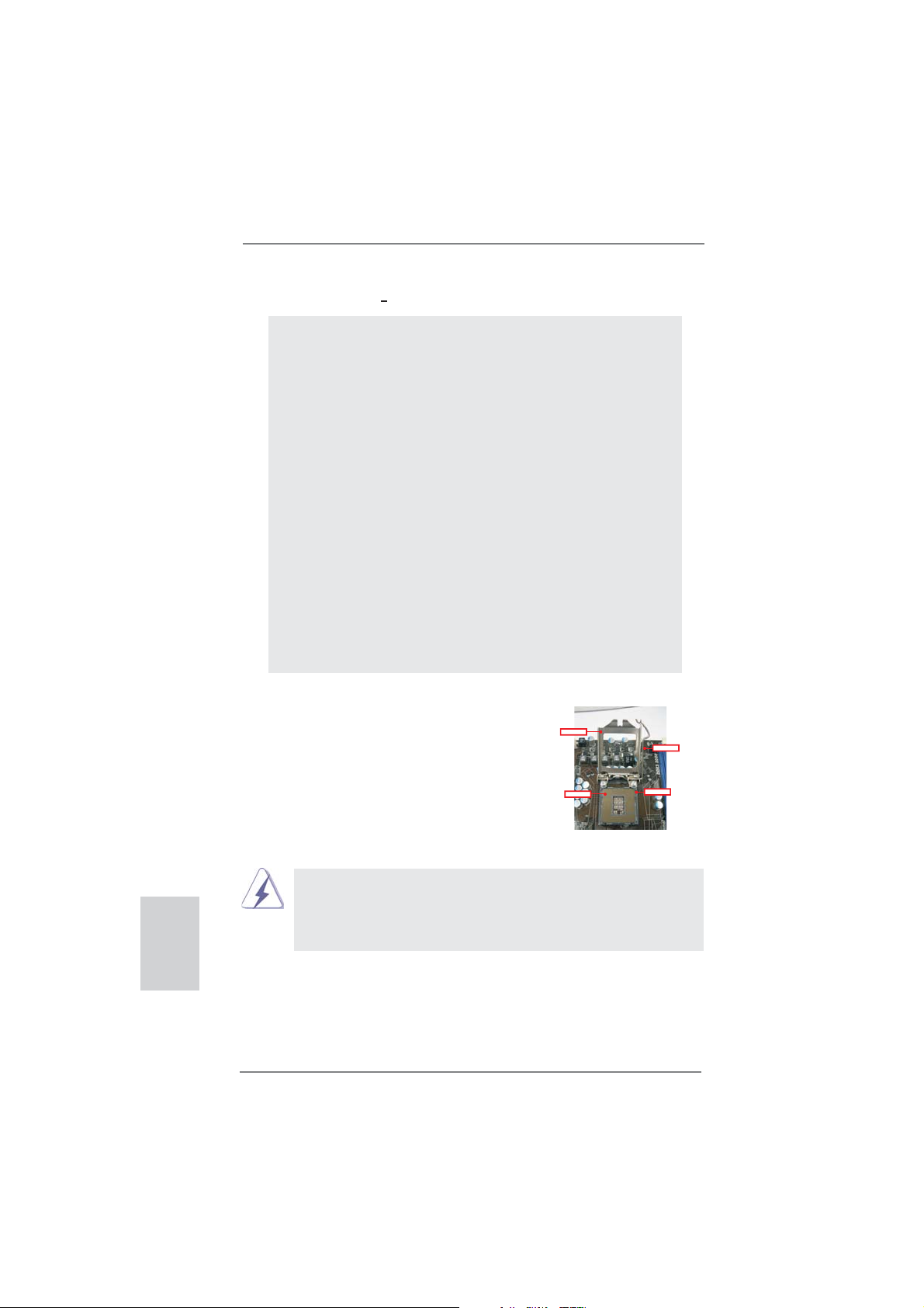
2.1 CPU Installation
For the installation of Intel 1155-Pin CPU,
please follow the steps below.
LoadPlate
LoadLever
English
10
ContactArray
1155-Pin Socket Overview
Before you insert the 1155-Pin CPU into the socket, please check if the
CPU surface is unclean or if there is any bent pin on the socket. Do not
force to insert the CPU into the socket if above situation is found. Otherwise, the CPU will be seriously damaged.
SocketBody
ASRock P65iCafe Motherboard
Page 11
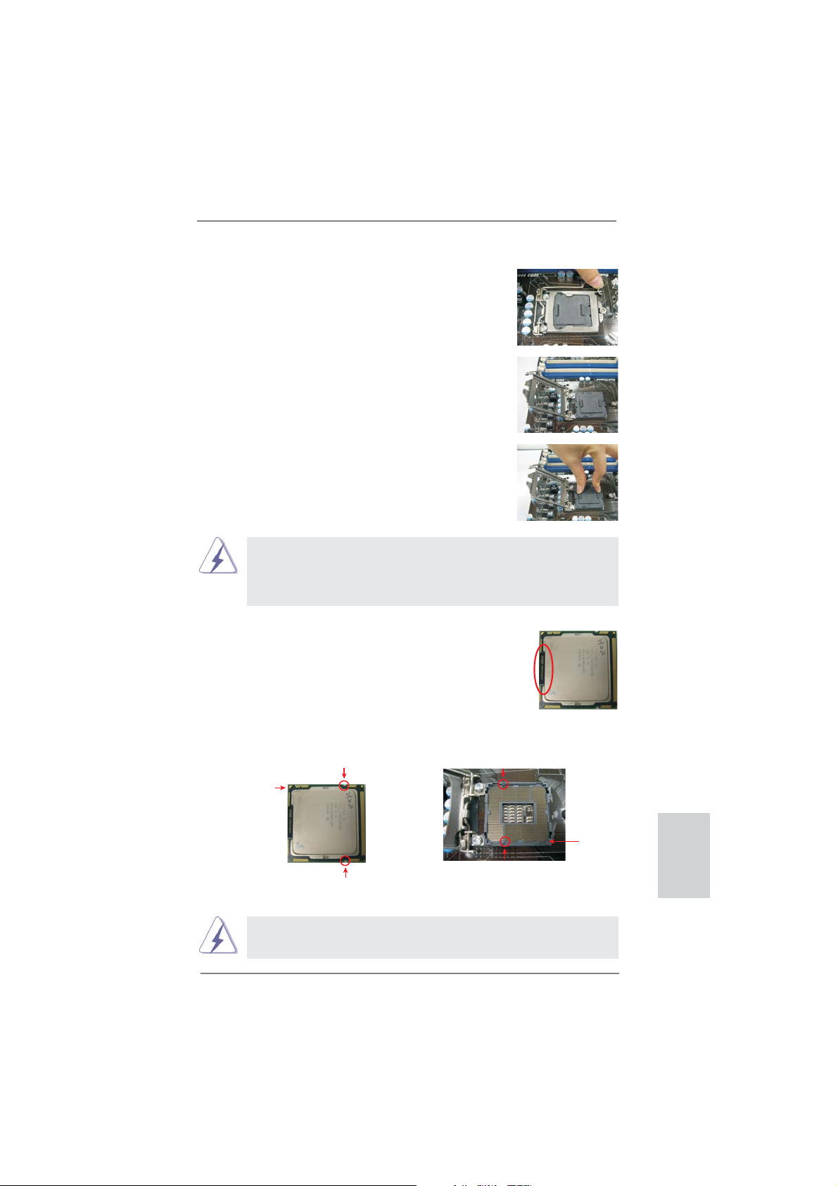
Step 1. Open the socket:
Step 1-1. Disengaging the lever by depressing
down and out on the hook to clear
retention tab.
Step 1-2. Rotate the load lever to fully open po-
sition at approximately 135 degrees.
Step 1-3. Rotate the load plate to fully open po-
sition at approximately 100 degrees.
Step 2. Remove PnP Cap (Pick and Place Cap).
1. It is recommended to use the cap tab to handle and avoid kicking
off the PnP cap.
2. This cap must be placed if returning the motherboard for after
service.
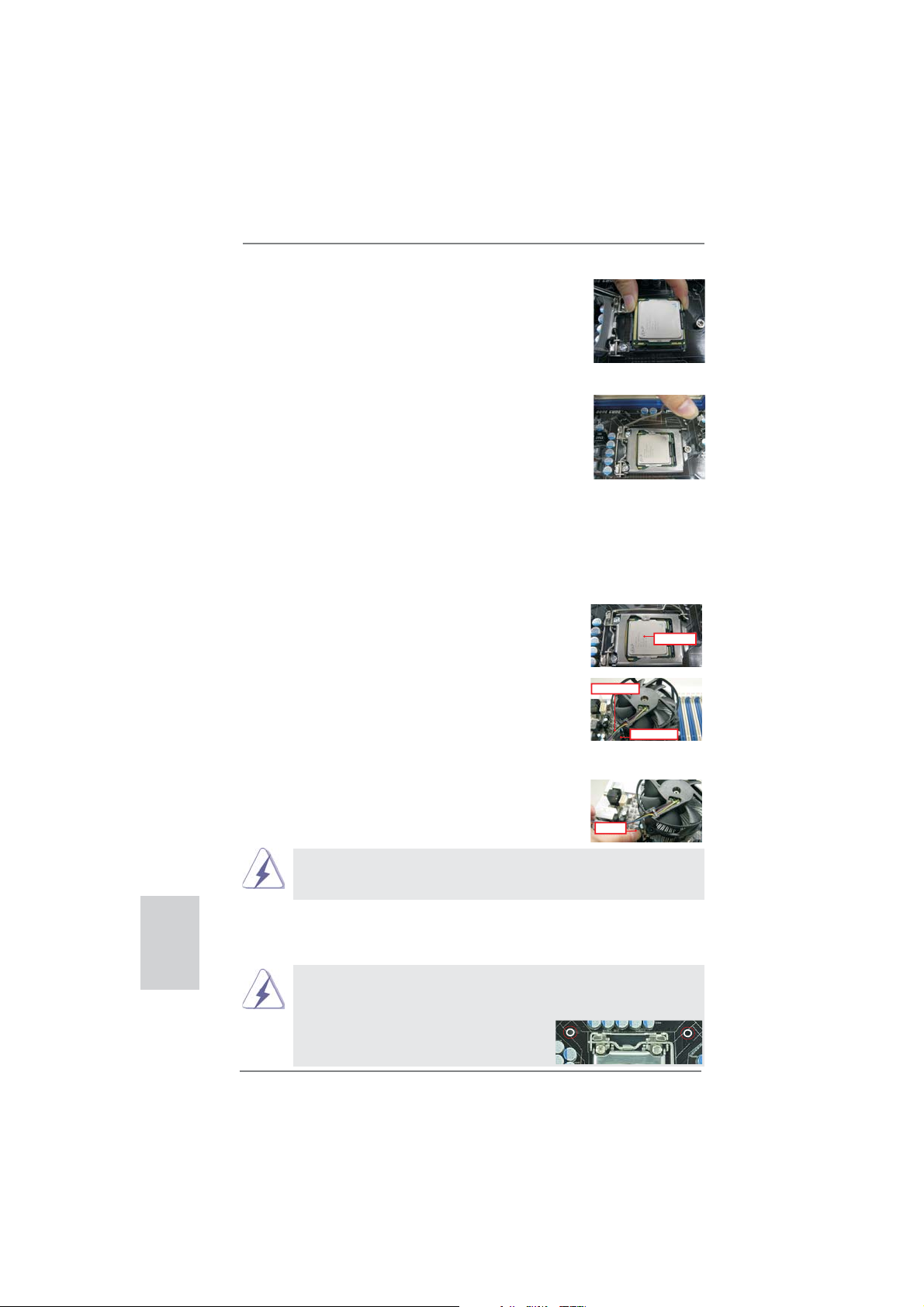
Step 3. Insert the 1155-Pin CPU:
Step 3-1. Hold the CPU by the edges where
are marked with black lines.
black line
Step 3-2. Orient the CPU with IHS (Integrated
Heat Sink) up. Locate Pin1 and the
two orientation key notches.
orientation key notch
Pin1
orientation key notch
1155-Pin CPU
For proper inserting, please ensure to match the two orientation key
notches of the CPU with the two alignment keys of the socket.
alignment key
1155-Pin Socket
ASRock P65iCafe Motherboard
alignment key
Pin1
English
11
Page 12
Step 3-3. Carefully place the CPU into the
socket by using a purely vertical motion.
Step 3-4. Verify that the CPU is within the sock-
et and properly mated to the orient
keys.
Step 4. Close the socket:
Step 4-1. Rotate the load plate onto the IHS.
Step 4-2. While pressing down lightly on load
plate, engage the load lever.
2.2 Installation of CPU Fan and Heatsink
For proper installation, please kindly refer to the instruction manuals of your CPU
fan and heatsink.
Below is an example to illustrate the installation of the heatsink for 1155-Pin CPU.
Step 1. Apply thermal interface material onto center of
IHS on the socket surface.
ApplyThermal
InterfaceMaterial
English
Step 2. Place the heatsink onto the socket. Ensure
fan cables are oriented on side closest to the
Fancables on side
closestto MB header
CPU fan connector on the motherboard (CPU_
FAN1, see page 2, No. 2).
Step 3. Align fasteners with the motherboard through-
holes.
Step 4. Rotate the fastener clockwise, then press
down on fastener caps with thumb to install
PressDown
and lock. Repeat with remaining fasteners.
If you press down the fasteners without rotating them clockwise, the
heatsink cannot be secured on the motherboard.
(4Places)
Step 5. Connect fan header with the CPU fan connector on the motherboard.
Step 6. Secure excess cable with tie-wrap to ensure cable does not interfere with
fan operation or contact other components.
Please be noticed that this motherboard supports Combo Cooler
Option (C.C.O.), which provides the fl exible option to adopt three dif-
ferent CPU cooler types, Socket LGA 775, LGA 1155 and LGA 1156.
The white throughholes are for Socket LGA
1155/1156 CPU fan.
12
ASRock P65iCafe Motherboard
Fastenerslots
pointingstraight out
Page 13
2.3 Installation of Memory Modules (DIMM)
This motherboard provides four 240-pin DDR3 (Double Data Rate 3) DIMM
slots, and supports Dual Channel Memory Technology. For dual channel confi guration, you always need to install identical (the same brand, speed, size
and chip-type) DDR3 DIMM pair in the slots of the same color. In other words,
you have to install identical DDR3 DIMM pair in Dual Channel (DDR3_A1 and
DDR3_B1; Blue slots; see p.2 No.5), so that Dual Channel Memory Technology
can be activated. This motherboard also allows you to install four DDR3 DIMMs
for dual channel confi guration, and please install identical DDR3 DIMMs in all
four slots. You may refer to the Dual Channel Memory Confi guration Table be-
low.
Dual Channel Memory Confi gurations
DDR3_A1 DDR3_A2 DDR3_B1 DDR3_B2
(Blue Slot) (White Slot) (Blue Slot) (White Slot)
(1) Populated - Populated (2)* Populated Populated Populated Populated
For the confi guration (2), please install identical DDR3 DIMMs in all four
*
slots.
1. If you want to install two memory modules, for optimal compatibility
and reliability, it is recommended to install them in the blue slots
(DDR3_A1 and DDR3_B1).
2. If a pair of memory modules is NOT installed in the same Dual
Channel, for example, installing a pair of memory modules in
DDR3_A1 and DDR3_A2, it is unable to activate the Dual Channel
Memory T echnology.
3. It is not allowed to install a DDR or DDR2 memory module into
DDR3 slot; otherwise, this motherboard and DIMM may be damaged.
4. Some DDR3 1GB double-sided DIMMs with 16 chips may not work
on this motherboard. It is not recommended to install them on this
motherboard.
5. If you install four single-sided DIMMs on this motherboard, they will
run at DDR3 1066 only.
6.
Due to chipset limitation, if you plan to install three or four memory
modules on this motherboard, please install only single-sided
memory modules.
7. This motherboard supports two double-sided or four single-sided
DIMMs. Therefore, if you install four DDR3 DIMMs, you can only
adopt four single-sided DIMMs.
English
ASRock P65iCafe Motherboard
13
Page 14
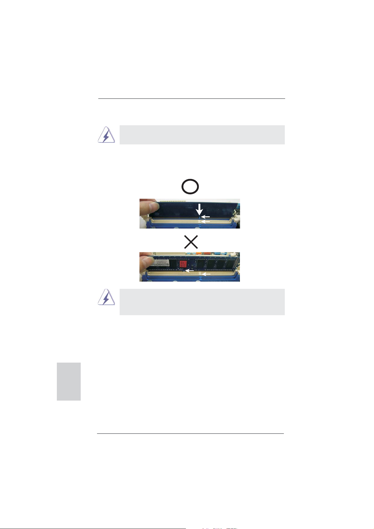
Installing a DIMM
Please make sure to disconnect power supply before adding or
removing DIMMs or the system components.
Step 1. Unlock a DIMM slot by pressing the retaining clips outward.
Step 2. Align a DIMM on the slot such that the notch on the DIMM matches the
break on the slot.
notch
break
notch
break
The DIMM only fi ts in one correct orientation. It will cause permanent
damage to the motherboard and the DIMM if you force the DIMM into
the slot at incorrect orientation.
English
Step 3. Firmly insert the DIMM into the slot until the retaining clips at both ends
fully snap back in place and the DIMM is properly seated.
14
ASRock P65iCafe Motherboard
Page 15
2.4 Expansion Slots (PCI and PCI Express Slots)
There are 2 PCI slot and 3 PCI Express slots on this motherboard.
PCI slots: PCI slots are used to install expansion cards that have the 32-bit PCI
interface.
PCIE slots:
PCIE1 (PCIE 3.0 x16 slot; Blue) is used for PCI Express x16 lane width
graphics cards.
PCIE2 / PCIE3 (PCIE 2.0 x1 slot; White) is used for PCI Express cards
with x1 lane width cards, such as Gigabit LAN card, SATA2 card, etc.
Only PCIE1 slot supports Gen 3 speed. To run the PCI Express in Gen
3 speed, please install an Ivy Bridge CPU. If you install a Sandy Bridge
CPU, the PCI Express will run only at PCI Express Gen 2 speed.
Installing an expansion card
Step 1. Before installing the expansion card, please make sure that the power
supply is switched off or the power cord is unplugged. Please read the
documentation of the expansion card and make necessary hardware
settings for the card before you start the installation.
Step 2. Remove the system unit cover (if your motherboard is already installed
in a chassis).
Step 3. Remove the bracket facing the slot that you intend to use. Keep the
screws for later use.
Step 4. Align the card connector with the slot and press fi rmly until the card is
completely seated on the slot.
Step 5. Fasten the card to the chassis with screws.
Step 6. Replace the system cover.
English
ASRock P65iCafe Motherboard
15
Page 16

2.5 Jumpers Setup
The illustration shows how jumpers are
setup. When the jumper cap is placed on
pins, the jumper is “Short”. If no jumper cap
is placed on pins, the jumper is “Open”. The
illustration shows a 3-pin jumper whose
pin1 and pin2 are “Short” when jumper cap
is placed on these 2 pins.
Jumper Setting Description
Clear CMOS Jumper
(CLRCMOS1)
(see p.2, No. 10)
Note: CLRCMOS1 allows you to clear the data in CMOS. To clear and reset the
system parameters to default setup, please turn off the computer and unplug
the power cord from the power supply. After waiting for 15 seconds, use a
jumper cap to short pin2 and pin3 on CLRCMOS1 for 5 seconds. However,
please do not clear the CMOS right after you update the BIOS. If you need
to clear the CMOS when you just fi nish updating the BIOS, you must boot
up the system fi rst, and then shut it down before you do the clear-CMOS ac-
tion. Please be noted that the password, date, time, user default profi le, 1394
GUID and MAC address will be cleared only if the CMOS battery is removed.
Clear CMOSDefault
English
16
ASRock P65iCafe Motherboard
Page 17

2.6 Onboard Headers and Connectors
Onboard headers and connectors are NOT jumpers. Do NOT place
jumper caps over these headers and connectors. Placing jumper caps
over the headers and connectors will cause permanent damage of the
motherboard!
Serial ATAII Connectors These four Serial ATAII
(SATA_0: see p.2, No. 12)
(SATA_1: see p.2, No. 20)
(SATA_2: see p.2, No. 13)
(SATA_3: see p.2, No. 18)
(SATAII) connectors support
SATA_0
SATA data cables for internal
storage devices. The current
SATAII interface allows up to
SATA_1
SATA_2
SATA_3
3.0 Gb/s data transfer rate.
Serial ATA3 Connectors These two Serial ATA3 (SATA3)
(SATA3_1: see p.2, No. 14)
(SATA3_2: see p.2, No. 15)
connectors support SATA data
cables for internal storage
SATA3_1
SATA3_2
devices. The current SATA3
interface allows up to 6.0 Gb/s
data transfer rate.
Serial ATA (SATA) Either end of the SATA data
Data Cable cable can be connected to the
(Optional)
SATA / SATAII / SATA3 hard
disk or the SATAII / SATA3
connector on this motherboard.
USB 2.0 Headers Besides six default USB 2.0
(9-pin USB6_7)
(see p.2 No. 22)
ports on the I/O panel, there
are two USB 2.0 headers on
this motherboard. Each
USB 2.0 header can support
two USB 2.0 ports.
(9-pin USB8_9)
(see p.2 No. 21)
Infrared Module Header This header supports an
(5-pin IR1)
optional wireless transmitting
(see p.2 No. 23)
and receiving infrared module.
1
USB_PWR
P-9
P-8
USB_PWR
1
IRTX
P+9
P+8
IRRX
GND
GND
+5VSB
GND
DUMMY
DUMMY
ASRock P65iCafe Motherboard
English
17
Page 18

Front Panel Audio Header This is an interface for front
(9-pin HD_AUDIO1)
(see p.2 No. 28)
panel audio cable that allows
convenient connection and
control of audio devices.
1
GND
PRESENCE#
MIC2_R
MIC2_L
MIC_RET
J_SENSE
OUT2_R
OUT_RET
OUT2_L
1. High Defi nition Audio supports Jack Sensing, but the panel wire on
the chassis must support HDA to function correctly. Please follow the
instruction in our manual and chassis manual to install your system.
2. If you use AC’97 audio panel, please install it to the front panel audio
header as below:
A. Connect Mic_IN (MIC) to MIC2_L.
B. Connect Audio_R (RIN) to OUT2_R and Audio_L (LIN) to OUT2_L.
C. Connect Ground (GND) to Ground (GND).
D. MIC_RET and OUT_RET are for HD audio panel only. You don’t
need to connect them for AC’97 audio panel.
E. To activate the front mic.
For Windows
Select “Mixer”. Select “Recorder”. Then click “FrontMic”.
For Windows
®
XP / XP 64-bit OS:
®
7 / 7 64-bit / VistaTM / VistaTM 64-bit OS:
Go to the "FrontMic" Tab in the Realtek Control panel. Adjust
“Recording Volume”.
System Panel Header This header accommodates
(9-pin PANEL1)
(see p.2 No. 16)
several system front panel
functions.
English
Connect the power switch, reset switch and system status indicator on the
chassis to this header according to the pin assignments below. Note the
positive and negative pins before connecting the cables.
PWRBTN (Power Switch):
Connect to the power switch on the chassis front panel. You may confi gure
the way to turn off your system using the power switch.
RESET (Reset Switch):
Connect to the reset switch on the chassis front panel. Press the reset
switch to restart the computer if the computer freezes and fails to perform a
normal restart.
PLED (System Power LED):
Connect to the power status indicator on the chassis front panel. The LED
is on when the system is operating. The LED keeps blinking when the sys-
tem is in S1 sleep state. The LED is off when the system is in S3/S4 sleep
state or powered off (S5).
18
ASRock P65iCafe Motherboard
Page 19

HDLED (Hard Drive Activity LED):
Connect to the hard drive activity LED on the chassis front panel. The LED
is on when the hard drive is reading or writing data.
The front panel design may differ by chassis. A front panel module mainly
consists of power switch, reset switch, power LED, hard drive activity LED,
speaker and etc. When connecting your chassis front panel module to this
header, make sure the wire assignments and the pin assign-ments are
matched correctly.
Chassis Speaker Header Please connect the chassis
(4-pin SPEAKER 1)
(see p.2 No. 19)
speaker to this header.
Chassis and Power Fan Connectors Please connect the fan cables
(4-pin CHA_FAN1)
(see p.2 No. 17)
ground pin.
(3-pin CHA_FAN2)
(see p.2 No. 8)
(3-pin CHA_FAN3)
(see p.2 No. 31)
to the fan connectors and
match the black wire to the
FAN_SPEED_CONTROL
CHA_FAN_SPEED
GND
+12V
CHA_FAN_SPEED
+12V
GND
(3-pin PWR_FAN1)
(see p.2 No. 32)
CPU Fan Connectors Please connect the CPU fan
(4-pin CPU_FAN1)
(see p.2 No. 2)
cable to the connector and
match the black wire to the
ground pin.
PWR_FAN_SPEED
+12V
GND
FAN_SPEED_CONTROL
CPU_FAN_SPEED
+12V
GND
1 2 3 4
Though this motherboard provides 4-Pin CPU fan (Quiet Fan) support, the 3-Pin
CPU fan still can work successfully even without the fan speed control function.
If you plan to connect the 3-Pin CPU fan to the CPU fan connector on this
motherboard, please connect it to Pin 1-3.
Pin 1-3 Connected
3-Pin Fan Installation
(3-pin CPU_FAN2)
(see p.2 No. 3)
GND
+12V
CPU_FAN_SPEED
ASRock P65iCafe Motherboard
English
19
Page 20

ATX Power Connector Please connect an ATX power
(24-pin ATXPWR1)
(see p.2 No. 7)
supply to this connector.
Though this motherboard provides 24-pin ATX power connector,
12 124
13
12
it can still work if you adopt a traditional 20-pin ATX power supply.
To use the 20-pin ATX power supply, please plug your
power supply along with Pin 1 and Pin 13.
24
English
20-Pin ATX Power Supply Installation
ATX 12V Power Connector Please connect an ATX 12V
(8-pin ATX12V1)
(see p.2 No. 4)
power supply to this connector.
8 5
4 1
1
13
Though this motherboard provides 8-pin ATX 12V power connector, it can still work
if you adopt a traditional 4-pin ATX 12V power supply. To use the 4-pin ATX power
supply, please plug your power supply along with Pin 1 and Pin 5.
8 5
4-Pin ATX 12V Power Supply Installation
4 1
Serial port Header This COM1 header supports a
(9-pin COM1)
(see p.2 No. 24)
serial port module.
HDMI_SPDIF Header HDMI_SPDIF header, providing
(2-pin HDMI_SPDIF1)
(see p.2 No. 29)
SPDIF audio output to HDMI
VGA card, allows the system to
connect HDMI Digital TV/
projector/LCD devices. Please
connect the HDMI_SPDIF
connector of HDMI VGA card to
this header.
20
ASRock P65iCafe Motherboard
Page 21

2.7 Driver Installation Guide
To install the drivers to your system, please insert the support CD to your optical
drive fi rst. Then, the drivers compatible to your system can be auto-detected and
listed on the support CD driver page. Please follow the order from up to bottom side
to install those required drivers. Therefore, the drivers you install can work properly.
2.8 Installing Windows® 7 / 7 64-bit / Vista
TM
/ Vista
TM
64-bit / XP
/ XP 64-bit Without RAID Functions
If you want to install Windows® 7 / 7 64-bit / VistaTM / VistaTM 64-bit / XP / XP 64bit OS on your SATA / SATAII / SATA3 HDDs without RAID functions, please follow
below procedures according to the OS you install.
2.8.1 Installing Windows® XP / XP 64-bit Without RAID
Functions
If you want to install Windows® XP / XP 64-bit OS on your SATA / SATAII / SATA3
HDDs without RAID functions, please follow below steps.
Using SATA / SATAII / SATA3 HDDs with NCQ function
STEP 1: Set Up UEFI.
A. Enter UEFI SETUP UTILITY Advanced screen SATA Confi guration.
B. Set the option “SATA Mode Selection” to [AHCI] for SATA2 ports.
Set the option “ASMedia SATA3 Mode” to [AHCI] for SATA3 ports.
STEP 2: Make a SATA / SATAII / SATA3 driver diskette. (Please use USB fl oppy
or fl oppy disk.)
A. Insert the Support CD into your optical drive to boot your system.
B. During POST at the beginning of system boot-up, press <F11> key, and then a
window for boot devices selection appears. Please select CD-ROM as the boot
device.
C. When you see the message on the screen, “Do you want to generate Serial
ATA driver diskette [YN]?”, press <Y>.
D. Then you will see these messages,
Please insert a diskette into the fl oppy drive.
WARNING! Formatting the fl oppy diskette will
lose ALL data in it!
Start to format and copy fi les [YN]?
Please insert a fl oppy diskette into the fl oppy drive, and press <Y>.
E. The system will start to format the fl oppy diskette and copy SATA / SATAII /
SATA3 drivers into the fl oppy diskette.
English
ASRock P65iCafe Motherboard
21
Page 22

STEP 3: Install Windows® XP / XP 64-bit OS on your system.
After making a SATA / SATAII / SATA3 driver diskette, you can start to install Windows® XP / XP 64-bit on your system. At the beginning of Windows® setup, press
F6 to install a third-party AHCI driver. When prompted, insert the SATA / SATAII /
®
SATA3 driver diskette containing the Intel
AHCI driver. After reading the fl oppy disk,
the driver will be presented. Select the driver to install according to the mode you
choose and the OS you install.
Using SATA / SATAII / SATA3 HDDs without NCQ function
STEP 1: Set up UEFI.
A. Enter UEFI SETUP UTILITY Advanced screen SATA Confi guration.
B. Set the option “SATA Mode Selection” to [IDE] for SATA2 ports.
Set the option “ASMedia SATA3 Mode” to [IDE] for SATA3 ports.
STEP 2: Install Windows
®
XP / XP 64-bit OS on your system.
English
2.8.2 Installing Windows® 7 / 7 64-bit / Vista
TM
/ Vista
TM
64-bit
Without RAID Functions
If you want to install Windows® 7 / 7 64-bit / VistaTM / VistaTM 64-bit OS on your SATA
/ SATAII / SATA3 HDDs without RAID functions, please follow below steps.
Using SATA / SATAII / SATA3 HDDs with NCQ function
STEP 1: Set Up UEFI.
A. Enter UEFI SETUP UTILITY Advanced screen SATA Confi guration.
B. Set the option “SATA Mode Selection” to [AHCI] for SATA2 ports.
Set the option “ASMedia SATA3 Mode” to [AHCI] for SATA3 ports.
STEP 2: Install Windows
system.
Using SATA / SATAII / STA3 HDDs without NCQ function
STEP 1: Set up UEFI.
A. Enter UEFI SETUP UTILITY Advanced screen SATA Confi guration.
B. Set the option “SATA Mode Selection” to [IDE] for SATA2 ports.
Set the option “ASMedia SATA3 Mode” to [IDE] for SATA3 ports.
STEP 2: Install Windows
system.
®
7 / 7 64-bit / VistaTM / VistaTM 64-bit OS on your
®
7 / 7 64-bit / VistaTM / VistaTM 64-bit OS on your
22
ASRock P65iCafe Motherboard
Page 23

3. BIOS Information
The Flash Memory on the motherboard stores BIOS Setup Utility. When you start up
the computer, please press <F2> or <Del> during the Power-On-Self-Test (POST)
to enter BIOS Setup utility; otherwise, POST continues with its test routines. If you
wish to enter BIOS Setup after POST, please restart the system by pressing <Ctl>
+ <Alt> + <Delete>, or pressing the reset button on the system chassis. The BIOS
Setup program is designed to be user-friendly. It is a menu-driven program, which
allows you to scroll through its various sub-menus and to select among the predetermined choices. For the detailed information about BIOS Setup, please refer to the
User Manual (PDF fi le) contained in the Support CD.
4. Software Support CD information
®
This motherboard supports various Microsoft
64-bit / VistaTM / Vista
motherboard contains necessary drivers and useful utilities that will enhance motherboard features. To begin using the Support CD, insert the CD into your CD-ROM
drive. It will display the Main Menu automatically if “AUTORUN” is enabled in your
computer. If the Main Menu does not appear automatically, locate and double-click
on the fi le “ASSETUP.EXE” from the BIN folder in the Support CD to display the
menus.
TM
64-bit / XP / XP 64-bit. The Support CD that came with the
Windows® operating systems: 7 / 7
ASRock P65iCafe Motherboard
English
23
Page 24

1. 제품소개
ASRock은사용자에게 알립니다
ASRock 의
인보드는 엄격한 품질관리 하에 생산되어진 신뢰성 있는 메인보드 입니다 . 이 제품
은 고 품격 디자인과 함께 ASRock 의 우수한 품질과 최고의 안정성을 자랑하고 있습
니다 . 이 빠른 설치 안내서에는 마더보드에 대한 설명과 단계별 설치 방법이 실려 있
습니다 . 마더보드에 대한 보다 자세한 내용은 지원 CD 의 사용 설명서에서 확인할 수
있습니다 .
메인보드의 사양이나 바이오스가 업 데이트 되기 때문에 이 사용자
설명서의 내용은 예고 없이 변경되거나 바뀔 수가 있습니다 . 만일을
생각해서 이 사용자 설명서의 어떤 변경이 있으면 ASRock 의 웹
사이트에서 언제든지 업 데이트를 하실 수 있습니다 . 웹사
이트에서 최신 VGA 카드와 CPU 지원 목록을 확인할 수 있습니다 .
ASRock 의 웹사이트 주소는 http://www.asrock.com 입니다 .
본 머더보드와 관련하여 기술 지원이 필요한 경우 당사 웹 사이트를 방문하
여 사용 중인 모델에 대한 특정 정보를 얻으십시오 .
1.1 패키지 내용
ASRock
(ATX 폼 팩터 : 12.0” x 8.6”, 30.5 x 21.8 cm)
ASRock
ASRock
시리얼 ATA (SATA) 데이터 케이블 2 개 ( 선택 사양 )
I/O 차폐 1 개
P65iCafe
www.asrock.com/support/index.asp
P65iCafe
P65iCafe
P65iCafe
메인 보드를 구매하여 주신것에 대하여 감사 드립니다 . 이 메
마더보드
퀵 설치 가이드
지원 CD
ASRock은사용자에게 알립니다
Windows
위해서 Storage Configuration(스토리지 구성)에서 BIOS 옵션을 AHCI
모드로 설정하는 것이 좋습니다. BIOS 설정과 관련하여 자세한 내용은 지
원 CD에 포함된 “사용 설명서”를 참조하십시오.
한 국 어
24
®
7 / 7 64-비트 / Vista
...
TM
/ VistaTM 64-비트의 성능을 향상시키기
ASRock P65iCafe Motherboard
Page 25

1.2 설명서
플랫폼 - ATX 폼 팩터 : 12.0” x 8.6”, 30.5 x 21.8 cm
- 완전 고체 축전지 디자인
CPU - LGA1155 패키지에서 3 세대 및 2 세대 Intel
i3 을 지원합니다
- 4 + 1 전원 위상 디자인
- Intel
®
Turbo Boost 2.0 기술 지원
- K- 시리즈 잠금 해제 CPU 지원
- 하이퍼 - 스레딩 기술 지원 ( 주의 1 참조 )
칩셋 - Intel
®
H61
- Intel® Rapid Start 기술과 Smart Connect 기술을 지원합니다
메모리 - 듀얼 채널 메모리 기술 지원 ( 주의 2 참조 )
- DDR3 DIMM 슬롯 4 개
- DDR3 1600/1333/1066 비 -ECC, 언버퍼드 메모리를 지원
(Intel
®
Ivy Bridge CPU 를 탑재한 DDR3 1600, Intel® Sandy
Bridge CPU 를 탑재한 DDR3 1333)
- 최대 시스템 메모리 용량 : 16GB ( 주의 3 참조 )
- Intel
®
Ivy Bridge CPU 에서 Intel® 익스트림 메모리 프로파일
(XMP)1.3/1.2 지원
확장 슬롯 - PCI Express 3.0 x16 슬롯 (x16 모드의 경우 파란색 ) 1 개
* PCIE 3.0 은 Intel® Ivy Bridge CPU 에서만 지원됩니다 .
Intel® Sandy Bridge CPU 는 PCIE 2.0 만 지원합니다 .
- PCI Express 2.0 x1 슬롯 2 개
- 의 PCI 슬롯 2 개
오디오 - 7.1 CH HD Audio (Realtek ALC887 Audio Codec)
- THX TruStudio
TM
지원
랜 - PCIE x1 Gigabit LAN 10/100/1000 Mb/s
- Realtek RTL8111E
- 웨이크-온-랜 지원
- LAN 케이블 감지 지원
- 절전형 이더넷 802.3az 지원
- PXE 지원
후면판 I/O I/O Panel
- 1 개 PS/2 키보드 포트
- 1 개광학 SPDIF 출력 포트
- 6 개디폴트 USB 2.0 포트
- 1 개 LED(ACT/LINK LED 및 SPEED LED) 가 있는 RJ-45
LAN 포트
- 오디오 잭 : 후방 스피커 / 중앙 / 저음 / 라인 인 / 전방 스피커 /
마이크 ( 주의 4 참조 )
®
CoreTM i7 / i5 /
한 국 어
ASRock P65iCafe Motherboard
25
Page 26

한 국 어
SATA3 - ASMedia ASM1061 SATA3 6.0Gb/s 커넥터 2 개 , 하드웨어
NCQ, AHCI 및 “Hot Plug” ( 핫플러그 ) 기능 지원
온보드 헤더 - 4 개 의 SATA2 3.0Gb/s 커넥터 , NCQ, AHCI 및“핫 플러그”
및 커넥터 기 능 지원
- 2 개 의 SATA3 6.0Gb/s 커넥터
- 적외선 모듈 헤더 1 개
- COM 포트 헤더 1 개
- HDMI_SPDIF 헤더 1 개
- CPU/ 섀시 / 전원 팬 커넥터
- 24 핀 ATX 전원 헤더
- 8 핀 ATX 12V 파워 콘넥터
- 전면부 오디오 콘넥터
- USB 2.0 헤더 2 개 (4 개의 추가 USB 2.0 포트를 지원하는 헤더
2 개 )
BIOS - 32Mb AMI BIOS
- GUI 지원을 제공하는 AMI UEFI 적합형 BIOS
- “플러그 앤 플레이” 지원
- ACPI 1.1 웨이크 - 업 이벤트와의 호환
- 점퍼 프리 지원
- SMBIOS 2.3.1 지원
- IGPU, DRAM, PCH, CPU PLL, VTT, VCCSA 전압 멀티
조절
지원 CD - 드라이버 , 유틸리티 , 백신 소프트웨어 ( 시험판 ), CyberLink
MediaEspresso 6.5 평가판 , ASRock MAGIX Multimedia
Suite - OEM
특점및 특성 - ASRock Extreme Tuning Utility (AXTU) ( 주의 5 참조 )
- ASRock Instant Boot
- ASRock Instant Flash ( 주의 6 참조 )
- ASRock APP Charger ( 주의 7 참조 )
- ASRock SmartView ( 주의 8 참조 )
- ASRock XFast USB ( 주의 9 참조 )
- ASRock XFast LAN ( 주의 10 참조 )
- ASRock XFast RAM ( 주의 11 참조 )
- ASRock On/Off Play 기술 ( 주의 12 참조 )
- 하이드브리 부스터 :
- ASRock U-COP ( 주의 13 참조 )
- B.F.G..(Boot Failure Guard)
- 콤보 쿨러 옵션 (C.C.O.) ( 주의 14 참조 )
- 굿나잇 LED
26
ASRock P65iCafe Motherboard
Page 27

하드웨어 모니터 - CPU 온도 감지
- 마더보드 온도 감지
- CPU/ 섀시 / 전원 팬 회전 속도계 : 샤시 ( 케이스 ) 팬 회전 속
도계
- CPU/ 섀시 저소음 팬 (CPU 온도에 의한 섀시 팬속도 자동 조정
가능 )
- CPU/ 섀시팬 멀티스피드 컨트롤
- 전압 감시 기능 : +12V,+5V,+3.3V,Vcore
OS - 마이크로 소프트 Windows
Vista
TM
64 비트 / XP/XP 64 비트 와 호환
®
7/7 64 비트 /VistaTM/
인증서 - FCC, CE, WHQL
- ErP/EuP 지원 (ErP/EuP 지원 전원 공급기가 요구됨 )
( 주의 15 참조 )
* 상세한 제품정보는 당사의 웹사이트를 방문할수있습니다 . http://www.asrock.com
경고
오버클로킹에는 BIOS 설정을 조정하거나 Untied Overclocking Technology 를 적
용하거나타업체의 오버클로킹 도구를 사용하는 것을 포함하여 어느 정도의 위험이
따른다는 것을 유념하십시오 . 오버클로킹은 시스템 안정성에 영향을 주거나 심지어
시스템의 구성 요소와 장치에 손상을 입힐지도 모릅니다 . 오버클로킹은 사용자 스스
로 위험과 비용을 감수하고 해야 합니다 . 당사는 오버클로킹에 의해 발생할 수 있는
손상에 대해서 책임이 없습니다 .
주의 !
1. 하이퍼 - 스레딩 기술의 셋팅에 대하여는 지원 CD 의 사용자 매뉴얼의 38 페
이지를참고하세요 .
2. 이 마더보드는 듀얼 채널 메모리 기술을 지원합니다 . 듀얼 채널 메모리 기술
을구현하기 전에 올바른 설치를 위하여 13 쪽에 있는 메모리 모듈 설치 안내
를읽으십시오 .
3. 운영 체제 한계 때문에 Windows
실제 메모리 크기는 4 GB 이하일 수 있습니다 . 64 비트 CPU 와 Windows
의 경우 그런 한계가 없습니다 . ASRock XFast RAM 을 사용하여 Windows
4. 본 마더보드는 마이크 입력에 대해서 스테레오와 모노 모드 둘 다 지
원합니다 . 본 마더보드는 오디오 출력에 대해서 2 채널 , 4 채널 , 6 채널
및 8 채널 모드를지원합니다 . 올바른 연결을 위해 3 쪽에 나온 표
를확인하십시오 .
5.
인터페이스로 다른 시스템 기능을 미세 조정하는 일체형 도구로서 ,
여기에는 하드웨어 모니터 , 팬 컨트롤 , 오버클로킹 , OC DNA, IES
등이 포함되어 있습니다 . 하드웨어 모니터는 시스템의 주요 값을 표
시합니다 . 팬 컨트롤은 조정하려는 팬 속도와 온도를 표시합니다 . 오
에서 사용할 수 없는 메모리를 이용할 수 있습니다 .
AXTU (ASRock Extreme Tuning Utility) 는 사용자에게 친숙한
®
7 / Vista™ / XP 에서 시스템 용도로 예약된
®
OS
®
한 국 어
ASRock P65iCafe Motherboard
27
Page 28

한 국 어
버클로킹에서는 CPU 주파수를 오버클로킹하여 최적의 시스템 성능
으로 조정할 수 있습니다 . OC DNA 에서는 OC 설정을 프로파일로
저장하고 이를 친구와 공유할 수 있습니다 . 그러면 친구가 OS 프
로파일을 자신의 시스템에 로드하여 동일한 OS 설정을 사용할 수 있
력위상의 수를 줄여 CPU 코어가 유휴 상태일 때 컴퓨터 성능을 저하
시키지 않으면서 효율을 높일 수 있습니다 . ASRock 의 AXTU
(Extreme Tuning Utility) 의 작동 절차는 당사의 웹 사이트를 참조하
십시오 . ASRock 웹 사이트 : http://www.asrock.com
6. ASRock Instant Flash 는 플래시 ROM 에 내장된 BIOS 유틸리티
입니다 . 이 편리한 BIOS 업데이트 툴을 사용하면 먼저 MS-DOS 나
Windows
데이트할 수 있습니다 . POST 중에 BIOS 셋업 메뉴에서 <F6> 키를
누르거나 <F2> 키를 누르면이 유틸리티로 ASRock Instant Flash 에
액세스할 수 있습니다 .. 이제 이 툴을 시작하여 USB 플래시 드라이
브 , 플로피 디스크 또는 하드 드라이브에 새 BIOS 파일을 저장하면
플로피 디스켓이나 기타 복잡한 플래시 유틸리티를추가로 준비하
지 않고도 몇 번의 클릭만으로도 BIOS 를 업데이트할 수 있습니다 .
USB 플래시 드라이브 또는 하드 드라이브는 FAT32/16/12 파일 시스
템을 사용해야 합니다 .
7. 아이폰 / 아이팟 터치 / 아이패드와 같은 Apple 기기들을 더 빠르고
덜제한된 방식으로 충전하려는 경우 , ASRock 이 제공하는 놀라운
솔루션인 ASRock APP Charger 를 이용하십시오 . APP Charger
드라이버를 설치하기만 하면 아이폰이 컴퓨터를 통해서 훨씬 더 빨리
충전되며 충전 속도도최대 40% 더 빨라집니다 . ASRock APP
Charger 는 많은 Apple 기기를 동시에 빨리 충전할 수 있게 하며 ,
PC 가 대기 모드 (S1), RAM 에 대한 일시 중단 (S3), 최대 절전 모
드 (S4) 또는 전원 꺼짐 모드 (S5) 에 들어갈 때도 연속적충전을 지원
합니다 . APP Charger 드라이버를 설치하면 그 어느 때보다 더간편
하고 빠르게 충전할 수 있습니다 . ASRock 웹사이트 : http://www.
asrock.com/Feature/AppCharger/index.asp
8.
트 , 사용자의 검색 기록 , 페이스북 친구 , 실시간 뉴스 피드를 더 개인적인 인
터넷 경험을 위한 향상된 보기로 결합하는 IE 용 스마트 시작 페이지입니다 .
ASRock 마더보드에만 친구들과 즉시 연락하도록 도와 주는 SmartView 유
틸리티가 탑재되어 있습니다 . SmartView 기능을 이용하려면 OS 버전이
Windows
IE8 인지 확인하십시오 . ASRock 웹사이트 : http://www.asrock.com/
Feature/SmartView/index.asp
습니다 . IES (Intelligent Energy Saver) 의 경우 , 전압 조절기로 출
®
같은 운영체제에 들어가지 않고도 시스템 BIOS 를 업
인터넷 브라우저의 새로운 기능인 SmartView 는 가장 많이 방문한 웹사이
®
7 / 7 64 비트 / VistaTM / VistaTM 64 비트이고 브라우저 버전이
9. ASRock XFast USB 는 USB 스토리지 장치 성능을 높여줍니다 . 성능은
장치의 속성에 따라 다를 수 있습니다 .
10. ASRock XFast LAN 은 더 빠른 인터넷 접속과 아래와 같은 이점을 제공
합니다 . LAN 응용 프로그램 우선순위 결정 : 응용 프로그램 우선순위를
이상적으로 구성할 수 있고 / 또는 새 프로그램을 추가할 수 있습니다 . 게
임 지연 시간 감소 : 온라인 게임 우선순위를 더 높게 설정한 후 게임 지연
28
ASRock P65iCafe Motherboard
Page 29

시간을 낮출 수 있습니다 . 트래픽 형성 : Youtube HD 비디오를 보면서 동
시에 파일을 다운로드할 수 있습니다 . 데이터의 실시간 분석 : 상태창에서
현재 어떤 데이터 스트림을 전송 중인지 쉽게 알 수 있습니다 .
11. ASRock XFast RAM 은 AXTU (ASRock Extreme Tuning Utility) 에 포함
된 새로운 기능입니다 . Windows
메모 리 공간을 사용합니다 . ASRock XFast RAM 은 이전에 방문했던 웹사이
트의로딩 시간을 단축하며 웹 서핑을 이전보다 더 빠르게 합니다 . 또한 Adobe
Photoshop 속도를 5 배 증가 시킵니다 . ASRock XFast RAM 의 또 다른 장점
은 SSD 또는 HDD 의 액세스 빈도를줄여 수명을 확장 늘입니다 .
12. ASRock On/Off Play 기술은 사용자가 MP3 플레이어 또는 휴대전화와
같은 이동식 오디오 장치에서 PC 에 이르는 여러 장치에서 고음질 오디오
경험을 즐길 수 있게 하며 PC 가 꺼져 있을 때도 ( 또는 ACPI S5 모드에 있
을 때도 ) 고음질 오디오 경험을 즐길 수 있게 합니다 . 또한 이 마더보드는
사용자에게 가장 편리한 컴퓨팅 환경을 제공하는 무료의 3.5 mm 오디오
케이블 ( 옵션 ) 을 제공합니다 .
13. 시스템을 다시 시작하기 전에 메인보드 위의 CPU 팬이 정상적으로
동작 또는 장착되어 있는지 확인하여 주십시오 . 고온 방지를 위하여
PC 시스템을 설치할 때 CPU 와 방열판사이에 그리스를 발라 주셔야
합니다 .
14. 콤보 쿨러 옵션 (C.C.O.) 은 3 개의 다른 CPU 쿨러 타입 , 소켓 LGA
775, LGA 1155 와 LGA 1156 을 채택할 수 있는 유연한 옵션을 제공
합니다 . 모든 775 와 1156 CPU 팬을 사용할 수 있는 겻은 아닙니다 .
15. EuP 는 Energy Using Product ( 에너지 사용 제품 ) 의 약어이며 유
럽 연합이 완제품 시스템의 전력 소비량을 정의하기 위해 제정한 표
준이었습니다 . EuP 에 따르면 , 완제품 시스템의 총 AC 전원은 끄
기 모드 상태에서 1.00W 미만이어야 합니다 . EuP 표준을 충족하려
면 EuP 지원 마더보드 및 EuP 지원 전원공급장치가 필요합니다 . 인
텔 (Intel) 의 제안에 따르면 EuP 지원 전원공급장치는 5V 대기 전력
효율이 100 mA 전류 소비 하에서 50% 보다 높아야 한다는 기준을 충
족해야 합니다 . EuP 지원 전원공급장치를 선택하려면 전원공급장치
제조업체에 자세한 사항을 문의하시기 바랍니다 .
®
OS 32-bit CPU 에서는 사용할 수 없는
ASRock P65iCafe Motherboard
한 국 어
29
Page 30

1.3 점퍼 셋팅
그림은 점퍼를 어떻게 셋업 하는지를 보여줍니다 .
점퍼 캡이 핀 위에 있을 때 , 점퍼는 “쇼트”입니다 .
점퍼 캡이 핀 위에 없을 때 점퍼는 “오픈” 입니다 .
그림은 3 개의 핀 중 1-2 번 핀이 “쇼트”임을
보여주는 것이며 , 점퍼 캡이 이 두 핀 위에 있음을
보여주는 것입니다 .
점퍼 세팅
CMOS 초기화
(CLRCMOS1, 3 핀 점퍼 )
(2 페이지 , 10 번 항목 참조 )
참고 : CLRCMOS1 을 사용하여 CMOS 에 들어 있는 데이터를 삭제할 수 있습니다 .
시스템 매개변수를 삭제하고 기본 설정으로 복원하려면 , 컴퓨터를 끄고 전원
공급장치에서 플러그를 뽑으십시오 . 15 초를 기다린 다음 점퍼 캡을 사용하여
CLRCMOS1 의 핀 2 와 핀 3 을 5 초 동안 단락하십시오 . 그러나 BIOS 업데이트
직후에는 CMOS 를 삭제하지 마십시오 . BIOS 를 업데이트하자마자 CMOS 를
삭제해야 하는 경우 먼저 시스템을 부팅하고 CMOS 를 종료하고 삭제 작업을 해
야 합니다 . CMOS 배터리를 제거할 경우에만 암호 , 날짜 , 시간 , 사용자 기본 프
로파일 , 1394 GUID, MAC 주소가 삭제됩니다 .
CMOS 삭제기본 설정
한 국 어
30
ASRock P65iCafe Motherboard
Page 31

1.4 온보드 헤더 및 커넥터
주의!
세요 . 커넥터에 점퍼 캡을 설치하면 마더보드가 영구적으로 손상됩니다 !
콘넥터 그림 설명
시리얼 ATAII 커넥터 4 개의 시리얼 ATAII
(SATA_0: 2 페이지 , 12 번 항목 참조 )
(SATA_1: 2 페이지 , 20 번 항목 참조 )
(SATA_2: 2 페이지 , 13 번 항목 참조 )
(SATA_3: 2 페이지 , 18 번 항목 참조 )
지원합니다 . 현재의 SATAII
인터페이스는 최고 3.0 Gb/s 의
데이터 전송 속도를
지원합니다 .
시리얼 ATA3 커넥터 2 개의 시리얼 ATA3
(SATA3_1: 2 페이지 , 14 번 항목 참조 )
(SATA3_2: 2 페이지 , 15 번 항목 참조 )
을지원합니다 . 커넥터가 내부
지원합니다 . 현재의 SATA3
인터페이스는 최고 6.0 Gb/s 의
데이터 전송 속도를
지원합니다 .
이 콘넥터는 점퍼가 아닙니다 . 이 콘넥터 위에 점퍼 캡을 사용하지마
SATA_0
(SATA) 커넥터는 내부 저장 장
SATA_2
치용 SATA 데이터 케이블을
지원합니다 . 커넥터가 내부
SATA_1
기억 장치용 SATA 케이블을
(SATA3) 커넥터는 내부 저장
장치용 SATA 데이터 케이블
SATA_3
SATA3_1
SATA3_2
기억 장치용 SATA 케이블을
시리얼 ATA(SATA)
데이터 케이블
( 선택 사양 )
SATA 데이터 케이블의 임의
적인 측을 마더보드의 SATA /
SATAII / SATA3 하드 디스크
혹은 SATAII / SATA3 커넥터
에 연결합니다 .
USB 2.0 헤더
(9 핀 USB6_7)
(2 페이지 , 22 번 항목 참조 )
본 머더보드에는 I/O 패널에 있
는 6 개의 기본 USB 2.0 포트
외에도 USB 2.0 헤더가 2 개 있
습니다 . 각각의 USB 2.0 헤더
는 2 개의 USB 2.0 포트를 지원
할 수 있습니다 .
(9 핀 USB8_9)
(2 페이지 , 21 번 항목 참조 )
1
USB_PWR
P-9
P-8
USB_PWR
P+9
P+8
GND
GND
DUMMY
ASRock P65iCafe Motherboard
한 국 어
31
Page 32

1
IRTX
1
IRRX
GND
MIC2_L
+5VSB
DUMMY
GND
PRESENCE#
MIC_RET
J_SENSE
OUT2_R
MIC2_R
OUT_RET
OUT2_L
적외선 모듈 헤더 이 헤더는 선택품목인 무선
(5 핀 IR1)
적외선 송수신 모듈을
(2 페이지 , 23 번 항목 참조 )
지원합니다 .
전면부 오디오 콘넥터 이 콘넥터는 오디오 장치를
(9 핀 HD_AUDIO1)
(2 페이지 , 28 번 항목 참조 )
편리하게 조절하고 연결할 수
있는 전면 오디오 인터페이스
입니다 .
1. High Definition Audio( 고음질 오디오 ) 는 잭 센스 기능을 지원하나 , 제
대로작동하려 면 섀시의 패널 와이어가 HAD 를 지원해야 합니다 . 이 설
명서 및 섀시 설명서의지침 을 따라 시스템을 설치하십시오 .
2. AC’97 오디오 패널을 사용하는 경우 , 이를 아래와 같이 프런트 패널
의 오디오헤 더에 설치하십시 오 .
A. Mic_IN (MIC) 을 MIC2_L 에 연결합니다 .
B. Audio_R (RIN) 을 OUT2_R 에 연결하고 , Audio_L (LIN)을
OUT2_L 에 연결합 니다 .
C. Ground (GND) 을 Ground (GND) 에 연결합니다 .
D. MIC_RET 및 OUT_RET 는 HD 오디오 패널 전용입니다 .
이들을 AC’97 오디오 패널에 연결 하지 않아도 됩니다 .
E. 앞면 마이크 작동 .
Windows
®
XP / XP 64 비트 OS 의 경우 :
“
Mixer” (믹서)와 “Recorder” ( 리코더 ) 를 선택한 후
“
FrontMic” ( 앞면 마이크 ) 를 선택합니다 .
Windows® 7 / 7 64 비트 / VistaTM / VistaTM 64 비트 OS 의
경우:
Realtek 제어판에서“FrontMic” ( 앞면 마이크 ) 로 가서
“
Recording Volume” ( 리코딩 볼륨 ) 을 조정합니다 .
한 국 어
32
시스템 콘넥터 이 콘넥터는 시스템 전면 패
(9 핀 PANEL1)
(2 페이지 , 16 번 항목 참조 )
섀시의 전원 스위치 , 리셋 스위치 , 시스템 상태 표시등을 아래의 핀 할당
에 따라 이헤더에 연결합니다 . 케이블을 연결하기 전에 양극 핀과 음극 핀
을 기록합니다 .
PWRBTN( 전원 스위치 ):
널기능을 지원하기 위한
것입니다 .
섀시 전면 패널의 전원 스위치에 연결합니다 . 전원 스위치를 이용해 시스
템을 끄는방법을 구성할 수 있습니다 .
ASRock P65iCafe Motherboard
Page 33

RESET( 리셋 스위치 ):
섀시 전면 패널의 리셋 스위치에 연결합니다 . 컴퓨터가 정지하고 정상적
재시작을수행하지 못할 경우 리셋 스위치를 눌러 컴퓨터를 재시작합니
다.
PLED( 시스템 전원 LED):
섀시 전면 패널의 전원 상태 표시등에 연결합니다 . 시스템이 작동하고 있
을 때는 LED 가 켜져 있습니다 . 시스템이 S1 대기 상태에 있을 때는 LED
가 계속 깜박입니다 . 시스템이 S3/S4 대기 상태 또는 전원 꺼짐 (S5) 상태
에 있을 때는 LED 가 꺼져 있습니다 .
HDLED( 하드 드라이브 동작 LED):
섀시 전면 패널의 하드 드라이브 동작 LED 에 연결합니다 . 하드 드라이
브가 데이터를 읽거나 쓰고 있을 때 LED 가 켜져 있습니다 .
전면 패널 디자인은 섀시별로 다를 수 있습니다 . 전면 패널 모듈은 주로
전원 스위치 , 리셋 스위치 , 전원 LED, 하드 드라이브 동작 LED, 스피커
등으로 구성되어 있습니다 . 섀시 전면 패널 모듈을 이 헤더에 연결할 때
와이어 할당과 핀 할당이 정확히 일치하는지 확인합니다 .
새시 스피커 헤더
(4 핀 SPEAKER 1)
(2 페이지 , 19 번 항목 참조 )
섀시 및 전원 팬 커넥터
(4 핀 CHA_FAN1)
(2 페이지 , 17 번 항목 참조 )
(3 핀 CHA_FAN2)
(2 페이지 , 8 번 항목 참조 )
(3 핀 CHA_FAN3)
(2 페이지 , 31 번 항목 참조 )
(3 핀 PWR_FAN1)
(2 페이지 , 32 번 항목 참조 )
CPU 팬 커넥터 CPU 팬 케이블을 이 커넥터에
(4 핀 CPU_FAN1)
(2 페이지 , 2 번 항목 참조 )
새시 스피커를 이 헤더에
연결하십시오 .
팬 케이블을 팬 커넥터에 연결하
연결하고 흑색 선을 접지 핀에
FAN_SPEED_CONTROL
CHA_FAN_SPEED
PWR_FAN_SPEED
FAN_SPEED_CONTROL
CPU_FAN_SPEED
맞추십시오 .
GND
+12V
CHA_FAN_SPEED
+12V
GND
+12V
GND
1 2 3 4
+12V
고 접지 핀에는 검은색 전선을
GND
연결하십시오 .
본 머더보드가 4 핀 CPU 팬 ( 저소음 팬 ) 지원을 제공하기는 하지만 팬 속
도 제어기능없이도 3 핀 CPU 팬을 성공적으로 작동할 수 있습니다 . 본 머
더보드의 CPU 팬 커넥터에 3 핀 CPU 팬을 연결하려면 1-3 번 핀에 연결
하십시오 .
1-3 번 핀에 연결됨
3 핀 팬 설치
한 국 어
ASRock P65iCafe Motherboard
33
Page 34

(3 핀 CPU_FAN2)
(2 페이지 , 3 번 항목 참조 )
GND
+12V
CPU_FAN_SPEED
ATX 전원 헤더
(24 핀 ATXPWR1)
(2 페이지 , 7 번 항목 참조 )
연결하십시오 .
이 마더보드는 24 핀 ATX 전원 커넥터를 제공하지만 ,
12 124
ATX 전원 공급기를 이 헤더에
13
12
24
종래의 20 핀 ATX 전원 공급장치를 사용해도 작동이
가능합니다 . 20 핀 ATX 전원 공급장치를 사용하려면 ,
Pin 1 과 Pin 13 으로 전원공급장치를 연결하십시오 .
20 핀 ATX 전원 공급장치 설치
1
13
ATX 12V 파워 콘넥터 ATX 12V 플러그가 달린
(8 핀 ATX12V1)
(2 페이지 , 4 번 항목 참조 )
전원공급장치를 이 커넥터에
연결해야 충분한 전력을
8 5
4 1
공급할 수 있습니다 . 그러지
않을 경우 전원을 켤 수
없습니다 .
비록 본 마더보드는 8- 핀 ATX 12V 전원 연결기를 제공하지만 이것은
여전히작업할수있습니다 . 만약 전통적인 4- 핀 ATX 12V 전원공급을 채
용하여 4- 핀 ATX 전력을 사용하는경우 , 반드시 전원 공급을 핀 1 과 핀
5 에전원공급을 삽입해야합니다 .
4- 핀 ATX 12V 전원공급장치
8 5
4 1
한 국 어
34
시리얼포트 컨넥터 이 콘넥터는 시리얼 포트
(9 핀 COM1)
(2 페이지 , 24 번 항목 참조 )
모듈을 지원합니다 .
HDMI_SPDIF 헤더 HDMI VGA 카드에 SPDIF 오
(2 핀 HDMI_SPDIF1)
(2 페이지 , 29 번 항목 참조 )
디오 출력을 제공하는
HDMI_SPDIF 헤더는 시스템
이 HDMI 디지털 TV/ 프로젝
터 /LCD 장치에 연결할 수 있
게 합니다 . HDMI VGA 카드의
HDMI_SPDIF 커넥터를 이 헤
더에 연결하십시오 .
ASRock P65iCafe Motherboard
Page 35

2. 시스템 바이오스 정보
메인보드의 플래쉬 메모리에는 바이오스 셋업 유틸리티가 저장되어 있습니다 .
컴퓨터를 사용하실 때 , “자가진단 테스트”(POST) 가 실시되는 동안 <F2> 또는
<Del> 키를 눌러 바이오스 셋업으로 들어가세요 ; 만일 그렇게 하지 않으면 POST
는 테스트 루틴을 계속하여 실행할 것입니다 . 만일 POST 이후 바이오스 셋업을 하
기 원하신다면 ,<Ctl>+<Alt>+<Delete> 키를 누르거나 , 또는 시스템 본체의 리셋
버튼을 눌러 시스템을 재 시작하여 주시기 바랍니다 . 바이오스 셋업 프로그램은 사용
하기 편하도록 디자인되어 있습니다 . 각 항목은 다양한 서브 메뉴 표가 올라오며 미
리 정해진 값 중에서 선택할 수 있도록 되어 있습니다 . 바이오스 셋업에 대한 보다 상
세한 정보를 원하신다면 보조 CD 안의 포함된 사용자 매뉴얼 (PDF 파일 ) 을 따라 주
시기 바랍니다 .
3. 소프트웨어 지원 CD 정보
이 메인보드는 여러 가지 마이크로소프트 윈도우 운영 체계를 지원합니다 :
7/7 64 비트 /VistaTM/Vista
와 사용자 편의를 위해 제공되는 보조 CD 는 메인보드 의 기능을 향상시켜 줄 것입니
다 . 보조 CD 를 사용하여 시작하시려면 , CD-ROM 드라이브에 CD 를 넣어주시기 바
랍니다 . 만일 고객님의 컴퓨터가 “AUTORUN” 이 가능하다면 자동으로 메인 메
뉴를 모니터에 디스플레이 시켜 줄 것입니다 . 만일 자동으로 메인 메뉴가 나타나지
않는다면 , 보조 CD 의 디스플레이 메뉴 안에 있는 BIN 폴더 ASSETUP.EXE 파일을
더블 클릭하여 주시기 바랍니다 .
(D: \ BIN \ ASSETUP.EXE, D: 는 CD-ROM 드라이브 )
TM
64 비트 /XP/XP 64 비트 . 메인보드에 필요한 드라이버
ASRock P65iCafe Motherboard
한 국 어
35
Page 36

1. 主板簡介
ASRock提醒您
謝謝你采用了華擎
能夠獲得卓越的性能。本安裝指南介紹了安裝主板的步驟。更加詳細的主板信息可參
看驅動光盤的用戶手冊。
由于主板規格和 BIOS 軟件將不斷升級 , 本手冊之相關內容變更恕不另
行通知。請留意華擎网站上公布的升級版本。你也可以在華擎網站找
到最新的顯卡和 CPU 支持表。
1.1 包裝盒內物品
P65iCafe
華擎
(ATX 規格 : 12.0 英吋 X 8.6 英吋 , 30.5 厘米 X 21.8 厘米 )
P65iCafe
華擎
P65iCafe
華擎
兩條 Serial ATA(SATA) 數據線 ( 選配 )
一塊 I/O 擋板
P65iCafe
華擎网址:http://www.asrock.com
如果您需要與此主板有關的技術支持 , 請參觀我們的網站以了解您使用機
種的規格信息。
www.asrock.com/support/index.asp
主板 , 本主板由華擎嚴格制造 , 質量可靠 , 穩定性好 ,
主板
快速安裝指南
支持光盤
簡體中文
36
ASRock提醒您
為了在 Windows
更好的性能,建議您在BIOS中將Storage Configuration(存儲配置)選項
設成AHCI模式。關于BIOS設置程序,請參見支持光盤中的“User Manual”
以了解相詳細信息。
...
®
7 / 7 64-bit / Vista
TM
/ VistaTM 64-bit 系統中取得
ASRock P65iCafe Motherboard
Page 37

1.2 主板規格
架构 - ATX 規格 : 12.0 英吋 X 8.6 英吋 , 30.5 厘米 X 21.8 厘米
- 全固態電容設計
處理器 - 支持第三代和二代 Intel
(LGA1155 針腳 )
- 4 + 1 電源相位設計
- 支持 Intel
®
Turbo Boost 2.0 技術
- 支持 K- 系列解鎖的 CPU
- 支持 Hyper-Threading 超線程技術(詳見警告 1)
芯片組 - Intel
®
H61
- 支持 Intel®快速啟動技術和 Intel®智能連接技術
系統內存 - 支持雙通道 DDR3 內存技術(見警告 2)
- 配備 4 個 DDR3 DIMM 插槽
- 支持 DDR3 1600/1333/1066 non-ECC、un-buffered 內存
(Intel
®
Ivy Bridge CPU 支持 DDR3 1600,Intel® Sandy
Bridge CPU 支持 DDR3 1333 )
- 最高支持 16GB 系統容量(見警告 3)
- 通過 Intel
®
Ivy Bridge CPU 支持 Intel® Extreme Memory
Profile(XMP)1.3/1.2)
擴展插槽 - 1 x PCI Express 3.0 x16 插槽 ( 藍色 @ x16 模式 )
* 使用 Intel® Ivy Bridge CPU 方可支持 PCIE 3.0。若使用
Intel
®
Sandy Bridge CPU,僅支持 PCIE 2.0。
- 2 x PCI Express x1 插槽
- 2 x PCI 插槽
音效 - 7.1 聲道高保真音頻 (Realtek ALC887 音頻編解碼器 )
- 支持 THX TruStudio
板載 LAN 功能 - PCIE x1 Gigabit LAN 10/100/1000 Mb/s
- Realtek RTL8111E
- 支持网路喚醒(Wake-On-LAN)
- 支持網路線偵測功能
- 支持 Energy Efficient Ethernet 802.3az
- 支持 PXE
Rear Panel I/O 界面
I/O - 1 個 PS/2 鍵盤接口
( 后面板輸入 / - 1 個光纖 SPDIF 輸出接口
輸出接口 ) - 6 個可直接使用的 USB 2.0 接口
- 1 個 RJ-45 局域网接口與 LED 指示燈 (ACT/LINK LED 和
SPEED LED)
- 高保真音頻插孔:后置喇叭 / 中置喇叭 / 低音喇叭 / 音頻輸入
/ 前置喇叭 / 麥克風 ( 見警告 4)
®
CoreTM i7 / i5 / i3 處理器
TM
簡體中文
ASRock P65iCafe Motherboard
37
Page 38

簡體中文
SATA3 - 2 x ASMedia ASM1061 SATA3 6.0Gb/s 連接頭 , 支持 NCQ,
AHCI 和熱插拔功能
連接頭 - 4 x SATA2 3.0Gb/s 連接頭 , 支持 NCQ, AHCI 和熱插拔功
能
- 2 x SATA3 6.0Gb/s 連接頭
- 1 x 紅外線模塊接頭
- 1 x 串行接口
- 1 x HDMI_SPDIF 接頭
- CPU/ 機箱 / 電源風扇接頭
- 24 針 ATX 電源接頭
- 8 針 12V 電源接頭
- 前置音頻面板接頭
- 2 x USB 2.0 接口 ( 可支持 4 個額外的 USB 2.0 接口 )
BIOS - 32Mb AMI BIOS
- AMI UEFI Legal BIOS,支持 GUI
- 支持即插即用(Plug and Play,PnP)
- ACPI 1.1 電源管理
- 支持喚醒功能
- 支持 jumperfree 免跳線模式
- IGPU、DRAM、PCH、CPU PLL、VTT、VCCSA 電壓多功能調節器
支持光盤 - 驅動程序 , 工具軟件 , 殺毒軟件(測試版本 ),CyberLink
MediaEspresso 6.5 試用版 , 華擎 MAGIX 多媒体套件 - OEM
獨家功能 - ASRock Extreme Tuning Utility (AXTU)(詳見警告 5)
- 華擎即時開機功能
- 華擎 Instant Flash(見警告 6)
- 華擎 APP Charger(見警告 7)
- 華擎 SmartView(見警告 8)
- 華擎 XFast USB(見警告 9)
- 華擎 XFast LAN(見警告 10)
- 華擎 XFast RAM(見警告 11)
- 華擎開 / 關播放技術(見警告 12)
- Hybrid Booster( 安心超頻技術 ):
- 華擎 U-COP(見警告 13)
- Boot Failure Guard (B.F.G., 啟動失敗恢復技術 )
- 組合散熱器選項 (C.C.O.)(見警告 14)
- 晚安指示燈
硬件監控器 - CPU 溫度偵測
- 主板溫度偵測
- CPU/ 機箱 / 電源風扇轉速計
- CPU/ 机箱靜音風扇(允許根据 CPU 溫度自動調整机箱風扇速
度)
38
ASRock P65iCafe Motherboard
Page 39

- CPU/ 机箱風扇多速控制
- 電壓範圍:+12V, +5V, +3.3V, 核心電壓
操作系統 - Microsoft
®
Windows
®
7/7 64 位元 /Vista
TM
/Vista
TM
64 位元 /
XP/XP 64 位元适用于此主板
認證 - FCC, CE, WHQL
- 支持 ErP/EuP( 需要同時使用支持 ErP/EuP 的電源供應
器 )(見警告 15)
* 請參閱華擎網站了解詳細的產品信息 : http://www.asrock.com
警告
請了解超頻具有不可避免的風險 , 這些超頻包括調節 BIOS 設置、運用異步超
頻技術或使用第三方超頻工具。超頻可能會影響您的系統穩定性 , 甚至會導
致系統組件和設備的損壞。這種風險和代價須由您自己承擔 , 我們對超頻可
能導致的損壞不承擔責任。
ASRock P65iCafe Motherboard
簡體中文
39
Page 40

簡體中文
警告!
1、 關于“Hyper-Threading Technology”(超線程技術)的設置,請參考 CD
2、 這款主板支援雙通道內存技術。在您實現雙通道內存技術之前,為能正確
3、 由于操作系統的限制,在 Windows® 7 / Vista
4、 在麥克風輸入方面,這款主板支持立體聲和單聲道這兩種模式。在音頻輸
5、 ASRock Extreme Tuning Utility (AXTU) 是一個多合一的工具,可在用戶
6、 華擎 Instant Flash 是一個內建于 Flash ROM 的 BIOS 更新工具程序。這個
標就能完成BIOS的更新 , 而不再需要準備額外的軟盤或其他複雜的更新
7、 若您想要更快速、更自由地為您的蘋果設備, 如 iPhone/iPad/iPod
8、
光盤中的“User Manual”( 用戶手冊 , 英文版)第38頁。
安裝,請確認您已經閱讀了第 13 頁的內存模組安裝指南。
際內存容量可能小于 4GB。對於 Windows® 操作系統搭配 64 位元 CPU 來說 ,
不會存在這樣的限制。您可以通過華擎 XFast RAM 來利用 Windows®無法使
用的內存。
出方面,這款主板支持 2 聲道、4 聲道、6 聲道以及 8 聲道模式。請查閱
第 3 頁的表格瞭解正確的連接方式。
友好的界面中微調不同的系統功能,包括硬件監控、風扇控制、超頻、OC
DNA 和 IES。在 Hardware Monitor(硬件監控)中,顯示系統的主要參數。
在 Fan Control(風扇控制)中,顯示風扇速度和溫度,以便您進行調整。
在 Overclocking(超頻)中,您可以對 CPU 進行超頻,以优化系統性能。
在 OC DNA 中,您可以將自己的 OC 設置保存為配置文件,并与您的朋友共
享。您的朋友可以將您的 O C 配置文件加載他們的系統中,從而得到相同
的 OC 設置。在 IES(智能節能)中,電壓調節器可以在 CPU 核心空閒時減
少輸出相位數,以提高效率且不影響運計算性能。關于 ASRock Extreme
Tuning Utility (AXTU) 的操作步驟,請訪問我們的网站。
華擎網站:http://www.asrock.com
方便的BIOS 更新工具可讓您無需進入操作系統 ( 如 MS-DOS 或 Windows®)
即可進行BIOS 的更新。在系統開机自檢過程中按下 < F6> 鍵或在 BIOS 設
置菜單中按下 <F2> 鍵即可進入華擎 Instant Flash 工具程序。啟動這一
程序後 , 只需把新的 BIOS 文件保存在 U 盤、軟盤或硬盤中 , 輕鬆點擊鼠
程序。請注意 :U 盤或硬盤必須使用 FAT32/16/12 文件系統。
touch 充電 , 華擎為您提供了一個絕妙的解決方案 - 華擎 A PP Charger。
只需安裝 AP P Charger 驅動程序 , 用電腦為 iPhone 充電最多可比以往快
40%。華擎 APP Charger 允許您同時為多部蘋果設備快速充電 , 甚至可以
在電腦進入待機 ( S1)、掛起至內存 ( S3)、休眠 ( S4) 或關機 ( S5) 模式下
持續為設備充電。只需安裝了 APP Charger 驅動程序 , 您立刻就能擁有非
凡的充電體驗。
SmartView 是 Internet 瀏覽器的一項新功能,它作為 I E 的智能起始頁
面,在一個增強的視圖中提供您經常訪問的网站、您的遊覽歷史記錄、
您的Facebook朋友、以及您的實時新聞來源,可為您提供更具個性化的
Internet 体驗。華擎主板專門配備 SmartView 應實用程序,可幫助您隨
時与朋友保持聯系。為使用 SmartView 功能,請确保您操作系統的版本是
Windows® 7 / 7 64位元 / VistaTM / VistaTM 64位元,瀏覽器的版本是
IE8。華擎网站:http://www.asrock.com/Feature/SmartView/index.asp
TM
/ XP 下,供系統使用的實
40
ASRock P65iCafe Motherboard
Page 41

9、 華擎 XFast USB 可以提升 USB 存儲設備性能。性能可能因設備特性不同而
存在差异。
10、 華擎 XFast LAN 可提供更快的网絡訪問,包括以下諸多好處。网絡應用程
序优先級:您可以設置理想的應用程序优先級,并可以添加新程序。游戲
更少延遲:將在線游戰設置為較高的优先級,可降低游戰中的延遲。流量
定形:您可以在觀看 Youtube 高清視頻的同時進行文件下載。實時分析您
的數据:通過狀態窗口,您可以清楚地看到目前正在傳輸的是哪個數据
流。
11、華擎 XFast RAM 是 ASRock Extreme Tuning Utility (AXTU) 中加入的一項
新功能。它能充分利用 Windows®操作系統 32-bit CPU 無法使用的內存空
間。華擎 XFast RAM 可縮短之前訪問過的网站的加載時間,從而加快网絡
衝浪速度。此外,它還能提升 Adobe Photoshop 運行的速度高達五倍之多。
華擎 XFast RAM 的另一項优勢是它能減少訪問 SSD 或 HDD 的頻次,從而延
長它門的使用壽命。
12、 華擎開 / 關播放技術能讓用戶通過將便攜式音頻設備(如 M P3 播放机或移
動電話)連接到 P C 來享受美好的音頻体驗,即使 P C 處于關机狀態(或處
于 ACPI S5 模式)也沒關系!此主板還提供一條免費 3.5mm 音頻線(選購),
确保用戶建立最方便的計算環境。
13、 當檢測到 CPU 過熱問題時,系統會自動關機。在您重新啟動系統之前,請
檢查主板上的 C P U 風扇是否正常運轉並拔出電源線,然后再將它插回。為
了提高散熱性,在安裝 PC 系統時請在 CPU 和散熱器之間涂一層導熱膠。
14、 組合散熱器選項(C.C.O.) 提供靈活的選項 , 讓您可使用三種不同的 C P U
散熱器類型 , 分別是 L G A775, L G A1155 與 L G A1156。請注意 : 並非所有的
775 和 1156 CPU 風扇都支持此功能。
15、 EuP, 全稱 Energy Using Product( 能耗產品 ), 是歐盟用來定義完整系統
耗電量的規定。根據 E u P 的規定 , 一個完整系統在關機模式下的交流電總
消耗必須在 1.00W 以下。為滿足 EuP 標準 , 您需要同時具備支持 E uP 的主
板和支持 EuP 的電源供應器。根據 Intel
必須滿足在 100m A 電流消耗時 ,5V s b 電源效率高于 50%。有關支持 E u P 的
電源供應器選擇方面的更多細節 , 我們建議您諮詢電源供應器的製作商。
®
的建議 , 支持 EuP 的電源供應器
ASRock P65iCafe Motherboard
簡體中文
41
Page 42

1.3 跳線設置
插圖所示的就是設置跳線的方法。當跳線
帽放置在針腳上時 , 這個跳線就是“短
接”。如果針腳上沒有放置跳線帽 , 這個
跳線就是“開路”。插圖顯示了一個 3 針
腳的跳線 , 當跳線帽放置在針腳 1 和針腳 2
之間時就是“短接”。
接腳 設定
清除 CMOS
(CLRCMOS1, 3 針腳跳線 )
(見第2頁第10項)
默認設置
注意: CLRCMOS1允許您清除 CMOS 中的數据。如要清除并將系統參數恢复至默認
設置,請關閉計算机,然后從電源插座上拔掉電源線。等待 15 秒后,使用跳
線帽將CLRCMOS1上的插針 2 和插針 3 短接 5 秒。但是,請勿在更新 BIOS 后
立即清除 CMOS。如果需要在更新 BIOS 后立即清除 CMOS,必須在執行CMOS
清除操作之前,先啟動然后關閉系統。請注意,只有取出 CMOS 電池,密碼、
日期、時間、用戶默認配置文件、1394 GUID 和 MAC 地址才會被清除。
清除 CMOS
簡體中文
42
ASRock P65iCafe Motherboard
Page 43

1.4 板載接頭和接口
板載接頭和接口不是跳線。切勿將跳線帽放置在這些接頭和接口上。將
跳線帽放置在接頭和接口上將會導致主板的永久性損壞!
Serial ATAII 接口 這裡有四組 Serial ATAII
(SATA_0: 見第 2 頁第 12 項 )
(SATA_1: 見第 2 頁第 20 項 )
(SATA_2: 見第 2 頁第 13 項 )
(SATA_3: 見第 2 頁第 18 項 )
SATA_0
(SATAII) 接口支持 Serial
(SATA) 數據線作為內部儲存
設置。目前 SATAII 界面理論
SATA_1
上可提供高達 3.0Gb/s 的數
SATA_2
SATA_3
據傳輸速率。
Serial ATA3 接口 這裡有兩組 Serial ATA3
(SATA3_1: 見第 2 頁第 14 項 )
(SATA3_2: 見第 2 頁第 15 項 )
(SATA3) 接口支持 Serial
(SATA) 數據線作為內部儲存
SATA3_1
SATA3_2
設置。目前 SATA3 界面理論
上可提供高達 6.0Gb/s 的數
據傳輸速率。
Serial ATA (SATA) SATA 數據線的任意一端均可
數據線 連接 SATA/SATAII/SATA3 硬
(選配)
盤或者主板上的 SATAII/
SATA3 接口。
USB 2.0 擴展接頭 除了位於 I/O 面板的六個默
(9 針 USB6_7)
(見第2頁第22項)
認 USB 2.0 接口之外,這款
主板有兩組 USB 2.0 接針。
這組 USB 2.0 接針可以支持
兩個 USB 2.0 接口。
(9 針 USB8_9)
(見第2頁第21項)
紅外線模塊接頭 這個接頭支持一個選配的無
(5 針 IR1)
線發送和接受紅外線的
(見第2頁第23項)
模塊。
1
1
USB_PWR
USB_PWR
IRTX
+5VSB
GND
IRRX
P-9
P-8
DUMMY
P+9
P+8
GND
GND
DUMMY
簡體中文
ASRock P65iCafe Motherboard
43
Page 44

1
GND
PRESENCE#
MIC2_R
MIC2_L
MIC_RET
J_SENSE
OUT2_R
OUT_RET
OUT2_L
前置音頻面板接頭 可以方便連接音頻設備。
(9 針 HD_AUDIO1)
(見第2頁第28項)
1. 高保真音頻 (High Definition Audio, HDA) 支持智能音頻接口檢測功能
(Jack Sensing), 但是機箱面板的連線必須支持 HDA 才能正常使用。請按我
們提供的手冊和機箱手冊上的使用說明安裝您的系統。
2. 如果您使用 AC’97 音頻面板 , 請按照下面的步驟將它安裝到前面板音頻接針 :
A. 將 Mic_IN(MIC) 連接到 MIC2_L。
B. 將 Audio_R(RIN) 連接到 OUT2_R, 將 Audio_L(LIN) 連接到
OUT2_L。
C. 將 Ground(GND) 連接到 Ground(GND)。
D. MIC_RET 和 OUT_RET 僅用于 HD 音頻面板。您不必將它們連接到
AC’97 音頻面板。
在 Windows
選擇”Mixer”。選擇”Recorder” 。接著點擊”FrontMic”。
在 Windows
E. 開啟前置麥克風。
®
XP / XP 64 位元操作系統中 :
®
7 / 7 64 位元 / VistaTM / VistaTM 64 位元操作系
統中 :
在 Realtek 控制面板中點擊”FrontMic”。調節”Recording
Volume”。
系統面板接頭 這個接頭提供數個系統前面
(9 針 PANEL1)
(見第2頁第16項)
板功能。
簡體中文
44
根據下面的針腳說明連接機箱上的電源開關、重啟按鈕與系統狀態
指示燈到這個排針。根據之前請注意針腳的正負極。
PWRBTN( 電源開關 ):
連接機箱前面板的電源開關。您可以設置用電源鍵關閉系統的方式。
RESET( 重啟開關 ):
連接機箱前面板的重啟開關。當電腦死機且無法正常重新啟動時 , 可
按下重啟開關重新啟動電腦。
PLED( 系統電源指示燈 ):
連接機箱前面板的電源狀態指示燈。當系統運行時 , 此指示燈亮起。
當系統處于 S1 待機模式時 , 此指示燈保持閃爍。當系統處于 S3/S4 待
機模式或關機 (S5) 模式時 , 此指示燈熄滅。
HD LED( 硬盤活動指示燈 ):
連接機箱前面板的硬盤動作指示燈。當硬盤正在讀取或寫入數據時 ,
此指示燈亮起。
ASRock P65iCafe Motherboard
Page 45

前面板設計因機箱不同而有差異。前面板模塊一般由電源開關、
重啟開關、電源指示燈、硬盤動作指示燈、喇叭等構成。將您的機
箱前面板連接到此排針時 , 請確認連接線與針腳上的說明相對應。
機箱喇叭接頭 請將機箱喇叭連接到這個接
(4 針 SPEAKER1)
(見第2頁第19項)
頭。
機箱 , 電源風扇接頭 請將風扇連接線接到這個
(4 針 CHA_FAN1)
(見第2頁第17項)
(3 針 CHA_FAN2)
(見第2頁第8項)
(3 針 CHA_FAN3)
(見第2頁第31項)
接頭,並讓黑線與接地的針腳
相接。
FAN_SPEED_CONTROL
CHA_FAN_SPEED
GND
+12V
CHA_FAN_SPEED
+12V
GND
(3 針 PWR_FAN1)
(見第2頁第32項)
CPU 風扇接頭 請將 CPU 風扇連接線接到這個
(4 針 CPU_FAN1)
(見第2頁第2項)
接頭,並讓黑線與接地的針腳
相接。
PWR_FAN_SPEED
+12V
GND
FAN_SPEED_CONTROL
CPU_FAN_SPEED
+12V
GND
1 2 3 4
雖然此主板支持 4-Pin CPU 風扇 (Quiet Fan, 靜音風扇 ), 但是沒有調速功能的
3-Pin CPU 風扇仍然可以在此主板上正常運行。如果您打算將 3-Pin CPU 風扇
連接到此主板的 CPU 風扇接口 , 請將它連接到 Pin 1-3。
Pin 1-3 連接
3-Pin 風扇的安裝
(3 針 CPU_FAN2)
(見第2頁第3項)
ATX 電源接頭 請將 ATX 電源供應器連接到這
(24 針 ATXPWR1)
(見第2頁第7項)
個接頭。
GND
+12V
CPU_FAN_SPEED
12 124
13
簡體中文
ASRock P65iCafe Motherboard
45
Page 46

雖然此主板提供 24-pin ATX 電源接口 , 但是您仍然可以使用
傳統的 20-pin ATX 電源。為了使用 20-pin ATX 電源 , 請順著
Pin 1 和 Pin 13 插上電源接頭。
12
24
20-Pin ATX 電源安裝說明
ATX 12V 接頭 請將一個 ATX 12V 電源供應
(8 針 ATX12V1)
(見第2頁第4項)
器接到這個接頭。
8 5
4 1
1
雖然此主板提供 8-pin ATX 12V 電源接口 , 但是您仍然可以使用傳統的 4-pin
ATX 12V 電源。為了使用 4-pin ATX 12V 電源 , 請順著 Pin 1 和 Pin 5 插上電
源接頭。
4-Pin ATX 12V 電源安裝說明
8 5
4 1
串行接口連接器 這個 COM1 端口支持一個串行
(9 針 COM1)
接口的外設。
(見第2頁第24項)
HDMI_SPDIF 接頭 HDMI_SPDIF 接頭,提供 SPDIF
(2 針 HDMI_SPDIF1)
(見第2頁第29項)
音頻輸出至 HDMI 顯卡,支持
將電腦連接至帶 HDMI 的數字
電視 / 投影儀 / 液晶顯示器等
設備。請將 HDMI 顯卡的
HDMI_SPDIF 接口連接到這個
接頭。
13
簡體中文
46
ASRock P65iCafe Motherboard
Page 47

2. BIOS 信息
主板上的 Flash Memory 存儲了 BIOS 設置程序。請再啟動電腦進行開機自檢 (POST)
時按下<F2> 或 <Del> 鍵進入 BIOS 設置程序;此外,你也可以讓開機自檢 (POST)
進行常規檢驗。如果你需要在開機自檢 (POST) 之后進入BIOS 設置程序,請按下
<Ctrl>+<Alt>+<Delete> 鍵重新啟動電腦,或者按下系統面板上的重啟按鈕。有關
BIOS 設置的詳細信息,請查閱隨機支持光盤裡的用戶手冊 (PDF 文件 )。
3. 支持光盤信息
本主板支持各種微軟視窗操作系統:Microsoft® Windows® 7/7 64 位元 /VistaTM/
TM
Vista
64 位元 /XP/XP 64 位元。主板隨機支持光盤包含各種有助于提高主板效能的
必要驅動和實用程序。請將隨機支持光盤放入光驅裡,如果電腦的“自動運行”功能
已啟用,屏幕將會自動顯示主菜單。如果主菜單不能自動顯示,請查找支持光盤內
BIN 文件夾下的“ASSETUP.EXE”,并雙擊它,即可調出主菜單。
ASRock P65iCafe Motherboard
簡體中文
47
Page 48

電子信息產品污染控制標示
依據中國發布的「電子信息產品污染控制管理辦法」及 S J/T 11364-2006「電子信息
產品污染控制標示要求」,電子信息產品應進行標示,藉以向消費者揭露產品中含有
的有毒有害物質或元素不致發生外洩或突變從而對環境造成污染或對人身、財產造成
嚴重損害的期限。依上述規定,您可于本產品之印刷電路板上看見圖一之標示。圖一
中之數字為產品之環保使用期限。由此可知此主板之環保使用期限為 10 年。
圖一
有毒有害物質或元素的名稱及含量說明
若您慾了解此產品的有毒有害物質或元素的名稱及含量說明,請參照以下表格及說
明。
有害物質或元素
部件名稱
鉛 (Pb) 鎘 (Cd) 汞 (Hg) 六价鉻 (Cr(VI)) 多溴聯苯 (PBB) 多溴二苯醚 (PBDE)
印刷電路板
及電子組件
外部信號連
接頭及線材
O:
表示該有毒有害物質在該部件所有均質材料中的含量均在 SJ/T 11363-2006 標準規定
的限量要求以下。
X:
表示該有毒有害物質至少在該部件的某一均質材料中的含量超出 SJ/T 11363-2006 標準
規定的限量要求,然該部件仍符合歐盟指令 2002/95/EC 的規範。
備註 : 此產品所標示之環保使用年限,系指在一般正常使用狀況下。
X O O O O O
X O O O O O
簡體中文
48
ASRock P65iCafe Motherboard
Page 49

Installing OS on a HDD Larger Than 2TB
This motherboard is adopting UEFI BIOS that allows Windows® OS to be installed
on a large size HDD (>2TB). Please follow below procedure to install the operating
system.
®
1. Please make sure to use Windows
Windows® 7 64-bit.
2. Press <F2> or <Delete> at system POST. Set AHCI Mode in UEFI Setup Utility >
Advanced > Storage Confi guration > SATA Mode.
3. Choose the item “UEFI:xxx“ to boot in UEFI Setup Utility > Boot > Boot Option #1.
(“xxx” is the device which contains your Windows
an optical drive.) You can also press <F11> to launch boot menu at system POST
and choose the item “UEFI:xxx“ to boot.
4. Start Windows
®
installation.
5. If you install Windows® 7 64-bit OS, OS will be formatted by GPT (GUID Partition
Table). Please install the hotfi x fi le from Microsoft®:
http://support.microsoft.com/kb/979903
VistaTM 64-bit (with SP1 or above) or
®
installation fi les. Normally it is
ASRock P65iCafe Motherboard
English
49
 Loading...