

Page 1
Copyright Notice:Copyright Notice:
Copyright Notice:
Copyright Notice:Copyright Notice:
No part of this installation guide may be reproduced, transcribed, transmitted, or translated in any language, in any form or by any means, except duplication of documentation by the purchaser for backup purpose, without written consent of ASRock Inc.
Products and corporate names appearing in this guide may or may not be registered
trademarks or copyrights of their respective companies, and are used only for identification or explanation and to the owners’ benefit, without intent to infringe.
Disclaimer:Disclaimer:
Disclaimer:
Disclaimer:Disclaimer:
Specifications and information contained in this guide are furnished for informational
use only and subject to change without notice, and should not be constructed as a
commitment by ASRock. ASRock assumes no responsibility for any errors or omissions
that may appear in this guide.
With respect to the contents of this guide, ASRock does not provide warranty of any kind,
either expressed or implied, including but not limited to the implied warranties or
conditions of merchantability or fitness for a particular purpose. In no event shall
ASRock, its directors, officers, employees, or agents be liable for any indirect, special,
incidental, or consequential damages (including damages for loss of profits, loss of
business, loss of data, interruption of business and the like), even if ASRock has been
advised of the possibility of such damages arising from any defect or error in the guide
or product.
This device complies with Part 15 of the FCC Rules. Operation is subject to the
following two conditions:
(1) this device may not cause harmful interference, and
(2) this device must accept any interference received, including interference that
may cause undesired operation.
CALIFORNIA, USA ONLY
The Lithium battery adopted on this motherboard contains Perchlorate, a toxic
substance controlled in Perchlorate Best Management Practices (BMP) regulations
passed by the California Legislature. When you discard the Lithium battery in
California, USA, please follow the related regulations in advance.
“Perchlorate Material-special handling may apply, see
www.dtsc.ca.gov/hazardouswaste/perchlorate”
ASRock Website: http://www.asrock.com
Published May 2009
Copyright©2009 ASRock INC. All rights reserved.
ASRock P31DE Motherboard
EnglishEnglish
EnglishEnglish
English
11
1
11
Page 2
Motherboard LayoutMotherboard Layout
Motherboard Layout
Motherboard LayoutMotherboard Layout
English
EnglishEnglish
EnglishEnglish
22
2
22
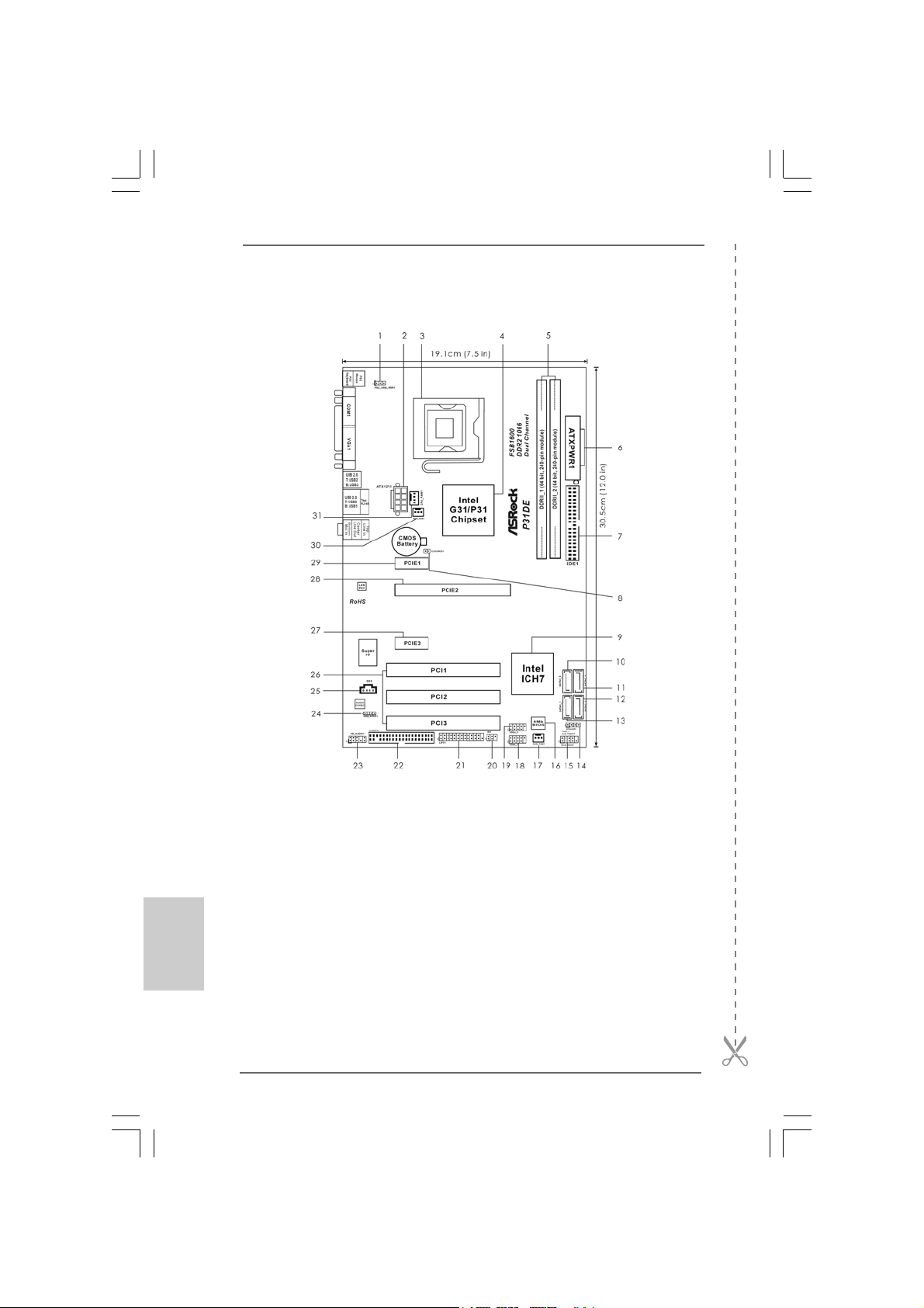
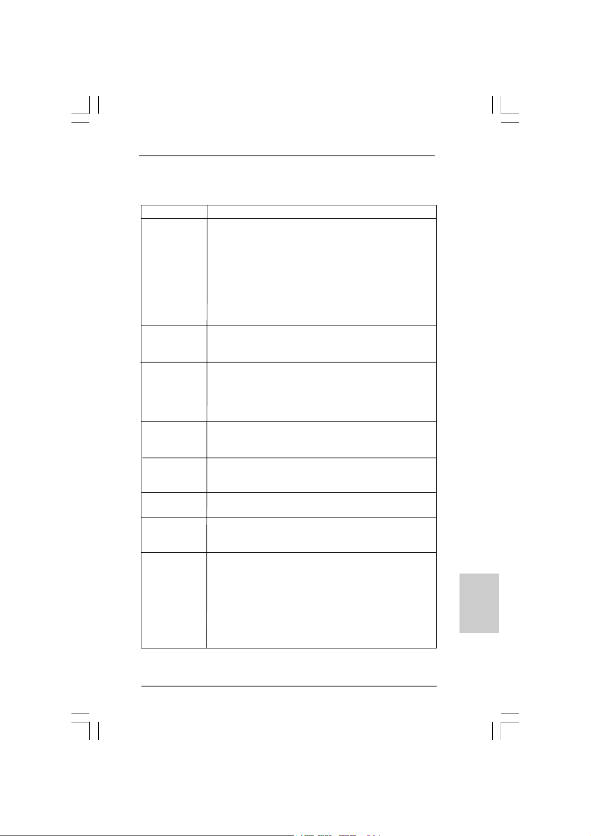
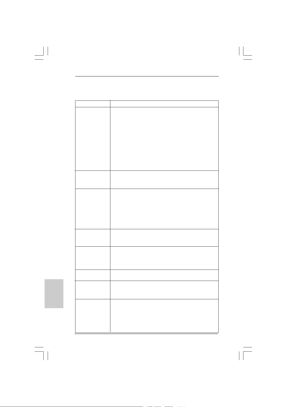
1 PS2_USB_PWR1 Jumper 17 Chassis Fan Connector (CHA_FAN1)
2 ATX 12V Connector (ATX12V1) 18 USB 2.0 Header (USB6_7, Blue)
3 775-Pin CPU Socket 19 USB 2.0 Header (USB4_5, Blue)
4 North Bridge Controller 20 Infrared Module Header (IR1)
5 2 x 240-pin DDR2 DIM M Slot s 21 Print Port Header (LPT1, Purple)
(Dual Channel: DDRII_1, DDRII_2; Yellow) 22 Floppy Connector (FLOPPY1)
6 ATX Power Connector (ATXPWR1) 23 Front Panel Audio Header
7 IDE1 Connector (IDE1, Blue) (HD_AUDIO1, Lime)
8 Clear CMOS Jumper (CLRCMOS1) 24 HDMI_SPDIF Header
9 South Bridge Controller (HDMI_SPDIF1, Yellow)
10 Third SATAII Connector (SATAII_3; Orange) 25 Internal Audio Connector: CD1 (Black)
11 Fourth SATAII Connector (SATAII_4; Orange) 26 PCI Slots (PCI1- 3)
12 Secondary SATAII Connector (SATAII_2; Red) 27 PCI Express x1 Slot (PCIE3)
13 Primary SATAII Connector (SATAII_1; Red) 28 PCI Express x16 Slot (PCIE2)
14 Chassis Speaker Header (SPEAKER 1, 29 PCI Express x1 Slot (PCIE1)
Purple) 30 Power Fan Connector (PWR_FAN1)
15 System Panel Header (PANEL1, Orange) 31 CPU Fan Connector (CPU_FAN1)
16 BIOS SPI Chip
ASRock P31DE Motherboard
Page 3
I/O PI/O P
I/O P
I/O PI/O P
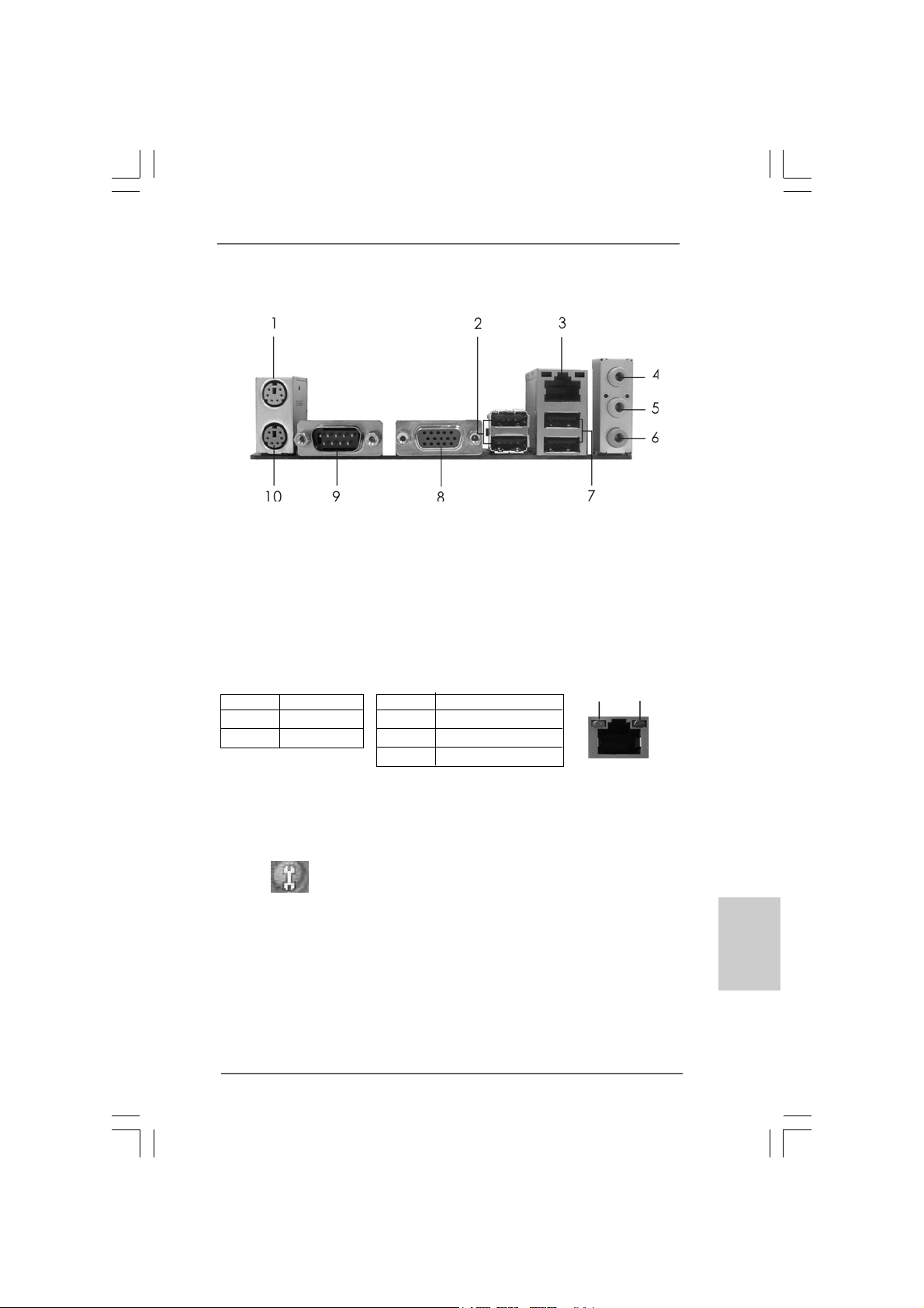
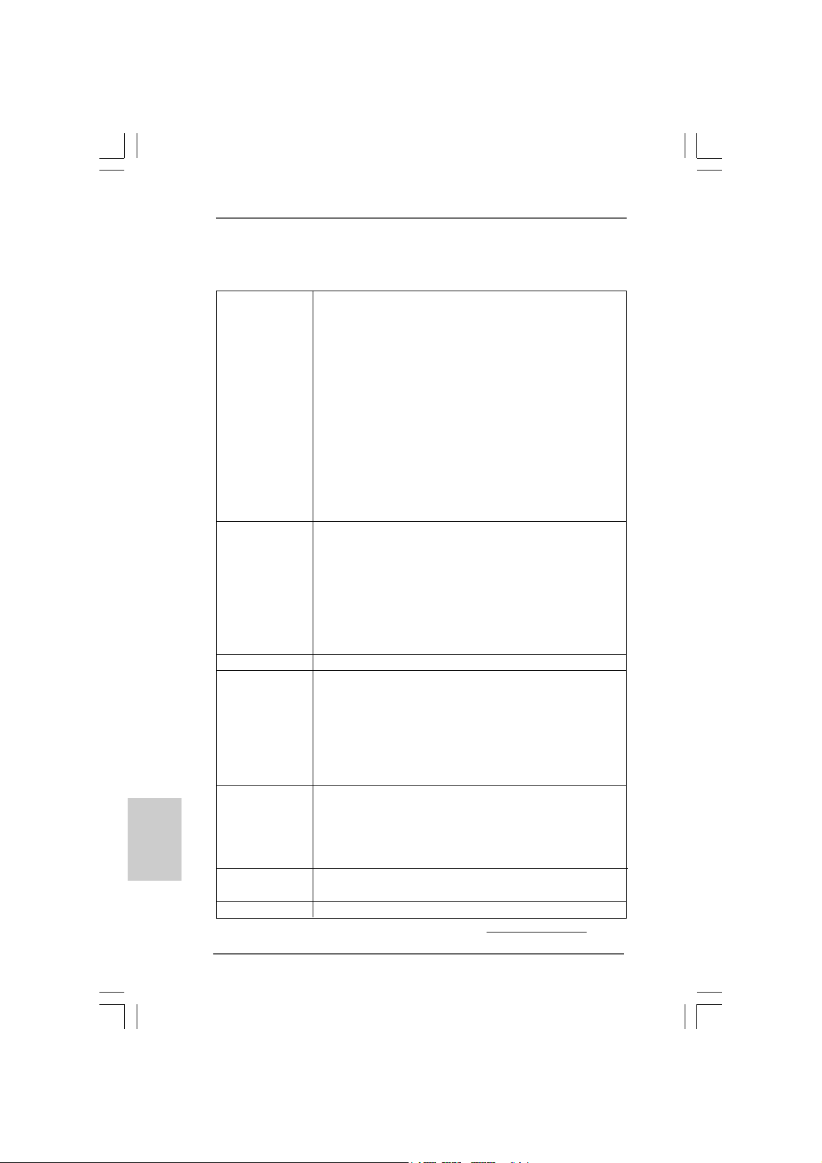
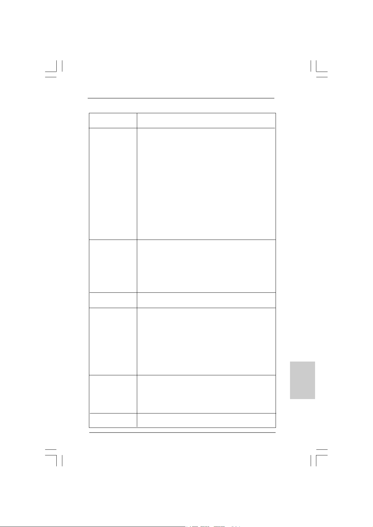
* 3 LAN RJ-45 Port 8 VGA Port
* There are two LED next to the LAN port. Please refer to the table below for the LAN port LED
indications.
anelanel
anel
anelanel
1 PS/2 Mouse Port (Green) 6 Microphone (Pink)
2 USB 2.0 Ports (USB23) 7 USB 2.0 Ports (USB01)
4 Line In (Light Blue) 9 COM Port
5 Line Out (Lime) 1 0 PS/2 Keyboard Port (Purple)
Activity/Link LED SPEED LED
Status Description Status Description
Off No Activity Off 10Mbps connection
Blinking Data Activity Orange 100Mbps connection
LAN Port LED Indications
Green 1Gbps connection
ACT/LINK
LED
LAN Port
SPEED
LED
* To enable Multi-Streaming function, you need to connect a front panel audio cable to the front
panel audio header. Please refer to below steps for the software setting of Multi-Streaming.
For Windows® XP:
After restarting your computer, you will find “Mixer” tool on your system. Please select “Mixer
ToolBox” , click “Enable playback multi-streaming”, and click “ok”. Choose “2CH” or
“4CH” and then you are allowed to select “Realtek HDA Primary output” to use Rear Speaker
and Front Speaker, or select “Realtek HDA Audio 2nd output” to use front panel audio. Then
reboot your system.
For Windows® VistaTM:
After restarting your computer, please double-click “Realtek HD Audio Manager” on the
system tray. Set “Speaker Configuration” to “Quadraphonic” or “Stereo”. Click “Device
advanced settings”, choose “Make front and rear output devices playbacks two different audio
streams simultaneously”, and click “ok”. Then reboot your system.
ASRock P31DE Motherboard
EnglishEnglish
EnglishEnglish
English
33
3
33
Page 4
1. Introduction1. Introduction
1. Introduction
1. Introduction1. Introduction
Thank you for purchasing ASRock P31DE motherboard, a reliable motherboard
produced under ASRock’s consistently stringent quality control. It delivers excellent
performance with robust design conforming to ASRock’s commitment to quality and
endurance.
This Quick Installation Guide contains introduction of the motherboard a nd step-by-ste p
installation guide. More detailed information of the motherboard can be f ound in the user
manual presented in the Support CD.
Because the motherboard specifications and the BIOS software might
be updated, the content of this manual will be subject to change without
notice. In case any modifications of this manual occur, the updated
version will be available on ASRock website without further notice. You
may find the latest VGA cards and CPU support lists on ASRock website
as well. ASRock website http://www.asrock.com
If you require technical support related to this motherboard, please visit
our website for specific information about the model you are using.
www.asrock.com/support/index.asp
1.1 P1.1 P
ackack
1.1 P
1.1 P1.1 P
ASRock P31DE Motherboard
(ATX Form Factor: 12.0-in x 7.5-in, 30.5 cm x 19.1 cm)
ASRock P31DE Quick Installation Guide
ASRock P31DE Support CD
One 80-conductor Ultra A TA 66/100 IDE Ribbon Cable
One Serial AT A (SAT A) Data Cable (Optional)
One Serial AT A (SA TA) HDD Power Cable (Optional)
One I/O Panel Shield
age Contentsage Contents
ack
age Contents
ackack
age Contentsage Contents
English
EnglishEnglish
EnglishEnglish
44
4
44
ASRock P31DE Motherboard
Page 5
1.21.2
SpecificationsSpecifications
1.2
Specifications
1.21.2
SpecificationsSpecifications
Platform - ATX Form Factor: 12.0-in x 7.5-in, 30.5 cm x 19.1 cm
CPU - LGA 775 for Intel® CoreTM 2 Extreme / CoreTM 2 Quad / Core
2 Duo / Pentium® Dual Core / Celeron® Dual Core / Celeron®,
supporting Penryn Quad Core Yorkfield and Dual Core
Wolfdale processors
- Compatible with all FSB1600/1333/1066/800MHz CPUs
(see CAUTION 1)
- Supports Hyper-Threading Technology (see CAUTION 2)
- Supports Untied Overclocking Technology (see CAUTION 3)
- Supports EM64T CPU
Chipset - Intel® G31 & ICH7
- Northbridge: Intel® G31/P31
- Southbridge: Intel® ICH7
Memory - Dual Channel DDR2 Memory Technology (see CAUTION 4)
- 2 x DDR2 DIMM slots
- Supports DDR2 1066/800/667 non-ECC, un-buf fered memory
(see CAUTION 5)
- Max. capacity of system memory: 8GB (see CAUTION 6)
Expansion Slot - 1 x PCI Express x16 slot
- 2 x PCI Express x1 slots
- 3 x PCI slots
Graphics - Intel® Graphics Media Accelerator 3100
- Pixel Shader 2.0, Dire ctX 9.0
- Max. shared memory 384MB (see CAUTION 7)
Audio - 5.1 CH Windows® VistaTM Premium Level HD Audio
(Realtek ALC662 Audio Code c)
LAN - PCIE x1 Gigabit LAN 10/100/1000 Mb/s
- Realtek RTL81 1 1DL
- Supports Wa ke-On-LAN
Rear Panel I/O I/O Panel
- 1 x PS/2 Mouse Port
- 1 x PS/2 Keyboard Port
- 1 x Serial Port: COM1
- 1 x VGA Port
- 4 x Ready-to-Use USB 2.0 Ports
- 1 x RJ-45 LAN Port with LED (ACT/LINK LED a nd SPEED LED)
- HD Audio Jack: Line in / Front Spea ker / Microphone
TM
EnglishEnglish
EnglishEnglish
English
ASRock P31DE Motherboard
55
5
55
Page 6
English
EnglishEnglish
EnglishEnglish
Connector - 4 x SATAII 3.0 Gb/s conne ctors (No Support for RAID and
“Hot Plug” functions) (see CAUTION 8)
- 1 x ATA100 IDE conne ctor (supports 2 x IDE devices)
- 1 x Floppy connector
- 1 x IR header
- 1 x Print port header
- 1 x HDMI_SPDIF header
- CPU/Chassis/Power FAN connector
- 24 pin A TX power conne ctor
- 8 pin 12V power connector
- CD in header
- Front panel audio connector
- 2 x USB 2.0 headers (support 4 USB 2.0 ports)
(see CAUTION 9)
BIOS Feature - 4Mb AMI BIOS
- AMI Legal BIOS
- Supports “Plug and Play”
- ACPI 1.1 Compliance Wa ke Up Events
- Supports jumperfree
- SMBIOS 2.3.1 Support
- CPU, VCCM V oltage Multi-a djustment
- Supports Smart BIOS
Support CD - Drivers, Utilities, AntiV irus Software (T ri al Version)
Unique Feature - ASRock OC Tuner (see CAUTION 10)
- Intelligent Energy Saver (see CAUTION 11)
- Instant Boot
- Hybrid Booster:
- CPU Frequency Stepless Control (see CAUTION 12)
- ASRock U-COP (see CAUTION 13)
- Boot Failure Guard (B.F.G.)
Hardware - CPU T e mperature Sensing
Monitor - Chassis Temperature Sensing
- CPU/Chassis/Power Fa n Ta chometer
- CPU Quiet Fan
- Voltage Monitoring: +12V, +5V, +3.3V, Vcore
OS - Microsoft® Windows® 2000 / XP / XP 64-bit / Vista
VistaTM 64-bit compliant
Certifications - FCC, CE, WHQL
* For detailed product information, please visit our website: http://www.asrock.com
TM
/
66
6
66
ASRock P31DE Motherboard
Page 7
WARNING
Please realize that there is a certain risk involved with overclocking, including
adjusting the setting in the BIOS, applying Untied Overclocking Technology, or using
the third-party overclocking tools. Overclocking may affect your system stability, or
even cause damage to the components and devices of your system. It should be
done at your own risk and expense. We are not responsible for possible damage
caused by overclocking.
CAUTION!
1. FSB1600-CPU will operate in overclocking mode. Under this situation,
PCIE frequency will also be overclocked to 120MHz.
2. About the setting of “Hyper Threading Technology”, please check page
32 of “User Manual” in the support CD.
3. This motherboard supports Untied Overclocking Technology. Please read
“Untied Overclocking Technology” on page 19 for details.
4. This motherboard supports Dual Channel Memory Technology. Before
you implement Dual Channel Memory Technology, make sure to read
the installation guide of memory modules on page 12 for proper
installation.
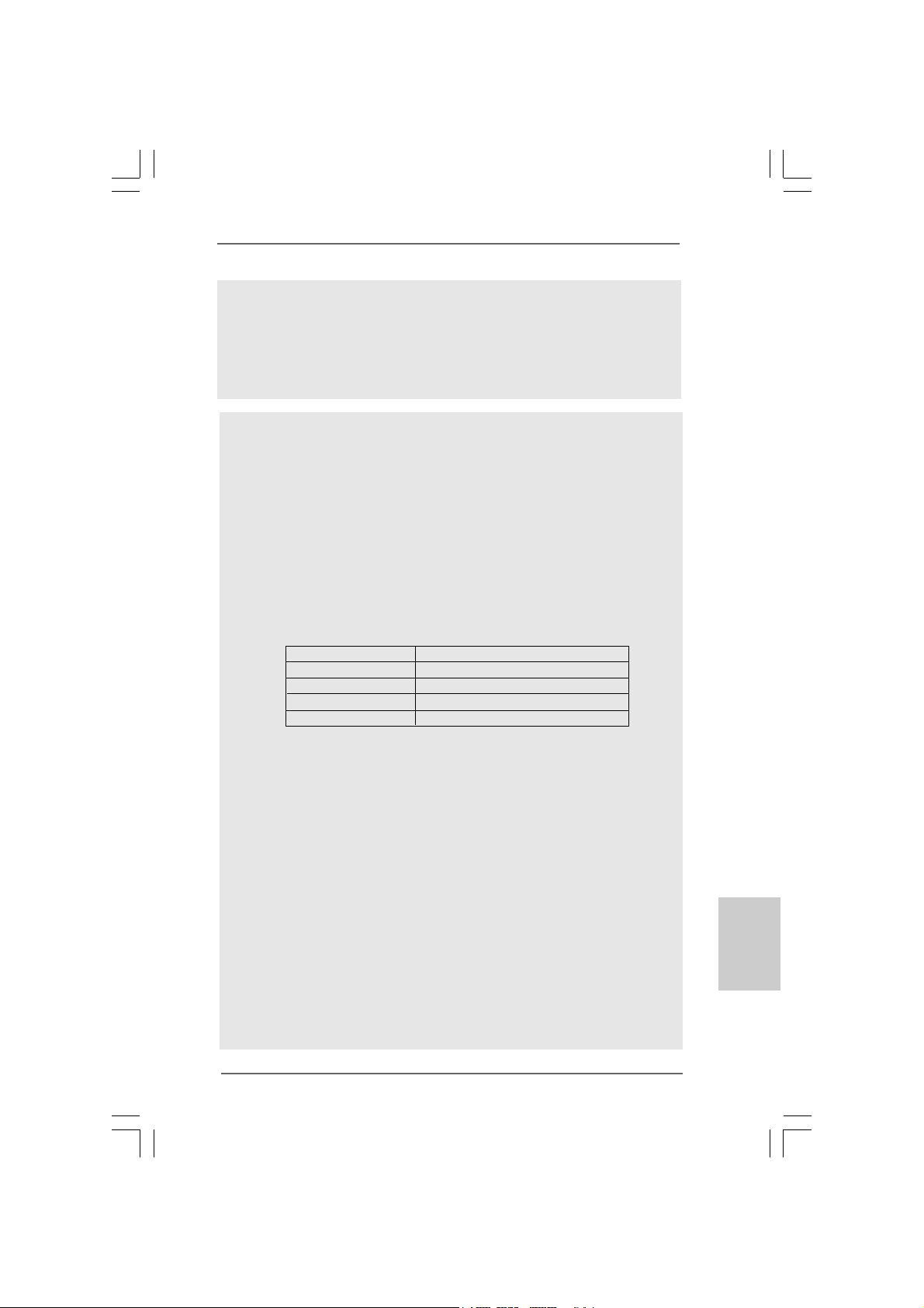
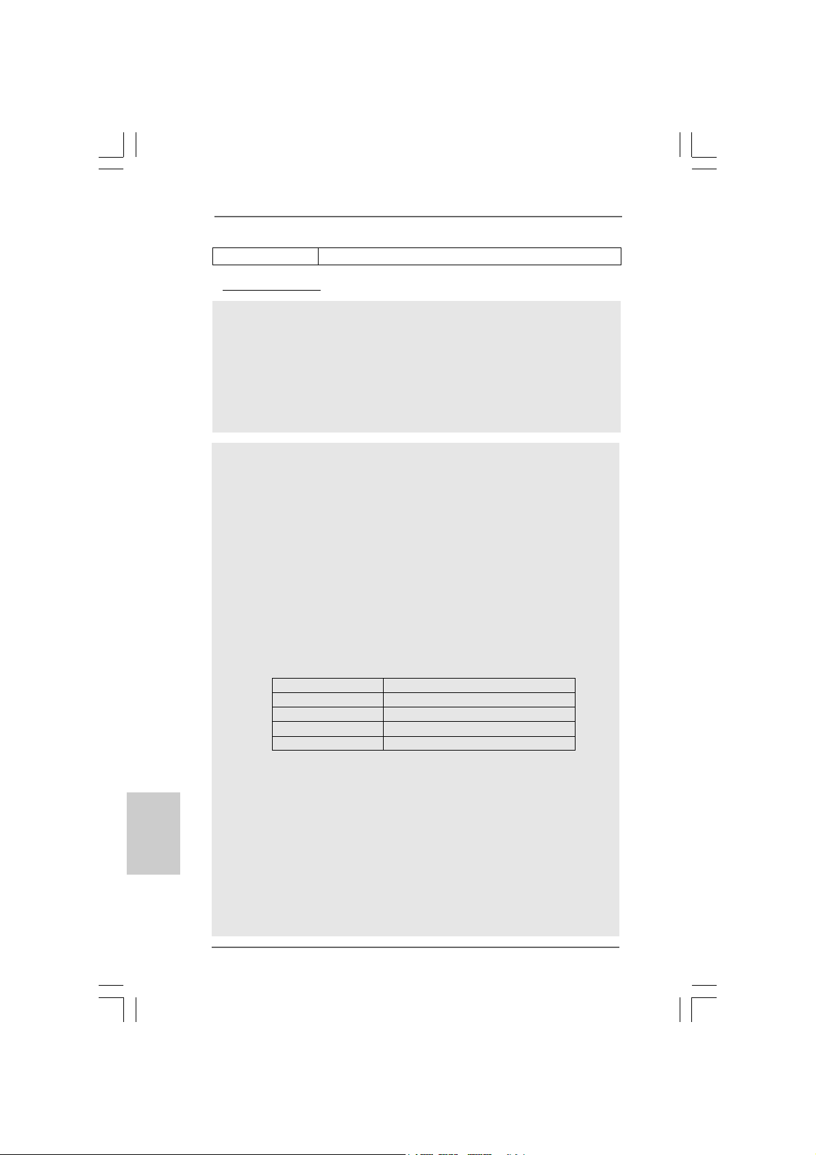
5. Please check the table below for the CPU FSB frequency and its
corresponding memory support frequency.
CPU FSB Frequency Memory Support Frequency
1600 DDR2 800, DDR2 1066 *
1333 DDR2 667, DDR2 800, DDR2 1066 *
1066 DDR2 667, DDR2 800, DDR2 1066
800 DDR2 667, DDR2 800
* When you use a FSB1600-CPU on this motherboard, it will run at
DDR2 960 if you adopt a DDR2 1066 memory module. When you use
a FSB1333-CPU on this motherboard, it will run at DDR2 1000 if you
adopt a DDR2 1066 memory module.
* DDR2 1066 memory module will operate in overclocking mode.
6. Due to the operating system limitation, the actual memory size may be
less than 4GB for the reservation for system usage under Windows® XP
and Windows® VistaTM. For Windows® XP 64-bit and Windows® Vista
64-bit with 64-bit CPU, there is no such limitation.
7. The maximum shared memory size is defined by the chipset vendor
and is subject to change. Please check Intel® website for the latest
information.
8. Before installing SATAII hard disk to SA TAII connector, ple ase read the “SA TAII
Hard Disk Setup Guide” on page 25 of “User Manual” in the support CD to
adjust your SATAII hard disk drive to SATAII mode. You can also connect
SATA hard disk to SATAII connector directly.
9. Power Management for USB 2.0 works fine under Microsoft® Windows
VistaTM 64-bit / VistaTM / XP 64-bit / XP SP1 or SP2 / 2000 SP4.
TM
®
EnglishEnglish
EnglishEnglish
English
ASRock P31DE Motherboard
77
7
77
Page 8
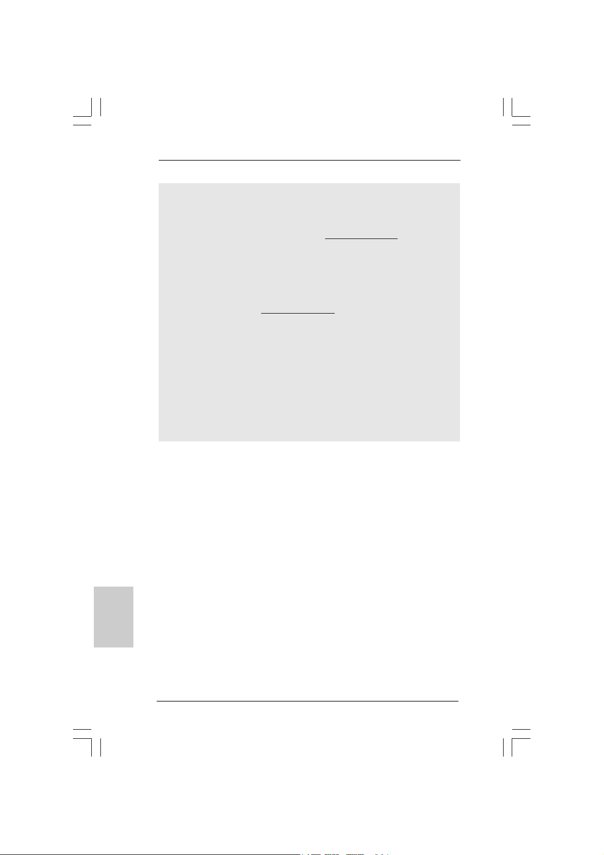
10. It is a user-friendly ASRock overclocking tool which allows you to surveil
your system by hardware monitor function and overclock your hardware
devices to get the best system performance under Windows
environment. Please visit our website for the operation procedures of
ASRock OC Tuner. ASRock website: http://www.asrock.com
11. Featuring an advanced proprietary hardware and software design,
Intelligent Energy Saver is a revolutionary technology that delivers
unparalleled power savings. In other words, it is able to provide exceptional power saving and improve power efficiency without sacrificing
computing performance. Please visit our website for the operation procedures of Intelligent Energy Saver.
ASRock website: http://www.asrock.com
12. Although this motherboard offers stepless control, it is not recommended to perform over-clocking. Frequencies other than the recommended CPU bus frequencies may cause the instability of the system
or damage the CPU.
13. While CPU overheat is detected, the system will automatically shutdown.
Before you resume the system, please check if the CPU fan on the
motherboard functions properly and unplug the power cord, then plug it
back again. To improve heat dissipation, remember to spray thermal
grease between the CPU and the heatsink when you install the PC
system.
®
English
EnglishEnglish
EnglishEnglish
88
8
88
ASRock P31DE Motherboard
Page 9
2.2.
InstallationInstallation
2.
Installation
2.2.
InstallationInstallation
Pre-installation PrecautionsPre-installation Precautions
Pre-installation Precautions
Pre-installation PrecautionsPre-installation Precautions
Take note of the following precautions before you install motherboard components or change any motherboard settings.
1. Unplug the power cord from the wall socket before touching any
component. Failure to do so may cause severe damage to the
motherboard, peripherals, and/or components.
2. To avoid damaging the motherboard components due to static
electricity, NEVER place your motherboard directly on the carpet
or the like. Also remember to use a grounded wrist strap or touch
a safety grounded object before you handle components.
3. Hold components by the edges and do not touch the ICs.
4. Whenever you uninstall any component, place it on a grounded
antstatic pad or in the bag that comes with the component.
5. When placing screws into the screw holes to secure the
motherboard to the chassis, please do not over-tighten the
screws! Doing so may damage the motherboard.
2.12.1
CPU InstallationCPU Installation
2.1
CPU Installation
2.12.1
CPU InstallationCPU Installation
For the installation of Intel 775-LAND CPU,
please follow the steps below.
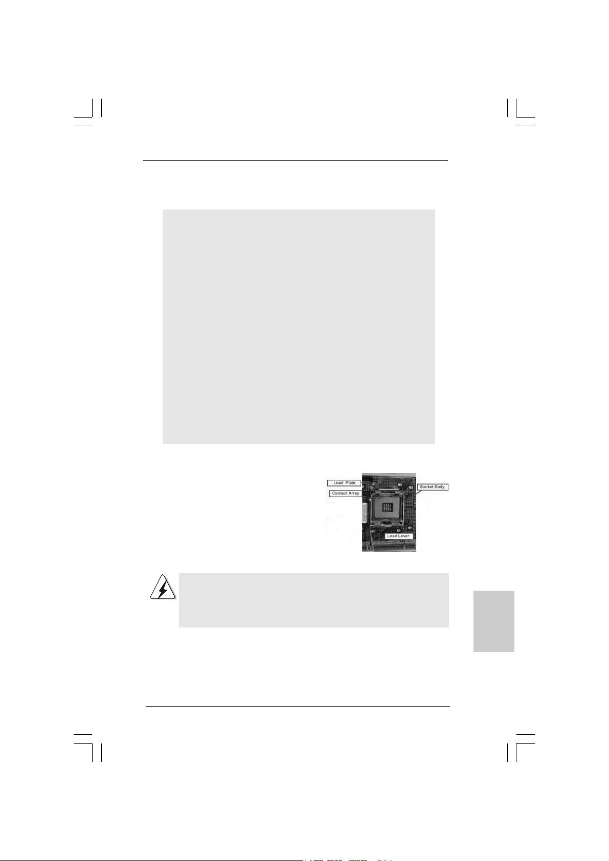
775-Pin Socket Overview
Before you insert the 775-LAND CPU into the socket, please check if
the CPU surface is unclean or if there is any bent pin on the socket.
Do not force to insert the CPU into the socket if above situation is
found. Otherwise, the CPU will be seriously damaged.
ASRock P31DE Motherboard
EnglishEnglish
EnglishEnglish
English
99
9
99
Page 10
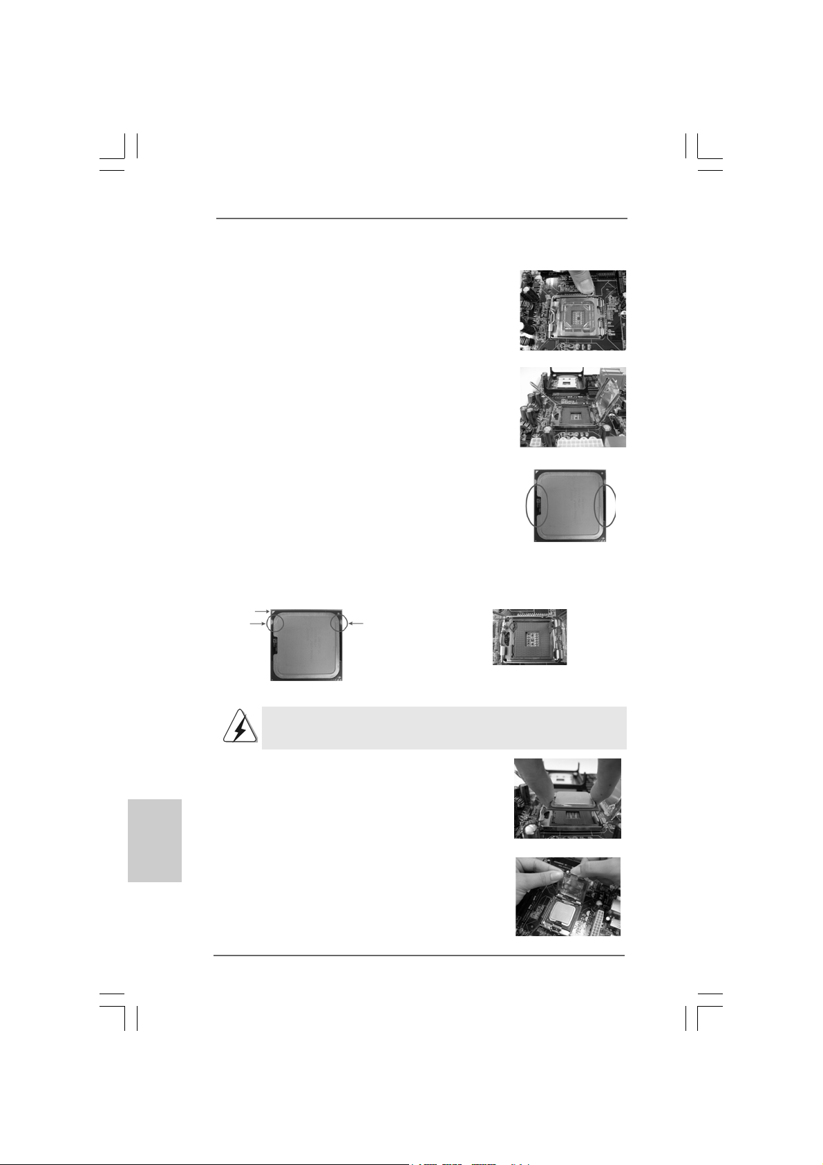
Step 1. Open the socket:
Step 1-1. Disengaging the lever by depressing
down and out on the hook to clear
retention tab.
Step 1-2. Rotate the load lever to fully open po-
sition at approximately 135 degrees.
Step 1-3. Rotate the load plate to fully open po-
sition at approximately 100 degrees.
Step 2. Insert the 775-LAND CPU:
Step 2-1. Hold the CPU by the edges where are
marked with black lines.
Step 2-2. Orient the CPU with IHS (Integrated
Heat Sink) up. Locate Pin1 and the two
orientation key notches.
Pin1
orientation
key notch
orientation
key notch
Pin1
alignment key
black line
black line
alignment key
English
EnglishEnglish
EnglishEnglish
1010
10
1010
775-Pin Socket
775-LAND CPU
For proper inserting, please ensure to match the two orientation key
notches of the CPU with the two alignment keys of the socket.
Step 2-3. Carefully place the CPU into the socket
by using a purely vertical motion.
Step 2-4. Verify that the CPU is within the socket
and properly mated to the orient keys.
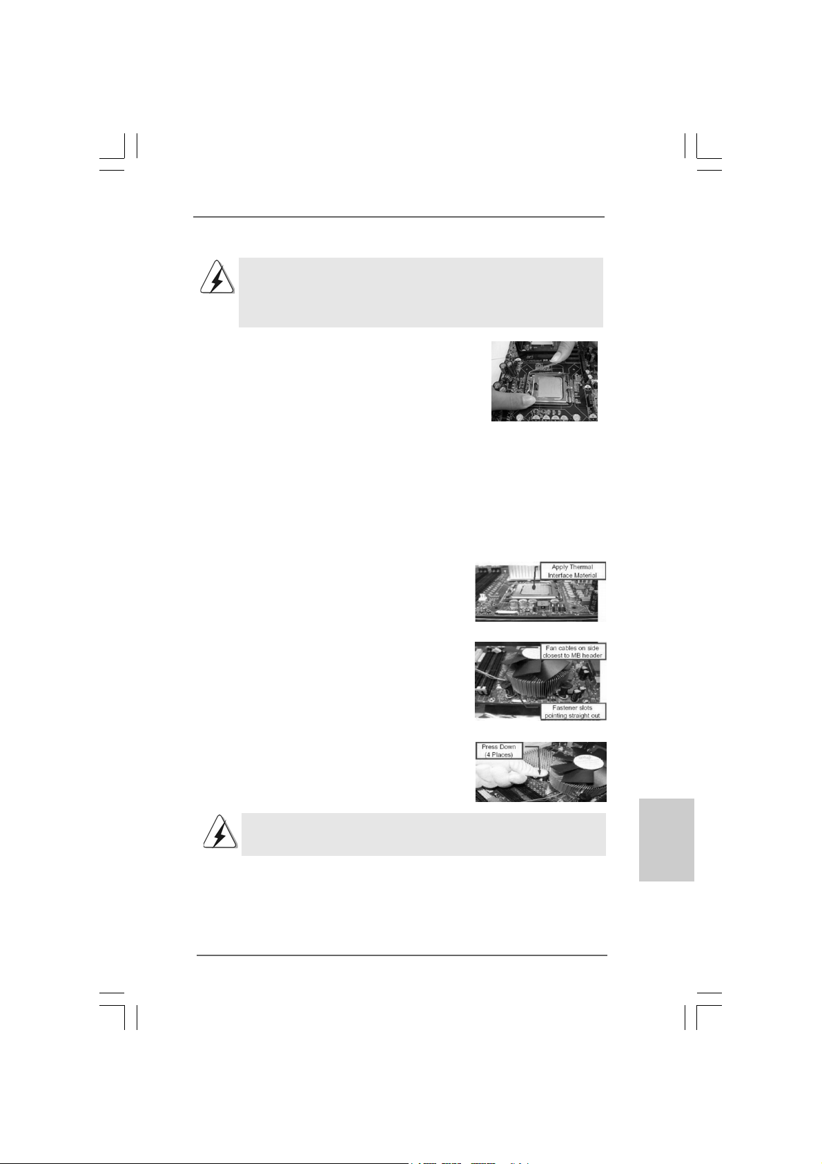
Step 3. Remove PnP Cap (Pick and Pla ce Cap):
Use your left hand index finger and thumb to
support the load plate edge, engage PnP cap
with right hand thumb and peel the cap from the
socket while pressing on center of PnP cap to
assist in removal.
ASRock P31DE Motherboard
Page 11
1. It is recommended to use the cap tab to handle and avoid kicking
off the PnP cap.
2. This cap must be placed if returning the motherboard for after
service.
Step 4. Close the socket:
Step 4-1. Rotate the load plate onto the IHS.
Step 4-2. While pressing down lightly on load
plate, engage the load lever.
Step 4-3. Secure load lever with load plate tab
under retention tab of load lever.
2.22.2
Installation of CPU Fan and HeatsinkInstallation of CPU Fan and Heatsink
2.2
Installation of CPU Fan and Heatsink
2.22.2
Installation of CPU Fan and HeatsinkInstallation of CPU Fan and Heatsink
For proper installation, please kindly refer to the instruction manuals of your CPU fan
and heatsink.
Below is an example to illustrate the installation of the heatsink for 775-LAND CPU.
Step 1. Apply thermal interface material onto center
of IHS on the socket surface.
Step 2. Place the heatsink onto the socket. Ensure
fan cables are oriented on side closest to the
CPU fan connector on the motherboard
(CPU_FAN1, see page 2, No. 31).
Step 3. Align fasteners with the motherboard
throughholes.
Step 4. Rotate the fastener clockwise, then press
down on fastener caps with thumb to install
and lock. Repeat with remaining fasteners.
If you press down the fasteners without rotating them clockwise,
the heatsink cannot be secured on the motherboard.
Step 5. Connect fan header with the CPU fan
connector on the motherboard.
Step 6. Secure excess cable with tie-wrap to ensure
cable does not interfere with fan operation or
contact other components.
ASRock P31DE Motherboard
1111
11
1111
EnglishEnglish
EnglishEnglish
English
Page 12
2.3 Installation of Memory Modules (DIMM)2.3 Installation of Memory Modules (DIMM)
2.3 Installation of Memory Modules (DIMM)
2.3 Installation of Memory Modules (DIMM)2.3 Installation of Memory Modules (DIMM)
P31DE motherboard provides two 240-pin DDR2 (Double Data Rate 2) DIMM slots,
and supports Dual Channel Memory Technology. For dual channel configuration, you
always need to install two identical (the same brand, speed, size and chip-type)
memory modules in the DD R2 DIMM slots to a ctivate Dual Cha nnel Memory Technology .
Otherwise, it will operate at single channel mode.
1. It is not allowed to install a DDR memory module into DDR2 slot;
otherwise, this motherboard and DIMM may be damaged.
2. If you install only one memory module or two non-identical memory
modules, it is unable to a ctivate the Dual Cha nnel Memory Technology.
Installing a DIMMInstalling a DIMM
Installing a DIMM
Installing a DIMMInstalling a DIMM
Please make sure to disconnect power supply before adding or
removing DIMMs or the system components.
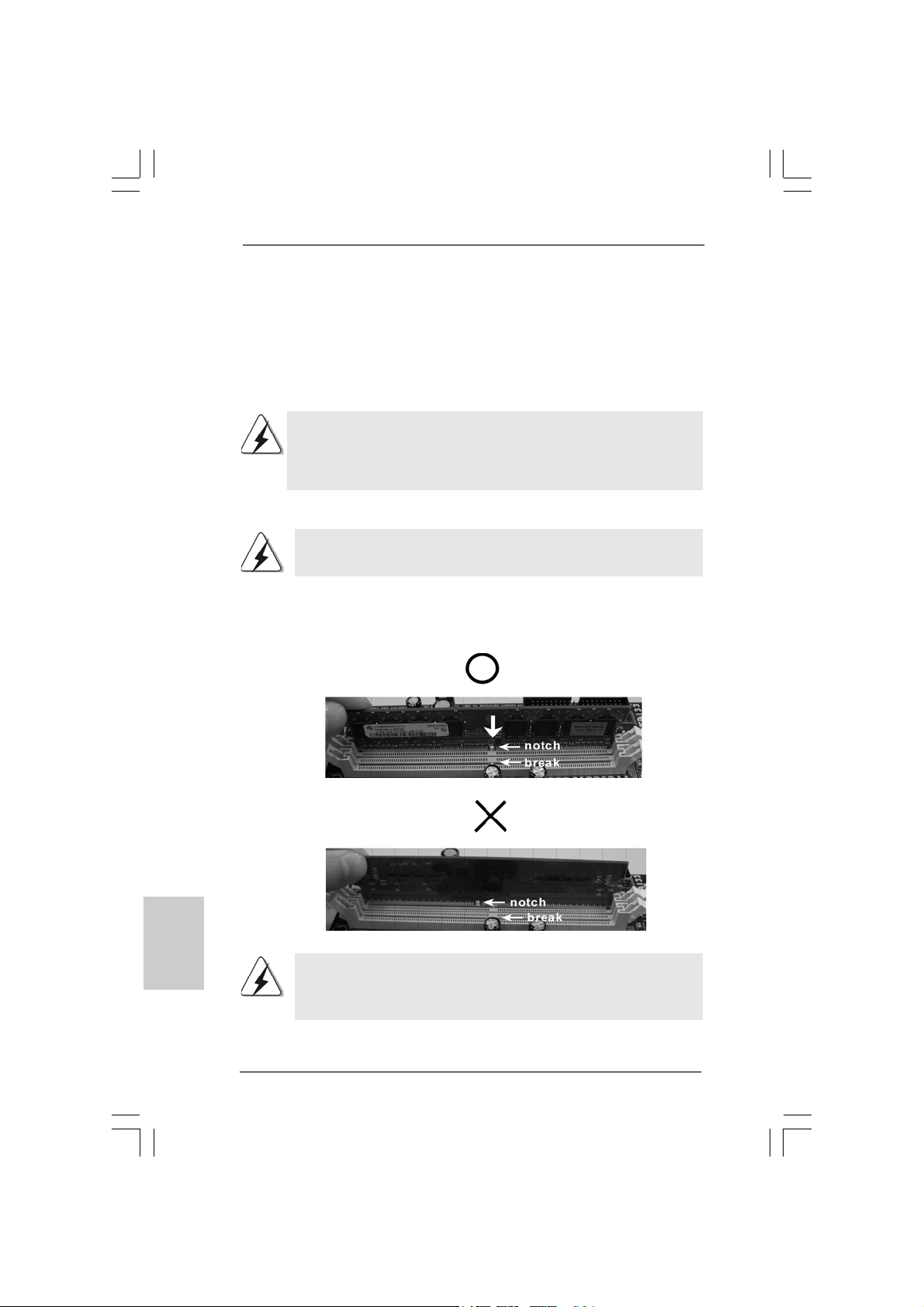
Step 1. Unlock a DIMM slot by pressing the retaining clips outward.
Step 2. Align a DIMM on the slot such that the notch on the DIMM matches the break
on the slot.
English
EnglishEnglish
EnglishEnglish
1212
12
1212
The DIMM only fits in one correct orientation. It will cause permanent
damage to the motherboard and the DIMM if you force the DIMM into the
slot at incorrect orientation.
Step 3. Firmly insert the DIMM into the slot until the retaining clips at both ends fully
snap back in place and the DIMM is properly seated.
ASRock P31DE Motherboard
Page 13
2.4 Expansion Slots (PCI and PCI Express Slots)2.4 Expansion Slots (PCI and PCI Express Slots)
2.4 Expansion Slots (PCI and PCI Express Slots)
2.4 Expansion Slots (PCI and PCI Express Slots)2.4 Expansion Slots (PCI and PCI Express Slots)
There are 3 PCI slots and 3 PCI Express slots on this motherboard.
PCI slots: PCI slots are used to install expansion cards that have the 32-bit PCI
interface.
PCIE slots:
PCIE1 / PCIE3 (PCIE x1 slot) is used for PCI Express cards with x1 lane
width cards, such as Gigabit LAN card, SAT A2 card, etc.
PCIE2 (PCIE x16 slot) is used for PCI Express cards with x16 lane
width graphics cards.
If you install the add-on PCI Express VGA card to PCIE2 (PCIE x16 slot),
the onboard VGA will be disabled. If you install the add-on PCI Express
VGA card to PCIE2 (PCIE x16 slot) and adjust the “Internal Graphics
Mode Select” BIOS option to [Enabled], the onboard VGA will be enabled,
and the primary screen will be onboard VGA.
Installing an expansion cardInstalling an expansion card
Installing an expansion card
Installing an expansion cardInstalling an expansion card
Step 1. Before installing the expansion card, please make sure that the power supply
is switched off or the power cord is unplugged. Plea se read the documentation
of the expansion card a nd ma ke necessary hardware
settings for the card before you start the installation.
Step 2. Remove the bracket facing the slot that you intend to use. Keep the screws
for later use.
Step 3. Align the card connector with the slot and press firmly until the card is com-
pletely seated on the slot.
Step 4. Fasten the card to the chassis with screws.
ASRock P31DE Motherboard
1313
13
1313
EnglishEnglish
EnglishEnglish
English
Page 14
2.5 Jumpers Setup2.5 Jumpers Setup
2.5 Jumpers Setup
2.5 Jumpers Setup2.5 Jumpers Setup
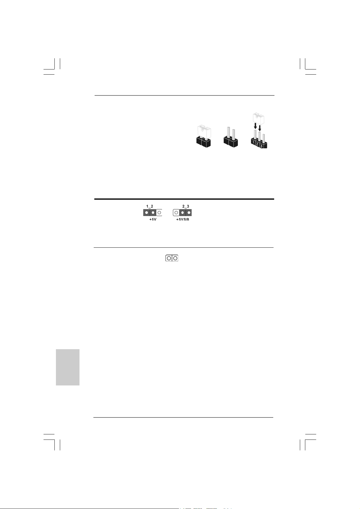
The illustration shows how jumpers are
setup. When the jumper cap is placed on
pins, the jumper is “Short”. If no jumper cap
is placed on pins, the jumper is “Open”. The
illustration shows a 3-pin jumper whose pin1
and pin2 are “Short” when jumper cap is
placed on these 2 pins.
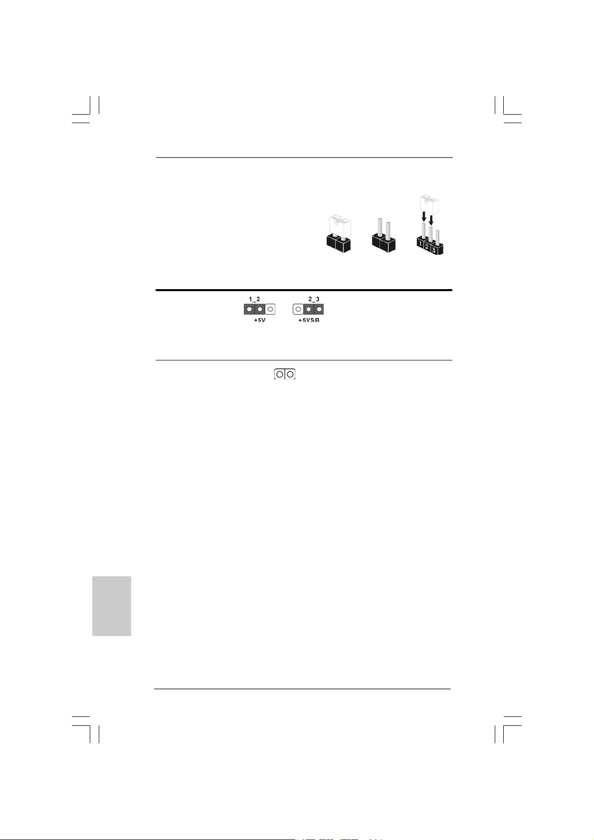
Jumper Setting Description
PS2_USB_PWR1 Short pin2, pin3 to enable
(see p.2 No. 1) +5VSB (standby) for PS/2
Note: To select +5VSB, it requires 2 Amp and higher standby current provided by
power supply.
Clear CMOS
(CLRCMOS1, 2-pin jumper)
(see p.2 No. 8)
Note: CLRCMOS1 allows you to clear the data in CMOS. The data in CMOS includes
system setup information such as system password, date, time, and system
setup parameters. To clear and reset the system parameters to default setup,
please turn off the computer and unplug the power cord from the power
supply. After waiting for 15 seconds, use a jumper cap to short 2 pins on
CLRCMOS1 for 5 seconds.
2-pin jumper
Short Open
or USB wake up events.
English
EnglishEnglish
EnglishEnglish
1414
14
1414
ASRock P31DE Motherboard
Page 15
2.6 Onboard Headers and Connectors2.6 Onboard Headers and Connectors
2.6 Onboard Headers and Connectors
2.6 Onboard Headers and Connectors2.6 Onboard Headers and Connectors
Onboard headers and connectors are NOT jumpers. Do NOT place
jumper caps over these headers and connectors. Placing jumper caps
over the headers and connectors will cause permanent damage of the
motherboard!
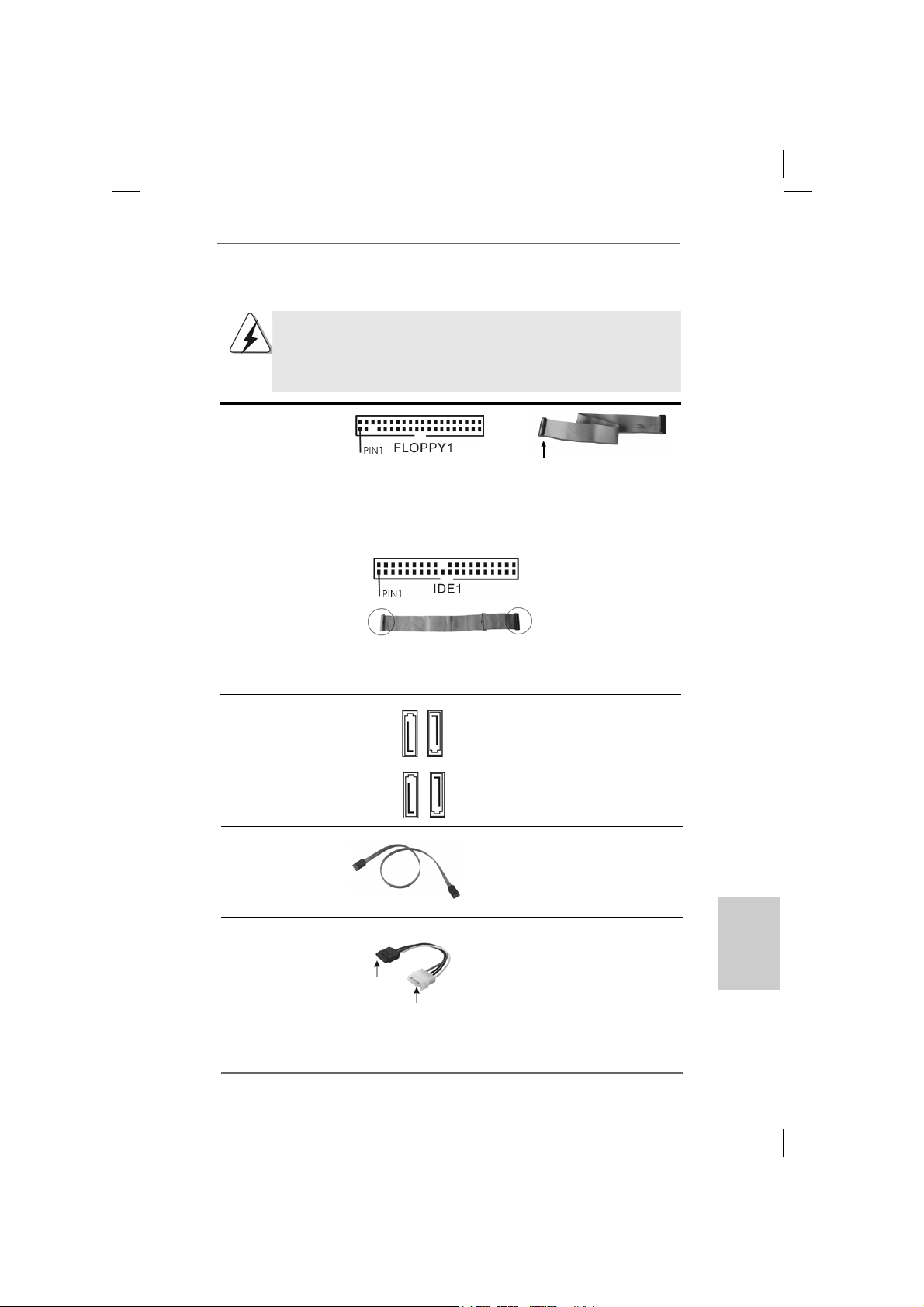
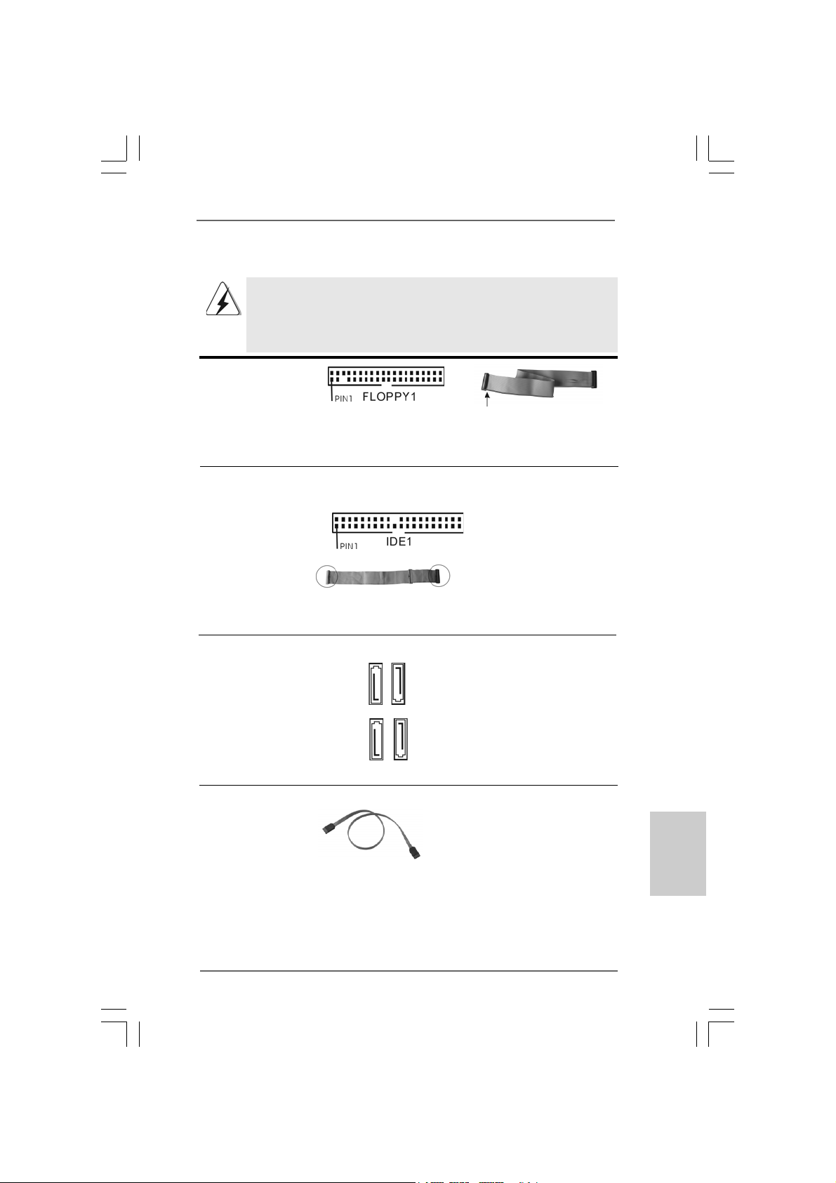
FDD connector
(33-pin FLOPPY1)
(see p.2 No. 22)
the red-striped side to Pin1
Note: Make sure the red-striped side of the cable is plugged into Pin1 side of the
connector.
Primary IDE connector (Blue)
(39-pin IDE1, see p.2 No. 7)
connect the blue end
to the motherboard
connect the black end
to the IDE devices
80-conductor ATA 66/100 cable
Note: Please re fer to the instruction of your IDE device vendor for the details.
Serial A T AII Connectors These Serial A T AII (SA T AII)
(SATAII_1: see p.2, No. 13) connectors support SA T AII
(SATAII_2: see p.2, No. 12) or SATA hard disk f or internal
(SATAII_3: see p.2, No. 10) storage devices. The current
(SATAII_4: see p.2, No. 11) SATAII interface allows up to
SATAII_3
SATAII_1
SATAII_4
3.0 Gb/s data tra ns fer rate.
SATAII_2
Serial A TA (SA TA) Either end of the SATA data ca ble
Data Cable can be connected to the SATA /
(Optional) SATAII hard disk or the SATAII
connector on the motherboard.
Serial ATA (SATA) Please connect the black end of
Power Cable SATA power cable to the power
(Optional) connector on each drive. Then
connect to the SAT A
HDD power connector
connect to the
power supply
connect the white end of SATA
power cable to the power
connector of the power supply.
EnglishEnglish
EnglishEnglish
English
ASRock P31DE Motherboard
1515
15
1515
Page 16
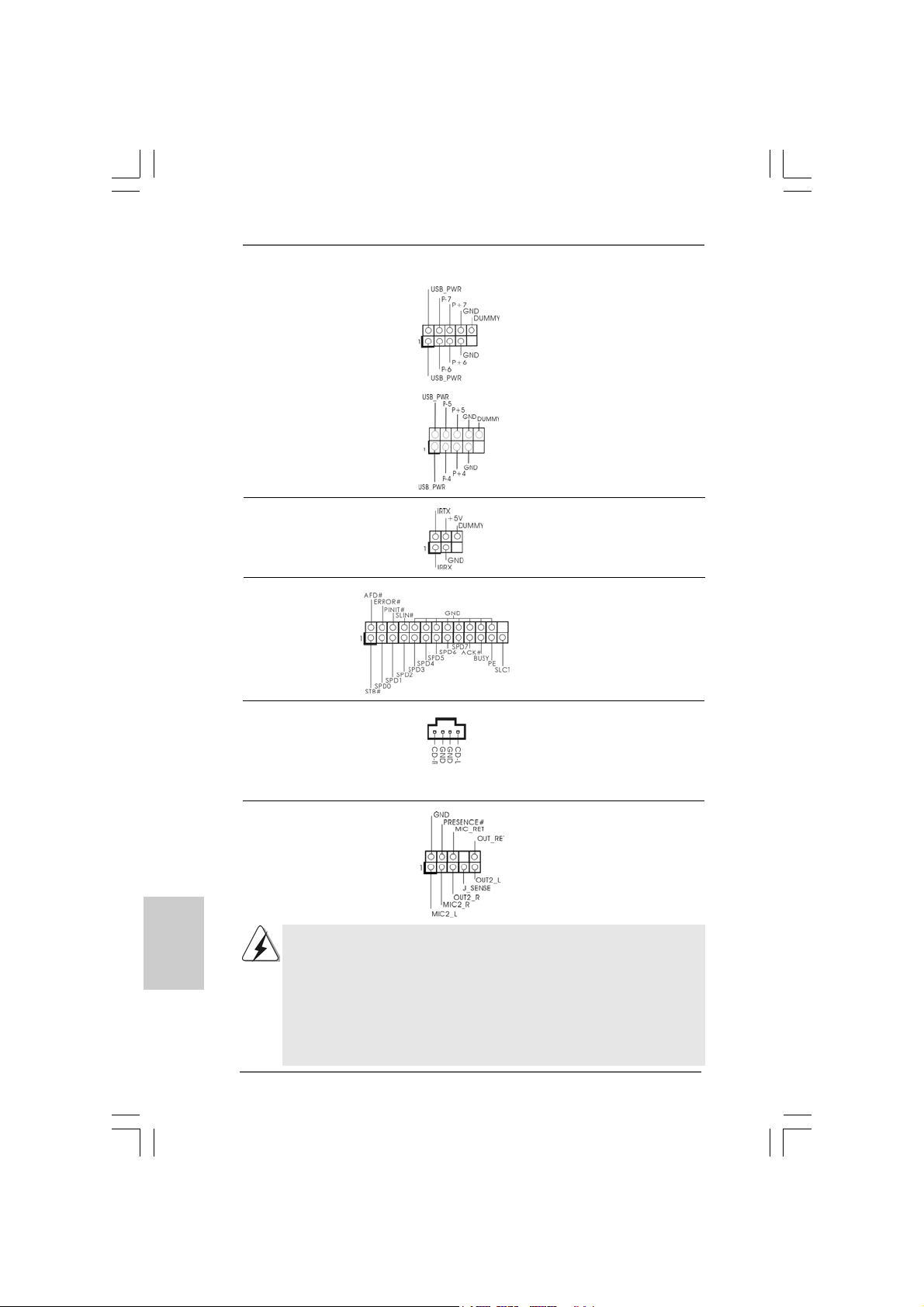
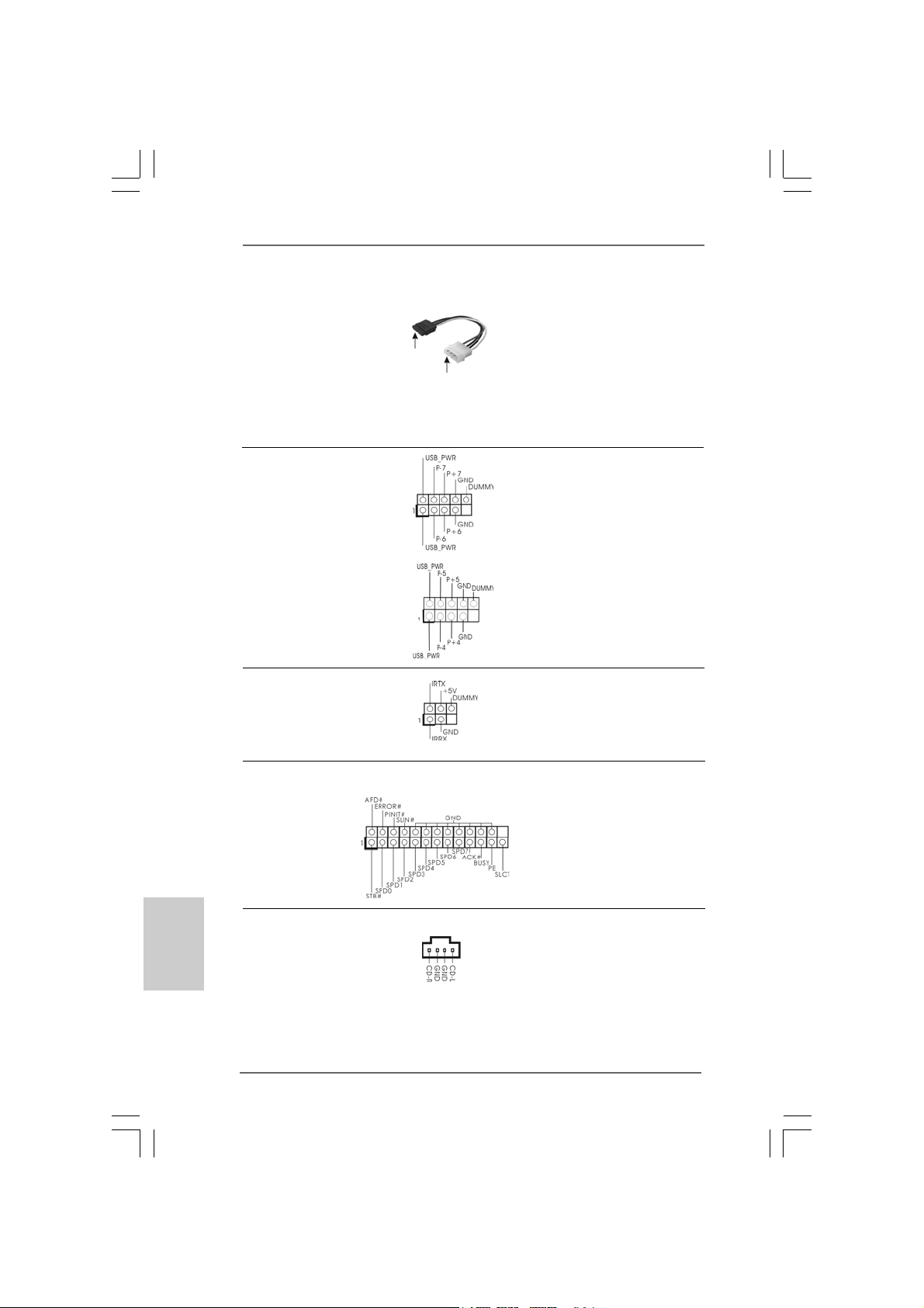
USB 2.0 Headers Besides four default USB 2.0
(9-pin USB6_7) ports on the I/O panel, there are
(see p.2 No. 18) two USB 2.0 headers on this
motherboard. Each USB 2.0
header can support two USB
2.0 ports.
(9-pin USB4_5)
(see p.2 No. 19)
Infrared Module Header This header supports an
(5-pin IR1) optional wireless transmitting
(see p.2 No. 20) and receiving infrared module.
Print Port Header This is an interface for print
(25-pin LPT1) port cable that allows
(see p.2 No. 21) convenient connection of printer
devices.
Internal Audio Connector This connector allows you
(4-pin CD1) to receive stereo audio input
(CD1: see p.2 No. 25) from sound sources such as
CD1
a CD-ROM, D VD-ROM, TV
tuner card, or MPEG card.
English
EnglishEnglish
EnglishEnglish
1616
16
1616
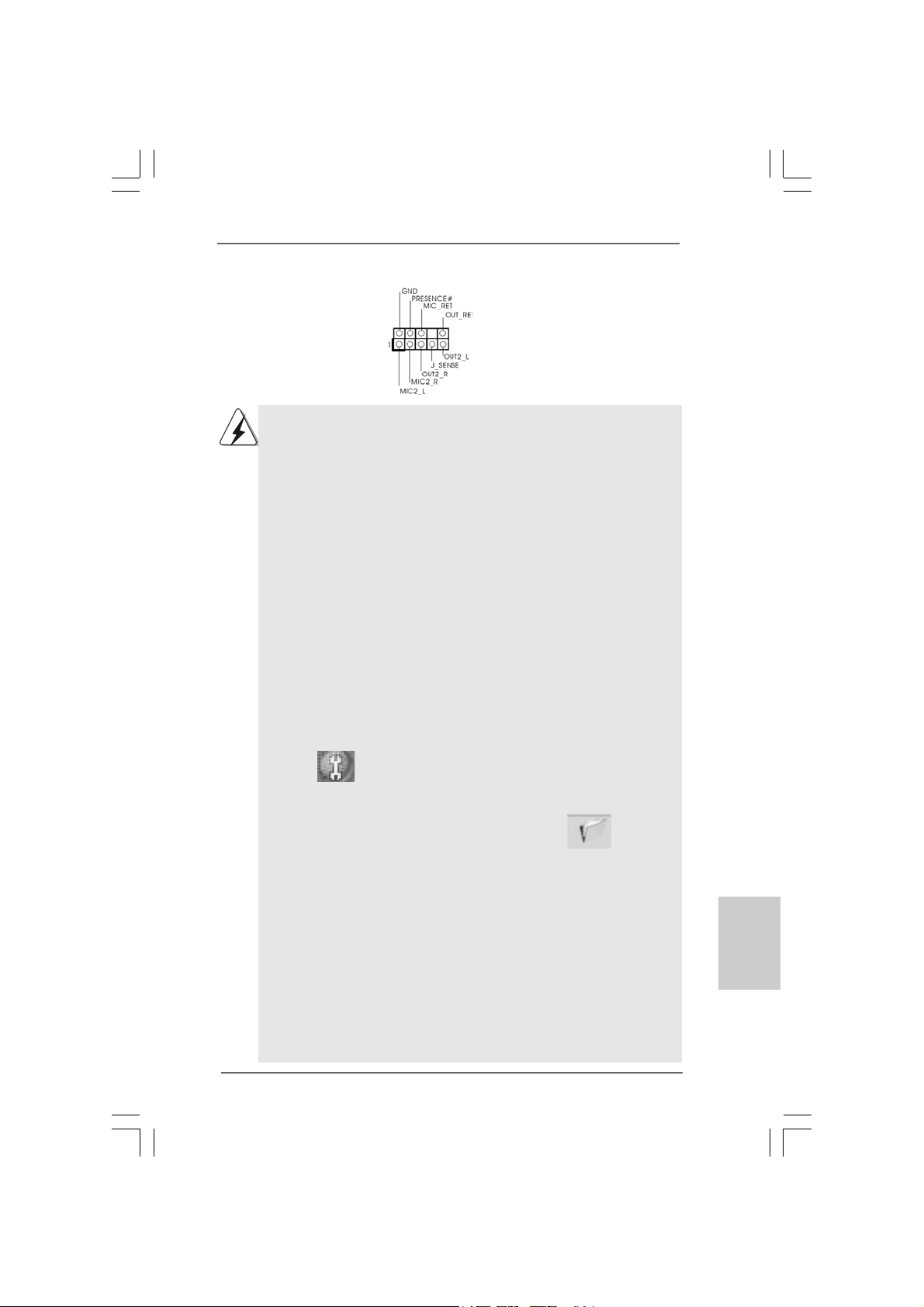
Front Panel Audio Hea der This is an interface f or front
(9-pin HD_AUDIO1) panel audio cable that allows
(see p.2 No. 23) convenient connection and
control of audio devices.
1. High Definition Audio supports Jack Sensing, but the panel wire on
the chassis must support HDA to function correctly. Please follow the
instruction in our manual and chassis manual to install your system.
2. If you use AC’97 audio panel, please install it to the front panel audio
header as below:
A. Connect Mic_IN (MIC) to MIC2_L.
B. Connect Audio_R (RIN) to OUT2_R and Audio_L (LIN) to OUT2_L.
C. Connect Ground (GND) to Ground (GND).
ASRock P31DE Motherboard
Page 17
D. MIC_RET and OUT_RET are for HD audio panel only. You don’t
need to connect them for AC’97 audio panel.
E. Enter BIOS Setup Utility. Enter Advanced Settings, and then select
Chipset Configuration. Set the Front Panel Control option from
[Auto] to [Enabled].
F. Enter Windows system. Click the icon on the lower right hand
taskbar to enter Realtek HD Audio Manager.
For Windows® 2000 / XP / XP 64-bit OS:
Click “Audio I/O”, select “Connector Settings” , choose
“Disable front panel jack detection”, and save the change by
clicking “OK”.
For Windows
Click the right-top “Folder” icon , choose “Disable front
panel jack detection”, and save the change by clicking “OK”.
G. To activate the front mic.
For Windows® 2000 / XP / XP 64-bit OS:
Please select “Front Mic” as default record device.
If you want to hear your voice through front mic, please deselect "Mute"
icon in “Front Mic” of “Playback” portion.
For Windows® VistaTM / VistaTM 64-bit OS:
Go to the "Front Mic" Tab in the Realtek Control panel.
Click "Set Default Device" to make the Front Mic as the default record
device.
®
VistaTM / VistaTM 64-bit OS:
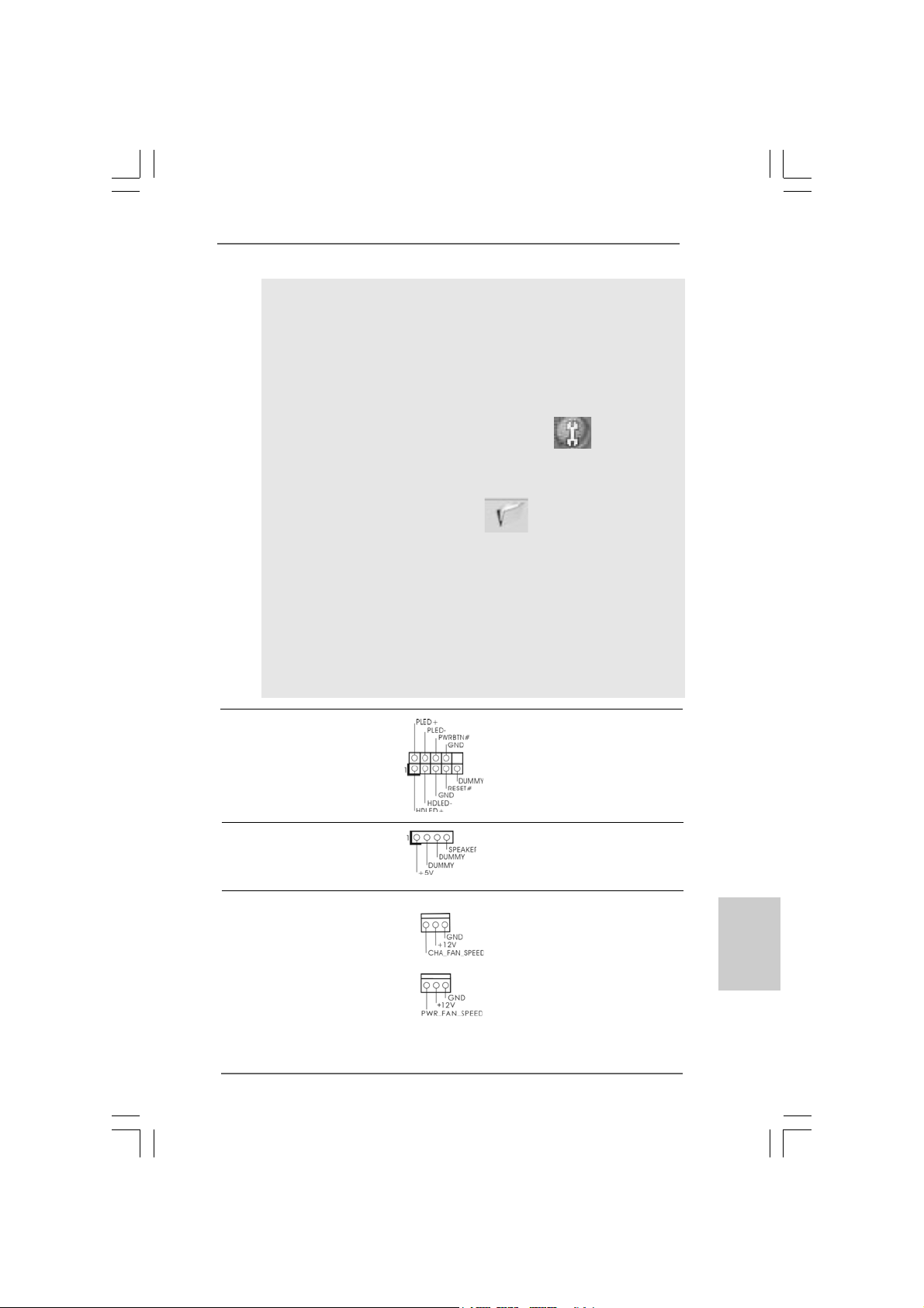
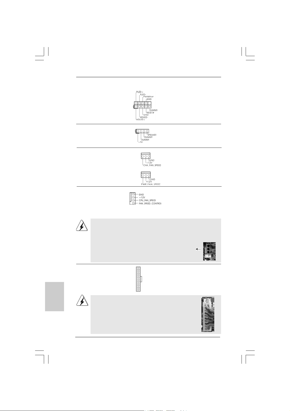
System Panel Header This header a ccommodates
(9-pin PANEL1) several system front pa nel
(see p.2 No. 15) functions.
Chassis Spea ker He ader Please connect the chassis
(4-pin SPEAKER 1) speaker to this hea der.
(see p.2 No. 14)
Chassis a nd Power Fa n Connectors Plea se conne ct the fan cables
(3-pin CHA_FAN1) to the fan connectors a nd
(see p.2 No. 17) match the black wire to the
ground pin.
(3-pin PWR_FAN1)
(see p.2 No. 30)
ASRock P31DE Motherboard
1717
17
1717
EnglishEnglish
EnglishEnglish
English
Page 18
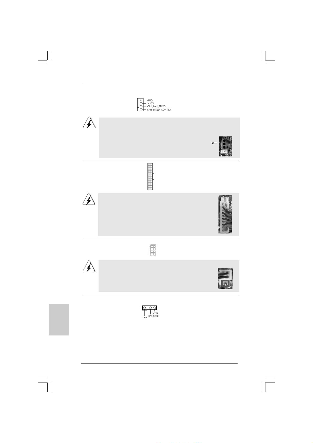
CPU Fan Connector Please connect a CPU fan ca ble
(4-pin CPU_FAN1) to this connector and match
(see p.2 No. 31) the black wire to the ground pin.
1
2
3
4
Though this motherboard provides 4-Pin CPU fan (Quiet Fan) support, the 3-Pin
CPU fan still can work successfully even without the fan speed control function.
If you plan to connect the 3-Pin CPU fan to the CPU fan connector on this
motherboard, please connect it to Pin 1-3.
Pin 1-3 Connected
3-Pin Fan Installation
12
ATX Power Conne ctor Please connect an A TX power
(24-pin ATXPWR1) supply to this connector.
(see p.2 No. 6)
24
1
13
English
EnglishEnglish
EnglishEnglish
Though this motherboard provides 24-pin ATX power connector,
12
24
it can still work if you adopt a traditional 20-pin ATX power supply.
To use the 20-pin ATX power supply, please plug your power
supply along with Pin 1 and Pin 13.
20-Pin ATX Power Supply Installation
ATX 12V Power Connector Please connect an A TX 12V
(8-pin ATX12V1) power supply to this connector.
(see p.2 No. 2)
5 1
8 4
1
13
Though this motherboard provides 8-pin ATX 12V power
connector, it can still work if you adopt a traditional 4-pin ATX
5 1
12V power supply. To use the 4-pin ATX power supply, please
plug your power supply along with Pin 1 and Pin 5.
4-Pin ATX 12V Power Supply Installation
8 4
HDMI_SPDIF Header HDMI_SPDIF header, providing
(3-pin HDMI_SPDIF1) SPDIF audio output to HDMI V GA
(see p.2 No. 24) card, allows the system to
connect HDMI Digital TV/
projector/LCD devices. Ple a se
connect the HDMI_SPDIF
connector of HDMI V GA card to
this header.
1818
18
1818
ASRock P31DE Motherboard
Page 19
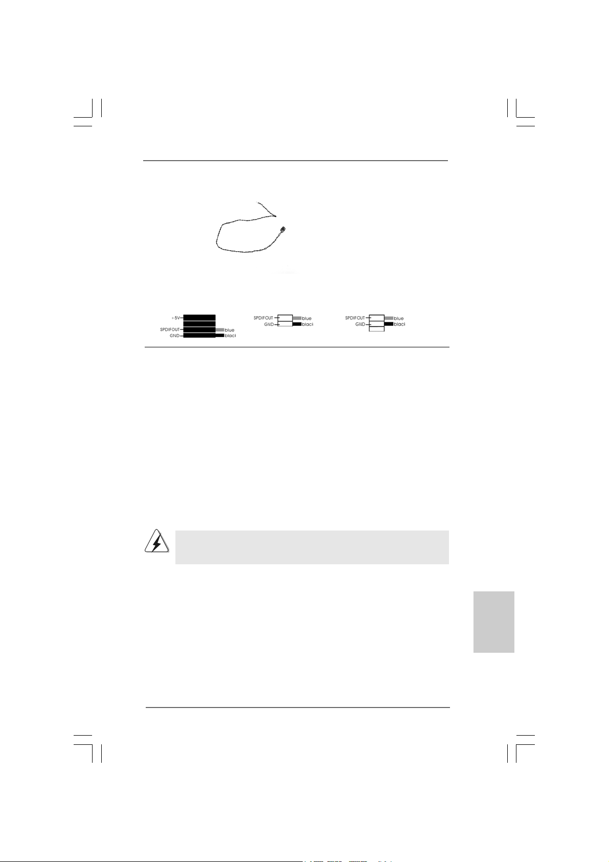
HDMI_SPDIF Cable Please connect the black end (A)
(Optional) of HDMI_SPDIF cable to the
C
B
A
HDMI_SPDIF header on the
motherboard. Then connect the
white end (B or C) of
HDMI_SPDIF cable to the
HDMI_SPDIF connector of HDMI
VGA card.
ation
12
n
1
5 1
8 4
A. black end B. white end (2-pin) C. white end (3-pin)
2.72.7
Driver Installation GuideDriver Installation Guide
2.7
Driver Installation Guide
2.72.7
Driver Installation GuideDriver Installation Guide
To install the drivers to your system, plea se insert the support CD to your optical drive
24
13
first. Then, the drivers compatible to your system ca n be auto-detected and listed on
the support CD driver page. Please follow the order from up to bottom side to install
those required drivers. Therefore, the drivers you install ca n work properly .
2.82.8
Untied Overclocking TUntied Overclocking T
2.8
Untied Overclocking T
2.82.8
Untied Overclocking TUntied Overclocking T
This motherboard supports Untied Overclocking Technology, which means during
overclocking, FSB enjoys better margin due to fixed PCI / PCIE buses. Before you
enable Untied Overclocking function, plea se enter “Overclock Mode” option of BIOS setup
to set the selection from [Auto] to [CPU, PCIE, Async.]. Therefore, CPU FSB is untied
during overclocking, but PCI / PCIE buses are in the fixed mode so that FSB can operate
under a more stable overclocking environment.
Please refer to the warning on page 7 for the possible overclocking risk
before you apply Untied Overclocking Technology.
echnologyechnology
echnology
echnologyechnology
ASRock P31DE Motherboard
1919
19
1919
EnglishEnglish
EnglishEnglish
English
Page 20

3. BIOS Information3. BIOS Information
3. BIOS Information
3. BIOS Information3. BIOS Information
The Flash Memory on the motherboard stores BIOS Setup Utility. When you start up
the computer, please press <F2> during the Power-On-Self-Test (POST) to enter
BIOS Setup utility; otherwise, POST continues with its test routines. If you wish to
enter BIOS Setup after POST, please restart the system by pressing <Ctl> + <Alt> +
<Delete>, or pressing the reset button on the system chassis. The BIOS Setup program is designed to be user-friendly. It is a menu-driven progra m, which allows you to
scroll through its various sub-menus and to select among the predetermined choices.
For the detailed information about BIOS Setup, please refer to the User Manual (PDF
file) contained in the Support CD.
English
EnglishEnglish
EnglishEnglish
4. Sof4. Sof
4. Sof
4. Sof4. Sof
This motherboard supports various Microsoft® Windows® operating systems: 2000 /
XP / XP 64-bit / VistaTM / Vista
contains necessary drivers and useful utilities that will enhance motherboard features.
To begin using the Support CD, insert the CD into your CD-ROM drive. It will display
the Main Menu automatically if “AUTORUN” is enabled in your computer. If the Main
Menu does not appear automatically, locate and double-click on the file “ASSETUP.
EXE” from the BIN folder in the Support CD to display the menus.
tware Supportware Suppor
tware Suppor
tware Supportware Suppor
TM
64-bit. The Support CD that ca me with the motherboard
t CD informationt CD information
t CD information
t CD informationt CD information
2020
20
2020
ASRock P31DE Motherboard
Page 21
1. Einführung1. Einführung
1. Einführung
1. Einführung1. Einführung
Wir danken Ihnen für den Kauf des ASRock P31DE Motherboard, ein zuverlässiges
Produkt, welches unter den ständigen, strengen Qualitätskontrollen von ASRock gefertigt
wurde. Es bietet Ihnen exzellente Leistung und robustes De sign, gemäß der V erpflichtung
von ASRock zu Qualität und Halbarkeit.
Diese Schnellinstallationsanleitung führt in das Motherboard und die schrittweise
Installation ein. Details über das Motherboard finden Sie in der
Bedienungsanleitung auf der Support-CD.
Da sich Motherboard-Spezifikationen und BIOS-Software verändern
können, kann der Inhalt dieses Handbuches ebenfalls jederzeit geändert
werden. Für den Fall, dass sich Änderungen an diesem Handbuch
ergeben, wird eine neue Version auf der ASRock-Website, ohne weitere
Ankündigung, verfügbar sein. Die neuesten Grafikkarten und unterstützten
CPUs sind auch auf der ASRock-Website aufgelistet.
ASRock-Website: http://www.asrock.com
Wenn Sie technische Unterstützung zu Ihrem Motherboard oder spezifische
Informationen zu Ihrem Modell benötigen, besuchen Sie bitte unsere
Webseite:
www.asrock.com/support/index.asp
1.1 Kartoninhalt
ASRock P31DE Motherboard
(ATX-Formfa ktor: 30.5 cm x 19.1 cm; 12.0 Zoll x 7.5 Zoll)
ASRock P31DE Schnellinstallationsanleitung
ASRock P31DE_ Support-CD
Ein 80-adriges Ultra-A T A 66/100 IDE-Fla chbandka bel
Ein Seriell-ATA- (SA T A) Datenka bel (Option)
Ein Seriell-ATA (SAT A) Festplattennetzka bel (Option)
Ein I/O Shield
ASRock P31DE Motherboard
2121
21
2121
DeutschDeutsch
DeutschDeutsch
Deutsch
Page 22
1.21.2
SpezifikationenSpezifikationen
1.2
Spezifikationen
1.21.2
SpezifikationenSpezifikationen
Deutsch
DeutschDeutsch
DeutschDeutsch
2222
22
2222
Plattform - ATX-Formfaktor: 30.5 cm x 19.1 cm; 12.0 Zoll x 7.5 Zoll
CPU - LGA 775 für Intel® CoreTM 2 Extreme / CoreTM 2 Quad / Core
2 Duo / Pentium® Dual Core / Celeron® Dual Core / Celeron
unterstützt Penryn Quad Core Yorkfield und Dual Core
Wolfdale Prozessoren
- Kompatibilität mit FSB1600/1333/1066/800 MHz
(siehe VORSICHT 1)
- Unterstützt Hyper-Threading-Technologie
(siehe VORSICHT 2)
- Unterstützt Untied-Übertaktungstechnologie
(siehe VORSICHT 3)
- Unterstützt EM64T -CPU
Chipsatz - Intel® G31 & ICH7
- Northbridge: Intel® G31/P31
- Southbridge: Intel® ICH7
Speicher - Unterstützung von Dual-Kan al-DDR2-Speichertechnologie
(siehe VORSICHT 4)
- 2 x Steckplätze für DDR2
- Unterstützt DDR2 1066/800/667 non-ECC, ungepufferter Speicher
(siehe VORSICHT 5)
- Max. Kapazität des Systemspeichers: 8GB
(siehe VORSICHT 6)
Erweiterungs- - 1 x PCI Express x16-Steckplätze
steckplätze - 2 x PCI Express x1-Steckplätze
- 3 x PCI -Steckplätze
Onboard-VGA - Intel® Graphics Media Accelerator 3100
- Pixel Shader 2.0, DX9.0 VGA
- Maximal gemeinsam genutzter Speicher 384MB
(siehe VORSICHT 7)
Audio - 5.1 CH Windows® VistaTM Premium Level HD Audio
(ALC662 Audio Codec)
LAN - PCIE x1 Gigabit LAN 10/100/1000 Mb/s
- Realtek RTL81 1 1DL
- Unterstützt W a ke-On-LAN
E/A-Anschlüsse I/O Panel
an der - 1 x PS/2 Mouse Port
Rückseite - 1 x PS/2 Keyboard Port
- 1 x Serieller port: COM 1
- 1 x VGA Port
- 4 x Ready-to-Use USB 2.0 Ports
ASRock P31DE Motherboard
TM
®
Page 23
- 1 x RJ-45 LAN Port mit LED (ACT/LINK LED und SPEED LED)
- Audioa n schlüsse: Line In / Line Out / Mikrofon
Anschlüsse - 4 x SATAII-Anschlüsse, unterstützt bis 3.0 Gb/s
Datenübertragungsrate (U nterstützt keine “RAID”- und “Hot Plug”-Funktionen) (siehe VORSICHT 8)
- 1 x ATA100 IDE-An schlüsse (U nterstützt bis 2 IDE-Geräte)
- 1 x F DD-Anschlüsse
- 1 x Infrarot-Modul-Header
- 1 x Druckerport-Anschlussleiste
- 1 x HDMI_SPDIF-Header
- CPU/Gehäuse/Stromlüfter-Anschluss
- 24-pin A TX-Netz-Header
- 8-pin anschluss für 12V -A TX-Netzte il
- Interne Audio-Anschlüsse
- Anschluss für Audio auf der Gehäusevorderseite
- 2 x USB 2.0 Buchse (unterstützt 4 USB 2.0 Ports)
(siehe VORSICHT 9)
BIOS - 4Mb AMI BIOS
- AMI legal BIOS mit U nterstützung für “Plug and Play”
- ACPI 1.1-Weckfunktionen
- JumperFree-Modus
- SMBIOS 2.3.1
- Zentraleinheit, VCCM Stromspa nnung Multia npa ssung
- Unterstützt Smart BIOS
Support-CD - Treiber, Dienstprogramme, Antivirussoftware
(Probeversion)
Einzigartige - ASRock OC Tuner (siehe VORSICHT 10)
Eigenschaft - Intelligent Energy Saver (Intelligente Energiesparfunktion)
(siehe VORSICHT 11)
- Sofortstart
- Hybrid Booster:
- Schrittloser CPU-Frequenz-Kontrolle
(siehe VORSICHT 12)
- ASRock U-COP (siehe VORSICHT 13)
- Boot Failure Guard (B.F.G. – Systemstartfehlerschutz)
Hardware Monitor - CPU-Temperatursen sor
- Motherboardtemperaturerkennung
- Drehza hlmessung für CPU/Gehäuse/Stromlüfter
- CPU-Lüftergeräuschdämpfung
- Spannungsüberwachung: +12V, +5V, +3.3V, Vcore
Betriebssysteme - Unterstützt Microsoft® Windows® 2000 / XP / XP 64-Bit /
VistaTM / Vista
ASRock P31DE Motherboard
TM
64-Bit
2323
23
2323
DeutschDeutsch
DeutschDeutsch
Deutsch
Page 24
Deutsch
DeutschDeutsch
DeutschDeutsch
Zertifizierungen - FCC, CE, WHQL
* Für die ausführliche Produktinformation, besuchen Sie bitte unsere Website:
http://www.asrock.com
WARNUNG
Beachten Sie bitte, dass Overclocking, einschließlich der Einstellung im BIOS, Anwenden
der Untied Overclocking-Technologie oder Verwenden von Overclocking-Werkzeugen von
Dritten, mit einem gewissen Risiko behaftet ist. Overclocking kann sich nachteilig auf die
Stabilität Ihres Systems auswirken oder sogar Komponenten und Geräte Ihres Systems
beschädigen. Es geschieht dann auf eigene Gefahr und auf Ihre Kosten. Wir übernehmen
keine Verantwortung für mögliche Schäden, die aufgrund von Overclocking verursacht
wurden.
VORSICHT!
1. FSB1600-CPU wird im Übertaktmodus laufen. In diesem Fall wird die
PCIE-Frequenz auf 120 MHz übertaktet.
2. Die Einstellung der “Hyper-Threading Technology”, finden Sie auf
Seite 32 des auf der Support-CD enthaltenen Benutzerhandbuches
beschrieben.
3. Dieses Motherboard unterstützt die Untied-Übertaktungstechnologie.
Unter “Entkoppelte Übertaktungstechnologie” auf Seite 19 finden Sie
detaillierte Informationen.
4. Dieses Motherboard unterstützt Dual-Kanal-Speichertechnologie. Vor
Implementierung der Dual-Kanal-Speichertechnologie müssen Sie
die Installationsanleitung für die Speichermodule auf Seite 12
zwecks richtiger Installation gelesen haben.
5. Die unterstützten Arbeitsspeicherfrequenzen und die entsprechende
CPU FSB-Frequenz entnehmen Sie bitte der nachstehenden Tabelle.
CPU FSB-Frequenz Unterstützte Arbeitsspeicherfrequenz
1600 DDR2 800, DDR2 1066 *
1333 DDR2 667, DDR2 800, DDR2 1066 *
1066 DDR2 667, DDR2 800, DDR2 1066
800 DDR2 667, DDR2 800
* Bei Verwendung einer FSB1600-CPU auf diesem Motherboard läuft
es mit DDR2 960, wenn Sie ein DDR2 1066-Speichermodul
verwenden. Bei Verwendung einer FSB1333-CPU auf diesem
Motherboard läuft es mit DDR2 1000, wenn Sie ein DDR2 1066-
Speichermodul verwenden.
* DDR2 1066 Speichermodule werden in Übertakten Modus
funktionieren.
6. Durch Betriebssystem-Einschränkungen kann die tatsächliche
Speichergröße weniger als 4 GB betragen, da unter Windows
Windows® Vista™ etwas Speicher zur Nutzung durch das System
reserviert wird. Unter Windows® XP 64-bit und Windows® Vista™ 64-bit
mit 64-Bit-CPU besteht diese Einschränkung nicht.
®
XP und
2424
24
2424
ASRock P31DE Motherboard
Page 25
7. Die Maximalspeichergröße ist von den Chipshändler definiert und
umgetauscht. Bitte überprüfen Sie Intel® website für die neuliche
Information.
8. Vor Installation der SATAII-Festplatte an den SATAII-Anschluss lesen
Sie bitte “Setup-Anleitung für SATAII-Festplatte” auf Seite 25 der
“Bedienungsanleitung” auf der Support-CD, um Ihre SATAII-Festplatte
dem SATAII-Modus anzugleichen. Sie können die SATA-Festplatte
auch direkt mit dem SATAII-Anschluss verbinden.
9. Das Power Management für USB 2.0 arbeitet unter Microsoft
Windows® VistaTM 64-Bit / VistaTM / XP 64-Bit / XP SP1 oder SP2/2000
SP4 einwandfrei.
10. Es ist ein benutzerfreundlicher ASRock Übertaktenswerkzeug, das
erlaubt, dass Sie Ihr System durch den Hardware-Monitor Funktion zu
überblicken und Ihre Hardware-Geräte übertakten, um die beste
Systemleistung unter der Windows® Umgebung zu erreichen.
Besuchen Sie bitte unsere Website für die Operationsverfahren von
ASRock OC Tuner. ASRock-Website: http://www.asrock.com
11. Mit einem fortschrittlichen, eigenständigen Hard- und Softwaredesign
nutzt der Intelligent Energy Saver eine revolutionäre Technologie, die
bisher unerreichte Energieeinsparungen ermöglicht. Mit anderen Worten:
Sie verbrauchen besonders wenig Energie und erreichen einen hohen
Wirkungsgrad, ohne dass dies zu Lasten der Rechenleistung geht. Auf
unseren Internetseiten finden Sie einige Erläuterungen zur
Funktionsweise des Intelligent Energy Saver.
ASRock-Website: http://www.asrock.com
12. Obwohl dieses Motherboard stufenlose Steuerung bietet, wird
Overclocking nicht empfohlen. Frequenzen, die von den empfohlenen
CPU-Busfrequenzen abweichen, können Instabilität des Systems
verursachen oder die CPU beschädigen.
13. Wird eine Überhitzung der CPU registriert, führt das System einen
automatischen Shutdown durch. Bevor Sie das System neu starten, prüfen
Sie bitte, ob der CPU-Lüfter am Motherboard richtig funktioniert, und
stecken Sie bitte den Stromkabelstecker aus und dann wieder ein. Um die
Wärmeableitung zu verbessern, bitte nicht vergessen, etwas
Wärmeleitpaste zwischen CPU und Kühl körper zu sprühen.
®
ASRock P31DE Motherboard
2525
25
2525
DeutschDeutsch
DeutschDeutsch
Deutsch
Page 26
1.3 Einstellung der Jumper1.3 Einstellung der Jumper
1.3 Einstellung der Jumper
1.3 Einstellung der Jumper1.3 Einstellung der Jumper
Die Abbildung verdeutlicht, wie Jumper
gesetzt werden. Werden Pins durch
Jumperkappen verdeckt, ist der Jumper
“Gebrückt”. Werden keine Pins durch
Jumperkappen verdeckt, ist der Jumper
“Offen”. Die Abbildung zeigt einen 3-Pin
Jumper dessen Pin1 und Pin2 “Gebrückt”
sind, bzw. es befindet sich eine JumperKappe auf diesen beiden Pins.
Jumper Einstellun Beschreibung
PS2_USB_PWR1 Überbrücken Sie Pin2, Pin3, um
(siehe S.2 - No. 1) +5VSB (Standby) zu setzen
Hinweis: Um +5VSB nutzen zu können, muss das Netzteil auf dieser Leitung 2A
oder mehr leisten können.
CMOS löschen
(CLRCMOS1, 2-Pin jumper)
(siehe S.2 - No. 8)
Hinweis: Mit CLRCMOS1 können Sie die Daten im CMOS löschen. Die CMOS Daten
beinhalten die Systeminformationen wie Systemkennwort, Datum, Zeit
und System-Setupeinstellungen. Um die Einstellungen zu löschen und
Default-Werte wiederherzustellen, schalten Sie den Computer aus,
ziehen Sie den Netzstecker und überbrücken Sie 2-pin von CLRCMOS1
mithilfe des Jumpers für 5 Sekunden.
2-Pin jumper
Gebrückt Offen
und die PS/2 oder USBWe ckfunktionen zu aktivieren.
Deutsch
DeutschDeutsch
DeutschDeutsch
2626
26
2626
ASRock P31DE Motherboard
Page 27
1.4 Integrierte Header und Anschlüsse1.4 Integrierte Header und Anschlüsse
1.4 Integrierte Header und Anschlüsse
1.4 Integrierte Header und Anschlüsse1.4 Integrierte Header und Anschlüsse
Integrierte Header und Anschlüsse sind KEINE Jumper. Setzen Sie
KEINE Jumperkappen auf diese Header und Anschlüsse. Wenn Sie
Jumperkappen auf Header und Anschlüsse setzen, wird das
Motherboard unreparierbar beschädigt!
Anschluss für das
Floppy-Laufwerk
(33-Pin FLOPPY1)
(siehe S.2 - No. 22)
die rotgestreifte Seite auf Stift 1
Hinweis: Achten Sie darauf, dass die rotgestreifte Seite des Ka bel mit der Stift 1-
Seite des An schlusses verbunden wird.
Primärer IDE-Anschluss (Blauer)
(39-pin IDE1, siehe S.2 - No. 7)
Blauer Anschluss Schwarzer Anschluss
zum Motherboard zur Festplatte
80-adriges ATA 66/100 Kabel
Hinweis: Details entnehmen Sie bitte den Anweisungen Ihres IDE-Gerätehändlers.
Seriell-ATAII-Anschlüsse Diese vier Serial ATA
(SATAII_1: siehe S.2, Punkt 13) (SAT A II) -An schlüsse
(SATAII_2: siehe S.2, Punkt 12) unterstützen interne SAT A-
(SATAII_3: siehe S.2, Punkt 10) oder SAT A II-Festplatten. Die
(SATAII_4: siehe S.2, Punkt 11) aktuelle SAT AII-Schnittstelle
SATAII_3
SATAII_4
ermöglicht eine
SATAII_1
Datenübertragungsrate bis
SATAII_2
3,0 Gb/s.
Serial A TA- (SATA-) Sie können beide Enden des
Datenkabel SATA-Datenkabels entweder
(Option) mit der SATA / SAT AII-
Festplatte oder
dem SATAII-Anschluss am
Mainboard verbinden.
ASRock P31DE Motherboard
2727
27
2727
DeutschDeutsch
DeutschDeutsch
Deutsch
Page 28
Serial AT A- (SAT A-) Verbinden Sie bitte da s
Stromversorgungskabel schwarze Ende des SA TA(Option) Stromversorgungskabels mit
SATA-HDD-Stromanschluss
Verbindung zum
Verbindung zum
Netzteil
dem Stromanschluss jedes
Laufwerks. Verbinden Sie
dann da s we iße Ende de s
SATA-tromversorgungskabels
mit dem Stromanschluss des
Netzteils.
USB 2.0-Header Zusätzlich zu den vier
(9-pol. USB6_7) üblichen USB 2.0-Ports an den
(siehe S.2 - No. 18) I/O-Anschlüssen befinden sich
zwei USB 2.0-Anschlussleisten
am Motherboard. Pro USB 2.0 Anschlussleiste werden zwei
(9-pol. USB4_5) USB 2.0-Ports unterstützt.
(siehe S.2 - No. 19)
Infrarot-Modul-Header Dieser Header unterstützt ein
(5-pin IR1) optionales, drahtloses Sende-
(siehe S.2 - No. 20) und Empfangs-Infrarotmodul.
Deutsch
DeutschDeutsch
DeutschDeutsch
2828
28
2828
Druckerport-Anschlussleiste Dies ist eine Schnittstelle zum
(25-pol. LPT1) Anschluss eines Druckerport-
(siehe S.2 - No. 21) Kabels, mit dem Sie passende
Drucker auf einfache Weise
anschließen können.
Interne Audio-Anschlüsse Diese ermöglichen Ihnen
(4-Pin CD1) Stereo-Signalquellen, wie z. B.
(CD1: siehe S.2 - No. 25) CD-ROM, DV D-ROM, TV-Tuner
CD1
oder MPEG-Karten mit Ihrem
System zu verbinden.
ASRock P31DE Motherboard
Page 29
Anschluss für Audio auf Dieses Interface zu eine m
der Gehäusevorderseite Audio-Panel auf der Vorderseite
(9-Pin HD_AUDIO1) Ihres Gehäuses, ermöglicht
(siehe S.2 - No. 23) Ihnen eine bequeme
Anschlussmöglichkeit und
Kontrolle über Audio-Geräte.
1. High Definition Audio unterstützt Jack Sensing (automatische Erkennung
falsch angeschlossener Geräte), wobei jedoch die Bildschirmverdrahtung
am Gehäuse HDA unterstützen muss, um richtig zu funktionieren.
Beachten Sie bei der Installation im System die Anweisungen in unserem
Handbuch und im Gehäusehandbuch.
2. Wenn Sie die AC’97-Audioleiste verwenden, installieren Sie diese wie
nachstehend beschrieben an der Front-Audioanschlussleiste:
A. Schließen Sie Mic_IN (MIC) an MIC2_L an.
B. Schließen Sie Audio_R (RIN) an OUT2_R und Audio_L (LIN) an
OUT2_L an.
C. Schließen Sie Ground (GND) an Ground (GND) an.
D. MIC_RET und OUT_RET sind nur für den HD-Audioanschluss gedacht.
Diese Anschlüsse müssen nicht an die AC’97-Audioleiste
angeschlossen werden.
E. Rufen Sie das BIOS-Setup-Dienstprogramm auf. Wechseln Sie zu
Erweiterte Einstellungen und wählen Sie Chipset-Konfiguration. Setzen
Sie die Option Frontleistenkontrolle von [Automatisch] auf [Aktiviert].
F. Rufen Sie das Windows-System auf. Klicken Sie auf das Symbol in der
Taskleiste unten rechts, um den Realtek HD Audio-Manager aufzurufen.
Für Windows® 2000 / XP / XP 64-Bit Betriebssystem:
Klicken Sie auf “Audio-E/A”, wählen Sie die “Anschlusseinstellungen”
, wählen Sie “Erkennung der Frontleistenbuchse deaktivieren”
und speichern Sie die Änderung durch Klicken auf “OK”.
Für Windows® Vista
Die Rechtoberseite „Dateiordner“ Ikone anklicken ,
„Schalttafel Buchse Entdeckung sperren“ wählen und die Änderung
speichern, indem Sie „OKAY“ klicken.
G. Aktivierung des vorderseitigen Mikrofons.
Für Betriebssystem Windows® 2000 / XP / XP 64-Bit:
Wählen Sie “Front Mic” (Vorderes Mikr.) als Standard-Aufnahmegerät.
Möchten Sie Ihre Stimme über das vorderseitige Mikrofon hören, dann
wählen Sie bitte das Symbol “Mute” (Stumm) unter “Front Mic”
(Vorderes Mikr.) im Abschnitt “Playback” (Wiedergabe) ab.
Für Betriebssystem Windows® Vista
Rufen Sie die Registerkarte “Front Mic” (Vorderes Mikr.) im Realtek Bedienfeld auf. Klicken Sie auf “Set Default Device” (Standardgerät
einstellen), um das vorderseitige Mikrofon als Standard Aufnahmegerät zu übernehmen.
TM
/ VistaTM 64-Bit Betriebssystem:
TM
/ VistaTM 64-Bit:
ASRock P31DE Motherboard
2929
29
2929
DeutschDeutsch
DeutschDeutsch
Deutsch
Page 30
System Panel-He ader Dieser Header unterstützt
(9-pin PANEL1) mehrere Funktion der
(siehe S.2 - No. 15) Systemvorderseite.
Gehäuselautsprecher-Header Schließen Sie den
(4-pin SPEAKER1) Gehäuselautsprecher an
(siehe S.2 - No. 14) diesen Header an.
Gehäuse- und Stromlüfteranschlüsse Verbinden Sie die Lüfterka bel
(3-pin CHA_FAN1) mit den Lüfteranschlüssen,
(siehe S.2, No. 17) wobei der schwarze Dra ht a n
den Schutzleiterstift
(3-pin PWR_FAN1) angeschlossenwird.
(siehe S.2, No. 30)
Deutsch
DeutschDeutsch
DeutschDeutsch
3030
30
3030
CPU-Lüfteranschluss Verbinden Sie das CPU -
(4-pin CPU_FAN1) Lüfterkabel mit diesem
(siehe S.2 - No. 31) Anschluss und passen Sie den
1
2
3
4
schwarzen Draht dem
Erdungsstift an.
Obwohl dieses Motherboard einen vierpoligen CPU-Lüfteranschluss (Quiet
Fan) bietet, können auch CPU-Lüfter mit dreipoligem Anschluss
angeschlossen werden; auch ohne Geschwindigkeitsregulierung. Wenn Sie
einen dreipoligen CPU-Lüfter an den CPU-Lüferanschluss dieses
Motherboards anschließen möchten, verbinden Sie ihn bitte mit
den Pins 1 – 3.
Pins 1–3 anschließen
Lüfter mit dreipoligem Anschluss installieren
ATX-Netz-Hea der Verbinden Sie die ATX-
(24-pin ATXPWR1) Stromversorgung mit diesem
(siehe S.2 - No. 6) Header.
Obwohl dieses Motherboard einen 24-pol. ATX-Stromanschluss
12 124
13
12
24
bietet, kann es auch mit einem modifizierten traditionellen 20-pol.
ATX-Netzteil verwendet werden. Um e in 20-pol. ATX-Netzteil zu
verwenden, stecken Sie den Stecker mit Pin 1 und Pin 13 ein.
Installation eines 20-pol. ATX-Netzteils
1
13
ASRock P31DE Motherboard
Page 31

ATX 12V Anschluss Bitte schließen Sie an diesen
(8-pin ATX12V1) Anschluss die ATX 12V
(siehe S.2 - No. 2) Stromversorgung an.
Obwohl diese Hauptplatine 8-Pin ATX 12V Stromanschluss zur Verfügung
stellt, kann sie noch arbeiten, wenn Sie einen traditionellen 4-Pin ATX 12V
Energieversorgung adoptieren. Um die 4-Pin ATX Energieversorgung zu
verwenden, stecken Sie bitte Ihre Energieversorgung
zusammen mit dem Pin 1 und Pin 5 ein.
5 1
8 4
5 1
eren
Installation der 4-Pin ATX 12V Energieversorgung
8 4
HDMI_SPDIF-Anschluss Der HDMI_SPDIF-Anschluss
(HDMI_SPDIF1, dreipolig) stellt einen SPDIF-
(siehe S.2 - No. 24) Audioausgang für eine HDMI-
VGA-Karte zur V erfügung und
ermöglicht den Anschluss von
HDMI-Digitalgeräten wie
Fernsehgeräten, Projektoren,
LCD-Geräten an da s Syste m.
Bitte verbinden Sie den
HDMI_SPDIF-Anschluss der
HDMI-VGA-Karte mit diese m
Anschluss.
HDMI_SPDIF-Kabel Bitte verbinden Sie das
(Option) schwarze Ende (A) des
C
B
A
HDMI_SPDIF-Kabels mit dem
HDMI_SPDIF-Anschluss am
Motherboard. Schließen Sie
dann da s weiße Ende (B oder
C) des HDMI_SPDIF-Kabels an
den HDMI_SPDIF-Anschluss der
HDMI-VGA-Karte a n.
A. Schwarzes Ende B. Weißes Ende (zweipolig) C. Weißes Ende (dreipolig)
12
ils
1
24
13
3131
31
3131
DeutschDeutsch
DeutschDeutsch
Deutsch
ASRock P31DE Motherboard
Page 32

2. BIOS-Information2. BIOS-Information
2. BIOS-Information
2. BIOS-Information2. BIOS-Information
Das Flash Memory dieses Motherboards speichert das Setup-Utility. Drücken Sie
<F2> während des POST (Power-On-Self-Test) um ins Setup zu gela ngen, ansonsten
werden die Testroutinen weiter abgearbeitet. Wenn Sie ins Setup gelangen wollen,
nachdem der POST durchgeführt wurde, müssen Sie das System über die
Tastenkombination <Ctrl> + <Alt> + <Delete> oder den Reset-Knopf auf der
Gehäusevorderseite, neu starten. Natürlich können Sie einen Neustart auch
durchführen, indem Sie das System kurz ab- und danach wieder anschalten.
Das Setup-Programm ist für eine bequeme Bedienung entwickelt worden. Es ist
ein menügesteuertes Programm, in dem Sie durch unterschiedliche Untermenüs
scrollen und die vorab festgelegten Optionen auswählen können. Für detaillierte
Informationen zum BIOS-Setup, siehe bitte das Benutzerhandbuch (PDF Datei) auf
der Support CD.
3. Software Support CD information3. Software Support CD information
3. Software Support CD information
3. Software Support CD information3. Software Support CD information
Dieses Motherboard unterstützt eine Reiche von Microsoft® Windows
Betriebssystemen: 2000 / XP / XP 64-Bit / VistaTM / Vista
Motherboard beigefügte Support-CD enthält hilfreiche Software, Treiber und
Hilfsprogramme, mit denen Sie die Funktionen Ihres Motherboards verbessern
können Legen Sie die Support-CD zunächst in Ihr CD-ROM-Laufwerk ein. Der
Willkommensbildschirm mit den Installationsmenüs der CD wird automatisch
aufgerufen, wenn Sie die “Autorun”-Funktion Ihres Systems aktiviert haben.
Erscheint der Wilkommensbildschirm nicht, so “doppelklicken” Sie bitte auf das File
ASSETUP.EXE im BIN-Verzeichnis der Support-CD, um die Menüs aufzurufen.
Das Setup-Progra mm soll es Ihnen so le icht wie möglich ma chen. Es ist menügesteuert,
d.h. Sie können in den verschiedenen Untermenüs Ihre Auswahl treffen und die
Programme werden dann automatisch installiert.
TM
64-Bit. Die Ihrem
®
Deutsch
DeutschDeutsch
DeutschDeutsch
3232
32
3232
ASRock P31DE Motherboard
Page 33

1. Introduction1. Introduction
1. Introduction
1. Introduction1. Introduction
Merci pour votre achat d’une carte mère ASRock P31DE, une carte mère très fiable
produite selon les critères de qualité rigoureux de ASRock. Elle of fre des perf orma nces
excellentes et une conception robuste conformément à l’engagement d’ASRock sur la
qualité et la fiabilité au long terme.
Ce Guide d’installation rapide présente la carte mère et constitue un guide
d’installation pas à pas. Des informations plus détaillées concernant la carte mère
pourront être trouvées dans le manuel l’utilisateur qui se trouve sur le CD
d’assistance.
Les spécifications de la carte mère et le BIOS ayant pu être mis à
jour, •le contenu de ce manuel est sujet à des changements sans
notification. Au cas où n’importe qu’elle modification intervenait sur ce
manuel, la version mise à jour serait disponible sur le site web
ASRock sans nouvel avis. Vous trouverez les listes de prise en
charge des cartes VGA et CPU également sur le site Web ASRock.
Site web ASRock, http://www.asrock.com
Si vous avez besoin de support technique en relation avec cette carte
mère, veuillez consulter notre site Web pour de plus amples
informations particulières au modèle que vous utilisez.
www.asrock.com/support/index.asp
1.1 Contenu du paquet
Carte mère ASRock P31DE
(Facteur de forme ATX : 12.0 pouce s x 7.5 pouce s, 30.5 cm x 19.1 cm)
Guide d’installation rapide ASRock P31DE
CD de soutien ASRock P31DE
Un câble ruba n IDE Ultra ATA 66/100 80 conducteurs
Un câble de données Seri al ATA (SA T A) (en option)
Un cordon d’alimentation DD série AT A (SA TA) (en option)
Un écran I/O
ASRock P31DE Motherboard
3333
33
3333
çaisçais
çaisçais
çais
ranran
ranran
ran
FF
FF
F
Page 34

F
FF
FF
rançais
rançaisrançais
rançaisrançais
3434
34
3434
1.21.2
SpécificationsSpécifications
1.2
Spécifications
1.21.2
SpécificationsSpécifications
Format - Facteur de forme ATX :
12.0 pouces x 7.5 pouces, 30.5 cm x 19.1 cm
CPU - LGA 775 pour Intel® CoreTM 2 Extreme / CoreTM 2 Quad /
Chipsets - Intel® G31 & ICH7
Mémoire - Compatible avec la Technologie de Mémoire à Ca nal Double
Slot d’extension - 1 x slot PCI Express x16
VGA sur carte - Intel® Graphics Media Accelerator 3100
Audio - 5.1 Son haute définition de première qualité CH Windows
LAN - PCIE x1 Gigabit LAN 10/100/1000 Mb/s
Panneau arrière I/O Panel
E/S - 1 x port souris PS/2
TM
Core
2 Duo / Pentium® Dual Core / Celeron® Dual Core /
Celeron® acceptant les processeurs Penryn Quad Core
Y orkfield et Dual Core Wolfdale
- Compatible avec tous FSB1600/1333/1066/800MHz CPUs
(voir A TTENTION 1)
- Prise en charge de la technologie Hyper-Threading
(voir ATTENTION 2)
- Prend en charge la technologie Untied Overclocking
(voir ATTENTION 3)
- Prise en charge de la technologie EM64T par le CPU
- Northbridge: Intel® G31/P31
- Southbridge: Intel® ICH7
(voir ATTENTION 4)
- 2 x slots DIMM DDR2
- Supporte DDR2 1066/800/667 non-ECC, sa n s a mortissement
mémoire (voir ATTENTION 5)
- Capacité maxi de mémoire système: 8GB
(voir ATTENTION 6)
- 2 x slots PCI Express x1
- 3 x slots PCI
- nuanceur de pixels 2.0, VGA DX9.0
- mémoire partagée max 384MB (voir ATTENTION 7)
VistaTM (codec audio ALC662)
- Realtek RTL81 1 1DL
- Support du Wa ke-On-LAN
- 1 x port clavier PS/2
- 1 x port série: COM 1
- 1 x port VGA
- 4 x ports USB 2.0 par défaut
ASRock P31DE Motherboard
®
Page 35

- 1 x port LAN RJ-45 avec LED (ACT/LED CLIGNOTANTE et
LED VITESSE)
- Jack audio: entrée ligne / sortie ligne / microphone
Connecteurs - 4 x connecteurs SAT AII, prennent en charge un taux de
transfert de donnée s pouva nt aller jusqu’à 3.0Go/s
(Ne supporte pas les f onction s “RAID” et “Hot-Plug”
(Connexion à chaud)) (voir ATTENTION 8)
- 1 x ATA100 IDE connecteurs
(prend en charge jusqu’à 2 périphériques IDE)
- 1 x Port Dis quette
- 1 x En-tête du module infrarouge
- 1 x embase de port d’impression
- 1 x Connecteur HDMI_SPDIF
- Connecteur pour ventilateur de CPU/Châssis/Ventilateur
- br. 24 connecteur d’ali mentation ATX
- br. 8 connecteur d’alimentation 12V ATX
- Connecteurs audio internes
- Connecteur audio panneau ava nt
- 2 x en-tête USB 2.0 (accepte 4 ports USB 2.0)
(voir ATTENTION 9)
BIOS - 4Mb BIOS AMI
- BIOS AMI
- Support du “Plug and Play”
- Compatible pour événements de réveil ACPI 1.1
- Gestion jumperless
- Support SMBIOS 2.3.1
- CPU, VCCM Tension Multi-a justement
- Prise en charge du Smart BIOS
CD d’assistance - Pilotes, utilitaires, logiciel anti-virus (Version d’essai)
Caractéristique - T uner ASRock OC (voir ATTENTION 10)
unique - Économiseur d’énergie intelligent (voir ATTENTION 11)
- l'Instant Boot
- L’accélérateur hybride:
- Contrôle direct de la fréquence CPU
(voir ATTENTION 12)
- ASRock U-COP (voir ATTENTION 13)
- Garde d’échec au démarrage (B.F.G.)
Surveillance - Contrôle de la température CPU
système - Mesure de température de la carte mère
- T a chéomètre ventilateur CPU/Châssis/V entilateur
- V entilateur silencieux d’unité centrale
- Monitoring de la tension: +12V, +5V, +3.3V, Vcore
ASRock P31DE Motherboard
3535
35
3535
çaisçais
çaisçais
çais
ranran
ranran
ran
FF
FF
F
Page 36

F
FF
FF
rançais
rançaisrançais
rançaisrançais
OS - Microsoft® Windows® 2000 / XP / XP 64-bit / VistaTM / Vista
64-bit
Certifications - FCC, CE, WHQL
* Pour de plus amples informations sur les produits, s’il vous plaît visitez notre site web:
http://www.asrock.com
A TTENTION
Il est important que vous réalisiez qu’il y a un certain risque à effectuer l’overclocking, y
compris ajuster les réglages du BIOS, appliquer la technologie Untied Overclocking, ou
utiliser des outils de tiers pour l’overclocking. L’overclocking peut affecter la stabilité de
votre système, ou même causer des dommages aux composants et dispositifs de votre
système. Si vous le faites, c’est à vos frais et vos propres risques. Nous ne sommes
pas responsables des dommages possibles causés par l’overclocking.
ATTENTION!
1. Le CPU FSB1600 fonctionne en mode overclockage. Dans cette
situation, la fréquence PCIE est également overclockée à 120MHz.
2. En ce qui concerne le paramétrage “Hyper-Threading Technology”,
veuillez consulter la page 32 du manuel de l’utilisateur sur le CD
technique.
3. Cette carte mère prend en charge la technologie Untied Overclocking.
Veuillez lire “La technologie de surcadençage à la volée” à la page 19
pour plus d’informations.
4. Cette carte mère supporte la Technologie de Mémoire à Canal
Double. Avant d’intégrer la Technologie de Mémoire à Canal Double,
assurez-vous de bien lire le guide d’installation des modules
mémoire en page 12 pour réaliser une installation correcte.
5. Veuillez vérifier dans le tableau ci-dessous pour les fréquences de
prise en charge mémoire et les fréquences FSB UC
correspondantes.
Fréquence FSB UC Fréquence de prise en charge mémoire
1600 DDR2 800, DDR2 1066 *
1333 DDR2 667, DDR2 800, DDR2 1066 *
1066 DDR2 667, DDR2 800, DDR2 1066
800 DDR2 667, DDR2 800
* Lorsque vous utilisez un processeur à FSB1600 sur cette carte
mère, le système fonctionnera à DDR2 960 si vous utilisez un
module mémoire DDR2 1066. Lorsque vous utilisez un processeur
à FSB1333 sur cette carte mère, le système fonctionnera à DDR2
1000 si vous utilisez un module mémoire DDR2 1066.
* DDR2 1066 module de mémoire fonctionneront en mode
overclocking.
6. Du fait des limites du système d’exploitation, la taille mémoire réelle
réservée au système pourra être inférieure à 4 Go sous Windows® XP
et Windows® VistaTM. Avec Windows® XP 64 bits et Windows® VistaTM 64
bits avec CPU 64 bits, il n’y a pas ce genre de limitation.
TM
3636
36
3636
ASRock P31DE Motherboard
Page 37

7. La dimension maximum du memoire partage est definie par le vendeur
de jeu de puces et est sujet de changer. Veuillez verifier la Intel® website
pour les informations recentes SVP.
8. Avant d’installer le disque dur SATAII au connecteur SATAII, veuillez
lire le Guide « Installation du disque dur SATAII » à la page 25 du
« Manuel de l’utilisateur » qui se trouve sur le CD de support pour
régler votre lecteur de disque dur SATAII au mode SATAII. Vous pouvez
aussi directement connecter le disque dur SATA au connecteur
SATAII.
9. La gestion de l’alimentation pour l’USB 2.0 fonctionne bien sous
Microsoft® Windows® VistaTM 64-bit/ VistaTM / XP 64-bit / XP SP1; SP2/
2000 SP4.
10. Il s’agit d’un usage facile ASRock overclocking outil qui vous permet
de surveiller votre système en fonction de la monitrice de matériel et
overclocker vos périphériques de matériels pour obtenir les
meilleures performances du système sous environnement
Windows®. S’il vous plaît visitez notre site web pour le
fonctionnement des procédures de Tuner ASRock OC.
ASRock website: http://www.asrock.com
11. Comprenant une conception matérielle et logicielle propriétaire
avancée, Intelligent Energy Saver est une technologie révolutionnaire
qui offre des gains d’énergie incomparables. En d’autres termes, il
est capable d’apporter des économies d’énergie exceptionnelles et
d’améliorer l’efficacité énergétique sans sacrifier aux performances
de calcul. Veuillez visiter notre site Web pour les procédures
d’utilisation d’Intelligent Energy Saver.
Site Web ASRock : http://www.asrock.com
12. Même si cette carte mère offre un contrôle sans souci, il n’est pas
recommandé d’y appliquer un over clocking. Des fréquences de bus CPU
autres que celles recommandées risquent de rendre le système instable
ou d’endommager le CPU et la carte mère.
13. Lorsqu’une surchauffe du CPU est détectée, le système s’arrête
automatiquement. Avant de redémarrer le système, veuillez vérifier que
le ventilateur d’UC sur la carte mère fonctionne correctement et débranchez
le cordon d’alimentation, puis rebranchez-le. Pour améliorer la dissipation
de la chaleur, n’oubliez pas de mettre de la pâte thermique entre le CPU le
dissipateur lors de l’installation du PC.
ASRock P31DE Motherboard
3737
37
3737
çaisçais
çaisçais
çais
ranran
ranran
ran
FF
FF
F
Page 38

1.3 Réglage des cavaliers1.3 Réglage des cavaliers
1.3 Réglage des cavaliers
1.3 Réglage des cavaliers1.3 Réglage des cavaliers
L’illustration explique le réglage des cavaliers.
Quand un ca puchon e st placé sur les broches, le
cavalier est « FERME ». Si aucun capuchon ne
relie les broches,le cavalier est « OUVERT ».
L’illustration montre un cavalier à 3 broches dont
les broches 1 et 2 sont “FERMEES” quand le
capuchon est placé sur ces 2 broches.
Le cavalier Description
PS2_USB_PWR1 Court-circuitez les broches 2
(voir p.2 No. 1) et 3 pour choisir +5VSB
Note: Pour sélectionner +5VSB, il faut obligatoirement 2 Amp et un courant standby
supérieur fourni par l’alimentation.
Effacer la CMOS
(CLRCMOS1,
le cavalier à 2 broches)
(voir p.2 No. 8)
Note: CLRCMOS1 vous permet d’effacer les données de la CMOS. Ces données
incluent les informations système telles que le mot de passe, la date, l’heure,
et les paramètres du système. Pour restaurer les paramètres système à leur
valeur par défaut, éteignez l’ordinateur et débranchez le câble d’alimentation.
Puis placez un cavalier sur les pins CLRCMOS1 pendant 5 secondes.
N’oubliez pas de retirer le cavalier ava nt après avoir restauré le CMOS.
le cavalier à 2 broches
Ferme Ouvert
(standby) et permettre aux
périphériques PS/2 ou USB de
réveiller le système.
F
FF
FF
rançais
rançaisrançais
rançaisrançais
3838
38
3838
ASRock P31DE Motherboard
Page 39

1.4 En-têtes et Connecteurs sur Carte1.4 En-têtes et Connecteurs sur Carte
1.4 En-têtes et Connecteurs sur Carte
1.4 En-têtes et Connecteurs sur Carte1.4 En-têtes et Connecteurs sur Carte
Les en-têtes et connecteurs sur carte NE SONT PAS des cavaliers.
NE PAS placer les capuchons de cavalier sur ces en-têtes et
connecteurs. Le fait de placer les capuchons de cavalier sur les entêtes et connecteurs causera à la carte mère des dommages
irréversibles!
Connecteur du lecteur
de disquette
(FLOPPY1 br. 33)
(voir p.2 No. 22)
Note: Assurez-vous que le côté avec fil rouge du câble est bien branché sur le
côté Broche1 du connecteur.
Connecteur IDE primaire (Bleu)
(IDE1 br. 39, voir p.2 No. 7)
connecteur bleu connecteur noir
vers la carte mère vers le disque dur
le côté avec fil rouge côté Broche1
Câble ATA 66/100 80 conducteurs
Note: Veuillez vous reporter aux instructions du fabricant de votre IDE périphérique
pour les détails.
Connecteurs Série ATAII Ces quatre connecteurs
(SATAII_1: voir p.2 fig. 13) Serial AT A (SA TAII) prennent
(SATAII_2: voir p.2 fig. 12) en charge les disques durs
(SATAII_3: voir p.2 fig. 10) SATA ou SATAII pour le s
(SATAII_4: voir p.2 fig. 11) dispositifs de stockage
Câble de données L’une des deux extrémités du
Série ATA (SATA) câble de données SATA peut
(en option) être connectée au disque dur
SATAII_3
SATAII_1
ASRock P31DE Motherboard
SATAII_4
SATAII_2
interne. L’interface SATAII
actuelle permet des taux
transferts de données
pouvant aller jusqu’à 3,0
Go/s.
SATA / SATAIIou au
connecteur SA TAII sur la carte
mère.
3939
39
3939
çaisçais
çaisçais
çais
ranran
ranran
ran
FF
FF
F
Page 40

Cordon d’alimentation Veuillez connecter l’extrémité
Série AT A (SA TA) noire du cordon d’alimentation
(en option) SATA sur le conne cteur
connecter au connecteur
d’alimentation du disque
dur SAT A
connecter à l’unité
d’alimentation
électrique
d’alimentation sur chaque unité.
Connectez ensuite l’extrémité
blanche du cordon d’alimentation
SATA sur le conne cteur
d’alimentation de l’unité
d’alimentation électrique.
En-tête USB 2.0 A côté des quatre ports USB
(USB6_7 br.9) 2.0 par défaut sur le panneau
(voir p.2 No. 18) E/S, il y a deux embases USB
2.0 sur cette carte mère.
(USB4_5 br.9) Chaque embase USB 2.0 peut
(voir p.2 No. 19) prendre en charge 2 ports USB
2.0.
En-tête du module infrarouge Cet en-tête supporte un module
(IR1 br.5) infrarouge optionnel de
(voir p.2 No. 20) transfert et de réception sa ns
fil.
F
FF
FF
rançais
rançaisrançais
rançaisrançais
4040
40
4040
Embase de port d’impression AIl s’agit d’une interface pour le
(LPT1 25 broches) câble du port d’impression, qui
(voir p.2 No. 21) permet le raccordement
pratique de périphériques
d’impression.
Connecteurs audio internes Ils vous permettent de gérer des
(CD1 br. 4) entrées audio à partir de sources
(CD1: voir p.2 No. 25) stéréo comme un CD-ROM,
CD1
DVD-ROM, un tuner TV ou une
carte MPEG.
ASRock P31DE Motherboard
Page 41

Connecteur audio panneau C’est une interface pour un câble
av ant audio en façade qui permet le
(HD_AUDIO1 br. 9) branchement et le contrôle
(voir p.2 No. 23) commodes de périphériques
audio.
1. L’audio à haute définition (HDA) prend en charge la détection de fiche,
mais le fil de panneau sur le châssis doit prendre en charge le HDA pour
fonctionner correctement. Veuillez suivre les instructions dans notre
manuel et le manuel de châssis afin installer votre système.
2. Si vous utilisez le panneau audio AC’97, installez-le sur l’adaptateur audio
du panneau avant conformément à la procédure ci-dessous :
A. Connectez Mic_IN (MIC) à MIC2_L.
B. Connectez Audio_R (RIN) à OUT2_R et Audio_L (LIN) à OUT2_L.
C. Connectez Ground (GND) à Ground (GND).
D. MIC_RET et OUT_RET sont réservés au panneau audio HD. Vous
n’avez pas besoin de les connecter pour le panneau audio AC’97.
E. Entrer dans l’utilitaire de configuration du BIOS. Saisir les Paramètres
avancés puis sélectionner Configuration du jeu de puces. Définir
l’option panneau de commande de [Auto] à [Activé].
F. Entrer dans le système Windows. Cliquer sur l’icône sur la barre de
tâches dans le coin inférieur droite pour entrer dans le Gestionnaire
audio Realtek HD.
Pour Windows® 2000 / XP / XP 64-bit OS:
Cliquer sur « E/S audio», sélectionner « Paramètres du connecteur »
, choisir « Désactiver la détection de la prise du panneau de
commande » et sauvegarder les changements en cliquant sur « OK ».
Pour Windows® VistaTM / VistaTM 64-bit OS:
Cliquer droit “Fichier” icone , selectionner” la detection
incapable de jack de panel d’avant “ et sauvegarder le changement par
cliquer”ok”.
G. Pour activer le mic.
Pour les SE Windows
Veuillez sélectionner “Front Mic” ( Mic. Avant) comme le dispositif
d’enregistrement par défaut.
Si vous voulez entendre votre voix à travers le mic. avant veuillez
désactiver l’icône «Silence» dans “Front Mic” ( Mic. Avant) de la portion
“Playback” (Lecture).
Pour les SE Windows® VistaTM / VistaTM 64 bits :
Allez à l’onglet «Front Mic» ( Mic. Avant) dans le panneau de
commandes Realtek.
Cliquez sur «Configurer le dispositif par défaut» pour faire du Mic Avant
le dispositif d’enregistrement par défaut.
®
2000 / XP / XP 64 bits :
ASRock P31DE Motherboard
4141
41
4141
çaisçais
çaisçais
çais
ranran
ranran
ran
FF
FF
F
Page 42

En-tête du panneau système Cet en-tête permet d’utiliser
(9-pin PANEL1) plusieurs fonctions du
(voir p.2 No. 15) panneau système frontal.
En-tête du haut-parleur Veuillez connecter le
de châssis haut-parleur de châssis sur
(SPEAKER1 br. 4) cet en-tête.
(voir p.2 No. 14)
F
FF
FF
rançais
rançaisrançais
rançaisrançais
Connecteur pour châssis et ventilateur
(CHA_FAN1 br. 3)
(voir p.2 No. 17)
Branchez les câbles du
ventilateur aux connecteurs pour
ventilateur et faites correspondre
le fil noir à la broche de terre.
(PWR_FAN1 br. 3)
(voir p.2 No. 30)
Connecteur du ventilateur Veuillez connecter le câble de
de l’UC ventilateur d’UC sur ce
(CPU_FAN1 br. 4) connecteur et bra ncher le fil
(voir p.2 No. 31)
ien que cette carte mère offre un support de (Ventilateur silencieux)
ventilateur de CPU à 4 broches , le ventilateur de CPU à 3 broches peut bien
fonctionner même sans la fonction de commande de vitesse du ventilateur.
Si vous prévoyez de connecter le ventilateur de CPU à 3 broches au
connecteur du ventilateur de CPU sur cette carte mère, veuillez le connecter
aux broches 1-3.
En-tête d’alimentation ATX Veuillez connecter l’unité
(ATXPWR1 br. 24) d’alimentation A TX sur cet en-
(voir p.2 No. 6) tête.
Bien que cette carte mère fournisse un connecteur de courant
ATX 24 broches, elle peut encore fonctionner si vous adopter
une alimentation traditionnelle ATX 20 broches. Pour utiliser une
alimentation ATX 20 broches, branchez à l’alimentation électrique
ainsi qu’aux broches 1 et 13.
1
2
3
4
Installation de ventilateur à 3 broches
Broches 1-3 connectées
12 124
13
12
24
4242
42
4242
20-Installation de l’alimentation électrique ATX
ASRock P31DE Motherboard
1
13
Page 43

onnecteurs pour
es correspondre
tées
Connecteur ATX 12V Veuillez connecter une unité
(ATX12V1 br.8) d’alimentation électrique A TX
(voir p.2 No. 2) 12V sur ce connecteur.
Bien que cette carte mère possède 8 broches connecteur d’alimentation
ATX 12V, il peut toujours travailler si vous adoptez une approche
traditionnelle à 4 broches ATX 12V alimentation. Pour utiliser
l’alimentation des 4 broches ATX, branchez votre alimentation
avec la broche 1 et la broche 5.
5 1
8 4
4-Installation d’alimentation à 4 broches ATX 12V
5 1
8 4
Connecteur HDMI_SPDIF Connecteur HDMI_SPDIF,
(HDMI_SPDIF1 3-pin) fournissant une sortie audio
(voir p.2 No. 24) SPDIF vers la carte VGA HDMI,
et permettant au système de
se connecter au un téléviseur
numérique HDMI /un projecteur
/ un périphérique LCD. V euillez
brancher le connecteur
HDMI_SPDIF de la carte V GA
HDMI sur ce connecteur.
Câble HDMI_SPDIF Veuillez connecter l’extrémité
(en option) noire (A) du câble HDMI_SPDIF
C
B
A
au collecteur HDMI_SPDIF de la
carte-mère. Connectez ensuite
l’extrémité blanche (B ou C) du
câble HDMI_SPDIF au
connecteur HDMI_SPDIF de la
carte VGA HDMI.
A. extrémité noire B. extrémité blanche C. extrémité blanche
(2 briches) (3 briches)
çaisçais
çaisçais
çais
12
1
24
13
4343
43
4343
ranran
ranran
ran
FF
FF
F
ASRock P31DE Motherboard
Page 44

2. Informations sur le BIOS
La puce Flash Memory sur la carte mère stocke le Setup du BIOS. Lors que vous
démarrez l’ordinateur, veuillez presser <F2> penda nt le POST (Power-On-Sel f-Test)
pour entrer dans le BIOS; sinon, le POST continue ses te sts de routine. Si vous
désirez entrer dans le BIOS après le POST , veuillez redémarrer le système en
pressant <Ctl> + <Alt> + <Suppr>, ou en pressant le bouton de reset sur le boîtier du
système. Vous pouvez également redémarrer en éte ignant le système et en le
rallumant. L’utilitaire d’installation du BIOS est conçu pour être convivi al. C’est un
programme piloté par menu, qui vous permet de faire défiler par se s divers sousmenus et de choisir parmi les choix prédéterminés. Pour des informations détaillées
sur le BIOS, veuillez consulter le Guide de l’utilisateur (fichier PDF) da n s le CD
technique.
3. Informations sur le CD de support3. Informations sur le CD de support
3. Informations sur le CD de support
3. Informations sur le CD de support3. Informations sur le CD de support
Cette carte mère supporte divers systèmes d’exploitation Microsoft® Windows®:
2000 / XP / XP 64 bits / VistaTM / Vista
carte mère contient les pilotes et les utilitaires nécessaires pour améliorer les
fonctions de la carte mère. Pour utiliser le CD technique, insérez-le dans le lecteur
de CD-ROM. Le Menu principal s’affiche automatiquement si “AUTORUN” est activé
dans votre ordinateur. Si le Menu principal n’apparaît pas automatiquement,
localisez dans le CD technique le fichier “ASSETUP.EXE” dans le dossier BIN et
double-cliquez dessus pour afficher les menus.
TM
64 bits. Le CD technique livré avec cette
F
FF
FF
rançais
rançaisrançais
rançaisrançais
4444
44
4444
ASRock P31DE Motherboard
Page 45

1. Introduzione
Grazie per aver scelto una scheda madre ASRock P31DE, una scheda madre
affidabile prodotta secondo i severi criteri di qualità ASRock. Le prestazioni eccellenti
e il design robusto si conformano all’impegno di ASRock nella ricerca della qualità e
della resistenza.
Questa Guida Ra pida all’In stallazione contiene l’introduzione alla motherboard e la guida
passo-passo all’installazione. Informazioni più dettagliate sulla motherboard si possono
trovare nel manuale per l’utente presente nel CD di supporto.
Le specifiche della scheda madre e il software del BIOS
possono essere aggiornati, pertanto il contenuto di questo
manuale può subire variazioni senza preavviso. Nel caso in cui
questo manuale sia modificato, la versione aggiornata sarà
disponibile sul sito di ASRock senza altro avviso. Sul sito ASRock
si possono anche trovare le più recenti schede VGA e gli elenchi
di CPU supportate.
ASRock website http://www.asrock.com
Se si necessita dell’assistenza tecnica per questa scheda
madre, visitare il nostro sito per informazioni specifiche sul
modello che si sta usando.
www.asrock.com/support/index.asp
1.1 Contenuto della confezione1.1 Contenuto della confezione
1.1 Contenuto della confezione
1.1 Contenuto della confezione1.1 Contenuto della confezione
Scheda madre ASRock P31DE
(ATX Form Factor: 12.0-in x 7.5-in, 30.5 cm x 19.1 cm)
Guida di installazione rapida ASRock P31DE
CD di supporto ASRock P31DE
Un cavo IDE 80-pin Ultra A TA 66/100
Un cavo dati Serial AT A (SA TA) (Opzionale)
Un cavo alimentatore HDD Seri al A TA (SAT A) (Opzionale)
Un I/O Shield
ASRock P31DE Motherboard
4545
45
4545
ItalianoItaliano
ItalianoItaliano
Italiano
Page 46

Italiano
ItalianoItaliano
ItalianoItaliano
4646
46
4646
1.21.2
SpecificheSpecifiche
1.2
Specifiche
1.21.2
SpecificheSpecifiche
Piattaforma - ATX Form Factor: 12.0-in x 7.5-in, 30.5 cm x 19.1 cm
Processore - LGA 775 per Intel® CoreTM 2 Extreme / CoreTM 2 Quad / CoreTM 2
Duo / Pentium® Dual Core / Celeron® Dual Core / Celeron® in
grado di supportare processori Penryn Quad Core Yorkfield e
Dual Core Wolfdale
- Compatibile con FSB1600/1333/1066/800 MHz
(vedi ATTENZIONE 1)
- Supporto tecnologia Hyper Threading (vedi ATTENZIONE 2)
- Supporta la tecnologia overclocking “slegata”
(vedi ATTENZIONE 3)
- Supporto CPU EM64T
Chipset - Intel® G31 & ICH7
- Northbridge: Intel® G31/P31
- Southbridge: Intel® ICH7
Memoria - Supporto tecnologia Dual Cha nnel DDR2 Memory
(vedi ATTENZIONE 4)
- 2 x slot DDR2 DIMM
- Supporto DDR2 1066/800/667 non-ECC, momori a senza buffer
(vedi ATTENZIONE 5)
- Capacità massima della memoria di sistema: 8GB
(vedi ATTENZIONE 6)
Slot di - 1 x slot PCI Express x16
espansione - 2 x slot PCI Express x1
- 3 x slot PCI
V GA su scheda - Intel® Graphics Media Accelerator 3100
- Pixel Shader 2.0, VGA D X9.0
- Memoria ma ssima condivisa 384MB (vedi ATTENZIONE 7)
Audio - 5.1 Audio HD CH Windows® VistaTM Premium Level
(ALC662 Audio Codec)
LAN - PCIE x1 Gigabit LAN 10/100/1000 Mb/s
- Realtek RTL81 1 1DL
- Supporta Wa ke-On-LAN
Pannello I/O Panel
posteriore I/O - 1 x porta PS/2 per mouse
- 1 x porta PS/2 per tastiera
- 1 x Porta COM
- 1 x Porta VGA
- 4 x porte USB 2.0 già integrate
- 1 x porte LAN RJ-45 con LED (LED azione/collegamento e LED
velocità)
ASRock P31DE Motherboard
Page 47

- Audio Jack: Line In / Line Out / Microfono
Connettori - 4 x connettori SATAII 3.0Go/s (Non supporta le funzioni “RAID” e
“Collegamento a caldo”) (vedi ATTENZIONE 8)
- 1 x connettori ATA100 IDE (supporta fino a 2 dispositivi IDE)
- 1 x porta Floppy
- 1 x Collettore modulo infrarossi
- 1 x Collettore porta stampa nte
- 1 x connettore HDMI_SPDIF
- Connettore CPU/Chassis/Ali mentazione ventola
- 24-pin collettore alimentazione ATX
- 8-pin connettore A TX 12V
- Connettori audio interni
- Connettore audio sul pannello frontale
- 2 x header USB 2.0 (supporta 4 porte USB 2.0)
(vedi ATTENZIONE 9)
BIOS - 4Mb AMI BIOS
- Suppor AMI legal BIOS
- Supporta “Plug and Play”
- Compatibile con ACPI 1.1 wake up events
- Supporta jumperfree
- Supporta SMBIOS 2.3.1
- Regolazione multi-voltaggio CPU, VCCM
- Smart BIOS supportato
CD di - Driver, utilità, software antivirus (Versione dimostrativa)
supporto
Caratteris- - Sintonizzatore ASRock OC (vedi A TTENZIONE 10)
tica speciale - Intelligent Energy Saver (Risparmio intelligente dell’energia)
(vedi ATTENZIONE 1 1)
- Instant Boot
- Booster ibrido:
- Stepless control per frequenza del processore
(vedi ATTENZIONE 12)
- ASRock U-COP (vedi ATTENZIONE 13 )
- Boot Failure Guard (B.F.G.)
Monitor- - Sensore per la temperatura del processore
aggio - Sensore temperatura scheda madre
Hardware - Indicatore di velocita per la ventola del CPU/Cha ssis/Ali mentazione
- Ventola CPU silenziosa
- Voltaggio: +12V, +5V, +3.3V, Vcore
Compatibi- - Microsoft® Windows® 2000 / XP / XP 64 bit / VistaTM /
lità SO Vista
Certificazioni - FCC, CE, WHQL
TM
64 bit
ASRock P31DE Motherboard
4747
47
4747
ItalianoItaliano
ItalianoItaliano
Italiano
Page 48

Italiano
ItalianoItaliano
ItalianoItaliano
* Per ulteriori informazioni, prego visitare il nostro sito internet: http://www.asrock.com
A VVISO
Si prega di prendere atto che la procedura di overclocking implica dei rischi, come anche
la regolazione delle impostazioni del BIOS, l’a pplicazione della tecnologia U ntied Overclocking
Technology, oppure l’uso di strumenti di overclocking forniti da terzi. L’overclocking può
influenzare la stabilità del sistema, ed anche provocare danni ai componenti ed alle
periferiche del sistema. La procedura è eseguita a proprio rischio ed a proprie spese. Noi
non possiamo essere ritenuti responsabili per possibili danni provocati dall’overclocking.
ATTENZIONE!
1. La CPU FSB1600 funziona solo in modalità overclocking. In questa
situazione, verrà eseguito l’overclock anche della PCIE a 120MHz.
2. Per il settaggio della “Tecnologia Hyper-Threading”, per favore
controllare pagina 32 del Manuale dell’utente all’interno del CD di
supporto.
3. Questa scheda madre supporta la tecnologia overclocking “slegata”.
Per i dettagli leggere “Tecnologia di Untied Overclocking” a pagina 19.
4. Questa scheda madre supporta la tecnologia Dual Channel Memory.
Prima di implementare la tecnologia Dual Channel Memory,
assicurarsi di leggere la guida all’installazione dei moduli di
memoria, a pagina 12, per seguire un’installazione appropriata.
5. Controllare la tavola che segue per le frequenze di supporto di
memoria e le loro corrispondenti frequenze CPU FSB.
Fréquence FSB UC Fréquence de prise en charge mémoire
1600 DDR2 800, DDR2 1066 *
1333 DDR2 667, DDR2 800, DDR2 1066 *
1066 DDR2 667, DDR2 800, DDR2 1066
800 DDR2 667, DDR2 800
* Quando si utilizza una CPU FSB1600 su questa scheda madre,
funzionerà a DDR2 960 se si adotta un modulo di memoria DDR2
1066. Quando si utilizza una CPU FSB1333 su questa scheda madre,
funzionerà a DDR2 1000 se si adotta un modulo di memoria DDR2
1066.
* I moduli di memoria DDR2 1066 funzioneranno in modalita‘ di
sincronizzazione.
6. A causa delle limitazioni del sistema operativo, le dimensioni effettive
della memoria possono essere inferiori a 4GB per l’accantonamento
riservato all’uso del sistema sotto Windows
Per Windows® XP 64-bit e Windows® VistaTM 64-bit con CPU 64-bit, non
c’è tale limitazione.
7. La dimensione massima della memoria condivisa viene stabilita dal
venditore del chipset ed e‘ soggetta a modificazioni. Prego fare
riferimento al sito internet Intel® per le ultime informazioni.
®
XP e Windows® VistaTM.
4848
48
4848
ASRock P31DE Motherboard
Page 49

8. Prima di installare il disco rigido SATAII con il connettore SATAII,
leggere la “Guida per la configurazione del disco rigido SATAII” a
pagina 25 del “Manuale utente” nel CD in dotazione in modo da poter
predisporre il disco rigido SATAII per la modalità SATAII. È anche
possibile connettere il disco rigido SATA direttamente al connettore
SATAII.
9. L a Gestione Risorse per USB 2.0 funziona perfettamente con
Microsoft® Windows® VistaTM 64-bit / VistaTM / XP 64 bit / XP SP1; SP2/
2000 SP4.
10. Si tratta di uno strumento di sicronizzazione ASRock di face uso in
grado di implementare il controllo del sistema tramite la funzione di
hardware monitor e sincronizzare le Vostre unita‘ hardware per
ottenere la migliore prestazione in Windows®. Prego visitare il nostro
sito Internet per ulteriori dettagli circa l‘uso del Sintonizzatore ASRock
OC. ASRock website: http://www.asrock.com
11. Dotato di un design avanzato e brevettato dell’hardware e del software,
Intelligent Energy Saver è una tecnologia rivoluzionaria che offre un
risparmio energetico senza pari. In altre parole: è capace di fornire un
risparmio energetico eccezionale e di migliorare l’efficienza senza
sacrificare le prestazioni di computazione. Visitare il nostro sito per
informazioni sulle procedure operative di Intelligent Energy Saver.
Sito ASRock: http://www.asrock.com
12. Anche se questa motherboard offre il controllo stepless, non si
consiglia di effettuare l’overclocking. Frequenze del bus del
processore diverse da quelle raccomandate possono causare
instabilità al sistema o danni al processore e alla scheda madre.
13. Se il processore si surriscalda, il sistema si chiude
automaticamente. Prima di riavviare il sistema, assicurarsi che la
ventolina CPU della scheda madre funzioni correttamente; scollegare
e ricollegare il cavo d’alimentazione. Per migliorare la dissipazione
del calore, ricordare di applicare l’apposita pasta siliconica tra il
processore e il dissipatore quando si installa il sistema.
ASRock P31DE Motherboard
4949
49
4949
ItalianoItaliano
ItalianoItaliano
Italiano
Page 50

1.3 Setup dei Jumpers1.3 Setup dei Jumpers
1.3 Setup dei Jumpers
1.3 Setup dei Jumpers1.3 Setup dei Jumpers
L’illustrazione mostra come sono settati i
jumper. Qua ndo il ponticello è posizionato
sui pin, il jumper è “CORTOCIRCUIT A TO”.
Se sui pin non ci sono ponticelli, il jumper
è “APERTO”. L’illustrazione mostra un
jumper a 3 pin in cui il pin1 e il pin2 sono
“CORTOCIRCUIT A TI” quando il ponticello è
posizionato su questi pin.
Jumper Settaggio del Jumper
PS2_USB_PWR1 Cortocircuitare pin2, pin3 per
(vedi p.2 Nr. 1) settare a +5VSB (standby) e
Nota: Per selezionare +5VSB, si richiedono almeno 2 Ampere e il consumo di corrente
in standby sarà maggiore.
Resettare la CMOS
(CLRCMOS1, jumper a 2 pin)
(vedi p.2 Nr. 8)
Nota: CLRCMOS1 consente di pulire i dati nella CMOS. I dati nella CMOS includono
informazioni del setup del sistema, come per esempio la password di sistema,
la data, l’ora, e i parametri del setup di sistema. Per pulire I parametri di sistema
e resettare ai parametri di default, spegnere il computer e scollegare
l’alimentatore, poi collegare il jumper sul CLRCMOS1 per 5 secondi.
jumper a 2 pin
CORTOCIRCUITATO APERTO
abilitare PS/2 o USB wake up
events.
Italiano
ItalianoItaliano
ItalianoItaliano
5050
50
5050
ASRock P31DE Motherboard
Page 51

1.4 Collettori e Connettori su Scheda1.4 Collettori e Connettori su Scheda
1.4 Collettori e Connettori su Scheda
1.4 Collettori e Connettori su Scheda1.4 Collettori e Connettori su Scheda
I collettori ed i connettori su scheda NON sono dei jumper. NON
installare cappucci per jumper su questi collettori e connettori.
L’installazione di cappucci per jumper su questi collettori e connettori
provocherà danni permanenti alla scheda madre!
Connettore del
Floppy disk
(33-pin FLOPPY1)
(vedi p.2 Nr. 22)
Lato del Pin1 con la striscia rossa
Nota: Assicurarsi che il lato del cavo con la striscia rossa sia inserito nel lato Pin1
del connettore.
Connettore IDE primario (Blu)
(39-pin IDE1, vedi p.2 Nr. 7)
Connettore blu Connettore nero
alla schedamadre all’hard disk drive
Cavo ATA 66/100 a 80 Pin
Nota: Fate riferimento alle istruzioni del produttore del dispositivo IDE per maggiori
dettagli.
Connettori Serial AT AII Questi quattro connettori Serial
(SATAII_1: vedi p.2 Nr. 13) A T A (SA T AII) supporta no le
(SATAII_2: vedi p.2 Nr. 12) periferiche di archiviazione
(SATAII_3: vedi p.2 Nr. 10) HD SA TA o SA TAII per le
(SATAII_4: vedi p.2 Nr. 11) funzioni di archiviazione
SATAII_3
SATAII_4
interna. A T AII (SA T AII) suppo-
SATAII_1
SATAII_2
rtano cavi SATAII per dispositivi
di memoria interni. L’interfaccia
SATAII attuale permette velocità
di trasferimento dati fino a
3.0 Gb/s.
Cavi dati Serial ATA (SATA) Entrambe le estremità del cavo
(Opzionale) dati SATA possono collegarsi
all’hard disk SA TA / SATAII o al
connettore SATAII sulla scheda
madre.
ASRock P31DE Motherboard
5151
51
5151
ItalianoItaliano
ItalianoItaliano
Italiano
Page 52

Cavo d’alimentazione Connettete l’estremità nera del
Serial AT A (SAT A) cavo di alimentazione SA TA al
(Opzionale) connettore di alimentazione su
Connettere all’ailmentazione
dei dischi SAT A
Connettere al gruppo
di alimentazione
cia scun drive. Poi connettete
l’estremità bia nca del cavo di
alimentazione SA TA al
connettore power
dell’alimentatore.
Collettore USB 2.0 Oltre alle quattro porte USB 2.0
(9-pin USB6_7) predefinite nel pannello I/O, la
(vedi p.2 No. 18) scheda madre dispone di due
intestazioni USB 2.0. Ciascuna
intestazione USB 2.0 supporta
(9-pin USB4_5) due porte USB 2.0.
(vedi p.2 No. 19)
Collettore modulo infrarossi Questo collettore supporta
(5-pin IR1) moduli ad infrarossi optional
(vedi p.2 Nr. 20) per la trasmissione e la
ricezione senza fili.
Italiano
ItalianoItaliano
ItalianoItaliano
5252
52
5252
Collettore porta stampa nte Questa è un’interfaccia per il
(LPT1 25 pin) cavo porta stampante che
(vedi p.2 No. 21) consente di collegare, con
comodità, dispositivi di stampa.
Connettori audio interni Permettono di ricevere input
(4-pin CD1) stereo audio da fonti di
(CD1: vedi p.2 Nr. 25) suono come CD-ROM, D VD -
CD1
ROM,TV tuner, o schede
MPEG.
ASRock P31DE Motherboard
Page 53

Connettore audio sul È un’interfacci a per il cavo del
pannello frontale pa nnello audio. Che consente(9-
pin HD_AUDIO1) connessione facile e controllo
(vedi p.2 Nr. 23) dei dispositivi audio.
1. La caratteristica HDA (High Definition Audio) supporta il rilevamento dei
connettori, però il pannello dei cavi sul telaio deve supportare la funzione
HDA (High Definition Audio) per far sì che questa operi in modo corretto.
Attenersi alle istruzioni del nostro manuale e del manuale del telaio per
installare il sistema.
2. Se si utilizza un pannello audio AC’97, installarlo nell’intestazione audio
del pannello anteriore, come indicato di seguito:
A. Collegare Mic_IN (MIC) a MIC2_L.
B. Collegare Audio_R (RIN) a OUT2_R e Audio_L (LIN) ad OUT2_L.
C. Collegare Ground (GND) a Ground (GND).
D. MIC_RET e OUT_RET sono solo per il pannello audio HD. Non è
necessario collegarli per il pannello audio AC’97.
E. Entrare nel programma di impostazione BIOS. Entrare su Impostazioni
avanzate, quindi selezionare Configurazione chipset. Impostare
l’opzione Comando pannello anteriore da [Auto] a [Attivato].
F. Entrare nel sistema di Windows. Fare clic sull’icona situata nell’angolo
inferiore destro della barra delle applicazioni per entrare su Realtek HD
Audio Manager.
Per Windows® 2000 / XP / XP 64-bit OS:
Fare clic su “Audio I/O”, selezionare “Impostazioni connettore” ,
scegliere “Disattiva rilevazione presa pannello anteriore” e salvare la
modifica facendo clic su “OK”.
Per Windows® VistaTM / VistaTM 64-bit OS:
Cliccare sull‘icona in alto a destra “Folder” (“Cartella”) ,
selezionare “Disable front panel jack detection” “Disabilitare
individuazione presa pannello frontale”) e cliccare “OK” per
memorizzare.
G. Per attivare il microfono anteriore.
Per il sistema operativo Windows® 2000 / XP / XP 64-bit:
Selezionare “Microfono anteriore” come dispositivo predefinito per la
registrazione. Per ascoltare la propria voce tramite il microfono
anteriore, deselezionare l’icona “Muto” in “Microfono anteriore” di
“Riproduzione”.
Per il sistema operative Windows® VistaTM / VistaTM 64-bit:
Andare alla scheda “Microfono anteriore” nel pannello di controllo d i
Realtek. Fare clic su “Imposta dispositivo predefinito” per impostare il
microfono anteriore come dispositivo predefinito per la registrazione.
ASRock P31DE Motherboard
5353
53
5353
ItalianoItaliano
ItalianoItaliano
Italiano
Page 54

Collettore pannello di sistema Questo collettore accomoda
(9-pin PANEL1) diverse funzioni di sistema
(vedi p.2 Nr. 15) pannello frontale.
Collettore casse telaio Collegare le casse del telaio a
(4-pin SPEAKER1) questo collettore.
(vedi p.2 Nr. 14)
Collettori Chassis ed alimentazione ventola Collegare i cavi della ventola ai
(3-pin CHA_FAN1) corrispondenti connettori
(vedi p.2 Nr. 17) facendo combaci are il cavo nero
col pin di terra.
(3-pin PWR_FAN1)
(vedi p.2 Nr. 30)
Italiano
ItalianoItaliano
ItalianoItaliano
5454
54
5454
Connettore ventolina CPU Collegare il cavo della ventolina
(4-pin CPU_FAN1) CPU a questo connettore e far
(vedi p.2 Nr. 4) combaciare il f ilo nero al pin
1
2
3
4
terra.
Sebbene la presente scheda madre disponga di un supporto per ventola
CPU a 4 piedini (ventola silenziosa), la ventola CPU a 3 piedini è in grado di
funzionare anche senza la funzione di controllo della velocità della ventola.
Se si intende collegare la ventola CPU a 3 piedini al connettore della ventola
CPU su questa scheda madre, collegarla ai piedini 1-3.
Piedini 1-3 collegati
Installazione della ventola a 3 piedini
Connettore alimentazione A TX Collegare la sorgente
(24-pin ATXPWR1) d’alimentazione ATX a questo
(vedi p.2 Nr. 6) connettore.
Con questa scheda madre, c’è in dotazione un connettore
elettrico ATX a 24 pin, ma può funzionare lo stesso se si adotta
12 124
13
12
un alimentatore ATX a 20 pin. Per usare l’alimentatore ATX a 20 pin,
collegare l’alimentatore con il Pin 1 e il Pin 13.
Installazione dell’alimentatore ATX a 20 pin
1
ASRock P31DE Motherboard
24
13
Page 55

Connettore A TX 12 V Collegare un alimentatore A TX
(8-pin ATX12V1) 12 V a questo connettore.
(vedi p.2 Nr. 2)
Sebbene questa schedamadre fornisca un connettore elettrico 8-pin ATX
12V, l‘unita‘ puo‘ ancora essere funzionante se viene utilizzata una
fornitura elettrica tradizionale a 4-pin ATX 12V. Per usare tale fornitura
elettrica 4-pin ATX 12V, prego collegare la presa elettrica
al Pin 1 e Pin 5.
5 1
8 4
5 1
Installazione elettrica 4-Pin ATX 12V
8 4
Header HDMI_SPDIF Header HDMI_SPDIF, con
(3-pin HDMI_SPDIF1) uscita audio SPDIF su scheda
(vedi p.2 Nr. 24) HDMI VGA, consente al
sistema di collegare dispositivi
per TV digitale HDMI/proiettori/
LCD . Collegare il connettore
HDMI_SPDIF della scheda V GA
HDMI a questo header.
Cavo HDMI_SPDIF Collegare l’estremità nera (A)
(opzionale) del cavo HDMI_SPDIF
C
B
A
all’intestazione HDMI_SPDIF
sulla scheda madre. Quindi
collegare l’estremità bia nca (B
o C) del cavo HDMI_SPDIF al
connettore HDMI_SPDIF della
scheda HDMI VGA.
A. estremità nera B. estremità bianca (2 pin) C. estremità bianca (3 pin)
12
1
24
ItalianoItaliano
ItalianoItaliano
Italiano
13
5555
55
5555
ASRock P31DE Motherboard
Page 56

2. Informazioni sul BIOS2. Informazioni sul BIOS
2. Informazioni sul BIOS
2. Informazioni sul BIOS2. Informazioni sul BIOS
La Flash Memory sulla scheda madre contiene le Setup Utility. Quando si avvia il
computer, premi <F2> durante il Power-On-Self-Test (POST) della Setup utility del
BIOS; altrimenti, POST continua con i suoi test di routine. Per entrare il BIOS Setup
dopo il POST, riavvia il sistema premendo <Ctl> + <Alt> + <Delete>, o premi il tasto
di reset sullo chassis del sistema. Per informazioni più dettagliate circa il Setup del
BIOS, fare riferimento al Manuale dell’Utente (PDF file) contenuto nel cd di
supporto.
3. Software di supporto e informazioni3. Software di supporto e informazioni
3. Software di supporto e informazioni
3. Software di supporto e informazioni3. Software di supporto e informazioni
su CD su CD
su CD
su CD su CD
Questa scheda madre supporta vari sistemi operativi Microsoft® Windows®: 2000 /
XP / XP 64-bit / VistaTM / Vista
contiene i driver e utilità necessari a potenziare le caratteristiche della scheda.
Inserire il CD di supporto nel lettore CD-ROM. Se la funzione “AUTORUN” è attivata nel
computer, apparirà automaticamente il Menù principale. Se il Menù principale non
appare automaticamente, posizionarsi sul file “ASSETUP.EXE” nel CESTINO del CD di
supporto e cliccare due volte per visualizzare i menù.
TM
64-bit. Il CD di supporto a corredo della scheda madre
Italiano
ItalianoItaliano
ItalianoItaliano
5656
56
5656
ASRock P31DE Motherboard
Page 57

1. Introducción1. Introducción
1. Introducción
1. Introducción1. Introducción
Gracias por su compra de ASRock P31DE placa madre, una placa de confianza
producida bajo el control de calidad estricto y persistente. La placa madre provee
realización excelente con un diseño robusto conforme al compromiso de calidad y
resistencia de ASRock.
Esta Guía rápida de instalación contiene una introducción a la placa base y una guía
de instalación paso a paso. Puede encontrar una información más detallada sobre la
placa base en el manual de usuario incluido en el CD de soporte.
Porque las especificaciones de la placa madre y el software de BIOS
podrían ser actualizados, el contenido de este manual puede ser
cambiado sin aviso. En caso de cualquier modificación de este manual,
la versión actualizada estará disponible en el website de ASRock sin
previo aviso. También encontrará las listas de las últimas tarjetas VGA y
CPU soportadas en la página web de ASRock.
Website de ASRock http://www.asrock.com
Si necesita asistencia técnica en relación con esta placa base, visite
nuestra página web con el número de modelo específico de su placa.
www.asrock.com/support/index.asp
1.1 Contenido de la caja1.1 Contenido de la caja
1.1 Contenido de la caja
1.1 Contenido de la caja1.1 Contenido de la caja
Placa base ASRock P31DE
(Factor forma ATX: 30,5 cm x 19,1 cm, 12,0” x 7,5”)
Guía de instalación rápida de ASRock P31DE
CD de soporte de ASRock P31DE
Una cinta de datos IDE de conducción 80 Ultra AT A 66/100
Un Cable de Datos Serial A T A (SAT A) (Opcional)
Un cable serie ATA (SAT A) de alimenta ción de disco duro (Opcion al)
Una protección I/O
ASRock P31DE Motherboard
5757
57
5757
EspañolEspañol
EspañolEspañol
Español
Page 58

1.21.2
EspecificaciónEspecificación
1.2
Especificación
1.21.2
EspecificaciónEspecificación
Español
EspañolEspañol
EspañolEspañol
5858
58
5858
Plataforma - Factor forma ATX: 30,5 cm x 19,1 cm, 12,0” x 7,5”
Procesador - LGA 775 para Intel® CoreTM 2 Extreme / CoreTM 2 Quad / Core
2 Duo / Pentium® Doble Núcleo / Celeron® Doble Núcleo / Celeron
compatible con procesadores Yorkfield de Penryn Núcleo
Cuádruple y Wolfdale de Doble Núcleo
- Compatible con FSB1600/1333/1066/800 MHz
(ver ATENCIÓN 1)
- Admite tecnología Hyper Threading (ver A TENCIÓN 2)
- Admite tecnología de aumento de velocida d liberada
(vea A TENCIÓN 3)
- Admite CPU EM64T
Chipset - Intel® G31 & ICH7
- North Bridge: Intel® G31/P31
- South Bridge: Intel® ICH7
Memoria - Soporte de Tecnología de Memoria de Doble Canal
(ver ATENCIÓN 4)
- 2 x DDR2 DIMM slots
- Soporta DDR2 1066/800/667 non-ECC, memori a de un-buffered
(vea A TENCIÓN 5)
- Máxima capacidad de la memoria del sistema: 8GB
(vea A TENCIÓN 6)
Ranuras de - 1 x ranuras PCI Express x16
Expansión - 2 x ranuras PCI Express x1
- 3 x ranuras PCI
VGA OnBoard - Intel® Graphics Media Accelerator 3100
- Sombreador de Píxeles 2.0, VGA DX9.0
- 384MB de Memoria máxima compartida (vea ATENCIÓN 7)
Audio - Sonido HD de Nivel Superior 5.1 Canales Windows® Vista
(Códec de sonido ALC662)
LAN - PCIE x1 Gigabit LAN 10/100/1000 Mb/s
- Realtek RTL81 1 1DL
- Soporta Wa ke-On-LAN
Entrada/Salida I/O Panel
de Panel - 1 x puerto de ratón PS/2
Trasero - 1 x puerto de teclado PS/2
- 1 x puerto serial: COM1
- 1 x Puerto V GA
- 4 x puertos USB 2.0 predeterminados
- 1 x Puerto LAN RJ-45 con LED (LED de ACCIÓN/ENLACE y
LED de VELOCIDAD)
ASRock P31DE Motherboard
TM
TM
®
Page 59

- Audio Jack: Line In / Line Out / Micrófono
Conectores - 4 x conexiones SATAII, admiten una velocidad de
transferencia de datos de hasta 3,0Gb/s (No soporta las
funciones “RAID” y “Conexión en caliente”)
(ver ATENCIÓN 8)
- 1 x ATA100 conexiones IDE
(admite hasta 2 dispositivos IDE)
- 1 x puerto Floppy
- 1 x Cabezal de Módulo Infrarrojos
- 1 x cabecera de puerto de impresora
- 1 x cabecera HDMI_SPDIF
- Conector de ventilador de CPU / cha sis / ali mentacion
- 24-pin cabezal de alimenta ción A TX
- 8-pin conector de ATX 12V power
- Conector de Audio Interno
- Conector de audio de panel frontal
- 2 x Conector USB 2.0 (compatible con 4 puertos USB 2.0)
(vea ATENCIÓN 9)
BIOS - 4Mb AMI BIOS
- AMI legal BIOS
- Soporta “Plug and Play”
- ACPI 1.1 compliance wake up events
- Soporta “jumper free setup”
- Soporta SMBIOS 2.3.1
- Múltiple a juste de CPU, VCCM Voltage
- Compatible con Smart BIOS
CD de soport - Controladores, Utilerías, Software de Anti Virus (Versión
de prueba)
Característica - Sintonizador de ASRock OC (vea A TENCIÓN 10)
Única - Administrador de energía inteligente (vea A TENCIÓN 1 1)
- Instant Boot
- Amplificador Híbrido:
- Stepless control de frecuencia de CPU
(vea A TENCIÓN 12)
- ASRock U-COP (vea A TENCIÓN 13)
- Protección de Falla de Inicio (B.F.G..)
Monitor Hardware - Sensibilidad a la temperatura del procesador
- Sensibilidad a la temperatura de la pla ca madre
- Taquimetros de los ventiladores del procesador y del CPU /
chasis / alimentacion
- Ventila dor silencioso para procesa dor
- Monitor de Voltaje: +12V, +5V, +3.3V, Vcore
ASRock P31DE Motherboard
5959
59
5959
EspañolEspañol
EspañolEspañol
Español
Page 60

Español
EspañolEspañol
EspañolEspañol
OS - En conformidad con Microsoft® Windows® 2000 / XP /
XP 64 bits / VistaTM / VistaTM 64 bits
Certificaciones - FCC, CE, WHQL
* Para más información sobre los productos, por favor visite nuestro sitio web:
http://www.asrock.com
AD VERTENCIA
Tenga en cuenta que hay un cierto riesgo implícito en las operaciones de aumento de la
velocidad del reloj, incluido el ajuste del BIOS, aplicando la tecnología de aumento de
velocidad liberada o utilizando las herramientas de aumento de velocidad de otros
fabricantes. El aumento de la velocidad puede afectar a la estabilidad del sistema e,
incluso, dañar los componentes y dispositivos del sistema. Esta operación se debe
realizar bajo su propia responsabilidad y Ud. debe asumir los costos. No asumimos
ninguna responsabilidad por los posibles daños causados por el aumento de la velocidad
del reloj.
ATENCIÓN !
1. La CPU FSB1600 funcionará en modo sobreaceleración. En esta
situación, la frecuencia PCIE también se sobreacelerará a 120MHz.
2. Por favor consulte página 32 del Manual del Usuario en el soporte
CD sobre la configuración de Hyper-Threading Technology.
3. Esta placa base admite la tecnología de aumento de velocidad liberada.
Por favor lea “Tecnología de Forzado de Reloj (Overclocking) no
relacionado” en la página 19 para obtener detalles.
4. Esta placa base soporta Tecnología de Memoria de Doble Canal.
Antes de implementar la Tecnología de Memoria de Doble Canal,
asegúrese de leer la guía de instalación de módulos de memoria en
la página 12 para su correcta instalación.
5. Compruebe la tabla siguiente para conocer la frecuencia de soporte
de memoria y su frecuencia FSB CPU correspondiente.
Frecuencia FSB CPU Frecuencia de soporte de memoria
1600 DDR2 800, DDR2 1066 *
1333 DDR2 667, DDR2 800, DDR2 1066 *
1066 DDR2 667, DDR2 800, DDR2 1066
800 DDR2 667, DDR2 800
* Al usar un FSB1600-CPU en esta placa base, se ejecutará a DDR2
960 si adquiere un módulo de memoria DDR2 1066. Al usar un
FSB1333-CPU en esta placa base, se ejecutará a DDR2 1000 si
adquiere un módulo de memoria DDR2 1066.
* Módulos de memoria de DDR2 1066 operará en el modo de
overclocking.
6. Debido a las limitaciones del sistema, el tamaño real de la memoria
debe ser inferior a 4GB para que el sistema pueda funcionar bajo
Windows® XP y Windows® VistaTM. Para equipos con Windows® XP 64bit y Windows® VistaTM 64-bit con CPU de 64-bit, no existe dicha
limitación.
6060
60
6060
ASRock P31DE Motherboard
Page 61

7. El tamaño de la memoria compartido máximo es definido por el
vendedor del chipset y está conforme al cambio. Por favor
compruebe el Web site de Intel® para la información más última.
8. Antes de instalar un disco duro SATAII en el conector SATAII, consulte la
sección “Guía de instalación de discos duros SATAII” en la página 25
del “Manual de usuario” que se incluye en el CD de soporte para
configurar su disco duro SATAII en modo SATAII. También puede cone ctar
un disco duro SATA directamente al conector SATAII.
9. Power Management para USB 2.0 funciona bien bajo Microsoft
Windows® VistaTM 64 bits / VistaTM / XP 64 bits / XP SP1; SP2/2000
SP4.
10. Es una herramienta de overclocking de ASRock de usuario-fácil que
le permite a supervisar su sistema por la función de monitor de
hardware y overclock sus dispositivos de hardware para obtener el
mejor funcionamiento del sistema bajo el entorno de Windows®. Por
favor visite nuestro sitio web para los procedimientos de operación
de Sintonizador de ASRock OC.
Sitio web de ASRock: http://www.asrock.com
11. Contiene avanzado hardware y diseño de software de propietario.
Intelligent Energy Saver es una revolucionaria tecnología que consigue
ahorros de energía sin rival. En otras palabras, permite alcanzar un nivel
de ahorro de energía excepcional y mejorar la eficiencia energética sin
sacrificar el rendimiento del procesador. Visite nuestro sitio web para
más información acerca del funcionamiento de Intelligent Energy Saver.
Sitio web de ASRock: http://www.asrock.com
12. Aunque esta placa base ofrece un control complete, no es
recomendable forzar la velocidad. Las frecuencias de bus de la CPU
distintas a las recomendadas pueden causar inestabilidad en el sistema o
dañar la CPU.
13. Cuando la temperatura de CPU está sobre-elevada, el sistema va a
apagarse automaticamente. Antes de reanudar el sistema, compruebe si
el ventilador de la CPU de la placa base funciona apropiadamente y
desconecte el cable de alimentación, a continuación, vuelva a
conectarlo. Para mejorar la disipación de calor, acuérdese de aplicar
thermal grease entre el procesador y el disipador de calor cuando usted
instala el sistema de PC.
®
ASRock P31DE Motherboard
6161
61
6161
EspañolEspañol
EspañolEspañol
Español
Page 62

1.3 Setup de Jumpers1.3 Setup de Jumpers
1.3 Setup de Jumpers
1.3 Setup de Jumpers1.3 Setup de Jumpers
La siguiente ilustración muestra setup de
Jumpers. Cuando el jumper cap está colocado
sobre los pins, el jumper está “SHORT”. Si
ningun jumper cap está coloca do sobre los pins,
el jumper está “OPEN”. La ilustración muestra
un jumper de 3-pin cuyo pin1 y pin2 están
“SHORT” cuando el jumper cap está colocado
sobre estes 2 pins.
Jumper Setting Descripción
PS2_USB_PWR1 Ponga en cortocircuito pin 2,
(vea p.2, N. 1) pin 3 para habilitar +5VSB
Atención: Para elegir +5VSB, se necesita corriente mas que 2 Amp proveida por la
fuente de electricidad.
Limpiar CMOS
(CLRCMOS1, jumper de 2 pins)
(vea p.2, N. 8)
Atención: CLRCMOS1 permite que Usted limpie los datos en CMOS. Los datos en
CMOS incluyen informa ciones de la configuración del sistema, tales como
la contraseña del sistema, fecha, tie mpo, y parámetros de la conf iguración
del sistema. Para limpiar y reconfigurar los parametros del sistema a la
configuración de la fábrica, por favor apague el computador y desconecte
el cable de la fuente de electricidad, ponga en cortocircuito los pins de
CLRCMOS1 por más que 5 segundos usando un jumper ca p.
jumper de 2 pins
Short Open
(standby) paraPS/2 o US B
wake up events.
Español
EspañolEspañol
EspañolEspañol
6262
62
6262
ASRock P31DE Motherboard
Page 63

1.4 Cabezales y Conectores en Placas1.4 Cabezales y Conectores en Placas
1.4 Cabezales y Conectores en Placas
1.4 Cabezales y Conectores en Placas1.4 Cabezales y Conectores en Placas
Los conectores y cabezales en placa NO son puentes. NO coloque las
cubiertas de los puentes sobre estos cabezales y conectores. El
colocar cubiertas de puentes sobre los conectores y cabezales
provocará un daño permanente en la placa base.
Conector de disquetera
(33-pin FLOPPY1)
(vea p.2, N. 22)
la banda roja debe quedar en
el mismo lado que el contacto 1
Atención: Asegúrese que la banda roja del cable queda situado en el mismo lado que
el contacto 1 de la conexión.
IDE conector primario (Azul)
(39-pin IDE1, vea p.2, N. 7)
Conector azul
a placa madre
Conector negro
a aparato IDE
Cable ATA 66/100 de conducción 80
Atención: Consulte las in strucciones del distribuidor del dispositivo IDE para conocer
los detalles.
Conexiones de serie ATAII Estos cuatro conectores de la
(SATAII_1: vea p.2, N. 13) Serie AT A (SAT AII) soportan
(SATAII_2: vea p.2, N. 12) HDDs SAT A o SA T AII para
(SATAII_3: vea p.2, N. 10) dispositivos de almacena miento
(SATAII_4: vea p.2, N. 11) interno. La interfaz SATAII
SATAII_3
SATAII_4
actual permite una velocidad de
SATAII_1
SATAII_2
transferencia de 3.0 Gb/s.
Cable de datos de Ambos extremos del cable
serie ATA (SATA) pueden conectarse al disco
(Opcional) duro SATA / SATAII o la
conexión de la placa base.
ASRock P31DE Motherboard
6363
63
6363
EspañolEspañol
EspañolEspañol
Español
Page 64

Cable de alimenta ción Conecte el extremo negro del de
serie AT A (SATA) cable de alimenta ción SAT A en
(Opcional) la conexión de alimentación
Conectar a la conexión de
alimentación del disco
duro SAT A
Conectar a la fuente
de alimentación
de cada unidad. A continuación,
conecte el extremo blanco del
cable de alimentación SATA a
la conexión de alimentación de
la fuente de alimentación.
Cabezal USB 2.0 Además de cuatro puertos
(9-pin USB6_7) USB 2.0 predeterminados en el
(ver p.2, No. 18) panel de E/S, hay dos bases
de conexiones USB 2.0 en
esta placa base. Cada una de
(9-pin USB4_5) estas bases de conexiones
(ver p.2, No. 19) admite dos puertos USB 2.0.
Cabezal de Módulo Infrarrojos Este cabezal soporta un
(5-pin IR1) módulo infrarrojos de
(vea p.2, N. 20) transmisión y recepción
wireless opcional.
Español
EspañolEspañol
EspañolEspañol
6464
64
6464
Cabecera de puerto de impresora Esta es una interfaz de puerto
(LPT1 de 25 terminales) para cable de impresora que
(vea p.2, N. 21) permite conectar cómodamente
dispositivos de impresión.
Conector de audio interno Permite recepción de input
(4-pin CD1) audio de fuente sónica como CD-
(CD1: vea p. 2, N. 25) ROM, DV D-ROM, TV tuner, o
CD1
tarjeta MPEG.
ASRock P31DE Motherboard
Page 65

Conector de audio de Este es una interface para
panel frontal cable de audio de pa nel frontal
(9-pin HD_AUDIO1) que permite conexión y control
(vea p.2, N. 23) conveniente de apparatos de
Audio.
1. El Audio de Alta Definición soporta la detección de conector, pero el cable
de panel en el chasis debe soportar HDA para operar correctamente. Por
favor, siga las instrucciones en nuestro manual y en el manual de chasis
para instalar su sistema.
2. Si utiliza el panel de sonido AC’97, instálelo en la cabecera de sonido del
panel frontal de la siguiente manera:
A. Conecte Mic_IN (MIC) a MIC2_L.
B. Conecte Audio_R (RIN) a OUT2_R y Audio_L (LIN) en OUT2_L.
C. Conecte Ground (GND) a Ground (GND).
D. MIC_RET y OUT_RET son sólo para el panel de sonido HD. No
necesitará conectarlos al panel de sonido AC’97.
E. Entre en la Utilidad de configuración del BIOS Entre en Configuración
avanzada y, a continuación, seleccione Configuración del conjunto de
chips. En el panel de control frontal cambie la opción [Automático] a
[Habilitado].
F. Entre en el sistema Windows. Haga clic en el icono de la barra de
tareas situada en la parte inferior derecha para entrar en el
Administrador de audio HD Realtek.
Para Windows® 2000 / XP / XP 64-bit OS:
Haga clic en “E/S de audio”, seleccione “Configuración de conectores”
, elija “Deshabilitar la detección del conector del panel frontal” y
guarde el cambio haciendo clic en “Aceptar”.
Para Windows® VistaTM / VistaTM 64-bit OS:
Haga el clic el icono de la “Carpeta” de derecho-superior , eliga
“Inhabilitable la detección del gato del panel delantero” y ahorre el
cambio por chascando “OK”.
G. Para activar el micrófono frontal.
Para el sistema operativo Windows® 2000 / XP / XP de 64 bits:
Seleccione “Micrófono frontal” como el dispositivo de grabación
predeterminado. Si desea escuchar su propia voz a través del
micrófono frontal, anule la selección del icono «Activar silencio» en
“Micrófono frontal” de la sección “Reproducción”.
Para el sistema operativo Windows® VistaTM / VistaTM de 64 bits:
Vaya a la ficha «Micrófono central» en el panel Control de Realtek.
Haga clic en «Establecer dispositivo predeterminado» para convertir el
micrófono central en el dispositivo de grabación predeterminado.
ASRock P31DE Motherboard
6565
65
6565
EspañolEspañol
EspañolEspañol
Español
Page 66

Cabezal de panel de sistema Este cabezar acomoda varias
(9-pin PANEL1) dunciones de panel frontal de
(vea p.2, N. 15) sistema.
Cabezal del altavoz del chasis Conecte el altavoz del chasis a
(4-pin SPEAKER1) su cabezal.
(vea p.2, N. 14)
Español
EspañolEspañol
EspañolEspañol
Conectores de ventilador de cha sis y ali mentación
(3-pin CHA_FAN1)
(vea p.2, N. 17)
Por favor, conecte los cables del
ventilador a los conectores de
ventilador, ha ciendo coincidir el
cable negro con la patilla de
(3-pin PWR_FAN1)
(vea p.2, N. 30)
Conector del ventilador Conecte el cable del ventilador
de la CP U de la CPU a este conector y(4-
pin CPU_FAN1) haga coincidir el cable negro
(vea p.2, N. 31) con el conector de tierra.
1
2
3
4
Aunque esta placa base proporciona compatibilidad para un ventilador
(silencioso) de procesador de 4 contactos, el ventilador de procesador de 3
contactos seguirá funcionando correctamente incluso sin la función de control
de velocidad del ventilador. Si pretende enchufar el ventilador de procesador
de 3 contactos en el conector del ventilador de procesador de esta placa base,
conéctelo al contacto 1-3.
Instalación del ventilador de 3 contactos
Cabezal de alimentación A TX Conecte la fuente de
(24-pin ATXPWR1) alimentación ATX a su ca bezal.
(vea p.2, N. 6)
12 124
masa.
Contacto 1-3 conectado
6666
66
6666
13
A pesar de que esta placa base incluye in conector de
alimentación ATX de 24 pins, ésta puede funcionar incluso si
utiliza una fuente de alimentación ATX de 20 pins tradicional.
Para usar una fuente de alimentación ATX de 20 pins, por favor,
conecte su fuente de alimentación usando los Pins 1 y 13.
Instalación de una Fuente de Alimentación ATX de 20 Pins
ASRock P31DE Motherboard
12
1
24
13
Page 67

la patilla de
ctos
Conector de A TX 12V power Tenga en cuenta que es
(8-pin ATX12V1) necesario conectar este
(vea p.2, N. 2) conector a una toma de corriente
5 1
8 4
con el enchufe ATX 12V , de
modo que proporcione suficiente
electricidad. De lo contrario no
se podrá encender.
Aunque esta placa base proporciona un conector de energía de
8-pin ATX 12V, puede todavía trabajar si usted adopta un fuente
tradicional de energía de 4-pin ATX 12V. Para usar el fuente de
energía de 4-pin ATX 12V, por favor conecte su fuente de
energía junto con Pin 1 y Pin 5.
Instalación de Fuente de Energía de 4-Pin ATX 12V
5 1
8 4
Cabecera HDMI_SPDIF Cabecera HDMI_SPDIF. Ofrece
(HDMI_SPDIF1 de 3 pin) una salida SPDIF la tarjeta VGA
(vea p.2, N. 24) HDMI, permite al sistema
conectarse a dispositivos de
TV Digital HDMI / proye ctores /
Dispositivos LCD. Conecte el
conector HDMI_SPDIF de la
tarjeta V GA HDMI a esta
cabecera.
Cable HDMI_SPDIF Conecte el extremo negro (A) del
(Opcional) cable HDMI_SPDIF en la
C
B
A
cabecera HDMI_SPDIF de la
placa base. Conecte después el
extremo blanco (B o C) del cable
HDMI_SPDIF en el conector
HDMI_SPDIF de la tarjeta V GA
HDMI.
A. Extremo negro B. Extremo blanco (2 patillas) C. Extremo blanco (3 patillas)
12
1
24
13
6767
67
6767
EspañolEspañol
EspañolEspañol
Español
ASRock P31DE Motherboard
Page 68

2. BIOS Información2. BIOS Información
2. BIOS Información
2. BIOS Información2. BIOS Información
La utilidad de configuración de la BIOS se almacena en el chip BIOS FWH. Cuando
se arranca el equipo, pulse <F2> durante la prueba automática de encendido
(POST) para entrar en la Utilidad de la configuración de la BIOS, de lo contrario,
POST continúa con sus rutinas de prueba. Si desea entrar en la Utilidad de
configuración de la BIOS después de POST, reanude el sistema pulsando <Ctl>+
<Alt>+<Supr> o pulsando el botón de restauración situado en el chasis del
sistema. Para obtener información detalladas sobre la Utilidad de configuración de
la BIOS, consulte el Manual del usuario (archivo PDF), que se encuentra en el CD
de soporte.
3.Información de Software Support CD3.Información de Software Support CD
3.Información de Software Support CD
3.Información de Software Support CD3.Información de Software Support CD
Esta placa-base soporta diversos tipos de sistema operativo Windows®: 2000 / XP /
XP 64 bits / VistaTM / VistaTM 64 bits El CD de instalación que acompaña la pla ca-base
trae todos los drivers y programas utilitarios para instalar y configurar la placa-base.
Para iniciar la instalación, ponga el CD en el lector de CD y se desplegará el Menú
Principal automáticamente si «AUTORUN» está habilitado en su computadora. Si el
Menú Principal no aparece automáticamente, localice y doble-pulse en el archivo
“ASSETUP.EXE” para iniciar la instala ción.
Español
EspañolEspañol
EspañolEspañol
6868
68
6868
ASRock P31DE Motherboard
Page 69

ASRock P31DE Motherboard
8181
81
8181
Page 70

®
®
®
/
®
®
®
®
®
®
8282
82
8282
ASRock P31DE Motherboard
Page 71

®
ASRock P31DE Motherboard
8383
83
8383
Page 72

“ ”
® ®
® ®
®
“ ” “
”
8484
84
8484
ASRock P31DE Motherboard
Page 73

“ ”
“ ”
“ ”
®
“ ”
ASRock P31DE Motherboard
8585
85
8585
Page 74

SATAII_3
SATAII_4
8686
86
8686
SATAII_1
SATAII_2
ASRock P31DE Motherboard
Page 75

CD1
ASRock P31DE Motherboard
8787
87
8787
Page 76

®
®
®
®
“ ”
“ ” “ ”
®
“ ” “
”
“ ”
8888
88
8888
ASRock P31DE Motherboard
Page 77

1
2
3
4
12 124
13
5 1
8 4
12
1
5 1
8 4
24
13
ASRock P31DE Motherboard
8989
89
8989
Page 78

“ ”
C
B
A
9090
90
9090
“ ”
\ \
ASRock P31DE Motherboard
Page 79

ASRock P31DE Motherboard
9191
91
9191
Page 80

®
® ®
®
®
®
®
®
9292
92
9292
®
ASRock P31DE Motherboard
Page 81

® ®
®
ASRock P31DE Motherboard
9393
93
9393
Page 82

“ ”
® ®
®
®
®
9494
94
9494
ASRock P31DE Motherboard
Page 83

® ® TM
TM
®
ASRock P31DE Motherboard
9595
95
9595
Page 84

9696
96
9696
ASRock P31DE Motherboard
Page 85

SATAII_3
SATAII_4
SATAII_1
SATAII_2
ASRock P31DE Motherboard
9797
97
9797
Page 86

9898
98
9898
CD1
ASRock P31DE Motherboard
Page 87

®
®
®
®
®
ASRock P31DE Motherboard
9999
99
9999
Page 88

1
2
3
4
12 124
13
12
24
100100
100
100100
5 1
8 4
ASRock P31DE Motherboard
1
5 1
8 4
13
Page 89

C
B
A
12
1
5 1
8 4
24
13
® ® TM
TM
101101
101
101101
ASRock P31DE Motherboard
Page 90

102102
102
102102
ASRock P31DE Motherboard
Page 91

®
® ®
®
®
®
®
®
®
ASRock P31DE Motherboard
103103
103
103103
Page 92

104104
104
104104
®
®
ASRock P31DE Motherboard
Page 93

® ®
® ®
®
®
ASRock P31DE Motherboard
®
105105
105
105105
Page 94

106106
106
106106
ASRock P31DE Motherboard
Page 95

SATAII_3
SATAII_4
SATAII_1
SATAII_2
ASRock P31DE Motherboard
107107
107
107107
Page 96

108108
108
108108
CD1
ASRock P31DE Motherboard
Page 97

®
®
®
®
1
2
3
4
ASRock P31DE Motherboard
109109
109
109109
Page 98

12 124
13
5 1
8 4
12
1
5 1
8 4
24
13
110110
110
110110
ASRock P31DE Motherboard
Page 99

C
B
A
12
1
5 1
8 4
24
13
® ®
ASRock P31DE Motherboard
111111
111
111111
Page 100

112112
112
112112
X O O O O O
X O O O O O
O:
X:
ASRock P31DE Motherboard
 Loading...