

Page 1

K7VM2
User Manual
Version 1.0
Published October 2002
Copyright©2002 ASRock INC. All rights reserved.
11
1
11
Page 2

Copyright Notice:Copyright Notice:
Copyright Notice:
Copyright Notice:Copyright Notice:
No part of this manual may be reproduced, transcribed, transmitted, or translated in
any language, in any form or by any means, except duplication of documentation by
the purchaser for backup purpose, without written consent of ASRock Inc.
Products and corporate names appearing in this manual may or may not be registered trademarks or copyrights of their respective companies, and are used only for
identification or explanation and to the owners’ benefit, without intent to infringe.
Disclaimer:Disclaimer:
Disclaimer:
Disclaimer:Disclaimer:
Specifications and information contained in this manual are furnished for informational use only and subject to change without notice, and should not be constructed
as a commitment by ASRock. ASRock assumes no responsibility for any errors or
omissions that may appear in this manual.
With respect to the contents of this manual, ASRock does not provide warranty of
any kind, either expressed or implied, including but not limited to the implied warranties or conditions of merchantability or fitness for a particular purpose.
In no event shall ASRock, its directors, officers, employees, or agents be liable for
any indirect, special, incidental, or consequential damages (including damages for
loss of profits, loss of business, loss of data, interruption of business and the like),
even if ASRock has been advised of the possibility of such damages arising from
any defect or error in the manual or product.
ASRock Website: http://www.asrock.com
22
2
22
Page 3

ContentsContents
Contents
ContentsContents
1 Introduction1 Introduction
1 Introduction
1 Introduction1 Introduction
1.1 Package Contents ......................................................... 4
1.2 Spec if ic at io ns ................................................................ 4
1.3 Motherboard Layout ...................................................... 6
1.4 ASRock I/O
2 Installation2 Installation
2 Installation
2 Installation2 Installation
2.1 Screw Holes ................................................................. 8
2.2 Pre-installation Precautions........................................... 8
2.3 CPU Installation .............................................................. 8
2.4 Installation of Heatsink and CPU fan ............................. 9
2.5 Installation of Memory Modules (DIMM)......................... 9
2.6 Expansion Slots............................................................. 10
2.7 Jumpers Setup .............................................................. 11
2.8 Connectors .................................................................... 11
3 BIOS Setup3 BIOS Setup
3 BIOS Setup
3 BIOS Setup3 BIOS Setup
3.1 BIOS Setup Utility........................................................... 14
3.1.1 BIOS Menu Bar ....................................................... 14
3.1.2 Legend Bar............................................................. 15
3.2 Main Menu...................................................................... 15
3.3 Advanced, Security, Power, Boot, and Exit Menus..... 17
4 Software Support4 Software Support
4 Software Support
4 Software Support4 Software Support
4.1 Installing Operating System........................................... 18
4.2 Support CD Information ................................................. 18
4.2.1 Running Support CD............................................... 18
4.2.2 Drivers Menu .......................................................... 18
4.2.3 Utilities Menu........................................................... 18
4.2.4 Contact Information ................................................ 18
Appendix: Advanced BIOS SetupAppendix: Advanced BIOS Setup
Appendix: Advanced BIOS Setup
Appendix: Advanced BIOS SetupAppendix: Advanced BIOS Setup
1. Advanced Menu .......................................................... 19
2. Security Menu ............................................................. 21
3. Power Menu ................................................................ 22
4. Boot Menu ................................................................... 23
5. Exit Menu ..................................................................... 23
......................................................................................................
...................................................
......................................................................................................
TM
.................................................................................................................................... 7
..........................................................................................................
.....................................................
..........................................................................................................
..........................................................................................................
.....................................................
..........................................................................................................
......................................................................................
...........................................
......................................................................................
......................................
...................
......................................
4 4
4
4 4
8 8
8
8 8
14 14
14
14 14
18 18
18
18 18
19 19
19
19 19
33
3
33
Page 4

Chapter 1 IntroductionChapter 1 Introduction
Chapter 1 Introduction
Chapter 1 IntroductionChapter 1 Introduction
Thank you for purchasing ASRock K7VM2 motherboard, a reliable motherboard
produced under ASRock’s consistently stringent quality control. It delivers excellent
performance with robust design conforming to ASRock’s commitment to quality and
endurance.
Chapter 1 and 2 of this manual contain introduction of the motherboard and step-bystep installation guide for new DIY system builders. Chapter 3 and 4 contain basic
BIOS setup and Support CD information.
For advanced users’ reference, the Appendix offers more advanced BIOS Setup
information.
1.1 Package Contents1.1 Package Contents
1.1 Package Contents
1.1 Package Contents1.1 Package Contents
ASRock K7VM2 Motherboard (Micro ATX form factor: 9.6" x 9.6")
ASRock K7VM2 Quick Installation Guide
ASRock AMD-VIA Series Support CD
1 cable for IDE devices (1 x ATA 66/100/133)
1 cable for floppy drive (1 x ribbon cable)
1 ASRock I/O shield
1 COM port bracket
1.2 Specifications1.2 Specifications
1.2 Specifications
1.2 Specifications1.2 Specifications
Platform: Micro ATX form factor (9.6" x 9.6")
CPU: Socket A (462 pins) for AMD AthlonTM / AthlonTM XP / Duron
processor
Chipsets: North Bridge: VIA KM266, FSB@200/266 MHz, AGP4X
South Bridge: Supports USB 2.0, ATA 133
Clock Generator: 100 MHz - 200MHz
Memory: 2 slots for DDR: DIMM1 and DIMM2 (PC1600/ PC2100)
Max. 2GB
2 slots for SDR: DIMM3 and DIMM4 (PC100/ PC133)
Max. 2GB
IDE: IDE1: A TA 133 / Ultra DMA Mode 4
IDE2: A TA 133 / Ultra DMA Mode 4
Can connect up to 4 IDE devices
Floppy Port: Supports floppy disk drive
Audio: 2 channels AC’97 Audio
LAN: Speed: 802.3u (10/100 Ethernet), supports Wake-On-LAN
TM
44
4
44
Page 5

ASRock U-COP: Dual External/Internal temperature sensor
Hardware mechanism
CPU overheat shutdown to protect CPU life
Supports all socket A AMD CPU, AthlonTM/ AthlonTM XP/
TM
Duron
Hardware Monitor: Voltage monitoring: +12V, +5V, +3V, Vcore
CPU fan tachometer
Chassis fan tachometer
PCI slots: 3 slots with PCI Specification 2.2
AGP slot: 1 universal AGP slot, supports 3.3v / 1.5v, 4X / 2X / 1X AGP
card
AMR slot: 1 slot, supports ASRock AMR modem card, shares the
bracket with the slot PCI 3
USB 2.0: 4 default USB ports and a set of header for two additional
USB ports upgrade
ASRock I/OTM: PS/2: 1 keyboard port / 1 mouse port
1 RJ 45 port
4 rear default USB ports (USB 2.0)
1 VGA port
1 Parallel port, supports ECP/EPP
Audio Jack: Line Out/ Line In/ Microphone + Game port
BIOS: AMI legal BIOS
Supports “Plug and Play”
ACPI 1.1 compliance wake up events
Supports jumperfree
SMBIOS 3.0 support
CPU frequency stepless control
(only for advanced users’ reference)
OS: Windows 98SE / ME / 2000 / XP compliant
1. While CPU overheat is detected, the system will automatically
shutdown and the power button on the chassis will be disabled.
Please check if the CPU fan on the motherboard functions
properly before you resume the system.
2. Although K7VM2 offers stepless control, it is not recommended
to perform over clocking. Frequencies other than the
recommended CPU bus frequencies may cause the instability of
the system or damage the CPU.
55
5
55
Page 6
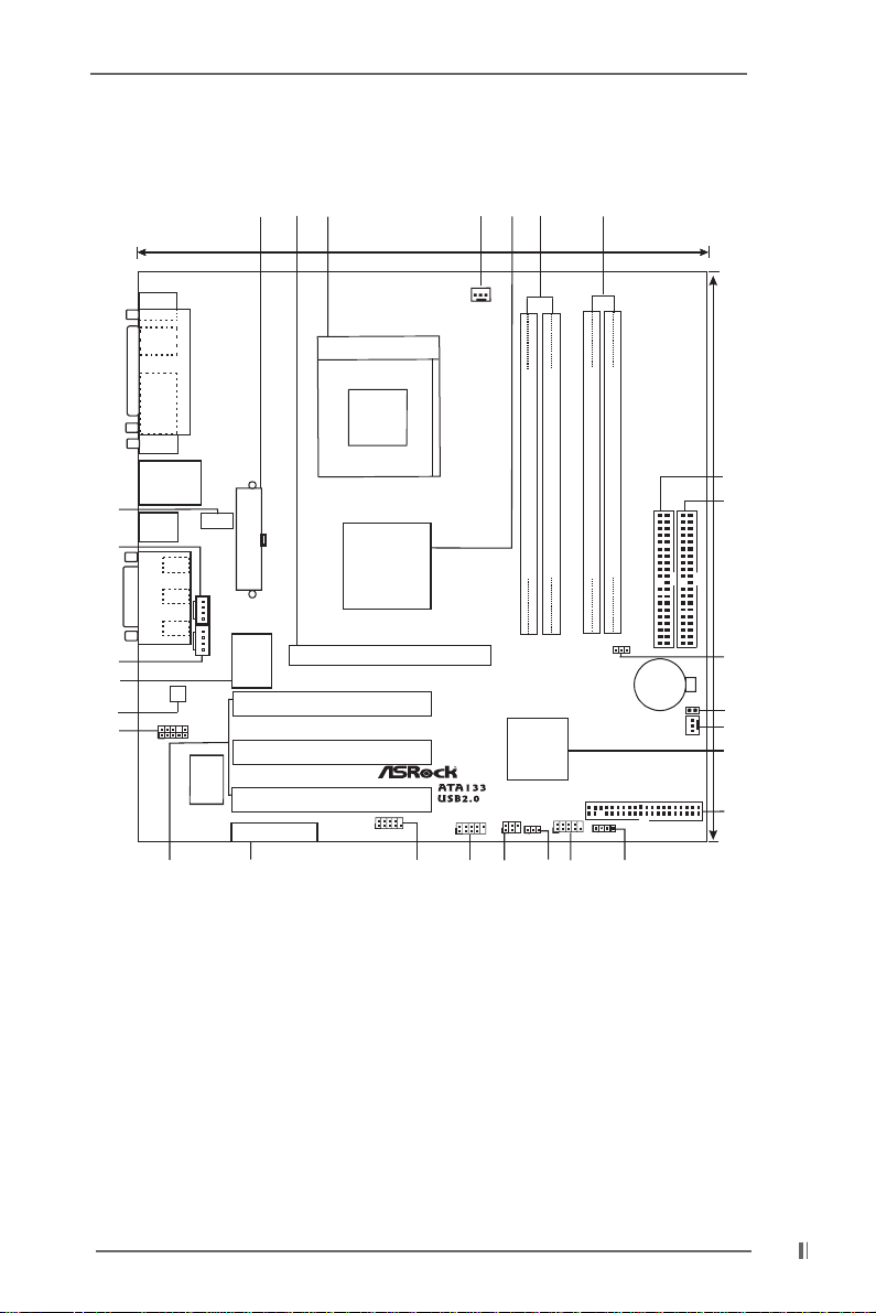
1.3 Motherboard Layout1.3 Motherboard Layout
1.3 Motherboard Layout
1.3 Motherboard Layout1.3 Motherboard Layout
27
21
24.4cm (9.6 in)
6
5
3
4
24
23
11
19
20
21
PS/2
Mouse
PS/2
Keyboard
VGA
USB01
USB23
GAME AUDIO1
GAME AUDIO1
1
LAN
Line out
Line in
Mic in
18
CPU_FAN1
SOCKET 462
PARALLEL PORT
7
IDE1
IDE2
CLRCMOS1
8
24.4cm (9.6 in)
28
17
9
16
10
LANPHY
ATX P WR1
Line
In
CD1
Mic
In
AUX1
2MB
BIOS
AUDIO
CODEC
AUDIO1
K7VM2
VIA
Chipset
Accelerated GraphicsPort
PCI 1
PCI 2
I/O
Super
26
AMR1
PCI 3
1
COM1
25
USB45
1
13
1
14
VIA
South
Bridge
IR1
1
PS2_USB_PWR1
DDR DIMM1(64/72 bit, 184-pinmodule)
10
PLED PWRBTN
1
22
DDR DIMM2(64/72 bit, 184-pinmodule)
32
PANEL1
HDLED RST
12
01
1
SPEAKER1
SDR DIMM1(64 bit, 168-pinmodule)
32
1
15
SDR DIMM2(64 bit, 168-pinmodule)
FSB_SEL1
FLOPPY1
CMOS
Battery
CHA_FAN1
1 ATX power connector (ATXPWR1) 15 Speaker connector (SPEAKER 1)
2 CPU socket 16 South Bridge controller
3 CPU fan connector (CPU_FAN1) 17 Clear CMOS jumper (CLRCMOS1)
4 North Bridge controller 18 PCI slots
5 184-pin DDR DIMM slots (blue) 19 AUDIO CODEC
6 168-pin SDRAM DIMM slots (black) 20 Front panel audio connector (AUDIO1)
7 Primary IDE connector (IDE1, blue) 21 LAN PHY
8 Secondary IDE connector (IDE2, black) 22 PS2_USB_PWR1 jumper
9 Chassis fan connector (CHA_FAN1) 23 Internal audio connector: AUX1 (white)
10 Floppy connector (FLOPPY1) 24 Internal audio connector: CD1 (black)
11 Flash Memory 25 Serial port connector (COM1)
12 System panel connector (PANEL1) 26 AMR slot
13 USB header (USB45) 27 AGP slot
14 Infrared module connector (IR1) 28 FSB_SEL1 jumper
66
6
66
Page 7
1.4 ASRock I/O1.4 ASRock I/O
1.4 ASRock I/O
1.4 ASRock I/O1.4 ASRock I/O
TMTM
TM
TMTM
11
2
1098 765
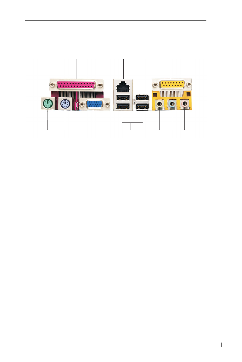
1 Parallel port 6 Line Out (Lime)
2 RJ-45 port 7 USB 2.0 ports
3 Game port 8 VGA port
4 Microphone (Pink) 9 PS/2 keyboard port (Purple)
5 Line In (Light Blue) 10 PS/2 mouse port (Green)
3
4
77
7
77
Page 8

Chapter 2 InstallationChapter 2 Installation
Chapter 2 Installation
Chapter 2 InstallationChapter 2 Installation
K7VM2 is a Micro ATX form factor (9.6" x 9.6") motherboard. Before you install the
motherboard, study the configuration of your chassis to ensure that the motherboard
fits into it.
Make sure to unplug the power cord before installing or removing the
motherboard. Failure to do so may cause physical injuries to you
and damages to motherboard components.
2.1 Screw Holes2.1 Screw Holes
2.1 Screw Holes
2.1 Screw Holes2.1 Screw Holes
Place screws into the holes indicated by circles to secure the motherboard to the
chassis.
Do not over-tighten the screws! Doing so may damage the
motherboard.
2.2 Pre-installation Precautions2.2 Pre-installation Precautions
2.2 Pre-installation Precautions
2.2 Pre-installation Precautions2.2 Pre-installation Precautions
Take note of the following precautions before you install motherboard components
or change any motherboard settings.
1. Unplug the power cord from the wall socket before touching any component.
2. To avoid damaging the motherboard components due to static electricity,
NEVER place your motherboard directly on the carpet or the like. Also
remember to use a grounded wrist strap or touch a safety grounded object
before you handle components.
3. Hold components by the edges and do not touch the ICs.
4. Whenever you uninstall any component, place it on a grounded
antistatic pad or in the bag that comes with the component.
Before you install or remove any component, ensure that the power
is switched off or the power cord is detached from the power supply.
Failure to do so may cause severe damage to the motherboard, peripherals, and/
or components.
2.3 CPU Installation2.3 CPU Installation
2.3 CPU Installation
2.3 CPU Installation2.3 CPU Installation
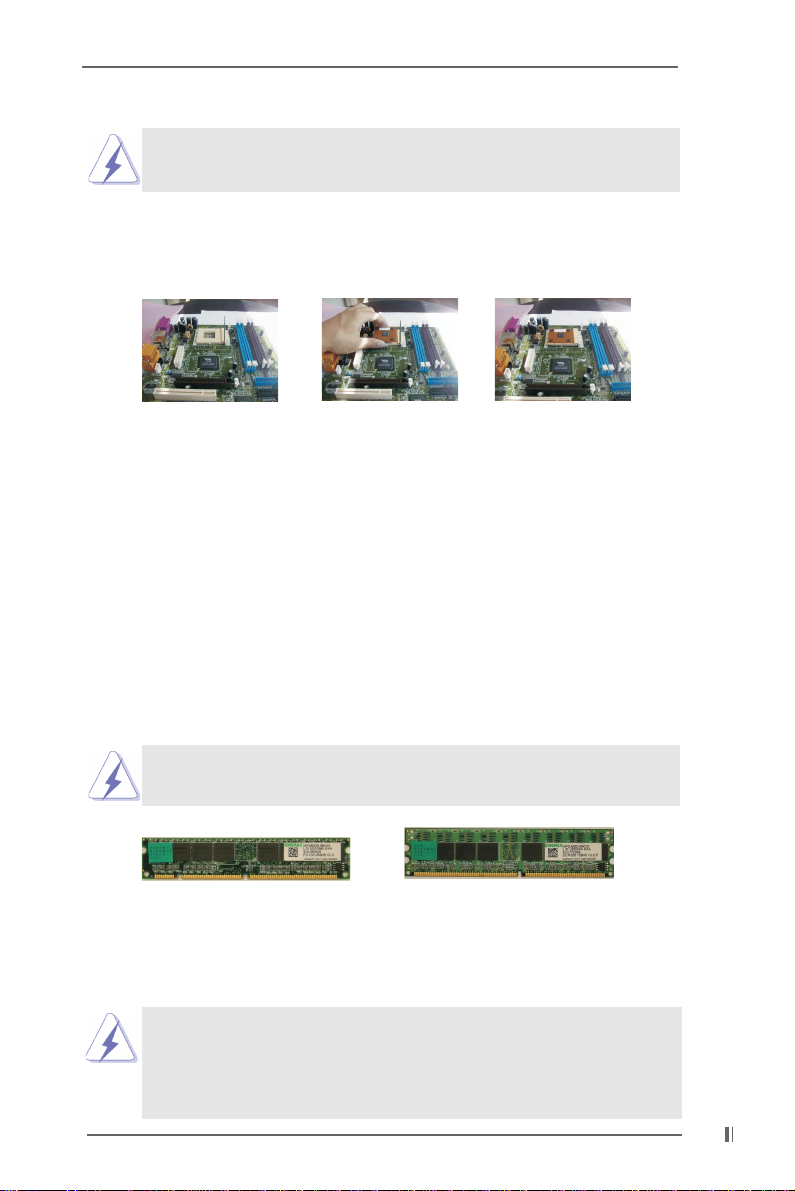
Step 1. Unlock the socket by lifting the lever up to a 90 to 100 angle.
Step 2. Position the CPU directly above the socket such that its marked corner
matches the base of the socket lever.
Step 3. Carefully insert the CPU into the socket until it fits in place.
88
8
88
Page 9
The CPU fits only in one correct orientation. DO NOT force the
CPU into the socket to avoid bending of the pins.
Step 4. When the CPU is in place, press it firmly on the socket while you push
down the socket lever to secure the CPU. The lever clicks on the side tab
to indicate that it is locked.
Step 1 Step 2, 3 Step 4
2.4 Installation of CPU Fan and Heatsink2.4 Installation of CPU Fan and Heatsink
2.4 Installation of CPU Fan and Heatsink
2.4 Installation of CPU Fan and Heatsink2.4 Installation of CPU Fan and Heatsink
AMD Ahtlon/Duron family CPUs with a speed of 600 MHz and higher require
larger heatsink and cooling fan. Thermal grease between the CPU and the
heatsink is also needed to improve heat transfer. Make sure that the CPU and
the heatsink are securely fastened and in good contact with each other. For
proper installation, please kindly refer to the instruction manuals of vendors of
CPU fan and heatsink.
2.5 Installation of Memory Modules (DIMM)2.5 Installation of Memory Modules (DIMM)
2.5 Installation of Memory Modules (DIMM)
2.5 Installation of Memory Modules (DIMM)2.5 Installation of Memory Modules (DIMM)
SDRAM (Synchronous DRAM) DIMM (Dual In-line Memory Module) has 168 pins
and DDR (Double Data Rate) SDRAM DIMM has 184 pins.
Please make sure to disconnect power supply before adding or
removing DIMMs or the system components.
168-pin RAM
The 168-pin SDRAM DIMM (black) and 184-pin DDR DIMM (blue) can be easily
distinguished by the fool-proof design.
Please do not insert both 168-pin SDRAM DIMM and 184-pin DDR
DIMM at the same time. To optimize the compatibility, it is not
recommended to use two different models of the DIMMs at the same
time.
184-pin RAM
99
9
99
Page 10
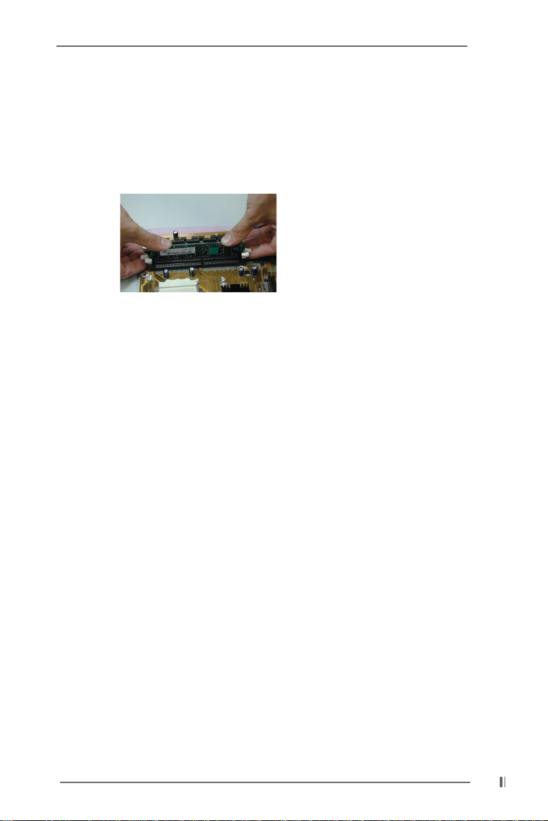
Step 1. Unlock a DIMM slot by pressing the retaining clips outward.
Step 2. Align a DIMM on the slot such that the notch on the DIMM matches the break
on the slot.
Step 3. Firmly insert the DIMM into the slot until the retaining clip snap back in place
and the DIMM is properly seated.
2.6 Expansion Slots (PCI, AMR, and AGP Slots)2.6 Expansion Slots (PCI, AMR, and AGP Slots)
2.6 Expansion Slots (PCI, AMR, and AGP Slots)
2.6 Expansion Slots (PCI, AMR, and AGP Slots)2.6 Expansion Slots (PCI, AMR, and AGP Slots)
There are 3 PCI slots, 1 AMR slot, and 1 AGP slot on K7VM2 motherboard.
PCI slots: PCI slots are used to install expansion cards that have the 32-bit PCI
interface.
AMR slot: AMR slot is used to insert ASRock AMR card with v.92 Modem
functionality. On K7VM2 motherboard, the AMR slot shares the
bracket with the slot PCI 3.
AGP slot: The AGP slot is used to install a graphics card.
The ASRock AGP slot has a special locking mechanism which
can securely fasten the graphics card inserted.
Installing an expansion cardInstalling an expansion card
Installing an expansion card
Installing an expansion cardInstalling an expansion card
Step 1. Before installing the expansion card, read the documentation of the
expansion card and make necessary hardware settings for the card.
Step 2. Remove the system unit cover (if your motherboard is already installed in a
chassis).
Step 3. Remove the bracket facing the slot that you intend to use. Keep the screw
for later use.
Step 4. Align the card connector with the slot and press firmly until the card is
completely seated on the slot.
Step 5. Fasten the card to the chassis with screws.
Step 6. Replace the system cover.
1010
10
1010
Page 11
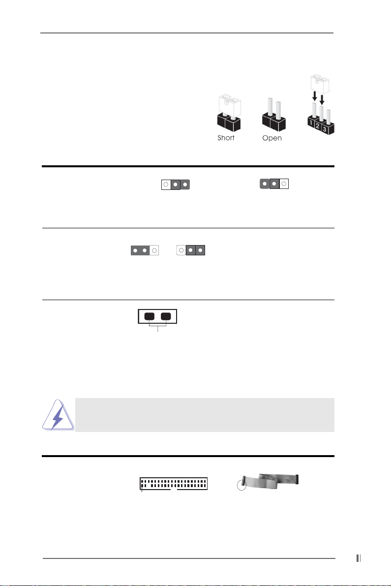
2.7 Jumpers Setup2.7 Jumpers Setup
FSB_SEL1
1_2
2.7 Jumpers Setup
2.7 Jumpers Setup2.7 Jumpers Setup
The illustration shows how jumpers are setup.
When the jumper cap is placed on pins, the jumper
is “SHORT”. If no jumper cap is placed on pins,
the jumper is “OPEN”. The illustration shows a
3-pin jumper whose pin1 and pin2 are “SHORT”
when jumper cap is placed on these 2 pins.
Jumper Setting Description
FSB_SEL1
(see p.6 item 28)
FSB_SEL1
2_3
FSB 100 MHz FSB 133 MHz
Note: Follow the figures to set the CPU front side bus frequency.
PS2_USB_PWR1 Short pin2, pin3 to enable
1_2
2_3
(see p.6 item 22) +5VSB (standby) for PS/2 or
+5V +5VSB USB wake up events.
Note: To select +5VSB, it requires 2 Amp and higher standby current.
CLRCMOS1 Disconnect the power cord,
(see p.6 item 17) then short the solder points
solder points to clear CMOS by using
metal material, e.g., a paper
clip.
2.8 Connectors2.8 Connectors
2.8 Connectors
2.8 Connectors2.8 Connectors
Connectors are NOT jumpers. DO NOT place jumper caps over
these connectors.
Connecto r Figure Description
FDD connector
(33-pin FLOPPY1)
(see p.6 item 10)
Pin1
FLOPPY1
Red marking
Note: Match the red marking on the floppy ribbon cable with Pin1.
1111
11
1111
Page 12
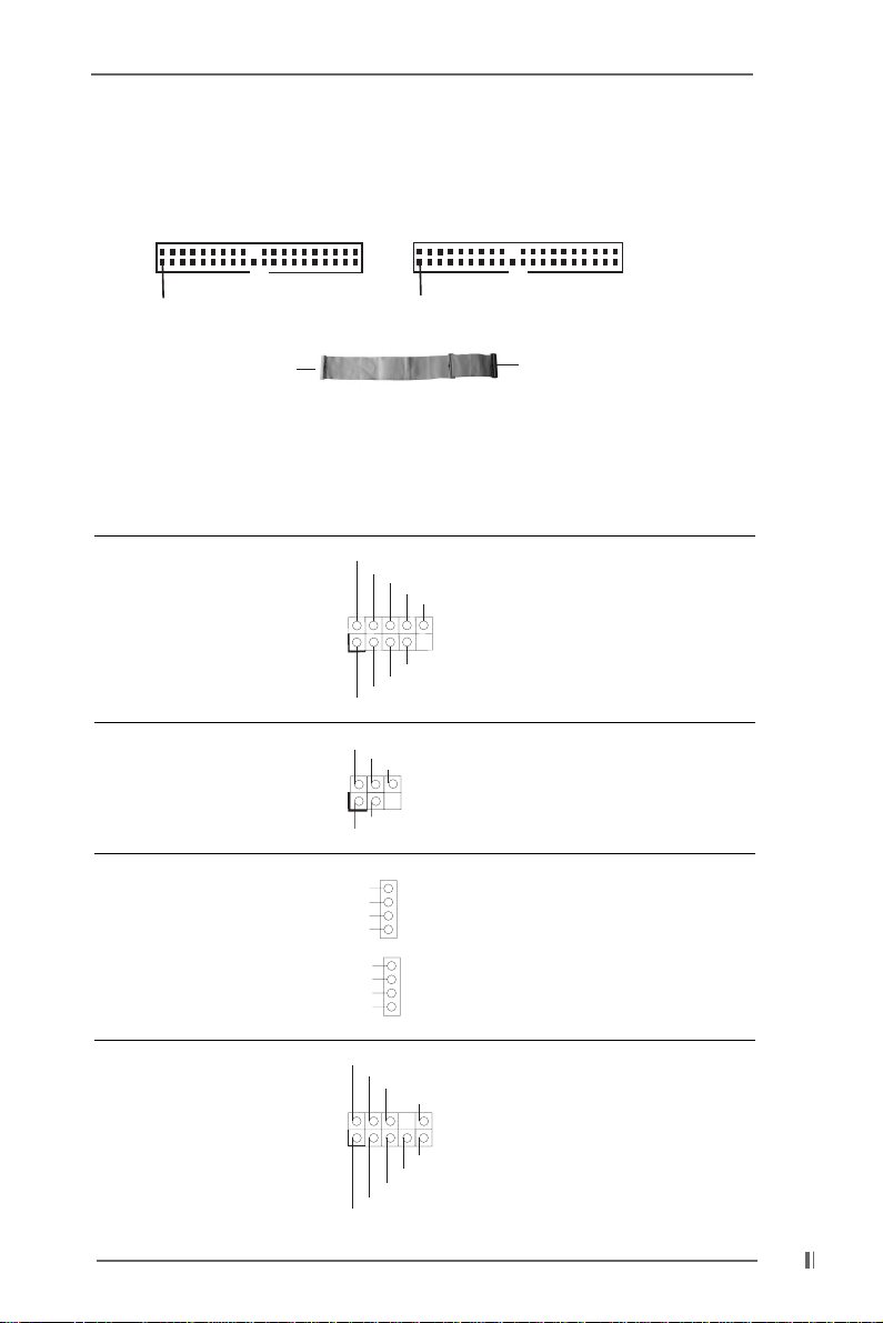
Primary IDE connector (Blue) Secondary IDE connector (Black)
(39-pin IDE1) (39-pin IDE2)
(see p.6 item 7) (see p.6 item 8)
PIN1
Connect to the motherboard
IDE1
PIN1
Blue
IDE2
Black
Connect to the IDE devices
80-Pin ATA 100/133 cable
Note: To optimize compatibility and performance, please connect your hard disk
drive to the primary IDE connector (IDE1, blue) and CD-ROM to the
secondary IDE connector (IDE2, black).
USB header ASRock I/OTM already
(9-pin USB45) provided 4 default USB ports.
(see p.6 item 13) If the 4 USB ports on the rear
Infrared module connector This connector supports an
(5-pin IR1) optional wireless transmitting
(see p.6 item 14) and receiving infrared module.
Internal audio connectors These connectors allow you
(4-pin CD1, 4-pin AUX1) CD1 to receive stereo audio input
(CD1: see p.6 item 24) from sound sources such as
(AUX1: see p.6 item 23) a CD-ROM, DVD-ROM, TV
USB_PWR
P-5
P+5
GND
DUMMY
1
1
CD-L
CD-R
AUX-L
AUX1 tuner card, or MPEG card.
AUX-R
GND
GND
GND
GND
IRTX
P-4
USB_PWR
+5V
GND
IRRX
GND
P+4
DUMMY
panel are not sufficient, an
USB header is available for 2
additional USB ports.
1
GND
+5VA
MIC-POWER
MIC
BACKOUT-R
BACKOUT-L
AUD-OUT-L
DUMMY
AUD-OUT-R
control of audio devices.
Audio1 connector This is an interface for front
(9-pin AUDIO1) panel audio cable that allows
(see p.6 item 20) convenient connection and
1212
12
1212
Page 13
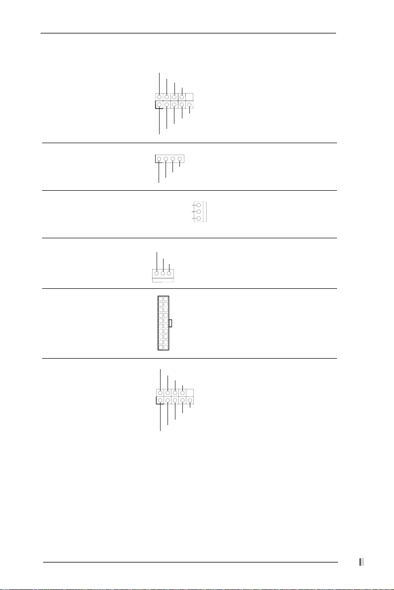
System panel connector This connector accommo(9-pin PANEL1) dates several system front
PLED+
PLED-
PWRBTN#
GND
(see p.6 item 12) panel functions.
1
HDLED+
GND
HDLED-
DUMMY
RESET#
Speaker1 connector This connector allows you to
(4-pin SPEAKER 1) attach to an external speaker.
(see p.6 item 15)
Chassis fan connector Connect the fan cable to the
(3-pin CHA_FAN1) connector matching the black
1
SPEAKER
DUMMY
DUMMY
+5V
CHA_FAN_SPEED
+12V
GND
(see p.6 item 9) wire to the ground pin.
CPU fan connector Connect the fan cable to the
(3-pin CPU_FAN1) connector matching the black
GND
+12V
CPU_FAN_SPEED
(see p.6 item 3) wire to the ground pin.
ATX power connector Connect an ATX power
(20-pin ATXPWR1) supply to the connector.
(see p.6 item 1)
1
RRXD1
DDTR#1
TTXD1
DDCD#1
DDSR#1
CCTS#1
RRTS#1
GND
RRI#1
COM1 connector This connector supports a
(9-pin COM1) serial port module.
(see p.6 item 25)
1313
13
1313
Page 14

Chapter 3 BIOS SetupChapter 3 BIOS Setup
Chapter 3 BIOS Setup
Chapter 3 BIOS SetupChapter 3 BIOS Setup
3.1 BIOS Setup Utility3.1 BIOS Setup Utility
3.1 BIOS Setup Utility
3.1 BIOS Setup Utility3.1 BIOS Setup Utility
This section explains how to configure your system using the BIOS Setup utility. The
Flash Memory on the motherboard stores the BIOS Setup utility. When you start up
the computer, there is a chance for you to run the BIOS Setup. Press <F2> during the
Power-On-Self-Test (POST) to enter the BIOS Setup utility, otherwise, POST
continues with its test routines.
If you wish to enter the BIOS Setup after POST, restart the system by pressing
<Ctl> + <Alt> + <Delete>, or by pressing the reset button on the system chassis. You
can also restart by turning the system off and then back on.
The BIOS Setup utility is designed to be user-friendly. It is a menu-driven program,
which allows you to scroll through its various sub-menus and select among the
predetermined choices.
Because the BIOS software is constantly being updated, the
following BIOS setup screens and descriptions are for reference
purpose only, and may not exactly match what you see on your
screen.
3.1.1 BIOS Menu Bar3.1.1 BIOS Menu Bar
3.1.1 BIOS Menu Bar
3.1.1 BIOS Menu Bar3.1.1 BIOS Menu Bar
The top of the screen has a menu bar with the following selections:
MAIN Sets up the basic system configuration
ADVANCED Sets up the advanced features
SECURITY Sets up the security features
POWER Configures Power Management features
BOOT Configures the default system device that is used
to locate and load the Operating System
EXIT Exits the current menu or the BIOS Setup
To access the menu bar items, press the right or left arrow key on the keyboard
until the desired item is highlighted.
3.1.2 Legend Bar3.1.2 Legend Bar
3.1.2 Legend Bar
3.1.2 Legend Bar3.1.2 Legend Bar
At the bottom of the Setup Screen is a legend bar. The following table lists the
keys in the legend bar with their corresponding functions.
1414
14
1414
Page 15
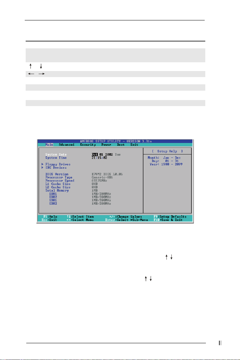
Navigation Key(s) Function Description
<F1> Displays the General Help Screen
<ESC> Jumps to the Exit menu or returns to the upper menu
from the current menu
/ Moves cursor up or down between fields
/ Selects menu to the left or right
+ / - Increases or decreases values
<Enter> Brings up a selected menu for a highlighted field
<F9> Resets the current screen to its Setup Defaults
<F10> Saves changes and exits Setup
3.2 Main Menu3.2 Main Menu
3.2 Main Menu
3.2 Main Menu3.2 Main Menu
When you enter the BIOS Setup utility, the following screen appears.
System Date [Month/Day/Year]
Set the system date that you specify. Valid values for month, day, and year are
Month: (Jan to Dec), Day: (1 to 31), Y ear: (up to 2099). Use keys to move
between the Month, Day and Year fields.
System Time [Hour:Minute:Second]
Set the system to the time that you specify. Use keys to move between
the Hour, Minute and Second fields.
Floppy Drives
Use this to set the type of floppy drives installed.
IDE Devices
Use this to configure IDE devices.
1515
15
1515
Page 16
TYPE
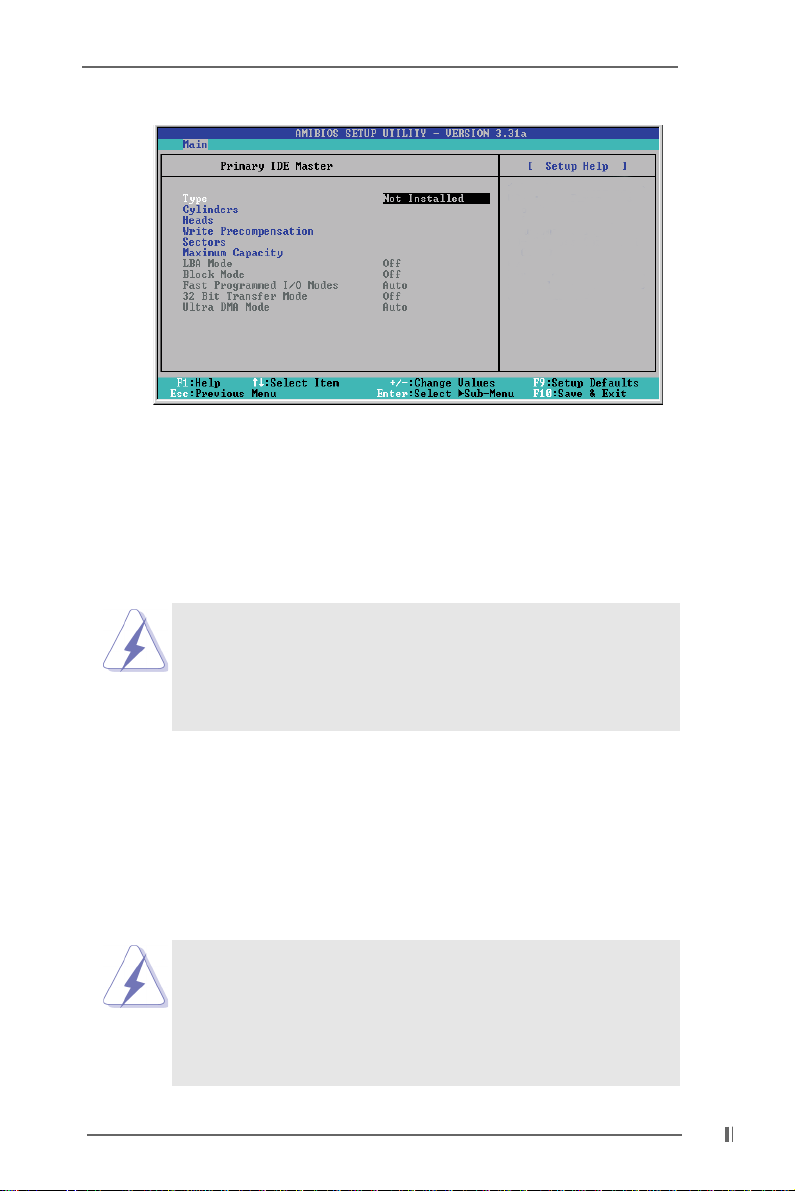
It allows user to select the type of the IDE Drive. Below are the
configuration options. After making your selections on this sub-menu,
press <ESC> key to return to the upper menu, in which the hard disk drive
field will display the size for the hard disk drive that you configured.
[USER]: It allows user to manually enter the number of cylinders, heads,
and sectors per track for the drive.
Before attempting to configure a hard disk drive, make sure you
have the correct configuration information supplied by the drive
manufacturer. Incorrect settings may cause the system to fail to
recognize the installed hard disk.
[Auto]: Select [Auto] to automatically detect hard disk drive. If
auto-detection is successful, the BIOS Setup automatically fills in the
correct values for the remaining fields on this sub-menu. If the autodetection fails, it may due to that the hard disk is too old or too new.
If the hard disk was already formatted on an older system, the BIOS
Setup may detect incorrect parameters. In these cases, select [User]
to manually enter the IDE hard disk drive parameters.
After entering the hard disk information into BIOS, use a disk
utility, such as FDISK, to partition and format new IDE hard disk
drives. This is necessary so that you can write or read data
from the hard disk. Make sure to set the partition of the Primary
IDE hard disk drives to active.
1616
16
1616
Page 17

[CD/DVD]: This is used for IDE CD/DVD drives.
[ARMD]: This is used for IDE ARMD (Accelerated Removable Media
Device), such as MO.
Cylinders
This is used to configure the number of cylinders. Refer to the drive
documentation to determine the correct value.
Heads
This is used to configure the number of read/write heads. Refer to the
drive documentation to determine the correct values.
Write Pre-compensation
Enter Write Pre-compensation sector. Refer to the drive documentation to
determine the correct value.
Sectors
This is used to configure the number of sectors per track. Refer to the
drive documentation to determine the correct value.
Maximum Capacity
This field shows the drive’s maximum capacity as calculated by the BIOS
based on the drive information you entered.
LBA Mode
This allows user to select the LBA mode for a hard disk > 512 MB under
DOS and Windows; for Netware and UNIX user, select [Off] to disable the
LBA mode.
Block Mode
Set the block mode to [On] will enhance hard disk performance by reading
or writing more data during each transfer.
Fast Programmed I/O Modes
This allows user to set the PIO mode to enhance hard disk performance by
optimizing the hard disk timing.
32 Bit Transfer Mode
It allows user to enable 32-bit access to maximize the IDE hard disk data
transfer rate.
Ultra DMA Mode
Ultra DMA capability improves transfer speeds and data integrity for
compatible IDE devices. Set to [Disabled] to suppress Ultra DMA capability.
3.3 Advanced, Security, Power, Boot, and Exit Menus3.3 Advanced, Security, Power, Boot, and Exit Menus
3.3 Advanced, Security, Power, Boot, and Exit Menus
3.3 Advanced, Security, Power, Boot, and Exit Menus3.3 Advanced, Security, Power, Boot, and Exit Menus
Detailed descriptions of these menus are listed in the Appendix, see p.19.
1717
17
1717
Page 18

Chapter 4 Software SupporChapter 4 Software Suppor
Chapter 4 Software Suppor
Chapter 4 Software SupporChapter 4 Software Suppor
4.1 Install Operating System4.1 Install Operating System
4.1 Install Operating System
4.1 Install Operating System4.1 Install Operating System
This motherboard supports various Windows operating systems (98SE / ME / 2000
/ XP). Because motherboard settings and hardware options vary, use the setup
procedures in this chapter for general reference only. Refer to your OS documentation for more information.
4.2 Support CD Information4.2 Support CD Information
4.2 Support CD Information
4.2 Support CD Information4.2 Support CD Information
The Support CD that came with the motherboard contains necessary drivers and
useful utilities that enhance the motherboard features.
4.2.1 Running The Support CD4.2.1 Running The Support CD
4.2.1 Running The Support CD
4.2.1 Running The Support CD4.2.1 Running The Support CD
To begin using the support CD, insert the CD into your CD-ROM drive. The CD
automatically displays the Main Menu if “AUTORUN” is enabled in your computer.
If the Main Menu did not appear automatically, locate and double click on the
file ASSETUP.EXE from the BIN folder in the Support CD to display the menus.
4.2.2 Drivers Menu4.2.2 Drivers Menu
4.2.2 Drivers Menu
4.2.2 Drivers Menu4.2.2 Drivers Menu
The Drivers Menu shows the available devices drivers if the system detects
installed devices. Install the necessary drivers to activate the devices.
4.2.3 Utilities Menu4.2.3 Utilities Menu
4.2.3 Utilities Menu
4.2.3 Utilities Menu4.2.3 Utilities Menu
The Utilities Menu shows the applications software that the motherboard
supports. Click on a specific item then follow the installation wizard to install it.
tt
t
tt
4.2.4 ASRock PC-DIY Live Demo Program4.2.4 ASRock PC-DIY Live Demo Program
4.2.4 ASRock PC-DIY Live Demo Program
4.2.4 ASRock PC-DIY Live Demo Program4.2.4 ASRock PC-DIY Live Demo Program
ASRock presents you a multimedia PC-DIY live demo, which shows you how
to install your own PC system step by step. You can find the file through the
following path:
..\ MPEGAV \ AVSEQ01.DAT
To see this demo program, you can run Microsoft Media Player to play the file.
4.2.5 Contact Information4.2.5 Contact Information
4.2.5 Contact Information
4.2.5 Contact Information4.2.5 Contact Information
If you need to contact ASRock or want to know more about ASRock, welcome
to ASRock’s website: http://www.asrock.com; or you may contact your dealer
for further information.
1818
18
1818
Page 19
Appendix: Advanced BIOS SetupAppendix: Advanced BIOS Setup
Appendix: Advanced BIOS Setup
Appendix: Advanced BIOS SetupAppendix: Advanced BIOS Setup
This section will introduce you the following BIOS Setup menus: “Advanced,”
“Security,” “Power,” “Boot,” and “Exit.”
1. Advanced BIOS Setup Menu1. Advanced BIOS Setup Menu
1. Advanced BIOS Setup Menu
1. Advanced BIOS Setup Menu1. Advanced BIOS Setup Menu
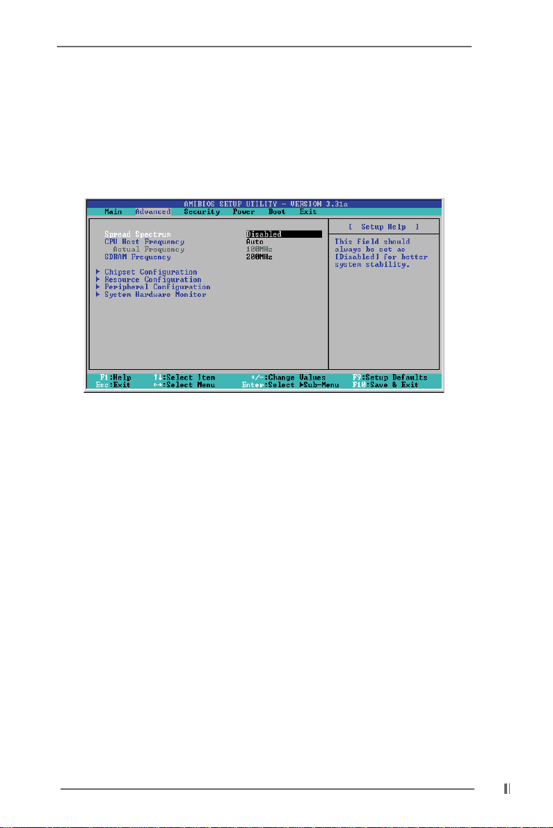
Spread Spectrum:
This field should always be “Disabled” for better system stability.
CPU Host Frequency:
[Auto]: The motherboard detects the jumper setup and sets the CPU host
frequency automatically.
[Manual]: This allows user to set CPU host frequency manually. However,
this is not recommended unless user thoroughly knows the feature.
Wrong setup may cause problems during operation.
SDRAM Frequency:
[Auto]: The motherboard detects the memory module(s) inserted and
automatically assigns appropriate frequency.
[Other values]: This allows user to select the value as operating frequency.
Chipset Configuration:
AGP Mode: This motherboard supports the AGP 4X interface that transfers
video data at 1066MB/s. Other configuration options are 2X mode and 1X
mode.
AGP Aperture Size: It refers to a section of the PCI memory address range
used for graphics memory. We recommend that you leave this field at the
default value unless your AGP card requires other sizes.
OnBoard VGA Share Memory: This allows you to select the size of share
memory for onboard VGA. Onboard VGA will get better resolution if larger
1919
19
1919
Page 20
size of share memory is selected. Please do not select [None] if AGP or PCI
graphics card is not inserted.
PCI Delay Transaction: Enable PCI Delay Transaction feature will free the PCI
Bus when the CPU is accessing 8-bit ISA cards. Disable this feature when
using ISA cards that are not PCI 2.1 compliant.
USB Controller: Use this to enable or disable the use of USB controller.
USB Device Legacy Support: Use this to enable or disable support to emulate
legacy I/O devices such as mouse, keyboard,... etc.
Resource Configuration:
PCI Latency Timer (PCI Clocks): The default is 32. We recommend you to
keep the default value unless your PCI expansion cards’ specifications
require other settings.
Primary Graphics Adapter: Select PCI, OnBoard VGA, or AGP as the primary
graphics adapter.
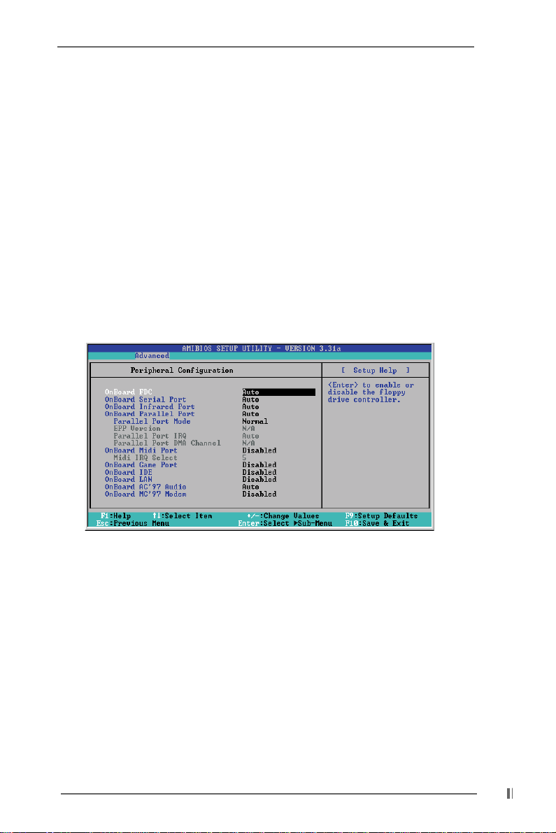
Peripheral Configuration:
OnBoard FDC: Use this to enable or disable floppy drive controller.
OnBoard Serial Port: Use this to set addresses for the onboard serial ports or
disable serial ports. Configuration options: [Auto], [Disabled], [3F8 / IRQ4 /
COM1], [2F8 / IRQ3 / COM2], [3E8 / IRQ4 / COM3], [2E8 / IRQ3 / COM4].
OnBoard Infrared Port: This allows you to enable or disable the onboard
infrared port feature. Select [Auto] will enable this feature if the infrared
module is installed.
OnBoard Parallel Port: Select Parallel Port address or disable Parallel Port.
Configuration options: [Auto], [Disabled], [378], [278].
Parallel Port Mode: Set the operation mode of the parallel port.
OnBoard Midi Port: Select address for Midi Port or disable Midi Port. Configu
ration options: [Disabled], [330], [300], [290], [292].
Midi IRQ Select: Use this to select Midi IRQ. Configuration options: [5],
[10], [11]. The default is 5.
2020
20
2020
Page 21
OnBoard Game Port: Select address for Game Port or disable Game Port.
Configuration options: [200h], [208h], [Disabled].
OnBoard IDE: To enable either the primary IDE channel or the secondary IDE
channel, set to [Disabled] will disable the both.
Configuration options: [both], [Disabled], [Primary], [Secondary].
OnBoard AC’97 Audio: Enable or disable onboard AC’97 audio feature.
OnBoard MC’97 Modem: Enable or disable onboard MC’97 modem feature.
2. Security Setup Menu2. Security Setup Menu
2. Security Setup Menu
2. Security Setup Menu2. Security Setup Menu
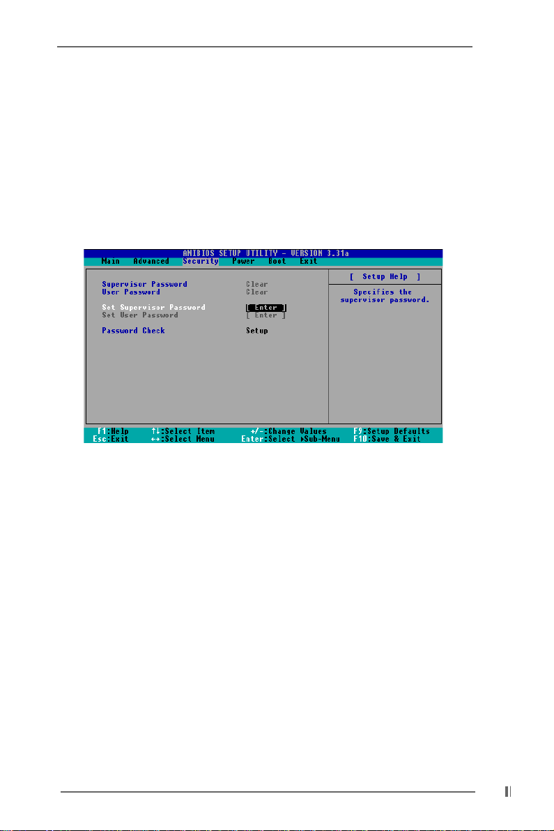
Supervisor Password: This field shows the status of the Supervisor Password.
[Clear]: No password has been set.
[Set]: Supervisor password has been set.
User Password: This field shows the status of the User Password.
[Clear]: No password has been set.
[Set]: User password has been set.
Set Supervisor Password: Press <Enter> to set Supervisor Password. Valid
password can be a 1 to 6 alphanumeric characters combination. If you already
have a password, you must enter your current password first in order to
create a new password.
Set User Password: Press <Enter> to set User Password. Valid password can
be a 1 to 6 alphanumeric characters combination. If you already have a
password, you must enter your current password first in order to create a new
password.
Password Check: Select the check point for “Password Check”. Configuration
options: [Setup], [Always]. If [Setup] option is selected, the “Password Check”
is performed before BIOS setup. If [Always] option is selected, the “Password
Check” is performed before both boot-up and BIOS setup.
2121
21
2121
Page 22
3. Power Setup Menu3. Power Setup Menu
3. Power Setup Menu
3. Power Setup Menu3. Power Setup Menu
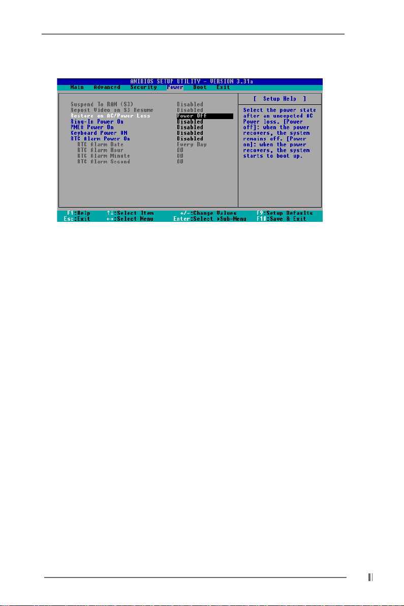
Suspend to RAM (S3): This field allows you to select whether to auto-detect or
disable the ACPI Suspend-to-RAM feature. Select [Auto] will enable this feature
if the system supports it.
Repost Video on S3 Resume: This feature allows you to repost video on S3
resume.
Restore on AC/Power Loss: This allows you to set the power state after an
unexpected AC power loss. If [Power Off] is selected, the AC power remains
off when the power recovers. If [Power On] is selected, the AC power
resumes and the system starts to boot up when the power recovers.
Ring-In Power On: Use this to enable or disable Ring-in signals to turn on the
system from the power-soft-off mode.
PME# Power On: Use this to enable or disable PCI PME# to turn on the system from
the power-soft-off mode.
Keyboard Power On: Use this to enable or disable keyboard to turn on the system
from the power-soft-off mode.
RTC Alarm Power On: Use this to enable or disable RTC(Real Time Clock) to power
on the system. If [Enable] is selected, you must fill the RTC Alarm Date / Hour /
Minute / Second sub-fields with the actual wake up time you desire.
2222
22
2222
Page 23
4. Boot Setup Menu4. Boot Setup Menu
4. Boot Setup Menu
4. Boot Setup Menu4. Boot Setup Menu
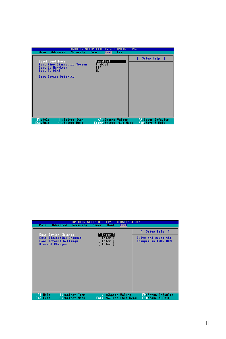
Quick Boot Mode: This mode speeds up the boot-up routine by skipping memory
retestings.
Boot-time Diagnostic Screen: This screen shows CPU and hardware
information during Power-On-Self-Test (POST) routine. If this screen is disabled,
only ASRock logo is shown during the boot up process.
Boot Up Num-Lock: This automatically activates the Numeric Lock function after
boot up.
Boot to OS/2: This enables boot up to OS/2 operating system.
Boot Device Priority: This allows you to set the boot device priority.
5. Exit Menu5. Exit Menu
5. Exit Menu
5. Exit Menu5. Exit Menu
2323
23
2323
Page 24

Exit Saving Changes: After you enter the sub-menu, the message “Save current
settings and exit” will appear. If you press <ENTER>, it will save the current
settings and exit the BIOS SETUP Utility.
Exit Discarding Changes: After you enter the submenu, the message “Quit
without saving changes” will appear. If you press <ENTER>, you will exit the
BIOS Setup Utility without making any changes to the settings.
Load Default Settings: This loads the default values for all the setup configuration.
Discard Changes: After you enter the sub-menu, the message “Load setup
original values” will appear. If you press <ENTER>, original values will be restored.
All changes are discarded.
2424
24
2424
 Loading...