

Page 1

Version 1.0
Published January 2022
Copyright©2022 ASRock INC. All rights reserved.
Copyright Notice:
No part of this documentation may be reproduced, transcribed, transmitted, or
translated in any language, in any form or by any means, except duplication of
documentation by the purchaser for backup purpose, without written consent of
ASRock Inc.
Products and corporate names appearing in this documentation may or may not
be registered trademarks or copyrights of their respective companies, and are used
only for identication or explanation and to the owners’ benet, without intent to
infringe.
Disclaimer:
Specications and information contained in this documentation are furnished for
informational use only and subject to change without notice, and should not be
constructed as a commitment by ASRock. ASRock assumes no responsibility for
any errors or omissions that may appear in this documentation.
With respect to the contents of this documentation, ASRock does not provide
warranty of any kind, either expressed or implied, including but not limited to
the implied warranties or conditions of merchantability or tness for a particular
purpose.
In no event shall ASRock, its directors, ocers, employees, or agents be liable for
any indirect, special, incidental, or consequential damages (including damages for
loss of prots, loss of business, loss of data, interruption of business and the like),
even if ASRock has been advised of the possibility of such damages arising from any
defect or error in the documentation or product.
is device complies with Part 15 of the FCC Rules. Operation is subject to the following
two conditions:
(1) this device may not cause harmful interference, and
(2) this device must accept any interference received, including interference that
may cause undesired operation.
CALIFORNIA, USA ONLY
e Lithium battery adopted on this motherboard contains Perchlorate, a toxic substance
controlled in Perchlorate Best Management Practices (BMP) regulations passed by the
California Legislature. When you discard the Lithium battery in California, USA, please
follow the related regulations in advance.
“Perchlorate Material-special handling may apply, see www.dtsc.ca.gov/hazardouswaste/
perchlorate”
ASRock Website: http://www.asrock.com
Page 2

AUSTRALIA ONLY
Our goods come with guarantees that cannot be excluded under the Australian Consumer
Law. You are entitled to a replacement or refund for a major failure and compensation for
any other reasonably foreseeable loss or damage caused by our goods. You are also entitled
to have the goods repaired or replaced if the goods fail to be of acceptable quality and the
failure does not amount to a major failure. If you require assistance please call ASRock Tel
: +886-2-28965588 ext.123 (Standard International call charges apply)
e terms HDMI® and HDMI High-Denition Multimedia Interface, and the HDMI
logo are trademarks or registered trademarks of HDMI Licensing LLC in the United
States and other countries.
INTEL END USER SOFTWARE LICENSE AGREEMENT
IMPORTANT - READ BEFORE COPYING, INSTALLING OR USING.
LICENSE. Licensee has a license under Intel’s copyrights to reproduce Intel’s Soware
only in its unmodied and binary form, (with the accompanying documentation, the
“Soware”) for Licensee’s personal use only, and not commercial use, in connection with
Intel-based products for which the Soware has been provided, subject to the following
conditions:
(a) Licensee may not disclose, distribute or transfer any part of the Soware, and You agree
to prevent unauthorized copying of the Soware.
(b) Licensee may not reverse engineer, decompile, or disassemble the Soware.
(c) Licensee may not sublicense the Soware.
(d) e Soware may contain the soware and other intellectual property of third party
suppliers, some of which may be identied in, and licensed in accordance with, an enclosed
license.txt le or other text or le.
(e) Intel has no obligation to provide any support, technical assistance or updates for the
Soware.
OWNERSHIP OF SOFTWARE AND COPYRIGHTS. Title to all copies of the Soware
remains with Intel or its licensors or suppliers. e Soware is copyrighted and protected
by the laws of the United States and other countries, and international treaty provisions.
Licensee may not remove any copyright notices from the Soware. Except as otherwise
expressly provided above, Intel grants no express or implied right under Intel patents,
copyrights, trademarks, or other intellectual property rights. Transfer of the license terminates Licensee’s right to use the Soware.
DISCLAIMER OF WARRANTY. e Soware is provided “AS IS” without warranty of
any kind, EITHER EXPRESS OR IMPLIED, INCLUDING WITHOUT LIMITATION,
WARRANTIES OF MERCHANTABILITY OR FITNESS FOR ANY PARTICULAR PURPOSE.
LIMITATION OF LIABILITY. NEITHER INTEL NOR ITS LICENSORS OR SUPPLIERS
WILL BE LIABLE FOR ANY LOSS OF PROFITS, LOSS OF USE, INTERRUPTION OF
BUSINESS, OR INDIRECT, SPECIAL, INCIDENTAL, OR CONSEQUENTIAL DAMAG
Page 3

ES OF ANY KIND WHETHER UNDER THIS AGREEMENT OR OTHERWISE, EVEN
IF INTEL HAS BEEN ADVISED OF THE POSSIBILITY OF SUCH DAMAGES.
LICENSE TO USE COMMENTS AND SUGGESTIONS. is Agreement does NOT
obligate Licensee to provide Intel with comments or suggestions regarding the Soware.
However, if Licensee provides Intel with comments or suggestions for the modication,
correction, improvement or enhancement of (a) the Soware or (b) Intel products or
processes that work with the Soware, Licensee grants to Intel a non-exclusive, worldwide,
perpetual, irrevocable, transferable, royalty-free license, with the right to sublicense, under
Licensee’s intellectual property rights, to incorporate or otherwise utilize those comments
and suggestions.
TERMINATION OF THIS LICENSE. Intel or the sublicensor may terminate this license
at any time if Licensee is in breach of any of its terms or conditions. Upon termination,
Licensee will immediately destroy or return to Intel all copies of the Soware.
THIRD PARTY BENEFICIARY. Intel is an intended beneciary of the End User License
Agreement and has the right to enforce all of its terms.
U.S. GOVERNMENT RESTRICTED RIGHTS. e Soware is a commercial item (as
dened in 48 C.F.R. 2.101) consisting of commercial computer soware and commercial
computer soware documentation (as those terms are used in 48 C.F.R. 12.212), consistent
with 48 C.F.R. 12.212 and 48 C.F.R 227.7202-1 through 227.7202-4. You will not provide
the Soware to the U.S. Government. Contractor or Manufacturer is Intel Corporation,
2200 Mission College Blvd., Santa Clara, CA 95054.
EXPORT LAWS. Licensee agrees that neither Licensee nor Licensee’s subsidiaries will
export/re-export the Soware, directly or indirectly, to any country for which the U.S.
Department of Commerce or any other agency or department of the U.S. Government
or the foreign government from where it is shipping requires an export license, or other
governmental approval, without rst obtaining any such required license or approval. In
the event the Soware is exported from the U.S.A. or re-exported from a foreign destination by Licensee, Licensee will ensure that the distribution and export/re-export or import
of the Soware complies with all laws, regulations, orders, or other restrictions of the U.S.
Export Administration Regulations and the appropriate foreign government.
APPLICABLE LAWS. is Agreement and any dispute arising out of or relating to it will
be governed by the laws of the U.S.A. and Delaware, without regard to conict of laws
principles. e Parties to this Agreement exclude the application of the United Nations
Convention on Contracts for the International Sale of Goods (1980). e state and federal
courts sitting in Delaware, U.S.A. will have exclusive jurisdiction over any dispute arising
out of or relating to this Agreement. e Parties consent to personal jurisdiction and venue
in those courts. A Party that obtains a judgment against the other Party in the courts identied in this section may enforce that judgment in any court that has jurisdiction over the
Parties.
Licensee’s specic rights may vary from country to country.
Page 4

CE Warning
is device complies with directive 2014/53/EU issued by the Commision of the European
Community.
is equipment complies with EU radiation exposure limits set forth for an uncontrolled
environment.
is equipment should be installed and operated with minimum distance 20cm between
the radiator & your body.
Operations in the 5.15-5.35GHz band are restricted to indoor usage only.
Radio transmit power per transceiver type
Function Frequency Maximum Output Power (EIRP)
2400-2483.5 MHz 18.5 + / -1.5 dbm
5150-5250 MHz 21.5 + / -1.5 dbm
WiFi
Bluetooth 2400-2483.5 MHz 8.5 + / -1.5 dbm
5250-5350 MHz
5470-5725 MHz
18.5 + / -1.5 dbm (no TPC)
21.5 + / -1.5 dbm (TPC)
25.5 + / -1.5 dbm (no TPC)
28.5 + / -1.5 dbm (TPC)
Page 5

Motherboard Layout
PCIE1
DDR 4_A1 (6 4 bit, 28 8-pin m odule )
DDR 4_B1 (6 4 bit, 28 8-pin m odule )
CPU_FAN1
CHA_FAN1/WP
RoHS
H610M-ITX/ac
Intel
H610
ATXPWR1
USB3_ 3_4
1
Top:
LINE I N
Cent er:
FRON T
Bott om:
MIC IN
SATA3_3
SATA3_2
1
CLRMOS1
SATA3_1
SATA3_0
M2_WIFI1
CHA_FAN2
ADDR_LED1
1
M2_1
Top:
RJ-45
USB 2.0
T: USB1
B: USB2
PS2
Keyb oard
/Mou se
USB 3.2 Gen1
T: USB3_1
B: USB3_2
HDM I1
DP1
1
HD_AUDIO1
PANEL1
HDLED RESE T
PLED PWRBT N
1
1
USB_3_4
1
SPEAKER1
7
4
9
14
8
16
15
6
5
3
2
10
11
12
13
17
1
H610M-ITX/ac
English
1
Page 6

No. Description
1 Chassis Fan Connector (CHA_FAN2)
2 ATX 12V Power Connector (ATX12V1)
3 CPU Fan Connector (CPU_FAN1)
4 Chassis/Waterpump Fan Connector (CHA_FAN1/WP)
5 Addressable LED Header (ADDR_LED1)
6 2 x 288-pin DDR4 DIMM Slots (DDR4_A1, DDR4_B1)
7 ATX Power Connector (ATXPWR1)
8 USB 3.2 Gen1 Header (USB3_3_4)
9 SATA3 Connector (SATA3_1)
10 SATA3 Connector (SATA3_0)
11 SATA3 Connector (SATA3_3)
12 SATA3 Connector (SATA3_2)
13 System Panel Header (PANEL1)
14 USB 2.0 Header (USB_3_4)
15 Clear CMOS Jumper (CLRMOS1)
16 Chassis Speaker Header (SPEAKER1)
17 Front Panel Audio Header (HD_AUDIO1)
English
2
Page 7

H610M-ITX/ac
I/O Panel
3
1
10
No. Description No. Description
1 PS/2 Mouse/Keyboard Port 6 Antenna Ports
2 LAN RJ-45 Port* 7 USB 2.0 Ports (USB12)
3 Line In (Light Blue)** 8 USB 3.2 Gen1 Ports (USB3_12)
4 Front Speaker (Lime)** 9 DisplayPort 1.4
5 Microphone (Pink)** 10 HDMI Port
* ere are two LEDs on each LAN port. Please refer to the table below for the LAN port LED indications.
9 6
2
4
578
ACT/LINK LED
SPEED LED
LAN Por t
Activity / Link LED Speed LED
Status Description Status Description
O No Link O 10Mbps connection
Blinking Data Activity Orange 100Mbps connection
On Link Green 1Gbps connection
** Function of the Audio Ports in 7.1-channel Conguration:
Port Function
Light Blue (Rear panel) Rear Speaker Out
Lime (Rear panel) Front Speaker Out
Pink (Rear panel) Central /Subwoofer Speaker Out
Lime (Front panel) Side Speaker Out
English
3
Page 8

WiFi-802.11ac Module and ASRock WiFi 2.4/5 GHz Antennas
WiFi-802.11ac + BT Module
is motherboard comes with an exclusive WiFi 802.11 a/b/g/n/ac + BT module
(pre-installed on the rear I/O panel) that oers support for WiFi 802.11 a/b/g/n/ac
connectivity standards and Bluetooth. WiFi + BT module is an easy-to-use wireless
local area network (WLAN) adapter to support WiFi + BT. Bluetooth standard
features Smart Ready technology that adds a whole new class of functionality
into the mobile devices. BT also includes Low Energy Technology and ensures
extraordinary low power consumption for PCs.
* e transmission speed may vary according to the environment.
English
4
Page 9

WiFi Antennas Installation Guide
H610M-ITX/ac
Step 1
Prepare the WiFi 2.4/5 GHz Antennas that come
with the package.
Step 2
Connect the two WiFi 2.4/5 GHz Antennas to
the antenna connectors. Turn the antenna clockwise until it is securely connected.
Step 3
Set the WiFi 2.4/5 GHz Antenna as shown in the
illustration.
*You may need to adjust the direction of
the antenna for a stronger signal.
English
5
Page 10

Chapter 1 Introduction
ank you for purchasing ASRock H610M-ITX/ac motherboard, a reliable
motherboard produced under ASRock’s consistently stringent quality control.
It delivers excellent performance with robust design conforming to ASRock’s
commitment to quality and endurance.
Becau se the motherboard specications and the BIOS soware might be updated, the
content of this documentation will be subject to change without notice. In case any
modications of this documentation occur, the updated version will be available on
ASRock’s website without further notice. If you require technical support related to
this motherboard, please vi sit our website for s pecic information about the model
you are using. You may nd the l atest VGA cards and CPU suppor t list on ASRock’s
website a s well. ASRock website http://www.asrock.com.
1.1 Package Contents
ASRock H610M-ITX/ac Motherboard (Mini-ITX Form Factor)
•
ASRock H610M-ITX/ac Quick Installation Guide
•
ASRock H610M-ITX/ac Support CD
•
2 x Serial ATA (SATA) Data Cables (Optional)
•
1 x I/O Panel Shield
•
2 x ASRock WiFi 2.4/5 GHz Antennas (Opt iona l)
•
1 x Screw for M.2 Socket (Optional)
•
English
6
Page 11

1.2 Specications
Platform
CPU
Chipset
Memory
•
•
•
•
•
•
•
•
•
•
•
* Please refer to Memory Support List on ASRock's website for
more information. (http://www.asrock.com/)
•
•
•
H610M-ITX/ac
Mini-ITX Form Factor
Solid Capacitor design
Supports 12th Gen Intel® CoreTM Processors (LGA1700)
Digi Power design
6 Power Phase design
Supports Intel® Hybrid Technology
Supports Intel® Turbo Boost Max 3.0 Technology
Intel® H610
Dual Channel DDR4 Memory Technology
2 x DDR4 DIMM Slots
Supports DDR4 non-ECC, un-buered memory up to 3200*
Supports ECC UDIMM memory modules (operate in nonECC mode)
Max. capacity of system memory: 64GB
Supports Intel® Extreme Memory Prole (XMP) 2.0
Expansion
Slot
Graphics
1 x PCIe Gen4x16 Slot*
•
* Supports NVMe SSD as boot disks
1 x Vertical M.2 Socket (Key E), supports type 2230 WiFi/BT
•
PCIe WiFi module and Intel® CNVi (Integrated WiFi/BT)
* Intel® UHD Graphics Built-in Visuals and the VGA outputs
can be supported only with processors which are GPU
integrated.
Intel® Xe Graphics Architecture (Gen 12)
•
Dual graphics output: support HDMI and DisplayPort 1.4
•
ports by independent display controllers
Supports HDMI 2.1 TMDS Compatible with max. resolution
•
up to 4K x 2K (4096x2160) @ 60Hz
Supports DisplayPort 1.4 with DSC (compressed) max.
•
resolution up to 8K (7680x4320) @ 60Hz / 5K (5120x3200) @
120Hz
English
7
Page 12

Audio
LAN
Wireless
LAN
Rear Panel
I/O
Supports HDCP 2.3 with HDMI 2.1 TMDS Compatible and
•
DisplayPort 1.4 Ports
7.1 CH HD Audio (Realtek ALC897 Audio Codec)
•
Supports Surge Protection
•
Gigabit LAN 10/100/1000 Mb/s
•
Giga PHY Intel® I219V
•
Supports Wake-On-LAN
•
Supports Lightning/ESD Protection
•
Supports Energy Ecient Ethernet 802.3az
•
Supports UEFI PXE
•
802.11ac WiFi Module
•
Supports IEEE 802.11a/b/g/n/ac
•
Supports Dual-Band (2.4/5 GHz)
•
Supports high speed wireless connections up to 433Mbps
•
Supports Bluetooth + High speed class II
•
2 x Antenna Ports
•
1 x PS/2 Mouse/Keyboard Port
•
1 x HDMI Port
•
1 x DisplayPort 1.4
•
2 x USB 3.2 Gen1 Ports (Supports ESD Protection)
•
2 x USB 2.0 Ports (Supports ESD Protection)
•
1 x RJ-45 LAN Port with LED (ACT/LINK LED and SPEED
•
LED)
HD Audio Jacks: Line in / Front Speaker / Microphone
•
English
8
Storage
4 x SATA3 6.0 Gb/s Connectors*
•
* If M2_1 is occupied by a SATA-type M.2 device, SATA3_0 will
be disabled.
1 x Ultra M.2 Socket (M2_1, Key M), supports type 2280
•
SATA3 6.0 Gb/s & PCIe Gen3x4 (32 Gb/s) modes**
** Supports Intel® Volume Management Device (VMD)
** Supports NVMe SSD as boot disks
** Supports ASRock U.2 Kit
Page 13

Connector
H610M-ITX/ac
1 x Addressable LED Header
•
* Supports in total up to 5V/3A, 15W LED Strip
1 x CPU Fan Connector (4-pin)
•
* e CPU Fan Connector supports the CPU fan of maximum
1A (12W) fan power.
1 x Chassis Fan Connector (4-pin)
•
* e Chassis Fan Connector supports the chassis fan of maximum 1A (12W) fan power.
1 x Chassis/Water Pump Fan Connector (4-pin) (Smart Fan
•
Speed Control)
* e Chassis/Water Pump Fan supports the water cooler fan of
maximum 2A (24W) fan power.
* CHA_FAN1/WP can auto detect if 3-pin or 4-pin fan is in use.
1 x 24 pin ATX Power Connector
•
1 x 8 pin 12V Power Connector
•
1 x Front Panel Audio Connector
•
1 x USB 2.0 Header (Supports 2 USB 2.0 ports) (Supports
•
ESD Protection)
1 x USB 3.2 Gen1 Header (Supports 2 USB 3.2 Gen1 ports)
•
(Supports ESD Protection)
BIOS
Feature
Hardware
Monitor
OS
AMI UEFI Legal BIOS with multilingual GUI support
•
ACPI 6.0 Compliant wake up events
•
SMBIOS 2.7 Support
•
CPU Core/Cache, CPU GT, DRAM, VCCIN AUX, +1.05V
•
PROC, +1.8V PROC, +0.82V PCH, +1.05V PCH Voltage
Multi-adjustment
Fan Tachometer: CPU, Chassis, Chassis/Water Pump Fans
•
Quiet Fan (Auto adjust chassis fan speed by CPU tempera-
•
ture): CPU, Chassis, Chassis/Water Pump Fans
Fan Multi-Speed Control: CPU, Chassis, Chassis/Water
•
Pump Fans
Voltage monitoring: CPU Vcore, +12V, +5V, +3.3V, +1.05V
•
PCH
Microso® Windows® 10 64-bit / 11 64-bit
•
English
9
Page 14
FCC, CE
Certications
* For detailed product information, please visit our website: http://www.asrock .com
Please realize that the re is a certain risk involved with overclocking, including
adjusting the setting in the BIOS, applying Untied Overclocking Technology, or using
third-party overclocking tool s. Overclocking may aect your system’s stability, or
even cause damage to the components and devices of your system. It should be done
at your own risk and expense. We are not responsible for possible damage caused by
overclocking.
•
ErP/EuP ready (ErP/EuP ready power supply is required)
•
English
10
Page 15

H610M-ITX/ac
Chapter 2 Installation
is is a Mini-ITX form factor motherboard. Before you install the motherboard,
study the conguration of your chassis to ensure that the motherboard ts into it.
Pre-installation Precautions
Take note of the following precautions before you install motherboard components
or change any motherboard settings.
Make sure to unplug the power cord before installing or removing the motherboard
•
components. Failure to do so may cause physical injuries and damages to motherboard
components.
In order to avoid damage from static electricity to the motherboard’s components,
•
NEVER place your motherboard directly on a carpet. Also remember to use a grounded
wrist strap or touch a safety grounded object before you handle the components.
Hold components by the edges and do not touch the ICs.
•
Whenever you uninstall any components, place them on a grounded anti-static pad or
•
in the bag that comes with the components.
When placing screws to secure the motherboard to the chassis, please do not over-
•
tighten the screws! Doing so may damage the motherboard.
11
English
Page 16

2.1 Installing the CPU
1. Before you insert the 1700-Pin CPU into the socket, please check if the PnP ca p
is on the socket, if the CPU sur face is unclean, or if there are any bent pins in the
socket. Do not force to insert the CPU into the socket if above situation is found.
Other wise, the CPU will be seriously d amaged.
2. Unplug all power cables before in stalling the CPU.
1
A
B
English
12
2 3
Page 17

H610M-ITX/ac
4
76
5
13
English
Page 18

Please save and replace the cover if the processor i s removed. e cover must be
placed if you wish to return the motherboard for aer service.
English
14
Page 19

2.2 Installing the CPU Fan and Heatsink
1 2
H610M-ITX/ac
CPU_FAN
English
15
Page 20

2.3 Installing Memory Modules (DIMM)
is motherboard provides two 288-pin DDR4 (Double Data Rate 4) DIMM slots,
and supports Dual Channel Memory Technology.
1. For dual channel conguration, you always need to install identical (the same
brand, speed , size and chip-type) DDR4 DIMM pairs.
2. It is unable to activate Dual Channel Memor y Technology with only one memory
module installed.
3. It is not allowed to install a DDR, DDR2 or DDR3 memory module into a DDR4
slot; otherwise, this motherboard and DIMM may be damaged.
e DIMM only ts in one correct orientation. It will cause permanent damage to
the mothe rboard and the DIMM if you force the DIMM into the slot at incor rect
orientation.
English
16
Page 21

H610M-ITX/ac
1
2
3
English
17
Page 22

2.4 Expansion Slot (PCI Express Slot)
ere is 1 PCI Express slot slot on the motherboard.
Before installing an ex pansion card, please make sure that the power supply is
switched o or the power cord is unplugged. Plea se read the documentation of the
expan sion card and make necessary hardware settings for the card before you start
the installation.
PCIe slot:
PCIE1 (PCIe 4.0 x16 slot) is used for PCI Express x16 lane width graphics cards.
English
18
Page 23

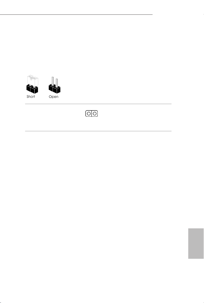
2.5 Jumpers Setup
e illustration shows how jumpers are setup. When the jumper cap is placed on
the pins, the jumper is “Short”. If no jumper cap is placed on the pins, the jumper is
“Open”.
Clear CMOS Jumper
(CLRMO S1)
(see p.1, No. 15)
CLRMOS1 allows you to clear the data in CMOS. To clear and reset the system
parameters to default setup, please turn o the computer and unplug the power
cord from the power supply. Aer waiting for 15 seconds, use a jumper cap to
short the pins on CLRMOS1 for 5 seconds. However, please do not clear the
CMOS right aer you update the BIOS. If you need to clear the CMOS when you
just nish updating the BIOS, you must boot up the system rst, and then shut it
down before you do the clear-CMOS action. Please be noted that the password,
date, time, and user default prole will be cleared only if the CMOS battery is
removed. Please remember toremove the jumper cap aer clearing the CMOS.
2-pin Jumper
H610M-ITX/ac
19
English
Page 24

2.6 Onboard Headers and Connectors
Onboard headers and connectors are NOT jumpers. Do NOT place jumper caps over
these headers and connectors. Placing jumper caps over the headers and connectors
will cause permanent damage to the motherboard.
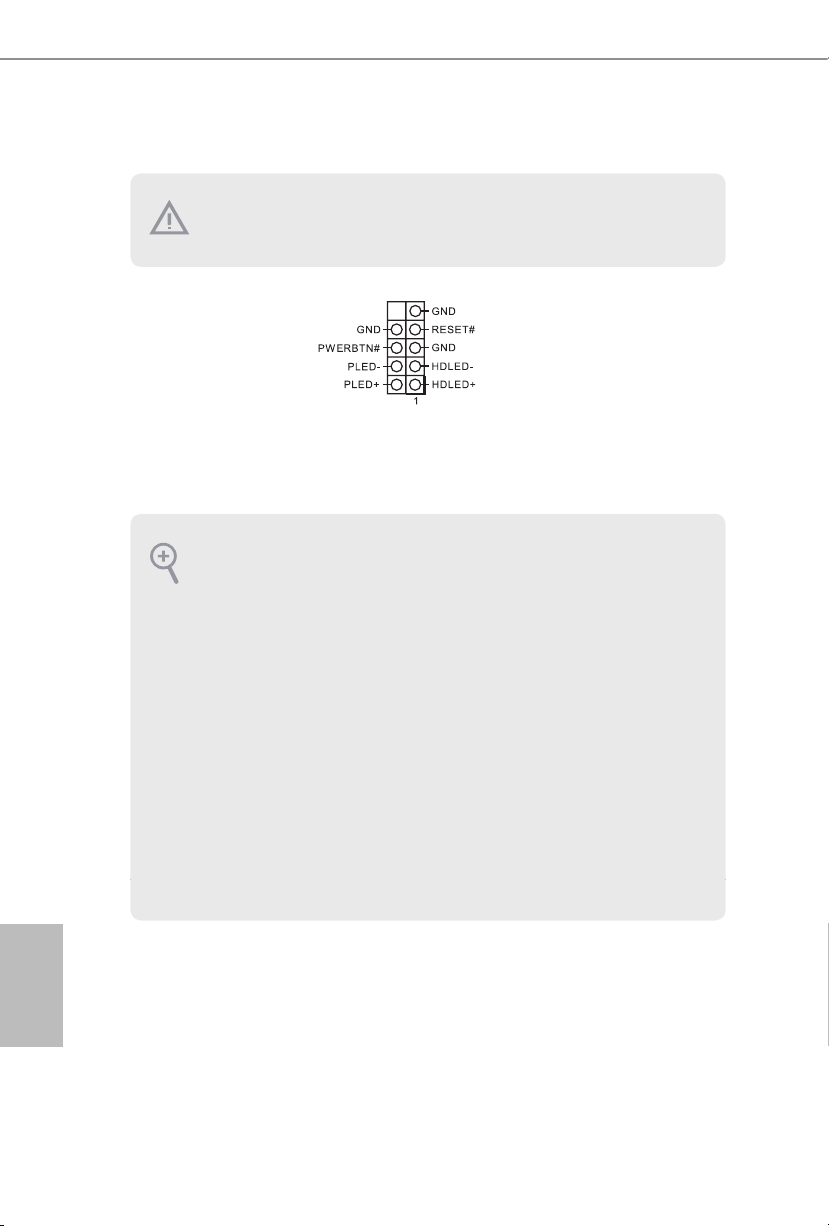
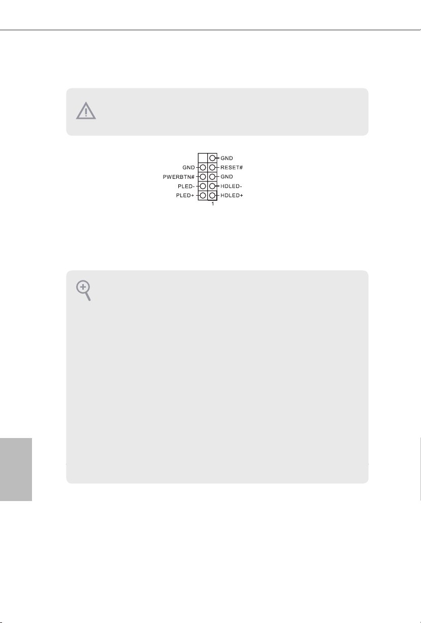
System Panel Header
(9-pi n PANEL1)
(see p.1, No. 13)
PWRBTN (Power Switch):
Connec t to the power switch on the chassi s front panel. You may congure the way to
turn o your system using the power switch.
RESET (Reset Switch):
Connec t to the reset switch on the chassis front panel. Press the reset sw itch to restart
the computer if the compute r freezes and fails to perform a normal restart.
PLED (Syste m Power LED):
Connec t to the power status indicator on the chassis front panel. e LED i s on when
the system is ope rating. e LED keeps blinking when the system i s in S1/S3 sleep
state. e LED is o when the system is in S4 sleep state or powered o (S5).
HDLED (Ha rd Drive Activity LED):
Connec t to the hard drive activity LED on the chassis front panel. e LED is on
when the hard drive i s reading or writing data.
e front panel design may dier by chassis. A front panel module mainly consists
of power switch, reset switch, power LED, hard dr ive activity LED, speak er and etc.
When connecting your chassis front panel module to this head er, make sure the wire
assig nments and the pin assig nments are matched correctly.
Connect the power
switch, reset switch and
system status indicator on
the chassis to this header
according to the pin
assignments below. Note
the positive and negative
pins before connecting
the cables.
English
20
Page 25

H610M-ITX/ac
Serial ATA3 Connectors
(SATA3_0:
see p.1, No. 10)
(SATA3_1:
see p.1, No. 9)
(SATA3_2:
see p.1, No. 12)
(SATA3_3:
see p.1, No. 11)
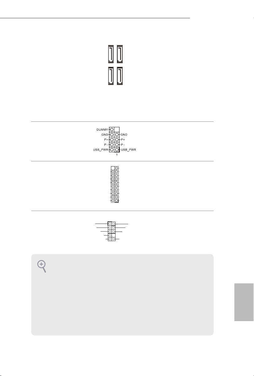
USB 2.0 Header
(9-pin USB_3_4)
(see p.1, No. 14)
USB 3.2 Gen1 Header
(19-pin USB3_3_4)
(see p.1, No. 8)
Front Panel Audio Header
(9-pin HD_ AUDIO1)
(see p.1, No. 17)
IntA_PA_SSRX-
IntA_PA_SSRX+
IntA_PA_SSTX-
IntA_PA_SSTX+
MIC2_L
MIC2_R
OUT2_R
IntA_PA_D-
IntA_PA_D+
J_SENS
OUT2_L
SATA3_1
SATA3_3
Vbus
GND
GND
E
1
VbusVbus
IntA_PB_SSRX-
IntA_PB_SSRX+
GND
IntA_PB_SSTX-
IntA_PB_SSTX+
GND
IntA_PB_D-
IntA_PB_D+
Dummy
1
OUT_RET
SATA3_0
SATA3_2
GND
PRESENCE#
MIC_RET
ese four SATA3
connectors support SATA
data cables for internal
storage devices with up to
6.0 Gb/s data transfer rate.
* If M2_1 is occupied by
a SATA-type M.2 device,
SATA3_0 will be disabled.
ere is one USB2.0
header on this
motherboard. is USB
2.0 header can support
two ports.
ere is one header on
this motherboard. is
USB 3.2 Gen1 header can
support two ports.
is header is for
connecting audio devices
to the front audio panel.
1. High Denition Audio supports Jack Sen sing, but the panel wire on the chassis
must support HDA to function correctly. Please follow the instructions in our
manual and chassis manual to install your system.
2. If you use an AC’97 audio panel, please install it to the front panel audio header by
the steps below:
A. Connect Mic_IN (MIC) to MIC2_ L.
B. Conne ct Audio_R (RIN) to OUT2_R and Audio_ L (LIN) to OUT2_ L.
C. Connect Ground (GND) to Ground (GND).
D. MIC_ RET and OUT_RET are for the HD audio panel only. You don’t need to
connect them for the AC’97 audio panel.
E. To activate the front mic, go to the “FrontMic” Tab in the Realtek Control panel
and adjust “Recording Volume”.
English
21
Page 26

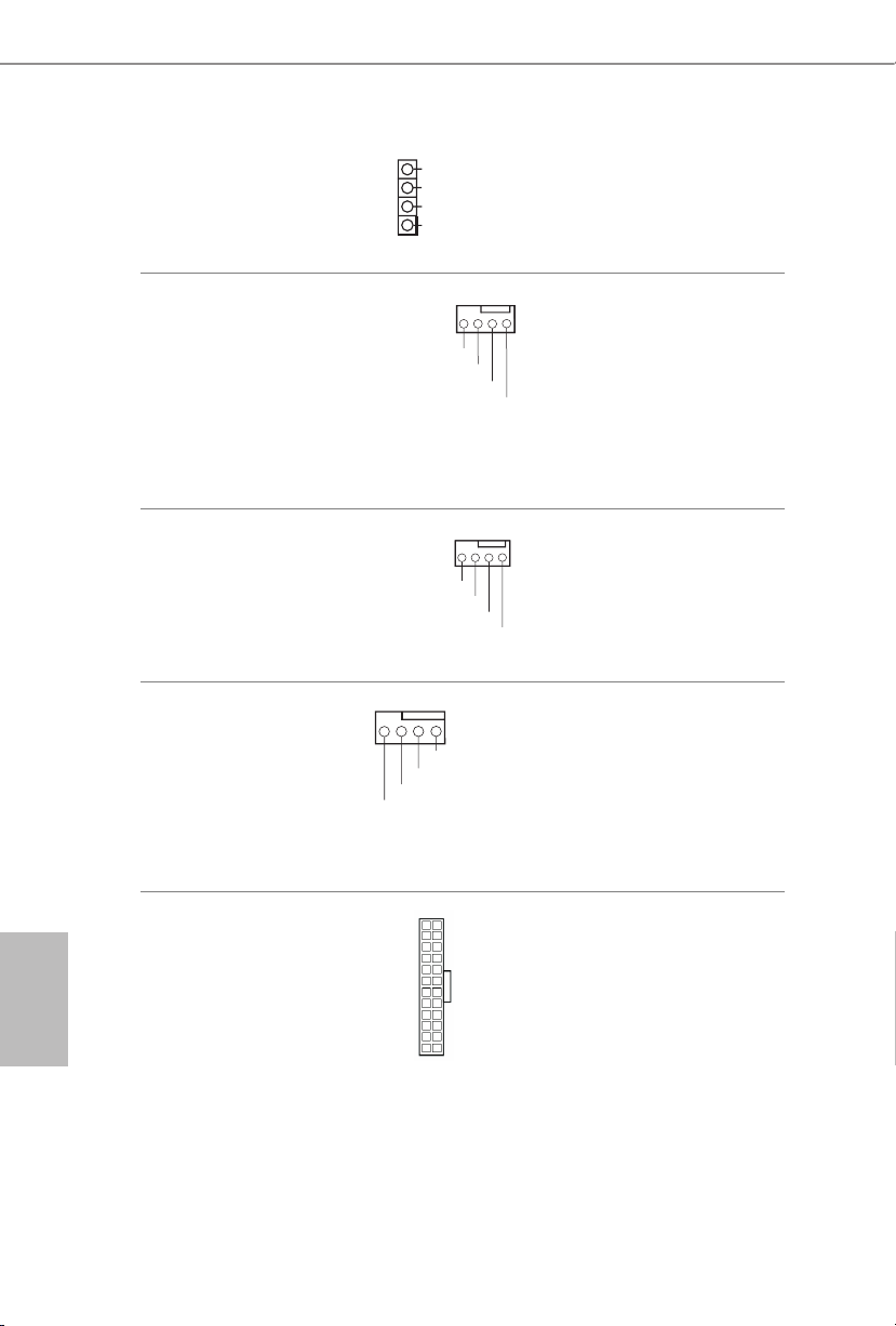
Chassis Speaker Header
4 3 2 1
4 3 2 1
(4-pin SPEAKER1)
(see p.1, No. 16)
1
SPEAKER
DUMMY
DUMMY
+5V
Please connect the chassis
speaker to this header.
Chassis/Water Pump Fan
Connector
(4-pin CHA_FAN1/WP)
(see p.1, No. 4)
Chassis Fan Connector
(4-pin CHA_FAN2)
(see p.1, No. 1)
CPU Fan Connector
(4-pin CPU_FAN1)
(see p.1, No. 3)
ATX Power Connector
(24-pin ATXPWR1)
(see p.1, No. 7)
FAN_SPEED_CONTROL
CHA_FAN_SPEED
FAN_VOLTAGE
FAN_SPEED_CONTROL
CHA_FAN_SPEED
GND
+12V
CPU_F
AN_SPEED
FAN_SPEED_CONTROL
12
4 3 2 1
+12V
24
is motherboard
provides a 4-Pin water
cooling
chassis
connector. If you plan to
connect a 3-Pin
GND
water cooler fan, please
connect it to Pin 1-3.
Please connect fan cables
to the fan connector and
match the black wire to
the ground pin.
GND
is motherboard provides a 4-Pin CPU fan
(Quiet Fan) connector.
If you plan to connect a
3-Pin CPU fan, please
connect it to Pin 1-3.
is motherboard provides a 24-pin ATX power
connector.
fan
chassis
English
22
1
13
Page 27

H610M-ITX/ac
8 5
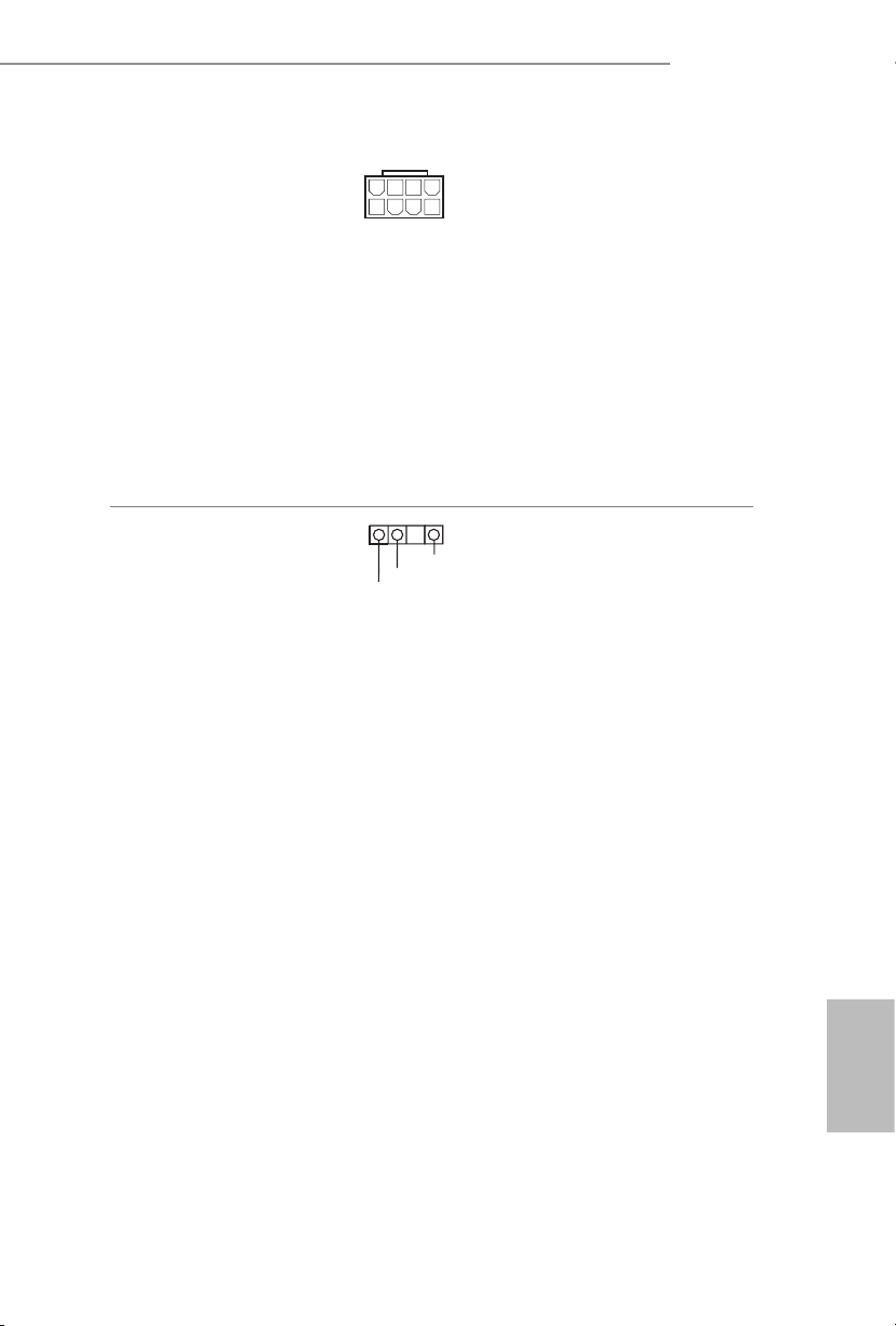
ATX 12V Power
Connector
(8-pin ATX12V1)
(see p.1, No. 2)
Addressable LED Header
(3-pin A DDR_LED1)
(see p.1, No. 5)
4
1
GND
DO_ADDR
VOUT
is motherboard
provides a 8-pin ATX 12V
power connector. To use a
1
4-pin ATX power supply,
please plug it along Pin 1
and Pin 5.
*Warning: Please make
sure that the power cable
connected is for the CPU
and not the graphics
card. Do not plug the
PCIe power cable to this
connector.
is header is used to connect
Addressable
LED extension cable
which allows users to choose
from various LED lighting
eects.
Caution: Never install the
Addressable LED cable in the
wrong orientation; otherwise,
the cable may be damaged.
* Please refer to page 28 for
further instructions on this
header.
English
23
Page 28

2.7 M.2_SSD (NGFF) Module Installation Guide
e M.2, also known as the Next Generation Form Factor (NGFF), is a small size and
versatile card edge connector that aims to replace mPCIe and mSATA. e Ultra M.2
Socket (M2_1, Key M) supports type 2280 SATA3 6.0 Gb/s & PCIe Gen3x4 (32 Gb/s)
modes.
* Please be noted that if M2_1 is occupied by a SATA-type M.2 device, SATA3_0 will be
disabled.
Installing the M.2_SSD (NGFF) Module
Step 1
Prepare a M.2_SSD (NGFF) module
and the screw.
Step 2
Depending on the PCB type and
length of your M.2_SSD (NGFF)
module, nd the corresponding nut
location to be used.
English
24
No. 1
Nut Location A
PCB Length 8cm
Module Type Type 228 0
Page 29

H610M-ITX/ac
Step 3
Align and gently insert the M.2
(NGFF) SSD module into the M.2
slot. Please be aware that the M.2
(NGFF) SSD module only ts in one
A
orientation.
A
o
20
Step 4
Tighten the screw with a screwdriver
to secure the module into place.
Please do not overtighten the screw as
NUT1NUT2
this might damage the module.
English
25
Page 30

English
M.2_SSD (NGFF) Module Support List
Vendor Interface P/N
ADATA SATA3 AXNS330E-32GM-B
ADATA SATA3 AXNS381E-128GM-B
ADATA SATA3 AXNS381E-256GM-B
ADATA SATA3 ASU800NS38-256GT-C
ADATA SATA3 ASU800NS38-512GT-C
ADATA PCIe3 x4 ASX7000NP-128GT-C
ADATA PCIe3 x4 ASX8000NP-256GM-C
ADATA PCIe3 x4 ASX7000NP-256GT-C
ADATA PCIe3 x4 ASX8000NP-512GM-C
ADATA PCIe3 x4 ASX7000NP-512GT-C
Apacer PCIe3 x4 AP240GZ280
Corsair PCIe3 x4 CSSD-F240GBMP500
Crucial SATA3 CT120M500SSD4
Crucial SATA3 CT240M500SSD4
Intel SATA3 Intel SSDSCKGW080A401/80G
Intel PCIe3 x4 SSDPEKKF256G7
Intel PCIe3 x4 SSDPEKKF512G7
Kingston SATA3 SM2280S3
Kingston PCIe3 x4 SKC1000/480G
Kingston PCIe2 x4 SH2280S3/480G
OCZ PCIe3 x4 RVD400-M2280-512G (NVME)
PATR IOT PCIe3 x4 PH240GPM280SSDR NVME
Plextor PCIe3 x4 PX-128M8PeG
Plextor PCIe3 x4 PX-1TM8PeG
Plextor PCIe3 x4 PX-256M8PeG
Plextor PCIe3 x4 PX-512M8PeG
Plextor PCIe PX-G256M6e
Plextor PCIe PX-G512M6e
Samsung PCIe3 x4 SM961 MZVPW128HEGM (NVM)
Samsung PCIe3 x4 PM961 MZVLW128HEGR (NVME)
Samsung PCIe3 x4 960 EVO (MZ-V6E250) (NVME)
Samsung PCIe3 x4 960 EVO (MZ-V6E250BW) (NVME)
Samsung PCIe3 x4 SM951 (NVME)
Samsung PCIe3 x4 SM951 (MZHPV256HDGL)
Samsung PCIe3 x4 SM951 (MZHPV512HDGL)
Samsung PCIe3 x4 SM951 (NVME)
Samsung PCIe x4 XP941-512G (MZHPU512HCGL)
SanDisk PCIe SD6PP4M-128G
SanDisk PCIe SD6PP4M-256G
Team SATA3 TM4PS4128GMC105
Team SATA3 TM4PS4256GMC105
Team SATA3 TM8PS4128GMC105
Team SATA3 TM8PS4256GMC105
26
Page 31

H610M-ITX/ac
TEAM PCIe3 x4 TM8FP2240G0C101
TEAM PCIe3 x4 TM8FP2480GC110
Transcend SATA3 TS256GMTS400
Transcend SATA3 TS512GMTS600
Transcend SATA3 TS512GMTS800
V-Col or SATA3 VLM100-120G-2280B-RD
V-Col or SATA3 VLM10 0-240G-2280RGB
V-Col or SATA3 VSM100 -240G-2280
V-Col or SATA3 VLM10 0-240G-2280B-R D
WD SATA3 WDS100T1B0B-00AS40
WD SATA3 WDS240G1G0B-00RC30
WD PCIe3 x4 WDS256G1X0C-00ENX0 (NVME)
WD PCIe3 x4 WDS512G1X0C-0 0ENX0 (NVME)
For the latest updates of M.2_SSD (NFGG) module support list, please visit our website for
details: http://www.asrock.com
27
English
Page 32

2.8 ASRock Polychrome SYNC
ASRock Polychrome SYNC is a lighting control utility specically designed for unique individuals with sophisticated tastes to build their own stylish colorful lighting system. Simply by
connecting the LED strip, you can customize various lighting schemes and patterns, including
Static, Breathing, Strobe, Cycling, Music, Wave and more.
Connecting the Addressable RGB LED Strip
Connect your
the motherboard.
Addressable RGB LED
RoHS
strips to the
H610M-ITX/ac
Addressable LED Header (ADDR_ LED1)
ADDR_LED1
1
GND
DO_ADDR
VOUT
1
on
English
28
1. Never install the RGB LED cable in the wrong or ientation; otherwise, the cable
may be damaged.
2. Before installing or removing your RGB LED cable, pl ease power o your system
and unplug the power cord from the power supply. Failure to do so may cause damages to motherboard components.
1. Please note that the RGB LED strips do not come with the package .
2. e RGB LED header supports WS2812B addressable RGB LED strip (5V/Data/
GND), with a ma ximum power rating of 3A (5V) and length within 2 meters.
Page 33
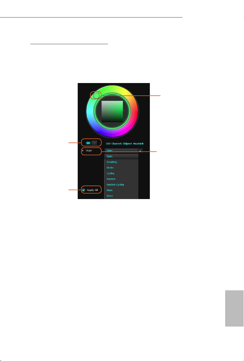
ASRock Polychrome SYNC Utility
Now you can adjust the RGB LED color through the ASRock Polychrome SYNC Utility.
Download this utility from the ASRock Live Update & APP Shop and start coloring your
PC style your way!
Drag the tab to customize your
preference.
Toggle on/o the
RGB LED switch
Sync RGB LED eects
for all LED regions of
the motherboard
Select a RGB LED light eect
from the drop-down menu.
H610M-ITX/ac
29
English
Page 34
1 Einleitung
Vielen Dank, dass Sie sich für das H610M-ITX/ac von ASRock entschieden haben – ein
zuverlässiges Motherboard, das konsequent unter der strengen Qualitätskontrolle von
ASRock hergestellt wurde. Es liefert ausgezeichnete Leistung mit robustem Design, das
ASRock Streben nach Qualität und Beständigkeit erfüllt.
Da die technischen Daten des Motherboards sowie die BIOS-Soware aktualisiert werden
können, kann der Inhalt dieser Dokumentation ohne Ankündigung geändert werden.
Falls diese Dokumentation irgendwelchen Änderungen unterliegt, wird die aktualisierte
Version ohne weitere Hinweise auf der ASRock-Webseite zur Verfügung gestellt. Sollten Sie
technische Hilfe in Bezug auf dieses Motherboard benötigen, erhalten Sie auf unserer Webseite
spezischen Informationen über das von Ihnen verwendete Modell. Auch nden Sie eine
aktuelle Liste unterstützter VGA-Karten und Prozessoren auf der ASRock-Webseite.
ASRock-Webseite http://www.asrock.com.
1.1 Lieferumfang
ASRock H610M-ITX/ac – Motherboard (Mini-ITX-Formfaktor)
•
ASRock H610M-ITX/ac – Schnellinstallationsanleitung
•
ASRock H610M-ITX/ac – Support-CD
•
2 x Serial-ATA- (SATA) Datenkabel (optional)
•
1 x E/A-Blendenabschirmung
•
2 x ASRock-WiFi-2,4/5-GHz-Antennen (optional)
•
1 x Schraube für M.2-Sockel (optional)
•
Deutsch
30
Page 35

1.2 Technische Daten
Mini-ITX-Formfaktor
Plattform
Prozessor
Chipsatz
Speicher
•
Feststoondensator-Design
•
Unterstützt Intel® CoreTM-Prozessoren der 12. Gen. (LGA1700)
•
Digi Power design
•
6-Leistungsphasendesign
•
Unterstützt Intel® Hybrid-Technologie
•
Unterstützt Intel® Turbo Boost Max Technology 3.0
•
Intel® H610
•
Dualkanal-DDR4-Speichertechnologie
•
2 x DDR4-DIMM-Steckplätze
•
Unterstützt ungepuerten DDR4-Non-ECC-Speicher bis 3200*
•
* Weitere Informationen nden Sie in der Speicherkompatibilitätsliste
auf der ASRock-Webseite. (http://www.asrock.com/)
Unterstützt ECC-UDIMM-Speichermodule (Betrieb im non-ECC-
•
Modus)
Systemspeicher, max. Kapazität: 64GB
•
Unterstützt Intel® Extreme Memory Prole (XMP) 2.0
•
H610M-ITX/ac
Erweiterungssteckplatz
Grakkarte
1 x PCIe-Gen4x16-Steckplätze*
•
* Unterstützt NVMe-SSD als Bootplatte
1 x vertikaler M.2-Sockel (Key E), unterstützt Typ-2230-WLAN-/-
•
BT-PCIe-WLAN-Modul und Intel® CNVi (WLAN/BT integriert)
* Integrierte Intel® UHD Graphics-Visualisierung und VGA-Ausgänge
können nur mit Prozessoren unterstützt werden, die GPU-integriert
sind.
Intel® Xe-Grakarchitektur (12. Gen.)
•
Dualer Grakkartenausgang: Unterstützt HDMI- und DisplayPort
•
1.4-Ports durch unabhängige Monitor-Controller
Unterstützt HDMI 2.1 TMDS (komprimiert) mit max. Auösung
•
bis 4K x 2K (4096x2160) bei 60 Hz
Unterstützt DisplayPort 1.4 mit DSC (komprimiert) max.
•
Auösung bis 8K (7680x4320) bei 60 Hz / 5K (5120x3200) bei
120 Hz
Deutsch
31
Page 36

Audio
LAN
Wireless LAN
Rückblende,
E/A
Unterstützt HDCP 2.3 mit TMDS-kompatiblen HDMI-2.1- und
•
DisplayPort-1.4-Ports
7.1-Kanal-HD-Audio (Realtek ALC897-Audiocodec)
•
Unterstützt Überspannungsschutz
•
Gigabit LAN 10/100/1000 Mb/s
•
Giga PHY Intel® I219V
•
Unterstützt Wake-On-LAN
•
Unterstützt Schutz gegen Blitzschlag/elektrostatische Entladung
•
Unterstützt energieezientes Ethernet 802.3az
•
Unterstützt UEFI PXE
•
802.11ac-WLAN-Modul
•
Unterstützt IEEE 802.11a/b/g/n/ac
•
Unterstützt Dualband (2,4/5 GHz)
•
Unterstützt drahtlose Hochgeschwindigkeitsverbindungen bis
•
433 Mb/s
Unterstützt Bluetooth + High-Speed Klasse II
•
2 x Antennenanschluss
•
1 x PS/2-Maus-/Tastaturanschluss
•
1 x HDMI-Port
•
1 x DisplayPort 1.4
•
2 x USB-3.2-Gen1-Ports (unterstützt Schutz gegen elektrostatische
•
Entladung)
2 x USB-2.0-Ports (unterstützt Schutz gegen elektrostatische
•
Entladung)
1 x RJ-45-LAN-Port mit LED (Aktivität/Verbindung-LED und
•
Geschwindigkeit-LED)
HD-Audioanschlüsse: Line-in / Vorderer Lautsprecher / Mikrofon
•
Deutsch
32
Speicher
4 x SATA-III-6,0-Gb/s-Anschlüsse*
•
* Wenn M2_1 durch ein SATA-Typ-M.2-Gerät belegt ist, wird
SATA3_0 deaktiviert.
1 x Ultra-M.2-Sockel (M2_1, Key M), unterstützt Typ-2280-SATA-
•
III-6,0-Gb/s- und PCIe-Gen3x4- (32 Gb/s) Modi**
** Unterstützt Intel® Volume Management Device (VMD)
** Unterstützt NVMe-SSD als Bootplatte
** Unterstützt ASRock U.2-Kit
Page 37

Anschluss
H610M-ITX/ac
1 x Adressierbare-LED-Stileiste
•
* Unterstützt insgesamt bis zu 5 V/3 A, 15-W-LED-Streifen
1 x CPU-Lüeranschluss (4-polig)
•
* Der CPU-Lüeranschluss unterstützt einen CPU-Lüer mit einer
maximalen Lüerleistung von 1 A (12 W).
1 x Gehäuselüeranschluss (4-polig)
•
* Der Gehäuselüeranschluss unterstützt einen Gehäuselüer mit einer
maximalen Lüerleistung von 1 A (12 W).
1 x Anschluss Gehäuse/Wasserpumpenlüer (4-polig) (intelligente
•
Lüergeschwindigkeitssteuerung)
* Der Gehäuse-/Wasserpumpenlüer unterstützt einen
Wasserkühlerlüer mit einer maximalen Lüerleistung von 2 A (24 W).
* CHA_FAN1/WP können automatisch erkennen, ob ein 3- oder
4-poliger Lüer verwendet wird.
1 x 24-poliger ATX-Netzanschluss
•
1 x 8-poliger 12-V-Netzanschluss
•
1 x Audioanschluss an Frontblende
•
1 x USB 2.0-Stileiste (unterstützt zwei USB 2.0-Ports) (unterstützt
•
Schutz gegen elektrostatische Entladung)
1 x USB 3.2 Gen1-Stileiste (unterstützt zwei USB 3.2 Gen1-Ports)
•
(unterstützt Schutz gegen elektrostatische Entladung)
BIOSFunktion
Hardwareüberwachung
AMI-UEFI-Legal-BIOS mit Unterstützung mehrsprachiger
•
grascher Benutzerschnittstellen
ACPI 6.0-konforme Aufweckereignisse
•
SMBIOS 2.7-Unterstützung
•
CPU-Core/Cache, CPU GT, DRAM, VCCIN AUX,
•
+1,05 V PROC, +1,8 V PROC, +0,82 V PCH, +1,05 V PCH /
Mehrfachspannungsanpassung
Lüertachometer: CPU-, Gehäuse-, Gehäuse-/Wasserpumpen-
•
Lüer
Lautloser Lüer (automatische Anpassung der
•
Gehäuselüergeschwindigkeit durch CPU-Temperatur): CPU-,
Gehäuse-, Gehäuse-/Wasserpumpen-Lüer
Mehrfachgeschwindigkeitssteuerung: CPU-, Gehäuse-, Gehäuse-/
•
Wasserpumpen-Lüer
Spannungsüberwachung: CPU Vcore, +12V, +5V, +3,3V, +1,05V
•
PCH
Deutsch
33
Page 38

Microso® Windows® 10 64 Bit / 11 64 Bit
Betriebs-
•
system
FCC, CE
Zertizierungen
* Detaillierte Produktinformationen nden Sie auf unserer Webseite: http://www.asrock.com
•
ErP/EuP ready (ErP/EuP ready-Netzteil erforderlich)
•
Bitte beachten Sie, dass mit einer Übertaktung, zu der die Anpassung von BIOS-Einstellungen,
die Anwendung der Untied Overclocking Technology oder die Nutzung von
Übertaktungswerkzeugen von Drittanbietern zählen, bestimmte Risiken verbunden sind. Eine
Übertaktung kann sich auf die Stabilität Ihres Systems auswirken und sogar Komponenten
und Geräte Ihres Systems beschädigen. Sie sollte auf eigene Gefahr und eigene Kosten
durchgeführt werden. Wir übernehmen keine Verantwortung für mögliche Schäden, die durch
eine Übertaktung verursacht wurden.
Deutsch
34
Page 39
H610M-ITX/ac
1.3 Jumpereinstellung
Die Abbildung zeigt, wie die Jumper eingestellt werden. Wenn die Jumper-Kappe auf den
Kontakten angebracht ist, ist der Jumper „kurzgeschlossen“. Wenn keine Jumper-Kappe auf
den Kontakten angebracht ist, ist der Jumper „oen“.
CMOS-löschen-Jumper
(CLRMOS1)
(siehe S. 1, Nr. 15)
CLRMOS1 ermöglicht Ihnen die Löschung der Daten im CMOS. Zum Löschen und
Rücksetzen der Systemparameter auf die Standardeinrichtung schalten Sie den Computer
bitte ab und ziehen das Netzkabel aus der Steckdose. Warten Sie 15 Sekunde, schließen
Sie dann die Kontakte an CLRMOS1 5 Sekunden lang mit einer Jumper-Kappe kurz.
Löschen Sie den CMOS jedoch nicht direkt nach der BIOS-Aktualisierung. Falls Sie den
CMOS direkt nach Abschluss der BIOS-Aktualisierung löschen müssen, starten Sie das
System zunächst; fahren Sie es dann vor der CMOS-Löschung herunter. Bitte beachten Sie,
dass Kennwort, Datum, Zeit und Benutzerstandardprol nur gelöscht werden, wenn die
CMOS-Batterie entfernt wird. Bitte denken Sie daran, die Jumper-Kappe nach der CMOSLöschung zu entfernen.
2-poliger Jumper
35
Deutsch
Page 40
1.4 Integrierte Stiftleisten und Anschlüsse
Integrierte Stileisten und Anschlüsse sind KEINE Jumper. Bringen Sie KEINE Jumper-Kappen
an diesen Stileisten und Anschlüssen an. Durch Anbringen von Jumper-Kappen an diesen
Stileisten und Anschlüssen können Sie das Motherboard dauerha beschädigen.
Systemblende-Stileiste
(9-polig, PANEL1)
(siehe S. 1, Nr. 13)
PWRBTN (Ein-/Austaste):
Mit der Ein-/Austaste an der Frontblende des Gehäuses verbinden. Sie können die Abschaltung
Ihres Systems über die Ein-/Austaste kongurieren.
RESET (Reset-Taste):
Mit der Reset-Taste an der Frontblende des Gehäuses verbinden. Starten Sie den Computer
über die Reset-Taste neu, wenn er abstürzt oder sich nicht normal neu starten lässt.
PLED (Systembetriebs-LED):
Mit der Betriebsstatusanzeige an der Frontblende des Gehäuses verbinden. Die LED leuchtet,
wenn das System läu. Die LED blinkt, wenn sich das System im S1/S3-Ruhezustand bendet.
Die LED ist aus, wenn sich das System im S4-Ruhezustand bendet oder ausgeschaltet ist (S5).
HDLED (Festplattenaktivitäts-LED):
Mit der Festplattenaktivitäts-LED an der Frontblende des Gehäuses verbinden. Die LED
leuchtet, wenn die Festplatte Daten liest oder schreibt.
Das Design der Frontblende kann je nach Gehäuse variieren. Ein Frontblendenmodul
besteht hauptsächlich aus Ein-/Austaste, Reset-Taste, Betrieb-LED, Festplattenaktivität-LED,
Lautsprecher etc. Stellen Sie beim Anschließen Ihres Frontblendenmoduls an diese Stileiste
sicher, dass Kabel- und Pinbelegung richtig abgestimmt sind.
Verbinden Sie Netzschalter,
Reset-Taste und
Systemstatusanzeige am Gehäuse
entsprechend der nachstehenden
Pinbelegung mit dieser Stileiste.
Beachten Sie vor Anschließen der
Kabel die positiven und negativen
Kontakte.
Deutsch
36
Page 41
H610M-ITX/ac
Serial-ATA-IIIAnschlüsse
(SATA3_0:
siehe S. 1, Nr. 10)
(SATA3_1:
siehe S. 1, Nr. 9)
(SATA3_2:
siehe S. 1, Nr. 12)
(SATA3_3:
siehe S. 1, Nr. 11)
USB 2.0-Stileiste
(9-polig, USB_3_4)
(siehe S. 1, Nr. 14)
USB 3.2 Gen1-Stileiste
(19-polig, USB3_3_4)
(siehe S. 1, Nr. 8)
Audiostileiste
Frontblende
(9-polig, HD_AUDIO1)
(siehe S. 1, Nr. 17)
MIC2_L
MIC2_R
IntA_PA_SSRX-
IntA_PA_SSRX+
IntA_PA_SSTX-
IntA_PA_SSTX+
IntA_PA_D-
IntA_PA_D+
OUT2_R
J_SENS
OUT2_L
SATA3_1
SATA3_3
Vbus
GND
GND
E
1
VbusVbus
IntA_PB_SSRX-
IntA_PB_SSRX+
GND
IntA_PB_SSTX-
IntA_PB_SSTX+
GND
IntA_PB_D-
IntA_PB_D+
Dummy
1
MIC_RET
OUT_RET
SATA3_0
SATA3_2
GND
PRESENCE#
Diese vier SATA-III-Anschlüsse
unterstützen SATA-Datenkabel
für interne Speichergeräte mit
einer Datenübertragungsgeschwi
ndigkeit bis 6,0 Gb/s.
* Wenn M2_1 durch ein SATATyp-M.2-Gerät belegt ist, wird
SATA3_0 deaktiviert.
Es gibt eine USB-2.0-Stileiste an
diesem Motherboard. Diese USB
2.0-Stileiste unterstützt zwei
Ports.
Es gibt eine Stileiste an diesem
Motherboard. Diese USB-3.2Gen1-Stileiste kann zwei Ports
unterstützen.
Diese Stileiste dient dem
Anschließen von Audiogeräten
an der Frontblende.
1. High Denition Audio unterstützt Anschlusserkennung, der Draht am Gehäuse muss dazu
jedoch HDA unterstützt. Bitte befolgen Sie zum Installieren Ihres Systems die Anweisungen
in unserer Anleitung und der Anleitung zum Gehäuse.
2. Bei Nutzung eines AC’97-Audiopanels dieses bitte anhand folgender Schritte an der
Audiostileiste der Frontblende installieren:
A. Mic_IN (Mikrofon) mit MIC2_L verbinden.
B. Audio_R (RIN) mit OUT2_R und Audio_L (LIN) mit OUT2_L verbinden.
C. Erde (GND) mit Erde (GND) verbinden.
D. MIC_RET und OUT_RET sind nur für das HD-Audiopanel vorgesehen. Sie müssen sie
nicht für das AC’97-Audiopanel verbinden.
E. Rufen Sie zum Aktivieren des vorderen Mikrofons das „FrontMic (Vorderes Mikrofon)“Register in der Realtek-Systemsteuerung auf und passen „Recording Volume
(Aufnahmelautstärke)“ an.
Deutsch
37
Page 42

Gehäuselautsprecher-
4 3 2 1
4 3 2 1
4 3 2 1
stileiste
(4-polig, SPEAKER1)
(siehe S. 1, Nr. 16)
1
SPEAKER
DUMMY
DUMMY
+5V
Bitte verbinden Sie den
Gehäuselautsprecher mit dieser
Stileiste.
Gehäuse-/WasserpumpenLüeranschlusse
(4-polig, CHA_FAN1/WP)
(siehe S. 1, Nr. 4)
Gehäuselüeranschluss
(4-polig, CHA_FAN2)
(siehe S. 1, Nr. 1)
CPU-Lüeranschluss
(4-polig, CPU_FAN1)
(siehe S. 1, Nr. 3)
ATX-Netzanschluss
(24-polig, ATXPWR1)
(siehe S. 1, Nr. 7)
FAN_SPEED_CONTROL
CHA_FAN_SPEED
FAN_VOLTAGE
FAN_SPEED_CONTROL
CHA_FAN_SPEED
GND
+12V
CPU_F
AN_SPEED
FAN_SPEED_CONTROL
12
24
+12V
Dieses Motherboard bietet
einen 4-poligen WasserkühlungGehäuselüeranschluss. Falls
Sie einen 3-poligen GehäuseWasserkühlerlüer anschließen
GND
möchten, verbinden Sie ihn bitte
mit Kontakt 1 bis 3.
Bitte verbinden Sie das Lüerkabel
mit dem Lüeranschluss; der
schwarze Draht gehört zum
Erdungskontakt.
GND
Dieses Motherboard bietet einen
4-poligen CPU-Lüeranschluss
(lautloser Lüer). Falls Sie einen
3-poligen CPU-Lüer anschließen
möchten, verbinden Sie ihn bitte
mit Kontakt 1 bis 3.
Dieses Motherboard bietet einen
24-poligen ATX-Netzanschluss.
Deutsch
38
1
13
Page 43
H610M-ITX/ac
8 5
ATX-12-V-Netzanschluss
(8-polig, ATX12V1)
(siehe S. 1, Nr. 2)
Adressierbare-LEDStileiste
(3-polig, ADDR_LED1)
(siehe S. 1, Nr. 5)
4
1
GND
DO_ADDR
VOUT
Dieses Motherboard bietet
einen 8-poligen ATX-12-V-
1
Netzanschluss. Bitte schließen Sie
es zur Nutzung eines 4-poligen
ATX-Netzteils entlang Kontakt 1
und Kontakt 5 an.
*Warnung: Bitte stellen Sie
sicher, dass das Stromkabel der
CPU und nicht das der
Grakkarte angeschlossen ist.
Schließen Sie das PCIe-
Stromkabel nicht an diesen
Anschluss an.
Diese Stileiste dient der
Verbindung des
AdressierbareLED-Verlängerungskabels, womit
Nutzer zwischen verschiedenen
LED-Lichteekten wählen können.
Achtung: Installieren Sie das
Adressierbare-LED-Kabel
niemals falsch herum; andernfalls
könnte das Kabel beschädigt
werden.
*Weitere Anweisungen zu dieser
Stileiste nden Sie auf Seite 28.
Deutsch
39
Page 44

1 Introduction
Nous vous remercions d’avoir acheté cette carte mère ASRock H610M-ITX/ac, une carte
mère able fabriquée conformément au contrôle de qualité rigoureux et constant appliqué
par ASRock. Fidèle à son engagement de qualité et de durabilité, ASRock vous garantit une
carte mère de conception robuste aux performances élevées.
Les spécications de la carte mère et du logiciel BIOS pouvant être mises à jour, le contenu
de ce document est soumis à modication sans préavis. En cas de modications du présent
document, la version mise à jour sera disponible sur le site Internet ASRock sans notication
préalable. Si vous avez besoin d’une assistance technique pour votre carte mère, veuillez visiter
notre site Internet pour plus de détails sur le modèle que vous utilisez. La liste la plus récente
des cartes VGA et des processeurs pris en charge est également disponible sur le site Internet de
ASRock. Site Internet ASRock http://www.asrock.com.
1.1 Contenu de l’emballage
Carte mère ASRock H610M-ITX/ac (facteur de forme Mini-ITX)
•
Guide d’installation rapide ASRock H610M-ITX/ac
•
CD d’assistance ASRock H610M-ITX/ac
•
2 x câbles de données Serial ATA (SATA) (Optionnel)
•
1 x panneau de protection E/S
•
2 x antenne Wi-Fi 2,4/5 GHz ASRock (Optionnel)
•
1 x vis pour socket M.2 (Optionnel)
•
Français
40
Page 45

1.2 Spécications
Facteur de forme Mini-ITX
Plateforme
•
Conception à condensateurs solides
•
H610M-ITX/ac
Processeur
Chipset
Mémoire
Fente
d’expansion
Prend en charge les processeurs 12
•
(LGA1700)
Digi Power design
•
Alimentation à 6 phases
•
Prend en charge Intel® Hybrid Technology
•
Prend en charge la technologie Intel® Turbo Boost Max 3.0
•
Intel® H610
•
Technologie mémoire double canal DDR4
•
2 x fentes DIMM DDR4
•
Prise en charge des mémoires DDR4 non-ECC, sans tampon et
•
jusqu'à 3200*
* Veuillez consulter la liste de prise en charge des mémoires sur le site
Web d'ASRock pour de plus amples informations.
(http://www.asrock.com/)
Prend en charge les modules mémoire UDIMM ECC (fonctionne
•
en mode non-ECC)
Capacité max. de la mémoire système : 64GO
•
Prend en charge Intel® Extreme Memory Prole (XMP) 2.0
•
1 x fente PCIe Gen4x16*
•
* Prend en charge les SSD NVMe comme disques de démarrage
1 x socket M.2 vertical (Touche E), prend en charge les
•
emplacements modules WiFi/BT type 2230, WiFi PCIe et Intel®
CNVi (WiFi/BT intégré)
ème
génération Intel® CoreTM
Graphiques
* La technologie Intel® UHD Graphics Built-in Visuals et les sorties
VGA sont uniquement prises en charge par les processeurs intégrant
un contrôleur graphique.
Architecture graphique Intel® Xe (Gen 12)
•
Double sortie graphique: Prend en charge les ports HDMI et
•
DisplayPort 1.4 via contrôleurs d’achage indépendants
Prend en charge la technologie HDMI 2.1 TMDS Compatible avec
•
résolution maximale de 4K x 2K (4096x2160) @ 60Hz
Prend en charge DisplayPort 1.4 avec résolution max. DSC
•
(compressée) jusqu’à 8K (7680x4320) @ 60 Hz / 5K (5120x3200) @
120 Hz
Français
41
Page 46

Audio
Réseau
Réseau
sans-l
Connectique
du panneau
arrière
Prend en charge HDCP 2.3 avec ports HDMI 2.1 compatibles
•
TMDS et DisplayPort 1.4
Audio 7.1 CH HD (Codec audio Realtek ALC897)
•
Prend en charge la protection contre les surtensions
•
Gigabit LAN 10/100/1000 Mo/s
•
Giga PHY Intel® I219V
•
Prend en charge la fonction Wake-On-LAN
•
Prend en charge la protection contre la foudre/les décharges
•
électrostatiques
Prend en charge la fonction d’économie d’énergie Ethernet 802.3az
•
Prend en charge UEFI PXE
•
Module Wi-Fi 802.11ac
•
Prend en charge IEEE 802.11a/b/g/n/ac
•
Prend en charge le mode Dual-Band (2,4/5 GHz)
•
Prend en charge la connexion sans-l à haute vitesse jusqu’à
•
433Mbps
Prend en charge Bluetooth + classe II haut débit
•
2 x ports antenne
•
1 x port souris/clavier PS/2
•
1 x port HDMI
•
1 x DisplayPort 1.4
•
2 x ports USB 3.2 Gen1 (Protection contre les décharges
•
électrostatiques)
2 x ports USB 2.0 (Protection contre les décharges électrostatiques)
•
1 x port RJ-45 LAN avec LED (LED ACT/LIEN et LED VITESSE)
•
Connecteurs jack audio HD : Entrée ligne / haut-parleur avant /
•
microphone
Français
42
Stockage
4 x connecteurs SATA3 6,0 Go/s*
•
* Si M2_1 est occupé par un périphérique M.2 type SATA, SATA3_0 est
désactivé.
1 x Socket Ultra M.2 (M2_1, Key M), supporte les modes SATA3
•
6,0 Go/s et PCIe Gen3x4 (32 Go/s) de type 2280**
** Prend en charge Intel® Volume Management Device (VMD)
** Prend en charge les SSD NVMe comme disques de démarrage
** Prend en charge le kit ASRock U.2
Page 47

Connecteur
H610M-ITX/ac
1 x embase LED adressable
•
* Prend en charge les rubans LED jusqu'à 5 V/3 A, 15 W au total
1 x connecteur pour ventilateur de CPU (4 broches)
•
* Le connecteur pour ventilateur de CPU prend en charge un
ventilateur de CPU d'une puissance maximale de 1 A (12 W).
1 x connecteur pour ventilateur de châssis (4 broches)
•
* Le connecteur pour ventilateur de châssis prend en charge un
ventilateur de châssis d'une puissance maximale de 1 A (12 W).
1 x connecteur pour ventilateur de châssis /pompe à eau (4 broches)
•
(contrôle de vitesse de ventilateur intelligent)
* Le ventilateur de châssis /pompe à eau prend en charge un ventilateur
de refroidisseur d'eau d'une puissance maximale de 2 A (24 W).
* CHA_FAN1/WP peuvent détecter automatiquement si un ventilateur
3 broches ou 4 broches est utilisé.
1 x connecteur d’alimentation ATX 24 broches
•
1 x connecteur d’alimentation 12V 8 broches
•
1 x connecteur audio panneau frontal
•
1 x embase USB 2.0 (2 ports USB 2.0 pris en charge) (Protection
•
contre les décharges électrostatiques)
1 x embase USB 3.2 Gen1 (2 ports USB 3.2 Gen1 pris en charge)
•
(Protection contre les décharges électrostatiques)
Caractéristiques du
BIOS
Surveillance
du matériel
Système
d’exploitation
BIOS UEFI AMI avec prise en charge d’interface graphique
•
multilingue
Compatible ACPI 6.0 Wake Up Events
•
Compatible SMBIOS 2.7
•
Réglage de la tension CPU Core/Cache, GT, DRAM, VCCIN AUX,
•
+1,05V PROC, +1,8V PROC, +0,82V PCH, +1,05V PCH
Tachymètre de ventilateur : Ventilateurs de CPU, châssis, châssis /
•
pompe à eau
Ventilateur silencieux (réglage automatique de la vitesse du
•
ventilateur du châssis d’après la température du CPU) : Ventilateurs
de CPU, châssis, châssis / pompe à eau
Contrôle simultané des vitesses du ventilateur : Ventilateurs de
•
CPU, châssis, châssis / pompe à eau
Surveillance de la tension d’alimentation : CPU Vcore, +12V, +5V,
•
+3,3V, +1,05V PCH
Microso® Windows® 10 64-bits / 11 64-bits
•
Français
43
Page 48
FCC, CE
Certications
* pour des informations détaillées de nos produits, veuillez visiter notre site: http://www.asrock.com
•
ErP/EuP Ready (alimentation ErP/EuP ready requise)
•
Il est important de signaler que l’overclocking présente certains risques, incluant des
modications du BIOS, l’application d’une technologie d’overclocking déliée et l’utilisation
d’outils d’overclocking développés par des tiers. La stabilité de votre système peut être aectée
par ces pratiques, voire provoquer des dommages aux composants et aux périphériques du
système. L’overclocking se fait à vos risques et périls. Nous ne pourrons en aucun cas être tenus
pour responsables des dommages éventuels provoqués par l’overclocking.
Français
44
Page 49

H610M-ITX/ac
1.3 Conguration des cavaliers (jumpers)
L’illustration ci-dessous vous renseigne sur la conguration des cavaliers (jumpers). Lorsque
le capuchon du cavalier est installé sur les broches, le cavalier est «court-circuité». Si le
capuchon du cavalier n’est pas installé sur les broches, le cavalier est «ouvert».
Cavalier Clear CMOS
(CLRMOS1)
(voir p.1, No. 15)
CLRMOS1 vous permet d’eacer les donnés de la CMOS. Pour eacer les paramètres du
système et rétablir les valeurs par défaut, veuillez éteindre votre ordinateur et débrancher
son cordon d’alimentation. Patientez 15 secondes, puis utilisez un capuchon de cavalier
pour court-circuiter les broches sur CLRMOS1 pendant 5 secondes. Toutefois, n’eacez
pas la CMOS immédiatement après avoir mis à jour le BIOS. Si vous avez besoin d’eacer
les données CMOS après une mise à jour du BIOS, vous devez tout d’abord redémarrer le
système, puis l’éteindre avant de procéder à l’eacement de la CMOS. Veuillez noter que les
paramètres mot de passe, date, heure et prol de l’utilisateur seront uniquement eacés en
cas de retrait de la pile de la CMOS. N’oubliez pas de retirer le capuchon du cavalier une
fois les données CMOS eacées.
Cavalier (jumper) à
2 broches
45
Français
Page 50
1.4 Embases et connecteurs de la carte mère
Les embases et connecteurs situés sur la carte NE SONT PAS des cavaliers. Ne placez JAMAIS
de capuchons de cavaliers sur ces embases ou connecteurs. Placer un capuchon de cavalier sur
ces embases ou connecteurs endommagera irrémédiablement votre carte mère.
Français
Embase du panneau
système
(PANNEAU1 à 9 broches)
(voir p.1, No. 13)
PWRBTN (bouton d’alimentation):
pour brancher le bouton d’alimentation du panneau frontal du châssis. Vous pouvez congurer
la façon dont votre système doit s’arrêter à l’aide du bouton de mise en marche.
RESET (bouton de réinitialisation):
pour brancher le bouton de réinitialisation du panneau frontal du châssis. Appuyez
sur le bouton de réinitialisation pour redémarrer l’ordinateur en cas de plantage ou de
dysfonctionnement au démarrage.
PLED (LED d’alimentation du système) :
pour brancher le témoin d’état de l’alimentation du panneau frontal du châssis. Le LED est
allumé lorsque le système fonctionne. Le LED clignote lorsque le système se trouve en mode
veille S1/S3. Le LED est éteint lorsque le système se trouve en mode veille S4 ou hors tension (S5).
HDLED (LED d’activité du disque dur) :
pour brancher le témoin LED d’activité du disque dur du panneau frontal du châssis. Le LED
est allumé lorsque le disque dur lit ou écrit des données.
La conception du panneau frontal peut varier en fonction du châssis. Un module de panneau
frontal est principalement composé d’un bouton de mise en marche, bouton de réinitialisation,
LED d’alimentation, LED d’activité du disque dur, haut-parleur etc. Lorsque vous reliez le
module du panneau frontal de votre châssis sur cette embase, veillez à parfaitement faire
correspondre les ls et les broches.
Branchez le bouton de mise
en marche, le bouton de
réinitialisation et le témoin d’état
du système présents sur le châssis
sur cette embase en respectant la
conguration des broches illustrée
ci-dessous. Repérez les broches
positive et négative avant de
brancher les câbles.
46
Page 51

H610M-ITX/ac
Connecteurs Serial ATA3
(SATA3_0:
voir p.1, No. 10)
(SATA3_1:
voir p.1, No. 9)
(SATA3_2:
voir p.1, No. 12)
(SATA3_3:
voir p.1, No. 11)
Embase USB 2.0
(USB_3_4 à 9 broches)
(voir p.1, No. 14)
Embase USB 3.2 Gen1
(USB3_3_4 à 19 broches)
(voir p.1, No. 8)
Embase audio du panneau
frontal
(HD_AUDIO1 à 9 broches)
(voir p.1, No. 17)
MIC2_L
MIC2_R
OUT2_R
SATA3_1
SATA3_3
IntA_PA_SSRX-
IntA_PA_SSRX+
IntA_PA_SSTX-
IntA_PA_SSTX+
IntA_PA_D-
IntA_PA_D+
J_SENS
E
OUT2_L
Vbus
GND
GND
1
VbusVbus
IntA_PB_SSRX-
IntA_PB_SSRX+
GND
IntA_PB_SSTX-
IntA_PB_SSTX+
GND
IntA_PB_D-
IntA_PB_D+
Dummy
1
MIC_RET
OUT_RET
Ces quatre connecteurs SATA3
sont compatibles avec les câbles de
SATA3_0
données SATA pour les appareils
de stockage internes avec un taux
de transfert maximal de 6,0 Go/s.
SATA3_2
* Si M2_1 est occupé par un
périphérique M.2 type SATA,
SATA3_0 est désactivé.
Cette carte mère comprend un
connecteur USB2.0. Cette embase
USB 2.0 peut prendre en charge
deux ports.
Cette carte mère comprend un
connecteur. Cette embase USB 3.2
Gen1 peut prendre en charge deux
ports.
Cette embase sert au branchement
GND
des appareils audio au panneau
PRESENCE#
audio frontal.
1. L’audio haute dénition prend en charge la technologie Jack Sensing (détection de la che),
mais le panneau grillagé du châssis doit être compatible avec la HDA pour fonctionner
correctement. Veuillez suivre les instructions gurant dans notre manuel et dans le manuel
du châssis pour installer votre système.
2. Si vous utilisez un panneau audio AC’97, veuillez le brancher sur l’embase audio du panneau
frontal en procédant comme suit :
A. branchez Mic_IN (MIC) sur MIC2_L.
B. branchez Audio_R (RIN) sur OUT2_R et Audio_L (LIN) sur OUT2_L.
C. branchez la mise à terre (GND) sur mise à terre (GND).
D. MIC_RET et OUT_RET sont exclusivement réservés au panneau audio HD. Il est inutile
de les brancher avec le panneau audio AC’97.
E. Pour activer le micro frontal, sélectionnez l’onglet «FrontMic» du panneau de contrôle
Realtek et réglez le paramètre «Volume d’enregistrement».
Français
47
Page 52
Embase du haut-parleur du
4 3 2 1
4 3 2 1
4 3 2 1
châssis
(SPEAKER1 à 4 broches)
(voir p.1, No. 16)
1
SPEAKER
DUMMY
DUMMY
+5V
Veuillez brancher le haut-parleur
du châssis sur cette embase.
Français
Connecteurs du ventilateur
de châssis/pompe à eau
(CHA_FAN1/WP à
4 broches)
(voir p.1, No. 4)
Connecteur du ventilateur
du châssis
(CHA_FAN2 à 4 broches)
(voir p.1, No. 1)
Connecteur du ventilateur
du processeur
(CPU_FAN1 à 4 broches)
(voir p.1, No. 3)
Connecteur d’alimentation
ATX
(ATXPWR1 à 24 broches)
(voir p.1, No. 7)
FAN_SPEED_CONTROL
CHA_FAN_SPEED
FAN_VOLTAGE
FAN_SPEED_CONTROL
CHA_FAN_SPEED
GND
+12V
CPU_F
AN_SPEED
FAN_SPEED_CONTROL
12
24
+12V
Cette carte mère est dotée d’un
connecteur pour ventilateur de
châssis à refroidissement par eau
à 4 broches. Si vous envisagez
de connecter un ventilateur de
GND
refroidisseur d'eau pour châssis à
3 broches, veuillez le brancher sur
la Broche 1-3.
Veuillez brancher les câbles du
ventilateur sur le connecteur du
ventilateur, puis reliez le l noir à
la broche de mise à terre.
GND
Cette carte mère est dotée d’un
connecteur pour ventilateur de
processeur (Quiet Fan) à
4 broches. Si vous envisagez
de connecter un ventilateur de
processeur à 3 broches, veuillez le
brancher sur la broche 1-3.
Cette carte mère est dotée d’un
connecteur d’alimentation ATX à
24 broches.
48
1
13
Page 53

H610M-ITX/ac
8 5
Connecteur d’alimentation
ATX 12 V
(ATX12V1 à 8 broches)
(voir p.1, No. 2)
Embase LED adressable
(ADDR_LED1 à 3 broches)
(voir p.1, No. 5)
4
1
GND
DO_ADDR
VOUT
Cette carte mère est dotée d’un
connecteur d’alimentation ATX
12 V à 8 broches. Pour utiliser une
1
alimentation ATX à 4 broches,
veuillez eectuer les branchements
sur la Broche 1 et la Broche 5.
*Avertissement : Veuillez vérier
que le câble d'alimentation
connecté est pour l'unité
centrale et non pour la carte
graphique. Ne branchez pas le
câble d'alimentation PCIe sur ce
connecteur.
Cette embase sert à connecter un
câble de rallonge LED
permettant aux utilisateurs de
choisir parmi diérents eets
lumineux LED.
Attention : N’installez jamais
le câble LED adressable dans
le mauvais sens. Dans le cas
contraire, le câble peut être
endommagé.
* Veuillez consulter la page 28 pour
des instructions supplémentaires
sur cette embase.
adressable
Français
49
Page 54

1 Introduzione
Congratulazioni per l’acquisto della scheda madre ASRock H610M-ITX/ac, una scheda
madre adabile prodotta secondo i severissimi controlli di qualità ASRock. La scheda madre
ore eccellenti prestazioni con un design robusto che si adatta all'impegno di ASRock di
orire sempre qualità e durata.
Dato che le speciche della scheda madre e del soware BIOS possono essere aggiornate, il
contenuto di questa documentazione sarà soggetto a variazioni senza preavviso. Nel caso di
eventuali modiche della presente documentazione, la versione aggiornata sarà disponibile sul
sito Web di ASRock senza ulteriore preavviso. Per il supporto tecnico correlato a questa scheda
madre, visitare il nostro sito Web per informazioni speciche relative al modello attualmente
in uso. È possibile trovare l'elenco di schede VGA più recenti e di supporto di CPU anche sul
sito Web di ASRock. Sito Web di ASRock http://www.asrock.com.
1.1 Contenuto della confezione
Scheda madre ASRock H610M-ITX/ac (Form Factor Mini-ITX)
•
Guida all'installazione rapida di ASRock H610M-ITX/ac
•
CD di supporto di ASRock H610M-ITX/ac
•
2 x cavi dati Serial ATA (SATA) (opzionali)
•
1 x mascherina metallica posteriore I/O
•
2 x antenne ASRock WiFi da 2,4/5 GHz (opzionali)
•
1 x viti per Socket M.2 (opzionali)
•
Italiano
50
Page 55

1.2 Speciche
Piattaforma
CPU
Chipset
Memoria
H610M-ITX/ac
Fattore di forma Mini-ITX
•
Design condensatore solido
•
Supporta processori 12th Generation Intel® CoreTM (LGA1700)
•
Digi Power design
•
Potenza a 6 fasi
•
Supporta la tecnologia Intel® Hybrid
•
Supporta la tecnologia Intel® Turbo Boost Max 3.0
•
Intel® H610
•
Tecnologia memoria DDR4 Dual Channel
•
2 x alloggi DIMM DDR4
•
Supporta memoria DDR4 non ECC, senza buer no a 3200*
•
* Per maggiori informazioni fare riferimento all'elenco dei supporti di
memoria sul sito di ASRock. (http://www.asrock.com/)
Supporta moduli di memoria ECC UDIMM (funziona in modalità
•
non ECC)
Capacità max. della memoria di sistema: 64GB
•
Supporto di XMP (Extreme Memory Prole) Intel® 2.0
•
Alloggio
d’espansione
Graca
1 x alloggi PCIe Gen4x16*
•
* Supporto di SSD NVMe come disco d’avvio
1 x Socket M.2 verticale (Key E), supporta il modulo WiFi tipo
•
2230 WiFi/BT PCIe e Intel® CNVi (Integrated WiFi/BT)
* La videograca integrata della scheda video UHD Intel® e le uscite
VGA possono essere supportate soltanto con processori con GPU
integrata.
Architettura graca Intel® Xe (Gen 12)
•
Doppia uscita graca: supporto di porte HDMI e DisplayPort 1.4
•
tramite controller display indipendenti
Supporta HDMI 2.1 compatibile TMDS con risoluzione massima
•
no a 4K x 2K (4096 x 2160) a 60 Hz
Supporta DisplayPort 1.4 con DSC (compresso) risoluzione max.
•
no a 8K (7680 x 4320) a 60 Hz / 5K (5120 x 3200) a 120 Hz
Italiano
51
Page 56

Italiano
Audio
LAN
LAN wireless
I/O pannello
posteriore
Supporta HDCP 2.3 con HDMI 2.1 compatibile TMDS e porte
•
DisplayPort 1.4
Audio HD 7.1 CH (codec audio Realtek ALC897)
•
Supporta protezione da sovratensione
•
LAN Gigabit 10/100/1000 Mb/s
•
Giga PHY Intel® I219V
•
Supporto WOL (Wake-On-LAN)
•
Supporta protezione da fulmini/scariche elettrostatiche
•
Supporto Energy Ecient Ethernet 802.3az
•
Supporto UEFI PXE
•
Modulo WiFi 802.11ac
•
Supporta IEEE 802.11a/b/g/n/ac
•
Supporta Dual-Band (2,4/5 GHz)
•
Supporta la connessione wireless ad alta velocità no a 433 Mbps
•
Supporto di Bluetooth + High speed Classe II
•
2 x porte antenna
•
1 x porta mouse/tastiera PS/2
•
1 x porta HDMI
•
1 x DisplayPort 1.4
•
2 x porte USB 3.2 Gen1 (supporto protezione da scariche
•
elettrostatiche)
2 x porte USB 2.0 (supporto protezione da scariche elettrostatiche)
•
1 x porta LAN RJ-45 con LED (ACT/LINK LED e SPEED LED)
•
Connettori audio HD: Ingresso linea / altoparlante frontale /
•
microfono
52
Archiviazione
4 x Connettori SATA3 6,0 Gb/s*
•
* Se M2_1 è occupato da un dispositivo M.2 di tipo SATA, SATA3_0
sarà disabilitato.
1 x socket Ultra M.2 (M2_1, key M), supporta le modalità di tipo
•
2280 SATA3 6,0 Gb/s e PCIe Gen3x4 (32 Gb/s)**
** Supporta il dispositivo di gestione del volume Intel® (VMD)
** Supporto di SSD NVMe come disco d’avvio
** Supporta kit ASRock U.2
Page 57

Connettore
H610M-ITX/ac
1 x Header LED indirizzabile
•
* Supporto totale di no a 5V/3A, 15W strip LED
1 x connettore ventola CPU (4-pin)
•
* Il connettore ventola CPU supporta ventole CPU con potenza
massima di 1 A (12 W).
1 x Connettore ventola telaio (4-pin)
•
* Il connettore ventola telaio supporta ventole telaio con potenza
massima di 1 A (12 W).
1 x connettore ventola chassis/ventola pompa dell’acqua (4 pin)
•
(Controllo intelligente della velocità della ventola)
* La ventola Chassis/ventola pompa dell’acqua supporta ventole di
sistemi di rareddamento ad acqua di potenza massima di 2 A (24W).
* CHA_FAN1WP sono in grado di rilevare se è in uso una ventola a
3 pin o 4 a pin.
1 x connettore alimentazione ATX 24-pin
•
1 x connettore alimentazione 12 V 8-pin
•
1 x connettore audio pannello frontale
•
1 x connettore USB 2.0 (supporto di 2 porte USB 2.0) (supporto
•
protezione da scariche elettrostatiche)
1 x connettore USB 3.2 Gen1 (supporto di 2 porte USB 3.2 Gen1)
•
(supporto protezione da scariche elettrostatiche)
Funzionalità
BIOS
Hardware
Monitor
SO
AMI UEFI Legal BIOS con interfaccia di supporto multilingue
•
Eventi di riattivazione conformi a ACPI 6.0
•
Supporto di SMBIOS 2.7
•
CPU Core/Cache, CPU GT, DRAM, VCCIN AUX, +1,05 V PROC,
•
+1,8 V PROC, + 0,82 V PCH, Regolazione multipla della tensione
+1,05 V PCH
Tachimetro ventola: Ventole CPU, chassis, chassis/pompa dell’acqua
•
Ventola silenziosa (regolazione automatica velocità in base alla
•
temperatura della CPU): Ventole CPU, chassis, chassis/pompa
dell’acqua
Controllo velocità ventola: Ventole CPU, chassis, chassis/pompa
•
dell’acqua
Monitoraggio tensione: CPU Vcore, +12V, +5V, +3,3V, +1,05V
•
PCH
Microso® Windows® 10 64 bit / 11 64 bit
•
Italiano
53
Page 58

FCC, CE
Certicazioni
* Per informazioni dettagliate sul prodotto, visitare il nostro sito Web: http://www.asrock.com
•
ErP/EuP Ready (è necessaria alimentazione ErP/EuP ready)
•
Prestare attenzione al potenziale rischio previsto nella pratica di overclocking, inclusa la
regolazione delle impostazioni nel BIOS, l'applicazione di tecnologia di Untied Overclocking o
l'utilizzo di strumenti di overclocking di terze parti. L'overclocking può inuenzare la stabilità
del sistema o perno provocare danni ai componenti e ai dispositivi del sistema. Occorre
eseguirlo a proprio rischio e spese. Non ci riterremo responsabili per possibili danni provocati
da overclocking.
Italiano
54
Page 59
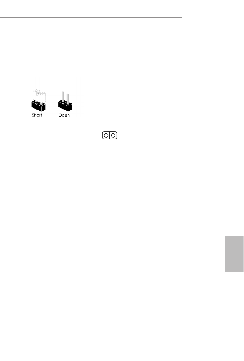
H610M-ITX/ac
1.3 Impostazione jumper
L'illustrazione mostra in che modo vengono impostati i jumper. Quando il cappuccio del
jumper è posizionato sui pin, il jumper è "cortocircuitato". Se sui pin non è posizionato alcun
cappuccio del jumper, il jumper è "aperto".
Jumper per azzerare la
CMOS
(CLRMOS1)
(vedere pag. 1, n. 15)
CLRMOS1 permette si azzerare i dati nella CMOS. Per azzerare e reimpostare i parametri
del sistema alla congurazione predenita, spegnere il computer e scollegare il cavo di
alimentazione dalla rete. Attendere 15 secondi, quindi usare un cappuccio jumper per
cortocircuitare i di CLRMOS1 per 5 secondi. Tuttavia, non azzerare la CMOS subito dopo
aver aggiornato il BIOS. Se è necessario azzerare la CMOS dopo l'aggiornamento del BIOS,
è necessario riavviare prima il sistema e in seguito spegnerlo prima di eseguire l'operazione
di azzeramento della CMOS. La password, la data, l'ora e il prolo predenito dell'utente
saranno azzerati solo se viene rimossa la batteria della CMOS. Ricordarsi di rimuovere il
cappuccio jumper prima di cancellare la CMOS.
Jumper a 2 pin
55
Italiano
Page 60

1.4 Header e connettori su scheda
Gli header e i connettori sulla scheda NON sono jumper. NON posizionare cappucci del
jumper su questi header e connettori. Il posizionamento di cappucci del jumper su header e
connettori provocherà danni permanenti alla scheda madre.
Italiano
Header sul pannello del
sistema
(PANEL1 a 9 pin)
(vedere pag. 1, n. 13)
PWRBTN (interruttore di alimentazione):
collegare all'interruttore dell'alimentazione sul pannello anteriore dello chassis. È possibile
congurare il modo in cui spegnere il sistema utilizzando l'interruttore dell'alimentazione.
RESET (interruttore di reset):
collegare all'interruttore di reset sul pannello anteriore dello chassis. Premere l'interruttore
di reset per riavviare il computer se il computer si blocca e non riesce ad eseguire un normale
riavvio.
PLED (LED alimentazione del sistema):
collegare all'indicatore di stato dell'alimentazione sul pannello anteriore dello chassis. Il LED
è acceso quando il sistema è in funzione. Il LED continua a lampeggiare quando il sistema si
trova nello stato di sospensione S1/S3. Il LED è spento quando il sistema si trova nello stato di
sospensione S4 o quando è spento (S5).
HDLED (LED di attività disco rigido):
collegare al LED di attività disco rigido sul pannello anteriore dello chassis. Il LED è acceso
quando il disco rigido sta leggendo o scrivendo dati.
Il design del pannello anteriore può cambiare a seconda dello chassis. Un modulo di pannello
anteriore è composto principalmente da interruttore di alimentazione, interruttore di reset,
LED di alimentazione, LED di attività disco rigido, altoparlante, ecc. Quando si collega il
modulo del pannello anteriore dello chassis a questo header, accertarsi che le assegnazioni del
lo e le assegnazioni del pin corrispondano correttamente.
Collegare l'interruttore
dell'alimentazione, l'interruttore
di reset e l'indicatore dello stato
del sistema sullo chassis su questo
header secondo la seguente
assegnazione dei pin. Annotare
i pin positivi e negativi prima di
collegare i cavi.
56
Page 61

H610M-ITX/ac
Connettori Serial ATA3
(SATA3_0:
vedere pag. 1, n. 10)
(SATA3_1:
vedere pag. 1, n. 9)
(SATA3_2:
vedere pag. 1, n. 12)
(SATA3_3:
vedere pag. 1, n. 11)
Connettore USB 2.0
(USB_3_4 a 9 pin)
(vedere pag. 1, n. 14)
Header USB 3.2 Gen1
(USB3_3_4 a 19 pin)
(vedere pag. 1, n. 8)
Header audio pannello
anteriore
(HD_AUDIO1 a 9 pin)
(vedere pag. 1, n. 17)
MIC2_L
MIC2_R
IntA_PA_SSRX-
IntA_PA_SSRX+
IntA_PA_SSTX-
IntA_PA_SSTX+
IntA_PA_D-
IntA_PA_D+
OUT2_R
J_SENS
OUT2_L
SATA3_1
SATA3_3
Vbus
GND
GND
E
1
VbusVbus
IntA_PB_SSRX-
IntA_PB_SSRX+
GND
IntA_PB_SSTX-
IntA_PB_SSTX+
GND
IntA_PB_D-
IntA_PB_D+
Dummy
1
MIC_RET
OUT_RET
SATA3_0
SATA3_2
GND
PRESENCE#
Questi quattro connettori SATA3
supportano cavi dati SATA
per dispositivi di archiviazione
interna, con una velocità di
trasferimento dati no a 6,0 Gb/s.
* Se M2_1 è occupato da un
dispositivo M.2 di tipo SATA,
SATA3_0 sarà disabilitato.
Su questa scheda madre c’è un
connettore USB 2.0. Questo
connettore USB 2.0 può
supportare due porte.
Su questa scheda madre c’è un
connettore. Questa basetta USB 3.2
Gen1 può supportare due porte.
Questo header serve a collegare i
dispositivi audio al pannello audio
anteriore.
1. L'audio ad alta denizione supporta le funzioni Jack sensing, ma il lo del pannello sullo
chassis deve supportare HDA per funzionare correttamente. Seguire le istruzioni presenti nel
nostro manuale e nel manuale dello chassis per installare il sistema.
2. Se si utilizza un pannello audio AC’97, installarlo sull'header audio del pannello anteriore
seguendo le fasi di seguito:
A. Collegare Mic_IN (MIC) a MIC2_L.
B. Collegare Audio_R (RIN) a OUT2_R e Audio_L (LIN) a OUT2_L.
C. Collegare Ground (GND) a Ground (GND).
D. MIC_RET e OUT_RET servono soltanto per il pannello audio HD. Non è necessario
collegarli per il pannello audio AC’97.
E. Per attivare il microfono anteriore, andare alla scheda “FrontMic” nel pannello di
controllo Realtek e regolare il “Volume di registrazione”.
Italiano
57
Page 62
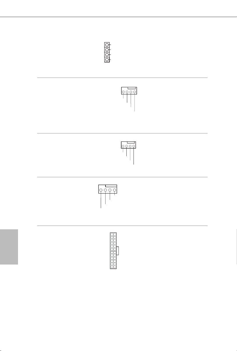
Header altoparlante
4 3 2 1
4 3 2 1
4 3 2 1
chassis
(SPEAKER1 a 4 pin)
(vedere pag. 1, n. 16)
1
SPEAKER
DUMMY
DUMMY
+5V
Collegare l'altoparlante dello
chassis a questo header.
Italiano
Connettori ventola chassis /
pompa dell'acqua
(CHA_FAN1/WP a 4 pin)
(vedere pag. 1, n. 4)
Connettore della ventola
dello chassis
(CHA_FAN2 a 4 pin)
(vedere pag. 1, n. 1)
Connettore ventola CPU
(CPU_FAN1 a 4 pin)
(vedere pag. 1, n. 3)
Connettore di
alimentazione ATX
(ATXPWR1 a 24 pin)
(vedere pag. 1, n. 7)
FAN_SPEED_CONTROL
CHA_FAN_SPEED
FAN_VOLTAGE
FAN_SPEED_CONTROL
CHA_FAN_SPEED
GND
+12V
CPU_F
AN_SPEED
FAN_SPEED_CONTROL
12
24
+12V
Questa scheda madre è dotata
di connettori a 4-pin per ventole
rareddamento ad acqua del
telaio. Se si decide di collegare una
ventola telaio con rareddamento
GND
ad acqua a 3 pin, collegarla al pin
1-3.
Collegare il cavo della ventola
al connettore della ventola e far
corrispondere il lo nero al pin di
terra.
GND
Questa scheda madre è dotata
di un connettore per la ventola
della CPU (Ventola silenziosa)
a 4 pin. Se si decide di collegare
una ventola della CPU a 3 pin,
collegarla al pin 1-3.
Questa scheda madre è dotata di
un connettore di alimentazione
ATX a 24 pin.
58
1
13
Page 63

H610M-ITX/ac
8 5
Connettore di
alimentazione ATX da
12 V
(ATX12V1 a 8 pin)
(vedere pag. 1, n. 2)
Header LED indirizzabile
(ADDR_LED1 a 3 pin)
(vedere pag. 1, n. 5)
4
1
GND
DO_ADDR
VOUT
Questa scheda madre è dotata di
un connettore di alimentazione
1
ATX da 12 V a 8 pin. Per utilizzare
un'alimentazione ATX a 4 pin,
collegarla lungo il pin 1 e il pin 5.
*Attenzione: Assicurarsi che il
cavo di alimentazione collegato
sia per la CPU e non la scheda
graca. Non inserire il cavo di
alimentazione PCIe in questo
connettore.
Questo header serve a collegare
il cavo di estensione del LED
indirizzabile
che consente di
scegliere tra vari eetti luce LED.
Attenzione: Non installare mai
il cavo del LED indirizzabile
secondo un orientamento
errato, altrimento potrebbe
danneggiarsi.
* Fare riferimento a pagina 28
per ulteriori istruzioni su questa
basetta.
Italiano
59
Page 64
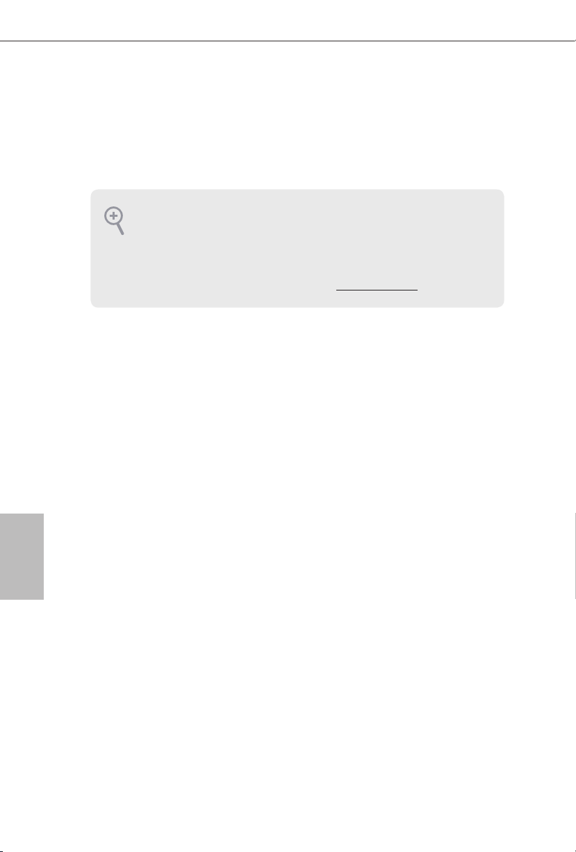
1 Introducción
Gracias por comprar la placa base ASRock H610M-ITX/ac, una placa base able fabricada
según el rigurosísimo control de calidad de ASRock. Ofrece un rendimiento excelente con un
diseño resistente de acuerdo con el compromiso de calidad y resistencia de ASRock.
Ya que las especicaciones de la placa base y el soware de la BIOS podrán ser actualizados, el
contenido que aparece en esta documentación estará sujeto a modicaciones sin previo aviso.
Si esta documentación sufre alguna modicación, la versión actualizada estará disponible en
el sitio web de ASRock sin previo aviso. Si necesita asistencia técnica relacionada con esta placa
base, visite nuestro sitio web para obtener información especíca sobre el modelo que esté
utilizando. Podrá encontrar las últimas tarjetas VGA, así como la lista de compatibilidad de la
CPU, en el sitio web de ASRock. Sitio web de ASRock http://www.asrock.com.
1.1 Contenido del paquete
Placa base ASRock H610M-ITX/ac (factor de forma Mini-ITX)
•
Guía de instalación rápida de ASRock H610M-ITX/ac
•
CD de soporte de ASRock H610M-ITX/ac
•
2 x Cables de datos Serie ATA (SATA) (Opcional)
•
1 x escudo panel E/S
•
2 x Antenas ASRock WiFi 2,4/5 GHz (Opcional)
•
1 x tornillo para socket M.2 (Opcional)
•
Español
60
Page 65

1.2 Especicaciones
Factor de forma Mini-ITX
Plataforma
CPU
Conjunto de
chips
Memoria
•
Diseño de condensador sólido
•
Compatible con la 12a generación de procesadores Intel® CoreTM
•
(LGA1700)
Digi Power design
•
Diseño de 6 fases de alimentación
•
Compatible con la Tecnología Híbrido de Intel®
•
Admite Intel® Turbo Boost Technology 3.0
•
Intel® H610
•
Tecnología de memoria DDR4 de doble canal
•
2 x ranuras DIMM DDR4
•
Admite memoria DDR4 no ECC sin búfer de hasta 3200*
•
* Para obtener más información, consulte la lista de memorias
compatibles en el sitio web de ASRock. (http://www.asrock.com/)
Admite módulos de memoria UDIMM ECC (funcionamiento en
•
modo no ECC)
Capacidad máxima de memoria del sistema: 64GB
•
Admite Perl de memoria extremo de Intel® (XMP) 2.0
•
H610M-ITX/ac
Ranura de
expansión
Grácos
1 ranura PCIe Gen4x16*
•
* Admite unidad de estado sólido de NVMe como disco de arranque
1 x Zócalo M.2 vertical (Clave E), es compatible con los PCIe WiFi
•
módulos WiFi/BT tipo 2230 e Intel® CNVi (WiFi/BT integrado)
* Intel® UHD Graphics Built-in Visuals y las salidas de VGA son
compatibles únicamente con procesadores con GPU integrado.
Arquitectura de grácos Intel® Xe (Generación 12)
•
Salida gráca dual: compatible con puertos HDMI y
•
DisplayPort 1.4 mediante controladores de pantalla independientes
Compatible con HDMI 2.1 TMDS con una resolución máxima de
•
4K x 2K (4096x2160) a 60Hz
Admite DisplayPort 1.4 con DSC (comprimido), resolución
•
máxima hasta 8K (7680x4320) a 60Hz o 5K (5120x3200) a 120Hz
Admite HDCP 2.3 con HDMI 2.1 compatible con TMDS y puertos
•
DisplayPort 1.4
Español
61
Page 66

Español
Audio
LAN
LAN
inalámbrica
E/S en panel
posterior
7.1 Audio CH HD (Códec de audio Realtek ALC897)
•
Admite protección contra sobretensiones
•
Gigabit LAN 10/100/1000 Mb/s
•
Giga PHY Intel® I219V
•
Admite la función Reactivación de LAN
•
Admite protección contra rayos y descargas electrostáticas (ESD)
•
Admite Ethernet 802.3az de eciencia energética
•
Admite UEFI PXE
•
Módulo WiFi 802.11ac
•
Compatible con IEEE 802.11a/b/g/n/ac
•
Compatible con Banda Dual (2,4/5 GHz)
•
Compatible con conexión inalámbrica de alta velocidad hasta 433
•
Mbps
Admite Bluetooth + alta velocidad de clase II
•
2 x Puertos de antena
•
1 x puerto de ratón/teclado PS/2
•
1 x puerto HDMI
•
1 x DisplayPort 1.4
•
2 x Puertos USB 3.2 Gen1 (admite protección contra descargas
•
electrostáticas)
2 x Puertos USB 2.0 (admite protección contra descargas
•
electrostáticas)
1 x Puerto LAN RJ-45 con LED (LED DE ACTIVIDAD/ENLACE
•
y LED DE VELOCIDAD)
Conector de audio HD: Entrada de línea / Altavoz frontal /
•
Micrófono
62
Almacenamiento
4 x Conectores SATA3 de 6,0 Gb/s*
•
* Si M2_1 se ocupa con un dispositivo M.2 de tipo SATA, SATA3_0 se
deshabilitará.
1 x Zócalo Ultra M.2 (M2_1, Clave M), compatible con los modos
•
de tipo 2280 SATA3 6,0 Gb/s y PCIe Gen3x4 (32 Gb/s)**
** Admite el Dispositivo de Administración de Volumen (VMD, según
sus siglas en ingles) de Intel®
** Admite unidad de estado sólido de NVMe como disco de arranque
** Admite el kit U.2 de ASRock
Page 67

Conector
H610M-ITX/ac
1 x Base de conexiones de LED direccionable
•
* Admite una tira de LED de hasta 5 V/3 A (15 W) en total
1 x Conector para ventilador de la CPU (4 contactos)
•
* El conector para ventilador de la CPU admite ventilador de la CPU
con una potencia de ventilador de 1 A (12 W) máxima.
1 x Conector para ventilador del chasis (4 contactos)
•
* El conector para ventilador del chasis admite el ventilador del chasis
con una potencia de ventilador máxima de 1 A (12 W).
1 x Conector (4 contactos) para el ventilador de la bomba de agua/
•
chasis (control de velocidad de ventilador inteligente)
* El ventilador de la bomba de agua/Chasis admite ventilador del
disipador por agua con una potencia de ventilador máxima de 2 A
(24 W).
* CHA_FAN1/WP se pueden detectar automáticamente si se usa el
ventilador de 3 o 4 contactos.
1 x Conector de alimentación ATX de 24 contactos
•
1 x Conector de alimentación de 12V de 8 contactos
•
1 x Conector de audio en el panel frontal
•
1 x Base de conexiones USB 2.0 (admite 2 puertos USB 2.0)
•
(admite protección contra descargas electrostáticas)
1 x Base de conexiones USB 3.2 Gen1 (admite 2 puertos USB 3.2
•
Gen1) (admite protección contra descargas electrostáticas)
Función de la
BIOS
Monitor de
hardware
BIOS legal UEFI AMI compatible con interfaz gráca de usuario
•
multilingüe
Eventos de reactivación compatibles con ACPI 6.0
•
Admite SMBIOS 2.7
•
Varios ajustes de voltaje de núcleo y caché de CPU, GT de CPU,
•
DRAM, VCCIN AUX, +1,05V PROC, +1,8V PROC, +0,82V PCH,
+1,05V PCH
Tacómetro del ventilador: Ventiladores de la bomba de agua/chasis,
•
chasis, CPU
Ventilador silencioso (ajuste automático de la velocidad del
•
ventilador del chasis por temperatura de la CPU): Ventiladores de
la bomba de agua/chasis, chasis, CPU
Control de varias velocidades del ventilador: Ventiladores de la
•
bomba de agua/chasis, chasis, CPU
Supervisión del voltaje: Vcore de CPU, +12 V, +5 V, +3,3 V, +1,05 V
•
PCH
Español
63
Page 68
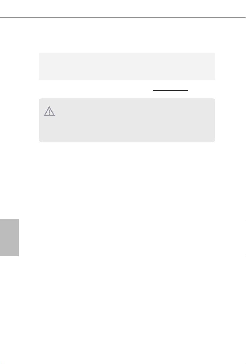
Microso® Windows® 10 64 bits/11 64 bits
SO
Certicaciones
•
FCC y CE
•
Preparado para ErP/EuP (se necesita una fuente de alimentación
•
preparada para ErP/EuP)
* Para obtener información detallada del producto, visite nuestro sitio Web: http://www.asrock.com
Tenga en cuenta que hay un cierto riesgo implícito en las operaciones de overclocking,
incluido el ajuste de la BIOS, aplicando la tecnología de overclocking liberada o utilizando las
herramientas de overclocking de otros fabricantes. El overclocking puede afectar a la estabilidad
del sistema e, incluso, dañar los componentes y dispositivos del sistema. Esta operación se debe
realizar bajo su propia responsabilidad y usted debe asumir los costos. No asumimos ninguna
responsabilidad por los posibles daños causados por el overclocking.
Español
64
Page 69

H610M-ITX/ac
1.3 Instalación de los puentes
La instalación muestra cómo deben instalarse los puentes. Cuando la tapa de puente se
coloca en los contactos, el puente queda “Corto”. Si no coloca la tapa de puente en los
contactos, el puente queda “Abierto”.
Puente de borrado de
CMOS
(CLRMOS1)
(consulte la pág. 1, nº 15)
CLRMOS1 le permite borrar los datos del CMOS. Para borrar y restablecer los parámetros
del sistema a los valores predeterminados de instalación, apague el ordenador y desenchufe
el cable de alimentación de la toma de alimentación. Después de esperar 15 segundos,
utilice una tapa de puente para acortar los contactos en el CLRMOS1 durante 5 segundos.
Sin embargo, no borre el CMOS justo después de que haya actualizado la BIOS. Si necesita
borrar el CMOS cuando acabe de actualizar la BIOS, deberá arrancar el sistema primero y,
a continuación, deberá apagarlo antes de que realice el borrado del CMOS. Tenga en cuenta
que la contraseña, la fecha, la hora y el perl de usuario predeterminado serán eliminados
únicamente si se retira la pila del CMOS. Acuérdese de retirar la tapa de puente después de
borrar el CMOS.
Puente de 2 contactos
Español
65
Page 70

1.4 Conectores y cabezales incorporados
Los cabezales y conectores incorporados NO son puentes. NO coloque tapas de puente sobre
estos cabezales y conectores. Si coloca tapas de puente sobre los cabezales y conectores dañará
de forma permanente la placa base.
Español
Cabezal del panel del
sistema
(PANEL1 de 9 contactos)
(consulte la pág. 1, nº 13)
PWRBTN (Interruptor de alimentación):
Conéctelo al interruptor de alimentación del panel frontal del chasis. Deberá congurar la
forma en la que su sistema se apagará mediante el interruptor de alimentación.
RESET (Interruptor de reseteo):
Conéctelo al interruptor de reseteo del panel frontal del chasis. Pulse el interruptor de reseteo
para resetear el ordenador si éste está bloqueado y no se puede reiniciar de forma normal.
PLED (Indicador LED de la alimentación del sistema):
Conéctelo al indicador de estado de la alimentación del panel frontal del chasis. El indicador
LED permanece encendido cuando el sistema está funcionando. El indicador LED parpadea
cuando el sistema se encuentra en estado de suspensión S1/S3. El indicador LED se apaga
cuando el sistema se encuentra en estado de suspensión S4 o está apagado (S5).
HDLED (Indicador LED de actividad en el disco duro):
Conéctelo al indicador LED de actividad en el disco duro del panel frontal del chasis. El
indicador LED permanece encendido cuando el disco duro está leyendo o escribiendo datos.
El diseño del panel frontal puede ser diferente dependiendo del chasis. Un módulo de panel
frontal consta principalmente de: interruptor de alimentación, interruptor de reseteo, indicador
LED de alimentación, indicador LED de actividad en el disco duro, altavoz, etc. Cuando
conecte su módulo del panel frontal del chasis a este cabezal, asegúrese de que las asignaciones
de los cables y los contactos coinciden correctamente.
Conecte el interruptor de
alimentación, restablezca el
interruptor y el indicador del
estado del sistema del chasis a los
valores de este cabezal, según los
valores asignados a los contactos
como se indica a continuación.
Cerciórese de cuáles son los
contactos positivos y los negativos
antes de conectar los cables.
66
Page 71

H610M-ITX/ac
Conectores Serie ATA3
(SATA3_0:
consulte la pág.1, nº 10)
(SATA3_1:
consulte la pág.1, nº 9)
(SATA3_2:
consulte la pág.1, nº 12)
(SATA3_3:
consulte la pág.1, nº 11)
Cabezal USB 2.0
(USB_3_4 de 9 contactos)
(consulte la pág. 1, nº 14)
Cabezal USB 3.2 Gen1
(USB3_3_4 de
19 contactos)
(consulte la pág. 1, nº 8)
Cabezal de audio del
panel frontal
(HD_AUDIO1 de
9 contactos)
(consulte la pág. 1, nº 17)
IntA_PA_SSRX-
IntA_PA_SSRX+
IntA_PA_SSTX-
IntA_PA_SSTX+
MIC2_L
MIC2_R
OUT2_R
IntA_PA_D-
IntA_PA_D+
J_SENS
OUT2_L
SATA3_1
SATA3_3
Vbus
GND
GND
E
1
VbusVbus
IntA_PB_SSRX-
IntA_PB_SSRX+
GND
IntA_PB_SSTX-
IntA_PB_SSTX+
GND
IntA_PB_D-
IntA_PB_D+
Dummy
1
MIC_RET
OUT_RET
SATA3_0
SATA3_2
GND
PRESENCE#
Estos cuatro conectores SATA3
son compatibles con cables de
datos SATA para dispositivos de
almacenamiento interno con una
velocidad de transferencia de
datos de hasta 6,0 Gb/s.
* Si M2_1 se ocupa con un
dispositivo M.2 de tipo SATA,
SATA3_0 se deshabilitará.
Esta placa base de conexiones
USB2.0 en esta placa base. Cada
base de conexiones USB 2.0
admite dos puertos.
Esta placa base tiene otra base
de conexiones. Esta base de
conexiones USB 3.2 Gen1 admite
dos puertos.
Este cabezal se utiliza para
conectar dispositivos de audio al
panel de audio frontal.
1. El Audio de Alta Denición (HDA, en inglés) es compatible con el método de sensor de
conectores, sin embargo, el cable del panel del chasis deberá ser compatible con HDA para
que pueda funcionar correctamente. Siga las instrucciones que se indican en nuestro manual
y en el manual del chasis para instalar su sistema.
2. Si utiliza un panel de audio AC’97, colóquelo en el cabezal de audio del panel frontal
siguiendo los pasos que se describen a continuación:
A. Conecte Mic_IN (MIC) a MIC2_L.
B. Conecte Audio_R (RIN) a OUT2_R y Audio_L (LIN) a OUT2_L.
C. Conecte Ground (Conexión a tierra) (GND) a Ground (GND).
D. MIC_RET y OUT_RET se utilizan únicamente con el panel de audio HD. No es necesario
que los conecte en el panel de audio AC’97.
E. Para activar el micrófono frontal, vaya a la cha “micrófono frontal” (Front Mic) en el
panel de control de Realtek y ajuste el “Volumen de grabación” (Recording Volume).
Español
67
Page 72
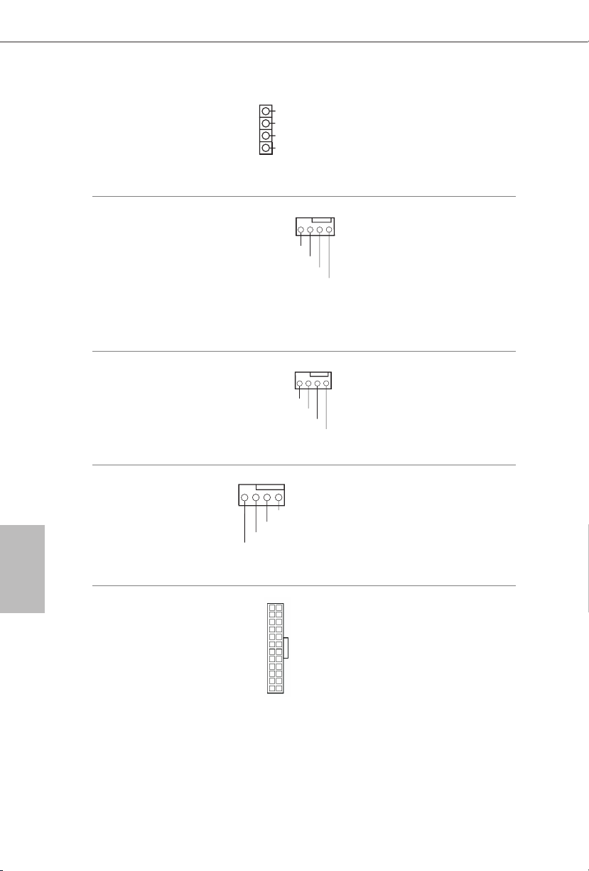
Cabezal de altavoces del
4 3 2 1
4 3 2 1
4 3 2 1
chasis
(SPEAKER1 de
4 contactos)
(consulte la pág. 1, nº 16)
1
SPEAKER
DUMMY
DUMMY
+5V
Conecte el altavoz del chasis a este
cabezal.
Español
Conectores del ventilador
de la bomba de agua/
chasis
(CHA_FAN1/WP de
4 contactos)
(consulte la pág. 1, nº 4)
Conector del ventilador
del chasis
(CHA_FAN2 de
4 contactos)
(consulte la pág. 1, nº 1)
Conector del ventilador de
la CPU
(CPU_FAN1 de
4 contactos)
(consulte la pág. 1, nº 3)
Conector de alimentación
ATX
(ATXPWR1 de
24 contactos)
(consulte la pág. 1, nº 7)
FAN_SPEED_CONTROL
CHA_FAN_SPEED
FAN_VOLTAGE
FAN_SPEED_CONTROL
CHA_FAN_SPEED
GND
+12V
CPU_F
AN_SPEED
FAN_SPEED_CONTROL
12
24
1
13
+12V
Esta placa base proporciona un
conector de ventilador del chasis
de refrigeración por agua de
4 contactos. Si tiene pensando
conectar un ventilador de
GND
disipador por agua del chasis de
3 contactos, conéctelo al contacto
1-3.
Conecte el cable del ventilador
al conector del ventilador y haga
coincidir el cable negro con el pin
de conexión a tierra.
GND
Esta placa base contiene un
conector de ventilador (ventilador
silencioso) de CPU de 4 contactos.
Si tiene pensando conectar un
ventilador de CPU de 3 contactos,
conéctelo al contacto 1-3.
Esta placa base contiene un
conector de alimentación ATX de
24 contactos.
68
Page 73

H610M-ITX/ac
8 5
Conector de alimentación
ATX de 12 V
(ATX12V1 de 8 contactos)
(consulte la pág. 1, nº 2)
Base de conexiones de
LED direccionable
(ADDR_LED1 de
3 contactos)
(consulte la pág. 1, nº 5)
4
1
DO_ADDR
VOUT
GND
Esta placa base contiene un
conector de alimentación ATX de
1
12 V y 8 contactos. Para utilizar
una toma de alimentación ATX
de 4 contactos, conéctela en los
contactos del 1 al 5.
*Advertencia: Asegúrese de
que el cable de alimentación
conectado corresponda a este
CPU y no a la tarjeta gráca. No
conecte el cable de alimentación
PCIe a este conector.
La base de conexiones se usa para
conectar el alargador de LED
direccionable
que permite a los
usuarios elegir entre varios efectos
de iluminación LED.
Precaución: Nunca instale el
cable de LED direccionable con
la orientación incorrecta ya que,
de lo contrario, el cable puede
dañarse.
*Consulte la página 28 para
obtener más instrucciones sobre
esta base de conexiones.
Español
69
Page 74

Русский
1 Введение
Благодарим вас за приобретение надежной системной платы ASRock H610M-ITX/ac,
выпускаемой под постоянным жестким контролем качества компании ASRock. Эта
материнская плата обеспечивает великолепную производительность и отличается
надежной конструкцией в соответствии с требованиями компании ASRock в
отношении качества и долговечности.
По причине обновления характеристик системной платы и программного
обеспечения BIOS содержимое настоящей документации может быть изменено без
предварительного уведомления. При изменении содержимого настоящего документа
его обновленная версия будет доступна на веб-сайте ASRock без предварительного
уведомления. При необходимости технической поддержки, связанной с материнской
платой, посетите веб-сайт и найдите на нем информацию о модели используемой
вами материнской платы. На веб-сайте ASRock также можно найти самый
последний перечень поддерживаемых VGA-карт и ЦП. Веб-сайт ASRock
http://www.asrock.com.
1.1 Комплект поставки
Системная плата ASRock H610M-ITX/ac (форм-фактор Mini-ITX)
•
Краткое руководство по установке платы ASRock H610M-ITX/ac
•
Компакт-диск с ПО для платы ASRock H610M-ITX/ac
•
2 кабеля передачи данных Serial ATA (SATA) (приобретаются отдельно)
•
1 экран панели с портами ввода-вывода
•
2 ASRock WiFi-антенны 2,4/5 ГГц (приобретаются отдельно)
•
1 x Винт для гнезда M.2 (приобретаются отдельно)
•
70
Page 75

1.2 Технические характеристики
Форм-фактор Mini-ITX
Платформа
ЦП
Чипсет
Память
•
Схема на основе твердотельных конденсаторов
•
Поддержка процессоров 12-го поколения Intel® CoreTM
•
(LGA1700)
Digi Power design
•
Система питания 6
•
Поддержка технологии Intel® Hybrid
•
Поддерживается технология Intel® Turbo Boost Max 3.0
•
Intel® H610
•
Двухканальная память DDR4
•
2 x гнезда DDR4 DIMM
•
Поддержка небуферизованной памяти DDR4 без ЕСС до 3200*
•
* Дополнительная информация представлена в Списке
совместимой памяти (Memory Support List) на веб-сайте ASRock.
(http://www.asrock.com/)
Поддержка модулей памяти ECC UDIMM (работа в режиме,
•
отличном от ЕСС)
Максимальный объем ОЗУ: 64 Гб
•
Поддерживается Intel® Extreme Memory Prole (XMP) 2.0
•
H610M-ITX/ac
Слоты
расширения
Графическая
подсистема
1 x PCIe Gen4x16 гнезд*
•
* Поддерживаются в качестве загрузочных SSD-диски типа NVMe
вертикальный слот M.2 (ключ E) для модуля типа 2230 Wi-Fi/
•
BT PCIe Wi-Fi и Intel® CNVi (встроенные Wi-Fi/BT) х1шт.
* Встроенный видеоадаптер Intel® UHD Graphics и выходы VGA
поддерживаются только при использовании ЦП со встроенными
графическими процессорами.
Графическая архитектура Intel® Xe (12поколение)
•
Два графических выхода: поддержка портов HDMI и
•
DisplayPort 1.4 независимыми контроллерами дисплея
Поддержка HDMI 2.1 TMDS совместим с максимальным
•
разрешением до 4K × 2K (4096x2160) при 60 Гц
Поддержка DisplayPort 1.4 с DSC (в сжатом формате), с макс.
•
разрешением до 8К (7680x4320), 60 Гц/ 5K (5120x3200), 120 Гц
Поддержка HDCP 2.3 с разъемами, совместимыми с HDMI 2.1
•
TMDS, и DisplayPort 1.4
Русский
71
Page 76

Русский
Звук
LAN
Беспроводная ЛВС
Тыловые
порты вводавывода
7.1-канальный звук высокой четкости (аудиокодек Realtek
•
ALC897)
Защита от перепадов напряжения в электрической сети
•
Gigabit Ethernet 10/100/1000 Мбит/с
•
Giga PHY Intel® I219V
•
Поддерживается пробуждение по ЛВС
•
Молниезащита и защита от электростатических разрядов
•
Поддерживается Energy Ecient Ethernet 802.3az
•
Поддерживается UEFI PXE
•
Модуль WiFi 802.11ac
•
Поддержка IEEE 802.11a/b/g/n/ac
•
Поддержка двух диапазонов (2,4/5 ГГц)
•
Поддержка высокоскоростного беспроводного подключения
•
до 433 Мбит/с
Поддержка Bluetooth + высокоскоростной класс II
•
2 x антенных порта
•
1 x порт PS/2 для мыши/клавиатуры
•
1 x порт HDMI
•
1 x порт DisplayPort 1.4
•
2 x портов USB 3.2 Gen1 (с защитой от электростатических
•
разрядов)
2 x порта USB 2.0 (с защитой от электростатических разрядов)
•
1 x порт ЛВС RJ-45 с индикаторами (Активность/Соединение
•
и Скорость)
Разъемы HD Audio: линейный вход / фронтальные АС /
•
микрофон
72
Запоминающие
устройства
Разъем SATA3 6,0Гбит/с*x4шт.
•
* Если слот M2_1 занят устройством М.2 типа SATA, интерфейс
SATA3_0 будет отключен.
Гнездо Ultra M.2 (M2_1, Key M), поддержка режимов 2280
•
SATA3 6,0Гбит/с и PCIe Gen3x4 (32Гбит/с)**x1шт.**
** Поддержка технологии Intel® Volume Management Device (VMD)
** Поддерживаются в качестве загрузочных SSD-диски типа
NVMe
** Поддерживается комплект ASRock U.2
Page 77

Разъемы
H610M-ITX/ac
1 колодка адресуемой светодиодной подсветки
•
* Поддерживается светодиодная лента (максимум 5В/3А,
суммарной мощностью до 15Вт).
1 x разъем для вентилятора охлаждения ЦП (4-контактный)
•
* Разъем процессорного вентилятора поддерживает вентилятор с
потребляемым током не более 1А (12Вт).
1 разъем для корпусного вентилятора (4-контактный)
•
* Разъем корпусного вентилятора поддерживает вентилятор с
потребляемым током не более 1А (12Вт).
1 разъем для корпусного вентилятора или водяной помпы
•
(4-контактный) (смарт-регулятор скорости вентилятора)
* Разъем для корпуса корпусного вентилятора или водяной
помпы поддерживает вентилятор с потребляемым током не более
2А (24Вт).
* Для разъемов CHA_FAN1/WP автоматически определяется тип
подключенного вентилятора: 3- или 4-контактный.
1 разъем питания АТХ, 24-контактный
•
1 разъем питания 12 В, 8-контактный
•
1 аудиоразъем для передней панели
•
1 колодка USB 2.0 (2 порта USB 2.0 с защитой от
•
электростатических разрядов)
1 колодка USB 3.2 Gen1 (2 порта USB 3.2 Gen1) (с защитой от
•
электростатических разрядов)
Параметры
BIOS
Контроль
оборудования
AMI UEFI Legal BIOS с поддержкой многоязычного
•
графического интерфейса
Поддержка функций пробуждения по стандарту ACPI 6.0
•
Поддержка SMBIOS 2.7
•
CPU Core/Cache, CPU GT, DRAM, VCCIN AUX, контроль
•
напряжения: +1,05 В PROC, +1,8 В PROC, +0,82 В PCH,
+1,05 В PCH
Тахометр: вентилятор ЦП; корпусной, корпусной вентилятор
•
или помпа водяного охлаждения корпуса
Бесшумная работа (с автоматической регулировкой скорости
•
вращения в зависимости от температуры ЦП): вентилятор
ЦП; корпусной, корпусной вентилятор или помпа водяного
охлаждения корпуса
Русский
73
Page 78

Русский
Регулировка скорости вращения: вентилятор ЦП; корпусной,
•
корпусной вентилятор или помпа водяного охлаждения
корпуса
Контроль напряжений: Vcore ЦП, +12 В, +5 В, +3,3 В, +1,05 В
•
PCH
Microso® Windows® 10 (64-разрядная) / 11 (64-разрядная)
Операцион-
•
ные системы
FCC, CE
Сертификация
•
Совместимость с ErP/EuP (необходим блок питания,
•
соответствующий стандарту ErP/EuP)
* С дополнительной информацией об изделии можно ознакомиться на веб-сайте: http://www.asrock.com
Следует учитывать, что разгон процессора, включая изменение настроек BIOS,
применение технологии Untied Overclocking и использование инструментов разгона
независимых производителей, сопряжен с определенным риском. Разгон процессора
может снизить стабильность системы или даже привести к повреждению ее
компонентов и устройств. Разгон процессора осуществляется пользователем
на собственный риск и за собственный счет. Мы не несем ответственность за
возможный ущерб, вызванный разгоном процессора.
74
Page 79

H610M-ITX/ac
1.3 Установка перемычек
Установка перемычек показана на рисунке. При установке перемычки-колпачка
на контакты перемычка «замкнута». Если перемычка-колпачок на контакты не
установлена, перемычка «разомкнута».
Перемычка сброса
настроек CMOS
(CLRMOS1)
(см. стр. 1, № 15)
CLRMOS1 используется для удаления данных CMOS. Чтобы сбросить и обнулить
параметры системы на настройки по умолчанию, выключите компьютер и извлеките
отключите кабель питания от источника питания. Выждите 15 секунд и накидной
перемычкой замкните контакты разъема CLRMOS1 на 5 секунд. Не сбрасывайте
настройки CMOS сразу после обновления BIOS. При необходимости сбросить
настройки CMOS сразу после обновления BIOS сначала перезагрузите систему, а
затем выключите компьютер перед сбросом настроек CMOS. Учтите, что пароль,
дата, время и профиль пользователя по умолчанию сбрасываются только в том
случае, если извлечь батарею CMOS. После сброса настроек CMOS не забудьте снять
накидную перемычку.
2-контактная
перемычка
Русский
75
Page 80
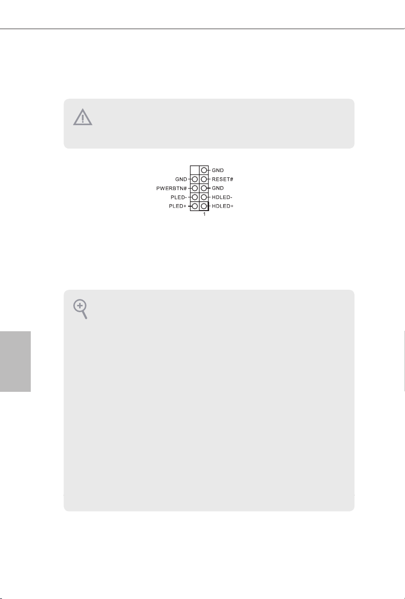
1.4 Колодки и разъемы, расположенные на системной
плате
Расположенные на системной плате колодки и разъемы НЕ являются перемычками.
НЕ устанавливайте на эти колодки и разъемы перемычки-колпачки. Установка
перемычек-колпачков на эти колодки и разъемы может вызвать неустранимое
повреждение системной платы.
Русский
Колодка системной
панели
(9-контактная, PANEL1)
(см. стр.1, № 13)
PWRBTN (кнопка питания):
Подключение кнопки питания, расположенной на передней панели корпуса. Можно
настроить порядок выключения системы с использованием кнопки питания.
RESET (кнопка перезагрузки):
Подключение кнопки перезагрузки системы, расположенной на передней панели
корпуса. Нажмите кнопку перезагрузки, чтобы перезапустить компьютер, если он
завис и нормальный запуск невозможен.
PLED (светодиодный индикатор питания системы):
Подключение индикатора состояния, расположенного на передней панели корпуса.
Светодиодный индикатор горит, когда система работает. Когда система находится
в режиме ожидания S1/S3, светодиод мигает. Когда система находится в режиме
ожидания S4 или выключена (S5), светодиод не горит.
HDLED (светодиодный индикатор работы жесткого диска):
Подключение светодиодного индикатора работы жесткого диска, расположенного на
передней панели. Светодиодный индикатор горит, когда жесткий диск выполняет
считывание или запись данных.
Передняя панель может быть разной на разных корпусах. В основном передняя панель
включает в себя кнопку питания, кнопку перезагрузки, светодиодный индикатор
питания, светодиодный индикатор работы жесткого диска, динамик и т. д. При
подключении передней панели к этой колодке правильно подключайте провода к
контактам.
Подключите расположенные
на корпусе выключатель
питания, кнопку перезагрузки
и индикатор состояния
системы к этой колодке в
соответствии с распределением
контактов, приведенным ниже.
Перед подключением кабелей
определите положительный и
отрицательный контакты.
76
Page 81
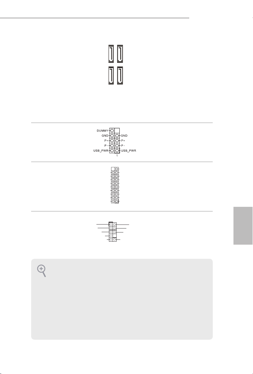
H610M-ITX/ac
Разъемы Serial ATA3
(SATA3_0:
см. стр. 1, № 10)
(SATA3_1:
см. стр. 1, № 9)
(SATA3_2:
см. стр. 1, № 12)
(SATA3_3:
см. стр. 1, № 11)
Колодка USB 2.0
(9-контактная, USB_3_4)
(см. стр. 1, № 14)
Колодки USB 3.2 Gen1
(19-контактная,
USB3_3_4)
(см. стр. 1, № 8)
Аудиоколодка передней
панели
(9-контактов,
HD_AUDIO1)
(см. стр. 1, № 17)
MIC2_L
MIC2_R
OUT2_R
SATA3_1
SATA3_3
Vbus
IntA_PA_SSRX-
IntA_PA_SSRX+
IntA_PA_SSTX-
IntA_PA_SSTX+
IntA_PA_D-
IntA_PA_D+
J_SENS
E
OUT2_L
Эти четыре разъема
SATA3 предназначены для
SATA3_0
подключения кабелей SATA
внутренних запоминающих
устройств для передачи данных
SATA3_2
со скоростью до 6,0 Гбит/с.
* Если слот M2_1 занят
устройством М.2 типа SATA,
интерфейс SATA3_0 будет
отключен.
На системной плате
предусмотрена одна колодка
USB2.0. Эта колодка USB 2.0
может поддерживать два порта.
VbusVbus
IntA_PB_SSRX-
IntA_PB_SSRX+
GND
IntA_PB_SSTX-
GND
IntA_PB_SSTX+
GND
IntA_PB_D-
GND
IntA_PB_D+
Dummy
1
1
MIC_RET
OUT_RET
На материнской плате имеется
одна колодка. Эта колодка USB
3.2 Gen1 поддерживает два
порта.
Эта колодка предназначена для
GND
подключения аудиоустройств к
PRESENCE#
передней аудиопанели.
Русский
1. Аудиосистема высокого разрешения поддерживает функцию распознавания разъема,
но для е правильной работы необходимо, чтобы провод панели корпуса поддерживал
передачу сигналов HDA. Инструкции по установке системы см. в этом руководстве
и руководстве на корпус.
2. При использовании аудиопанели AC’97 подключите ее к аудиоколодке передней
панели, как указано далее:
A. Подключите Mic_IN (MIC) к MIC2_L.
B. Подключите Audio_R (RIN) к OUT2_R, Audio_L (LIN) к OUT2_L.
C. Подключите провод заземления (GND) к контакту заземления (GND).
D. Контакты MIC_RET и OUT_RET используются только для аудиопанели высокого
разрешения. При использовании аудиопанели AC’97 их подключать не нужно.
E. Чтобы активировать передний микрофон, перейдите на вкладку FrontMic панели
управления Realtek и отрегулируйте параметр Recording Volume (Громкость записи).
77
Page 82

Колодка динамика
4 3 2 1
4 3 2 1
4 3 2 1
корпуса
(4-контакта, SPEAKER1)
(см. стр.1, № 16)
1
SPEAKER
DUMMY
DUMMY
+5V
Предназначена для
подключения динамика
корпуса.
Русский
Разъемы для
вентилятора или помпы
водяного охлаждения
корпуса
(4-контактный CHA_
FAN1/WP)
(см. стр.1, № 4)
Разъем вентилятора
корпуса
(4 контактов, CHA_
FAN2)
(см. стр.1, № 1)
Разъем вентилятора
охлаждения процессора
(4-контакта, CPU_FAN1)
(см. стр.1, № 3)
FAN_SPEED_CONTROL
CHA_FAN_SPEED
FAN_VOLTAGE
FAN_SPEED_CONTROL
CHA_FAN_SPEED
GND
+12V
CPU_F
AN_SPEED
FAN_SPEED_CONTROL
+12V
Данная материнская плата
оснащена 4-контактным
разъемом для системы
водяного охлаждения корпуса.
3-контактную систему водяного
GND
охлаждения корпуса следует
подключать к контактам 1–3.
Предназначен для подключения
кабеля разъема вентилятора и
подключения черного провода
к заземлению.
GND
Эта материнская плата
снабжена 4-контактным
разъемом для малошумящего
вентилятора ЦП. Если вы
собираетесь подключить
3-контактный вентилятор
охлаждения процессора,
подключайте его к контактам
1-3.
78
Разъем питания АТХ
(24-контакта,
ATXPWR1)
(см. стр. 1, № 7)
12
24
Эта материнская плата
оснащена 24-контактным
разъемом питания АТХ.
1
13
Page 83
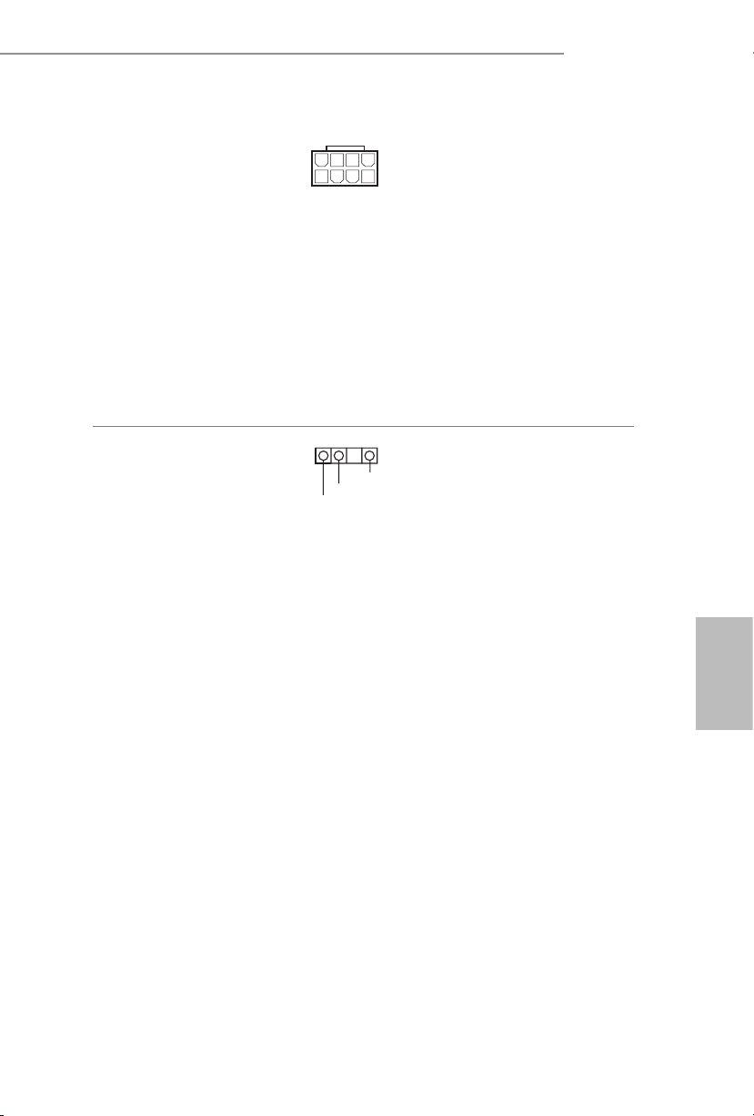
H610M-ITX/ac
8 5
Разъем питания АТХ 12 В
(8-контактов, ATX12V1)
(см. стр. 1, № 2)
Колодка адресуемой
светодиодной подсветки
(3-контакта, ADDR_LED1)
(см. стр. 1, № 5)
4
1
GND
DO_ADDR
VOUT
Эта материнская плата
снабжена 8-контактным
разъемом питания АТХ 12 В.
1
Чтобы использовать
4-контактный разъем питания
ATX, подключите его вдоль
контакта 1 и контакта 5.
*Внимание! Убедитесь,
что подключенный кабель
питания предназначен для
ЦП, а не для видеокарты. Не
подключайте кабель питания
PCIe к этому разъему.
Эта колодка служит для
подключения удлинительного
кабеля
адресуемой
светодиодной подсветки,
которая позволяет реализовать
различные световые эффекты.
Внимание! Категорически
запрещается подключать
кабель адресуемой
светодиодной подсветки с
нарушением полярности, так
как это может привести к его
повреждению.
* Дополнительные сведения об
использовании этой колодки
см. на стр.28.
Русский
79
Page 84
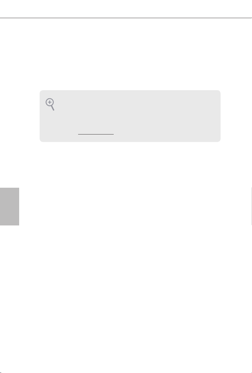
Português
1 Introdução
Obrigado por adquirir a placa mãe ASRock H610M-ITX/ac, uma conável placa mãe
ASRock produzida sob rigoroso controle de qualidade consistente. Esta placa principal
oferece um excelente desempenho com um design robusto em conformidade com o
compromisso da ASRock em fabricar produtos de qualidade e resistentes.
Como as especicações da placa-mãe e do soware do BIOS podem ser atualizadas, o conteúdo
desta documentação estará sujeito a alterações sem aviso prévio. Caso ocorram modicações
a esta documentação, a versão atualizada estará disponível no site da ASRock sem aviso
prévio. Se precisar de assistência técnica relacionada a esta placa principal, visite o nosso site
para obter informações especícas sobre o modelo que estiver utilizando. Você também poderá
encontrar a lista de placas VGA e CPU mais recentes suportadas no site da ASRock. Site da
ASRock http://www.asrock.com.
1.1 Conteúdo da embalagem
Placa Mãe ASRock H610M-ITX/ac (Fator de Forma Mini-ITX)
•
Guia de Instalação Rápida da ASRock H610M-ITX/ac
•
CD de Suporte da ASRock H610M-ITX/ac
•
2 x Cabos de dados Serial ATA (SATA) (Opcional)
•
1 x Painel de E/S
•
2 x Antenas de 2,4/5 GHz da ASRock WiFi (Opcional)
•
1 x Parafuso para Soquete M.2 (Opcional)
•
80
Page 85

1.2 Especicações
Formato Mini-ITX
Plataforma
CPU
Chipset
Memória
•
Design de condensador sólido
•
Suportas Processadores 12th Gen Intel® CoreTM (LGA1700)
•
Digi Power design
•
Design com 6 fases de alimentação
•
Suporta Tecnologia Híbrida Intel®
•
Suporta Tecnologia Intel® Turbo Boost Max 3.0
•
Intel® H610
•
Tecnologia de memória DDR4 de dois canais
•
2 x Slots DIMM DDR4
•
Suporta DDR4 não-ECC, uma memória sem buer até 3200*
•
* Por favor, consulte a Lista de Suporte de Memória no site da ASRock
para obter mais informação. (http://www.asrock.com/)
Suporta módulos de memória ECC UDIMM (opera em modo não-
•
ECC)
Capacidade máxima da memória do sistema: 64GB
•
Suporta Extreme Memory Prole (XMP) 2.0 da Intel®
•
H610M-ITX/ac
Slot de
expansão
Grácos
1 x Slot PCIe Gen4x16*
•
* Suporta NVMe SSD nos discos de inicialização
1 Soquete M.2 Vertical (Chave E), suporta módulo 2230 WiFi/BT
•
PCIe WiFi e Intel® CNVi (WiFi/BT Integrado)
* Os grácos incorporados Intel® UHD e as saídas VGA só podem ser
suportados com processadores com GPU integrada.
Arquitetura Gráca Intel® Xe (Gen 12)
•
Saída gráca dupla: Suporta portas HDMI e DisplayPort 1.4 por
•
controladores de vídeo independentes
Suporta HDMI 2.1 TMDS Compatível com resolução máx. até
•
4K x 2K (4096x2160) @ 60Hz
Obsługa DisplayPort 1.4 z DSC (skompresowany) maks.
•
rozdzielczość do 8K (7680x4320) przy 60Hz / 5K (5120x3200) przy
120Hz
Português
81
Page 86

Áudio
LAN
LAN sem os
Obsługa HDCP 2.3 przy zgodności z HDMI 2.1 TMDS i porty
•
DisplayPort 1.4
Áudio 7.1 CH HD com proteção de conteúdo (Codec de áudio
•
Realtek ALC897)
Suporta Proteção de Sobretensão
•
LAN Gigabit a 10/100/1000 Mb/s
•
Giga PHY Intel® I219V
•
Suporta Wake-On-LAN
•
Oferece Suporte à Proteção de Relâmpago/ESD
•
Suporta Energy Ecient Ethernet 802.3az
•
Suporta UEFI PXE
•
Módulo 802.11ac WiFi
•
Suporta IEEE 802.11a/b/g/n/ac
•
Suporta banda dupla (2,4/5 GHz)
•
Suporta conexão sem o de alta velocidade até 433Mbps
•
Suporta Bluetooth + Alta velocidade classe II
•
Português
82
E/S do painel
posterior
Armazenamento
2 x Portas de Antena
•
1 x Porta PS/2 para mouse/teclado
•
1 x Porta HDMI
•
1 x DisplayPort 1.4
•
2 x Portas USB 3.2 Gen1 (Suporta Proteção ESD)
•
2 x Portas USB 2.0 (Suporta Proteção ESD)
•
1 x Porta LAN RJ-45 com LED (LED ACT/LINK e LED DE
•
VELOCIDADE)
Fichas de áudio HD: Entrada de Linha / Autofalante Frontal /
•
Microfone
4 x Conectores SATA3 6,0 Gb/s*
•
* Se M2_1 é ocupado por um dispositivo tipo M.2 SATA, SATA3_0
será desativado.
1 x Soquete Ultra M.2 (M2_1, Chave M), suporta modos tipo 2280
•
SATA3 6,0 Gb/s & PCIe Gen3x4 (32 Gb/s)**
** Suporta o Dispositivo de Gerenciamento de Volume Intel® (VMD)
** Suporta NVMe SSD como discos de inicialização
** Suporta Kit ASRock U.2
Page 87

Conector
H610M-ITX/ac
1 x Plataforma de LED Ajustável
•
* Suporta no total até 5V/3A, Tira de LED de 15W
1 x Conector da ventoinha da CPU (4 pinos)
•
* O Conector do Ventilador de CPU suporta o ventilador de CPU de
alimentação máxima 1A do ventilador (12W).
1 x Conector da ventoinha do Gabinete (4 pinos)
•
* O Conector do Ventilador do Chassi suporta o ventilador do chassi
de potência do ventilador máxima de 1A (12W).
1 x Conector do ventilador do chassi/Ventilador da Bomba de Água
•
(4 pinos) (Controle de Velocidade de Ventoinha Inteligente)
* O Ventilador de Chassi/Ventilador da Bomba de Água suporta o
ventilador de refrigerador a água de 2A máximo (24W) potência do
ventilador.
* CHA_FAN1/WP podem detectar automaticamente se ventoinha de
3 pinos ou 4 pinos está em uso.
1 x Conector alimentação ATX 24-pinos
•
1 x Conector de energia 8-pinos 12V
•
1 x Conector de áudio do painel frontal
•
1 x Plataforma USB 2.0 (Suporta 2 portas USB 2.0) (Suporta
•
Proteção ESD)
1 x Plataforma USB 3.2 Gen1 (Suporta 2 portas USB 3.2 Gen1)
•
(Suporta Proteção ESD)
Funções da
BIOS
Monitor de
hardware
AMI Legal UEFI BIOS com suporte multilingue GUI
•
ACPI 6.0 compatível com eventos de despertar
•
Suporte SMBIOS 2.7
•
CPU Core/Cache, CPU GT, DRAM, VCCIN AUX, +1,05V PROC,
•
+1,8V PROC, +0,82V PCH, +1,05V PCH de Tensão de Multi-ajuste
Tacômetro da ventoinha: Ventilador da CPU, Chassis, Chassis/
•
Bomba de Água
Ventoinha Silenciosa (Auto ajusta velocidade da ventoinha do
•
chassi pela temperatura da CPU): Ventilador da CPU, Chassis,
Chassis/Bomba de Água
Controle multi-velocidade da ventoinha: Ventilador da CPU,
•
Chassis, Chassis/Bomba de Água
Monitoramento da tensão: CPU Vcore, +12V, +5V, +3,3V, +1,05V
•
PCH
Português
83
Page 88

Português
Microso® Windows® 10 64-bit / 11 64-bit
SO
Certicações
•
FCC, CE
•
Preparada para ErP/EuP (é necessária uma fonte de alimentação
•
preparada para ErP/EuP)
* Para obter informações detalhadas sobre o produto, por favor, visite o nosso site: http://www.asrock.com
Por favor, observe que existe um certo risco envolvendo overclocking, incluindo o ajuste
das denições na BIOS, a aplicação de tecnologia Untied Overclocking ou a utilização de
ferramentas de overclocking de terceiros. O overclocking poderá afetar a estabilidade do sistema
ou mesmo causar danos nos componentes e dispositivos do seu sistema. Ele deve ser realizado
por sua conta e risco. Não nos responsabilizamos por possíveis danos causados pelo overclocking.
84
Page 89
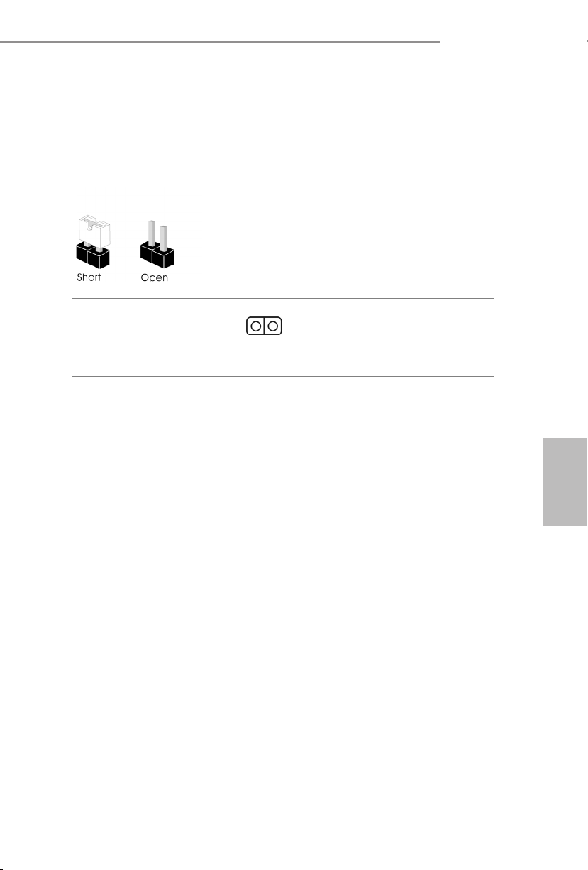
H610M-ITX/ac
1.3 Conguração dos jumpers
A imagem abaixo mostra como os jumpers são congurados. Quando a tampa do jumper é
colocada nos pinos, o jumper é "Curto". Se não for colocada uma tampa de jumper nos pinos,
o jumper é "Aberto".
Apagar o Jumper CMOS
(CLRMOS1)
(ver p.1, N.º 15)
CLRMOS1 permite que você limpe os dados do CMOS. Para apagar e reinicializar os
parâmetros do sistema nos valores predenidos, desligue o computador e desplugue a
tomada da alimentação. Depois de aguardar 15 segundos, use uma capa de jumper para
fazer curto dos pinos no CLRMOS1 por 5 segundos. No entanto, não apague o CMOS logo
após ter realizado a atualização da BIOS. Se você precisar apagar o CMOS logo após ter
terminado uma atualização da BIOS, deverá primeiro iniciar o sistema e voltar a encerrálo antes de apagar o CMOS. Por favor, observe que a senha, data, hora e perl padrão do
usuário serão apagados só se a bateria CMOS for removida. Por favor, não se esqueça de
retirar a tampa do jumper depois de apagar o CMOS.
Jumper de 2 pinos
Português
85
Page 90

1.4 Suportes e conectores onboard
Os conectores e suportes onboard NÃO são jumpers. NÃO coloque tampas de jumpers sobre
estes terminais e conectores. Colocar tampas de jumpers sobre os terminais e conectores irá
causar danos permanentes à placa-mãe.
Português
Suporte do painel de
sistema
(PAINEL1 de 9 pinos)
(ver p.1, N.º 13)
PWRBTN (Botão de alimentação):
Conecte o botão de alimentação no painel frontal do chassi. Você pode congurar a forma para
desligar o seu sistema através do botão de alimentação.
RESET (Botão de reinicialização):
Conecte o botão de reinicialização no painel frontal do chassi. Pressione o botão de
reinicialização para reiniciar o computador, se ele congela e falha ao realizar um reinício
normal.
PLED (LED de alimentação do sistema):
Conecte o indicador do estado da alimentação no painel frontal do chassi. O LED cará aceso
quando o sistema estiver em funcionamento. O LED cará piscando quando o sistema estiver
nos estados de suspensão S1/S3. O LED cará desligado quando o sistema estiver no estado de
suspensão S4 ou desligado (S5).
HDLED (LED de atividade do disco rígido):
Conecte o LED de atividade do disco rígido no painel frontal do chassi. O LED cará aceso
quando o disco rígido estiver lendo ou registrando dados.
O design do painel frontal poderá variar dependendo do chassi. Um módulo de painel frontal
consiste principalmente em um botão de alimentação, um botão de reinicialização, um LED
de alimentação, um LED de atividade do disco rígido, um alto-falante, etc. Ao conectar
seu módulo de painel frontal do chassi a este conector, certique-se de que os os e os pinos
correspondem de forma correta.
Ligue o botão de alimentação,
o botão de reinicialização e o
indicador do estado do sistema
no chassi deste suporte, de acordo
com a descrição abaixo. Observe
os pinos positivos e negativos
antes de conectar os cabos.
86
Page 91

H610M-ITX/ac
Conectores série ATA3
(SATA3_0:
ver p.1, N.º 10)
(SATA3_1:
ver p.1, N.º 9)
(SATA3_2:
ver p.1, N.º 12)
(SATA3_3:
ver p.1, N.º 11)
Suporte USB 2.0
(USB_3_4 de 9 pinos)
(ver p.1, N.º 14)
Plataforma USB 3.2 Gen1
(USB3_3_4 de 19 pinos)
(ver p.1, N.º 8)
Suporte de áudio do
painel frontal
(HD_AUDIO1 de 9 pinos)
(ver p.1, N.º 17)
IntA_PA_SSRX+
IntA_PA_SSTX+
MIC2_L
MIC2_R
OUT2_R
SATA3_1
SATA3_3
IntA_PA_SSRX-
IntA_PA_SSTX-
IntA_PA_D-
IntA_PA_D+
J_SENS
E
OUT2_L
Vbus
GND
GND
1
VbusVbus
IntA_PB_SSRX-
IntA_PB_SSRX+
GND
IntA_PB_SSTX-
IntA_PB_SSTX+
GND
IntA_PB_D-
IntA_PB_D+
Dummy
1
OUT_RET
SATA3_0
SATA3_2
GND
PRESENCE#
MIC_RET
Estes quatro conectores SATA3
suportam cabos de dados
SATA para dispositivos de
armazenamento interno com
uma taxa de transferência de
dados de até 6,0 Gb/s.
* Se M2_1 é ocupado por um
dispositivo tipo M.2 SATA,
SATA3_0 será desativado.
Há um cabeçote USB2.0 nesta
placa-mãe. Cada suporte USB 2.0
pode ter duas portas.
Há um cabeçote nesta placa-mãe.
Este suporte USB 3.2 Gen1 pode
suportar duas portas.
Este suporte destina-se à conexão
dos dispositivos de áudio no
painel de áudio frontal.
Português
1. O Áudio de alta denição suporta Sensor de Adaptador, mas o o do painel no chassi deverá
suportar HDA para funcionar corretamente. Por favor, siga as instruções no nosso manual e
no manual do chassi para instalar o seu sistema.
2. Se utilizar um painel de áudio AC’97, instale-o no terminal de áudio do painel frontal de
acordo com os passos abaixo:
A. Ligue Mic_IN (MIC) a MIC2_L.
B. Conecte o Audio_R (RIN) a OUT2_R e Audio_L (LIN) a OUT2_L.
C. Conecte a ligação Terra (GND) à Terra (GND).
D. MIC_RET e OUT_RET destinam-se apenas ao painel de áudio HD. Você não precisa
ligá-los ao painel de áudio AC’97.
E. Para ativar o microfone frontal, vá à guia “Microfone Frontal” no painel de controle
Realtek e ajuste o “Volume de gravação”.
87
Page 92

Suporte do alto-falante do
4 3 2 1
4 3 2 1
4 3 2 1
chassi
(SPEAKER1 de 4 pinos)
(ver p.1, N.º 16)
1
SPEAKER
DUMMY
DUMMY
+5V
Por favor, conecte o alto-falante do
chassi a este suporte.
Português
Chassis / Conectores da
ventoinha de bomba de
água
(CHA_FAN1/WP de
4 pinos)
(ver p.1, N.º 4)
Conector do ventilador do
chassi
(CHA_FAN2 de 4 pinos)
(ver p.1, N.º 1)
Conector da Ventoinha da
CPU
(CPU_FAN1 de 4 pinos)
(ver p.1, N.º 3)
Conector de alimentação
ATX
(ATXPWR1 de 24 pinos)
(ver p.1, N.º 7)
FAN_SPEED_CONTROL
CHA_FAN_SPEED
FAN_VOLTAGE
FAN_SPEED_CONTROL
CHA_FAN_SPEED
GND
+12V
CPU_F
AN_SPEED
FAN_SPEED_CONTROL
12
24
+12V
Esta placa mãe fornece conectores
de ventilador do chassis de
refrigeração a água de 4 pinos.
Se você pretende conectar um
ventilador de refrigeração a água
GND
de chassis de 3 pinos, por favor,
conecte-o ao Pino 1-3.
Ligue o cabo do ventilador
aos conectores do ventilador e
corresponda o cabo preto com o
pino de ligação à terra.
GND
Esta placa mãe inclui um conector
de ventilador da CPU (Ventilador
silencioso) de 4 pinos. Se você
pretende conectar um ventilador
da CPU de 3 pinos, por favor,
conecte-o ao Pino 1-3.
Esta placa-mãe inclui um conector
de alimentação ATX de 24 pinos.
88
1
13
Page 93

H610M-ITX/ac
8 5
Conector de alimentação
de 12V ATX
(ATX12V1 de 8 pinos)
(ver p.1, N.º 2)
Plataforma de LED
Ajustável
(ADDR_LED1 de 3 pinos)
(ver p.1, N.º 5)
4
1
GND
DO_ADDR
VOUT
Esta placa-mãe inclui um conector
de alimentação de 12V ATX de
1
8 pinos. Para utilizar uma fonte
de alimentação ATX de 4 pinos,
introduza-a no Pino 1 e Pino 5.
*Aviso: Certique-se que o cabo
de força conectado é para o CPU
e não para a placa gráca. Não
ligue o cabo de força PCIe a este
conector.
Esta plataforma é usada para
conectar caboi de extensão
Ajustável
de LED que permite
aos usuários escolher entre vários
efeitos de iluminação de LED.
Atenção: Nunca instale o cabo
de LED Ajustável na orientação
errada, caso contrário o cabo
pode ser danicado.
*Consulte a página 28 para obter
mais informações sobre esta
plataforma.
Português
89
Page 94
1 Wprowadzenie
Dziękujemy za zakupienie płyty głównej ASRock H610M-ITX/ac, niezawodnej płyty głównej
produkowanej z konsekwentnie wykonywaną przez rmę ASRock, rygorystyczną kontrolą
jakości. Płyta ta zapewnia doskonałą jakość działania i solidną konstrukcję, spełniającą
zobowiązanie rmy ASRock do dostarczania produktów o wysokiej jakości i wytrzymałości.
Ponieważ specykacje płyty głównej i oprogramowanie BIOS mogą zostać zaktualizowane,
zawartość tej dokumentacji może zostać zmieniona bez powiadomienia. W przypadku
jakichkolwiek modykacji tej dokumentacji, zaktualizowana wersja będzie dostępna na stronie
internetowej ASRock, bez dalszego powiadomienia. Jeśli wymagana jest pomoc techniczna
w odniesieniu do tej płyty głównej, należy odwiedzić stronę internetową w celu uzyskania
specycznych informacji o używanym modelu. Na stronie internetowej ASRock, można także
pobrać listę najnowszych kart VGA i obsługiwanych CPU. Strona internetowa ASRock
http://www.asrock.com.
1.1 Zawartość opakowania
Płyta główna ASRock H610M-ITX/ac (Współczynnik kształtu Mini-ITX)
•
Polski
Skrócona instrukcja instalacji ASRock H610M-ITX/ac
•
Pomocnicza płyta CD ASRock H610M-ITX/ac
•
2 x kable danych Serial ATA (SATA) (Opcjonalna)
•
1 x osłona panelu Wejścia/Wyjścia
•
2 x anteny ASRock WiFi 2,4/5 GHz (Opcjonalna)
•
1 x śruba do gniazda M.2 (Opcjonalna)
•
90
Page 95

1.2 Specykacje
Platforma
•
•
H610M-ITX/ac
Współczynnik kształtu Mini-ITX
Konstrukcja kondensatorami stałymi
CPU
Chipset
Pamięć
Gniazdo
rozszerzenia
Graka
Obsługa 12
•
Digi Power design
•
Sekcja zasilania 6 Power Phase Design
•
Obsługa technologii Intel® Hybrid
•
Obsługa technologii Intel® Turbo Boost Max 3.0
•
Intel® H610
•
Technologia pamięci Dual Channel DDR4
•
2 x gniazda DDR4 DIMM
•
Obsługa niebuforowanej pamięci DDR4 non-ECC, do 3200*
•
* Sprawdź listę obsługiwanej pamięci na stronie internetowej ASRock
w celu uzyskania dalszych informacji. (http://www.asrock.com/)
Obsługa modułów pamięci ECC UDIMM (działanie w trybie non-
•
ECC)
Maks. wielkość pamięci systemowej: 64GB
•
Obsługa Intel® Extreme Memory Prole (XMP) 2.0
•
1 x gniazda PCIe Gen4x16*
•
* Obsługa SSD NVMe, jako dysków rozruchowych
1 x pionowe gniazdo M.2 (Key E), z obsługą modułu WiFi/BT PCIe
•
typu 2230 i Intel® CNVi (Zintegrowany WiFi/BT)
* Wbudowana graka Intel® UHD i wyjścia VGA są obsługiwane
wyłącznie z procesorami, które mają zintegrowane GPU.
Architektura graki Intel® Xe (Generacja 12)
•
Podwójne wyjście graczne: Obsługa HDMI i DisplayPort 1.4 przez
•
niezależne sterowniki graczne
Obsługa HDMI 2.1 TMDS zgodności z maks. rozdzielczością do
•
4K x 2K (4096x2160) przy 60Hz
Obsługa DisplayPort 1.4 z DSC (skompresowany) maks.
•
rozdzielczość do 8K (7680x4320) przy 60Hz / 5K (5120x3200) przy
120Hz
-tej
generacji procesorów Intel® CoreTM (LGA1700)
Polski
91
Page 96
Obsługa HDCP 2.3 przy zgodności z HDMI 2.1 TMDS i porty
•
DisplayPort 1.4
Dźwięk HD 7.1 CH (kodek audio Realtek ALC897)
Audio
LAN
Bezprzewodowa sieć LAN
Polski
Tylny panel
Wejścia/
Wyjścia
•
Obsługa zabezpieczenia przed przepięciami
•
Gigabit LAN 10/100/1000 Mb/s
•
Giga PHY Intel® I219V
•
Obsługa Wake-On-LAN
•
Obsługa zabezpieczenia przed wyładowaniami atmosferycznymi/
•
ESD
Obsługa Energy Ecient Ethernet 802.3az
•
Obsługa UEFI PXE
•
Moduł WiFi 802.11ac
•
Obsługa IEEE 802.11a/b/g/n/ac
•
Obsługa dwóch pasm (2,4/5 GHz)
•
Obsługa wysokiej szybkości połączeń bezprzewodowych do
•
433 Mbps
Obsługa Bluetooth + Wysokiej szybkości klasa II
•
2 x porty anteny
•
1 x port myszy/klawiatury PS/2
•
1 x port HDMI
•
1 x DisplayPort 1.4
•
2 x porty USB 3.2 Gen1 (Obsługa zabezpieczenia ESD)
•
2 x porty USB 2.0 (Obsługa zabezpieczenia ESD)
•
1 x port LAN RJ-45 z LED (LED ACT/LINK i LED SPEED)
•
Gniazda audio HD: Wejście liniowe / Głośnik przedni / Mikrofon
•
92
Przechowywanie
4 x złącza SATA3 6,0 Gb/s*
•
* Jeśli gniazdo M2_1 jest zajęte przez urządzenie M.2 typu SATA,
zostanie wyłączone SATA3_0.
1 x Ultra M.2 Socket (M2_1, Key M), z obsługą typu 2280 SATA3
•
6,0 Gb/s i trybów PCIe Gen3x4 (32 Gb/s)**
** Obsługa Intel® Volume Management Device (VMD)
** Obsługa SSD NVMe, jako dysków rozruchowych
** Obsługa ASRock U.2 Kit
Page 97

Złącze
H610M-ITX/ac
1 x Adresowalne złącze główkowe LED
•
* Obsługa łącznie do 5V/3A, pasek LED 15W
1 x złącze wentylatora CPU (4-pinowe)
•
* Złącze wentylatora CPU obsługuje wentylator CPU maksymalnym
prądem zasilania wentylatora 1A (12W).
1 x złącze wentylatora obudowy (4-pinowe)
•
* Złącze wentylatora obudowy obsługuje wentylator obudowy
maksymalnym prądem zasilania wentylatora 1 A (12 W).
1 x złącza wentylatora obudowy/pompy wodnej (4-pinowe)
•
(Inteligentne sterowanie prędkością obrotową wentylatora)
* Złącze wentylatora obudowy/pompy wodnej obsługuje wentylator
układu chłodzenia maksymalnym prądem zasilania wentylatora 2 A
(24 W).
* CHA_FAN1/WP może automatycznie wykrywać, jeśli używany jest
wentylator 3-pinowy lub 4-pinowy.
1 x 24 pinowe złącze zasilania ATX
•
1 x 8 pinowe złącze zasilania 12 V
•
1 x złącze audio na panelu przednim
•
1 x złącza główkowe USB 2.0 (obsługuje 2 porty USB 2.0)
•
(Obsługa zabezpieczenia ESD)
1 x porty główkowe USB 3.2 Gen1 (obsługa 2 portów USB 3.2
•
Gen1) (obsługa zabezpieczenia ESD)
Polski
Funkcja BIOS
Monitor
sprzętu
Obsługa starszych wersji BIOS AMI UEFI z wielojęzycznym GUI
•
Zgodność zdarzeń wybudzania z ACPI 6.0
•
Obsługa SMBIOS 2.7
•
Wiele regulacji napięcia CPU Core/Cache, CPU GT, DRAM,
•
VCCIN AUX, +1,05V PROC, +1,8V PROC, +0,82V PCH,
+1,05V PCH
Obrotomierz wentylatora: CPU, obudowa, wentylatory obudowy/
•
pompy wodnej
Cichy wentylator (Automatyczna regulacja prędkości obrotowej
•
wentylatora obudowy przez temperaturę CPU): CPU, obudowa,
wentylatory obudowy/pompy wodnej
Kontrola wielu prędkości obrotowych wentylatora: CPU, obudowa,
•
wentylatory obudowy/pompy wodnej
Monitorowanie napięcia: Napięcie rdzenia CPU Vcore +12 V, +5 V,
•
+3,3 V, +1,05 V PCH
93
Page 98
Microso® Windows® 10 64-bitowy / 11 64-bitowy
System
•
operacyjny
FCC, CE
Certykaty
•
Gotowość do obsługi ErP/EuP (Wymagane zasilanie z gotowością
•
obsługi ErP/EuP)
* Dla uzyskania szczegółowej informacji o produkcie, należy odwiedzić naszą stronę internetową: http://www.asrock.com
Należy pamiętać, że przetaktowywanie jest związane z pewnym ryzykiem, włącznie z regulacją
ustawień w BIOS, zastosowaniem Untied Overclocking Technology lub używaniem narzędzi
przetaktowywania innych rm. Przetaktowywanie może wpływać na stabilność systemu
lub nawet powodować uszkodzenie komponentów i urządzeń systemu. Powinno to zostać
zrobione na własne ryzyko i koszt. Nie odpowiadamy za możliwe uszkodzenia spowodowane
przetaktowywaniem.
Polski
94
Page 99
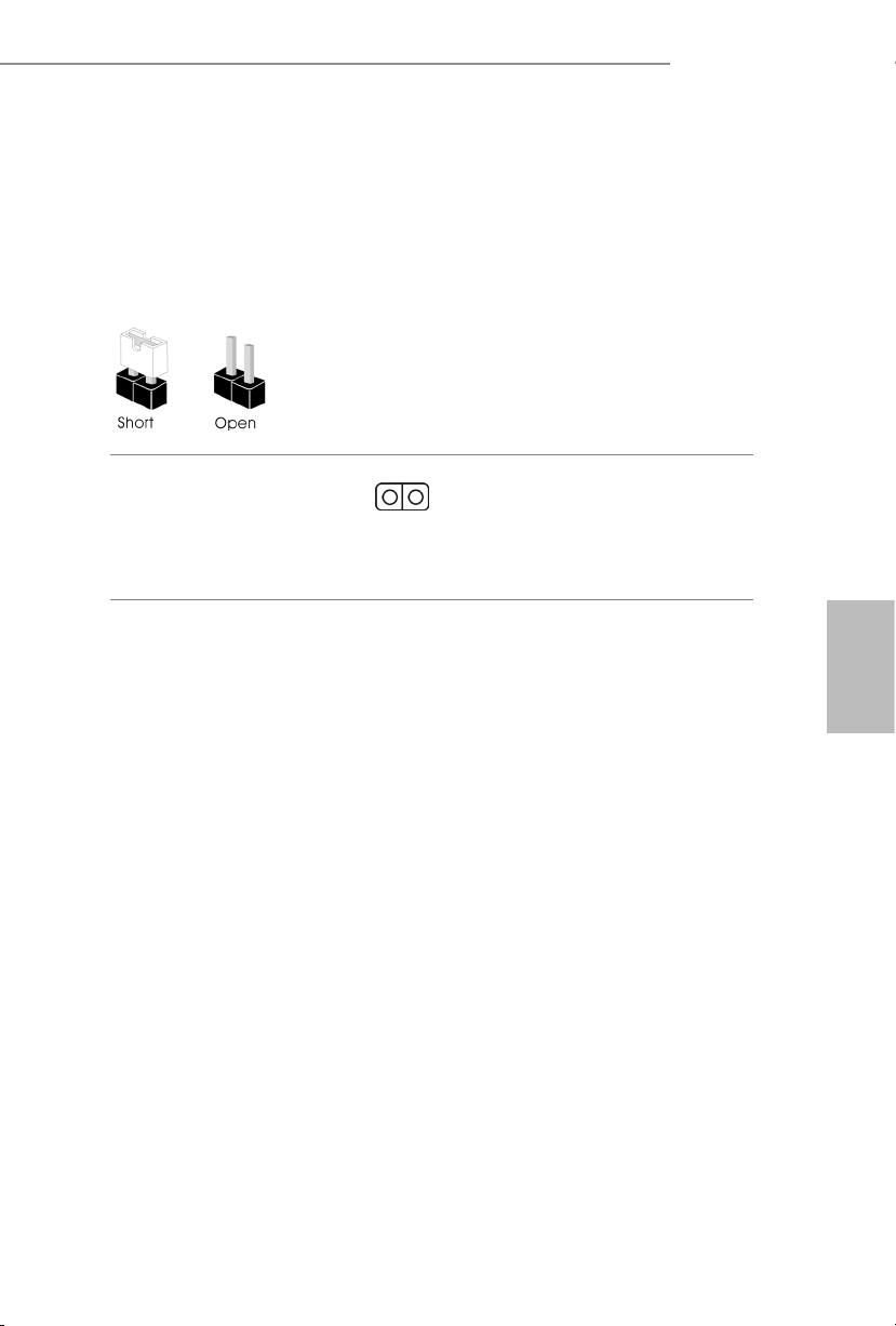
H610M-ITX/ac
1.3 Ustawienia zworek
Ta ilustracja pokazuje ustawienia zworek. Po umieszczeniu nasadki zworki na pinach,
zworka jest “Zwarta”. Jeśli nasadka zworki nie jest umieszczona na pinach, zworka jest
“Otwarta”.
Zworka usuwania danych
z pamięci CMOS
(CLRMOS1)
(sprawdź s.1, Nr 15)
CLRMOS1 umożliwia usunięcie wszystkich danych z pamięci CMOS. Aby usunąć i
zresetować parametry systemu do ustawień domyślnych, wyłącz komputer i odłącz
przewód zasilający od zasilania. Po odczekaniu 15 sekund, użyj nasadkę zworki do zwarcia
pinów CLRMOS1 na 5 sekund. Jednak, nie należy usuwać danych z pamięci CMOS zaraz
po wykonaniu aktualizacji BIOS. Jeśli wymagane jest usunięcie danych z pamięci CMOS
po zakończeniu aktualizacji BIOS, przed rozpoczęciem usuwania danych z pamięci CMOS
należy najpierw uruchomić system, a następnie wyłączyć go. Należy pamiętać, że hasło,
data, czas i domyślny prol użytkownika zostaną usunięte tylko po wyjęciu baterii CMOS.
Należy pamiętać, aby po usunięciu danych z pamięci CMOS, usunąć nasadkę zworki.
2-pinowa zworka
Polski
95
Page 100
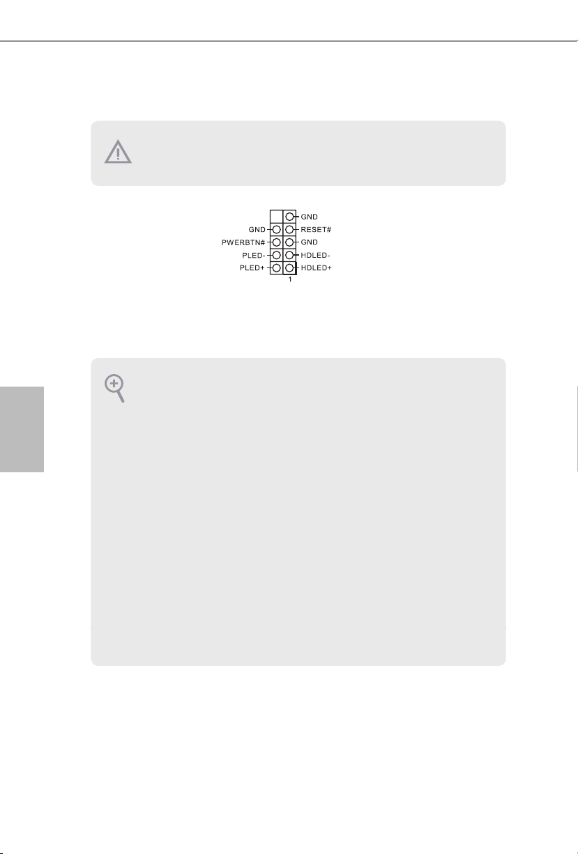
1.4 Wbudowane złącza główkowe i inne złącza
Wbudowane złącza główkowe i inne złącza są bezzworkowe. NIE należy umieszczać zworek
nad tymi złączami główkowymi i złączami. Umieszczanie zworek nad złączami główkowymi i
złączami spowoduje trwałe uszkodzenie płyty głównej.
Złącze główkowe na
panelu systemu
(9-pinowe PANEL1)
(sprawdź s.1, Nr 13)
Podłącz do tego złącza
główkowego przełącznik zasilania,
przełącznik resetowania i
wskaźnik stanu systemu na
obudowie, zgodnie z pokazanym
poniżej przydziałem pinów. Przed
podłączeniem kabli należy zapisać
pozycję pinów plus i minus.
PWRBTN (Przełącznik zasilania):
Podłącz do przełącznika zasilania na panelu przednim obudowy. Można skongurować sposób
Polski
wyłączania systemu z użyciem przełącznika zasilania.
RESET (Przełącznik resetowania):
Podłącz do przełącznika resetowania na panelu przednim obudowy. Naciśnij przełącznik
resetowania w celu ponownego uruchomienia komputera, jeśli komputer zawiesi się i nie
wykona normalnego ponownego uruchomienia.
PLED (Dioda LED zasilania systemu):
Podłączenie do wskaźnika stanu zasilania na panelu przednim obudowy. Ta dioda LED jest
włączona podczas działania systemu. Ta dioda LED miga, gdy system znajduje się w stanie
uśpienia S1/S3. Ta dioda LED jest wyłączona, gdy system znajduje się w stanie uśpienia S4 lub
wyłączenia zasilania (S5).
HDLED (Dioda LED aktywności dysku twardego):
Podłączenie do diody LED aktywności dysku twardego na panelu przednim obudowy. Dioda
LED jest włączona, podczas odczytu lub zapisu danych przez dysk twardy.
Konstrukcja panelu przedniego zależy od obudowy. Moduł panelu przedniego zawiera przede
wszystkim przełącznik zasilania, przełącznik resetowania, diodę LED zasilania, diodę LED
aktywności dysku twardego, głośnik, itd. Po podłączeniu modułu panelu przedniego obudowy
do tego złącza główkowego upewnij się, że jest prawidłowo dopasowany przydział przewodów
i przydział pinów.
96
 Loading...