


Version 1.0
Published July 2015
Copyright©2015 ASRock INC. All rights reserved.
Copyright Notice:
No part of this documentation may be reproduced, transcribed, transmitted, or
translated in any language, in any form or by any means, except duplication of
documentation by the purchaser for backup purpose, without written consent of
ASRock Inc.
Products and corporate names appearing in this documentation may or may not
be registered trademarks or copyrights of their respective companies, and are used
only for identication or explanation and to the owners’ benet, without intent to
infringe.
Disclaimer:
Specications and information contained in this documentation are furnished for
informational use only and subject to change without notice, and should not be
constructed as a commitment by ASRock. ASRock assumes no responsibility for
any errors or omissions that may appear in this documentation.
With respect to the contents of this documentation, ASRock does not provide
warranty of any kind, either expressed or implied, including but not limited to
the implied warranties or conditions of merchantability or tness for a particular
purpose.
In no event shall ASRock, its directors, ocers, employees, or agents be liable for
any indirect, special, incidental, or consequential damages (including damages for
loss of prots, loss of business, loss of data, interruption of business and the like),
even if ASRock has been advised of the possibility of such damages arising from any
defect or error in the documentation or product.
is device complies with Part 15 of the FCC Rules. Operation is subject to the following
two conditions:
(1) this device may not cause harmful interference, and
(2) this device must accept any interference received, including interference that
may cause undesired operation.
CALIFORNIA, USA ONLY
e Lithium battery adopted on this motherboard contains Perchlorate, a toxic substance
controlled in Perchlorate Best Management Practices (BMP) regulations passed by the
California Legislature. When you discard the Lithium battery in California, USA, please
follow the related regulations in advance.
“Perchlorate Material-special handling may apply, see www.dtsc.ca.gov/hazardouswaste/
perchlorate”
ASRock Website: http://www.asrock.com

e terms HDMI™ and HDMI High-Denition Multimedia Interface, and the HDMI
logo are trademarks or registered trademarks of HDMI Licensing LLC in the United
States and other countries.

Contents
Chapter 1 Introduction 1
1.1 Package Contents 1
1.2 Specications 2
1.3 Motherboard Layout 6
1.4 I/O Panel 8
Chapter 2 Installation 10
2.1 Installing the CPU 11
2.2 Installing the CPU Fan and Heatsink 14
2.3 Installing Memory Modules (DIMM) 15
2.4 Expansion Slots (PCI Express Slots) 17
2.5 Jumpers Setup 18
2.6 Onboard Headers and Connectors 19
Chapter 3 Software and Utilities Operation 23
3.1 Installing Drivers 23
3.2 A-Tuning 24
3.3 ASRock Live Update & APP Shop 28
3.3.1 UI Overview 28
3.3.2 Apps 29
3.3.3 BIOS & Drivers 32
3.3.4 Setting 33
3.4 Enabling USB Ports for Windows® 7 Installation 34

Chapter 4 UEFI SETUP UTILITY 37
4.1 Introduction 37
4.1.1 UEFI Menu Bar 37
4.1.2 Navigation Keys 38
4.2 Main Screen 39
4.3 OC Tweaker Screen 40
4.4 Advanced Screen 48
4.4.1 CPU Conguration 49
4.4.2 Chipset Conguration 51
4.4.3 Storage Conguration 54
4.4.4 Super IO Conguration 55
4.4.5 ACPI Conguration 56
4.4.6 USB Conguration 57
4.4.7 Trusted Computing 58
4.5 Tools 59
4.6 Hardware Health Event Monitoring Screen 63
4.7 Security Screen 65
4.8 Boot Screen 66
4.9 Exit Screen 69


H170M-ITX/DL
Chapter 1 Introduction
ank you for purchasing ASRock H170M-ITX/DL motherboard, a reliable
motherboard produced under ASRock ’s consistently stringent qualit y control.
It delivers excellent performance with robust design conforming to ASRock’s
commitment to quality and endurance.
In this documentation, Chapter 1 and 2 contains the introduction of the
motherboard and step-by-step installation guides. Chapter 3 contains the operation
guide of the soware and utilities. Chapter 4 contains the conguration guide of
the BIOS setup.
Becau se the motherboard speci cations and the BIOS soware might be updated, the
content of this doc umentation will be subject to change without notice. In case any modications of this documentation occur, the updated version will be available on ASRock’s
website w ithout further notice . If you require technical suppor t related to this motherboard, please v isit our website for specic information about the model you are using. You
may nd the l atest VGA cards and CPU support list on ASRock’s website as well . ASRock
website http://www.asrock.com.
1.1 Package Contents
ASRock H170M-ITX/DL Motherboard (Mini-ITX Form Factor)
•
ASRock H170M-ITX/DL Quick Installation Guide
•
ASRock H170M-ITX/DL Support CD
•
2 x Serial ATA (SATA) Data Cables (Optional)
•
1 x I/O Panel Shield
•
1 x WiFi Module Bracket
•
2 x Screws for WiFi Module
•
English

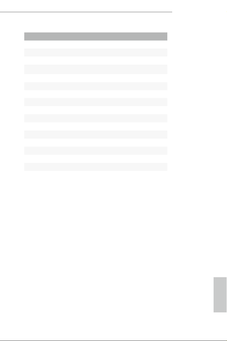
1.2 Specications
Platform
CPU
Chipset
Memory
Expansion
Slot
•
•
•
•
•
•
•
•
•
•
•
•
•
•
•
•
* is Mini-PCI Express Slot supports WiFi and mSATA
devices.
Mini-ITX Form Factor
Solid Capacitor design
High Density Glass Fabric PCB
Supports 6th Generation Intel® CoreTM i7/i5/i3/Pentium®/
Celeron® Processors (Socket 1151)
Digi Power design
6 Power Phase design
Supports Intel® Turbo Boost 2.0 Technolog y
Intel® H170
Supports Intel® Small Business Advantage 4.0
Dual Channel DDR4 Memory Technology
2 x DDR4 DIMM Slots
Supports DDR4 2133 non-ECC, un-buered memory
Max. capacity of system memory: 32GB
Supports Intel® Extreme Memory Prole (XMP) 2.0
1 x PCI Express 3.0 x16 Slot (PCIE1: x16 mode)
1 x Vertical Ha lf-size Mini-PCI Express Slot
Intel® HD Graphics Built-in Visuals and the VGA outputs
Graphics
English
•
can be supported only with processors which are GPU
integrated.
Supports Intel® HD Graphics Built-in Visuals : Intel® Quick
•
Sync Video with AVC, MVC (S3D) and MPEG-2 Full
HW Encode1, Intel® InTruTM 3D, Intel® Clear Video HD
Technology, Intel® InsiderTM, Intel® HD Graphics 510/530
Pixel Shader 5.0, DirectX 12
•
Max. shared memory 1792MB
•
Dual graphics output: Support DVI-D and HDMI ports by
•
independent display controllers
2 3

Audio
H170M-ITX/DL
Supports HDMI with max. resolution up to 4K x 2K
•
(4096x2304) @ 24Hz
Supports DVI-D with max. resolution up to 1920x1200 @
•
60Hz
Supports Auto Lip Sync, Deep Color (12bpc), xvYCC and
•
HBR (High Bit Rate Audio) with HDMI Port (Compliant
HDMI monitor is required)
Supports Accelerated Media Codecs: HEVC, VP8, VP9
•
Supports HDCP with DVI-D and HDMI Ports
•
Supports Full HD 1080p Blu-ray (BD) playback with DVI-D
•
and HDMI Ports
7.1 CH HD Audio with Content Protection (Realtek ALC892
•
Audio Codec)
* To congure 7.1 CH HD Audio, it is required to use an HD
front panel audio module and enable the multi-channel audio
feature through the audio driver.
Premium Blu-ray Audio support
•
Supports Surge Protection (ASRock Full Spike Protection)
•
ELNA Audio Caps
•
LAN
Rear Panel
I/O
1 x Intel® I219V (Gigabit LAN PHY 10/100/1000 Mb/s)
•
1 x Realtek RTL8111H (PCIE x1 Gigabit LAN 10/100/1000
•
Mb/s)
Supports Wake-On-WAN (on Realtek RTL8111H)
•
Supports Wake-On-LAN
•
Supports Lightning/ESD Protection (ASRock Full Spike
•
Protection)
Supports LAN Cable Detection (on Realtek RTL8111H)
•
Supports Energy Ecient Ethernet 802.3az
•
Supports PXE
•
1 x PS/2 Mouse/Keyboard Port
•
1 x DVI-D Port
•
1 x HDMI Port
•
2 x USB 2.0 Ports (Supports ESD Protection (ASRock Full
•
Spike Protection))
English

Storage
Connector
6 x USB 3.0 Ports (Supports ESD Protection (ASRock Full
•
Spike Protection))
2 x RJ-45 LAN Ports with LED (ACT/LINK LED and SPEED
•
LED)
HD Audio Jacks: Line in / Front Speaker / Microphone
•
4 x SATA3 6.0 Gb/s Connectors, support R AID (R AID 0,
•
RAID 1, RAID 5, RAID 10, Intel Rapid Storage Technology
14 and Intel Smart Response Technology), NCQ, AHCI and
Hot Plug
1 x mSATA Connector (shared with Mini-PCI Express Slot),
•
support R AID (RAID 0, R AID 1, RAID 5, RAID 10, Intel
Rapid Storage Technology 14 and Intel Smart Response
Technology), NCQ, AHCI and Hot Plug
1 x TPM Header
•
1 x Chassis Intrusion Header
•
1 x CPU Fan Connector (4-pin) (Smart Fan Speed Control)
•
1 x Chassis Fan Connector (4-pin) (Smart Fan Speed
•
Control)
1 x 20 pin ATX Power Connector
•
1 x 4 pin 12V Power Connector
•
1 x Front Panel Audio Connector
•
1 x USB 2.0 Header (Supports 2 USB 2.0 ports) (Supports
•
ESD Protection (ASRock Full Spike Protection))
1 x USB 3.0 Header (Supports 2 USB 3.0 ports) (Supports
•
ESD Protection (ASRock Full Spike Protection))
128Mb AMI UEFI Legal BIOS with multilingual GUI
BIOS
Feature
•
support
ACPI 1.1 Compliant wake up events
•
SMBIOS 2.3.1 Support
•
CPU, GT_CPU, DRAM, PCH 1.0V, VCCIO, VPPM, VCCSA
•
Voltage Multi-adjustment
English
CPU/Chassis temperature sensing
Hardware
Monitor
4 5
•
CPU/Chassis Fan Tachometer
•
CPU/Chassis Quiet Fan (Auto adjust chassis fan speed by
•
CPU temperature)
CPU/Chassis Fan multi-speed control
•
CASE OPEN detection
•
Voltage monitoring: +12V, +5V, +3.3V, CPU Vcore
•
Microso® Windows® 10 64-bit / 8.1 64-bit / 7 32-bit / 7 64-
OS
•
bit
* To install Windows® 7 OS, a modied installation disk with
xHCI drivers packed into the ISO le is required. Please refer to
page 34 for more detailed instructions.
* For the updated Windows® 10 driver, please visit ASRock’s
website for details: http://www.asrock.com
FCC, CE, WHQL
Certications
* For detailed product information, please visit our website: http://www.asrock .com
•
ErP/EuP Ready (ErP/EuP ready power supply is required)
•
H170M-ITX/DL
Please realize that there i s a certain risk involved with o verclocking, including adjusting
the setting in the BIOS , applying Untied Overclocking Technology, or using third-party
overclocking tools. Overclocking may aect your system’s stability, or even cau se damage to
the components and devices of your system. It should be done at your own r isk and expense.
We are not responsible for possible damage caused b y overclocking.
English
PCIE1
DDR 4_A1 (6 4 bit, 28 8-pin m odule )
DDR 4_B1 (6 4 bit, 28 8-pin m odule )
CPU_FAN1
CHA_FAN1
5
RoHS
H170M-ITX/DL
2
6
7
9
10
8
USB 2.0
T: USB1
B: USB2
PS2
Keyb oard
/Mou se
15 14 13 12 11
MINI_PCIE1
128Mb
BIOS
AUDIO
CODEC
4
17
1
HD_AUDIO1
1
USB_3_ 4
1
SPEAKER 1
Top:
RJ-45
USB 3.0
T: USB1
B: USB2
Top:
RJ-45
USB 3.0
T: USB3
B: USB4
USB 3.0
T: USB5
B: USB6
LAN
LAN
Intel
H170
ATXP WR 1
SATA3_3
SATA3_2
SATA3_1
SATA3_0
USB3_7 _8
1
31
PANEL1
HDLED RESET
PLED PWRBTN
1
TPMS1
1
1
CLRMOS1
1
CI1
16
HDM I1
DVI 1
Top:
LINE I N
Cent er:
FRON T
Bott om:
MIC IN
Front U SB 3.0
PCI Express 3.0
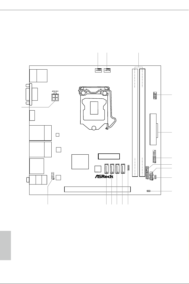
1.3 Motherboard Layout
English
6 7
No. Description
1 Chassis Fan Connector (CHA_FAN1)
2 CPU Fan Connector (CPU_FAN1)
3 2 x 288-pin DDR4 DIMM Slots (DDR4_A1, DDR4_B1)
4 USB 2.0 Header (USB_ 3_4)
5 ATX Power Connector (ATXPWR1)
6 USB 3.0 Header (USB3_7_8)
7 TPM Header (TPMS1)
8 System Panel Header (PANEL1)
9 Clear CMOS Jumper (CLRMOS1)
10 Chassis Intrusion Header (CI1)
11 Chassis Speaker Header (SPEAKER1)
12 SATA3 Connector (SATA3_0)
13 SATA3 Connector (SATA3_1)
14 SATA3 Connector (SATA3_2)
15 SATA3 Connector (SATA3_3)
16 Front Panel Audio Header (HD_AUDIO1)
17 ATX 12V Power Connector (ATX12V1)
H170M-ITX/DL
English
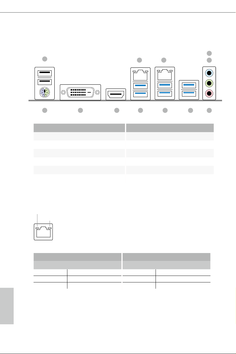
1.4 I/O Panel
1
2 3
12 891011
No. Description No. Description
1 USB 2.0 Ports (USB12) 7 USB 3.0 Ports (USB3_56)
2 LAN RJ-45 Port (Realtek RTL8111H)* 8 USB 3.0 Ports (USB3_34)
3 LAN RJ-45 Port (Intel® I219V)* 9 USB 3.0 Ports (USB3_12)
4 Line In (Light Blue)** 10 HDMI Port
5 Front Speaker (Lime)** 11 DVI-D Port
6 Microphone (Pink)** 12 PS/2 Mouse/Keyboard Port
* ere are two LEDs on each LAN port. Plea se refer to the table below for the LAN port LED indications.
ACT/LINK LED
SPEED LED
4
5
67
LAN Por t
Activity / Link LED Speed LED
Status Description Status Description
O No Link O 10Mbps connection
Blinking Data Activity Orange 100Mbps connection
On Link Green 1Gbps connection
English
8 9

H170M-ITX/DL
** To congure 7.1 CH HD Audio, it i s required to use an HD front panel audio module and e nable the multichannel audio feature through the audio driver.
Please set Speaker Cong uration to “ 7.1 Speaker” in the Realtek HD Audio Manager.
Function of the Audio Ports in 7.1-channel Conguration:
Port Function
Light Blue (Rear panel) Rear Speaker Out
Lime (Rear panel) Front Speaker Out
Pink (Rear panel) Central /Subwoofer Speaker Out
Lime (Front panel) Side Speaker Out
English

Chapter 2 Installation
is is a Mini-ITX form factor motherboard. Before you install the motherboard,
study the conguration of your chassis to ensure that the motherboard ts into it.
Pre-installation Precautions
Take note of the following precautions before you install motherboard components
or change any motherboard settings.
Make sure to unplug the power cord before installing or removing the motherboard
•
components. Failure to do so may cause physical injuries and damages to motherboard
components.
In order to avoid damage from static electricity to the motherboard’s components,
•
NEVER place your motherboard directly on a carpet. Also remember to use a grounded
wrist strap or touch a safety grounded object before you handle the components.
Hold components by the edges and do not touch the ICs.
•
Whenever you uninstall any components, place them on a grounded anti-static pad or
•
in the bag that comes with the components.
When placing screws to secure the motherboard to the chassis, please do not over-
•
tighten the screws! Doing so may damage the motherboard.
English
10 11

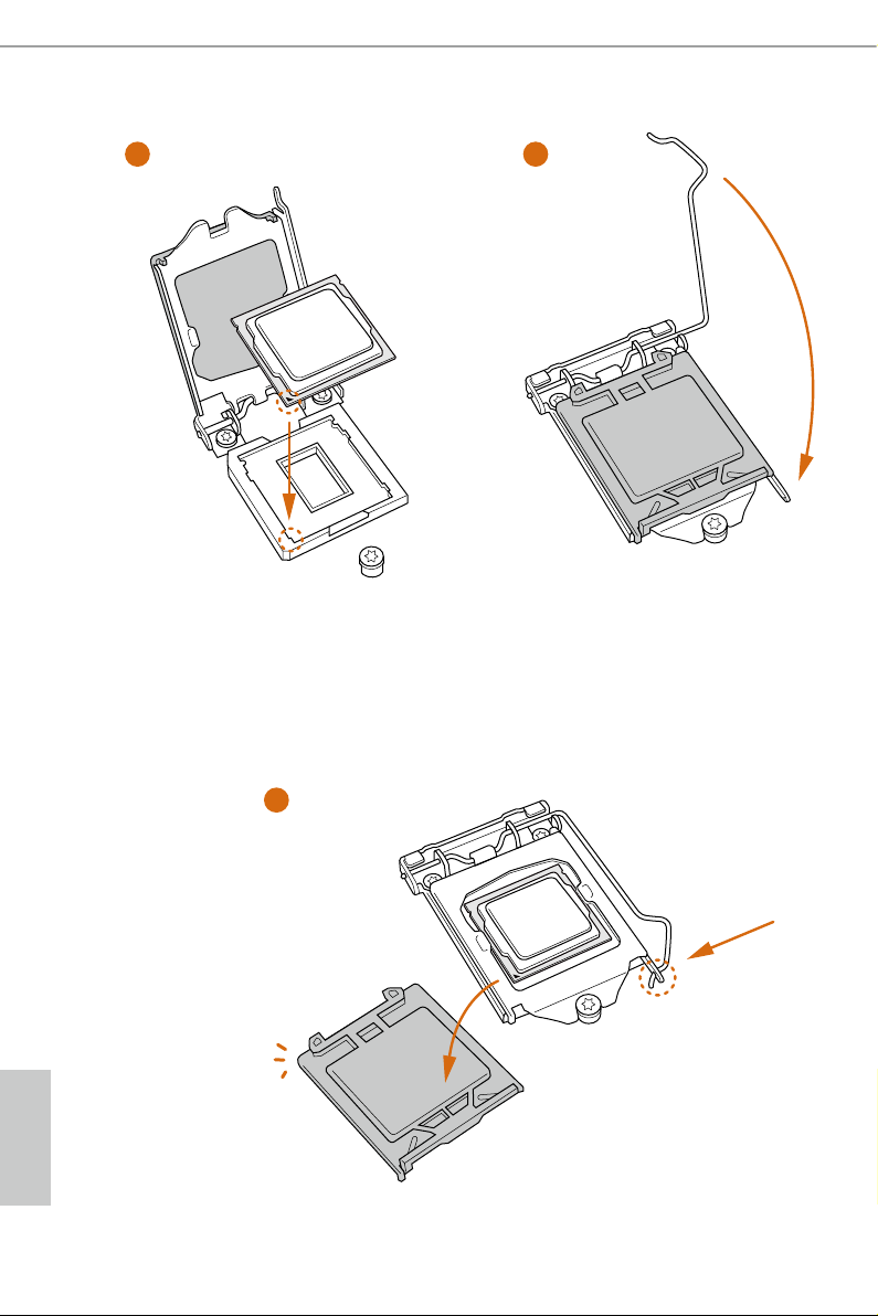
2.1 Installing the CPU
1. Before you insert the 1151-Pin CPU into the socket , please check if the PnP cap is on the
socket, if the CPU sur face is unclean, or if the re are any bent pins in the socket . Do not
force to in sert the CPU into the socket if above situation is found. Otherwise, the CPU
will be seriously damaged.
2. Unplug all power c ables be fore installing the CPU.
1
H170M-ITX/DL
A
B
2
English
3
4
5
English
12 13

Please save and replace the cover if the processor is removed. e cove r must be placed if
you wish to return the motherboard for ae r service.
H170M-ITX/DL
English
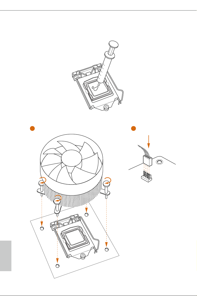
2.2 Installing the CPU Fan and Heatsink
1 2
FAN
CPU_
English
14 15
2.3 Installing Memory Modules (DIMM)
is motherboard provides two 288-pin DDR4 (Double Data Rate 4) DIMM slots.
It is not allowed to install a DDR, DDR2 or DDR3 memory module into a DDR4 slot; otherwise, this motherboard and DIMM may be d amaged .
e DIMM only ts in one correct orientation. It wil l cause permane nt damage to the
motherboard and the DIMM if you force the DIMM into the slot at incorrect orie ntation .
H170M-ITX/DL
English

1
2
3
English
16 17
2.4 Expansion Slots (PCI Express Slots)
ere is 1 PCI Express slot and 1 mini-PCI Express slot on the motherboard.
Before installing an expansion card, plea se make sure that the power supply is sw itched o
or the power cord is unplugged. Please read the documentation of the expansion card and
make necessary hardware settings for the card before you start the installation.
PCIe slot:
PCIE1 (PCIe 3.0 x16 slot) is used for PCI Express x16 lane width graphics cards.
mini-PCIe slot:
H170M-ITX/DL
MINI_PCIE1 (mini-PCIe slot) is used for WiFi module.
* is Mini-PCI Express Slot supports WiFi and mSATA devices.
English
 Loading...