


Version 1.0
Published May 2016
Copyright©2016 ASRock INC. All rights reserved.
Copyright Notice:
No part of this documentation may be reproduced, transcribed, transmitted, or
translated in any language, in any form or by any means, except duplication of
documentation by the purchaser for backup purpose, without written consent of
ASRock Inc.
Products and corporate names appearing in this documentation may or may not
be registered trademarks or copyrights of their respective companies, and are used
only for identication or explanation and to the owners’ benet, without intent to
infringe.
Disclaimer:
Specications and information contained in this documentation are furnished for
informational use only and subject to change without notice, and should not be
constructed as a commitment by ASRock. ASRock assumes no responsibility for
any errors or omissions that may appear in this documentation.
With respect to the contents of this documentation, ASRock does not provide
warranty of any kind, either expressed or implied, including but not limited to
the implied warranties or conditions of merchantability or tness for a particular
purpose.
In no event shall ASRock, its directors, ocers, employees, or agents be liable for
any indirect, special, incidental, or consequential damages (including damages for
loss of prots, loss of business, loss of data, interruption of business and the like),
even if ASRock has been advised of the possibility of such damages arising from any
defect or error in the documentation or product.
is device complies with Part 15 of the FCC Rules. Operation is subject to the following
two conditions:
(1) this device may not cause harmful interference, and
(2) this device must accept any interference received, including interference that
may cause undesired operation.
CALIFORNIA, USA ONLY
e Lithium battery adopted on this motherboard contains Perchlorate, a toxic substance
controlled in Perchlorate Best Management Practices (BMP) regulations passed by the
California Legislature. When you discard the Lithium battery in California, USA, please
follow the related regulations in advance.
“Perchlorate Material-special handling may apply, see ww w.dtsc.ca.gov/hazardouswaste/
perchlorate”
ASRock Website: http://www.asrock.com

AUSTRALIA ONLY
Our goods come with guarantees that cannot be excluded under the Australian Consumer
Law. You are entitled to a replacement or refund for a major failure and compensation for
any other reasonably foreseeable loss or damage caused by our goods. You are also entitled
to have the goods repaired or replaced if the goods fail to be of acceptable quality and the
failure does not amount to a major failure. If you require assistance please call ASRock Tel
: +886-2-28965588 ext.123 (Standard International call charges apply)
e terms HDMI™ and HDMI High-Denition Multimedia Interface, and the HDMI
logo are trademarks or registered trademarks of HDMI Licensing LLC in the United
States and other countries.

Contents
Chapter 1 Introduction 1
1.1 Package Contents 1
1.2 Specications 2
1.3 Motherboard Layout 6
1.4 I/O Panel 8
Chapter 2 Installation 9
2.1 Installing the CPU 10
2.2 Installing the CPU Fan and Heatsink 13
2.3 Installing Memory Modules (SO-DIMM) 14
2.4 Expansion Slots (PCI Express Slot) 15
2.5 Jumpers Setup 16
2.6 Onboard Headers and Connectors 17
2.7 M.2 WiFi/BT Module Installation Guide 23
Chapter 3 Software and Utilities Operation 25
3.1 Installing Drivers 25
3.2 ASRock Live Update & APP Shop 26
3.2.1 UI Overview 26
3.2.2 Apps 27
3.2.3 BIOS & Drivers 30
3.2.4 Setting 31
3.3 Enabling USB Ports for Windows® 7 Installation 32

Chapter 4 UEFI SETUP UTILITY 35
4.1 Introduction 35
4.2 EZ Mode 36
4.3 Advanced Mode 37
4.3.1 UEFI Menu Bar 37
4.3.2 Navigation Keys 38
4.4 Main Screen 39
4.5 OC Tweaker Screen 40
4.6 Advanced Screen 47
4.6.1 CPU Conguration 48
4.6.2 Chipset Conguration 50
4.6.3 Storage Conguration 53
4.6.4 Super IO Conguration 54
4.6.5 ACPI Conguration 55
4.6.6 USB Conguration 56
4.6.7 Trusted Computing 57
4.7 Tools 58
4.8 Hardware Health Event Monitoring Screen 61
4.9 Security Screen 62
4.10 Boot Screen 63
4.11 Exit Screen 66
Chapter 1 Introduction
ank you for purchasing ASRock H110TM-ITX motherboard, a reliable
motherboard produced under ASRock’s consistently stringent quality control.
It delivers excellent performance with robust design conforming to ASRock’s
commitment to quality and endurance.
In this documentation, Chapter 1 and 2 contains the introduction of the
motherboard and step-by-step installation guides. Chapter 3 contains the operation
guide of the soware and utilities. Chapter 4 contains the conguration guide of
the BIOS setup.
Becau se the motherboard specications and the BIOS soware might be updated, the
content of this documentation will be subject to change without notice. In case any modications of this documentation occur, the updated version will be available on ASRock’s
website w ithout further notice. If you require technical support related to this motherboard, please visit our website for specic information about the model you are using. You
may nd the l atest VGA cards and CPU suppor t list on ASRock’s website a s well. ASRock
website http://www.asrock.com.
H110TM-ITX
1.1 Package Contents
ASRock H110TM-ITX Motherboard (in Mini-ITX Form Factor)
•
ASRock H110TM-ITX Quick Installation Guide
•
ASRock H110TM-ITX Support CD
•
2 x Serial ATA (SATA) Data Cables (Optional)
•
1 x SATA 1 to 2 Power Cable (Optional)
•
2 x I/O Panel Shields
•
1 x Screw for M.2 Socket
•
1 x Screw for mSATA Connector
•
English

1.2 Specications
Platform
CPU
Chipset
Memory
Expansion
Slot
•
•
•
•
•
•
•
•
•
•
•
•
•
•
•
* Supports NVMe SSD as boot disks
•
* e M.2 socket does not support SATA M.2 SSDs.
in Mini-ITX Form Factor
Solid Capacitor design
Supports 6th Generation Intel® CoreTM i7/i5/i3/Pentium®/
Celeron® Processors (Socket 1151)
Supports CPU up to 65W
Digi Power design
5 Power Phase design
Supports Intel® Turbo Boost 2.0 Technology
Intel® H110
Dual Channel DDR4 Memory Technology
2 x DDR4 SO-DIMM Slots
Supports DDR4 2133 non-ECC, un-buered memory
Supports ECC SO-DIMM memory modules (operate in non-
ECC mode)
Max. capacity of system memory: 32GB
Supports Intel® Extreme Memory Prole (XMP) 2.0
1 x PCI Express 3.0 x4 Slot
1 x M.2 Socket (Key E), supports ty pe 2230 WiFi/BT module
Intel® HD Graphics Built-in Visua ls and the VGA outputs
Graphics
English
•
can be supported only with processors which are GPU
integrated.
Supports Intel® HD Graphics Built-in Visuals : Intel® Quick
•
Sync Video with AVC, MVC (S3D) and MPEG-2 Full
HW Encode1, Intel® InTruTM 3D, Intel® Clear Video HD
Technology, Intel® InsiderTM, Intel® HD Graphics 510/530
Pixel Shader 5.0, DirectX 12
•
Max. shared memory 1024MB
•
* e size of ma ximum shared memory may vary from dierent
operating systems.
2 3

Audio
H110TM-ITX
ree graphics output options: HDMI, DVI-D and LVDS
•
Supports HDMI with max. resolution up to 4K x 2K
•
(4096x2160) @ 24Hz / (3840x2160) @ 30Hz
Supports DVI-D with ma x. resolution up to 1920x1200 @
•
60Hz
Supports LVDS with max. resolution up to 1920x1200 @
•
60Hz
Supports Auto Lip Sync, Deep Color (12bpc), xvYCC and
•
HBR (High Bit Rate Audio) with HDMI Port (Compliant
HDMI monitor is required)
Supports Accelerated Media Codecs: HEVC, VP8, VP9
•
Supports HDCP with DVI-D and HDMI Ports
•
Supports Full HD 1080p Blu-ray (BD) playback with DVI-D
•
and HDMI Ports
7.1 CH HD Audio with Content Protection (Realtek ALC892
•
Audio Codec)
* To congure 7.1 CH HD Audio, it is required to use an HD
front panel audio module and enable the multi-channel audio
feature through the audio driver.
Premium Blu-ray Audio support
•
Supports Surge Protection (ASRock Full Spike Protection)
•
ELNA Audio Caps
•
LAN
Rear Panel
I/O
Gigabit LAN 10/100/10 00 Mb/s
•
Giga PHY Intel® I219V
•
Supports Wake-On-LAN
•
Supports Lightning/ESD Protection (ASRock Full Spike
•
Protection)
Supports Energy Ecient Ethernet 802.3az
•
Supports PXE
•
1 x DC Jack (Compatible with the 19V power adapter)
•
1 x DVI-D Port
•
1 x HDMI Port
•
2 x USB 2.0 Ports (Supports ESD Protection (ASRock Full
•
Spike Protection))
2 x USB 3.0 Ports (Supports ESD Protection (ASRock Full
•
Spike Protection))
English

English
Storage
Connector
1 x RJ-45 LAN Port with LED (ACT/LINK LED and SPEED
•
LED)
HD Audio Jacks: Front Speaker / Microphone
•
2 x SATA3 6.0 Gb/s Connectors, support NCQ, AHCI and
•
Hot Plug
1 x mSATA Connector, support NCQ, AHCI and Hot Plug
•
* MINI_SATA1: RST utility port0; SATA3_0: RST utility port2;
SATA3_1: RST utility port3
1 x CIR Header
•
2 x COM Port Headers
•
1 x TPM Header
•
1 x SPDIF Out Connector
•
1 x Monitor Switch Header
•
1 x Backlight Power Jumper
•
1 x Panel Power Jumper
•
1 x Backlight & Amp Volume Control Header
•
1 x LVDS Connector
•
1 x Home eater PC Header
•
1 x CPU Fan Connector (4-pin)
•
1 x Chassis Fan Connector (4-pin) (Smart Fan Speed
•
Control)
* CHA_FAN1 can auto detect if 3-pin or 4-pin fan is in use.
* e CPU Fan Connector supports the CPU fan of ma ximum
1A (12W) fan power.
1 x Front Panel Audio Connector
•
1 x Analog Surround Audio Header
•
1 x Digital MIC Header
•
1 x 3W Audio AMP Output Wafer Header
•
1 x Internal Power Header
•
1 x SATA Power Connector
•
3 x USB 2.0 Headers (Support 5 USB 2.0 ports) (Supports
•
ESD Protection (ASRock Full Spike Protection))
1 x USB 3.0 Header (Supports 2 USB 3.0 ports) (Supports
•
ESD Protection (ASRock Full Spike Protection))
* USB3_4_5 is shared with USB4_5.
4 5
BIOS
Feature
Hardware
Monitor
OS
H110TM-ITX
AMI UEFI Legal BIOS with multilingual GUI support
•
ACPI 5.0 Compliant wake up events
•
SMBIOS 2.7 Support
•
DRAM Voltage Multi-adjustment
•
CPU/Chassis temperature sensing
•
CPU/Chassis Fan Tachometer
•
CPU/Chassis Quiet Fan (Auto adjust chassis fan speed by
•
CPU temperature)
CPU/Chassis Fan multi-speed control
•
Voltage monitoring: +12V, +5V, +3.3V, CPU Vcore
•
Microso® Windows® 10 64-bit / 8.1 64-bit / 7 32-bit / 7 64-
•
bit
* To install Windows® 7 OS, a modied installation disk with
xHCI drivers packed into the ISO le is required. Please refer to
page 32 or more detailed instructions.
* For the updated Windows® 10 driver, please visit ASRock ’s
website for details: http://ww w.asrock.com
FCC, CE, WHQL
Certications
* For detailed product information, please visit our website: http://www.asrock .com
Please realiz e that the re is a certain r isk involved with o verclocking, including adjusting
the setting in the BIOS, applying Untied Overclocking Technolog y, or using third-party
overclocking to ols. O verclocking may aect your system’s stability, or even c ause damage to
the components and devices of your system. It should be don e at your ow n risk and expense.
We are not responsibl e for possible damage caused by overclo cking.
•
ErP/EuP Ready (ErP/EuP ready power supply is required)
•
English
Intel
H110
PCIE1
MINI_SATA1
CMOS
Battery
SATA_POW1
LVDS 1
DDR4_B1
DDR4_A1
HDLED RESET
PLED PWRBTN
PANEL1
1
BKT_PWR1
1
PNL_PWR1
1
USB2_3
1
1
HDMI_SPDIF1
1
HD_AUDIO1
AUDIO
CODEC
LAN
SATA3_0
CPU_FAN1
BIOS
ROM
DMIC1
1
CLRCMOS1
1
Front
Speaker
Mic In
USB 2.0
T: USB0
B: USB1
RJ-45
USB 3.0
T: USB0
B: USB1
DC Jack
DVI1
HDM I1
CHA_FAN1
CIR1
H110TM-ITX
RoHS
1
HTPC1
BLT_VOL1
1
1
HD_AUDIO2
42
SATA3_1
5
6
7 9
10
11
15
17
18
19
16
20
25 21
23
26
27
28
22
13
14
12
3
1
USB6
1
MONITOR_SWITCH1
SPEAKER1
1
24
ATX19V_IN1
1
USB3_4_5
1
COM1
1
COM2
PCI Ex pre ss 3.0
1
TPMS1
8
M2
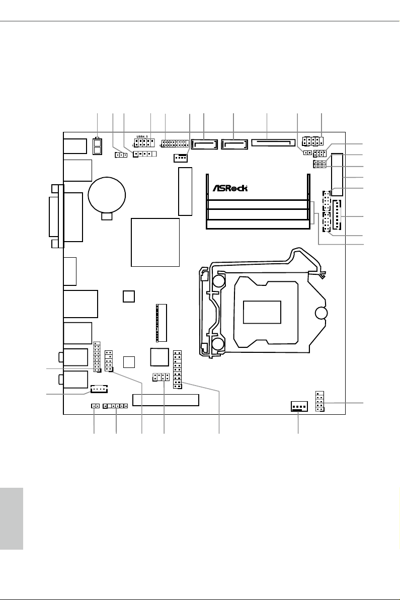
1.3 Motherboard Layout
English
6 7

No. Description
1 Internal Power Header (ATX19V_IN1)
2 Clear CMOS Jumper (CLRCMOS1)
3 USB 2.0 Header (USB6)
4 USB 2.0 Header (USB4_5)
5 USB 3.0 Header (USB3_4_5)
6 Chassis Fan Connector (CHA_FAN1)
7 SATA3 Connector (SATA3_0)
8 SATA3 Connector (SATA3_1)
9 SATA Power Connector (SATA_POW1)
10 Monitor Switch Header (MONITOR_SWITCH1)
11 System Panel Header (PANEL1)
12 Consumer Infrared Module Header (CIR1)
13 Backlight Power Jumper (BKT_PWR1)
14 Panel Power Jumper (PNL_PWR1)
15 LVDS Connector (LVDS1)
16 COM Port Header (COM2)
17 Backlight Control Header (BLT_VOL1)
18 COM Port Header (COM1)
19 2 x 260-pin DDR4 SO-DIMM Slots (DDR4_A1, DDR4_B1)
20 USB 2.0 Header (USB2_3)
21 CPU Fan Connector (CPU_FAN1)
22 TPM Header (TPMS1)
23 Home eater PC Header (HTPC1)
24 Front Panel Audio Header (HD_AUDIO1)
25 Digital MIC Header (DMIC1)
26 SPDIF Out Connector (HDMI_ SPDIF1)
27 3W Audio AMP Output Wafer Header (SPEAK ER1)
28 Analog Surround Audio Header (HD_AUDIO2)
H110TM-ITX
English
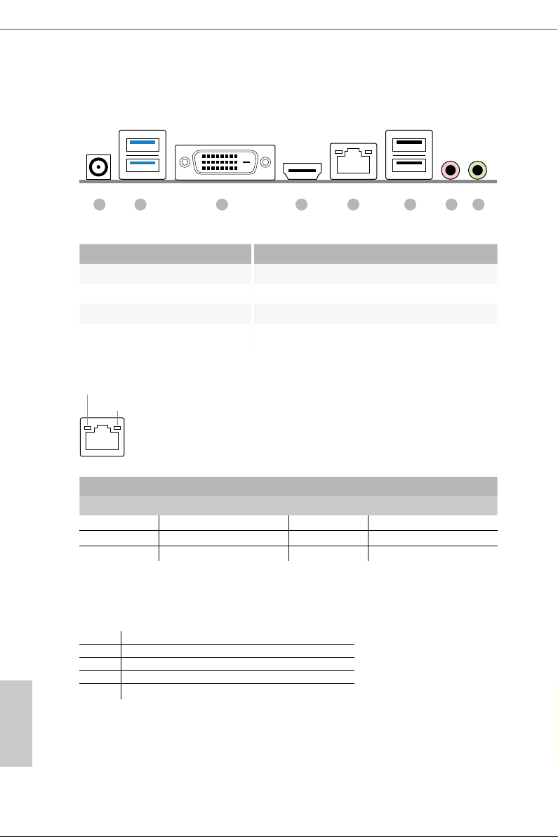
1.4 I/O Panel
No. Description No. Description
1 DC Jack** 5 LAN RJ-45 Port*
2 USB 3.0 Ports (USB3_01) 6 USB 2.0 Ports (USB01)
3 DVI-D Port (DVI1) 7 Microphone (Pink)
4 HDMI Port (HDMI1) 8 Front Speaker & Optical SPDIF Out (Lime)
*ere are two LEDs on each LAN port. Plea se refer to the table below for the LA N port LED indic ations.
ACT/LINK LED
SPEED LED
LAN Por t
Activity / Link LED Speed LED
Status Description Status Description
O No Link O 10Mbps connection
Blinking Data Activity Green 100Mbps connection
On Link Green 1Gbps connection
8762 5431
** Please use a 19V power a dapter for the DC jack. is jack accepts dual barrel plugs with an inner diameter of 5.1
mm and an outer diameter of 7.4 mm, where the inner contact is +19 (±10%) DC and the shell i s (centre pos itive).
DELTA DELTA-ADP-150TB-150W/19V
HP HP-TBC-BA52-150W/19V
FSP FSP-FSP150-ABAN1-150W/19V
DELL FA130PE1-00-130W/19.5V
English
DELL LA90PE0-01-90W/19.5V
Due to the power limitation and PCIe bandwidth (x4), the VGA card is not suppor ted.
is motherboard is available with support for either 2-pin ATX 19V power or DC-in power supplies. Please do
not use two kinds of power supplie s at the same time! Doing so may damage the motherboard component s and
devices. When you u se the DC-in power adapter, please use the onboard SATA power connector to get the powe r
for HDDs.
8 9

Chapter 2 Installation
is is a in Mini-ITX form factor motherboard. Before you install the
motherboard, study the conguration of your chassis to ensure that the
motherboard ts into it.
Pre-installation Precautions
Take note of the following precautions before you install motherboard components
or change any motherboard settings.
Make sure to unplug the power cord before installing or removing the motherboard
•
components. Failure to do so may cause physical injuries and damages to motherboard
components.
In order to avoid damage from static electricity to the motherboard’s components,
•
NEVER place your motherboard directly on a carpet. Also remember to use a grounded
wrist strap or touch a safety grounded object before you handle the components.
Hold components by the edges and do not touch the ICs.
•
Whenever you uninstall any components, place them on a grounded anti-static pad or
•
in the bag that comes with the components.
When placing screws to secure the motherboard to the chassis, please do not over-
•
tighten the screws! Doing so may damage the motherboard.
H110TM-ITX
English
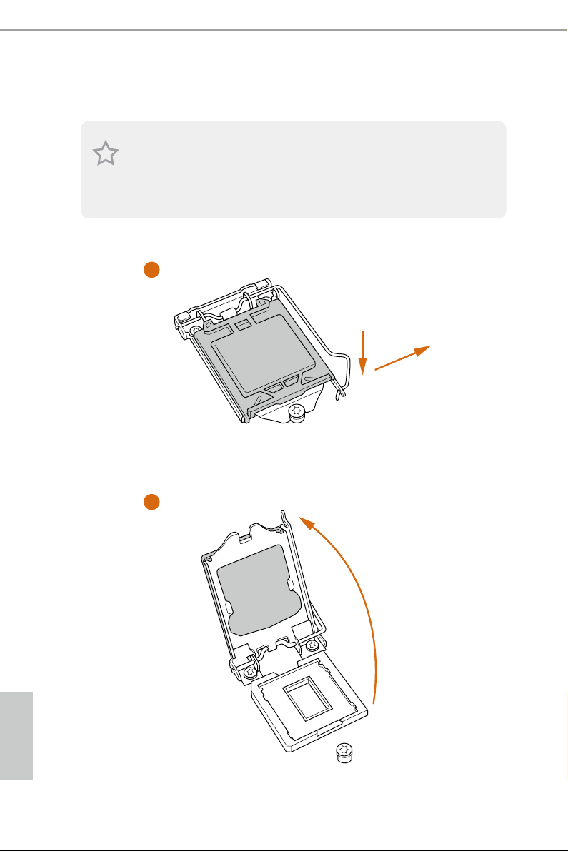
2.1 Installing the CPU
1. Before you insert the 1151-Pin CPU into the socket, please check if the P nP cap is on the
socket, if the CPU surface is unclean, or if there are any bent pins in the sock et. Do not
force to in sert the CPU into the socket if above situation is found . Otherwise, the CPU
will be seriously damaged.
2. Unplug all power c ables before in stalling the CPU.
1
2
A
B
English
10 11

H110TM-ITX
3
4
5
English

Please save and replace the cover if the processor i s removed. e cover must be placed if
you wish to return the motherboard for aer service.
English
12 13
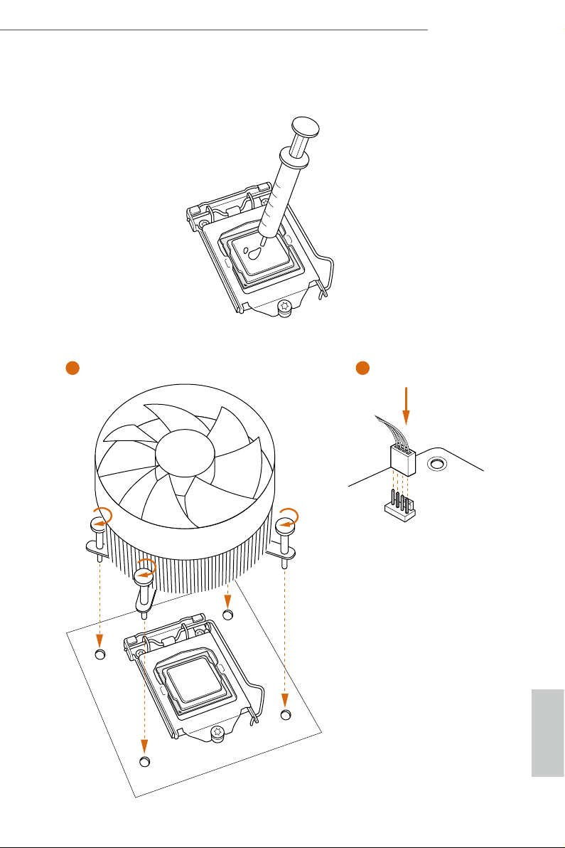
2.2 Installing the CPU Fan and Heatsink
1 2
H110TM-ITX
FAN
CPU_
English
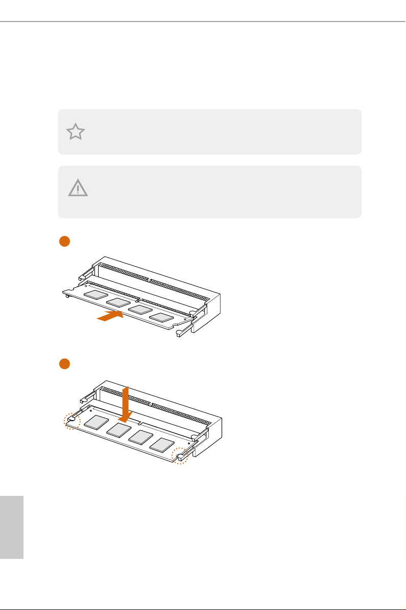
2.3 Installing Memory Modules (SO-DIMM)
1
is motherboard provides two 260-pin DDR4 (Double Data Rate 4) SO-DIMM
slots.
It is not allowed to install a DDR, DDR2 or DDR3 memory module into a DDR4 slot;
otherwise , this motherboard and SO-DIMM may be damaged.
e SO-DIMM only ts in one cor rect orientation. It w ill cause per manent damage to
the motherboard and the SO-DIMM if you force the SO-DIMM into the sl ot at incorrect
orientation.
2
English
14 15
2.4 Expansion Slots (PCI Express Slot)
ere is 1 PCI Express slot on the motherboard.
Before installing an ex pansion card, please make sure that the power supply is
switched o or the power cord is unplugged. Plea se read the documentation of the
expan sion card and mak e necessary h ardware settings for the card before you start
the installation.
PCIe slots:
PCIE1 (PCIe 3.0 x4 slot) is used for PCI Express x4 lane width graphics cards.
H110TM-ITX
English
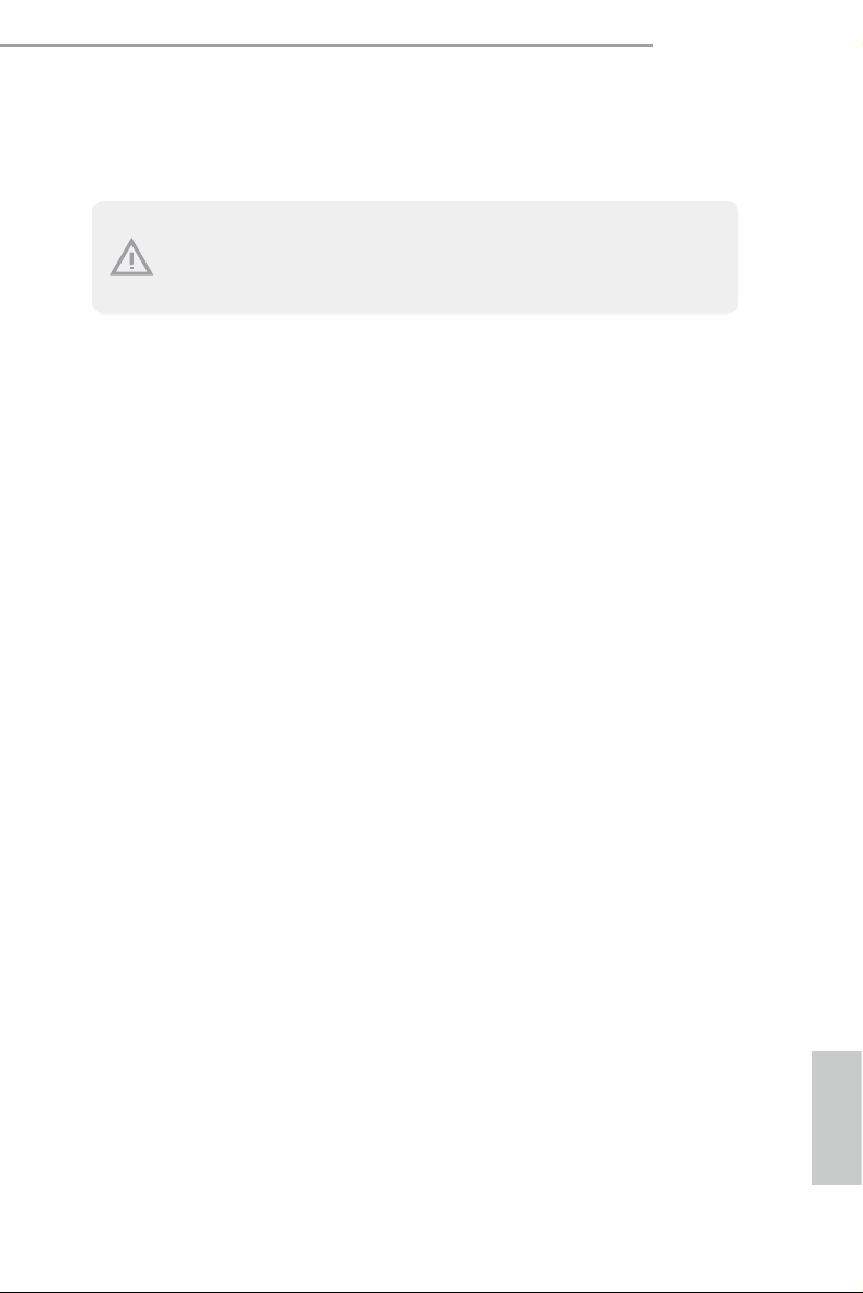
2.5 Jumpers Setup
e illustration shows how jumpers are setup. When the jumper cap is placed on
the pins, the jumper is “Short”. If no jumper cap is placed on the pins, the jumper
is “Open”. e illustration shows a 3-pin jumper whose pin1 and pin2 are “Short”
when a jumper cap is placed on these 2 pins.
Clear CMOS Jumper
(CLRCMO S1)
(see p.6, No. 2)
CLRCMOS1 allows you to clear the data in CMOS. To clear and reset the system
parameters to default setup, please turn o the computer and unplug the power
cord from the power supply. Aer waiting for 15 seconds, use a jumper cap to
short pin2 and pin3 on CLRCMOS1 for 5 seconds. However, please do not clear
the CMOS right aer you update the BIOS. If you need to clear the CMOS when
you just nish updating the BIOS, you must boot up the system rst, and then shut
it down before you do the clear-CMOS action. Please be noted that the password,
date, time, and user default prole will be cleared only if the CMOS battery is
removed.
Clear CMOSDefault
Backlight Power Jumper
(3-pin BKT_PWR1)
(see p.6, No. 13)
Panel Power Jumper
(3-pin PNL_PWR1)
(see p.6, No. 14)
1-2 : +19V
2-3 : +12V [Default]
1-2 : +3V
2-3 : +5V [Default]
English
War nin g:
If selected Back light Power or Panel Power is higher than panel's spec, it may damage the
panel.
16 17

2.6 Onboard Headers and Connectors
1
Onboard headers and connectors are NOT jump ers. Do NOT place jumper caps over these
heade rs and connectors. Placing jumper caps over the headers and connectors will cause
permanent damage to the motherboard.
H110TM-ITX
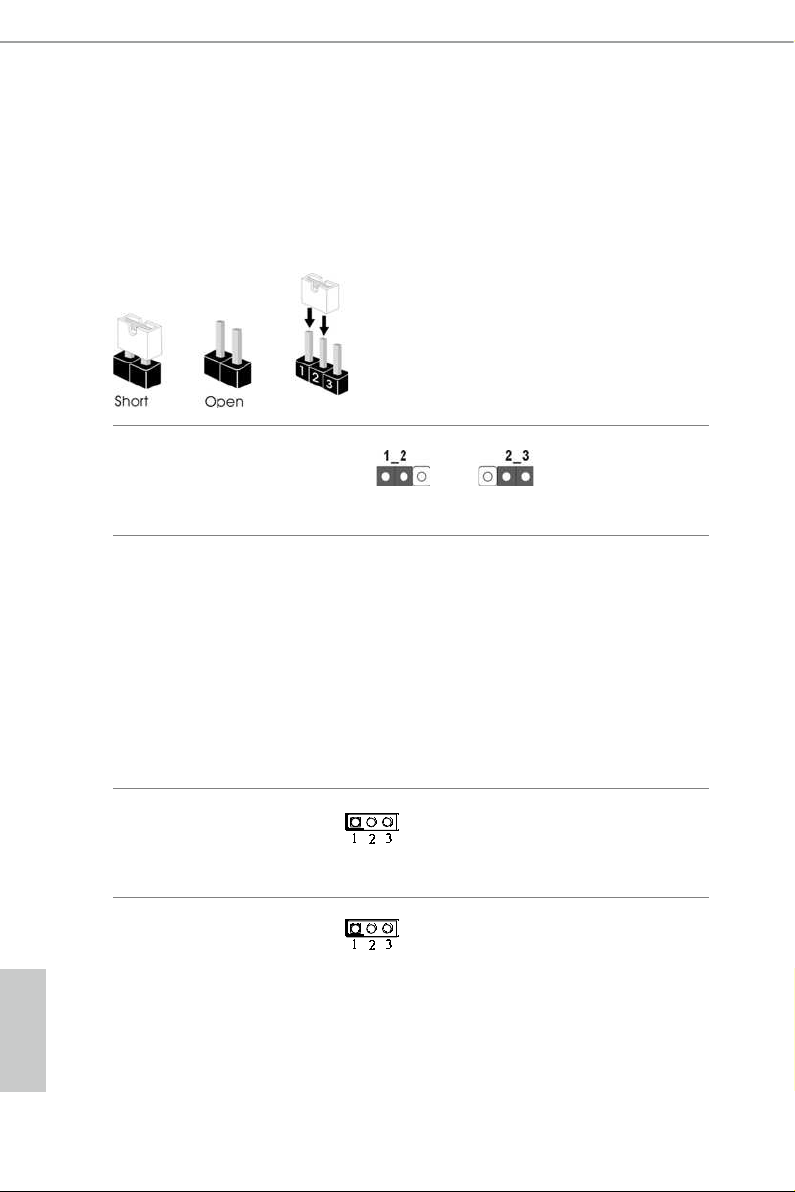
System Panel Header
(9-pi n PANEL1)
(see p.6, No. 11)
PWRBTN (Power Switch):
Connec t to the power switch on the ch assi s front panel. You may congure the way to tur n
o your system using the power switch.
RESET (Reset Switch):
Connec t to the reset switch on the chassi s front panel. Press the reset sw itch to restart the
computer if the computer f reezes and fails to per form a normal restar t.
PLED (Syste m Power LED):
Connec t to the power status indicator on the chas sis front panel. e LED i s on when the
system is operating. e LED keeps blinking when the system is in S1/S3 sleep state. e
LED is o when the system is in S4 slee p state or powered o (S5).
HDLED (Ha rd Drive Activity LED):
Connec t to the hard drive ac tivity LED on the chassis front panel. e LED is on when the
hard drive is reading or wr iting data.
e front panel de sign may dier by chassis. A front panel module mainly consists of powe r
switch, reset switch , power LED, hard dr ive activity LED, speaker and etc. When connecting your ch assi s front panel module to thi s header, make sure the wire a ssignments and the
pin assignments are matched correctly.
PLED+
PLED-
HDLED-
HDLED+
PWRBTN#
GND
RESET#
GND
GND
Connect the power
switch, reset switch and
system status indicator on
the chassis to this header
according to the pin
assignments below. Note
the positive and negative
pins before connecting
the cables.
Serial ATA3 Connectors
(SATA3_0:
see p.6, No. 7)
(SATA3_1:
see p.6, No. 8)
SATA3_0 SATA3_1
ese two SATA3
connectors support SATA
data cables for internal
storage devices with up to
6.0 Gb/s data transfer rate.
English
 Loading...