

Page 1

Version 1.0
Published August 2014
Copyright©2014 ASRock INC. All rights reserved.
Copyright Notice:
No part of this documentation may be reproduced, transcribed, transmitted, or
translated in any language, in any form or by any means, except duplication of
documentation by the purchaser for backup purpose, without written consent of
ASRock Inc.
Products and corporate names appearing in this documentation may or may not
be registered trademarks or copyrights of their respective companies, and are used
only for identication or explanation and to the owners’ benet, without intent to
infringe.
Disclaimer:
Specications and information contained in this documentation are furnished for
informational use only and subject to change without notice, and should not be
constructed as a commitment by ASRock. ASRock assumes no responsibility for
any errors or omissions that may appear in this documentation.
With respect to the contents of this documentation, ASRock does not provide
warranty of any kind, either expressed or implied, including but not limited to
the implied warranties or conditions of merchantability or tness for a particular
purpose.
In no event shall ASRock, its directors, ocers, employees, or agents be liable for
any indirect, special, incidental, or consequential damages (including damages for
loss of prots, loss of business, loss of data, interruption of business and the like),
even if ASRock has been advised of the possibility of such damages arising from any
defect or error in the documentation or product.
e terms HDMI™ and HDMI High-Denition Multimedia Interface, and the HDMI
logo are trademarks or registered trademarks of HDMI Licensing LLC in the United
States and other countries.
is device complies with Part 15 of the FCC Rules. Operation is subject to the following
two conditions:
(1) this device may not cause harmful interference, and
(2) this device must accept any interference received, including interference that
may cause undesired operation.
CALIFORNIA, USA ONLY
e Lithium battery adopted on this motherboard contains Perchlorate, a toxic substance
controlled in Perchlorate Best Management Practices (BMP) regulations passed by the
California Legislature. When you discard the Lithium battery in California, USA, please
follow the related regulations in advance.
“Perchlorate Material-special handling may apply, see ww w.dtsc.ca.gov/hazardouswaste/
perchlorate”
ASRock Website: http://www.asrock.com
Page 2
English
FM2A88X Pro3+
Motherboard Layout
SOCKET FM2b
2
3
1
21
Super
I/O
CMOS
BATTERY
PCIE1
LAN
AUDIO
CODEC
CPU_FAN1
CPU_FAN2
64Mb
BIOS
FM2A88X Pro3+
PCIE4
PCIE2
PCI1
PCI2
1
CLRCMOS1
HDLED RESET
PLED PWRBTN
1
PANEL1
SPEAKER1
1
PLED1
1
HD_AUDIO1
1
COM1
1
1
USB6_7
1
USB8_9
Top:
LINE IN
Cente r:
FRONT
Botto m:
MIC IN
RoHS
PS2
Mouse
PS2
Keyb oard
USB 3.0
T: USB2
B: USB3
RJ- 45 LAN
USB 2.0
T: USB4
B: USB5
CHA_FAN1
PCIE3
PCI Express 3.0
USB 2.0
T: USB0
B: USB1
ATX12V1
DDR 3_A1 (6 4 bit, 24 0-pin m odule )
DDR 3_A2 (6 4 bit, 24 0-pin m odule )
DDR 3_B1 (6 4 bit, 24 0-pin m odule )
DDR 3_B2 (6 4 bit, 24 0-pin m odule )
4
5
ATXP WR 1
6
CHA_FAN2
CHA_FAN3
PWR_FAN1
23
24
22
8
SATA_1_2
12
SATA_3_4
11
SATA_5_6
10
1314151617181920
PCIE5
AMD
A88X
(Bolton-D4)
Chipset
SATA_7_8
9
USB3_2 _3
7
PCIE_PWR1
VGA 1
DVI1
1
Page 3

English
No. Description
1 ATX 12V Power Connector (ATX12V1)
2 CPU Fan Connector (CPU_FAN1)
3 CPU Fan Connector (CPU_FAN2)
4 2 x 240-pin DDR3 DIMM Slots (DDR3_A1, DDR3_B1)
5 2 x 240-pin DDR3 DIMM Slots (DDR3_A2, DDR3_B2)
6 ATX Power Connector (ATXPWR1)
7 USB 3.0 Header (USB3_2_3)
8 Chassis Fan Connector (CHA_FAN2)
9 SATA 3 Con necto rs (SATA _7_ 8)
10 SATA 3 Con necto rs (SATA _ 5 _ 6)
11 SATA 3 Con necto rs (SATA _ 3 _ 4)
12 SATA3 Conn ector s (SATA _1_ 2)
13 System Panel Header (PANEL1)
14 Clear CMOS Jumper (CLRCMOS1)
15 Chassis Fan Connector (CHA_FAN3)
16 Power LED Header (PLED1)
17 Chassis Speaker Header (SPEAKER1)
18 USB 2.0 Header (USB8_9)
19 USB 2.0 Header (USB6_7)
20 COM Port Header (COM1)
21 Front Panel Audio Header (HD_AUDIO1)
22 Power Fan Connector (PWR_FAN1)
23 Chassis Fan Connector (CHA_FAN1)
24 PCIe Power Connector (PCIE_PWR1)
2
Page 4

English
FM2A88X Pro3+
I/O Panel
1 2 4
No. Description No. Description
1 PS/2 Mouse Port (Green) 7 USB 3.0 Ports (USB23)
2 LAN RJ-45 Port* 8 D-Sub Port (VGA1)
3 Line In (Light Blue) 9 DVI-D Port (DVI1)
4 Front Speaker (Lime) 10 USB 2.0 Ports (USB01)
5 Microphone (Pink) 11 PS/2 Keyboard Port (Purple)
6 USB 2.0 Ports (USB45)
3
567891011
3
Page 5

English
* There are two LED s on the L AN por t. Please refer to the table below for the L AN por t LED indica-
tions.
ACT/LINK LED
SPEED LED
LAN Por t
Activity / Link LED Speed LED
Status Description Status Description
Off No Link Off 10Mbps connection
Blinking Data Activity Orange 100Mbps connection
On Link Green 1Gbps connection
4
Page 6

English
FM2A88X Pro3+
1. Introduction
Thank you for purchasing ASRock FM2A88X Pro3+ motherboard, a reliable motherboard produced under ASRock’s consistently stringent quality control. It delivers
excellent performance with robust design conforming to ASRock’s commitment to
quality and endurance.
In this documentation, Chapter 1 and 2 contains the introduction of the motherboard
and step-by-step installation guides. Chapter 3 contains the operation guide of the
software and utilities. Chapter 4 contains the conguration guide of the BIOS setup.
Because the motherboard specications and the BIOS software might
be updated, the content of this manual will be subject to change without
notice. In case any modications of this manual occur, the updated version will be available on ASRock website without further notice. You may
nd the latest VGA cards and CPU support lists on ASRock website as
well. ASRock website http://www.asrock.com
If you require technical support related to this motherboard, please visit
our website for specic information about the model you are using.
www.asrock.com/support/index.asp
1.1 Package Contents
ASRock FM2A88X Pro3+ Motherboard (ATX Form Factor)
ASRock FM2A88X Pro3+ Quick Installation Guide
ASRock FM2A88X Pro3+ Support CD
2 x Serial ATA (SATA) Data Cables (Optional)
1 x I/O Panel Shield
5
Page 7

English
1.2 Specications
Platform
CPU
Chipset
Memory
Expansion
Slot
• ATX Form Factor
• All Solid Capacitor design
• High Density Glass Fabric PCB
• Supports Socket FM2+ 95W / FM2 100W processors
• 4 + 2 Power Phase design
• AMD A88X (Bolton-D4)
• Dual Channel DDR3 Memory Technology
• 4 x DDR3 DIMM Slots
• Supports DDR3 2400+(OC)/2133/1866/1600/1333/1066
non-ECC, un-buffered memory (see CAUTION 1)
• Max. capacity of system memory: 64GB (see CAUTION
2)
• Supports Intel® Extreme Memory Prole (XMP) 1.3 / 1.2
• SSupports AMD Memory Prole Technology (AMP) up
to AMP 2400
• 1 x PCI Express 3.0 x16 Slot (PCIE4 @ x16 mode)
* PCIE 3.0 is only supported with FM2+ CPU. With FM2
CPU, it only supports PCIE 2.0.
• 1 x PCI Express 2.0 x16 Slot (PCIE5 @ x4 mode)
• 3 x PCI Express 2.0 x1 Slots
• 2 x PCI Slots
• Supports AMD Quad CrossFireXTM, CrossFireXTM and
Dual Graphics
6
Graphics
• Integrated AMD RadeonTM R7/R5 Series Graphics in
A-series APU
• DirectX 11.1, Pixel Shader 5.0 with FM2+ CPU. DirectX
11, Pixel Shader 5.0 with FM2 CPU.
• Max. shared memory 2GB
• Dual VGA output: support DVI-D and D-Sub by
independent display controllers
• Supports Dual-link DVI-D with max. resolution up to
2560x1600 @ 60Hz
Page 8

English
FM2A88X Pro3+
• Supports D-Sub with max. resolution up to 1920x1200 @
60Hz
• Supports AMD Steady VideoTM 2.0: New video post
processing capability for automatic jitter reduction on
home/online video
• Supports HDCP with DVI-D Port
• Supports Full HD 1080p Blu-ray (BD) playback with
DVI-D Port
Audio
LAN
Rear
Panel I/O
• 5.1 CH HD Audio (Realtek ALC662 Audio Codec)
• Supports Surge Protection (ASRock Full Spike Protec-
tion)
• PCIE x1 Gigabit LAN 10/100/1000 Mb/s
• Realtek R T L 8111G R
• Supports Wake-On-WAN (see CAUTION 3)
• Supports Wake-On-LAN
• Supports Lightning/ESD Protection (ASRock Full Spike
Protection)
• Supports LAN Cable Detection
• Supports Energy Efcient Ethernet 802.3az
• Supports PXE
• 1 x PS/2 Mouse Port
• 1 x PS/2 Keyboard Port
• 1 x D-Sub Port
• 1 x DVI-D Port
• 4 x USB 2.0 Ports (Supports ESD Protection (ASRock
Full Spike Protection))
• 2 x USB 3.0 Ports (AMD A88X (Bolton-D4))
(Supports ESD Protection (ASRock Full Spike
Protection))
• 1 x RJ-45 LAN Port with LED (ACT/LINK LED and
SPEED LED)
• HD Audio Jacks: Line in / Front Speaker / Microphone
Storage
• 8 x SATA3 6.0 Gb/s Connectors, support RAID (RAID
0, RAID 1, RAID 5 and RAID 10), NCQ, AHCI and Hot
Plug
7
Page 9

Connector
• 1 x COM Port Header
• 1 x Power LED Header
• 2 x CPU Fan Connectors (1 x 4-pin, 1 x 3-pin)
• 3 x Chassis Fan Connectors (1 x 4-pin, 2 x 3-pin)
• 1 x Power Fan Connector (3-pin)
• 1 x 24 pin ATX Power Connector
• 1 x 8 pin 12V Power Connector
• 1 x PCIe Power Connector
• 1 x Front Panel Audio Connector
• 2 x USB 2.0 Headers (Support 4 USB 2.0 ports)
(Supports ESD Protection (ASRock Full Spike Protection))
• 1 x USB 3.0 Header by AMD A88X (Bolton-D4) (Supports 2 USB 3.0 ports) (Supports ESD Protection (ASRock Full Spike Protection))
English
BIOS
Feature
Hardware
Monitor
OS
• 64Mb AMI UEFI Legal BIOS with GUI support
• Supports “Plug and Play”
• ACPI 1.1 Compliant wake up events
• Supports jumperfree
• SMBIOS 2.3.1 support
• DRAM, CPU Voltage multi-adjustment
• CPU temperature sensing
• Chassis temperature sensing
• CPU Fan Tachometer
• Chassis Fan Tachometer
• CPU/Chassis Quiet Fan
• CPU/Chassis Fan multi-speed control
• Voltage monitoring: +12V, +5V, +3.3V, Vcore
• Microsoft® Windows® 10 32-bit / 10 64-bit / 8.1 32-bit /
8.1 64-bit / 8 32-bit / 8 64-bit / 7 32-bit / 7 64-bit
* For the updated Windows® 10 driver, please visit ASRock’s website for details: http://www.asrock.com
* Carrizo FM2r2 processor supports Windows® 10 64-bit /
8.1 64-bit / 7 32-bit / 7 64-bit only.
8
Page 10

FM2A88X Pro3+
Certications
* For detailed product information, please visit our website: http://www.asrock.com
WARNING
Please realize that there is a certain risk involved with overclocking,
including adjusting the setting in the BIOS, applying Untied Overclocking
Technology, or using third-party overclocking tools. Overclocking may
affect your system’s stability, or even cause damage to the components
and devices of your system. It should be done at your own risk and
expense. We are not responsible for possible damage caused by
overclocking.
• FCC, CE, WHQL
• ErP/EuP ready (ErP/EuP ready power supply is
required)
CAUTION!
1. Whether 2400/2133/1866/1600MHz memory speed is supported depends on the CPU you adopt. If you want to adopt DDR3
2400/2133/1866/1600 memory module on this motherboard,
please refer to the memory support list on our website for the
compatible memory modules.
ASRock website http://www.asrock.com
2. Due to the operating system limitation, the actual memory size
may be less than 4GB for the reservation for system usage under Windows® 10 / 8.1 / 8 / 7. For Windows® 64-bit OS with 64bit CPU, there is no such limitation. You can use ASRock XFast
RAM to utilize the memory that Windows® cannot use.
3. Wake-On-WAN allows you to wake up this system from remote
mobile devices, such as smart phones, tables, or other PCs.
It needs third-party softwares and applications to utilize this
feature. Please visit our website for Home Cloud topic.
English
9
Page 11

English
2. Installation
This is an ATX form factor motherboard. Before you install the motherboard, study
the conguration of your chassis to ensure that the motherboard ts into it.
Pre-installation Precautions
Take note of the following precautions before you install motherboard
components or change any motherboard settings.
Before you install or remove any component, ensure that the
power is switched off or the power cord is detached from the
power supply. Failure to do so may cause severe damage to the
motherboard, peripherals, and/or components.
1. Unplug the power cord from the wall socket before touching any
component.
2. To avoid damaging the motherboard components due to static electricity, NEVER place your motherboard directly on the carpet or the
like. Also remember to use a grounded wrist strap or touch a safety
grounded object before you handle components.
3. Hold components by the edges and do not touch the ICs.
4. Whenever you uninstall any component, place it on a grounded antistatic pad or in the bag that comes with the component.
5. When placing screws into the screw holes to secure the motherboard to the chassis, please do not over-tighten the screws! Doing
so may damage the motherboard.
10
Page 12
English
FM2A88X Pro3+
2.1 CPU Installation
Step 1. Unlock the socket by lifting the lever up
to a 90
Step 2. Position the CPU directly above the
socket such that the CPU corner with
the golden triangle matches the socket
corner with a small triangle.
Step 3. Carefully insert the CPU into the
socket until it ts in place.
o
angle.
The CPU ts only in one correct
orientation. DO NOT force the CPU
into the socket to avoid bending of
the pins.
Step 4. When the CPU is in place, press it
rmly on the socket while you push
down the socket lever to secure the
CPU. The lever clicks on the side tab
to indicate that it is locked.
11
Page 13

English
2.2 Installation of CPU Fan and Heatsink
After you install the CPU into this motherboard, it is necessary to install a
larger heatsink and cooling fan to dissipate heat. You also need to spray
thermal grease between the CPU and the heatsink to improve heat dissipation. Make sure that the CPU and the heatsink are securely fastened
and in good contact with each other. Then connect the CPU fan to the
CPU FAN connector (CPU_FAN1 and CPU_FAN2, see Page 1, No. 2
and No. 3). For proper installation, please kindly refer to the instruction
manuals of the CPU fan and the heatsink.
12
Page 14
English
FM2A88X Pro3+
2.3 Installation of Memory Modules (DIMM)
This motherboard provides four 240-pin DDR3 (Double Data Rate 3) DIMM
slots, and supports Dual Channel Memory Technology.
1.
For dual channel con guration, you always need to install identical (the
same brand, speed, size and chip -type) DDR3 DIMM pairs.
2.
It is unable to activate Dual Channel Memory Techn ology wi th only one or
three memory module ins talled.
3.
It is not al lowed to install a DD R or DDR2 memory module i nto a DDR3
slot; otherwise, this mo therbo ard and DI MM may be damaged.
4.
If you adopt DDR3 2400/2133/1866 /1600 memory modules on this motherboar d, it is rec ommended to install them on DDR3_A2 and DDR3 _B2
slots.
Dual Channel Memory Conguration
Priority DDR3_ A1 DDR3_A2 DDR3_ B1 DDR3_B2
1 Populated Populated
2 Populated Populated
3 Populated Populated Populated Populated
The DIM M only ts in one correct orientation. It wi ll cause permanent damage to the mo therboard and the DIMM if you force the DIM M into the slot at
incorrect orientation.
13
Page 15

English
1
2
14
3
Page 16

English
FM2A88X Pro3+
2.4 Expansion Slots (PCI and PCI Express Slots)
There are 2 PCI slots and 5 PCI Express slots on this motherboard.
Before installing an expansion car d, please make sure that the power supply
is switched off or the power cord is unplugged. Please read the documentation of the expansion card and make necessary hardware settings for the card
before you start the installation.
PCI Slots: PCI slots are used to install expansion cards that have the 32-bit PCI
interface.
PCIE Slots:
PCIE1 / PCIE2 / PCIE3 (PCIe 2.0 x1 slot) is used for PCI Express cards
with x1 lane width cards
PCIE4 (PCIe 3.0 x16 slot) is used for PCI Express x16 lane width
graphics cards
PCIE5 (PCIe 2.0 x16 slot) is used for PCI Express x4 lane width cards
PCIe Slot Congurations
PCIE4 PCIE5
Single Graphics Card x16 N/A
Two Graphics Cards in
CrossFireX
For a better thermal environment, please connect a chassis fan to the motherboar d’s chass is fan connector (C HA_FAN1, CH A_ FAN2, or CHA _FAN 3)
when using multip le graphics cards.
TM
Mode
x16 x4
15
Page 17

English
2.5 Jumpers Setup
The illustration shows how jumpers are
setup. When the jumper cap is placed on
pins, the jumper is “Short”. If no jumper cap
is placed on pins, the jumper is “Open”. The
illustration shows a 3-pin jumper whose
pin1 and pin2 are “Short” when jumper cap
is placed on these 2 pins.
Jumper Setting Description
Clear CMOS Jumper
(CLRCMOS1)
(see p.1, No. 14)
Note: CLRCMOS1 allows you to clear the data in CMOS. To clear and reset the
system parameters to default setup, please turn off the computer and unplug
the power cord from the power supply. After waiting for 15 seconds, use a
jumper cap to short pin2 and pin3 on CLRCMOS1 for 5 seconds. However,
please do not clear the CMOS right after you update the BIOS. If you need
to clear the CMOS when you just nish updating the BIOS, you must boot
up the system rst, and then shut it down before you do the clear-CMOS action. Please be noted that the password, date, time, user default prole, 1394
GUID and MAC address will be cleared only if the CMOS battery is removed.
Clear CMOSDefault
16
Page 18

English
FM2A88X Pro3+
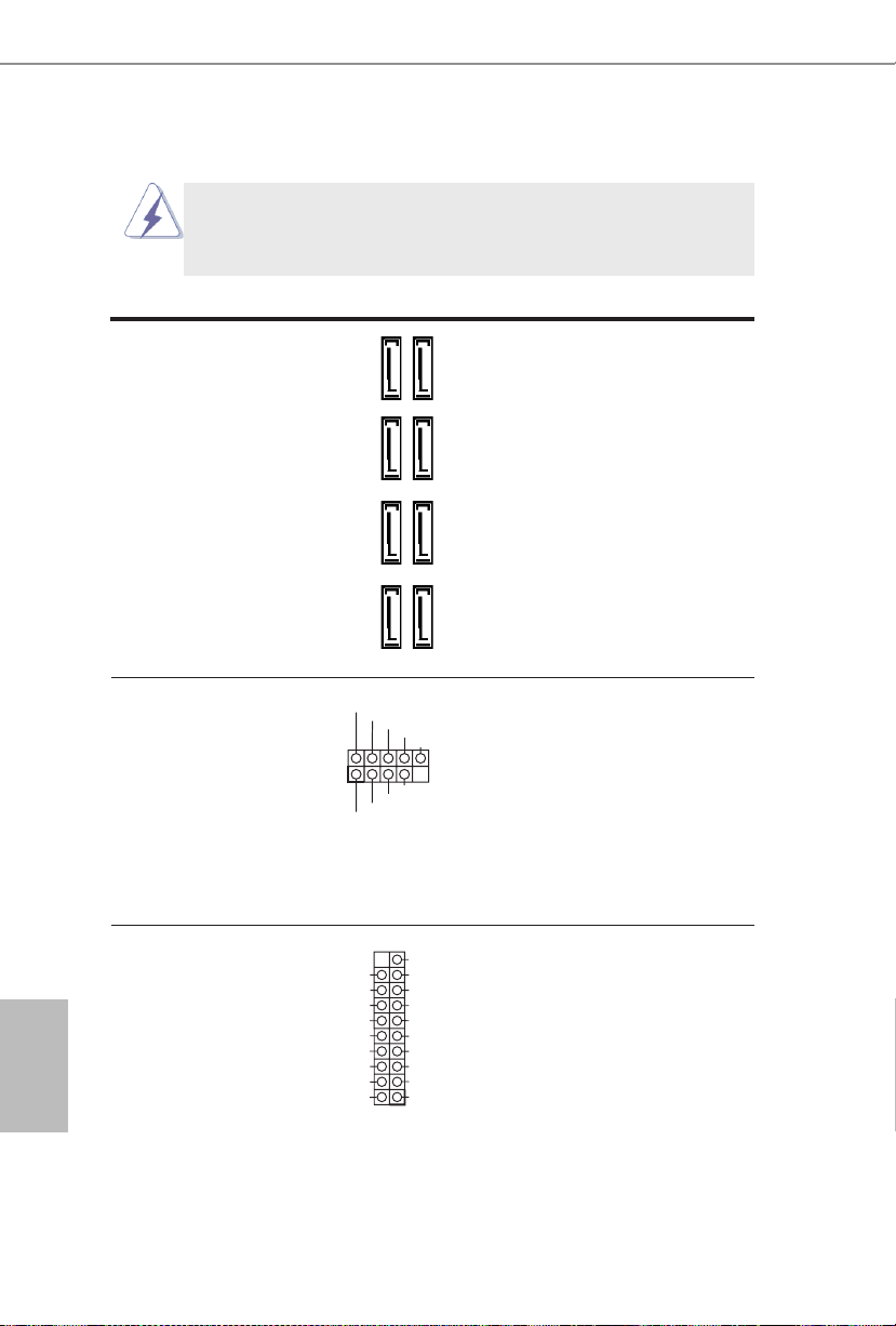
2.6 Onboard Headers and Connectors
DUMMY
GND
GND
P+
P-
USB_PWR
P+
P-
USB_PWR
1
Onboard headers and connectors are NOT jumpers. Do NOT place
jumper caps over these headers and connectors. Placing jumper caps
over the headers and connectors will cause permanent damage of the
motherboard!
Serial ATA3 Connectors These eight Serial ATA3
(SATA_1_2: see p.1, No. 12)
(SATA_3_4: see p.1, No. 11)
(SATA_5_6: see p.1, No. 10)
(SATA_7_8: see p.1, No. 9)
6.0 Gb/s data transfer rate.
USB 2.0 Headers Besides four default USB 2.0
(9-pin USB6_7)
(see p.1 No. 19)
(9-pin USB8_9)
(see p.1 No. 18)
ports on the I/O panel, there
are two USB 2.0 headers on
this motherboard. Each USB 2.0
header can support two USB
2.0 ports.
(SATA3) connectors support
SATA data cables for internal
storage devices. The current
SATA3 interface allows up to
SATA_5_6 SATA_7_8SATA_3_4SATA_1_2
USB 3.0 Header Besides two default USB 3.0
(19-pin USB3_2_3)
(see p.1 No. 7)
ports on the I/O panel, there is
one USB 3.0 header on this
motherboard. This USB 3.0
header can support two USB 3.0
ports.
Vbus
IntA_PA_SSRX-
IntA_PA_SSRX+
GND
IntA_PA_SSTX-
IntA_PA_SSTX+
GND
IntA_PA_D-
IntA_PA_D+
VbusVbus
IntA_PB_SSRX-
IntA_PB_SSRX+
GND
IntA_PB_SSTX-
IntA_PB_SSTX+
GND
IntA_PB_D-
IntA_PB_D+
Dummy
1
17
Page 19

English
Front Panel Audio Header This is an interface for the front
J_SENSE
OUT2_L
1
MIC_RET
PRESENCE#
GND
OUT2_R
MIC2_R
MIC2_L
OUT_RET
GND
RESET#
PWRBTN#
PLED-
PLED+
GND
HDLED-
HDLED+
1
GND
(9-pin HD_AUDIO1)
(see p.1 No. 21)
panel audio cable that allows
convenient connection and
control of audio devices.
1. High Denition Audio supports Jack Sensing, but the panel wire on
the chassis must support HDA to function correctly. Please follow the
instruction in our manual and chassis manual to install your system.
2. If you use AC’97 audio panel, please install it to the front panel audio
header as below:
A. Connect Mic_IN (MIC) to MIC2_L.
B. Connect Audio_R (RIN) to OUT2_R and Audio_L (LIN) to OUT2_L.
C. Connect Ground (GND) to Ground (GND).
D. MIC_RET and OUT_RET are for HD audio panel only. You don’t
need to connect them for AC’97 audio panel.
E. To activate the front mic.
For Windows® 8.1 / 8.1 64-bit / 8 / 8 64-bit / 7 / 7 64-bit OS:
Go to the “FrontMic” Tab in the Realtek Control panel. Adjust
“Recording Volume”.
System Panel Header This header accommodates
(9-pin PANEL1)
(see p.1 No. 13)
several system front panel
functions.
18
Connect the power switch, reset switch and system status indicator
on the chassis to this header according to the pin assignments below.
Note the positive and negative pins before connecting the cables.
PWRBTN (Power Switch):
Connect to the power switch on the chassis front panel. You may con-
gure the way to turn off your system using the power switch.
RESET (Reset Switch):
Connect to the reset switch on the chassis front panel. Press the reset
switch to restart the computer if the computer freezes and fails to perform a normal restart.
Page 20

English
FM2A88X Pro3+
1
+5V
DUMMY
DUMMY
SPEAKER
GND
_
1
PLED+
PLED+
PLED-
PLED (System Power LED):
Connect to the power status indicator on the chassis front panel. The
LED is on when the system is operating. The LED keeps blinking
when the sys-tem is in S1 sleep state. The LED is off when the system
is in S3/S4 sleep state or powered off (S5).
HDLED (Hard Drive Activity LED):
Connect to the hard drive activity LED on the chassis front panel. The
LED is on when the hard drive is reading or writing data.
The front panel design may differ by chassis. A front panel module
mainly consists of power switch, reset switch, power LED, hard drive
activity LED, speaker and etc. When connecting your chassis front
panel module to this header, make sure the wire assignments and the
pin assign-ments are matched correctly.
Chassis Speaker Header Please connect the chassis
(4-pin SPEAKER 1)
(see p.1 No. 17)
speaker to this header.
Power LED Header Please connect the chassis
(3-pin PLED1)
(see p.1 No. 16)
power LED to this header to
indicate system power status.
The LED is on when the system
is operating. The LED keeps
blinking in S1 state. The LED is
off in S3/S4 state or S5 state
(power off).
Chassis and Power Fan Please connect the fan cable
Connectors to the fan connector and
(4-pin CHA_FAN1)
(see p.1 No. 23)
match the black wire to the
ground pin.
FAN_SPEED_CONTROL
CHA_FAN_SPEED
+12V
(3-pin CHA_FAN2)
(see p.1 No. 8)
(3-pin CHA_FAN3)
(see p.1 No. 15)
GND
FAN_VOLTAGE
CHA
FAN_SPEED
19
Page 21

English
(3-pin PWR_FAN1)
CPU_
N_SPEED_CONTROL
GND
(see p.1 No. 22)
CPU Fan Connector Please connect the CPU fan
(4-pin CPU_FAN1)
(see p.1 No. 2)
cable to the connector and
match the black wire to the
ground pin.
(3- pin CPU_FAN2)
(see p .1, No. 3)
FA
FAN_SPEED
+12V
GND
1 2 3 4
FAN_VOLTAGE
CPU_FAN_SPEED
Though this motherboard provides 4-Pin CPU fan (Quiet Fan) support, the 3-Pin
CPU fan still can work successfully even without the fan speed control function.
If you plan to connect the 3-Pin CPU fan to the CPU fan connector on this
motherboard, please connect it to Pin 1-3.
Pin 1-3 Connected
3-Pin Fan Installation
ATX Power Connector Please connect an ATX power
(24-pin ATXPWR1)
(see p.1 No. 6)
supply to this connector.
12
24
1
13
Though this motherboard provides 24-pin ATX power connector,
it can still work if you adopt a traditional 20-pin ATX power supply.
To use the 20-pin ATX power supply, please plug your power
supply along with Pin 1 and Pin 13.
20-Pin ATX Power Supply Installation
20
12
1
24
13
Page 22

English
FM2A88X Pro3+
CCTS#1
RRTS#1
DDSR#1
DDTR#1
RRXD1
GND
TTXD1
DDCD#1
1
RRI#1
ATX 12V Power Connector Please connect an ATX 12V
(8-pin ATX12V1)
(see p.1 No. 1)
power supply to this connector.
Though this motherboard provides 8-pin ATX 12V power connector, it can still work
if you adopt a traditional 4-pin ATX 12V power supply. To use the
8 5
4-pin ATX power supply, please plug your power supply along with
Pin 1 and Pin 5.
PCIe Power Connector
(4-pin PCIE_PWR1)
(see p.1, No. 24)
4-Pin ATX 12V Power Supply Installation
Please connect a 4 pin molex
power cable to this connector
when more than three
4 1
graphics cards are installed.
Serial port Header This COM1 header supports a
(9-pin COM1)
(see p.1 No. 20)
serial port module.
21
Page 23

Deutsch
1. Einführung
Wir danken Ihnen für den Kauf des ASRock FM2A88X Pro3+ Motherboard, ein zuverlässiges Produkt, welches unter den ständigen, strengen Qualitätskontrollen von
ASRock gefertigt wurde. Es bietet Ihnen exzellente Leistung und robustes Design,
gemäß der Verpflichtung von ASRock zu Qualität und Halbarkeit. Diese Schnellinstallationsanleitung führt in das Motherboard und die schrittweise Installation
ein. Details über das Motherboard nden Sie in der Bedienungsanleitung auf der
Support-CD.
Da sich Motherboard-Spezikationen und BIOS-Software verändern
können, kann der Inhalt dieses Handbuches ebenfalls jederzeit geändert
werden. Für den Fall, dass sich Änderungen an diesem Handbuch
ergeben, wird eine neue Version auf der ASRock-Website, ohne weitere
Ankündigung, verfügbar sein. Die neuesten Grakkarten und unterstützten
CPUs sind auch auf der ASRock-Website aufgelistet.
ASRock-Website: http://www.asrock.com
Wenn Sie technische Unterstützung zu Ihrem Motherboard oder spezische
Informationen zu Ihrem Modell benötigen, besuchen Sie bitte unsere
Webseite:
www.asrock.com/support/index.asp
1.1 Kartoninhalt
ASRock FM2A88X Pro3+ Motherboard (ATX-Formfaktor)
ASRock FM2A88X Pro3+ Schnellinstallationsanleitung
ASRock FM2A88X Pro3+ Support-CD
Zwei Serial ATA (SATA) -Datenkabel (optional)
Ein I/O Shield
22
Page 24

Deutsch
FM2A88X Pro3+
1.2 Spezikationen
Platform
CPU
Chipsatz
Speicher
Erweiterungssteckplätze
• ATX-Formfaktor
• Alle Feste Kondensatordesign
• PCB mit hochverdichtetem Glasfasergewebe
• Unterstützt Prozessoren für Sockel FM2+ (95 W) / FM2
(100 W)
• AMD A88X (Bolton-D4)
• 4 + 2-Stromphasendesign
• Unterstützung von Dual-Kanal-Speichertechnologie
• 4 x Steckplätze für DDR3
• Unterstützt DDR3 2400+(OC)/2133/1866/1600/1333/
1066 non-ECC, ungepufferter Speicher
• Max. Kapazität des Systemspeichers: 64GB
• Unterstützt Intel® Extreme Memory Prole (XMP)1.3/1.2
• Unterstützt AMDs Memory Prole Technology (AMP)
bis AMP 2400
• 1 x PCI Express 3.0 x16-Steckplätze (PCIE4: x16Modus)
* PCIE 3.0 wird nur mit FM2+-Prozessor unterstützt.FM2Prozessor unterstützt nur PCIE 2.0.
• 1 x PCI Express 2.0 x16-Steckplatz (PCIE5: x4-Modus)
• 3 x PCI Express 2.0 x1-Steckplätze
• 2 x PCI -Steckplätze
• Unterstützt AMD Quad CrossFireXTM, CrossFireXTM und
duale Gra kkarten
OnboardVGA
• Integrierte Grakkarte der AMD Radeon
in APU der A-Serie
• DirectX 11.1, Pixel Shader 5.0 mit FM2+-Prozessor.
DirectX 11, Pixel Shader 5.0 mit FM2-Prozessor.
• Maximal gemeinsam genutzter Speicher 2GB
• Doppel-VGA Ausgabe: unterstützt DVI-D und
D-Sub Ports durch unabhängige Bildschirmanzeige
Kontrolleure
TM
R7/R5-Serie
23
Page 25

Deutsch
• Unterstützt Dual-link DVI-D mit einer maximalen
Auösung von 2560 x 1600 bei 60 Hz
• Unterstützt D-Sub mit einer maximalen Auösung von
1920 x 1200 bei 60 Hz
• Unterstützt AMD Steady VideoTM 2.0: Neuartige
Funktion der Videonachbearbeitung für automatische
Reduzierung von Bildschwankungen bei Heim-/OnlineVideos
• Unterstützt HDCP-Funktion mit DVI-D-Port
• Unterstutzt 1080p Blu-ray (BD) / HD-DVD-Wiedergabe
mit DVI-D-Port
Audio
LAN
E/A-Anschlüsse
an der
Rückseite
• 5.1 CH HD Audio (Realtek ALC662 Audio Codec)
• Unterstützt Überspannungsschutz (ASRocks
Komplettschutz vor Spannungsspitzen)
• PCIE x1 Gigabit LAN 10/100/1000 Mb/s
• Realtek R T L 8111G R
• Unterstützt Wake-On-WAN
• Unterstützt Wake-On-LAN
• Unterstützt Schutz vor Blitzschlag/elektrostatischer Ent-
ladung (ASRocks Komplettschutz vor Spannungsspitzen)
• Unterstützt LAN-Kabelerkennung
• Unterstützt energieef zientes Ethernet 802.3az
• Unterstützt PXE
• 1 x PS/2-Mausanschluss
• 1 x PS/2-Tastaturanschluss
• 1 x D-Sub port
• 1 x DVI-D port
• 4 x Standard-USB 2.0-Anschlüsse (Unterstützt
Schutz vor elektrostatischer Entladung (ASRocks
Komplettschutz vor Spannungsspitzen))
• 2 x Standard-USB 3.0-Anschlüsse (AMD A88X
(Bolton-D4)) (Unterstützt Schutz vor elektrostatischer
Entladung (ASRocks Komplettschutz vor
Spannungsspitzen))
24
Page 26

Deutsch
FM2A88X Pro3+
• 1 x RJ-45 LAN Port mit LED (ACT/LINK LED und
SPEED LED)
• HD Audiobuchse: Audioeingang / Lautsprecher vorne /
Mikrofon
Speicher
Anschlüsse
BIOS
• 8 x SATA 3-Anschluss mit 6,0 Gb/s, unterstützt RAID(RAID 0, RAID 1, RAID 5 und RAID 10), NCQ-, AHCIund „Hot Plugging“-Funktionen
• 1 x COM-Anschluss-Header
• 1 x Betriebs-LED-Header
• 2 x CPUlüfter-Anschluss (1 x 4-pin, 1 x 3-pin)
• 3 x Gehäuselüfter-Anschluss (1 x 4-pin, 2 x 3-pin)
• 1 x Stromlüfter-Anschluss (3-pin)
• 1 x 24-pin ATX-Netz-Header
• 1 x 8-pin anschluss für 12V-ATX-Netzteil
• 1 x 1 PCIe-Stromanschluss
• 1 x Anschluss für Audio auf der Gehäusevorderseite
• 2 x USB 2.0-Anschlüsse (Unterstützung 4 zusätzlicher
USB 2.0-Anschlüsse) (Unterstützt Schutz vor elektrostatischer Entladung (ASRocks Komplettschutz vor
Spannungsspitzen))
• 1 x En-tête USB 3.0 de AMD A88X (Bolton-D4) (prendre
en charge 2 ports USB 3.0 supplémentaires) (Unterstützt
Schutz vor elektrostatischer Entladung (ASRocks
Komplettschutz vor Spannungsspitzen))
• 64Mb AMIs Legal BIOS UEFI mit GUI-Unterstützung
• Unterstützung für “Plug and Play”
• ACPI 1.1-Weckfunktionen
• JumperFree-Modus
• SMBIOS 2.3.1
• DRAM, VDDP, VDDR Stromspannung Multianpassung
Hardware
Monitor
• CPU-Temperatursensor
• Motherboardtemperaturerkennung
• Drehzahlmessung für CPUlüfter
• Drehzahlmessung für Gehäuselüfter
• Geräuscharmer CPU-/Gehäuselüfter
25
Page 27

Deutsch
• Mehrstu ge Geschwindigkeitsteuerung für CPU-/
• Gehäuselüfter Spannungsüberwachung: +12V, +5V,
+3.3V, Vcor e
Betriebssysteme
Zertizierungen
* Für die ausführliche Produktinformation, besuchen Sie bitte unsere Website:
http://www.asrock.com
• Microsoft® Windows® 8.1 32-bit / 8.1 64-bit / 8 32-bit /
8 64-bit / 7 32-bit / 7 64-bit
• FCC, CE, WHQL
• Prêt pour ErP/EuP (alimentation Prêt pour ErP/EuP
requise)
26
Page 28
Deutsch
FM2A88X Pro3+
1.3 Einstellung der Jumper
Die Abbildung verdeutlicht, wie Jumper
gesetzt werden. Werden Pins durch
Jumperkappen verdeckt, ist der Jumper
“Gebrückt”. Werden keine Pins durch
Jumperkappen verdeckt, ist der Jumper
“Offen”. Die Abbildung zeigt einen 3-Pin
Jumper dessen Pin1 und Pin2 “Ge-
brückt” sind, bzw. es bendet sich eine
Jumper-Kappe auf diesen beiden Pins.
Jumper Einstellun Beschreibung
CMOS löschen
(CLRCMOS1, 3-Pin jumper)
(siehe S.1, No. 14)
Hinweis:
CLRCMOS1 ermöglicht Ihnen die Löschung der Daten im CMOS. Zum
Löschen und Zurücksetzen der Systemparameter auf die Standardeinrichtung
schalten Sie den Computer bitte aus und trennen das Netzkabel von der
Stromversorgung. Warten Sie 15 Sekunden, schließen Sie dann Pin2 und
Pin3 am CLRCMOS1 über einen Jumper fünf Sekunden lang kurz. Sie
sollten das CMOS allerdings nicht direkt nach der BIOS-Aktualisierung
löschen. Wenn Sie das CMOS nach Abschluss der BIOS-Aktualisierung
löschen müssen, fahren Sie zuerst das System hoch. Fahren Sie es dann
vor der CMOS-Löschung herunter. Bitte beachten Sie, dass Kennwort,
Datum, Uhrzeit, benutzerdeniertes Prol, 1394 GUID und MAC-Adresse
nur gelöscht werden, wenn die CMOS-Batterie entfernt wird.
DefaultEinstellung
CMOS
löschen
27
Page 29
Deutsch
1.4 Anschlüsse
DUMMY
GND
GND
P+
P-
USB_PWR
P+
P-
USB_PWR
1
Anschlussleisten sind KEINE Jumper. Setzen Sie KEINE Jumperkappen
auf die Pins der Anschlussleisten. Wenn Sie die Jumperkappen auf die
Anschlüsse setzen, wird das Motherboard permanent beschädigt!
Anschluss Beschreibung
Seriell-ATA3-Anschlüsse Diese acht Serial ATA3-
(SATA_1_2: siehe S.1 - No. 12)
(SATA_3_4: siehe S.1 - No. 11)
(SATA_5_6: siehe S.1 - No. 10)
(SATA_7_8: siehe S.1 - No. 9)
aktuelle SATA3- Schnittstelle
ermöglicht eine
Datenübertragungsrate bis
6,0 Gb/s.
USB 2.0-Header Zusätzlich zu den vier
(9-pol. USB6_7)
(siehe S.1 - No. 19)
(9-pol. USB8_9)
(siehe S.1 - No. 18)
üblichen USB 2.0-Ports an den
I/O-Anschlüssen benden sich
zwei USB 2.0-
Anschlussleisten am
Motherboard. Pro USB 2.0-
Anschlussleiste werden zwei
USB 2.0-Ports unterstützt.
(SATA3-)Verbínder
unterstützten SATA-Datenkabel
für interne
Massenspeichergeräte. Die
SATA_5_6 SATA_7_8SATA_3_4SATA_1_2
28
USB 3.0-Header Neben zwei Standard-USB
(19-pol. USB3_2_3)
(siehe S.1 - No. 7)
Header an diesem
Motherboard. Dieser USB 3.0 Header kann zwei USB 3.0-
3.0-Ports am E/A-Panel
bendet sich ein USB 3.0-
IntA_PA_SSRX-
IntA_PA_SSRX+
IntA_PA_SSTX-
IntA_PA_SSTX+
IntA_PA_D-
IntA_PA_D+
Ports unterstützen.
Vbus
GND
GND
VbusVbus
IntA_PB_SSRX-
IntA_PB_SSRX+
GND
IntA_PB_SSTX-
IntA_PB_SSTX+
GND
IntA_PB_D-
IntA_PB_D+
Dummy
1
Page 30
Deutsch
FM2A88X Pro3+
Anschluss für Audio auf Dieses Interface zu einem
J_SENSE
OUT2_L
1
MIC_RET
PRESENCE#
GND
OUT2_R
MIC2_R
MIC2_L
OUT_RET
GND
RESET#
PWRBTN#
PLED-
PLED+
GND
HDLED-
HDLED+
1
GND
der Gehäusevorderseite Audio-Panel auf der Vorder
(9-Pin HD_AUDIO1)
(siehe S.1 - No. 21)
Anschlussmöglichkeit und
seite Ihres Gehäuses,
ermöglicht Ihnen eine bequeme
Kontrolle über Audio-Geräte.
1. High Denition Audio unterstützt Jack Sensing (automatische Erkennung
falsch angeschlossener Geräte), wobei jedoch die Bildschirmverdrahtung
am Gehäuse HDA unterstützen muss, um richtig zu funktionieren.
Beachten Sie bei der Installation im System die Anweisungen in unserem
Handbuch und im Gehäusehandbuch.
2. Wenn Sie die AC’97-Audioleiste verwenden, installieren Sie diese wie
nachstehend beschrieben an der Front-Audioanschlussleiste:
A. Schließen Sie Mic_IN (MIC) an MIC2_L an.
B. Schließen Sie Audio_R (RIN) an OUT2_R und Audio_L (LIN) an OUT2_L an.
C. Schließen Sie Ground (GND) an Ground (GND) an.
D. MIC_RET und OUT_RET sind nur für den HD-Audioanschluss gedacht. Diese
Anschlüsse müssen nicht an die AC’97-Audioleiste angeschlossen werden.
E. So aktivieren Sie das Mikrofon an der Vorderseite.
Bei den Betriebssystemen Windows® 8.1 / 8.1 64 Bit / 8 / 8 64 Bit / 7 / 7 64
Bit: Wählen Sie im Realtek-Bedienfeld die „FrontMic“ (Vorderes
Mikrofon)-Registerkarte. Passen Sie die „Recording Volume“ (Aufnahmelaut
stärke) an.
System Panel-Header Dieser Header unterstützt
(9-pin PANEL1)
(siehe S.1 - No. 13)
Schließen Sie die Ein-/Austaste, die Reset-Taste und die
Systemstatusanzeige am Gehäuse an diesen Header an; befolgen Sie
dabei die nachstehenden Hinweise zur Pinbelegung. Beachten Sie die
positiven und negativen Pins, bevor Sie die Kabel anschließen.
mehrere Funktion der
Systemvorderseite.
29
Page 31

Deutsch
PWRBTN (Ein-/Ausschalter):
1
+5V
DUMMY
DUMMY
SPEAKER
1
PLED+
PLED+
PLED-
Zum Anschließen des Ein-/Ausschalters an der Frontblende des Gehäu
ses. Sie können kongurieren, wie das System mit Hilfe des
Ein-/Ausschalters ausgeschaltet werden können soll.
RESET (Reset-Taste):
Zum Anschließen der Reset-Taste an der Frontblende des Gehäuses.
Mit der Reset-Taste können Sie den Computer im Falle eines Absturzes
neu starten.
PLED (Systembetriebs-LED):
Zum Anschließen der Betriebsstatusanzeige an der Frontblende des
Gehäuses. Die LED leuchtet, wenn das System in Betrieb ist. Die LED
blinkt, wenn sich das System im Ruhezustand S1 bendet. Die LED
schaltet sich aus, wenn sich das System in den Modi S3/S4 bendet
oder ausgeschaltet ist (S5).
HDLED (Festplattenaktivitäts-LED):
Zum Anschließen der Festplattenaktivitäts-LED an der Frontblende des
Gehäuses. Die LED leuchtet, wenn die Festplatte Daten liest oder
schreibt.
Das Design der Frontblende kann je nach Gehäuse variiere. Ein
Frontblendenmodul besteht hauptsächlich aus einer Ein-/Austaste, einer
Reset-Taste, einer Betriebs-LED, einer Festplattenaktivitäts-LED,
Lautsprechern, etc. Stellen Sie beim Anschließen des
Frontblendenmoduls Ihres Gehäuses an diesem Header sicher, dass die
Kabel- und Pinbelegung korrekt übereinstimmen.
30
Gehäuselautsprecher-Header Schließen Sie den
(4-pin SPEAKER1)
(siehe S.1 - No. 17)
Gehäuselautsprecher an
diesen Header an.
Betriebs-LED-Header Bitte schließen Sie die
(3-pin PLED1)
(siehe S.1 - No. 16)
Betriebs-LED des Gehäuses
zur Anzeige des
Systembetriebsstatus an
diesem Header an. Die LED
leuchtet, wenn das System in
Betrieb ist. Die LED blinkt im
S1-Zustand. Im S3-/S4- oder
S5-Zustand (ausgeschaltet)
leuchtet die LED nicht.
Page 32

Deutsch
FM2A88X Pro3+
Gehäuse- und Verbinden Sie die Lüfterkabel
GND
_
CPU_
FAN_SPEED_CONTROL
GND
Stromlüfteranschlüsse mit den Lüfteranschlüssen,
(4-pin CHA_FAN1)
(siehe S.1 - No. 23)
wobei der schwarze Draht an
den Schutzleiterstift
angeschlossenwird.
(3-pin CHA_FAN2)
(siehe S.1 - No. 8)
(3-pin CHA_FAN3)
(siehe S.1 - No. 15)
FAN_SPEED_CONTROL
CHA_FAN_SPEED
GND
FAN_VOLTAGE
CHA
FAN_SPEED
+12V
(3-pin PWR_FAN1)
(siehe S.1 - No. 22)
CPU-Lüfteranschluss Verbinden Sie das CPU -
(4-pin CPU_FAN1)
(siehe S.1 - No. 2)
schwarzen Draht dem
Lüfterkabel mit diesem
Anschluss und passen Sie den
FAN_SPEED
+12V
GND
1 2 3 4
Erdungsstift an.
Obwohl dieses Motherboard einen vierpoligen CPU-Lüfteranschluss
(Quiet Fan) bietet, können auch CPU-Lüfter mit dreipoligem Anschluss
angeschlossen werden; auch ohne Geschwindigkeitsregulierung. Wenn
Sie einen dreipoligen CPU-Lüfter an den CPU-Lüferanschluss dieses
Motherboards anschließen möchten, verbinden Sie ihn bitte mit den
Pins 1 – 3.
Lüfter mit dreipoligem Anschluss installieren
(3-pin CPU_FAN2)
(siehe S.1 - No. 3)
ATX-Netz-Header Verbinden Sie die ATX-
(24-pin ATXPWR1)
(siehe S.1 - No. 6)
FAN_VOLTAGE
12 124
Stromversorgung mit diesem
Header.
Pins 1–3 anschließen
CPU_FAN_SPEED
13
31
Page 33

Deutsch
ATX 12V Anschluss Bitte schließen Sie an diesen
CCTS#1
RRTS#1
DDSR#1
DDTR#1
RRXD1
GND
TTXD1
DDCD#1
1
RRI#1
(8-pin ATX12V1)
(siehe S.1 - No. 1)
Obwohl diese Hauptplatine 8-Pin ATX 12V Stromanschluss zur
Verfügung stellt, kann sie noch arbeiten, wenn Sie einen
traditionellen 4-Pin ATX 12V Energieversorgung adoptieren. Um die
4-Pin ATX Energieversorgung zu verwenden, stecken Sie bitte Ihre
Energieversorgung zusammen mit dem Pin 1 und Pin 5 ein.
Anschluss die ATX 12V
Stromversorgung an.
8 5
Installation der 4-Pin ATX 12V Energieversorgung
4 1
PCIe-Stromanschluss
(PCIE_PWR1, vierpolig)
(siehe S.1 - No. 24)
Bitte schließen Sie
ein vierpoliges MolexStromversorgungskabel an
diesen Anschluss an, wenn
mehr als drei Grakkarten
installiert sind.
COM-Anschluss-Header Dieser COM-Anschluss-
(9-pin COM1)
(siehe S.1 - No. 20)
Header wird verwendet, um
ein COM-Anschlussmodul zu
unterstützen.
3232
Page 34

Français
FM2A88X Pro3+
FM2A88X Pro3+
1. Introduction
Merci pour votre achat d’une carte mère ASRock FM2A88X Pro3+, une carte mère
très able produite selon les critères de qualité rigoureux de ASRock. Elle offre des
performances excellentes et une conception robuste conformément à l’engagement
d’ASRock sur la qualité et la abilité au long terme.
Ce Guide d’installation rapide présente la carte mère et constitue un guide
d’installation pas à pas. Des informations plus détaillées concernant la carte
mère pourront être trouvées dans le manuel l’utilisateur qui se trouve sur le CD
d’assistance.
Les spécications de la carte mère et le BIOS ayant pu être mis à
jour, le contenu de ce manuel est sujet à des changements sans
notication. Au cas où n’importe qu’elle modication intervenait sur ce
manuel, la version mise à jour serait disponible sur le site web
ASRock sans nouvel avis. Vous trouverez les listes de prise en
charge des cartes VGA et CPU également sur le site Web ASRock.
Site web ASRock, http://www.asrock.com
Si vous avez besoin de support technique en relation avec cette carte
mère, veuillez consulter notre site Web pour de plus amples
informations particulières au modèle que vous utilisez.
www.asrock.com/support/index.asp
1.1 Contenu du paquet
Carte mère ASRock FM2A88X Pro3+ (Facteur de forme ATX)
Guide d’installation rapide ASRock FM2A88X Pro3+
CD de soutien ASRock FM2A88X Pro3+
Deux câbles de données de série ATA (SATA) (en option)
Un I/O Panel Shield
33
33
Page 35

Français
1.2 Spécications
Format
CPU
Chipsets
Mémoire
Slot
d’extension
• Facteur de forme ATX
• Accessoires de Carte mère
• PCB High Density Glass Fabric
• Prend en charge les processeurs à socket FM2+
95W / FM2 100W
• Conception 4 + 2 Power Phase
• AMD A88X (Bolton-D4)
• Compatible avec la Technologie de Mémoire à Canal
Double
• 4 x slots DIMM DDR3
• Supporter DDR3 2400+(OC)/2133/1866/1600/1333/
1066 non-ECC, sans amortissement mémoire
• Capacité maxi de mémoire système: 64GB
• Prend en charge le pro l de mémoire extrême Intel®
(XMP)1.3/1.2
• Prend en charge la technologie AMD Memory Prole
(Prol de mémoire AMD - AMP) jusqu’à AMP 2400
• 1 x slots PCI Express 3.0 x16 (PCIE4 à mode x16)
* PCIE 3.0 est uniquement pris en charge le
processeur FM2+. Avec le processeur FM2, seul
PCIE 2.0 est pris en charge.
• 1 x slot PCI Express 2.0 x16 (PCIE5 à mode x4)
• 3 x slots PCI Express 2.0 x1
• 2 x slots PCI
• Support de AMD Quad CrossFireXTM, CrossFireXTM
et Dual Graphics
34
VGA sur
carte
• APU AMD Radeon
• DirectX 11.1, Pixel Shader 5.0 avec processeur
FM2+.DirectX 11, Pixel Shader 5.0 avec processeur
FM2.
TM
R7/R5 série graphiques A-series
Page 36

Français
FM2A88X Pro3+
• mémoire partagée max 2GB
• Output de VGA Duel: supporter DVI-D et D-Sub ports
par les controleurs de display independents
• Prend en charge le Dual-link DVI-D avec une
résolution maximale jusqu’à 2560x1600 @ 60Hz
• Prend en charge le D-Sub avec une résolution
maximale jusqu’à 1920x1600 @ 60Hz
• Supporte AMD Steady VideoTM 2.0: Nouvelle
fonctionnalité de traitement post-vidéo pour réduction
automatique des tremblements dans les clips vidéo
en ligne/maison
• Prise en charge de la fonction HDCP avec ports
DVI-D
• Supporter 1080p Blu-ray(BD)/ lecteur de HD-DVD
avec ports DVI-D
Audio
LAN
Panneau
arrière
• 5,1 CH HD Audio (Realtek ALC662 Audio Codec)
• Supporte la protection contre les surtensions
(protection complète contre surges ASRock)
• PCIE x1 Gigabit LAN 10/100/1000 Mb/s
• Realtek R T L 8111G R
• Supporte du Wake-On-WAN
• Supporte du Wake-On-LAN
• Supporte la protection contre la foudre/ESD (protec-
tion complète contre surges ASRock)
• Prise en charge de la détection de câble LAN
• Prend en charge la norme Energy Ef cient Ethernet
(Ethernet à ef cacité énergétique) 802.3az
• Supporte PXE
• 1 x port souris PS/2
• 1 x port clavier PS/2
• 1 x port D-Sub
• 1 x port DVI-D
• 4 x ports USB 2.0 par défaut (Supporte la protection
ESD (protection complète contre surges ASRock))
35
Page 37

Français
• 2 x ports USB 3.0 par défaut (AMD A88X
(Bolton-D4)) (Supporte la protection ESD (protection
complète contre surges ASRock))
• 1 x port LAN RJ-45 avec LED (ACT/LED
CLIGNOTANTE et LED VITESSE)
• Prise HD Audio: Entrée Ligne / Haut-parleur frontal
/Microphone
Stockage
Connecteurs
BIOS
• 8 x connecteurs 6,0 Gb/s SATA3, prise en charge
desfonctions RAID (RAID 0, RAID 1, RAID 5 et
RAID 10), NCQ, AHCI et « Connexion à chaud »
• 1 x En-tête de port COM
• 1 x LED di accensione
• 2 x Connecteur pour ventilateur de CPU (1 x br. 4, 1
x br. 3)
• 3 x Connecteur pour ventilateur de Châssis (1 x br. 4,
2 x br. 3)
• 1 x Connecteur pour ventilateur de pouvoir (br. 3)
• 1 x br. 24 connecteur d’alimentation ATX
• 1 x br. 8 connecteur d’alimentation 12V ATX
• 1 connecteur d’alimentation PCIe
• 1 x Connecteur audio panneau avant
• 2 x En-tête USB 2.0 (prendre en charge 4 ports
USB 2.0 supplémentaires) (Supporte la protection
ESD (protection complète contre surges ASRock))
• 1 x En-tête USB 3.0 de AMD A88X (Bolton-D4)
(prendre en charge 2 ports USB 3.0 supplémentaires) supplémentaires) (Supporte la protection
ESD (protection complète contre surges ASRock))
• 64Mb AMI UEFI Legal BIOS avec support GUI
• Support du “Plug and Play”
• Compatible pour événements de réveil ACPI 1.1
• Gestion jumperless
• Support SMBIOS 2.3.1
• DRAM, VDDP, VDDR Tension Multi-ajustement
36
Page 38

Français
FM2A88X Pro3+
Surveillance
système
• Détection de la température de l’UC
• Mesure de température de la carte mère
• Tachéomètre ventilateur CPU Ventilateur
• Tachéomètre ventilateur Châssis Ventilateur
• Ventilateur silencieux pour unité CPU/boîtier
• Commande de ventilateur CPU/boîtier à plusieurs
vitesses
• Monitoring de la tension: +12V, +5V, +3.3V, Vcore
OS
Certications
* Pour de plus amples informations sur les produits, s’il vous plaît visitez notre site web:
http://www.asrock.com
• Microsoft® Windows® 8.1 32-bit / 8.1 64-bit / 8 32-bit
/ 8 64-bit / 7 32-bit / 7 64-bit
• FCC, CE, WHQL
• Prêt pour ErP/EuP (alimentation Prêt pour ErP/EuP
requise)
37
Page 39

Français
1.3 Réglage des cavaliers
L’illustration explique le réglage des cavaliers. Quand un capuchon est placé sur les
broches, le cavalier est « FERME ». Si aucun capuchon ne relie les broches,le cavalier est « OUVERT ». L’illustration montre un
cavalier à 3 broches dont les broches 1 et 2
sont « FERMEES » quand le capuchon est
placé sur ces 2 broches.
Le cavalier Description
Effacer la CMOS
(CLRCMOS1)
(voir p.1 g. 14)
Remarque :
Paramètres
par défaut
CLRCMOS1 vous permet d’effacer les données du CMOS. Pour effacer
et réinitialiser les paramètres du système à la conguration originale,
veuillez éteindre l’ordinateur et débrancher le cordon d’alimentation de
la prise de courant. Après 15 secondes, utilisez un couvercle de jumper
pour court-circuiter les broches pin2 et pin3 de CLRCMOS1 pendant
secondes. Veuillez cependant ne pas effacer le CMOS immédiatement
a
près avoir mis à jour le BIOS. Si vous avez besoin d’effacer le CMOS
après avoir mis à jour le BIOS, vous devez allumer en premier le
système, puis l’éteindre avant de continuer avec l’opération d’effacement
du CMOS. Veuillez noter que le mot de passe, la date, l’heure, le prol
par défaut de l’utilisateur, 1394 GUID et l’adresse MAC seront effacés
seulement si la batterie du CMOS est enlevée.
Effacer la
CMOS
5
38
Page 40

Français
FM2A88X Pro3+
1.4 En-têtes et Connecteurs sur Carte
DUMMY
GND
GND
P+
P-
USB_PWR
P+
P-
USB_PWR
1
Les en-têtes et connecteurs sur carte NE SONT PAS des cavaliers.
NE PAS placer les capuchons de cavalier sur ces en-têtes et connecteurs. Le fait de placer les capuchons de cavalier sur les entêtes et connecteurs causera à la carte mère des dommages irréversibles!
Connecteurs Série ATA3 Ces huit connecteurs Série
(SATA_1_2: voir p.1 No. 12)
(SATA_3_4: voir p.1 No. 11)
(SATA_5_6: voir p.1 No. 10)
(SATA_7_8: voir p.1 No. 9)
actuelle permet des taux
transferts de données pouvant
aller jusqu’à 6,0 Gb/s.
En-tête USB 2.0 A côté des quatre ports USB
(USB6_7 br.9)
(voir p.1 No. 19)
(USB8_9 br.9)
(voir p.1 No. 18)
2.0 par défaut sur le panneau
E/S, il y a deux embases USB
2.0 sur cette carte mère.
Chaque embase USB 2.0 peut
prendre en charge 2 ports USB
2.0.
ATA3 (SATA3) prennent en
charge les câbles SATA pour
les périphériques de stockage
internes. L’interface SATA3
SATA_5_6 SATA_7_8SATA_3_4SATA_1_2
En-tête USB 3.0 En plus des deux ports USB
(USB3_2_3 br. 19)
(voir p.1 No. 7)
3.0 par défaut sur le panneau
E/S, il y a une barrette USB 3.0
sur la carte mère. Cette barrette
USB 3.0 peut prendre en
charge deux ports USB 3.0.
Vbus
IntA_PA_SSRX-
IntA_PA_SSRX+
IntA_PA_SSTX-
IntA_PA_SSTX+
IntA_PA_D-
IntA_PA_D+
GND
GND
VbusVbus
IntA_PB_SSRX-
IntA_PB_SSRX+
GND
IntA_PB_SSTX-
IntA_PB_SSTX+
GND
IntA_PB_D-
IntA_PB_D+
Dummy
1
39
Page 41

Français
Connecteur audio panneau C’est une interface pour
J_SENSE
OUT2_L
1
MIC_RET
PRESENCE#
GND
OUT2_R
MIC2_R
MIC2_L
OUT_RET
GND
RESET#
PWRBTN#
PLED-
PLED+
GND
HDLED-
HDLED+
1
GND
(HD_AUDIO1 br. 9)
(voir p.1 No. 21)
un câble avant audio en façade
qui permet le branchement et
le contrôle commodes de
périphériques audio.
1. L’audio à haute dénition (HDA) prend en charge la détection de che,
mais le l de panneau sur le châssis doit prendre en charge le HDA pour
fonctionner correctement. Veuillez suivre les instructions dans notre
manuel et le manuel de châssis an installer votre système.
2. Si vous utilisez le panneau audio AC’97, installez-le sur l’adaptateur audio
du panneau avant conformément à la procédure ci-dessous :
A. Connectez Mic_IN (MIC) à MIC2_L.
B. Connectez Audio_R (RIN) à OUT2_R et Audio_L (LIN) à OUT2_L.
C. Connectez Ground (GND) à Ground (GND).
D. MIC_RET et OUT_RET sont réservés au panneau audio HD. Vous
n’avez pas besoin de les connecter pour le panneau audio AC’97.
E. Pour activer le micro avant.
Pour les systèmes d’exploitation Windows® 8.1 / 8.1 64 bits / 8 / 8 64 bits / 7 /
7 64 bits : Allez sur l’onglet “FrontMic” (Micro avant) sur le
Panneau de contrôle Realtek. Ajustez “Recording Volume” (Volume
d’enregistrement).
En-tête du panneau système Cet en-tête permet d’utiliser
(PANEL1 br.9)
(voir p.1 No. 13)
plusieurs fonctions du
panneau système frontal.
Connectez l’interrupteur d’alimentation, l’interrupteur de réinitialisation et
l’indicateur d’état du système du châssis sur cette barrette en respectant
l’affectation des broches décrite ci-dessous. Faites attention aux broches
positives et négatives avant de connecter les câbles.
PWRBTN (Interrupteur d’alimentation):
Connectez ici le connecteur d’alimentation sur le panneau avant du
châssis. Vous pouvez congurer la façon de mettre votre système hors
tension avec l’interrupteur d’alimentation.
40
Page 42

Français
FM2A88X Pro3+
RESET (Interrupteur de réinitialisation):
1
+5V
DUMMY
DUMMY
SPEAKER
1
PLED+
PLED+
PLED-
GND
Connectez ici le connecteur de réinitialisation sur le panneau avant du
châssis. Appuyez sur l’interrupteur de réinitialisation pour redémarrer
l’ordinateur s’il se bloque ou s’il n’arrive pas à redémarrer normalement.
PLED (DEL alimentation système):
Connectez ici l’indicateur d’état de l’alimentation sur le panneau avant
du châssis. Ce voyant DEL est allumé lorsque le système est en
marche. Le voyant DEL clignote lorsque le système est en mode veille
S1. Le voyant DEL est éteint lorsque le système est en mode veille S3/
S4 ou lorsqu’il est éteint (S5).
HDLED (DEL activité du disque dur):
Connectez ici le voyant DEL d’activité du disque dur sur le panneau
avant du châssis. Ce voyant DEL est allumé lorsque le disque dur est en
train de lire ou d’écrire des données.
Le design du panneau avant peut varier en fonction du châssis. Un
module de panneau avant consiste principalement en : interrupteur
d’alimentation, interrupteur de réinitialisation, voyant DEL d’alimentation,
voyant DEL d’activité du disque dur, haut-parleur, etc. Lorsque vous
connectez le panneau avant de votre châssis sur cette barrette, vériez
bien à faire correspondre les ls et les broches.
En-tête du haut-parleur Veuillez connecter le
de châssis haut-parleur de châssis sur
(SPEAKER1 br. 4)
(voir p.1 No. 17)
cet en-tête.
LED di accensione Collegare il LED di accensione
(3-pin PLED1)
(vedi p.1 Nr. 16)
chassi per indicare lo stato di
alimentazione del sistema. Il
LED è acceso quando il sistema
è in funzione. Il LED continua a
lampeggiare in stato S1. Il LED
è spento in stato S3/S4 o S5
(spegnimento).
Connecteur pour châssis
et ventilateur
(CHA_FAN1 br. 4)
(voir p.1 No. 23)
FAN_SPEED_CONTROL
CHA_FAN_SPEED
+12V
Branchez les câbles du
ventilateur aux connecteurs pour
ventilateur et faites correspondre
le l noir à la broche de terre.
41
Page 43

Français
(CHA_FAN2 br. 3)
_
CPU_
FAN_SPEED_CONTROL
GND
(voir p.1 No. 8)
(CHA_FAN3 br. 3)
(voir p.1 No. 15)
GND
FAN_VOLTAGE
CHA
FAN_SPEED
(PWR_FAN1 br. 3)
(voir p.1 No. 22)
Connecteur du ventilateur Veuillez connecter le câble de
de l’UC ventilateur d’UC sur ce
(CPU_FAN1 br. 4)
(voir p.1 No. 2)
Bien que cette carte mère offre un support de (Ventilateur silencieux
ventilateur de CPU à 4 broches , le ventilateur de CPU à 3 broches peut
bien fonctionner même sans la fonction de commande de vitesse du
ventilateur. Si vous prévoyez de connecter le ventilateur de CPU à 3
broches au connecteur du ventilateur de CPU sur cette carte mère,
veuillez le connecter aux broches 1-3.
(CPU_FAN2 br. 3)
(voir p.1 No. 3)
connecteur et brancher le l
noir sur la broche de terre.
En-tête d’alimentation ATX Veuillez connecter l’unité
(ATXPWR1 br. 24)
(voir p.1 No. 6)
d’alimentation ATX sur cet en-
tête.
FAN_SPEED
+12V
GND
1 2 3 4
Installation de ventilateur à 3 broches
Broches 1-3 connectées
FAN_VOLTAGE
CPU_FAN_SPEED
12 124
13
Bien que cette carte mère fournisse un connecteur de
courant ATX 24 broches, elle peut encore fonctionner
si vous adopter une alimentation traditionnelle ATX 20
broches. Pour utiliser une alimentation ATX 20 broches,
branchez à l’alimentation électrique ainsi qu’aux
broches 1 et 13.
20-Installation de l’alimentation électrique ATX
4242
12
1
24
13
Page 44

FM2A88X Pro3+
Français
FM2A88X Pro3+
Connecteur ATX 12V Veuillez connecter une unité
CCTS#1
RRTS#1
DDSR#1
DDTR#1
RRXD1
GND
TTXD1
DDCD#1
1
RRI#1
(ATX12V1 br.8)
(voir p.1 No. 1)
Bien que cette carte mère possède 8 broches connecteur d’alimentation
ATX 12V, il peut toujours travailler si vous adoptez une approche
traditionnelle à 4 broches ATX 12V alimentation. Pour utiliser
l’alimentation des 4 broches ATX, branchez votre alimentation
avec la broche 1 et la broche 5.
d’alimentation électrique ATX
12V sur ce connecteur.
8 5
Connecteur
d'alimentation PCIe
(PCIE_PWR1 4 broches)
(voir p.1 No. 24)
4-Installation d’alimentation à 4 broches ATX 12V
Veuillez connecter un câble
d'alimentation 4 broches à
ce connecteur lorsque vous
installez plus de trois cartes
4 1
graphiques.
En-tête de port COM Cette en-tête de port COM est
(COM1 br.9)
(voir p.1 No. 20)
utilisée pour prendre en charge
un module de port COM.
43
43
Page 45

Italiano
1. Introduzione
Grazie per aver scelto una scheda madre ASRock FM2A88X Pro3+, una scheda
madre afdabile prodotta secondo i severi criteri di qualità ASRock. Le prestazioni
eccellenti e il design robusto si conformano all’impegno di ASRock nella ricerca
della qualità e della resistenza.
Questa Guida Rapida all’Installazione contiene l’introduzione alla motherboard e la
guida passo-passo all’installazione. Informazioni più dettagliate sulla motherboard si
possono trovare nel manuale per l’utente presente nel CD di supporto.
Le speciche della scheda madre e il software del BIOS possono
essere aggiornati, pertanto il contenuto di questo manuale può subire
variazioni senza preavviso. Nel caso in cui questo manuale sia
modicato, la versione aggiornata sarà disponibile sul sito di ASRock
senza altro avviso. Sul sito ASRock si possono anche trovare le più
recenti schede VGA e gli elenchi di CPU supportate.
ASRock website http://www.asrock.com
Se si necessita dell’assistenza tecnica per questa scheda madre,
visitare il nostro sito per informazioni speciche sul modello che si
sta usando.
www.asrock.com/support/index.asp
1.1 Contenuto della confezione
Scheda madre ASRock FM2A88X Pro3+ (ATX Form Factor)
Guida di installazione rapida ASRock FM2A88X Pro3+
CD di supporto ASRock FM2A88X Pro3+
Due cavi dati Serial ATA (SATA) (opzionali)
Un I/O Shield
44
44
Page 46

Italiano
FM2A88X Pro3+
FM2A88X Pro3+
1.2 Speciche
Piattaforma
Processore
Chipset
Memoria
Slot di espansione
• ATX Form Factor
• Design condensatore compatto
• Circuito in vetro ad alta densità
• Supporto per processori socket FM2+ 95W / FM2 100W
• Struttura di fase con alimentazione 4 + 2
• AMD A88X (Bolton-D4)
• Supporto tecnologia Dual Channel Memory
• 4 x slot DDR3 DIMM
• Supporto DDR3 2400+(OC)/2133/1866/1600/1333/1066
non-ECC, momoria senza buffer
• Capacità massima della memoria di sistema: 64GB
• Supporto di Intel® XMP (Extreme Memory Prole)1.3/1.2
• Supporta tecnologia AMD Memory Prole (AMP) no ad
AMP 2400
• 1 x slot PCI Express 3.0 x16 (PCIE4: modalità x16)
* PCIE 3.0 è supportato solo con CPU FM2+. Con CPU
FM2, supporta solo PCIE 2.0.
• 1 x slot PCI Express 2.0 x16 (PCIE5: modalità x4)
• 3 x slot PCI Express 2.0 x1
• 2 x slot PCI
• Supporta AMD Quad CrossFireXTM, CrossFireXTM e
Dual Graphics
VGA su
scheda
• Graca serie AMD Radeon
serie A
• DirectX 11.1, Pixel Shader 5.0 con CPU FM2+. DirectX
11, Pixel Shader 5.0 con CPU FM2.
• Memoria massima condivisa 2GB
• Uscita VGA Doppia: supporto porte DVI-D e D-Sub
tramite veri catore display indipendente
TM
R7/R5 integrata in APU
45
45
Page 47

Italiano
• Supporta Dual-link DVI-D con risoluzione massima no
a 2560x1600 @ 60Hz
• Supporta D-Sub con risoluzione massima no a
1920x1200 @ 60Hz
• Supporta AMD Steady VideoTM 2.0: Nuova capacità di
post-elab orazione video per la riduzione automatica
delle vibrazioni nei video a casa/on-line
• Supporto della funzione HDCP con le porte DVI-D
• Supporto 1080p Blu-ray (BD) / HD-DVD riproduzione
con le porte DVI-D
Audio
LAN
Pannello
posteriore I/O
• 5.1 CH HD Audio (Realtek ALC662 Audio Codec)
• Supporto protezione da sovratensione (protezione
completa ASRock dai picchi di corrente)
• PCIE x1 Gigabit LAN 10/100/1000 Mb/s
• Realtek R T L 8111G R
• Supporta Wake-On-WAN
• Supporta Wake-On-LAN
• Supporto la protezione da fulmini/scariche elettrostat-
iche (ESD) (protezione completa ASRock dai picchi di
corrente)
• Supporta il rilevamento cavo LAN
• Supporto di Energy Ef cient Ethernet 802.3az
• Supporta PXE
• 1 x porta PS/2 per mouse
• 1 x porta PS/2 per tastiera
• 1 x Porta D-Sub
• 1 x Porta DVI-D
• 4 x porte USB 2.0 già integrate (Supporto della
protezione da scariche elettrostatiche (ESD) (protezione
completa ASRock dai picchi di corrente))
• 2 x porte USB 3.0 già integrate (AMD A88X (Bolton-D4))
(Supporto della protezione da scariche elettrostatiche
(ESD) (protezione completa ASRock dai picchi di
corrente))
46
Page 48

Italiano
FM2A88X Pro3+
• 1 x porte LAN RJ-45 con LED (LED azione/
collegamento e LED velocità)
• Connettore HD Audio: ingresso linea / cassa frontale /
microfono
Archiviazione
Connettori
BIOS
• 8 x connettori SATA3 6,0 Gb/s, supporto di RAID (RAID
0, RAID 1, RAID 5 e RAID 10) e delle funzioni NCQ,
AHCI e “Hot Plug”
• 1 x collettore porta COM
• 1 x LED di accensione
• 2 x Connettore CPU ventola (1 x 4-pin, 1 x 3-pin)
• 3 x Connettore Chassis ventola (1 x 4-pin, 2 x 3-pin)
• 1 x Connettore Alimentazione ventola (3-pin)
• 1 x 24-pin collettore alimentazione ATX
• 1 x 8-pin connettore ATX 12V
• 1 x Connettore di alimentazione PCIe
• 1 x Connettore audio sul pannello frontale
• 2 x Collettore USB 2.0 (supporta 4 porte USB 2.0)
(Supporto della protezione da scariche elettrostatiche
(ESD) (protezione completa ASRock dai picchi di corrente))
• 1 x Collettore USB 3.0 di AMD A88X (Bolton-D4) (supporta 2 porte USB 3.0) (Supporto della protezione da
scariche elettrostatiche (ESD) (protezione completa
ASRock dai picchi di corrente))
• 64Mb AMI UEFI Legal BIOS con interfaccia di supporto
• Supporta “Plug and Play”
• Compatibile con ACPI 1.1 wake up events
• Supporta jumperfree
• Supporta SMBIOS 2.3.1
• Regolazione multi-voltaggio DRAM, VDDP, VDDR
MonitoraggioHardware
• Sensore per la temperatura del processore
• Sensore temperatura scheda madre
• Indicatore di velocita per la ventola del CPU
• Indicatore di velocita per la ventola del Chassis
47
Page 49

Italiano
• Ventola CPU/chassis silenziosa
• Ventola CPU/chassis con controllo di varie velocità
• Rilevamento CASE APERTO
• Voltaggio: +12V, +5V, +3.3V, Vcore
Compatibilità SO
Certicazioni
* Per ulteriori informazioni, prego visitare il nostro sito internet:
http://www.asrock.com
• Microsoft® Windows® 8.1 32 bit / 8.1 64 bit / 8 32 bit / 8
64 bit /7 32 bit / 7 64 bit
• FCC, CE, WHQL
• Predisposto ErP/EuP (è necessaria l’alimentazione
predis posta per il sistema ErP/EuP)
48
Page 50

Italiano
FM2A88X Pro3+
1.3 Setup dei Jumpers
L’illustrazione mostra come sono settati i jumper. Quando il ponticello è posizionato sui pin,
il jumper è “CORTOCIRCUITATO”. Se sui pin
non ci sono ponticelli, il jumper è “APERTO”.
L’illustrazione mostra un jumper a 3 pin in cui il
pin1 e il pin2 sono “CORTOCIRCUITATI” quando il ponticello è posizionato su questi pin.
Jumper Settaggio del Jumper
Resettare la CMOS
(CLRCMOS1)
(vedi p.1item 14)
Nota:
CLRCMOS1 permette si azzerare i dati nella CMOS. Per cancellare e ripristinare
i
parametri del sistema sulla congurazione iniziale, spegnere il computer e
Impostazione
predenita
Azzeramen-
to CMOS
scollegare il cavo d’alimentazione dalla presa di corrente. Attendere 15 secondi,
poi usare un cappuccio jumper per cortocircuitare il pin 2 ed il pin 3 su
CLRCMOS1 per 5 secondi. Tuttavia, si consiglia di non cancellare la CMOS
subito dopo avere aggiornato il BIOS. Se si deve azzerare la CMOS quando si
è completato l’aggiornamento del BIOS, è necessario per prima cosa avviare
il sistema e poi spegnerlo prima di eseguire l’azzeramento della CMOS. No-
tare che password, data, ore, prolo utente predenito, 1394 GUID e indirizzo
MAC saranno cancellati solo se è rimossa la batteria della CMOS.
49
Page 51

Italiano
1.4 Collettori e Connettori su Scheda
J_SENSE
OUT2_L
1
MIC_RET
PRESENCE#
GND
OUT2_R
MIC2_R
MIC2_L
OUT_RET
DUMMY
GND
GND
P+
P-
USB_PWR
P+
P-
USB_PWR
1
Connettori Serial ATA3 Questi otto connettori Serial
(SATA_1_2: vedi p.1 Nr. 12)
(SATA_3_4: vedi p.1 Nr. 11)
(SATA_5_6: vedi p.1 Nr. 10)
(SATA_7_8: vedi p.1 Nr. 9)
SATA per dispositivi di memoria
interni. L’interfaccia SATA3
attuale permette velocità di
trasferimento dati no a
6.0 Gb/s.
Collettore USB 2.0 Oltre alle quattro porte USB 2.0
(9-pin USB6_7)
(vedi p.1 Nr. 19)
(9-pin USB8_9)
(vedi p.1 Nr. 18)
supporta due porte USB 2.0.
I collettori ed i connettori su scheda NON sono dei jumper. NON installare cappucci per jumper su questi collettori e connettori. L’installazione
di cappucci per jumper su questi collettori e connettori provocherà
danni permanenti alla scheda madre!
ATA3 (SATA3) supportano cavi
dati SATA per dispositivi di
immagazzinamento interni.
ATA3 (SATA3) supportano cavi
SATA_5_6 SATA_7_8SATA_3_4SATA_1_2
predenite nel pannello I/O, la
scheda madre dispone di
due intestazioni USB 2.0.
Ciascuna intestazione USB 2.0
GND
GND
VbusVbus
IntA_PB_SSRX-
IntA_PB_SSRX+
GND
IntA_PB_SSTX-
IntA_PB_SSTX+
GND
IntA_PB_D-
IntA_PB_D+
Dummy
1
Collettore USB 3.0 Oltre alle due porte USB 3.0
(19-pin USB3_2_3)
(vedi p.1 Nr. 7)
standard del pannello I/O,
questa scheda madre è dotata
di un header USB 3.0 che
supporta due porte USB 3.0.
Vbus
IntA_PA_SSRX-
IntA_PA_SSRX+
IntA_PA_SSTX-
IntA_PA_SSTX+
IntA_PA_D-
IntA_PA_D+
Connettore audio sul È un’interfaccia per il cavo del
pannello frontale pannello audio. Che consente
(9-pin HD_AUDIO1)
(vedi p.1 Nr. 21)
connessione facile e controllo
dei dispositivi audio.
50
Page 52

Italiano
FM2A88X Pro3+
1. La caratteristica HDA (High Denition Audio) supporta il rilevamento dei
GND
RESET#
PWRBTN#
PLED-
PLED+
GND
HDLED-
HDLED+
1
GND
connettori, però il pannello dei cavi sul telaio deve supportare la funzione
HDA (High Denition Audio) per far sì che questa operi in modo corretto.
Attenersi alle istruzioni del nostro manuale e del manuale del telaio per
installare il sistema.
2. Se si utilizza un pannello audio AC’97, installarlo nell’intestazione audio
del pannello anteriore, come indicato di seguito:
A. Collegare Mic_IN (MIC) a MIC2_L.
B. Collegare Audio_R (RIN) a OUT2_R e Audio_L (LIN) ad OUT2_L.
C. Collegare Ground (GND) a Ground (GND).
D. MIC_RET e OUT_RET sono solo per il pannello audio HD. Non è
necessario collegarli per il pannello audio AC’97.
E. Per attivare il microfono frontale.
Sistema operativo Windows® 8.1 / 8.1 64-bit / 8 / 8 64-bit / 7 / 7 64-bit:
Andare alla scheda “FrontMic” (Microfono frontale) del pannello di
controllo Realtek. Regolare la voce “Recording Volume” (Volume
registrazione).
Collettore pannello di sistema Questo collettore accomoda
(9-pin PANEL1)
(vedi p.1 Nr. 13)
Collegare l’interruttore d’alimentazione, l’interruttore di ripristino,
l’indicatore di stato del sistema del pannello frontale del telaio a questo
header in base all’assegnazione dei pin denita di seguito. Determinare i
pin positivi e negativi prima di collegare i cavi.
diverse funzioni di sistema
pannello frontale.
PWRBTN (interruttore d’alimentazione):
Va collegato all’interruttore d’alimentazione del pannello frontale del
telaio. Usando l’interruttore d’alimentazione si può congurare il modo in
cui si spegne il sistema.
RESET (interruttore di ripristino):
Va collegato all’interruttore di ripristino del pannello frontale del telaio.
Premere l’interruttore di ripristino per riavviare il sistema se il computer si
blocca e non riesce ad eseguire un normale riavvio.
PLED (LED alimentazione del sistema):
Va collegato all’indicatore di stato d’alimentazione del pannello frontale
del telaio. Il LED è acceso quando il sistema è operativo. Il LED continua
a lampeggiare quando il sistema è in stato di standby S1. Il LED è
spento quando il sistema è in stato di sospensione /ibernazione S3/S4
oppure spento (S5).
51
Page 53

Italiano
HDLED (LED attività disco rigido):
1
+5V
DUMMY
DUMMY
SPEAKER
1
PLED+
PLED+
PLED-
GND
_
Va collegato al LED attività disco rigido del pannello frontale del telaio. Il
LED è acceso quando disco rigido legge e scrive i dati.
Il design del pannello frontale può variare in base ai telai. Il modulo di
un pannello frontale può consistere di: interruttore d’alimentazione,
interruttore di ripristino, LED d’alimentazione, LED attività disco rigido,
casse, eccetera. Quando si collega il modulo del pannello frontale a
questo header, assicurarsi che l’assegnazione dei li e dei pin sia fatta
corrispondere in modo appropriato.
Collettore casse telaio Collegare le casse del telaio a
(4-pin SPEAKER1)
(vedi p.1 Nr. 17)
questo collettore.
LED di accensione Collegare il LED di accensione
(3-pin PLED1)
(vedi p.1 Nr. 16)
chassi per indicare lo stato di
alimentazione del sistema. Il
LED è acceso quando il sistema
è in funzione. Il LED continua a
lampeggiare in stato S1. Il LED
è spento in stato S3/S4 o S5
(spegnimento).
52
Collettori Chassis ed Collegare i cavi della ventola ai
alimentazione ventola corrispondenti connettori
(4-pin CHA_FAN1)
(vedi p.1 Nr. 23)
facendo combaciare il cavo
nero col pin di terra.
FAN_SPEED_CONTROL
CHA_FAN_SPEED
+12V
(3-pin CHA_FAN2)
(vedi p.1 Nr. 8)
(3-pin CHA_FAN3)
(vedi p.1 Nr. 15)
(3-pin PWR_FAN1)
(vedi p.1 Nr. 22)
GND
FAN_VOLTAGE
CHA
FAN_SPEED
Page 54

Italiano
FM2A88X Pro3+
Connettore ventolina CPU Collegare il cavo della ventolina
FAN_SPEED_CONTROL
GND
(4-pin CPU_FAN1)
(vedi p.1 Nr. 2)
CPU a questo connettore e far
combaciare il lo nero al pin
terra.
CPU_FAN_SPEED
+12V
GND
1 2 3 4
Sebbene la presente scheda madre disponga di un supporto per ventola
CPU a 4 piedini (ventola silenziosa), la ventola CPU a 3 piedini è in
grado di funzionare anche senza la funzione di controllo della velocità
della ventola. Se si intende collegare la ventola CPU a 3 piedini al
connettore della ventola CPU su questa scheda madre, collegarla ai
piedini 1-3.
Piedini 1-3 collegati
Installazione della ventola a 3 piedini
(3-pin CPU_FAN2)
(vedi p.1 Nr. 3)
Connettore alimentazione ATX Collegare la sorgente
(24-pin ATXPWR1)
(vedi p.1 Nr. 6)
Con questa scheda madre, c’è in dotazione un
FAN_VOLTAGE
CPU_FAN_SPEED
12 124
d’alimentazione ATX a questo
connettore.
13
12
24
connettore elettrico ATX a 24 pin, ma può funzionare lo
stesso se si adotta un alimentatore ATX a 20 pin. Per
usare l’alimentatore ATX a 20 pin, collegare l’alimentatore
con il Pin 1 e il Pin 13.
Installazione dell’alimentatore ATX a 20 pin
1
13
Connettore ATX 12 V Collegare un alimentatore ATX
(8-pin ATX12V1)
(vedi p.1 Nr. 1)
Sebbene questa schedamadre fornisca un connettore elettrico 8-pin ATX
12V, l‘unita‘ puo‘ ancora essere funzionante se viene utilizzata una
fornitura elettrica tradizionale a 4-pin ATX 12V. Per usare tale fornitura
elettrica 4-pin ATX 12V, prego collegare la presa elettrica
al Pin 1 e Pin 5.
12 V a questo connettore.
8 5
Installazione elettrica 4-Pin ATX 12V
4 1
53
Page 55

Italiano
CCTS#1
RRTS#1
DDSR#1
DDTR#1
RRXD1
GND
TTXD1
DDCD#1
1
RRI#1
Connettore di
alimentazione PCIe
PCIE_ PWR1 a 4 pin)
(
(
vedi p.1 No. 2 4)
Collegare a questo connettore
un cavo di alimentazione
Molex a 4 pin quando sono
installate più di tre schede
grache.
Collettore porta COM Questo collettore porta COM è
(9-pin COM1)
(vedi p.1 Nr. 20)
utilizzato per supportare il
modulo porta COM.
54
Page 56

Español
FM2A88X Pro3+
FM2A88X Pro3+
1. Introducción
Gracias por su compra de ASRock FM2A88X Pro3+ placa madre, una placa de
conanza producida bajo el control de calidad estricto y persistente. La placa madre
provee realización excelente con un diseño robusto conforme al compromiso de
calidad y resistencia de ASRock.
Esta Guía rápida de instalación contiene una introducción a la placa base y una
guía de instalación paso a paso. Puede encontrar una información más detallada
sobre la placa base en el manual de usuario incluido en el CD de soporte.
Porque las especicaciones de la placa madre y el software de BIOS
podrían ser actualizados, el contenido de este manual puede ser cambiado
sin aviso. En caso de cualquier modicación de este manual, la versión
actualizada estará disponible en el website de ASRock sin previo aviso.
También encontrará las listas de las últimas tarjetas VGA y CPU soportadas
en la página web de ASRock.
Website de ASRock http://www.asrock.com
Si necesita asistencia técnica en relación con esta placa base, visite
nuestra página web con el número de modelo especíco de su placa.
www.asrock.com/support/index.asp
1.1 Contenido de la caja
Placa base ASRock FM2A88X Pro3+ (Factor forma ATX)
Guía de instalación rápida de ASRock FM2A88X Pro3+
CD de soporte de ASRock FM2A88X Pro3+
Dos cables de datos Serial ATA (SATA) (Opcional)
Una protección I/O
55
55
Page 57

Español
1.2 Especicación
Plataforma
Procesador
Chipset
Memoria
Ranuras
de Expan-
sión
• Factor forma ATX
• Todo diseño de Capacitor Sólido
• PCB de bra de vidrio de alta densidad
• Admite zócalos de procesadores FM2+ 95W / FM2
100W
• Diseño de fases de potencia 4 + 2
• AMD A88X (Bolton-D4)
• Soporte de Tecnología de Memoria de Doble Canal
• 4 x DDR3 DIMM slots
• Apoya DDR3 2400+(OC)/2133/1866/1600/1333/1066
non-ECC, memoria de un-buffered
• Máxima capacidad de la memoria del sistema: 64GB
• Compatible con Intel® Extreme Memory Pro le
(XMP)1.3/1.2
• Admite tecnología de perl de memoria AMD (AMP,
Memory Prole Technology) hasta AMP 2400
• 1 x ranuras PCI Express 3.0 x16 (PCIE4: modo x16)
* Solo se admite PCIE 3.0 con FM2+ CPU. Con FM2
CPU, solo se admite PCIE 2.0.
• 1 x ranura PCI Express 2.0 x16 (PCIE5: modo x4)
• 3 x ranuras PCI Express 2.0 x1
• 2 x ranuras PCI
• Admite CrossFireXTM cuádruple de AMD, CrossFireXTM
y tarjeta grá ca dual
56
VGA OnBoard
• Grácos integrados de serie R7/R5, HD AMD Radeon
con APU de serie A
• DirectX 11.1, Sombreador de píxeles 5.0 con FM2+
CPU. DirectX 11, Sombreador de píxeles 5.0 con FM2
CPU.
• 2GB de Memoria máxima compartida
TM
Page 58

Español
FM2A88X Pro3+
• Salida de VGA dual: apoya los puertos de DVI-D y
de D-Sub por los reguladores independientes de la
exhibición
• Admite Dual-link DVI-D con una resolución máxima de
• 2560x1600 a 60 Hz
• Admite D-Sub con una resolución máxima de
1920x1200 a 60 Hz
VGA OnBoard
Audio
LAN
Entrada/
Salida
de Panel
Tra sero
• Admite AMD Steady VideoTM 2.0: Nueva capacidad de
pospro cesamiento de vídeo para reducción automática
de oscila ciones en vídeo doméstico y en línea
• Admite la función HDCP con puertos DVI-D
• Apoya la reproducción de Blu-rayo de 1080p (BD) / HD-
DVD con puertos DVI-D
• 5.1 CH HD Audio (Realtek ALC662 Audio Codec)
• Admite protección contra subidas de tensión (Protección
Integral contra Picos de ASRock)
• PCIE x1 Gigabit LAN 10/100/1000 Mb/s
• Realtek R T L 8111G R
• Admite Reactivación en WAN
• Admite Reactivación en LAN
• Admite Protección Total Contra Picos de Tensión
• Admite detección de conexión de cable LAN
• Compatible con Ethernet 802.3az de bajo consumo
energético
• Compatible con PXE
• 1 x puerto de ratón PS/2
• 1 x puerto de teclado PS/2
• 1 x Puerto D-Sub
• 1 x Puerto DVI-D
• 4 x puertos USB 2.0 predeterminados (Admite
protección ESD (Protección Integral contra Picos de
ASRock))
57
Page 59

Español
• 2 x puertos USB 3.0 predeterminados (AMD A88X
(Bolton-D4)) (Admite protección ESD (Protección
Integral contra Picos de ASRock))
• 1 x Puerto LAN RJ-45 con LED (LED de ACCIÓN/
ENLACE y LED de VELOCIDAD)
• Conexión de audio: Entrada de línea / Altavoz frontal /
Micrófono
Almacenamiento
Conectores
BIOS
• 8 x conectores SATA3 de 6,0 Gb/s compatibles con
funciones RAID (RAID 0, RAID 1, RAID 5 y RAID 10),
NCQ, AHCI y de “conexión en caliente” compatibles con
funciones NCQ, AHCI y de “conexión en caliente”
• 1 x En-tête de port COM
• 1 x cabecera de indicador LED de encendido
• 3 x Conector de ventilador de chasis (1 x 4-pin, 2 x 3-pin)
• 1 x Conector de ventilador de chasis (4-pin)
• 1 x Conector de ventilador de alimentacion (3-pin)
• 1 x 24-pin cabezal de alimentación ATX
• 1 x 8-pin conector de ATX 12V power
• 1 x Conector de alimentación PCIe
• 1 x Conector de audio de panel frontal
• 2 x Cabezal USB 2.0 (admite 4 puertos USB 2.0
adicionales) (Admite protección ESD (Protección
Integral contra Picos de ASRock))
• 1 x Cabezal USB 3.0 (by AMD A88X (Bolton-D4) )
(admite 2 puertos USB 3.0 adicionales) (Admite protección ESD (Protección Integral contra Picos de ASRock))
• 64Mb AMI BIOS legal UEFI AMI compatible con GUI
• Soporta “Plug and Play”
• ACPI 1.1 compliance wake up events
• Soporta “jumper free setup”
• Soporta SMBIOS 2.3.1
• Múltiple ajuste de DRAM, VDDP, VDDR Voltage
58
Page 60

Español
FM2A88X Pro3+
Monitor
Hardware
• Sensibilidad a la temperatura del procesador
• Sensibilidad a la temperatura de la placa madre
• Taquimetros de los ventiladores del procesador y del
CPU
• Taquimetros de los ventiladores del procesador y del
chasis
• Ventilador silencioso del CPU y el chasis
• Control de ajuste de la velocidad del ventilador de la
CPU y el chasis
• Monitor de Voltaje: +12V, +5V, +3.3V, Vcore
OS
Certicaciones
* Para más información sobre los productos, por favor visite nuestro sitio web:
http://www.asrock.com
• En conformidad con Microsoft® Windows® 8.1 32 bits /
8.1 64 bits / 8 32 bits / 8 64 bits / 7 32 bits / 7 64 bits
• FCC, CE, WHQL
• Cumple con la directiva ErP/EuP (se requiere una
fuente de alimentación que cumpla con la directiva ErP/
EuP)
59
Page 61

Español
1.3 Setup de Jumpers
La ilustración muestra como los jumpers
son congurados. Cuando haya un jumper-
cap sobre los pins, se dice gue el jumper
está “Short”. No habiendo jumper cap sobre
los pins, el jumper está “Open”. La ilustración muesta un jumper de 3 pins cuyo
pin 1 y pin 2 están “Short”.
Jumper Setting
Limpiar CMOS
(CLRCMOS1, jumper de 3 pins)
(ver p.1, No. 14)
Nota:
CLRCMOS1 permite borrar los datos de la memoria CMOS. Para borrar los
parámetros del sistema y restablecer la conguración predeterminada de los mismos,
apague el equipo y desenchufe el cable de alimentación de la toma de corriente
eléctrica. Deje que transcurran 15 segundos y, después, utilice un puente
cortocircuitar los contactos 2 y 3 de CLRCMOS1 durante 5 segundos. No borre
la memoria CMOS justamente después de actualizar el BIOS. Si necesita borrar
la memoria CMOS justamente después de actualizar el BIOS, debe iniciar primero
el sistema y, a continuación, cerrarlo antes de llevar a cabo el borrado de
dicha memoria. Tenga en cuenta que la contraseña, la fecha, la hora, el perl
predeterminado del usuario, el GUID 1394 y la dirección MAC solamente se
borrará si la batería CMOS se quita.
Valor predeterminado
Restablecimiento de
la CMOS
para
60
Page 62

Español
FM2A88X Pro3+
1.4 Cabezales y Conectores en Placas
DUMMY
GND
GND
P+
P-
USB_PWR
P+
P-
USB_PWR
1
Los conectores y cabezales en placa NO son puentes. NO coloque
las cubiertas de los puentes sobre estos cabezales y conectores. El
colocar cubiertas de puentes sobre los conectores y cabezales provocará un daño permanente en la placa base.
Conexiones de serie ATA3 Estas ocho conexiones de
(SATA_1_2: vea p.1, N. 12)
(SATA_3_4: vea p.1, N. 11)
(SATA_5_6: vea p.1, N. 10)
(SATA_7_8: vea p.1, N. 9)
una velocidad de transferencia
de 6.0 Gb/s.
Cabezal USB 2.0 Además de cuatro puertos
(9-pin USB6_7)
(vea p.1, N. 19)
(9-pin USB8_9)
(vea p.1, N. 18)
USB 2.0 predeterminados en el
panel de E/S, hay dos bases
de conexiones USB 2.0 en
esta placa base. Cada una de
estas bases de conexiones
admite dos puertos USB 2.0.
serie ATA3 (SATA3) admiten
cables SATA para dispositivos
de almacenamiento internos. La
interfaz SATA3 actual permite
SATA_5_6 SATA_7_8SATA_3_4SATA_1_2
Cabezal USB 3.0 Además de dos puertos 3.0
(19-pin USB3_2_3)
(vea p.1, N. 7)
cabecera USB 3.0 en esta
placa base. Esta cabecera USB
3.0 admiten dos puertos USB
predeterminados situados en el
panel E/S, encontrará una
IntA_PA_SSRX-
IntA_PA_SSRX+
IntA_PA_SSTX-
IntA_PA_SSTX+
IntA_PA_D-
IntA_PA_D+
3.0.
Vbus
GND
GND
VbusVbus
IntA_PB_SSRX-
IntA_PB_SSRX+
GND
IntA_PB_SSTX-
IntA_PB_SSTX+
GND
IntA_PB_D-
IntA_PB_D+
Dummy
1
61
Page 63

Español
Conector de audio de Este es una interface para
J_SENSE
OUT2_L
1
MIC_RET
PRESENCE#
GND
OUT2_R
MIC2_R
MIC2_L
OUT_RET
GND
RESET#
PWRBTN#
PLED-
PLED+
GND
HDLED-
HDLED+
1
GND
panel frontal cable de audio de panel frontal
(9-pin HD_AUDIO1)
(vea p.1, N. 21)
que permite conexión y control
conveniente de apparatos de
Audio.
1. El Audio de Alta Denición soporta la detección de conector, pero
el cable de panel en el chasis debe soportar HDA para operar
correctamente. Por favor, siga las instrucciones en nuestro manual y
en el manual de chasis para instalar su sistema.
2. Si utiliza el panel de sonido AC’97, instálelo en la cabecera de sonido
del panel frontal de la siguiente manera:
A. Conecte Mic_IN (MIC) a MIC2_L.
B. Conecte Audio_R (RIN) a OUT2_R y Audio_L (LIN) en OUT2_L.
C. Conecte Ground (GND) a Ground (GND).
D. MIC_RET y OUT_RET son sólo para el panel de sonido HD. No
necesitará conectarlos al panel de sonido AC’97.
E. Activación del micrófono frontal.
En sistemas operativos Windows® 8.1 / 8.1 64-bit / 8 / 8 64-bit / 7 / 7
64-bit: Acceda a la cha “FrontMic” (Micrófono frontal)
del panel de control Realtek. Ajuste la posición del control deslizante
“Recording Volume” (Volumen de grabación).
Cabezal de panel de sistema Este cabezar acomoda varias
(9-pin PANEL1)
(vea p.1, N. 13)
Conecte el interruptor de alimentación, el interruptor de restablecimiento
y el indicador de estado del sistema situados en el chasis con esta
cabecera en función de las siguientes asignaciones de contacto. Preste
atención a los contactos positivos y negativos antes de conectar los
cables.
dunciones de panel frontal de
sistema.
62
Page 64

Español
FM2A88X Pro3+
PWRBTN (interruptor de alimentación):
1
+5V
DUMMY
DUMMY
SPEAKER
1
PLED+
PLED+
PLED-
Conecte el interruptor de encendido situado en el panel frontal del
chasis. Puede congurar la forma de apagar su sistema mediante el
interruptor de alimentación.
RESTABLECER (interruptor de restablecimiento):
Conecte el interruptor de restablecimiento situado en el panel frontal del
chasis. Pulse el interruptor de restablecimiento para restablecer el
equipo si se bloquea y no se reinicia con normalidad.
PLED (LED de alimentación del sistema):
Conecte el indicador de estado de alimentación situado en el panel
frontal del chasis. El LED se enciende cuando el sistema esté en
funcionamiento. El LED parpadea cuando el sistema se encuentre en
estado de suspensión S1. El LED se apaga cuando el sistema se
encuentre en estado de suspensión S3/S4 o se apaga (S5).
HDLED (LED de actividad del disco duro):
Conecte el LED de actividad de disco duro situado en el panel frontal
del chasis. El LED se enciende cuando el disco duro esté leyendo o
escribiendo datos.
Es posible que el diseño del panel frontal varíe en función del chasis. Un
módulo del panel frontal consiste principalmente de interruptor de
alimentación, interruptor de restablecimiento, LED de alimentación, LED
de actividad del disco duro, altavoz, etc. Al conectar el módulo del panel
frontal del chasis a esta cabecera, asegúrese de que las asignaciones
de cables y las asignaciones de contactos coincidan correctamente.
Cabezal del altavoz del chasis Conecte el altavoz del chasis a
(4-pin SPEAKER1)
(vea p.1, N. 17)
su cabezal.
Conecte el indicador LED de
Cabecera de indicador LED
encendido del chasis a esta
de encendido
(3-pin PLED1)
(vea p.1, N. 16)
estado de encendido del
cabecera para conocer el
sistema. El indicador LED se
encenderá si el sistema se
encuentra en funcionamiento.
El indicador LED parpadeará
en el estado S1. El indicador
LED se apagará en los estados
S3/S4 o S5 (apagado).
63
Page 65

Español
Conectores de ventilador
FAN_SPEED_CONTROL
GND
GND
_
de chasis y alimentación
(4-pin CHA_FAN1)
(vea p.1, N. 23)
(3-pin CHA_FAN2)
(vea p.1, N. 8)
(3-pin CHA_FAN3)
(vea p.1, N. 15)
FAN_SPEED_CONTROL
CHA_FAN_SPEED
GND
FAN_VOLTAGE
CHA
FAN_SPEED
Por favor, conecte los cables
del ventilador a los conectores
de ventilador, haciendo coincidir
+12V
el cable negro con la patilla de
masa.
(3-pin PWR_FAN1)
(vea p.1, N. 22)
Conector del ventilador Conecte el cable del ventilador
de la CPU de la CPU a este conector y
(4-pin CPU_FAN1)
(vea p.1, N. 2)
Aunque esta placa base proporciona compatibilidad para un ventilador
(silencioso) de procesador de 4 contactos, el ventilador de procesador
de 3 contactos seguirá funcionando correctamente incluso sin la función
de control de velocidad del ventilador. Si pretende enchufar el ventilador
de procesador de 3 contactos en el conector del ventilador de
procesador de esta placa base, conéctelo al contacto 1-3.
(3-pin CPU_FAN2)
(vea p.1, N. 3)
haga coincidir el cable negro
con el conector de tierra.
Cabezal de alimentación ATX Conecte la fuente de
(24-pin ATXPWR1)
(vea p.1, N. 6)
alimentación ATX a su cabezal.
CPU_FAN_SPEED
+12V
GND
1 2 3 4
Contacto 1-3 conectado
Instalación del ventilador de 3 contactos
FAN_VOLTAGE
CPU_FAN_SPEED
12 124
64
13
Page 66

Español
FM2A88X Pro3+
A pesar de que esta placa base incluye in conector
CCTS#1
RRTS#1
DDSR#1
DDTR#1
RRXD1
GND
TTXD1
DDCD#1
1
RRI#1
de alimentación ATX de 24 pins, ésta puede funcionar
12
24
incluso si utiliza una fuente de alimentación ATX de
20 pins tradicional. Para usar una fuente de
alimentación ATX de 20 pins, por favor, conecte su
fuente de alimentación usando los Pins 1 y 13.
Instalación de una Fuente de Alimentación ATX de 20 Pins
1
13
Conector de ATX 12V power Tenga en cuenta que es
(8-pin ATX12V1)
(vea p.1, N. 1)
corriente con el enchufe ATX
necesario conectar este
conector a una toma de
12V, de modo que proporcione
suciente electricidad. De lo
contrario no se podrá encender.
Aunque esta placa base proporciona un conector de energía de 8-pin ATX 12V,
puede todavía trabajar si usted adopta un fuente tradicional de energía de 4-pin
ATX 12V. Para usar el fuente de energía de 4-pin ATX 12V, por favor conecte
su fuente de energía junto con Pin 1 y Pin 5.
8 5
Conector de
alimentación PCIe
(PCIE_PWR1 de 4 pines)
(
vea p.1, No. 24)
Instalación de Fuente de Energía de 4-Pin ATX 12V
Conecte el cable de
alimentación Molex de 4 pines
cuando se instalan más de
tres tarjetas grácas.
4 1
Cabezal del puerto COM Este cabezal del puerto COM
(9-pin COM1)
(vea p.1, N. 20)
se utiliza para admitir un
módulo de puerto COM.
65
Page 67

Русский
1. Введение
Благодарим вас за покупку материнской платы ASRock FM2A88X Pro3+ надежной
материнской платы, изготовленной в соответствии с постоянно предъявляемыми ASRock
жесткими требованиями к качеству. Она обеспечивает превосходную производительность
и отличается отличной конструкцией, которые отражают приверженность ASRock качеству
и долговечности.
Данное руководство по быстрой установке включает вводную информацию о материнской
плате и пошаговые инструкции по ее установке. Более подробные сведения о плате
можно найти в руководстве пользователя на компакт-диске поддержки.
Спецификации материнской платы и программное обеспечение
BIOS иногда изменяются, поэтому содержание этого руководства
может обновляться без уведомления. В случае любых
модификаций руководства его новая версия будет размещена на
веб-сайте ASRock без специального уведомления. Кроме того,
самые свежие списки поддерживаемых модулей памяти и
процессоров можно найти на сайте ASRock.
Адрес веб-сайта ASRock http://www.asrock.com
При необходимости технической поддержки по вопросам данной
материнской платы посетите наш веб-сайт для получения
информации об используемой модели.
www.asrock.com/support/index.asp
1.1 Комплектность
Материнская плата ASRock FM2A88X Pro3+ (форм-фактор ATX)
Руководство по быстрой установке ASRock FM2A88X Pro3+
Компакт-диск поддержки ASRock FM2A88X Pro3+
2 x кабель данных Serial ATA (SATA) (дополнительно)
1 x I/O Щит Группы ввода / вывода
66
Page 68

Русский
FM2A88X Pro3+
1.2 Спецификации
Платформа
Процессор
Набор
микросхем
Память
• форм-фактор ATX
• Весь Твердый Конденсаторный проект
• High Density Glass Fabric PCB
• Поддержка разъема FM2+ 95 Вт / процессоров
FM2 100 Вт
• Технология 4 + 2 Power Phase Design
• AMD A88X (Bolton-D4)
• Поддержка технологии Dual Channel DDR3
Memory Technology
• 4 x гнезда DDR3 DIMM
• Поддержите DDR3 2400+(OC)/2133/1866/1600/
1333/1066 не- ECC, безбуферная
память1066/800 не- ECC, безбуферная память
• Mакс. 64 Гб
• поддержка профиля Intel® Extreme Memory
Prole (XMP)1.3/1.2
• Поддержка технологии AMD Memory Prole
(AMP) до AMP 2400
Гнезда
расширения
• 1 x слота PCI Express 3.0 x16 (PCIE4: режим x16)
* PCIE 3.0 поддерживается только с
процессором FM2+. Спроцессором FM2
поддерживается только PCIE 2.0.
• 1 x гнезда PCI Express 2.0 x16 (PCIE5: режим x4)
• 3 x гнезда PCI Express 2.0 x1
• 2 x гнезда PCI
• Поддерживаются режимы AMD Quad
CrossFireXTM, CrossFireXTM и двойные
видеокарты
67
Page 69

Русский
Графика
TM
• Видеоадаптер AMD Radeon
R7/R5
Поддержка
• DirectX 11.1, Pixel Shader 5.0 с процессором
FM2+. DirectX 11, Pixel Shader 5.0 с
процессором FM2.
• Двойственное VGA выходное устройство:
поддерживает DVI-D и D-Sub порты через
независимый контроллер дисплея
• Поддержка Dual-link DVI-D с максимальным
разрешением до 2560х1600 @ 60 Гц
• Поддержка D-Sub с максимальным
разрешением до 1920х1200 @ 60 Гц
• Поддержка технологии AMD Steady
TM
Video
2.0: новая функция постобработки
видеоизображения для автоматического
устранения дрожания при просмотре
домашних и онлайновых видеозаписей
• Поддержка функции HDCP через разъемы
DVI-D
• Подержат Blu-луч 1080p
(КОММУТАЦИОННАЯ ДОСКА) /
воспроизведение HD-DVD через разъемы
DVI-D
Аудиосистема
ЛВС
68
• 5.1 CH HD Аудио HD (Кодер-декодер Аудио
Realtek ALC662)
• Поддержка защиты от перенапряжений
(Полная защита (ASRock от выбросов
напряжения))
• PCIE x 1 Gigabit LAN 10/100/1000 Mb/s
• Realtek R T L 8111G R
• поддержка Wake-On-WAN
• поддержка Wake-On-LAN
• (Поддержка защиты от молнии/
электростатического электричества (Полная
защита (ASRock от выбросов напряжения))
Page 70

Русский
FM2A88X Pro3+
• Поддержка определения кабеля ЛВС
• Поддержка энергосберегающего
интерфейса Ethernet 802.3az
• Поддержка PXE
Разъемы
ввода-вывода
на задней
Запоминающие
устройства
• 1 x порт мыши PS/2
• 1 x порт клавиатуры PS/2
• 1 x D-Sub порт
• 1 x DVI-D порт
• 4 x порта USB 2.0 на задней панели в
стандартной конфигурации (Поддержка
защиты от электростатического
электричества (Полная защита (ASRock от
выбросов напряжения))
• 2 x порта USB 3.0 на задней панели
в стандартной конфигурации (AMD
A88X (Bolton-D4)) (Поддержка защиты
от электростатического электричества
(Полная защита (ASRock от выбросов
напряжения))
• Разъем 1 x RJ-45 LAN с светодиодным
индикатором (индикатор ACT/LINK и
индикатор SPEED)
• Соединитель звуковой подсистемы:
линейный вход / передняя колонка /
микрофон
• 8 x разъема SATA3 6,0 Гбит/с, поддержка
функций RAID (RAID 0, устройства RAID 1,
RAID 5 и RAID 10), NCQ, AHCI и «горячего
подключения»
Колодки и плате
• 1 x Колодка COM
• 1 x разъем Power LED
• 1 x соединитель CPU FAN (4-контактный)
• 2 x соединитель Chassis FAN (2 x
• 4-контактный)
• 1 x соединитель Power FAN (3-контактный)
• 1 x 24-контактный Колодка питания ATX
69
Page 71

Русский
• 1 x 8-контактный Разъем ATX 12 В
• 1 разъем питания PCIe
• 1 x Аудиоразъем передней панели
• 2 x Колодка USB 2.0 (одна колодка
для поддержки 4 дополнительных
портов USB 2.0 (Поддержка защиты от
электростатического электричества
(Полная защита (ASRock от выбросов
напряжения))
• 1 x Колодка USB 3.0 AMD A88X (BoltonD4) (одна колодка для поддержки
2 дополнительных портов USB 3.0)
(Поддержка защиты от электростатического
электричества (Полная защита (ASRock от
выбросов напряжения))
BIOS
Контроль
оборудования
Контроль
оборудования
• 64Mb AMI UEFI Legal BIOS с поддержкой
rpaфичеckoro интеpфeйca поль зователя
• поддержка “Plug and Play”
• ACPI 1.1, включение по событиям
• поддержка режима настройки без
перемычек
• поддержка SMBIOS 2.3.1
• Регулировка напряжений DRAM, VDDP,
VDDR
• Датчики температуры процессора
• Датчики температуры корпуса
• Тахометры вентиляторов ЦП FAN
• Тахометры вентиляторов Шасси FAN
• Бесшумный вентилятор ЦП/Шасси блока
• Датчики температуры процессора
• Датчики температуры корпуса
• Тахометры вентиляторов ЦП FAN
• Тахометры вентиляторов Шасси FAN
• Бесшумный вентилятор ЦП/Шасси блока
70
Page 72

Русский
FM2A88X Pro3+
• Мультиконтроль скорости вентилятора ЦП/
Шасси
• Контроль напряжения: +12V, +5V, +3.3V,
Vcore
Операцион
ные системы
Сертификаты
• Совместимость с Microsoft® Windows® 8.1 3 2 -
bit / 8.1 64-bit / 8 32-bit / 8 64-bit / 7 32-bit / 7
64-bit
• FCC, CE, WHQL
• Совместимость с ErP/EuP Ready (требуется
блок питания совместимый с ErP/EuP)
* Для детальной информации продукта, пожалуйста посетите наш вебсайт:
http://www.asrock.com
71
Page 73

Русский
1.3 Установка перемычек
Конфигурация перемычек иллюстрируется
на рисунке. Когда перемычка надета на
контакты, они называются “замкнутыми”
(short). Если на контактах перемычки нет,
то они называются “разомкнутыми” (open).
На иллюстрации показана 3-контактная
перемычка, у которой контакты 1 и 2
замкнуты.
Перемычка Установка Описание
Очистка CMOS
(CLRCMOS1,
3-контактная перемычка)
(см. стр. 1, п. 14)
Стандартные Очистка CMOS
Примечание.
Контактная колодка CLRCMOS1 позволяет очистить данные CMOS. Для
очистки данных и восстановления заводских системных параметров сначала
выключите компьютер и отсоедините сетевую вилку кабеля питания от
электророзетки. Выждите не менее 15 секунд и колпачковой перемычкой на 5
секунд перемкните штырьки 2 и 3 контактной колодки CLRCMOS1. Однако не
производите очистку CMOS непосредственно после обновления BIOS. Если
необходимо очистить CMOS сразу же после окончания обновления BIOS, то,
перед очисткой CMOS, необходимо сначала выполнить загрузку системы, а
затем завершить ее работу. Примите во внимание, что пароль, дата, время,
профиль пользователя по умолчанию, идентификатор 1394 GUID и MAC-адрес
будут очищены только тогда, когда будет извлечена из своего гнезда батарейка
CMOS.
72
Page 74

Русский
FM2A88X Pro3+
1.4 Колодки и разъемы на плате
DUMMY
GND
GND
P+
P-
USB_PWR
P+
P-
USB_PWR
1
Имеющиеся на плате колодки и разъемы НЕ ЯВЛЯЮТСЯ
контактами для перемычек. НЕ УСТАНАВЛИВАЙТЕ перемычки
на эти колодки и разъемы – это приведет к необратимому
повреждению материнской платы!
Разъемы Serial ATA3 восемь соединителя Serial ATA3
(SATA_1_2, см. стр. 1, п. 12)
(SATA_3_4, см. стр. 1, п. 11)
(SATA_5_6, см. стр. 1, п. 10)
(SATA_7_8, см. стр. 1, п. 9)
кабелей SATA3. В настоящее
время интерфейс SATA
допускает скорость передачи
данных до \ 6,0 Гбит/с.
Колодка USB 2.0 Помимо четыре стандартных
(9-контактный USB6_7)
(см. стр. 1, п. 19)
вывода, на данной материнской
(9-контактный USB8_9)
(см. стр. 1, п. 18)
разъема USB 2.0. Каждый разъем
USB 2.0 поддерживает два порта
USB 2.0.
предназначаются для
подключения внутренних
устройств хранения с
использованием нтерфейсных
SATA_5_6 SATA_7_8SATA_3_4SATA_1_2
портов USB 2.0 на панели ввода-
плате предусмотрено два
Колодка USB 3.0 Помимо два стандартных
(19-контактный USB3_2_3)
портов USB 3.0 на панели ввода-
(см. стр. 1, п. 7)
плате предусмотрен один разъем
USB 3.0. Этот разъем USB 3.0
поддерживает два порта USB 3.0.
Vbus
IntA_PA_SSRX-
IntA_PA_SSRX+
IntA_PA_SSTX-
IntA_PA_SSTX+
IntA_PA_D-
IntA_PA_D+
GND
GND
VbusVbus
IntA_PB_SSRX-
IntA_PB_SSRX+
GND
IntA_PB_SSTX-
IntA_PB_SSTX+
GND
IntA_PB_D-
IntA_PB_D+
Dummy
1
вывода, на данной материнской
73
Page 75

Русский
Аудиоразъем передней Этот интерфейс предназначен
J_SENSE
OUT2_L
1
MIC_RET
PRESENCE#
GND
OUT2_R
MIC2_R
MIC2_L
OUT_RET
GND
RESET#
PWRBTN#
PLED-
PLED+
GND
HDLED-
HDLED+
1
GND
панели для присоединения
(9-контактный HD_AUDIO1)
(см. стр. 1, п. 21)
аудиокабеля передней панели,
обеспечивающего удобное
подключение аудиоустройств и
управление ими.
1. Система High Denition Audio поддерживает функцию
автоматического обнаружения разъемов (Jack Sensing), однако
для ее правильной pаботы кабель панели в корпусе должен
поддерживать HDA. При сборке системы следуйте инструкциям,
приведенным в нашем руководстве и руководстве пользователя
для корпуса.
2. Если вы используете аудиопанель AC’97, подключите ее к колодке
аудиоинтерфейса передней панели следующим образом:
A. Подключите выводы Mic_IN (MIC) к контактам MIC2_L.
B. Подключите выводы Audio_R (RIN) к контактам OUT2_R, а
выводы Audio_L (LIN) к контактам OUT2_L.
C. Подключите выводы Ground (GND) к контактам Ground (GND).
D. Контакты MIC_RET и OUT_RET предназначены только для
аудиопанели HD. При использовании аудиопанели AC’97
подключать их не нужно.
E. Процедура активации микрофона приведена ниже.
Для ОС Windows® 8.1 / 8.1 64-бита / 8 / 8 64-бита / 7 / 7 64-бита:
Перейдите к вкладке «FrontMic» (Передний
микрофон) в панели управления Realtek. Отрегулируйте
уровень «Recording Volume» (Громкость записи).
Колодка системной панели Данная колодка обеспечивает
(9-контактный PANEL1)
(см. стр. 1, п. 13)
работу нескольких функций
передней панели системы.
74
Page 76

Русский
FM2A88X Pro3+
Подключите к этому разъему кнопку питания, кнопку сброса
1
+5V
DUMMY
DUMMY
SPEAKER
1
PLED+
PLED+
PLED-
и индикатор состояния системы на корпусе в соответствии с
указанным ниже назначением контактов. При подключении кабелей
необходимо соблюдать полярность положительных и отрицательных
контактов.
PWRBTN (кнопка питания):
Подключите к этим контактам кнопку питания на передней панели
корпуса. Способ выключения системы с помощью кнопки питания
можно настроить.
RESET (кнопка сброса):
Подключите к этим контактам кнопку сброса на передней панели
корпуса. Нажмите кнопку сброса для перезагрузки компьютера, если
компьютер «завис» и нормальную перезагрузку выполнить не
удается.
PLED (индикатор питания системы):
Подключите к этим контактам индикатор состояния питания на
передней панели корпуса. Этот индикатор светится, когда система
работает. Индикатор мигает, когда система находится в режиме
ожидания S1. Этот индикатор не светится, когда система находится
в режиме ожидания S3 или S4, либо выключена (S5).
HDLED (индикатор активности жесткого диска):
Подключите к этим контактам индикатор активности жесткого диска
на передней панели корпуса. Этот индикатор светится, когда
осуществляется считывание или запись данных на жестком диске.
Конструкция передней панели может различаться в зависимости от
корпуса. Модуль передней панели в основном состоит из кнопки
питания, кнопки сброса, индикатора питания, индикатора активности
жесткого диска, динамика и т.п. При подключении к этому разъему
модуля передней панели корпуса удостоверьтесь, что провода
подключаются к соответствующим контактам.
Колодка динамика корпуса Подключите к этой колодке
(4-контактный SPEAKER1)
(см. стр. 1, п. 17)
кабель от динамика на корпусе
компьютера.
разъем Power LED Подключите индикатор Power LED
(3-контактный PLED1)
(см. стр. 1, п. 16)
к этому разъему для отображения
статуса питания системы. Этот
светодиод продолжит мигать в
режиме S1. Светодиод будет
выключен в режимах S3/S4 или
S5 (система выключена).
75
Page 77

Русский
Chassis и Power Fan-соединители
CPU_
N_SPEED_CONTROL
GND
GND
_
(4-контактный CHA_FAN1)
(см. стр. 1, п. 23)
FAN_SPEED_CONTROL
CHA_FAN_SPEED
Подключите кабели вентилятора
к соединителям и присоедините
черный шнур к штырю
заземления.
+12V
(3-контактный CHA_FAN2)
(см. стр. 1, п. 8)
(3-контактный CHA_FAN3)
(см. стр. 1, п. 15)
(3-контактный PWR_FAN1)
(см. стр. 1, п. 22)
Разъем вентилятора Подключите к этому разъему
процессора кабель вентилятора процессора
(4-контактный CPU_FAN1)
(см. стр. 1, п. 2)
соответствовал контакту земли.
GND
FAN_VOLTAGE
CHA
FAN_SPEED
FA
FAN_SPEED
+12V
так, чтобы черный провод
GND
1 2 3 4
Данная материнская плата поддерживает вентиляторы процессора
с 4-контактным разъемом (функция тихого режима вентилятора),
однако вентиляторы с 3-контактным разъемом также будут успешно
работать, хотя функция управления скоростью вращения
вентилятора окажется недоступной. Если вы хотите подключить
вентилятор процессора с 3-контактным разъемом к разъему
вентилятора процессора на данной материнской плате, для этого
следует использовать контакты 1-3.
Контакты 1-3 подключены
Установка вентилятора с 3-контактным разъемом
(3-контактный CPU_FAN2)
(см. стр. 1, п. 3)
Колодка питания ATX Подключите к этой колодке
(24-контактный ATXPWR1)
(см. стр. 1, п. 6)
FAN_VOLTAGE
CPU_FAN_SPEED
12 124
кабель питания ATX.
13
76
Page 78

Русский
FM2A88X Pro3+
CCTS#1
RRTS#1
DDSR#1
DDTR#1
RRXD1
GND
TTXD1
DDCD#1
1
RRI#1
Несмотря на то, что эта материнская плата предусматр ивает 24-штыревой разъем питания ATX, работа будет
12
продолжаться, даже если адаптируется традиционный
20-штыревой разъем питания ATX. Для использования
20-штыревого разъема питания ATX вставьте источник
питания вместе со штекером 1 и штекером 13.
Установка 20-штыревого разъема питания ATX
1
Колодка питания 12V-ATX Обратите внимание, что к этому
(8-контактный ATX12V1)
(см. стр. 1, п. 1)
разъему необходимо
подключить вилку блока питания
ATX 12 В, чтобы обеспечить
достаточную мощность
электропитания. В противном
случае включение системы будет
невозможно.
Хотя эта объединительная плата обеспечивает ATX с 8 булавками 12V
соединитель власти, это может все еще работать, если Вы принимаете
традиционный ATX с 4-Pin 12V электропитание. Чтобы использовать
электропитание ATX с 4-Pin, пожалуйста включите ваше электропитание
наряду с Булавкой 1 и Прикрепите 5.
8 5
24
13
Разъем питания PCIe
(4-контактный, PCIE_PWR1)
(см. стр. 1, No. 24)
ATX С 4-Pin 12V Установка Электропитания
Подсоедините к этому
разъему кабель с
4-контактным разъемом
4 1
Molex, если в компьютере
установлено более три
видеокарт.
Колодка COM-порта Данная колодка COM-порта
(9-контактный COM1)
(см. стр. 1, п. 20)
позволяет подключить модуль
порта COM.
77
Page 79

Português
1. Introdução
Gratos por comprar nossa placa–mãe FM2A88X Pro3+ um produto conável feito
com ASRock um estrito controle de qualidade consistente. Com um excelente desempenho, essa placa é dotada de um projeto robusto que atende a ASRock de
compromisso com a qualidade e durabilidade.
Este Guia de Instalação Rápida apresenta a placa-mãe e o guia de instalação passo a passo. Mais informações detalhadas sobre a placa-mãe podem ser encontradas no manual do usuário do CD de suporte.
ser atualizados, o conteúdo deste manual pode ser cambiado sem aviso.
Em caso de qualquer modicação deste manual, a versão atualizada
estará disponível no website de ASRock sem prévio aviso. Pode também
encontrar as listas das mais recentes placas VGA e das CPUs suportadas
no site da web da ASRock.
Website de ASRock http://www.asrock.com
Se precisar de apoio técnico em relação a este placa-mãe, por favor visite
o nosso sítio da internet para informação especíca acerca do modelo que
está a utilizar.
www.asrock.com/support/index.asp
Porque as especicações da placa mãe e o software de BIOS poderiam
1.1 Este pacote contém
Placa-mãe ASRock FM2A88X Pro3+ (Formato ATX)
Guia de instalação rápida da ASRock FM2A88X Pro3+
CD de suporte da placa ASRock FM2A88X Pro3+
Dois cabo de dados ATA Serial (SATA) (Opcional)
Uma proteção I/O
78
Page 80

Português
FM2A88X Pro3+
1.2 Especicações
Plataforma
CPU
Chipsets
Memória
Slots de
Expansão
• For m ato AT X
• Design de condensadores banhados a ouro de alta
qualidade
• PCB de Fibra de Vidro de Alta Densidade
• Suporte para processadores com Socket FM2 de 100W
• Alimentação de 4 + 2 fases
• AMD A88X (Bolton-D4)
• Suporte à tecnologia de memória de duplo canal
• 4 x slots de DDR3 DIMM
• Suporta memória DDR3 2400+(OC)/2133/1866/1600/
1333/1066, não ECC, sem tampão
• Capacidade máxima de memória do sistema: 64GB
• Suporta Extreme Memory Pro le (XMP)1.3/1.2 da
Intel®
• Suporta Tecnologia de Perl de Memória AMD (AMP)
até AMP 2400
• 1 x slots de PCI Express 3.0 x16 (PCIE4: modo x16)
* PCIE 3.0 é suportado apenas com CPU FM2+. CPU
FM2 suporta apenas PCIE 2.0.
• 1 x slot de PCI Express 2.0 x16 (PCIE5: modo x4)
• 3 x slots de PCI Express 2.0 x1
• 2 x slots de PCI
• Suporta Quad CrossFireXTM, CrossFireXTM e Dual
Graphics da AMD
VGA
integrado
• Placa gráca integrada AMD Radeon
APU série A
• DirectX 11.1, Pixel Shader 5.0 com CPU FM2+. DirectX
11, Pixel Shader 5.0 com CPU FM2.
• Memória partilhada máxima 2GB
• Porta de saída VGA dupla: suporta portas DVI-D
e D-Sub através de controladores de visualização
independentes
TM
série R7/R5 na
79
Page 81

Português
• Suporta Dual-link DVI-D com resolução máxima até
2560x1600 @ 60Hz
• Suporta D-Sub com resolução máxima até 1920x1200
@ 60Hz
• Suporta AMD Steady VideoTM 2.0: Nova capacidade de
pós-processamento de vídeo para redução automática
de vibrações em vídeo local/online
• Suporta função HDCP com porta DVI-D
• Suporta a norma Blu-ray de alta de nição 1080p (BD)
/ e a reprodução de DVDs de alta de nição com porta
DVI-D
Áudio
LAN
Entrada/
Saída
pelo painel
• Áudio HD de 5.1 canais (Realtek ALC662 Audio Codec)
• Suporta Proteção Contra Surto (Proteção Total contra
Picos ASRock)
• PCIE x1 Gigabit LAN 10/100/1000 Mb/s
• Realtek R T L 8111G R
• Suporta Wake-On-WAN
• Suporta Wake-On-LAN
• Suporta Proteção contta Relâmpago/ESD (Proteção
Total contra Picos ASRock)
• Suporta Detecção de cabo LAN
• Suporta Ethernet com E ciência Energética 802.3az
• Suporta PXE
• 1 x porta para mouse PS/2
• 1 x porta para teclado PS/2
• 1 x porta D-Sub
• 1 x porta DVI-D
• 4 x portas USB 2.0 padrão (Suporta Proteção ESD
(Proteção Total contra Picos ASRock))
• 2 x portas USB 3.0 padrão (AMD A88X (Bolton-D4))
(Suporta Proteção ESD (Proteção Total contra Picos
ASRock))
80
Page 82

Português
FM2A88X Pro3+
• 1 x porta LAN RJ-45 com LED (LED ACT/LIG e LED
VELOCIDADE)
• Ficha de áudio HD: Entrada de linha / Altifalante frontal
Microfone
Armazenamento
Conectores
BIOS
• 8 x conectores SATA3 a 6,0 Gb/s, com suporte para
RAID (RAID 0, RAID 1, RAID 5 e RAID 10), NCQ, AHCI
e funções Hot Plug
• 1 x conector de porta COM
• 1 x Conector para LED de alimentação
• 2 x Conector do ventilador da CPU (1 x 4 pinos, 1 x 3
pinos)
• 3 x Conector do ventilador da chassis (1 x 4 pinos, 2 x 3
pinos)
• 1 x Conector do ventilador da energia (3 pinos)
• 1 x Conector de força do ATX de 24 pinos
• 1 x Conector ATX 12 V de 8 pinos
• 1 x conector de alimentação PCIe
• 1 x Conector Áudio do painel frontal
• 2 x cabezal USB 2.0 (suporta 4 portas USB 2.0) (Suporta
Proteção ESD (Proteção Total contra Picos ASRock))
• 1 x cabezal USB 3.0 pela AMD A88X (Bolton-D4)
(suporta 2 portas USB 3.0) (Suporta Proteção ESD
(Proteção Total contra Picos ASRock))
• 64Mb BIOS UEFI o cial da AMI com suporte para GUI
• Suporta dispositivos “Plug and Play”
• ACPI 1.1 atendendo a eventos de “wake up”
• Suporta dispositivos sem jumper
• Suporte para SMBIOS 2.3.1
• DRAM, VDDP, VDDR Voltage Multi-adjustment
Monitor
do HW
• Sensores de temperature do procesador
• Medição de temperatura da placa-mãe
• Tacômetros de ventilador do Processador
• Tacômetros de ventilador do chassis
• Ventoinha silenciosa para a CPU/Chassis
81
Page 83

Português
• CPU/Chassis Fan Controle Multi-Velocidade
• Monitoramento de voltagem : +12 V, +5 V, +3.3 V, Vcore
Sistema
Operacio-
• Microsoft® Windows® 8.1 de 32 bits / 8.1 de 64 bits / 8
de 32 bits / 8 de 64 bits / 7 de 32 bits / 7 de 64 bits
nal
Certicações
* Para informações mais detalhadas por favor visite o nosso sítio Web:
http://www.asrock.com
• FCC, CE, WHQL
• “ErP/EuP Ready” (é necessária alimentação eléctrica
“ErP/ EuP Ready”)
82
Page 84

Português
FM2A88X Pro3+
1.3 Conguração dos Jumpers
A ilustração mostra como os jumpers são
congurados. Quando há uma capa de
jumpers sobre os pinos, diz–se que o jumper está “curto”. Não havendo capa sobre os
pinos, o jumper está “aberto”. A ilustração
mostra um jumper de 3 pinos em que os
pinos 1 e 2 están “curtos” quando a capa
de jumper estiver colocada sobre esses 2
pinos.
Jumper Conguração
Restaurar CMOS
(CLRCMOS1, jumper de 3 pinos)
(veja a folha 1, No. 14)
Conguração-padrão Limpar o CMOS
Nota: CLRCMOS1 permite você limpar os dados em CMOS. Os dados em CMOS
incluem informações da conguração do sistema como: por exemplo a senha
do sistema, data, tempo, e os parámetros da conguração do sistema. Para
limpar e recongurar os parámetros do sistema a conguração inicial da fá-
brica, por favor desligue o cabo de força, ponha em curto–circuito os pin 2 e
pin 3 de CLRCMOS1 por mais de 5 segundos para limpar o CMOS usando
um jumper. Por favor lembrese de remover o jumper depois de limpar o
COMS. Se precisar limpar o CMOS ao concluir a atualização do BIOS, deverá reiniciar o sistema primeiro e, em seguida, desligá-lo antes de executar
a ação de limpeza o CMO
hora, perfil predefinido de utilizador, 1394 GUID e endereço MAC apenas
serão limpos se a bateria do CMOS for retirada.
S. Tenha em atenção que a palavra-passe, data,
83
Page 85

Português
1.4 Conectores
DUMMY
GND
GND
P+
P-
USB_PWR
P+
P-
USB_PWR
1
J_SENSE
OUT2_L
1
MIC_RET
PRESENCE#
GND
OUT2_R
MIC2_R
MIC2_L
OUT_RET
Os conectores NÃO SÃO jumpers. NÃO coloque capas de jumper
sobre estes conectores. A colocação de pontos de jumper sobre os
conectores causará danos irreversíveis à placa-mãe.
Conectores ATA3 Serial Estes oito conectores Serial
(SATA_1_2: veja a folha 1, No. 12)
(SATA_3_4: veja a folha 1, No. 11)
(SATA_5_6: veja a folha 1, No. 10)
(SATA_7_8: veja a folha 1, No. 9)
atual interface SATA3 permite
uma taxa de transferência de
dados de até 6.0 Gb/s.
Cabezal USB 2.0 Além das quatro portas USB 2.0
(USB6_7 de 9 pinos)
(veja a folha 1, No. 19)
(USB8_9 de 9 pinos)
(veja a folha 1, No. 18)
por defeito no painel de
entrada/saída, há dois ligações
USB 2.0 nesta placa-mãe.
Cada ligação USB 2.0 pode
suportar dois portas USB 2.0.
ATA (SATA3) suportam
unidades de disco rígido SATA
ou SATA3 como dispositivos de
armazenamento internos. A
SATA_5_6 SATA_7_8SATA_3_4SATA_1_2
Cabezal USB 3.0 Além das dois portas USB 3.0
(USB3_2_3 de 19 pinos)
(veja a folha 1, No. 7)
por defeito no painel de
entrada/saída, há uns ligações
USB 3.0 nesta placa-mãe.
Cada ligação USB 3.0 pode
suportar dois portas USB 3.0.
Vbus
IntA_PA_SSRX-
IntA_PA_SSRX+
GND
IntA_PA_SSTX-
IntA_PA_SSTX+
GND
IntA_PA_D-
IntA_PA_D+
VbusVbus
IntA_PB_SSRX-
IntA_PB_SSRX+
GND
IntA_PB_SSTX-
IntA_PB_SSTX+
GND
IntA_PB_D-
IntA_PB_D+
Dummy
1
Conector Áudio do painel Esta é uma interface para o
frontal cabo de áudio no painel frontal,
(HD_AUDIO1 de 9 pinos)
(veja a folha 1, No. 21)
que permite uma conexão e
controle convenientes dos
dispositivos de áudio.
84
Page 86

Português
FM2A88X Pro3+
1. Áudio de elevada denição que suporta a sensibilidade da tomada,
GND
RESET#
PWRBTN#
PLED-
PLED+
GND
HDLED-
HDLED+
1
GND
mas o o do painel existente no chassis tem de suportar HDA para
funcionar correctamente. Siga s instruções que aparecem no manual
e no manual do chassis para instalar o sistema.
2. Se utilizar o painel de áudio AC’97, instale-o no cabeçalho de áudio
do painel frontal, como a gura abaixo mostra:
A. Ligue o Mic_IN (MIC) ao MIC2_L.
B. Ligue o Audio_R (RIN) ao OUT2_R e o Audio_L (LIN) ao OUT2_L.
C. Ligue o Ground (GND) ao Ground (GND).
D. MIC_RET e OUT_RET são apenas para o painel de áudio HD. Não
necessita de os ligar para o painel de áudio AC’97.
E. Para activar o microfone frontal.
Para os Sistemas Operativos Windows® 8.1 / 8.1 64-bit /8 / 8 64-bit
/ 7 / 7 64-bit:
Aceda ao separador “Microfone frontal” no painel de Controlo
Realtek. Ajuste o “Volume de gravação”.
Conector do painel do sistema Este conector acomoda várias
(PANEL1 de 9 pinos)
(veja a folha 1, No. 13)
funções do painel frontal do
sistema.
Ligue o botão de alimentação, o botão de reposição e o indicador do
estado do sistema no chassis a este conector de acordo com a descrição
abaixo. Tenha em atenção os pinos positivos e negativos antes de ligar os
cabos.
PWRBTN (Botão de alimentação):
Ligue ao botão de alimentação no painel frontal do chassis. Pode congu-
rar a forma para desligar o seu sistema através do botão de alimentação.
RESET (Botão de reposição):
Ligue ao botão de reposição no painel frontal do chassis. Prima o botão
de reposição para reiniciar o computador caso este bloqueie e não seja
possível reiniciar normalmente.
PLED (LED de alimentação do sistema):
Ligue ao indicador do estado da alimentação no painel frontal do chassis.
O LED cará acesso quando o sistema estiver em funcionamento. O LED
cará intermitente quando o sistema estiver no estado de suspensão S1.
O LED cará desligado quando o sistema estiver nos estados de suspen-
são S3/S4 ou desligado (S5).
HDLED (LED de actividade do disco rígido):
Ligue ao LED de actividade do disco rígido no painel frontal do chassis. O
LED cará acesso quando o disco rígido estiver a ler ou a escrever dados.
85
Page 87

Português
O design do painel frontal poderá variar dependendo do chassis. Um
1
+5V
DUMMY
DUMMY
SPEAKER
1
PLED+
PLED+
PLED-
GND
_
módulo de painel frontal consiste principalmente em um botão de alimentação, um botão de reposição, um LED de alimentação, um LED de actividade do disco rígido, um altifalante, etc. Ao ligar o seu módulo de painel
frontal do chassis a este conector, certique-se que os os e os pinos têm
uma correspondência exacta.
Conector do alto-falante Ligue o alto-falante do chassi
do chassi neste conector.
(SPEAKER1 de 4 pinos)
(veja a folha 1, No. 17)
Conector do LED de alimentação Ligue o LED de alimentação do
(PLED1 de 3 pinos)
(veja a folha 1, No. 16)
chassis a este conector para
indicar o estado de alimentação
do sistema. O LED cará
acesso quando o sistema
estiver em funcionamento. O
LED ca intermitente no estado
S1. O LED ca desligado
nos estados S3/S4 ou no
estado S5 (desligado).
Conector do ventilador do chassis/energia Ligue o cabo do ventilador
(CHA_FAN1 de 4 pinos)
(veja a folha 1, No. 23)
to.
neste conector, coincidindo o o
preto com o pino de aterramen
FAN_SPEED_CONTROL
CHA_FAN_SPEED
+12V
86
(CHA_FAN2 de 3 pinos)
(veja a folha 1, No. 8)
(CHA_FAN3 de 3 pinos)
(veja a folha 1, No. 15)
(PWR_FAN1 de 3 pinos)
(veja a folha 1, No. 22)
GND
FAN_VOLTAGE
CHA
FAN_SPEED
Page 88

Português
FM2A88X Pro3+
Conector do ventilador da Ligue o cabo do ventilador da
CPU_
N_SPEED_CONTROL
GND
CPU CPU, coincidindo o o preto
(CPU_FAN1 de 4 pinos)
(veja a folha 1, No. 2)
com o pino de aterramento.
FA
FAN_SPEED
GND
+12V
1 2 3 4
Apesar de esta placa-mãe possuir 4 apoios para uma ventoinha de CPU
(Ventoinha silenciosa), uma ventoinha de 3 pinos para CPU poderá funcionar
mesmo sem a função de controlo de velocidade da ventoinha. Se pretender ligar
uma ventoinha de 3 pinos para CPU ao conector de ventoinha do CPU nesta
placa-mãe, por favor, ligue-a aos pinos 1-3.
Pinos 1-3 ligados
Instalação de Ventoinha de 3 pinos
(CPU_FAN2 de 3 pinos)
(veja a folha 1, No. 3)
Conector de força do ATX Ligue a fonte de alimentação
(ATXPWR1 de 24 pinos)
(veja a folha 1, No. 6)
Embora esta placa-mãe providencie um conector de
energia ATX de 24 pinos, pode apesar disso funcionar
ATX neste conector.
FAN_VOLTAGE
CPU_FAN_SPEED
12 124
13
12
com a adapta-ção de uma fonte de energia tradicional
de 20 pinos. Para usar a fonte de alimentação de 20
pinos, por favor ligue a sua fonte de alimentação com
o Pino 1 e o Pino 13.
Instalação da Fonte de alimentação ATX de 20 Pinos
1
Conector de força do ATX 12V Ligue a fonte de alimentação
(ATX12V1 de 8 pinos)
(veja a folha 1, No. 1)
ATX 12V neste conector.
Embora esta placa-mãe providencie um conector de energia ATX 12V
de 8 pinos, pode apesar disso funcionar com a adapta-ção de uma
fonte de energia tradicional de 4 pinos. Para usar a fonte de
alimentação de 4 pinos, por favor ligue a sua fonte de alimentação com
o Pino 1 e o Pino 5.
8 5
24
13
Instalação da Fonte de alimentação ATX 12V de 4 Pinos
4 1
87
Page 89

Português
CCTS#1
RRTS#1
DDSR#1
DDTR#1
RRXD1
GND
TTXD1
DDCD#1
1
RRI#1
Conector de
alimentação PCIe
(4-pinos PCIE_PWR1)
(veja a folha 1, No. 2 4)
Por favor conecte um cabo de
alimentação molex de 4 pinos
a este conector quando mais
de três placas de vídeo estão
instaladas.
Conector de porta de série Este conector COM1 suporta
(COM1 de 9 pinos)
(veja a folha 1, No. 20)
um módulo de porta de série.
8888
Page 90

Türkçe
FM2A88X Pro3+
FM2A88X Pro3+
1. Giriş
ASRock’ın kesintisiz titiz kalite denetimi altında üretilen güvenilir bir anakart olan
ASRock FM2A88X Pro3+ anakartını satın aldığınız için teşekkür ederiz. ASRock’ın
kalite ve dayanıklılık konusundaki kararlılığına uygun güçlü tasarımıyla mükemmel
bir performans sunar.
Bu Hızlı Takma Kılavuzu anakarta giriş ve adım adım takma kılavuzu içerir. Anakart
hakkında daha ayrıntılı bilgiyi Destek CD’sinde sunulan kullanıcı kılavuzunda bula-
bilirsiniz.
Anakart özellikleri ve BIOS yazılımı güncelleştirilebileceğinden bu kılavuzun içeriği
önceden haber verilmeksizin değişebilir. Bu belgede değişiklik yapılması durumun
-da, güncelleştirilmiş sürüm ayrıca haber verilmeksizin ASRock web sitesinde
sunulur. En son VGA kartlarını ve CPU destek listelerini de ASRock web sitesinde
bulabilirsiniz. ASRock web sitesi http://www.asrock.com
Bu anakartla ilgili teknik desteğe ihtiyacınız olursa, kullandığınız modele özel bilgiler
için lütfen web sitemizi ziyaret edin.
www.asrock.com/support/index.asp
1.1 Paket İçindekiler
ASRock FM2A88X Pro3+ Anakart (ATX Form Faktörü)
ASRock FM2A88X Pro3+ Hızlı Takma Kılavuzu
ASRock FM2A88X Pro3+ Destek CD’si
2 x Seri ATA (SATA) Veri Kablosu (İsteğe Bağlı)
1 x G/Ç Panel Kalkanı
89
89
Page 91

Türkçe
1.2 Özellikler
Platform
CPU
Yonga seti
Bellek
Genişletme
Yuvası
• ATX Form Faktörü
• Tüm Katı Kapasitör tasarımı
• Yüksek Yoğunluklu Cam Elyaı Kumaş PCB
• Yuva FM2+ 95W / FM2 100W işlemciler için destek
• 4 + 2 Güç Fazı Tasarımı
• AMD A88X (Bolton-D4)
• Çift Kanallı DDR3 Belleği Teknolojisi
• 4 x DDR3 DIMM yuva
• DDR3 2400+(OC)/2133/1866/1600/1333/1066 ECC
olmayan, ara belleksiz bellek
• Sistem belleğinin maks. kapasitesi: 64 GB
• Intel® Extreme Bellek Pro lini (XMP)1.3/1.2 destekler
• AMP 2400’e kadar AMD Bellek Proli Teknolojisini
(AMP) destekler
• 1 x PCI Express 3.0 x16 yuva (PCIE4: x16 modu)
* PCIE 3.0 yalnızca FM2+ İşlemci ile desteklenir.
FM2 İşlemciyle, yalnızca PCIE 2.0 destekler.
• 1 x PCI Express 2.0 x16 yuva (PCIE5: x4 modu)
• 3 x PCI Express 2.0 x1 yuva
• 2 x PCI yuva
• AMD Quad CrossFireXTM, CrossFireXTM ve Dual
Graphics’i destekler
Grakler
• A serisi APU’da tümleşik AMD Radeon
grakler
• FM2+ İşlemciyle DirectX 11.1, Pixel Shader 5.0. FM2
İşlemciyle DirectX 11, Pixel Shader 5.0.
• Maks. paylaюэlan bellek 2GB
• Çift VGA Çıkış: desteği DVI-D ve bağımsız görüntü
denetleyiciler tarafından D-Sub bağlantı noktaları
TM
R7/R5 serisi
90
Page 92

Türkçe
FM2A88X Pro3+
• 60Hz’de 2560x1600’e kadar maks. зцzьnьrlьkle
Dual-link DVI-D’yэ destekler
• 60Hz’de 1920x1600’ya kadar maks. зцzьnьrlьkle
D-Sub’э destekler
• AMD Steady VideoTM 2.0’yu destekler: Ev/çevrimiçi
videoda otomatik titreşim azaltma için yeni video
işleme sonrası özelliği
• DVI-D portlarэyla HDCP iюlevini destekler
• DVI-D portlarэyla Tam HD 1080p Blu-ray (BD) / HDDVD oynatэmэnэ destekler
Ses
LAN
Arka Panel
G/З
• (Realtek ALC662 Ses Codec’i) 5,1 Kanal HD Ses
• Dalgalanma Korumasını destekler (ASRock Tam Ani
Yükseliş Koruması)
• PCIE x1 Gigabit LAN 10/100/1000 Mb/sn
• Realtek R T L 8111G R
• WAN üzerinden açma destekler
• LAN’da Uyan özelliğini destekler
• Yıldırım/ESD Korumasını destekler (ASRock Tam Ani
Yükseliş Koruması)
• LAN Kablo Algılama’yı destekler
• Enerji Verimli Ethernet 802.3az desteği
• PXE’yi destekler
• 1 x PS/2 Fare Portu
• 1 x PS/2 Klavye Portu
• 1 x D-Sub Portu
• 1 x DVI-D Portu
• 4 x Kullanıma Hazır USB 2.0 Portu (ESD Korumasını
destekler (ASRock Tam Ani Yükseliş Koruması))
• 2 x Kullanıma Hazır USB 3.0 Portu (AMD A88X
(Bolton-D4)) (ESD Korumasını destekler (ASRock
Tam Ani Yükseliş Koruması))
• 1 x RJ-45 LAN Portu, LED’li (AKT/LЭNK LED’i ve
HIZ LED)
• HD Ses Jakı: Hat Girişi / Ön Hoparlör / Mikrofon
91
Page 93

Türkçe
Depolama
• 8 x SATA3 6,0Gb/sn konektör, donanım RAID (RAID 0,
RAID 1, RAID 5 ve RAID 10), NCQ, AHCI ve “Sistem
Aзэkken Bileюen Takma” işlevlerini
Konektör
BIOS
Özelliği
Donanım
Monitör
• 1 x COM portu şi
• 1 x Güç LED’i şi
• 2 x CPU FAN konektörü (1 x 4 pin, 1 x 3 pin)
• 3 x Kasa FAN konektörü (1 x 4 pin, 2 x 3 pin)
• 1 x Gьз FAN konektörü (3 pin)
• 1 x 24 pin ATX güç konektörü
• 1 x 8 pin 12V güç konektörü
• 1 x PCIe Güç Konektörü
• 1 x Ön panel ses konektörü
• 2 x USB 2.0 ş (4 USB 2.0 portu destekler) (ESD
Korumasını destekler (ASRock Tam Ani Yükseliş
Koruması))
• 1 x AMD A88X (Bolton-D4) ile USB 3.0 bağlantısı (2
USB 3.0 portu destekler) (ESD Korumasını destekler
(ASRock Tam Ani Yükseliş Koruması))
• Çok dilli GUI desteğiyle 64Mb AMI UEFI Legal BIOS
• “Tak Çalıştır”ı destekler
• ACPI 1.1 Uyumlu Uyandırma Olayları
• Jumpersız ayarlamayı destekler
• AMBIOS 2.3.1 Desteği
• DRAM, VDDP, VDDR Voltaj Çoklu ayarı
• CPU Sıcaklık Duyarlılığı
• Kasa Sıcaklık Duyarlılığı
• CPU Fan Takometresi
• Kasa Fan Takometresi
• CPU/Kasa Sessiz Fanı
• CPU/Kasa Fan Çoklu-Hız Kontrolü
• Voltaj İzleme: +12V, +5V, +3,3V, CPU Vcore
İS
• Microsoft® Windows® 8.1 32-bit / 8.1 64-bit / 8 32-bit / 8
64-bit / 7 32-bit / 7 64-bit
92
Page 94

Türkçe
FM2A88X Pro3+
Sertikalar
* Ayrıntılı ürün bilgileri için lütfen web sitemizi ziyaret edin: http://www.asrock.com
• FCC, CE, WHQL
• ErP/EuP Hazır (ErP/EuP hazır güç kaynağı gerekli)
93
Page 95

Türkçe
1.3 Jumper'ların Ayarı
Şekilde jumper'ların nasıl ayarlandıkları
gösterilmektedir. Jumper kapağı pinler üzerine
yerleştirildiğinde jumper "Kapalı" dır. Jumper
kapağı pinler üzerindeyken jumper "Açık" tır.
Şekilde pin1 ve pin2'si "Kapalı" olan jumper
kapağı bu 2 pine yerleştirilmiş 3-pinli jumper
gösterilmektedir.
Jumper Ayar
CMOS’u temizleme
(CLRCMOS1, 3-pinli jumper)
(bkz. s.1 No. 14)
Not:
CLRCMOS1, CMOS’daki verilerinizi temizlemenize olanak sağlar. Sistem
parametrelerini temizlemek ve varsayılan ayara sıfırlamak için lütfen bilgisayarı
kapatın ve güç kablosunun şini güç kaynağından çekin. 15 saniye bekledikten
sonra, pin2 ve pin3‘ü CLRCMOS1’de 5 saniye kısaltmak için bir atlatıcı şapkası
kullanın. Ancak, BIOS’u güncelledikten hemen sonra lütfen CMOS’u temizlemeyin.
BIOS’u güncellemeyi tamamladığınızda CMOS’u temizlemeniz gerekirse,
ilk olarak sistemi başlatmanız ve ardından CMOS temizleme işlemini
gerçekleştirmeden önce kapatmanız gereklidir. Parola, tarih, saat, kullanıcı
varsayılan proli, 1394 GUID ve MAC adresinin yalnızca CMOS pili çıkarıldığında
temizleneceğini lütfen aklınızda bulundurunuz.
Clear CMOSDefault
94
Page 96

Türkçe
FM2A88X Pro3+
1.4 Yerleşik Fişler ve Konektörler
DUMMY
GND
GND
P+
P-
USB_PWR
P+
P-
USB_PWR
1
Yerleşik şler ve konektörler jumper DEĞİLDİR. Bu şlerin ve
konektörlerin üzerine jumper kapakları YERLEŞTİRMEYİN.
Fişlerin ve konektörlerin üzerine jumper kapakları yerleştirmek
anakartın kalıcı olarak zarar görmesine neden olabilir!
Seri ATA3 Konektörler Bu sekiz Seri ATA3 (SATA3)
(SATA_1_2: bkz. s.1, No. 12)
(SATA_3_4: bkz. s.1, No. 11)
(SATA_5_6: bkz. s.1, No. 10)
(SATA_7_8: bkz. s.1, No. 9)
aktarım hızına izin verir.
konektör, dahili depolama
cihazları için SATA veri
kablolarını destekler. Geçerli
SATA3 arayüzü 6,0 Gb/sn veri
SATA_5_6 SATA_7_8SATA_3_4SATA_1_2
USB 2.0 Fişleri G/Ç panelindeki varsayılan dört
(9-pinli USB6_7)
(bkz. s.1 No. 19)
(9-pinli USB8_9)
(bkz. s.1 No. 18)
USB 2.0 portundan başka, bu
anakartta iki USB 2.0 şi
bulunur. Her USB 2.0 şi iki
USB 2.0 portunu destekler.
GND
GND
VbusVbus
IntA_PB_SSRX-
IntA_PB_SSRX+
GND
IntA_PB_SSTX-
IntA_PB_SSTX+
GND
IntA_PB_D-
IntA_PB_D+
Dummy
1
USB 3.0 Fişleri I/O panelinde bulunan iki adet
(19-pinli USB3_2_3)
(bkz. s.1 No. 7)
varsayılan USB 3.0 bağlantı
noktasının yanı sıra, bu ana
kart üzerinde bir adet USB 3.0
bağlantısı bulunur. Bu USB 3.0
bağlantısı iki adet USB 3.0
Vbus
IntA_PA_SSRX-
IntA_PA_SSRX+
IntA_PA_SSTX-
IntA_PA_SSTX+
IntA_PA_D-
IntA_PA_D+
bağlantı noktasını
destekleyebilir.
95
Page 97

Türkçe
Ön Panel Ses Fişi Bu, panel ses kablosu için
J_SENSE
OUT2_L
1
MIC_RET
PRESENCE#
GND
OUT2_R
MIC2_R
MIC2_L
OUT_RET
GND
RESET#
PWRBTN#
PLED-
PLED+
GND
HDLED-
HDLED+
1
GND
(9-pinli HD_AUDIO1)
(bkz. s.1 No. 21)
uygun bağlantı sağlayan ve
ses cihazlarını kontrol
etmeyi sağlayan bir arayüzdür.
1. Yükse Tanımlı Ses Jak Duyarlılığını destekler, ancak kasadaki panel
kablosunun HDA'nın düzgün çalışmasını desteklemesi gerekir. Lütfen
sisteminizi yüklemek için kılavuzumuzdaki ve kasa kılavuzundaki
talimatları izleyin.
2. AC'97 ses paneli kullanıyorsanız, lütfen ön panel ses şine aşağıdaki gibi
takın:
A. Mic_IN'i (MIC) MIC2_L'ye bağlayın.
B. Audio_R'yi (RIN) OUT2_R'ye ve Audio_L'yi (LIN) OUT2_L'ye bağlayın.
C. Ground’u (GND) Ground’a (GND) bağlayın.
D. MIC_RET ve OUT_RET yalnızca HD ses paneli içindir. Bunları AC’97 ses
paneli için bağlamanız gerekmez.
E. Ön mikrofonu etkinleştirmek için
Windows® 8.1 / 8.1 64-bit / 8 / 8 64-bit / 7 / 7 64-bit İS için:
Realtek Kontrol panelinde “Ön Mikrofon” Sekmesine gidin. “Kayıt Ses
Seviyesi”ni ayarlayın.
Sistem Paneli Fişi Bu ş, birçok sistem ön paneli
(9-pinli PANEL1)
(bkz. s.1 No. 13)
işlevini barındırır.
Kasa üzerindeki güç anahtarını, sıfırlama anahtarını ve sistem durumu
göstergesini aşağıdaki pin atamalarına göre bu bağlantıya bağlayın.
Kabloları bağlamadan önce pozitif ve negatif pinlere dikkat edin.
PWRBTN (Güç Anahtarı):
Kasa üzerindeki güç anahtarını ön panele bağlayın. Güç anahtarını
kullanarak sisteminizi kapatma şeklinizi yapılandırabilirsiniz.
RESET (Sıfırlama Anahtarı):
Kasa üzerindeki sıfırlama anahtarını ön panele bağlayın. Bilgisayar
donarsa veya normal bir yeniden başlatma gerçekleştirilemezse,
bilgisayarı yeniden başlatmak için sıfırlama anahtarına basın.
96
Page 98

Türkçe
FM2A88X Pro3+
PLED (Sistem Gücü LED’i):
1
+5V
DUMMY
DUMMY
SPEAKER
1
PLED+
PLED+
PLED-
GND
_
Kasa üzerindeki güç durumu göstergesini ön panele bağlayın. Sistem
çalışırken LED yanar. Sistem S1 uyku modunda iken LED yanıp sön
meye devam eder. Sistem S3/S4 uyku modunda veya kapalı (S5) iken
LED söner.
HDLED (Sabit Disk Çalışma LED’i):
Kasa üzerindeki sabit disk çalışma LED'ini ön panele bağlayın. Sabit disk
veri okurken veya yazarken LED yanar.
Ön panel tasarımı kasaya göre değişiklik gösterebilir. Ön panel
modülünde temel olarak güç anahtarı, sıfırlama anahtarı, güç LED’i,
sabit disk çalışma LED’i, hoparlör vb. bulunur. Kasa ön panel
modülünüzü bu bağlantıya bağlarken, kablo atamalarının ve pin
atamalarının doğru biçimde eşleştirildiğinden emin olun.
Kasa Hoparlörü Fişi Lütfen kasa hoparlörünü bu şe
(4-pinli SPEAKER1)
(bkz. s.1 No. 17)
bağlayın.
Güç LED'i Fişi Sistem gücü durumunu
(3-pinli PLED1)
(bkz. s.1 No. 16)
belirtmek için lütfen kasa güç
LED'ini bu şe bağlayın. Sistem
çalışırken LED açıktır. LED S1
durumunda yanıp sönmeye
devam eder. LED S3/S4
durumunda veya S5 durumun
da (güç kapalı) kapalıdır.
Kasa/güç Fan Konektörü Lütfen kasa fan kablolarını
(4-pinli CHA_FAN1)
(bkz. S.1 No. 23)
pinine bağlayın.
fanına bu konektöre bağlayın
ve siyah kabloyu toprak
FAN_SPEED_CONTROL
CHA_FAN_SPEED
+12V
(3-pinli CHA_FAN2)
(bkz. S.1 No. 8)
(3-pinli CHA_FAN3)
(bkz. S.1 No. 15)
(3-pinli PWR_FAN1)
(bkz. S.1 No. 22)
GND
FAN_VOLTAGE
CHA
FAN_SPEED
97
Page 99

Türkçe
CPU Fan Konektörü Lütfen fan kablolarını CPU
CPU_
FAN_SPEED_CONTROL
GND
(4-pinli CPU_FAN1)
(bkz. S.1 No. 2)
fanına bu konektöre bağlayın
ve siyah kabloyu toprak pinine
bağlayın.
FAN_SPEED
+12V
GND
1 2 3 4
Bu anakart 4-Pinli CPU fan (Sessiz Fan) desteği sağlasa da, 3-Pinli CPU
fan hızı kontrol işlevi olmadan bile hala başarılı bir şekilde çalışabilir.
3-Pinli CPU fanı bu konektördeki CPU fan konektörüne bağlamayı
planlıyorsanız, lütfen Pin 1-3'e bağlayın.
Pin 1-3 Bağlı
3-Pinli Fanı Takma
(3-pinli CPU_FAN2)
(bkz. S.1 No. 3)
ATX Güç Konektörü Lütfen bir ATX güç kaynağını
(24-pinli ATXPWR1)
(bkz. S.1 No. 6)
Bu anakart 24-pinli ATX güç konektörü sağlasa da
bu konektöre bağlayın.
FAN_VOLTAGE
CPU_FAN_SPEED
12 124
13
12
geleneksel bir 20-pinli ATX güç kaynağı bağlarsanız da
çalışabilir. 20-pinli ATX güç kaynağını kullanmak için,
lütfen güç kaynağınızı Pin 1 ve Pin 13'le birlikte takın.
20-Pinli ATX Güç Kaynağını Takma
1
ATX 12V Güç Konektörü Lütfen bir ATX 12V güç
(8-pinli ATX12V1)
(bkz. S.1 No. 1)
Bu anakart 8-pinli ATX 12V güç konektörü sağlasa da geleneksel bir
4-pinli ATX 12V güç kaynağı bağlarsanız da çalışabilir. 4-pinli ATX güç
kaynağını kullanmak için, lütfen güç kaynağınızı Pin 1 ve Pin 5'le birlikte
takın.
kaynağını bu konektöre
bağlayın.
8 5
24
13
4-Pinli ATX 12V Güç Kaynağını Takma
4 1
9898
Page 100

FM2A88X Pro3+
Türkçe
FM2A88X Pro3+
CCTS#1
RRTS#1
DDSR#1
DDTR#1
RRXD1
GND
TTXD1
DDCD#1
1
RRI#1
PCIe Güç Konektörü
(4 pimli PCIE_PWR1)
(bkz. s.1 No. 2 4)
üçden fazla ekran kartı
takıldığında, lütfen bu
konektöre 4 pimli molex güç
kablosu bağlayın.
Seri port Fişi Bu COM1 şi bir seri port
(9-pinli COM1)
(bkz. s.1 No. 20)
modülünü destekler.
99
99
 Loading...