

Page 1

Copyright Notice:
No part of this documentation may be reproduced, transcribed, transmitted, or
translated in any language, in any form or by any means, except duplication of
documentation by the purchaser for backup purpose, without written consent of
ASRock Inc.
Products and corporate names appearing in this documentation may or may not
be registered trademarks or copyrights of their respective companies, and are used
only for identication or explanation and to the owners’ benet, without intent to
infringe.
Disclaimer:
Specications and information contained in this documentation are furnished for
informational use only and subject to change without notice, and should not be
constructed as a commitment by ASRock. ASRock assumes no responsibility for
any errors or omissions that may appear in this documentation.
With respect to the contents of this documentation, ASRock does not provide
warranty of any k ind, either expressed or implied, including but not limited to
the implied warranties or conditions of merchantability or tness for a particular
purpose.
In no event shall ASRock, its directors, ocers, employees, or agents be liable for
any indirect, special, incidental, or consequential damages (including damages for
loss of prots, loss of business, loss of data, interruption of business and the like),
even if ASRock has been advised of the possibility of such damages arising from any
defect or error in the documentation or product.
e terms HDMI™ and HDMI High-Denition Multimedia Interface, and the HDMI
logo are trademarks or registered trademarks of HDMI Licensing LLC in the United
States and other countries.
is device complies with Part 15 of the FCC Rules. Operation is subject to the following
two conditions:
(1) this device may not cause harmful interference, and
(2) this device must accept any interference received, including interference that
may cause undesired operation.
CALIFORNIA, USA ONLY
e Lithium battery adopted on this motherboard contains Perchlorate, a toxic substance
controlled in Perchlorate Best Management Pract ices (BMP) regulat ions passed by the
California Legislature. When you discard the Lithium battery in California, USA, please
follow the related regulations in advance.
“Perchlorate Material-special handling may apply, see
www.dtsc.ca.gov/hazardouswaste/perchlorate”
e terms HDMI™ and HDMI High-Denition Multimedia Interface, and the HDMI
logo are trademarks or registered trademarks of HDMI Licensing LLC in the United
States and other countries.
English
1
Page 2

Motherboard Layout
ATXP WR 1
DDR 3_A1 (6 4 bit, 24 0-pin m odule )
DDR 3_A2 (6 4 bit, 24 0-pin m odule )
DDR 3_B1 (6 4 bit, 24 0-pin m odule )
DDR 3_B2 (6 4 bit, 24 0-pin m odule )
64Mb
BIOS
CPU_FAN1
1
CLRCMO S1
HDLED RESET
PLED PWRBTN
1
PANEL 1
SPEAKER1
1
1
USB_6_7
HD_AUD IO1
1
PCI E1
RoH S
HDM I1
VGA 1
DVI 1
USB 3. 0
T: USB0
B: USB 1
Top:
RJ-4 5
USB 2. 0
T: USB2
B: USB 3
Top:
LINE IN
Cente r:
FRONT
Botto m:
MIC IN
1
USB_10_ 11
PCI E2
CI1
1
SOCKE T FM2b
AMD
A88 X
(Bo lton- D4)
Chi pset
CHA_FAN1
SATA_7
SATA_8
TPMS1
1
PCI E xpres s 3.0
PCI E3
PS2
Keyb oard
PS2
Mous e
USB 2. 0
T: USB4
B: USB 5
ATX12V 1
SATA_1 SATA_2 SATA_3 SATA_4 SATA_5 SATA_6
1
USB_8_9
FM2A 88M Pro3+
English
2
CMO S
BAT TERY
Page 3

No. Description
1 ATX 12V Power Connector (ATX12V1)
2 CPU Fan Connector (CPU_FAN1)
3 2 x 240-pin DDR3 DIMM Slots (DDR3_A1, DDR3_B1)
4 2 x 240-pin DDR3 DIMM Slots (DDR3_A2, DDR3_B2)
5 ATX Power Connector (ATXPWR1)
6 TPM Header (TPMS1)
7 Chassis Speaker Header (SPEAKER1)
8 SATA3 Connector (SATA_8)
9 SATA3 Connector (SATA_7)
10 Chassis Fan Connector (CHA _FAN1)
11 SATA3 Connector (SATA_6)
12 SATA3 Connector (SATA_5)
13 SATA3 Connector (SATA_4)
14 SATA3 Connector (SATA_3)
15 SATA3 Connector (SATA_2)
16 SATA3 Connector (SATA_1)
17 System Panel Header (PANEL1)
18 USB 2.0 Header (USB_6_7)
19 USB 2.0 Header (USB_8_9)
20 USB 3.0 Header (USB_10_11)
21 Front Panel Audio Header (HD_ AUDIO1)
22 Clear CMOS Jumper (CLRCMOS1)
23 Chassis Intrusion Header (CI1)
FM2A88M Pro3+
English
3
Page 4

I/O Panel
1 2 5
3
4
English
8 79101112
6
No. Description No. Description
1 PS/2 Mouse Port 7 USB 2.0 Ports (USB4_5)**
2 D-Sub Port 8 USB 2.0 Ports (USB23)**
3 LAN RJ-45 Port* 9
USB 3.0 Ports (USB_01)
(AMD A88X (Bolton-D4))
4 Line In (Light Blue) 10 HDMI Port
5 Front Speaker (Lime) 11 DVI-D Port
6 Microphone (Pink) 12 PS/2 Keyboard Port
* Ther e are two LEDs on the LAN port. Please refer to the table below for the LAN por t LED indica -
tions.
ACT/LINK L ED
SPEED LE D
LAN Por t
Activity / Link LED Speed LED
Status Description Status Description
Off No Link Off 10Mbps connection
Blinking Data Activity Orange 100Mbps connection
On Link Green 1Gbps connection
** It is recommended to install the USB Keyboar d/Mouse cable to US B 2.0 por ts (USB23 or
USB4 _5) instead of USB 3.0 ports .
4
Page 5

FM2A88M Pro3+
1. Introduction
Thank you for purchasing ASRock FM2A88M Pro3+ motherboard, a reliable motherboard produced under ASRock’s consistently stringent quality control. It delivers
excellent performance with robust design conforming to ASRock’s commitment to
quality and endurance.
This Quick Installation Guide contains introduction of the motherboard and step-bystep installation guide. More detailed information of the motherboard can be found
in the user manual presented in the Support CD.
Because the motherboard specications and the BIOS software might be
updated, the content of this manual will be subject to change without no-
tice. In case any modications of this manual occur, the updated version
will be available on ASRock website without further notice. You may nd
the latest VGA cards and CPU support lists on ASRock website as well.
ASRock website http://www.asrock.com
If you require technical support related to this motherboard, please visit
our website for specic information about the model you are using.
www.asrock.com/support/index.asp
1.1 Package Contents
ASRock FM2A88M Pro3+ Motherboard (Micro ATX Form Factor)
ASRock FM2A88M Pro3+ Quick Installation Guide
ASRock FM2A88M Pro3+ Support CD
2 x Serial ATA (SATA) Data Cables (Optional)
1 x I/O Panel Shield
English
5
Page 6

English
1.2 Specications
Platform - Micro ATX Form Factor
- Solid Capacitor design
- High Density Glass Fabric PCB
CPU - Supports Socket FM2+ 95W / FM2 100W processors
Chipset - AMD A88X (Bolton-D4)
Memory - Dual Channel DDR3 Memory Technology
- 4 x DDR3 DIMM Slots
- Supports DDR3 2400+(OC)/2133/1866/1600/1333/1066
non-ECC, un-buffered memory (see CAUTION 1)
- Max. capacity of system memory: 64GB (see CAUTION 2)
- Supports Intel® Extreme Memory Prole (XMP) 1.3 / 1.2
- Supports AMD Memory Prole Technology (AMP) up to AMP
2400
Expansion Slot - 1 x PCI Express 3.0 x16 Slot (PCIE1 @ x16 mode)
* PCIE 3.0 is only supported with FM2+ CPU. With FM2
CPU, it only supports PCIE 2.0.
- 2 x PCI Express 2.0 x1 Slots
- Supports AMD Dual Graphics
Graphics - Integrated AMD RadeonTM R7/R5 Series Graphics in
A-series APU
- DirectX 11.1, Pixel Shader 5.0 with FM2+ CPU. DirectX 11,
Pixel Shader 5.0 with FM2 CPU.
- Max. shared memory 2GB
- Three graphics output options: D-Sub, DVI-D and HDMI
Ports
- Supports Triple Monitor
- Supports HDMI with max. resolution up to 4K × 2K
(4096x2160) @ 24Hz
* Only FM2+ APU can support up to 4096x2160 resolution
display via HDMI port
- Supports Dual-link DVI-D with max. resolution up to
2560x1600 @ 60Hz
- Supports D-Sub with max. resolution up to 1920x1200 @
60Hz
- Supports Auto Lip Sync, Deep Color (12bpc), xvYCC and
HBR (High Bit Rate Audio) with HDMI Port (Compliant HDMI
monitor is required) (see CAUTION 3)
- Supports Blu-ray Stereoscopic 3D with HDMI Port
6
Page 7

FM2A88M Pro3+
- Supports AMD Steady VideoTM 2.0: New video post
processing capability for automatic jitter reduction on
home/online video
- Supports HDCP with DVI-D and HDMI Ports
- Supports Full HD 1080p Blu-ray (BD) playback with DVI-D
and HDMI Ports
Audio - 5.1 CH HD Audio (Realtek ALC662 Audio Codec)
- Supports Surge Protection (ASRock Full Spike Protection)
- ELNA Audio Caps
LAN - PCIE x1 Gigabit LAN 10/100/1000 Mb/s
- Realtek RTL8111GR
- Supports Wake-On-WAN
- Supports Wake-On-LAN
- Supports Lightning/ESD Protection (ASRock Full Spike
Protection)
- Supports LAN Cable Detection
- Supports Energy Efcient Ethernet 802.3az
- Supports PXE
Rear Panel I/O - 1 x PS/2 Mouse Port
- 1 x PS/2 Keyboard Port
- 1 x D-Sub Port
- 1 x DVI-D Port
- 1 x HDMI Port
- 4 x USB 2.0 Ports (Supports ESD Protection (ASRock Full
Spike Protection))
- 2 x USB 3.0 Ports (AMD A88X (Bolton-D4)) (Supports ESD
Protection (ASRock Full Spike Protection))
- 1 x RJ-45 LAN Port with LED (ACT/LINK LED and SPEED
LED)
- HD Audio Jacks: Line in / Front Speaker / Microphone
Storage - 8 x SATA3 6.0 Gb/s Connectors, support RAID (RAID 0,
RAID 1, RAID 5 and RAID 10), NCQ, AHCI and Hot Plug
Connector - 1 x Chassis Intrusion Header
- 1 x TPM Header
- 1 x CPU Fan Connector (4-pin)
- 1 x Chassis Fan Connector (4-pin)
- 1 x 24 pin ATX Power Connector
- 1 x 4 pin 12V Power Connector
- 1 x Front Panel Audio Connector
- 2 x USB 2.0 Headers (Support 4 USB 2.0 ports) (Supports
ESD Protection (ASRock Full Spike Protection))
English
7
Page 8

- 1 x USB 3.0 Header by AMD A88X (Bolton-D4) (Supports 2
USB 3.0 ports) (Supports ESD Protection (ASRock Full
Spike Protection))
BIOS Feature - 64Mb AMI UEFI Legal BIOS with GUI support
- Supports “Plug and Play”
- ACPI 1.1 Compliant wake up events
- Supports jumperfree
- SMBIOS 2.3.1 support
- DRAM, CPU Voltage multi-adjustment
Hardware - CPU temperature sensing
Monitor - Chassis temperature sensing
- CPU Fan Tachometer
- Chassis Fan Tachometer
- CPU/Chassis Quiet Fan
- CPU/Chassis Fan multi-speed control
- CASE OPEN detection
- Voltage monitoring: +12V, +5V, +3.3V, Vcore
OS - Microsoft® Windows® 10 32-bit / 10 64-bit / 8.1 32-bit / 8.1
64-bit / 8 32-bit / 8 64-bit / 7 32-bit / 7 64-bit
* For the updated Windows® 10 driver, please visit ASRock’s
website for details: http://www.asrock.com
* Carrizo FM2r2 processor supports Windows® 10 64-bit / 8.1
64-bit / 7 32-bit / 7 64-bit only.
Certications - FCC, CE, WHQL
- ErP/EuP ready (ErP/EuP ready power supply is required)
* For detailed product information, please visit our website: http://www.asrock.com
English
8
WARNING
Please realize that there is a certain risk involved with overclocking,
including adjusting the setting in the BIOS, applying Untied Overclocking
Technology, or using third-party overclocking tools. Overclocking may
affect your system’s stability, or even cause damage to the components
and devices of your system. It should be done at your own risk and
expense. We are not responsible for possible damage caused by
overclocking.
Page 9

FM2A88M Pro3+
CAUTION!
1. Whether 2400/2133/1866/1600MHz memory speed is supported depends on the CPU you adopt. If you want to adopt DDR3
2400/2133/1866/1600 memory module on this motherboard,
please refer to the memory support list on our website for the
compatible memory modules.
ASRock website http://www.asrock.com
2. Due to the operating system limitation, the actual memory size
may be less than 4GB for the reservation for system usage under Windows® 10 / 8.1 / 8 / 7. For Windows® 64-bit OS with 64bit CPU, there is no such limitation.
3. xvYCC and Deep Color are only supported under Windows®
10 64-bit / 10 / 8.1 64-bit / 8.1 / 8 64-bit / 8 / 7 64-bit / 7. Deep
Color mode will be enabled only if the display supports 12bpc
in EDID. HBR is supported under Windows® 10 64-bit / 10 / 8.1
64-bit / 8.1 / 8 64-bit / 8 / 7 64-bit / 7.
English
9
Page 10

2. Installation
This is a Micro ATX form factor motherboard. Before you install the motherboard,
study the conguration of your chassis to ensure that the motherboard ts into it.
Pre-installation Precautions
Take note of the following precautions before you install motherboard
components or change any motherboard settings.
Before you install or remove any component, ensure that the
power is switched off or the power cord is detached from the
power supply. Failure to do so may cause severe damage to the
motherboard, peripherals, and/or components.
1. Unplug the power cord from the wall socket before touching any
component.
2. To avoid damaging the motherboard components due to static electricity, NEVER place your motherboard directly on the carpet or the
like. Also remember to use a grounded wrist strap or touch a safety
grounded object before you handle components.
3. Hold components by the edges and do not touch the ICs.
4. Whenever you uninstall any component, place it on a grounded antistatic pad or in the bag that comes with the component.
5. When placing screws into the screw holes to secure the motherboard to the chassis, please do not over-tighten the screws! Doing
so may damage the motherboard.
English
10
2.1 CPU Installation
Step 1. Unlock the socket by lifting the lever up
to a 90
o
angle.
Page 11

Step 2. Position the CPU directly above the
socket such that the CPU corner with
the golden triangle matches the socket
corner with a small triangle.
Step 3. Carefully insert the CPU into the
socket until it ts in place.
The CPU ts only in one correct
orientation. DO NOT force the CPU
into the socket to avoid bending of
the pins.
Step 4. When the CPU is in place, press it
rmly on the socket while you push
down the socket lever to secure the
CPU. The lever clicks on the side tab
to indicate that it is locked.
FM2A88M Pro3+
2.2 Installation of CPU Fan and Heatsink
After you install the CPU into this motherboard, it is necessary to install a
larger heatsink and cooling fan to dissipate heat. You also need to spray
thermal grease between the CPU and the heatsink to improve heat dissipation. Make sure that the CPU and the heatsink are securely fastened
and in good contact with each other. Then connect the CPU fan to the
CPU FAN connector (CPU_FAN1, see Page 2, No. 2). For proper installation, please kindly refer to the instruction manuals of the CPU fan and
the heatsink.
English
11
Page 12

2.3 Installation of Memory Modules (DIMM)
This motherboard provides four 240-pin DDR3 (Double Data Rate 3) DIMM
slots, and supports Dual Channel Memory Technology.
1.
For dual channel con gurati on, you always need to install identical (the
same brand, speed, s ize and chip -type) DDR3 DIMM pairs.
2.
It is unable to activate Dual Channel Memory Technology with only one or
three memory module installed.
3.
It is not al lowed to install a DDR or DDR2 memor y module into a DDR3
slot; otherwise, this motherboard and D IMM may be damaged.
4.
If you adopt DDR3 240 0/2133/1866/160 0 memory modules on this motherboar d, it is recommended to install them on DDR3_A2 and D DR3_ B2
slots.
Dual Channel Memory Conguration
Priority DDR3_A1 DDR3_A2 DDR3_B1 DDR3_B2
1 Populated Populated
2 Populated Populated
3 Populated Populated Populated Populated
The DIM M only ts in one correct orientation. It will cause per manent dam age to the mo therboard and the DIM M if you force the DIMM into the slot at
incorrect orientation.
English
12
Page 13

FM2A88M Pro3+
1
2
3
English
13
Page 14

2.4 Expansion Slots (PCI Express Slots)
There are 3 PCI Express slots on this motherboard.
Before installing an expansion card, please make sure that the power supply
is switched off or the power cord is unplugged. Please read the documenta-
tion of the expansion card and make nec essary hardware settings for the
PCIE Slots:
PCIE1 (PCIe 3.0 x16 slot) is used for PCI Express x16 lane width graph-
PCIE2 / PCIE3 (PCIe 2.0 x1 slot) is used for PCI Express cards with x1
card before you star t the installation.
ics cards.
lane width cards.
English
14
Page 15

FM2A88M Pro3+
2.5 Jumpers Setup
The illustration shows how jumpers are
setup. When the jumper cap is placed on
pins, the jumper is “Short”. If no jumper cap
is placed on pins, the jumper is “Open”. The
illustration shows a 3-pin jumper whose
pin1 and pin2 are “Short” when jumper cap
is placed on these 2 pins.
Jumper Setting Description
Clear CMOS Jumper
(CLRCMOS1)
(see p.2, No. 22)
Note: CLRCMOS1 allows you to clear the data in CMOS. To clear and reset the
system parameters to default setup, please turn off the computer and unplug
the power cord from the power supply. After waiting for 15 seconds, use a
jumper cap to short pin2 and pin3 on CLRCMOS1 for 5 seconds. However,
please do not clear the CMOS right after you update the BIOS. If you need
to clear the CMOS when you just nish updating the BIOS, you must boot
up the system rst, and then shut it down before you do the clear-CMOS action. Please be noted that the password, date, time, user default prole, 1394
GUID and MAC address will be cleared only if the CMOS battery is removed.
Clear CMOSDefault
If you clear the CMOS, the case open may be detected. Please adjust the
BIOS option “Clear Status” to clear the record of previous chassis intrusion
status.
English
15
Page 16

2.6 Onboard Headers and Connectors
ID
Onboard headers and connectors are NOT jumpers. Do NOT place
jumper caps over these headers and connectors. Placing jumper caps
over the headers and connectors will cause permanent damage of the
motherboard!
Serial ATA3 Connectors These eight Serial ATA3
(SATA_1: see p.2, No. 16)
(SATA_2: see p.2, No. 15)
(SATA_3: see p.2, No. 14)
(SATA_4: see p.2, No. 13)
(SATA_5: see p.2, No. 12)
(SATA_6: see p.2, No. 11)
(SATA_7: see p.2, No. 9)
(SATA_8: see p.2, No. 8)
SATA_1
(SATA3) connectors support
SATA data cables for internal
storage devices. The current
SATA3 interface allows up to
6.0 Gb/s data transfer rate.
SATA_8
SATA_7
SATA_2
SATA_3
SATA_4
SATA_5
SATA_6
English
16
USB 2.0 Headers Besides four default USB 2.0
(9-pin USB_6_7)
(see p.2 No. 18)
(9-pin USB_8_9)
(see p.2 No. 19)
ports on the I/O panel, there
are two USB 2.0 headers on
this motherboard. Each USB 2.0
header can support two USB
2.0 ports.
USB 3.0 Header Besides two default USB 3.0
(19-pin USB_10_11)
(see p.2, No. 20)
ports on the I/O panel, there is
one USB 3.0 header on this
motherboard. This USB 3.0
header can support two USB 3.0
1
IntA _P_S SRX+
IntA _P_S SRX-
Vbus
USB _PWR
P-
P+
P+
P-
USB _PWR
IntA _P_S STX+
IntA _P_S STX-
GND
GND
DUM MY
GND
IntA _P_D +
IntA _P_D -
GND
1
ports.
Vbus
IntA _P_S SRX-
IntA _P_S SRX+
GND
IntA _P_S STX-
IntA _P_S STX+
GND
IntA _P_D -
IntA _P_D +
Page 17

FM2A88M Pro3+
GND
RESE T#
PWRB TN#
PLED -
PLED +
GND
HDLE D-
HDLE D+
1
GND
Front Panel Audio Header This is an interface for the front
(9-pin HD_AUDIO1)
(see p.2 No. 21)
panel audio cable that allows
convenient connection and
control of audio devices.
1
GND
PRE SENCE #
MIC 2_R
MIC 2_L
MIC _RET
J_S ENSE
OUT 2_R
OUT _RET
OUT 2_L
1. High Denition Audio supports Jack Sensing, but the panel wire on
the chassis must support HDA to function correctly. Please follow the
instruction in our manual and chassis manual to install your system.
2. If you use AC’97 audio panel, please install it to the front panel audio
header as below:
A. Connect Mic_IN (MIC) to MIC2_L.
B. Connect Audio_R (RIN) to OUT2_R and Audio_L (LIN) to OUT2_L.
C. Connect Ground (GND) to Ground (GND).
D. MIC_RET and OUT_RET are for HD audio panel only. You don’t
need to connect them for AC’97 audio panel.
E. To activate the front mic.
For Windows® 8.1 / 8.1 64-bit / 8 / 8 64-bit / 7 / 7 64-bit 64-bit OS:
Go to the "FrontMic" Tab in the Realtek Control panel. Adjust
“Recording Volume”.
System Panel Header This header accommodates
(9-pin PANEL1)
(see p.2 No. 17)
several system front panel
functions.
Connect the power switch, reset switch and system status indicator
on the chassis to this header according to the pin assignments below.
Note the positive and negative pins before connecting the cables.
PWRBTN (Power Switch):
Connect to the power switch on the chassis front panel. You may con-
gure the way to turn off your system using the power switch.
RESET (Reset Switch):
Connect to the reset switch on the chassis front panel. Press the reset
switch to restart the computer if the computer freezes and fails to perform a normal restart.
PLED (System Power LED):
Connect to the power status indicator on the chassis front panel. The
LED is on when the system is operating. The LED keeps blinking
when the sys-tem is in S1 sleep state. The LED is off when the system
is in S3/S4 sleep state or powered off (S5).
English
17
Page 18

HDLED (Hard Drive Activity LED):
GND
FAN_ VOLTAGE_ CONTR OL
FAN_ SPEED
FAN_ SPEED _CONT ROL
GND
FAN_ VOLTAGE_ CONTR OL
FAN_ SPEED
FAN_ SPEED _CONT ROL
Connect to the hard drive activity LED on the chassis front panel. The
LED is on when the hard drive is reading or writing data.
The front panel design may differ by chassis. A front panel module
mainly consists of power switch, reset switch, power LED, hard drive
activity LED, speaker and etc. When connecting your chassis front
panel module to this header, make sure the wire assignments and the
pin assign-ments are matched correctly.
Chassis Speaker Header Please connect the chassis
(4-pin SPEAKER 1)
(see p.2 No. 7)
speaker to this header.
SPE AKER
DUM MY
DUM MY
+5V
1
Chassis Fan Connector Please connect the fan cable
(4-pin CHA_FAN1)
(see p.2 No. 10)
to the fan connector and
match the black wire to the
ground pin. CHA_FAN1 fan
speed can be controlled through
UEFI or A-Tuning.
CPU Fan Connector Please connect the CPU fan
(4-pin CPU_FAN1)
(see p.2 No. 2)
cable to the connector and
match the black wire to the
ground pin.
Though this motherboard provides 4-Pin CPU fan (Quiet Fan) support, the 3-Pin
CPU fan still can work successfully even without the fan speed control function.
If you plan to connect the 3-Pin CPU fan to the CPU fan connector on this
motherboard, please connect it to Pin 1-3.
Pin 1-3 Connected
3-Pin Fan Installation
English
18
ATX Power Connector Please connect an ATX power
(24-pin ATXPWR1)
(see p.2 No. 5)
supply to this connector.
12 124
13
Page 19

FM2A88M Pro3+
Though this motherboard provides 24-pin ATX power connector,
it can still work if you adopt a traditional 20-pin ATX power supply.
12
To use the 20-pin ATX power supply, please plug your power
supply along with Pin 1 and Pin 13.
20-Pin ATX Power Supply Installation
1
ATX 12V Power Connector Please connect an ATX 12V
(4-pin ATX12V1)
(see p.2 No. 1)
power supply to this connector.
Chassis Intrusion Header This motherboard supports
(2-pin CI1)
CASE OPEN detection feature
(see p.2, No. 23)
that detects if the chassis cover
1
Sig nal
GND
has been removed. This feature
requires a chassis with chassis
intrusion detection design.
TPM Header This connector supports
(17-pin TPMS1)
(see p.2, No. 6)
Trusted Platform Module (TPM)
system, which can securely
store keys, digital certicates,
passwords, and data. A TPM
system also helps enhance
PCI RST#
FRA ME
PCI CLK
network security, protects
digital identities, and ensures
platform integrity.
24
13
19
English
Page 20

1. Einführung
Wir danken Ihnen für den Kauf des ASRock FM2A88M Pro3+ Motherboard, ein zuverlässiges Produkt, welches unter den ständigen, strengen Qualitätskontrollen von
ASRock gefertigt wurde. Es bietet Ihnen exzellente Leistung und robustes Design,
gemäß der Verpflichtung von ASRock zu Qualität und Halbarkeit. Diese Schnellinstallationsanleitung führt in das Motherboard und die schrittweise Installation
ein. Details über das Motherboard nden Sie in der Bedienungsanleitung auf der
Support-CD.
Da sich Motherboard-Spezikationen und BIOS-Software verändern
können, kann der Inhalt dieses Handbuches ebenfalls jederzeit geändert
werden. Für den Fall, dass sich Änderungen an diesem Handbuch
ergeben, wird eine neue Version auf der ASRock-Website, ohne weitere
Ankündigung, verfügbar sein. Die neuesten Grakkarten und unterstützten
CPUs sind auch auf der ASRock-Website aufgelistet.
ASRock-Website: http://www.asrock.com
Wenn Sie technische Unterstützung zu Ihrem Motherboard oder spezische
Informationen zu Ihrem Modell benötigen, besuchen Sie bitte unsere
Webseite:
www.asrock.com/support/index.asp
1.1 Kartoninhalt
ASRock FM2A88M Pro3+ Motherboard (Micro ATX-Formfaktor)
ASRock FM2A88M Pro3+ Schnellinstallationsanleitung
ASRock FM2A88M Pro3+ Support-CD
Zwei Serial ATA (SATA) -Datenkabel (optional)
Ein I/O Shield
Deutsch
20
Page 21

FM2A88M Pro3+
1.2 Spezikationen
Plattform - Micro ATX-Formfaktor
- Solides Kondensatordesign
- PCB mit hochverdichtetem Glasfasergewebe
CPU - Unterstützt Prozessoren für Sockel FM2+ (95 W) /
FM2 (100 W)
Chipsatz - AMD A88X (Bolton-D4)
Speicher - Unterstützung von Dual-Kanal-Speichertechnologie
- 4 x Steckplätze für DDR3
- Unterstützt DDR3 2400+(OC)/2133/1866/1600/1333/1066
non-ECC, ungepufferter Speicher
- Max. Kapazität des Systemspeichers: 64GB
- Unterstützt Intel® Extreme Memory Prole (XMP)1.3/1.2
- Unterstützt AMDs Memory Prole Technology (AMP) bis
AMP 2400
Erweiterungs- - 1 x PCI Express 3.0 x16-Steckplatz (PCIE1: x6-Modus)
steckplätze * PCIE 3.0 wird nur mit FM2+-Prozessor unterstützt.
FM2-Prozessor unterstützt nur PCIE 2.0.
- 2 x PCI Express 2.0 x1-Steckplatz
- Unterstützt AMD duale Grakkarten
Onboard-VGA - Integrierte Grakkarte der AMD RadeonTM R7/R5-Serie in
APU der A-Serie
- DirectX 11.1, Pixel Shader 5.0 mit FM2+-Prozessor. DirectX
11, Pixel Shader 5.0 mit FM2-Prozessor.
- Maximal gemeinsam genutzter Speicher 2GB
- Drei VGA-Ausgangsoptionen: D-Sub, DVI-D sowie HDMI
- Unterstützt drei Monitore
- Unterstützt HDMI mit einer maximalen Auösung von
4K x 2K (4096 x 2160) bei 24 Hz
* Nur FM2 + APU kann bis zu 4096x2160 Auösung Anzeige
über HDMI-Anschluss unterstützt
- Unterstützt Dual-link DVI-D mit einer maximalen Auösung
von 2560 x 1600 bei 60 Hz
- Unterstützt D-Sub mit einer maximalen Auösung von
1920 x 1200 bei 60 Hz
- Unterstützt Auto Lip Sync, Deep Color (12bpc), xvYCC
und HBR (High Bit Rate-Audio) mit HDMI (kompatibler
HDMI-Bildschirm erforderlich)
- Unterstützt stereoskopisches 3D per Blu-ray mit HDMI
Deutsch
21
Page 22

Deutsch
- Unterstützt AMD Steady VideoTM 2.0: Neuartige Funktion der
Videonachbearbeitung für automatische Reduzierung von
Bildschwankungen bei Heim-/Online-Videos
- Unterstützt HDCP mit DVI-D- und HDMI-Ports
- Unterstutzt 1080p Blu-ray (BD)-Wiedergabe mit DVI-D- und
HDMI-Ports
Audio - 5.1-Kanal-HD-Audio (Realtek ALC662-Audiocodec)
- Unterstützt Überspannungsschutz (ASRocks
Komplettschutz vor Spannungsspitzen)
- ELNA Audio Caps.
LAN - PCIE x1 Gigabit LAN 10/100/1000 Mb/s
- Realtek RTL8111GR
- Unterstützt Wake-On-WAN
- Unterstützt Wake-On-LAN
- Unterstützt Schutz vor Blitzschlag/elektrostatischer
Entladung (ASRocks Komplettschutz vor
Spannungsspitzen)
- Unterstützt LAN-Kabelerkennung
- Unterstützt energieefzientes Ethernet 802.3az
- Unterstützt PXE
E/A-Anschlüsse - 1 x PS/2-Mausanschluss
an der - 1 x PS/2-Tastaturanschluss
Rückseite - 1 x D-Sub port
- 1 x DVI-D port
- 1 x HDMI port
- 4 x Standard-USB 2.0-Anschlüsse (Unterstützt Schutz vor
elektrostatischer Entladung (ASRocks Komplettschutz vor
Spannungsspitzen))
- 2 x Standard-USB 3.0-Anschlüsse (AMD A88X (Bolton-D4))
(Unterstützt Schutz vor elektrostatischer Entladung
(ASRocks Komplettschutz vor Spannungsspitzen))
- 1 x RJ-45 LAN Port mit LED (ACT/LINK LED und SPEED
LED)
- HD Audiobuchse: Audioeingang / Lautsprecher vorne /
Mikrofon
Speicher - 8 x SATA 3-Anschluss mit 6,0 Gb/s, unterstützt RAID (RAID 0, RAID 1, RAID 5 und RAID 10), NCQ-, AHCI- und
„Hot Plugging“-Funktionen
22
Page 23

FM2A88M Pro3+
Anschlüsse - 1 x Verteiler für Gehäuseeindringversuche
- 1 x TPM-Stiftleiste
- 1 x CPUlüfter-Anschluss (4-pin)
- 1 x Gehäuselüfter-Anschluss (4-pin)
- 1 x 24-pin ATX-Netz-Header
- 1 x 4-pin anschluss für 12V-ATX-Netzteil
- 1 x Anschluss für Audio auf der Gehäusevorderseite
- 2 x USB 2.0-Anschlüsse (Unterstützung 4 zusätzlicher
USB 2.0-Anschlüsse) (Unterstützt Schutz vor
elektrostatischer Entladung (ASRocks Komplettschutz vor
Spannungsspitzen))
- 1 x USB 3.0-Anschlüsse über AMD A88X (Bolton-D4)
(Unterstützung 2 zusätzlicher USB 3.0-Anschlüsse)
(Unterstützt Schutz vor elektrostatischer Entladung
(ASRocks Komplettschutz vor Spannungsspitzen))
BIOS - 64Mb AMIs Legal BIOS UEFI mit GUI-Unterstützung
- Unterstützung für “Plug and Play”
- ACPI 1.1-Weckfunktionen
- JumperFree-Modus
- SMBIOS 2.3.1
- DRAM und CPU Stromspannung Multianpassung
Hardware Monitor - CPU-Temperatursensor
- Motherboardtemperaturerkennung
- Drehzahlmessung für CPUlüfter
- Drehzahlmessung für Gehäuselüfter
- Geräuscharmer CPU/Gehäuselüfter
- Mehrstuge Geschwindigkeitsteuerung für CPU-/
Gehäuselüfter
- GEHÄUSE OFFEN-Erkennung
- Spannungsüberwachung: +12V, +5V, +3.3V, Vcore
Betriebssysteme - Unterstützt Microsoft
8 32-Bit / 8 64-Bit / 7 32-Bit / 7 64-Bit
Zertizierungen - FCC, CE, WHQL
- Gemäß Ökodesign-Richtlinie (ErP/EuP) (Stromversorgung
gemäß Ökodesign-Richtlinie (ErP/EuP) erforderlich)
* Für die ausführliche Produktinformation, besuchen Sie bitte unsere Website:
http://www.asrock.com
®
Windows® 8.1 32-Bit / 8.1 64-Bit /
Deutsch
23
Page 24

1.3 Einstellung der Jumper
Die Abbildung verdeutlicht, wie Jumper
gesetzt werden. Werden Pins durch
Jumperkappen verdeckt, ist der Jumper
“Gebrückt”. Werden keine Pins durch
Jumperkappen verdeckt, ist der Jumper
“Offen”. Die Abbildung zeigt einen 3-Pin
Jumper dessen Pin1 und Pin2 “Ge-
brückt” sind, bzw. es bendet sich eine
Jumper-Kappe auf diesen beiden Pins.
Jumper Einstellun Beschreibung
CMOS löschen
(CLRCMOS1, 3-Pin jumper)
(siehe S.2, No. 22)
Hinweis:
CLRCMOS1 ermöglicht Ihnen die Löschung der Daten im CMOS. Zum
Löschen und Zurücksetzen der Systemparameter auf die Standardeinrichtung
schalten Sie den Computer bitte aus und trennen das Netzkabel von der
Stromversorgung. Warten Sie 15 Sekunden, schließen Sie dann Pin2 und
Pin3 am CLRCMOS1 über einen Jumper fünf Sekunden lang kurz. Sie
sollten das CMOS allerdings nicht direkt nach der BIOS-Aktualisierung
löschen. Wenn Sie das CMOS nach Abschluss der BIOS-Aktualisierung
löschen müssen, fahren Sie zuerst das System hoch. Fahren Sie es dann
vor der CMOS-Löschung herunter. Bitte beachten Sie, dass Kennwort,
Datum, Uhrzeit, benutzerdeniertes Prol, 1394 GUID und MAC-Adresse
nur gelöscht werden, wenn die CMOS-Batterie entfernt wird.
DefaultEinstellung
CMOS
löschen
Deutsch
24
Durch Löschen des CMOS kann erkannt werden, wenn das
Gehäuseoffen ist. Bitte stellen Sie zum Löschen der Aufzeichnung des
vorherigenGehäuseindringungsstatus die BIOS-Option “Status leeren”
ein.
Page 25

FM2A88M Pro3+
USB _PWR
ID
1.4 Anschlüsse
Anschlussleisten sind KEINE Jumper. Setzen Sie KEINE Jumperkappen
auf die Pins der Anschlussleisten. Wenn Sie die Jumperkappen auf die
Anschlüsse setzen, wird das Motherboard permanent beschädigt!
Anschluss Beschreibung
Seriell-ATA3-Anschlüsse Diese acht Serial ATA3-
(SATA_1: siehe S.2 - No. 16)
(SATA_2: siehe S.2 - No. 15)
(SATA_3: siehe S.2 - No. 14)
(SATA_4: siehe S.2 - No. 13)
(SATA_5: siehe S.2 - No. 12)
(SATA_6: siehe S.2 - No. 11)
(SATA_7: siehe S.2 - No. 9)
(SATA_8: siehe S.2 - No. 8)
SATA_2
SATA_1
(SATA3-)Verbínder
unterstützten SATA-Datenkabel
für interne
Massenspeichergeräte. Die
aktuelle SATA3- Schnittstelle
ermöglicht eine
SATA_8
Datenübertragungsrate bis
SATA_7
6,0 Gb/s.
SATA_3
SATA_4
SATA_5
SATA_6
USB 2.0-Header Zusätzlich zu den vier
1
USB _PWR
P-
P+
GND
DUM MY
GND
P+
P-
(9-pol. USB_6_7)
(siehe S.2 - No. 18)
(9-pol. USB_8_9)
(siehe S.2 - No. 19)
üblichen USB 2.0-Ports an den
I/O-Anschlüssen benden sich
zwei USB 2.0-
Anschlussleisten am
Motherboard. Pro USB 2.0-
Anschlussleiste werden zwei
USB 2.0-Ports unterstützt.
USB 3.0-Header Neben zwei Standard-USB
(19-pol. USB_10_11)
(siehe S.2 - No. 20)
Header an diesem
Motherboard. Dieser USB 3.0-
3.0-Ports am E/A-Panel
bendet sich ein USB 3.0-
IntA _P_S SRX+
IntA _P_S SRX-
Vbus
IntA _P_S STX+
IntA _P_S STX-
GND
IntA _P_D +
IntA _P_D -
GND
1
Header kann zwei USB 3.0 Ports unterstützen.
Vbus
IntA _P_S SRX-
IntA _P_S SRX+
GND
IntA _P_S STX-
IntA _P_S STX+
GND
IntA _P_D -
IntA _P_D +
Deutsch
25
Page 26

Anschluss für Audio auf Dieses Interface zu einem
GND
RESE T#
PWRB TN#
PLED -
PLED +
GND
HDLE D-
HDLE D+
1
GND
der Gehäusevorderseite Audio-Panel auf der Vorder
(9-Pin HD_AUDIO1)
(siehe S.2 - No. 21)
seite Ihres Gehäuses,
ermöglicht Ihnen eine bequeme
Anschlussmöglichkeit und
Kontrolle über Audio-Geräte.
1
GND
PRE SENCE #
MIC 2_R
MIC 2_L
MIC _RET
J_S ENSE
OUT 2_R
OUT _RET
OUT 2_L
1. High Denition Audio unterstützt Jack Sensing (automatische Erkennung
falsch angeschlossener Geräte), wobei jedoch die Bildschirmverdrahtung
am Gehäuse HDA unterstützen muss, um richtig zu funktionieren.
Beachten Sie bei der Installation im System die Anweisungen in unserem
Handbuch und im Gehäusehandbuch.
2. Wenn Sie die AC’97-Audioleiste verwenden, installieren Sie diese wie
nachstehend beschrieben an der Front-Audioanschlussleiste:
A. Schließen Sie Mic_IN (MIC) an MIC2_L an.
B. Schließen Sie Audio_R (RIN) an OUT2_R und Audio_L (LIN) an OUT2_L an.
C. Schließen Sie Ground (GND) an Ground (GND) an.
D. MIC_RET und OUT_RET sind nur für den HD-Audioanschluss gedacht. Diese
Anschlüsse müssen nicht an die AC’97-Audioleiste angeschlossen werden.
E. So aktivieren Sie das Mikrofon an der Vorderseite.
Bei den Betriebssystemen Windows® 8.1 / 8.1 64 Bit / 8 / 8 64 Bit / 7 / 7 64 Bit:
Wählen Sie im Realtek-Bedienfeld die „FrontMic“ (Vorderes Mikrofon)-
Registerkarte. Passen Sie die „Recording Volume“ (Aufnahmelautstärke)
an.
System Panel-Header Dieser Header unterstützt
(9-pin PANEL1)
(siehe S.2 - No. 17)
mehrere Funktion der
Systemvorderseite.
Deutsch
26
Schließen Sie die Ein-/Austaste, die Reset-Taste und die
Systemstatusanzeige am Gehäuse an diesen Header an; befolgen Sie
dabei die nachstehenden Hinweise zur Pinbelegung. Beachten Sie die
positiven und negativen Pins, bevor Sie die Kabel anschließen.
PWRBTN (Ein-/Ausschalter):
Zum Anschließen des Ein-/Ausschalters an der Frontblende des Gehäu
ses. Sie können kongurieren, wie das System mit Hilfe des
Ein-/Ausschalters ausgeschaltet werden können soll.
RESET (Reset-Taste):
Zum Anschließen der Reset-Taste an der Frontblende des Gehäuses.
Mit der Reset-Taste können Sie den Computer im Falle eines Absturzes
neu starten.
Page 27

FM2A88M Pro3+
GND
FAN_ VOLTAGE_ CONTR OL
FAN_ SPEED
FAN_ SPEED _CONT ROL
GND
FAN_ VOLTAGE_ CONTR OL
FAN_ SPEED
FAN_ SPEED _CONT ROL
PLED (Systembetriebs-LED):
Zum Anschließen der Betriebsstatusanzeige an der Frontblende des
Gehäuses. Die LED leuchtet, wenn das System in Betrieb ist. Die LED
blinkt, wenn sich das System im Ruhezustand S1 bendet. Die LED
schaltet sich aus, wenn sich das System in den Modi S3/S4 bendet
oder ausgeschaltet ist (S5).
HDLED (Festplattenaktivitäts-LED):
Zum Anschließen der Festplattenaktivitäts-LED an der Frontblende des
Gehäuses. Die LED leuchtet, wenn die Festplatte Daten liest oder
schreibt.
Das Design der Frontblende kann je nach Gehäuse variiere. Ein
Frontblendenmodul besteht hauptsächlich aus einer Ein-/Austaste, einer
Reset-Taste, einer Betriebs-LED, einer Festplattenaktivitäts-LED,
Lautsprechern, etc. Stellen Sie beim Anschließen des
Frontblendenmoduls Ihres Gehäuses an diesem Header sicher, dass die
Kabel- und Pinbelegung korrekt übereinstimmen.
Gehäuselautsprecher-Header Schließen Sie den
(4-pin SPEAKER1)
(siehe S.2 - No. 7)
Gehäuselautsprecher an
diesen Header an.
SPE AKER
DUM MY
DUM MY
+5V
1
Gehäuse-Lüfteranschluss Verbinden Sie die Lüfterkabel
(4-pin CHA_FAN1)
(siehe S.2, No. 10)
mit den Lüfteranschlüssen,
wobei der schwarze Draht an
den Schutzleiterstift
angeschlossenwird.
CPU-Lüfteranschluss Verbinden Sie das CPU -
(4-pin CPU_FAN1)
(siehe S.2 - No. 2)
Lüfterkabel mit diesem
Anschluss und passen Sie den
schwarzen Draht dem
Erdungsstift an.
Obwohl dieses Motherboard einen vierpoligen CPU-Lüfteranschluss
(Quiet Fan) bietet, können auch CPU-Lüfter mit dreipoligem Anschluss
angeschlossen werden; auch ohne Geschwindigkeitsregulierung. Wenn
Sie einen dreipoligen CPU-Lüfter an den CPU-Lüferanschluss dieses
Motherboards anschließen möchten, verbinden Sie ihn bitte mit den
Pins 1 – 3.
Lüfter mit dreipoligem Anschluss installieren
Pins 1–3 anschließen
Deutsch
27
Page 28

ATX-Netz-Header Verbinden Sie die ATX-
(24-pin ATXPWR1)
(siehe S.2 - No. 5)
Stromversorgung mit diesem
Header.
12 124
13
Deutsch
Obwohl dieses Motherboard einen 24-pol. ATX-
12
24
Stromanschluss bietet, kann es auch mit einem
modizierten traditionellen 20-pol. ATX-Netzteil
verwendet werden. Um ein 20-pol. ATX-Netzteil zu
verwenden, stecken Sie den Stecker mit Pin 1 und
Pin 13 ein.
Installation eines 20-pol. ATX-Netzteils
1
13
ATX 12V Anschluss Bitte schließen Sie an diesen
(4-pin ATX12V1)
(siehe S.2 - No. 1)
Anschluss die ATX 12V
Stromversorgung an.
Verteiler für Gehäuseeindringversuche Dieses Motherboard unterstützt
(2-pin CI1)
die GEHÄUSE OFFEN-
(siehe S.2 - No. 23)
Erkennungsfunktion,die
feststellt, ob dieGehäuseab-
1
Sig nal
GND
deckung entferntwurde. Für
diese Funktion istein Ge häuse erforderlich, dasmit ei nem Design zur Erkennung
von Gehäuseeindringver suchenausgestattet ist.
TPM-Stiftleiste Dieser Anschluss unterstützt
(17-pol. TPMS1)
(siehe S.2 - No. 6)
das Trusted Platform Module-
(TPM) System, das Schlüssel,
digitale Zertikate, Kennwörter
und Daten sicher aufbewahren
kann. Ein TPM-System hilft
zudem bei der Stärkung der
PCI RST#
FRA ME
PCI CLK
Netzwerksicherheit, schützt
digitale Identitäten und
gewährleistet die Plattforminteg rität.
28
Page 29

FM2A88M Pro3+
1. Introduction
Merci pour votre achat d’une carte mère ASRock FM2A88M Pro3+, une carte mère
très able produite selon les critères de qualité rigoureux de ASRock. Elle offre des
performances excellentes et une conception robuste conformément à l’engagement
d’ASRock sur la qualité et la abilité au long terme.
Ce Guide d’installation rapide présente la carte mère et constitue un guide
d’installation pas à pas. Des informations plus détaillées concernant la carte
mère pourront être trouvées dans le manuel l’utilisateur qui se trouve sur le CD
d’assistance.
Les spécications de la carte mère et le BIOS ayant pu être mis à
jour, le contenu de ce manuel est sujet à des changements sans
notication. Au cas où n’importe qu’elle modication intervenait sur ce
manuel, la version mise à jour serait disponible sur le site web
ASRock sans nouvel avis. Vous trouverez les listes de prise en
charge des cartes VGA et CPU également sur le site Web ASRock.
Site web ASRock, http://www.asrock.com
Si vous avez besoin de support technique en relation avec cette carte
mère, veuillez consulter notre site Web pour de plus amples
informations particulières au modèle que vous utilisez.
www.asrock.com/support/index.asp
1.1 Contenu du paquet
Carte mère ASRock FM2A88M Pro3+ (Facteur de forme Micro ATX)
Guide d’installation rapide ASRock FM2A88M Pro3+
CD de soutien ASRock FM2A88M Pro3+
Deux câbles de données de série ATA (SATA) (en option)
Un I/O Panel Shield
Français
29
Page 30

Français
1.2 Spécications
Format - Facteur de forme Micro ATX
- Conception à condensateurs solides
- PCB High Density Glass Fabric
CPU - Prend en charge les processeurs à socket FM2+ 95W / FM2
100W
Chipsets - AMD A88X (Bolton-D4)
Mémoire - Compatible avec la Technologie de Mémoire à Canal
Double
- 4 x slots DIMM DDR3
- Supporter DDR3 2400+(OC)/21331866/1600/1333/1066
non-ECC, sans amortissement mémoire
- Capacité maxi de mémoire système: 64GB
- Prend en charge le prol de mémoire extrême Intel® (XMP)
1.3/1.2
- Prend en charge la technologie AMD Memory Prole (Prol
de mémoire AMD - AMP) jusqu’à AMP 2400
Slot d’extension - 1 x slot PCI Express 3.0 x16 (PCIE1 à mode x16)
* PCIE 3.0 est uniquement pris en charge le processeur
FM2+. Avec le processeur FM2, seul PCIE 2.0 est pris en
charge.
- 2 x slot PCI Express 2.0 x1
- Support de AMD Dual Graphics
VGA sur carte - APU AMD RadeonTM R7/R5 série graphiques A-series
- DirectX 11.1, Pixel Shader 5.0 avec processeur FM2+.
DirectX 11, Pixel Shader 5.0 avec processeur FM2.
- mémoire partagée max 2GB
- Trois options de sortie VGA: D-Sub, DVI-D et HDMI
- Prend en charge la conguration à triple moniteurs
- Prend en charge le HDMI avec une résolution maximale
jusqu’à 4K x 2K (4096x2160) @ 24Hz
* Seuls les APUs FM2+ acceptent une résolution jusqu’à
4096x2160 via le port HDMI.
- Prend en charge le Dual-link DVI-D avec une résolution
maximale jusqu’à 2560x1600 @ 60Hz
- Prend en charge le D-Sub avec une résolution maximale
jusqu’à 1920x1600 @ 60Hz
- Prend en charge Lip Sync, Deep Color (12bpc), xvYCC et
HBR (High Bit Rate Audio: Audio à haut débit binaire) avec
HDMI (Moniteur compatible HDMI requis)
30
Page 31

FM2A88M Pro3+
- Prend en charge la 3D stéréoscopique Blu-ray avec HDMI
- Supporte AMD Steady VideoTM 2.0: Nouvelle fonctionnalité
de traitement post-vidéo pour réduction automatique des
tremblements dans les clips vidéo en ligne/maison
- Prise en charge de la fonction HDCP avec ports DVI-D et
HDMI
- Supporter 1080p Blu-ray(BD) avec ports DVI-D et HDMI
Audio - Audio 5.1 CH HD (codec audio Realtek ALC662)
- Supporte la protection contre les surtensions (protection
complète contre surges ASRock)
- ELNA Audio Caps.
LAN - PCIE x1 Gigabit LAN 10/100/1000 Mo/s
- Realtek RTL8111GR
- Supporte le réveil-sur-WAN
- Prend en charge la fonction Wake-On-LAN
- Supporte la protection contre la foudre/ESD (protection
complète contre surges ASRock)
- Prise en charge de la détection de câble LAN
- Prend en charge la fonction d’économie d’énergie Ethernet
802.3az
- Prend en charge PXE
Panneau arrière - 1 x port souris PS/2
- 1 x port clavier PS/2
- 1 x port D-Sub
- 1 x port DVI-D
- 1 x port HDMI
- 4 x ports USB 2.0 par défaut ((Supporte la protection ESD
(protection complète contre surges ASRock))
- 2 x ports USB 3.0 par défaut (AMD A88X (Bolton-D4))
((Supporte la protection ESD (protection complète contre
surges ASRock))
- 1 x port LAN RJ-45 avec LED (ACT/LED CLIGNOTANTE et
LED VITESSE)
- Prise HD Audio: Entrée Ligne / Haut-parleur frontal /
Microphone
Stockage - 8 x connecteurs 6,0 Gb/s SATA3, prise en charge des
fonctions RAID (RAID 0, RAID 1, RAID 5 et RAID 10), NCQ,
AHCI et « Connexion à chaud »
Français
31
Page 32

Français
Connecteurs - 1 x Embase d’intrusion châssis
- 1 x embase TPM
- 1 x Connecteur pour ventilateur de CPU (br. 4)
- 1 x Connecteur pour ventilateur de Châssis (br. 4)
- 1 x br. 24 connecteur d’alimentation ATX
- 1 x br. 4 connecteur d’alimentation 12V ATX
- 1 x Connecteur audio panneau avant
- 2 x En-tête USB 2.0 (prendre en charge 4 ports USB 2.0
supplémentaires) ((Supporte la protection ESD (protection
complète contre surges ASRock))
- 1 x En-tête USB 3.0 de AMD A88X (Bolton-D4) (prendre
en charge 2 ports USB 3.0 supplémentaires) ((Supporte la
protection ESD (protection complète contre surges
ASRock))
BIOS - 64Mb AMI UEFI Legal BIOS avec support GUI
- Support du “Plug and Play”
- Compatible pour événements de réveil ACPI 1.1
- Gestion jumperless
- Support SMBIOS 2.3.1
- DRAM et CPU Tension Multi-ajustement
Surveillance - Détection de la température du processeur
système - Détection de la température du châssis
- Tachéomètre du ventilateur processeur
- Tachéomètre du ventilateur châssis
- Fonction ventilateur silencieux processeur/châssis Quiet
Fan
- Contrôle simultané des vitesse du ventilateur processeur/
châssis
- Détection d’OUVERTURE DE BOÎTIER
- Monitoring de la tension: +12V, +5V, +3.3V, Vcore
OS - Microsoft® Windows® 8.1 32-bit / 8.1 64-bit / 8 32-bit /
8 64-bit / 7 32-bit / 7 64-bit
Certications - FCC, CE, WHQL
- Prêt pour ErP/EuP (alimentation Prêt pour ErP/EuP requise)
* Pour de plus amples informations sur les produits, s’il vous plaît visitez notre site web:
http://www.asrock.com
32
Page 33

1.3 Réglage des cavaliers
L’illustration explique le réglage des cavaliers. Quand un capuchon est placé sur les
broches, le cavalier est « FERME ». Si au-
cun capuchon ne relie les broches,le cava-
lier est « OUVERT ». L’illustration montre un
cavalier à 3 broches dont les broches 1 et 2
sont « FERMEES » quand le capuchon est
placé sur ces 2 broches.
Le cavalier Description
Effacer la CMOS
(CLRCMOS1)
(voir p.2 g. 22)
Remarque :
Paramètres
par défaut
CLRCMOS1 vous permet d’effacer les données du CMOS. Pour effacer
et réinitialiser les paramètres du système à la conguration originale,
veuillez éteindre l’ordinateur et débrancher le cordon d’alimentation de
la prise de courant. Après 15 secondes, utilisez un couvercle de jumper
pour court-circuiter les broches pin2 et pin3 de CLRCMOS1 pendant
secondes. Veuillez cependant ne pas effacer le CMOS immédiatement
a
près avoir mis à jour le BIOS. Si vous avez besoin d’effacer le CMOS
après avoir mis à jour le BIOS, vous devez allumer en premier le
système, puis l’éteindre avant de continuer avec l’opération d’effacement
du CMOS. Veuillez noter que le mot de passe, la date, l’heure, le prol
par défaut de l’utilisateur, 1394 GUID et l’adresse MAC seront effacés
seulement si la batterie du CMOS est enlevée.
Effacer la
CMOS
FM2A88M Pro3+
5
Si vous effacez la CMOS, il se peut qu’une ouverture du boîtier
soitdétectée. Veuillez ajuster l’option du BIOS “Clear Status”
(Effacerl’état) pour effacer la mention d’état d’intrusion dans le
châssis.
Français
33
Page 34

1.4 En-têtes et Connecteurs sur Carte
USB _PWR
ID
Connecteurs Série ATA3 Ces huit connecteurs Série
(SATA_1: voir p.2 No. 16)
(SATA_2: voir p.2 No. 15)
(SATA_3: voir p.2 No. 14)
(SATA_4: voir p.2 No. 13)
(SATA_5: voir p.2 No. 12)
(SATA_6: voir p.2 No. 11)
(SATA_7: voir p.2 No. 9)
(SATA_8: voir p.2 No. 8)
SATA_1
Les en-têtes et connecteurs sur carte NE SONT PAS des cavaliers.
NE PAS placer les capuchons de cavalier sur ces en-têtes et connecteurs. Le fait de placer les capuchons de cavalier sur les entêtes et connecteurs causera à la carte mère des dommages irréversibles!
ATA3 (SATA3) prennent en
charge les câbles SATA pour
les périphériques de stockage
internes. L’interface SATA3
actuelle permet des taux
transferts de données pouvant
SATA_8
aller jusqu’à 6,0 Gb/s.
SATA_2
SATA_3
SATA_4
SATA_5
SATA_7
SATA_6
Français
En-tête USB 2.0 A côté des quatre ports USB
(USB_6_7 br.9)
(voir p.2 No. 18)
(USB_8_9 br.9)
(voir p.2 No. 19)
2.0 par défaut sur le panneau
E/S, il y a deux embases USB
2.0 sur cette carte mère.
Chaque embase USB 2.0 peut
prendre en charge 2 ports USB
1
USB _PWR
P-
P+
GND
DUM MY
GND
P+
P-
2.0.
En-tête USB 3.0 En plus des deux ports USB
(USB_10_11 br. 19)
(voir p.2 No. 20)
sur la carte mère. Cette barrette
USB 3.0 peut prendre en
3.0 par défaut sur le panneau
E/S, il y a une barrette USB 3.0
IntA _P_S SRX+
IntA _P_S SRX-
Vbus
IntA _P_S STX+
IntA _P_S STX-
GND
IntA _P_D +
IntA _P_D -
GND
1
charge deux ports USB 3.0.
Vbus
IntA _P_S SRX-
IntA _P_S SRX+
GND
IntA _P_S STX-
IntA _P_S STX+
GND
IntA _P_D -
IntA _P_D +
34
Page 35

FM2A88M Pro3+
GND
RESE T#
PWRB TN#
PLED -
PLED +
GND
HDLE D-
HDLE D+
1
GND
1
GND
PRE SENCE #
MIC 2_R
MIC 2_L
MIC _RET
J_S ENSE
OUT 2_R
OUT _RET
OUT 2_L
Connecteur audio panneau C’est une interface pour
(HD_AUDIO1 br. 9)
(voir p.2 No. 21)
un câble avant audio en façade
qui permet le branchement et
le contrôle commodes de
périphériques audio.
1. L’audio à haute dénition (HDA) prend en charge la détection de che,
mais le l de panneau sur le châssis doit prendre en charge le HDA pour
fonctionner correctement. Veuillez suivre les instructions dans notre
manuel et le manuel de châssis an installer votre système.
2. Si vous utilisez le panneau audio AC’97, installez-le sur l’adaptateur audio
du panneau avant conformément à la procédure ci-dessous :
A. Connectez Mic_IN (MIC) à MIC2_L.
B. Connectez Audio_R (RIN) à OUT2_R et Audio_L (LIN) à OUT2_L.
C. Connectez Ground (GND) à Ground (GND).
D. MIC_RET et OUT_RET sont réservés au panneau audio HD. Vous
n’avez pas besoin de les connecter pour le panneau audio AC’97.
E. Pour activer le micro avant.
Pour les systèmes d’exploitation Windows® 8.1 / 8.1 64 bits / 8 / 8 64 bits / 7 / 7
64 bits:
Allez sur l’onglet “FrontMic” (Micro avant) sur le Panneau de contrôle
Realtek. Ajustez “Recording Volume” (Volume d’enregistrement).
En-tête du panneau système Cet en-tête permet d’utiliser
(PANEL1 br.9)
(voir p.2 No. 17)
plusieurs fonctions du
panneau système frontal.
Connectez l’interrupteur d’alimentation, l’interrupteur de réinitialisation et
l’indicateur d’état du système du châssis sur cette barrette en respectant
l’affectation des broches décrite ci-dessous. Faites attention aux broches
positives et négatives avant de connecter les câbles.
PWRBTN (Interrupteur d’alimentation):
Connectez ici le connecteur d’alimentation sur le panneau avant du
châssis. Vous pouvez congurer la façon de mettre votre système hors
tension avec l’interrupteur d’alimentation.
RESET (Interrupteur de réinitialisation):
Connectez ici le connecteur de réinitialisation sur le panneau avant du
châssis. Appuyez sur l’interrupteur de réinitialisation pour redémarrer
l’ordinateur s’il se bloque ou s’il n’arrive pas à redémarrer normalement.
Français
35
Page 36

PLED (DEL alimentation système):
GND
FAN_ VOLTAGE_ CONTR OL
FAN_ SPEED
FAN_ SPEED _CONT ROL
GND
FAN_ VOLTAGE_ CONTR OL
FAN_ SPEED
FAN_ SPEED _CONT ROL
Connectez ici l’indicateur d’état de l’alimentation sur le panneau avant
du châssis. Ce voyant DEL est allumé lorsque le système est en
marche. Le voyant DEL clignote lorsque le système est en mode veille
S1. Le voyant DEL est éteint lorsque le système est en mode veille S3/
S4 ou lorsqu’il est éteint (S5).
HDLED (DEL activité du disque dur):
Connectez ici le voyant DEL d’activité du disque dur sur le panneau
avant du châssis. Ce voyant DEL est allumé lorsque le disque dur est en
train de lire ou d’écrire des données.
Le design du panneau avant peut varier en fonction du châssis. Un
module de panneau avant consiste principalement en : interrupteur
d’alimentation, interrupteur de réinitialisation, voyant DEL d’alimentation,
voyant DEL d’activité du disque dur, haut-parleur, etc. Lorsque vous
connectez le panneau avant de votre châssis sur cette barrette, vériez
bien à faire correspondre les ls et les broches.
Français
En-tête du haut-parleur Veuillez connecter le
de châssis haut-parleur de châssis sur
(SPEAKER1 br. 4)
(voir p.2 No. 7)
cet en-tête.
Connecteur du ventilateur
de châssis
(CHA_FAN1 br. 4)
(voir p.2 No. 10)
SPE AKER
DUM MY
DUM MY
+5V
1
Branchez les câbles du
ventilateur aux connecteurs pour
ventilateur et faites correspondre
le l noir à la broche de terre.
Connecteur du ventilateur Veuillez connecter le câble de
de l’UC ventilateur d’UC sur ce
(CPU_FAN1 br. 4)
(voir p.2 No. 2)
Bien que cette carte mère offre un support de (Ventilateur silencieux
ventilateur de CPU à 4 broches , le ventilateur de CPU à 3 broches peut
bien fonctionner même sans la fonction de commande de vitesse du
ventilateur. Si vous prévoyez de connecter le ventilateur de CPU à 3
broches au connecteur du ventilateur de CPU sur cette carte mère,
veuillez le connecter aux broches 1-3.
connecteur et brancher le l
noir sur la broche de terre.
Installation de ventilateur à 3 broches
Broches 1-3 connectées
36
Page 37

FM2A88M Pro3+
En-tête d’alimentation ATX Veuillez connecter l’unité
(ATXPWR1 br. 24)
(voir p.2 No. 5)
Bien que cette carte mère fournisse un connecteur de
courant ATX 24 broches, elle peut encore fonctionner
d’alimentation ATX sur cet en-
tête.
12 124
13
12
24
si vous adopter une alimentation traditionnelle ATX 20
broches. Pour utiliser une alimentation ATX 20 broches,
branchez à l’alimentation électrique ainsi qu’aux
broches 1 et 13.
20-Installation de l’alimentation électrique ATX
1
13
Connecteur ATX 12V Veuillez connecter une unité
(ATX12V1 br.4)
(voir p.2 No. 1)
d’alimentation électrique ATX
12V sur ce connecteur.
Embase d’intrusion châssis Cette carte-mère prend
(CI1 br.2)
en charge la détection
(voir p.2 No. 23)
d’OUVERTURE DE BOÎTIER,
quidétecte tout retrait du
1
Sig nal
GND
capot duchâssis. Cette fonction-
nécessite un châssis qui a été-
conçu pour la
détectiond’intrusion dans le
châssis.
Embase TPM Ce connecteur prend en charge
(TPMS1 17 broches)
(voir p.2 No. 6)
un module TPM (Trusted Plat-
form Module – Module de
plateforme sécurisée), qui
permet de sauvegarder clés,
certicats numériques, mots
PCI RST#
FRA ME
PCI CLK
de passe et données en toute
sécurité. Le système TPM
permet également de renfor cer la sécurité du réseau, de
protéger les identités numé riques et de préserver l’intégrité
de la plateforme.
Français
37
Page 38

1. Introduzione
Grazie per aver scelto una scheda madre ASRock FM2A88M Pro3+, una scheda
madre afdabile prodotta secondo i severi criteri di qualità ASRock. Le prestazioni
eccellenti e il design robusto si conformano all’impegno di ASRock nella ricerca
della qualità e della resistenza.
Questa Guida Rapida all’Installazione contiene l’introduzione alla motherboard e la
guida passo-passo all’installazione. Informazioni più dettagliate sulla motherboard si
possono trovare nel manuale per l’utente presente nel CD di supporto.
Le speciche della scheda madre e il software del BIOS possono
essere aggiornati, pertanto il contenuto di questo manuale può subire
variazioni senza preavviso. Nel caso in cui questo manuale sia
modicato, la versione aggiornata sarà disponibile sul sito di ASRock
senza altro avviso. Sul sito ASRock si possono anche trovare le più
recenti schede VGA e gli elenchi di CPU supportate.
ASRock website http://www.asrock.com
Se si necessita dell’assistenza tecnica per questa scheda madre,
visitare il nostro sito per informazioni speciche sul modello che si
sta usando.
www.asrock.com/support/index.asp
1.1 Contenuto della confezione
Scheda madre ASRock FM2A88M Pro3+ (Micro ATX Form Factor)
Guida di installazione rapida ASRock FM2A88M Pro3+
CD di supporto ASRock FM2A88M Pro3+
Due cavi dati Serial ATA (SATA) (opzionali)
Un I/O Shield
Italiano
38
Page 39

FM2A88M Pro3+
1.2 Speciche
Piattaforma - Micro ATX Form Factor
- Design di condensatore solido
- Circuito in vetro ad alta densità
Processore - Supporto per processori socket FM2+ 95W / FM2 100W
Chipset - AMD A88X (Bolton-D4)
Memoria - Supporto tecnologia Dual Channel Memory
- 4 x slot DDR3 DIMM
- Supporto DDR3 2400+(OC)/2133/1866/1600/1333/1066
non-ECC, momoria senza buffer
- Capacità massima della memoria di sistema: 64GB
- Supporto di Intel® XMP (Extreme Memory Prole)1.3/1.2
- Supporta tecnologia AMD Memory Prole (AMP) no ad AMP
2400
Slot di
- 1 x slot PCI Express 3.0 x16 (PCIE1: modalità x16)
espansione * PCIE 3.0 è supportato solo con CPU FM2+. Con CPU FM2,
supporta solo PCIE 2.0.
- 2 x slot PCI Express 2.0 x1
- Supporta AMD Dual Graphics
VGA su scheda - Graca serie AMD RadeonTM R7/R5 integrata in APU serie A
- DirectX 11.1, Pixel Shader 5.0 con CPU FM2+. DirectX 11,
Pixel Shader 5.0 con CPU FM2.
- Memoria massima condivisa 2GB
- Tre opzioni d’output VGA: D-Sub, DVI-D e HDMI
- Supporta il triplo monitor
- Supporta HDMI con risoluzione massima no a 4K x 2K
(4096x2160) @ 24Hz
* Solo FM2 + APU può supportare la risoluzione no a
4096x2160 del display tramite la porta HDMI.
- Supporta Dual-link DVI-D con risoluzione massima no a
2560x1600 @ 60Hz
- Supporta D-Sub con risoluzione massima no a 1920x1200 @
60Hz
- Supporto delle funzioni Auto Lip Sync, Deep Color (12bpc),
xvYCC e HBR (High Bit Rate Audio) con HDMI (è necessario
un monitor compatibile HDMI)
- Supporta Blu-ray Stereoscopico in 3D con HDMI
- Supporta AMD Steady VideoTM 2.0: Nuova capacità di
post-elab orazione video per la riduzione automatica delle
vibrazioni nei video a casa/on-line
Italiano
39
Page 40

Italiano
- Supporto della funzione HDCP con le porte DVI-D e HDMI
- Supporto 1080p Blu-ray (BD) riproduzione con le porte DVI-D
e HDMI
Audio - Audio HD a 5.1 canali (codec audio Realtek ALC662)
- Supporto protezione da sovratensione (protezione completa
ASRock dai picchi di corrente)
- ELNA Audio Caps.
LAN - PCIE x 1 LAN Gigabit 10/100/1000 Mb/s
- Realtek RTL8111GR
- Supporto WOW (Wake-On-WAN)
- Supporta Wake-On-LAN
- Supporto la protezione da fulmini/scariche elettrostatiche
(ESD) (protezione completa ASRock dai picchi di corrente)
- Supporta il rilevamento cavo LAN
- Supporta Energy Efcient Ethernet 802.3az
- Supporta PXE
Pannello - 1 x porta mouse PS/2
posteriore I/O - 1 x porta tastiera PS/2
- 1 x Porta D-Sub
- 1 x Porta DVI-D
- 1 x Porta HDMI
- 4 x porte USB 2.0 già integrate (Supporto della protezione da
scariche elettrostatiche (ESD) (protezione completa ASRock
dai picchi di corrente))
- 2 x porte USB 3.0 già integrate (AMD A88X (Bolton-D4))
(Supporto della protezione da scariche elettrostatiche (ESD)
(protezione completa ASRock dai picchi di corrente))
- 1 x porte LAN RJ-45 con LED (LED azione/collegamento e
LED velocità)
- Connettore HD Audio: Ingresso linea / cassa frontale /
microfono
Archiviazione - 8 x connettori SATA3 6,0 Gb/s, supporto di RAID (RAID 0,
RAID 1, RAID 5 e RAID 10) e delle funzioni NCQ, AHCI e “Hot
Plug”
Connettori - 1 x header di intrusione dello chassis
- 1 x header TPM
- 1 x Connettore CPU ventola (4-pin)
- 1 x Connettore Chassis ventola (4-pin)
- 1 x 24-pin collettore alimentazione ATX
- 1 x 4-pin connettore ATX 12V
- 1 x Connettore audio sul pannello frontale
40
Page 41

FM2A88M Pro3+
- 2 x Collettore USB 2.0 (supporta 4 porte USB 2.0) (Supporto
della protezione da scariche elettrostatiche (ESD) (protezione
completa ASRock dai picchi di corrente))
- 1 x Collettore USB 3.0 di AMD A88X (Bolton-D4) (supporta
2 porte USB 3.0) (Supporto della protezione da scariche
elettrostatiche (ESD) (protezione completa ASRock dai picchi
di corrente))
BIOS - 64Mb AMI UEFI Legal BIOS con interfaccia di supporto
- Supporta “Plug and Play”
- Compatibile con ACPI 1.1 wake up events
- Supporta jumperfree
- Supporta SMBIOS 2.3.1
- Regolazione multi-voltaggio DRAM e CPU
Monitoraggio - Sensore per la temperatura del processore
Hardware - Sensore temperatura scheda madre
- Indicatore di velocita per la ventola del CPU
- Indicatore di velocita per la ventola del Chassis
- Ventola CPU/chassis silenziosa
- Ventola CPU/chassis con controllo di varie velocità
- Rilevamento CASE APERTO
- Voltaggio: +12V, +5V, +3.3V, Vcore
Compatibilità - Microsoft® Windows® 8.1 32 bit / 8.1 64 bit / 8 32 bit / 8 64 bit /
SO 7 32 bit / 7 64 bit
Certicazioni - FCC, CE, WHQL
- Predisposto ErP/EuP (è necessaria l’alimentazione predis
posta per il sistema ErP/EuP)
* Per ulteriori informazioni, prego visitare il nostro sito internet: http://www.asrock.com
41
Italiano
Page 42

1.3 Setup dei Jumpers
L’illustrazione mostra come sono settati i jumper. Quando il ponticello è posizionato sui pin,
il jumper è “CORTOCIRCUITATO”. Se sui pin
non ci sono ponticelli, il jumper è “APERTO”.
L’illustrazione mostra un jumper a 3 pin in cui il
pin1 e il pin2 sono “CORTOCIRCUITATI” quando il ponticello è posizionato su questi pin.
Jumper Settaggio del Jumper
Resettare la CMOS
(CLRCMOS1)
(vedi p.2 item 22)
Nota:
CLRCMOS1 permette si azzerare i dati nella CMOS. Per cancellare e ripristinare
i
parametri del sistema sulla congurazione iniziale, spegnere il computer e
Impostazione
predenita
scollegare il cavo d’alimentazione dalla presa di corrente. Attendere 15 secondi,
poi usare un cappuccio jumper per cortocircuitare il pin 2 ed il pin 3 su
CLRCMOS1 per 5 secondi. Tuttavia, si consiglia di non cancellare la CMOS
subito dopo avere aggiornato il BIOS. Se si deve azzerare la CMOS quando si
è completato l’aggiornamento del BIOS, è necessario per prima cosa avviare
il sistema e poi spegnerlo prima di eseguire l’azzeramento della CMOS. No-
tare che password, data, ore, prolo utente predenito, 1394 GUID e indirizzo
MAC saranno cancellati solo se è rimossa la batteria della CMOS.
Azzeramen-
to CMOS
Italiano
42
Se si cancella la CMOS, potrebbe essere rilevata l’apertura del case.
Regolare l’opzione del BIOS “Clear Status” (Cancella stato) per
cancellarela registrazione del precedente stato d’intrusione chassis.
Page 43

FM2A88M Pro3+
USB _PWR
ID
1.4 Collettori e Connettori su Scheda
Connettori Serial ATA3 Questi otto connettori Serial
(SATA_1: vedi p.2 Nr. 16)
(SATA_2: vedi p.2 Nr. 15)
(SATA_3: vedi p.2 Nr. 14)
(SATA_4: vedi p.2 Nr. 13)
(SATA_5: vedi p.2 Nr. 12)
(SATA_6: vedi p.2 Nr. 11)
(SATA_7: vedi p.2 Nr. 9)
(SATA_8: vedi p.2 Nr. 8)
6.0 Gb/s.
SATA_1
I collettori ed i connettori su scheda NON sono dei jumper. NON installare cappucci per jumper su questi collettori e connettori. L’installazione
di cappucci per jumper su questi collettori e connettori provocherà
danni permanenti alla scheda madre!
ATA3 (SATA3) supportano cavi
dati SATA per dispositivi di
immagazzinamento interni.
ATA3 (SATA3) supportano cavi
SATA per dispositivi di memoria
interni. L’interfaccia SATA3
attuale permette velocità di
SATA_8
SATA_7
trasferimento dati no a
SATA_2
SATA_3
SATA_4
SATA_5
SATA_6
Collettore USB 2.0 Oltre alle quattro porte USB 2.0
1
IntA _P_S SRX+
IntA _P_S SRX-
Vbus
Vbus
IntA _P_S SRX-
IntA _P_S SRX+
P-
P-
USB _PWR
IntA _P_S STX+
IntA _P_S STX-
GND
IntA _P_S STX-
IntA _P_S STX+
P+
P+
GND
GND
GND
IntA _P_D -
GND
DUM MY
IntA _P_D +
GND
IntA _P_D -
IntA _P_D +
1
(9-pin USB_6_7)
(vedi p.2 Nr. 18)
(9-pin USB_8_9)
(vedi p.2 Nr. 19)
predenite nel pannello I/O, la
scheda madre dispone di
due intestazioni USB 2.0.
Ciascuna intestazione USB 2.0
supporta due porte USB 2.0.
Collettore USB 3.0 Oltre alle due porte USB 3.0
(19-pin USB_10_11)
(vedi p.2 Nr. 20)
standard del pannello I/O,
questa scheda madre è dotata
di un header USB 3.0 che
supporta due porte USB 3.0.
Italiano
43
Page 44

Connettore audio sul È un’interfaccia per il cavo del
GND
RESE T#
PWRB TN#
PLED -
PLED +
GND
HDLE D-
HDLE D+
1
GND
pannello frontale pannello audio. Che consente
(9-pin HD_AUDIO1)
(vedi p.2 Nr. 21)
connessione facile e controllo
dei dispositivi audio.
1
GND
PRE SENCE #
MIC 2_R
MIC 2_L
MIC _RET
J_S ENSE
OUT 2_R
OUT _RET
OUT 2_L
1. La caratteristica HDA (High Denition Audio) supporta il rilevamento dei
connettori, però il pannello dei cavi sul telaio deve supportare la funzione
HDA (High Denition Audio) per far sì che questa operi in modo corretto.
Attenersi alle istruzioni del nostro manuale e del manuale del telaio per
installare il sistema.
2. Se si utilizza un pannello audio AC’97, installarlo nell’intestazione audio
del pannello anteriore, come indicato di seguito:
A. Collegare Mic_IN (MIC) a MIC2_L.
B. Collegare Audio_R (RIN) a OUT2_R e Audio_L (LIN) ad OUT2_L.
C. Collegare Ground (GND) a Ground (GND).
D. MIC_RET e OUT_RET sono solo per il pannello audio HD. Non è
necessario collegarli per il pannello audio AC’97.
E. Per attivare il microfono frontale.
Sistema operativo Windows® 8.1 / 8.1 64-bit / 8 / 8 64-bit / 7 /
7 64-bit:
Andare alla scheda “FrontMic” (Microfono frontale) del pannello di
controllo Realtek. Regolare la voce “Recording Volume” (Volume
registrazione).
Italiano
Collettore pannello di sistema Questo collettore accomoda
(9-pin PANEL1)
(vedi p.2 Nr. 17)
Collegare l’interruttore d’alimentazione, l’interruttore di ripristino,
l’indicatore di stato del sistema del pannello frontale del telaio a questo
header in base all’assegnazione dei pin denita di seguito. Determinare i
pin positivi e negativi prima di collegare i cavi.
PWRBTN (interruttore d’alimentazione):
diverse funzioni di sistema
pannello frontale.
Va collegato all’interruttore d’alimentazione del pannello frontale del
telaio. Usando l’interruttore d’alimentazione si può congurare il modo in
cui si spegne il sistema.
44
Page 45

FM2A88M Pro3+
GND
FAN_ VOLTAGE_ CONTR OL
FAN_ SPEED
FAN_ SPEED _CONT ROL
GND
FAN_ VOLTAGE_ CONTR OL
FAN_ SPEED
FAN_ SPEED _CONT ROL
RESET (interruttore di ripristino):
Va collegato all’interruttore di ripristino del pannello frontale del telaio.
Premere l’interruttore di ripristino per riavviare il sistema se il computer si
blocca e non riesce ad eseguire un normale riavvio.
PLED (LED alimentazione del sistema):
Va collegato all’indicatore di stato d’alimentazione del pannello frontale
del telaio. Il LED è acceso quando il sistema è operativo. Il LED continua
a lampeggiare quando il sistema è in stato di standby S1. Il LED è
spento quando il sistema è in stato di sospensione /ibernazione S3/S4
oppure spento (S5).
HDLED (LED attività disco rigido):
Va collegato al LED attività disco rigido del pannello frontale del telaio. Il
LED è acceso quando disco rigido legge e scrive i dati.
Il design del pannello frontale può variare in base ai telai. Il modulo di
un pannello frontale può consistere di: interruttore d’alimentazione,
interruttore di ripristino, LED d’alimentazione, LED attività disco rigido,
casse, eccetera. Quando si collega il modulo del pannello frontale a
questo header, assicurarsi che l’assegnazione dei li e dei pin sia fatta
corrispondere in modo appropriato.
Collettore casse telaio Collegare le casse del telaio a
(4-pin SPEAKER1)
(vedi p.2 Nr. 7)
questo collettore.
SPE AKER
DUM MY
DUM MY
+5V
1
Connettore ventolina Chassis Collegare i cavi della ventola ai
(4-pin CHA_FAN1)
(vedi p.2 Nr. 10)
corrispondenti connettori
facendo combaciare il cavo
nero col pin di terra.
Connettore ventolina CPU Collegare il cavo della ventolina
(4-pin CPU_FAN1)
(vedi p.2 Nr. 2)
CPU a questo connettore e far
combaciare il lo nero al pin
terra.
Sebbene la presente scheda madre disponga di un supporto per ventola
CPU a 4 piedini (ventola silenziosa), la ventola CPU a 3 piedini è in
grado di funzionare anche senza la funzione di controllo della velocità
della ventola. Se si intende collegare la ventola CPU a 3 piedini al
connettore della ventola CPU su questa scheda madre, collegarla ai
piedini 1-3.
Installazione della ventola a 3 piedini
Piedini 1-3 collegati
Italiano
45
Page 46

Connettore alimentazione ATX Collegare la sorgente
(24-pin ATXPWR1)
(vedi p.2 Nr. 5)
d’alimentazione ATX a questo
connettore.
12 124
13
Italiano
Con questa scheda madre, c’è in dotazione un
12
24
connettore elettrico ATX a 24 pin, ma può funzionare lo
stesso se si adotta un alimentatore ATX a 20 pin. Per
usare l’alimentatore ATX a 20 pin, collegare l’alimentatore
con il Pin 1 e il Pin 13.
Installazione dell’alimentatore ATX a 20 pin
1
13
Connettore ATX 12 V Collegare un alimentatore ATX
(4-pin ATX12V1)
(vedi p.2 Nr. 1)
12 V a questo connettore.
Header di intrusione dello chassis Questa scheda madre supporta
(2-pin CI1)
la funzione di rilevamento del
(vedi p.2 Nr. 23)
CASE APERTOche rileva che
il coperchio dellochassis è stato
1
Sig nal
GND
rimosso.Questa funzione
richiede unochassis con
struttura dirilevamento di
intrusione dellochassis.
Header TPM Questo connettore supporta il
(TPMS1 17 pin)
(vedi p.2 No. 6)
sistema Trusted Platform Mo-
dule (TPM), che può archiviare
in modo sicuro chiavi, certicati
digitali, password e dati. Un
sistema TPM permette anche di
potenziare la sicurezza della
PCI RST#
FRA ME
PCI CLK
rete, di proteggere identità digi tali e di garantire l’integrità della
piattaforma.
46
Page 47

FM2A88M Pro3+
1. Introducción
Gracias por su compra de ASRock FM2A88M Pro3+ placa madre, una placa de
conanza producida bajo el control de calidad estricto y persistente. La placa madre
provee realización excelente con un diseño robusto conforme al compromiso de
calidad y resistencia de ASRock.
Esta Guía rápida de instalación contiene una introducción a la placa base y una
guía de instalación paso a paso. Puede encontrar una información más detallada
sobre la placa base en el manual de usuario incluido en el CD de soporte.
Porque las especicaciones de la placa madre y el software de BIOS
podrían ser actualizados, el contenido de este manual puede ser cambiado
sin aviso. En caso de cualquier modicación de este manual, la versión
actualizada estará disponible en el website de ASRock sin previo aviso.
También encontrará las listas de las últimas tarjetas VGA y CPU soportadas
en la página web de ASRock.
Website de ASRock http://www.asrock.com
Si necesita asistencia técnica en relación con esta placa base, visite
nuestra página web con el número de modelo especíco de su placa.
www.asrock.com/support/index.asp
1.1 Contenido de la caja
Placa base ASRock FM2A88M Pro3+ (Factor forma Micro ATX)
Guía de instalación rápida de ASRock FM2A88M Pro3+
CD de soporte de ASRock FM2A88M Pro3+
Dos cables de datos Serial ATA (SATA) (Opcional)
Una protección I/O
47
Español
Page 48

Español
1.2 Especicación
Plataforma - Factor forma Micro ATX
- Diseño de los Condensadores: Solid
- PCB de bra de vidrio de alta densidad
Procesador - Admite zócalos de procesadores FM2+ 95W / FM2 100W
Chipset - AMD A88X (Bolton-D4)
Memoria - Soporte de Tecnología de Memoria de Doble Canal
- 4 x DDR3 DIMM slots
- Apoya DDR3 2400+(OC)/2133/1866/1600/1333/1066
non-ECC, memoria de un-buffered
- Máxima capacidad de la memoria del sistema: 64GB
- Compatible con Intel® Extreme Memory Prole (XMP)1.3/1.2
- Admite tecnología de perl de memoria AMD (AMP, Memory
Prole Technology) hasta AMP 2400
Ranuras de - 1 x ranura PCI Express 3.0 x16 (PCIE1: modo x16)
Expansión * Solo se admite PCIE 3.0 con FM2+ CPU. Con FM2 CPU,
solo se admite PCIE 2.0.
- 2 x ranura PCI Express 2.0 x1
- Admite tarjeta gráca dual
VGA OnBoard - Grácos integrados de serie R7/R5, HD AMD RadeonTM con
APU de serie A
- DirectX 11.1, Sombreador de píxeles 5.0 con FM2+ CPU.
DirectX 11, Sombreador de píxeles 5.0 con FM2 CPU.
- 2GB de Memoria máxima compartida
- Tres opciones de salida VGA: D-Sub, DVI-D y HDMI
- Compatible con monitores triples
- Admite HDMI con una resolución máxima de 4K x 2K
(4096x2160) a 24 Hz
* Sólo FM2 + APU puede soportar hasta 4096x2160
resolución de la pantalla a través del puerto HDMI.
- Admite Dual-link DVI-D con una resolución máxima de
2560x1600 a 60 Hz
- Admite D-Sub con una resolución máxima de 1920x1200
a 60 Hz
- Admite Sincronización automática entre audio y vídeo, Deep
Color (12 bpc), xvYCC y HBR (audio de alta tasa de bits) con
HDMI (se necesita un monitor compatible con HDMI)
- Admite la función 3D estereoscópica Blu-ray con HDMI
48
Page 49

FM2A88M Pro3+
- Admite AMD Steady VideoTM 2.0: Nueva capacidad de
pospro cesamiento de vídeo para reducción automática de
oscila ciones en vídeo doméstico y en línea
- Admite la función HDCP con puertos DVI-D y HDMI
- Apoya la reproducción de Blu-rayo de 1080p (BD) con
puertos DVI-D y HDMI
Audio - 5.1 Audio CH HD (Realtek ALC662 Audio Codec)
- Admite protección contra subidas de tensión (Protección
Integral contra Picos de ASRock)
- ELNA Audio Caps.
LAN - LAN Gigabit PCIE x1 10/100/1000 Mb/s
- Realtek RTL8111GR
- Admite Reactivación en WAN
- Compatible con Wake-On-LAN
- Supporto la protezione da fulmini/scariche elettrostatiche
(ESD) (protezione completa ASRock dai picchi di
corrente)
- Admite detección de conexión de cable LAN
- Compatible con Ethernet de consumo eciente de
energía 802.3az
- Compatible con PXE
Entrada/Salida - 1 x Puerto de ratón PS/2
de Panel Trasero - 1 x Puerto de teclado PS/2
- 1 x Puerto D-Sub
- 1 x Puerto DVI-D
- 1 x Puerto HDMI
- 4 x puertos USB 2.0 predeterminados (Admite protección
ESD (Protección Integral contra Picos de ASRock))
- 2 x puertos USB 3.0 predeterminados (AMD A88X
(Bolton-D4)) (Admite protección ESD (Protección Integral
contra Picos de ASRock))
- 1 x Puerto LAN RJ-45 con LED (LED de ACCIÓN/
ENLACE y LED de VELOCIDAD)
- Conexión de audio: Entrada de línea / Altavoz frontal /
Micrófono
Almacenamiento - 8 x conectores SATA3 de 6,0 Gb/s compatibles con
funciones RAID (RAID 0, RAID 1, RAID 5 y RAID 10),
NCQ, AHCI y de “conexión en caliente” compatibles con
funciones NCQ, AHCI y de “conexión en caliente”
Español
49
Page 50

Español
Conectores - 1 x Conector de detección de intrusión en el chasis
- 1 x cabezal TPM
- 1 x Conector de ventilador de CPU (4-pin)
- 1 x Conector de ventilador de chasis (4-pin)
- 1 x 24-pin cabezal de alimentación ATX
- 1 x 4-pin conector de ATX 12V power
- 1 x Conector de audio de panel frontal
- 2 x Cabezal USB 2.0 (admite 4 puertos USB 2.0
adicionales) (Admite protección ESD (Protección Integral
contra Picos de ASRock))
- 1 x Cabezal USB 3.0 de AMD A88X (Bolton-D4)
(admite 2 puertos USB 3.0 adicionales) (Admite protección
ESD (Protección Integral contra Picos de ASRock))
BIOS - 64Mb AMI BIOS legal UEFI AMI compatible con GUI
- Soporta “Plug and Play”
- ACPI 1.1 compliance wake up events
- Soporta “jumper free setup”
- Soporta SMBIOS 2.3.1
- Múltiple ajuste de DRAM y CPU Voltage
Monitor Hardware - Sensor de temperatura de la CPU
- Sensor de temperatura de la Chasis
- Tacómetro del ventilador de CPU
- Tacómetro del ventilador de Chasis
- CPU/Chasis Ventilador silencioso
- Control multivelocidad del ventilador de CPU/Chasis
- Control de APERTURA DE CARCASA
- Monitor de Voltaje: +12V, +5V, +3.3V, Vcore
OS - En conformidad con Microsoft® Windows® 8.1 32 bits / 8.1
64 bits / 8 32 bits / 8 64 bits / 7 32 bits / 7 64 bits
Certicaciones - FCC, CE, WHQL
- Cumple con la directiva ErP/EuP (se requiere una fuente
de alimentación que cumpla con la directiva ErP/EuP)
* Para más información sobre los productos, por favor visite nuestro sitio web:
http://www.asrock.com
50
Page 51

1.3 Setup de Jumpers
La ilustración muestra como los jumpers
son congurados. Cuando haya un jumper-
cap sobre los pins, se dice gue el jumper
está “Short”. No habiendo jumper cap sobre
los pins, el jumper está “Open”. La ilustración muesta un jumper de 3 pins cuyo
pin 1 y pin 2 están “Short”.
Jumper Setting
Limpiar CMOS
(CLRCMOS1, jumper de 3 pins)
(ver p.2, No. 22)
Nota:
Valor predeterminado
Restablecimiento de
la CMOS
CLRCMOS1 permite borrar los datos de la memoria CMOS. Para borrar los
parámetros del sistema y restablecer la conguración predeterminada de los mismos,
apague el equipo y desenchufe el cable de alimentación de la toma de corriente
eléctrica. Deje que transcurran 15 segundos y, después, utilice un puente
cortocircuitar los contactos 2 y 3 de CLRCMOS1 durante 5 segundos. No borre
la memoria CMOS justamente después de actualizar el BIOS. Si necesita borrar
la memoria CMOS justamente después de actualizar el BIOS, debe iniciar primero
el sistema y, a continuación, cerrarlo antes de llevar a cabo el borrado de
dicha memoria. Tenga en cuenta que la contraseña, la fecha, la hora, el perl
predeterminado del usuario, el GUID 1394 y la dirección MAC solamente se
borrará si la batería CMOS se quita.
FM2A88M Pro3+
para
Si borra la memoria CMOS, se puede detectar un caso de abertura.
Ajuste la opción del BIOS “Clear Status” (Borrar estado) para borrar
elregistro del estado de intrusión anterior del chasis.
Español
51
Page 52

1.4 Cabezales y Conectores en Placas
USB _PWR
ID
Los conectores y cabezales en placa NO son puentes. NO coloque
las cubiertas de los puentes sobre estos cabezales y conectores. El
colocar cubiertas de puentes sobre los conectores y cabezales provocará un daño permanente en la placa base.
Conexiones de serie ATA3 Estas ocho conexiones de
(SATA_1: vea p.2, N. 16)
(SATA_2: vea p.2, N. 15)
(SATA_3: vea p.2, N. 14)
(SATA_4: vea p.2, N. 13)
(SATA_5: vea p.2, N. 12)
(SATA_6: vea p.2, N. 11)
(SATA_7: vea p.2, N. 9)
(SATA_8: vea p.2, N. 8)
SATA_2
SATA_1
serie ATA3 (SATA3) admiten
cables SATA para dispositivos
de almacenamiento internos. La
interfaz SATA3 actual permite
una velocidad de transferencia
de 6.0 Gb/s.
SATA_3
SATA_4
SATA_5
SATA_8
SATA_6
SATA_7
Español
Cabezal USB 2.0 Además de cuatro puertos
1
USB _PWR
P-
P+
GND
DUM MY
GND
P+
P-
(9-pin USB_6_7)
(vea p.2, N. 18)
(9-pin USB_8_9)
(vea p.2, N. 19)
USB 2.0 predeterminados en el
panel de E/S, hay dos bases
de conexiones USB 2.0 en
esta placa base. Cada una de
estas bases de conexiones
admite dos puertos USB 2.0.
Cabezal USB 3.0 Además de dos puertos 3.0
(19-pin USB_10_11)
(vea p.2, N. 20)
cabecera USB 3.0 en esta
placa base. Esta cabecera USB
predeterminados situados en el
panel E/S, encontrará una
IntA _P_S SRX+
IntA _P_S SRX-
Vbus
IntA _P_S STX+
IntA _P_S STX-
GND
IntA _P_D +
IntA _P_D -
GND
1
3.0 admiten dos puertos USB
3.0.
Vbus
IntA _P_S SRX-
IntA _P_S SRX+
GND
IntA _P_S STX-
IntA _P_S STX+
GND
IntA _P_D -
IntA _P_D +
52
Page 53

FM2A88M Pro3+
GND
RESE T#
PWRB TN#
PLED -
PLED +
GND
HDLE D-
HDLE D+
1
GND
Conector de audio de Este es una interface para
panel frontal cable de audio de panel frontal
(9-pin HD_AUDIO1)
(vea p.2, N. 21)
que permite conexión y control
conveniente de apparatos de
Audio.
1
GND
PRE SENCE #
MIC 2_R
MIC 2_L
MIC _RET
J_S ENSE
OUT 2_R
OUT _RET
OUT 2_L
1. El Audio de Alta Denición soporta la detección de conector, pero
el cable de panel en el chasis debe soportar HDA para operar
correctamente. Por favor, siga las instrucciones en nuestro manual y
en el manual de chasis para instalar su sistema.
2. Si utiliza el panel de sonido AC’97, instálelo en la cabecera de sonido
del panel frontal de la siguiente manera:
A. Conecte Mic_IN (MIC) a MIC2_L.
B. Conecte Audio_R (RIN) a OUT2_R y Audio_L (LIN) en OUT2_L.
C. Conecte Ground (GND) a Ground (GND).
D. MIC_RET y OUT_RET son sólo para el panel de sonido HD. No
necesitará conectarlos al panel de sonido AC’97.
E. Activación del micrófono frontal.
En sistemas operativos Windows® 8.1 / 8.1 64-bit / 8 / 8 64-bit / 7 / 7
64-bit:
Acceda a la cha “FrontMic” (Micrófono frontal) del panel de control
Realtek. Ajuste la posición del control deslizante “Recording Volume”
(Volumen de grabación).
Cabezal de panel de sistema Este cabezar acomoda varias
(9-pin PANEL1)
(vea p.2, N. 17)
dunciones de panel frontal de
sistema.
Español
Conecte el interruptor de alimentación, el interruptor de restablecimiento
y el indicador de estado del sistema situados en el chasis con esta
cabecera en función de las siguientes asignaciones de contacto. Preste
atención a los contactos positivos y negativos antes de conectar los
cables.
PWRBTN (interruptor de alimentación):
Conecte el interruptor de encendido situado en el panel frontal del
chasis. Puede congurar la forma de apagar su sistema mediante el
interruptor de alimentación.
RESTABLECER (interruptor de restablecimiento):
Conecte el interruptor de restablecimiento situado en el panel frontal del
chasis. Pulse el interruptor de restablecimiento para restablecer el
equipo si se bloquea y no se reinicia con normalidad.
53
Page 54

PLED (LED de alimentación del sistema):
GND
FAN_ VOLTAGE_ CONTR OL
FAN_ SPEED
FAN_ SPEED _CONT ROL
GND
FAN_ VOLTAGE_ CONTR OL
FAN_ SPEED
FAN_ SPEED _CONT ROL
Conecte el indicador de estado de alimentación situado en el panel
frontal del chasis. El LED se enciende cuando el sistema esté en
funcionamiento. El LED parpadea cuando el sistema se encuentre en
estado de suspensión S1. El LED se apaga cuando el sistema se
encuentre en estado de suspensión S3/S4 o se apaga (S5).
HDLED (LED de actividad del disco duro):
Conecte el LED de actividad de disco duro situado en el panel frontal
del chasis. El LED se enciende cuando el disco duro esté leyendo o
escribiendo datos.
Es posible que el diseño del panel frontal varíe en función del chasis. Un
módulo del panel frontal consiste principalmente de interruptor de
alimentación, interruptor de restablecimiento, LED de alimentación, LED
de actividad del disco duro, altavoz, etc. Al conectar el módulo del panel
frontal del chasis a esta cabecera, asegúrese de que las asignaciones
de cables y las asignaciones de contactos coincidan correctamente.
Español
Cabezal del altavoz del chasis Conecte el altavoz del chasis a
(4-pin SPEAKER1)
(vea p.2, N. 7)
su cabezal.
Conector del ventilador
de la chasis
(4-pin CHA_FAN1)
(vea p.2, N. 10)
SPE AKER
DUM MY
DUM MY
+5V
1
Por favor, conecte los cables
del ventilador a los conectores
de ventilador, haciendo coincidir
el cable negro con la patilla de
masa.
Conector del ventilador Conecte el cable del ventilador
de la CPU de la CPU a este conector y
(4-pin CPU_FAN1)
(vea p.2, N. 2)
Aunque esta placa base proporciona compatibilidad para un ventilador
(silencioso) de procesador de 4 contactos, el ventilador de procesador
de 3 contactos seguirá funcionando correctamente incluso sin la función
de control de velocidad del ventilador. Si pretende enchufar el ventilador
de procesador de 3 contactos en el conector del ventilador de
procesador de esta placa base, conéctelo al contacto 1-3.
haga coincidir el cable negro
con el conector de tierra.
Contacto 1-3 conectado
Instalación del ventilador de 3 contactos
54
Page 55

FM2A88M Pro3+
Cabezal de alimentación ATX Conecte la fuente de
(24-pin ATXPWR1)
(vea p.2, N. 5)
A pesar de que esta placa base incluye in conector
de alimentación ATX de 24 pins, ésta puede funcionar
incluso si utiliza una fuente de alimentación ATX de
20 pins tradicional. Para usar una fuente de
alimentación ATX de 20 pins, por favor, conecte su
fuente de alimentación usando los Pins 1 y 13.
alimentación ATX a su cabezal.
Instalación de una Fuente de Alimentación ATX de 20 Pins
12 124
13
12
1
24
13
Conector de ATX 12V power Tenga en cuenta que es
(4-pin ATX12V1)
(vea p.2, N. 1)
necesario conectar este
conector a una toma de
corriente con el enchufe ATX
12V, de modo que proporcione
suciente electricidad. De lo
contrario no se podrá encender.
Conector de detección de intrusión en el chasis Esta placa base admite la
(2-pin CI1)
función de control de
(vea p.2, N. 23)
APERTURA DE CARCASA,
quepermite detectar si se
1
Sig nal
GND
haretirado la cubierta del
chasis.Dicha función requiere
unchasis con diseño
especícopara la detección de
intrusiónen el chasis.
Español
Cabezal TPM Este conector es compat-
(TPMS1 de 17 terminales)
(vea p.2, N. 6)
ible con el sistema Módulo de
Plataforma Segura (TPM, en
inglés), que puede almacenar
de forma segura claves, certi-
cados digitales, contraseñas y
PCI RST#
FRA ME
PCI CLK
datos. Un sistema TPM también
ayuda a aumentar la seguridad
en la red, protege identidades
digitales y garantiza la integri dad de la plataforma.
55
Page 56

Русский
1. Введение
Благодарим вас за покупку материнской платы ASRock FM2A88M Pro3+ надежной
материнской платы, изготовленной в соответствии с постоянно предъявляемыми ASRock
жесткими требованиями к качеству. Она обеспечивает превосходную производительность
и отличается отличной конструкцией, которые отражают приверженность ASRock качеству
и долговечности.
Данное руководство по быстрой установке включает вводную информацию о материнской
плате и пошаговые инструкции по ее установке. Более подробные сведения о плате
можно найти в руководстве пользователя на компакт-диске поддержки.
Спецификации материнской платы и программное обеспечение
BIOS иногда изменяются, поэтому содержание этого руководства
может обновляться без уведомления. В случае любых
модификаций руководства его новая версия будет размещена на
веб-сайте ASRock без специального уведомления. Кроме того,
самые свежие списки поддерживаемых модулей памяти и
процессоров можно найти на сайте ASRock.
Адрес веб-сайта ASRock http://www.asrock.com
При необходимости технической поддержки по вопросам данной
материнской платы посетите наш веб-сайт для получения
информации об используемой модели.
www.asrock.com/support/index.asp
1.1 Комплектность
Материнская плата ASRock FM2A88M Pro3+ (форм-фактор Micro ATX)
Руководство по быстрой установке ASRock FM2A88M Pro3+
Компакт-диск поддержки ASRock FM2A88M Pro3+
2 x кабель данных Serial ATA (SATA) (дополнительно)
1 x I/O Щит Группы ввода / вывода
56
Page 57

FM2A88M Pro3+
1.2 Спецификации
Платформа - форм-фактор Micro ATX
- Использование только твердотельных конденсаторов
- High Density Glass Fabric PCB
Процессор - Поддержка разъема FM2+ 95 Вт / процессоров FM2 100 Вт
Набор микросхем - AMD A88X (Bolton-D4)
Память - Поддержка технологии Dual Channel DDR3 Memory Technology
- 4 x гнезда DDR3 DIMM
- Поддержите DDR3 2400+(OC)/2133/1866/1600/1333/1066 не- ECC,
безбуферная память
- Mакс. 64 Гб
- Поддержка профиля Intel® Extreme Memory Prole (XMP)1.3/1.2
- Поддержка технологии AMD Memory Prole (AMP) до AMP 2400
Гнезда - 1 x слота PCI Express 3.0 x16 (PCIE1: режим x16)
расширения * PCIE 3.0 поддерживается только с процессором FM2+. С
процессором FM2 поддерживается только PCIE 2.0.
- 2 x гнезда PCI Express 2.0 x1
- Поддерживаются режимы AMD двойные видеокарты
Графика - Встроенный процессор AMD RadeonTM серии R7/R5 с графикой в
APU серии A
- DirectX 11.1, Pixel Shader 5.0 с процессором FM2+. DirectX 11, Pixel
Shader 5.0 с процессором FM2.
- Макс. объем разделяемой памяти 2GB
- Три VGA-выхода: D-Sub, DVI-D и HDMI
- Поддержка работы с тремя мониторами
- Поддержка HDMI с максимальным разрешением до 4K x 2K
(4096х2160) @ 24 Гц
* Разрешение 4096x2160 через порт HDMI поддерживается только
процессорами FM2+ APU.
- Поддержка Dual-link DVI-D с максимальным разрешением до
2560х1600 @ 60 Гц
- Поддержка D-Sub с максимальным разрешением до 1920х1200 @
60 Гц
- Поддержка Auto Lip Sync, Deep Color (12 бит на цветовой канал),
xvYCC и HBR (High Bit Rate Audio) через HDMI (необходим
монитор с разъемом HDMI)
- Поддержка стандарта Blu-ray Stereoscopic 3D со спецификацией
HDMI
- Поддержка технологии AMD Steady VideoTM 2.0: новая функция
постобработки видеоизображения для автоматического устранения
дрожания при просмотре домашних и онлайновых видеозаписей
- Поддержка функции HDCP через разъемы DVI-D и HDMI
- Подержат Blu-луч 1080p (КОММУТАЦИОННАЯ ДОСКА) через
разъемы DVI-D и HDMI
Русский
57
Page 58

Русский
Аудиосистема - 5.1-канальный звук высокой четкости HD Audio (аудиокодек
Realtek ALC662)
- Поддержка защиты от перенапряжений (Полная защита (ASRock
от выбросов напряжения))
- ELNA Audio Caps.
ЛВС - PCIE x1 Gigabit LAN 10/100/1000 Мб/с
- Realtek RTL8111GR
- Поддержка Wake-On-WAN
- Поддержка Wake-On-LAN
- Поддержка защиты от перенапряжений (Полная защита (ASRock
от выбросов напряжения))
- Поддержка определения кабеля ЛВС
- Поддержка Energy Efcient Ethernet 802.3az
- Поддержка PXE
Разъемы ввода- - 1 x PS/2 мышь клавиатуры
вывода на задней - 1 x PS/2 для клавиатуры
панели - 1 x D-Sub порт
- 1 x DVI-D порт
- 1 x HDMI порт
- 4 x порта USB 2.0 на задней панели в стандартной
конфигурации с защитой от электростатического напряжения
(ASRock Full Spike Protection)
- 2 x порта USB 3.0 на задней панели в стандартной
конфигурации (AMD A88X (Bolton-D4)) с защитой от
электростатического напряжения (ASRock Full Spike Protection)
- Разъем 1 x RJ-45 LAN с светодиодным индикатором (индикатор
ACT/LINK и индикатор SPEED)
- Соединитель звуковой подсистемы: линейный вход / передняя
колонка / микрофон
Запоминающие - 8 x разъема SATA3 6,0 Гбит/с, поддержка функций RAID (RAID 0,
устройства RAID 1, RAID 5 и RAID 10), NCQ, AHCI и «горячего подключения»
Колодки и - 1 x разъем датчика открытой крышки
плате - 1 x колодка ТРМ
- 1 x соединитель CPU FAN (4-контактный)
- 1 x соединитель Chassis FAN (4-контактный)
- 1 x 24-контактный Колодка питания ATX
- 1 x 4-контактный Разъем ATX 12 В
- 1 x Аудиоразъем передней панели
- 2 x Колодка USB 2.0 (одна колодка для поддержки 4
дополнительных портов USB 2.0 с защитой от электростатического
напряжения (ASRock Full Spike Protection)
- 1 x Колодка USB 3.0 AMD A88X (Bolton-D4) (одна колодка для
поддержки 2 дополнительных портов USB 3.0) с защитой от
электростатического напряжения (ASRock Full Spike Protection)
58
Page 59

FM2A88M Pro3+
BIOS - 64Mb AMI UEFI Legal BIOS с поддержкой rpaфичеckoro интеpфeйca
поль зователя
- поддержка “Plug and Play”
- ACPI 1.1, включение по событиям
- поддержка режима настройки без перемычек
- поддержка SMBIOS 2.3.1
- Регулировка напряжений DRAM и CPU
Контроль - Датчик температуры ЦП
оборудования - Датчик температуры корпуса
- Тахометр вентиляторов ЦП питания
- Тахометр вентиляторов корпуса питания
- Бесшумный вентилятор ЦП/корпуса
- Управление оборотами вентилятора ЦП/корпуса
- Определение открытой крышки
- Контроль напряжения: +12V, +5V, +3.3V, Vcore
Операцион - Совместимость с Microsoft® Windows® 8.1 32-bit / 8.1 64-bit / 8 32-bit
/ 8 64-bit / 7 32-bit / 7 64-bit
ные системы - FCC, CE, WHQL
Сертификаты - Совместимость с ErP/EuP Ready (требуется блок питания
совместимый с ErP/EuP)
* Для детальной информации продукта, пожалуйста посетите наш вебсайт:
http://www.asrock.com
59
Русский
Page 60

1.3 Установка перемычек
Конфигурация перемычек иллюстрируется
на рисунке. Когда перемычка надета на
контакты, они называются “замкнутыми”
(short). Если на контактах перемычки нет,
то они называются “разомкнутыми” (open).
На иллюстрации показана 3-контактная
перемычка, у которой контакты 1 и 2
замкнуты.
Перемычка Установка Описание
Очистка CMOS
(CLRCMOS1,
3-контактная перемычка)
(см. стр. 2, п. 22)
Стандартные Очистка CMOS
Русский
Примечание.
Конта ктная колодка CLRCMO S1 позволяет очистит ь да нные CMOS. Для
очистки данных и восстановления заводских системных параметров сначала
вы кл юч ите ко мпьюте р и от со ед ин ит е сетевую вилк у кабеля пит ан ия от
электророзетки. Выждите не менее 15 секунд и колпачковой перемычкой на 5
секунд перемкните штырьки 2 и 3 контактной колодки CLRCMOS1. Однако не
производите очистку CMOS непосредственно после обновления BIOS. Если
необходимо очистить CMOS сразу же после окончания обновления BIOS, то,
перед очисткой CMOS, необходимо сначала выполнить загрузку системы, а
затем завершить ее работу. Примите во внимание, что пароль, дата, время,
профиль пользователя по умолчанию, идентификатор 1394 GUID и MAC-адрес
будут очищены только тогда, когда будет извлечена из своего гнезда батарейка
CMOS.
Очистка CMOS может вызвать срабатывание датчика открытой
крышки. Измените опцию «Clear Status» в BIOS, чтобы очистить
записи о предыдущих срабатываниях датчика.
60
Page 61

FM2A88M Pro3+
USB _PWR
ID
1.4 Колодки и разъемы на плате
Имеющиеся на плате колодки и разъемы НЕ ЯВЛЯЮТСЯ
контактами для перемычек. НЕ УСТАНАВЛИВАЙТЕ перемычки
на эти колодки и разъемы – это приведет к необратимому
повреждению материнской платы!
Разъемы Serial ATA3 восемь соединителя Serial ATA3
(SATA_1, см. стр. 2, п. 16)
(SATA_2, см. стр. 2, п. 15)
(SATA_3, см. стр. 2, п. 14)
(SATA_4, см. стр. 2, п. 13)
(SATA_5, см. стр. 2, п. 12)
(SATA_6, см. стр. 2, п. 11)
(SATA_7, см. стр. 2, п. 9)
(SATA_8, см. стр. 2, п. 8)
SATA_2
SATA_1
Колодка USB 2.0 Помимо четыре стандартных
(9-контактный USB_6_7)
(см. стр. 2, п. 18)
(9-контактный USB_8_9)
(см. стр. 2, п. 19)
поддерживает два порта USB 2.0.
предназначаются для
подключения внутренних
устройств хранения с
использованием нтерфейсных
кабелей SATA3. В настоящее
время интерфейс SATA
допускает скорость передачи
SATA_8
SATA_7
данных до \ 6,0 Гбит/с.
SATA_3
портов USB 2.0 на панели ввода-
вывода, на данной материнской
плате предусмотрено два разъема
USB 2.0. Каждый разъем USB 2.0
SATA_4
1
SATA_5
P-
P-
USB _PWR
SATA_6
P+
GND
DUM MY
GND
P+
Колодка USB 3.0 Помимо два стандартных
(19-контактный USB_10_11)
(см. стр. 2, п. 20)
плате предусмотрен один разъем
USB 3.0. Этот разъем USB 3.0
портов USB 3.0 на панели ввода-
IntA _P_S SRX+
IntA _P_S SRX-
Vbus
поддерживает два порта USB 3.0.
Vbus
IntA _P_S SRX-
IntA _P_S SRX+
Аудиоразъем передней Этот интерфейс предназначен
панели для присоединения
(9-контактный HD_AUDIO1)
(см. cтр. 2, п. 21)
обеспечивающего удобное
аудиокабеля передней панели,
подключение аудиоустройств и
управление ими.
IntA _P_S STX+
IntA _P_S STX-
GND
GND
IntA _P_S STX-
IntA _P_S STX+
GND
1
MIC 2_L
IntA _P_D +
IntA _P_D -
GND
IntA _P_D -
PRE SENCE #
MIC _RET
J_S ENSE
OUT 2_R
MIC 2_R
вывода, на данной материнской
1
GND
IntA _P_D +
OUT _RET
OUT 2_L
Русский
61
Page 62

Русский
GND
RESE T#
PWRB TN#
PLED -
PLED +
GND
HDLE D-
HDLE D+
1
GND
1. Система High Denition Audio поддерживает функцию
автоматического обнаружения разъемов (Jack Sensing), однако
для ее правильной pаботы кабель панели в корпусе должен
поддерживать HDA. При сборке системы следуйте инструкциям,
приведенным в нашем руководстве и руководстве пользователя
для корпуса.
2. Если вы используете аудиопанель AC’97, подключите ее к колодке
аудиоинтерфейса передней панели следующим образом:
A. Подключите выводы Mic_IN (MIC) к контактам MIC2_L.
B. Подключите выводы Audio_R (RIN) к контактам OUT2_R, а
выводы Audio_L (LIN) к контактам OUT2_L.
C. Подключите выводы Ground (GND) к контактам Ground (GND).
D. Контакты MIC_RET и OUT_RET предназначены только для
аудиопанели HD. При использовании аудиопанели AC’97
подключать их не нужно.
E. Процедура активации микрофона приведена ниже. ]
Для ОС Windows® 8.1 / 8.1 64-бита / 8 / 8 64-бита / 7 / 7 64-бита:
Перейдите к вкладке «FrontMic» (Передний микрофон) в панели
управления Realtek. Отрегулируйте уровень «Recording
Volume» (Громкость записи).
Колодка системной панели Данная колодка обеспечивает
(9-контактный PANEL1)
(см. стр. 2, п. 17)
работу нескольких функций
передней панели системы.
Подключите к этому разъему кнопку питания, кнопку сброса
и индикатор состояния системы на корпусе в соответствии с
указанным ниже назначением контактов. При подключении кабелей
необходимо соблюдать полярность положительных и отрицательных
контактов.
PWRBTN (кнопка питания):
Подключите к этим контактам кнопку питания на передней панели
корпуса. Способ выключения системы с помощью кнопки питания
можно настроить.
RESET (кнопка сброса):
Подключите к этим контактам кнопку сброса на передней панели
корпуса. Нажмите кнопку сброса для перезагрузки компьютера, если
компьютер «завис» и нормальную перезагрузку выполнить не
удается.
62
Page 63

FM2A88M Pro3+
GND
FAN_ VOLTAGE_ CONTR OL
FAN_ SPEED
FAN_ SPEED _CONT ROL
GND
FAN_ VOLTAGE_ CONTR OL
FAN_ SPEED
FAN_ SPEED _CONT ROL
PLED (индикатор питания системы):
Подключите к этим контактам индикатор состояния питания на
передней панели корпуса. Этот индикатор светится, когда система
работает. Индикатор мигает, когда система находится в режиме
ожидания S1. Этот индикатор не светится, когда система находится
в режиме ожидания S3 или S4, либо выключена (S5).
HDLED (индикатор активности жесткого диска):
Подключите к этим контактам индикатор активности жесткого диска
на передней панели корпуса. Этот индикатор светится, когда
осуществляется считывание или запись данных на жестком диске.
Конструкция передней панели может различаться в зависимости от
корпуса. Модуль передней панели в основном состоит из кнопки
питания, кнопки сброса, индикатора питания, индикатора активности
жесткого диска, динамика и т.п. При подключении к этому разъему
модуля передней панели корпуса удостоверьтесь, что провода
подключаются к соответствующим контактам.
Колодка динамика корпуса Подключите к этой колодке
(4-контактный SPEAKER1)
(см. стр. 2, п. 7)
компьютера.
кабель от динамика на корпусе
Chassis Fan-соединители
(4-контактный CHA_FAN1)
(см. стр. 2, п. 10)
SPE AKER
DUM MY
DUM MY
+5V
1
Подключите кабели вентилятора
к соединителям и присоедините
черный шнур к штырю
заземления.
Разъем вентилятора Подключите к этому разъему
процессора кабель вентилятора процессора
(4-контактный CPU_FAN1)
(см. стр. 2, п. 2)
так, чтобы черный провод
соответствовал контакту земли.
Данная материнская плата поддерживает вентиляторы процессора
с 4-контактным разъемом (функция тихого режима вентилятора),
однако вентиляторы с 3-контактным разъемом также будут успешно
работать, хотя функция управления скоростью вращения
вентилятора окажется недоступной. Если вы хотите подключить
вентилятор процессора с 3-контактным разъемом к разъему
вентилятора процессора на данной материнской плате, для этого
следует использовать контакты 1-3.
Контакты 1-3 подключены
Установка вентилятора с 3-контактным разъемом
Русский
63
Page 64

Колодка питания ATX Подключите к этой колодке
(24-контактный ATXPWR1)
(см. стр. 2, п. 5)
кабель питания ATX.
12 124
13
Русский
Несмотря на то, что эта материнская плата предусматр ивает 24-штыревой разъем питания ATX, работа будет
12
продолжаться, даже если адаптируется традиционный
20-штыревой разъем питания ATX. Для использования
20-штыревого разъема питания ATX вставьте источник
питания вместе со штекером 1 и штекером 13.
Установка 20-штыревого разъема питания ATX
1
Колодка питания 12V-ATX Обратите внимание, что к этому
(4-контактный ATX12V1)
(см. стр. 2, п. 1)
разъему необходимо
подключить вилку блока питания
ATX 12 В, чтобы обеспечить
достаточную мощность
электропитания. В противном
случае включение системы будет
невозможно.
Датчик открытой крышки Эта материнская плата
(2-контактный CI1)
(см. стр. 2, п. 23)
поддерживает функцию
определения открытой крышки,
которая позволяет определить,
1
Sig nal
GND
была ли снята крышка корпуса.
Функция требует поддержку со
стороны корпуса.
Колодка ТРМ Этот разъем обеспечивает
(17-выводов TPMS1)
(см. cтр. 2, п. 6)
поддержку системы Trusted
Platform Module (TPM), которая
способна обеспечить надежное
хранение ключей, цифровых
сертификатов, паролей и данных.
Система ТРМ также повышает
PCI RST#
FRA ME
PCI CLK
уровень сетевой безопасности,
защищает цифровые
идентификаторы и обеспечивает
целостность платформы.
24
13
64
Page 65

FM2A88M Pro3+
1. Introdução
Gratos por comprar nossa placa–mãe FM2A88M Pro3+ um produto conável feito
com ASRock um estrito controle de qualidade consistente. Com um excelente de-
sempenho, essa placa é dotada de um projeto robusto que atende a ASRock de
compromisso com a qualidade e durabilidade.
Este Guia de Instalação Rápida apresenta a placa-mãe e o guia de instalação passo a passo. Mais informações detalhadas sobre a placa-mãe podem ser encontradas no manual do usuário do CD de suporte.
ser atualizados, o conteúdo deste manual pode ser cambiado sem aviso.
Em caso de qualquer modicação deste manual, a versão atualizada
estará disponível no website de ASRock sem prévio aviso. Pode também
encontrar as listas das mais recentes placas VGA e das CPUs suportadas
no site da web da ASRock.
Website de ASRock http://www.asrock.com
Se precisar de apoio técnico em relação a este placa-mãe, por favor visite
o nosso sítio da internet para informação especíca acerca do modelo que
está a utilizar.
www.asrock.com/support/index.asp
Porque as especicações da placa mãe e o software de BIOS poderiam
1.1 Este pacote contém
Placa-mãe ASRock FM2A88M Pro3+ (Formato Micro ATX)
Guia de instalação rápida da ASRock FM2A88M Pro3+
CD de suporte da placa ASRock FM2A88M Pro3+
Dois cabo de dados ATA Serial (SATA) (Opcional)
Uma proteção I/O
Português
65
Page 66

Português
1.2 Especicações
Plataforma - Formato Micro ATX
- Design de condensador sólido
- PCB de Fibra de Vidro de Alta Densidade
CPU - Suporta processadores com Socket FM2+ a 95W / FM2 a
100W
Chipsets - AMD A88X (Bolton-D4)
Memória - Suporte à tecnologia de memória de duplo canal
- 4 x slots de DDR3 DIMM
- Suporta memória DDR3 2400+(OC)/2133/1866/1600/1333/
1066, não ECC, sem tampão
- Capacidade máxima de memória do sistema: 64GB
- Suporta Extreme Memory Prole (XMP)1.3/1.2 da Intel
- Suporta Tecnologia de Perl de Memória AMD (AMP) até AMP
2400
Slots de - 1 x slot de PCI Express 3.0 x16 (PCIE1: modo x16)
Expansão * PCIE 3.0 é suportado apenas com CPU FM2+. CPU FM2
suporta apenas PCIE 2.0.
- 2 x slot de PCI Express 2.0 x1
- Suporta Dual Graphics da AMD
VGA integrado - Placa gráca integrada AMD RadeonTM série R7/R5 na APU
série A
- DirectX 11.1, Pixel Shader 5.0 com CPU FM2+. DirectX 11,
Pixel Shader 5.0 com CPU FM2.
- Memória partilhada máxima 2GB
- Três opções de saída VGA: D-Sub, DVI-D e HDMI
- Suporta conguração com três monitores
- Suporta HDMI Tecnologia com resolução máxima até
4K x 4K (4096x2160) @ 24Hz
* Apenas APU FM2+ pode suportar resolução de até
4096x2160 via porta HDMI.
- Suporta Dual-link DVI-D com resolução máxima até
2560x1600 @ 60Hz
- Suporta D-Sub com resolução máxima até 1920x1200 @
60Hz
- Suporta as funções Auto Lip Sync (Sincronização automática
do som), Deep Color (Profundidade da cor) (12bpc), xvYCC e
HBR (áudio de taxa de bits elevada) com HDMI (é necessário
um monitor compatível com a norma HDMI)
- Suporta 3D Estereoscópico Blu-ray com HDMI
®
66
Page 67

FM2A88M Pro3+
- Suporta AMD Steady VideoTM 2.0: Nova capacidade de
pós-processamento de vídeo para redução automática de
vibrações em vídeo local/online
- Suporta função HDCP com portas DVI-D e HDMI
- Suporta a norma Blu-ray de alta denição 1080p (BD) com
portas DVI-D e HDMI
Áudio - Áudio HD de 5.1 canaiso (Codec de áudio Realtek ALC662)
- Suporta Proteção Contra Surto (Proteção Total contra Picos
ASRock)
- ELNA Audio Caps.
LAN - LAN Gigabit 10/100/1000 Mb/s PCIE x1
- Realtek RTL8111GR
- Suporta Wake-On-WAN
- Suporta Wake-On-LAN
- Suporta Proteção contta Relâmpago/ESD (Proteção Total
contra Picos ASRock)
- Suporta Detecção de cabo LAN
- Suporta IEEE 802.3az
- Suporta PXE
Entrada/Saída - 1 x Porta PS/2 para mouse
pelo painel - 1 x Porta PS/2 para teclado
- 1 x porta D-Sub
- 1 x porta DVI-D
- 1 x porta HDMI
- 4 x portas USB 2.0 padrão (Suporta Proteção ESD (Proteção
Total contra Picos ASRock))
- 2 x portas USB 3.0 padrão (AMD A88X (Bolton-D4))
(Suporta Proteção ESD (Proteção Total contra Picos ASRock))
- 1 x porta LAN RJ-45 com LED (LED ACT/LIG e LED
VELOCIDADE)
- Ficha de áudio HD: Entrada de linha / Altifalante frontal /
Microfone
Armazenamento - 8 x conectores SATA3 a 6,0 Gb/s, com suporte para RAID
(RAID 0, RAID 1, RAID 5 e RAID 10), NCQ, AHCI e funções
Hot Plug
Português
67
Page 68

Português
Conectores - 1 x Conector de intrusão no chassis
- 1 x Terminal TPM
- 1 x Conector do ventilador da CPU (4 pinos)
- 1 x Conector do ventilador da chassis (4 pinos)
- 1 x Conector de força do ATX de 24 pinos
- 1 x Conector ATX 12 V de 4 pinos
- 1 x Conector Áudio do painel frontal
- 2 x cabezal USB 2.0 (suporta 4 portas USB 2.0) (Suporta
Proteção ESD (Proteção Total contra Picos ASRock))
- 1 x cabezal USB 3.0 pela AMD A88X (Bolton-D4) (suporta
2 portas USB 3.0) (Suporta Proteção ESD (Proteção Total
contra Picos ASRock))
BIOS - 64Mb BIOS UEFI o cial da AMI com suporte para GUI
- Suporta dispositivos “Plug and Play”
- ACPI 1.1 atendendo a eventos de “wake up”
- Suporta dispositivos sem jumper
- Suporte para SMBIOS 2.3.1
- DRAM e CPU Voltage Multi-adjustment
Monitor do HW - Sensores de temperature do procesador
- Medição de temperatura da chassis
- Tacômetros de ventilador do processador
- Tacômetros de ventilador do chassis
- Ventoinha silenciosa para a processador/chassis
- Processador/chassis Fan Controle Multi-Velocidade
- Detecção de CAIXA ABERTA
- Monitoramento de voltagem: +12 V, +5 V, +3.3 V, Vcore
Sistema - Microsoft® Windows® 8.1 de 32 bits / 8.1 de 64 bits / 8 de 32
Operacional bits / 8 de 64 bits / 7 de 32 bits / 7 de 64 bits
Certicações - FCC, CE, WHQL
- “ErP/EuP Ready” (é necessária alimentação eléctrica “ErP/
EuP Ready”)
* Para informações mais detalhadas por favor visite o nosso sítio Web: http://www.asrock.com
68
Page 69

FM2A88M Pro3+
1.3 Conguração dos Jumpers
A ilustração mostra como os jumpers são
congurados. Quando há uma capa de
jumpers sobre os pinos, diz–se que o jumper está “curto”. Não havendo capa sobre os
pinos, o jumper está “aberto”. A ilustração
mostra um jumper de 3 pinos em que os
pinos 1 e 2 están “curtos” quando a capa
de jumper estiver colocada sobre esses 2
pinos.
Jumper Conguração
Restaurar CMOS
(CLRCMOS1, jumper de 3 pinos)
(veja a folha 2, No. 22)
Nota: CLRCMOS1 permite você limpar os dados em CMOS. Os dados em CMOS
incluem informações da conguração do sistema como: por exemplo a senha
do sistema, data, tempo, e os parámetros da conguração do sistema. Para
limpar e recongurar os parámetros do sistema a conguração inicial da fá-
brica, por favor desligue o cabo de força, ponha em curto–circuito os pin 2 e
pin 3 de CLRCMOS1 por mais de 5 segundos para limpar o CMOS usando
um jumper. Por favor lembrese de remover o jumper depois de limpar o
COMS. Se precisar limpar o CMOS ao concluir a atualização do BIOS, deverá reiniciar o sistema primeiro e, em seguida, desligá-lo antes de executar
a ação de limpeza o CMO
hora, perfil predefinido de utilizador, 1394 GUID e endereço MAC apenas
serão limpos se a bateria do CMOS for retirada.
Conguração-padrão Limpar o CMOS
S. Tenha em atenção que a palavra-passe, data,
Português
Se limpar o CMOS, poderá ser detectada a abertura da caixa. Ajuste aopção
do BIOS “Clear Status” (Limpar estado) para limpar o registo anterior de estado
de intrusão no chassis.
69
Page 70

1.4 Conectores
USB _PWR
ID
Os conectores NÃO SÃO jumpers. NÃO coloque capas de jumper
sobre estes conectores. A colocação de pontos de jumper sobre os
conectores causará danos irreversíveis à placa-mãe.
Conectores ATA3 Serial Estes oito conectores Serial
(SATA_1: veja a folha 2, No. 16)
(SATA_2: veja a folha 2, No. 15)
(SATA_3: veja a folha 2, No. 14)
(SATA_4: veja a folha 2, No. 13)
(SATA_5: veja a folha 2, No. 12)
(SATA_6: veja a folha 2, No. 11)
(SATA_7: veja a folha 2, No. 9)
(SATA_8: veja a folha 2, No. 8)
SATA_2
SATA_1
ATA (SATA3) suportam
unidades de disco rígido SATA
ou SATA3 como dispositivos de
armazenamento internos. A
atual interface SATA3 permite
uma taxa de transferência de
dados de até 6.0 Gb/s.
SATA_3
SATA_4
SATA_5
SATA_8
SATA_6
SATA_7
Português
Cabezal USB 2.0 Além das quatro portas USB 2.0
(USB_6_7 de 9 pinos)
(veja a folha 2, No. 18)
(USB_8_9 de 9 pinos)
(veja a folha 2, No. 19)
por defeito no painel de
entrada/saída, há dois ligações
USB 2.0 nesta placa-mãe.
Cada ligação USB 2.0 pode
suportar dois portas USB 2.0.
Cabezal USB 3.0 Além das dois portas USB 3.0
(USB_10_11 de 19 pinos)
(veja a folha 2, No. 20)
por defeito no painel de
entrada/saída, há uns ligações
USB 3.0 nesta placa-mãe.
Cada ligação USB 3.0 pode
1
USB _PWR
IntA _P_S SRX+
IntA _P_S SRX-
Vbus
P-
P+
P+
P-
IntA _P_S STX+
IntA _P_S STX-
GND
GND
GND
DUM MY
IntA _P_D +
IntA _P_D -
GND
1
suportar dois portas USB 3.0.
Vbus
IntA _P_S SRX-
IntA _P_S SRX+
GND
IntA _P_S STX-
IntA _P_S STX+
GND
IntA _P_D -
IntA _P_D +
Conector Áudio do painel Esta é uma interface para o
frontal cabo de áudio no painel frontal,
(HD_AUDIO1 de 9 pinos)
(veja a folha 2, No. 21)
que permite uma conexão e
controle convenientes dos
dispositivos de áudio.
70
1
GND
PRE SENCE #
MIC 2_R
MIC 2_L
MIC _RET
J_S ENSE
OUT 2_R
OUT _RET
OUT 2_L
Page 71

FM2A88M Pro3+
GND
RESE T#
PWRB TN#
PLED -
PLED +
GND
HDLE D-
HDLE D+
1
GND
1. Áudio de elevada denição que suporta a sensibilidade da tomada,
mas o o do painel existente no chassis tem de suportar HDA para
funcionar correctamente. Siga s instruções que aparecem no manual
e no manual do chassis para instalar o sistema.
2. Se utilizar o painel de áudio AC’97, instale-o no cabeçalho de áudio
do painel frontal, como a gura abaixo mostra:
A. Ligue o Mic_IN (MIC) ao MIC2_L.
B. Ligue o Audio_R (RIN) ao OUT2_R e o Audio_L (LIN) ao OUT2_L.
C. Ligue o Ground (GND) ao Ground (GND).
D. MIC_RET e OUT_RET são apenas para o painel de áudio HD. Não
necessita de os ligar para o painel de áudio AC’97.
E. Para activar o microfone frontal.
Para os Sistemas Operativos Windows® 8.1 / 8.1 64-bit / 8 / 8
64-bit / 7 / 7 64-bit:
Aceda ao separador “Microfone frontal” no painel de Controlo
Realtek. Ajuste o “Volume de gravação”.
Conector do painel do sistema Este conector acomoda várias
(PANEL1 de 9 pinos)
(veja a folha 2, No. 17)
funções do painel frontal do
sistema.
Ligue o botão de alimentação, o botão de reposição e o indicador do
estado do sistema no chassis a este conector de acordo com a descrição
abaixo. Tenha em atenção os pinos positivos e negativos antes de ligar os
cabos.
PWRBTN (Botão de alimentação):
Ligue ao botão de alimentação no painel frontal do chassis. Pode congu-
rar a forma para desligar o seu sistema através do botão de alimentação.
RESET (Botão de reposição):
Ligue ao botão de reposição no painel frontal do chassis. Prima o botão
de reposição para reiniciar o computador caso este bloqueie e não seja
possível reiniciar normalmente.
PLED (LED de alimentação do sistema):
Ligue ao indicador do estado da alimentação no painel frontal do chassis.
O LED cará acesso quando o sistema estiver em funcionamento. O LED
cará intermitente quando o sistema estiver no estado de suspensão S1.
O LED cará desligado quando o sistema estiver nos estados de suspen-
são S3/S4 ou desligado (S5).
HDLED (LED de actividade do disco rígido):
Ligue ao LED de actividade do disco rígido no painel frontal do chassis. O
LED cará acesso quando o disco rígido estiver a ler ou a escrever dados.
Português
71
Page 72

O design do painel frontal poderá variar dependendo do chassis. Um
GND
FAN_ VOLTAGE_ CONTR OL
FAN_ SPEED
FAN_ SPEED _CONT ROL
GND
FAN_ VOLTAGE_ CONTR OL
FAN_ SPEED
FAN_ SPEED _CONT ROL
módulo de painel frontal consiste principalmente em um botão de alimentação, um botão de reposição, um LED de alimentação, um LED de actividade do disco rígido, um altifalante, etc. Ao ligar o seu módulo de painel
frontal do chassis a este conector, certique-se que os os e os pinos têm
uma correspondência exacta.
Português
Conector do alto-falante Ligue o alto-falante do chassi
do chassi neste conector.
(SPEAKER1 de 4 pinos)
(veja a folha 2, No. 7)
SPE AKER
DUM MY
DUM MY
+5V
1
Conector do ventilador do chassis Ligue o cabo do ventilador
(CHA_FAN1 de 4 pinos)
(veja a folha 2, No. 10)
neste conector, coincidindo o o
preto com o pino de aterramen
to.
Conector do ventilador da Ligue o cabo do ventilador da
CPU CPU, coincidindo o o preto
(CPU_FAN1 de 4 pinos)
(veja a folha 2, No. 2)
Apesar de esta placa-mãe possuir 4 apoios para uma ventoinha de CPU
(Ventoinha silenciosa), uma ventoinha de 3 pinos para CPU poderá funcionar
mesmo sem a função de controlo de velocidade da ventoinha. Se pretender ligar
uma ventoinha de 3 pinos para CPU ao conector de ventoinha do CPU nesta
placa-mãe, por favor, ligue-a aos pinos 1-3.
Conector de força do ATX Ligue a fonte de alimentação
(ATXPWR1 de 24 pinos)
(veja a folha 2, No. 5)
com o pino de aterramento.
Pinos 1-3 ligados
Instalação de Ventoinha de 3 pinos
12 124
ATX neste conector.
72
13
Embora esta placa-mãe providencie um conector de
energia ATX de 24 pinos, pode apesar disso funcionar
com a adapta-ção de uma fonte de energia tradicional
de 20 pinos. Para usar a fonte de alimentação de 29
pinos, por favor ligue a sua fonte de alimentação com
o Pino 1 e o Pino 13.
Instalação da Fonte de alimentação ATX de 20 Pinos
12
1
24
13
Page 73

FM2A88M Pro3+
Conector de força do ATX 12V Ligue a fonte de alimentação
(ATX12V1 de 4 pinos)
(veja a folha 2, No. 1)
ATX 12V neste conector.
Conector de intrusão no chassis Esta placa principal suporta a
(CI1 de 2 pinos)
(veja a folha 2, No. 23)
função de detecção de
ABERTURA da CAIXA
1
Sig nal
GND
quedetecta se a tampa do
chassisfoi removida. Esta
funçãorequer um chassis com
designde detecção de intrusão.
Terminal TPM Este conector suporta um
(TPMS1 de 17 pinos)
(veja a folha 2, No. 6)
sistema com Módulo de
Plataforma Conável (TPM),
que pode armazenar com
segurança chaves, certicados
digitais, palavras-passe e
PCI RST#
FRA ME
PCI CLK
dados. Um sistema TPM
também ajuda a melhorar a
segurança de rede, a proteger
identidades digitais e a garantir
a integridade da plataforma.
Português
73
Page 74

1. Giriş
ASRock’ın kesintisiz titiz kalite denetimi altında üretilen güvenilir bir anakart olan
ASRock FM2A88M Pro3+ anakartını satın aldığınız için teşekkür ederiz. ASRock’ın
kalite ve dayanıklılık konusundaki kararlılığına uygun güçlü tasarımıyla mükemmel
bir performans sunar.
Bu Hızlı Takma Kılavuzu anakarta giriş ve adım adım takma kılavuzu içerir. Anakart
hakkında daha ayrıntılı bilgiyi Destek CD’sinde sunulan kullanıcı kılavuzunda bula-
bilirsiniz.
Anakart özellikleri ve BIOS yazılımı güncelleştirilebileceğinden bu kılavuzun içeriği
önceden haber verilmeksizin değişebilir. Bu belgede değişiklik yapılması durumun
-da, güncelleştirilmiş sürüm ayrıca haber verilmeksizin ASRock web sitesinde
sunulur. En son VGA kartlarını ve CPU destek listelerini de ASRock web sitesinde
bulabilirsiniz. ASRock web sitesi http://www.asrock.com
Bu anakartla ilgili teknik desteğe ihtiyacınız olursa, kullandığınız modele özel bilgiler
için lütfen web sitemizi ziyaret edin.
Türkçe
www.asrock.com/support/index.asp
1.1 Paket İçindekiler
ASRock FM2A88M Pro3+ Anakart (Mikro ATX Form Faktörü)
ASRock FM2A88M Pro3+ Hızlı Takma Kılavuzu
ASRock FM2A88M Pro3+ Destek CD’si
2 x Seri ATA (SATA) Veri Kablosu (İsteğe Bağlı)
1 x G/Ç Panel Kalkanı
74
Page 75

FM2A88M Pro3+
1.2 Özellikler
Platform - Mikro ATX Form Faktörü
- Tam Katı Bağlayıcı tasarımı
- Yüksek Yoğunluklu Cam Elyaı Kumaş PCB
CPU - Yuva FM2+ 95W / FM2 100W işlemciler için destek
Yonga seti - AMD A88X (Bolton-D4)
Bellek - Çift Kanallı DDR3 Belleği Teknolojisi
- 4 x DDR3 DIMM yuva
- DDR3 2400+(OC)/2133/1866/1600/1333/1066 ECC olmayan,
ara belleksiz bellek
- Sistem belleğinin maks. kapasitesi: 64 GB
- Intel® Extreme Bellek Prolini (XMP)1.3/1.2 destekler
- AMP 2400’e kadar AMD Bellek Proli Teknolojisini (AMP)
destekler
Genişletme - 1 x PCI Express 3.0 x16 yuva (PCIE1: x16 modu)
Yuvası * PCIE 3.0 yalnızca FM2+ İşlemci ile desteklenir. FM2
İşlemciyle, yalnızca PCIE 2.0 destekler.
- 2 x PCI Express 2.0 x1 yuva
- AMD Dual Graphics’i destekler
Grakler - A serisi APU’da tümleşik AMD RadeonTM R7/R5 serisi grakler
- FM2+ İşlemciyle DirectX 11.1, Pixel Shader 5.0. FM2
İşlemciyle DirectX 11, Pixel Shader 5.0.
- Maks. paylaюэlan bellek 2GB
- Ьз VGA Зэkэю seзeneрi: D-Sub, DVI-D ve HDMI
- Üçlü Monitör Desteği
- 24Hz’de 4K x 2K (4096x2160)’e kadar maks. зцzьnьrlьkle
HDMI Teknolojisini destekler
* Sadece FM2 + APU HDMI portu üzerinden 4096x2160
çözünürlüklü ekrana kadar destekler
- 60Hz’de 2560x1600’e kadar maks. зцzьnьrlьkle Dual-link
DVI-D’yэ destekler
- 60Hz’de 1920x1600’ya kadar maks. зцzьnьrlьkle D-Sub’э
destekler
- Auto Lip Sync, Deep Color (12bpc), HDMI ile xvYCC ve
HBR’yi (Yьksek Bit Hэzlэ Ses) destekler (Uyumlu HDMI
monitцr gerekir)
- HDMI bulunan Blu-Ray stereoskopik 3D’yi desteklemektedir
- AMD Steady VideoTM 2.0’yu destekler: Ev/çevrimiçi videoda
otomatik titreşim azaltma için yeni video işleme sonrası özelliği
- DVI-D ve HDMI portlarэyla HDCP iюlevini destekler
Türkçe
75
Page 76

- DVI-D ve HDMI portlarэyla Tam HD 1080p Blu-ray (BD)
oynatэmэnэ destekler
Ses - 5.1 CH HD Ses (Realtek ALC662 Ses Codec Bileşeni)
- Dalgalanma Korumasını destekler (ASRock Tam Ani
Yükseliş Koruması)
- ELNA Audio Caps.
LAN - PCIE x1 Gigabit LAN 10/100/1000 Mb/s
- Realtek RTL8111GR
- WAN üzerinden açma destekler
- LAN Açılışını Destekler
- Yıldırım/ESD Korumasını destekler (ASRock Tam Ani
Yükseliş Koruması)
- LAN Kablo Algılama’yı destekler
- Enerji Verimliliğine Sahip Ethernet 802.3az işlevini destekler
- PXE özelliğini destekler
Arka Panel - 1 x PS/2 Fare Bağlantı Noktası
G/З - 1 x PS/2 Klavye Bağlantı Noktası
- 1 x D-Sub Portu
Türkçe
- 1 x DVI-D Portu
- 1 x HDMI Portu
- 4 x Kullanıma Hazır USB 2.0 Portu (ESD Korumasını destekler
(ASRock Tam Ani Yükseliş Koruması))
- 2 x Kullanıma Hazır USB 3.0 Portu (AMD A88X (Bolton-D4))
(ESD Korumasını destekler (ASRock Tam Ani Yükseliş
Koruması))
- 1 x RJ-45 LAN Portu, LED’li (AKT/LЭNK LED’i ve HIZ LED)
- HD Ses Jakı: Hat Girişi / Ön Hoparlör / Mikrofon
Depolama - 8 x SATA3 6,0Gb/sn konektör, donanım RAID (RAID 0, RAID
1, RAID 5 ve RAID 10), NCQ, AHCI ve “Sistem Aзэkken
Bileюen Takma” işlevlerini
Konektör - 1 x Kasaya Yetkisiz Erişim şi
- 1 x TPM bağlantısı
- 1 x CPU FAN konektörü (4 pin)
- 1 x Kasa FAN konektörü (4 pin)
- 1 x 24 pin ATX güç konektörü
- 1 x 4 pin 12V güç konektörü
- 1 x Ön panel ses konektörü
- 2 x USB 2.0 ş (4 USB 2.0 portu destekler) (ESD Korumasını
destekler (ASRock Tam Ani Yükseliş Koruması))
- 1 x AMD A88X (Bolton-D4) ile USB 3.0 bağlantısı (2 USB
3.0 portu destekler) (ESD Korumasını destekler (ASRock Tam
Ani Yükseliş Koruması))
76
Page 77

FM2A88M Pro3+
BIOS Özelliği - 64 Mb GUI destekli AMI UEFI Geçerli BIOS
- GUI destekli AMI UEFI Geçerli BIOS
- “Tak Çalıştır”ı destekler
- ACPI 1.1 Uyumlu Uyandırma Olayları
- Jumpersız ayarlamayı destekler
- AMBIOS 2.3.1 Desteği
- DRAM ve CPU Voltaj Çoklu ayarı
Donanım - CPU Sıcaklık Duyarlılığı
Monitör - Kasa Sıcaklık Duyarlılığı
- CPU Fan Takometresi
- Kasa Fan Takometresi
- CPU/Kasa Sessiz Fanı
- CPU/Kasa Fan Çoklu-Hız Kontrolü
- KASA AÇIK algılaması
- Voltaj İzleme: +12V, +5V, +3,3V, CPU Vcore
İS - Microsoft® Windows® 8.1 32-bit / 8.1 64-bit / 8 32-bit / 8 64-bit /
7 32-bit / 7 64-bit
Sertikalar - FCC, CE, WHQL
- ErP/EuP Hazır (ErP/EuP hazır güç kaynağı gerekli)
* Ayrıntılı ürün bilgileri için lütfen web sitemizi ziyaret edin: http://www.asrock.com
77
Türkçe
Page 78

1.3 Jumper'ların Ayarı
Şekilde jumper'ların nasıl ayarlandıkları
gösterilmektedir. Jumper kapağı pinler üzerine
yerleştirildiğinde jumper "Kapalı" dır. Jumper
kapağı pinler üzerindeyken jumper "Açık" tır.
Şekilde pin1 ve pin2'si "Kapalı" olan jumper
kapağı bu 2 pine yerleştirilmiş 3-pinli jumper
gösterilmektedir.
Jumper Ayar
CMOS’u temizleme
(CLRCMOS1, 3-pinli jumper)
(bkz. S.2 No. 22)
Not:
CLRCMOS1, CMOS’daki verilerinizi temizlemenize olanak sağlar. Sistem
parametrelerini temizlemek ve varsayılan ayara sıfırlamak için lütfen bilgisayarı
kapatın ve güç kablosunun şini güç kaynağından çekin. 15 saniye bekledikten
sonra, pin2 ve pin3‘ü CLRCMOS1’de 5 saniye kısaltmak için bir atlatıcı şapkası
Türkçe
kullanın. Ancak, BIOS’u güncelledikten hemen sonra lütfen CMOS’u temizlemeyin.
BIOS’u güncellemeyi tamamladığınızda CMOS’u temizlemeniz gerekirse,
ilk olar ak s i stem i başlat manı z ve ar dınd an CMOS temi z leme işle mini
gerçekleştirmeden önce kapatmanız gereklidir. Parola, tarih, saat, kullanıcı
varsayılan proli, 1394 GUID ve MAC adresinin yalnızca CMOS pili çıkarıldığında
temizleneceğini lütfen aklınızda bulundurunuz.
Clear CMOSDefault
78
CMOS’u temizlerseniz, kasa açma algılanabilir. Lütfen “Temizleme
Durumu” BIOS seçeneğini önceki kasaya yetkisiz erişim durumunun
kaydı için ayarlayın.
Page 79

FM2A88M Pro3+
USB _PWR
ID
1.4 Yerleşik Fişler ve Konektörler
Yerleşik şler ve konektörler jumper DEĞİLDİR. Bu şlerin ve
konektörlerin üzerine jumper kapakları YERLEŞTİRMEYİN.
Fişlerin ve konektörlerin üzerine jumper kapakları yerleştirmek
anakartın kalıcı olarak zarar görmesine neden olabilir!
Seri ATA3 Konektörler Bu sekiz Seri ATA3 (SATA3)
(SATA_1: bkz. S.2, No. 16)
(SATA_2: bkz. S.2, No. 15)
(SATA_3: bkz. S.2, No. 14)
(SATA_4: bkz. S.2, No. 13)
(SATA_5: bkz. S.2, No. 12)
(SATA_6: bkz. S.2, No. 11)
(SATA_7: bkz. S.2, No. 9)
(SATA_8: bkz. S.2, No. 8)
SATA_1
konektör, dahili depolama
cihazları için SATA veri
kablolarını destekler. Geçerli
SATA3 arayüzü 6,0 Gb/sn veri
aktarım hızına izin verir.
SATA_8
SATA_7
SATA_2
SATA_3
SATA_4
SATA_5
SATA_6
USB 2.0 Fişleri G/Ç panelindeki varsayılan dört
(9-pinli USB_6_7)
(bkz. S.2 No. 18)
(9-pinli USB_8_9)
(bkz. S.2 No. 19)
USB 2.0 portundan başka, bu
anakartta iki USB 2.0 şi
bulunur. Her USB 2.0 şi iki
USB 2.0 portunu destekler.
USB 3.0 Fişleri I/O panelinde bulunan iki adet
(19-pinli USB_10_11)
(bkz. S.2 No. 20)
varsayılan USB 3.0 bağlantı
noktasının yanı sıra, bu ana
kart üzerinde bir adet USB 3.0
bağlantısı bulunur. Bu USB 3.0
1
IntA _P_S SRX+
IntA _P_S SRX-
Vbus
P-
P+
P+
P-
USB _PWR
IntA _P_S STX+
IntA _P_S STX-
GND
GND
GND
IntA _P_D -
GND
DUM MY
IntA _P_D +
1
bağlantısı iki adet USB 3.0
bağlantı noktasını
destekleyebilir.
Vbus
IntA _P_S SRX-
IntA _P_S SRX+
GND
IntA _P_S STX-
IntA _P_S STX+
GND
IntA _P_D -
IntA _P_D +
Türkçe
79
Page 80

Ön Panel Ses Fişi Bu, panel ses kablosu için
GND
RESE T#
PWRB TN#
PLED -
PLED +
GND
HDLE D-
HDLE D+
1
GND
(9-pinli HD_AUDIO1)
(bkz. S.2 No. 21)
uygun bağlantı sağlayan ve
ses cihazlarını kontrol
etmeyi sağlayan bir arayüzdür.
1
GND
PRE SENCE #
MIC 2_R
MIC 2_L
MIC _RET
J_S ENSE
OUT 2_R
OUT _RET
OUT 2_L
1. Yükse Tanımlı Ses Jak Duyarlılığını destekler, ancak kasadaki panel
kablosunun HDA'nın düzgün çalışmasını desteklemesi gerekir. Lütfen
sisteminizi yüklemek için kılavuzumuzdaki ve kasa kılavuzundaki
talimatları izleyin.
2. AC'97 ses paneli kullanıyorsanız, lütfen ön panel ses şine aşağıdaki gibi
takın:
A. Mic_IN'i (MIC) MIC2_L'ye bağlayın.
B. Audio_R'yi (RIN) OUT2_R'ye ve Audio_L'yi (LIN) OUT2_L'ye bağlayın.
C. Ground’u (GND) Ground’a (GND) bağlayın.
D. MIC_RET ve OUT_RET yalnızca HD ses paneli içindir. Bunları AC’97 ses
paneli için bağlamanız gerekmez.
E. Ön mikrofonu etkinleştirmek için
Windows® 8.1 / 8.1 64-bit / 8 / 8 64-bit / 7 / 7 64-bit İS için:
Türkçe
Realtek Kontrol panelinde “Ön Mikrofon” Sekmesine gidin. “Kayıt Ses
Seviyesi”ni ayarlayın.
Sistem Paneli Fişi Bu ş, birçok sistem ön paneli
(9-pinli PANEL1)
(bkz. S.2 No. 17)
işlevini barındırır.
Kasa üzerindeki güç anahtarını, sıfırlama anahtarını ve sistem durumu
göstergesini aşağıdaki pin atamalarına göre bu bağlantıya bağlayın.
Kabloları bağlamadan önce pozitif ve negatif pinlere dikkat edin.
PWRBTN (Güç Anahtarı):
Kasa üzerindeki güç anahtarını ön panele bağlayın. Güç anahtarını
kullanarak sisteminizi kapatma şeklinizi yapılandırabilirsiniz.
RESET (Sıfırlama Anahtarı):
Kasa üzerindeki sıfırlama anahtarını ön panele bağlayın. Bilgisayar
donarsa veya normal bir yeniden başlatma gerçekleştirilemezse,
bilgisayarı yeniden başlatmak için sıfırlama anahtarına basın.
PLED (Sistem Gücü LED’i):
Kasa üzerindeki güç durumu göstergesini ön panele bağlayın. Sistem
çalışırken LED yanar. Sistem S1 uyku modunda iken LED yanıp sön
meye devam eder. Sistem S3/S4 uyku modunda veya kapalı (S5) iken
LED söner.
80
Page 81

FM2A88M Pro3+
GND
FAN_ VOLTAGE_ CONTR OL
FAN_ SPEED
FAN_ SPEED _CONT ROL
GND
FAN_ VOLTAGE_ CONTR OL
FAN_ SPEED
FAN_ SPEED _CONT ROL
HDLED (Sabit Disk Çalışma LED’i):
Kasa üzerindeki sabit disk çalışma LED'ini ön panele bağlayın. Sabit disk
veri okurken veya yazarken LED yanar.
Ön panel tasarımı kasaya göre değişiklik gösterebilir. Ön panel
modülünde temel olarak güç anahtarı, sıfırlama anahtarı, güç LED’i,
sabit disk çalışma LED’i, hoparlör vb. bulunur. Kasa ön panel
modülünüzü bu bağlantıya bağlarken, kablo atamalarının ve pin
atamalarının doğru biçimde eşleştirildiğinden emin olun.
Kasa Hoparlörü Fişi Lütfen kasa hoparlörünü bu şe
(4-pinli SPEAKER1)
(bkz. S.2 No. 7)
bağlayın.
SPE AKER
DUM MY
DUM MY
+5V
1
Kasa Fan Konektörü Lütfen kasa fan kablolarını
(4-pinli CHA_FAN1)
(bkz. S.2 No. 10)
fanına bu konektöre bağlayın
ve siyah kabloyu toprak pinine
bağlayın.
CPU Fan Konektörü Lütfen fan kablolarını CPU
(4-pinli CPU_FAN1)
(bkz. S.2 No. 2)
fanına bu konektöre bağlayın
ve siyah kabloyu toprak pinine
bağlayın.
Bu anakart 4-Pinli CPU fan (Sessiz Fan) desteği sağlasa da, 3-Pinli CPU
fan hızı kontrol işlevi olmadan bile hala başarılı bir şekilde çalışabilir.
3-Pinli CPU fanı bu konektördeki CPU fan konektörüne bağlamayı
planlıyorsanız, lütfen Pin 1-3'e bağlayın.
ATX Güç Konektörü Lütfen bir ATX güç kaynağını
(24-pinli ATXPWR1)
(bkz. S.2 No. 5)
bu konektöre bağlayın.
12 124
Pin 1-3 Bağlı
3-Pinli Fanı Takma
Türkçe
13
81
Page 82

Bu anakart 24-pinli ATX güç konektörü sağlasa da
geleneksel bir 20-pinli ATX güç kaynağı bağlarsanız da
çalışabilir. 20-pinli ATX güç kaynağını kullanmak için,
lütfen güç kaynağınızı Pin 1 ve Pin 13'le birlikte takın.
12
24
20-Pinli ATX Güç Kaynağını Takma
1
13
ATX 12V Güç Konektörü Lütfen bir ATX 12V güç
(4-pinli ATX12V1)
(bkz. S.2 No. 1)
Kasaya Yetkisiz Erişim Fişi Bu anakart, kasa kapağının
(2-pinli CI1)
(bkz. S.2 No. 23)
kaynağını bu konektöre
bağlayın.
çıkarılıp çıkarılmadığını
algılayan KASA AÇIK algılama
1
Sig nal
GND
özelliğini destekler. Bu özellik,
kasaya yetkisiz erişim
tasarımına sahip bir kasa
Türkçe
gerektirir.
TPM Bağlantısı Bu bağlayıcı, anahtarlar, dijital
(17-pinli TPMS1)
(bkz. s.2 No. 6)
sertikalar, parolalar ve ver-
ileri güvenli bir şekilde saklama
özelliği bulunan Güvenilir
Platform Modülü (TPM) sistem ini destekler. TPM sistemleri,
PCI RST#
FRA ME
PCI CLK
aynı zamanda ağ güvenliğinin
artırılması, dijital kimliklerin
korunması ve platform
bütünlüğünün sağlanmasına da
yardımcıdır.
82
Page 83

FM2A88M Pro3+
1. 제품소개
ASRock 의
이 메인보드는 엄격한 품질관리 하에 생산되어진 신뢰성 있는 메인보드 입니다 . 이
제품은 고 품격 디자인과 함께 ASRock 의 우수한 품질과 최고의 안정성을 자랑하고
있습니다 . 이 빠른 설치 안내서에는 마더보드에 대한 설명과 단계별 설치 방법이 실
려 있습니다 . 마더보드에 대한 보다 자세한 내용은 지원 CD 의 사용 설명서에서 확인
할 수 있습니다 .
메인보드의 사양이나 바이오스가 업 데이트 되기 때문에 이 사용자
설명서의 내용은 예고 없이 변경되거나 바뀔 수가 있습니다 . 만일을
생각해서 이 사용자 설명서의 어떤 변경이 있으면 ASRock 의 웹
사이트에서 언제든지 업 데이트를 하실 수 있습니다 . 웹사
이트에서 최신 VGA 카드와 CPU 지원 목록을 확인할 수 있습니다 .
ASRock 의 웹사이트 주소는 http://www.asrock.com 입니다 .
본 머더보드와 관련하여 기술 지원이 필요한 경우 당사 웹 사이트를 방문하
여 사용 중인 모델에 대한 특정 정보를 얻으십시오 .
FM2A88M Pro3+
www.asrock.com/support/index.asp
메인 보드를 구매하여 주신것에 대하여 감사 드립니다 .
1.1 패키지 내용
ASRock
ASRock
ASRock
시리얼 ATA (SATA) 데이터 케이블 2 개 ( 선택 사양 )
I/O 차폐 1 개
FM2A88M Pro3+
FM2A88M Pro3+
FM2A88M Pro3+
마더보드 (Micro ATX 폼 팩터 )
퀵 설치 가이드
지원 CD
한 국 어
83
Page 84

한 국 어
1.2 설명서
플랫폼 - Micro ATX 폼 팩터
- 모든 솔리드 콘덴서 구조
- 고 밀도 유리 직물 PCB
CPU - 소켓 FM2+ 95W / FM2 100W 프로세서에 대한 지원
칩셋 - AMD A88X (Bolton-D4)
메모리 - 듀얼 채널 메모리 기술 지원
- DDR3 DIMM 슬롯 4 개
- DDR3 2400+(OC)/2133/1866/1600/1333/1066 비 -ECC, 언버퍼
드 메모리를 지원
- 최대 시스템 메모리 용량 : 64GB
- Intel® 익스트림 메모리 프로파일 (XMP)1.3/1.2 지원
- 최대 AMP 2400 의 AMD 메모리 프로파일 기술 (AMP) 지원
확장 슬롯 - 1 x PCI Express 3.0 x16 슬롯 (PCIE1: x16 모드 )
* PCIE 3.0 은 FM2+ CPU 에서만 지원됩니다 . FM2 CPU 의
경우 PCIE 2.0 만 지원합니다 .
- 2 개의 PCI Express 2.0 x1 슬롯
- AMD 듀얼 그래픽 지원
온보드 VGA - A 시리즈 APU 에 통합된 AMD RadeonTM R7/R5 시리즈 그래
픽
- FM2+ CPU 의 경우 DirectX 11.1, Pixel Shader 5.0 탑재 .
FM2 CPU 의 경우 DirectX 11, Pixel Shader 5.0 탑재 .
- 최대 공유 메모리 2GB
- 3 개의 VGA 출력 옵션 : D-Sub, DVI-D 및 HDMI
- 삼중 모니터 지원
- 최대 해상도 4K x 2K (4096x2160) @ 24Hz 까지 HDMI 지원
* HDMI 를 통한 4096x2160 해상도 출력은 FM2+ APU 에서만
지원됩니다 .
- 최대 해상도 2560x1600 @ 60Hz 까지 Dual-link DVI-D 지원
- 최대 해상도 1920x1200 @ 60Hz 까지 D-Sub 지원
- 자동 립 싱크 (Auto Lip Sync), 딥 컬러 (Deep Color)(12bpc),
xvYCC, HBR( 고비트율 오디오 ), HDMI 지원
(HDMI 호환 모니터 필요 )
- HDMI 로 블루레이 스테레오스코픽 3D 를 지원합니다
- AMD Steady VideoTM 2.0 지원 : 홈 / 온라인 비디오의 자동 떨
림감소를 위한 새로운 비디오 포스트 프로세싱 능력
- DVI-D 및 HDMI 포트를 이용한 HDCP 기능 지원
- DVI-D 및 HDMI 포트를 이용한 1080p Blu-ray (BD) 지원
84
Page 85

FM2A88M Pro3+
오디오 - 5.1 CH HD 오디오 지원 (Realtek ALC662 오디오 코덱 )
- 서지 보호 지원 (ASRock 풀 스파이크 보호 )
- ELNA Audio Caps.
랜 - PCIE 1 개 , Gigabit LAN 10/100/1000 Mb/s
- Realtek RTL8111GR
- Wake-On-WAN 지원
- 조명 /ESD 보호 (ASRock 풀 스파이크 보호 ) 지원
- LAN 케이블 감지 지원
- 절전형 이더넷 802.3az 지원
- PXE 지원
후면판 I/O - 1 개 PS/2 마우스 포트
- 1 개 PS/2 키보드 포트
- 1 개의 D-Sub 포트
- 1 개의 DVI-D 포트
- 1 개의 HDMI 포트
- 4 개디폴트 USB 2.0 포트 (ESD 보호 지원 (ASRock 풀 스파이
크 보호 ))
- 2 개디폴트 USB 3.0 포트 (AMD A88X (Bolton-D4)) (ESD
보호 지원 (ASRock 풀 스파이크 보호 ))
- 1 개 LED(ACT/LINK LED 및 SPEED LED) 가 있는 RJ-45
LAN 포트
- 오디오 잭 : 라인 인 / 전방 스피커 / 마이크
저장 장치 - 8 개 의 SATA3 6.0Gb/s 커넥터 , RAID (RAID 0, RAID 1,
RAID5 및 RAID 10), NCQ, AHCI 및 “핫 플러그” 기능 지원
온보드 헤더 - 섀시 침입 헤더 1 개
및 커넥터 - TPM 헤더 1 개
- CPU 팬 커넥터 1 개 (4 핀 )
- 섀시 팬 커넥터 1 개 (4 핀 )
- 24 핀 ATX 전원 헤더 1 개
- 4 핀 ATX 12V 파워 콘넥터 1 개
- 전면부 오디오 콘넥터 1 개
- USB 2.0 헤더 2 개 (USB 2.0 포트 4 개 지원 ) (ESD 보호 지원
(ASRock 풀 스파이크 보호 ))
- AMD A88X (Bolton-D4) 의 USB 3.0 헤더 1 개 (USB 3.0
포트 2 개 지원 ) (ESD 보호 지원 (ASRock 풀 스파이크 보
호 ))
BIOS - 64Mb GUI 지원을 제공하는 AMI UEFI 적합형 BIOS
-“플러그 앤 플레이”지원
- ACPI 1.1 웨이크 - 업 이벤트와의 호환
- 점퍼 프리 지원
- 점퍼 프리 지원 ; SMBIOS 2.3.1 지원
- DRAM 및 CPU 전압 멀티조절
한 국 어
85
Page 86

한 국 어
하드웨어 모니터 - CPU 온도 감지
- 섀시 온도 감지
- CPU 팬 회전속도계
- 섀시 팬 회전속도계
- CPU/ 섀시 저소음 팬
- CPU/ 섀시 팬 다중 속도 제어
- 케이스 열림 감지
- 전압 감시 기능 : +12V,+5V,+3.3V,Vcore
OS - 마이크로 소프트 Windows® 8.1 32 비트 /8.1 64 비트 /
8 32 비트 /8 64 비트 /7 32 비트 /7 64 비트
인증서 - FCC, CE, WHQL
- ErP/EuP 지원 (ErP/EuP 지원 전원 공급기가 요구됨 )
* 상세한 제품정보는 당사의 웹사이트를 방문할수있습니다 . http://www.asrock.com
86
Page 87

1.3 점퍼 셋팅
그림은 점퍼를 어떻게 셋업 하는지를 보여줍니다 .
점퍼 캡이 핀 위에 있을 때 , 점퍼는 “쇼트”입니다 .
점퍼 캡이 핀 위에 없을 때 점퍼는 “오픈” 입니다 .
그림은 3 개의 핀 중 1-2 번 핀이 “쇼트”임을
보여주는 것이며 , 점퍼 캡이 이 두 핀 위에 있음을
보여주는 것입니다 .
점퍼 세팅
CMOS 초기화
(CLRCMOS1, 3 핀 점퍼 )
(2 페이지 , 22 번 항목 참조 )
참고 :
CLRCMOS1 을 사용하여 CMOS 에 들어 있는 데이터를 삭제할 수 있습니다 .
시스템 매개변수를 삭제하고 기본 설정으로 복원하려면 , 컴퓨터를 끄고 전원
공급장치에서 플러그를 뽑으십시오 . 15 초를 기다린 다음 점퍼 캡을 사용하여
CLRCMOS1 의 핀 2 와 핀 3 을 5 초 동안 단락하십시오 . 그러나 BIOS 업데이트
직후에는 CMOS 를 삭제하지 마십시오 . BIOS 를 업데이트하자마자 CMOS 를
삭제해야 하는 경우 먼저 시스템을 부팅하고 CMOS 를 종료하고 삭제 작업을 해
야 합니다 . CMOS 배터리를 제거할 경우에만 암호 , 날짜 , 시간 , 사용자 기본 프
로파일 , 1394 GUID, MAC 주소가 삭제됩니다 .
CMOS 삭제기본 설정
FM2A88M Pro3+
한 국 어
CMOS를 지울 경우 케이스 열림이 감지됩니다. BIOS 옵션 Clear
Status (상태지우기) 를 조정해 이전의 섀시 침입 상태에 대한 기록을
지우십시오.
87
Page 88

한 국 어
USB _PWR
ID
1.4 온보드 헤더 및 커넥터
주의 !
세요 . 커넥터에 점퍼 캡을 설치하면 마더보드가 영구적으로 손상됩니다 !
시리얼 ATA3 커넥터 8 개의 시리얼 ATA3
(SATA_1: 2 페이지 , 16 번 항목 참조 )
(SATA_2: 2 페이지 , 15 번 항목 참조 )
(SATA_3: 2 페이지 , 14 번 항목 참조 )
(SATA_4: 2 페이지 , 13 번 항목 참조 )
(SATA_5: 2 페이지 , 12 번 항목 참조 )
(SATA_6: 2 페이지 , 11 번 항목 참조 )
(SATA_7: 2 페이지 , 9 번 항목 참조 )
(SATA_8: 2 페이지 , 8 번 항목 참조 )
이 콘넥터는 점퍼가 아닙니다 . 이 콘넥터 위에 점퍼 캡을 사용하지마
(SATA3) 커넥터는 내부 저장
장치용 SATA 데이터 케이블
을지원합니다 . 커넥터가 내부
기억 장치용 SATA 케이블을
지원합니다 . 현재의 SATA3
SATA_1
SATA_2
SATA_3
인터페이스는 최고 6.0 Gb/s 의
데이터 전송 속도를지원합니다 .
SATA_4
SATA_5
SATA_8
SATA_6
SATA_7
USB 2.0 헤더
(9 핀 USB_6_7)
(2 페이지 , 18 번 항목 참조 )
(9 핀 USB_8_9)
(2 페이지 , 19 번 항목 참조 )
할 수 있습니다 .
USB 3.0 헤더 I/O 패널에 있는 2 개의 기본적
(19 핀 USB_10_11)
(2 페이지 , 20 번 항목 참조 )
습니다 . 이 USB 3.0 헤더는 2 개
의 USB 3.0 포트를 지원할 수 있
P-
1
USB _PWR
IntA _P_S STX-
IntA _P_S SRX+
Vbus
P+
GND
GND
P+
P-
IntA _P_S STX+
GND
DUM MY
IntA _P_D +
IntA _P_D -
GND
는 4 개의 기본 USB 2.0 포트
외에도 USB 2.0 헤더가 2 개 있
습니다 . 각각의 USB 2.0 헤더
는 2 개의 USB 2.0 포트를 지원
USB 3.0 포트 이외에도 마더보
드에 1 개의 USB 3.0 헤더가 있
IntA _P_S SRX-
본 머더보드에는 I/O 패널에 있
1
습니다 .
Vbus
IntA _P_S SRX-
IntA _P_S SRX+
GND
IntA _P_S STX-
IntA _P_S STX+
GND
IntA _P_D -
IntA _P_D +
88
Page 89

FM2A88M Pro3+
GND
RESE T#
PWRB TN#
PLED -
PLED +
GND
HDLE D-
HDLE D+
1
GND
전면부 오디오 콘넥터 이 콘넥터는 오디오 장치를
(9 핀 HD_AUDIO1)
( 2 페이지 , 21 번 항목 참조 )
편리하게 조절하고 연결할 수
있는 전면 오디오 인터페이스
입니다 .
1
GND
PRE SENCE #
MIC 2_R
MIC 2_L
MIC _RET
J_S ENSE
OUT 2_R
OUT _RET
OUT 2_L
1. High Definition Audio( 고음질 오디오 ) 는 잭 센스 기능을 지원하나 , 제
대로작동하려 면 섀시의 패널 와이어가 HAD 를 지원해야 합니다 . 이 설
명서 및 섀시 설명서의지침 을 따라 시스템을 설치하십시오 .
2. AC’97 오디오 패널을 사용하는 경우 , 이를 아래와 같이 프런트 패널
의 오디오헤 더에 설치하십시 오 .
A. Mic_IN (MIC) 을 MIC2_L 에 연결합니다 .
B. Audio_R (RIN) 을 OUT2_R 에 연결하고 , Audio_L (LIN) 을
OUT2_L 에 연결합 니다 .
C. Ground (GND) 을 Ground (GND) 에 연결합니다 .
D. MIC_RET 및 OUT_RET 는 HD 오디오 패널 전용입니다 .
이들을 AC’97 오디오 패널에 연결 하지 않아도 됩니다 .
E. 앞면 마이크 작동 .
Windows® 8.1 / 8.1 64 비트 / 8 / 8 64 비트 / 7 / 7 64 비트 OS
의 경우 :
Realtek 제어판에서“FrontMic” ( 앞면 마이크 ) 로 가서
“
Recording Volume” ( 리코딩 볼륨 ) 을 조정합니다 .
시스템 콘넥터 이 콘넥터는 시스템 전면 패
(9 핀 PANEL1)
(2 페이지 , 17 번 항목 참조 )
널기능을 지원하기 위한
것입니다 .
한 국 어
섀시의 전원 스위치 , 리셋 스위치 , 시스템 상태 표시등을 아래의 핀 할당
에 따라 이헤더에 연결합니다 . 케이블을 연결하기 전에 양극 핀과 음극 핀
을 기록합니다 .
PWRBTN( 전원 스위치 ):
섀시 전면 패널의 전원 스위치에 연결합니다 . 전원 스위치를 이용해 시스
템을 끄는방법을 구성할 수 있습니다 .
RESET( 리셋 스위치 ):
섀시 전면 패널의 리셋 스위치에 연결합니다 . 컴퓨터가 정지하고 정상적
재시작을수행하지 못할 경우 리셋 스위치를 눌러 컴퓨터를 재시작합니
다 .
89
Page 90

PLED( 시스템 전원 LED):
GND
FAN_ VOLTAGE_ CONTR OL
FAN_ SPEED
FAN_ SPEED _CONT ROL
GND
FAN_ VOLTAGE_ CONTR OL
FAN_ SPEED
FAN_ SPEED _CONT ROL
섀시 전면 패널의 전원 상태 표시등에 연결합니다 . 시스템이 작동하고 있
을 때는 LED 가 켜져 있습니다 . 시스템이 S1 대기 상태에 있을 때는 LED
가 계속 깜박입니다 . 시스템이 S3/S4 대기 상태 또는 전원 꺼짐 (S5) 상태
에 있을 때는 LED 가 꺼져 있습니다 .
HDLED( 하드 드라이브 동작 LED):
섀시 전면 패널의 하드 드라이브 동작 LED 에 연결합니다 . 하드 드라이
브가 데이터를 읽거나 쓰고 있을 때 LED 가 켜져 있습니다 .
전면 패널 디자인은 섀시별로 다를 수 있습니다 . 전면 패널 모듈은 주로
전원 스위치 , 리셋 스위치 , 전원 LED, 하드 드라이브 동작 LED, 스피커
등으로 구성되어 있습니다 . 섀시 전면 패널 모듈을 이 헤더에 연결할 때
와이어 할당과 핀 할당이 정확히 일치하는지 확인합니다 .
한 국 어
새시 스피커 헤더
(4 핀 SPEAKER 1)
(2 페이지 , 7 번 항목 참조 )
섀시 팬 커넥터
(4 핀 CHA_FAN1)
(2 페이지 , 10 번 항목 참조 )
연결하십시오 .
SPE AKER
DUM MY
DUM MY
+5V
1
새시 스피커를 이 헤더에
팬 케이블을 팬 커넥터에 연결하
고 접지 핀에는 검은색 전선을
연결하십시오 .
CPU 팬 커넥터 CPU 팬 케이블을 이 커넥터에
(4 핀 CPU_FAN1)
(2 페이지 , 2 번 항목 참조 )
본 머더보드가 4 핀 CPU 팬 ( 저소음 팬 ) 지원을 제공하기는 하지만 팬 속
도 제어기능없이도 3 핀 CPU 팬을 성공적으로 작동할 수 있습니다 . 본 머
더보드의 CPU 팬 커넥터에 3 핀 CPU 팬을 연결하려면 1-3 번 핀에 연결
하십시오 .
ATX 전원 헤더
(24 핀 ATXPWR1)
(2 페이지 , 5 번 항목 참조 )
연결하고 흑색 선을 접지 핀에
맞추십시오 .
1-3 번 핀에 연결됨
3 핀 팬 설치
12 124
ATX 전원 공급기를 이 헤더에
연결하십시오 .
90
13
Page 91

FM2A88M Pro3+
이 마더보드는 24 핀 ATX 전원 커넥터를 제공하지만 ,
12
24
종래의 20 핀 ATX 전원 공급장치를 사용해도 작동이
가능합니다 . 20 핀 ATX 전원 공급장치를 사용하려면 ,
Pin 1 과 Pin 13 으로 전원공급장치를 연결하십시오 .
20 핀 ATX 전원 공급장치 설치
1
13
ATX 12V 파워 콘넥터 ATX 12V 플러그가 달린
(4 핀 ATX12V1)
(2 페이지 , 1 번 항목 참조 )
전원공급장치를 이 커넥터에
연결해야 충분한 전력을
공급할 수 있습니다 . 그러지
않을 경우 전원을 켤 수
없습니다 .
섀시 침입 헤더 이 메인보드는 섀시 커버가 제
(2 핀 CI1)
거되면 이를 감지하는 케이스
(2 페이지 , 23 번 항목 참조 )
열림 감지 기능을 지원합니다 .
1
Sig nal
GND
이 기능은 섀시에 섀시 침입 감
지 디자인이 있어야 가능합니
다 .
TPM 헤더 이 커넥터는 키 , 디지털 인증서 ,
(17 핀 TPMS1)
(2 페이지 , 6 번 항목 참조 )
암호 및 데이터를 안전하게 보관
할 수 있는 TPM(Trusted
Platform Module) 시스템을 지
원합니다 . TPM 시스템은 네트
워크 보안을 강화하고 , 디지털
PCI RST#
FRA ME
PCI CLK
신원을 보호하며 플랫폼 무결성
을 유지합니다 .
한 국 어
91
Page 92

日本語
1、はじめに
ASRock
本製品は、弊社の厳しい品質管理の下で製作されたマザーボードです。本製品は、弊社の
品質と耐久性の両立という目標に適合した堅牢な設計により優れた性能を実現します。こ
のクイックインストレーションガイドには、マザーボードの説明および段階的に説明したイン
ストレーションの手引きが含まれています。マザーボードに関するさらに詳しい情報は、「サ
ポート CD」のユーザーマニュアルを参照してください。
マザーボードの仕様および BIOS ソフトウェアは、アップデートされること
が有りますので、マニュアルの内容は、予告なしに変更されることがあり
ます。本マニュアルに変更が有った場合は、弊社のウェブサイトに通告な
しに最新版のマニュアルが掲載されます。最新の VGA カードおよび CPU サ
ポートリストもウェブサイトでご覧になれます。ASRock 社ウェブサイト:
http://www.asrock.com
このマザーボードに関連する技術サポートが必要な場合、当社の Web サイト
にアクセスし、使用しているモデルについての特定情報を見つけてくださ
い。 www.asrock.com/support/index.asp
FM2A88M Pro3+
1.1 パッケージ内容
ASRock
ASRock
ASRock
2 x シリアル ATA (SATA) データケーブル(オプション)
1 x I/O パネルシールド
FM2A88M Pro3+
FM2A88M Pro3+
FM2A88M Pro3+
マザーボードをお買い上げいただきありがとうございます。
マザーボード (Micro ATX フォームファクター )
クイックインストレーションガイド
サポート CD
92
Page 93

FM2A88M Pro3+
1.2 仕様
プラットフ - Micro ATX フォームファクター
- オール固体コンデンサー設計
- 高密度ガラス繊維 PCB
CPU - Socket FM2+ 95W / FM2 100W プロセッサのサポート
ヱップセット - AMD A88X (Bolton-D4)
メモリー - デュアルヱャンネル DDR3 メモリーテクノロジー
- DDR3 DIMM スロット x 4
- DDR3 2400+(OC)/2133/1866/1600/1333/1066 non-ECC,
un-buffered メモリーに対応
- システムメモリの最大容量 : 64GB
- Intel® Extreme Memory Profile (XMP)1.3/1.2 をサポー
ト
- 最大 AMP 2400 までの AMD メモリプロファイルテクノロジー
(AMP)に対応
拡張スロット - 1 x PCI Express 3.0 x16 スロット (PCIE1: x16 モード)
* PCIE 3.0 は FM2+ CPU でのみサポートされます。 FM2 CPU
では、PCIE 2.0 のみをサポートします。
- 2 x PCI Express 2.0 x1 スロット
- AMD Dual Graphics に対応
グラフィック - A シリーズ APU に統合された AMD RadeonTM R7/R5 シリー
ズグラフィックス
- FM2+ CPU を搭載した DirectX 11.1、Pixel Shader 5.0。
FM2 CPU を搭載した DirectX 11、Pixel Shader 5.0。
- 最大の共有メモリ 2GB
- 3 つの VGA 出力オプション :D-Sub、DVI-D、HDMI
- 3 台のモニターをサポート
- 4K x 2K (4096x2160) @ 24Hz の最大解像度で HDMI をサ
ポート
* HDMI ポート経由で最大 4096x2160 の解像度ディスプレイ
に対応できるのは FM2+ APU だけです
- 2560x1600 @ 60Hz の最大解像度で Dual-link DVI-D をサ
ポート
- 1920x1200 @ 60Hz の最大解像度で D-Sub をサポート
- オート・リップシンク、ディープカラー(12bpc)、xvYCC、HBR(High
Bit Rate)オーディオ、HDMI (HDMI 準拠モニタが必要)をサ
ポート
- HDMI 搭載 Blu-ray Stereoscopic 3D 対応
- AMD Steady VideoTM 2.0 のサポート: 家庭 / オンラインビデ
オの自動ジッター低減用の新しいビデオポストの処理機能
日本語
93
Page 94

日本語
94
- HDCP 機能、DVI-D ポートおよび HDMI ポートをサポート
- 1080p Blu-ray (BD) 再生サポート、DVI-D ポートおよび HDMI
ポートをサポート
オーディオ - 5.1 CH HD オーディオ(Realtek ALC662 オーディオコーデック)
- サージ保護に対応(ASRock 完全スパイク保護)
- ELNA Audio Caps.
LAN - PCIE x1 ギガビット LAN 10/100/1000 Mb/ 秒
- Realtek RTL8111GR
- ウェイクオン WAN をサポートします
- ウェイクオンランをサポート
- 雷 /ESD 保護((ASRock フルスパイク保護)をサポートします
- LAN ケーブル検出をサポート
- エネルギー効率のよいイーサネット 802.3az をサポート
- PXE をサポート
リアパネル I/O - PS/2 マウスポート x 1
- PS/2 キーボードポート x 1
- D-Sub ポート x 1
- DVI-D ポート x 1
- HDMI ポート x 1
- Ready-to-Use USB 2.0 ポート x 4 (ESD 保護(ASRock フ
ルスパイク保護)をサポートします)
- Ready-to-Use USB 3.0 ポート x 2 (AMD A88X
(Bolton-D4)) (ESD 保護(ASRock フルスパイク保護)をサポー
トします)
- LED(ACT/LINK LED および SPEED LED)付き
RJ-45 LAN ポート x 1
- オーディオジャック: 入力、前部スピーカー、マイク入力
ストレージ - 8 x SATA3 6.0Gb/ 秒コネクタが、RAID (RAID 0、RAID 1、
RAID 5 および RAID 10)、NCQ、AHCI および “Hot Plug” ( ホッ
トプラグ ) 機能をサポート
コネクター - シャーシ侵入ヘッダ x 1
- TPM ヘッダー x 1
- CPU ファンコネクタ x 1 (4 ピン )
- シャーシファンコネクタ x 1 (4 ピン )
- 24 ピン ATX 電源コネクター x 1
- 4 ピン 12V 電源コネクター x 1
- フロントパネルオーディオコネクター x 1
- USB 2.0 ヘッダー (USB 2.0 用 4 ポートをサポート ) x 2 (ESD
保護(ASRock フルスパイク保護)をサポートします)
- AMD A88X (Bolton-D4) の USB 3.0 ヘッダー (USB 3.0
用 2 ポートをサポート ) x 1 (ESD 保護(ASRock フルスパイク
保護)をサポートします)
Page 95

FM2A88M Pro3+
BIOS 関連機能 - 64Mb AMI UEFI Legal BIOS(GUI サポート)き
- プラグ&プレイをサポート
- ACPI 1.1 準拠ウェイクアップイベント
- jumperfree モードサポート
- SMBIOS 2.3.1 サポート
- DRAM および CPU ブリッジ電圧
モニター - CPU 温度検知
- マザーボード温度検知
- CPU ファンタコメータ
- シャーシファンタコメータ
- CPU/ シャーシ静音ファン
- CPU/ シャーシファンマルチ速度制御
- ケースオープン検出
- 電源モニター : +12V, +5V, +3.3V, Vcore
OS - Microsoft® Windows® 8.1 32-bit / 8.1 64-bit /
8 32-bit / 8 64-bit / 7 32-bit / 7 64-bit
認証 - FCC, CE, Microsoft® WHQL 認証済み
- ErP/EuP 対応(ErP/EuP 対応の電源装置が必要です)
* 製品の詳細については、http://www.asrock.com を御覧なさい。
日本語
95
Page 96

1.3 ジャンパ設定
右の図はジャンパがどのように設定されているかを示しま
す。ジャンパキャップがピンに置かれている場合、ジャンパ
は “ショート” になります。ジャンパキャップがピンに置か
れていない場合、ジャンパ は “オープン”になります。右の
図で、3ピンジャンパで、1-2 ピンを “ショート”の場合、こ
れらの2つのピンにジャンパキャップを置きます。
日本語
ジャンパ
CMOS の消去ジャンパ
(CLRCMOS1)
( ページ 2 アイテム 22 参照)
注 :
CL RC MO S1 により、CM OS のデータをクリアできます。システムパラメータをクリアしデフォルト設定にリ
セットするには、コンピュータの電源をオフにし、電源装置から電源コードを抜いてください。15 秒待って
から、ジャンパキャップを使用して CLRCMOS1 のピン 2 とピン 3 を 5 秒間ショートしてください。ただし、
BIOS 更新の後すぐには CMOS をクリアしないでください。BIOS の更新の終了後直ちに CMOS をクリア
する必要がある場合、まずシステムを起動してからシャットダウンし、その後クリア CMOS アクションを実
行する必要があります。パスワード、日付、時刻、ユーザーデフォルトのプロファイルを忘れずにメモして
ください。1394 GUID と MAC アドレスは、CMOS バッテリを取り外した場合のみ消去されます。
CMOSをクリアすると、ケースオープンが検出されることがあります。BIOS
オプションの「Clear Status」(ステータスのクリア)を変更して、直前の
シャーシ・イントルージョン・ステータスの記録を消去してください。
設定 説明
デフォルト設定
CMOS の消去
96
Page 97

FM2A88M Pro3+
USB _PWR
ID
1.4 オンボードのヘッダとコネクタ類
オンボードのヘッダとコネクタ類はジャンパではありません。それらのヘッ
ダやコネクタにジャンパキャップをかぶせないでください。ヘッダやコネクタ
にジャンパキャップをかぶせると、マザーボードに深刻な影響を与える場
合があります。
シリアル ATA3 コネクタ これら 8 本のシリアル ATA3
SATA_1: ページ 2, アイテム 16 を参照
SATA_2: ページ 2, アイテム 15 を参照
SATA_3: ページ 2, アイテム 14 を参照
SATA_4: ページ 2, アイテム 13 を参照
SATA_5: ページ 2, アイテム 12 を参照
SATA_6: ページ 2, アイテム 11 を参照
SATA_7: ページ 2, アイテム 9 を参照
SATA_8: ページ 2, アイテム 8 を参照
レーデバイスに使用する SATA
データケーブルに対応していま
す。現在の SATA3 インタフェー
スの最大データ転送速度は
6.0 Gb/s です。
SATA_8
(SATA3)コネクタは内蔵スト
SATA_7
SATA_2
SATA_1
SATA_3
SATA_4
SATA_5
SATA_6
USB 2.0 ヘッダ I/O パネルには、デフォルトの 4
1
IntA _P_S SRX+
IntA _P_S SRX-
Vbus
Vbus
IntA _P_S SRX-
IntA _P_S SRX+
P-
P-
USB _PWR
IntA _P_S STX+
IntA _P_S STX-
GND
GND
IntA _P_S STX-
IntA _P_S STX+
P+
P+
GND
DUM MY
GND
IntA _P_D +
IntA _P_D -
GND
GND
IntA _P_D -
ードに 1 つの USB 3.0 ヘッダが搭載
1
IntA _P_D +
(9 ピン USB_6_7)
ページ 2, アイテム 18 を参照
(9 ピン USB_8_9)
ページ 2, アイテム 19 を参照
つの USB 2.0 ポート以外に、この
マザーボードに 2 つの USB 2.0
ヘッダが搭載されています。それ
ぞれの USB 2.0 ヘッダは 2 つの
USB 2.0 ポートをサポートできま
す。
USB 3.0 ヘッダ I/O パネルには、デフォルトの 2 つの
(19 ピン USB_10_11)
ページ 2, アイテム 20 を参照
USB 3.0 ポート以外に、このマザーボ
されています。それぞれの USB 3.0
ヘッダは 2 つの USB 3.0 ポートをサ
ポートできます。
日本語
97
Page 98

日本語
GND
RESE T#
PWRB TN#
PLED -
PLED +
GND
HDLE D-
HDLE D+
1
GND
フロントオーディオパネルコネクタ このコネクタは、オーディオ機器
(9 ピン HD_AUDIO1)
ページ 2, アイテム 21 を参照
との便利な接続とコントロールを
可能にするフロンとオーディオパ
ネルのためのインターフェイスで
す。
1
GND
PRE SENCE #
MIC 2_R
MIC 2_L
MIC _RET
J_S ENSE
OUT 2_R
OUT _RET
OUT 2_L
1. ハイディフィニションオーディオはジャックセンシングをサポー
トしますが、正しく機能するためにシャーシのパネルワイヤが
HAD をサポートする必要があります。このマニュアルとシャー
シのマニュアルの指示に従って、システムを取り付けてくださ
い。
2. AC’97 オーディオパネルを使用する場合、次のように前面パ
ネルのオーディオヘッダに取り付けてください。
A. Mic_IN (MIC) を MIC2_L に接続します。
B. Audio_R (RIN) を OUT2_R に、Audio_L (LIN) を
OUT2_L に接続します。
C. Ground (GND) を Ground (GND) に接続しま
す。
D. MIC_RET と OUT_RET はオーディオパネル専用です。
AC’97 オーディオパネルに接続する必要はありません。
E. フロントマイクを有効化するには。
Windows® 8.1 / 8.1 64-bit / 8 / 8 64-bit / 7 / 7
64-bit OS の場合 :
Realtek コントロールパネルから“FrontMic” ( フロントマイ
ク ) タブを開きます。“Recording Volume”( 録音音量 ) を調
整します。
システムパネルコネクタ このコネクタは数種類のシステム
(9 ピン PANEL1)
ページ 2, アイテム 17 を参照
フ ロントパネルの機能を提供しま
す。
シャーシに付いている電源スイッチ、リセットスイッチ、システムステータ
スインジケータを下記のピン割り当て指示に従ってこのヘッダに接続します。
ケーブルを接続する前にピンの正負極性にご注意ください。
PWRBTN ( 電源スイッチ ):
前面パネルに付いている電源スイッチに接続します。電源スイッチによるシス
テム電源オフ方法を設定して変更することも可能です。
RESET ( リセットスイッヱ ):
シャーシの前面パネルに付いているリセットスイッチに接続します。コン
ピュータがフリーズし、正常な再起動をしない場合は、リセットスイッチを
押してコンピュータを再起動します。
98
Page 99
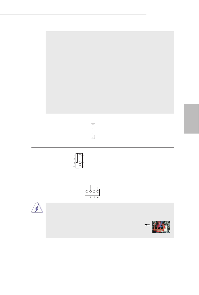
FM2A88M Pro3+
GND
FAN_ VOLTAGE_ CONTR OL
FAN_ SPEED
FAN_ SPEED _CONT ROL
GND
FAN_ VOLTAGE_ CONTR OL
FAN_ SPEED
FAN_ SPEED _CONT ROL
PLED ( システム電源 LED):
シャーシの前面パネルに付いている電源ステータスインジケータに接続しま
す。LED は、システムが動作しているときに点灯します。LED はシステム
が S1 スリープ状態のときに点滅します。システムが S3 または S4 スリープ状
態になるか、電源オフ (S5) になると、LED は消灯します。
HDLED ( ハードドライブアクティビティ LED):
シャーシの前面パネルに付いているハードドライブアクティビティ LED に接続
します。LED は、ハードドライブがデータの読み込みまたは書き込み動作を
しているときに点灯します。
前面パネルのデザインはシャーシによって異なります。前面パネルモジュール
は、主に電源スイッチ、リセットスイッチ、電源 LED、ハードドライブア
クティビティ LED、スピーカーなどから構成されています。シャーシの前面
パネルモジュールをこのヘッダに接続する際は、ワイヤとピンの割り当てが正
しく対応していることを確認してください。
シャーシスピーカーヘッダ
(4 ピン SPEAKER1)
ページ 2, アイテム 7 を参照
ダを接続してください。
シャーシファンコネクタ
(4 ピン CHA_FAN1)
ページ 2, アイテム 10 を参照
SPE AKER
DUM MY
DUM MY
+5V
1
シャーシのスピーカーとこのヘッ
ファンケーブルをファンコネクタ
に接続し、黒いワイヤをアースピ
ンに合わせてください。
CPU ファンコネクタ このコネクタには CPU ファンケー
(4 ピン CPU_FAN1)
ページ 2, アイテム 2 を参照
このマザーボードでは 4 ピン CPU ファン ( クワイエットファン ) がサポートされていますが、
ファン速度コントロール機能がない場合でも、3 ピン CPU ファンは正常に作動します。3
ピン CPU ファンをこのマザーボードの CPU ファンコネクタに接続しようとしている場合、
ピン 1-3 に接続してください。
ブルを接続します。黒いコードは
アースピンに接続してください。
接続されたピン 1-3
3 ピンファンのインストール
日本語
99
Page 100

ATX パワーコネクタ ATX 電源コネクタを接続します。
(24 ピン ATXPWR1)
ページ 2, アイテム 5 を参照
12 124
13
日本語
このマザーボードには 24 ピン ATX 電源コネクタが装備されており、
従来の 20 ピン ATX 電源装置を採用している場合でも作動します。
20 ピン ATX 電源を使用するには、ピン 1 およびピン 13 と共に電源
装置にプラグを差し込みます。
20 ピン ATX 電源装置の取り付け
ATX 12V コネクタ
(4 ピン ATX12V1)
ページ 2, アイテム 1 を参照
源を供給できるように、ATX 12V
プラグを備えたサワーサプライを
このコネクタには CPU に Vcore 電
12
1
24
13
接続する必要があることに注意し
てください。接続に問題があると、電源
は正しく供給されません。
ケース侵入ヘッダ このマザーボードはケースオープン 信
(2 ピン CI1)
ページ 2, アイテム 23 を参照
検出機能に対応しており、シャーシ
カバーが取り外されているかどうか
を検出します。この機能は、
1
Sig nal
GND
シャーシ侵入検出設計を組み込んだ
シャーシを必要とします。
TPM ヘッダー このコネクターはトラステッドプラット
(17 ピン TPMS1)
ページ2, アイテム 6 を参照
フォームモジュール(TPM)システムを
サポートし、鍵、デジタル証明書、パス
ワード、データを安全に保管することが
できます。 TPM システムはまた、ネット
ワークセキュリティを高め、デジタル証
明書を保護し、プラットフォームの完全
PCI RST#
FRA ME
PCI CLK
性を保証します。
100
 Loading...