

Asrock FM2A88M Extreme4+ R2.0 Quick Installation Guide

Copyright Notice:
No part of this documentation may be reproduced, transcribed, transmitted, or
translated in any language, in any form or by any means, except duplication of
documentation by the purchaser for backup purpose, without written consent of
ASRock Inc.
Products and corporate names appearing in this documentation may or may not
be registered trademarks or copyrights of their respective companies, and are used
only for identication or explanation and to the owners’ benet, without intent to
infringe.
Disclaimer:
Specications and information contained in this documentation are furnished for
informational use only and subject to change without notice, and should not be
constructed as a commitment by ASRock. ASRock assumes no responsibility for
any errors or omissions that may appear in this documentation.
With respect to the contents of this documentation, ASRock does not provide
warranty of any k ind, either expressed or implied, including but not limited to
the implied warranties or conditions of merchantability or tness for a particular
purpose.
In no event shall ASRock, its directors, ocers, employees, or agents be liable for
any indirect, special, incidental, or consequential damages (including damages for
loss of prots, loss of business, loss of data, interruption of business and the like),
even if ASRock has been advised of the possibility of such damages arising from any
defect or error in the documentation or product.
e terms HDMI™ and HDMI High-Denition Multimedia Interface, and the HDMI
logo are trademarks or registered trademarks of HDMI Licensing LLC in the United
States and other countries.
is device complies with Part 15 of the FCC Rules. Operation is subject to the following
two conditions:
(1) this device may not cause harmful interference, and
(2) this device must accept any interference received, including interference that
may cause undesired operation.
CALIFORNIA, USA ONLY
e Lithium battery adopted on this motherboard contains Perchlorate, a toxic substance
controlled in Perchlorate Best Management Pract ices (BMP) regulat ions passed by the
California Legislature. When you discard the Lithium battery in California, USA, please
follow the related regulations in advance.
“Perchlorate Material-special handling may apply, see
www.dtsc.ca.gov/hazardouswaste/perchlorate”
e terms HDMI™ and HDMI High-Denition Multimedia Interface, and the HDMI
logo are trademarks or registered trademarks of HDMI Licensing LLC in the United
States and other countries.
English
1

Motherboard Layout
ATXP WR1
DDR 3_A1 (6 4 bit, 24 0-pin m odule )
DDR 3_A2 (6 4 bit, 24 0-pin m odule )
DDR 3_B1 (6 4 bit, 24 0-pin m odule )
DDR 3_B2 (6 4 bit, 24 0-pin m odule )
64Mb
BIOS
Supe r
I/O
ATX12V1
PWR_FAN1
CPU_FAN1
CPU_FAN2
LAN
AUDIO
CODEC
1
CLRCMO S1
Fro nt USB 3. 0
SATA3_1
SATA3_2
SATA3_3
SATA3_4
HDLED RESET
PLED P WRBTN
1
PANEL1
SPEAKER 1
1
IR1
1
PLED1
1
1
USB_5_6
1
USB_7_8
1
USB_9_10
HD_AUD IO1
1
1
LPT1
PCI E1
PCI E3
PCI 1
RoH S
USB 2.0
T:US B3
B: USB4
PS2
Keybo ard/
Mouse
HDM I1
VGA 1
DVI 1
USB 3. 0
T: USB1
B: USB 2
Top:
RJ-4 5
USB 2. 0
T: USB1
B: USB 2
Top:
CTR BASS
Cente r:
REAR SPK
Botto m:
Optic al
SPDIF
Top:
LINE IN
Cente r:
FRONT
Botto m:
MIC IN
1
USB3_3_ 4
PCI E2
CI1
1
SOCKE T FM2 b
AMD
A88 X
(Bo lton- D4)
Chi pset
CHA_FAN1
SATA3_6
SATA3_5
SATA3_8
SATA3_7
COM1
TPMS1
1
PCI E xpres s 3.0
English
2
FM2A88M E xtreme4 +
CMOS
BATT ERY

No. Description
1 ATX 12V Power Connector (ATX12V1)
2 Power Fan Connector (PWR_FAN1)
3 CPU Fan Connector (CPU_FAN1)
4 CPU Fan Connector (CPU_FAN2)
5 2 x 240-pin DDR3 DIMM Slots (DDR3_A1, DDR3_B1)
6 2 x 240-pin DDR3 DIMM Slots (DDR3_A2, DDR3_B2)
7 ATX Power Connector (ATXPWR1)
8 USB 3.0 Header (USB3_3_4)
9 Clear CMOS Jumper (CLRCMOS1)
10 SATA3 Connector (SATA3_7)
11 SATA3 Connector (SATA3_8)
12 SATA3 Connector (SATA3_6)
13 SATA3 Connector (SATA3_5)
14 SATA3 Connector (SATA3_4)
15 SATA3 Connector (SATA3_3)
16 SATA3 Connector (SATA3_1)
17 SATA3 Connector (SATA3_2)
18 System Panel Header (PANEL1)
19 Power LED Header (PLED1)
20 Chassis Speaker Header (SPEAKER1)
21 USB 2.0 Header (USB_5_6)
22 USB 2.0 Header (USB_7_8)
23 USB 2.0 Header (USB_9_10)
24 TPM Header (TPMS1)
25 Print Port Header (LPT1)
26 COM Port Header (COM1)
27 Infrared Module Header (IR1)
28 Front Panel Audio Header (HD_AUDIO1)
29 Chassis Intrusion Header (CI1)
30 Chassis Fan Connector (CHA_FAN1)
FM2A88M Extreme4+ R2.0
English
3

I/O Panel
1 2 3 5
No. Description No. Description
1 USB 2.0 Ports (USB_3_4)* 8 Microphone (Pink)
2 D-Sub Port 9 Optical SPDIF Out Port
3 LAN RJ-45 Port** 10 USB 2.0 Ports (USB_1_2)*
4 Central / Bass (Orange) 11
5 Rear Speaker (Black) 12 HDMI Port
6 Line In (Light Blue) 13 DVI-D Port
7 Front Speaker (Lime)*** 14 PS/2 Mouse/Keyboard Port
USB 3.0 Ports (USB3_1_2)
(AMD A88X (Bolton-D4))
476
891011121314
English
4

FM2A88M Extreme4+ R2.0
* It is recommended to install the USB Keyboard/Mouse c able to USB 2.0 ports (USB_1_2 or
USB_3_ 4) instead of U SB 3.0 por ts.
** There are two LEDs o n the LAN port. Please refer to the table below for the LAN port L ED indica-
tions.
ACT/LINK L ED
SPEED LE D
LAN Por t
Activity / Link LED Speed LED
Status Description Status Description
Off No Link Off 10Mbps connection
Blinking Data Activity Orange 100Mbps connection
On Link Green 1Gbps connection
*** If you use a 2-channel speaker, please connect the speaker ’s plug into “ Front Speaker Jack”. See
the table below for con nection details in accordance w ith the type of speaker you use.
Audio Output
Channels
Front
Speaker
(No. 7)
Rear Speaker
(No. 5)
Central / Bass
(No. 4)
2 V -- -- --
4 V V -- --
6 V V V --
8 V V V V
To enable Multi-Streaming, you need to connect a front panel audio cable to
the front panel audio h eader. After restarting your computer, you will nd the
“Mixer” tool on your system. Please select “Mixer ToolBox” , click “Enable
playback multi-streaming”, and click “ok”. Choose “ 2CH”, “4C H”, “6CH”, or
“8CH” and then you are allowed to select “ Realtek HDA Primar y output ” to
use the Rear Speaker, Centr al/Bass, and Front Speaker, or select “Realtek
HDA Audio 2nd output ” to use the fr ont panel audio.
Line In or
Side Speaker
(No. 6)
English
5

1. Introduction
Thank you for purchasing ASRock FM2A88M Extreme4+ R2.0 motherboard, a reliable motherboard produced under ASRock’s consistently stringent quality control. It
delivers excellent performance with robust design conforming to ASRock’s commitment to quality and endurance.
This Quick Installation Guide contains introduction of the motherboard and step-bystep installation guide. More detailed information of the motherboard can be found
in the user manual presented in the Support CD.
Because the motherboard specications and the BIOS software might be
updated, the content of this manual will be subject to change without no-
tice. In case any modications of this manual occur, the updated version
will be available on ASRock website without further notice. You may nd
the latest VGA cards and CPU support lists on ASRock website as well.
ASRock website http://www.asrock.com
If you require technical support related to this motherboard, please visit
our website for specic information about the model you are using.
www.asrock.com/support/index.asp
1.1 Package Contents
ASRock FM2A88M Extreme4+ R2.0 Motherboard (Micro ATX Form Factor)
ASRock FM2A88M Extreme4+ R2.0 Quick Installation Guide
ASRock FM2A88M Extreme4+ R2.0 Support CD
2 x Serial ATA (SATA) Data Cables (Optional)
1 x I/O Panel Shield
English
6

FM2A88M Extreme4+ R2.0
1.2 Specications
Platform - Micro ATX Form Factor
- All Solid Capacitor design
- High Density Glass Fabric PCB
CPU - Supports Socket FM2+ 95W / FM2 100W processors
- 4 + 2 Power Phase design
Chipset - AMD A88X (Bolton-D4)
Memory - Dual Channel DDR3 Memory Technology
- 4 x DDR3 DIMM Slots
- Supports DDR3 2400+(OC)/2133/1866/1600/1333/1066
non-ECC, un-buffered memory (see CAUTION 1)
- Max. capacity of system memory: 64GB (see CAUTION 2)
- Supports Intel® Extreme Memory Prole (XMP) 1.3 / 1.2
- Supports AMD Memory Prole Technology (AMP) up to AMP
2400
Expansion Slot - 1 x PCI Express 3.0 x16 Slot (PCIE1 @ x16 mode)
* PCIE 3.0 is only supported with FM2+ CPU. With FM2
CPU, it only supports PCIE 2.0.
- 1 x PCI Express 2.0 x16 Slot (PCIE3 @ x4 mode)
- 1 x PCI Express 2.0 x1 Slot
- 1 x PCI Slot
- Supports AMD Quad CrossFireXTM, CrossFireXTM and Dual
Graphics
Graphics - Integrated AMD RadeonTM R7/R5 Series Graphics in
A-series APU
- DirectX 11.1, Pixel Shader 5.0 with FM2+ CPU. DirectX 11,
Pixel Shader 5.0 with FM2 CPU.
- Max. shared memory 2GB
- Three graphics output options: D-Sub, DVI-D and HDMI
Ports
- Supports Triple Monitor
- Supports HDMI with max. resolution up to 4K × 2K
(4096x2160) @ 24Hz
* Only FM2+ APU can support up to 4096x2160 resolution
display via HDMI port
- Supports Dual-link DVI-D with max. resolution up to
2560x1600 @ 60Hz
- Supports D-Sub with max. resolution up to 1920x1200 @
60Hz
English
7
English
- Supports Auto Lip Sync, Deep Color (12bpc), xvYCC and
HBR (High Bit Rate Audio) with HDMI Port (Compliant HDMI
monitor is required) (see CAUTION 3)
- Supports Blu-ray Stereoscopic 3D with HDMI Port
- Supports AMD Steady VideoTM 2.0: New video post
processing capability for automatic jitter reduction on
home/online video
- Supports HDCP with DVI-D and HDMI Ports
- Supports Full HD 1080p Blu-ray (BD) playback with DVI-D
and HDMI Ports
Audio - 7.1 CH HD Audio with Content Protection (Realtek ALC892
Audio Codec)
- Premium Blu-ray Audio support
- Supports Surge Protection (ASRock Full Spike Protection)
LAN - PCIE x1 Gigabit LAN 10/100/1000 Mb/s
- Qualcomm® Atheros® AR8171
- Supports Qualcomm® Atheros® Security Wake On Internet
Technology
- Supports Wake-On-LAN
- Supports Lightning/ESD Protection (ASRock Full Spike
Protection)
- Supports Energy Efcient Ethernet 802.3az
- Supports PXE
Rear Panel I/O - 1 x PS/2 Mouse/Keyboard Port
- 1 x D-Sub Port
- 1 x DVI-D Port
- 1 x HDMI Port
- 1 x Optical SPDIF Out Port
- 4 x USB 2.0 Ports (Supports ESD Protection (ASRock Full
Spike Protection))
- 2 x USB 3.0 Ports (AMD A88X (Bolton-D4)) (Supports ESD
Protection (ASRock Full Spike Protection))
- 1 x RJ-45 LAN Port with LED (ACT/LINK LED and SPEED
LED)
- HD Audio Jacks: Rear Speaker/Central/Bass/Line in/Front
Speaker/Microphone
Storage - 8 x SATA3 6.0 Gb/s Connectors, support RAID (RAID 0,
RAID 1, RAID 5 and RAID 10), NCQ, AHCI and Hot Plug
Connector - 1 x IR Header
- 1 x Print Port Header
- 1 x COM Port Header
8

FM2A88M Extreme4+ R2.0
- 1 x Chassis Intrusion Header
- 1 x TPM Header
- 1 x Power LED Header
- 2 x CPU Fan Connectors (1 x 4-pin, 1 x 3-pin)
- 1 x Chassis Fan Connector (4-pin)
- 1 x Power Fan Connector (3-pin)
- 1 x 24 pin ATX Power Connector
- 1 x 8 pin 12V Power Connector
- 1 x Front Panel Audio Connector
- 3 x USB 2.0 Headers (Support 6 USB 2.0 ports) (Supports
ESD Protection (ASRock Full Spike Protection))
- 1 x USB 3.0 Header by AMD A88X (Bolton-D4) (Supports 2
USB 3.0 ports) (Supports ESD Protection (ASRock Full
Spike Protection))
BIOS Feature - 64Mb AMI UEFI Legal BIOS with GUI support
- Supports “Plug and Play”
- ACPI 1.1 Compliant wake up events
- Supports jumperfree
- SMBIOS 2.3.1 support
- DRAM, CPU Voltage multi-adjustment
Hardware - CPU temperature sensing
Monitor - Chassis temperature sensing
- CPU Fan Tachometer
- Chassis Fan Tachometer
- CPU/Chassis Quiet Fan
- CPU/Chassis Fan multi-speed control
- CASE OPEN detection
- Voltage monitoring: +12V, +5V, +3.3V, Vcore
OS - Microsoft® Windows® 10 32-bit / 10 64-bit / 8.1 32-bit / 8.1
64-bit / 8 32-bit / 8 64-bit / 7 32-bit / 7 64-bit
* For the updated Windows® 10 driver, please visit ASRock’s
website for details: http://www.asrock.com
* Carrizo FM2r2 processor supports Windows® 10 64-bit / 8.1
64-bit / 7 32-bit / 7 64-bit only.
Certications - FCC, CE, WHQL
- ErP/EuP ready (ErP/EuP ready power supply is required)
* For detailed product information, please visit our website: http://www.asrock.com
English
9

WARNING
Please realize that there is a certain risk involved with overclocking,
including adjusting the setting in the BIOS, applying Untied Overclocking
Technology, or using third-party overclocking tools. Overclocking may
affect your system’s stability, or even cause damage to the components
and devices of your system. It should be done at your own risk and
expense. We are not responsible for possible damage caused by
overclocking.
CAUTION!
1. Whether 2400/2133/1866/1600MHz memory speed is supported depends on the CPU you adopt. If you want to adopt DDR3
2400/2133/1866/1600 memory module on this motherboard,
please refer to the memory support list on our website for the
compatible memory modules.
ASRock website http://www.asrock.com
2. Due to the operating system limitation, the actual memory size
may be less than 4GB for the reservation for system usage under Windows® 10 / 8.1 / 8 / 7. For Windows® 64-bit OS with 64bit CPU, there is no such limitation.
3. xvYCC and Deep Color are only supported under Windows®
10 64-bit / 10 / 8.1 64-bit / 8.1 / 8 64-bit / 8 / 7 64-bit / 7. Deep
Color mode will be enabled only if the display supports 12bpc
in EDID. HBR is supported under Windows® 10 64-bit / 10 / 8.1
64-bit / 8.1 / 8 64-bit / 8 / 7 64-bit / 7.
English
10

FM2A88M Extreme4+ R2.0
2. Installation
This is a Micro ATX form factor motherboard. Before you install the motherboard,
study the conguration of your chassis to ensure that the motherboard ts into it.
Pre-installation Precautions
Take note of the following precautions before you install motherboard
components or change any motherboard settings.
Before you install or remove any component, ensure that the
power is switched off or the power cord is detached from the
power supply. Failure to do so may cause severe damage to the
motherboard, peripherals, and/or components.
1. Unplug the power cord from the wall socket before touching any
component.
2. To avoid damaging the motherboard components due to static electricity, NEVER place your motherboard directly on the carpet or the
like. Also remember to use a grounded wrist strap or touch a safety
grounded object before you handle components.
3. Hold components by the edges and do not touch the ICs.
4. Whenever you uninstall any component, place it on a grounded antistatic pad or in the bag that comes with the component.
5. When placing screws into the screw holes to secure the motherboard to the chassis, please do not over-tighten the screws! Doing
so may damage the motherboard.
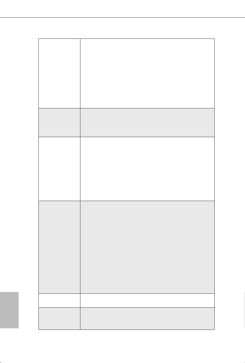
2.1 CPU Installation
Step 1. Unlock the socket by lifting the lever up
to a 90
o
angle.
English
11
Step 2. Position the CPU directly above the
socket such that the CPU corner with
the golden triangle matches the socket
corner with a small triangle.
Step 3. Carefully insert the CPU into the
socket until it ts in place.
The CPU ts only in one correct
orientation. DO NOT force the CPU
into the socket to avoid bending of
the pins.
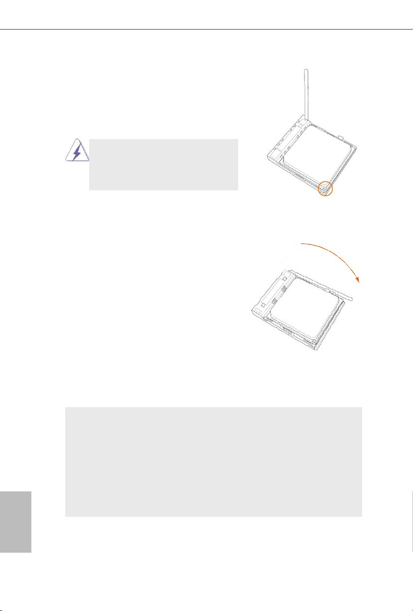
Step 4. When the CPU is in place, press it
rmly on the socket while you push
down the socket lever to secure the
CPU. The lever clicks on the side tab
to indicate that it is locked.
English
12
2.2 Installation of CPU Fan and Heatsink
After you install the CPU into this motherboard, it is necessary to install a
larger heatsink and cooling fan to dissipate heat. You also need to spray
thermal grease between the CPU and the heatsink to improve heat dissipation. Make sure that the CPU and the heatsink are securely fastened
and in good contact with each other. Then connect the CPU fan to the
CPU FAN connector (CPU_FAN1, see Page 2, No. 3 or CPU_FAN2, see
Page 2, No. 4). For proper installation, please kindly refer to the instruction manuals of the CPU fan and the heatsink.
FM2A88M Extreme4+ R2.0
2.3 Installation of Memory Modules (DIMM)
This motherboard provides four 240-pin DDR3 (Double Data Rate 3) DIMM
slots, and supports Dual Channel Memory Technology.
1.
For dual channel con gurati on, you always need to install identical (the
same brand, speed, s ize and chip -type) DDR3 DIMM pairs.
2.
It is unable to activate Dual Channel Memory Technology with only one or
three memory module installed.
3.
It is not al lowed to install a DDR or DDR2 memor y module into a DDR3
slot; otherwise, this motherboard and D IMM may be damaged.
4.
If you adopt DDR3 240 0/2133/1866/160 0 memory modules on this motherboar d, it is reco mmended to install them on DDR3_A2 and D DR3_ B2
slots.
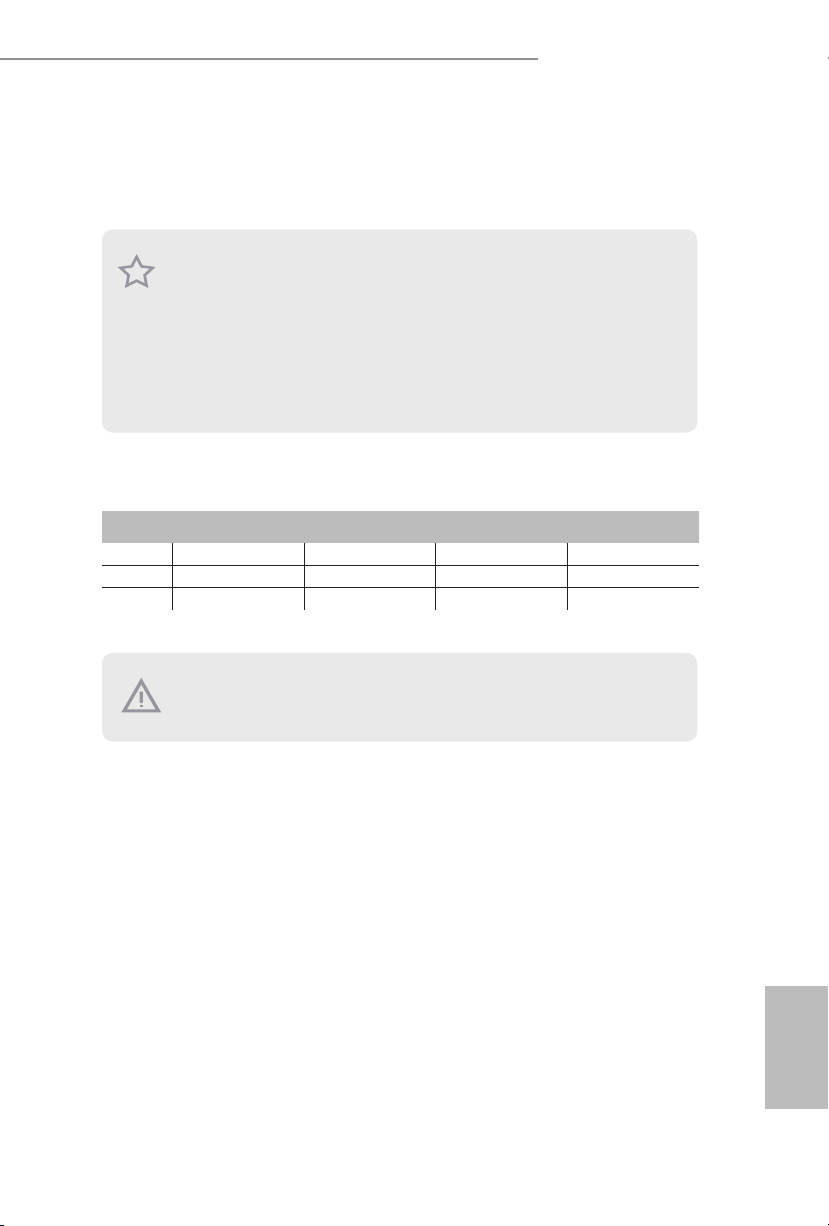
Dual Channel Memory Conguration
Priority DDR3_A1 DDR3_A2 DDR3_B1 DDR3_B2
1 Populated Populated
2 Populated Populated
3 Populated Populated Populated Populated
The DIM M only ts in one correct orientation. It will cause per manent dam age to the mo therboard and the DIM M if you force the DIMM into the slot at
incorrect orientation.
English
13

1
2
English
14
3

FM2A88M Extreme4+ R2.0
2.4 Expansion Slots (PCI and PCI Express Slots)
There is 1 PCI slot and 3 PCI Express slots on this motherboard.
Before installing an expansion card, please make sure that the power supply
is switched off or the power cord is unplugged. Please read the documentation of the expansion card and make nec essary hardware settings for the
card before you star t the insta llation.
PCI Slots: PCI slots are used to install expansion cards that have the 32-bit PCI
interface.
PCIE Slots:
PCIE1 (PCIe 3.0 x16 slot) is used for PCI Express x16 lane width graph-
ics cards.
PCIE2 (PCIe 2.0 x1 slot) is used for PCI Express cards with x1 lane
width cards.
PCIE3 (PCIe 2.0 x16 slot) is used for PCI Express x4 lane width graph-
ics cards.
PCIe Slot Congurations
PCIE1 PCIE3
Single Graphics Card x16 N/A
Two Graphics Cards in
CrossFireXTM Mode
For a better thermal environment , please connect a chassis fan to the moth erboar d’s chassis fan connec tor (CHA _FAN1) when us ing multiple graphics
cards.
x16 x4
English
15

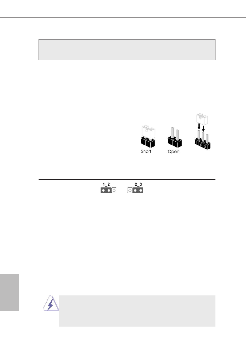
2.5 Jumpers Setup
The illustration shows how jumpers are
setup. When the jumper cap is placed on
pins, the jumper is “Short”. If no jumper cap
is placed on pins, the jumper is “Open”. The
illustration shows a 3-pin jumper whose
pin1 and pin2 are “Short” when jumper cap
is placed on these 2 pins.
Jumper Setting Description
Clear CMOS Jumper
(CLRCMOS1)
(see p.2, No. 9)
Note: CLRCMOS1 allows you to clear the data in CMOS. To clear and reset the
system parameters to default setup, please turn off the computer and unplug
the power cord from the power supply. After waiting for 15 seconds, use a
jumper cap to short pin2 and pin3 on CLRCMOS1 for 5 seconds. However,
please do not clear the CMOS right after you update the BIOS. If you need
to clear the CMOS when you just nish updating the BIOS, you must boot
up the system rst, and then shut it down before you do the clear-CMOS action. Please be noted that the password, date, time, user default prole, 1394
GUID and MAC address will be cleared only if the CMOS battery is removed.
If you clear the CMOS, the case open may be detected. Please adjust the
BIOS option “Clear Status” to clear the record of previous chassis intrusion
status.
Clear CMOSDefault
English
16

FM2A88M Extreme4+ R2.0
USB _PWR
2.6 Onboard Headers and Connectors
Onboard headers and connectors are NOT jumpers. Do NOT place
jumper caps over these headers and connectors. Placing jumper caps
over the headers and connectors will cause permanent damage of the
motherboard!
Serial ATA3 Connectors These eight Serial ATA3
(SATA3_1: see p.2, No. 16)
(SATA3_2: see p.2, No. 17)
(SATA3_3: see p.2, No. 15)
(SATA3_4: see p.2, No. 14)
(SATA3_5: see p.2, No. 13)
(SATA3_6: see p.2, No. 12)
(SATA3_7: see p.2, No. 10)
(SATA3_8: see p.2, No. 11)
(SATA3) connectors support
SATA data cables for internal
storage devices. The current
SATA3 interface allows up to
6.0 Gb/s data transfer rate.
SATA3_2 SATA3_4
SATA3_1 SATA3_3
SATA3_5 SATA3_7
SATA3_6 SATA3_8
USB 2.0 Headers Besides four default USB 2.0
(9-pin USB_5_6)
(see p.2 No. 21)
ports on the I/O panel, there
are three USB 2.0 headers on
this motherboard. Each USB 2.0
header can support two USB
(9-pin USB_7_8)
(see p.2 No. 22)
(9-pin USB_9_10)
(see p.2 No. 23)
2.0 ports.
USB 3.0 Header Besides two default USB 3.0
(19-pin USB3_3_4)
(see p.2, No. 8)
ports on the I/O panel, there is
one USB 3.0 header on this
motherboard. This USB 3.0
header can support two USB 3.0
ports.
USB _PWR
1
USB _PWR
USB _PWR
1
USB _PWR
USB _PWR
1
Vbu s
Int A_P3_ SSRX-
Int A_P3_ SSRX+
GND
Int A_P3_ SSTX-
Int A_P3_ SSTX+
GND
Int A_P3_ D-
Int A_P3_ D+
P-6
P-5
P-8
P-7
P-1 0
P-9
P+6
P+5
P+8
P+7
P+1 0
P+9
GND
GND
GND
GND
GND
GND
DUM MY
DUM MY
DUM MY
Vbu sVbu s
Int A_P4_ SSRX-
Int A_P4_ SSRX+
GND
Int A_P4_ SSTX-
Int A_P4_ SSTX+
GND
Int A_P4_ D-
Int A_P4_ D+
DUM MY
English
17

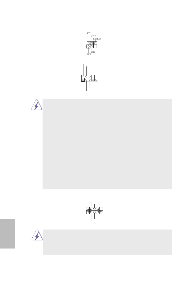
Infrared Module Header This header supports an
GND
RESE T#
PWRB TN#
PLED -
PLED +
GND
HDLE D-
HDLE D+
1
GND
(5-pin IR1)
optional wireless transmitting
(see p.2 No. 27)
and receiving infrared module.
Front Panel Audio Header This is an interface for the front
(9-pin HD_AUDIO1)
(see p.2 No. 28)
panel audio cable that allows
convenient connection and
control of audio devices.
1
GND
PRE SENCE #
MIC 2_R
MIC 2_L
MIC _RET
J_S ENSE
OUT 2_R
OUT _RET
OUT 2_L
1. High Denition Audio supports Jack Sensing, but the panel wire on
the chassis must support HDA to function correctly. Please follow the
instruction in our manual and chassis manual to install your system.
2. If you use AC’97 audio panel, please install it to the front panel audio
header as below:
A. Connect Mic_IN (MIC) to MIC2_L.
B. Connect Audio_R (RIN) to OUT2_R and Audio_L (LIN) to OUT2_L.
C. Connect Ground (GND) to Ground (GND).
D. MIC_RET and OUT_RET are for HD audio panel only. You don’t
need to connect them for AC’97 audio panel.
E. To activate the front mic.
For Windows® 8.1 / 8.1 64-bit / 7 / 7 64-bit 64-bit OS:
Go to the "FrontMic" Tab in the Realtek Control panel. Adjust
“Recording Volume”.
System Panel Header This header accommodates
(9-pin PANEL1)
(see p.2 No. 18)
several system front panel
functions.
English
Connect the power switch, reset switch and system status indicator
on the chassis to this header according to the pin assignments below.
Note the positive and negative pins before connecting the cables.
PWRBTN (Power Switch):
Connect to the power switch on the chassis front panel. You may con-
gure the way to turn off your system using the power switch.
18

FM2A88M Extreme4+ R2.0
1
+5V
DUM MY
DUM MY
SPE AKER
GND
+12 V
PWR _FAN_ SPEED
RESET (Reset Switch):
Connect to the reset switch on the chassis front panel. Press the reset
switch to restart the computer if the computer freezes and fails to perform a normal restart.
PLED (System Power LED):
Connect to the power status indicator on the chassis front panel. The
LED is on when the system is operating. The LED keeps blinking
when the sys-tem is in S1 sleep state. The LED is off when the system
is in S3/S4 sleep state or powered off (S5).
HDLED (Hard Drive Activity LED):
Connect to the hard drive activity LED on the chassis front panel. The
LED is on when the hard drive is reading or writing data.
The front panel design may differ by chassis. A front panel module
mainly consists of power switch, reset switch, power LED, hard drive
activity LED, speaker and etc. When connecting your chassis front
panel module to this header, make sure the wire assignments and the
pin assign-ments are matched correctly.
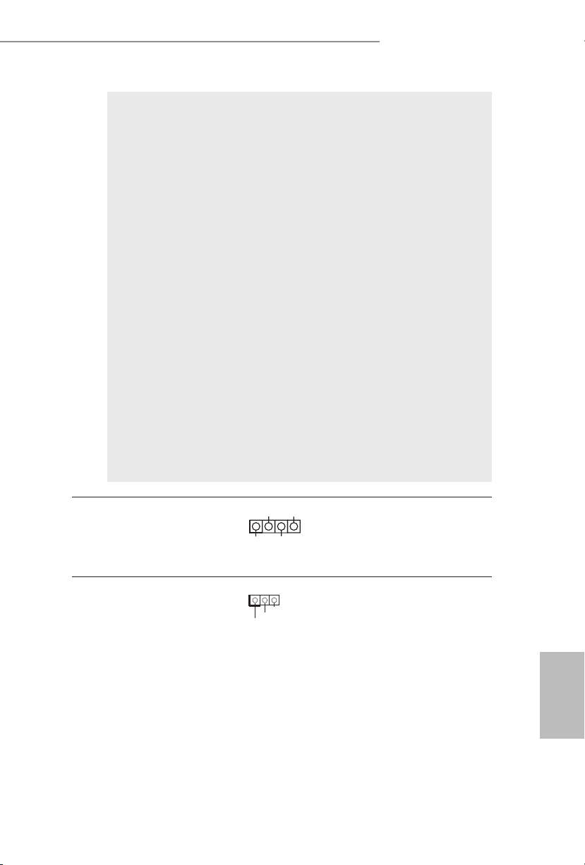
Chassis Speaker Header Please connect the chassis
(4-pin SPEAKER 1)
(see p.2 No. 20)
speaker to this header.
Power LED Header Please connect the chassis
(3-pin PLED1)
(see p.2 No. 19)
power LED to this header to
indicate system power status.
1
PLE D+
PLE D+
PLE D-
The LED is on when the system
is operating. The LED keeps
blinking in S1 state. The LED is
off in S3/S4 state or S5 state
(power off).
Chassis and Power Fan Connectors Please connect the fan cables
(4-pin CHA_FAN1)
(see p.2 No. 30)
to the fan connectors and
match the black wire to the
CHA _FAN_ SPEED
+12 V
FAN _SPEE D_CON TROL
GND
ground pin. CHA_FAN1 fan
(3-pin PWR_FAN1)
(see p.2 No. 2)
speed can be controlled through
UEFI or A-Tuning.
English
19

CPU Fan Connectors Please connect the CPU fan
(4-pin CPU_FAN1)
(see p.2 No. 3)
cable to the connector and
match the black wire to the
ground pin.
FAN_ SPEED _CONT ROL
CPU _FAN_S PEED
+12 V
GND
1 2 3 4
Though this motherboard provides 4-Pin CPU fan (Quiet Fan) support, the 3-Pin
CPU fan still can work successfully even without the fan speed control function.
If you plan to connect the 3-Pin CPU fan to the CPU fan connector on this
motherboard, please connect it to Pin 1-3.
Pin 1-3 Connected
3-Pin Fan Installation
English
(3-pin CPU_FAN2)
(see p.2 No. 4)
ATX Power Connector Please connect an ATX power
(24-pin ATXPWR1)
(see p.2 No. 7)
Though this motherboard provides 24-pin ATX power connector,
it can still work if you adopt a traditional 20-pin ATX power supply.
GND
+12 V
12
CPU _FAN_S PEED
24
supply to this connector.
1
13
12
To use the 20-pin ATX power supply, please plug your power
supply along with Pin 1 and Pin 13.
20-Pin ATX Power Supply Installation
ATX 12V Power Connector Please connect an ATX 12V
(8-pin ATX12V1)
(see p.2 No. 1)
power supply to this connector.
4 8
1 5
1
Though this motherboard provides 8-pin ATX 12V power connector, it can still work
if you adopt a traditional 4-pin ATX 12V power supply. To use the
4 8
4-pin ATX power supply, please plug your power supply along with
Pin 1 and Pin 5.
4-Pin ATX 12V Power Supply Installation
1 5
24
13
20

FM2A88M Extreme4+ R2.0
CCT S#1
RRTS #1
DDS R#1
DDT R#1
RRX D1
GND
TTXD 1
DDC D#1
1
RRI #1
1
Serial port Header This COM1 header supports a
(9-pin COM1)
(see p.2 No. 26)
Chassis Intrusion Header This motherboard supports
(2-pin CI1)
(see p.2, No. 29)
has been removed. This feature
requires a chassis with chassis
intrusion detection design.
serial port module.
CASE OPEN detection feature
that detects if the chassis cover
1
Sig nal
GND
Print Port Header This is an interface for print
(25-pin LPT1)
(see p.2, No. 25)
port cable that allows
convenient connection of printer
devices.
1
AFD #
STB #
ERR OR#
PIN IT#
SPD 1
SPD 0
SLI N#
SPD 2
SPD 3
SPD 4
SPD 5
SPD 6
GND
SPD 7
ACK #
BUS Y
PE
SLC T
TPM Header This connector supports
(17-pin TPMS1)
(see p.2, No. 24)
Trusted Platform Module (TPM)
system, which can securely
store keys, digital certicates,
passwords, and data. A TPM
system also helps enhance
network security, protects
digital identities, and ensures
platform integrity.
English
21

1. Einführung
Wir danken Ihnen für den Kauf des ASRock FM2A88M Extreme4+ R2.0 Motherboard, ein zuverlässiges Produkt, welches unter den ständigen, strengen Qualitätskontrollen von ASRock gefertigt wurde. Es bietet Ihnen exzellente Leistung und
robustes Design, gemäß der Verpichtung von ASRock zu Qualität und Halbarkeit.
Diese Schnellinstallationsanleitung führt in das Motherboard und die schrittweise
Installation ein. Details über das Motherboard nden Sie in der Bedienungsanleitung
auf der Support-CD.
Da sich Motherboard-Spezikationen und BIOS-Software verändern
können, kann der Inhalt dieses Handbuches ebenfalls jederzeit geändert
werden. Für den Fall, dass sich Änderungen an diesem Handbuch
ergeben, wird eine neue Version auf der ASRock-Website, ohne weitere
Ankündigung, verfügbar sein. Die neuesten Grakkarten und unterstützten
CPUs sind auch auf der ASRock-Website aufgelistet.
ASRock-Website: http://www.asrock.com
Wenn Sie technische Unterstützung zu Ihrem Motherboard oder spezische
Informationen zu Ihrem Modell benötigen, besuchen Sie bitte unsere
Webseite:
www.asrock.com/support/index.asp
1.1 Kartoninhalt
ASRock FM2A88M Extreme4+ R2.0 Motherboard (Micro ATX-Formfaktor)
ASRock FM2A88M Extreme4+ R2.0 Schnellinstallationsanleitung
ASRock FM2A88M Extreme4+ R2.0 Support-CD
Zwei Serial ATA (SATA) -Datenkabel (optional)
Ein I/O Shield
Deutsch
22

FM2A88M Extreme4+ R2.0
1.2 Spezikationen
Plattform - Micro ATX-Formfaktor
- Vollständig solides Kondensatordesign
- PCB mit hochverdichtetem Glasfasergewebe
CPU - Unterstützt Prozessoren für Sockel FM2+ (95 W) /
FM2 (100 W)
- 4 + 2-Stromphasendesign
Chipsatz - AMD A88X (Bolton-D4)
Speicher - Unterstützung von Dual-Kanal-Speichertechnologie
- 4 x Steckplätze für DDR3
- Unterstützt DDR3 2400+(OC)/2133/1866/1600/1333/1066
non-ECC, ungepufferter Speicher
- Max. Kapazität des Systemspeichers: 64GB
- Unterstützt Intel® Extreme Memory Prole (XMP)1.3/1.2
- Unterstützt AMDs Memory Prole Technology (AMP) bis
AMP 2400
Erweiterungs- - 1 x PCI Express 3.0 x16-Steckplatz
steckplätze * PCIE 3.0 wird nur mit FM2+-Prozessor unterstützt.
FM2-Prozessor unterstützt nur PCIE 2.0.
- 1 x PCI Express 2.0 x16-Steckplatz (PCIE3: x4-Modus)
- 1 x PCI Express 2.0 x1-Steckplatz
- 1 x PCI -Steckplatz
- Unterstützt AMD Quad CrossFireXTM, CrossFireXTM und
duale Grakkarten
Onboard-VGA - Integrierte Grakkarte der AMD RadeonTM R7/R5-Serie in
APU der A-Serie
- DirectX 11.1, Pixel Shader 5.0 mit FM2+-Prozessor. DirectX
11, Pixel Shader 5.0 mit FM2-Prozessor.
- Maximal gemeinsam genutzter Speicher 2GB
- Drei VGA-Ausgangsoptionen: D-Sub, DVI-D sowie HDMI
- Unterstützt drei Monitore
- Unterstützt HDMI mit einer maximalen Auösung von
4K x 2K (4096 x 2160) bei 24 Hz
* Nur FM2 + APU kann bis zu 4096x2160 Auösung Anzeige
über HDMI-Anschluss unterstützt
- Unterstützt Dual-link DVI-D mit einer maximalen Auösung
von 2560 x 1600 bei 60 Hz
- Unterstützt D-Sub mit einer maximalen Auösung von
1920 x 1200 bei 60 Hz
(PCIE1: x6-Modus)
Deutsch
23

Deutsch
- Unterstützt Auto Lip Sync, Deep Color (12bpc), xvYCC
und HBR (High Bit Rate-Audio) mit HDMI (kompatibler
HDMI-Bildschirm erforderlich)
- Unterstützt stereoskopisches 3D per Blu-ray mit HDMI
- Unterstützt AMD Steady VideoTM 2.0: Neuartige Funktion der
Videonachbearbeitung für automatische Reduzierung von
Bildschwankungen bei Heim-/Online-Videos
- Unterstützt HDCP mit DVI-D- und HDMI-Ports
- Unterstutzt 1080p Blu-ray (BD)-Wiedergabe mit DVI-D- und
HDMI-Ports
Audio - 7.1-Kanal-HD-Audio mit Inhaltsschutz (Realtek ALC892-
Audiocodec)
- Erstklassige Blu-ray-Audiounterstützung
- Unterstützt Überspannungsschutz (ASRocks
Komplettschutz vor Spannungsspitzen)
LAN - PCIE x1 Gigabit LAN 10/100/1000 Mb/s
- Qualcomm® Atheros® AR8171
- Unterstützt Qualcomm® Atheros® Security Wake On
Internet-Technologie
- Unterstützt Wake-On-LAN
- Unterstützt Schutz vor Blitzschlag/elektrostatischer
Entladung (ASRocks Komplettschutz vor
Spannungsspitzen)
- Unterstützt energieefzientes Ethernet 802.3az
- Unterstützt PXE
E/A-Anschlüsse - 1 x PS/2-Maus/Tastaturanschluss
an der - 1 x D-Sub port
Rückseite - 1 x DVI-D port
- 1 x HDMI port
- 1 x optischer SPDIF-Ausgang
- 4 x Standard-USB 2.0-Anschlüsse (Unterstützt Schutz vor
elektrostatischer Entladung (ASRocks Komplettschutz vor
Spannungsspitzen))
- 2 x Standard-USB 3.0-Anschlüsse (AMD A88X (Bolton-D4))
(Unterstützt Schutz vor elektrostatischer Entladung
(ASRocks Komplettschutz vor Spannungsspitzen))
- 1 x RJ-45 LAN Port mit LED (ACT/LINK LED und SPEED
LED)
- HD Audiobuchse: Lautsprecher hinten / Mitte/Bass /
Audioeingang / Lautsprecher vorne / Mikrofon
24

FM2A88M Extreme4+ R2.0
Speicher - 8 x SATA 3-Anschluss mit 6,0 Gb/s, unterstützt RAID (RAID 0, RAID 1, RAID 5 und RAID 10), NCQ-, AHCI- und
„Hot Plugging“-Funktionen
Anschlüsse - 1 x Infrarot-Modul-Header
- 1 x Druckerport-Anschlussleiste
- 1 x COM-Anschluss-Header
- 1 x Verteiler für Gehäuseeindringversuche
- 1 x TPM-Stiftleiste
- 1 x Betriebs-LED-Header
- 2 x CPUlüfter-Anschluss (1 x 4-pin, 1 x 3-pin)
- 1 x Gehäuselüfter-Anschluss (4-pin)
- 1 x Stromlüfter-Anschluss (3-pin)
- 1 x 24-pin ATX-Netz-Header
- 1 x 8-pin anschluss für 12V-ATX-Netzteil
- 1 x Anschluss für Audio auf der Gehäusevorderseite
- 3 x USB 2.0-Anschlüsse (Unterstützung 6 zusätzlicher
USB 2.0-Anschlüsse) (Unterstützt Schutz vor
elektrostatischer Entladung (ASRocks Komplettschutz vor
Spannungsspitzen))
- 1 x USB 3.0-Anschlüsse über AMD A88X (Bolton-D4)
(Unterstützung 2 zusätzlicher USB 3.0-Anschlüsse)
(Unterstützt Schutz vor elektrostatischer Entladung
(ASRocks Komplettschutz vor Spannungsspitzen))
BIOS - 64Mb AMIs Legal BIOS UEFI mit GUI-Unterstützung
- Unterstützung für “Plug and Play”
- ACPI 1.1-Weckfunktionen
- JumperFree-Modus
- SMBIOS 2.3.1
- DRAM und CPU Stromspannung Multianpassung
Hardware Monitor - CPU-Temperatursensor
- Motherboardtemperaturerkennung
- Drehzahlmessung für CPUlüfter
- Drehzahlmessung für Gehäuselüfter
- Geräuscharmer CPU/Gehäuselüfter
- Mehrstuge Geschwindigkeitsteuerung für CPU-/
Gehäuselüfter
- GEHÄUSE OFFEN-Erkennung
- Spannungsüberwachung: +12V, +5V, +3.3V, Vcore
Betriebssysteme - Unterstützt Microsoft
32-Bit / 7 64-Bit
®
Windows® 8.1 32-Bit / 8.1 64-Bit / 7
Deutsch
25
Deutsch
Zertizierungen - FCC, CE, WHQL
- Gemäß Ökodesign-Richtlinie (ErP/EuP) (Stromversorgung
gemäß Ökodesign-Richtlinie (ErP/EuP) erforderlich)
* Für die ausführliche Produktinformation, besuchen Sie bitte unsere Website:
http://www.asrock.com
1.3 Einstellung der Jumper
Die Abbildung verdeutlicht, wie Jumper
gesetzt werden. Werden Pins durch
Jumperkappen verdeckt, ist der Jumper
“Gebrückt”. Werden keine Pins durch
Jumperkappen verdeckt, ist der Jumper
“Offen”. Die Abbildung zeigt einen 3-Pin
Jumper dessen Pin1 und Pin2 “Ge-
brückt” sind, bzw. es bendet sich eine
Jumper-Kappe auf diesen beiden Pins.
Jumper Einstellun Beschreibung
CMOS löschen
(CLRCMOS1, 3-Pin jumper)
(siehe S.2, No. 9)
Hinweis:
CLRCMOS1 ermöglicht Ihnen die Löschung der Daten im CMOS. Zum
Löschen und Zurücksetzen der Systemparameter auf die Standardeinrichtung
schalten Sie den Computer bitte aus und trennen das Netzkabel von der
Stromversorgung. Warten Sie 15 Sekunden, schließen Sie dann Pin2 und
Pin3 am CLRCMOS1 über einen Jumper fünf Sekunden lang kurz. Sie
sollten das CMOS allerdings nicht direkt nach der BIOS-Aktualisierung
löschen. Wenn Sie das CMOS nach Abschluss der BIOS-Aktualisierung
löschen müssen, fahren Sie zuerst das System hoch. Fahren Sie es dann
vor der CMOS-Löschung herunter. Bitte beachten Sie, dass Kennwort,
Datum, Uhrzeit, benutzerdeniertes Prol, 1394 GUID und MAC-Adresse
nur gelöscht werden, wenn die CMOS-Batterie entfernt wird.
DefaultEinstellung
CMOS
löschen
26
Durch Löschen des CMOS kann erkannt werden, wenn das
Gehäuseoffen ist. Bitte stellen Sie zum Löschen der Aufzeichnung des
vorherigenGehäuseindringungsstatus die BIOS-Option “Status leeren”
ein.

FM2A88M Extreme4+ R2.0
1.4 Anschlüsse
Anschlussleisten sind KEINE Jumper. Setzen Sie KEINE Jumperkappen
auf die Pins der Anschlussleisten. Wenn Sie die Jumperkappen auf die
Anschlüsse setzen, wird das Motherboard permanent beschädigt!
Anschluss Beschreibung
Seriell-ATA3-Anschlüsse Diese acht Serial ATA3-
(SATA3_1: siehe S.2 - No. 16)
(SATA3_2: siehe S.2 - No. 17)
(SATA3_3: siehe S.2 - No. 15)
(SATA3_4: siehe S.2 - No. 14)
(SATA3_5: siehe S.2 - No. 13)
(SATA3_6: siehe S.2 - No. 12)
(SATA3_7: siehe S.2 - No. 10)
(SATA3_8: siehe S.2 - No. 11)
(SATA3-)Verbínder
unterstützten SATA-Datenkabel
für interne
Massenspeichergeräte. Die
aktuelle SATA3- Schnittstelle
ermöglicht eine
SATA3_2 SATA3_4
SATA3_5 SATA3_7
SATA3_6 SATA3_8
Datenübertragungsrate bis
6,0 Gb/s.
SATA3_1 SATA3_3
USB 2.0-Header Zusätzlich zu den vier
(9-pol. USB_5_6)
(siehe S.2 - No. 21)
üblichen USB 2.0-Ports an den
I/O-Anschlüssen benden sich
drei USB 2.0-
Anschlussleisten am
(9-pol. USB_7_8)
(siehe S.2 - No. 22)
Motherboard. Pro USB 2.0-
Anschlussleiste werden zwei
USB 2.0-Ports unterstützt.
(9-pol. USB_9_10)
(siehe S.2 - No. 23)
USB 3.0-Header Neben zwei Standard-USB
(19-pol. USB3_3_4)
(siehe S.2 - No. 8)
3.0-Ports am E/A-Panel
bendet sich ein USB 3.0-
Header an diesem
Motherboard. Dieser USB 3.0 Header kann zwei USB 3.0 Ports unterstützen.
USB _PWR
1
USB _PWR
USB _PWR
1
USB _PWR
USB _PWR
1
USB _PWR
Vbu s
Int A_P3_ SSRX-
Int A_P3_ SSRX+
GND
Int A_P3_ SSTX-
Int A_P3_ SSTX+
GND
Int A_P3_ D-
Int A_P3_ D+
P-6
P-5
P-8
P-7
P-1 0
P-9
P+6
P+5
P+8
P+7
P+1 0
P+9
GND
GND
GND
GND
GND
GND
DUM MY
DUM MY
DUM MY
Vbu sVbu s
Int A_P4_ SSRX-
Int A_P4_ SSRX+
GND
Int A_P4_ SSTX-
Int A_P4_ SSTX+
GND
Int A_P4_ D-
Int A_P4_ D+
DUM MY
Deutsch
27
Infrarot-Modul-Header Dieser Header unterstützt ein
GND
RESE T#
PWRB TN#
PLED -
PLED +
GND
HDLE D-
HDLE D+
1
GND
(5-pin IR1)
optionales, drahtloses Sende-
(siehe S.2 - No. 27)
und Empfangs-Infrarotmodul.
Anschluss für Audio auf Dieses Interface zu einem
der Gehäusevorderseite Audio-Panel auf der Vorder
(9-Pin HD_AUDIO1)
(siehe S.2 - No. 28)
seite Ihres Gehäuses,
ermöglicht Ihnen eine bequeme
Anschlussmöglichkeit und
Kontrolle über Audio-Geräte.
1
GND
PRE SENCE #
MIC 2_R
MIC 2_L
MIC _RET
J_S ENSE
OUT 2_R
OUT _RET
OUT 2_L
1. High Denition Audio unterstützt Jack Sensing (automatische Erkennung
falsch angeschlossener Geräte), wobei jedoch die Bildschirmverdrahtung
am Gehäuse HDA unterstützen muss, um richtig zu funktionieren.
Beachten Sie bei der Installation im System die Anweisungen in unserem
Handbuch und im Gehäusehandbuch.
2. Wenn Sie die AC’97-Audioleiste verwenden, installieren Sie diese wie
nachstehend beschrieben an der Front-Audioanschlussleiste:
A. Schließen Sie Mic_IN (MIC) an MIC2_L an.
B. Schließen Sie Audio_R (RIN) an OUT2_R und Audio_L (LIN) an OUT2_L an.
C. Schließen Sie Ground (GND) an Ground (GND) an.
D. MIC_RET und OUT_RET sind nur für den HD-Audioanschluss gedacht. Diese
Anschlüsse müssen nicht an die AC’97-Audioleiste angeschlossen werden.
E. So aktivieren Sie das Mikrofon an der Vorderseite.
Bei den Betriebssystemen Windows® 8.1 / 8.1 64 Bit / 7 / 7 64 Bit:
Wählen Sie im Realtek-Bedienfeld die „FrontMic“ (Vorderes Mikrofon)-
Registerkarte. Passen Sie die „Recording Volume“ (Aufnahmelautstärke)
an.
System Panel-Header Dieser Header unterstützt
(9-pin PANEL1)
(siehe S.2 - No. 18)
mehrere Funktion der
Systemvorderseite.
Deutsch
28
Schließen Sie die Ein-/Austaste, die Reset-Taste und die
Systemstatusanzeige am Gehäuse an diesen Header an; befolgen Sie
dabei die nachstehenden Hinweise zur Pinbelegung. Beachten Sie die
positiven und negativen Pins, bevor Sie die Kabel anschließen.
FM2A88M Extreme4+ R2.0
1
+5V
DUM MY
DUM MY
SPE AKER
PWRBTN (Ein-/Ausschalter):
Zum Anschließen des Ein-/Ausschalters an der Frontblende des Gehäu
ses. Sie können kongurieren, wie das System mit Hilfe des
Ein-/Ausschalters ausgeschaltet werden können soll.
RESET (Reset-Taste):
Zum Anschließen der Reset-Taste an der Frontblende des Gehäuses.
Mit der Reset-Taste können Sie den Computer im Falle eines Absturzes
neu starten.
PLED (Systembetriebs-LED):
Zum Anschließen der Betriebsstatusanzeige an der Frontblende des
Gehäuses. Die LED leuchtet, wenn das System in Betrieb ist. Die LED
blinkt, wenn sich das System im Ruhezustand S1 bendet. Die LED
schaltet sich aus, wenn sich das System in den Modi S3/S4 bendet
oder ausgeschaltet ist (S5).
HDLED (Festplattenaktivitäts-LED):
Zum Anschließen der Festplattenaktivitäts-LED an der Frontblende des
Gehäuses. Die LED leuchtet, wenn die Festplatte Daten liest oder
schreibt.
Das Design der Frontblende kann je nach Gehäuse variiere. Ein
Frontblendenmodul besteht hauptsächlich aus einer Ein-/Austaste, einer
Reset-Taste, einer Betriebs-LED, einer Festplattenaktivitäts-LED,
Lautsprechern, etc. Stellen Sie beim Anschließen des
Frontblendenmoduls Ihres Gehäuses an diesem Header sicher, dass die
Kabel- und Pinbelegung korrekt übereinstimmen.
Gehäuselautsprecher-Header Schließen Sie den
(4-pin SPEAKER1)
(siehe S.2 - No. 20)
Betriebs-LED-Header Bitte schließen Sie die
(3-pin PLED1)
(siehe S.2 - No. 19)
Gehäuselautsprecher an
diesen Header an.
Betriebs-LED des Gehäuses
zur Anzeige des
1
PLE D+
PLE D+
PLE D-
Systembetriebsstatus an
diesem Header an. Die LED
leuchtet, wenn das System in
Betrieb ist. Die LED blinkt im
S1-Zustand. Im S3-/S4- oder
S5-Zustand (ausgeschaltet)
leuchtet die LED nicht.
Deutsch
29

Gehäuse- und Stromlüfteranschlüsse Verbinden Sie die Lüfterkabel
GND
+12 V
PWR _FAN_ SPEED
(4-pin CHA_FAN1)
(siehe S.2, No. 30)
mit den Lüfteranschlüssen,
wobei der schwarze Draht an
CHA _FAN_ SPEED
+12 V
FAN _SPEE D_CON TROL
GND
den Schutzleiterstift
(3-pin PWR_FAN1)
(siehe S.2 - No. 2)
angeschlossenwird.
Deutsch
CPU-Lüfteranschluss Verbinden Sie das CPU -
(4-pin CPU_FAN1)
(siehe S.2 - No. 3)
Lüfterkabel mit diesem
Anschluss und passen Sie den
schwarzen Draht dem
Erdungsstift an.
FAN_ SPEED _CONT ROL
CPU _FAN_S PEED
+12 V
GND
1 2 3 4
Obwohl dieses Motherboard einen vierpoligen CPU-Lüfteranschluss
(Quiet Fan) bietet, können auch CPU-Lüfter mit dreipoligem Anschluss
angeschlossen werden; auch ohne Geschwindigkeitsregulierung. Wenn
Sie einen dreipoligen CPU-Lüfter an den CPU-Lüferanschluss dieses
Motherboards anschließen möchten, verbinden Sie ihn bitte mit den
Pins 1 – 3.
Pins 1–3 anschließen
Lüfter mit dreipoligem Anschluss installieren
(3-pin CPU_FAN2)
(siehe S.2 - No. 4)
ATX-Netz-Header Verbinden Sie die ATX-
(24-pin ATXPWR1)
(siehe S.2 - No. 7)
Obwohl dieses Motherboard einen 24-pol. ATX-
GND
+12 V
12 124
CPU _FAN_S PEED
Stromversorgung mit diesem
Header.
13
12
24
Stromanschluss bietet, kann es auch mit einem
modizierten traditionellen 20-pol. ATX-Netzteil
verwendet werden. Um ein 20-pol. ATX-Netzteil zu
verwenden, stecken Sie den Stecker mit Pin 1 und
Pin 13 ein.
Installation eines 20-pol. ATX-Netzteils
1
13
30
ATX 12V Anschluss Bitte schließen Sie an diesen
(8-pin ATX12V1)
(siehe S.2 - No. 1)
Anschluss die ATX 12V
Stromversorgung an.
4 8
1 5
 Loading...