

Page 1
Copyright Notice:
No part of this installation guide may be reproduced, transcribed, transmitted, or translated in any language, in any form or by any means, except duplication of documentation
by the purchaser for backup purpose, without written consent of ASRock Inc.
Products and corporate names appearing in this guide may or may not be registered
trademarks or copyrights of their respective companies, and are used only for identication or explanation and to the owners’ benet, without intent to infringe.
Disclaimer:
Specications and information contained in this guide are furnished for informational use
only and subject to change without notice, and should not be constructed as a commitment by ASRock. ASRock assumes no responsibility for any errors or omissions that may
appear in this guide.
With respect to the contents of this guide, ASRock does not provide warranty of any kind,
either expressed or implied, including but not limited to the implied warranties or condi-
tions of merchantability or tness for a particular purpose. In no event shall ASRock, its
directors, ofcers, employees, or agents be liable for any indirect, special, incidental, or
consequential damages (including damages for loss of prots, loss of business, loss of
data, interruption of business and the like), even if ASRock has been advised of the possibility of such damages arising from any defect or error in the guide or product.
This device complies with Part 15 of the FCC Rules. Operation is subject to the following
two conditions:
(1) this device may not cause harmful interference, and
(2) this device must accept any interference received, including interference that may
cause undesired operation.
CALIFORNIA, USA ONLY
The Lithium battery adopted on this motherboard contains Perchlorate, a toxic substance
controlled in Perchlorate Best Management Practices (BMP) regulations passed by the
California Legislature. When you discard the Lithium battery in California, USA, please
follow the related regulations in advance.
“Perchlorate Material-special handling may apply, see
www.dtsc.ca.gov/hazardouswaste/perchlorate”
ASRock Website: http://www.asrock.com
Published July 2013
Copyright©2013 ASRock INC. All rights reserved.
ASRock FM2A75 Pro4-M Motherboard
English
1
Page 2
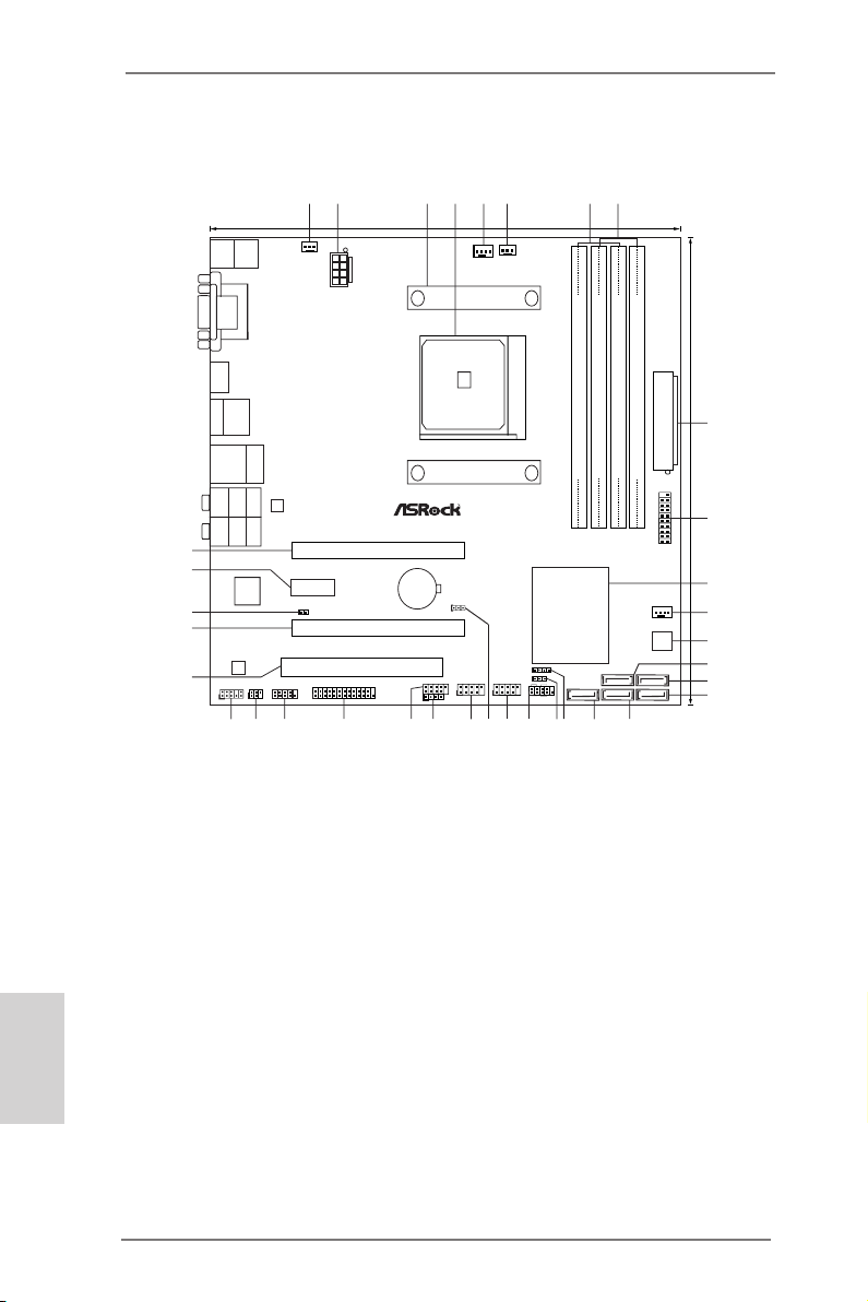
Motherboard Layout
SO CKE T FM 2
FM2A75 Pro4-M
AMD
A75 FCH
(Hudson-D3)
Chipset
CMOS
BATTERY
ATXP WR1
DDR3 _A1 (64 b it, 240 -pin mo dule)
DDR3 _A2 (64 b it, 240 -pin mo dule)
DDR3 _B1 (64 b it, 240 -pin mo dule)
DDR3 _B2 (64 b it, 240 -pin mo dule)
DDR3 2600+
64Mb
BIOS
24.4cm (9.6-in)
24. 4cm (9. 6-in)
Super
I/O
ATX12V1
PWR_FAN1
CPU_FAN1
CPU_FAN2
LAN
AUDIO
CODEC
1
CLRCMOS1
Front USB 3.0
SATA3_2
SATA3_5
SATA3_1
SATA3_4
HDLED RESET
PLED PWRBTN
1
PANEL1
CHA_FAN1
SPEAKER1
1
IR1
1
PLED1
1
COM1
1
CIR1
1
1
USB5_6
1
USB7_8
1
USB9_10
HD_AUDIO1
1
1
LPT1
PCIE1
PCIE3
PCI1
DX11
ErP/ EuP Read y
RoHS
USB 3.0
T: USB1
B: USB2
Ps2
Keyboard/
Mouse
HDMI 1
VGA 1
DVI_ CON1
USB 2.0
T: USB1
B: USB2
eSATA
Top:
RJ-45
USB 2.0
T: USB3
B: USB4
Top:
CTR BASS
Center:
REAR SPK
Bottom:
Optical
SPDIF
Top:
LINE IN
Center:
FRONT
Bottom:
MIC IN
Dual G raphi cs
Designed in Taipei
6
7
1
2
4
3
5
8
9
10
11
12
13
14
16
17
15
18
19
20
21
22
23
24
25
26
27
28
29
30
31
32
34
35
X
Fast USB
1
USB3_3_4
PCIE2
X
Fast RAM
X
Fast LAN
SATA3_3
CI1
1
33
English
1 Power Fan Connector (PWR_FAN1)
2
ATX 12V Power Connector (ATX12V1)
3 CPU Heatsink Retention Module
4 CPU Socket
5 CPU Fan Connector (CPU_FAN1)
6 CPU Fan Connector (CPU_FAN2)
7 2 x 240-pin DDR3 DIMM Slots
(DDR3_A1, DDR3_B1, Black)
8 2 x 240-pin DDR3 DIMM Slots
(DDR3_A2, DDR3_B2, Black)
9 ATX Power Connector (ATXPWR1)
10 USB 3.0 Header (USB3_3_4, Black)
11 Southbridge Controller
12
Chassis Fan Connector (CHA_FAN1)
13 SPI Flash Memory (64Mb)
14 SATA3 Connector (SATA3_5, Grey)
15 SATA3 Connector (SATA3_4, Grey)
16 SATA3 Connector (SATA3_1, Grey)
17 SATA3 Connector (SATA3_2, Grey)
2
18 SATA3 Connector (SATA3_3, Grey)
19
Chassis Speaker Header (SPEAKER1)
20 Power LED Header (PLED1)
21 System Panel Header (PANEL1)
22 USB 2.0 Header (USB5_6, Black)
23 Clear CMOS Jumper (CLRCMOS1)
24 USB 2.0 Header (USB7_8, Black)
25 Consumer Infrared Module Header
(CIR1, Gray)
26 USB 2.0 Header (USB9_10, Black)
27 Print Port Header (LPT1)
28 COM Port Header (COM1)
29 Infrared Module Header (IR1)
30
Front Panel Audio Header (HD_AUDIO1)
31 PCI Slot (PCI1)
32 PCI Express 2.0 x16 Slot (PCIE3)
33 Chassis Intrusion Header (CI1)
34 PCI Express 2.0 x1 Slot (PCIE2)
35 PCI Express 2.0 x16 Slot (PCIE1)
ASRock FM2A75 Pro4-M Motherboard
Page 3
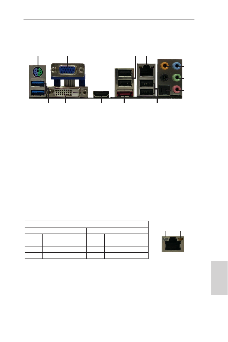
I/O Panel
10
1
2
3
4
5
8
6
9
7
15
14
1 PS/2 Mouse/Keyboard Port
(Green/Purple)
2 D-Sub Port (VGA)
3 USB 2.0 Ports (USB_1_2)
* 4 LAN RJ-45 Port
5 Central / Bass (Orange)
6 Rear Speaker (Black)
7 Optical SPDIF Out Port
* There are two LEDs on each LAN port. Please refer to the table below for the LAN
port LED indications.
13
12
8 Line In (Light Blue)
** 9 Front Speaker (Lime)
10 Microphone (Pink)
11 USB 2.0 Ports (USB_3_4)
*** 12 eSATA3 Connector
13 HDMI Port
14 DVI-D Port
15 USB 3.0 Ports (USB3_1_2)
11
LAN Port LED Indications
Activity/Link LED SPEED LED
Status Description Status Description
Off No Link Off 10Mbps connection
Blinking Data Activity Orange 100Mbps connection
On 100Mbps connection Green 1Gbps connection
ASRock FM2A75 Pro4-M Motherboard
ACT/LINK
LED
LAN Port
SPEED
LED
English
3
Page 4
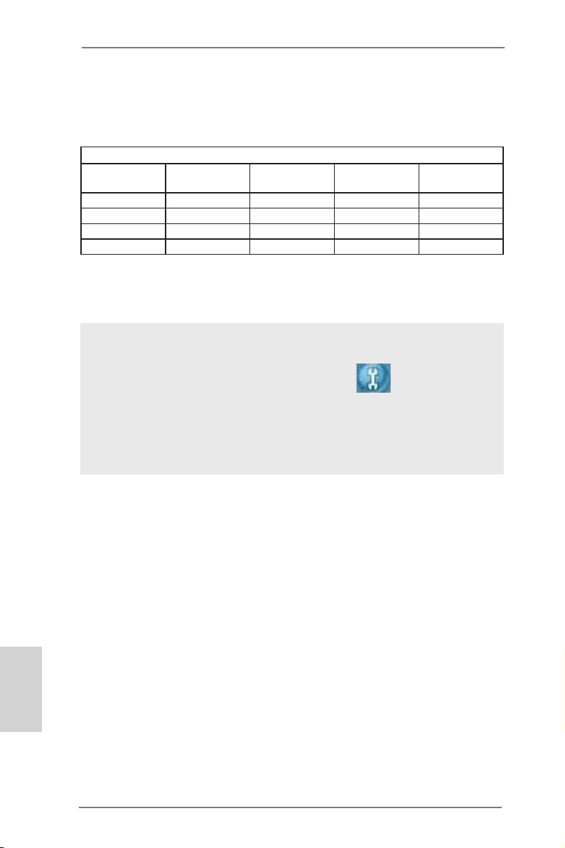
** If you use a 2-channel speaker, please connect the speaker’s plug into “Front
Speaker Jack”. See the table below for connection details in accordance with the
type of speaker you use.
TABLE for Audio Output Connection
Audio Output
Channels
2 V -- -- -4 V V -- -6 V V V -8 V V V V
To enable Multi-Streaming function, you need to connect a front panel audio cable
to the front panel audio header. After restarting your computer, you will nd “Mixer”
tool on your system. Please select “Mixer ToolBox” , click “Enable playback multi-streaming”, and click “ok”.
Choose “2CH”, “4CH”, “6CH”, or “8CH” and then you are allowed to select “Realtek
HDA Primary output” to use Rear Speaker, Central/Bass, and Front Speaker, or
select “Realtek HDA Audio 2nd output” to use front panel audio.
Front Speaker
(No. 9)
Rear Speaker
(No. 6)
Central / Bass
(No. 5)
Line In
(No. 8)
English
4
*** eSATA3 connector supports SATA Gen3 in cable 1M.
ASRock FM2A75 Pro4-M Motherboard
Page 5
1. Introduction
Thank you for purchasing ASRock FM2A75 Pro4-M motherboard, a reliable motherboard produced under ASRock’s consistently stringent quality
control. It delivers excellent performance with robust design conforming to
ASRock’s commitment to quality and endurance.
In this manual, chapter 1 and 2 contains the introduction of the motherboard and step-by-step hardware installation guide. Chapter 3 and 4 con-
tains the conguration guide of BIOS setup and information of the Support
CD.
Because the motherboard specications and the BIOS software
might be updated, the content of this manual will be subject to
change without notice. In case any modications of this manual
occur, the updated version will be available on ASRock’s web-
site without further notice. You may nd the latest VGA cards
and CPU support list on ASRock’s website as well. ASRock
website http://www.asrock.com
If you require technical support related to this motherboard,
please visit our website for specic information about the model
you are using.
www.asrock.com/support/index.asp
1.1 Package Contents
ASRock FM2A75 Pro4-M Motherboard
(Micro ATX Form Factor: 9.6-in x 9.6-in, 24.4 cm x 24.4 cm)
ASRock FM2A75 Pro4-M Quick Installation Guide
ASRock FM2A75 Pro4-M Support CD
2 x Serial ATA (SATA) Data Cables (Optional)
1 x I/O Panel Shield
ASRock FM2A75 Pro4-M Motherboard
English
5
Page 6
English
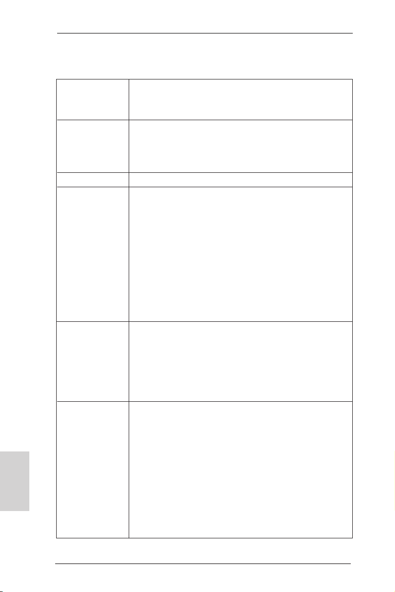
1.2 Specications
Platform - Micro ATX Form Factor: 9.6-in x 9.6-in, 24.4 cm x
24.4 cm
- All Solid Capacitor design
CPU - Support for Socket FM2 100W processors
- 4 + 2 Power Phase Design
- Supports AMD’s Cool ‘n’ QuietTM Technology
- UMI-Link GEN2
Chipset - AMD A75 FCH (Hudson-D3)
Memory - Dual Channel DDR3 Memory Technology
- 4 x DDR3 DIMM slots
- Support DDR3 2600+(OC)/2400(OC)/2133(OC)/1866/
1600/1333/1066/800 non-ECC, un-buffered memory
(see CAUTION 1)
- Max. capacity of system memory: 64GB
(see CAUTION 2)
- Supports Intel® Extreme Memory Prole (XMP) 1.3 /
1.2
- Supports AMD Memory Prole (AMP)
Expansion Slot - 2 x PCI Express 2.0 x16 slots (PCIE1 @ x16 mode;
PCIE3 @ x4 mode)
- 1 x PCI Express 2.0 x1 slot
- 1 x PCI slot
- Supports AMD Quad CrossFireXTM, CrossFireXTM and
Dual Graphics
Graphics - AMD Radeon HD 7000 series graphics
- DirectX 11, Pixel Shader 5.0
- Max. shared memory 2GB
- Three VGA Output options: D-Sub, DVI-D and HDMI
- Supports HDMI 1.4a Technology with max. resolution
up to 1920x1200 @ 60Hz
- Supports Dual-link DVI with max. resolution up to
2560x1600 @ 75Hz
- Supports D-Sub with max. resolution up to 1920x
1600 @ 60Hz
6
ASRock FM2A75 Pro4-M Motherboard
Page 7
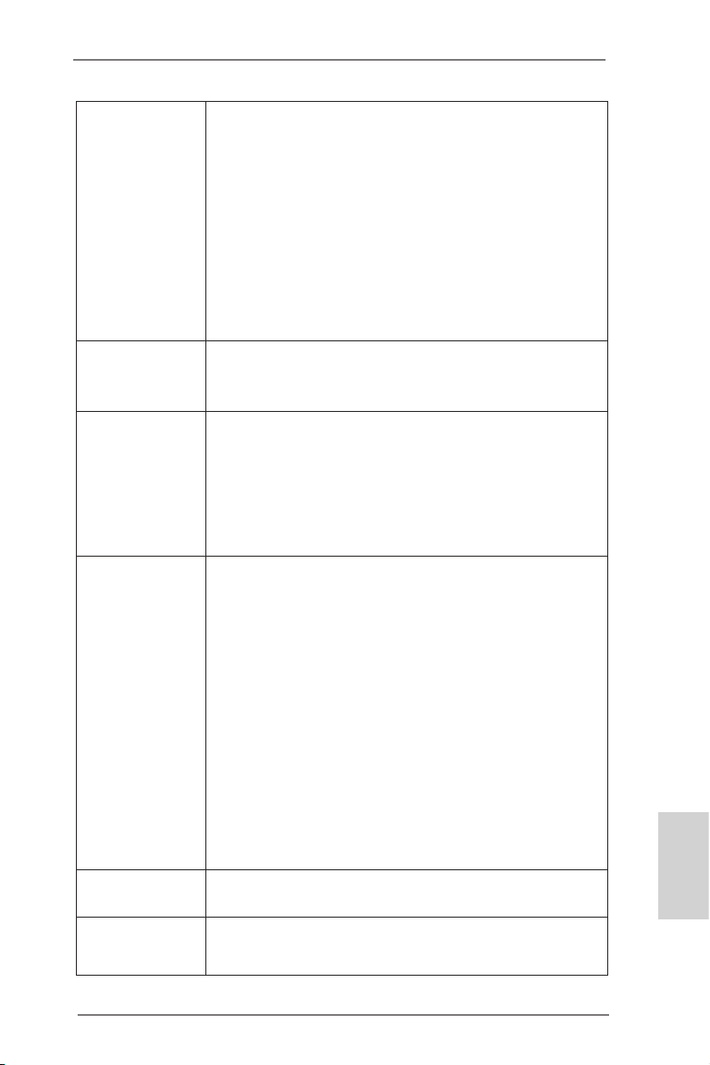
- Supports Auto Lip Sync, Deep Color (12bpc), xvYCC
and HBR (High Bit Rate Audio) with HDMI
(see CAUTION 3)
- Supports Blu-ray Stereoscopic 3D with HDMI 1.4a
- Supports AMD Steady VideoTM: New video post
processing capability for automatic jutter reduction on
home/online video
- Supports HDCP with DVI and HDMI ports
- Supports Full HD 1080p Blu-ray (BD) / HD-DVD
playback with DVI and HDMI ports
Audio - 7.1 CH HD Audio with Content Protection
(Realtek ALC892 Audio Codec)
- Premium Blu-ray audio support
LAN - PCIE x1 Gigabit LAN 10/100/1000 Mb/s
- Realtek RTL8111E
- Supports Wake-On-LAN
- Supports LAN Cable Detection
- Supports Energy Efcient Ethernet 802.3az
- Supports PXE
Rear Panel I/O I/O Panel
- 1 x PS/2 Mouse/Keyboard Port
- 1 x D-Sub Port
- 1 x DVI-D Port
- 1 x HDMI Port
- 1 x Optical SPDIF Out Port
- 4 x Ready-to-Use USB 2.0 Ports
- 1 x eSATA3 Connector
- 2 x Ready-to-Use USB 3.0 Ports
- 1 x RJ-45 LAN Port with LED (ACT/LINK LED and
SPEED LED)
- HD Audio Jack: Rear Speaker/Central/Bass/Line in/
Front Speaker/Microphone
SATA 3 - 5 x SATA3 6.0 Gb/s connectors, support RAID (RAID
0, RAID 1 and RAID 10), NCQ, AHCI and Hot Plug
USB 3.0
to 5Gb/s
- 2 x Rear USB 3.0 ports, support USB 1.1/2.0/3.0 up
English
ASRock FM2A75 Pro4-M Motherboard
7
Page 8
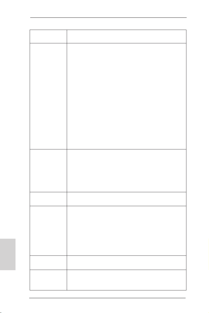
English
- 1 x Front USB 3.0 header (supports 2 USB 3.0 ports),
supports USB 1.1/2.0/3.0 up to 5Gb/s
Connector - 5 x SATA3 6.0Gb/s connectors
- 1 x IR header
- 1 x CIR header
- 1 x Print port header
- 1 x COM port header
- 1 x Power LED header
- 1 x Chassis Intrusion header
- 2 x CPU Fan connectors (1 x 4-pin, 1 x 3-pin)
- 1 x Chassis Fan connector (4-pin)
- 1 x Power Fan connector (3-pin)
- 24 pin ATX power connector
- 8 pin 12V power connector
- Front panel audio connector
- 3 x USB 2.0 headers (support 6 USB 2.0 ports)
- 1 x USB 3.0 header (supports 2 USB 3.0 ports)
BIOS Feature - 64Mb AMI UEFI Legal BIOS with GUI support
- Supports “Plug and Play”
- ACPI 1.1 Compliance Wake Up Events
- Supports jumperfree
- SMBIOS 2.3.1 Support
- DRAM, VDDP, VDDR, SB Voltage Multi-adjustment
Support CD - Drivers, Utilities, AntiVirus Software (Trial Version),
CyberLink MediaEspresso 6.5 Trial
Hardware - CPU Temperature Sensing
Monitor - Chassis Temperature Sensing
- CPU/Chassis/Power Fan Tachometer
- CPU/Chassis Quiet Fan
- CPU/Chassis Fan Multi-Speed Control
- CASE OPEN detection
- Voltage Monitoring: +12V, +5V, +3.3V, Vcore
OS - Microsoft® Windows® 7 / 7 64-bit / Vista
TM
/ VistaTM
64-bit / XP SP3 compliant
Certications - FCC, CE, WHQL
- ErP/EuP Ready (ErP/EuP ready power supply is
required)
8
ASRock FM2A75 Pro4-M Motherboard
Page 9

* For detailed product information, please visit our website:
http://www.asrock.com
WARNING
Please realize that there is a certain risk involved with
overclocking, including adjusting the setting in the BIOS,
applying Untied Overclocking Technology, or using thirdparty overclocking tools. Overclocking may affect your
system’s stability, or even cause damage to the components and devices of your system. It should be done at
your own risk and expense. We are not responsible for
possible damage caused by overclocking.
ASRock FM2A75 Pro4-M Motherboard
English
9
Page 10

CAUTION!
1. Whether 2600/2400/2133/1866/1600MHz memory speed
is supported depends on the CPU you adopt. If you want
to adopt DDR3 2600/2400/2133/1866/1600 memory
module on this motherboard, please refer to the memory
support list on our website for the compatible memory
modules.
ASRock website http://www.asrock.com
2. Due to the operating system limitation, the actual
memory size may be less than 4GB for the reservation
for system usage under Windows® 7 / VistaTM / XP. For
Windows® 64-bit OS with 64-bit CPU, there is no such
limitation. You can use ASRock XFast RAM to utilize the
memory that Windows® cannot use.
3. xvYCC and Deep Color are only supported under Windows® 7 64-bit / 7. Deep Color mode will be enabled only
if the display supports 12bpc in EDID. HBR is supported
under Windows® 7 64-bit / 7 / VistaTM 64-bit / VistaTM.
English
10
ASRock FM2A75 Pro4-M Motherboard
Page 11

1.3 Unique Features
ASRock Extreme Tuning Utility (AXTU)
ASRock Extreme Tuning Utility (AXTU) is an all-in-
one tool to ne-tune different system functions in a userfriendly interface, which includes Hardware Monitor, Fan
Control, Overclocking, OC DNA, IES and XFast RAM.
In Hardware Monitor, it shows the major readings of
your system. In Fan Control, it shows the fan speed and
temperature for you to adjust. In Overclocking, you are
allowed to overclock CPU frequency for optimal system
performance. In OC DNA, you can save your OC settings as a profile and share it with your friends. Your
friends then can load the OC prole to their own system
to get the same OC settings. In IES (Intelligent Energy
Saver), the voltage regulator can reduce the number of
output phases to improve efciency when the CPU cores
are idle without sacrificing computing performance. In
XFast RAM, it fully utilizes the memory space that cannot be used under Windows® OS 32-bit CPU.
ASRock Instant Boot
ASRock Instant Boot allows you to turn on your PC in
just a few seconds, provides a much more efcient way
to save energy, time, money, and improves system running speed for your system. It leverages the S3 and S4
ACPI features which normally enable the Sleep/Standby
and Hibernation modes in Windows® to shorten boot up
time. By calling S3 and S4 at specic timing during the
shutdown and startup process, Instant Boot allows you
to enter your Windows® desktop in a few seconds.
ASRock Instant Flash
ASRock Instant Flash is a BIOS ash utility embedded
in Flash ROM. This convenient BIOS update tool allows
you to update system BIOS without entering operating
systems rst like MS-DOS or Windows®. With this utility,
ASRock FM2A75 Pro4-M Motherboard
English
11
Page 12

you can press the <F6> key during the POST or the
<F2> key to enter into the BIOS setup menu to access
ASRock Instant Flash. Just launch this tool and save
the new BIOS le to your USB ash drive, oppy disk or
hard drive, then you can update your BIOS only in a few
clicks without preparing an additional oppy diskette or
other complicated ash utility. Please be noted that the
USB ash drive or hard drive must use FAT32/16/12 le
system.
ASRock APP Charger
If you desire a faster, less restricted way of charging your
Apple devices, such as iPhone/iPad/iPod Touch, ASRock
has prepared a wonderful solution for you - ASRock APP
Charger. Simply install the APP Charger driver, it makes
your iPhone charge much quickly from your computer
and up to 40% faster than before. ASRock APP Charger
allows you to quickly charge many Apple devices simultaneously and even supports continuous charging when
your PC enters into Standby mode (S1), Suspend to
RAM (S3), hibernation mode (S4) or power off (S5). With
APP Charger driver installed, you can easily enjoy the
marvelous charging experience.
English
12
ASRock XFast USB
ASRock XFast USB can boost USB storage device per-
formance. The performance may depend on the properties of the device.
ASRock XFast LAN
ASRock XFast LAN provides a faster internet access,
which includes the benets listed below. LAN Application
Prioritization: You can congure your application’s prior-
ity ideally and/or add new programs. Lower Latency in
Game: After setting online game’s priority higher, it can
lower the latency in games. Traffic Shaping: You can
watch Youtube HD videos and download simultaneously.
ASRock FM2A75 Pro4-M Motherboard
Page 13

Real-Time Analysis of Your Data: With the status win-
dow, you can easily recognize which data streams you
are transferring currently.
ASRock XFast RAM
ASRock XFast RAM is a new function that is included
into ASRock Extreme Tuning Utility (AXTU). It fully utilizes the memory space that cannot be used under Windows® OS 32-bit CPU. ASRock XFast RAM shortens the
loading time of previously visited websites, making web
surng faster than ever. And it also boosts the speed of
Adobe Photoshop 5 times faster. Another advantage of
ASRock XFast RAM is that it reduces the frequency of
accessing your SSDs or HDDs in order to extend their
lifespan.
ASRock Crashless BIOS
ASRock Crashless BIOS allows users to update their
BIOS without fear of failing. If power loss occurs during
the BIOS update process, ASRock Crashless BIOS will
automatically finish the BIOS update procedure after
regaining power. Please note that BIOS files need to
be placed in the root directory of your USB disk. Only
USB2.0 ports support this feature.
ASRock OMG (Online Management Guard)
Administrators are able to establish an internet curfew or
restrict internet access at specied times via OMG. You
may schedule the starting and ending hours of internet
access granted to other users. In order to prevent users
from bypassing OMG, guest accounts without permission
to modify the system time are required.
ASRock Internet Flash
ASRock Internet Flash searches for available UEFI rm-
ware updates from our servers. In other words, the system can auto-detect the latest UEFI from our servers
ASRock FM2A75 Pro4-M Motherboard
English
13
Page 14

and ash them without entering Windows® OS. Please
note that you must be running on a DHCP configured
computer in order to enable this function.
ASRock UEFI System Browser
ASRock UEFI system browser is a useful tool included in
graphical UEFI. It can detect the devices and congurations that users are currently using in their PC. With the
UEFI system browser, you can easily examine the cur-
rent system conguration in UEFI setup.
ASRock On/Off Play Technology
ASRock On/Off Play Technology allows users to enjoy
the great audio experience from the portable audio devices, such like MP3 player or mobile phone to your PC,
even when the PC is turned off (or in ACPI S5 mode)!
This motherboard also provides a free 3.5mm audio
cable (optional) that ensures users the most convenient
computing environment.
ASRock Dehumidier Function
Users may prevent motherboard damages due to damp-
ness by enabling “Dehumidifier Function”. When en-
abling Dehumidier Function, the computer will power on
automatically to dehumidify the system after entering S4/
S5 state.
English
14
ASRock Easy RAID Installer
ASRock Easy RAID Installer can help you to copy the
RAID driver from a support CD to your USB storage device. After copying the RAID driver to your USB storage
device, please change “SATA Mode” to “RAID”, then you
can start installing the OS in RAID mode.
ASRock Interactive UEFI
ASRock Interactive UEFI is a blend of system congura-
tion tools, cool sound effects and stunning visuals. The
ASRock FM2A75 Pro4-M Motherboard
Page 15

unprecedented UEFI provides a more attractive interface
and brings a lot more amusement.
ASRock FM2A75 Pro4-M Motherboard
English
15
Page 16

Chapter 2: Installation
This is a micro ATX form factor (9.6" x 9.6", 24.4 x 24.4 cm) motherboard.
Before you install the motherboard, study the conguration of your chassis
to ensure that the motherboard ts into it.
Pre-installation Precautions
Take note of the following precautions before you install motherboard components or change any motherboard settings.
1. Make sure to unplug the power cord before installing or
removing the motherboard. Failure to do so may cause
physical injuries to you and damages to motherboard components.
2. In order to avoid damage from static electricity to the motherboard’s components, NEVER place your motherboard
directly on a carpet. Also remember to use a grounded wrist
strap or touch a safety grounded object before you handle
the components.
3. Hold components by the edges and do not touch the ICs.
4. Whenever you uninstall any components, place them on a
grounded anti-static pad or in the bag that comes with the
components.
5. When placing screws to secure the motherboard to the
chassis, please do not over-tighten the screws! Doing so
may damage the motherboard.
English
16
ASRock FM2A75 Pro4-M Motherboard
Page 17
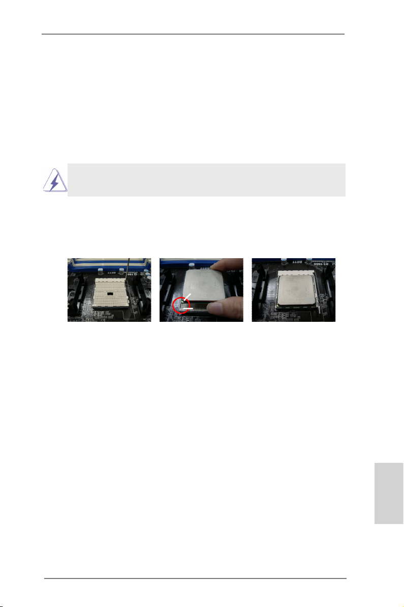
2.1 CPU Installation
o
Step 1. Unlock the socket by lifting the lever up to a 90
Step 2. Position the CPU directly above the socket so that the CPU corner
with the golden triangle matches the small triangle on the socket’s
corner.
Step 3. Carefully insert the CPU into the socket until it ts in place.
The CPU ts only in one correct orientation. DO NOT force
the CPU into the socket to avoid bending of the pins.
Step 4. When the CPU is in place, press it rmly on the socket while you
push down the socket lever to secure the CPU. The lever clicks
on the side tab to indicate that it is locked.
Lever 90° Up
CPU Golden Triangle
Socket Corner Small
Triangle
angle.
STEP 1:
Lift Up The Socket Lever
STEP 2 / STEP 3:
Match The CPU’s Golden
Triangle To The Small
Triangle on the Socket’s
Corner
STEP 4:
Push Down And Lock
The Socket Lever
2.2 Installation of CPU Fan and Heatsink
After you install the CPU into this motherboard, it is necessary
to install a compatible heatsink and cooling fan to dissipate heat.
You also need to spray thermal grease between the CPU and
the heatsink to improve heat dissipation. Make sure that the
CPU and the heatsink are securely fastened and in good contact with each other. Then connect the CPU fan to the CPU FAN
connector (CPU_FAN1, see Page 2, No. 5 or CPU_FAN2, see
Page 2, No. 6). For proper installation, please kindly refer to the
instruction manual of the CPU fan and the heatsink.
ASRock FM2A75 Pro4-M Motherboard
English
17
Page 18
2.3 Installation of Memory Modules (DIMM)
This motherboard provides four 240-pin DDR3 (Double Data Rate 3)
DIMM slots, and supports Dual Channel Memory Technology. For dual
channel conguration, you always need to install identical (the same
brand, speed, size and chip-type) DDR3 DIMM pairs. In other words,
you have to install identical DDR3 DIMM pairs in Dual Channel A
(DDR3_A1 and DDR3_B1, see p.2 No. 7) or identical DDR3 DIMM
pairs in Dual Channel B (DDR3_A2 and DDR3_B2, see p.2 No. 8), so
that Dual Channel Memory Technology can be activated. This motherboard also allows you to install four DDR3 DIMMs for dual channel
conguration, please install identical DDR3 DIMMs in all four slots.
You may refer to the Dual Channel Memory Conguration Table below.
Dual Channel Memory Congurations
DDR3_A1
(Blue Slot)
(1) Populated - Populated (2) - Populated - Populated
(3) Populated Populated Populated Populated
* For conguration (3), please install identical DDR3 DIMMs in all four
slots.
DDR3_A2
(White Slot)
DDR3_B1
(Blue Slot)
DDR3_B2
(White Slot)
English
18
1. If you want to install two memory modules, for optimal compatibility and reliability, it is recommended to install them in
DDR3_A1 and DDR3_B1 or in DDR3_A2 and DDR3_B2.
2. If only one memory module or three memory modules are
installed in the DDR3 DIMM slots on this motherboard, it is
unable to activate the Dual Channel Memory Technology.
3. If a pair of memory modules is NOT installed in the same
Dual Channel, for example, installing a pair of memory
modules in DDR3_A1 and DDR3_A2, it is unable to activate Dual Channel Memory Technology.
4. It is not allowed to install a DDR or DDR2 memory module
into a DDR3 slot; otherwise, this motherboard and DIMM
may be damaged.
ASRock FM2A75 Pro4-M Motherboard
Page 19
5. If you adopt DDR3 2600/2400/2133/1866/1600 memory
modules on this motherboard, it is recommended to install
them on DDR3_A2 and DDR3_B2 slots.
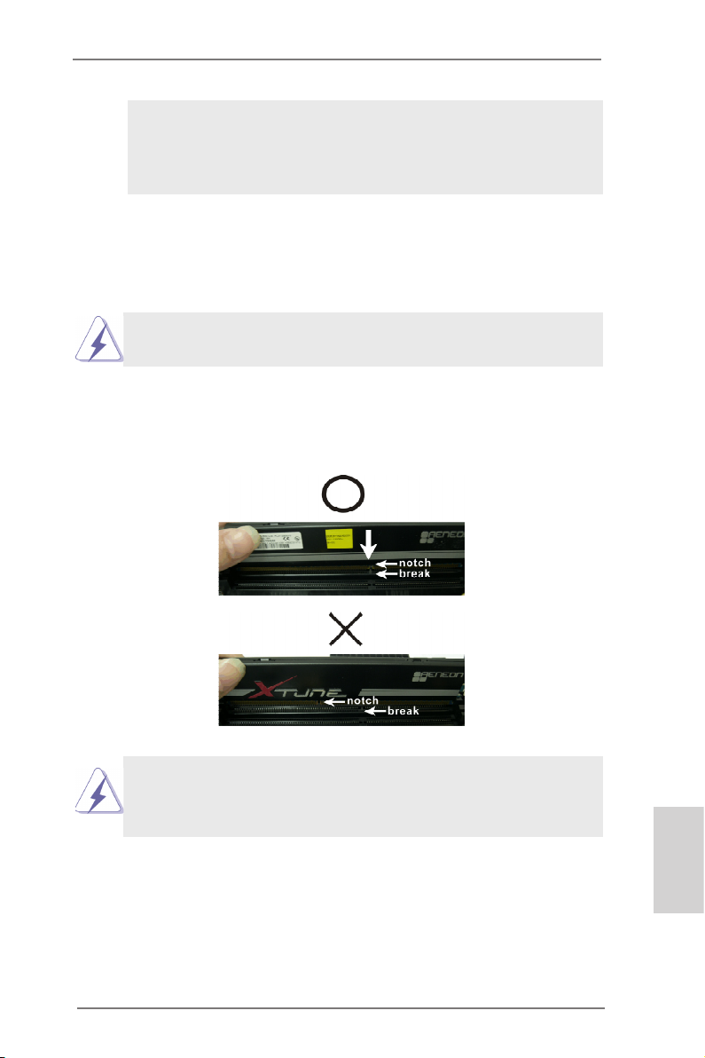
Installing a DIMM
Please make sure to disconnect the power supply before adding or removing DIMMs or system components.
Step 1. Unlock a DIMM slot by pressing the retaining clips outward.
Step 2. Align a DIMM on the slot such that the notch on the DIMM
matches the break on the slot.
The DIMM only ts in one correct orientation. It will cause permanent damage to the motherboard and the DIMM if you force
the DIMM into the slot at incorrect orientation.
Step 3. Firmly insert the DIMM into the slot until the retaining clips at both
ends fully snap back in place and the DIMM is properly seated.
ASRock FM2A75 Pro4-M Motherboard
English
19
Page 20
English
2.4 Expansion Slots (PCI and PCI Express Slots)
There is 1 PCI slot and 3 PCI Express slots on this motherboard.
PCI Slot: The PCI slot is used to install expansion cards that have 32-bit
PCI interface.
PCIE Slots: PCIE1 (PCIE x16 slot) is used for PCI Express x16 lane width
graphics cards, or used to install PCI Express graphics cards to
support CrossFireXTM function.
PCIE2 (PCIE x1 slot) is used for PCI Express cards with x1 lane
width. Such as Gigabit LAN card or SATA2 cards, etc.
PCIE3 (PCIE x16 slot) is used for PCI Express x4 lane width
cards, or used to install PCI Express graphics cards to support
CrossFireXTM function.
1. In single VGA card mode, it is recommended to install a
PCI Express x16 graphics card on PCIE1 slot.
2. In CrossFireXTM mode, please install PCI Express x16
graphics cards on PCIE1 and PCIE3 slots.
Installing an expansion card
Step 1. Before installing the expansion card, please make sure that the
power supply is switched off and the power cord is unplugged.
Please read the documentation of the expansion card and make
necessary hardware settings for the card before you start the
installation.
Step 2. Remove the system unit cover (if your motherboard is already
installed in a chassis).
Step 3. Remove the bracket facing the slot that you intend to use. Keep
the screws for later use.
Step 4. Align the card connector with the slot and press rmly until the
card is completely seated on the slot.
Step 5. Fasten the card to the chassis with screws.
Step 6. Replace the system cover.
20
ASRock FM2A75 Pro4-M Motherboard
Page 21
2.5 CrossFireXTM and Quad CrossFireXTM Operation Guide
This motherboard supports CrossFireXTM and Quad CrossFireXTM.
CrossFireXTM technology offers the most advantageous means available
of combining multiple high performance Graphics Processing Units (GPU)
in a single PC. Combining a range of different operating modes with
intelligent software design and an innovative interconnect mechanism,
CrossFireXTM enables the highest possible level of performance and image
quality in any 3D application. Currently CrossFireXTM feature is supported
with Windows® XP with Service Pack 2 / VistaTM / 7 OS. Quad CrossFireX
feature are supported with Windows® VistaTM / 7 OS only. Please check
AMD website for AMD CrossFireXTM driver updates.
1. If a customer incorrectly congures their system they will not see
the performance benefits of CrossFireXTM. All three CrossFireXTM
components, a CrossFireXTM Ready graphics card, a CrossFireXTM
Ready motherboard and a CrossFireXTM Edition co-processor
graphics card, must be installed correctly to benefit from the
CrossFireXTM multi-GPU platform.
2. If you pair a 12-pipe CrossFireXTM Edition card with a 16-pipe card,
both cards will operate as 12-pipe cards while in CrossFireXTM
mode.
TM
2.5.1 Graphics Card Setup
Different CrossFireXTM cards may require different methods to enable
CrossFireXTM feature. For other CrossFireXTM cards that AMD has released or will release in the future, please refer to AMD graphics card
manuals for detailed installation guide.
Step 1. Insert one Radeon graphics card into PCIE1 slot and the other
Radeon graphics card to PCIE3 slot. Make sure that the cards are
properly seated on the slots.
ASRock FM2A75 Pro4-M Motherboard
English
21
Page 22
English
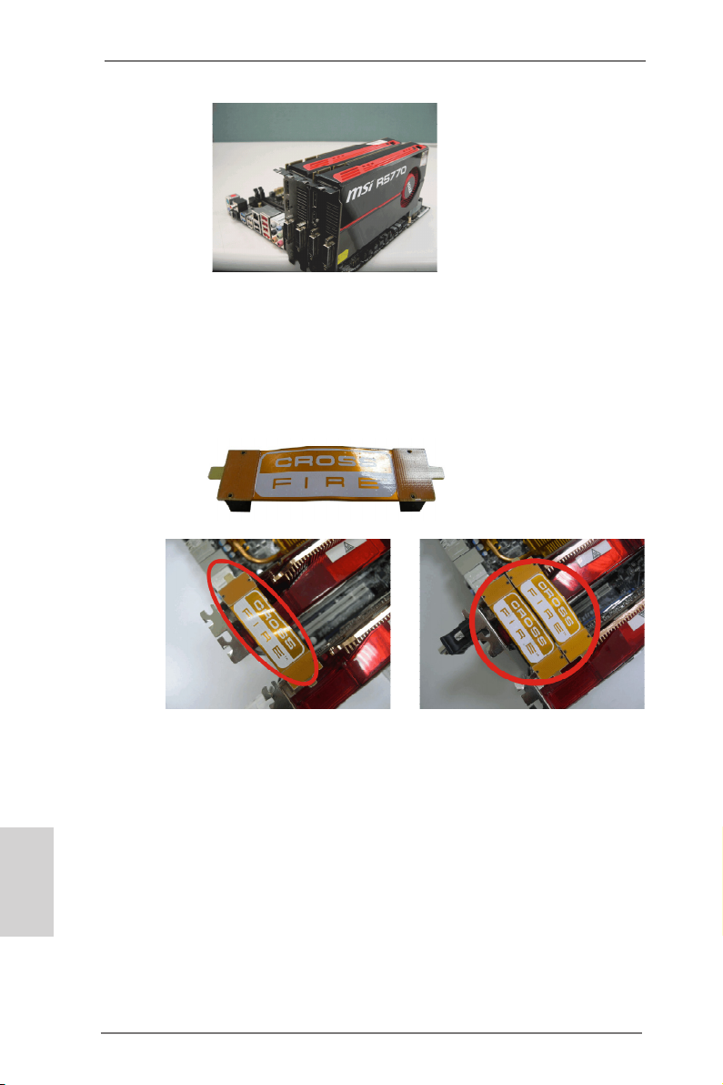
Step 2. Connect two Radeon graphics cards by installing a CrossFire
Bridge on the top of the Radeon graphics cards. (The CrossFire Bridge is provided with the graphics card you purchase, not
bundled with this motherboard. Please refer to your graphics card
vendor for details.)
CrossFire Bridge
or
Step 3. Connect the DVI monitor cable to the DVI connector on the Rad-
eon graphics card on PCIE1 slot. (You may use the DVI to D-Sub
adapter to convert the DVI connector to D-Sub interface, and then
connect the D-Sub monitor cable to the DVI to D-Sub adapter.)
22
ASRock FM2A75 Pro4-M Motherboard
Page 23
2.5.2 Driver Installation and Setup
Step 1. Power on your computer and boot into OS.
Step 2. Remove the AMD driver if you have any VGA driver installed in
your system.
The Catalyst Uninstaller is an optional download. We recommend using
this utility to uninstall any previously installed Catalyst drivers prior to installation. Please check AMD’s website for AMD driver updates.
Step 3. Install the required drivers to your system.
For Windows® XP OS:
A. AMD recommends Windows® XP Service Pack 2 or higher to
be installed (If you have Windows® XP Service Pack 2 or higher
installed in your system, there is no need to download it again):
http://www.microsoft.com/windowsxp/sp2/default.mspx
B. You must have Microsoft .NET Framework installed prior to
downloading and installing the CATALYST Control Center.
Please check Microsoft website for details.
For Windows® 7 / VistaTM OS:
Install the CATALYST Control Center. Please check AMD’s web-
site for details.
Step 4. Restart your computer.
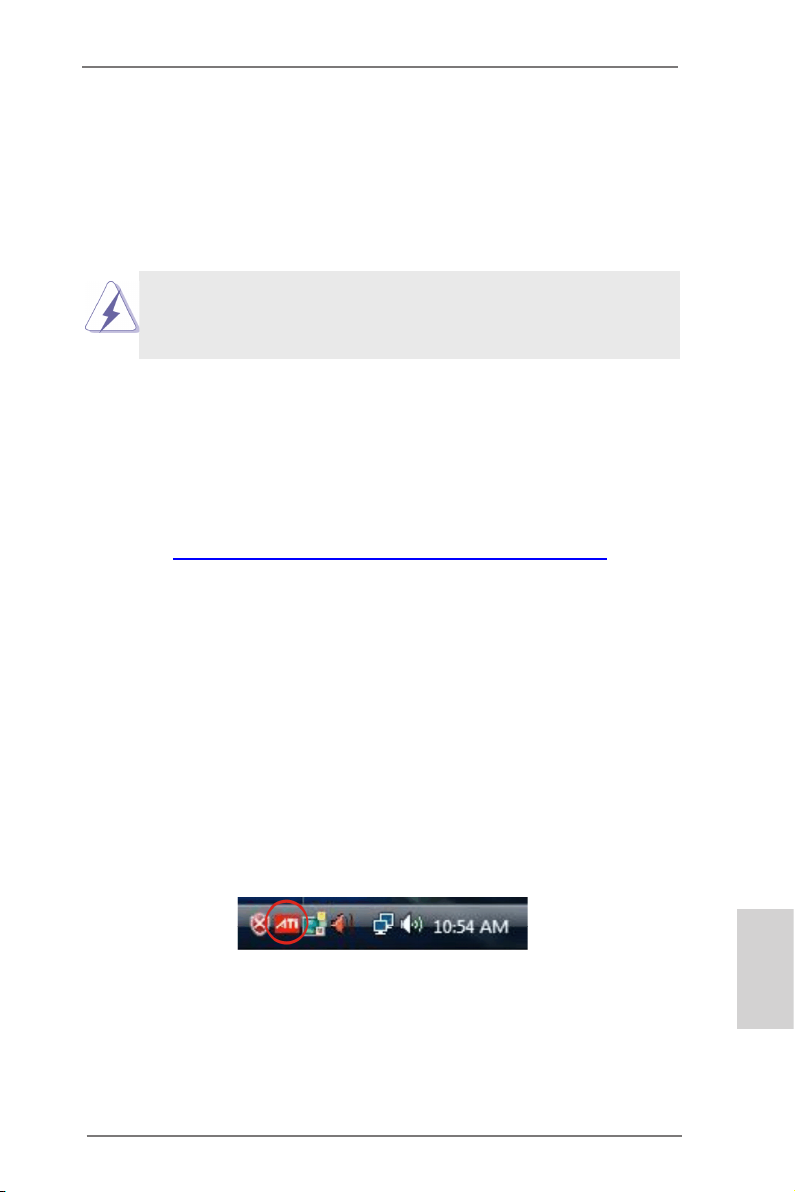
Step 5. Install the VGA card drivers to your system, and restart your com-
puter. Then you will nd “AMD Catalyst Control Center” on your
Windows® taskbar.
AMD Catalyst Control Center
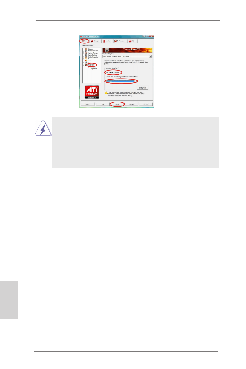
Step 6. Double-click “AMD Catalyst Control Center”. Click “View”, select
“CrossFireXTM”, and then check the item “Enable CrossFireXTM”.
Select “2 GPUs” and click “Apply” (if you install two Radeon
graphics cards).
ASRock FM2A75 Pro4-M Motherboard
English
23
Page 24
English
Although you have selected the option “Enable CrossFireTM”, the Cross-
FireXTM function may not work actually. Your computer will automatically
reboot. After restarting your computer, please conrm whether the option
“Enable CrossFireTM” in “AMD Catalyst Control Center” is selected or not;
if not, please select it again, and then you are able to enjoy the benet of
CrossFireX
TM
feature.
Step 7. You can freely enjoy the benet of CrossFireXTM or Quad CrossFi-
reXTM feature.
* CrossFireXTM appearing here is a registered trademark of AMD Technologies Inc.,
and is used only for identication or explanation and to the owners’ benet,
without intent to infringe.
* For further information of AMD CrossFireXTM technology, please check AMD’s
website for updates and details.
24
ASRock FM2A75 Pro4-M Motherboard
Page 25
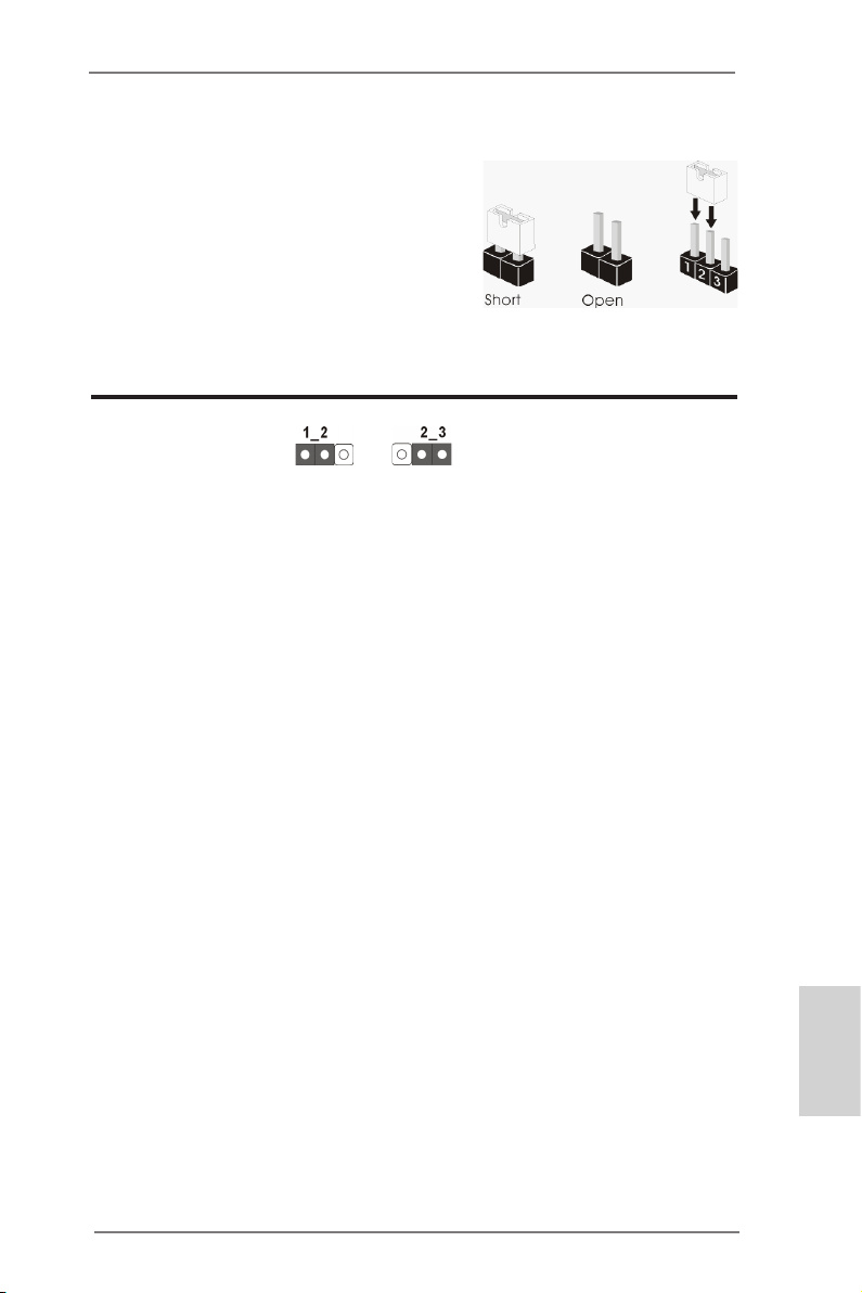
2.6 Jumpers Setup
The illustration shows how jumpers are
setup. When the jumper cap is placed on
pins, the jumper is “Short”. If no jumper cap
is placed on pins, the jumper is “Open”. The
illustration shows a 3-pin jumper whose
pin1 and pin2 are “Short” when jumper cap
is placed on these 2 pins.
Clear CMOS Jumper
(CLRCMOS1)
(see p.2, No. 23)
CLRCMOS1 allows you to clear the data in CMOS. To clear and reset
the system parameters to default setup, please turn off the computer and
unplug the power cord from the power supply. After waiting for 15 seconds,
use a jumper cap to short pin2 and pin3 on CLRCMOS1 for 5 seconds.
However, please do not clear the CMOS right after you update the BIOS.
If you need to clear the CMOS when you just nish updating the BIOS,
you must boot up the system rst, and then shut it down before you do the
clear-CMOS action. Please be noted that the password, date, time, user
default prole, 1394 GUID and MAC address will be cleared only if the
CMOS battery is removed.
Clear CMOSDefault
ASRock FM2A75 Pro4-M Motherboard
English
25
Page 26
2.7 Onboard Headers and Connectors
Onboard headers and connectors are NOT jumpers. Do NOT
place jumper caps over these headers and connectors. Placing jumper caps over the headers and connectors will cause
permanent damage to the motherboard!
English
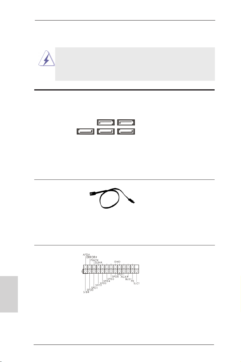
Serial ATA3 Connectors
(SATA3_1:
see p.2, No. 16)
(SATA3_2:
see p.2, No. 17)
(SATA3_3:
see p.2, No. 18)
(SATA3_4:
see p.2, No. 15)
(SATA3_5:
see p.2, No. 14)
SATA3_3 SATA3_2 SATA3_1
Serial ATA (SATA)
Data Cable
(Optional)
Print Port Header
(25-pin LPT1)
(see p.2, No. 27)
SATA3_5 SATA3_4
These ve Serial ATA3
(SATA3) connectors support SATA data cables for
internal storage devices.
The current SATA3 interface
allows up to 6.0 Gb/s data
transfer rate.
Either end of the SATA data
cable can be connected to
SATA / SATA2 / SATA3 hard
disks or the SATA2 / SATA3
connectors on this motherboard.
This is an interface for print
port cables that allows convenient connection of printer
devices.
26
ASRock FM2A75 Pro4-M Motherboard
Page 27
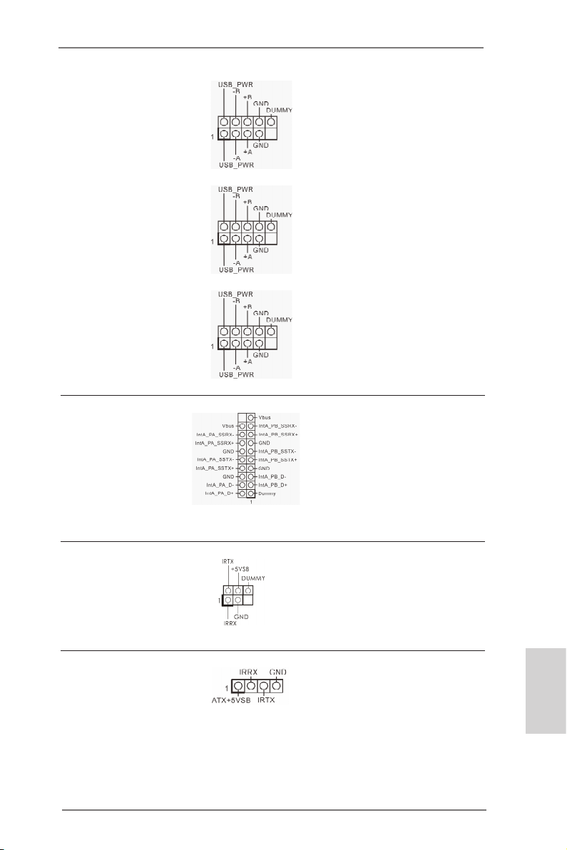
USB 2.0 Headers
and Ports
(9-pin USB5_6)
(see p.2, No. 22)
(9-pin USB7_8)
(see p.2, No. 24)
(9-pin USB9_10)
(see p.2, No. 26)
Besides four default USB 2.0
ports on the I/O panel, there
are three USB 2.0 headers
on this motherboard. Each
USB 2.0 header can support
two USB 2.0 ports.
USB 3.0 Header
(19-pin USB3_3_4)
(see p.2, No. 10)
Infrared Module Header
(5-pin IR1)
(see p.2, No. 29)
Consumer Infrared
Module Header
(4-pin CIR1)
(see p.2, No. 25)
ASRock FM2A75 Pro4-M Motherboard
Besides two default USB 3.0
ports on the I/O panel, there
is one USB 3.0 header on
this motherboard. Each USB
3.0 header can support two
USB 3.0 ports.
This header supports an
optional wireless transmitting and receiving infrared
module.
This header can be used
to connect the remote
controller receiver.
English
27
Page 28
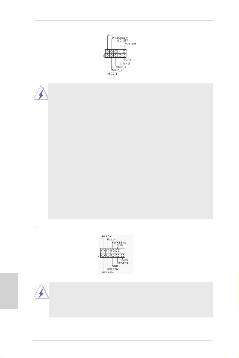
Front Panel Audio Header
(9-pin HD_AUDIO1)
(see p.2, No. 30)
1. High Denition Audio supports Jack Sensing, but the panel
wire on the chassis must support HDA to function correctly.
Please follow the instructions in our manual and chassis
manual to install your system.
2. If you use an AC’97 audio panel, please install it to the front
panel audio header by the steps below:
A. Connect Mic_IN (MIC) to MIC2_L.
B. Connect Audio_R (RIN) to OUT2_R and Audio_L (LIN) to
OUT2_L.
C. Connect Ground (GND) to Ground (GND).
D. MIC_RET and OUT_RET are for HD audio panel only. You
don’t need to connect them for AC’97 audio panel.
E. To activate the front mic.
For Windows® XP OS:
Select “Mixer”. Select “Recorder”. Then click “FrontMic”.
For Windows® 7 / 7 64-bit / VistaTM / VistaTM 64-bit OS:
Go to the "FrontMic" Tab in the Realtek Control panel.
Adjust “Recording Volume”.
This is an interface for the
front panel audio cable that
allows convenient connection and control of audio
devices.
English
28
System Panel Header
(9-pin PANEL1)
(see p.2, No. 21)
Connect the power switch, reset switch and system status indica-
tor on the chassis to this header according to the pin assignments
below. Note the positive and negative pins before connecting the
cables.
ASRock FM2A75 Pro4-M Motherboard
This header accommodates
several system front panel
functions.
Page 29
PWRBTN (Power Switch):
Connect to the power switch on the chassis front panel. You may
congure the way to turn off your system using the power switch.
RESET (Reset Switch):
Connect to the reset switch on the chassis front panel. Press the
reset switch to restart the computer if the computer freezes and
fails to perform a normal restart.
PLED (System Power LED):
Connect to the power status indicator on the chassis front panel.
The LED is on when the system is operating. The LED keeps
blinking when the sys-tem is in S1/S3 sleep state. The LED is off
when the system is in S4 sleep state or powered off (S5).
HDLED (Hard Drive Activity LED):
Connect to the hard drive activity LED on the chassis front panel.
The LED is on when the hard drive is reading or writing data.
The front panel design may differ by chassis. A front panel mod-
ule mainly consists of power switch, reset switch, power LED,
hard drive activity LED, speaker and etc. When connecting your
chassis front panel module to this header, make sure the wire as-
signments and the pin assignments are matched correctly.
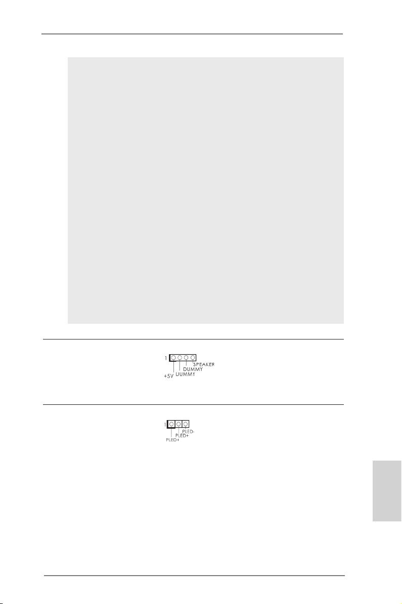
Chassis Speaker Header
(4-pin SPEAKER1)
(see p.2, No. 19)
Power LED Header
(3-pin PLED1)
(see p.2, No. 20)
ASRock FM2A75 Pro4-M Motherboard
Please connect the chassis
speaker to this header.
Please connect the chassis
power LED to this header
to indicate system power
status. The LED is on when
the system is operating. The
LED keeps blinking in S1
state. The LED is off in S3/
S4 state or S5 state (power
off).
English
29
Page 30
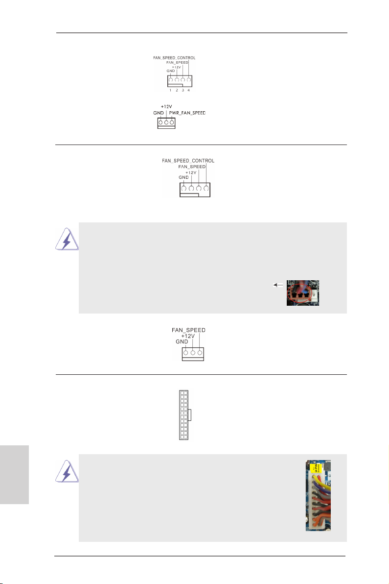
Chassis and Power
Fan Connectors
(4-pin CHA_FAN1)
(see p.2, No. 12)
(4-pin PWR_FAN1)
(see p.2, No. 1)
Please connect the fan
cables to the fan connectors
and match the black wire to
the ground pin.
CPU Fan Connectors
(4-pin CPU_FAN1)
(see p.2, No. 5)
Though this motherboard provides a 4-Pin CPU fan (Quiet Fan)
connector, 3-Pin CPU fans can still work successfully even without the fan speed control function. If you plan to connect a 3-Pin
CPU fan to the CPU fan connector on this motherboard, please
connect it to Pin 1-3.
(3-pin CPU_FAN2)
(see p.2, No. 6)
ATX Power Connector
(24-pin ATXPWR1)
(see p.2, No. 9)
12 124
Pin 1-3 Connected
3-Pin Fan Installation
13
Please connect the CPU fan
cable to the connector and
match the black wire to the
ground pin.
Please connect an ATX power supply to this connector.
English
30
Though this motherboard provides a 24-pin ATX
power connector, it can still work if you adopt a
traditional 20-pin ATX power supply. To use a 20pin ATX power supply, please plug your power
supply along Pin 1 and Pin 13.
20-Pin ATX Power Supply Installation
ASRock FM2A75 Pro4-M Motherboard
12
1
24
13
Page 31

ATX 12V Power
Connector
(8-pin ATX12V1)
(see p.2, No. 2)
Though this motherboard provides an 8-pin ATX 12V power con-
nector, it can still work if you adopt a traditional 4-pin ATX 12V
power supply. To use a 4-pin ATX power supply, please plug your
power supply along Pin 1 and Pin 5.
Please connect an ATX 12V
power supply to this connector.
4 8
Serial port Header
(9-pin COM1)
(see p.2, No. 28)
Chassis Intrusion Header
(2-pin CI1)
(see p.2, No. 33)
4-Pin ATX 12V Power Supply Installation
This COM1 header supports
a serial port module.
This motherboard supports
CASE OPEN detection
which detects whether the
chassis cover has been removed. This feature requires
a chassis with chassis intrusion detection design.
1 5
ASRock FM2A75 Pro4-M Motherboard
English
31
Page 32

2.8 Driver Installation Guide
To install the drivers to your system, please insert the support CD into your
optical drive rst. Then, the drivers compatible to your system can be auto-
detected and listed on the support CD driver page. Please follow the order
from top to bottom to install those required drivers. Therefore, the drivers
you install can work properly.
English
2.9 Installing Windows® 7 / 7 64-bit / Vista
TM
/ VistaTM 64-bit
With RAID
If you want to install Windows® 7 / 7 64-bit / VistaTM / VistaTM 64-bit on your
SATA3 HDDs with RAID, please refer to the document at the following path
in the Support CD for detailed procedures: ..\ RAID Installation Guide
2.10 Installing Windows® 7 / 7 64-bit / Vista
TM
/ Vista
TM
64-bit /
XP Without RAID
If you want to install Windows® 7 / 7 64-bit / VistaTM / VistaTM 64-bit / XP OS
on your SATA3 HDDs without RAID, please follow the procedures below
according to the OS you install.
2.10.1 Installing Windows® XP Without RAID
If you want to install Windows® XP OS on your SATA3 HDDs without RAID,
please follow the steps below.
Using SATA3 HDDs without NCQ
STEP 1: Set Up UEFI.
A. Enter UEFI SETUP UTILITY Advanced screen Storage
Conguration.
B. Set the option “SATA Mode” to [IDE].
STEP 2: Install Windows® XP OS on your system.
32
ASRock FM2A75 Pro4-M Motherboard
Page 33

2.10.2 Installing Windows® 7 / 7 64-bit / Vista
TM
/ Vista
TM
64-bit
Without RAID
If you want to install Windows® 7 / 7 64-bit / VistaTM / VistaTM 64-bit OS on
your SATA3 HDDs without RAID, please follow the steps below.
Using SATA3 HDDs with NCQ
STEP 1: Set Up UEFI.
A. Enter UEFI SETUP UTILITY Advanced screen Storage
Conguration.
B. Set the option “SATA Mode” to [AHCI].
STEP 2: Install Windows® 7 / 7 64-bit / VistaTM / VistaTM 64-bit OS on
your system.
Using SATA / SATA2 / SATA3 HDDs without NCQ
STEP 1: Set Up UEFI.
A. Enter UEFI SETUP UTILITY Advanced screen Storage
Conguration.
B. Set the option “SATA Mode” to [IDE].
STEP 2: Install Windows® 7 / 7 64-bit / VistaTM / VistaTM 64-bit OS on
your system.
ASRock FM2A75 Pro4-M Motherboard
English
33
Page 34

3. BIOS Information
The Flash Memory on the motherboard stores the BIOS Setup Utility.
When you start up the computer, please press <F2> or <Del> during the
Power-On-Self-Test (POST) to enter the BIOS Setup utility; otherwise,
POST continues with its test routines. If you wish to enter BIOS Setup after
POST, please restart the system by pressing <Ctl> + <Alt> + <Delete>, or
pressing the reset button on the system chassis. The BIOS Setup program
is designed to be user-friendly. It is a menu-driven program, which allows
you to scroll through its various sub-menus and to select among the predetermined choices. For detailed information about BIOS Setup, please refer
to the User Manual (PDF le) contained in the Support CD.
4. Software Support CD information
English
This motherboard supports various Microsoft® Windows® operating systems: 7 / 7 64-bit / VistaTM / Vista
with the motherboard contains necessary drivers and useful utilities that
will enhance motherboard features. To begin using the Support CD, insert
the CD into your CD-ROM drive. It will display the Main Menu automatically if “AUTORUN” is enabled in your computer. If the Main Menu does not
appear automatically, locate and double-click the le “ASRSETUP.EXE” in
the Support CD to display the menu.
TM
64-bit / XP. The Support CD that came
34
ASRock FM2A75 Pro4-M Motherboard
Page 35

1. Einführung
Wir danken Ihnen für den Kauf des ASRock FM2A75 Pro4-M Motherboard, ein zuverlässiges Produkt, welches unter den ständigen, strengen Qualitätskontrollen von
ASRock gefertigt wurde. Es bietet Ihnen exzellente Leistung und robustes Design,
gemäß der Verpflichtung von ASRock zu Qualität und Halbarkeit. Diese Schnellinstallationsanleitung führt in das Motherboard und die schrittweise Installation
ein. Details über das Motherboard nden Sie in der Bedienungsanleitung auf der
Support-CD.
Da sich Motherboard-Spezikationen und BIOS-Software verändern können,
kann der Inhalt dieses Handbuches ebenfalls jederzeit geändert werden. Für
den Fall, dass sich Änderungen an diesem Handbuch ergeben, wird eine neue
Version auf der ASRock-Website, ohne weitere Ankündigung, verfügbar sein.
Die neuesten Grakkarten und unterstützten CPUs sind auch auf der ASRock-
Website aufgelistet.
ASRock-Website: http://www.asrock.com
Wenn Sie technische Unterstützung zu Ihrem Motherboard oder spezische
Informationen zu Ihrem Modell benötigen, besuchen Sie bitte unsere Webseite:
www.asrock.com/support/index.asp
1.1 Kartoninhalt
ASRock FM2A75 Pro4-M Motherboard
(Micro ATX-Formfaktor: 24.4 cm x 24.4 cm; 9.6 Zoll x 9.6 Zoll)
ASRock FM2A75 Pro4-M Schnellinstallationsanleitung
ASRock FM2A75 Pro4-M Support-CD
Zwei Serial ATA (SATA) -Datenkabel (optional)
Ein I/O Shield
ASRock FM2A75 Pro4-M Motherboard
Deutsch
35
Page 36

Deutsch
1.2 Spezikationen
Plattform - Micro ATX-Formfaktor: 24.4 cm x 24.4 cm; 9.6 Zoll x 9.6 Zoll
- Alle Feste Kondensatordesign
CPU - Unterstützt Sockel-FM2-100-W-Prozessoren
- 4 + 2-Stromphasendesign
- Unterstützt Cool ‘n’ QuietTM-Technologie von AMD
- UMI-Link-GEN2
Chipsatz - AMD A75 FCH (Hudson-D3)
Speicher - Unterstützung von Dual-Kanal-Speichertechnologie
- 4 x Steckplätze für DDR3
- Unterstützt DDR3 2600+(OC)/2400(OC)/2133(OC)/1866/
1600/1333/1066/800 non-ECC, ungepufferter Speicher
- Max. Kapazität des Systemspeichers: 64GB
- Unterstützt Intel® Extreme Memory Prole (XMP)1.3/1.2
- Unterstützt AMD Memory Prole (AMP)
Erweiterungs- - 2 x PCI-Express-2.0-x16-Steckplätze (PCIE1: x16-Modus;
steckplätze PCIE3: x4-Modus)
- 1 x PCI-Express-2.0-x1-Steckplätze
- 1 x PCI -Steckplätze
- Unterstützt AMD Quad CrossFireXTM, CrossFireXTM und
duale Grakkarten
Onboard-VGA - AMD Radeon HD 7000-Grak
- DirectX 11, Pixel Shader 5.0
- Maximal gemeinsam genutzter Speicher 2GB
- Drei VGA-Ausgangsoptionen: D-Sub, DVI-D sowie HDMI
- Unterstützt HDMI 1.4a mit einer maximalen Auösung von
1920 x 1200 bei 60 Hz
- Unterstützt Dual-link DVI mit einer maximalen Auösung von
2560 x 1600 bei 75 Hz
- Unterstützt D-Sub mit einer maximalen Auösung von 1920
x 1600 bei 60 Hz
- Unterstützt Auto Lip Sync, Deep Color (12bpc), xvYCC und
HBR (High Bit Rate-Audio) mit HDMI
- Unterstützt stereoskopisches 3D per Blu-ray mit HDMI 1.4a
- Unterstützt AMD Steady VideoTM: Neuartige Funktion der
Videonachbearbeitung für automatische Reduzierung von
Bildschwankungen bei Heim-/Online-Videos
- Unterstützt HDCP mit DVI- und HDMI-Ports
- Unterstutzt 1080p Blu-ray (BD) / HD-DVD-Wiedergabe mit
DVI- und HDMI-Ports
36
ASRock FM2A75 Pro4-M Motherboard
Page 37

Audio - 7.1 CH HD Audio mit dem Inhalt Schutz
(Realtek ALC892 Audio Codec)
- Premium Blu-ray-Audio-Unterstützung
LAN - PCIE x1 Gigabit LAN 10/100/1000 Mb/s
- Realtek RTL8111E
- Unterstützt Wake-On-LAN
- Unterstützt LAN-Kabelerkennung
- Unterstützt energieefzientes Ethernet 802.3az
- Unterstützt PXE
E/A-Anschlüsse I/O Panel
an der - 1 x PS/2-Maus/Tastaturanschluss
Rückseite - 1 x D-Sub port
- 1 x DVI-D port
- 1 x HDMI port
- 1 x Optischer SPDIF-Ausgang
- 4 x Standard-USB 2.0-Anschlüsse
- 1 x eSATA3-Anschluss
- 2 x Standard-USB 3.0-Anschlüsse
- 1 x RJ-45 LAN Port mit LED (ACT/LINK LED und SPEED
LED)
- HD Audiobuchse: Lautsprecher hinten / Mitte/Bass /
Audioeingang / Lautsprecher vorne / Mikrofon
SATA3 - 5 x SATA 3-Anschluss mit 6,0 Gb/s, unterstützt RAID- (RAID
0, RAID 1 und RAID 10), NCQ-, AHCI- und Hot Plug
USB3.0 - 2 x USB 3.0-Ports an der Rückseite, unterstützt USB
1.1/2.0/3.0 mit bis zu 5 Gb/s
- 1 x USB 3.0-Header (unterstützt zwei USB 3.0-Ports) an der
Vorderseite, unterstützt USB 1.1/2.0/3.0 mit bis zu 5 Gb/s
Anschlüsse - 5 x SATA3 6,0 GB/s-Anschlüsse
- 1 x Infrarot-Modul-Header
- 1 x Consumer Infrarot-Modul-Header
- 1 x Druckerport-Anschlussleiste
- 1 x COM-Anschluss-Header
- 1 x Betriebs-LED-Header
- 1 x Verteiler für Gehäuse Eindringversuche
- 2 x CPUlüfter-Anschluss (1 x 4-pin, 1 x 3-pin)
- 1 x Gehäuselüfter-Anschluss (4-pin)
- 1 x Stromlüfter-Anschluss (3-pin)
- 24-pin ATX-Netz-Header
- 8-pin anschluss für 12V-ATX-Netzteil
Deutsch
ASRock FM2A75 Pro4-M Motherboard
37
Page 38

- Anschluss für Audio auf der Gehäusevorderseite
- 3 x USB 2.0-Anschlüsse (Unterstützung 6 zusätzlicher
USB 2.0-Anschlüsse)
- 1 x USB 3.0-Anschlüsse (Unterstützung 2 zusätzlicher
USB 3.0-Anschlüsse)
BIOS - 64Mb AMIs Legal BIOS UEFI mit GUI-Unterstützung
- Unterstützung für “Plug and Play”
- ACPI 1.1-Weckfunktionen
- JumperFree-Modus
- SMBIOS 2.3.1
- DRAM, VDDP, VDDR, SB Stromspannung Multianpassung
Support-CD - Treiber, Dienstprogramme, Antivirussoftware (Probeversion),
Cyber Link MediaEspresso 6.5-Testversion
Hardware Monitor - CPU-Temperatursensor
- Motherboardtemperaturerkennung
- Drehzahlmessung für CPU/Gehäuse/Stromlüfter
- Geräuscharmer CPU-/Gehäuselüfter
- Mehrstuge Geschwindigkeitsteuerung für CPU-/
Gehäuselüfter
- GEHÄUSE OFFEN-Erkennung
- Spannungsüberwachung: +12V, +5V, +3.3V, Vcore
®
Betriebssysteme - Unterstützt Microsoft
Vista
TM
64-Bit / XP.
Windows® 7 / 7 64-Bit / VistaTM /
Zertizierungen - FCC, CE, WHQL
- Gemäß Ökodesign-Richtlinie (ErP/EuP) (Stromversorgung
gemäß Ökodesign-Richtlinie (ErP/EuP) erforderlich)
* Für die ausführliche Produktinformation, besuchen Sie bitte unsere Website:
http://www.asrock.com
Deutsch
38
ASRock FM2A75 Pro4-M Motherboard
Page 39

1.3 Einstellung der Jumper
Die Abbildung verdeutlicht, wie Jumper
gesetzt werden. Werden Pins durch
Jumperkappen verdeckt, ist der Jumper
“Gebrückt”. Werden keine Pins durch
Jumperkappen verdeckt, ist der Jumper
“Offen”. Die Abbildung zeigt einen 3-Pin
Jumper dessen Pin1 und Pin2 “Ge-
brückt” sind, bzw. es bendet sich eine
Jumper-Kappe auf diesen beiden Pins.
Jumper Einstellun Beschreibung
CMOS löschen
(CLRCMOS1, 3-Pin jumper)
(siehe S.2, No. 23)
Hinweis:
CLRCMOS1 ermöglicht Ihnen die Löschung der Daten im CMOS. Zum
Löschen und Zurücksetzen der Systemparameter auf die Standardeinrichtung
schalten Sie den Computer bitte aus und trennen das Netzkabel von der
Stromversorgung. Warten Sie 15 Sekunden, schließen Sie dann Pin2 und
Pin3 am CLRCMOS1 über einen Jumper fünf Sekunden lang kurz. Sie
sollten das CMOS allerdings nicht direkt nach der BIOS-Aktualisierung
löschen. Wenn Sie das CMOS nach Abschluss der BIOS-Aktualisierung
löschen müssen, fahren Sie zuerst das System hoch. Fahren Sie es dann
vor der CMOS-Löschung herunter. Bitte beachten Sie, dass Kennwort,
Datum, Uhrzeit, benutzerdeniertes Prol, 1394 GUID und MAC-Adresse
nur gelöscht werden, wenn die CMOS-Batterie entfernt wird.
DefaultEinstellung
CMOS
löschen
ASRock FM2A75 Pro4-M Motherboard
Deutsch
39
Page 40

1.4 Anschlüsse
Integrierte Header und Anschlüsse sind KEINE Jumper. Setzen Sie KEINE Jumperkappen auf diese Header und Anschlüsse. Wenn Sie Jumperkappen auf Header und Anschlüsse setzen, wird das Motherboard
unreparierbar beschädigt!
Seriell-ATA3-Anschlüsse Diese fünf Serial ATA3-
(SATA3_1: siehe S.2 - No. 16)
(SATA3_2: siehe S.2 - No. 17)
(SATA3_3: siehe S.2 - No. 18)
(SATA3_4: siehe S.2 - No. 15)
(SATA3_5: siehe S.2 - No. 14)
ermöglicht eine
Datenübertragungsrate bis 6,0
Gb/s.
Serial ATA- (SATA-) SJedes Ende des SATA
Datenkabel Datenkabels kann an die
(Option)
SATA3 Festplatte oder das
SATA3 Verbindungsstück auf
dieser Hauptplatine
angeschlossen werden.
(SATA3-)Verbínder
SATA3_5 SATA3_4
unterstützten SATA-Datenkabel
für interne
Massenspeichergeräte. Die
SATA3_3 SATA3_2 SATA3_1
aktuelle SATA3- Schnittstelle
Deutsch
40
Druckerport-Anschlussleiste Dies ist eine Schnittstelle zum
(25-pol. LPT1)
(siehe S.2 - No. 27)
Anschluss eines Druckerport-
Kabels, mit dem Sie passende
Drucker auf einfache Weise
anschließen können.
ASRock FM2A75 Pro4-M Motherboard
Page 41

USB 2.0-Header Zusätzlich zu den vier üblichen
(9-pol. USB5_6)
(siehe S.2 - No. 22)
USB 2.0-Ports an den I/O-
Anschlüssen benden sich drei
USB 2.0-Anschlussleisten am
Motherboard. Pro USB 2.0 Anschlussleiste werden zwei
(9-pol. USB7_8)
(siehe S.2 - No. 24)
(9-pol. USB9_10)
(siehe S.2 - No. 26)
USB 2.0-Ports unterstützt.
USB 3.0-Header Neben zwei Standard-USB
(19-pol. USB3_3_4)
(siehe S.2 - No. 10)
3.0-Ports am E/A-Panel
bendet sich ein USB 3.0-
Header an diesem
Motherboard. Dieser USB 3.0 Header kann zwei USB 3.0 Ports unterstützen.
Infrarot-Modul-Header Dieser Header unterstützt ein
(5-pin IR1)
optionales, drahtloses Sende-
(siehe S.2 - No. 29)
und Empfangs-Infrarotmodul.
Consumer Infrared-Modul-Header Dieser Header kann zum
(4-pin CIR1)
(siehe S.2 - No. 25)
Anschließen Remote-
Empfänger.
ASRock FM2A75 Pro4-M Motherboard
Deutsch
41
Page 42

Anschluss für Audio auf Dieses Interface zu einem
der Gehäusevorderseite Audio-Panel auf der Vorder
(9-Pin HD_AUDIO1)
(siehe S.2 - No. 30)
seite Ihres Gehäuses,
ermöglicht Ihnen eine bequeme
Anschlussmöglichkeit und
Kontrolle über Audio-Geräte.
1. High Denition Audio unterstützt Jack Sensing (automatische Erkennung falsch
angeschlossener Geräte), wobei jedoch die Bildschirmverdrahtung am Gehäuse
HDA unterstützen muss, um richtig zu funktionieren. Beachten Sie bei der
Installation im System die Anweisungen in unserem Handbuch und im
Gehäusehandbuch.
2. Wenn Sie die AC’97-Audioleiste verwenden, installieren Sie diese wie
nachstehend beschrieben an der Front-Audioanschlussleiste:
A. Schließen Sie Mic_IN (MIC) an MIC2_L an.
B. Schließen Sie Audio_R (RIN) an OUT2_R und Audio_L (LIN) an OUT2_L an.
C. Schließen Sie Ground (GND) an Ground (GND) an.
D. MIC_RET und OUT_RET sind nur für den HD-Audioanschluss gedacht. Diese
Anschlüsse müssen nicht an die AC’97-Audioleiste angeschlossen werden.
E. So aktivieren Sie das Mikrofon an der Vorderseite.
Bei den Betriebssystemen Windows® XP:
Wählen Sie „Mixer“. Wählen Sie „Recorder“ (Rekorder). Klicken Sie dann auf
„FrontMic“ (Vorderes Mikrofon).
Bei den Betriebssystemen Windows® 7 / 7 64 Bit / VistaTM / VistaTM 64 Bit:
Wählen Sie im Realtek-Bedienfeld die „FrontMic“ (Vorderes Mikrofon) Registerkarte. Passen Sie die „Recording Volume“ (Aufnahmelautstärke) an.
Deutsch
42
System Panel-Header Dieser Header unterstützt
(9-pin PANEL1)
(siehe S.2 - No. 21)
Schließen Sie die Ein-/Austaste, die Reset-Taste und die
Systemstatusanzeige am Gehäuse an diesen Header an; befolgen Sie
dabei die nachstehenden Hinweise zur Pinbelegung. Beachten Sie die
positiven und negativen Pins, bevor Sie die Kabel anschließen.
PWRBTN (Ein-/Ausschalter):
mehrere Funktion der
Systemvorderseite.
Zum Anschließen des Ein-/Ausschalters an der Frontblende des Gehäu
ses. Sie können kongurieren, wie das System mit Hilfe des
Ein-/Ausschalters ausgeschaltet werden können soll.
ASRock FM2A75 Pro4-M Motherboard
Page 43

RESET (Reset-Taste):
Zum Anschließen der Reset-Taste an der Frontblende des Gehäuses.
Mit der Reset-Taste können Sie den Computer im Falle eines Absturzes
neu starten.
PLED (Systembetriebs-LED):
Zum Anschließen der Betriebsstatusanzeige an der Frontblende des
Gehäuses. Die LED leuchtet, wenn das System in Betrieb ist. Die LED
blinkt, wenn sich das System im Ruhezustand S1/S3 bendet. Die LED
schaltet sich aus, wenn sich das System in den Modi S4 bendet
oder ausgeschaltet ist (S5).
HDLED (Festplattenaktivitäts-LED):
Zum Anschließen der Festplattenaktivitäts-LED an der Frontblende des
Gehäuses. Die LED leuchtet, wenn die Festplatte Daten liest oder
schreibt.
Das Design der Frontblende kann je nach Gehäuse variiere. Ein
Frontblendenmodul besteht hauptsächlich aus einer Ein-/Austaste, einer
Reset-Taste, einer Betriebs-LED, einer Festplattenaktivitäts-LED,
Lautsprechern, etc. Stellen Sie beim Anschließen des
Frontblendenmoduls Ihres Gehäuses an diesem Header sicher, dass die
Kabel- und Pinbelegung korrekt übereinstimmen.
Gehäuselautsprecher-Header Schließen Sie den
(4-pin SPEAKER1)
(siehe S.2 - No. 19)
Gehäuselautsprecher an
diesen Header an.
Betriebs-LED-Header Bitte schließen Sie die Betriebs-
(3-pin PLED1)
(siehe S.2 - No. 20)
LED des Gehäuses zur Anzeige
des Systembetriebsstatus an
diesem Header an. Die LED
leuchtet, wenn das System in
Betrieb ist. Die LED blinkt im
S1/S3-Zustand. Im S4- oder
S5-Zustand (ausgeschaltet)
leuchtet die LED nicht.
ASRock FM2A75 Pro4-M Motherboard
Deutsch
43
Page 44

Gehäuse- und Stromlüfteranschlüsse Verbinden Sie die Lüfterkabel
(4-pin CHA_FAN1)
(siehe S.2, No. 12)
mit den Lüfteranschlüssen,
wobei der schwarze Draht an
den Schutzleiterstift
(3-pin PWR_FAN1)
(siehe S.2 - No. 1)
angeschlossenwird.
CPU-Lüfteranschluss Verbinden Sie das CPU -
(4-pin CPU_FAN1)
(siehe S.2 - No. 5)
Lüfterkabel mit diesem
Anschluss und passen Sie den
schwarzen Draht dem
Erdungsstift an.
Obwohl dieses Motherboard einen vierpoligen CPU-Lüfteranschluss
(Quiet Fan) bietet, können auch CPU-Lüfter mit dreipoligem Anschluss
angeschlossen werden; auch ohne Geschwindigkeitsregulierung. Wenn
Sie einen dreipoligen CPU-Lüfter an den CPU-Lüferanschluss dieses
Motherboards anschließen möchten, verbinden Sie ihn bitte mit den
Pins 1 – 3.
Lüfter mit dreipoligem Anschluss installieren
Pins 1–3 anschließen
Deutsch
44
(3-pin CPU_FAN2)
(sieche S.2 - No. 6)
ATX-Netz-Header Verbinden Sie die ATX-
(24-pin ATXPWR1)
(siehe S.2 - No. 9)
Stromversorgung mit diesem
Header.
12 124
13
ASRock FM2A75 Pro4-M Motherboard
Page 45

Obwohl dieses Motherboard einen 24-pol. ATX Stromanschluss bietet, kann es auch mit einem
12
24
24
modizierten traditionellen 20-pol. ATX-Netzteil
verwendet werden. Um ein 20-pol. ATX-Netzteil zu
verwenden, stecken Sie den Stecker mit Pin 1 und
Pin 13 ein.
Installation eines 20-pol. ATX-Netzteils
1
13
13
ATX 12V Anschluss Bitte schließen Sie an diesen
(8-pin ATX12V1)
(siehe S.2 - No. 2)
Anschluss die ATX 12V
Stromversorgung an.
Obwohl diese Hauptplatine 8-Pin ATX 12V Stromanschluss zur Verfügung
stellt, kann sie noch arbeiten, wenn Sie einen traditionellen 4-Pin ATX 12V
Energieversorgung adoptieren. Um die 4-Pin ATX Energieversorgung zu
verwenden, stecken Sie bitte Ihre Energieversorgung zusammen mit dem
Pin 1 und Pin 5 ein.
Installation der 4-Pin ATX 12V Energieversorgung
4 8
1 5
COM-Anschluss-Header Dieser COM-Anschluss- Header
(9-pin COM1)
(siehe S.2 - No. 28)
wird verwendet, um ein
COM-Anschlussmodul zu
unterstützen.
Verteiler für Gehäuseeindringversuche Dieses Motherboard unterstützt
(2-pin CI1)
eine Gehäuse-Offen-
(siehe S.2 - No. 33)
Erkennnungsfunktion, die
feststellt, ob die
Gehäuseabdeckung entfernt
wurde. Diese Funktion erfordert
ein Gehäuse, das mit einem
Design zur Erkennung von
Deutsch
Gehäuseeindringversuchen
ausgestattet ist.
45
ASRock FM2A75 Pro4-M Motherboard
Page 46

2. BIOS-Information
Das Flash Memory dieses Motherboards speichert das Setup-Utility. Drücken Sie
<F2> oder <Del> während des POST (Power-On-Self-Test) um ins Setup zu gelangen, ansonsten werden die Testroutinen weiter abgearbeitet. Wenn Sie ins Setup
gelangen wollen, nachdem der POST durchgeführt wurde, müssen Sie das System
über die Tastenkombination <Ctrl> + <Alt> + <Delete> oder den Reset-Knopf auf
der Gehäusevorderseite, neu starten. Natürlich können Sie einen Neustart auch
durchführen, indem Sie das System kurz ab- und danach wieder anschalten.
Das Setup-Programm ist für eine bequeme Bedienung entwickelt worden. Es ist
ein menügesteuertes Programm, in dem Sie durch unterschiedliche Untermenüs
scrollen und die vorab festgelegten Optionen auswählen können. Für detaillierte
Informationen zum BIOS-Setup, siehe bitte das Benutzerhandbuch (PDF Datei) auf
der Support CD.
3. Software Support CD information
Dieses Motherboard unterstützt eine Reiche von Microsoft® Windows® Betriebssystemen: 7 / 7 64-Bit / VistaTM / Vista
Support-CD enthält hilfreiche Software, Treiber und Hilfsprogramme, mit denen Sie
die Funktionen Ihres Motherboards verbessern können Legen Sie die Support-CD
zunächst in Ihr CD-ROM-Laufwerk ein. Der Willkommensbildschirm mit den Installationsmenüs der CD wird automatisch aufgerufen, wenn Sie die “Autorun”-Funktion
Ihres Systems aktiviert haben.
Erscheint der Wilkommensbildschirm nicht, so “doppelklicken” Sie bitte auf das File
ASRSETUP.EXE im der Support-CD, um die Menüs aufzurufen.
Das Setup-Programm soll es Ihnen so leicht wie möglich machen. Es ist menügesteuert, d.h. Sie können in den verschiedenen Untermenüs Ihre Auswahl treffen und
die Programme werden dann automatisch installiert.
TM
64-Bit / XP. Die Ihrem Motherboard beigefügte
Deutsch
46
ASRock FM2A75 Pro4-M Motherboard
Page 47

1. Introduction
Merci pour votre achat d’une carte mère ASRock FM2A75 Pro4-M, une carte mère
très able produite selon les critères de qualité rigoureux de ASRock. Elle offre des
performances excellentes et une conception robuste conformément à l’engagement
d’ASRock sur la qualité et la abilité au long terme.
Ce Guide d’installation rapide présente la carte mère et constitue un guide
d’installation pas à pas. Des informations plus détaillées concernant la carte
mère pourront être trouvées dans le manuel l’utilisateur qui se trouve sur le CD
d’assistance.
Les spécications de la carte mère et le BIOS ayant pu être mis à jour, le
contenu de ce manuel est sujet à des changements sans notication. Au
cas où n’importe qu’elle modication intervenait sur ce manuel, la version
mise à jour serait disponible sur le site web ASRock sans nouvel avis.
Vous trouverez les listes de prise en charge des cartes VGA et CPU
également sur le site Web ASRock.
Site web ASRock, http://www.asrock.com
Si vous avez besoin de support technique en relation avec cette carte
mère, veuillez consulter notre site Web pour de plus amples informations
particulières au modèle que vous utilisez.
www.asrock.com/support/index.asp
1.1 Contenu du paquet
Carte mère ASRock FM2A75 Pro4-M
(Facteur de forme Micro ATX: 9.6 pouces x 9.6 pouces, 24.4 cm x 24.4 cm)
Guide d’installation rapide ASRock FM2A75 Pro4-M
CD de soutien ASRock FM2A75 Pro4-M
Deux câbles de données de série ATA (SATA) (en option)
Un I/O Panel Shield
ASRock FM2A75 Pro4-M Motherboard
Français
47
Page 48

Français
1.2 Spécications
Format - Facteur de forme Micro ATX: 9.6 pouces x 9.6 pouces, 24.4
cm x 24.4 cm
- Accessoires de Carte mère
CPU - Support des unités centrales Socket FM2 100W
- Conception 4 + 2 Power Phase
- Supporte la technologie Cool ‘n’ QuietTM d’AMD
- UMI-Link GEN2
Chipsets - AMD A75 FCH (Hudson-D3)
Mémoire - Compatible avec la Technologie de Mémoire à Canal
Double
- 4 x slots DIMM DDR3
- Supporter DDR3 2600+(OC)/2400(OC)/2133(OC)/1866/
1600/1333/1066/800 non-ECC, sans amortissement
mémoire
- Capacité maxi de mémoire système: 64GB
- Prend en charge le prol de mémoire extrême Intel® (XMP)
1.3/1.2
- Prend en charge le prol de mémoire AMD (AMP)
Slot d’extension - 2 x slots PCI Express 2.0 x16 (PCIE1 à mode x16; PCIE3
à mode x4)
- 1 x slot PCI Express 2.0 x1
- 1 x slot PCI
- Support de AMD Quad CrossFireXTM, CrossFireXTM et Dual
Graphics
VGA sur carte - Graphiques à l’AMD Radeon HD 7000
- DirectX 11, nuanceur de pixels 5.0
- mémoire partagée max 2GB
- Trois options de sortie VGA: D-Sub, DVI-D et HDMI
- Prend en charge le HDMI 1.4a avec une résolution
maximale jusqu’à 1920x1200 @ 60Hz
- Prend en charge le Dual-link DVI avec une résolution
maximale jusqu’à 2560x1600 @ 75Hz
- Prend en charge le D-Sub avec une résolution maximale
jusqu’à 1920x1600 @ 60Hz
- Prend en charge Lip Sync, Deep Color (12bpc), xvYCC et
HBR (High Bit Rate Audio: Audio à haut débit binaire) avec
HDMI
- Prend en charge la 3D stéréoscopique Blu-ray avec HDMI
1.4a
48
ASRock FM2A75 Pro4-M Motherboard
Page 49

- Supporte AMD Steady VideoTM: Nouvelle fonctionnalité de
traitement post-vidéo pour réduction automatique des
tremblements dans les clips vidéo en ligne/maison
- Prise en charge de la HDCP avec ports DVI et HDMI
- Supporter 1080p Blu-ray(BD)/ lecteur de HD-DVD avec
ports DVI et HDMI
Audio - 7,1 CH HD Audio avec protection de contenu
(Realtek ALC892 Audio Codec)
- Prise en charge de l’audio Premium Blu-ray
LAN - PCIE x1 Gigabit LAN 10/100/1000 Mb/s
- Realtek RTL8111E
- Supporte du Wake-On-LAN
- Prise en charge de la détection de câble LAN
- Prend en charge la norme Energy Efcient Ethernet 802.3az
- Supporte PXE
Panneau arrière I/O Panel
- 1 x port souris/clavier PS/2
- 1 x port D-Sub
- 1 x port DVI-D
- 1 x port HDMI
- 1 x Port de sortie optique SPDIF
- 4 x ports USB 2.0 par défaut
- 1 x Connecteur eSATA3
- 2 x ports USB 3.0 par défaut
- 1 x port LAN RJ-45 avec LED (ACT/LED CLIGNOTANTE et
LED VITESSE)
- Prise HD Audio: Haut-parleur arrière / Central /Basses /
Entrée Ligne / Haut-parleur frontal / Microphone
SATA 3 - 5 x connecteurs 6,0 Gb/s SATA3, prise en charge des RAID
(RAID 0, RAID 1 et RAID 10), NCQ, AHCI et Hot Plug
USB 3.0 - 2 x ports USB3.0 à l’arrière, prennent en charge USB
1.1/2.0/3.0 jusqu’à 5 Gb/s
- 1 x barrette USB3.0 en façade (prend en charge 2 ports
USB 3.0), prend en charge USB 1.1/2.0/3.0 jusqu’à 5 Gb/s
Connecteurs - 5 x connecteurs SATA3, prennent en charge un taux de
transfert de données pouvant aller jusqu’à 6.0Go/s
- 1 x En-tête du module infrarouge
- 1 x Barrette pour module à infrarouges grand public
- 1 x embase de port d’impression
- 1 x En-tête de port COM
Français
ASRock FM2A75 Pro4-M Motherboard
49
Page 50

Français
- 1 x LED di accensione
- 1 x Embase d’intrusion châssis
- 2 x Connecteurs pour ventilateur de CPU (1 x br. 4, 1 x br. 3)
- 1 x Connecteur pour ventilateur de Châssis (br. 4)
- 1 x Connecteur pour ventilateur de pouvoir (br. 3)
- br. 24 connecteur d’alimentation ATX
- br. 8 connecteur d’alimentation 12V ATX
- Connecteur audio panneau avant
- 3 x En-tête USB 2.0 (prendre en charge 6 ports USB 2.0
supplémentaires)
- 1 x En-tête USB 3.0 (prendre en charge 2 ports USB 3.0
supplémentaires)
BIOS - 64Mb AMI UEFI Legal BIOS avec support GUI
- Support du “Plug and Play”
- Compatible pour événements de réveil ACPI 1.1
- Gestion jumperless
- Support SMBIOS 2.3.1
- DRAM, VDDP, VDDR, SB Tension Multi-ajustement
CD d’assistance - Pilotes, utilitaires, logiciel anti-virus (Version d’essai),
CyberLink MediaEspresso 6.5 Trial
Surveillance - Détection de la température de l’UC
système - Mesure de température de la carte mère
- Tachéomètre ventilateur CPU/Châssis/Ventilateur
- Ventilateur silencieux pour unité centrale/châssis
- Commande de ventilateur CPU/boîtier à plusieurs vitesses
- Détection d’OUVERTURE DE BOÎTIER
- Monitoring de la tension: +12V, +5V, +3.3V, Vcore
OS - Microsoft® Windows® 7 / 7 64-bit / Vista
TM
/ VistaTM 64-bit /
XP
Certications - FCC, CE, WHQL
- Prêt pour ErP/EuP (alimentation Prêt pour ErP/EuP requise)
* Pour de plus amples informations sur les produits, s’il vous plaît visitez notre site web:
http://www.asrock.com
50
ASRock FM2A75 Pro4-M Motherboard
Page 51

1.3 Réglage des cavaliers
L’illustration explique le réglage des cavaliers. Quand un capuchon est placé sur les
broches, le cavalier est « FERME ». Si aucun capuchon ne relie les broches,le cavalier est « OUVERT ». L’illustration montre un
cavalier à 3 broches dont les broches 1 et 2
sont « FERMEES » quand le capuchon est
placé sur ces 2 broches.
Le cavalier Description
Effacer la CMOS
(CLRCMOS1)
(voir p.2 g. 23)
Remarque :
Paramètres
par défaut
CLRCMOS1 vous permet d’effacer les données du CMOS. Pour effacer
et réinitialiser les paramètres du système à la conguration originale,
veuillez éteindre l’ordinateur et débrancher le cordon d’alimentation de
la prise de courant. Après 15 secondes, utilisez un couvercle de jumper
pour court-circuiter les broches pin2 et pin3 de CLRCMOS1 pendant
secondes. Veuillez cependant ne pas effacer le CMOS immédiatement
a
près avoir mis à jour le BIOS. Si vous avez besoin d’effacer le CMOS
après avoir mis à jour le BIOS, vous devez allumer en premier le
système, puis l’éteindre avant de continuer avec l’opération d’effacement
du CMOS. Veuillez noter que le mot de passe, la date, l’heure, le prol
par défaut de l’utilisateur, 1394 GUID et l’adresse MAC seront effacés
seulement si la batterie du CMOS est enlevée.
Effacer la
CMOS
5
ASRock FM2A75 Pro4-M Motherboard
Français
51
Page 52

1.4 En-têtes et Connecteurs sur Carte
Les en-têtes et connecteurs sur carte NE SONT PAS des cavaliers.
NE PAS placer les capuchons de cavalier sur ces en-têtes et connecteurs. Le fait de placer les capuchons de cavalier sur les en-têtes
et connecteurs causera à la carte mère des dommages irréversibles!
Connecteurs Série ATA3 Ces cinq connecteurs Série
(SATA3_1: voir p.2 No. 16)
(SATA3_2: voir p.2 No. 17)
(SATA3_3: voir p.2 No. 18)
(SATA3_4: voir p.2 No. 15)
(SATA3_5: voir p.2 No. 14)
transferts de données pouvant
aller jusqu’à 6,0 Gb/s.
Câble de données Tout e co te du cable de da ta
Série ATA (SATA) SATA peut etre connecte au
(en option)
disque dur SATA3 ou au
connecteur SATA3 sur la carte
mere.
ATA3 (SATA3) prennent en
SATA3_5 SATA3_4
charge les câbles SATA pour
les périphériques de stockage
internes. L’interface SATA3
SATA3_3 SATA3_2 SATA3_1
actuelle permet des taux
Français
52
Embase de port d’impression AIl s’agit d’une interface pour le
(LPT1 25 broches)
(voir p.2 No. 27)
câble du port d’impression, qui
permet le raccordement
pratique de périphériques
d’impression.
En-tête USB 2.0 A côté des quatre ports USB 2.0
(USB5_6 br. 9)
(voir p.2 No. 22)
par défaut sur le panneau E/S,
il y a trois embases USB 2.0
sur cette carte mère. Chaque
embase USB 2.0 peut prendre
en charge 2 ports USB 2.0.
ASRock FM2A75 Pro4-M Motherboard
Page 53

(USB7_8 br. 9)
(voir p.2 No. 24)
(USB9_10 br. 9)
(voir p.2 No. 26)
En-tête USB 3.0 En plus des deux ports USB
(USB3_3_4 br. 19)
(voir p.2 No. 10)
3.0 par défaut sur le panneau
E/S, il y a une barrette USB 3.0
sur la carte mère. Cette barrette
USB 3.0 peut prendre en
charge deux ports USB 3.0.
En-tête du module infrarouge Cet en-tête supporte un module
(IR1 br. 5)
infrarouge optionnel de transfert
(voir p.2 No. 29)
et de réception sans l.
Barrette pour module à infrarouges grand public Cette barrette peut être utilisée
(CIR1 br.4)
(voir p.2 No. 25)
pour connecter des récepteur.
Connecteur audio panneau C’est une interface pour un
(HD_AUDIO1 br. 9)
(voir p.2 No. 30)
câble avant audio en façade qui
permet le branchement et le
contrôle commodes de
périphériques audio.
ASRock FM2A75 Pro4-M Motherboard
Français
53
Page 54

1. L’audio à haute dénition (HDA) prend en charge la détection de che, mais le l
de panneau sur le châssis doit prendre en charge le HDA pour fonctionner
correctement. Veuillez suivre les instructions dans notre manuel et le manuel de
châssis an installer votre système.
2. Si vous utilisez le panneau audio AC’97, installez-le sur l’adaptateur audio
du panneau avant conformément à la procédure ci-dessous:
A. Connectez Mic_IN (MIC) à MIC2_L.
B. Connectez Audio_R (RIN) à OUT2_R et Audio_L (LIN) à OUT2_L.
C. Connectez Ground (GND) à Ground (GND).
D. MIC_RET et OUT_RET sont réservés au panneau audio HD. Vous
n’avez pas besoin de les connecter pour le panneau audio AC’97.
E. Pour activer le micro avant.
Pour les systèmes d’exploitation Windows® XP:
Sélectionnez “Mixer”. Sélectionnez “Recorder” (Enregistreur). Puis
cliquez sur “FrontMic” (Micro avant).
Pour les systèmes d’exploitation Windows® 7 / 7 64 bits / VistaTM /
VistaTM 64 bits :
Allez sur l’onglet “FrontMic” (Micro avant) sur le Panneau de
contrôle Realtek. Ajustez “Recording Volume” (Volume
d’enregistrement).
En-tête du panneau système Cet en-tête permet d’utiliser
(PANEL1 br. 9)
(voir p.2 No. 21)
plusieurs fonctions du panneau
système frontal.
Français
54
Connectez l’interrupteur d’alimentation, l’interrupteur de réinitialisation et
l’indicateur d’état du système du châssis sur cette barrette en respectant
l’affectation des broches décrite ci-dessous. Faites attention aux broches
positives et négatives avant de connecter les câbles.
PWRBTN (Interrupteur d’alimentation):
Connectez ici le connecteur d’alimentation sur le panneau avant du
châssis. Vous pouvez congurer la façon de mettre votre système hors
tension avec l’interrupteur d’alimentation.
RESET (Interrupteur de réinitialisation):
Connectez ici le connecteur de réinitialisation sur le panneau avant du
châssis. Appuyez sur l’interrupteur de réinitialisation pour redémarrer
l’ordinateur s’il se bloque ou s’il n’arrive pas à redémarrer normalement.
ASRock FM2A75 Pro4-M Motherboard
Page 55

PLED (DEL alimentation système):
Connectez ici l’indicateur d’état de l’alimentation sur le panneau avant du
châssis. Ce voyant DEL est allumé lorsque le système est en marche.
Le voyant DEL clignote lorsque le système est en mode veille S1/S3. Le
voyant DEL est éteint lorsque le système est en mode veille S4 ou
lorsqu’il est éteint (S5).
HDLED (DEL activité du disque dur):
Connectez ici le voyant DEL d’activité du disque dur sur le panneau
avant du châssis. Ce voyant DEL est allumé lorsque le disque dur est en
train de lire ou d’écrire des données.
Le design du panneau avant peut varier en fonction du châssis. Un
module de panneau avant consiste principalement en : interrupteur
d’alimentation, interrupteur de réinitialisation, voyant DEL d’alimentation,
voyant DEL d’activité du disque dur, haut-parleur, etc. Lorsque vous
connectez le panneau avant de votre châssis sur cette barrette, vériez
bien à faire correspondre les ls et les broches.
En-tête du haut-parleur Veuillez connecter le
de châssis haut-parleur de châssis sur cet
(SPEAKER1 br. 4)
(voir p.2 No. 19)
en-tête.
LED di accensione Collegare il LED di accensione
(PLED1 br. 3)
(voir p.2 Nr. 20)
chassi per indicare lo stato di
alimentazione del sistema. Il
LED è acceso quando il sistema
è in funzione. Il LED continua a
lampeggiare in stato S1/S3. Il
LED è spento in stato S4 o S5
(spegnimento).
Connecteur pour châssis et ventilateur Branchez les câbles du
(CHA_FAN1 br. 4)
(voir p.2 No. 12)
ventilateur aux connecteurs
pour ventilateur et faites
correspondre le l noir à la
(PWR_FAN1 br. 3)
(voir p.2 No. 1)
broche de terre.
ASRock FM2A75 Pro4-M Motherboard
Français
55
Page 56

Connecteur du ventilateur Veuillez connecter le câble de
de l’UC ventilateur d’UC sur ce
(CPU_FAN1 br. 4)
(voir p.2 No. 5)
Bien que cette carte mère offre un support de (Ventilateur silencieux
ventilateur de CPU à 4 broches , le ventilateur de CPU à 3 broches peut
bien fonctionner même sans la fonction de commande de vitesse du
ventilateur. Si vous prévoyez de connecter le ventilateur de CPU à 3
broches au connecteur du ventilateur de CPU sur cette carte mère,
veuillez le connecter aux broches 1-3.
(CPU_FAN2 br. 3)
(voir p.2 No. 6)
connecteur et brancher le l
noir sur la broche de terre.
Installation de ventilateur à 3 broches
Broches 1-3 connectées
Français
56
En-tête d’alimentation ATX Veuillez connecter l’unité
(ATXPWR1 br. 24)
(voir p.2 No. 9)
Bien que cette carte mère fournisse un connecteur de
d’alimentation ATX sur cet
entête.
12 124
13
12
courant ATX 24 broches, elle peut encore fonctionner
si vous adopter une alimentation traditionnelle ATX 20
broches. Pour utiliser une alimentation ATX 20 broches,
branchez à l’alimentation électrique ainsi qu’aux
broches 1 et 13.
20-Installation de l’alimentation électrique ATX
1
Connecteur ATX 12V Veuillez connecter une unité
(ATX12V1 br.8)
(voir p.2 No. 2)
d’alimentation électrique ATX
12V sur ce connecteur.
ASRock FM2A75 Pro4-M Motherboard
24
13
Page 57

Bien que cette carte mère possède 8 broches connecteur d’alimentation
ATX 12V, il peut toujours travailler si vous adoptez une approche
traditionnelle à 4 broches ATX 12V alimentation.
Pour utiliser l’alimentation des 4 broches ATX,
branchez votre alimentation avec la broche 1 et
la broche 5.
4-Installation d’alimentation à 4 broches ATX 12V
4 8
1 5
En-tête de port COM Cette en-tête de port COM est
(COM1 br.9)
(voir p.2 No. 28)
utilisée pour prendre en charge
un module de port COM.
Embase d’intrusion châssis Cette carte-mère prend
(CI1 br.2)
en charge la détection
(voir p.2 No. 33)
d’OUVERTURE DE BOÎTIER,
quidétecte tout retrait du
capot duchâssis. Cette fonction-
nécessite un châssis qui a été-
conçu pour la
détectiond’intrusion dans le
châssis.
ASRock FM2A75 Pro4-M Motherboard
Français
57
Page 58

2. Informations sur le BIOS
La puce Flash Memory sur la carte mère stocke le Setup du BIOS. Lorsque vous
démarrez l’ordinateur, veuillez presser <F2> ou <Del> pendant le POST (Power-OnSelf-Test) pour entrer dans le BIOS; sinon, le POST continue ses tests de routine. Si
vous désirez entrer dans le BIOS après le POST, veuillez redémarrer le système en
pressant <Ctl> + <Alt> + <Suppr>, ou en pressant le bouton de reset sur le boîtier
du système. Vous pouvez également redémarrer en éteignant le système et en le
rallumant. L’utilitaire d’installation du BIOS est conçu pour être convivial. C’est un
programme piloté par menu, qui vous permet de faire déler par ses divers sousmenus et de choisir parmi les choix prédéterminés. Pour des informations détaillées
sur le BIOS, veuillez consulter le Guide de l’utilisateur (chier PDF) dans le CD
technique.
3. Informations sur le CD de support
Cette carte mère supporte divers systèmes d’exploitation Microsoft® Windows®: 7 /
7 64 bits / VistaTM / Vista
contient les pilotes et les utilitaires nécessaires pour améliorer les fonctions de la
carte mère. Pour utiliser le CD technique, insérez-le dans le lecteur de CD-ROM.
Le Menu principal s’afche automatiquement si “AUTORUN” est activé dans votre
ordinateur. Si le Menu principal n’apparaît pas automatiquement, localisez dans le
CD technique le chier “ASRSETUP.EXE” et double-cliquez dessus pour afcher les
menus.
TM
64 bits / XP. Le CD technique livré avec cette carte mère
Français
58
ASRock FM2A75 Pro4-M Motherboard
Page 59

1. Introduzione
Grazie per aver scelto una scheda madre ASRock FM2A75 Pro4-M, una scheda
madre afdabile prodotta secondo i severi criteri di qualità ASRock. Le prestazioni
eccellenti e il design robusto si conformano all’impegno di ASRock nella ricerca
della qualità e della resistenza.
Questa Guida Rapida all’Installazione contiene l’introduzione alla motherboard e la
guida passo-passo all’installazione. Informazioni più dettagliate sulla motherboard si
possono trovare nel manuale per l’utente presente nel CD di supporto.
Le speciche della scheda madre e il software del BIOS possono essere
aggiornati, pertanto il contenuto di questo manuale può subire
variazioni senza preavviso. Nel caso in cui questo manuale sia
modicato, la versione aggiornata sarà disponibile sul sito di ASRock
senza altro avviso. Sul sito ASRock si possono anche trovare le più
recenti schede VGA e gli elenchi di CPU supportate.
ASRock website http://www.asrock.com
Se si necessita dell’assistenza tecnica per questa scheda madre, visitare
il nostro sito per informazioni speciche sul modello che si sta usando.
www.asrock.com/support/index.asp
1.1 Contenuto della confezione
Scheda madre ASRock FM2A75 Pro4-M
(Micro ATX Form Factor: 9.6-in x 9.6-in, 24.4 cm x 24.4 cm)
Guida di installazione rapida ASRock FM2A75 Pro4-M
CD di supporto ASRock FM2A75 Pro4-M
Due cavi dati Serial ATA (SATA) (opzionali)
Un I/O Shield
ASRock FM2A75 Pro4-M Motherboard
Italiano
59
Page 60

Italiano
1.2 Speciche
Piattaforma - Micro ATX Form Factor: 9.6-in x 9.6-in, 24.4 cm x 24.4 cm
- Design condensatore compatto
Processore - Supporto per processori socket FM2 100W
- Struttura di fase con alimentazione 4 + 2
- Supporto tecnologia AMD Cool ‘n’ Quiet
- UMI-Link GEN2
Chipset - AMD A75 FCH (Hudson-D3)
Memoria - Supporto tecnologia Dual Channel Memory
- 4 x slot DDR3 DIMM
- Supporto DDR3 2600+(OC)/2400(OC)/2133(OC)/1866/1600/
1333/1066/800 non-ECC, momoria senza buffer
- Capacità massima della memoria di sistema: 64GB
- Supporto di Intel® XMP (Extreme Memory Prole)1.3/1.2
- Supporto di AMD AMP (AMD Memory Prole)
Slot di - 2 x Alloggio PCI Express 2.0 x16 (PCIE1: modalità x16;
espansione PCIE3: modalità x4)
- 1 x Alloggio PCI Express 2.0 x1
- 1 x Alloggio PCI
- Supporta AMD Quad CrossFireXTM, CrossFireXTM e Dual
Graphics
VGA su scheda - Graca AMD Radeon HD 7000
- DirectX 11, Pixel Shader 5.0
- Memoria massima condivisa 2GB
- Tre opzioni d’output VGA: D-Sub, DVI-D e HDMI
- Supporta HDMI 1.4a con risoluzione massima no a
1920x1200 @ 60Hz
- Supporta Dual-link DVI con risoluzione massima no a
2560x1600 @ 75Hz
- Supporta D-Sub con risoluzione massima no a 1920x1600 @
60Hz
- Supporto delle Auto Lip Sync, Deep Color (12bpc), xvYCC e
HBR (High Bit Rate Audio) con HDMI
- Supporta Blu-ray Stereoscopico in 3D con HDMI 1.4a
- Supporta AMD Steady VideoTM: Nuova capacità di post-elab
orazione video per la riduzione automatica delle vibrazioni nei
video a casa/on-line
- Supporto della HDCP con le porte DVI e HDMI
- Supporto 1080p Blu-ray (BD) / HD-DVD riproduzione con le
porte DVI e HDMI
TM
60
ASRock FM2A75 Pro4-M Motherboard
Page 61

Audio - 7.1 CH HD Audio con protezioni contenuti
(Realtek ALC892 Audio Codec)
- Supporto audio Blu-ray Premium
LAN - PCIE x1 Gigabit LAN 10/100/1000 Mb/s
- Realtek RTL8111E
- Supporta Wake-On-LAN
- Supporta il rilevamento cavo LAN
- Supporto di Energy Efcient Ethernet 802.3az
- Supporta PXE
Pannello I/O Panel
posteriore I/O - 1 x porta PS/2 per mouse/tastiera
- 1 x Porta D-Sub
- 1 x Porta DVI-D
- 1 x Porta HDMI
- 1 x Porta ottica SPDIF Out
- 4 x porte USB 2.0 già integrate
- 1 x Connettore eSATA3
- 2 x porte USB 3.0 già integrate
- 1 x porte LAN RJ-45 con LED (LED azione/collegamento e
LED velocità)
- Connettore HD Audio: cassa posteriore / cassa centrale /
bassi / ingresso linea / cassa frontale / microfono
SATA3 - 5 x connettori SATA3 6,0 Gb/s, supporto di RAID (RAID 0,
RAID 1 e RAID 10) e delle NCQ, AHCI e Hot Plug
USB 3.0 - 2 x porte USB 3.0 posteriori amministrate dal controller,
supporta di USB 1.1/2.0/3.0 no a 5Gb/s
- 1 x header USB 3.0 frontale (supporta 2 porte USB 3.0)
amministrato dal controller, supporto di USB 1.1/2.0/3.0 no a
5Gb/s
Connettori - 5 x connettori SATA3 6.0Go/s
- 1 x Collettore modulo infrarossi
- 1 x Connettore modulo infrarosso consumer
- 1 x Collettore porta stampante
- 1 x collettore porta COM
- 1 x LED di accensione
- 1 x header di intrusione dello chassis
- 2 x connettore CPU ventola (1 x 4-pin, 1 x 3-pin)
- 1 x connettore Chassis ventola (4-pin)
- 1 x connettore Alimentazione ventola (3-pin)
- 24-pin collettore alimentazione ATX
Italiano
ASRock FM2A75 Pro4-M Motherboard
61
Page 62

- 8-pin connettore ATX 12V
- Connettore audio sul pannello frontale
- 3 x Collettore USB 2.0 (supporta 6 porte USB 2.0)
- 1 x Collettore USB 3.0 (supporta 2 porte USB 3.0)
BIOS - 64Mb AMI UEFI Legal BIOS con interfaccia di supporto
- Supporta “Plug and Play”
- Compatibile con ACPI 1.1 wake up events
- Supporta jumperfree
- Supporta SMBIOS 2.3.1
- Regolazione multi-voltaggio DRAM, VDDP, VDDR, SB
CD di supporto - Driver, utilità, software antivirus (Versione dimostrativa),
CyberLink MediaEspresso 6.5 Trial
Monitoraggio - Sensore per la temperatura del processore
Hardware - Sensore temperatura scheda madre
- Indicatore di velocita per la ventola del CPU/Chassis/
Alimentazione
- Ventola CPU/Chassis silenziosa
- Ventola CPU/chassis con controllo di varie velocità
- Rilevamento CASE APERTO
- Voltaggio: +12V, +5V, +3.3V, Vcore
Compatibilità - Microsoft® Windows® 7 / 7 64 bit / VistaTM / Vista
TM
64 bit / XP
SO
Certicazioni - FCC, CE, WHQL
- Predisposto ErP/EuP (è necessaria l’alimentazione predis
posta per il sistema ErP/EuP)
* Per ulteriori informazioni, prego visitare il nostro sito internet: http://www.asrock.com
Italiano
62
ASRock FM2A75 Pro4-M Motherboard
Page 63

1.3 Setup dei Jumpers
L’illustrazione mostra come sono settati i jumper. Quando il ponticello è posizionato sui pin,
il jumper è “CORTOCIRCUITATO”. Se sui pin
non ci sono ponticelli, il jumper è “APERTO”.
L’illustrazione mostra un jumper a 3 pin in cui il
pin1 e il pin2 sono “CORTOCIRCUITATI” quando il ponticello è posizionato su questi pin.
Jumper Settaggio del Jumper
Resettare la CMOS
(CLRCMOS1)
(vedi p.2 item 23)
Nota:
CLRCMOS1 permette si azzerare i dati nella CMOS. Per cancellare e ripristinare
i
parametri del sistema sulla congurazione iniziale, spegnere il computer e
Impostazione
predenita
scollegare il cavo d’alimentazione dalla presa di corrente. Attendere 15 secondi,
poi usare un cappuccio jumper per cortocircuitare il pin 2 ed il pin 3 su
CLRCMOS1 per 5 secondi. Tuttavia, si consiglia di non cancellare la CMOS
subito dopo avere aggiornato il BIOS. Se si deve azzerare la CMOS quando si
è completato l’aggiornamento del BIOS, è necessario per prima cosa avviare il
sistema e poi spegnerlo prima di eseguire l’azzeramento della CMOS. Notare
che password, data, ore, prolo utente predenito, 1394 GUID e indirizzo MAC
saranno cancellati solo se è rimossa la batteria della CMOS.
Azzeramen-
to CMOS
ASRock FM2A75 Pro4-M Motherboard
Italiano
63
Page 64

1.4 Collettori e Connettori su Scheda
I collettori ed i connettori su scheda NON sono dei jumper. NON installare cappucci per jumper su questi collettori e connettori. L’installazione
di cappucci per jumper su questi collettori e connettori provocherà
danni permanenti alla scheda madre!
Connettori Serial ATA3 Questi cinque connettori Serial
(SATA3_1: vedi p.2 Nr. 16)
(SATA3_2: vedi p.2 Nr. 17)
(SATA3_3: vedi p.2 Nr. 18)
(SATA3_4: vedi p.2 Nr. 15)
(SATA3_5: vedi p.2 Nr. 14)
trasferimento dati no a 6.0
Gb/s.
Cavi dati Serial ATA (SATA) Una o altra estremità del cavo
(Opzionale)
di dati SATA può essere
collegata al disco rigido SATA3
o al connettore di SATA3 su
questa cartolina base.
ATA3 (SATA3) supportano cavi
SATA3_5 SATA3_4
dati SATA per dispositivi di
immagazzinamento interni.
L’interfaccia SATA3 attuale
SATA3_3 SATA3_2 SATA3_1
permette velocità di
Italiano
64
Collettore porta stampante Questa è un’interfaccia per il
(LPT1 25 pin)
(vedi p.2 No. 27)
cavo porta stampante che
consente di collegare, con
comodità, dispositivi di stampa.
Collettore USB 2.0 Oltre alle quattro porte USB 2.0
(9-pin USB5_6)
(vedi p.2 Nr. 22)
predenite nel pannello I/O, la
scheda madre dispone di tre
intestazioni USB 2.0. Ciascuna
intestazione USB 2.0 supporta
due porte USB 2.0.
ASRock FM2A75 Pro4-M Motherboard
Page 65

(9-pin USB7_8)
(vedi p.2 Nr. 24)
(9-pin USB9_10)
(vedi p.2 Nr. 26)
Collettore USB 3.0 Oltre alle due porte USB 3.0
(19-pin USB3_3_4)
(vedi p.2 Nr. 10)
standard del pannello I/O,
questa scheda madre è dotata
di un header USB 3.0 che
supporta due porte USB 3.0.
Collettore modulo infrarossi Questo collettore supporta
(5-pin IR1)
moduli ad infrarossi optional per
(vedi p.2 Nr. 29)
la trasmissione e la ricezione
senza li.
Connettore modulo infrarosso consumer Questo connettore può essere
(4-pin CIR1)
(vedi p.2 Nr. 25)
utilizzato per collegare
ricevitore remoto.
Connettore audio sul È un’interfaccia per il cavo del
pannello frontale pannello audio. Che consente
(9-pin HD_AUDIO1)
(vedi p.2 Nr. 30)
connessione facile e controllo
dei dispositivi audio.
ASRock FM2A75 Pro4-M Motherboard
Italiano
65
Page 66

1. La caratteristica HDA (High Denition Audio) supporta il rilevamento dei
connettori, però il pannello dei cavi sul telaio deve supportare la funzione HDA
(High Denition Audio) per far sì che questa operi in modo corretto. Attenersi alle
istruzioni del nostro manuale e del manuale del telaio per installare il sistema.
2. Se si utilizza un pannello audio AC’97, installarlo nell’intestazione audio del
pannello anteriore, come indicato di seguito:
A. Collegare Mic_IN (MIC) a MIC2_L.
B. Collegare Audio_R (RIN) a OUT2_R e Audio_L (LIN) ad OUT2_L.
C. Collegare Ground (GND) a Ground (GND).
D. MIC_RET e OUT_RET sono solo per il pannello audio HD. Non è
necessario collegarli per il pannello audio AC’97.
E. Per attivare il microfono frontale.
Sistema operativo Windows® XP:
Selezionare “Mixer”. Selezionare “Recorder” (Registratore). Poi,
fare clic su “FrontMic” (Microfono frontale).
Sistema operativo Windows® 7 / 7 64-bit / VistaTM / VistaTM 64-bit:
Andare alla scheda “FrontMic” (Microfono frontale) del pannello di
controllo Realtek. Regolare la voce “Recording Volume” (Volume
registrazione).
Collettore pannello di sistema Questo collettore accomoda
(9-pin PANEL1)
(vedi p.2 Nr. 21)
diverse funzioni di sistema
pannello frontale.
Italiano
66
Collegare l’interruttore d’alimentazione, l’interruttore di ripristino,
l’indicatore di stato del sistema del pannello frontale del telaio a questo
header in base all’assegnazione dei pin denita di seguito. Determinare i
pin positivi e negativi prima di collegare i cavi.
PWRBTN (interruttore d’alimentazione):
Va collegato all’interruttore d’alimentazione del pannello frontale del
telaio. Usando l’interruttore d’alimentazione si può congurare il modo in
cui si spegne il sistema.
RESET (interruttore di ripristino):
Va collegato all’interruttore di ripristino del pannello frontale del telaio.
Premere l’interruttore di ripristino per riavviare il sistema se il computer si
blocca e non riesce ad eseguire un normale riavvio.
ASRock FM2A75 Pro4-M Motherboard
Page 67

PLED (LED alimentazione del sistema):
Va collegato all’indicatore di stato d’alimentazione del pannello frontale
del telaio. Il LED è acceso quando il sistema è operativo. Il LED continua
a lampeggiare quando il sistema è in stato di standby S1/S3. Il LED è
spento quando il sistema è in stato di sospensione /ibernazione S4
oppure spento (S5).
HDLED (LED attività disco rigido):
Va collegato al LED attività disco rigido del pannello frontale del telaio. Il
LED è acceso quando disco rigido legge e scrive i dati.
Il design del pannello frontale può variare in base ai telai. Il modulo di un
pannello frontale può consistere di: interruttore d’alimentazione,
interruttore di ripristino, LED d’alimentazione, LED attività disco rigido,
casse, eccetera. Quando si collega il modulo del pannello frontale a
questo header, assicurarsi che l’assegnazione dei li e dei pin sia fatta
corrispondere in modo appropriato.
Collettore casse telaio Collegare le casse del telaio a
(4-pin SPEAKER1)
(vedi p.2 Nr. 19)
questo collettore.
LED di accensione Collegare il LED di accensione
(3-pin PLED1)
(vedi p.2 Nr. 20)
chassi per indicare lo stato di
alimentazione del sistema. Il
LED è acceso quando il sistema
è in funzione. Il LED continua a
lampeggiare in stato S1/S3. Il
LED è spento in stato S4 o S5
(spegnimento).
Collettori Chassis ed alimentazione ventola Collegare i cavi della ventola ai
(4-pin CHA_FAN1)
(vedi p.2 Nr. 12)
corrispondenti connettori
facendo combaciare il cavo
nero col pin di terra.
(3-pin PWR_FAN1)
(vedi p.2 Nr. 1
ASRock FM2A75 Pro4-M Motherboard
Italiano
67
Page 68

Connettore ventolina CPU Collegare il cavo della ventolina
(4-pin CPU_FAN1)
(vedi p.2 Nr. 5)
CPU a questo connettore e far
combaciare il lo nero al pin
terra.
Sebbene la presente scheda madre disponga di un supporto per ventola CPU a 4
piedini (ventola silenziosa), la ventola CPU a 3 piedini è in grado di funzionare
anche senza la funzione di controllo della velocità della ventola. Se si intende
collegare la ventola CPU a 3 piedini al connettore della ventola CPU su questa
scheda madre, collegarla ai piedini 1-3.
Installazione della ventola a 3 piedini
(3-pin CPU_FAN2)
(vedi p.2 Nr. 6)
Piedini 1-3 collegati
Italiano
68
Connettore alimentazione ATX Collegare la sorgente
(24-pin ATXPWR1)
(vedi p.2 Nr. 9)
Con questa scheda madre, c’è in dotazione un
d’alimentazione ATX a questo
connettore.
12 124
13
12
connettore elettrico ATX a 24 pin, ma può funzionare lo
stesso se si adotta un alimentatore ATX a 20 pin. Per
usare l’alimentatore ATX a 20 pin, collegare l’alimentatore
con il Pin 1 e il Pin 13.
Installazione dell’alimentatore ATX a 20 pin
1
Connettore ATX 12 V Collegare un alimentatore ATX
(8-pin ATX12V1)
(vedi p.2 Nr. 2)
12 V a questo connettore.
ASRock FM2A75 Pro4-M Motherboard
24
13
Page 69

Sebbene questa schedamadre fornisca un connettore elettrico 8-pin ATX 12V,
l‘unita‘ puo‘ ancora essere funzionante se viene utilizzata una fornitura elettrica
tradizionale a 4-pin ATX 12V. Per usare tale fornitura elettrica 4-pin ATX 12V,
prego collegare la presa elettrica al Pin 1 e Pin 5.
4 8
Installazione elettrica 4-Pin ATX 12V
1 5
Collettore porta COM Questo collettore porta COM è
(9-pin COM1)
(vedi p.2 Nr. 28)
utilizzato per supportare il
modulo porta COM.
Header di intrusione dello chassis Questa scheda madre supporta
(2-pin CI1)
la funzione di rilevamento del
(vedi p.2 Nr. 33)
CASE APERTOche rileva che
il coperchio dellochassis è stato
rimosso.Questa funzione
richiede unochassis con
struttura dirilevamento di
intrusione dellochassis.
ASRock FM2A75 Pro4-M Motherboard
Italiano
69
Page 70

2. Informazioni sul BIOS
La Flash Memory sulla scheda madre contiene le Setup Utility. Quando si avvia il
computer, premi <F2> o <Del> durante il Power-On-Self-Test (POST) della Setup
utility del BIOS; altrimenti, POST continua con i suoi test di routine. Per entrare il
BIOS Setup dopo il POST, riavvia il sistema premendo <Ctl> + <Alt> + <Delete>, o
premi il tasto di reset sullo chassis del sistema. Per informazioni più dettagliate circa
il Setup del BIOS, fare riferimento al Manuale dell’Utente (PDF le) contenuto nel cd
di supporto.
3. Software di supporto e informazioni su
CD
Questa scheda madre supporta vari sistemi operativi Microsoft® Windows®: 7 / 7
64-bit / VistaTM / Vista
contiene i driver e utilità necessari a potenziare le caratteristiche della scheda.
Inserire il CD di supporto nel lettore CD-ROM. Se la funzione “AUTORUN” è attivata
nel computer, apparirà automaticamente il Menù principale. Se il Menù principale
non appare automaticamente, posizionarsi sul le “ASRSETUP.EXE” del CD di sup-
porto e cliccare due volte per visualizzare i menù.
TM
64-bit / XP. Il CD di supporto a corredo della scheda madre
Italiano
70
ASRock FM2A75 Pro4-M Motherboard
Page 71

1. Introducción
Gracias por su compra de ASRock FM2A75 Pro4-M placa madre, una placa de
conanza producida bajo el control de calidad estricto y persistente. La placa madre
provee realización excelente con un diseño robusto conforme al compromiso de
calidad y resistencia de ASRock.
Esta Guía rápida de instalación contiene una introducción a la placa base y una
guía de instalación paso a paso. Puede encontrar una información más detallada
sobre la placa base en el manual de usuario incluido en el CD de soporte.
Porque las especicaciones de la placa madre y el software de BIOS
podrían ser actualizados, el contenido de este manual puede ser cambiado
sin aviso. En caso de cualquier modicación de este manual, la versión
actualizada estará disponible en el website de ASRock sin previo aviso.
También encontrará las listas de las últimas tarjetas VGA y CPU soportadas
en la página web de ASRock.
Website de ASRock http://www.asrock.com
Si necesita asistencia técnica en relación con esta placa base, visite nuestra
página web con el número de modelo especíco de su placa.
www.asrock.com/support/index.asp
1.1 Contenido de la caja
Placa base ASRock FM2A75 Pro4-M
(Factor forma Micro ATX: 24,4 cm x 24,4 cm, 9,6” x 9,6”)
Guía de instalación rápida de ASRock FM2A75 Pro4-M
CD de soporte de ASRock FM2A75 Pro4-M
Dos cables de datos Serial ATA (SATA) (Opcional)
Una protección I/O
ASRock FM2A75 Pro4-M Motherboard
Español
71
Page 72

Español
1.2 Especicación
Plataforma - Factor forma Micro ATX: 24,4 cm x 24,4 cm, 9,6” x 9,6”
- Todo diseño de Capacitor Sólido
Procesador - Admite procesadores de 100 W para zócalo FM2
- Diseño de fases de potencia 4 + 2
- Con soporte para tecnología Cool ‘n’ QuietTM de AMD
- UMI-Link GEN2
Chipset - AMD A75 FCH (Hudson-D3)
Memoria - Soporte de Tecnología de Memoria de Doble Canal
- 4 x DDR3 DIMM slots
- Apoya DDR3 2600+(OC)/2400(OC)/2133(OC)/1866/1600/
1333/1066/800 non-ECC, memoria de un-buffered
- Máxima capacidad de la memoria del sistema: 64GB
- Compatible con Intel® Extreme Memory Prole (XMP)1.3/1.2
- Compatible con AMD Memory Prole (AMP)
Ranuras de - 2 x ranuras PCI Express 2.0 x16 (PCIE1: modo x16; PCIE2:
Expansión modo x4)
- 1 x ranura PCI Express 2.0 x1
- 1 x ranura PCI
- Admite CrossFireXTM cuádruple de AMD, CrossFireXTM y
tarjeta gráca dual
VGA OnBoard - Tarjeta gráca AMD Radeon HD 7000
- DirectX 11, Pixel Shader 5.0
- 2GB de Memoria máxima compartida
- Tres opciones de salida VGA: D-Sub, DVI-D y HDMI
- Admite HDMI 1.4a con una resolución máxima de 1920x1200
a 60 Hz
- Admite Dual-link DVI con una resolución máxima de
2560x1600 a 75 Hz
- Admite D-Sub con una resolución máxima de 1920x1600 a
60 Hz
- Admite Sincronización automática entre audio y vídeo, Deep
Color (12 bpc), xvYCC y HBR (audio de alta tasa de bits) con
HDMI
- Admite la 3D estereoscópica Blu-ray con HDMI 1.4a
- Admite AMD Steady VideoTM: Nueva capacidad de pospro
cesamiento de vídeo para reducción automática de oscila
ciones en vídeo doméstico y en línea
- Admite la HDCP con puertos DVI y HDMI
- Apoya la reproducción de Blu-rayo de 1080p (BD) / HD-DVD
72
ASRock FM2A75 Pro4-M Motherboard
Page 73

con puertos DVI y HDMI
Audio - 7.1 CH HD Audio con Protección de Contenido
(Realtek ALC892 Audio Codec)
- Compatible con audio Blu-ray de alta calidad
LAN - PCIE x1 Gigabit LAN 10/100/1000 Mb/s
- Realtek RTL8111E
- Soporta Wake-On-LAN
- Admite detección de conexión de cable LAN
- Compatible con Ethernet 802.3az de bajo consumo
energético
- Compatible con PXE
Entrada/Salida I/O Panel
de Panel - 1 x puerto de ratón/teclado PS/2
Trasero - 1 x Puerto D-Sub
- 1 x Puerto DVI-D
- 1 x puerto HDMI
- 1 x puerto de salida óptica SPDIF
- 4 x puertos USB 2.0 predeterminados
- 1 x Conector eSATA3
- 2 x puertos USB 3.0 predeterminados
- 1 x Puerto LAN RJ-45 con LED (LED de ACCIÓN/ENLACE y
LED de VELOCIDAD)
- Conexión de audio: Altavoz trasero / Central/Bajos / Entrada
de línea / Altavoz frontal / Micrófono
SATA 3 - 5 x conectores SATA3 de 6,0 Gb/s compatibles con RAID
(RAID 0, RAID 1 y RAID 10), NCQ, AHCI y de Hot Plug
USB 3.0 - 2 x puertos USB 3.0 traseros, compatible con USB 1.1/2.0/3.0
de hasta 5 GB/s
- 1 x cabecera USB 3.0 delantera (compatible con 2 puertos
USB 3.0), compatible con USB 1.1/2.0/3.0 de hasta 5 GB/s
Conectores - 5 x conexiones SATA3, admiten una velocidad de
transferencia de datos de hasta 6,0Gb/s
- 1 x Cabezal de Módulo Infrarrojos
- 1 x Base de conexiones del módulo de infrarrojos para el
consumidor
- 1 x cabecera de puerto de impresora
- 1 x En-tête de port COM
- 1 x Conector de detección de intrusión en el chasis
- 2 x Conector de ventilador de CPU (1 x 4-pin, 1 x 3-pin)
- 1 x Conector de ventilador de chasis (4-pin)
Español
ASRock FM2A75 Pro4-M Motherboard
73
Page 74

- 1 x Conector de ventilador de alimentacion (3-pin)
- Conector de ventilador de CPU / chasis / alimentacion
- 24-pin cabezal de alimentación ATX
- 8-pin conector de ATX 12V power
- Conector de audio de panel frontal
- 3 x Cabezal USB 2.0 (admite 6 puertos USB 2.0 adicionales)
- 1 x Cabezal USB 3.0 (admite 2 puertos USB 3.0 adicionales)
BIOS - 64Mb AMI BIOS legal UEFI AMI compatible con GUI
- Soporta “Plug and Play”
- ACPI 1.1 compliance wake up events
- Soporta “jumper free setup”
- Soporta SMBIOS 2.3.1
- Múltiple ajuste de DRAM, VDDP, VDDR, SB Voltage
CD de soport - Controladores, Utilerías, Software de Anti Virus (Versión de
prueba), Prueba de CyberLink MediaEspresso 6.5
Monitor - Sensibilidad a la temperatura del procesador
Hardware - Sensibilidad a la temperatura de la placa madre
- Taquimetros de los ventiladores del procesador y del CPU /
chasis / alimentacion
- Ventilador silencioso del procesador y el chasis
- Control de ajuste de la velocidad del ventilador de la CPU y
el chasis
- Control de APERTURA DE CARCASA
- Monitor de Voltaje: +12V, +5V, +3.3V, Vcore
OS - En conformidad con Microsoft® Windows® 7 / 7 64 bits /
VistaTM / VistaTM 64 bits / XP
Certicaciones - FCC, CE, WHQL
- Cumple con la directiva ErP/EuP (se requiere una fuente de
alimentación que cumpla con la directiva ErP/EuP)
* Para más información sobre los productos, por favor visite nuestro sitio web:
http://www.asrock.com
Español
74
ASRock FM2A75 Pro4-M Motherboard
Page 75

1.3 Setup de Jumpers
La ilustración muestra como los jumpers
son congurados. Cuando haya un jumper-
cap sobre los pins, se dice gue el jumper
está “Short”. No habiendo jumper cap sobre
los pins, el jumper está “Open”. La ilustración muesta un jumper de 3 pins cuyo
pin 1 y pin 2 están “Short”.
Jumper Setting
Limpiar CMOS
(CLRCMOS1, jumper de 3 pins)
(ver p.2, No. 23)
Nota:
CLRCMOS1 permite borrar los datos de la memoria CMOS. Para borrar los
parámetros del sistema y restablecer la conguración predeterminada de los mismos,
apague el equipo y desenchufe el cable de alimentación de la toma de corriente
eléctrica. Deje que transcurran 15 segundos y, después, utilice un puente
cortocircuitar los contactos 2 y 3 de CLRCMOS1 durante 5 segundos. No borre
la memoria CMOS justamente después de actualizar el BIOS. Si necesita borrar
la memoria CMOS justamente después de actualizar el BIOS, debe iniciar primero
el sistema y, a continuación, cerrarlo antes de llevar a cabo el borrado de
dicha memoria. Tenga en cuenta que la contraseña, la fecha, la hora, el perl
predeterminado del usuario, el GUID 1394 y la dirección MAC solamente se
borrará si la batería CMOS se quita.
Valor predeterminado
Restablecimiento de
la CMOS
para
ASRock FM2A75 Pro4-M Motherboard
Español
75
Page 76

1.4 Cabezales y Conectores en Placas
Los conectores y cabezales en placa NO son puentes. NO coloque
las cubiertas de los puentes sobre estos cabezales y conectores. El
colocar cubiertas de puentes sobre los conectores y cabezales provocará un daño permanente en la placa base.
Conexiones de serie ATA3 Estas cinco conexiones de
(SATA3_1: vea p.2, N. 16)
(SATA3_2: vea p.2, N. 17)
(SATA3_3: vea p.2, N. 18)
(SATA3_4: vea p.2, N. 15)
(SATA3_5: vea p.2, N. 14)
de 6.0 Gb/s.
Cable de datos de Cualquier extremo del cable de
serie ATA (SATA) los datos de SATA puede ser
(Opcional)
conectado con el disco duro de
SATA3 o el conectador de
SATA3 en esta placa base.
Cabecera de puerto de impresora Esta es una interfaz de puerto
(LPT1 de 25 terminales)
(vea p.2, N. 27)
dispositivos de impresión.
serie ATA3 (SATA3) admiten
SATA3_5 SATA3_4
cables SATA para dispositivos
de almacenamiento internos. La
interfaz SATA3 actual permite
SATA3_3 SATA3_2 SATA3_1
una velocidad de transferencia
para cable de impresora que
permite conectar cómodamente
Español
76
Cabezal USB 2.0 Además de cuatro puertos USB
(9-pin USB5_6)
(vea p.2, N. 22)
2.0 predeterminados en el
panel de E/S, hay tres bases de
conexiones USB 2.0 en esta
placa base. Cada una de estas
bases de conexiones admite
dos puertos USB 2.0.
ASRock FM2A75 Pro4-M Motherboard
Page 77

(9-pin USB7_8)
(vea p.2, N. 24)
(9-pin USB9_10)
(vea p.2, N. 26)
Cabezal USB 3.0 Además de dos puertos 3.0
(19-pin USB3_3_4)
(vea p.2, N. 10)
predeterminados situados en el
panel E/S, encontrará una
cabecera USB 3.0 en esta
placa base. Esta cabecera USB
3.0 admiten dos puertos USB
3.0.
Cabezal de Módulo Infrarrojos Este cabezal soporta un módulo
(5-pin IR1)
infrarrojos de transmisión y
(vea p.2, N. 29)
recepción wireless opcional.
Base de conexiones del módulo de Esta base de conexiones se
infrarrojos para el consumidor puede utilizar para conectar
(4-pin CIR1)
(vea p.2, N. 25)
receptor remoto.
Conector de audio de Este es una interface para
panel frontal cable de audio de panel frontal
(9-pin HD_AUDIO1)
(vea p.2, N. 30)
que permite conexión y control
conveniente de apparatos de
Audio.
ASRock FM2A75 Pro4-M Motherboard
Español
77
Page 78

1. El Audio de Alta Denición soporta la detección de conector, pero el
cable de panel en el chasis debe soportar HDA para operar
correctamente. Por favor, siga las instrucciones en nuestro manual y
en el manual de chasis para instalar su sistema.
2. Si utiliza el panel de sonido AC’97, instálelo en la cabecera de sonido
del panel frontal de la siguiente manera:
A. Conecte Mic_IN (MIC) a MIC2_L.
B. Conecte Audio_R (RIN) a OUT2_R y Audio_L (LIN) en OUT2_L.
C. Conecte Ground (GND) a Ground (GND).
D. MIC_RET y OUT_RET son sólo para el panel de sonido HD. No
necesitará conectarlos al panel de sonido AC’97.
E. Activación del micrófono frontal.
En sistemas operativos Windows® XP:
Seleccione “Mixer” (Mezclador). Seleccione “Recorder” (Grabadora).
A continuación, haga clic en “FrontMic” (Micrófono frontal).
En sistemas operativos Windows® 7 / 7 64-bit / VistaTM / VistaTM
64-bit:
Acceda a la cha “FrontMic” (Micrófono frontal) del panel de control
Realtek. Ajuste la posición del control deslizante “Recording
Volume” (Volumen de grabación).
Cabezal de panel de sistema Este cabezar acomoda varias
(9-pin PANEL1)
(vea p.2, N. 21)
dunciones de panel frontal de
sistema.
Español
78
Conecte el interruptor de alimentación, el interruptor de restablecimiento
y el indicador de estado del sistema situados en el chasis con esta
cabecera en función de las siguientes asignaciones de contacto. Preste
atención a los contactos positivos y negativos antes de conectar los
cables.
PWRBTN (interruptor de alimentación):
Conecte el interruptor de encendido situado en el panel frontal del
chasis. Puede congurar la forma de apagar su sistema mediante el
interruptor de alimentación.
RESTABLECER (interruptor de restablecimiento):
Conecte el interruptor de restablecimiento situado en el panel frontal del
chasis. Pulse el interruptor de restablecimiento para restablecer el
equipo si se bloquea y no se reinicia con normalidad.
ASRock FM2A75 Pro4-M Motherboard
Page 79

PLED (LED de alimentación del sistema):
Conecte el indicador de estado de alimentación situado en el panel
frontal del chasis. El LED se enciende cuando el sistema esté en
funcionamiento. El LED parpadea cuando el sistema se encuentre en
estado de suspensión S1/S3. El LED se apaga cuando el sistema se
encuentre en estado de suspensión S4 o se apaga (S5).
HDLED (LED de actividad del disco duro):
Conecte el LED de actividad de disco duro situado en el panel frontal
del chasis. El LED se enciende cuando el disco duro esté leyendo o
escribiendo datos.
Es posible que el diseño del panel frontal varíe en función del chasis. Un
módulo del panel frontal consiste principalmente de interruptor de
alimentación, interruptor de restablecimiento, LED de alimentación, LED
de actividad del disco duro, altavoz, etc. Al conectar el módulo del panel
frontal del chasis a esta cabecera, asegúrese de que las asignaciones
de cables y las asignaciones de contactos coincidan correctamente.
Cabezal del altavoz del chasis Conecte el altavoz del chasis a
(4-pin SPEAKER1)
(vea p.2, N. 19)
su cabezal.
Cabecera de indicador Conecte el indicador LED de
LED de encendido encendido del chasis a esta
(3-pin PLED1)
(vea p.2, N. 20)
cabecera para conocer el
estado de encendido del
sistema. El indicador LED se
encenderá si el sistema se
encuentra en funcionamiento.
El indicador LED parpadeará
en el estado S1/S3. El indicador
LED se apagará en los estados
S4 o S5 (apagado).
ASRock FM2A75 Pro4-M Motherboard
Español
79
Page 80

Conectores de ventilador de Por favor, conecte los cables
chasis / alimentación del ventilador a los conectores
(4-pin CHA_FAN1)
(vea p.2, N. 12)
(3-pin PWR_FAN1)
(vea p.2, N. 1)
de ventilador, haciendo coincidir
el cable negro con la patilla de
masa.
Conector del ventilador Conecte el cable del ventilador
de la CPU de la CPU a este conector y
(4-pin CPU_FAN1)
(vea p.2, N. 5)
Aunque esta placa base proporciona compatibilidad para un ventilador (silencioso)
de procesador de 4 contactos, el ventilador de procesador de 3 contactos seguirá
funcionando correctamente incluso sin la función de control de velocidad de
ventilador. Si pretende enchufar el ventilador de procesador de 3 contactos en el
conector del ventilador de procesador de esta placa base, conéctelo al contacto
1-3.
(3-pin CPU_FAN2)
(vea p.2, N. 6)
haga coincidir el cable negro
con el conector de tierra.
Contacto 1-3 conectado
Instalación del ventilador de 3 contactos
Español
80
Cabezal de alimentación ATX Conecte la fuente de
(24-pin ATXPWR1)
(vea p.2, N. 9)
A pesar de que esta placa base incluye in conector
de alimentación ATX de 24 pins, ésta puede funcionar
alimentación ATX a su cabezal.
12 124
13
12
incluso si utiliza una fuente de alimentación ATX de
20 pins tradicional. Para usar una fuente de
alimentación ATX de 20 pins, por favor, conecte su
fuente de alimentación usando los Pins 1 y 13.
Instalación de una Fuente de Alimentación ATX de 20 Pins
1
ASRock FM2A75 Pro4-M Motherboard
24
13
Page 81

Cabezal de alimentación ATX 12V Conecte la fuente de
(4-pin ATX12V1)
(vea p.2, N. 2)
Aunque esta placa base proporciona un conector de energía de 8-pin ATX 12V,
puede todavía trabajar si usted adopta un fuente tradicional de energía de 4-pin
ATX 12V. Para usar el fuente de energía de 4-pin ATX 12V, por favor conecte
su fuente de energía junto con Pin 1 y Pin 5.
Instalación de Fuente de Energía de 4-Pin ATX 12V
alimentación ATX 12V a su
cabezal.
4 8
1 5
Cabezal del puerto COM Este cabezal del puerto COM
(9-pin COM1)
(vea p.2, N. 28)
se utiliza para admitir un
módulo de puerto COM.
Conector de detección de Esta placa base admite la
intrusión en el chasis función de control de
(2-pin CI1)
APERTURA DE CARCASA,
(vea p.2, N. 33)
quepermite detectar si se
haretirado la cubierta del
chasis.Dicha función requiere
unchasis con diseño
especícopara la detección de
intrusiónen el chasis.
ASRock FM2A75 Pro4-M Motherboard
Español
81
Page 82

2. BIOS Información
El Flash Memory de la placa madre deposita SETUP Utility. Durante el Power-Up
(POST) apriete <F2> o <Del> para entrar en la BIOS. Sí usted no oprime ninguna
tecla, el POST continúa con sus rutinas de prueba. Si usted desea entrar en la
BIOS después del POST, por favor reinicie el sistema apretando <Ctl> + <Alt> +
<Borrar>, o apretando el botón Reset en el panel del ordenador. Para información
detallada sobre como congurar la BIOS, por favor reérase al Manual del Usuario
(archivo PDF) contenido en el CD.
3. Información de Software Support CD
Esta placa-base soporta diversos tipos de sistema operativo Windows®: 7 / 7 64
bits / VistaTM / Vista
trae todos los drivers y programas utilitarios para instalar y congurar la placa-base.
Para iniciar la instalación, ponga el CD en el lector de CD y se desplegará el Menú
Principal automáticamente si «AUTORUN» está habilitado en su computadora.
Si el Menú Principal no aparece automáticamente, localice y doble-pulse en el archivo “ASRSETUP.EXE” para iniciar la instalación.
TM
64 bits / XP. El CD de instalación que acompaña la placa-base
Español
82
ASRock FM2A75 Pro4-M Motherboard
Page 83

1. Введение
Благодарим вас за покупку материнской платы ASRock FM2A75 Pro4-M надежной
материнской платы, изготовленной в соответствии с постоянно предъявляемыми ASRock
жесткими требованиями к качеству. Она обеспечивает превосходную производительность
и отличается отличной конструкцией, которые отражают приверженность ASRock качеству
и долговечности.
Данное руководство по быстрой установке включает вводную информацию о материнской
плате и пошаговые инструкции по ее установке. Более подробные сведения о плате
можно найти в руководстве пользователя на компакт-диске поддержки.
Спецификации материнской платы и программное обеспечение
BIOS иногда изменяются, поэтому содержание этого руководства
может обновляться без уведомления. В случае любых модификаций
руководства его новая версия будет размещена на веб-сайте ASRock
без специального уведомления. Кроме того, самые свежие списки
поддерживаемых модулей памяти и процессоров можно найти на
сайте ASRock.
Адрес веб-сайта ASRock http://www.asrock.com
При необходимости технической поддержки по вопросам данной
материнской платы посетите наш веб-сайт для получения
информации об используемой модели.
www.asrock.com/support/index.asp
1.1 Комплектность
Материнская плата ASRock FM2A75 Pro4-M
(форм-фактор Micro ATX: 9,6 x 9,6 дюйма / 24,4 x 24,4 см)
Руководство по быстрой установке ASRock FM2A75 Pro4-M
Компакт-диск поддержки ASRock FM2A75 Pro4-M
2 x кабель данных Serial ATA (SATA) (дополнительно)
1 x I/O Щит Группы ввода / вывода
ASRock FM2A75 Pro4-M Motherboard
Русский
83
Page 84

Русский
1.2 Спецификации
Платформа - форм-фактор Micro ATX: 9,6 x 9,6 дюйма / 24,4 x 24,4 см
- Весь Твердый Конденсаторный проект
Процессор - Поддерживаются процессоры для гнезда Socket FM2 с
потребляемой мощностью до 100 Вт
- Технология 4 + 2 Power Phase Design
- Поддержка технологии AMD Cool ‘n’ Quiet
- UMI-Link GEN2
Набор микросхем - AMD A75 FCH (Hudson-D3)
Память - Поддержка технологии Dual Channel DDR3 Memory Technology
- 4 x гнезда DDR3 DIMM
- Поддержите DDR3 2600+(OC)/2400(OC)/2133(OC)/1866/1600/1333/
1066/800 не- ECC, безбуферная память
- Mакс. 64 Гб
- поддержка профиля Intel® Extreme Memory Prole (XMP)1.3/1.2
- поддержка профиля AMD Memory Prole (AMP)
Гнезда - 2 x гнезда PCI Express 2.0 x16 (PCIE1: режим x16; PCIE3: режим x4)
расширения - 1 x гнезда PCI Express 2.0 x1
- 1 x гнезда PCI
- Поддерживаются режимы AMD Quad CrossFireXTM, CrossFireXTM и
двойные видеокарты
Графика - Видеоадаптер AMD Radeon HD 7000
- Поддержка DirectX 11, Pixel Shader 5.0
- Макс. объем разделяемой памяти 2Гб
- Три VGA-выхода: D-Sub, DVI-D и HDMI
- Поддержка HDMI 1.4a с максимальным разрешением до 1920х1200
@ 60 Гц
- Поддержка Dual-link DVI с максимальным разрешением до
2560х1600 @ 75 Гц
- Поддержка D-Sub с максимальным разрешением до 1920х1600 @
60 Гц
- Поддержка Auto Lip Sync, Deep Color (12 бит на цветовой канал),
xvYCC и HBR (High Bit Rate Audio) через HDMI
- Поддержка стандарта Blu-ray Stereoscopic 3D со спецификацией
HDMI 1.4a
- Поддержка технологии AMD Steady VideoTM: новая функция
постобработки видеоизображения для автоматического устранения
дрожания при просмотре домашних и онлайновых видеозаписей
- Поддержка HDCP через разъемы DVI и HDMI
- Подержат Blu-луч 1080p (КОММУТАЦИОННАЯ ДОСКА) /
воспроизведение HD-DVD через разъемы DVI и HDMI
Аудиосистема - 7.1 CH HD Аудио HD с Довольной Защитой
(Кодер-декодер Аудио Realtek ALC892)
- Поддержка Premium Blu-ray audio
ЛВС - PCIE x 1 Gigabit LAN 10/100/1000 Mb/s
TM
84
ASRock FM2A75 Pro4-M Motherboard
Page 85

- Realtek RTL8111E
- поддержка Wake-On-LAN
- Поддержка определения кабеля ЛВС
- Поддержка энергосберегающего интерфейса Ethernet 802.3az
- Поддержка PXE
Разъемы ввода- I/O Panel
вывода на задней - 1 x порт мыши/клавиатуры PS/2
панели - 1 x D-Sub порт
- 1 x DVI-D порт
- 1 x HDMI порт
- 1 x порт Optical SPDIF Out
- 4 x порта USB 2.0 на задней панели в стандартной конфигурации
- 1 x eSATA3 порт
- 2 x порта USB 3.0 на задней панели в стандартной конфигурации
- Разъем 1 x RJ-45 LAN с светодиодным индикатором (индикатор
ACT/LINK и индикатор SPEED)
- Соединитель звуковой подсистемы: тыльная колонка / центральная
/ субвуфер / линейный вход / передняя колонка / микрофон
SATA 3 - 5 x разъема SATA3 6,0 Гбит/с, поддержка RAID (RAID 0, RAID 1 и
RAID 10), NCQ, AHCI и горячего подключения
USB 3.0 - 2 x задних порта USB 3.0 на контроллере с поддержкой
интерфейсов USB 1.1/2.0/3.0 и скорости передачи данных до 5
Гбит/с
- 1 x передний разъем USB 3.0 (поддерживает 2 порта USB 3.0) с
поддержкой интерфейсов USB 1.1/2.0/3.0 и скорости передачи
данных до 5 Гбит/с
Колодки и - 5 x разъема SATA3 6,0 Гбит/с
плате - 1 x Колодка инфракрасного модуля
- 1 x Датчик пользовательского инфракрасного модуля
- 1 x Разъем порта печати
- 1 x Колодка COM
- 1 x разъем Power LED
- 1 x разъем датчика открытой крышки
- 2 x соединитель CPU FAN (1 x 4-контактный, 1 x 3-контактный)
- 1 x соединитель Chassis FAN (4-контактный)
- 1 x соединитель Power FAN (3-контактный)
- 24-контактный Колодка питания ATX
- 8-контактный Разъем ATX 12 В
- Аудиоразъем передней панели
- 3 x Колодка USB 2.0 (одна колодка для поддержки 6
дополнительных портов USB 2.0
- 1 x Колодка USB 3.0 (одна колодка для поддержки 2
дополнительных портов USB 3.0)
BIOS - 64Mb AMI UEFI Legal BIOS с поддержкой rpaфичеckoro интеpфeйca
поль зователя
- поддержка “Plug and Play”
- ACPI 1.1, включение по событиям
Русский
ASRock FM2A75 Pro4-M Motherboard
85
Page 86

- поддержка режима настройки без перемычек
- поддержка SMBIOS 2.3.1
- Регулировка напряжений DRAM, VDDP, VDDR, SB
Компакт диск - Драйверы, Утилиты, Антивирус (пробная версия), CyberLink
MediaEspresso 6.5
Контроль - Датчики температуры процессора
оборудо- - Датчики температуры корпуса
вания - Тахометры вентиляторов CPU/Chassis/Power FAN
- Бесшумный вентилятор ЦП/системного блока
- Мультиконтроль скорости вентилятора ЦП/Шасси
- Определение открытой крышки
- Контроль= напряжения: +12V, +5V, +3.3V, Vcore
Операцион - Совместимость с Microsoft® Windows® 7 / 7 64-bit / VistaTM /
Поддержка 64-разрядной версии VistaTM / XP
ные системы - FCC, CE, WHQL
Сертификаты - Совместимость с ErP/EuP Ready (требуется блок питания
совместимый с ErP/EuP)
* Для детальной информации продукта, пожалуйста посетите наш вебсайт:
http://www.asrock.com
Русский
86
ASRock FM2A75 Pro4-M Motherboard
Page 87

1.3 Установка перемычек
Конфигурация перемычек иллюстрируется
на рисунке. Когда перемычка надета на
контакты, они называются “замкнутыми”
(short). Если на контактах перемычки нет,
то они называются “разомкнутыми” (open).
На иллюстрации показана 3-контактная
перемычка, у которой контакты 1 и 2
замкнуты.
Перемычка Установка Описание
Очистка CMOS
(CLRCMOS1,
3-контактная перемычка)
(см. стр. 2, п. 23)
Стандартные Очистка CMOS
Примечание.
Контактная колодка CLRCMOS1 позволяет очистить данные CMOS. Для
очистки данных и восстановления заводских системных параметров сначала
выключите компьютер и отсоедините сетевую вилку кабеля питания от
электророзетки. Выждите не менее 15 секунд и колпачковой перемычкой на 5
секунд перемкните штырьки 2 и 3 контактной колодки CLRCMOS1. Однако не
производите очистку CMOS непосредственно после обновления BIOS. Если
необходимо очистить CMOS сразу же после окончания обновления BIOS, то,
перед очисткой CMOS, необходимо сначала выполнить загрузку системы, а
затем завершить ее работу. Примите во внимание, что пароль, дата, время,
профиль пользователя по умолчанию, идентификатор 1394 GUID и MAC-адрес
будут очищены только тогда, когда будет извлечена из своего гнезда батарейка
CMOS.
Русский
ASRock FM2A75 Pro4-M Motherboard
87
Page 88
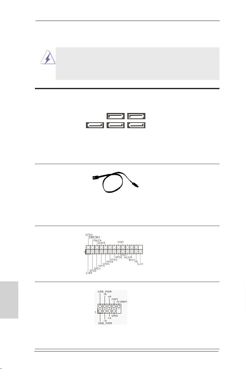
1.4 Колодки и разъемы на плате
Имеющиеся на плате колодки и разъемы НЕ ЯВЛЯЮТСЯ
контактами для перемычек. НЕ УСТАНАВЛИВАЙТЕ перемычки
на эти колодки и разъемы – это приведет к необратимому
повреждению материнской платы!
Разъемы Serial ATA3 пять соединителя Serial ATA3
(SATA3_1, см. стр. 2, п. 16)
(SATA3_2, см. стр. 2, п. 17)
(SATA3_3, см. стр. 2, п. 18)
(SATA3_4, см. стр. 2, п. 15)
(SATA3_5, см. стр. 2, п. 14)
время интерфейс SATA допускает
скорость передачи данных до \ 6,0
Гбит/с.
Информационный Информационный кабель
кабель Serial ATA (SATA) интерфейса SATA3 не является
(дополнительно)
соединителей может быть
подключен либо к жесткому диску
интерфейса SATA3 либо к
материнской плате.
предназначаются для
подключения внутренних
SATA3_5 SATA3_4
устройств хранения с
использованием интерфейсных
кабелей SATA3. В настоящее
SATA3_3 SATA3_2 SATA3_1
направленным. Любой из его
Русский
Разъем порта печати Это интерфейс кабеля порта
(25-выводов LPT1)
(см. cтр. 2, п.27)
печати, обеспечивающий удобное
подключение принтеров.
Колодка USB 2.0 Помимо четыре стандартных
(9-контактный USB5_6)
(см. стр. 2, п. 22)
портов USB 2.0 на панели ввода-
вывода,на данной материнской
плате предусмотрено три разъема
USB 2.0. Каждый разъем USB 2.0
поддерживает два порта USB 2.0.
88
ASRock FM2A75 Pro4-M Motherboard
Page 89

(9-контактный USB7_8)
(см. стр. 2, п. 24)
(9-контактный USB9_10)
(см. стр. 2, п. 26)
Колодка USB 3.0 Помимо два стандартных портов
(19-контактный USB3_3_4)
(см. стр. 2, п. 10)
USB 3.0 на панели ввода- вывода,
на данной материнской плате
предусмотрен один разъем USB
3.0. Этот разъем USB 3.0
поддерживает два порта USB 3.0.
Колодка инфракрасного модуля Данная колодка позволяет
(5-контактный IR1)
(см. стр. 2, п. 29)
подключить дополнительный
модуль беспроводного
инфракрасного
приемопередатчика.
Датчик пользовательского инфракрасного модуля Датчик можно использовать для
(4-контактный CIR1)
(см. стр. 2, п. 25)
подключения дистанционный
приемник.
Аудиоразъем передней Этот интерфейс предназначен
панели для присоединения аудиокабеля
(9-контактный HD_AUDIO1)
(см. cтр. 2, п. 30)
обеспечивающего удобное
передней панели,
подключение аудиоустройств и
управление ими.
ASRock FM2A75 Pro4-M Motherboard
Русский
89
Page 90

1. Система High Denition Audio поддерживает функцию
автоматического обнаружения разъемов (Jack Sensing), однако
для ее правильной pаботы кабель панели в корпусе должен
поддерживать HDA. При сборке системы следуйте инструкциям,
приведенным в нашем руководстве и руководстве пользователя
для корпуса.
2. Если вы используете аудиопанель AC’97, подключите ее к колодке
аудиоинтерфейса передней панели следующим образом:
A. Подключите выводы Mic_IN (MIC) к контактам MIC2_L.
B. Подключите выводы Audio_R (RIN) к контактам OUT2_R, а
выводы Audio_L (LIN) к контактам OUT2_L.
C. Подключите выводы Ground (GND) к контактам Ground (GND).
D. Контакты MIC_RET и OUT_RET предназначены только для
аудиопанели HD. При использовании аудиопанели AC’97
подключать их не нужно.
E. Процедура активации микрофона приведена ниже.
Для ОС Windows® XP:
Выберите «Mixer» (Микшер). Выберите «Recorder» (Устройство
записи). Затем щелкните «FrontMic» (Передний микрофон).
Для ОС Windows® 7 / 7 64-бита, VistaTM / VistaTM 64-бита:
Перейдите к вкладке «FrontMic» (Передний микрофон) в панели
управления Realtek. Отрегулируйте уровень «Recording
Volume» (Громкость записи).
Колодка системной панели Данная колодка обеспечивает
(9-контактный PANEL1)
(см. стр. 2, п. 21)
работу нескольких функций
передней панели системы.
Русский
Подключите к этому разъему кнопку питания, кнопку сброса и
индикатор состояния системы на корпусе в соответствии с
указанным ниже назначением контактов. При подключении кабелей
необходимо соблюдать полярность положительных и отрицательных
контактов.
PWRBTN (кнопка питания):
Подключите к этим контактам кнопку питания на передней панели
корпуса. Способ выключения системы с помощью кнопки питания
можно настроить.
90
ASRock FM2A75 Pro4-M Motherboard
Page 91

RESET (кнопка сброса):
Подключите к этим контактам кнопку сброса на передней панели
корпуса. Нажмите кнопку сброса для перезагрузки компьютера, если
компьютер «завис» и нормальную перезагрузку выполнить не
удается.
PLED (индикатор питания системы):
Подключите к этим контактам индикатор состояния питания на
передней панели корпуса. Этот индикатор светится, когда система
работает. Индикатор мигает, когда система находится в режиме
ожидания S1/S3. Этот индикатор не светится, когда система
находится в режиме ожидания S4, либо выключена (S5).
HDLED (индикатор активности жесткого диска):
Подключите к этим контактам индикатор активности жесткого диска
на передней панели корпуса. Этот индикатор светится, когда
осуществляется считывание или запись данных на жестком диске.
Конструкция передней панели может различаться в зависимости от
корпуса. Модуль передней панели в основном состоит из кнопки
питания, кнопки сброса, индикатора питания, индикатора активности
жесткого диска, динамика и т.п. При подключении к этому разъему
модуля передней панели корпуса удостоверьтесь, что провода
подключаются к соответствующим контактам.
Колодка динамика корпуса Подключите к этой колодке
(4-контактный SPEAKER1)
(см. стр. 2, п. 19)
кабель от динамика на корпусе
компьютера.
разъем Power LED Подключите индикатор Power LED
(3-контактный PLED1)
(см. стр. 2, п. 20)
светодиод продолжит мигать в
режиме S1/S3. Светодиод будет
выключен в режимах S4 или S5
(система выключена).
к этому разъему для отображения
статуса питания системы. Этот
ASRock FM2A75 Pro4-M Motherboard
Русский
91
Page 92

Chassis и Power Fan-соединители Подключите кабели вентилятора к
(4-контактный CHA_FAN1)
(см. стр. 2, п. 12)
(3-контактный PWR_FAN1)
(см. стр. 2, п. 1)
соединителям и присоедините
черный шнур к штырю заземления.
Разъем вентилятора Подключите к этому разъему
процессора кабель вентилятора процессора
(4-контактный CPU_FAN1)
(см. стр. 2, п. 5)
соответствовал контакту земли.
так, чтобы черный провод
Данная материнская плата поддерживает вентиляторы процессора с
4-контактным разъемом (функция тихого режима вентилятора), однако
вентиляторы с 3-контактным разъемом также будут успешно работать, хотя
функция управления скоростью вращения вентилятора окажется
недоступной. Если вы хотите подключить вентилятор процессора с
3-контактным разъемом к разъему вентилятора процессора на данной
материнской плате, для этого следует использовать контакты 1-3.
Контакты 1-3 подключены
Установка вентилятора с 3-контактным разъемом
Русский
(3-контактный CPU_FAN2)
(см. стр. 2, п. 6)
Колодка питания ATX Подключите к этой колодке
(24-контактный ATXPWR1)
(см. стр. 2, п. 9)
кабель питания ATX.
12 124
13
92
ASRock FM2A75 Pro4-M Motherboard
Page 93

Несмотря на то, что эта материнская плата предусматр ивает 24-штыревой разъем питания ATX, работа будет
12
продолжаться, даже если адаптируется традиционный
20-штыревой разъем питания ATX. Для использования
20-штыревого разъема питания ATX вставьте источник
питания вместе со штекером 1 и штекером 13.
Установка 20-штыревого разъема питания ATX
1
Колодка питания 12V-ATX Подключите к этой колодке
(8-контактный ATX12V1)
(см. стр. 2, п. 2)
кабель питания ATX 12V.
Хотя эта объединительная плата обеспечивает ATX с 8 булавками 12V
соединитель власти, это может все еще работать, если Вы принимаете
традиционный ATX с 4-Pin 12V электропитание. Чтобы использовать
электропитание ATX с 4-Pin, пожалуйста включите ваше электропитание
наряду с Булавкой 1 и Прикрепите 5.
4 8
24
13
ATX С 4-Pin 12V Установка Электропитания
1 5
Колодка COM-порта Данная колодка COM-порта
(9-контактный COM1)
(см. стр. 2, п. 28)
позволяет подключить модуль
порта COM.
Датчик открытой крышки Эта материнская плата
(2-контактный CI1)
(см. стр. 2, п. 33)
поддерживает функцию
определения открытой крышки,
которая позволяет определить,
была ли снята крышка корпуса.
Функция требует поддержку со
стороны корпуса.
ASRock FM2A75 Pro4-M Motherboard
Русский
93
Page 94

2. Информация о BIOS
Утилита настройки BIOS (BIOS Setup) хранится во флэш-памяти на материнской плате.
Чтобы войти в программу настройки BIOS Setup, при запуске компьютера нажмите <F2>
или <Del> во время самопроверки при включении питания (Power-On-Self-Test – POST).
Если этого не сделать, то процедуры тестирования POST будут продолжаться обычным
образом. Если вы захотите вызвать BIOS Setup уже после POST, перезапустите систему
с помощью клавиш <Ctrl> + <Alt> + <Delete> или нажатия кнопки сброса на корпусе
системы. Подробную информацию о программе BIOS Setup вы найдете в Руководстве
пользователя (в формате PDF) на компакт-диске поддержки.
3. Информация о компакт-диске
поддержки с программным
обеспечением
Данная материнская плата поддерживает различные операционные системы Microsoft®
Windows®: 7 / 7 64-bit / VistaTM / VistaTM 64-bit / XP. Поставляемый вместе с ней компакт-диск
поддержки содержит необходимые драйверы и полезные утилиты, которые расширяют
возможности материнской платы.
Чтобы начать работу с компакт-диском поддержки, вставьте его в дисковод CD-ROM.
Если в вашем компьютере включена функция автозапуска (AUTORUN), то на экране
автоматически появится главное меню компакт-диска (Main Menu). Если этого не
произошло, найдите в на компакт-диске поддержки файл ASRSETUP.EXE и дважды
щелкните на нем, чтобы открыть меню.
Русский
94
ASRock FM2A75 Pro4-M Motherboard
Page 95

1. Giriş
ASRock’ın kesintisiz titiz kalite denetimi altında üretilen güvenilir bir anakart olan
ASRock FM2A75 Pro4-M anakartını satın aldığınız için teşekkür ederiz. ASRock’ın
kalite ve dayanıklılık konusundaki kararlılığına uygun güçlü tasarımıyla mükemmel
bir performans sunar.
Bu Hızlı Takma Kılavuzu anakarta giriş ve adım adım takma kılavuzu içerir. Anakart
hakkında daha ayrıntılı bilgiyi Destek CD’sinde sunulan kullanıcı kılavuzunda bula-
bilirsiniz.
Anakart özellikleri ve BIOS yazılımı güncelleştirilebileceğinden bu kılavuzun içeriği
önceden haber verilmeksizin değişebilir. Bu belgede değişiklik yapılması durumunda,
güncelleştirilmiş sürüm ayrıca haber verilmeksizin ASRock web sitesinde sunulur. En
son VGA kartlarını ve CPU destek listelerini de ASRock web sitesinde bulabilirsiniz.
ASRock web sitesi http://www.asrock.com
Bu anakartla ilgili teknik desteğe ihtiyacınız olursa, kullandığınız modele özel bilgiler
için lütfen web sitemizi ziyaret edin.
www.asrock.com/support/index.asp
1.1 Paket İçindekiler
ASRock FM2A75 Pro4-M Anakart
(Mikro ATX Form Faktörü: 9,6-inç x 9,6-inç, 24,4 cm x 24,4 cm)
ASRock FM2A75 Pro4-M Hızlı Takma Kılavuzu
ASRock FM2A75 Pro4-M Destek CD’si
2 x Seri ATA (SATA) Veri Kablosu (İsteğe Bağlı)
1 x G/Ç Panel Kalkanı
ASRock FM2A75 Pro4-M Motherboard
Türkçe
95
Page 96

Türkçe
1.2 Özellikler
Platform - Mikro ATX Form Faktörü: 9,6-inç x 9,6-inç, 24,4 cm x 24,4 cm
- Tüm Katı Kapasitör tasarımı
CPU - Yuva Tipi FM2 100W İşlemcileri destekler
- 4 + 2 Güç Fazı Tasarımı
- AMD’nin Cool ‘n’ QuietTM Teknolojisini Destekler
- UMI-Bağlantısı GEN2
Yonga seti - AMD A75 FCH (Hudson-D3)
Bellek - Çift Kanallı DDR3 Belleği Teknolojisi
- 4 x DDR3 DIMM yuva
- DDR3 2600+(OC)/2400(OC)/2133(OC)/1866/1600/1333/1066/
800 ECC olmayan, ara belleksiz bellek
- Sistem belleğinin maks. kapasitesi: 64 GB
- Intel® Extreme Bellek Prolini (XMP)1.3/1.2 destekler
- AMD Bellek Prolini (AMP) destekler
Genişletme - 2 x PCI Express 2.0 x16 yuva (PCIE1: x16 modu; PCIE3: x4
Yuvası modu)
- 1 x PCI Express 2.0 x1 yuva
- 1 x PCI yuva
- AMD Quad CrossFireXTM, CrossFireXTM ve Dual Graphics’i
destekler
Grakler - AMD Radeon HD 7000 grak
- DirectX 11, Pixel Shader 5.0
- Maks. paylaюэlan bellek 2 GB
- Ьз VGA Зэkэю seзeneрi: D-Sub, DVI-D ve HDMI
- 60Hz’de 1920x1200’e kadar maks. зцzьnьrlьkle HDMI 1.4a
Teknolojisini destekler
- 75Hz’de 2560x1600’e kadar maks. зцzьnьrlьkle Dual-link
DVI’yэ destekler
- 60Hz’de 1920x1600’ya kadar maks. зцzьnьrlьkle D-Sub’э
destekler
- Auto Lip Sync, Deep Color (12bpc), HDMI ile xvYCC ve
HBR’yi (Yьksek Bit Hэzlэ Ses) destekler
- HDMI 1.4a bulunan Blu-Ray stereoskopik 3D’yi
desteklemektedir
- AMD Steady VideoTM’yu destekler: Ev/çevrimiçi videoda
otomatik titreşim azaltma için yeni video işleme sonrası özelliği
- DVI ve HDMI portlarэyla HDCP iюlevini destekler
- DVI ve HDMI portlarэyla Tam HD 1080p Blu-ray (BD) /
HD-DVD oynatэmэnэ destekler
96
ASRock FM2A75 Pro4-M Motherboard
Page 97

Ses - İçerik Korumalı (Realtek ALC892 Ses Codec’i) 7,1 Kanal HD
Ses
- Premium Blu-ray ses desteği
LAN - PCIE x1 Gigabit LAN 10/100/1000 Mb/sn
- Realtek RTL8111E
- LAN’da Uyan özelliğini destekler
- LAN Kablo Algılama’yı destekler
- Enerji Verimli Ethernet 802.3az desteği
- PXE’yi destekler
Arka Panel G/З Paneli
G/З - 1 x PS/2 Fare/Klavye Portu
- 1 x D-Sub Portu
- 1 x DVI-D Portu
- 1 x HDMI Portu
- 1 x Optik SPDIF Çıkışı Portu
- 4 x Kullanıma Hazır USB 2.0 Portu
- 1 x eSATA3 Portu
- 2 x Kullanıma Hazır USB 3.0 Portu
- 1 x RJ-45 LAN Portu, LED’li (AKT/LЭNK LED’i ve HIZ LED)
- HD Ses Jakı: Arka Hoparlör/Orta/Bas/Hat Girişi/Ön Hoparlör/
Mikrofon (bkz. DİKKAT 7)
SATA3 - 5 x SATA3 6,0Gb/sn konektör, donanım RAID (RAID 0, RAID
1 ve RAID 10), NCQ, AHCI ve Sistem Aзэkken Bileюen Takma
işlevlerini
USB 3.0 - 2 x Arka USB 3.0 bağlantı noktası, 5Gb/s’ye kadar USB
1.1/2.0/3.0
- 1 x Ön USB 3.0 bağlantısı (2 USB 3.0 bağlantı noktasını
destekler), 5Gb/s’ye kadar USB 1.1/2.0/3.0
Konektör - 5 x SATA3 6.0 Gb/sn konektör
- 1 x KÖ şi
- 1 x Kullanıcı Kızılötesi Modül Bağlantısı
- 1 x Yazdэrma Portu юi
- 1 x COM portu şi
- 1 x Güç LED’i şi
- 1 x Kasaya Yetkisiz Erişim şi
- 2 x CPU FAN konektörü (1 x 4 pin, 1 x 3 pin)
- 1 x Kasa FAN konektörü (4 pin)
- 1 x Gьз FAN konektörü (3 pin)
- 24 pin ATX güç konektörü
- 8 pin 12V güç konektörü
Türkçe
ASRock FM2A75 Pro4-M Motherboard
97
Page 98

- Ön panel ses konektörü
- 3 x USB 2.0 ş (6 USB 2.0 portu destekler)
- 1 x USB 3.0 ş (2 USB 3.0 portu destekler)
BIOS Özelliği - 64 Mb AMI BIOS
- GUI destekli AMI UEFI Geçerli BIOS
- “Tak Çalıştır”ı destekler
- ACPI 1.1 Uyumlu Uyandırma Olayları
- Jumpersız ayarlamayı destekler
- AMBIOS 2.3.1 Desteği
- DRAM, VDDP, VDDR, SB Voltaj Çoklu ayarı
Destek CD’si - Sürücüler, Yardımcı Programlar, AntiVirüs Yazılımı (Deneme
Sürümü), CyberLink MediaEspresso 6.5 Deneme Sürümü
Donanım - CPU Sıcaklık Duyarlılığı
Monitör - Kasa Sıcaklık Duyarlılığı
- CPU/Kasa/Güç Fan Takometresi
- İşlemci/Kasa Sessiz Fanı
- CPU/Kasa Fan Çoklu-Hız Kontrolü
- KASA AÇIK algılaması
- Voltaj İzleme: +12V, +5V, +3,3V, CPU Vcore
İS - Microsoft® Windows® 7 / 7 64-bit / VistaTM / VistaTM 64-bit / XP
uyumlu
Sertikalar - FCC, CE, WHQL
- ErP/EuP Hazır (ErP/EuP hazır güç kaynağı gerekli)
* Ayrıntılı ürün bilgileri için lütfen web sitemizi ziyaret edin: http://www.asrock.com
Türkçe
98
ASRock FM2A75 Pro4-M Motherboard
Page 99

1.3 Jumper'ların Ayarı
Şekilde jumper'ların nasıl ayarlandıkları
gösterilmektedir. Jumper kapağı pinler üzerine
yerleştirildiğinde jumper "Kapalı" dır. Jumper
kapağı pinler üzerindeyken jumper "Açık" tır.
Şekilde pin1 ve pin2'si "Kapalı" olan jumper
kapağı bu 2 pine yerleştirilmiş 3-pinli jumper
gösterilmektedir.
Jumper Ayar
CMOS’u temizleme
(CLRCMOS1, 3-pinli jumper)
(bkz. s.2 No. 23)
Not:
CLRCMOS1, CMOS’daki verilerinizi temizlemenize olanak sağlar. Sistem
parametrelerini temizlemek ve varsayılan ayara sıfırlamak için lütfen bilgisayarı
kapatın ve güç kablosunun şini güç kaynağından çekin. 15 saniye bekledikten
sonra, pin2 ve pin3‘ü CLRCMOS1’de 5 saniye kısaltmak için bir atlatıcı şapkası
kullanın. Ancak, BIOS’u güncelledikten hemen sonra lütfen CMOS’u temizlemeyin.
BIOS’u güncellemeyi tamamladığınızda CMOS’u temizlemeniz gerekirse,
ilk olarak sistemi başlatmanız ve ardından CMOS temizleme işlemini
gerçekleştirmeden önce kapatmanız gereklidir. Parola, tarih, saat, kullanıcı
varsayılan proli, 1394 GUID ve MAC adresinin yalnızca CMOS pili çıkarıldığında
temizleneceğini lütfen aklınızda bulundurunuz.
Clear CMOSDefault
ASRock FM2A75 Pro4-M Motherboard
Türkçe
99
Page 100

1.4 Yerleşik Fişler ve Konektörler
Yerleşik şler ve konektörler jumper DEĞİLDİR. Bu şlerin ve konektörlerin üzerine
jumper kapakları YERLEŞTİRMEYİN. Fişlerin ve konektörlerin üzerine jumper
kapakları yerleştirmek anakartın kalıcı olarak zarar görmesine neden olabilir!
Türkçe
Seri ATA3 Konektörler Bu beş Seri ATA3 (SATA3)
(SATA3_1: bkz. s.2, No. 16)
(SATA3_2: bkz. s.2, No. 17)
(SATA3_3: bkz. s.2, No. 18)
(SATA3_4: bkz. s.2, No. 15)
(SATA3_5: bkz. s.2, No. 14)
konektör, dahili depolama
cihazları için SATA veri
SATA3 arayüzü 6,0 Gb/sn veri
SATA3_3 SATA3_2 SATA3_1
aktarım hızına izin verir.
SATA3_5 SATA3_4
kablolarını destekler. Geçerli
Seri ATA (SATA) SATA veri kablosunu her iki ucu
Veri Kablosu da SATA3 sabit diskine veya
(İsteğe bağlı)
anakarttaki SATA3 konektörüne
bağlanabilir.
Yazdırma Portu Fişi Bu, yazdırma portu kablosu için
(25-pinli LPT1)
(bkz. s.2 No. 27)
yazıcı cihazlarının uygun
bağlanmasını sağlayan bir
arayüzdür.
USB 2.0 Fişleri G/Ç panelindeki varsayılan dört
(9-pinli USB5_6)
(bkz. s.2 No. 22)
USB 2.0 portundan başka, bu
anakartta üç USB 2.0 şi
bulunur. Her USB 2.0 şi iki
USB 2.0 portunu destekler.
100
(9-pinli USB7_8)
(bkz. s.2 No. 24)
ASRock FM2A75 Pro4-M Motherboard
 Loading...