

Page 1

Version 1.0
Published March 2016
Copyright©2016 ASRock INC. All rights reserved.
Copyright Notice:
No part of this documentation may be reproduced, transcribed, transmitted, or
translated in any language, in any form or by any means, except duplication of
documentation by the purchaser for backup purpose, without written consent of
ASRock Inc.
Products and corporate names appearing in this documentation may or may not
be registered trademarks or copyrights of their respective companies, and are used
only for identication or explanation and to the owners’ benet, without intent to
infringe.
Disclaimer:
Specications and information contained in this documentation are furnished for
informational use only and subject to change without notice, and should not be
constructed as a commitment by ASRock. ASRock assumes no responsibility for
any errors or omissions that may appear in this documentation.
With respect to the contents of this documentation, ASRock does not provide
warranty of any kind, either expressed or implied, including but not limited to
the implied warranties or conditions of merchantability or tness for a particular
purpose.
In no event shall ASRock, its directors, ocers, employees, or agents be liable for
any indirect, special, incidental, or consequential damages (including damages for
loss of prots, loss of business, loss of data, interruption of business and the like),
even if ASRock has been advised of the possibility of such damages arising from any
defect or error in the documentation or product.
is device complies with Part 15 of the FCC Rules. Operation is subject to the following
two conditions:
(1) this device may not cause harmful interference, and
(2) this device must accept any interference received, including interference that
may cause undesired operation.
CALIFORNIA, USA ONLY
e Lithium battery adopted on this motherboard contains Perchlorate, a toxic substance
controlled in Perchlorate Best Management Practices (BMP) regulations passed by the
California Legislature. When you discard the Lithium battery in California, USA, please
follow the related regulations in advance.
“Perchlorate Material-special handling may apply, see www.dtsc.ca.gov/hazardouswaste/
perchlorate”
ASRock Website: http://www.asrock.com
Page 2
AUSTRALIA ONLY
Our goods come with guarantees that cannot be excluded under the Australian Consumer
Law. You are entitled to a replacement or refund for a major failure and compensation for
any other reasonably foreseeable loss or damage caused by our goods. You are also entitled
to have the goods repaired or replaced if the goods fail to be of acceptable quality and the
failure does not amount to a major failure. If you require assistance please call ASRock Tel
: +886-2-28965588 ext.123 (Standard International call charges apply).
e terms HDMI™ and HDMI High-Denition Multimedia Interface, and the HDMI
logo are trademarks or registered trademarks of HDMI Licensing LLC in the United
States and other countries.
Manufactured under license under U.S. Patent Nos: 5,956,674; 5,974,380; 6,487,535;
7,003,467 & other U.S. and worldwide patents issued & pending. DTS, the Symbol, &
DTS and the Symbol together is a registered trademark & DTS Connect, DTS Interactive,
DTS Neo:PC are trademarks of DTS, Inc. Product includes soware.
© DTS, Inc., All Rights Reserved.
Page 3

Fatal1ty Story
Who knew that at age 19, I would be a World Champion PC gamer. When I was 13, I actually
played competitive billiards in professional tournaments and won four or ve games o guys
who played at the highest level. I actually thought of making a career of it, but at that young
age situations change rapidly. Because I’ve been blessed with great hand-eye coordination and
a grasp of mathematics (an important element in video gaming) I gravitated to that activity.
GOING PRO
I started professional gaming in 1999 when I entered the CPL (Cyberathlete Professional
League) tournament in Dallas and won $4,000 for coming in third place. Emerging as one
of the top players in the United States, a company interested in sponsoring me ew me to
Sweden to compete against the top 12 players in the world. I won 18 straight games, lost
none, and took rst place, becoming the number one ranked Quake III player in the world
in the process. Two months later I followed that success by traveling to Dallas and defending
my title as the world’s best Quake III player, winning the $40,000 grand prize. From there
I entered competitions all over the world, including Singapore, Korea, Germany, Australia,
Holland and Brazil in addition to Los Angeles, New York and St. Louis.
WINNING STREAK
I was excited to showcase my true gaming skills when defending my title as CPL
Champion of the year at the CPL Winter 2001 because I would be competing in a totally
dierent rst person shooter (fps) game, Alien vs. Predator II. I won that competition and
walked away with a new car. e next year I won the same title playing Unreal Tournament
2003, becoming the only three-time CPL champion of the year. And I did it playing a
different game each year, something no one else has ever done and a feat of which I am
extremely proud.
At QuakeCon 2002, I faced o against my rival ZeRo4 in one of the most highly
anticipated matches of the year, winning in a 14 to (-1) killer victory. Competing at Quakecon
2004, I became the World’s 1st Doom3 Champion by defeating Daler in a series of very
challenging matches and earning $25,000 for the victory.
Since then Fatal1ty has traveled the globe to compete against the best in the world, winning
prizes and acclaim, including the 2005 CPL World Tour Championship in New York City for
a $150,000 rst place triumph. In August 2007, Johnathan was awarded the rst ever Lifetime
Achievement Award in the four year history of the eSports-Award for “showing exceptional
sportsmanship, taking part in shaping eSports into what it is today and for being the prime
representative of this young sport. He has become the gurehead for eSports worldwide”.
Page 4

LIVIN’ LARGE
Since my rst big tournament wins, I have been a “Professional Cyberathlete”, traveling the
world and livin’ large with lots of International media coverage on outlets such as MTV,
ESPN and a 60 Minutes segment on CBS to name only a few. It's unreal - it's crazy. I’m living
a dream by playing video games for a living. I’ve always been athletic and took sports like
hockey and football very seriously, working out and training hard. is discipline helps me
become a better gamer and my drive to be the best has opened the doors necessary to become
a professional.
A DREAM
Now, another dream is being realized – building the ultimate gaming computer, made
up of the best parts under my own brand. Quality hardware makes a huge difference in
competitions…a couple more frames per second and everything gets really nice. It’s all about
getting the computer processing faster and allowing more uid movement around the maps.
My vision for Fatal1ty hardware is to allow gamers to focus on the game without worrying
about their equipment, something I’ve preached since I began competing. I don’t want to
worry about my equipment. I want to be there – over and done with - so I can focus on
the game. I want it to be the fastest and most stable computer equipment on the face of the
planet, so quality is what Fatal1ty Brand products represent.
Johnathan “Fatal1ty” Wendel
e Fatal1ty name, Fatal1ty logos and the Fatal1ty likeness are registered trademarks of Fatal1ty, Inc., and are used
under license. © 2016 Fatal1ty, Inc. All rights reserved. All other trademarks are the property of their respective
owners.
Page 5
Fatal1ty B150 Gaming K4/Hyper Series
DDR 4_A2 (6 4 bit, 28 8-pin m odule )
DDR 4_A1 (6 4 bit, 28 8-pin m odule )
DDR 4_B2 (6 4 bit, 28 8-pin m odule )
DDR 4_B1 (6 4 bit, 28 8-pin m odule )
ATX12V1
USB 2. 0
T: USB1
B: USB 2
ATXP WR 1
LAN
PCIE2
Top:
RJ-45
USB 3.0
T: USB3
B: USB4
Top:
Central/Bass
Center :
REAR SPK
Top:
LINE IN
Center :
FRONT
Bottom :
Optica l
SPDIF
Bottom :
MIC IN
PCIE4
HDLED RESET
PLED PWRBTN
PANEL1
1
USB3_4
1
1
SPK_PLED1
COM1
1
1
HD_AUDIO1
B150 Gaming K4/Hyper
PCIE1
RoHS
5
6
11
10
14
21
22
DVI1
HDMI1
SATA3_1
1
3
2
20
Purity
Sound 3
TM
BIOS
ROM
PS2
Keybo ard
/Mous e
CMOS
Battery
CLRMOS1
1
PCIE3
4
USB3_7 _8
1
13
CPU_FAN2
CPU_FAN1
CHA_FAN1
CHA_FAN4
USB1_2
1
17
1
TPMS1
PCIE5
CHA_FAN2
CHA_FAN3
PCIE_PWR1
SATA3_5
SATA3_3
SATA3_4
SATA3_2
SATA3_0
7
8
9
12
15
16
18
19
23
Intel
B150
USB 3.0
T: USB1
B: USB2
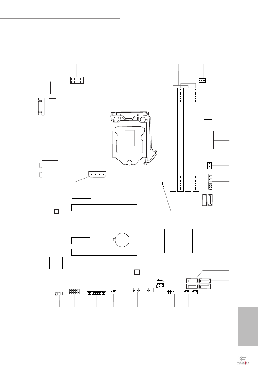
Motherboard Layout
English
1
Page 6
No. Description
1 ATX 12V Power Connector (ATX12V1)
2 2 x 288-pin DDR4 DIMM Slots (DDR4_A1, DDR4_B1)
3 2 x 288-pin DDR4 DIMM Slots (DDR4_A2, DDR4_B2)
4 CPU Fan Connector (CPU_FAN1)
5 ATX Power Connector (ATXPWR1)
6 Chassis Fan Connector (CHA_FAN4)
7 USB 3.0 Header (USB3_7_8)
8 SATA3 Connectors (SATA3_0_1)
9 CPU Fan Connector (CPU_FAN2)
10 SATA3 Connectors (SATA3_3_5)
11 SATA3 Connectors (SATA3_ 2_4)
12 Chassis Fan Connector (CHA_FAN2)
13 Chassis Fan Connector (CHA_FAN1)
14 System Panel Header (PANEL1)
15 Clear CMOS Jumper (CLRMOS1)
16 Power LED and Speaker Header (SPK_PLED1)
17 USB 2.0 Header (USB1_2)
18 USB 2.0 Header (USB3_4)
19 Chassis Fan Connector (CHA_FAN3)
20 TPM Header (TPMS1)
21 COM Port Header (COM1)
22 Front Panel Audio Header (HD_AUDIO1)
23 PCIe Power Connector (PCIE_PWR1)
English
2
Page 7
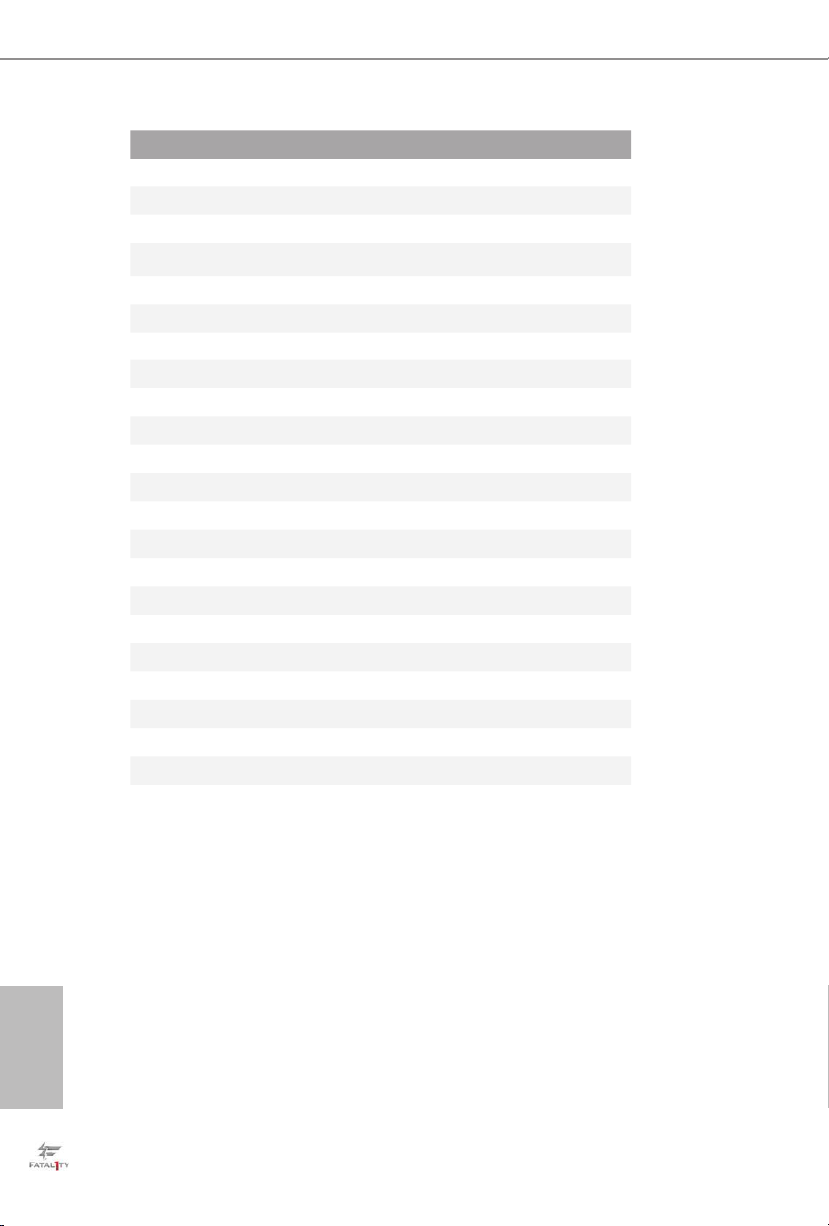
1.4 I/O Panel
6
8
1
Fatal1ty B150 Gaming K4/Hyper Series
2 3
1314
No. Description No. Description
1 Fatal1ty Mouse Port (USB1) 8 Line In (Light Blue)
2 USB 2.0 Port (USB2) 9 Front Speaker (Lime)**
3 DVI-D Port 10 Microphone (Pink)
4 USB 3.0 Ports (USB3_12) 11 Optical SPDIF Out Port
5 LAN RJ-45 Port* 12 USB 3.0 Ports (USB3_34)
6 Central / Bass (Orange) 13 HDMI Port
7 Rear Speaker (Black) 14 PS/2 Mouse/Keyboard Port
CAU TION:
For operating system installation, be sure to plug your USB ash drive into the USB 2.0
Ports (USB12).
4 7
5
12
9
11
10
English
3
Page 8
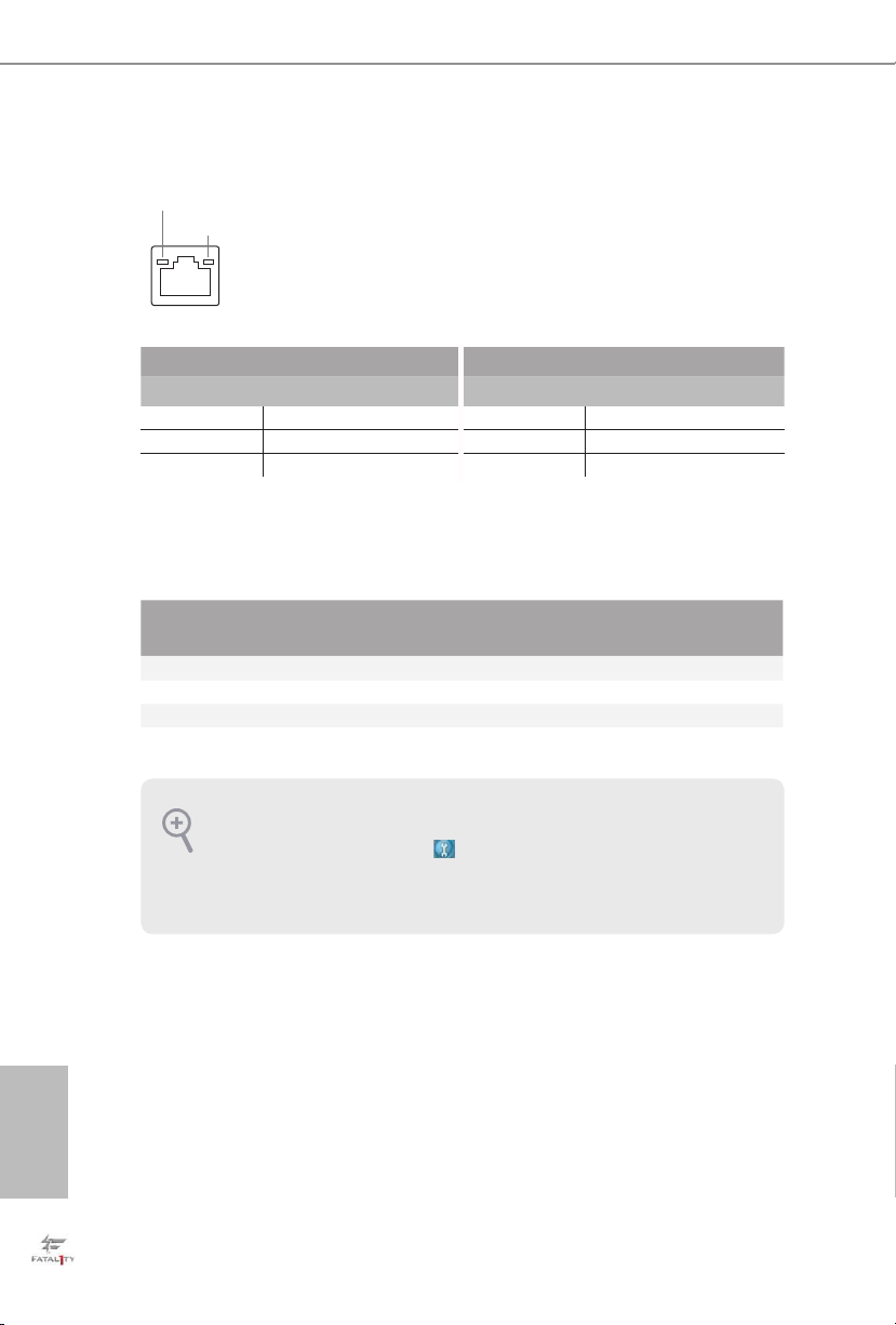
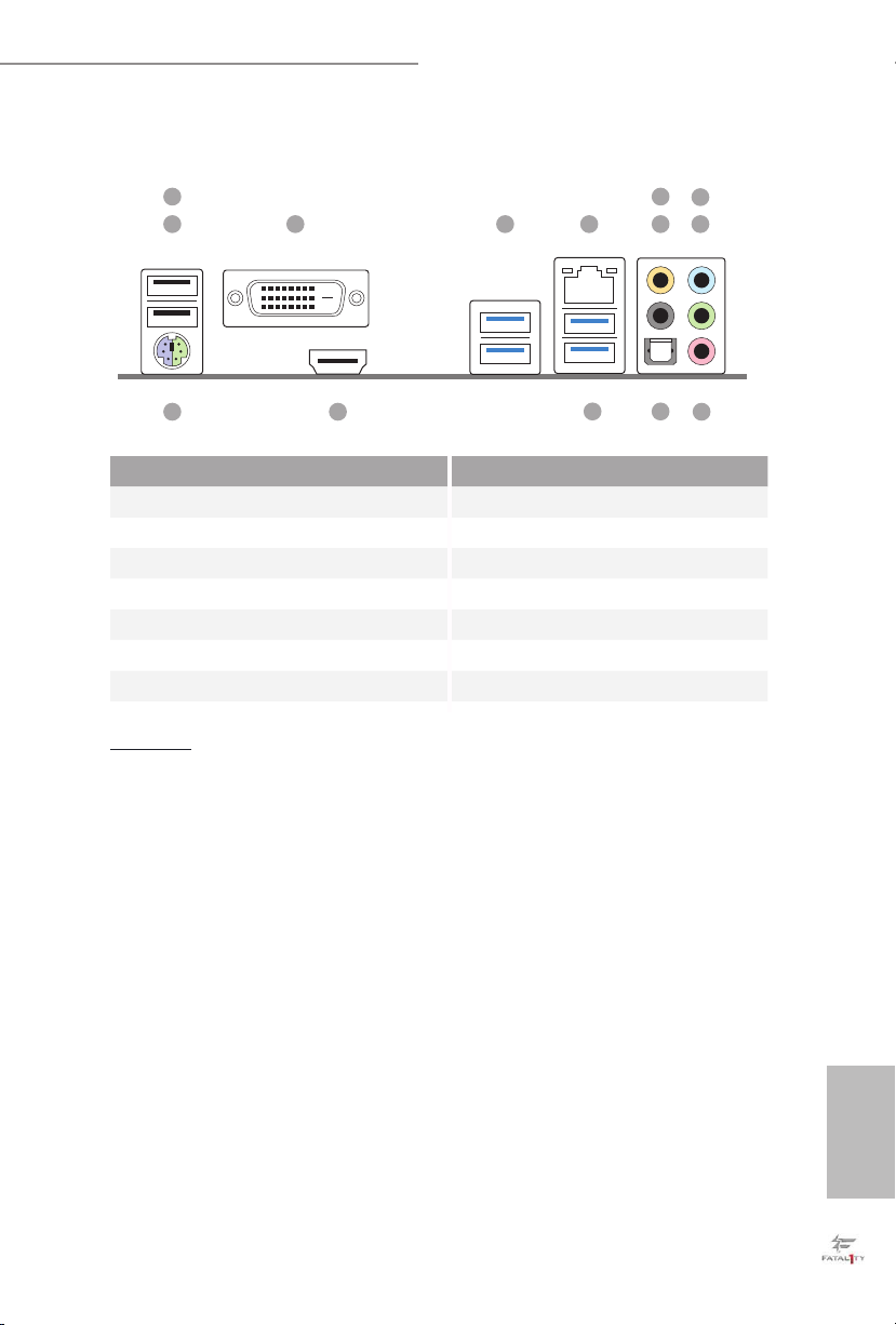
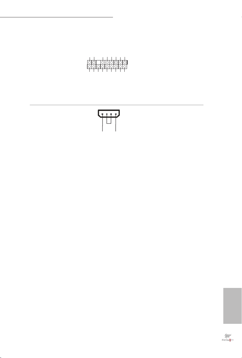
* ere are two LEDs on each LAN port. Please refer to the table below for the LAN port LED indications.
ACT/LINK LED
SPEED LED
LAN Por t
Activity / Link LED Speed LED
Status Description Status Description
O No Link O 10Mbps connection
Blinking Data Activity Orange 100Mbps connection
On Link Green 1Gbps connection
** If you use a 2- channel speaker, plea se connect the speake r’s plug into “Front Speaker Jack”. See the table below
for connection d etails in accordance w ith the type of speaker you use.
English
Audio Output
Channels
Front Speaker
(No. 9)
Rear Speaker
(No. 7)
Central / Bass
(No. 6)
2 V -- -- --
4 V V -- --
6 V V V --
8 V V V V
To enable Multi-Streaming, you need to connect a front panel audio cable to the front
panel audio header. Aer restarting your computer, you will nd the “Mixer” tool on your
system. Please select “Mixe r ToolBox” , click “Enable playback multi-streaming”, and
click “ok”. Choose “2CH”, “4CH”, “6CH”, or “8CH” and then you are allowed to select
“Realtek HDA Primary output” to use the Rear Speaker, Central/Ba ss, and Front Speaker,
or select “Realtek HDA Audio 2nd output” to use the front panel audio.
Line In
(No. 8)
4
Page 9

Fatal1ty B150 Gaming K4/Hyper Series
Chapter 1 Introduction
ank you for purchasing ASRock Fatal1ty B150 Gaming K4/Hyper Series
motherboard, a reliable motherboard produced under ASRock’s consistently
stringent quality control. It delivers excellent performance with robust design
conforming to ASRock’s commitment to quality and endurance.
Becau se the motherboard specications and the BIOS soware might be updated, the
content of this documentation will be subject to change without notice. In case any modications of this documentation occur, the updated version will be available on ASRock’s
website w ithout further notice. If you require technical support related to this motherboard, please visit our website for specic information about the model you are using. You
may nd the l atest VGA cards and CPU support list on ASRock’s website a s well. ASRock
website http://www.asrock.com.
1.1 Package Contents
•ASRock Fatal1ty B150 Gaming K4/Hyper Series Motherboard (ATX Form Factor)
•ASRock Fatal1ty B150 Gaming K4/Hyper Series Quick Installation Guide
•ASRock Fatal1ty B150 Gaming K4/Hyper Series Support CD
•2 x Serial ATA (SATA) Data Cables (Optional)
•1 x I/O Panel Shield
English
5
Page 10

1.2 Specications
Platform
CPU
Chipset
Memory
Expansion
Slot
•ATX Form Factor
•Supports 6
Celeron® Processors (Socket 1151)
•Digi Power design
•10 Power Phase design
•Supports Intel® Turbo Boost 2.0 Technology
•Supports ASRock BCLK Full-range Overclocking
•Supports ASRock Hyper BCLK Engine
•Intel
•Supports Intel® Small Business Basics
•Dual Channel DDR4 Memory Technology
•4 x DDR4 DIMM Slots
•Supports DDR4 2133 non-ECC, un-buered memory
•Supports ECC UDIMM memory modules (operate in non-
ECC mode)
•Max. capacity of system memory: 64GB
•Supports Intel® Extreme Memory Prole (XMP) 2.0
•15μ Gold Contact in DIMM Slots
•2 x PCI Express 3.0 x16 Slots (PCIE2: x16 mode; PCIE4: x4
mode)*
* Supports NVMe SSD as boot disks
•3 x PCI Express 3.0 x1 Slots (Flexible PCIe)
•Supports AMD Quad CrossFireX
•15μ Gold Contact in VGA PCIe Slot (PCIE2)
th
Generation Intel® CoreTM i7/i5/i3/Pentium®/
®
B150
TM
and CrossFireXTM
English
6
Graphics
* Intel® HD Graphics Built-in Visuals and the VGA outputs can
be supported only with processors which are GPU integrated.
•Supports Intel® HD Graphics Built-in Visuals : Intel® Quick
Sync Video with AVC, MVC (S3D) and MPEG-2 Full
HW Encode1, Intel® InTruTM 3D, Intel® Clear Video HD
Technology, Intel® InsiderTM, Intel® HD Graphics 510/530
•Pixel Shader 5.0, DirectX 12
Page 11

Fatal1ty B150 Gaming K4/Hyper Series
•Max. shared memory 1792MB
•Dual graphics output: Support DVI-D and HDMI ports by
independent display controllers
•Supports HDMI with max. resolution up to 4K x 2K
(4096x2304) @ 24Hz / (3840x2160) @ 30Hz
•Supports DVI-D with max. resolution up to 1920x1200 @
60Hz
•Supports Auto Lip Sync, Deep Color (12bpc), xvYCC and
HBR (High Bit Rate Audio) with HDMI Port
(Compliant HDMI monitor is required)
•Supports Accelerated Media Codecs: HEVC, VP8, VP9
•Supports HDCP with DVI-D and HDMI Ports
•Supports Full HD 1080p Blu-ray (BD) playback with DVI-D
and HDMI Ports
Audio
LAN
•7.1 CH HD Audio with Content Protection (Realtek
ALC1150 Audio Codec)
•Premium Blu-ray Audio support
•Supports Surge Protection (ASRock Full Spike Protection)
•Supports Purity Sound
TM
3
- Nichicon Fine Gold Series Audio Caps
- 115dB SNR DAC with Dierential Amplier
- TI® NE5532 Premium Headset Amplier (Supports up to
600 Ohm headsets)
- Pure Power-In
- Direct Drive Technology
- PCB Isolate Shielding
•Supports DTS Connect
•PCIE x1 Gigabit LAN 10/100/1000 Mb/s
TM
•Killer
E2400 Series
•Supports Wake-On-LAN
•Supports Lightning/ESD Protection (ASRock Full Spike
Protection)
•Supports Energy Ecient Ethernet 802.3az
•Supports PXE
English
7
Page 12

Rear Panel
I/O
•1 x PS/2 Mouse/Keyboard Port
•1 x DVI-D Port
•1 x HDMI Port
•1 x Optical SPDIF Out Port
•1 x USB 2.0 Port (Supports ESD Protection (ASRock Full
Spike Protection))
•1 x Fatal1ty Mouse Port (USB 2.0) (Supports ESD Protection
(ASRock Full Spike Protection))
•4 x USB 3.0 Ports (Supports ESD Protection (ASRock Full
Spike Protection))
•1 x RJ-45 LAN Port with LED (ACT/LINK LED and SPEED
LE D)
•HD Audio Jacks: Rear Speaker / Central / Bass / Line in /
Front Speaker / Microphone
English
Storage
Connector
•6 x SATA3 6.0 Gb/s Connectors, support NCQ, AHCI and
Hot Plug
•1 x COM Port Header
•1 x TPM Header
•1 x Power LED and Speaker Header
•2 x CPU Fan Connectors (4-pin) (Smart Fan Speed Control)
•4 x Chassis Fan Connectors (4-pin) (Smart Fan Speed Con-
trol)
* CPU_FAN1 and CHA_FAN1 can auto detect if 3-pin or
4-pin fan is in use.
* e CPU Fan Connector supports the CPU fan of maximum 1A (12W) fan power.
•1 x 24 pin ATX Power Connector
•1 x 8 pin 12V Power Connector
•1 x PCIe Power Connector
•1 x Front Panel Audio Connector
•2 x USB 2.0 Headers (Support 4 USB 2.0 ports) (Supports
ESD Protection (ASRock Full Spike Protection))
•1 x USB 3.0 Header (Supports 2 USB 3.0 ports) (Supports
ESD Protection (ASRock Full Spike Protection))
8
Page 13

Fatal1ty B150 Gaming K4/Hyper Series
BIOS
Feature
Hardware
Monitor
OS
Certications
•AMI UEFI Legal BIOS with multilingual GUI support
•ACPI 5.0 Compliant wake up events
•SMBIOS 2.7 Support
•CPU, GT_CPU, DRAM, VPPM, PCH 1.0V, VCCIO, VC-
CPLL, VCCSA Voltage Multi-adjustment
•CPU/Chassis temperature sensing
•CPU/Chassis Fan Tachometer
•CPU/Chassis Quiet Fan (Auto adjust chassis fan speed by
CPU temperature)
•CPU/Chassis Fan multi-speed control
•Voltage monitoring: +12V, +5V, +3.3V, CPU Vcore, GT_CPU,
DRAM, VPPM, PCH 1.0V, VCCIO, VCCSA
•Microso® Windows® 10 64-bit / 8.1 64-bit / 7 32-bit / 7 64-
bit
* To install Windows® 7 OS, a modied installation disk with
xHCI drivers packed into the ISO le is required. Please refer to
page 147 for more detailed instructions.
* For the updated Windows® 10 driver, please visit ASRock ’s
website for details: http://www.asrock.com.
•FCC, CE, WHQL
•ErP/EuP ready (ErP/EuP ready power supply is required)
* For detailed product information, please visit our website: http://www.asrock.com
Please realize that the re is a certain risk involved with overclocking, including adjusting
the setting in the BIOS, applying Untied Overclocking Technolog y, or using third-party
overclocking tools. O verclocking may aect your system’s stability, or even cause damage to
the components and devices of your system. It should be done at your ow n risk and expense.
We are not responsible for possible damage caused by overclocking.
English
9
Page 14

Chapter 2 Installation
is is an ATX form factor motherboard. Before you install the motherboard, study
the conguration of your chassis to ensure that the motherboard ts into it.
Pre-installation Precautions
Take note of the following precautions before you install motherboard components
or change any motherboard settings.
•Make sure to unplug the power cord before installing or removing the motherboard
components. Failure to do so may cause physical injuries and damages to motherboard
components.
•In order to avoid damage from static electricity to the motherboard’s components,
NEVER place your motherboard directly on a carpet. Also remember to use a grounded
wrist strap or touch a safety grounded object before you handle the components.
•Hold components by the edges and do not touch the ICs.
•Whenever you uninstall any components, place them on a grounded anti-static pad or
in the bag that comes with the components.
•When placing screws to secure the motherboard to the chassis, please do not over-
tighten the screws! Doing so may damage the motherboard.
English
10
Page 15
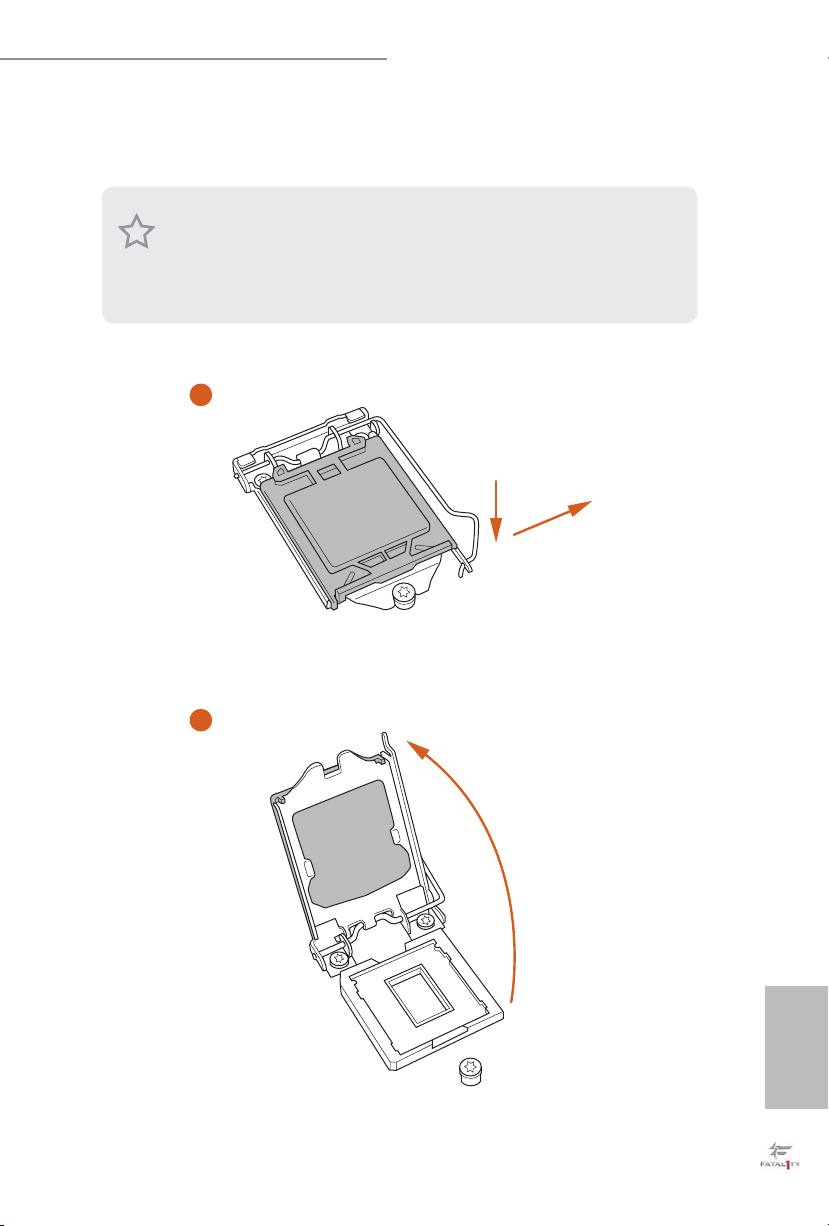
2.1 Installing the CPU
1. Before you insert the 1151-Pin CPU into the socket, please check if the PnP cap is on the
socket, if the CPU surface is unclean, or if there are any bent pins in the sock et. Do not
force to in sert the CPU into the socket if above situation is found. Otherwise, the CPU
will be seriously damaged.
2. Unplug all power cables before in stalling the CPU.
1
Fatal1ty B150 Gaming K4/Hyper Series
A
B
2
English
11
Page 16
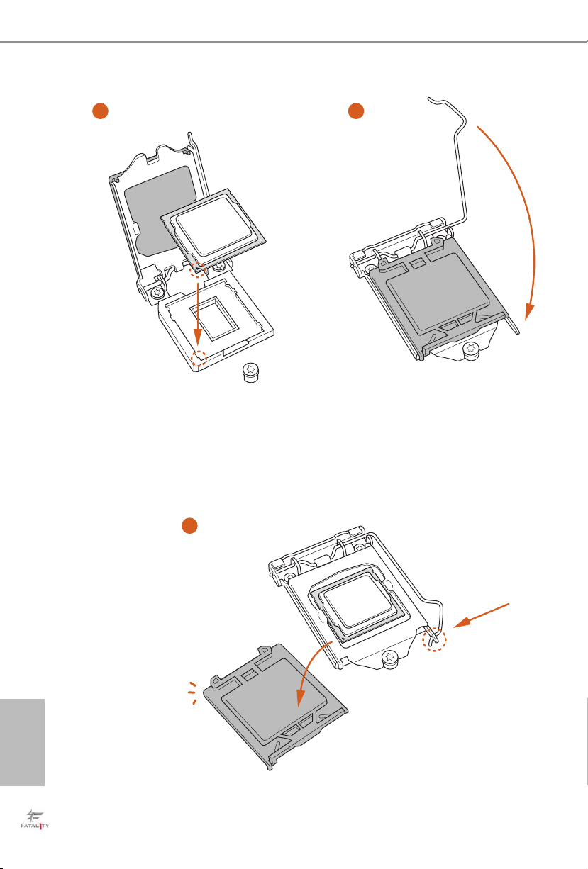
3
4
English
12
5
Page 17

Fatal1ty B150 Gaming K4/Hyper Series
Please save and replace the cover if the processor i s removed. e cover must be placed if
you wish to return the motherboard for aer service.
13
English
Page 18
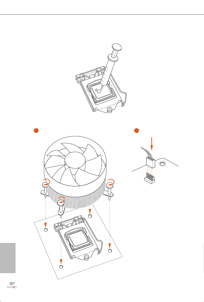
2.2 Installing the CPU Fan and Heatsink
1 2
English
14
FAN
CPU_
Page 19
Fatal1ty B150 Gaming K4/Hyper Series
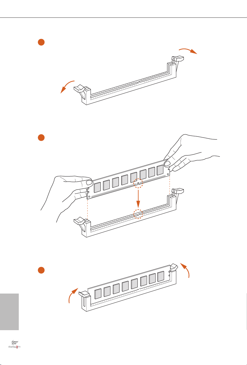
2.3 Installing Memory Modules (DIMM)
is motherboard provides four 288-pin DDR4 (Double Data Rate 4) DIMM slots,
and supports Dual Channel Memory Technology.
1. For dual channel conguration , you always need to in stall identical (the same brand,
speed , size and chip-type) DDR4 DIMM pairs.
2. It is unable to activate Dual Channel Memor y Technology with only one or three memor y
module installed.
3. It is not allowed to install a DDR, DDR2 or DDR3 memory module into a DDR4 sl ot;
otherwise, this motherboard and DIMM may be damaged.
Dual Channel Memory Conguration
Priority DDR4_A1 DDR4_A2 DDR4_B1 DDR4_B2
1 Populated Populated
2 Populated Populated
3 Populated Populated Populated Populated
e DIMM only ts in one correct orientation. It will cause permanent damage to the
motherboard and the DIMM if you force the DIMM into the slot at incorrect orientation.
English
15
Page 20
1
2
English
16
3
Page 21
Fatal1ty B150 Gaming K4/Hyper Series
2.4 Expansion Slots (PCI Express Slots)
ere are 5 PCI Express slots on the motherboard.
Before installing an ex pansion card, please make sure that the power supply is switched o
or the power cord is unplugged. Please read the documentation of the expansion card and
make necessary hardware settings for the card before you start the installation.
PCIe slots:
PCIE1 (PCIe 3.0 x1 slot) is used for PCI Express x1 lane width cards.
PCIE2 (PCIe 3.0 x16 slot) is used for PCI Express x16 lane width graphics cards
PCIE3 (PCIe 3.0 x1 slot) is used for PCI Express x1 lane width cards.
PCIE4 (PCIe 3.0 x16 slot) is used for PCI Express x4 lane width graphics cards.
PCIE5 (PCIe 3.0 x1 slot) is used for PCI Express x1 lane width cards
For a better ther mal environment, please connect a chassi s fan to the motherboard’s chassis fan connector (CHA_ FAN1, CHA_ FAN2, CHA_FAN3 or CHA_ FAN4) when u sing
multiple graphics cards.
17
English
Page 22
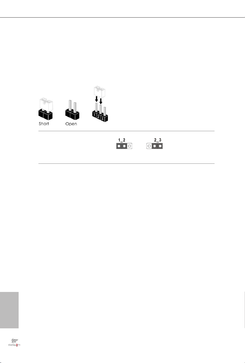
2.5 Jumpers Setup
e illustration shows how jumpers are setup. When the jumper cap is placed on
the pins, the jumper is “Short”. If no jumper cap is placed on the pins, the jumper
is “Open”. e illustration shows a 3-pin jumper whose pin1 and pin2 are “Short”
when a jumper cap is placed on these 2 pins.
Clear CMOS Jumper
(C LR MOS 1)
(see p.1, No. 15)
CLRMOS1 allows you to clear the data in CMOS. To clear and reset the system
parameters to default setup, please turn o the computer and unplug the power
cord from the power supply. Aer waiting for 15 seconds, use a jumper cap to
short pin2 and pin3 on CLRMOS1 for 5 seconds. However, please do not clear the
CMOS right aer you update the BIOS. If you need to clear the CMOS when you
just nish updating the BIOS, you must boot up the system rst, and then shut it
down before you do the clear-CMOS action. Please be noted that the password,
date, time, and user default prole will be cleared only if the CMOS battery is
removed.
Clear CMOSDefault
English
18
Page 23
Fatal1ty B150 Gaming K4/Hyper Series
2.6 Onboard Headers and Connectors
Onboard headers and connectors are NOT jumpers. Do NOT place jumper caps over these
heade rs and connectors. Placing jumper caps over the headers and connectors will cause
permanent damage to the motherboard.
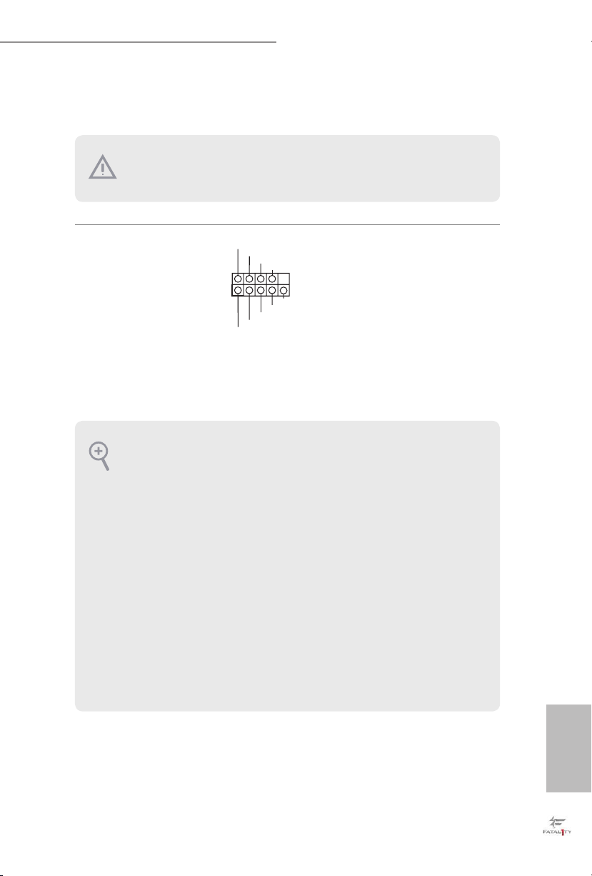
System Panel Header
(9-pi n PANEL1)
(see p.1, No. 14)
PWRBTN (Power Switch):
Connec t to the power switch on the chassi s front panel. You may congure the way to tur n
o your system using the power switch.
RESET (Reset Switch):
Connec t to the reset switch on the chassis front panel. Press the reset sw itch to restart the
computer if the computer f reezes and fails to perform a normal restar t.
PLED (Syste m Power LED):
Connec t to the power status indicator on the chassis front panel. e LED i s on when the
system is operating. e LED keeps blinking when the system is in S1/S3 sleep state. e
LED is o when the system is in S4 sleep state or powered o (S5).
HDLED (Ha rd Drive Activity LED):
Connec t to the hard drive activity LED on the chassis front panel. e LED is on when the
hard drive is reading or wr iting data.
e front panel design may dier by chassis. A front panel module mainly consists of power
switch, reset switch , power LED, hard dr ive activity LED, speaker and etc. When connecting your chassi s front panel module to thi s header, make sure the wire a ssignments and the
pin assignments are matched correctly.
1
PLED+
PLED-
HDLED-
HDLED+
PWRBTN#
GND
RESET#
GND
GND
Connect the power
switch, reset switch and
system status indicator on
the chassis to this header
according to the pin
assignments below. Note
the positive and negative
pins before connecting
the cables.
19
English
Page 24
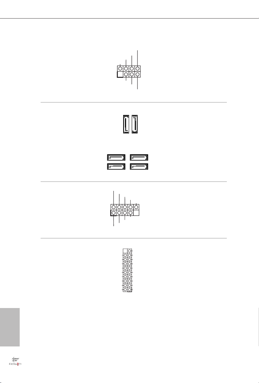
Power LED and Speaker
PLED-
SPEAKER
Header
(7-pin SPK_PLED1)
(see p.1, No. 16)
DUMMY
+5V
1
PLED+
DUMMY
PLED+
Please connect the
chassis power LED and
the chassis speaker to this
header.
Serial ATA3 Connectors
(SATA3_0_1:
see p.1, No. 8)
(SATA3_2_4:
see p.1, No. 11)
(SATA3_3_5:
see p.1, No. 10)
USB 2.0 Headers
(9-pin USB1_2)
(see p.1, No. 17)
(9-pin USB3_4)
(see p.1, No. 18)
USB 3.0 Header
(19-pin USB3_7_8)
(see p.1, No. 7)
SATA3_5
SATA3_3
USB_PWR
1
USB_PWR
Vbus
IntA_PA_SSRX-
IntA_PA_SSRX+
GND
IntA_PA_SSTX-
IntA_PA_SSTX+
GND
IntA_PA_D-
IntA_PA_D+
SATA3_1
-B
-A
+B
GND
GND
+A
SATA3_4
SATA3_2
DUMMY
VbusVbus
IntA_PB_SSRX-
IntA_PB_SSRX+
GND
IntA_PB_SSTX-
IntA_PB_SSTX+
GND
IntA_PB_D-
IntA_PB_D+
Dummy
1
ese six SATA3
connectors support SATA
data cables for internal
SATA3_0
storage devices with up to
6.0 Gb/s data transfer rate.
ere are two headers
on this motherboard.
Each USB 2.0 header can
support two ports.
Besides four USB 3.0
ports on the I/O panel,
there is one header on this
motherboard. Each USB
3.0 header can support
two ports.
English
20
Page 25
Fatal1ty B150 Gaming K4/Hyper Series
1
GND
PRESENCE#
MIC2_R
MIC2_L
MIC_RET
J_SENSE
OUT2_R
OUT_RET
OUT2_L
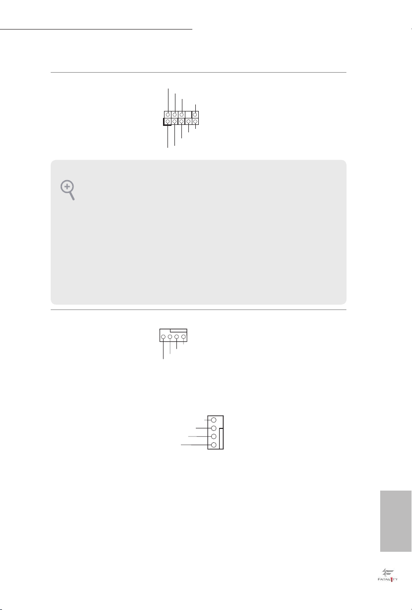
is header is for
connecting audio devices
to the front audio panel.
Front Panel Audio Header
(9-pin HD_ AUDIO1)
(see p.1, No. 22)
1. High Denition Audio support s Jack Sensing, but the panel wire on the chassis must sup port HDA to function correctly. Please follow the instructions in our manual and chassis
manual to install your system.
2. If you use an AC’97 audio panel , please install it to the front panel audio header by the
steps below:
A. Connect Mic_IN (MIC) to MIC2_ L.
B. Conne ct Audio_R (RIN) to OUT2_R and Audio_ L (LIN) to OUT2_ L.
C. Connect Ground (GND) to Ground (GND).
D. MIC_ RET and OUT_RET are for the HD audio panel only. You don’t need to connect
them for the AC’97 audio panel .
E. To activate the front mic, go to the “FrontMic” Tab in the Realtek Control panel and
adjust “Recording Volume”.
Chassis Fan Connectors
(4-pin CHA_FAN1)
(see p.1, No. 13)
(4-pin CHA_FAN2)
4 3 2 1
GND
FAN_VOLTAGE
FAN_SPEED
FAN_SPEED_CONTROL
Please connect fan cables
to the fan connectors and
match the black wire to
the ground pin.
(see p.1, No. 12)
(4-pin CHA_FAN3)
(see p.1, No. 19)
(4-pin CHA_FAN4)
(see p.1, No. 6)
FAN_SPEED_CONTROL
FAN_SPEED
FAN_VOLTAGE
GND
4
3
2
1
English
21
Page 26
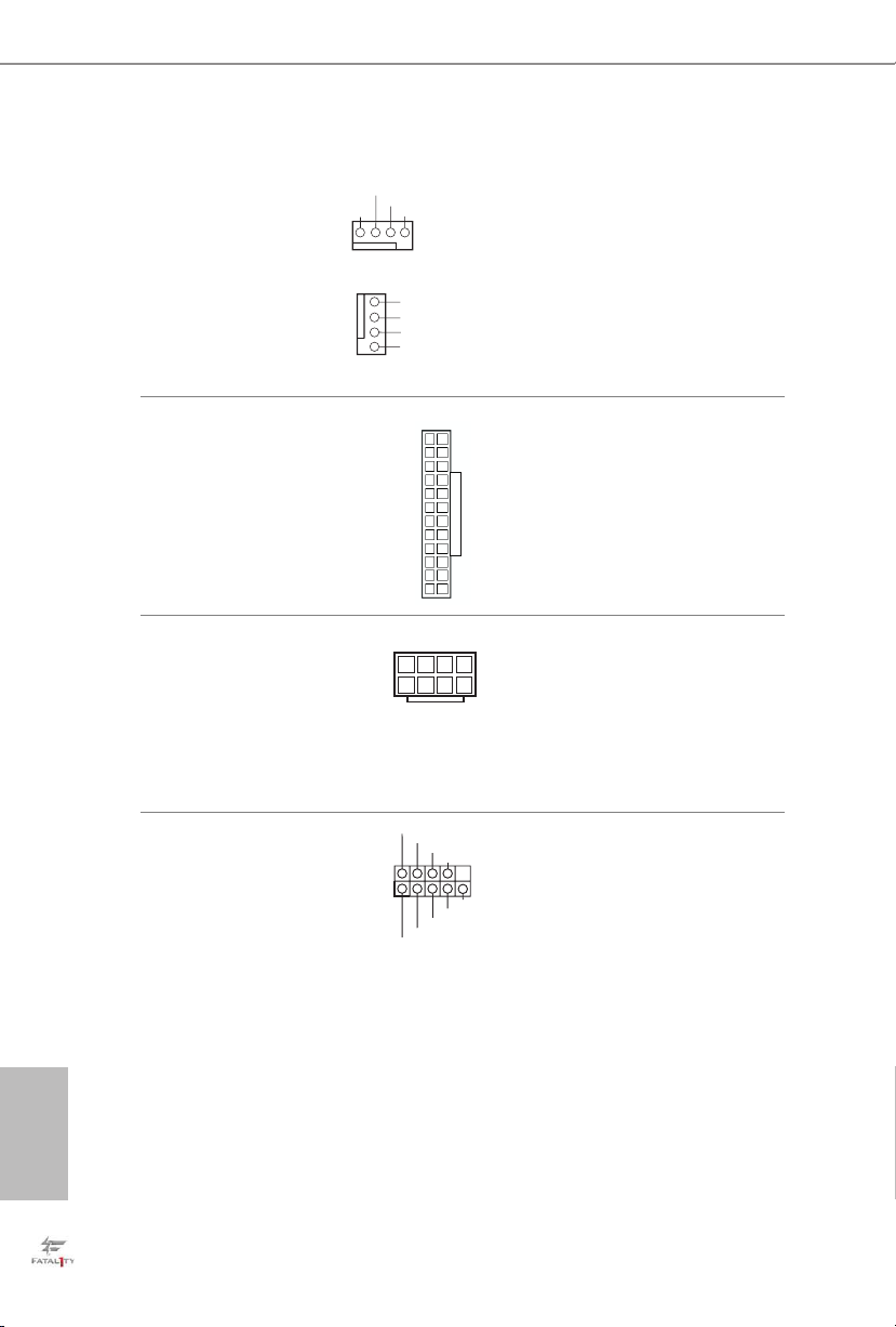
CPU Fan Connectors
14
58
(4-pin CPU_FAN1)
(see p.1, No. 4)
(4-pin CPU_FAN2)
(see p.1, No. 9)
FAN_VOLTAGE
CPU_FAN_SPEED
GND
1 2 3 4
1
2
3
4
FAN_SPEED_CONTROL
GND
FAN_VOLTAGE
CPU_FAN_SPEED
FAN_SPEED_CONTROL
is motherboard provides two 4-Pin CPU fan
(Quiet Fan) connectors.
If you plan to connect a
3-Pin CPU fan, please
connect it to Pin 1-3.
ATX Power Connector
(24-pin ATXPWR1)
(see p.1, No. 5)
ATX 12V Power
Connector
(8-pin ATX12V1)
(see p.1, No. 1)
Serial Port Header
(9-pin COM1)
(see p.1, No. 21)
1
1
12
RRXD1
DDTR#1
TTXD1
DDCD#1
DDSR#1
CCTS#1
RRTS#1
GND
13
24
RRI#1
is motherboard provides a 24-pin ATX power
connector. To use a 20-pin
ATX power supply, please
plug it along Pin 1 and Pin
13.
is motherboard provides an 8-pin ATX 12V
power connector. To use a
4-pin ATX power supply,
please plug it along Pin 1
and Pin 5.
is COM1 header
supports a serial port
module.
English
22
Page 27
Fatal1ty B150 Gaming K4/Hyper Series
TPM Header
(17-pi n TPMS1)
(see p.1, No. 20)
PCIe Power Connector
(4-pin PC IE_PWR1)
(see p.1, No. 23)
GN D
LAD 0
+3V S B
D
GN
GN D
SER IRQ #
S_P WRD WN #
+12V DETECT
+3 V
LAD 1
GND
is connector supports Trusted
Platform Module (TPM) system,
PC ICL K
LAD 3
PC IRS T #
FRA M E
which can securely store keys,
1
digital certicates, passwords,
GN D
LAD 2
SMB _CL K_M AIN
SMB _DA TA_ MAI N
and data. A TPM system also
helps enhance network security,
protects digital identities, and
ensures platform integrity.
Please connect a 4 pin molex
power cable to this connector
when more than three graphics
cards are installed.
23
English
Page 28

1 Einleitung
Vielen Dank, dass Sie sich für die ASRock Fatal1ty B150 Gaming K4/Hyper Series
entschieden haben – ein zuverlässiges Motherboard, das konsequent unter der
strengen Qualitätskontrolle von ASRock hergestellt wurde. Es liefert ausgezeichnete
Leistung mit robustem Design, das ASRocks Streben nach Qualität und Beständigkeit
erfüllt.
Da die technischen Daten des Motherboards sowie die BIOS-Soware aktualisiert werden
können, kann der Inhalt dieser Dokumentation ohne Ankündigung geändert werden. Falls
diese Dokumentation irgendwelchen Änderungen unterliegt, wird die aktualisierte Version
ohne weitere Hinweise auf der ASRock-Webseite zur Verfügung gestellt. Sollten Sie technische
Hilfe in Bezug auf dieses Motherboard benötigen, erhalten Sie auf unserer Webseite spezischen
Informationen über das von Ihnen verwendete Modell. Auch nden Sie eine aktuelle Liste
unterstützter VGA-Karten und Prozessoren auf der ASRock-Webseite: ASRock-Website
http://www.asrock.com.
1.1 Lieferumfang
•ASRock Fatal1ty B150 Gaming K4/Hyper Series-Motherboard (ATX-Formfaktor)
•ASRock Fatal1ty B150 Gaming K4/Hyper Series-Schnellinstallationsanleitung
•ASRock Fatal1ty B150 Gaming K4/Hyper Series-Unterstützungs-CD
•2 x Serial-ATA- (SATA) Datenkabel (optional)
•1 x E/A-Blendenabschirmung
Deutsch
24
Page 29

1.2 Technische Daten
Fatal1ty B150 Gaming K4/Hyper Series
Plattform
Prozessor
Chipsatz
Speicher
Erweiterungssteckplatz
•ATX-Formfaktor
•Unterstützt die Prozessoren Intel® Core
Celeron® der 6. Generation (Sockel 1151)
•Digipower-Design
•10-Leistungsphasendesign
•Unterstützt Intel® Turbo Boost 2.0-Technologie
•Unterstützt ASRock BCLK-Übertaktung (voller Bereich)
•Unterstützt ASRock-Hyper-BCLK-Engine
•Intel® B150
•Unterstützt Intel® Small Business Basics
•Dualkanal-DDR4-Speichertechnologie
•4 x DDR4-DIMM-Steckplätze
•Unterstützt DDR4 2133 non-ECC, ungepuerter Speicher
•Unterstützt ECC-UDIMM-Speichermodule (Betrieb im Non-
ECC-Modus)
•Systemspeicher, max. Kapazität: 64GB
•Unterstützt Intel® Extreme Memory Prole (XMP) 2.0
•15-μ-Goldkontakt in DIMM-Steckplätze
•2 x PCI-Express 3.0-x16-Steckplätze (PCIE2:x16-Modus;
PCIE4:x4-Modus)*
* Unterstützt NVMe-SSD als Bootplatte
•3 x PCI-Express 3.0-x1-Steckplätze (Flexible PCIe)
•Unterstützt AMD Quad CrossFireX
•15-μ-Goldkontakt in VGA-PCIe-Steckplatz (PCIE2)
TM
i7/i5/i3/Pentium®/
TM
und CrossFireXTM
Grakkarte
* Integrierte Intel® HD Graphics-Visualisierung und VGAAusgänge können nur mit Prozessoren unterstützt werden, die
GPU-integriert sind.
•Unterstützt integrierte Intel® HD Graphics-Visualisierung:
Intel® Quick Sync Video mit AVC, MVC (S3D) und MPEG2 Full HW Encode1, Intel® InTruTM 3D, Intel® Clear Video HD
Technology, Intel® InsiderTM, Intel® HD Graphics 510/530
Deutsch
25
Page 30

•Pixel Shader 5.0, DirectX 12
•Max. geteilter Speicher: 1792 MB
•Dualer Grakkartenausgang Unterstützt DVI-D- und HDMI-
Ports durch unabhängige Monitor-Controller
•Unterstützt HDMI mit maximaler Auösung von 4K x 2K
(4096 x 2304) bei 24 Hz / (3840x2160) @ 30Hz
•Unterstützt DVI-D mit maximaler Auösung von 1920 x 1200
bei 60 Hz
•Unterstützt Auto-Lippensynchronizität, hohe Farbtiefe (12
bpc), xvYCC und HBR (Audio mit hoher Bitrate) mit HDMIPort(konformer HDMI-Monitor erforderlich)
•Unterstützt beschleunigte Mediencodecs: HEVC, VP8, VP9
•Unterstützt HDCP mit DVI-D- und HDMI-Ports
•Unterstützt Blu-ray- (BD) Wiedergabe (Full HD/1080p) mit
DVI-D- und HDMI-Ports
Deutsch
Audio
LAN
•7.1-Kanal-HD-Audio mit Inhaltsschutz (Realtek ALC1150-
Audiocodec)
•Erstklassige Blu-ray-Audiounterstützung
•Unterstützt Überspannungsschutz (ASRock Full Spike
Protection)
•Unterstützt Purity Sound
TM
3
- Nichicon-Audiokappen der Fine Gold-Serie
- 115-dB-SRV-DAC mit Dierentialverstärker
- TI® NE5532 – erstklassiger Headset-Verstärker (unterstützt
Headsets mit bis zu 600 Ohm)
- Pure Power-Eingang
- Direct Drive Technology
- PCB-isolierte Abschirmung
•Unterstützt DTS Connect
•PCIE x1 Gigabit LAN 10/100/1000 Mb/s
TM
•Killer
E2400-Serie
•Unterstützt Wake-On-LAN
•Unterstützt Blitzschutz/Schutz gegen elektrostatische Entla-
dung (ASRock Full Spike Protection)
•Unterstützt energieezientes Ethernet 802.3az
•Unterstützt PXE
26
Page 31

Fatal1ty B150 Gaming K4/Hyper Series
Rückblende,
E/A
Speicher
Anschluss
•1 x PS/2-Maus-/Tastaturanschluss
•1 x DVI-D-Port
•1 x HDMI-Port
•1 x Optischer SPDIF-Ausgang
•1 x USB 2.0-Port (unterstützt Schutz gegen elektrostatische
Entladung (ASRock Full Spike Protection))
•1 x Fatal1ty-Mausport (USB 2.0) (unterstützt Schutz
gegen elektrostatische Entladung (ASRock Full Spike
Protection))
•4 x USB 3.0-Ports (unterstützt Schutz gegen
elektrostatische Entladung (ASRock Full Spike
Protection))
•1 x RJ-45-LAN-Port mit LED (Aktivität/Verbindung-LED
und Geschwindigkeit-LED)
•HD-Audioanschlüsse: Hintere Lautsprecher / Zentral /
Bass / Line-in / Vorderer Lautsprecher / Mikrofon
•6 x SATA-III-6,0-Gb/s-Anschlüsse, unterstützt NCQ, AHCI
und Hot-Plugging
•1 x COM-Anschluss-Stileiste
•1 x TPM-Stileiste
•1 x Betrieb-LED- und Lautsprecher-Stileiste
•2 x CPU-Lüeranschlüsse (4-polig) (intelligente
Lüergeschwindigkeitssteuerung)
•4 x Gehäuselüeranschlüsse (4-polig) (intelligente
Lüergeschwindigkeitssteuerung)
•1 x 24-poliger ATX-Netzanschluss
•1 x 8-poliger 12-V-Netzanschluss
•1 x PCIe-Netzanschluss
•1 x Audioanschluss an Frontblende
•2 x USB 2.0-Stileisten (unterstützen 4 USB 2.0-Ports)
(unterstützt Schutz gegen elektrostatische Entladung
(ASRock Full Spike Protection))
•1 x USB 3.0-Stileiste (unterstützt 2 USB 3.0-Ports)
(unterstützt Schutz gegen elektrostatische Entladung
(ASRock Full Spike Protection))
Deutsch
27
Page 32

BIOS-Funktion
•AMI-UEFI-Legal-BIOS mit Unterstützung mehrspra-
chiger grascher Benutzerschnittstellen
•ACPI 5.0-konforme Aufweckereignisse
•SMBIOS 2.7-Unterstützung
•CPU, GT_CPU, DRAM, VPPM, PCH 1.0V, VCCIO,
VCCPLL, VCCSA Mehrfachspannungsanpassung
Deutsch
Hardwareüberwachung
•CPU-/Gehäusetemperaturerkennung
•CPU-/Gehäuselüertachometer
•Lautloser CPU-/Gehäuselüer (automatische Anpassung der
Gehäuselüergeschwindigkeit durch CPU-Temperatur)
•CPU-/Gehäuselüer-Mehrfachgeschwindigkeitssteuerung
•Spannungsüberwachung: +12 V, +5 V, +3,3 V, CPU Vcore,
GT_CPU, DRAM, VPPM, PCH 1,0 V, VCCIO, VCCSA
Betriebssystem
•Microso® Windows® 10 64 Bit / 8.1 64 Bit / 7 32 Bit / 7 64
Bit
* Zur Installation einer Windows® 7-Betriebssystems wird ein
modiziertes Installationslaufwerk mit xHCI-Treibern in der
ISO-Datei benötigt. Detaillierte Anweisungen nden Sie auf
Seite 147.
* Einzelheiten zum aktualisierten Windows® 10-Treiber
entnehmen Sie bitte der ASRock-Webseite: http://www.
asrock.com.
Zertizierungen
* Detaillierte Produktinformationen nden Sie auf unserer Webseite: http://www.asrock.com
Bitte beachten Sie, dass mit einer Übertaktung, zu der die Anpassung von BIOS-Einstellungen,
die Anwendung der Untied Overclocking Technology oder die Nutzung von Übertaktungswerkzeugen von Drittanbietern zählen, bestimmte Risiken verbunden sind. Eine Übertaktung
kann sich auf die Stabilität Ihres Systems auswirken und sogar Komponenten und Geräte Ihres
Systems beschädigen. Sie sollte auf eigene Gefahr und eigene Kosten durchgeführt werden.
Wir übernehmen keine Verantwortung für mögliche Schäden, die durch eine Übertaktung
verursacht wurden.
•FCC, CE, WHQL
•ErP/EuP ready (ErP/EuP ready-Netzteil erforderlich)
28
Page 33

Fatal1ty B150 Gaming K4/Hyper Series
1.3 Jumpereinstellung
Die Abbildung zeigt, wie die Jumper eingestellt werden. Wenn die Jumper-Kappe auf
den Kontakten angebracht ist, ist der Jumper „kurzgeschlossen“. Wenn keine JumperKappe auf den Kontakten angebracht ist, ist der Jumper „oen“. Die Abbildung zeigt
einen 3-poligen Jumper, dessen Kontakt 1 und Kontakt 2 „kurzgeschlossen“ sind,
wenn eine Jumper-Kappe auf diesen 2 Kontakten angebracht ist.
CMOS-löschen-Jumper
(CLRMOS1)
(siehe S. 1, Nr. 15)
CLRMOS1 ermöglicht Ihnen die Löschung der Daten im CMOS. Zum Löschen
und Rücksetzen der Systemparameter auf die Standardeinrichtung schalten Sie
den Computer bitte ab und ziehen das Netzkabel aus der Steckdose. Warten Sie 15
Sekunde, schließen Sie dann Kontakt 2 und Kontakt 3 an CLRMOS1 5 Sekunden
lang mit einer Jumper-Kappe kurz. Löschen Sie den CMOS jedoch nicht direkt nach
der BIOS-Aktualisierung. Falls Sie den CMOS direkt nach Abschluss der BIOSAktualisierung löschen müssen, starten Sie das System zunächst; fahren Sie es dann
vor der CMOS-Löschung herunter. Bitte beachten Sie, dass Kennwort, Datum, Zeit
und Benutzerstandardprol nur gelöscht werden, wenn die CMOS-Batterie entfernt
wird.
CMOS löschenStandard
29
Deutsch
Page 34

1.4 Integrierte Stiftleisten und Anschlüsse
Integrierte Stileisten und Anschlüsse sind KEINE Jumper. Bringen Sie KEINE Jumper-Kappen
an diesen Stileisten und Anschlüssen an. Durch Anbringen von Jumper-Kappen an diesen
Stileisten und Anschlüssen können Sie das Motherboard dauerha beschädigen.
Deutsch
Systemblende-Stileiste
(9-polig, PANEL1)
(siehe S. 1, Nr. 14)
PWRBTN (Ein-/Austaste):
Mit der Ein-/Austaste an der Frontblende des Gehäuses verbinden. Sie können die Abschaltung
Ihres Systems über die Ein-/Austaste kongurieren.
RESET (Reset-Taste):
Mit der Reset-Taste an der Frontblende des Gehäuses verbinden. Starten Sie den Computer
über die Reset-Taste neu, wenn er abstürzt oder sich nicht normal neu starten lässt.
PLED (Systembetriebs-LED):
Mit der Betriebsstatusanzeige an der Frontblende des Gehäuses verbinden. Die LED leuchtet,
wenn das System läu. Die LED blinkt, wenn sich das System im S1/S3-Ruhezustand bendet.
Die LED ist aus, wenn sich das System im S4-Ruhezustand bendet oder ausgeschaltet ist (S5).
HDLED (Festplattenaktivitäts-LED):
Mit der Festplattenaktivitäts-LED an der Frontblende des Gehäuses verbinden. Die LED
leuchtet, wenn die Festplatte Daten liest oder schreibt.
Das Design der Frontblende kann je nach Gehäuse variieren. Ein Frontblendenmodul besteht
hauptsächlich aus Ein-/Austaste, Reset-Taste, Betrieb-LED, Festplattenaktivität-LED, Lautsprecher etc. Stellen Sie beim Anschließen Ihres Frontblendenmoduls an diese Stileiste sicher,
dass Kabel- und Pinbelegung richtig abgestimmt sind.
1
PLED+
PLED-
HDLED-
HDLED+
PWRBTN#
GND
RESET#
GND
GND
Verbinden Sie
Netzschalter, Reset-Taste
und Systemstatusanzeige
am Gehäuse entsprechend
der nachstehenden
Pinbelegung mit dieser
Stileiste. Beachten Sie vor
Anschließen der Kabel die
positiven und negativen
Kontakte.
30
Page 35

Fatal1ty B150 Gaming K4/Hyper Series
PLED-
SPEAKER
Betrieb-LED- und
Lautsprecher-Stileiste
(7-polig, SPK_PLED1)
(siehe S. 1, Nr. 16)
Serial-ATA-III-Anschlüsse
(SATA3_0_1:
siehe S. 1, Nr. 8)
(SATA3_2_4:
siehe S. 1, Nr. 11)
(SATA3_3_5:
siehe S. 1, Nr. 10)
USB 2.0-Stileisten
(9-polig, USB1_2
(siehe S. 1, Nr. 17)
(9-polig, USB3_4)
(siehe S. 1, Nr. 18)
DUMMY
+5V
1
PLED+
SATA3_1
SATA3_5
SATA3_3
USB_PWR
-B
1
-A
USB_PWR
DUMMY
PLED+
SATA3_4
SATA3_2
+B
GND
GND
+A
DUMMY
Bitte verbinden Sie
die Betrieb-LED des
Gehäuses und den
Gehäuselautsprecher mit
dieser Stileiste.
Diese sechs SATA-IIIAnschlüsse unterstützen
SATA-Datenkabel für
SATA3_0
interne Speichergeräte mit
einer Datenübertragungsge
schwindigkeit bis 6,0 Gb/s.
Es gibt zwei Stileisten an
diesem Motherboard. Jede
USB 2.0-Stileiste kann
zwei Ports unterstützen.
USB 3,0-Stileiste
(19-polig, USB3_7_8)
(siehe S. 1, Nr. 7)
Vbus
IntA_PA_SSRX-
IntA_PA_SSRX+
GND
IntA_PA_SSTX-
IntA_PA_SSTX+
GND
IntA_PA_D-
IntA_PA_D+
VbusVbus
IntA_PB_SSRX-
IntA_PB_SSRX+
GND
IntA_PB_SSTX-
IntA_PB_SSTX+
GND
IntA_PB_D-
IntA_PB_D+
Dummy
1
Neben vier USB 3.0-Ports
an der E/A-Blende bendet
sich eine Stileiste an
diesem Motherboard. Jede
USB 3.0-Stileiste kann
zwei Ports unterstützen.
Deutsch
31
Page 36

1
GND
PRESENCE#
MIC2_R
MIC2_L
MIC_RET
J_SENSE
OUT2_R
OUT_RET
OUT2_L
Diese Stileiste dient
dem Anschließen von
Audiogeräten an der
Frontblende.
Audiostileiste
(Frontblende)
(9-polig, HD_AUDIO1)
(siehe S. 1, Nr. 22)
1. High Denition Audio unterstützt Anschlusserkennung, der Draht am Gehäuse muss dazu
jedoch HDA unterstützt. Bitte befolgen Sie zum Installieren Ihres Systems die Anweisungen
in unserer Anleitung und der Anleitung zum Gehäuse.
2. Bei Nutzung eines AC’97-Audiopanels dieses bitte anhand folgender Schritte an der
Audiostileiste der Frontblende installieren:
A. Mic_IN (Mikrofon) mit MIC2_L verbinden.
B. Audio_R (RIN) mit OUT2_R und Audio_L (LIN) mit OUT2_L verbinden.
C. Erde (GND) mit Erde (GND) verbinden.
D. MIC_RET und OUT_RET sind nur für das HD-Audiopanel vorgesehen. Sie müssen sie
nicht für das AC’97-Audiopanel verbinden.
E. Rufen Sie zum Aktivieren des vorderen Mikrofons das „FrontMic (Vorderes
Mikrofon)“-Register in der Realtek-Systemsteuerung auf und passen „Recording Volume
(Aufnahmelautstärke)“ an.
Deutsch
32
Gehäuselüeranschlüsse
(4-polig, CHA_FAN1)
(siehe S. 1, Nr. 13)
(4-polig, CHA_FAN2)
(siehe S. 1, Nr. 12)
(4-polig, CHA_FAN3)
(siehe S. 1, Nr. 19)
(4-polig, CHA_FAN4)
(siehe S. 1, Nr. 6)
GND
FAN_VOLTAGE
FAN_SPEED
FAN_SPEED_CONTROL
FAN_SPEED_CONTROL
FAN_SPEED
FAN_VOLTAGE
GND
Bitte verbinden Sie die
Lüerkabel mit den
Lüeranschlüssen; der
schwarze Draht gehört
zum Erdungskontakt.
4
3
2
1
Page 37

Fatal1ty B150 Gaming K4/Hyper Series
14
58
CPU-Lüeranschlüsse
(4-polig, CPU_FAN1)
(siehe S. 1, Nr. 4)
(4-polig, CPU_FAN2)
(siehe S. 1, Nr. 9)
ATX-Netzanschluss
(24-polig, ATXPWR1)
(siehe S. 1, Nr. 5)
ATX-12-V-Netzanschluss
(8-polig, ATX12V1)
(siehe S. 1, Nr. 1)
FAN_VOLTAGE
CPU_FAN_SPEED
GND
1 2 3 4
1
2
3
4
FAN_SPEED_CONTROL
GND
FAN_VOLTAGE
CPU_FAN_SPEED
FAN_SPEED_CONTROL
1
13
12
24
Dieses Motherboard
bietet zwei 4-polige CPULüeranschlüsse (lautloser
Lüer). Falls Sie einen
3-poligen CPU-Lüer
anschließen möchten,
verbinden Sie ihn bitte mit
Kontakt 1 bis 3.
Dieses Motherboard
bietet einen 24-poligen
ATX-Netzanschluss.
Bitte schließen Sie es zur
Nutzung eines 20-poligen
ATX-Netzteils entlang
Kontakt 1 und Kontakt 13
an.
Dieses Motherboard bietet
einen 8-poligen ATX12-V-Netzanschluss.
Bitte schließen Sie es zur
Nutzung eines 4-poligen
ATX-Netzteils entlang
Kontakt 1 und Kontakt 5
an.
Serieller-Port-Stileiste
(9-polig, COM1)
(siehe S. 1, Nr. 21)
1
RRXD1
DDTR#1
TTXD1
DDCD#1
DDSR#1
CCTS#1
RRTS#1
GND
RRI#1
Diese COM1-Stileiste
unterstützt ein Modul für
serielle Ports.
Deutsch
33
Page 38

TPM-Stileiste
(17-polig, TPMS1)
(siehe S. 1, Nr. 20)
Dieser Anschluss unterstützt das
GN D
LAD 0
LAD 3
+3 V
PC IRS T #
+3V S B
D
GN
GN D
SER IRQ #
S_P WRD WN #
FRA M E
LAD 1
LAD 2
SMB _CL K_M AIN
SMB _DA TA_ MAI N
Trusted Platform Module- (TPM)
PC ICL K
System, das Schlüssel, digitale
1
Zertikate, Kennwörter und Daten
GN D
sicher auewahren kann. Ein
TPM-System hil zudem bei der
Stärkung der Netzwerksicherheit,
schützt digitale Identitäten
und gewährleistet die
Plattformintegrität.
Deutsch
PCIe-Netzanschluss
(4-polig, PCIE_PWR1)
(siehe S. 1, Nr. 23)
GND
+12V DETECT
Bitte verbinden Sie ein 4-poliges
Molex-Netzkabel mit diesem
Anschluss, wenn mehr als drei
Grakkarten installiert sind.
34
Page 39

Fatal1ty B150 Gaming K4/Hyper Series
1 Introduction
Nous vous remercions d’avoir acheté cette carte mère ASRock Fatal1ty B150 Gaming
K4/Hyper Series, une carte mère able fabriquée conformément au contrôle de qualité
rigoureux et constant appliqué par ASRock. Fidèle à son engagement de qualité
et de durabilité, ASRock vous garantit une carte mère de conception robuste aux
performances élevées.
Les spécications de la carte mère et du logiciel BIOS pouvant être mises à jour, le contenu
de ce document est soumis à modication sans préavis. En cas de modications du présent
document, la version mise à jour sera disponible sur le site Internet ASRock sans notication
préalable. Si vous avez besoin d’une assistance technique pour votre carte mère, veuillez visiter
notre site Internet pour plus de détails sur le modèle que vous utilisez. La liste la plus récente
des cartes VGA et des processeurs pris en charge est également disponible sur le site Internet de
ASRock. Site Internet ASRock http://www.asrock.com.
1.1 Contenu de l’emballage
•Carte mère ASRock Fatal1ty B150 Gaming K4/Hyper Series (facteur de forme ATX)
•Guide d’installation rapide ASRock Fatal1ty B150 Gaming K4/Hyper Series
•CD d’assistance ASRock Fatal1ty B150 Gaming K4/Hyper Series
•2 x câbles de données Serial ATA (SATA) (Optionnel)
•1 x panneau de protection E/S
35
Français
Page 40

1.2 Spécications
Plateforme
Processeur
Chipset
Mémoire
•Facteur de forme ATX
•Prend en charge les processeurs 6
i7/i5/i3/Pentium®/Celeron® (Socket 1151)
•Conception Digi Power
•Alimentation à 10 phases
•Prend en charge la technologie Intel® Turbo Boost 2.0
•Prend en charge l’overclocking ASRock BCLK Full-range
•Prend en charge le moteur ASRock Hyper BCLK
•Intel® B150
•Prend en charge Intel® Small Business Basics
•Technologie mémoire double canal DDR4
•4 x fentes DIMM DDR4
•Prend en charge les mémoires sans tampon non ECC DDR4
2133
•Prend en charge les modules mémoire UDIMM ECC
(fonctionne en mode non-ECC)
•Capacité max. de la mémoire système : 64GB
•Prend en charge Intel® Extreme Memory Prole (XMP) 2.0
•Contacts dorés 15μ sur fentes DIMM
e
génération Intel® CoreTM
Français
36
Fente
d’expansion
Graphiques
•2 x fentes PCI Express 3.0 x 16 (PCIE2:mode x16 ;
PCIE4:mode x4)*
* Prend en charge les SSD NVMe comme disques de
démarrage
•3 x fentes PCI Express 3.0 x1 (PCIe exible)
•Prend en charge AMD Quad CrossFireX
•Contact doré 15μ dans fente VGA PCIe (PCIE2)
* La technologie Intel® HD Graphics Built-in Visuals et les sorties
VGA sont uniquement prises en charge par les processeurs
intégrant un contrôleur graphique.
•Prend en charge la technologie Intel® HD Graphics Built-in
Visuals : Intel® Quick Sync Video avec AVC, MVC (S3D) et
MPEG-2 Full HW Encode1, Intel® InTruTM 3D, Intel® Clear
Video HD Technology, Intel® InsiderTM, Intel® HD Graphics
510/530
TM
et CrossFireXTM
Page 41

Fatal1ty B150 Gaming K4/Hyper Series
•Pixel Shader 5.0, DirectX 12
•Mémoire partagée max. 1792Mo
•Double sortie graphique: Prend en charge les ports HDMI et
DVI-D via contrôleurs d’achage indépendants
•Prend en charge la technologie HDMI avec résolution
maximale de 4K × 2K (4096x2304) @ 24Hz / (3840x2160) @
30Hz
•Prend en charge le mode DVI-D avec une résolution
maximale de 1920x1200 @ 60Hz
•Prend en charge les technologies Auto Lip Sync, Deep Color
(12bpc), xvYCC et HBR (High Bit Rate Audio) avec port
HDMI(un moniteur compatible HDMI est requis)
•Prend en charge les codecs multimédias accélérés: HEVC,
VP8, VP9
•Prend en charge HDCP via ports DVI-D et HDMI
•Prend en charge la lecture Blu-ray (BD) Full HD 1080p via
ports DVI-D et HDMI
Audio
Réseau
•Audio 7.1 CH HD avec protection du contenu (codec audio
Realtek ALC1150)
•Compatible audio Blu-ray Premium
•Protection contre les surtensions (Protection complète contre
les pics ASRock)
•Prend en charge Purity Sound
TM
3
- Couvercles audio série en or n Nichicon
- 115dB SNR DAC avec amplicateur diérentiel
- Amplicateur de casque TI® NE5532 Premium (prend en
charge les casques jusqu’à 600 Ohm)
- Alimentation Pure
- Technologie Direct Drive
- Blindage isolant PCB
•Prend en charge DTS Connect
•PCIE x1 Gigabit LAN 10/100/1000 Mo/s
TM
•Killer
série E2400
•Prend en charge la fonction Wake-On-LAN
•Protection contre les orages/décharges électrostatiques
(Protection complète contre les pics ASRock)
•Prend en charge la fonction d’économie d’énergie Ethernet
802.3az
•Prend en charge PXE
Français
37
Page 42

Connectique
du panneau
arrière
•1 x port souris/clavier PS/2
•1 x port DVI-D
•1 x port HDMI
•1 x port sortie optique SPDIF
•1 x port USB 2.0 (Protection contre les décharges
électrostatiques (Protection complète contre les pics
ASRock))
•1 x ports souris Fatal1ty (USB 2.0) (Protection contre les
décharges électrostatiques (Protection complète contre les
pics ASRock))
•4 x ports USB 3.0 (Protection contre les décharges
électrostatiques (Protection complète contre les pics
ASRock))
•1 x port RJ-45 LAN avec LED (LED ACT/LIEN et LED
VITESSE)
•Connecteurs jack audio HD : Haut-parleur arrière / central /
basses / entrée ligne / haut-parleur avant / microphone
Français
38
Stockage
Connecteur
•6 x connecteurs SATA3 6,0 Go/s, compatibles NCQ, AHCI et
«Hot Plug»
•1 x embase pour port COM
•1 x embase TPM
•1 x prise DEL d’alimentation et haut-parleur
•2 x connecteurs pour ventilateur de processeur (4 broches)
(contrôle de vitesse de ventilateur intelligent)
•4 x connecteurs pour ventilateur du châssis (4 broches) (con-
trôle de vitesse de ventilateur intelligent)
•1 x connecteur d’alimentation ATX 24 broches
•1 x connecteur d’alimentation 12V 8 broches
•1 x connecteur d’alimentation PCIe
•1 x connecteur audio panneau frontal
•2 x embases USB 2.0 (4 ports USB 2.0 pris en charge) (Protec-
tion contre les décharges électrostatiques (Protection complète contre les pics ASRock))
•1 x embase USB 3.0 (2 ports USB 3.0 pris en charge)
(Protection contre les décharges électrostatiques (Protection
complète contre les pics ASRock))
Page 43

Fatal1ty B150 Gaming K4/Hyper Series
Caractéristiques du
BIOS
Surveillance
du matériel
Système
d’exploitation
•BIOS UEFI AMI Mo avec prise en charge d’interface
graphique multilingue
•Compatible ACPI 5.0 Wake Up Events
•Prend en charge SMBIOS 2.7
•Réglage de la tension CPU, GT_CPU, DRAM, VPPM, PCH
1.0V, VCCIO, VCCPLL, VCCSA
•Détection de la température du processeur/châssis
•Tachéomètre ventilateur processeur/châssis
•Ventilateur silencieux processeur/châssis (réglage
automatique de la vitesse du ventilateur du châssis d’après la
température du processeur)
•Contrôle simultané des vitesses des ventilateurs processeur/
châssis
•Surveillance de la tension d’alimentation : +12V, +5V,
+3,3V, CPU Vcore, GT_CPU, DRAM, VPPM, PCH 1.0V,
VCCIO, VCCSA
•Microso® Windows® 10 64 bits / 8.1 64 bits / 7 32 bits / 7 64 bits
* Pour installer Windows® 7, un disque d'installation modié avec
les pilotes xHCI intégrés au chier ISO est requis. Reportez-vous à
la page 147 pour des instructions plus détaillées.
* Pour le pilote mis à jour pour Windows® 10, veuillez visiter le
site Web d’ASRock pour plus de détails: http://www.asrock.com.
Certications
•FCC, CE, WHQL
•ErP/EuP Ready (alimentation ErP/EuP ready requise)
* pour des informations détaillées de nos produits, veuillez visiter notre site: http://www.asrock.com
Il est important de signaler que l’overcloking présente certains risques, incluant des
modications du BIOS, l’application d’une technologie d’overclocking déliée et l’utilisation d’outils
d’overclocking développés par des tiers. La stabilité de votre système peut être aectée par ces
pratiques, voire provoquer des dommages aux composants et aux périphériques du système.
L’overclocking se fait à vos risques et périls. Nous ne pourrons en aucun cas être tenus pour
responsables des dommages éventuels provoqués par l’overclocking.
Français
39
Page 44

1.3 Conguration des cavaliers (jumpers)
L’illustration ci-dessous vous renseigne sur la conguration des cavaliers (jumpers).
Lorsque le capuchon du cavalier est installé sur les broches, le cavalier est «courtcircuité». Si le capuchon du cavalier n’est pas installé sur les broches, le cavalier est
«ouvert». L’illustration représente un cavalier à 3 broches dont les broches 1 et 2 sont
«court-circuitées» si un capuchon de cavalier est posé sur ces 2 broches.
Cavalier Clear CMOS
(CLRMOS1)
(voir p.1, No. 15)
CLRMOS1 vous permet d’eacer les donnés de la CMOS. Pour eacer les paramètres
du système et rétablir les valeurs par défaut, veuillez éteindre votre ordinateur
et débrancher son cordon d’alimentation. Patientez 15 secondes, puis utilisez un
capuchon de cavalier pour court-circuiter la broche 2 et la broche 3 sur CLRMOS1
pendant 5 secondes. Toutefois, n’eacez pas la CMOS immédiatement après avoir
mis à jour le BIOS. Si vous avez besoin d’eacer les données CMOS après une mise à
jour du BIOS, vous devez tout d’abord redémarrer le système, puis l’éteindre avant de
procéder à l’eacement de la CMOS. Veuillez noter que les paramètres mot de passe,
date, heure et prol de l’utilisateur seront uniquement eacés en cas de retrait de la
pile de la CMOS.
Fonction Clear CMOSPar défaut
Français
40
Page 45

Fatal1ty B150 Gaming K4/Hyper Series
1.4 Embases et connecteurs de la carte mère
Les embases et connecteurs situés sur la carte NE SONT PAS des cavaliers. Ne placez JAMAIS
de capuchons de cavaliers sur ces embases ou connecteurs. Placer un capuchon de cavalier sur
ces embases ou connecteurs endommagera irrémédiablement votre carte mère.
Embase du panneau
système
(PANNEAU1 à 9 broches)
(voir p.1, No. 14)
PWRBTN (bouton d’alimentation) :
pour brancher le bouton d’alimentation du panneau frontal du châssis. Vous pouvez congurer
la façon dont votre système doit s’arrêter à l’aide du bouton de mise en marche.
RESET (bouton de réinitiélisation) :
pour brancher le bouton de réinitialisation du panneau frontal du châssis. Appuyez
sur le bouton de réinitialisation pour redémarrer l’ordinateur en cas de plantage ou de
dysfonctionnement au démarrage.
PLED (LED d’alimentation du système) :
pour brancher le témoin d’état de l’alimentation du panneau frontal du châssis. Le LED est
allumé lorsque le système fonctionne. Le LED clignote lorsque le système se trouve en mode
veille S1/S3. Le LED est éteint lorsque le système se trouve en mode veille S4 ou hors tension (S5).
HDLED (LED d’activité du disque dur) :
pour brancher le témoin LED d’activité du disque dur du panneau frontal du châssis. Le LED
est allumé lorsque le disque dur lit ou écrit des données.
La conception du panneau frontal peut varier en fonction du châssis. Un module de panneau
frontal est principalement composé d’un bouton de mise en marche, bouton de réinitialisation,
LED d’alimentation, LED d’activité du disque dur, haut-parleur etc. Lorsque vous reliez le
module du panneau frontal de votre châssis sur cette embase, veillez à parfaitement faire
correspondre les ls et les broches.
1
PLED+
PLED-
HDLED-
HDLED+
PWRBTN#
GND
RESET#
GND
GND
Branchez le bouton de
mise en marche, le bouton
de réinitialisation et le
témoin d’état du système
présents sur le châssis
sur cette embase en
respectant la conguration
des broches illustrée
ci-dessous. Repérez
les broches positive et
négative avant de brancher
les câbles.
Français
41
Page 46

Prise DEL d’alimentation
PLED-
SPEAKER
et haut-parleur
(SPK_PLED1 à 7 broches)
(voir p.1, No. 16)
DUMMY
+5V
1
PLED+
DUMMY
PLED+
Veuillez brancher la DEL
d'alimentation du châssis
et le haut-parleur du
châssis sur ce connecteur.
Français
Connecteurs Serial ATA3
(SATA3_0_1:
voir p.1, No. 8)
(SATA3_2_4:
voir p.1, No. 11)
(SATA3_3_5:
voir p.1, No. 10)
Embases USB 2.0
(USB1_2 9broches
(voir p.1, No. 17)
(USB3_4 à 9 broches)
(voir p.1, No. 18)
Embases USB 3.0
(USB3_7_8 19 broches)
(voir p.1, No. 7)
SATA3_5
SATA3_3
USB_PWR
1
USB_PWR
Vbus
IntA_PA_SSRX-
IntA_PA_SSRX+
GND
IntA_PA_SSTX-
IntA_PA_SSTX+
GND
IntA_PA_D-
IntA_PA_D+
SATA3_1
-B
-A
+B
+A
SATA3_4
SATA3_2
GND
DUMMY
GND
VbusVbus
IntA_PB_SSRX-
IntA_PB_SSRX+
GND
IntA_PB_SSTX-
IntA_PB_SSTX+
GND
IntA_PB_D-
IntA_PB_D+
Dummy
1
Ces six connecteurs SATA3
sont compatibles avec les
câbles de données SATA
SATA3_0
pour les appareils de
stockage internes avec un
taux de transfert maximal
de 6,0 Go/s.
Cette carte mère comprend
deux connecteurs. Chaque
embase USB 2,0 peut
prendre en charge deux
ports.
En plus des quatre ports
USB 3.0 sur le panneau
E/S, cette carte mère
est dotée d’une embase
supplémentaire. Chaque
embase USB 3.0 peut
prendre en charge deux
ports..
42
Page 47

Fatal1ty B150 Gaming K4/Hyper Series
Embase audio du panneau
frontal
(HD_AUDIO1 à 9
broches)
(voir p.1, No. 22)
1. L’audio haute dénition prend en charge la technologie Jack Sensing (détection de la che),
mais le panneau grillagé du châssis doit être compatible avec la HDA pour fonctionner
correctement. Veuillez suivre les instructions gurant dans notre manuel et dans le manuel
du châssis pour installer votre système.
2. Si vous utilisez un panneau audio AC’97, veuillez le brancher sur l’embase audio du panneau
frontal en procédant comme suit :
A. branchez Mic_IN (MIC) sur MIC2_L.
B. branchez Audio_R (RIN) sur OUT2_R et Audio_L (LIN) sur OUT2_L.
C. branchez la mise à terre (GND) sur mise à terre (GND).
D. MIC_RET et OUT_RET sont exclusivement réservés au panneau audio HD. Il est inutile
de les brancher avec le panneau audio AC’97.
E. Pour activer le micro frontal, sélectionnez l’onglet «FrontMic» du panneau de contrôle
Realtek et réglez le paramètre «Volume d’enregistrement».
Connecteurs du
ventilateur du châssis
(CHA_FAN1 à 4 broches)
(voir p.1, No. 13)
(CHA_FAN2 à 4 broches)
GND
PRESENCE#
MIC_RET
OUT_RET
1
FAN_SPEED_CONTROL
OUT2_R
MIC2_R
MIC2_L
GND
FAN_VOLTAGE
FAN_SPEED
OUT2_L
J_SENSE
Cette embase sert au
branchement des appareils
audio au panneau audio
frontal.
Veuillez brancher les câbles
du ventilateur sur les
connecteurs du ventilateur,
puis reliez le l noir à la
broche de mise à terre.
(voir p.1, No. 12)
(CHA_FAN3 à 4 broches)
(voir p.1, No. 19)
(CHA_FAN4 4 broches)
(voir p.1, No. 6)
FAN_SPEED_CONTROL
FAN_SPEED
FAN_VOLTAGE
GND
4
3
2
1
Connecteurs du
ventilateur du processeur
(CPU_FAN1 à 4 broches)
(voir p.1, No. 4)
(CPU_FAN2 à 4 broches)
(voir p.1, No. 9)
FAN_VOLTAGE
CPU_FAN_SPEED
GND
1 2 3 4
1
2
3
4
FAN_SPEED_CONTROL
GND
FAN_VOLTAGE
CPU_FAN_SPEED
FAN_SPEED_CONTROL
Cette carte mère est dotée
de deux connecteurs pour
ventilateur de processeur
(Quiet Fan) à 4 broches.
Si vous envisagez de
connecter un ventilateur
de processeur à 3 broches,
veuillez le brancher sur la
Broche 1-3.
Français
43
Page 48

Connecteur d’alimentation
14
58
AT X
(ATXPWR1 à 24 broches)
(voir p.1, No. 5)
1
13
Cette carte mère est
dotée d’un connecteur
d’alimentation ATX à 24
broches. Pour utiliser une
alimentation ATX à 20
broches, veuillez eectuer
12
24
les branchements sur la
Broche 1 et la Broche 13.
Français
Connecteur d’alimentation
ATX 12V
(ATX12V1 à 8 broches)
(voir p.1, No. 1)
Embase pour port série
(COM1 à 9 broches)
(voir p.1, No. 21)
Embase TPM
(TPMS1 à 17 broches)
(voir p.1, No. 20)
Cette carte mère est
dotée d’un connecteur
d’alimentation ATX 12V
à 8 broches. Pour utiliser
une alimentation ATX à 4
broches, veuillez eectuer
les branchements sur la
Broche 1 et la Broche 5.
RRXD1
1
DDTR#1
TTXD1
DDCD#1
DDSR#1
CCTS#1
RRTS#1
GND
RRI#1
Cette embase COM1 prend
en charge un module de
port série.
Ce connecteur prend en charge un
GN D
LAD 0
LAD 3
+3 V
PC IRS T #
+3V S B
D
GN
GN D
SER IRQ #
S_P WRD WN #
FRA M E
LAD 1
LAD 2
SMB _CL K_M AIN
SMB _DA TA_ MAI N
module TPM (Trusted Platform
PC ICL K
Module – Module de plateforme
1
sécurisée), qui permet de sauve-
GN D
garder clés, certicats numériques,
mots de passe et données en toute
sécurité. Le système TPM permet
également de renforcer la sécurité
du réseau, de protéger les identités
numériques et de préserver
l’intégrité de la plateforme.
44
Page 49

Fatal1ty B150 Gaming K4/Hyper Series
Connecteur d’alimentation
PCIe
(PCIE_PWR1 à 4 broches)
(voir p.1, No. 23)
GND
+12V DETECT
Veuillez connecter un câble
d’alimentation molex à 4broches
à ce connecteur lorsque plus
de trois cartes graphiques sont
installées.
45
Français
Page 50

1 Introduzione
Grazie per aver acquistato la scheda madre ASRock Fatal1ty B150 Gaming K4/Hyper
Series, una scheda madre adabile prodotta secondo i severissimi controlli di qualità
ASRock. La scheda madre ore eccellenti prestazioni con un design robusto che si
adatta all'impegno di ASRock di orire sempre qualità e durata.
Dato che le speciche della scheda madre e del soware BIOS possono essere aggiornate, il
contenuto di questa documentazione sarà soggetto a variazioni senza preavviso. Nel caso di
eventuali modiche della presente documentazione, la versione aggiornata sarà disponibile sul
sito Web di ASRock senza ulteriore preavviso. Per il supporto tecnico correlato a questa scheda
madre, visitare il nostro sito Web per informazioni speciche relative al modello attualmente in
uso. È possibile trovare l'elenco di schede VGA più recenti e di supporto di CPU anche sul sito
Web di ASRock. Sito Web di ASRock http://www.asrock.com.
1.1 Contenuto della confezione
•Scheda madre ASRock Fatal1ty B150 Gaming K4/Hyper Series (Form Factor ATX)
•Guida all'installazione rapida di ASRock Fatal1ty B150 Gaming K4/Hyper Series
•CD di supporto ASRock Fatal1ty B150 Gaming K4/Hyper Series
•2 x cavo dati Serial ATA (SATA) (opzionali)
•1 x mascherina metallica posteriore I/O
Italiano
46
Page 51

1.2 Speciche
Fatal1ty B150 Gaming K4/Hyper Series
Piattaforma
CPU
Chipset
Memoria
Alloggio
d’espansione
•Fattore di forma ATX
•Supporta processori 6
Pentium®/Celeron® (Socket 1151)
•Design Digi Power
•Potenza a 10 fasi
•Supporta la tecnologia Intel® Turbo Boost 2.0
•Supporto di CPU unlocked Intel® K-Series
•Supporta gamma completa overclocking BCLK ASRock
•Intel® B150
•Supporta Intel® Small Business Basics
•Tecnologia memoria DDR4 Dual Channel
•4 alloggi DIMM DDR4
•Supporto di memoria DDR4 2133 non-ECC, un-buered
•Supporto di moduli di memoria ECC UDIMM
(funzionamento in modalità non-ECC)
•Capacità max. della memoria di sistema: 64GB
•Supporto di XMP (Extreme Memory Prole) Intel® 2.0
•Contatti d’oro 15μ negli alloggi DIMM
•2 x Alloggi PCI Express 3.0 x16 (PCIE2: Modalità
x16:PCIE4:modalità x4)*
* Supporto di SSD NVMe come disco d’avvio
•3 alloggi PCI Express 3.0 x1 (PCIe essibile)
•Supporta AMD Quad CrossFireX
•Contatti d’oro 15μ nell’alloggio VGA PCIe (PCIE2)
th
Generation Intel® CoreTM i7/i5/i3/
TM
e CrossFireXTM
Italiano
Graca
*Le uscite Intel® HD Graphics Built-in Visualse VGA possono
essere supportate solo con processori dotati di GPU integrata.
•Supporta la videograca integrata della scheda video HD
Intel®: Intel® Quick Sync Video con AVC, MVC (S3D) e
MPEG-2 Full HW Encode1, Intel® InTruTM 3D, tecnologia
Intel® Clear Video HD, Intel® InsiderTM, Intel® HD Graphics
510/530
47
Page 52

•Pixel Shader 5.0, DirectX 12
•Memoria condivisa max. 1792 MB
•Doppia uscita graca: Supporto di porte DVI-D e HDMI
tramite controller display indipendenti
•Supporta HDMI con risoluzione massima no a 4K x 2K
(4096 x 2304) a 24Hz / (3840x2160) @ 30Hz
•Supporta DVI-D con una risoluzione max. no a 1920 x
1200 a 60 Hz
•Supporto delle funzioni Auto Lip Sync, Deep Color (12bpc),
xvYCC e HBR (High Bit Rate Audio) con porta HDMI(È
necessario un monitor compatibile HDMI)
•Supporto accelerazione codec multimediale: HEVC, VP8,
VP9
•Supporto di HDCP con le porte DVI-D e HDMI
•Supporto di riproduzione Full HD 1080p Blu-ray (BD) con
le porte DVI-D e HDMI
Italiano
Audio
LAN
•Audio HD a 7.1 canali con Content Protection (codec audio
Realtek ALC1150)
•Supporto audio Blu-ray Premium
•Supporto protezione da sovratensione (protezione completa
ASRock dai picchi di corrente)
•Supporto di Purity Sound
TM
3
- Cappucci audio Nichicon serie Fine Gold
- 115dB SNR DAC con amplicatore dierenziale
- Amplicatore cue TI® NE5532 Premium (supporta cue
no a 600 Ohm)
- Pura potenza
- Tecnologia Direct Drive
- Schermatura isolata PCB
•Supporta DTS Connect
•PCIE x 1 LAN Gigabit 10/100/1000 Mb/s
•Serie Killer
TM
E2400
•Supporta Wake-On-LAN
•Supporto la protezione da fulmini/scariche elettrostatiche
(ESD) (protezione completa ASRock dai picchi di corrente)
•Supporta Energy Ecient Ethernet 802.3az
•Supporta PXE
48
Page 53

Fatal1ty B150 Gaming K4/Hyper Series
I/O pannello
posteriore
Archiviazione
Connettore
•1 x porta mouse/tastiera PS/2
•1 x porta DVI-D
•1 x porta HDMI
•1 x porta uscita SPDIF ottico
•1 x Porta USB 2.0 (supporto protezione da scariche
elettrostatiche (ESD) (protezione completa ASRock dai picchi
di corrente))
•1 x Porta mouse Fatal1ty (USB 2.0) (supporto protezione da
scariche elettrostatiche (ESD) (protezione completa ASRock
dai picchi di corrente))
•4 x Porte USB 3.0 (supporto protezione da scariche
elettrostatiche (ESD) (protezione completa ASRock dai picchi
di corrente))
•1 x porta LAN RJ-45 con LED (ACT/LINK LED e SPEED
LED)
•Connettori audio HD: altoparlante posteriore/centrale/basso/
ingresso linea/altoparlante anteriore/microfono
•6 x Connettori SATA3 6,0 Gb/s, supportano NCQ, AHCI e
Hot Plug
•1 collettore porta COM
•1 x Collettore TMP
•1 x Connettore LED alimentazione e altoparlante
•2 x Connettori ventola CPU (4 pin) (Smart Fan Speed
Control)
•4 x Connettori ventola telaio (4 pin) (Smart Fan Speed
Control)
•1 connettore alimentazione ATX 24 pin
•1 x Connettore alimentazione 12V 8-pin
•1 x Connettore alimentazione PCIe
•1 connettore audio pannello frontale
•2 x Collettori USB 2.0 (supporto di 4 porte USB 2.0) (supporto
protezione da scariche elettrostatiche (ESD) (protezione
completa ASRock dai picchi di corrente))
•1 x Collettore USB 3.0 (supporta 2 porte USB 3.0) (supporto
protezione da scariche elettrostatiche (ESD) (protezione
completa ASRock dai picchi di corrente))
Italiano
49
Page 54

Funzionalità
BIOS
•AMI UEFI Legal BIOS con interfaccia di supporto multilingue
•Eventi di riattivazione conformi a ACPI 5.0
•Supporto SMBIOS 2.7
•Regolazione multipla tensione CPU, GT_CPU, DRAM,
VPPM, PCH 1.0V, VCCIO, VCCPLL, VCCSA
Italiano
HardwareMonitor
•Rilevamento temperatura CPU/telaio
•Tachimetro ventola CPU/telaio
•Ventola silenziosa CPU/telaio (regolazione automatica velocità
in base alla temperatura della CPU)
•Ventola CPU/chassis con controllo di varie velocità
•Monitoraggio tensione: +12V, +5V, +3,3V, CPU Vcore, GT_
CPU, DRAM, VPPM, PCH 1.0V, VCCIO, VCCSA
SO
•Microso® Windows® 10 64-bit / 8.1 64-bit / 7 32-bit / 7 64-bit
* Per installare Windows® 7, è necessario un disco di installazione
modicato con i driver xHCI integrati nel le ISO. Fare riferimento a pagina 147 per altre istruzioni dettagliate.
* Per il driver aggiornato di Windows® 10, visitare il sito ASRock
all’indirizzo: http://www.asrock.com.
Certicazioni
•FCC, CE, WHQL
•ErP/EuP Ready (è necessaria alimentazione ErP/EuP ready)
* Per informazioni dettagliate sul prodotto, visitare il nostro sito Web: http://www.asrock.com
Prestare attenzione al potenziale rischio previsto nella pratica di overclocking, inclusa la
regolazione delle impostazioni nel BIOS, l'applicazione di tecnologia di Untied Overclocking o
l'utilizzo di strumenti di overclocking di terze parti. L'overclocking può inuenzare la stabilità
del sistema o perno provocare danni ai componenti e ai dispositivi del sistema. Occorre
eseguirlo a proprio rischio e spese. Non ci riterremo responsabili per possibili danni provocati
da overclocking.
50
Page 55

Fatal1ty B150 Gaming K4/Hyper Series
1.3 Impostazione jumper
L'illustrazione mostra in che modo vengono impostati i jumper. Quando il cappuccio
del jumper è posizionato sui pin, il jumper è "cortocircuitato". Se sui pin non è
posizionato alcun cappuccio del jumper, il jumper è "aperto". L'illustrazione mostra
un jumper a 3 pin i cui pin1 e pin2 sono "cortocircuitati" quando un cappuccio del
jumper è posizionato su questi 2 pin.
Jumper per azzerare la
CMOS
(CLRMOS1)
(vedere pag. 1, n. 15)
CLRMOS1 permette si azzerare i dati nella CMOS. Per azzerare e reimpostare
i parametri del sistema alla congurazione predenita, spegnere il computer e
scollegare il cavo di alimentazione dalla rete. Attendere 15 secondi, quindi usare un
cappuccio jumper per cortocircuitare il pin 2 ed il pin 3 su CLRMOS1 per 5 secondi.
Tuttavia, non azzerare la CMOS subito dopo aver aggiornato il BIOS. Se è necessario
azzerare la CMOS dopo l'aggiornamento del BIOS, è necessario riavviare prima il
sistema e in seguito spegnerlo prima di eseguire l'operazione di azzeramento della
CMOS. La password, la data, l'ora e il prolo predenito dell'utente saranno azzerati
solo se viene rimossa la batteria della CMOS.
Azzerare la CMOSpredenito
51
Italiano
Page 56

1.4 Header e connettori sulla scheda
Gli header e i connettori sulla scheda NON sono jumper. NON posizionare cappucci del jumper
su questi header e connettori. Il posizionamento di cappucci del jumper su header e connettori
provocherà danni permanenti alla scheda madre.
Italiano
Header sul pannello del
sistema
(PANEL1 a 9 pin)
(vedere pag. 1, n. 14)
PWRBTN (interruttore di alimentazione):
collegare all'interruttore dell'alimentazione sul pannello anteriore dello chassis. È possibile
congurare il modo in cui spegnere il sistema utilizzando l'interruttore dell'alimentazione.
RESET (interruttore di reset):
collegare all'interruttore di reset sul pannello anteriore dello chassis. Premere l'interruttore
di reset per riavviare il computer se il computer si blocca e non riesce ad eseguire un normale
riavvio.
PLED (LED alimentazione del sistema):
collegare all'indicatore di stato dell'alimentazione sul pannello anteriore dello chassis. Il LED
è acceso quando il sistema è in funzione. Il LED continua a lampeggiare quando il sistema si
trova nello stato di sospensione S1/S3. Il LED è spento quando il sistema si trova nello stato di
sospensione S4 o quando è spento (S5).
HDLED (LED di attività disco rigido):
collegare al LED di attività disco rigido sul pannello anteriore dello chassis. Il LED è acceso
quando il disco rigido sta leggendo o scrivendo dati.
Il design del pannello anteriore può cambiare a seconda dello chassis. Un modulo di pannello
anteriore è composto principalmente da interruttore di alimentazione, interruttore di reset,
LED di alimentazione, LED di attività disco rigido, altoparlante, ecc. Quando si collega il
modulo del pannello anteriore dello chassis a questo header, accertarsi che le assegnazioni del
lo e le assegnazioni del pin corrispondano correttamente.
1
PLED+
PLED-
HDLED-
HDLED+
PWRBTN#
GND
RESET#
GND
GND
Collegare l'interruttore
dell'alimentazione,
l'interruttore di reset e
l'indicatore dello stato del
sistema sullo chassis su
questo header secondo
la seguente assegnazione
dei pin. Annotare i pin
positivi e negativi prima di
collegare i cavi.
52
Page 57

Fatal1ty B150 Gaming K4/Hyper Series
PLED-
SPEAKER
Connettore LED
alimentazione e
altoparlante
(SPK_PLED1 7 pin)
(vedere pag. 1, n. 16)
Connettori Serial ATA3
(SATA3_0_1:
vedere pag. 1, n. 8)
(SATA3_2_4:
vedere pag. nr. 11)
(SATA3_3_5:
vedere pag.1, n. 10)
Header USB 2.0
(USB1_2 9 pin
(vedere pag. 1, n. 17)
(9-pin USB3_4)
(vedere pag. 1, n. 18)
DUMMY
+5V
1
PLED+
SATA3_1
SATA3_5
SATA3_3
USB_PWR
-B
1
-A
USB_PWR
DUMMY
PLED+
SATA3_4
SATA3_2
+B
GND
GND
+A
DUMMY
Collegare i LED
alimentazione e
l’altoparlante a questo
connettore.
Questi sei connettori
SATA3 supportano cavi
dati SATA per dispositivi
SATA3_0
di archiviazione interna,
con una velocità di
trasferimento dati no a 6,0
Gb/s.
Ci sono due connettori
su questa scheda madre.
Ciascun header USB 2.0
può supportare due porte.
Header USB 3.0
(USB3_7_8 19 pin)
(vedere pag. 1, n. 7)
Vbus
IntA_PA_SSRX-
IntA_PA_SSRX+
GND
IntA_PA_SSTX-
IntA_PA_SSTX+
GND
IntA_PA_D-
IntA_PA_D+
VbusVbus
IntA_PB_SSRX-
IntA_PB_SSRX+
GND
IntA_PB_SSTX-
IntA_PB_SSTX+
GND
IntA_PB_D-
IntA_PB_D+
Dummy
1
Oltre alle quattro porte
USB 3.0 del pannello I/
O, questa scheda madre
è dotata di un collettore.
Ciascun header USB 3.0
può supportare due porte.
Italiano
53
Page 58

1
GND
PRESENCE#
MIC2_R
MIC2_L
MIC_RET
J_SENSE
OUT2_R
OUT_RET
OUT2_L
Questo header serve a
collegare i dispositivi
audio al pannello audio
anteriore.
Header audio pannello
anteriore
(AUDIO1_HD a 9 pin)
(vedere pag. 1, n. 22)
1. L'audio ad alta denizione supporta le funzioni Jack sensing, ma il lo del pannello sullo
chassis deve supportare HDA per funzionare correttamente. Seguire le istruzioni presenti nel
nostro manuale e nel manuale dello chassis per installare il sistema.
2. Se si utilizza un pannello audio AC’97, installarlo sull'header audio del pannello anteriore
seguendo le fasi di seguito:
A. Collegare Mic_IN (MIC) a MIC2_L.
B. Collegare Audio_R (RIN) a OUT2_R e Audio_L (LIN) a OUT2_L.
C. Collegare Ground (GND) a Ground (GND).
D. MIC_RET e OUT_RET servono soltanto per il pannello audio HD. Non è necessario
collegarli per il pannello audio AC’97.
Per attivare il microfono anteriore, andare alla scheda “FrontMic” nel pannello di controllo
Realtek e regolare il “Volume di registrazione”.
Italiano
54
Connettori ventola telaio
(CHA_FAN1 a 4 pin)
(vedere pag. 1, n. 13)
(CHA_FAN2 a 4 pin)
(vedere pag. 1, n. 12)
(CHA_FAN3 a 4 pin)
(vedere pag. 1, n. 19)
(CHA_FAN4 a 4 pin)
(vedere pag. 1, n. 6)
Connettori della ventola
della CPU
(CPU_FAN1 a 4 pin)
(vedere pag. 1, n. 4)
(CPU_FAN2 a 4 pin)
(vedere pag. 1, n. 9)
GND
FAN_VOLTAGE
FAN_SPEED
FAN_SPEED_CONTROL
FAN_SPEED_CONTROL
FAN_SPEED
FAN_VOLTAGE
GND
FAN_VOLTAGE
CPU_FAN_SPEED
GND
FAN_SPEED_CONTROL
1 2 3 4
1
GND
2
FAN_VOLTAGE
CPU_FAN_SPEED
3
FAN_SPEED_CONTROL
4
Collegare i cavi della
ventola ai connettori della
ventola e far corrispondere
il lo nero al pin di terra.
4
3
2
1
Questa scheda madre
fornisce due connettori
ventola CPU a 4 pin
(Quiet Fan). Se si decide di
collegare una ventola della
CPU a 3 pin, collegarla al
pin 1-3.
Page 59

Fatal1ty B150 Gaming K4/Hyper Series
14
58
Connettore di
alimentazione ATX
(ATXPWR1 a 24 pin)
(vedere pag. 1, n. 5)
Connettore di
alimentazione ATX da
12 V
(ATX12V1 a 8 pin)
(vedere pag. 1, n. 1)
Header porta seriale
(COM1 a 9 pin)
(vedere pag. 1, n. 21)
Header TPM
(TPMS1 a 17 pin)
(vedere pag. 1, n. 20)
1
13
Questa scheda madre è
dotata di un connettore
di alimentazione ATX
a 24 pin. Per utilizzare
un'alimentazione ATX a
20 pin, collegarla lungo il
12
24
pin1 e il pin 13.
Questa scheda madre è
dotata di un connettore
di alimentazione ATX da
12 V a 8 pin. Per utilizzare
un'alimentazione ATX a
4 pin, collegarla lungo il
pin1 e il pin 5.
1
RRXD1
DDTR#1
TTXD1
DDCD#1
DDSR#1
CCTS#1
RRTS#1
GND
RRI#1
Questo header COM1
supporta un modulo di
porta seriale.
Questo connettore supporta il
GN D
LAD 0
+3 V
+3V S B
D
GN
GN D
LAD 1
SER IRQ #
S_P WRD WN #
PC ICL K
LAD 3
PC IRS T #
FRA M E
LAD 2
sistema Trusted Platform Module
1
(TPM), che può archiviare in
modo sicuro chiavi, certicati
GN D
digitali, password e dati. Un
sistema TPM permette anche di
SMB _CL K_M AIN
SMB _DA TA_ MAI N
potenziare la sicurezza della rete,
di proteggere identità digitali
Italiano
e di garantire l'integrità della
piattaforma.
55
Page 60

Connettore alimentazione
PCIe
(4-pin PCIE_PWR1)
(vedere pag. 1, n. 23)
GND
+12V DETECT
Collegare un cavo di
alimentazione molex a 4 pin
a questo connettore quando
sono installate più di tre schede
grache.
Italiano
56
Page 61

Fatal1ty B150 Gaming K4/HyperC Series
1 Introducción
Gracias por comprar la placa base ASRock Fatal1ty B150 Gaming K4/Hyper Series,
una placa base able fabricada según el rigurosísimo control de calidad de ASRock.
Ofrece un rendimiento excelente con un diseño resistente de acuerdo con el
compromiso de calidad y resistencia de ASRock.
Ya que las especicaciones de la placa base y el soware del BIOS podrán ser actualizados, el
contenido que aparece en esta documentación estará sujeto a modicaciones sin previo aviso.
Si esta documentación sufre alguna modicación, la versión actualizada estará disponible en
el sitio web de ASRock sin previo aviso. Si necesita asistencia técnica relacionada con esta placa
base, visite nuestro sitio web para obtener información especíca sobre el modelo que esté
utilizando. Podrá encontrar las últimas tarjetas VGA, así como la lista de compatibilidad de la
CPU, en el sitio web de ASRock. Sitio web de ASRock http://www.asrock.com.
1.1 Contenido del paquete
•Placa base ASRock Fatal1ty B150 Gaming K4/Hyper Series (Factor de forma ATX)
•Guía de instalación rápida de ASRock Fatal1ty B150 Gaming K4/Hyper Series
•CD de soporte de ASRock Fatal1ty B150 Gaming K4/Hyper Series
•2 x Cables de datos Serial ATA (SATA) (Opcional)
•1 x escudo panel I/O
57
Español
Page 62

1.2 Especicaciones
Español
Plataforma
CPU
Conjunto
de chips
Memoria
Ranura de
expansión
•Factor de forma ATX
•Admite la familia de procesadores Intel® Core
Pentium®/Celeron® (zócalo 1151) de la 6ª generación
•Diseño Digi Power
•Diseño de fase de alimentación 10
•Compatible con la tecnología de Intel® Turbo Boost 2.0
•Compatible con overclocking de rango completo BCLK de
ASRock
•Admite motor hiper-BCLK de ASRock
•Intel® B150
•Compatible con Intel® Small Business Basics
•Tecnología de memoria DDR4 de doble canal
•4 x Ranuras DIMM DDR4
•Admite memoria sin búfer DDR4 2133 no ECC.
•Admite módulos de memoria UDIMM ECC (funcionamiento
en modo no ECC)
•Capacidad máxima de la memoria del sistema: 64GB
•Admite Perl de memoria extremo de Intel® (XMP) 2.0
•Contacto 15μ Gold en ranuras DIMM
•2 x Ranuras PCI Express 3.0 x16 (PCIE2:modo x16;
PCIE4:modo x4)*
* Admite unidad de estado sólido de NVMe como disco de
arranque
•3 ranuras PCI Express 3.0 x1 (PCIe exible)
•Compatible con AMD Quad CrossFireX
•Contacto 15μGold en ranura VGA PCIe (PCIE2)
TM
i7/i5/i3/
TM
y CrossFireXTM
58
Grácos
* La Tecnología visual integrada de grácos HD de Intel® y las
salidas de VGA son compatibles únicamente con procesadores
con GPU integrado.
•Compatible con la Tecnología visual integrada de grácos HD
de Intel®: Intel® Quick Sync Video con AVC, MVC (S3D) y
MPEG-2 Full HW Encode1, Intel® InTruTM 3D, Intel® Clear
Page 63

Fatal1ty B150 Gaming K4/HyperC Series
Video HD Technology, Intel® InsiderTM, Intel® HD Graphics
510/530
•Pixel Shader 5.0, DirectX 12
•Memoria compartida máxima: 1792MB
•Salida gráca dual: compatible con puertos DVI-D y HDMI
mediante controladores de pantalla independientes
•Admite la tecnología HDMI con una resolución máxima de
4K x 2K (4096x2304) a 24 Hz / (3840x2160) @ 30Hz
•Compatible con DVI-D con máxima resolución hasta
1920x1200 @ 60Hz
•Compatible con Auto Lip Sync, Deep Color (12bpc), xvYCC
y HBR (audio de alta velocidad de bits) con puerto HDMI(Se
requiere un monitor HDMI compatible)
•Admite códecs multimedia acelerados: HEVC, VP8, VP9
•Compatible con función HDCP con puertos DVI-D y HDMI
•Compatible con reproducción Blu-ray (BD) Full HD de 1080p
con puertos DVI-D y HDMI
Audio
LAN
•7.1 Audio CH HD con Protección de contenido (Realtek
ALC1150 Audio Codec)
•Compatible con audio Blu-ray Premium
•Compatible con protección por sobretensión (protección
ASRock Full Spike)
•Compatible con Purity Sound
TM
3
- Tapas de audio Nichion de la serie Fine Gold
- 115dB SNR DAC con amplicador diferencial
- Amplicador de auriculares de alta calidad TI® NE5532
(admite auriculares de hasta 600 ohmios)
- Entrada de alimentación pura
- Tecnología Direct Drive
- Protección de aislamiento PCB (circuito impreso)
•Compatible con DTS Connect
•1 LAN Gigabit PCIE 10/100/1000 Mb/s
TM
•Killer
E2400 Series
•Compatible con Wake-On-LAN
•Compatible con protección contra rayos y electricidad
electrostática (protección ASRock Full Spike)
•Compatible con Ethernet de consumo eciente de energía
802.3az
•Compatible con PXE
Español
59
Page 64

Panel
trasero I/O
•1 x puerto de ratón/teclado PS/2
•1 x puerto DVI-D
•1 x puerto HDMI
•1 x puerto de salida SPDIF óptica
•1 x puerto USB 2.0 (compatible con protección contra
electricidad estática (protección ASRock Full Spike))
•1 x puerto de ratón Fatal1ty (USB 2.0) (compatible con
protección contra electricidad estática (protección ASRock
Full Spike))
•4 puertos USB 3.0 (compatible con protección contra
electricidad estática (protección ASRock Full Spike))
•1 x puerto LAN RJ-45 con LED (ACT/LINK LED y SPEED
LED)
•Conector de audio HD: Altavoz trasero / Central / Graves /
Entrada de línea / Altavoz frontal / Micrófono
Español
Almacenamiento
Conector
•6 x Conectores SATA3 de 6,0 Gb/s, compatibilidad con NCQ,
AHCI y conexión en caliente
•1 x Cabezal de puerto COM
•1 x cabezal TPM
•1 x LED de alimentación y base de conexiones para el altavoz
•2 x Conectores (4 contactos) para el ventilador de la CPU
(control de velocidad de ventilador inteligente)
•4 x Conectores (4 contactos) para el ventilador del chasis
(control de velocidad de ventilador inteligente)
•1 Conector de alimentación ATX de 24 pines
•1 Conector de alimentación de 8 pines y 12V
•1 conector de alimentación PCIe
•1 Conector de audio del panel frontal
•2 cabezales USB 2.0 (compatible con 4 puertos USB 2.0)
(compatible con protección contra electricidad estática
(protección ASRock Full Spike))
•1 cabezal USB 3.0 (compatible con 2 puertos USB 3.0)
(compatible con protección contra electricidad estática
(protección ASRock Full Spike))
60
Page 65

Fatal1ty B150 Gaming K4/HyperC Series
Función del
BIOS
Monitor del
hardware
SO
•BIOS legal UEFI AMI compatible con interfaz gráca de usu-
ario multilingüe
•Eventos de reactivación conformes con ACPI 5.0
•Compatible con SMBIOS 2.7
•Varios ajustes de voltaje de CPU, GT_CPU, DRAM, VPPM,
PCH 1,0V, VCCIO, VCCPLL y VCCSA
•Método de sensor de temperatura de la CPU/Chasis
•Tacómetro del ventilador de la CPU/Chasis
•CPU/Chasis Ventilador silencioso (Ajuste automático de
velocidad del ventilador del chasis por temperatura de la CPU)
•Control multivelocidad del ventilador de la CPU/Chasis
•Control de voltaje: +12 V, +5 V, +3,3 V, Vcore de CPU, GT_
CPU, DRAM, VPPM, PCH 1,0 V, VCCIO y VCCSA
•Microso® Windows® 10 de 64 bits, 8.1 de 64 bits, 7 de 32 bits
y 7 de 64 bits
* Para instalar el sistema operativo Windows® 7, se necesita un
disco de instalación modicado con los controladores xHCI
empaquetados en el archivo ISO. Consulte la página 147 para
obtener información más detallada.
* Para obtener el controlador actualizado para Windows® 10,
visite el sitio Web desde ASRock para obtener detalles:
http://www.asrock.com.
Certicaciones
•FCC, CE, WHQL
•Compatible con ErP/EuP (requiere toma de alimentación
compatible con ErP/EuP)
* Para obtener más información acerca del producto, visite nuestro sitio web: http://www.asrock.com
Tenga en cuenta que existen ciertos riesgos relacionados con el overclocking (sobreaceleración),
incluyendo el ajuste de la conguración del BIOS, aplicando la Tecnología overcloking no
vinculada o utilizando las herramientas de overclocking de tercera parte. El overclocking
podría afectar la estabilidad de su sistema o incluso dañar los componentes y dispositivos
de su sistema. Si lo realiza, todos los riesgos y gastos derivados del overclocking serán de su
entera responsabilidad. No nos hacemos responsables de posibles daños producidos por el
overclocking.
Español
61
Page 66

Español
1.3 Instalación de los puentes
La instalación muestra cómo deben instalarse los puentes. Cuando la tapa de puente
se coloca en los pines, el puente queda “Corto”. Si no coloca la tapa de puente en los
pines, el puente queda “Abierto”. La ilustración muestra un puente de 3 pines cuyo pin
1 y pin 2 son “Cortos” cuando se coloca una tapa de puente en estos 2 pines.
Puente de borrado de
CMOS
(CLRMOS1)
(consulte la pág.1, N.º 15)
CLRMOS1 le permite borrar los datos del CMOS. Para borrar y restablecer los
parámetros del sistema a los valores predeterminados de instalación, apague el
ordenador y desenchufe el cable de alimentación de la toma de alimentación.
Después de esperar 15 segundos, utilice un tapa de puente para acortar el pin2
y el pin3 en el CLRMOS1 durante 5 segundos. Sin embargo, no borre el CMOS
justo después de que haya actualizado el BIOS. Si necesita borrar el CMOS cuando
acabe de actualizar el BIOS, deberá arrancar el sistema primero y, a continuación,
deberá apagarlo antes de que realice el borrado del CMOS. Tenga en cuenta que la
contraseña, la fecha, la hora y el perl de usuario predeterminado serán eliminados
únicamente si se retira la pila del CMOS.
Borrado de CMOSPredeterminado
62
Page 67

Fatal1ty B150 Gaming K4/HyperC Series
1.4 Conectores y cabezales incorporados
Los cabezales y conectores incorporados NO son puentes. NO coloque tapas de puente sobre
estos cabezales y conectores. Si coloca tapas de puente sobre los cabezales y conectores dañará
de forma permanente la placa base.
Cabezal del panel del
sistema
(PANEL1 de 9 pines)
(consulte la pág.1, N.º 14)
PWRBTN (Interruptor de alimentación):
Conéctelo al interruptor de alimentación del panel frontal del chasis. Deberá congurar la
forma en la que su sistema se apagará mediante el interruptor de alimentación.
RESET (Interruptor de reseteo):
Conéctelo al interruptor de reseteo del panel frontal del chasis. Pulse el interruptor de reseteo
para resetear el ordenador si éste está bloqueado y no se puede reiniciar de forma normal.
PLED (Indicador LED de la alimentación del sistema):
Conéctelo al indicador de estado de la alimentación del panel frontal del chasis. El indicador
LED permanece encendido cuando el sistema está funcionando. El indicador LED parpadea
cuando el sistema se encuentra en estado de suspensión S1/S3. El indicador LED se apaga
cuando el sistema se encuentra en estado de suspensión S4 o está apagado (S5).
HDLED (Indicador LED de actividad en el disco duro):
Conéctelo al indicador LED de actividad en el disco duro del panel frontal del chasis. El
indicador LED permanece encendido cuando el disco duro está leyendo o escribiendo datos.
El diseño del panel frontal puede ser diferente dependiendo del chasis. Un módulo de panel
frontal consta principalmente de: interruptor de alimentación, interruptor de reseteo, indicador
LED de alimentación, indicador LED de actividad en el disco duro, altavoz, etc. Cuando
conecte su módulo del panel frontal del chasis a este cabezal, asegúrese de que las asignaciones
de los cables y los pines coinciden correctamente.
1
PLED+
PLED-
HDLED-
HDLED+
PWRBTN#
GND
RESET#
GND
GND
Conecte el interruptor de
alimentación, restablezca el
interruptor y el indicador
del estado del sistema del
chasis a los valores de este
cabezal, según los valores
asignados a los pines como
se indica a continuación.
Cerciórese de cuáles son
los pines positivos y los
negativos antes de conectar
los cables.
Español
63
Page 68

LED de alimentación y
PLED-
SPEAKER
base de conexiones para la
altavoz
(SPK_PLED1 de 7
contactos)
(consulte la pág.1, N.º 17)
DUMMY
+5V
1
PLED+
DUMMY
PLED+
Conecte el LED de
alimentación del chasis y
el altavoz del chasis a esta
base de conexiones.
Español
Conectores Serie ATA3
(SATA3_0_1:
consulte la pág.1, N.º 8)
(SATA3_2_4:
consulte la pág. 1, Nº 11)
(SATA3_3_5:
consulte la pág.1, N.º 10)
Cabezales USB 2.0
(USB1_2 de 9 contactos)
(consulte la pág.1, N.º 17)
(USB3_4 de 9 pines)
(consulte la pág.1, N.º 18)
Cabezal USB 3.0
(USB3_7_8 de 19
contactos)
(consulte la pág.1, N.º 7)
SATA3_5
SATA3_3
USB_PWR
1
USB_PWR
Vbus
IntA_PA_SSRX-
IntA_PA_SSRX+
GND
IntA_PA_SSTX-
IntA_PA_SSTX+
GND
IntA_PA_D-
IntA_PA_D+
SATA3_1
-B
-A
+B
GND
GND
+A
SATA3_4
SATA3_2
DUMMY
VbusVbus
IntA_PB_SSRX-
IntA_PB_SSRX+
GND
IntA_PB_SSTX-
IntA_PB_SSTX+
GND
IntA_PB_D-
IntA_PB_D+
Dummy
1
Estos seis conectores
SATA3 son compatibles
con cables de datos SATA
SATA3_0
para dispositivos de
almacenamiento interno
con una velocidad de
transferencia de datos de
hasta 6,0 Gb/s.
Hay dos bases de
conexiones en esta placa
base. Cada cabezal USB 2.0
admite dos puertos.
Además de cuatro puertos
USB 3.0 en el panel I/O,
esta placa base contiene un
cabezal. Cada cabezal USB
3.0 admite dos puertos.
64
Page 69

Fatal1ty B150 Gaming K4/HyperC Series
Cabezal de audio del panel
frontal
(HD_AUDIO1 de 9 pines)
(consulte la pág.1, N.º 22)
1. El Audio de Alta Denición (HDA, en inglés) es compatible con el método de sensor de
conectores, sin embargo, el cable del panel del chasis deberá ser compatible con HDA para
que pueda funcionar correctamente. Siga las instrucciones que se indican en nuestro manual
y en el manual del chasis para instalar su sistema.
2. Si utiliza un panel de audio AC’97, colóquelo en el cabezal de audio del panel frontal
siguiendo los pasos que se describen a continuación:
A. Conecte Mic_IN (MIC) a MIC2_L.
B. Conecte Audio_R (RIN) a OUT2_R y Audio_L (LIN) a OUT2_L.
C. Conecte Ground (Conexión a tierra) (GND) a Ground (GND).
D. MIC_RET y OUT_RET se utilizan únicamente con el panel de audio HD. No es necesario
que los conecte en el panel de audio AC’97.
E. Para activar el micrófono frontal, vaya a la cha “micrófono frontal” (FrontMic) en el
panel de control de Realtek y ajuste el “Volumen de grabación” (Recording Volume).
Conectores para el
ventilador del chasis
(CHA_FAN1 de 4 pines)
(consulte la pág.1, N.º 13)
(CHA_FAN2 de 4 pines)
(consulte la pág.1, N.º 12)
GND
PRESENCE#
MIC_RET
OUT_RET
1
FAN_SPEED_CONTROL
OUT2_R
MIC2_R
MIC2_L
GND
FAN_VOLTAGE
FAN_SPEED
OUT2_L
J_SENSE
Este cabezal se utiliza para
conectar dispositivos de
audio al panel de audio
frontal.
Conecte los cables del
ventilador a los conectores
del ventilador y haga
coincidir el cable negro
con el pin de conexión a
tierra.
(CHA_FAN3 de 4 pines)
(consulte la pág.1, N.º 19)
(CHA_FAN4 de 4 pines)
(consulte la pág.1, N.º 6)
FAN_SPEED_CONTROL
FAN_SPEED
FAN_VOLTAGE
GND
4
3
2
1
Español
Conectores del ventilador
de la CPU
(CPU_FAN1 de 4 pines)
(consulte la pág.1, N.º 4)
(CPU_FAN2 de 4 pines)
(consulte la pág.1, N.º 9)
FAN_VOLTAGE
CPU_FAN_SPEED
GND
1 2 3 4
1
2
3
4
FAN_SPEED_CONTROL
GND
FAN_VOLTAGE
CPU_FAN_SPEED
FAN_SPEED_CONTROL
Esta placa base contiene
dos conectores de
ventilador (ventilador
silencioso) de CPU de
4 contactos. Si tiene
pensando conectar un
ventilador de CPU de 3
pines, conéctelo al Pin 1-3.
65
Page 70

Conector de alimentación
14
58
AT X
(ATXPWR1 de 24 pines)
(consulte la pág.1, N.º 5)
1
13
Esta placa base contiene un
conector de alimentación
ATX de 24 pines. Para
utilizar una toma de
alimentación ATX de 20
pines, conéctela en los
12
24
Pines del 1 al 13.
Español
Conector de alimentación
ATX de 12V
(ATX12V1 de 8 pines)
(consulte la pág.1, N.º 1)
Cabezal de puerto serie
(COM1 de 9 pines)
(consulte la pág.1, N.º 21)
Cabezal TPM
(TPMS1 de 17 pines)
(consulte la pág.1, N.º 20)
Esta placa base contiene un
conector de alimentación
ATX de 12V y 8 pines.
Para utilizar una toma
de alimentación ATX de
4 pines, conéctela en los
Pines del 1 al 5.
RRXD1
1
DDTR#1
TTXD1
DDCD#1
DDSR#1
CCTS#1
RRTS#1
GND
RRI#1
Este cabezal COM1 admite
un módulo de puerto serie.
Este conector es compatible con
GN D
LAD 0
+3 V
+3V S B
D
GN
GN D
LAD 1
SER IRQ #
S_P WRD WN #
PC ICL K
LAD 3
PC IRS T #
FRA M E
el sistema Módulo de Plataforma
1
Segura (TPM, en inglés), que
puede almacenar de forma segura
GN D
LAD 2
claves, certicados digitales,
contraseñas y datos. Un sistema
SMB _CL K_M AIN
SMB _DA TA_ MAI N
TPM también ayuda a aumentar
la seguridad en la red, protege las
identidades digitales y garantiza la
integridad de la plataforma.
Conector de alimentación
PCIe
(PCIE_PWR1 de 4 pines)
(consulte la pág.1, N.º 23)
66
GND
+12V DETECT
Conecte a este conector un cable
de alimentación molex de 4 pines
cuando se instalen más de tres
tarjetas grácas.
Page 71

Fatal1ty B150 Gaming K4/Hyper Series
1 Введение
Благодарим вас за приобретение надежной системной платы ASRock Fatal1ty
B150 Gaming K4/Hyper Series, выпускаемой под постоянным жестким контролем
качества компании ASRock. Эта материнская плата обеспечивает великолепную
производительность и характеризуется прочной конструкцией в соответствии с
требованиями компании ASRock в отношении качества и долговечности.
По причине обновления спецификации на материнскую платформу и программного
обеспечения BIOS содержимое настоящей документации может быть изменено без
предварительного уведомления. При изменении содержимого настоящего документа
его обновленная версия будет доступна на веб-сайте ASRock без предварительного
уведомления. При необходимости технической поддержки, связанной с материнской
платой, посетите веб-сайт и найдите на нем информацию о модели используемой
вами материнской платы. На веб-сайте ASRock также можно найти самый
последний перечень поддерживаемых VGA-карт и ЦП. Веб-сайт ASRock
http://www.asrock.com.
1.1 Комплект поставки
•Системная плата ASRock Fatal1ty B150 Gaming K4/Hyper Series (форм-фактор ATX)
•Краткое руководство по установке платы ASRock Fatal1ty B150 Gaming K4/Hyper
Series
•Компакт-диск с документацией к плате ASRock Fatal1ty B150 Gaming K4/Hyper
Series
•2 х кабеля передачи данных Serial ATA (SATA) (приобретаются отдельно)
•1 х экран панели с портами ввода-вывода
Русский
67
Page 72

1.2 Спецификация
Русский
Платформа
Процессор
Чипсет
Память
•Форм-фактор ATX
•Поддержка процессоров 6-
i5/i3/Pentium®/Celeron® (Socket 1151)
•Digi Power design
•Система питания 10
•Поддержка технологии Intel® Turbo Boost 2.0
•Поддержка полного разгона процессора ASRock BCLK
•Поддерживает систему ASRock Hyper BCLK
•Intel® B150
•Поддержка Intel® Small Business Basics
•Двухканальная память DDR4
•4 гнезда DDR4 DIMM
•Поддержка модулей памяти DDR4 2133 не
относящихся к ECC, небуферизованной памяти
•Поддерживаются модули памяти UDIMM с ECC
(работают в режиме без ECC)
•Максимальный объем системной памяти: 64 Гб
•Поддержка Intel® Extreme Memory Prole (XMP)2.0
•Гнезда DIMM с золочеными контактами 15мк
го
поколения Intel® CoreTM i7/
68
Слот
расширения
Графическая
система
•2 x Слоты PCI Express 3.0 x16 (PCIE2:режим x16;
PCIE4:режим x4)*
* Поддерживаются в качестве загрузочных SSD-диски
типа NVMe.
•3 x PCI Express 3.0 x1 разъем (Гибкая конфигурация
PCIe)
•Поддержка AMD Quad CrossFireX
•15μ Золоченые контакты разъема VGA PCIe (PCIE2)
*Поддержка выходных сигналов Intel® HD Graphics Builtin Visuals и VGA возможна только при использовании
процессоров со встроенными графическими
процессорами.
TM
и CrossFireXTM
Page 73

Fatal1ty B150 Gaming K4/Hyper Series
•Поддержка встроенных технологий визуализации Intel®
HD Graphics: Intel® Quick Sync Video с AVC, MVC (S3D)
и MPEG-2 Full HW Encode1, Intel® InTruTM 3D, Intel® Clear
Video HD Technology, Intel® InsiderTM, Intel® HD Graphics
510/530
•Pixel Shader 5.0, DirectX 12
•Максимальный объем совместно используемой памяти:
1792 Мб
•Два графических выхода: поддержка портов DVI-D и
HDMI независимыми контроллерами дисплея
•Поддержка HDMI с максимальным разрешением до 4K
× 2K (4096x2304) при частоте обновления 24 Гц
•Поддержка DVI-D с максимальным разрешением до
1920x1200 при 60 Гц
•Поддержка Auto Lip Sync, Deep Color (12bpc), xvYCC и
HBR (High Bit Rate Audio) по HDMI (необходим HDMIсовместимый монитор)
•Поддержка ускоренных медиа кодеков: HEVC, VP8, VP9
•Поддержка функции защиты HDCP через порты DVI-I
и HDMI
•Поддержка воспроизведения в режиме Full HD 1080p
Blu-ray (BD) через порты DVI-D и HDMI
Аудио
•7.1-канальный звук высокой четкости HD Audio с
защитой данных (аудиокодек Realtek ALC1150)
•Поддержка Premium Blu-ray Audio
•Защита от перенапряжения (ASRock Full Spike
Protection)
•Поддержка Purity Sound
- Конденсаторы для аудиосистем серии Nichicon Fine
Gold
- 115 дБ SNR DAC с дифференциальным усилителем
- Усилитель TI® NE5532 Premium Headset Amplier
(поддержка гарнитуры с сопротивлением до 600 Ом)
- Стабилизированный вход питания
- Технология Direct Drive
- Изолирующее экранирование печатной платы
•Поддержка DTS-подключения
TM
3
Русский
69
Page 74

LAN
•PCIE x1 Gigabit LAN 10/100/1000 Мб/с
TM
•Killer
•Поддержка Wake-On-LAN
•Молниезащита и защита электростатического
•Поддержка Energy Ecient Ethernet 802.3az
•Поддержка PXE
Серия E2400
напряжения (ASRock Full Spike Protection)
Русский
Порты вводавывода на
задней панели
Запоминающие
устройства
Разъемы
•1 x PS/2 для мыши/клавиатуры
•1 x DVI-D
•1 x HDMI
•1 x оптический выходной SPDIF
•1 x Порт USB 2.0 с защитой от электростатического
напряжения (ASRock Full Spike Protection)
•1 x Порт для мыши Fatal1ty (USB 2.0) с защитой от
электростатического напряжения (ASRock Full Spike
Protection)
•4 x Порт USB 3.0 с защитой от электростатического
напря- жения (ASRock Full Spike Protection)
•1 x RJ-45 для ЛВС с СИД (СИД ACT/LINK и МИД SPEED)
•Разъемы HD Audio: задние динамики / центральный
динамик / сабвуфер / линейный вход / передние
динамики / микрофон
•6 x Разъемы SATA3 со скоростью обмена данными
6,0 ГБ/с, поддержка технологий NCQ, AHCI и "горячего"
подключения
•1 x колодка СОМ-порта
•1 x Колодка ТРМ
•1 x колодка светодиодного индикатора питания и
динамика корпуса
•2 x Разъемы для вентилятора охлаждения процессора
(4-контактный) (“Умный” регулятор скорости
вентилятора)
•4 x Разъемы для вентилятора корпуса (4-контактный)
(“Умный” регулятор скорости вентилятора)
70
Page 75

Fatal1ty B150 Gaming K4/Hyper Series
•1 х разъем питания АТХ (24-контактный)
•1 х 8-контактный разъем питания 12 В
•1 x Разъем питания PCIe
•1 x аудиоразъем на передней панели
•2 x Колодки USB 2.0 (до 4 портов USB 2.0) с защитой от
электростатического напряжения (ASRock Full Spike
Protection)
•1 x Колодка USB 3.0 (до 2 портов USB 3.0) с защитой от
электростатического напряжения (ASRock Full Spike
Protection)
Параметры BIOS
Контроль
оборудования
ОС
•AMI UEFI Legal BIOS с поддержкой многоязычного
графического интерфейса
•Совместимость с функцией энергопотребления в
стандарте ACPI 5.0
•Поддержка SMBIOS 2.7
•Регулировка напряжений ЦП, GT_CPU, DRAM, VPPM,
PCH 1.0V, VCCIO, VCCPLL, VCCSA
•Датчик температуры процессора/корпуса
•Тахометр вентилятора процессора/корпуса
•Бесшумный вентилятор охлаждения процессора/корпуса
(с автоматической регулировкой скорости вращения в
зависимости от температуры нагрева процессора)
•Управление скоростью вращения вентилятора
охлаждения процессора/корпуса
•Контроль напряжения: +12 В, +5 В, +3,3 В, ЦП Vcore, GT_
CPU, DRAM, VPPM, PCH 1,0 В, VCCIO, VCCSA
•Microso® Windows® 10 64-разрядная / 8.1 64-разрядная / 7
32-разрядная / 7 64-разрядная
* Для установки ОС Windows® 7 потребуется измененный
установочный диск с драйверами xHCI, упакованными в
файл ISO. Более подробные инструкции представлены на
стр. 147.
* Подробные сведения об обновлении драйвера Windows® 10
представлены на веб-сайте ASRock:
http://www.asrock.com.
Русский
Сертификация
•FCC, CE, WHQL
•Совместимость с ErP/EuP (необходим блок питания,
соответствующий стандарту ErP/EuP)
71
Page 76

Русский
* Для получения дополнительной информации об изделии посетите наш веб-сайт: http://www.asrock.com
Следует учитывать, что разгон процессора, включая изменение настроек BIOS,
применение технологии Untied Overclocking Technology и использование инструментов
разгона независимых производителей, сопряжен с определенным риском. Разгон
процессора может повлиять на стабильность системы или даже привести к
повреждению ее компонентов и устройств. Вы выполняете разгон процессора на
ваш собственный риск и за свой счет. Мы не несем ответственность за возможный
ущерб, вызванный разгоном процессора.
72
Page 77

Fatal1ty B150 Gaming K4/Hyper Series
1.3 Установка перемычек
Установка перемычек показана на рисунке. При установке колпачковой
перемычки на контакты перемычка «замкнута». Если колпачковая перемычка
на контакты не установлена, перемычка «разомкнута». На рисунке показана
3-контактная перемычка с замкнутыми контактами 1 и 2 при установке на них
колпачковой перемычки.
Перемычка сброса
настроек CMOS
(CLRMOS1)
(См. стр. 1, № 15)
CLRMOS1 позволяет очистить данные КМОП. Чтобы сбросить и обнулить
параметры системы на настройки по умолчанию, выключите компьютер и
извлеките отключите кабель питания от источника питания. Выждите 15
секунд и перемычкой замкните контакты 2 и 3 на CLRMOS1 на 5 секунд.
Не сбрасывайте настройки CMOS сразу после обновления BIOS. При
необходимости сбросить настройки CMOS сразу после обновления BIOS
сначала перезагрузите систему, а затем выключите компьютер перед сбросом
настроек CMOS. Учтите, что пароль, дата, время и профиль пользователя по
умолчанию сбрасываются только в том случае, если извлечь батарею CMOS.
Сброс настроек CMOSпо умолчанию
Русский
73
Page 78

1.4 Колодки и разъемы, расположенные на материнской
плате
Расположенные на материнской плате колодки и разъемы перемычками НЕ являются.
НЕ устанавливайте на эти колодки и разъемы колпачковые перемычки. Установка
колпачковых перемычек на эти колодки и разъемы может вызвать неустранимое
повреждение материнской платы.
Русский
Колодка системной
панели
(9-контактная, PANEL1)
(См. стр. 1, № 14)
PWRBTN (кнопка питания):
Подключение кнопки питания, расположенной на передней панели корпуса. Можно
настроить порядок выключения системы с использованием кнопки питания.
RESET (кнопка перезагрузки):
Подключение кнопки перезагрузки системы, расположенной на передней панели
корпуса. Нажмите кнопку перезагрузки, чтобы перезапустить компьютер, если он
завис и нормальный запуск невозможен.
PLED (светодиодный индикатор питания системы):
Подключение индикатора состояния, расположенного на передней панели корпуса.
Светодиодный индикатор горит, когда система работает. Когда система находится
в режиме ожидания S1/S3, светодиод мигает. Когда система находится в режиме
ожидания S4 или выключена (S5), светодиод не горит.
HDLED (светодиодный индикатор работы жесткого диска):
Подключение светодиодного индикатора работы жесткого диска, расположенного на
передней панели. Светодиодный индикатор горит, когда жесткий диск выполняет
считывание или запись данных.
Передняя панель может быть разной на разных корпусах. В основном передняя панель
включает в себя кнопку питания, кнопку перезагрузки, светодиодный индикатор
питания, светодиодный индикатор работы жесткого диска, динамик и т. д. При
подключении передней панели к этой колодке правильно подключайте провода к
контактам.
1
PLED+
PLED-
HDLED-
HDLED+
PWRBTN#
GND
RESET#
GND
GND
Подключите
расположенные на
корпусе выключатель
питания, кнопку
перезагрузки и индикатор
состояния системы к этой
колодке в соответствии
с распределением
контактов,
приведенным ниже.
Перед подключением
кабелей определите
положительный и
отрицательный контакты.
74
Page 79

Fatal1ty B150 Gaming K4/Hyper Series
PLED-
SPEAKER
Колодка светодиодного
индикатора питания и
динамика корпуса
(7-контактная, SPK_
PLED1)
(См. стр. 1, № 16)
Разъемы Serial ATA3
(SATA3_0_1:
См. стр. 1, № 8)
(SATA3_2_4:
см. стр. 1, № 11)
(SATA3_3_5:
см. стр.1, № 10)
Колодки USB 2.0
(9-контактная, USB1_2)
(См. стр. 1, № 17)
(9-контактная USB3_4)
(См. стр. 1, № 18)
Колодка USB 3.0
(19-контактная,
USB3_7_8)
(См. стр. 1, № 7)
1
SATA3_5
SATA3_3
USB_PWR
1
USB_PWR
Vbus
IntA_PA_SSRX-
IntA_PA_SSRX+
GND
IntA_PA_SSTX-
IntA_PA_SSTX+
GND
IntA_PA_D-
IntA_PA_D+
DUMMY
DUMMY
+5V
PLED+
SATA3_1
-B
+B
+A
-A
PLED+
SATA3_4
SATA3_2
GND
GND
1
SATA3_0
DUMMY
VbusVbus
IntA_PB_SSRX-
IntA_PB_SSRX+
GND
IntA_PB_SSTX-
IntA_PB_SSTX+
GND
IntA_PB_D-
IntA_PB_D+
Dummy
Предназначена
для подключения
светодиодного
индикатора питания и
динамика корпуса.
Эти шесть разъемов
SATA3 предназначены
для подключения кабелей
SATA внутренних
запоминающих устройств
для передачи данных со
скоростью до 6,0 Гб/с.
На системной плате
размещены две колодки.
Каждая колодка USB 2.0
может поддерживать два
порта.
Русский
Кроме четырех портов
USB 3.0 на панели вводавывода на материнской
плате также есть
одна колодка. Каждая
колодка USB 3.0 может
поддерживать два порта.
75
Page 80

1
GND
PRESENCE#
MIC2_R
MIC2_L
MIC_RET
J_SENSE
OUT2_R
OUT_RET
OUT2_L
Эта колодка
предназначена
для подключения
аудиоустройств к
передней аудиопанели.
Аудиоколодка передней
панели
(9-контактная, HD_
AUDIO1)
(См. стр. 1, № 22)
1. Аудиосистема высокого разрешения поддерживает функцию распознавания разъема,
но для е правильной работы необходимо, чтобы провод панели корпуса поддерживал
передачу сигналов HDA. Инструкции по установке системы см. в этом руководстве
и руководстве на корпус.
2. При использовании аудиопанели AC’97 подключите ее к аудиоколодке передней
панели, как указано далее:
A. Подключите Mic_IN (MIC) к MIC2_L.
B. Подключите Audio_R (RIN) к OUT2_R, Audio_L (LIN) к OUT2_L.
C. Подключите провод заземления (GND) к контакту заземления (GND).
D. Контакты MIC_RET и OUT_RET используются только для аудиопанели
высокого разрешения. При использовании аудиопанели AC’97 их подключать не
нужно.
E. Чтобы активировать передний микрофон, перейдите на вкладку FrontMic
панели управления Realtek и отрегулируйте параметр Recording Volume (Громкость
записи).
Русский
Разъемы вентиляторов
корпуса
(4-контактный, CHA_
FAN1)
(См. стр. 1, № 13)
(4-контактный, CHA_
FAN2)
(См. стр. 1, № 12)
(4-контактный, CHA_
FAN3)
(См. стр. 1, № 19)
(4-контактный, CHA_
FAN4)
(См. стр. 1, № 6)
76
GND
FAN_VOLTAGE
FAN_SPEED
FAN_SPEED_CONTROL
FAN_SPEED_CONTROL
FAN_SPEED
FAN_VOLTAGE
GND
Предназначены для
подключения кабелей
разъемов вентиляторов
и подключения черного
провода к заземлению.
4
3
2
1
Page 81

Fatal1ty B150 Gaming K4/Hyper Series
14
58
Разъемы вентиляторов
ЦП
(4-контактный, CPU_
FAN1)
(См. стр. 1, № 4)
(4-контактный, CPU_
FAN2)
(См. стр. 1, № 9)
Разъем питания АТХ
(24-контактный,
ATXPWR1)
(См. стр. 1, № 5)
Разъем питания АТХ
12 В
(8-контактный,
ATX12V1)
(См. стр. 1, № 1)
Колодка
последовательного порта
(9-контактная, COM1)
(См. стр. 1, № 21)
FAN_VOLTAGE
CPU_FAN_SPEED
GND
1 2 3 4
1
2
3
4
1
FAN_SPEED_CONTROL
GND
FAN_VOLTAGE
CPU_FAN_SPEED
FAN_SPEED_CONTROL
1
13
12
24
RRXD1
DDTR#1
DDSR#1
CCTS#1
RRI#1
RRTS#1
GND
TTXD1
DDCD#1
Эта системная плата
снабжена двумя
4-контактными
разъемами для
малошумящего
вентилятора ЦП. Если вы
собираетесь подключить
3-контактный вентилятор
охлаждения процессора,
подключайте его к
контактам 1-3.
Эта материнская плата
снабжена 24-контактным
разъемом питания АТХ.
Чтобы использовать
20-контактный
разъем питания ATX,
подключите его вдоль
контакта 1 и контакта 13.
Эта материнская плата
снабжена 8-контактным
разъемом питания АТХ
12 В. Чтобы использовать
4-контактный
разъем питания ATX,
подключите его вдоль
контакта 1 и контакта 5.
Колодка COM1
поддерживает
подключение модуля
последовательного
порта.
Русский
77
Page 82

Колодка ТРМ
(17-контактная, TPMS1)
(См. стр. 1, № 20)
Этот разъем обеспечивает
GN D
LAD 0
LAD 3
+3 V
PC IRS T #
+3V S B
D
GN
GN D
SER IRQ #
S_P WRD WN #
FRA M E
LAD 1
LAD 2
SMB _CL K_M AIN
SMB _DA TA_ MAI N
поддержку системы Trusted
PC ICL K
Platform Module (TPM), которая
1
способна обеспечить надежное
GN D
хранение ключей, цифровых
сертификатов, паролей и
данных. Система ТРМ также
повышает уровень сетевой
безопасности, защищает
цифровые идентификаторы
и обеспечивает целостность
платформы.
Русский
Разъем питания PCIe
(4-контактный PCIE_
PWR1)
(См. стр. 1, № 23)
GND
+12V DETECT
При установке более трех
графических карт подключите к
данному разъему 4-контактный
кабель Molex.
78
Page 83

Fatal1ty B150 Gaming K4/Hyper Series
1 Introdução
Obrigado por comprar a placa-mãe ASRock Fatal1ty B150 Gaming K4/Hyper Series,
uma placa-mãe conável produzida sob o controle de qualidade altamente consistente
da ASRock. Esta placa principal oferece um excelente desempenho com um design
robusto em conformidade com o compromisso da ASRock em fabricar produtos de
qualidade e resistentes.
Como as especicações da placa-mãe e do soware do BIOS podem ser atualizadas, o conteúdo
desta documentação estará sujeito a alterações sem aviso prévio. Caso ocorram modicações
a esta documentação, a versão atualizada estará disponível no site da ASRock sem aviso
prévio. Se precisar de assistência técnica relacionada a esta placa principal, visite o nosso site
para obter informações especícas sobre o modelo que estiver utilizando. Você também poderá
encontrar a lista de placas VGA e CPU mais recentes suportadas no site da ASRock. Site da
ASRock http://www.asrock.com.
1.1 Conteúdo da embalagem
•Placa-mãe ASRock Fatal1ty B150 Gaming K4/Hyper Series (ATX Form Factor)
•Guia de Instalação Rápida da Placa-mãe ASRock Fatal1ty B150 Gaming K4/Hyper Series
•CD de Suporte da Placa-mãe ASRock Fatal1ty B150 Gaming K4/Hyper Series
•2 x Cabos de dados Serial ATA (SATA) (Opcional)
•1 x Painel de E/S
Português
79
Page 84

1.2 Especicações
Português
Plataforma
CPU
Chipset
Memória
•Formato ATX
•Supports Processadores Intel® 6ª Geração Core
Pentium®/Celeron® (Soquete 1151)
•Design Digi Power
•Design com 10 fases de alimentação
•Suporta a tecnologia Intel® Turbo Boost 2.0
•Suporta Overclocking total ASRock BCLK
•Suporta Motor ASRock Hyper BCLK
•Intel® B150
•Suporta a tecnologia Intel® Small Business Basics
•Tecnologia de memória DDR4 de dois canais
•4 x Slots DIMM DDR4
•Suporta memória DDR4 2133, não ECC, sem memória
intermediária
•Suporta módulos de memória ECC UDIMM (opera em modo
não ECC)
•Capacidade máxima da memória do sistema: 64GB
•Suporta Extreme Memory Prole (XMP) 2.0 da Intel®
•Contato em Ouro 15μ nos slots DIMM
TM
i7/i5/i3/
80
Slot de
expansão
Grácos
•2 x Slots PCI Express 3.0 x16 (PCIE2: modo x16; PCIE4:
modo x4)*
* Suporta NVMe SSD nos discos de inicialização
•3 x Slots PCI Express 3.0 x1 (Suporta o PCle Flexível com)
•Suporta AMD Quad CrossFireX
•Contato em Ouro 15μ no Slot PCIe VGA (PCIE2)
* Os grácos incorporados Intel® HD e as saídas VGA só podem
ser suportados com processadores com GPU integrada.
•Suporta grácos incorporados Intel® HD: Intel® Quick Sync
Video com AVC, MVC (S3D) e MPEG-2 Full HW Encode1,
Intel® InTruTM 3D, Tecnologia Intel® Clear Video HD, Intel®
InsiderTM, Grácos Intel® HD 510/530
•Pixel Shader 5.0, DirectX 12
TM
e CrossFireXTM
Page 85

Fatal1ty B150 Gaming K4/Hyper Series
•Memória compartilhada máxima de 1792MB
•Saída gráca dupla: Suporta portas DVI-D e HDMI por
controladores de vídeo independentes
•Suporta HDMI com resolução máx. até 4K x 2K (4096x2304) @
24Hz / (3840x2160) @ 30Hz
•Suporta DVI-D com resolução máxima de até 1920x1200 @
60Hz
•Suporta Auto sincronização labial, Deep Color (12bpc),
xvYCC e HBR (High Bit Rate Audio) com porta HDMI
(É necessário um monitor compatível com HDMI)
•Suporta Codecs de Mídia Acelerada: HEVC, VP8, VP9
•Suporta HDCP com Portas DVI-D e HDMI
•Suporta reprodução Full HD 1080p Blu-ray (BD) com Portas
DVI-D e HDMI
Áudio
LAN
•Áudio HD de 7.1 canais com proteção de conteúdo (Codec de
áudio Realtek ALC1150)
•Suporte áudio Blu-ray superior
•Suporta proteção contra sobretensão (Proteção Total Contra
Picos ASRock)
•Suporta Purity Sound
TM
3
- Capacitor de Áudio Série Ouro Fino Nichicon
- 115dB SNR DAC com amplicador diferencial
- Amplicador de Fone de Ouvido TI® NE5532 Premium
(suporta fones de ouvido de até 600 Ohms)
- Entrada de Energia Simples
- Tecnologia de drive direto
- Blindagem de isolamento PCB
•Suporta a tecnologia DTS Connect
•LAN Gigabit 10/100/1000 Mb/s PCIE x1
TM
•Killer
Série E2400
•Suporta Wake-On-LAN
•Suporta Proteção contra Relâmpago/EDS (Proteção Total
Contra Picos ASRock)
•Suporta Energy Ecient Ethernet 802.3az
•Suporta PXE
Português
81
Page 86

E/S do
painel
posterior
•1 x Porta PS/2 para mouse/teclado
•1 x Porta DVI-D
•1 x porta HDMI
•1 x Porta de saída SPDIF ótica
•1 x Porta USB 2.0 (Suporta Proteção ESD (Proteção Total
Contra Picos ASRock))
•1 x Porta de Mouse Fatal1ty (USB 2.0) (Suporta Proteção ESD
(Proteção Total Contra Picos ASRock))
•4 Portas USB 3.0 (Suporta Proteção ESD (Proteção Total
Contra Picos ASRock))
•1 x Porta LAN RJ-45 com LED (LED ACT/LINK e LED DE
VELOCIDADE)
•Fichas de áudio HD: Alto-falante posterior / Central / Graves /
Entrada de linha / Alto-falante frontal / Microfone
Português
Armazenamento
Conector
•6 x Conectores SATA3 6,0 Gb/s, suporte NCQ, AHCI e
Conexão a Quente
•1 suporte porta COM
•1 x Plataforma TPM
•1 x LED de alimentação e Cabeçote de Autofalante
•2 x Conectores de Ventoinha de CPU (4 pinos) (Controle de
Velocidade de Ventoinha Inteligente)
•4 x Conectores de Ventoinha de Chassi (4 pinos) (Controle de
Velocidade de Ventoinha Inteligente)
•1 conector alimentação ATX 24 pinos
•1 x Conector de energia 8-pinos 12V
•1 x Conector de energia PCIe
•1 conector de áudio do painel frontal
•2 x Plataformas USB 2.0 (Suporta 4 portas USB 2.0) (Suporta
Proteção ESD (Proteção Total Contra Picos ASRock))
•1 x Plataforma USB 3.0 (Suporta 2 portas USB 3.0) (Suporta
Proteção ESD (Proteção Total Contra Picos ASRock))
82
Page 87

Fatal1ty B150 Gaming K4/Hyper Series
Funções
da BIOS
Monitor de
Hardware
SO
Certicações
•IAM Legal UEFI BIOS com suporte multilingue GUI
•ACPI 5.0 compatível com eventos de despertar
•Suporta SMBIOS 2.7
•CPU, GT_CPU, DRAM, VPPM, PCH 1.0V, VCCIO, VCCPLL,
VCCSA Multi ajuste de tensão
•Sensor de temperatura da CPU/Gabinete
•Tacômetro da Ventoinha da CPU/Gabinete
•Ventoinha silenciosa da CPU/Gabinete (Auto ajusta velocidade
da ventoinha do gabinete pela temperatura da CPU)
•Controle de multi velocidade da Ventoinha da CPU/Gabinete
•Monitoramento da tensão: +12V, +5V, +3,3V, CPU Vcore, GT_
CPU, DRAM, VPPM, PCH 1,0V, VCCIO, VCCSA
•Microso® Windows® 10 64-bit / 8.1 64-bit / 7 32-bit / 7 64-bit
* Para instalar o SO Windows 7, um disco de instalação modicado com condutores xHCI no arquivo ISO é necessário. Consulte
a página 147 para a operação mais detalhada.
* Para o driver atualizado do Windows® 10, por favor, visite o
website da ASRock para mais detalhes:http://www.asrock.com.
•FCC, CE, WHQL
•Preparada para ErP/EuP (é necessária uma fonte de
alimentação preparada para ErP/EuP)
Português
* Para obter informações detalhadas sobre o produto, por favor, visite o nosso site: http://www.asrock.com
Por favor, observe que existe um certo risco envolvendo overclocking, incluindo o ajuste
das denições na BIOS, a aplicação de tecnologia Untied Overclocking ou a utilização de
ferramentas de overclocking de terceiros. O overclocking poderá afetar a estabilidade do
sistema ou mesmo causar danos nos componentes e dispositivos do seu sistema. Ele deve ser
realizado por sua conta e risco. Não nos responsabilizamos por possíveis danos causados pelo
overclocking.
83
Page 88

Português
1.3 Conguração dos jumpers
A imagem abaixo mostra como os jumpers são congurados. Quando a tampa do
jumper é colocada nos pinos, o jumper é "Curto". Se não for colocada uma tampa de
jumper nos pinos, o jumper é "Aberto". A imagem mostra um jumper de 3 pinos cujos
pino1 e pino2 estão "Curtos" quando a tampa do jumper é colocada nestes 2 pinos.
Apagar o Jumper CMOS
(CLRMOS1)
(ver p.1, N.º 15)
CLRMOS1 permite que você limpe os dados do CMOS. Para apagar e reinicializar
os parâmetros do sistema nos valores predenidos, desligue o computador e
desplugue a tomada da alimentação. Depois de aguardar 15 segundos, use uma capa
de jumper para fazer curto do pino 2 e do pino3 no CLRMOS1 por 5 segundos. No
entanto, não apague o CMOS logo após ter realizado a atualização da BIOS. Se você
precisar apagar o CMOS logo após ter terminado uma atualização da BIOS, deverá
primeiro iniciar o sistema e voltar a encerrá-lo antes de apagar o CMOS. Por favor,
observe que a senha, data, hora e perl padrão do usuário serão apagados só se a
bateria CMOS for removida.
Apagar CMOSPadrão
84
Page 89

Fatal1ty B150 Gaming K4/Hyper Series
1.4 Suportes e conectores onboard
Os conectores e suportes onboard NÃO são jumpers. NÃO coloque tampas de jumpers sobre
estes terminais e conectores Colocar tampas de jumpers sobre os terminais e conectores irá
causar danos permanentes à placa-mãe.
Suporte do painel de
sistema
(PAINEL1 de 9 pinos)
(ver p.1, N.º 14)
PWRBTN (Botão de alimentação):
Conecte o botão de alimentação no painel frontal do chassi. Você pode congurar a forma para
desligar o seu sistema através do botão de alimentação.
RESET (Botão de reinicialização):
Conecte o botão de reinicialização no painel frontal do chassi. Pressione o botão de
reinicialização para reiniciar o computador, se ele congela e falha ao realizar um reinício
normal.
PLED (LED de alimentação do sistema):
Conecte o indicador do estado da alimentação no painel frontal do chassi. O LED cará aceso
quando o sistema estiver em funcionamento. O LED cará piscando quando o sistema estiver
nos estados de suspensão S1/S3. O LED cará desligado quando o sistema estiver no estado de
suspensão S4 ou desligado (S5).
HDLED (LED de atividade do disco rígido):
Conecte o LED de atividade do disco rígido no painel frontal do chassi. O LED cará aceso
quando o disco rígido estiver lendo ou registrando dados.
O design do painel frontal poderá variar dependendo do chassi. Um módulo de painel frontal
consiste principalmente em um botão de alimentação, um botão de reinicialização, um LED
de alimentação, um LED de atividade do disco rígido, um alto-falante, etc. Ao conectar
seu módulo de painel frontal do chassi a este conector, certique-se de que os os e os pinos
correspondem de forma correta.
1
PLED+
PLED-
HDLED-
HDLED+
PWRBTN#
GND
RESET#
GND
GND
Ligue o botão de
alimentação, o botão
de reinicialização e o
indicador do estado do
sistema no chassi deste
suporte, de acordo com a
descrição abaixo. Observe
os pinos positivos e
negativos antes de conectar
os cabos.
Português
85
Page 90

LED de alimentação e
PLED-
SPEAKER
Cabeçote de Autofalante
(SPK_PLED1 7 pinos)
(ver p.1, N.º 16)
DUMMY
+5V
1
PLED+
DUMMY
PLED+
Conecte o LED de
alimentação do chassi e o
autofalante do chassi a este
cabeçote.
Português
Conectores série ATA3
(SATA3_0_1:
ver p.1, N.º 8)
(SATA3_2_4:
ver p.1, N. 11)
(SATA3_3_5:
ver p.1, N.º 10)
Suportes USB 2.0
(USB1_2 9pinos
(ver p.1, N.º 17)
(USB3_4 9-pinos)
(ver p.1, N.º 18)
Suporte USB 3.0
(USB3_7_8 19 pinos)
(ver p.1, N.º 7)
SATA3_5
SATA3_3
USB_PWR
1
USB_PWR
Vbus
IntA_PA_SSRX-
IntA_PA_SSRX+
GND
IntA_PA_SSTX-
IntA_PA_SSTX+
GND
IntA_PA_D-
IntA_PA_D+
SATA3_1
-B
-A
+B
GND
GND
+A
SATA3_4
SATA3_2
DUMMY
VbusVbus
IntA_PB_SSRX-
IntA_PB_SSRX+
GND
IntA_PB_SSTX-
IntA_PB_SSTX+
GND
IntA_PB_D-
IntA_PB_D+
Dummy
1
Estes seis conectores
SATA3 suportam
cabos de dados SATA
SATA3_0
para dispositivos de
armazenamento interno
com uma taxa de
transferência de dados de
até 6,0 Gb/s.
Há dois cabeçotes nesta
placa-mãe. Cada suporte
USB 2.0 pode suportar
duas portas.
Além das quatro portas
USB 3.0 no painel de E/
S, existe um suporte nesta
placa principal. Cada
suporte USB 3.0 pode
suportar duas portas.
86
Page 91

Fatal1ty B150 Gaming K4/Hyper Series
Suporte de áudio do painel
frontal
(HD_AUDIO1 de 9 pinos)
(ver p.1, N.º 24)
1. O Áudio de alta denição suporta Sensor de Adaptador, mas o o do painel no chassi deverá
suportar HDA para funcionar corretamente. Por favor, siga as instruções no nosso manual e
no manual do chassi para instalar o seu sistema.
2. Se utilizar um painel de áudio AC’97, instale-o no terminal de áudio do painel frontal de
acordo com os passos abaixo:
A. Ligue Mic_IN (MIC) a MIC2_L.
B. Conecte o Audio_R (RIN) a OUT2_R e Audio_L (LIN) a OUT2_L.
C. Conecte a ligação Terra (GND) à Terra (GND).
D. MIC_RET e OUT_RET destinam-se apenas ao painel de áudio HD. Você não precisa
ligá-los ao painel de áudio AC’97.
E. Para ativar o microfone frontal, vá à guia “Microfone Frontal” no painel de controle
Realtek e ajuste o “Volume de gravação”.
Conectores da Ventoinha
do Chassi
(CHA_FAN1 de 4 pinos)
(ver p.1, N.º 13)
(CHA_FAN2 4 pinos)
GND
PRESENCE#
MIC_RET
OUT_RET
1
FAN_SPEED
FAN_SPEED_CONTROL
J_SENSE
OUT2_R
MIC2_R
MIC2_L
GND
FAN_VOLTAGE
OUT2_L
Este suporte destina-se à
conexão dos dispositivos
de áudio no painel de
áudio frontal.
Por favor, conecte os
cabos do ventilador aos
conectores do ventilador e
corresponda o o preto no
pino terra.
(ver p.1, N.º 12)
(CHA_FAN3 de 4 pinos)
(ver p.1, N.º 19)
Português
(CHA_FAN4 4 pinos)
(ver p.1, N.º 6)
FAN_SPEED_CONTROL
FAN_SPEED
FAN_VOLTAGE
GND
4
3
2
1
87
Page 92

Conectores do ventilador
14
58
da CPU
(CPU_FAN1 de 4 pinos)
(ver p.1, N.º 4)
(CPU_FAN2 de 4 pinos)
(ver p.1, N.º 9)
FAN_VOLTAGE
CPU_FAN_SPEED
GND
1 2 3 4
1
2
3
4
FAN_SPEED_CONTROL
GND
FAN_VOLTAGE
CPU_FAN_SPEED
FAN_SPEED_CONTROL
Esta placa mãe inclui dois
conectores de ventilador
da CPU (Ventilador
silencioso) de 4 pinos. Se
você pretende conectar um
ventilador da CPU de 3
pinos, por favor, conecte-o
ao Pino 1-3.
Português
Conector de alimentação
AT X
(ATXPWR1 de 24 pinos)
(ver p.1, N.º 5)
Conector de alimentação
de 12V ATX
(ATX12V1 de 8 pinos)
(ver p.1, N.º 1)
Suporte da porta serial
(COM1 de 9 pinos)
(ver p.1, N.º 21)
12
1
1
RRXD1
DDCD#1
DDTR#1
DDSR#1
GND
TTXD1
13
24
CCTS#1
RRI#1
RRTS#1
Esta placa-mãe inclui um
conector de alimentação
ATX de 24 pinos. Para
utilizar uma fonte de
alimentação ATX de 20
pinos, introduza-a no Pino
1 e Pino 13.
Esta placa-mãe inclui um
conector de alimentação
de 12V ATX de 8 pinos.
Para utilizar uma fonte
de alimentação ATX de 4
pinos, introduza-a no Pino
1 e Pino 5.
Este suporte COM1 recebe
um módulo da porta serial.
88
Page 93

Fatal1ty B150 Gaming K4/Hyper Series
Suporte TPM
(TPMS1 de 17 pinos)
(ver p.1, N.º 20)
Conector de Energia PCIe
(PCIE_PWR1 4-pinos)
(ver p.1, N.º 23)
GN D
LAD 0
+3V S B
D
GN
GN D
SER IRQ #
S_P WRD WN #
+12V DETECT
+3 V
LAD 1
GND
Este conector suporta um sistema
com Módulo de Plataforma
PC ICL K
LAD 3
PC IRS T #
FRA M E
Conável (TPM), que pode
1
armazenar com segurança chaves,
GN D
LAD 2
SMB _CL K_M AIN
SMB _DA TA_ MAI N
certicados digitais, senhas e
dados. Um sistema TPM também
ajuda a melhorar a segurança
de rede, a proteger identidades
digitais e a garantir a integridade
da plataforma.
Por favor conecte um cabo de
alimentação molex de 4 pinos a
este conector quando mais de três
placas de vídeo estão instaladas.
Português
89
Page 94

1 Giriş
ASRock'ın zorlu kalite kontrol süreçlerinden geçmiş olan ASRock Fatal1ty B150
Gaming K4/Hyper Series ana kartı satın aldığınız için teşekkür ederiz. Sağlam tasarımı
ile ASRock'ın kalite ve dayanıklılık taahhüdüne uygun şekilde mükemmel performans
sa ğl ar.
Anakart özellikleri ve BIOS yazılımı güncellenebileceğinden, bu dokümantasyonun içeriği
herhangi bir bildirimde bulunulmaksızın değiştirilebilir. Bu dokümantasyon üzerinde herhangi
bir değişiklik yapılması halinde, güncellenmiş sürüm, herhangi bir bildirim yapılmaksızın
ASRock'ın web sitesinde yer alacaktır.. Bu anakart ile ilgili olarak teknik destek almak
istiyorsanız, lütfen kullandığınız model hakkında özel bilgiler için web sitemizi ziyaret edin.
En güncel VGA kartları ve CPU destek listelerini de ASRock'ın web sitesinden bulabilirsiniz.
ASRock web sitesi http://www.asrock.com.
1.1 Ambalaj İçeriği
Türkçe
•ASRock Fatal1ty B150 Gaming K4/Hyper Series Ana Kart (ATX Form Faktörü)
•ASRock Fatal1ty B150 Gaming K4/Hyper Series Hızlı Kurulum Kılavuzu
•ASRock Fatal1ty B150 Gaming K4/Hyper Series Destek CD'si
•2 x Seri ATA (SATA) Veri Kablosu (İsteğe Bağlı)
•1 x I/O Panel Kalkanı
90
Page 95

1.2 Özellikler
Fatal1ty B150 Gaming K4/Hyper Series
Platform
CPU
Yonga
kümesi
Bellek
Genişletme
Yuvası
•ATX Form Faktörü
•6. Nesil Intel® Core
destekler (Yuva 1151)
•Dijital Güç tasarımı
•10 Güç Fazı tasarımı
•Intel® Turbo Boost 2.0 Teknolojisini destekler
•ASRock BCLK tam aralıklı Hız Aşırtmayı destekler
•ASRock Hyper BCLK Motorunu destekler
•Intel® B150
•Intel® Small Business Basics özelliğini destekler
•Çi Kanallı DDR4 Bellek Teknolojisi
•4 x DDR4 DIMM Yuvası
•DDR4 2133 ECC olmayan, arabelleksiz bellek destekler
•Admite módulos de memoria UDIMM ECC (funcionamiento
en modo no ECC)
•Maksimum sistem belleği kapasitesi: 64GB
•Intel® Üstün Bellek Proli (XMP) 2.0 destekler
•DIMM Yuvalarında 15μ Altın Temas
•2 x PCI Express 3.0 x16 Yuva (PCIE2: x16 modu; PCIE4: x4
modu)*
* Admite unidad de estado sólido de NVMe como disco de
•arranque
•3 x PCI Express 3.0 x1 Yuva (Esnek PCIe)
•AMD Quad CrossFireX
•VGA PCIe Yuvasında (PCIE2) 15μ Altın Temas
TM
i7/i5/i3/Pentium®/Celeron® İşlemcileri
TM
ve CrossFireXTM desteğine sahiptir
Türkçe
Grakler
* Intel® HD Graphics Dahili Görselleri ile VGA çıktıları, yalnızca
GPU entegre edilmiş işlemcilerle desteklenir.
•Intel® HD Graphics Dahili Görsellerini destekler : AVC, MVC
(S3D) ve MPEG-2 Full HW Encode1, Intel® InTruTM 3D,
Intel® Net Video HD Teknolojisi, Intel® InsiderTM, Intel® HD
Graphics 510/530 ile Intel® Quick Sync Video
91
Page 96

•Pixel Shader 5.0, DirectX 12
•Maksimum paylaşılan bellek 1792MB
•Çi grak çıkışı: Bağımsız ekran denetleyicileriyle DVI-D ve
HDMI bağlantı noktalarını destekler
•4K × 2K (4096x2304) @ 24Hz'e kadar maksimum
çözünürlükte HDMI destekler
•1920x1200 @ 60Hz'ye kadar DVI-D işlevini destekler
•HDMI Girişi ile Otomatik Dudak Senkronizasyonu (12bpc,
xvYCC ve HBR (Yüksek Bit Hızında Ses) özelliklerini
destekler(Uyumlu HDMI monitörü gereklidir)
•Hızlandırılmış Medya Kodlayıcıları-Kod Çözücüleri Destekler
HEVC, VP8, VP9
•DVI-D ve HDMI Bağlantı Noktalarıyla HDCP destekler
•DVI-D ve HDMI Bağlantı Noktalarıyla Tam HD 1080p Blu-
ray (BD) kayıttan yürütme destekler
Ses
Türkçe
•İçerik Koruma Özelliği ile 7.1 CH HD Ses (Realtek ALC1150
Ses Codec Bileşeni)
•Üstün Blu-ray Ses desteği
•Dalgalanma Koruması Destekler (ASRock Tam Ani Gerilim
Koruması)
•Purity Sound
TM
3 destekler
- Nichicon Fine Gold Serisi Ses Kapakları
- Fark Yükselteci ile 115dB SNR DAC
- TI® NE5532 Premium Kulaklık Amplikatörü (600 ohm'a
kadar kulaklıkları destekler)
- Saf Güç Girişi
- Doğrudan Bağlantı Teknolojisi
- PCB Ayrı Koruma
•DTS Connect işlevini destekler
LAN
•PCIE x1 Gigabit LAN 10/100/1000 Mb/s
TM
•Killer
E2400 Serisi
•LAN Açılışını Destekler
•Yıldırım/ESD Koruması Destekler (ASRock Tam Ani Gerilim
Koruması)
•Enerji Verimliliğine Sahip Ethernet 802.3az işlevini destekler
•PXE özelliğini destekler
92
Page 97

Fatal1ty B150 Gaming K4/Hyper Series
Arka Panel
I/O
Depolama
Bağlayıcı
•1 x PS/2 Fare/Klavye Bağlantı Noktası
•1 x DVI-D Bağlantı Noktası
•1 x HDMI Bağlantı Noktası
•1 x Optik SPDIF Çıkışı Bağlantı Noktası
•1 x USB 2.0 Bağlantı Noktası (ESD Koruması Destekler
(ASRock Tam Ani Gerilim Koruması))
•1 x Fatal1ty Fare Bağlantı Noktası (USB 2.0) (ESD Koruması
Destekler (ASRock Tam Ani Gerilim Koruması))
•4 Bağlayıcısı USB 3.0 Bağlantı Noktası (ESD Koruması
Destekler (ASRock Tam Ani Gerilim Koruması))
•LED'e sahip 1 x RJ-45 LAN Bağlantı Noktası (ACT/LINK LED
ve SPEED LED)
•HD Ses Jakları: Arka Hoparlör / Merkezi / Bas / Hat Girişi /
Ön Hoparlör / Mikrofon
•6 x SATA3 6,0 Gb/s Bağlayıcısı, NCQ, AHCI ve Tak Çıkar
destekler
•1 x COM Bağlantı Noktası Bağlantısı
•1 x TPM Bağlantısı
•1 x Güç LED’i ve Hoparlör Bağlantısı
•2 x İşlemci Fanı Bağlayıcısı (4 pimli) (Akıllı Fan Hızı
Kontrolü)
•4 x Kasa Fanı Bağlayıcısı (4 pimli) (Akıllı Fan Hızı Kontrolü)
•1 x 24 pim ATX Güç Bağlayıcısı
•1 x 8 pim 12V Güç Bağlayıcısı
•1 x PCIe Güç Bağlayıcısı
•1 x Ön Panel Ses Bağlayıcısı
•2 x USB 2.0 Bağlantısı (4 USB 2.0 bağlantı noktası destekler)
(ESD Koruması Destekler (ASRock Tam Ani Gerilim
Koruması))
•1 x USB 3.0 Bağlantısı (2 USB 3.0 bağlantı noktası destekler)
(ESD Koruması Destekler (ASRock Tam Ani Gerilim
Koruması))
Türkçe
93
Page 98

BIOS
Özelliği
•Çok dilli GUI Desteği ile AMI UEFI Legal BIOS
•ACPI 5.0 Uyumlu uyandırma olayları
•SMBIOS 2.7 Desteği
•CPU, GT_CPU, DRAM, VPPM, PCH 1.0V, VCCIO, VCCPLL,
VCCSA Çoklu Gerilim Ayarı
Donanım
Monitörü
•CPU/Kasa sıcaklığı tespiti
•CPU/Kasa Fanı Devirölçer
•İşlemci/Kasa Sessiz Fan (İşlemci sıcaklığıyla otomatik ayarlı
kasa fanı hızı)
•CPU/Kasa Fanı çoklu hız kontrolü
•Voltaj izleme: +12V, +5V, +3,3V, CPU Vcore, GT_CPU,
DRAM, VPPM, PCH 1,0V, VCCIO, VCCSA
OS
•Microso® Windows® 10 64 bit / 8.1 64 bit / 7 32 bit / 7 64 bit
* Windows® 7 işletim sistemini yüklemek için, ISO dosyasında
sıkıştırılmış xHCI sürücülerine sahip değiştirilmiş yükleme
Türkçe
diski gereklidir. Daha ayrıntılı talimatlar için lütfen 147. sayfaya
başvurun.
* Güncellenmiş Windows® 10 sürücüsü konusunda ayrıntılar için
lütfen ASRock web sitesini ziyaret edin: http://www.asrock.com.
Belgeler
•FCC, CE, WHQL
•ErP/EuP için hazır (ErP/EuP için hazır güç beslemesi
gereklidir)
* Detaylı ürün bilgisi için, lütfen web sitemizi ziyaret edin: http://www.asrock.com
Lütfen, BIOS ayarlarını düzenleme, Bağımsız Hız Aşırtma Teknolojinin uygulanması ya da
üçüncü kişilerin hız aşırtma araçlarının kullanılması da dahil olmak üzere tüm hız aşırtma
işlemlerinin belirli bir risk taşıdığını unutmayın. Hız aşırtma, sisteminizin dayanıklılığını
etkileyebilir, hatta sisteminizde yer alan bileşen ve aygıtlara zarar verebilir. Bunu riski ve
masraarı size ait olmak üzere gerçekleştirilmelidir. Hız aşırtmadan doğabilecek zararlar
konusunda sorumlu olmayacağız.
94
Page 99

Fatal1ty B150 Gaming K4/Hyper Series
1.3 Bağlantı Teli Kurulumu
Çizim, bağlantı tellerinin kurulumunu göstermektedir. Tel kapağı, pimlerin üzerine
yerleştirildiğinde, tel "Kısa" olur. Pimlerin üzerinde tel kapağı bulunmadığında, tel
"Açık" olur. Çizim, pin1 ve pin2 alanları "Kısa" olan ve bu iki pim üzerinde bir bağlantı
teli kapağı bulunan 3-pin bağlantı telini göstermektedir.
CMOS'u Temizle Bağlantı
Te li
(CLRMOS1)
(bkz. sf.1, No. 15)
CLRMOS1, CMOS verilerini temizlememizi sağlar. Sistem parametrelerini
temizlemek ve varsayılan kurulum ayarlarına sıfırlamak için, lütfen bilgisayarı
kapatın ve güç kablosunu güç beslemesinden çekin. 15 saniye bekledikten
sonra, CLRMOS1 üzerindeki pin2 ve pin3'ü 5 saniye boyunca kısaltmak için
bir bağlantı teli kullanın. Ancak, CMOS'u lütfen BIOS'u güncelledikten hemen
sonra temizlemeyin. +BIOS'u güncelledikten hemen sonra CMOS'u temizlemeniz
gerekirse, önce sistemi başlatın ve ardından CMOS temizleme işlemi öncesinde
yeniden kapatın. Lütfen, parola, tarih, saat ve varsayılan kullanıcı prolinin yalnızca
CMOS bataryası çıkarıldığında temizleneceğini unutmayın.
CMOS'u TemizleVarsayılan
Türkçe
95
Page 100

1.4 Ekli Bağlantılar ve Bağlayıcılar
Ekli bağlantılar ve bağlayıcılar bağlantı teli değildir. Bağlantı teli kapaklarını bu bağlantı
ve bağlayıcılar üzerine yerleştirmeyin. Bağlantı teli kapaklarının bağlantılar ile bağlayıcılar
üzerine yerleştirilmesi, anakarta kalıcı hasar verebilir.
1
PLED+
PLED-
HDLED-
HDLED+
PWRBTN#
GND
RESET#
GND
GND
Güç anahtarını bağlayın,
kasa üzerindeki anahtar ile
sistem durumu belirtecini
aşağıdaki pim düzenine
göre sıfırlayın. Kabloları
bağlarken pozitif ve negatif
Sistem Paneli Bağlantısı
(9-pin PANEL1)
(bkz sf.1, No. 14)
pimleri not edin.
PWRBTN (Güç Anahtarı):
Türkçe
Güç anahtarını kasa ön paneline bağlayın. Güç anahtarını kullanarak sistemin hangi yöne
hareketle kapanacağını seçebilirsiniz.
RESET (Sıfırlama Anahtarı):
Sıfırlama anahtarını kasa ön paneline bağlayın. Bilgisayarın kilitlenmesi ve normal şekilde
yeniden başlatılamaması halinde reset (sıfırla) düğmesine basın.
PLED (Sistem Güç LED'i):
Güç durumu göstergesini kasa ön paneline bağlayın. Sistem çalışırken LED ışığı yanacaktır.
Sistem S1/S3 uyku durumdayken LED ışığı yanıp söner. Sistem S4 uyku durumunda ya da
kapalıyken (S5) LED ışık kapanır.
HDLED (Sabit Disk Etkinlik LED'i):
Sabit sürücü etkinlik LED'ini kasa ön paneline bağlayın. Sabit sürücü veri okur ya da
yazarken LED ışığı yanar.
Ön panel tasarımı kasaya göre değişiklik gösterebilir. Bir ön panel modülü, temel olarak
bir güç anahtarı, sıfırlama anahtarı, güç LED'i, sabit sürücü aktivitesi LED'i, hoparlör gibi
birimlerden oluşur. Kasanızın ön panel modülünü bu bağlantıya takmadan önce, kablo
düzenlemeleri ile pin düzenlemelerinin düzgün şekilde yapıldığından emin olun.
96
 Loading...