

Page 1

Version 1.0
Published December 2015
Copyright©2015 ASRock INC. All rights reserved.
Copyright Notice:
No part of this documentation may be reproduced, transcribed, transmitted, or
translated in any language, in any form or by any means, except duplication of
documentation by the purchaser for backup purpose, without written consent of
ASRock Inc.
Products and corporate names appearing in this documentation may or may not
be registered trademarks or copyrights of their respective companies, and are used
only for identication or explanation and to the owners’ benet, without intent to
infringe.
Disclaimer:
Specications and information contained in this documentation are furnished for
informational use only and subject to change without notice, and should not be
constructed as a commitment by ASRock. ASRock assumes no responsibility for
any errors or omissions that may appear in this documentation.
With respect to the contents of this documentation, ASRock does not provide
warranty of any kind, either expressed or implied, including but not limited to
the implied warranties or conditions of merchantability or tness for a particular
purpose.
In no event shall ASRock, its directors, ocers, employees, or agents be liable for
any indirect, special, incidental, or consequential damages (including damages for
loss of prots, loss of business, loss of data, interruption of business and the like),
even if ASRock has been advised of the possibility of such damages arising from any
defect or error in the documentation or product.
is device complies with Part 15 of the FCC Rules. Operation is subject to the following
two conditions:
(1) this device may not cause harmful interference, and
(2) this device must accept any interference received, including interference that
may cause undesired operation.
CALIFORNIA, USA ONLY
e Lithium battery adopted on this motherboard contains Perchlorate, a toxic substance
controlled in Perchlorate Best Management Practices (BMP) regulations passed by the
California Legislature. When you discard the Lithium battery in California, USA, please
follow the related regulations in advance.
“Perchlorate Material-special handling may apply, see www.dtsc.ca.gov/hazardouswaste/
perchlorate”
ASRock Website: http://www.asrock.com
Page 2

Page 3

Intel
C232
DDR 4_A2 (6 4 bit, 28 8-pin mo dule)
DDR 4_A1 (6 4 bit, 28 8-pin mo dule)
DDR 4_B2 (6 4 bit, 288 -pin mo dule)
DDR 4_B1 (6 4 bit, 28 8-pin mo dule)
ATX12V1
ATXP WR 1
PCIE 2
Top:
RJ-4 5
USB 2. 0
T: USB0
B: USB 1
PCIE 4
HDLED RESET
PLED P WRBTN
PANEL1
1
USB4_5
1
1
SPK_PL ED1
1
HD_AUD IO1
PCIE 1
CPU_FAN 1
RoH S
E3V5 WS
CMO S
Bat tery
CLRMOS1
1
PCIE 3
USB3_4 _5
1
CHA_FAN 1
CHA_FAN 2
SATA3_2SATA3_4 SATA3_0
SATA3_3SATA3_5 SATA3_1
USB2_3
1
1
TPMS1
PCIE 5
Fro nt USB 3. 0
PCI E xpres s 3.0
BIOS
USB 3. 0
T: USB0
B: USB 1
USB 3. 0
T: USB2
B: USB 3
Top:
LINE IN
Center :
FRONT
Bottom :
MIC IN
PS2
Keyb oard
PS2
Mous e
LAN
AUDIO
CODEC
E3V5 WS
Motherboard Layout
English
1
Page 4
No. Description
1 ATX 12V Power Connector (ATX12V1)
2 CPU Fan Connector (CPU_FAN1)
3 2 x 288-pin DDR4 DIMM Slots (DDR4_A1, DDR4_B1)
4 2 x 288-pin DDR4 DIMM Slots (DDR4_A2, DDR4_B2)
5 ATX Power Connector (ATXPWR1)
6 USB 3.0 Header (USB3_4_5)
7 Chassis Fan Connector (CHA_FAN1)
8 Clear CMOS Jumper (CLRMOS1)
9 SATA3 Connector (SATA3_2)
10 Chassis Fan Connector (CHA_FAN2)
11 Power LED and Speaker Header (SPK_PLED1)
12 SATA3 Connector (SATA3_0)
13 System Panel Header (PANEL1)
14 SATA3 Connector (SATA3_1)
15 SATA3 Connector (SATA3_3)
16 SATA3 Connector (SATA3_5)
17 SATA3 Connector (SATA3_4)
18 USB 2.0 Header (USB2_3)
19 USB 2.0 Header (USB4_5)
20 TPM Header (TPMS1)
21 Front Panel Audio Header (HD_AUDIO1)
English
2
Page 5

I/O Panel
E3V5 WS
1
9
2
678
No. Description No. Description
1 PS/2 Mouse Port 6 USB 2.0 Ports (USB_01)
2 LAN RJ-45 Port* 7 USB 3.0 Ports (USB3_23)
3 Line In (Light Blue) 8 USB 3.0 Ports (USB3_01)
4 Front Speaker (Lime)** 9 PS/2 Keyboard Port
5 Microphone (Pink)
* ere are two LEDs on the LAN port. Please refer to the table below for the LAN port LED indications.
ACT/LINK L ED
SPEED LE D
3
4
5
LAN Por t
Activity / Link LED Speed LED
Status Description Status Description
O No Link O 10Mbps connection
Blinking Data Activity Orange 100Mbps connection
On Link Green 1Gbps connection
English
3
Page 6

** To congure 7.1 CH HD Audio, it i s required to use an HD front panel audio module and enable the multichannel audio feature through the audio driver.
Please set Speaker Conguration to “7.1 Speaker”in the Realtek HD Audio Manager.
Function of the Audio Por ts in 7.1-channel Con guration:
English
4
Port Function
Light Blue (Rear panel) Rear Speaker Out
Lime (Rear panel) Front Speaker Out
Pink (Rear panel) Central /Subwoofer Speaker Out
Lime (Front panel) Side Speaker Out
Page 7

Chapter 1 Introduction
ank you for purchasing ASRock E3V5 WS motherboard, a reliable motherboard
produced under ASRock’s consistently stringent quality control. It delivers excellent
performance with robust design conforming to ASRock ’s commitment to quality
and endurance.
Becau se the motherboard specications and the BIOS soware might be updated, the
content of this documentation will be subject to change without notice. In case any
modications of this documentation occur, the updated version will be available on
ASRock’s website without further notice. If you require technical support related to
this motherboard, please vi sit our website for s pecic information about the model
you are using. You may nd the l atest VGA cards and CPU suppor t list on ASRock’s
website a s well. ASRock website http://www.a srock.com.
1.1 Package Contents
ASRock E3V5 WS Motherboard (ATX Form Factor)
•
ASRock E3V5 WS Quick Installation Guide
•
ASRock E3V5 WS Support CD
•
2 x Serial ATA (SATA) Data Cables (Optional)
•
1 x I/O Panel Shield
•
E3V5 WS
English
5
Page 8

1.2 Specications
Platform
CPU
Chipset
Memory
•
•
•
•
•
•
•
•
•
•
* ECC memory modules are supported with Intel® CoreTM E3/
i3/Pentium®/Celeron® CPU only. With Intel® CoreTM i7/i5 CPU,
ECC function is not supported.
•
•
•
ATX Form Factor
Solid Capacitor design
Supports the Intel® Xeon® E3-1200 v5 Processor and 6th
Generation Intel® CoreTM i7/i5/i3/Pentium®/Celeron®
Processors (Socket 1151)
5 Power Phase design
Supports Intel® Turbo Boost 2.0 Technology
Intel® C232
Dual Channel DDR4 Memory Technology
4 x DDR4 DIMM Slots
Supports DDR4 2133 non-ECC, un-buered memory
Supports ECC UDIMM memory modules
Max. capacity of system memory: 64GB
Supports Intel® Extreme Memory Prole (XMP) 2.0
15μ Gold Contact in DIMM Slots
English
6
Expansion
Slot
Audio
2 x PCI Express 3.0 x16 Slots (PCIE2: x16 mode; PCIE4: x4
•
mode)*
* Supports NVMe SSD as boot disks
3 x PCI Express 3.0 x1 Slots (Flexible PCIe)
•
Supports AMD Quad CrossFireXTM and CrossFireXTM
•
15μ Gold Contact in VGA PCIe Slot (PCIE2)
•
7.1 CH HD Audio with Content Protection (Realtek ALC892
•
Audio Codec)
* To congure 7.1 CH HD Audio, it is required to use an HD
front panel audio module and enable the multi-channel audio
feature through the audio driver.
Premium Blu-ray Audio support
•
Supports Surge Protection (ASRock Full Spike Protection)
•
ELNA Audio Caps
•
Page 9

LAN
Rear Panel
I/O
Storage
Gigabit LAN 10/100/1000 Mb/s
•
Giga PHY Intel® I219LM
•
Supports Wake-On-LAN
•
Supports Lightning/ESD Protection (ASRock Full Spike
•
Protection)
Supports Energy Ecient Ethernet 802.3az
•
Supports PXE
•
1 x PS/2 Mouse Port
•
1 x PS/2 Keyboard Port
•
2 x USB 2.0 Ports (Supports ESD Protection (ASRock Full
•
Spike Protection))
4 x USB 3.0 Ports (Supports ESD Protection (ASRock Full
•
Spike Protection))
1 x RJ-45 LAN Port with LED (ACT/LINK LED and SPEED
•
LED)
HD Audio Jacks: Line in / Front Speaker / Microphone
•
6 x SATA3 6.0 Gb/s Connectors, support RAID (RAID 0,
•
RAID 1, RAID 5, RAID 10, Intel Rapid Storage Technology
enterprise), NCQ, AHCI and Hot Plug
E3V5 WS
Connector
BIOS
Feature
1 x TPM Header
•
1 x Power LED and Speaker Header
•
1 x CPU Fan Connector (4-pin) (Smart Fan Speed Control)
•
2 x Chassis Fan Connectors (4-pin) (Smart Fan Speed Con-
•
trol)
1 x 24 pin ATX Power Connector
•
1 x 8 pin 12V Power Connector
•
1 x Front Panel Audio Connector
•
2 x USB 2.0 Headers (Support 4 USB 2.0 ports) (Supports
•
ESD Protection (ASRock Full Spike Protection))
1 x USB 3.0 Header (Supports 2 USB 3.0 ports) (Supports
•
ESD Protection (ASRock Full Spike Protection))
AMI UEFI Legal BIOS with multilingual GUI support
•
ACPI 5.0 Compliant wake up events
•
SMBIOS 2.7 Support
•
CPU, DRAM, VPPM, PCH 1.0V, VCCIO, VCCSA Voltage
•
Multi-adjustment
English
7
Page 10
CPU/Chassis temperature sensing
Hardware
Monitor
•
CPU/Chassis Fan Tachometer
•
CPU/Chassis Quiet Fan (Auto adjust chassis fan speed by
•
CPU temperature)
CPU/Chassis Fan multi-speed control
•
Voltage monitoring: +12V, +5V, +3.3V, CPU Vcore
•
Microso® Windows® 10 64-bit / 8.1 64-bit / 7 32-bit / 7 64-
OS
•
bit / Server 2012 R2 64-bit / Server 2012 64-bit / Server 2008
R2 64-bit
* To install Windows® 7 OS, a modied installation disk with
xHCI drivers packed into the ISO le is required. Please refer to
page 125 for more detailed instructions.
* For the updated Windows® 10 driver, please visit ASRock ’s
website for details: http://www.asrock.com
FCC, CE, WHQL
Certications
* For detailed product information, please visit our website: http://ww w.asrock.com
Please realize that the re is a certain risk involved with overclocking, including
adjusting the setting in the BIOS, applying Untied Overclocking Technology, or using
third-party overclocking tool s. Overclocking may aect your system’s stability, or
even cause damage to the components and devices of your system. It should be done
at your own risk and expense. We are not responsible for possible damage caused by
overclocking.
•
ErP/EuP Ready (ErP/EuP ready power supply is required)
•
English
8
Page 11

Chapter 2 Installation
is is an ATX form factor motherboard. Before you install the motherboard, study
the conguration of your chassis to ensure that the motherboard ts into it.
Pre-installation Precautions
Take note of the following precautions before you install motherboard components
or change any motherboard settings.
Make sure to unplug the power cord before installing or removing the motherboard
•
components. Failure to do so may cause physical injuries and damages to motherboard
components.
In order to avoid damage from static electricity to the motherboard’s components,
•
NEVER place your motherboard directly on a carpet. Also remember to use a grounded
wrist strap or touch a safety grounded object before you handle the components.
Hold components by the edges and do not touch the ICs.
•
Whenever you uninstall any components, place them on a grounded anti-static pad or
•
in the bag that comes with the components.
When placing screws to secure the motherboard to the chassis, please do not over-
•
tighten the screws! Doing so may damage the motherboard.
E3V5 WS
English
9
Page 12
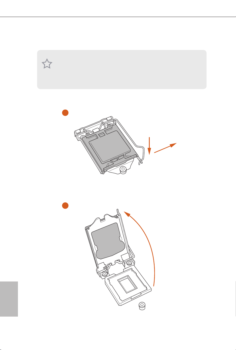
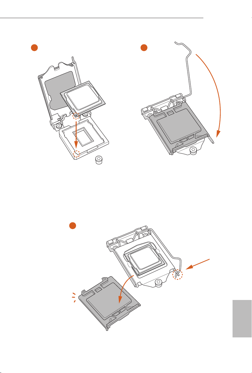
2.1 Installing the CPU
1. Before you insert the 1151-Pin CPU into the socket, please check if the PnP c ap
is on the socket, if the CPU sur face is unclean, or if there are any b ent pins in the
socket. Do not force to insert the CPU into the socket if above situation is found.
Other wise, the CPU will be seriously d amaged.
2. Unplug all power cables be fore installing the CPU.
1
2
A
B
English
10
Page 13
E3V5 WS
3
4
5
English
11
Page 14

Please save and replace the cover if the processor i s removed. e cover must be
placed if you wish to return the motherboard for aer service.
English
12
Page 15

2.2 Installing the CPU Fan and Heatsink
1 2
E3V5 WS
FAN
CPU_
English
13
Page 16

2.3 Installing Memory Modules (DIMM)
is motherboard provides four 288-pin DDR4 (Double Data Rate 4) DIMM slots,
and supports Dual Channel Memory Technology.
1. For dual channel conguration, you always need to install identical (the same
brand, speed , size and chip-type) DDR4 DIMM pairs.
2. It is unable to activate Dual Channel Memor y Technolog y with only one or three
memory module installed.
3. It is not allowed to install a DDR, DDR2 or DDR3 memory module into a DDR4
slot; otherwise, this motherboard and DIMM may be damaged.
Dual Channel Memory Conguration
Priority DDR4_ A1 DDR4_ A2 DDR4_B1 DDR4_B2
1 Populated Populated
2 Populated Populated
3 Populated Populated Populated Populated
e DIMM only ts in one correct orientation. It will cause permanent damage to
the mothe rboard and the DIMM if you force the DIMM into the slot at incor rect
orientation.
English
14
Page 17

E3V5 WS
1
2
3
English
15
Page 18

2.4 Expansion Slots (PCI Express Slots)
ere are 5 PCI Express slots on the motherboard.
Before installing an ex pansion card, please make sure that the power supply is
switched o or the power cord is unplugged. Plea se read the documentation of the
expan sion card and make necessary hardware settings for the card before you start
the installation.
PCIe slots:
PCIE1 (PCIe 3.0 x1 slot) is used for PCI Express x1 lane width cards.
PCIE2 (PCIe 3.0 x16 slot) is used for PCI Express x16 lane width graphics cards.
PCIE3 (PCIe 3.0 x1 slot) is used for PCI Express x1 lane width cards.
PCIE4 (PCIe 3.0 x16 slot) is used for PCI Express x4 lane width graphics cards.
PCIE5 (PCIe 3.0 x1 slot) is used for PCI Express x1 lane width cards.
PCIe Slot Congurations
PCIE2 PCIE4
Single Graphics Card x16 N/A
English
16
Two Graphics Cards in
CrossFireXTM Mode
For a better ther mal environment, please connect a chassi s fan to the motherboard’s
chassis fan connector (CHA_ FAN1 or CHA_ FAN2) when using multiple graphics
cards.
x16 x4
Page 19

2.5 Jumpers Setup
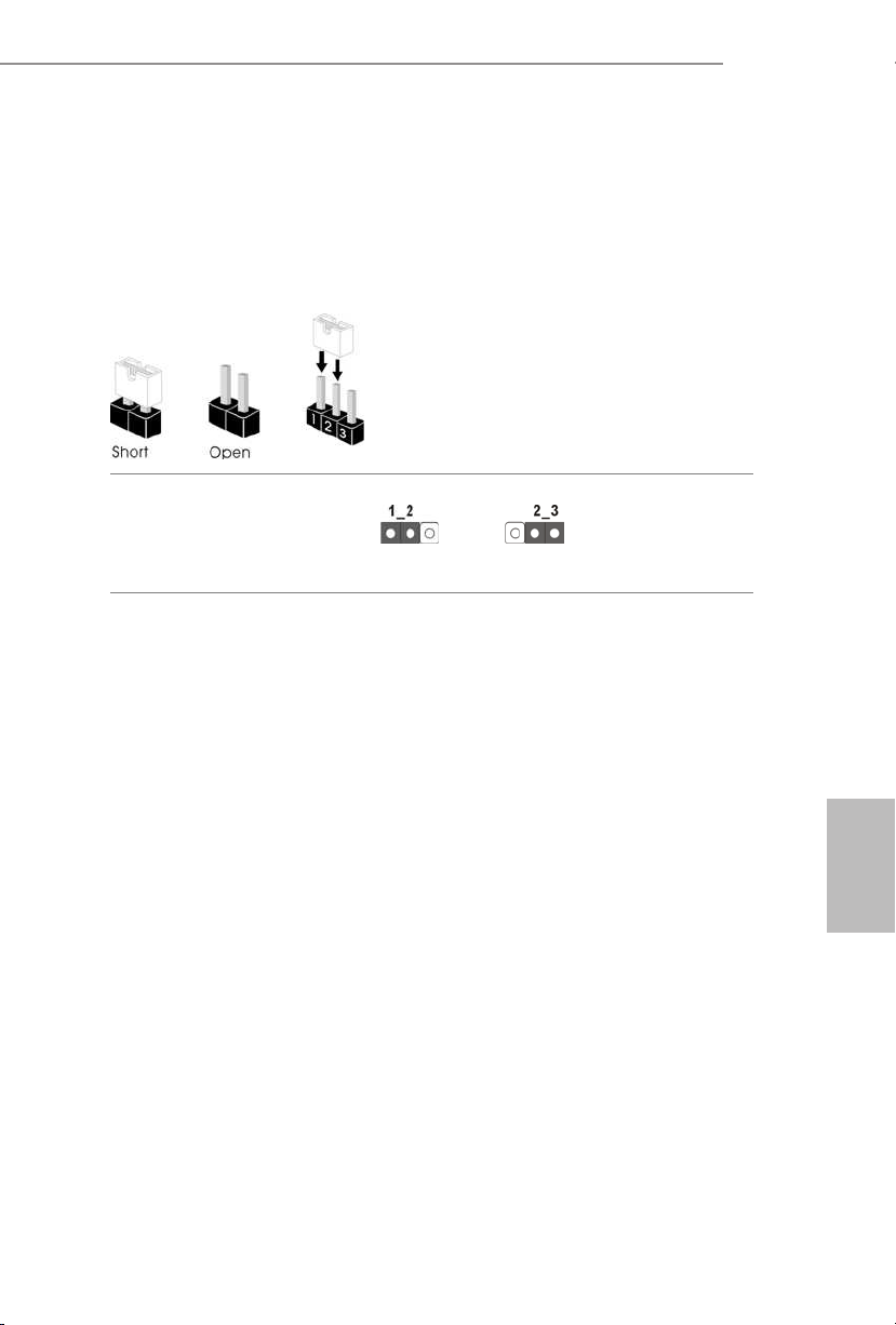
e illustration shows how jumpers are setup. When the jumper cap is placed on
the pins, the jumper is “Short”. If no jumper cap is placed on the pins, the jumper
is “Open”. e illustration shows a 3-pin jumper whose pin1 and pin2 are “Short”
when a jumper cap is placed on these 2 pins.
Clear CMOS Jumper
(CLRMOS1)
(see p.1, No. 8)
CLRMOS1 allows you to clear the data in CMOS. To clear and reset the system
parameters to default setup, please turn o the computer and unplug the power
cord from the power supply. Aer waiting for 15 seconds, use a jumper cap to
short pin2 and pin3 on CLRMOS1 for 5 seconds. However, please do not clear the
CMOS right aer you update the BIOS. If you need to clear the CMOS when you
just nish updating the BIOS, you must boot up the system rst, and then shut it
down before you do the clear-CMOS action. Please be noted that the password,
date, time, and user default prole will be cleared only if the CMOS battery is
removed.
Clear CMOSDefault
E3V5 WS
17
English
Page 20

2.6 Onboard Headers and Connectors
Onboard headers and connectors are NOT jumpers. Do NOT place jumper caps over
these headers and connectors. Placing jumper caps over the headers and connectors
will cause permanent damage to the motherboard.
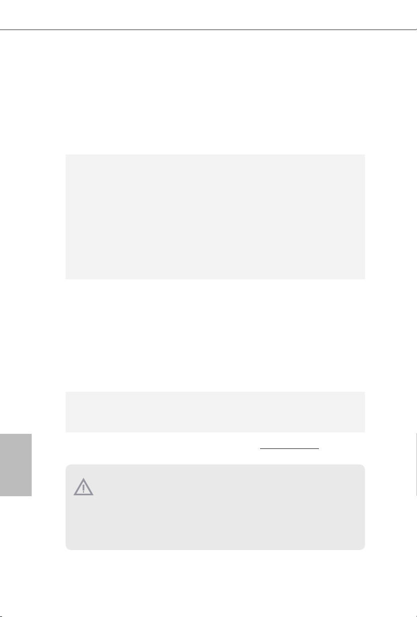
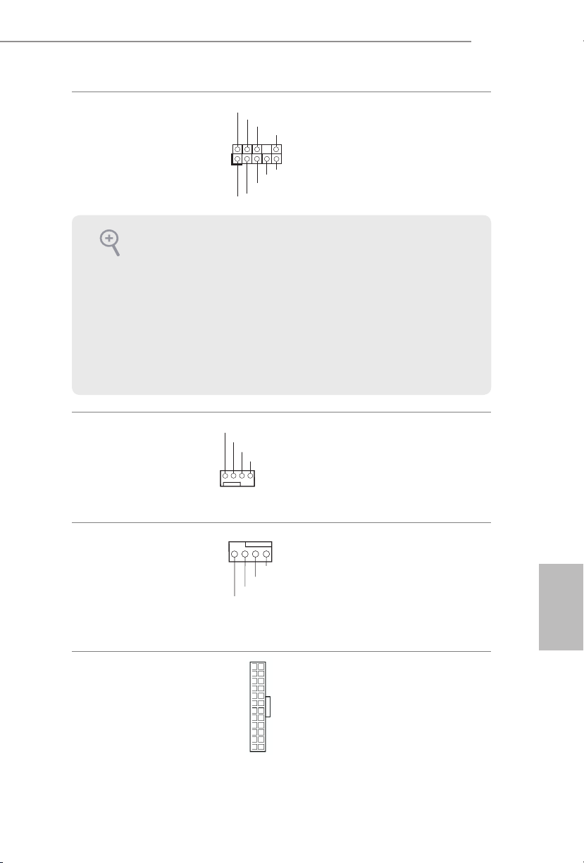
System Panel Header
(9-pin PANEL1)
(see p.1, No. 13)
PWRBTN (Power Switch):
Connec t to the power switch on the chassi s front panel. You may congure the way to
turn o your system using the power switch.
RESET (Reset Switch):
Connec t to the reset switch on the chassis front panel. Press the reset sw itch to restart
the computer if the compute r freezes and fails to perform a normal restart.
PLED (Syste m Power LED):
Connec t to the power status indicator on the chassis front panel. e LED i s on when
the system is ope rating. e LED keeps blinking when the system i s in S1/S3 sleep
state. e LED is o when the system is in S4 sleep state or powered o (S5).
HDLED (Ha rd Drive Activity LED):
Connec t to the hard drive activity LED on the chassis front panel. e LED is on
when the hard drive i s reading or writing data.
e front panel design may dier by chassis. A front panel module mainly consists
of power switch, reset switch, power LED, hard dr ive activity LED, speak er and etc.
When connecting your chassis front panel module to this head er, make sure the wire
assig nments and the pin assig nments are matched correctly.
1
PLE D+
PLE D-
HDL ED-
HDL ED+
PWR BTN#
GND
RES ET#
GND
GND
Connect the power
switch, reset switch and
system status indicator on
the chassis to this header
according to the pin
assignments below. Note
the positive and negative
pins before connecting
the cables.
English
18
Page 21

E3V5 WS
PLE D-
IntA _P_ D+
Power LED and Speaker
Header
(7-pin SPK_PLED1)
(see p.1, No. 11)
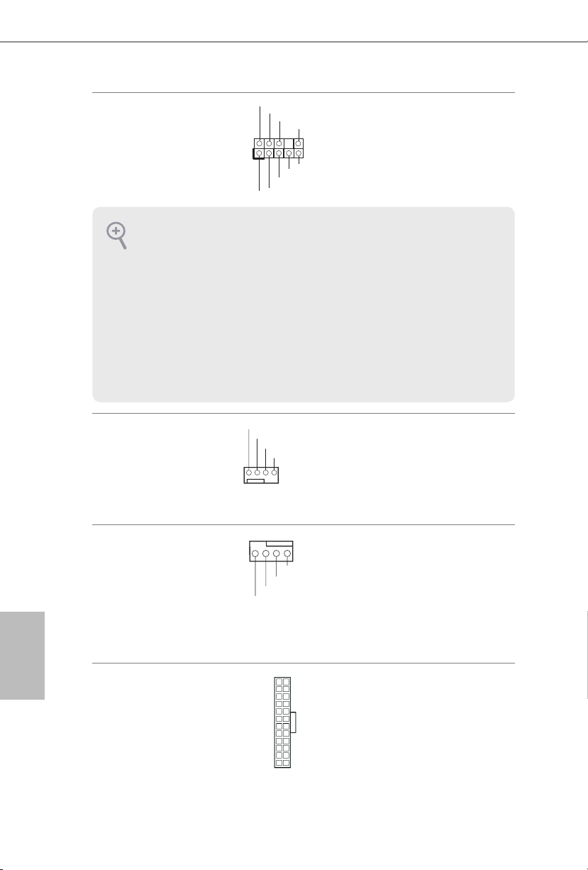
Serial ATA3 Connectors
(SATA3_0:
see p.1, No. 12)
(SATA3_1:
see p.1, No. 14)
(SATA3_2:
see p.1, No. 9)
(SATA3_3:
see p.1, No. 15)
(SATA3_4:
see p.1, No. 17)
(SATA3_5:
see p.1, No. 16)
USB 2.0 Headers
(9-pin USB2_3)
(see p.1, No. 18)
(9-pin USB4_5)
(see p.1, No. 19)
DUM MY
+5V
1
PLE D+
SATA3_2SATA3_4
SATA3_3SATA3_5
USB _PWR
1
USB _PWR
SPE AKER
DUM MY
PLE D+
P-
P+
P+
P-
GND
GND
DUM MY
SATA3_0
SATA3_1
Please connect the
chassis power LED and
the chassis speaker to this
header.
ese six SATA3
connectors support SATA
data cables for internal
storage devices with up to
6.0 Gb/s data transfer rate.
ere are two headers
on this motherboard.
Each USB 2.0 header can
support two ports.
USB 3.0 Header
(19-pin USB3_4_5)
(see p.1, No. 6)
1
IntA _P_ D-
IntA _P_ D+
ID
GND
IntA _P_ SSTX +
IntA _P_ SSTX -
IntA _P_ SSTX +
GND
IntA _P_ D-
GND
IntA _P_ SSRX +
IntA _P_ SSR X-
IntA _P_ SSRX +
GND
IntA _P_ SSTX -
Vbus
Vbus
IntA _P_ SSR X-
Besides four USB 3.0
ports on the I/O panel,
there is one header on this
motherboard. Each USB
3.0 header can support
two ports.
English
19
Page 22

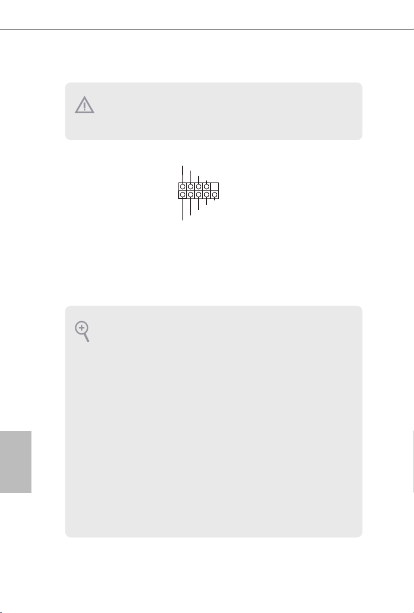
Front Panel Audio Header
(9-pin HD_AUDIO1)
(see p.1, No. 21)
1. High Denition Audio supports Jack Sensing, but the panel wire on the chassis
must support HDA to function correctly. Please follow the instructions in our
manual and chassis manual to install your system.
2. If you use an AC’97 audio panel, please install it to the front panel audio heade r by
the steps below:
A. Connect Mic_IN (MIC) to MIC2_ L.
B. Conne ct Audio_R (RIN) to OUT2_R and Audio_ L (LIN) to OUT2_ L.
C. Connect Ground (GND) to Ground (GND).
D. MIC_ RET and OUT_RET are for the HD audio panel only. You don’t need to
connect them for the AC’97 audio panel.
E. To activate the front mic, go to the “FrontMic” Tab in the Realtek Control panel
and adju st “Recording Volume”.
1
GND
PRE SENCE #
MIC 2_R
MIC 2_L
MIC _RET
J_S ENSE
OUT 2_R
OUT _RET
OUT 2_L
is header is for
connecting audio devices
to the front audio panel.
English
20
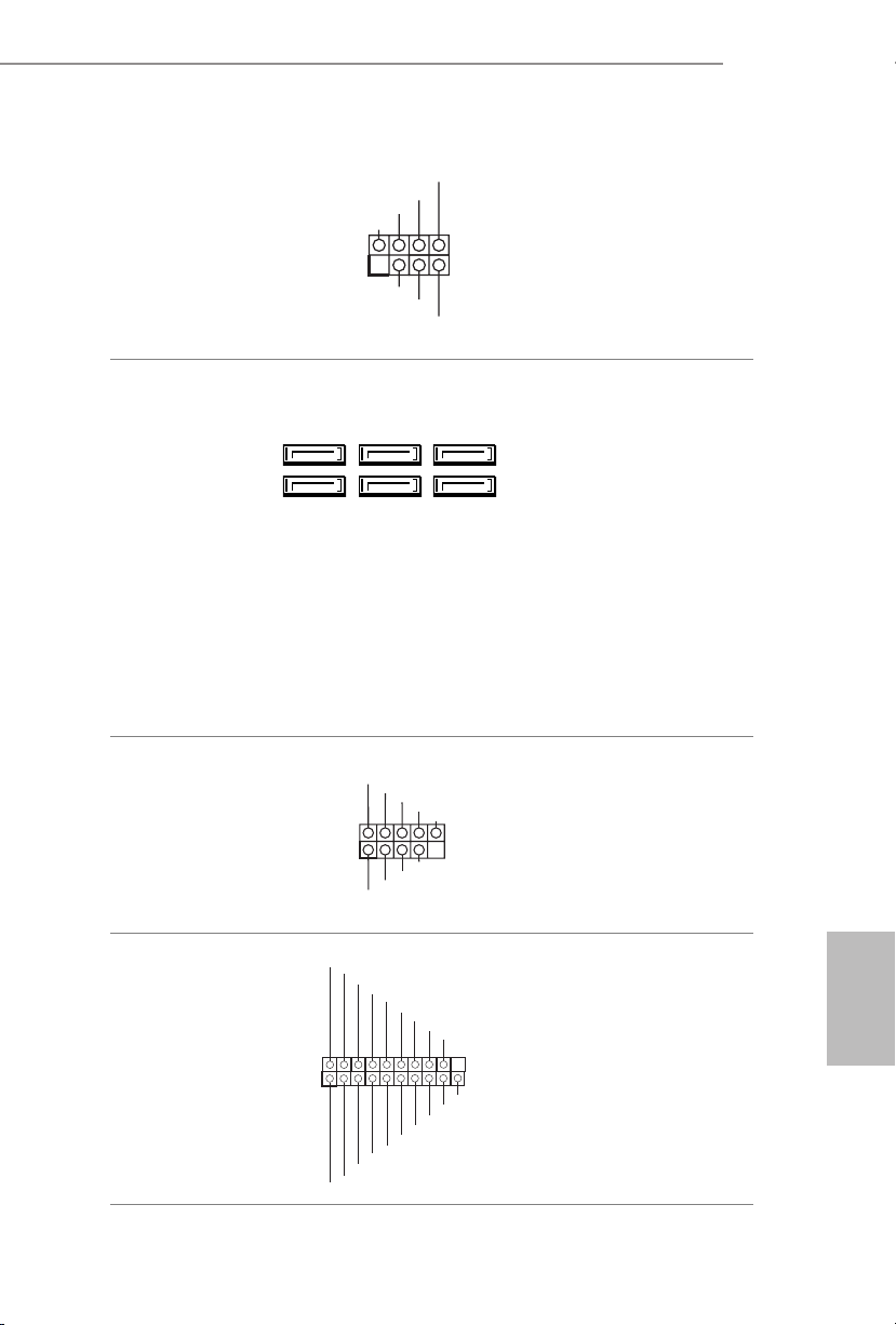
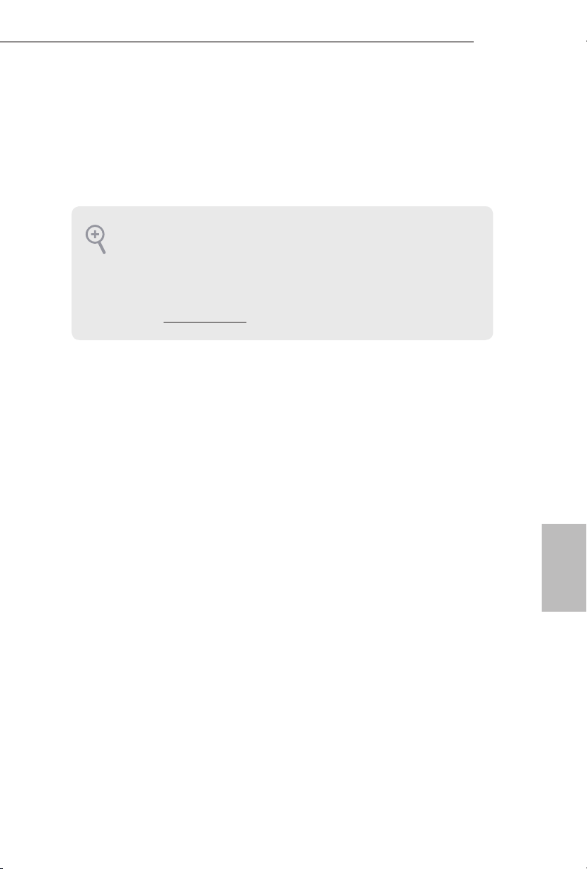
Chassis Fan Connectors
(4-pin CHA_FAN1)
(see p.1, No. 7)
(4-pin CHA_FAN2)
(see p.1, No. 10)
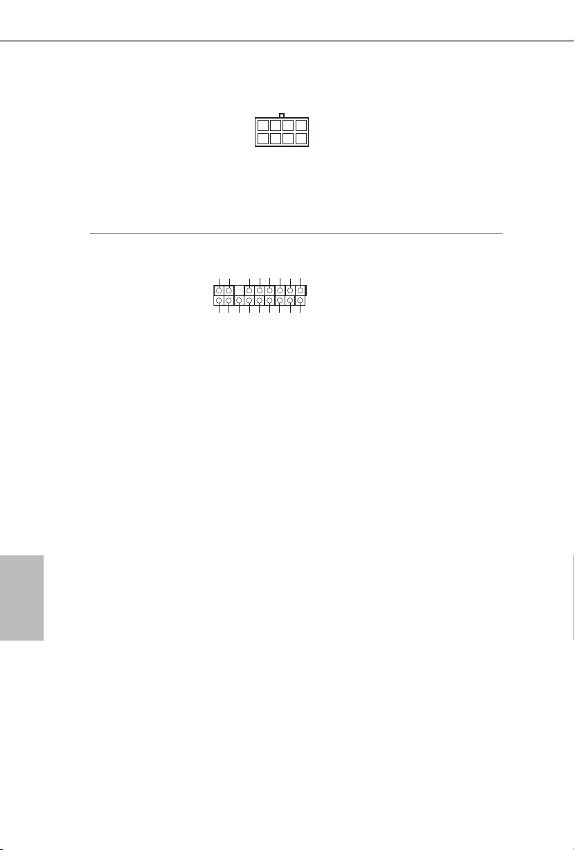
CPU Fan Connector
(4-pin CPU_FAN1)
(see p.1, No. 2)
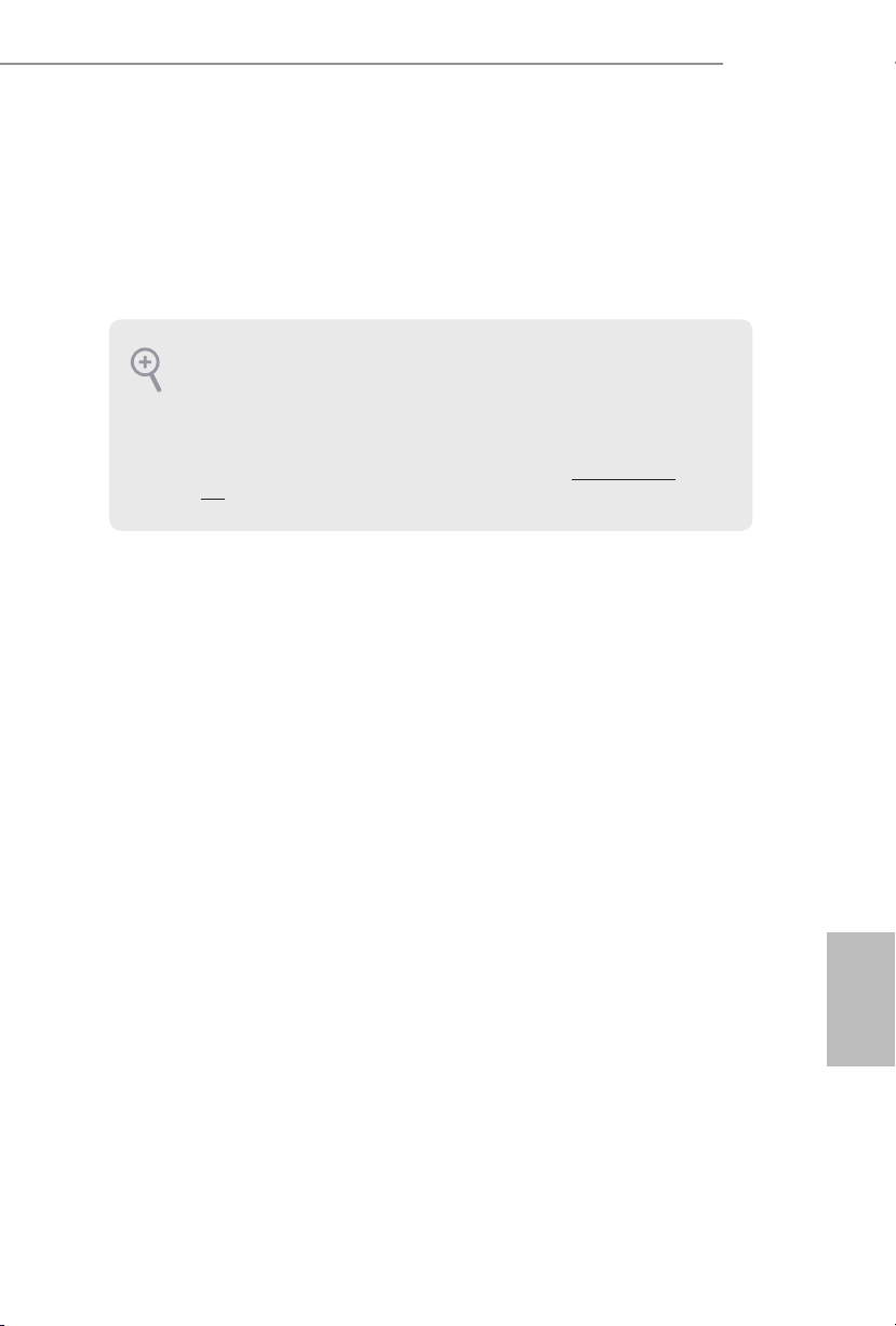
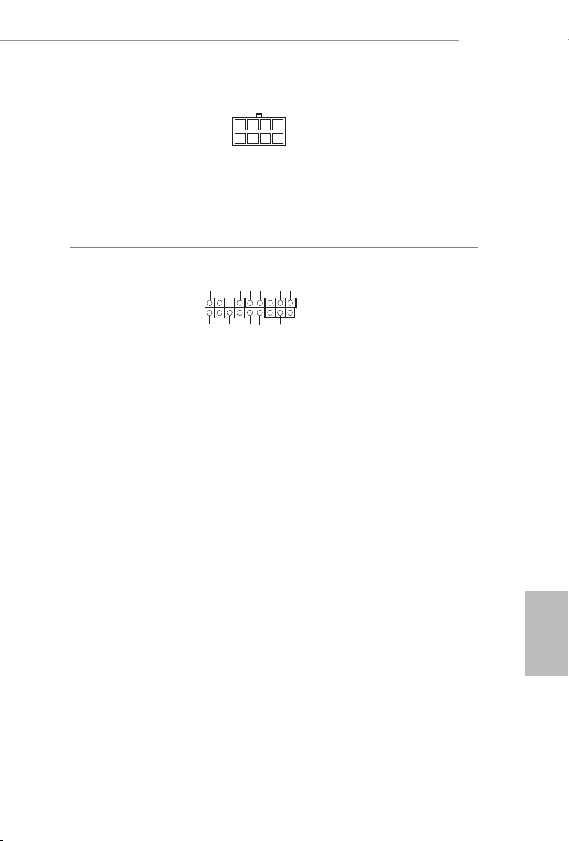
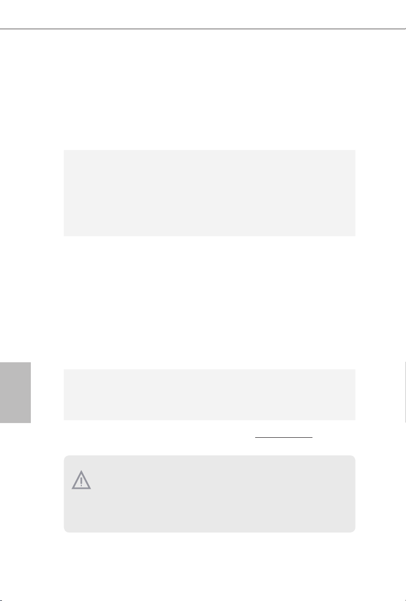
ATX Power Connector
(24-pin ATXPWR1)
(see p.1, No. 5)
GND
FAN _VO LTA GE
CHA _FA N_S PEE D
FAN _SP EED _CO NTR OL
4 3 2 1
GND
FAN _VOLT AGE
CPU _F
AN_ SPEED
FAN_ SPEED _CONT ROL
24
12
1
13
Please connect fan cables
to the fan connectors and
match the black wire to
the ground pin.
is motherboard provides a 4-Pin CPU fan
(Quiet Fan) connector.
If you plan to connect a
3-Pin CPU fan, please
connect it to Pin 1-3.
is motherboard provides a 24-pin ATX power
connector. To use a 20-pin
ATX power supply, please
plug it along Pin 1 and Pin
13.
Page 23

E3V5 WS
1
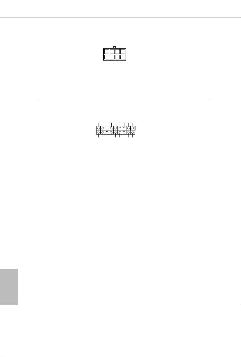
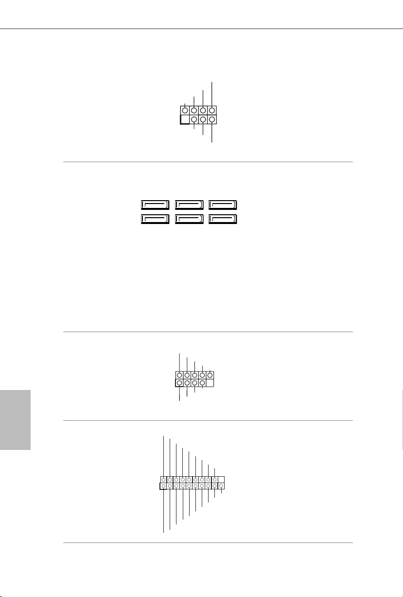
ATX 12V Power
Connector
(8-pin ATX12V1)
(see p.1, No. 1)
TPM Header
(17-pin TPMS1)
(see p.1, No. 20)
8
5
is motherboard provides an 8-pin ATX 12V
power connector. To use a
4-pin ATX power supply,
please plug it along Pin 1
and Pin 5.
is connector supports Trusted
GN D
LAD 0
+3 V
+3V S B
D
GN
GN D
LAD 1
SER IRQ #
S_P WRD WN #
PC ICL K
LAD 3
PC IRS T #
FRA M E
GN D
LAD 2
Platform Module (TPM) system,
1
which can securely store keys,
digital certicates, passwords,
and data. A TPM system also
helps enhance network security,
SMB _CL K_MA IN
SMB _DA TA_M AIN
protects digital identities, and
ensures platform integrity.
English
21
Page 24

1 Einleitung
Vielen Dank, dass Sie sich für das E3V5 WS von ASRock entschieden haben – ein
zuverlässiges Motherboard, das konsequent unter der strengen Qualitätskontrolle von
ASRock hergestellt wurde. Es liefert ausgezeichnete Leistung mit robustem Design,
das ASRock Streben nach Qualität und Beständigkeit erfüllt.
Da die technischen Daten des Motherboards sowie die BIOS-Soware aktualisiert
werden können, kann der Inhalt dieser Dokumentation ohne Ankündigung geändert
werden. Falls diese Dokumentation irgendwelchen Änderungen unterliegt, wird die aktualisierte Version ohne weitere Hinweise auf der ASRock-Webseite zur Verfügung gestellt.
Sollten Sie technische Hilfe in Bezug auf dieses Motherboard benötigen, erhalten Sie auf
unserer Webseite spezischen Informationen über das von Ihnen verwendete Modell.
Auch nden Sie eine aktuelle Liste unterstützter VGA-Karten und Prozessoren auf der
ASRock-Webseite:
ASRock-Website http://www.asrock.com.
1.1 Lieferumfang
•ASRock E3V5 WS-Motherboard (ATX-Formfaktor)
•ASRock E3V5 WS-Schnellinstallationsanleitung
•ASRock E3V5 WS-Unterstützungs-CD
•2 x Serial-ATA- (SATA) Datenkabel (optional)
•1 x E/A-Blendenabschirmung
Deutsch
22
Page 25

1.2 Technische Daten
E3V5 WS
Plattform
Prozessor
Chipsatz
Speicher
Erweiterungssteckplatz
•ATX-Formfaktor
•Feststoondensator-Design
•Unterstützt die Prozessoren Intel® Xeon E3-1200 v5 und
Prozessoren Intel® CoreTM i7/i5/i3/Pentium®/Celeron® der 6.
Generation (Sockel 1151)
•5-Leistungsphasendesign
•Unterstützt Intel® Turbo Boost 2.0-Technologie
•Intel® C232
•Dualkanal-DDR4-Speichertechnologie
•4 x DDR4-DIMM-Steckplätze
•Unterstützt DDR4 2133 non-ECC, ungepuerter Speicher
•Unterstützt ECC-UDIMM-Speichermodule
* ECC wird nur mit Intel® E3/CoreTM i3/Pentium®/Celeron®-Prozessor
unterstützt. Intel® CoreTM i7/i5-Prozessor unterstützt nicht die ECC.
•Systemspeicher, max. Kapazität: 64GB
•Unterstützt Intel® Extreme Memory Prole (XMP) 2.0
•15-μ-Goldkontakt in DIMM-Steckplätze
•2 x PCI-Express 3.0-x16-Steckplätze (PCIE2:
PCIE4: x4-Modus)*
* Unterstützt NVMe-SSD als Bootplatte
•3 x PCI-Express 3.0-x1-Steckplätze (Flexible PCIe)
•Unterstützt AMD Quad CrossFireX
•15-μ-Goldkontakt in VGA-PCIe-Steckplatz (PCIE2)
TM
x16-Modus;
und CrossFireX
TM
Audio
•7.1-Kanal-HD-Audio mit Inhaltsschutz (Realtek ALC892-
Audiocodec)
* Zur Konguration von 7.1-Kanal-HD-Audio müssen Sie ein HDFrontblenden-Audiomodul nutzen und den Mehrkanalton über
den Audiotreiber aktivieren.
•Erstklassige Blu-ray-Audiounterstützung
•Unterstützt Überspannungsschutz (ASRock Full Spike
Protection)
•ELNA-Audiokondensatoren
Deutsch
23
Page 26

LAN
•Gigabit LAN 10/100/1000 Mb/s
•Giga PHY Intel® I219LM
•Unterstützt Wake-On-LAN
•Unterstützt Blitzschutz/Schutz gegen elektrostatische Entla-
dung (ASRock Full Spike Protection)
•Unterstützt energieezientes Ethernet 802.3az
•Unterstützt PXE
Deutsch
Rückblende,
E/A
Speicher
Anschluss
•1 x PS/2-Mausanschluss
•1 x PS/2-Tastaturanschluss
•2 x USB 2.0-Ports (unterstützt Schutz gegen elektrostatische
Entladung (ASRock Full Spike Protection))
•4 x USB 3.0-Ports (unterstützt Schutz gegen elektrostatische
Entladung (ASRock Full Spike Protection))
•1 x RJ-45-LAN-Port mit LED (Aktivität/Verbindung-LED und
Geschwindigkeit-LED)
•HD-Audioanschlüsse: Line-in / Vorderer Lautsprecher /
Mikrofon
•6 x SATA-III-6,0-Gb/s-Anschlüsse, unterstützt RAID (RAID 0,
RAID 1, RAID 5, RAID 10, Intel RSTe), NCQ, AHCI und HotPlugging
•1 x TPM-Stileiste
•1 x Betrieb-LED- und Lautsprecher-Stileiste
•1 x CPU-Lüeranschluss (4-polig) (intelligente
Lüergeschwindigkeitssteuerung)
•2 x Gehäuselüeranschlüsse (4-polig) (intelligente
Lüergeschwindigkeitssteuerung
•1 x 24-poliger ATX-Netzanschluss
•1 x 8-poliger 12-V-Netzanschluss
•1 x Audioanschluss an Frontblende
•2 x USB 2.0-Stileisten (unterstützen 4 USB 2.0-Ports)
(unterstützt Schutz gegen elektrostatische Entladung (ASRock
Full Spike Protection))
•1 x USB 3.0-Stileiste (unterstützt 2 USB 3.0-Ports)
(unterstützt Schutz gegen elektrostatische Entladung (ASRock
Full Spike Protection))
24
Page 27

E3V5 WS
BIOSFunktion
Hardwareüberwachung
Betriebssystem
Zertizierungen
•AMI-UEFI-Legal-BIOS mit Unterstützung mehrsprachiger
grascher Benutzerschnittstellen
•ACPI 5
0-konforme Aufweckereignisse
.
•SMBIOS 2.7-Unterstützung
•CPU, DRAM, VPPM, PCH 1,0V, VCCIO, VCCSA Mehrfach-
spannungsanpassung
•CPU-/Gehäusetemperaturerkennung
•CPU-/Gehäuselüertachometer
•Lautloser CPU-/Gehäuselüer (automatische Anpassung der
Gehäuselüergeschwindigkeit durch CPU-Temperatur)
•CPU-/Gehäuselüer-Mehrfachgeschwindigkeitssteuerung
•Spannungsüberwachung: +12 V, +5 V, +3,3 V, CPU Vcore
•Microso® Windows® 10, 64 Bit / 8.1, 64 Bit / 7, 32 Bit / 7, 64
Bit / Server 2012 R2, 64 Bit / Server 2012, 64 Bit / Server 2008
R2, 64 Bit
* Zur Installation des Windows® 7-Betriebssystems wird ein
modiziertes Installationslaufwerk mit xHCI-Treibern in der
ISO-Datei benötigt. Detaillierte Anweisungen nden Sie auf
Seite 125.
* Einzelheiten zum aktualisierten Windows® 10-Treiber
entnehmen Sie bitte der ASRock-Webseite: http://www.asrock.com
•FCC, CE, WHQL
•ErP/EuP ready (ErP/EuP ready-Netzteil erforderlich)
* Detaillierte Produktinformationen nden Sie auf unserer Webseite: http://www.asrock.com
Bitte beachten Sie, dass mit einer Übertaktung, zu der die Anpassung von BIOSEinstellungen, die Anwendung der Untied Overclocking Technology oder die Nutzung
von Übertaktungswerkzeugen von Drittanbietern zählen, bestimmte Risiken verbunden
sind. Eine Übertaktung kann sich auf die Stabilität Ihres Systems auswirken und sogar
Komponenten und Geräte Ihres Systems beschädigen. Sie sollte auf eigene Gefahr und
eigene Kosten durchgeführt werden. Wir übernehmen keine Verantwortung für mögliche
Schäden, die durch eine Übertaktung verursacht wurden.
Deutsch
25
Page 28

1.3 Jumpereinstellung
Die Abbildung zeigt, wie die Jumper eingestellt werden. Wenn die Jumper-Kappe auf
den Kontakten angebracht ist, ist der Jumper „kurzgeschlossen“. Wenn keine JumperKappe auf den Kontakten angebracht ist, ist der Jumper „oen“. Die Abbildung zeigt
einen 3-poligen Jumper, dessen Kontakt 1 und Kontakt 2 „kurzgeschlossen“ sind,
wenn eine Jumper-Kappe auf diesen 2 Kontakten angebracht ist.
CMOS-löschen-Jumper
(CLRMOS1)
(siehe S. 1, Nr. 8)
CLRMOS1 ermöglicht Ihnen die Löschung der Daten im CMOS. Zum Löschen
und Rücksetzen der Systemparameter auf die Standardeinrichtung schalten Sie
den Computer bitte ab und ziehen das Netzkabel aus der Steckdose. Warten Sie 15
Sekunde, schließen Sie dann Kontakt 2 und Kontakt 3 an CLRMOS1 5 Sekunden
lang mit einer Jumper-Kappe kurz. Löschen Sie den CMOS jedoch nicht direkt nach
der BIOS-Aktualisierung. Falls Sie den CMOS direkt nach Abschluss der BIOSAktualisierung löschen müssen, starten Sie das System zunächst; fahren Sie es dann
vor der CMOS-Löschung herunter. Bitte beachten Sie, dass Kennwort, Datum, Zeit
und Benutzerstandardprol nur gelöscht werden, wenn die CMOS-Batterie entfernt
wird.
CMOS löschenStandard
Deutsch
26
Page 29

1.4 Integrierte Stiftleisten und Anschlüsse
Integrierte Stileisten und Anschlüsse sind KEINE Jumper. Bringen Sie KEINE JumperKappen an diesen Stileisten und Anschlüssen an. Durch Anbringen von JumperKappen an diesen Stileisten und Anschlüssen können Sie das Motherboard dauerha
beschädigen.
E3V5 WS
Systemblende-Stileiste
(9-polig, PANEL1)
(siehe S. 1, Nr. 13)
PWRBTN (Ein-/Austaste):
Mit der Ein-/Austaste an der Frontblende des Gehäuses verbinden. Sie können die
Abschaltung Ihres Systems über die Ein-/Austaste kongurieren.
RESET (Reset-Taste):
Mit der Reset-Taste an der Frontblende des Gehäuses verbinden. Starten Sie den Computer über die Reset-Taste neu, wenn er abstürzt oder sich nicht normal neu starten lässt.
PLED (Systembetriebs-LED):
Mit der Betriebsstatusanzeige an der Frontblende des Gehäuses verbinden. Die LED
leuchtet, wenn das System läu. Die LED blinkt, wenn sich das System im S1/S3-Ruhezustand bendet. Die LED ist aus, wenn sich das System im S4-Ruhezustand bendet
oder ausgeschaltet ist (S5).
HDLED (Festplattenaktivitäts-LED):
Mit der Festplattenaktivitäts-LED an der Frontblende des Gehäuses verbinden. Die LED
leuchtet, wenn die Festplatte Daten liest oder schreibt.
Das Design der Frontblende kann je nach Gehäuse variieren. Ein Frontblendenmodul
besteht hauptsächlich aus Ein-/Austaste, Reset-Taste, Betrieb-LED, FestplattenaktivitätLED, Lautsprecher etc. Stellen Sie beim Anschließen Ihres Frontblendenmoduls an diese
Stileiste sicher, dass Kabel- und Pinbelegung richtig abgestimmt sind.
1
PLE D+
PLE D-
HDL ED-
HDL ED+
PWR BTN#
GND
RES ET#
GND
GND
Verbinden Sie
Netzschalter, Reset-Taste
und Systemstatusanzeige
am Gehäuse entsprechend
der nachstehenden
Pinbelegung mit dieser
Stileiste. Beachten Sie vor
Anschließen der Kabel die
positiven und negativen
Kontakte.
27
Deutsch
Page 30

Betrieb-LED- und
PLE D-
IntA _P_ D+
Lautsprecher-Stileiste
(7-polig, SPK_PLED1)
(siehe S. 1, Nr. 11)
DUM MY
+5V
1
PLE D+
SPE AKER
DUM MY
PLE D+
Bitte verbinden Sie
die Betrieb-LED des
Gehäuses und den
Gehäuselautsprecher mit
dieser Stileiste.
Deutsch
Serial-ATA-III-Anschlüsse
(SATA3_0:
siehe S. 1, Nr. 12)
(SATA3_1:
siehe S. 1, Nr. 14)
(SATA3_2:
siehe S. 1, Nr. 9)
(SATA3_3:
siehe S. 1, Nr. 15)
(SATA3_4:
siehe S. 1, Nr. 17)
(SATA3_5:
siehe S. 1, Nr. 16)
USB 2.0-Stileisten
(9-polig, USB2_3)
(siehe S. 1, Nr. 18)
(9-polig, USB4_5)
(siehe S. 1, Nr. 19)
USB 3.0-Stileiste
(19-polig, USB3_4_5)
(siehe S. 1, Nr. 6)
1
IntA _P_ D-
IntA _P_ D+
ID
SATA3_2SATA3_4
SATA3_3SATA3_5
USB _PWR
1
USB _PWR
GND
IntA _P_ SSTX +
GND
IntA _P_ D-
P-
P+
GND
GND
P+
P-
IntA _P_ SSTX -
GND
IntA _P_ SSRX +
GND
IntA _P_ SSTX -
IntA _P_ SSTX +
SATA3_0
SATA3_1
DUM MY
IntA _P_ SSR X-
Vbus
Vbus
IntA _P_ SSR X-
IntA _P_ SSRX +
Diese sechs SATA-IIIAnschlüsse unterstützen
SATA-Datenkabel für
interne Speichergeräte mit
einer Datenübertragungsg
eschwindigkeit bis 6,0 Gb/
s.
Es gibt zwei Stileisten an
diesem Motherboard. Jede
USB 2.0-Stileiste kann
zwei Ports unterstützen.
Neben vier USB 3.0-Ports
an der E/A-Blende bendet
sich eine Stileiste an
diesem Motherboard. Jede
USB 3.0-Stileiste kann
zwei Ports unterstützen.
28
Page 31

E3V5 WS
4 3 2 1
Audiostileiste
(Frontblende)
(9-polig, HD_AUDIO1)
(siehe S. 1, Nr. 21)
1. High Denition Audio unterstützt Anschlusserkennung, der Draht am Gehäuse muss
dazu jedoch HDA unterstützt. Bitte befolgen Sie zum Installieren Ihres Systems die
Anweisungen in unserer Anleitung und der Anleitung zum Gehäuse.
2. Bei Nutzung eines AC’97-Audiopanels dieses bitte anhand folgender Schritte an der
Audiostileiste der Frontblende installieren:
A. Mic_IN (Mikrofon) mit MIC2_L verbinden.
B. Audio_R (RIN) mit OUT2_R und Audio_L (LIN) mit OUT2_L verbinden.
C. Erde (GND) mit Erde (GND) verbinden.
D. MIC_RET und OUT_RET sind nur für das HD-Audiopanel vorgesehen. Sie müssen
sie nicht für das AC’97-Audiopanel verbinden.
E. Rufen Sie zum Aktivieren des vorderen Mikrofons das „FrontMic (Vorderes
Mikrofon)“-Register in der Realtek-Systemsteuerung auf und passen „Recording
Volume (Aufnahmelautstärke)“ an.
Gehäuselüeranschlüsse
(4-polig, CHA_FAN1)
(siehe S. 1, Nr. 7)
(4-polig, CHA_FAN2)
(siehe S. 1, Nr. 10)
GND
1
MIC 2_L
GND
FAN _VO LTA GE
CHA _FA N_S PEE D
PRE SENCE #
MIC _RET
OUT _RET
OUT 2_L
J_S ENSE
OUT 2_R
MIC 2_R
FAN _SP EED _CO NTR OL
Diese Stileiste dient
dem Anschließen von
Audiogeräten an der
Frontblende.
Bitte verbinden Sie die
Lüerkabel mit den
Lüeranschlüssen; der
schwarze Draht gehört zum
Erdungskontakt.
CPU-Lüeranschlüsse
(4-polig, CPU_FAN1)
(siehe S. 1, Nr. 2)
ATX-Netzanschluss
(24-polig, ATXPWR1)
(siehe S. 1, Nr. 5)
GND
FAN _VOLT AGE
CPU _F
AN_ SPEED
FAN_ SPEED _CONT ROL
24
12
1
13
Dieses Motherboard
bietet einen 4-poligen
CPU-Lüeranschluss
(lautloser Lüer). Falls Sie
einen 3-poligen CPU-Lüer
anschließen möchten,
verbinden Sie ihn bitte mit
Kontakt 1 bis 3.
Dieses Motherboard bietet
einen 24-poligen ATX-Netzanschluss. Bitte schließen
Sie es zur Nutzung eines
20-poligen ATX-Netzteils
entlang Kontakt 1 und Kontakt 13 an.
Deutsch
29
Page 32
ATX-12-V-Netzanschluss
1
(8-polig, ATX12V1)
(siehe S. 1, Nr. 1)
8
5
Dieses Motherboard bietet
einen 8-poligen ATX-12V-Netzanschluss. Bitte
schließen Sie es zur Nutzung eines 4-poligen ATXNetzteils entlang Kontakt 1
und Kontakt 5 an.
Deutsch
TPM-Stileiste
(17-polig, TPMS1)
(siehe S. 1, Nr. 20)
Dieser Anschluss unterstützt das
Trusted Platform Module- (TPM)
GN D
LAD 0
+3 V
+3V S B
D
GN
GN D
LAD 1
SER IRQ #
S_P WRD WN #
PC ICL K
LAD 3
PC IRS T #
LAD 2
System, das Schlüssel, digitale
FRA M E
1
Zertikate, Kennwörter und
Daten sicher auewahren kann.
GN D
Ein TPM-System hil zudem bei
der Stärkung der Netzwerksicher-
SMB _CL K_MA IN
SMB _DA TA_M AIN
heit, schützt digitale Identitäten
und gewährleistet die Plattformintegrität.
30
Page 33
1 Introduction
Nous vous remercions d’avoir acheté cette carte mère ASRock E3V5 WS, une carte
mère able fabriquée conformément au contrôle de qualité rigoureux et constant
appliqué par ASRock. Fidèle à son engagement de qualité et de durabilité, ASRock
vous garantit une carte mère de conception robuste aux performances élevées.
Les spécications de la carte mère et du logiciel BIOS pouvant être mises à jour, le
contenu de ce document est soumis à modication sans préavis. En cas de modications
du présent document, la version mise à jour sera disponible sur le site Internet ASRock
sans notication préalable. Si vous avez besoin d’une assistance technique pour votre
carte mère, veuillez visiter notre site Internet pour plus de détails sur le modèle que vous
utilisez. La liste la plus récente des cartes VGA et des processeurs pris en charge est également disponible sur le site Internet de ASRock. Site Internet ASRock http://www.asrock.
com.
1.1 Contenu de l’emballage
•Carte mère ASRock E3V5 WS (facteur de forme ATX)
•Guide d’installation rapide ASRock E3V5 WS
•CD d’assistance ASRock E3V5 WS
•2 x câbles de données Serial ATA (SATA) (Optionnel)
•1 x panneau de protection E/S
E3V5 WS
31
Français
Page 34

1.2 Spécications
Français
Plateforme
Processeur
Chipset
Mémoire
Fente
d’expansion
Audio
•Facteur de forme ATX
•Conception à condensateurs solides
•Prend en charge les processeurs Intel® Xeon® E3-1200 v5 et
les processeurs 6e génération Intel® CoreTM i7/i5/i3/Pentium®/
Celeron® (Socket 1151)
•Alimentation à 5 phases
•Prend en charge la technologie Intel® Turbo Boost 2.0
•Intel® C232
•Technologie mémoire double canal DDR4
•4 x fentes DIMM DDR4
•Prend en charge les mémoires sans tampon non ECC DDR4
2133
•Prend en charge les modules mémoire UDIMM ECC
* ECC est uniquement pris en charge le processeur Intel® E3/
CoreTM i3/Pentium®/Celeron®. Avec le processeur Intel® CoreTM i7/
i5, ECC est pas pris en charge.
•Capacité max. de la mémoire système : 64Go
•Prend en charge Intel® Extreme Memory Prole (XMP) 2.0
•Contacts dorés 15μ sur fentes DIMM
•2 x fentes PCI Express 3.0 x 16 (PCIE2:mode x16 ;
PCIE4:mode x4)*
* Prend en charge les SSD NVMe comme disques de démarrage
•3 x fentes PCI Express 3.0 x 1 (Flexible PCIe)
•Prend en charge AMD Quad CrossFireX
•Contact doré 15μ dans fente VGA PCIe (PCIE2)
•Audio 7.1 CH HD avec protection du contenu (codec audio
Realtek ALC892)
*Pour congurer l’audio 7.1 CH HD, il est nécessaire d’utiliser un
module audio HD pour panneau frontal et d’activer la fonction
audio multicanal via le pilote audio.
•Compatible audio Blu-ray Premium
•Protection contre les surtensions (Protection complète contre
les pics ASRock)
•Capuchons ELNA Audio
TM
et CrossFireXTM
32
Page 35

E3V5 WS
Réseau
Connectique du
panneau
arrière
Stockage
Connecteur
•Gigabit LAN 10/100/1000 Mo/s
•Giga PHY Intel® I219LM
•Prend en charge la fonction Wake-On-LAN
•Protection contre les orages/décharges électrostatiques (Protec-
tion complète contre les pics ASRock)
•Prend en charge la fonction d’économie d’énergie Ethernet
802.3az
•Prend en charge PXE
•1 x port souris PS/2
•1 x port clavier PS/2
•2 x ports USB 2.0 (Protection contre les décharges
électrostatiques (Protection complète contre les pics ASRock))
•4 x ports USB 3.0 (Protection contre les décharges
électrostatiques (Protection complète contre les pics ASRock))
•1 x port RJ-45 LAN avec LED (LED ACT/LIEN et LED
VITESSE)
•Connecteurs jack audio HD : Entrée ligne / haut-parleur avant
/ microphone
•6 x connecteurs SATA3 6,0 Gb/s, compatibles RAID (RAID 0,
RAID 1, RAID 5, RAID 10, Intel RSTe), fonctions NCQ, AHCI
et «Hot Plug»
•1 x embase TPM
•1 x prise DEL d’alimentation et haut-parleur
•1 x connecteur pour ventilateur de processeur (4 broches)
(contrôle de vitesse de ventilateur intelligent)
•2 x connecteurs pour ventilateur du châssis (4 broches)
(contrôle de vitesse de ventilateur intelligent)
•1 x connecteur d’alimentation ATX 24 broches
•1 x connecteur d’alimentation 12V 8 broches
•1 x connecteur audio panneau frontal
•2 x embases USB 2.0 (4 ports USB 2.0 pris en charge)
(Protection contre les décharges électrostatiques (Protection
complète contre les pics ASRock))
•1 x embase USB 3.0 (2 ports USB 3.0 pris en charge)
(Protection contre les décharges électrostatiques (Protection
complète contre les pics ASRock))
Français
33
Page 36
Caractéristiques du
BIOS
•BIOS UEFI AMI avec prise en charge d’interface graphique
multilingue
•Compatible ACPI 5.0 Wake Up Events
•Compatible SMBIOS 2.7
•Réglage de la tension CPU, DRAM, VPPM, PCH 1,0V, VCCIO,
VCCSA
Français
Surveillance
du matériel
•Détection de la température du processeur/châssis
•Tachéomètre ventilateur processeur/châssis
•Ventilateur silencieux processeur/châssis (réglage automatique
de la vitesse du ventilateur du châssis d’après la température du
processeur)
•Contrôle simultané des vitesses des ventilateurs processeur/
châssis
•Surveillance de la tension d’alimentation : +12V, +5V, +3,3V,
CPU Vcore
Système
exploitation
•Microso® Windows® 10 64 bits / 8.1 64 bits / 7 32 bits / 7 64
bits / Server 2012 R2 64 bits / Server 2012 64 bits / Server 2008
R2 64 bits
* Pour installer Windows® 7, un disque d'installation modié avec
les pilotes xHCI intégrés au chier ISO est requis. Reportez-vous à
la page 125 pour des instructions plus détaillées.
* Pour le pilote mis à jour pour Windows® 10, veuillez visiter le site
Web d’ASRock pour plus de détails: http://www.asrock.com
Certications
* pour des informations détaillées de nos produits, veuillez visiter notre site: http://www.asrock.com
•FCC, CE, WHQL
•ErP/EuP Ready (alimentation ErP/EuP ready requise)
34
Il est important de signaler que l’overcloking présente certains risques, incluant des
modications du BIOS, l’application d’une technologie d’overclocking déliée et l’utilisation
d’outils d’overclocking développés par des tiers. La stabilité de votre système peut être
aectée par ces pratiques, voire provoquer des dommages aux composants et aux
périphériques du système. L’overclocking se fait à vos risques et périls. Nous ne pourrons en aucun cas être tenus pour responsables des dommages éventuels provoqués par
l’overclocking.
Page 37

1.3 Conguration des cavaliers (jumpers)
L’illustration ci-dessous vous renseigne sur la conguration des cavaliers (jumpers).
Lorsque le capuchon du cavalier est installé sur les broches, le cavalier est «courtcircuité». Si le capuchon du cavalier n’est pas installé sur les broches, le cavalier est
«ouvert». L’illustration représente un cavalier à 3 broches dont les broches 1 et 2 sont
«court-circuitées» si un capuchon de cavalier est posé sur ces 2 broches.
Cavalier Clear CMOS
(CLRMOS1)
(voir p.1, No. 8)
CLRMOS1 vous permet d’eacer les donnés de la CMOS. Pour eacer les paramètres
du système et rétablir les valeurs par défaut, veuillez éteindre votre ordinateur
et débrancher son cordon d’alimentation. Patientez 15 secondes, puis utilisez un
capuchon de cavalier pour court-circuiter la broche 2 et la broche 3 sur CLRMOS1
pendant 5 secondes. Toutefois, n’eacez pas la CMOS immédiatement après avoir
mis à jour le BIOS. Si vous avez besoin d’eacer les données CMOS après une mise à
jour du BIOS, vous devez tout d’abord redémarrer le système, puis l’éteindre avant de
procéder à l’eacement de la CMOS. Veuillez noter que les paramètres mot de passe,
date, heure et prol de l’utilisateur seront uniquement eacés en cas de retrait de la
pile de la CMOS.
Fonction Clear CMOSPar défaut
E3V5 WS
35
Français
Page 38
1.4 Embases et connecteurs de la carte mère
Les embases et connecteurs situés sur la carte NE SONT PAS des cavaliers. Ne placez
JAMAIS de capuchons de cavaliers sur ces embases ou connecteurs. Placer un capuchon
de cavalier sur ces embases ou connecteurs endommagera irrémédiablement votre carte
mère.
Français
Embase du panneau
système
(PANNEAU1 à 9 broches)
(voir p.1, No. 13)
PWRBTN (bouton d’alimentation):
pour brancher le bouton d’alimentation du panneau frontal du châssis. Vous pouvez
congurer la façon dont votre système doit s’arrêter à l’aide du bouton de mise en marche.
RESET (bouton de réinitiélisation):
pour brancher le bouton de réinitialisation du panneau frontal du châssis. Appuyez
sur le bouton de réinitialisation pour redémarrer l’ordinateur en cas de plantage ou de
dysfonctionnement au démarrage.
PLED (LED d’alimentation du système) :
pour brancher le témoin d’état de l’alimentation du panneau frontal du châssis. Le LED
est allumé lorsque le système fonctionne. Le LED clignote lorsque le système se trouve en
mode veille S1/S3. Le LED est éteint lorsque le système se trouve en mode veille S4 ou
hors tension (S5).
HDLED (LED d’activité du disque dur) :
pour brancher le témoin LED d’activité du disque dur du panneau frontal du châssis. Le
LED est allumé lorsque le disque dur lit ou écrit des données.
La conception du panneau frontal peut varier en fonction du châssis. Un module de
panneau frontal est principalement composé d’un bouton de mise en marche, bouton de
réinitialisation, LED d’alimentation, LED d’activité du disque dur, haut-parleur etc. Lorsque vous reliez le module du panneau frontal de votre châssis sur cette embase, veillez à
parfaitement faire correspondre les ls et les broches.
1
PLE D+
PLE D-
HDL ED-
HDL ED+
PWR BTN#
GND
RES ET#
GND
GND
Branchez le bouton de
mise en marche, le bouton
de réinitialisation et le
témoin d’état du système
présents sur le châssis
sur cette embase en
respectant la conguration
des broches illustrée
ci-dessous. Repérez
les broches positive et
négative avant de brancher
les câbles.
36
Page 39
E3V5 WS
PLE D-
IntA _P_ D+
Prise DEL d’alimentation
et haut-parleur
(SPK_PLED1 à 7 broches)
(voir p.1, No. 11)
Connecteurs Serial ATA3
(SATA3_0:
voir p.1, No. 12)
(SATA3_1:
voir p.1, No. 14)
(SATA3_2:
voir p.1, No. 9)
(SATA3_3:
voir p.1, No. 15)
(SATA3_4:
voir p.1, No. 17)
(SATA3_5:
voir p.1, No. 16)
Embases USB 2.0
(USB2_3 à 9 broches)
(voir p.1, No. 18)
(USB4_5 à 9 broches)
(voir p.1, No. 19)
DUM MY
+5V
1
PLE D+
SATA3_2SATA3_4
SATA3_3SATA3_5
USB _PWR
1
USB _PWR
SPE AKER
DUM MY
PLE D+
P-
P+
P+
P-
GND
GND
DUM MY
SATA3_0
SATA3_1
Veuillez brancher la DEL
d'alimentation du châssis et le haut-parleur du
châssis sur ce connecteur.
Ces six connecteurs
SATA3 sont compatibles
avec les câbles de données
SATA pour les appareils de
stockage internes avec un
taux de transfert maximal
de 6,0 Go/s.
Cette carte mère comprend
deux connecteurs. Chaque
embase USB 2.0 peut
prendre en charge deux
ports.
Embases USB 3.0
(USB3_4_5 à 19 broches)
(voir p.1, No. 6)
1
IntA _P_ D-
IntA _P_ D+
ID
GND
IntA _P_ SSTX +
IntA _P_ SSTX -
IntA _P_ SSTX +
GND
IntA _P_ D-
GND
IntA _P_ SSRX +
IntA _P_ SSR X-
IntA _P_ SSRX +
GND
IntA _P_ SSTX -
Vbus
Vbus
IntA _P_ SSR X-
En plus des quatre ports
USB 3.0 sur le panneau
E/S, cette carte mère
est dotée d’une embase
supplémentaire. Chaque
embase USB 3.0 peut
prendre en charge deux
ports.
Français
37
Page 40
Embase audio du panneau
4 3 2 1
frontal
(HD_AUDIO1 à 9
broches)
(voir p.1, No. 21)
1. L’audio haute dénition prend en charge la technologie Jack Sensing (détection de la
che), mais le panneau grillagé du châssis doit être compatible avec la HDA pour
fonctionner correctement. Veuillez suivre les instructions gurant dans notre manuel et
dans le manuel du châssis pour installer votre système.
2. Si vous utilisez un panneau audio AC’97, veuillez le brancher sur l’embase audio du
panneau frontal en procédant comme suit :
A. branchez Mic_IN (MIC) sur MIC2_L.
B. branchez Audio_R (RIN) sur OUT2_R et Audio_L (LIN) sur OUT2_L.
C. branchez la mise à terre (GND) sur mise à terre (GND).
D. MIC_RET et OUT_RET sont exclusivement réservés au panneau audio HD. Il est
inutile de les brancher avec le panneau audio AC’97.
E. Pour activer le micro frontal, sélectionnez l’onglet «FrontMic» du panneau de
contrôle Realtek et réglez le paramètre «Volume d’enregistrement».
1
GND
PRE SENCE #
MIC 2_R
MIC 2_L
MIC _RET
J_S ENSE
OUT 2_R
OUT _RET
OUT 2_L
Cette embase sert au
branchement des appareils
audio au panneau audio
frontal.
Français
38
Connecteurs du
ventilateur du châssis
(CHA_FAN1 à 4 broches)
(voir p.1, No. 7)
(CHA_FAN2 à 4 broches)
(voir p.1, No. 10)
Connecteurs du
ventilateur du processeur
(CPU_FAN1 à 4 broches)
(voir p.1, No. 2)
Connecteur d’alimentation
ATX
(ATXPWR1 à 24 broches)
(voir p.1, No. 5)
GND
FAN _VO LTA GE
CHA _FA N_S PEE D
FAN _SP EED _CO NTR OL
GND
FAN _VOLT AGE
CPU _F
AN_ SPEED
FAN_ SPEED _CONT ROL
12
1
Veuillez brancher les câbles
du ventilateur sur les
connecteurs du ventilateur,
puis reliez le l noir à la
broche de mise à terre.
Cette carte mère est dotée
d’un connecteur pour
ventilateur de processeur
(Quiet Fan) à 4 broches. Si
vous envisagez de connecter
un ventilateur de processeur à 3 broches, veuillez le
brancher sur la Broche 1-3.
24
Cette carte mère est
dotée d’un connecteur
d’alimentation ATX à 24
broches. Pour utiliser une
alimentation ATX à 20 bro-
13
ches, veuillez eectuer les
branchements sur la Broche
1 et la Broche 13.
Page 41
E3V5 WS
5
1
8
Connecteur d’alimentation
ATX 12V
(ATX12V1 à 8 broches)
(voir p.1, No. 1)
Embase TPM
(TPMS1 à 17 broches)
(voir p.1, No. 20)
Cette carte mère est
dotée d’un connecteur
d’alimentation ATX 12V
à 8 broches. Pour utiliser
une alimentation ATX à 4
broches, veuillez eectuer
les branchements sur la
Broche 1 et la Broche 5.
Ce connecteur prend en charge un
GN D
LAD 0
LAD 3
+3 V
PC IRS T #
+3V S B
D
GN
SER IRQ #
S_P WRD WN #
FRA M E
GN D
LAD 1
LAD 2
SMB _CL K_MA IN
SMB _DA TA_M AIN
module TPM (Trusted Platform
PC ICL K
1
Module – Module de plateforme
sécurisée), qui permet de sauve-
GN D
garder clés, certicats numériques,
mots de passe et données en toute
sécurité. Le système TPM permet
également de renforcer la sécurité
du réseau, de protéger les identités
numériques et de préserver
l’intégrité de la plateforme.
Français
39
Page 42

1 Introduzione
Congratulazioni per l’acquisto della scheda madre ASRock E3V5 WS, una scheda madre
adabile prodotta secondo i severissimi controlli di qualità ASRock. La scheda madre
ore eccellenti prestazioni con un design robusto che si adatta all'impegno di ASRock di
orire sempre qualità e durata.
Dato che le speciche della scheda madre e del soware BIOS possono essere aggiornate,
il contenuto di questa documentazione sarà soggetto a variazioni senza preavviso. Nel
caso di eventuali modiche della presente documentazione, la versione aggiornata sarà
disponibile sul sito Web di ASRock senza ulteriore preavviso. Per il supporto tecnico
correlato a questa scheda madre, visitare il nostro sito Web per informazioni speciche
relative al modello attualmente in uso. È possibile trovare l'elenco di schede VGA più
recenti e di supporto di CPU anche sul sito Web di ASRock. Sito Web di ASRock http://
www.asrock.com.
1.1 Contenuto della confezione
•Scheda madre ASRock E3V5 WS (Form Factor ATX)
•Guida all'installazione rapida di ASRock E3V5 WS
•CD di supporto di ASRock E3V5 WS
•2 x cavi dati Serial ATA (SATA) (opzionali)
•1 x mascherina metallica posteriore I/O
Italiano
40
Page 43

1.2 Speciche
E3V5 WS
Piattaforma
CPU
Chipset
Memoria
Alloggio
espansione
•Fattore di forma ATX
•Design condensatore solido
•Supporta processori Intel® Xeon® E3-1200 v5 e processori 6
Generation Intel® CoreTM i7/i5/i3/Pentium®/Celeron® (Socket
1151)
•Potenza a 5 fasi
•Supporta la tecnologia Intel® Turbo Boost 2.0
•Intel® C232
•Tecnologia memoria DDR4 Dual Channel
•4 x alloggi DIMM DDR4
•Supporto di memoria DDR4 2133 non-ECC, un-buered
•Supporto di moduli di memoria ECC UDIMM
* ECC è supportato solo con CPU Intel® E3/CoreTM i3/Pentium®/
Celeron®. Con CPU Intel® CoreTM i7/i5, non doe supporta ECC.
•Capacità max. della memoria di sistema: 64GB
•Supporto di XMP (Extreme Memory Prole) Intel® 2.0
•Contatti d’oro 15μ negli alloggi DIMM
•2 x Alloggi PCI Express 3.0 x16 (PCIE2:Modalità x16;
PCIE4:modalità x4)*
* Supporto di SSD NVMe come disco d’avvio
•3 x alloggi PCI Express 3.0 x1 (Flexible PCIe)
•Supporta AMD Quad CrossFireX
•Contatti d’oro 15μ nell’alloggio VGA PCIe (PCIE2)
TM
e CrossFireXTM
th
Audio
•Audio HD a 7.1 canali con Content Protection (codec audio
Realtek ALC892)
* Per congurare l’audio HD 7.1 canali, è necessario utilizzare un
modulo pannello frontale audio HD ed attivare la funzione audio
multicanale tramite il driver audio.
•Supporto audio Blu-ray Premium
•Supporto protezione da sovratensione (protezione completa
ASRock dai picchi di corrente)
•Cappucci audio ELNA
Italiano
41
Page 44

LAN
•LAN Gigabit 10/100/1000 Mb/s
•Giga PHY Intel® I219LM
•Supporta Wake-On-LAN
•Supporto la protezione da fulmini/scariche elettrostatiche
(ESD) (protezione completa ASRock dai picchi di corrente)
•Supporta Energy Ecient Ethernet 802.3az
•Supporta PXE
Italiano
I/O
pannello
posteriore
Archiviazione
Connettore
•1 x Porta mouse PS/2
•1 x porta tastiera PS/2
•2 x Porte USB 2.0 (supporto protezione da scariche
elettrostatiche (ESD) (protezione completa ASRock dai picchi
di corrente))
•4 x Porte USB 3.0 (supporto protezione da scariche
elettrostatiche (ESD) (protezione completa ASRock dai picchi
di corrente))
•1 x porta LAN RJ-45 con LED (ACT/LINK LED e SPEED
LED)
•Connettori audio HD: Ingresso linea / altoparlante frontale /
microfono
•6 x connettori SATA3 6,0 Gb/s, supportano RAID (RAID 0,
RAID 1, RAID 5, RAID 10, Intel RSTe), NCQ, AHCI e Hot
Plug
•1 x Collettore TMP
•1 x Connettore LED alimentazione e altoparlante
•1 x Connettore ventola CPU (4 pin) (Smart Fan Speed
Control)
•2 x Connettori ventola telaio (4 pin) (Smart Fan Speed
Control)
•1 x connettore alimentazione ATX 24 pin
•1 x Connettore alimentazione 12V 8-pin
•1 x connettore audio pannello frontale
•2 x Collettori USB 2.0 (supporto di 4 porte USB 2.0)
(supporto protezione da scariche elettrostatiche (ESD)
(protezione completa ASRock dai picchi di corrente))
•1 x Collettore USB 3.0 (supporta 2 porte USB 3.0)
(supporto protezione da scariche elettrostatiche (ESD)
(protezione completa ASRock dai picchi di corrente))
42
Page 45

E3V5 WS
Funzionalità
BIOS
Hardware
Monitor
SO
Certicazioni
•AMI UEFI Legal BIOS con interfaccia di supporto multilingue
•Eventi di riattivazione conformi a ACPI 5.0
•Supporto di SMBIOS 2.7
•Regolazione variabile tensione CPU, DRAM, VPPM, PCH 1.0V,
VCCIO, VCCSA
•Rilevamento temperatura CPU/telaio
•Tachimetro ventola CPU/telaio
•Ventola silenziosa CPU/telaio (regolazione automatica velocità
in base alla temperatura della CPU)
•Ventola CPU/telaio con controllo di varie velocità
•Monitoraggio tensione: +12 V, +5 V, +3,3 V, CPU Vcore
•Microso® Windows® 10 64-bit / 8.1 64-bit / 7 32-bit / 7 64-bit /
Server 2012 R2 64-bit / Server 2012 64-bit / Server 2008 R2 64-
bit
* Per installare Windows® 7, è necessario un disco di installazione
modicato con i driver xHCI integrati nel le ISO. Fare
riferimento a pagina 125 per altre istruzioni dettagliate.
* Per il driver aggiornato di Windows® 10, visitare il sito ASRock
all’indirizzo: http://www.asrock.com
•FCC, CE, WHQL
•ErP/EuP Ready (è necessaria alimentazione ErP/EuP ready)
* Per informazioni dettagliate sul prodotto, visitare il nostro sito Web: http://www.asrock.com
Prestare attenzione al potenziale rischio previsto nella pratica di overclocking, inclusa
la regolazione delle impostazioni nel BIOS, l'applicazione di tecnologia di Untied
Overclocking o l'utilizzo di strumenti di overclocking di terze parti. L'overclocking può inuenzare la stabilità del sistema o perno provocare danni ai componenti e ai dispositivi
del sistema. Occorre eseguirlo a proprio rischio e spese. Non ci riterremo responsabili per
possibili danni provocati da overclocking.
Italiano
43
Page 46

Italiano
1.3 Impostazione jumper
L'illustrazione mostra in che modo vengono impostati i jumper. Quando il cappuccio
del jumper è posizionato sui pin, il jumper è "cortocircuitato". Se sui pin non è
posizionato alcun cappuccio del jumper, il jumper è "aperto". L'illustrazione mostra
un jumper a 3 pin i cui pin1 e pin2 sono "cortocircuitati" quando un cappuccio del
jumper è posizionato su questi 2 pin.
Jumper per azzerare la CMOS
(CLRMOS1)
(vedere pag. 1, n. 8)
CLRMOS1 permette si azzerare i dati nella CMOS. Per azzerare e reimpostare
i parametri del sistema alla congurazione predenita, spegnere il computer e
scollegare il cavo di alimentazione dalla rete. Attendere 15 secondi, quindi usare un
cappuccio jumper per cortocircuitare il pin 2 ed il pin 3 su CLRMOS1 per 5 secondi.
Tuttavia, non azzerare la CMOS subito dopo aver aggiornato il BIOS. Se è necessario
azzerare la CMOS dopo l'aggiornamento del BIOS, è necessario riavviare prima il
sistema e in seguito spegnerlo prima di eseguire l'operazione di azzeramento della
CMOS. La password, la data, l'ora e il prolo predenito dell'utente saranno azzerati
solo se viene rimossa la batteria della CMOS.
Azzerare la CMOSpredenito
44
Page 47

1.4 Header e connettori sulla scheda
Gli header e i connettori sulla scheda NON sono jumper. NON posizionare cappucci del
jumper su questi header e connettori. Il posizionamento di cappucci del jumper su header
e connettori provocherà danni permanenti alla scheda madre.
E3V5 WS
Header sul pannello del
sistema
(PANEL1 a 9 pin)
(vedere pag. 1, n. 13)
PWRBTN (interruttore di alimentazione):
collegare all'interruttore dell'alimentazione sul pannello anteriore dello chassis. È
possibile congurare il modo in cui spegnere il sistema utilizzando l'interruttore
dell'alimentazione.
RESET (interruttore di reset):
collegare all'interruttore di reset sul pannello anteriore dello chassis. Premere
l'interruttore di reset per riavviare il computer se il computer si blocca e non riesce ad
eseguire un normale riavvio.
PLED (LED alimentazione del sistema):
collegare all'indicatore di stato dell'alimentazione sul pannello anteriore dello chassis. Il
LED è acceso quando il sistema è in funzione. Il LED continua a lampeggiare quando
il sistema si trova nello stato di sospensione S1/S3. Il LED è spento quando il sistema si
trova nello stato di sospensione S4 o quando è spento (S5).
HDLED (LED di attività disco rigido):
collegare al LED di attività disco rigido sul pannello anteriore dello chassis. Il LED è
acceso quando il disco rigido sta leggendo o scrivendo dati.
Il design del pannello anteriore può cambiare a seconda dello chassis. Un modulo di pannello anteriore è composto principalmente da interruttore di alimentazione, interruttore
di reset, LED di alimentazione, LED di attività disco rigido, altoparlante, ecc. Quando
si collega il modulo del pannello anteriore dello chassis a questo header, accertarsi che le
assegnazioni del lo e le assegnazioni del pin corrispondano correttamente.
1
PLE D+
PLE D-
HDL ED-
HDL ED+
PWR BTN#
GND
GND
RES ET#
GND
Collegare l'interruttore
dell'alimentazione,
l'interruttore di reset e
l'indicatore dello stato del
sistema sullo chassis su
questo header secondo
la seguente assegnazione
dei pin. Annotare i pin
positivi e negativi prima di
collegare i cavi.
Italiano
45
Page 48
Connettore LED
PLE D-
IntA _P_ D+
alimentazione e
altoparlante
(SPK_PLED1 a 7 pin)
(vedere pag. 1, n. 11)
DUM MY
+5V
1
PLE D+
SPE AKER
DUM MY
PLE D+
Collegare i LED alimentazione e l’altoparlante a
questo connettore.
Italiano
Connettori Serial ATA3
(SATA3_0:
vedere pag. 1, n. 12)
(SATA3_1:
vedere pag. 1, n. 14)
(SATA3_2:
vedere pag.1, n. 9)
(SATA3_3:
vedere pag. 1, n. 15)
(SATA3_4:
vedere pag. 1, n. 17)
(SATA3_5:
vedere pag.1, n. 16)
Header USB 2.0
(USB2_3 a 9 pin)
(vedere pag. 1, n. 18)
(USB4_5 a 9 pin)
(vedere pag. 1, n. 19)
Header USB 3.0
(USB3_4_5 a 19 pin)
(vedere pag. 1, n. 6)
1
IntA _P_ D-
IntA _P_ D+
ID
SATA3_2SATA3_4
SATA3_3SATA3_5
USB _PWR
1
USB _PWR
GND
IntA _P_ SSTX +
IntA _P_ D-
P-
P+
P+
P-
IntA _P_ SSTX -
GND
IntA _P_ SSTX -
IntA _P_ SSTX +
GND
SATA3_0
SATA3_1
GND
DUM MY
GND
IntA _P_ SSRX +
IntA _P_ SSR X-
Vbus
IntA _P_ SSR X-
IntA _P_ SSRX +
GND
Questi sei connettori
SATA3 supportano cavi
dati SATA per dispositivi
di archiviazione interna,
con una velocità di
trasferimento dati no a 6,0
Gb/s.
Ci sono due connettori
su questa scheda madre.
Ciascun header USB 2.0
può supportare due porte.
Oltre alle quattro porte
USB 3.0 del pannello I/
O, questa scheda madre
è dotata di un collettore.
Ciascun header USB 3.0
può supportare due porte.
Vbus
46
Page 49
E3V5 WS
Header audio pannello
anteriore
(AUDIO1_HD a 9 pin)
(vedere pag. 1, n. 21)
1. L'audio ad alta denizione supporta le funzioni Jack sensing, ma il lo del pannello
sullo chassis deve supportare HDA per funzionare correttamente. Seguire le istruzioni
presenti nel nostro manuale e nel manuale dello chassis per installare il sistema.
2. Se si utilizza un pannello audio AC’97, installarlo sull'header audio del pannello
anteriore seguendo le fasi di seguito:
A. Collegare Mic_IN (MIC) a MIC2_L.
B. Collegare Audio_R (RIN) a OUT2_R e Audio_L (LIN) a OUT2_L.
C. Collegare Ground (GND) a Ground (GND).
D. MIC_RET e OUT_RET servono soltanto per il pannello audio HD. Non è necessario collegarli per il pannello audio AC’97.
Per attivare il microfono anteriore, andare alla scheda “FrontMic” nel pannello di
controllo Realtek e regolare il “Volume di registrazione”.
Connettori ventola telaio
(CHA_FAN1 a 4 pin)
(vedere pag. 1, n. 7)
(CHA_FAN2 a 4 pin)
(vedere pag. 1, n. 10)
1
GND
FAN _VO LTA GE
GND
MIC 2_L
CHA _FA N_S PEE D
PRE SENCE #
MIC _RET
OUT _RET
OUT 2_L
J_S ENSE
OUT 2_R
MIC 2_R
FAN _SP EED _CO NTR OL
Questo header serve a
collegare i dispositivi
audio al pannello audio
anteriore.
Collegare i cavi della
ventola ai connettori della
ventola e far corrispondere
il lo nero al pin di terra.
Connettori della ventola
della CPU
(CPU_FAN1 a 4 pin)
(vedere pag. 1, n. 2)
Connettore di
alimentazione ATX
(ATXPWR1 a 24 pin)
(vedere pag. 1, n. 5)
4 3 2 1
GND
FAN _VOLT AGE
CPU _F
AN_ SPEED
FAN_ SPEED _CONT ROL
24
12
1
13
Questa scheda madre è
dotata di un connettore
per la ventola della CPU
(Ventola silenziosa) a 4 pin.
Se si decide di collegare una
ventola della CPU a 3 pin,
collegarla al pin 1-3.
Questa scheda madre è
dotata di un connettore
di alimentazione ATX
a 24 pin. Per utilizzare
un'alimentazione ATX a 20
pin, collegarla lungo il pin 1
e il pin 13.
Italiano
47
Page 50
Connettore di
5
1
8
alimentazione ATX
da 12 V
(ATX12V1 a 8 pin)
(vedere pag. 1, n. 1)
Questa scheda madre è
dotata di un connettore
di alimentazione ATX da
12 V a 8 pin. Per utilizzare
un'alimentazione ATX a 4
pin, collegarla lungo il pin
1 e il pin 5.
Italiano
Header TPM
(TPMS1 a 17 pin)
(vedere pag. 1, n. 20)
Questo connettore supporta il
GN D
LAD 0
+3 V
+3V S B
D
GN
GN D
LAD 1
SER IRQ #
S_P WRD WN #
PC ICL K
LAD 3
PC IRS T #
FRA M E
GN D
LAD 2
SMB _CL K_MA IN
SMB _DA TA_M AIN
sistema Trusted Platform Module
(TPM), che può archiviare in
1
modo sicuro chiavi, certicati digitali, password e dati. Un
sistema TPM permette anche di
potenziare la sicurezza della rete,
di proteggere identità digitali e
di garantire l'integrità della piattaforma.
48
Page 51
1 Introducción
Gracias por comprar la placa base ASRock E3V5 WS, una placa base able fabricada
según el rigurosísimo control de calidad de ASRock. Ofrece un rendimiento excelente
con un diseño resistente de acuerdo con el compromiso de calidad y resistencia de
ASRock.
Ya que las especicaciones de la placa base y el soware del BIOS podrán ser actualizados, el contenido que aparece en esta documentación estará sujeto a modicaciones sin
previo aviso. Si esta documentación sufre alguna modicación, la versión actualizada
estará disponible en el sitio web de ASRock sin previo aviso. Si necesita asistencia técnica
relacionada con esta placa base, visite nuestro sitio web para obtener información
especíca sobre el modelo que esté utilizando. Podrá encontrar las últimas tarjetas VGA,
así como la lista de compatibilidad de la CPU, en el sitio web de ASRock. Sitio web de
ASRock http://www.asrock.com.
1.1 Contenido del paquete
•Placa base ASRock E3V5 WS (factor de forma ATX)
•Guía de instalación rápida de ASRock E3V5 WS
•CD de soporte de ASRock E3V5 WS
•2 cables de datos Serie ATA (SATA) (Opcional)
•1 escudo panel I/O
E3V5 WS
49
Español
Page 52

1.2 Especicaciones
Español
Plataforma
CPU
Conjunto
de chips
Memoria
Ranura de
expansión
•Factor de forma ATX
•Diseño de condensador sólido
•Admite la procesadores Intel® Xeon® E3-1200 v5 y la familia de
procesadores Intel® CoreTM i7/i5/i3/Pentium®/Celeron® (zócalo
1151) de la 6ª generación
•Diseño de 5 fases de alimentación
•Compatible con la tecnología de Intel® Turbo Boost 2.0
•Intel® C232
•Tecnología de memoria DDR4 de doble canal
•4 Ranuras DIMM DDR4
•Compatible con memoria no-EEC, sin búfer DDR4 2133
•Admite módulos de memoria UDIMM ECC
* Solo se admite ECC con Intel® E3/CoreTM i3/Pentium®/Celeron®
CPU. Con Intel® CoreTM i7/i5 CPU, no cierva admite ECC.
•Capacidad máxima de la memoria del sistema: 64GB
•Admite Perl de memoria extremo de Intel® (XMP) 2.0
•Contacto 15μ Gold en ranuras DIMM
•2 Ranuras PCI Express 3.0 x16 (PCIE2:modo x16; PCIE4:modo
x4)*
* Admite unidad de estado sólido de NVMe como disco de
arranque
•3 ranuras PCI Express 3.0 x1 (Flexible PCIe)
•Compatible con AMD Quad CrossFireX
•Contacto 15μGold en ranura VGA PCIe (PCIE2)
TM
y CrossFireXTM
50
Audio
•7.1 Audio CH HD con Protección de contenido (Realtek
ALC892 Audio Codec)
*Para congurar 7.1 Audio CH HD, deberá utilizar un módulo
del panel frontal de audio HD y habilitar la característica de audio
multicanal a través del controlador de audio.
•Compatible con audio Blu-ray Premium
•Compatible con protección por sobretensión (protección
ASRock Full Spike)
•Tapas de audio ELNA
Page 53

E3V5 WS
LAN
Panel
trasero I/O
Almacenamiento
Conector
•LAN Gigabit 10/100/1000 Mb/s
•Giga PHY Intel® I219LM
•Compatible con Wake-On-LAN
•Compatible con protección contra rayos y electricidad elec-
trostática (protección ASRock Full Spike)
•Compatible con Ethernet de consumo eciente de energía
802.3az
•Compatible con PXE
•1 puerto de ratón PS/2
•1 puerto de teclado PS/2
•2 Puertos USB 2.0 (admite protección ESD (protección total
contra picos ASRock))
•4 Puertos USB 3.0 (admite protección ESD (protección total
contra picos ASRock))
•1 puerto LAN RJ-45 con LED (ACT/LINK LED y SPEED LED)
•Conector de audio HD: Entrada de línea / Altavoz frontal /
Micrófono
•6 x Conectores SATA3 de 6,0 Gb/s, compatibilidad con RAID
(RAID 0, RAID 1, RAID 5, RAID 10, Intel RSTe), NCQ, AHCI
y conexión en caliente
•1 cabezal TPM
•1 LED de alimentación y base de conexiones para el altavoz
•1 Conector (4 contactos) para el ventilador de la CPU (control
de velocidad de ventilador inteligente)
•2 Conectores (4 contactos) para el ventilador del chasis (control
de velocidad de ventilador inteligente)
•1 Conector de alimentación ATX de 24 pines
•1 conector de alimentación de 12V de 8 pines
•1 Conector de audio del panel frontal
•2 cabezales USB 2.0 (compatible con 4 puertos USB 2.0)
(compatible con protección contra electricidad estática
(protección ASRock Full Spike))
•1 cabezal USB 3.0 (compatible con 2 puertos USB 3.0)
(compatible con protección contra electricidad estática
(protección ASRock Full Spike))
Español
51
Page 54
Función
del BIOS
•BIOS legal UEFI AMI compatible con interfaz gráca de
usuario multilingüe
•Eventos de reactivación conformes con ACPI 5.0
•Admite SMBIOS 2.7
•Multi-ajuste de voltaje de CPU, DRAM, VPPM, PCH 1,0V, VC-
CIO y VCCSA
Español
Monitor
del hardware
•Método de sensor de temperatura de la CPU/Chasis
•Tacómetro del ventilador de la CPU/Chasis
•CPU/Chasis Ventilador silencioso (Ajuste automático de
velocidad del ventilador del chasis por temperatura de la CPU)
•Control multivelocidad del ventilador de la CPU/Chasis
•Control de voltaje: +12V, +5V, +3,3V, CPU Vcore
SO
•Microso® Windows® 10 de 64 bits, 8.1 de 64 bits, 7 de 32 bits y
7 de 64 bits, Server 2012 R2 64 bits, Server 2012 64 bits, Server
2008 R2 64 bits
* Para instalar el sistema operativo Windows® 7, se necesita un
disco de instalación modicado con los controladores xHCI
empaquetados en el archivo ISO. Consulte la página 125 para
obtener información más detallada.
* Para obtener el controlador actualizado para Windows® 10, visite
el sitio Web desde ASRock para obtener detalles:
http://www.asrock.com
Certicaciones
•FCC, CE, WHQL
•Compatible con ErP/EuP (requiere toma de alimentación
compatible con ErP/EuP)
* Para obtener más información acerca del producto, visite nuestro sitio web: http://www.asrock.com
52
Tenga en cuenta que existen ciertos riesgos relacionados con el overclocking (sobreaceleración), incluyendo el ajuste de la conguración del BIOS, aplicando la Tecnología
overcloking no vinculada o utilizando las herramientas de overclocking de tercera parte.
El overclocking podría afectar la estabilidad de su sistema o incluso dañar los componentes y dispositivos de su sistema. Si lo realiza, todos los riesgos y gastos derivados del
overclocking serán de su entera responsabilidad. No nos hacemos responsables de posibles
daños producidos por el overclocking.
Page 55
1.3 Instalación de los puentes
La instalación muestra cómo deben instalarse los puentes. Cuando la tapa de puente
se coloca en los pines, el puente queda “Corto”. Si no coloca la tapa de puente en los
pines, el puente queda “Abierto”. La ilustración muestra un puente de 3 pines cuyo pin
1 y pin 2 son “Cortos” cuando se coloca una tapa de puente en estos 2 pines.
Puente de borrado de CMOS
(CLRMOS1)
(consulte la pág.1, N.º 8)
CLRMOS1 le permite borrar los datos del CMOS. Para borrar y restablecer los
parámetros del sistema a los valores predeterminados de instalación, apague el
ordenador y desenchufe el cable de alimentación de la toma de alimentación.
Después de esperar 15 segundos, utilice un tapa de puente para acortar el pin2
y el pin3 en el CLRMOS1 durante 5 segundos. Sin embargo, no borre el CMOS
justo después de que haya actualizado el BIOS. Si necesita borrar el CMOS cuando
acabe de actualizar el BIOS, deberá arrancar el sistema primero y, a continuación,
deberá apagarlo antes de que realice el borrado del CMOS. Tenga en cuenta que la
contraseña, la fecha, la hora y el perl de usuario predeterminado serán eliminados
únicamente si se retira la pila del CMOS.
Borrado de CMOSPredeterminado
E3V5 WS
53
Español
Page 56
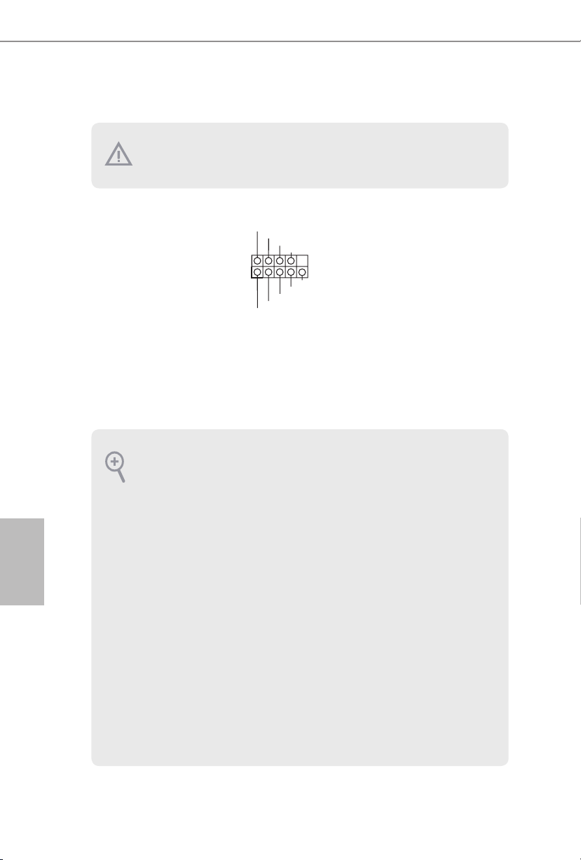
1.4 Conectores y cabezales incorporados
Los cabezales y conectores incorporados NO son puentes. NO coloque tapas de puente sobre estos cabezales y conectores. Si coloca tapas de puente sobre los cabezales y conectores
dañará de forma permanente la placa base.
Español
Cabezal del panel del
sistema
(PANEL1 de 9 pines)
(consulte la pág.1, N.º 13)
PWRBTN (Interruptor de alimentación):
Conéctelo al interruptor de alimentación del panel frontal del chasis. Deberá congurar
la forma en la que su sistema se apagará mediante el interruptor de alimentación.
RESET (Interruptor de reseteo):
Conéctelo al interruptor de reseteo del panel frontal del chasis. Pulse el interruptor de
reseteo para resetear el ordenador si éste está bloqueado y no se puede reiniciar de forma
normal.
PLED (Indicador LED de la alimentación del sistema):
Conéctelo al indicador de estado de la alimentación del panel frontal del chasis. El indicador LED permanece encendido cuando el sistema está funcionando. El indicador LED
parpadea cuando el sistema se encuentra en estado de suspensión S1/S3. El indicador
LED se apaga cuando el sistema se encuentra en estado de suspensión S4 o está apagado
(S5).
HDLED (Indicador LED de actividad en el disco duro):
Conéctelo al indicador LED de actividad en el disco duro del panel frontal del chasis. El
indicador LED permanece encendido cuando el disco duro está leyendo o escribiendo
datos.
El diseño del panel frontal puede ser diferente dependiendo del chasis. Un módulo de
panel frontal consta principalmente de: interruptor de alimentación, interruptor de
reseteo, indicador LED de alimentación, indicador LED de actividad en el disco duro,
altavoz, etc. Cuando conecte su módulo del panel frontal del chasis a este cabezal, asegúrese de que las asignaciones de los cables y los pines coinciden correctamente.
1
PLE D+
PLE D-
HDL ED-
HDL ED+
PWR BTN#
GND
RES ET#
GND
GND
Conecte el interruptor de
alimentación, restablezca el
interruptor y el indicador
del estado del sistema del
chasis a los valores de este
cabezal, según los valores
asignados a los pines como
se indica a continuación.
Cerciórese de cuáles son
los pines positivos y los
negativos antes de conectar
los cables.
54
Page 57

E3V5 WS
PLE D-
IntA _P_ D+
LED de alimentación y
base de conexiones para la
altavoz
(SPK_PLED1 de 7
contactos)
(consulte la pág.1, N.º 11)
Conectores Serie ATA3
(SATA3_0:
consulte la pág.1, N.º 12)
(SATA3_1:
consulte la pág.1, N.º 14)
(SATA3_2:
consulte la pág.1, N.º 9)
(SATA3_3:
consulte la pág.1, N.º 15)
(SATA3_4:
consulte la pág.1, N.º 17)
(SATA3_5:
consulte la pág.1, N.º 16)
Cabezales USB 2.0
(USB2_3 de 9 pines)
(consulte la pág.1, N.º 18)
(USB4_5 de 9 pines)
(consulte la pág.1, N.º 19)
1
USB _PWR
1
USB _PWR
DUM MY
DUM MY
+5V
PLE D+
SATA3_2SATA3_4
SATA3_3SATA3_5
P-
P+
P+
P-
SPE AKER
PLE D+
GND
DUM MY
GND
SATA3_0
SATA3_1
Conecte el LED de
alimentación del chasis y
el altavoz del chasis a esta
base de conexiones.
Estos seis conectores
SATA3 son compatibles
con cables de datos SATA
para dispositivos de
almacenamiento interno
con una velocidad de
transferencia de datos de
hasta 6,0 Gb/s.
Hay dos bases de
conexiones en esta placa
base. Cada cabezal USB 2.0
admite dos puertos.
Español
Cabezal USB 3.0
(USB3_4_5 de 19 pines)
(consulte la pág.1, N.º 6)
1
IntA _P_ D-
IntA _P_ D+
ID
GND
IntA _P_ SSTX +
IntA _P_ SSTX +
GND
IntA _P_ D-
IntA _P_ SSTX -
GND
IntA _P_ SSRX +
GND
IntA _P_ SSTX -
IntA _P_ SSR X-
Vbus
Vbus
IntA _P_ SSR X-
IntA _P_ SSRX +
Además de cuatro puertos
USB 3.0 en el panel I/O,
esta placa base contiene un
cabezal. Cada cabezal USB
3.0 admite dos puertos.
55
Page 58

Cabezal de audio del panel
GND
4 3 2 1
frontal
(HD_AUDIO1 de 9 pines)
(consulte la pág.1, N.º 21)
1. El Audio de Alta Denición (HDA, en inglés) es compatible con el método de sensor de
conectores, sin embargo, el cable del panel del chasis deberá ser compatible con HDA
para que pueda funcionar correctamente. Siga las instrucciones que se indican en
nuestro manual y en el manual del chasis para instalar su sistema.
2. Si utiliza un panel de audio AC’97, colóquelo en el cabezal de audio del panel frontal
siguiendo los pasos que se describen a continuación:
A. Conecte Mic_IN (MIC) a MIC2_L.
B. Conecte Audio_R (RIN) a OUT2_R y Audio_L (LIN) a OUT2_L.
C. Conecte Ground (Conexión a tierra) (GND) a Ground (GND).
D. MIC_RET y OUT_RET se utilizan únicamente con el panel de audio HD. No es
necesario que los conecte en el panel de audio AC’97.
E. Para activar el micrófono frontal, vaya a la cha “micrófono frontal” (FrontMic) en
el panel de control de Realtek y ajuste el “Volumen de grabación” (Recording Volume).
1
GND
PRE SENCE #
MIC 2_R
MIC 2_L
MIC _RET
J_S ENSE
OUT 2_R
OUT _RET
OUT 2_L
Este cabezal se utiliza para
conectar dispositivos de
audio al panel de audio
frontal.
Español
56
Conectores para el
ventilador del chasis
(CHA_FAN1 de 4 pines)
(consulte la pág.1, N.º 7)
(CHA_FAN2 de 4 pines)
(consulte la pág.1, N.º 10)
Conectores del ventilador
de la CPU
(CPU_FAN1 de 4 pines)
(consulte la pág.1, N.º 2)
Conector de alimentación
ATX
(ATXPWR1 de 24 pines)
(consulte la pág.1, N.º 5)
FAN _VO LTA GE
CHA _FA N_S PEE D
FAN _SP EED _CO NTR OL
GND
FAN _VOLT AGE
CPU _F
AN_ SPEED
FAN_ SPEED _CONT ROL
24
12
1
13
Conecte los cables del
ventilador a los conectores
del ventilador y haga
coincidir el cable negro
con el pin de conexión a
tierra.
Esta placa base contiene
un conector de ventilador
(ventilador silencioso) de
CPU de 4 pines. Si tiene
pensando conectar un
ventilador de CPU de 3
pines, conéctelo al Pin 1-3.
Esta placa base contiene
un conector de
alimentación ATX de 24
pines. Para utilizar una
toma de alimentación ATX
de 20 pines, conéctela en
los Pines del 1 al 13.
Page 59
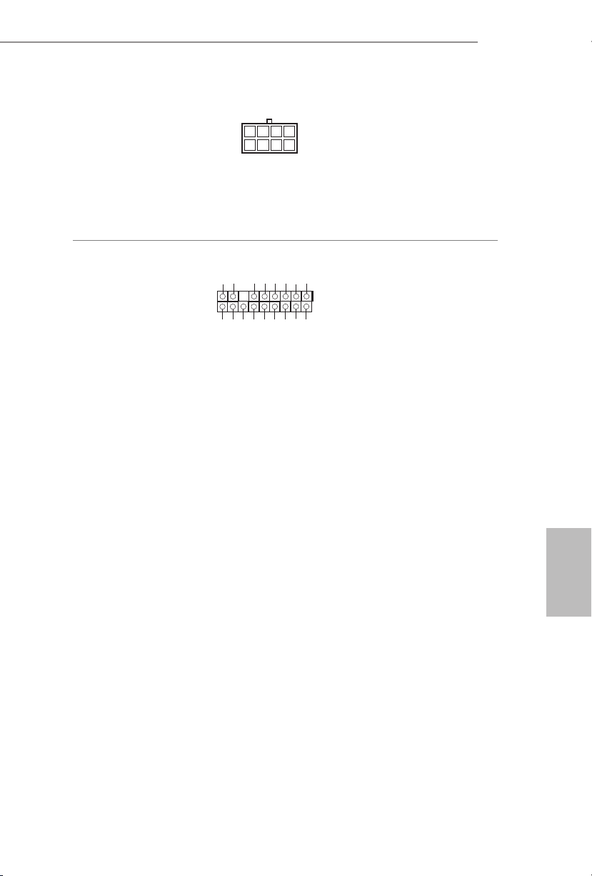
E3V5 WS
5
1
8
Conector de alimentación
ATX de 12V
(ATX12V1 de 8 pines)
(consulte la pág.1, N.º 1)
Cabezal TPM
(TPMS1 de 17 pines)
(consulte la pág.1, N.º 20)
Esta placa base contiene
un conector de alimentación ATX de 12V y 8
pines. Para utilizar una
toma de alimentación ATX
de 4 pines, conéctela en los
Pines del 1 al 5.
Este conector es compatible con el
GN D
LAD 0
+3 V
+3V S B
D
GN
GN D
LAD 1
SER IRQ #
S_P WRD WN #
PC ICL K
LAD 3
PC IRS T #
FRA M E
sistema Módulo de Plataforma Se-
1
gura (TPM, en inglés), que puede
almacenar de forma segura claves,
GN D
LAD 2
certicados digitales, contraseñas
y datos. Un sistema TPM también
SMB _CL K_MA IN
SMB _DA TA_M AIN
ayuda a aumentar la seguridad
en la red, protege las identidades
digitales y garantiza la integridad
de la plataforma.
Español
57
Page 60

Русский
1 Введение
Благодарим вас за приобретение надежной системной платы ASRock E3V5 WS,
выпускаемой под постоянным жестким контролем качества компании ASRock.
Эта материнская плата обеспечивает великолепную производительность
и характеризуется прочной конструкцией в соответствии с требованиями
компании ASRock в отношении качества и долговечности.
По причине обновления спецификации на материнскую платформу и
программного обеспечения BIOS содержимое настоящей документации может
быть изменено без предварительного уведомления. При изменении содержимого
настоящего документа его обновленная версия будет доступна на веб-сайте
ASRock без предварительного уведомления. При необходимости технической
поддержки, связанной с материнской платой, посетите веб-сайт и найдите
на нем информацию о модели используемой вами материнской платы. На вебсайте ASRock также можно найти самый последний перечень поддерживаемых
VGA-карт и ЦП. Веб-сайт ASRock http://www.asrock.com.
1.1 Комплект поставки
•Системная плата ASRock E3V5 WS (форм-фактор ATX)
•Краткое руководство по установке платы ASRock E3V5 WS
•Компакт-диск с ПО для платы ASRock E3V5 WS
•2 х кабеля передачи данных Serial ATA (SATA) (приобретаются отдельно)
•1 х экран панели с портами ввода-вывода
58
Page 61

1.2 Спецификация
E3V5 WS
Платформа
Процессор
Чипсет
Память
Слот
расширения
•Форм-фактор ATX
•Схема на основе твердотельных конденсаторов
•Поддержка процессоров Intel® Xeon® E3-1200 v5 и
процессоров 6-го поколения Intel® CoreTM i7/i5/i3/
Pentium®/Celeron® (Socket 1151)
•Система питания 5
•Поддержка технологии Intel® Turbo Boost 2.0
•Intel® C232
•Двухканальная память DDR4
•4 x гнезда DDR4 DIMM
•Поддержка модулей небуферизованной памяти DDR4
2133 без ECC
•Поддерживаются модули памяти UDIMM с ECC
* ECC поддерживается только с процессором Intel® E3/
CoreTM i3/Pentium®/Celeron®. С процессором Intel® CoreTM
i7/i5, это лань не поддерживает ECC.
•Максимальный объем системной памяти: 64 Гб
•Поддержка Intel® Extreme Memory Prole (XMP) 2.0
•Гнезда DIMM с золочеными контактами 15мк
•2 x Слоты PCI Express 3.0 x16 (PCIE2:режим x16;
PCIE4:режим x4)*
* Поддерживаются в качестве загрузочных SSD-диски
типа NVMe.
•3 x PCI Express 3.0 x1 разъем (Flexible PCIe)
•Поддержка AMD Quad CrossFireX
•15μ Золоченые контакты разъема VGA PCIe (PCIE2)
TM
и CrossFireXTM
Русский
Аудио
LAN
•7.1-канальный звук высокой четкости HD Audio с
защитой данных (аудиокодек Realtek ALC892)
*Для настройки 7.1-канального звук высокой четкости
HD Audio используйте переднюю аудиопанель HD
и активируйте функцию многоканального звука в
аудиодрайвере.
•Поддержка Premium Blu-ray Audio
•Защита от перенапряжения (ASRock Full Spike
Protection)
•Конденсаторы для аудиосистем ELNA
•Gigabit LAN 10/100/1000 Мб/с
•Giga PHY Intel® I219LM
59
Page 62

•Поддержка Wake-On-LAN
•Молниезащита и защита электростатического
напряжения (ASRock Full Spike Protection)
•Поддержка Energy Ecient Ethernet 802.3az
•Поддержка PXE
Русский
Порты вводавывода
на задней
панели
Запоминающие
устройства
Разъемы
•1 x порт PS/2 для мыши
•1 x PS/2 для клавиатуры
•2 x Порты USB 2.0 с защитой от электростатического
напряжения (ASRock Full Spike Protection)
•4 x Порты USB 3.0 с защитой от электростатического
напряжения (ASRock Full Spike Protection)
•1 x RJ-45 для ЛВС с СИД (СИД ACT/LINK и СИД
SPEED)
•Разъемы HD Audio: Линейный вход / передние
динамики / микрофон
•6 x разъемы SATA3 6,0 Гб/с, поддержка RAID (RAID
0, RAID 1, RAID 5, RAID 10, Intel RSTe), NCQ, AHCI и
«горячая» замена
•1 x Колодка ТРМ
•1 x колодка светодиодного индикатора питания и
динамика корпуса
•1 x Разъем для вентилятора охлаждения процессора
(4-контактный) ("Умный" регулятор скорости
вентилятора)
•2 x Разъемы для вентилятора корпуса (4-контактный)
("Умный" регулятор скорости вентилятора)
•1 х разъем питания АТХ (24-контактный)
•1 x 8-контактный разъем питания 12 В
•1 x аудиоразъем на передней панели
•2 x Колодки USB 2.0 (до 4 портов USB 2.0) с защитой
от электростатического напряжения (ASRock Full
Spike Protection)
•1 x Колодка USB 3.0 (до 2 портов USB 3.0) с защитой от
электростатического напряжения (ASRock Full Spike
Protection)
60
Параметры
BIOS
•AMI UEFI Legal BIOS с поддержкой многоязычного
графического интерфейса
Page 63

•Совместимость с функцией энергопотребления в
стандарте ACPI 5.0
•Поддерживается SMBIOS 2.7.
•Регулировка напряжений ЦП, DRAM, VPPM, PCH
1,0V, VCCIO, VCCSA
E3V5 WS
Контроль
оборудования
ОС
Сертификация
•Датчик температуры процессора/корпуса
•Тахометр вентилятора процессора/корпуса
•Бесшумный вентилятор охлаждения процессора/
корпуса (с автоматической регулировкой скорости
вращения в зависимости от температуры нагрева
процессора)
•Управление скоростью вращения вентилятора
охлаждения процессора/корпуса
•Контроль напряжения: +12 В, +5 В, +3,3 В, ЦП Vcore
•Microso® Windows® 10 64-разрядная /
8.1 64-разрядная/ 7 32-разрядная/ 7 64-разрядная /
Server 2012 R2 64-разрядная / Server 2012 64-разрядная
/ Server 2008 R2 64-разрядная
* Для установки ОС Windows® 7 потребуется измененный
установочный диск с драйверами xHCI, упакованными в
файл ISO. Более подробные инструкции представлены на
стр. 125.
* Подробные сведения об обновлении драйвера
Windows® 10 представлены на веб-сайте ASRock:
http://www.asrock.com
•FCC, CE, WHQL
•Совместимость с ErP/EuP (необходим блок питания,
соответствующий стандарту ErP/EuP)
Русский
* Для получения дополнительной информации об изделии посетите наш веб-сайт:
http://www.asrock.com
Следует учитывать, что разгон процессора, включая изменение настроек
BIOS, применение технологии Untied Overclocking Technology и использование
инструментов разгона независимых производителей, сопряжен с определенным
риском. Разгон процессора может повлиять на стабильность системы или
даже привести к повреждению ее компонентов и устройств. Вы выполняете
разгон процессора на ваш собственный риск и за свой счет. Мы не несем
ответственность за возможный ущерб, вызванный разгоном процессора.
61
Page 64
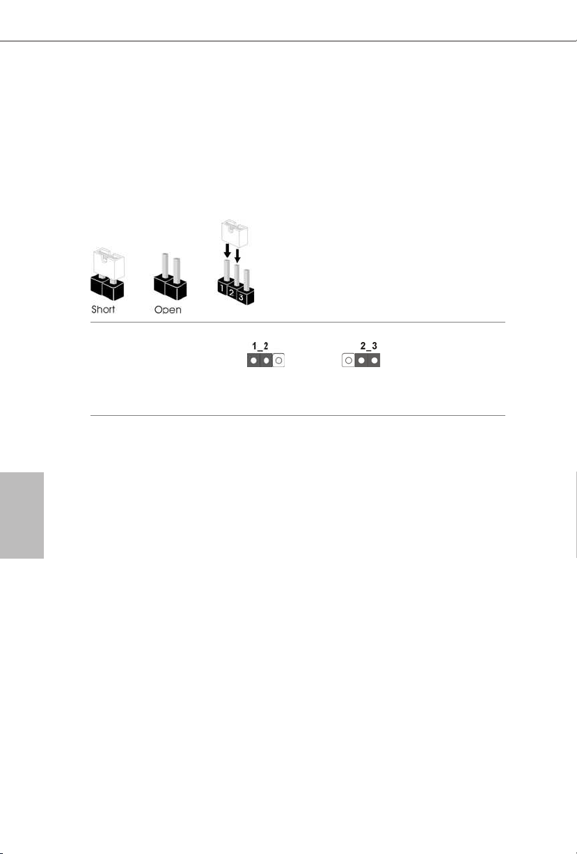
Русский
1.3 Установка перемычек
Установка перемычек показана на рисунке. При установке колпачковой
перемычки на контакты перемычка «замкнута». Если колпачковая перемычка
на контакты не установлена, перемычка «разомкнута». На рисунке показана
3-контактная перемычка с замкнутыми контактами 1 и 2 при установке на них
колпачковой перемычки.
Перемычка сброса
настроек CMOS
(CLRMOS1)
(См. стр. 1, № 8)
CLRMOS1 используется для удаления данных CMOS. Чтобы сбросить и
обнулить параметры системы на настройки по умолчанию, выключите
компьютер и извлеките отключите кабель питания от источника питания.
Выждите 15 секунд и перемычкой замкните контакты 2 и 3 на CLRMOS1 на
5 секунд. Не сбрасывайте настройки CMOS сразу после обновления BIOS.
При необходимости сбросить настройки CMOS сразу после обновления BIOS
сначала перезагрузите систему, а затем выключите компьютер перед сбросом
настроек CMOS. Учтите, что пароль, дата, время и профиль пользователя по
умолчанию сбрасываются только в том случае, если извлечь батарею CMOS.
Сброс настроек CMOSпо умолчанию
62
Page 65

E3V5 WS
1.4 Колодки и разъемы, расположенные на материнской
плате
Расположенные на материнской плате колодки и разъемы перемычками
НЕ являются. НЕ устанавливайте на эти колодки и разъемы колпачковые
перемычки. Установка колпачковых перемычек на эти колодки и разъемы может
вызвать неустранимое повреждение материнской платы.
Колодка системной
панели
(9-контактная, PANEL1)
(См. стр. 1, № 13)
PWRBTN (кнопка питания):
Подключение кнопки питания, расположенной на передней панели корпуса.
Можно настроить порядок выключения системы с использованием кнопки
питания.
RESET (кнопка перезагрузки):
Подключение кнопки перезагрузки системы, расположенной на передней панели
корпуса. Нажмите кнопку перезагрузки, чтобы перезапустить компьютер, если
он завис и нормальный запуск невозможен.
PLED (светодиодный индикатор питания системы):
Подключение индикатора состояния, расположенного на передней панели
корпуса. Светодиодный индикатор горит, когда система работает. Когда
система находится в режиме ожидания S1/S3, светодиод мигает. Когда система
находится в режиме ожидания S4 или выключена (S5), светодиод не горит.
HDLED (светодиодный индикатор работы жесткого диска):
Подключение светодиодного индикатора работы жесткого диска,
расположенного на передней панели. Светодиодный индикатор горит, когда
жесткий диск выполняет считывание или запись данных.
Передняя панель может быть разной на разных корпусах. В основном передняя
панель включает в себя кнопку питания, кнопку перезагрузки, светодиодный
индикатор питания, светодиодный индикатор работы жесткого диска,
динамик и т. д. При подключении передней панели к этой колодке правильно
подключайте провода к контактам.
1
PLE D+
PLE D-
HDL ED-
HDL ED+
PWR BTN#
GND
RES ET#
GND
GND
Подключите
расположенные на
корпусе выключатель
питания, кнопку
перезагрузки и индикатор
состояния системы к этой
колодке в соответствии
с распределением
контактов,
приведенным ниже.
Перед подключением
кабелей определите
положительный и
отрицательный контакты.
Русский
63
Page 66
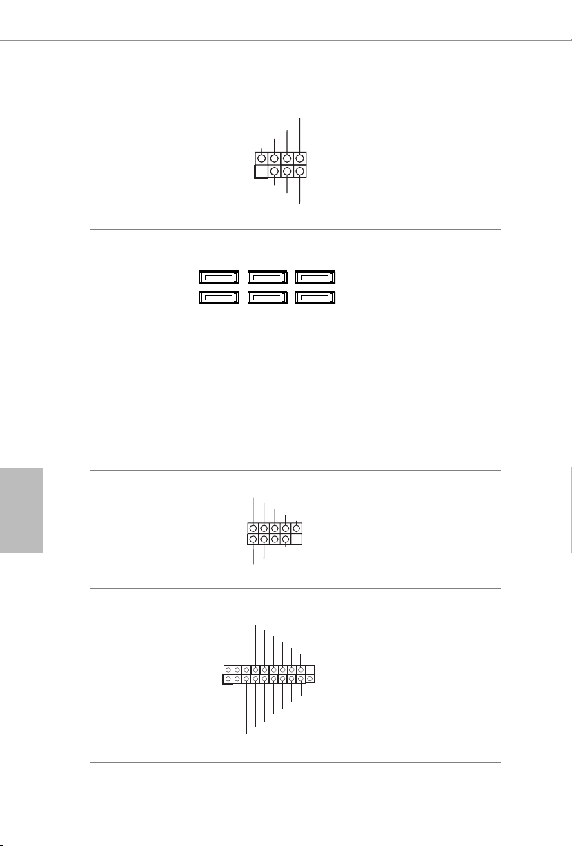
Колодка светодиодного
PLE D-
SPE AKER
IntA _P_ D+
индикатора питания и
динамика корпуса
(7-контактная,
SPK_PLED1)
(См. стр. 1, № 11)
DUM MY
+5V
1
PLE D+
DUM MY
PLE D+
Предназначена
для подключения
светодиодного
индикатора питания и
динамика корпуса.
Русский
Разъемы Serial ATA3
(SATA3_0:
См. стр. 1, № 12)
(SATA3_1:
См. стр. 1, № 14)
(SATA3_2:
см. стр.1, № 9)
(SATA3_3:
См. стр. 1, № 15)
(SATA3_4:
См. стр. 1, № 17)
(SATA3_5:
см. стр.1, № 16)
Колодки USB 2.0
(9-контактная, USB2_3)
(См. стр. 1, № 18)
(9-контактная, USB4_5)
(См. стр. 1, № 19)
Колодка USB 3.0
(19-контактная,
USB3_4_5)
(См. стр. 1, № 6)
1
IntA _P_ D-
IntA _P_ D+
ID
SATA3_2SATA3_4
SATA3_3SATA3_5
USB _PWR
1
USB _PWR
GND
IntA _P_ SSTX +
GND
IntA _P_ D-
P-
P+
GND
GND
P+
P-
IntA _P_ SSTX -
GND
IntA _P_ SSRX +
GND
IntA _P_ SSTX -
IntA _P_ SSTX +
SATA3_0
SATA3_1
DUM MY
IntA _P_ SSR X-
Vbus
Vbus
IntA _P_ SSR X-
IntA _P_ SSRX +
Эти шесть
разъемов SATA3
предназначены для
подключения кабелей
SATA внутренних
запоминающих
устройств для передачи
данных со скоростью до
6,0 Гб/с.
На системной плате
размещены две колодки.
Каждая колодка USB 2.0
может поддерживать два
порта.
Кроме четыре портов
USB 3.0 на панели вводавывода на системной
плате также имеется
одна колодка. Каждая
колодка USB 3.0 может
поддерживать два порта.
64
Page 67
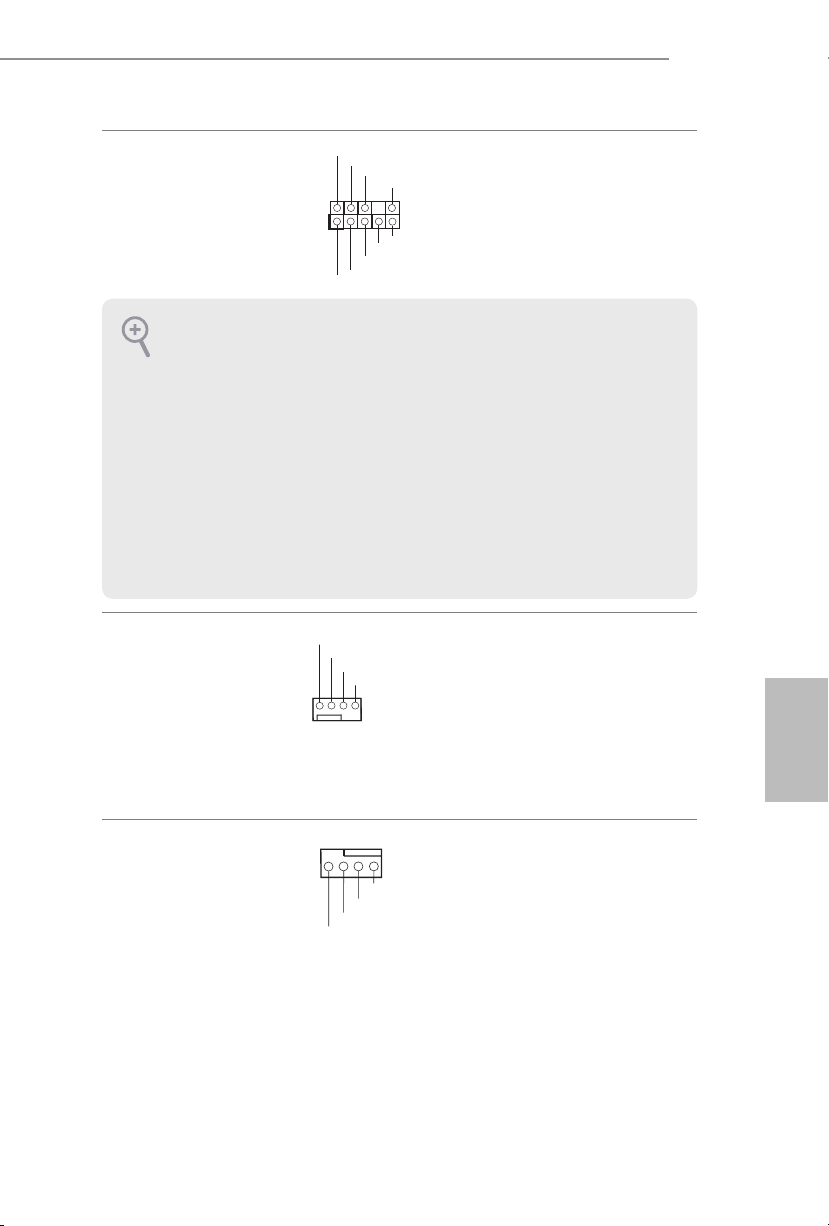
E3V5 WS
4 3 2 1
Аудиоколодка передней
панели
(9-контактная, HD_
AUDIO1)
(См. стр. 1, № 21)
1. Аудиосистема высокого разрешения поддерживает функцию распознавания
разъема, но для е правильной работы необходимо, чтобы провод панели
корпуса поддерживал передачу сигналов HDA. Инструкции по установке
системы см. в этом руководстве и руководстве на корпус.
2. При использовании аудиопанели AC’97 подключите ее к аудиоколодке передней
панели, как указано далее:
A. Подключите Mic_IN (MIC) к MIC2_L.
B. Подключите Audio_R (RIN) к OUT2_R, Audio_L (LIN) к OUT2_L.
C. Подключите провод заземления (GND) к контакту заземления (GND).
D. Контакты MIC_RET и OUT_RET используются только для аудиопанели
высокого разрешения. При использовании аудиопанели AC’97 их подключать не
нужно.
E. Чтобы активировать передний микрофон, перейдите на вкладку FrontMic
панели управления Realtek и отрегулируйте параметр Recording Volume
(Громкость записи).
Разъемы вентиляторов
корпуса
(4-контактный,
CHA_FAN1)
(См. стр. 1, № 7)
(4-контактный,
CHA_FAN2)
(См. стр. 1, № 10)
1
GND
FAN _VO LTA GE
GND
MIC 2_L
CHA _FA N_S PEE D
PRE SENCE #
MIC _RET
OUT _RET
OUT 2_L
J_S ENSE
OUT 2_R
MIC 2_R
FAN _SP EED _CO NTR OL
Эта колодка
предназначена
для подключения
аудиоустройств к
передней аудиопанели.
Предназначены для
подключения кабелей
разъемов вентиляторов
и подключения черного
провода к заземлению.
Русский
Разъемы вентиляторов
ЦП
(4-контактный, CPU_
FAN1)
(См. стр. 1, № 2)
GND
FAN _VOLT AGE
CPU _F
AN_ SPEED
FAN_ SPEED _CONT ROL
Эта материнская
плата снабжена
4-контактным разъемом
для малошумящего
вентилятора ЦП. Если вы
собираетесь подключить
3-контактный
вентилятор охлаждения
процессора, подключайте
его к контактам 1-3.
65
Page 68
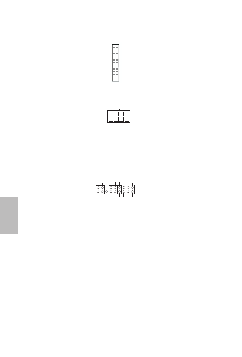
Разъем питания АТХ
1
(24-контактный,
ATXPWR1)
(См. стр. 1, № 5)
24
12
Эта материнская плата
снабжена 24-контактным
разъемом питания АТХ.
Чтобы использовать
20-контактный
1
13
разъем питания ATX,
подключите его вдоль
контакта 1 и контакта 13.
Русский
Разъем питания
АТХ 12 В
(8-контактный,
ATX12V1)
(См. стр. 1, № 1)
Колодка ТРМ
(17-контактная, TPMS1)
(См. стр. 1, № 20)
Эта материнская плата
8
5
снабжена 8-контактным
разъемом питания АТХ
12 В. Чтобы использовать
4-контактный
разъем питания ATX,
подключите его вдоль
контакта 1 и контакта 5.
Этот разъем обеспечивает
GN D
LAD 0
+3 V
+3V S B
D
GN
GN D
LAD 1
SER IRQ #
S_P WRD WN #
PC ICL K
LAD 3
PC IRS T #
FRA M E
LAD 2
поддержку системы Trusted
1
Platform Module (TPM), которая
способна обеспечить надежное
GN D
хранение ключей, цифровых
сертификатов, паролей и
SMB _CL K_MA IN
SMB _DA TA_M AIN
данных. Система ТРМ также
повышает уровень сетевой
безопасности, защищает
цифровые идентификаторы
и обеспечивает целостность
платформы.
66
Page 69
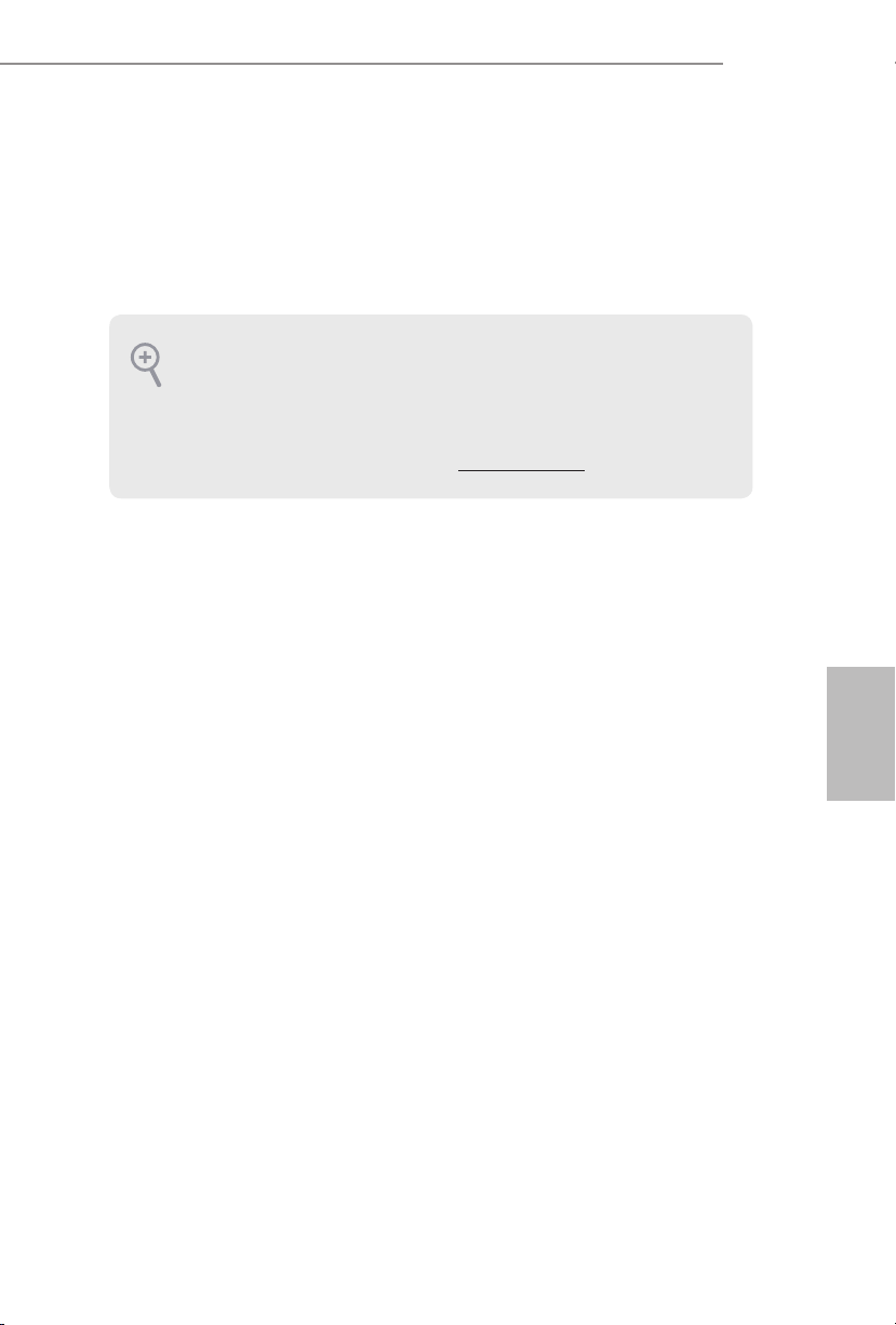
1 Introdução
Obrigado por adquirir a placa mãe ASRock E3V5 WS, uma conável placa mãe
ASRock produzida sob rigoroso controle de qualidade consistente. Esta placa principal
oferece um excelente desempenho com um design robusto em conformidade com o
compromisso da ASRock em fabricar produtos de qualidade e resistentes.
Como as especicações da placa-mãe e do soware do BIOS podem ser atualizadas, o
conteúdo desta documentação estará sujeito a alterações sem aviso prévio. Caso ocorram modicações a esta documentação, a versão atualizada estará disponível no site
da ASRock sem aviso prévio. Se precisar de assistência técnica relacionada a esta placa
principal, visite o nosso site para obter informações especícas sobre o modelo que estiver
utilizando. Você também poderá encontrar a lista de placas VGA e CPU mais recentes
suportadas no site da ASRock. Site da ASRock http://www.asrock.com.
1.1 Conteúdo da embalagem
•Placa Mãe ASRock E3V5 WS (Fator de Forma ATX)
•Guia de Instalação Rápida da ASRock E3V5 WS
•CD de Suporte da ASRock E3V5 WS
•2 x Cabos de dados Serial ATA (SATA) (Opcional)
•1 x Painel de E/S
E3V5 WS
67
Português
Page 70

1.2 Especicações
Português
Plataforma
CPU
Chipset
Memória
Slot de
expansão
•Formato ATX
•Design de condensador sólido
•Supports Processadores Intel® Xeon® E3-1200 v5 e
Processadores Intel® 6ª Geração CoreTM i7/i5/i3/Pentium®/
Celeron® (Soquete 1151)
•Design com 5 fases de alimentação
•Suporta a tecnologia Intel® Turbo Boost 2.0
•Intel® C232
•Tecnologia de memória DDR4 de dois canais
•4 x Slots DIMM DDR4
•Suporta memória DDR4 2133, não ECC, sem memória
intermédia
•Suporta módulos de memória ECC UDIMM
* ECC é suportado apenas com CPU Intel® E3/CoreTM i3/Pentium®/
Celeron®. Com CPU Intel® CoreTM i7/i5, o ECC não irá funcionar.
•Capacidade máxima da memória do sistema: 64GB
•Suporta Extreme Memory Prole (XMP) 2.0 da Intel®
•Contato em Ouro 15μ nos slots DIMM
•2 x Slots PCI Express 3.0 x16 (PCIE2:modo x16;
PCIE4:modo x4)*
* Suporta NVMe SSD nos discos de inicialização
•3 x Slots PCI Express 3.0 x1 (Flexible PCIe)
•Suporta AMD Quad CrossFireX
•Contato em Ouro 15μ no Slot PCIe VGA (PCIE2)
TM
e CrossFireXTM
68
Áudio
•Áudio HD de 7.1 canais com proteção de conteúdo (Codec de
áudio Realtek ALC892)
*Para congurar Áudio 7.1 CH HD, é necessário usar um módulo
de áudio de painel frontal HD e habilitar o recurso de áudio multicanal pelo driver de áudio.
•Suporte áudio Blu-ray superior
•Suporta proteção contra sobretensão (Proteção Total Contra
Picos ASRock)
•Fones de Áudio ELNA
Page 71

E3V5 WS
LAN
E/S do
painel
posterior
Armazenamento
Conector
•LAN Gigabit a 10/100/1000 Mb/s
•Giga PHY Intel® I219LM
•Suporta Wake-On-LAN
•Suporta Proteção contra Relâmpago/ESD (Proteção Total
Contra Picos ASRock)
•Suporta Energy Ecient Ethernet 802.3az
•Suporta PXE
•1 x Porta PS/2 para mouse
•1 x Porta PS/2 para Teclado
•2 x Portas USB 2.0 (Suporta Proteção ESD (Proteção Total
Contra Picos ASRock))
•4 x Portas USB 3.0 (Suporta Proteção ESD (Proteção Total
Contra Picos ASRock))
•1 x Porta LAN RJ-45 com LED (LED ACT/LINK e LED DE
VELOCIDADE)
•Fichas de áudio HD: Entrada de Linha / Autofalante Frontal /
Microfone
•6 x Conectores SATA3 6,0 Gb/s, suporte RAID (RAID 0, RAID
1, RAID 5, RAID 10, Intel® RSTe), NCQ, AHCI e Conexão a
Quente
•1 x Plataforma TPM
•1 x LED de alimentação e Cabeçote de Autofalante
•1 x Conector de Ventoinha de CPU (4 pinos) (Controle de
Velocidade de Ventoinha Inteligente)
•2 x Conectores de Ventoinha de Chassi (4 pinos) (Controle de
Velocidade de Ventoinha Inteligente)
•1 x conector alimentação ATX 24 pinos
•1 x Conector de energia 8-pinos 12V
•1 x conector de áudio do painel frontal
•2 x Plataformas USB 2.0 (Suporta 4 portas USB 2.0) (Suporta
Proteção ESD (Proteção Total Contra Picos ASRock))
•1 x Plataforma USB 3.0 (Suporta 2 portas USB 3.0) (Suporta
Proteção ESD (Proteção Total Contra Picos ASRock))
Português
69
Page 72
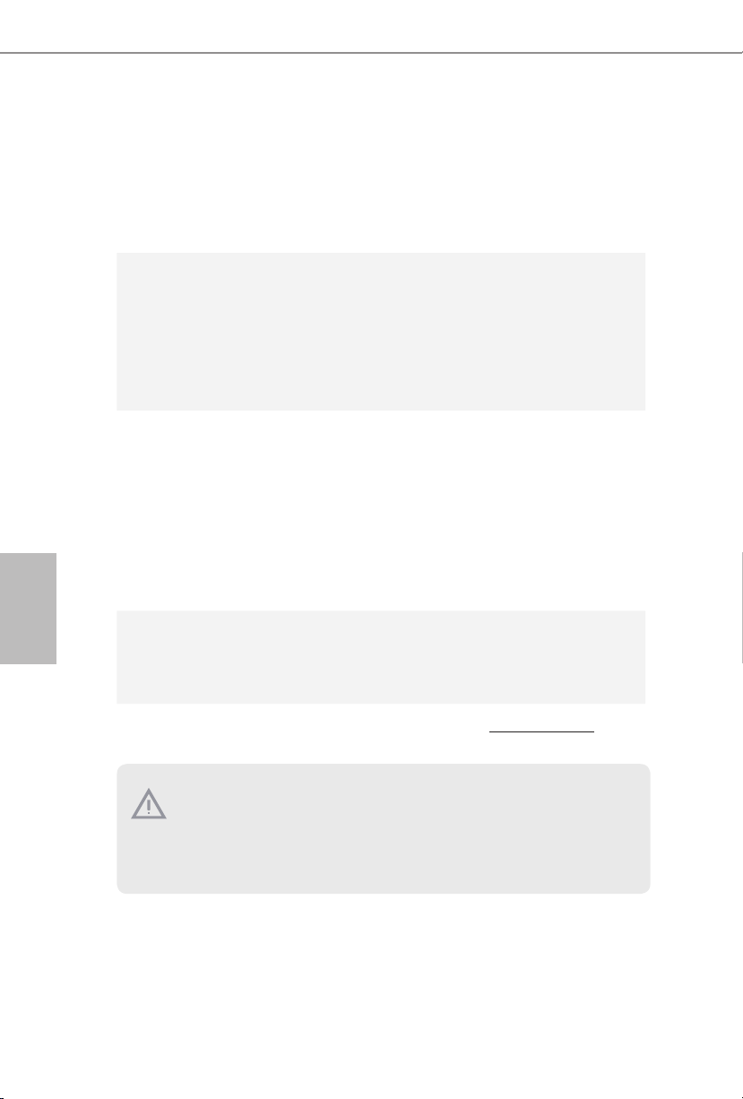
Funções
da BIOS
•AMI Legal UEFI BIOS com suporte multilingue GUI
•ACPI 5.0 compatível com eventos de despertar
•Suporte SMBIOS 2.7
•CPU, DRAM, VPPM, PCH 1,0V, VCCIO, VCCSA Multi ajuste
de tensão
Português
Monitor de
hardware
•Sensor de temperatura da CPU/Gabinete
•Tacômetro da Ventoinha da CPU/Gabinete
•Ventoinha silenciosa da CPU/Gabinete (Auto ajusta veloci-
dade da ventoinha do gabinete pela temperatura da CPU)
•Controle de multi velocidade da Ventoinha da CPU/Gabinete
•Monitoramento da tensão: +12V, +5V, +3,3V, CPU Vcore
SO
•Microso® Windows® 10 64-bit / 8.1 64-bit / 7 32-bit / 7 64-bit
/ Server 2012 R2 64-bit / Server 2012 64-bit / Server 2008 R2
64-bit
*Para instalar o SO Windows® 7, um disco de instalação
modicado com condutores xHCI no arquivo ISO é necessário.
Favor consultar a página 125 para mais instruções detalhadas.
* Para o driver atualizado do Windows® 10, por favor, visite o
website da ASRock para mais detalhes: http://www.asrock.com
Certicações
•FCC, CE, WHQL
•Preparada para ErP/EuP (é necessária uma fonte de alimen-
tação preparada para ErP/EuP)
* Para obter informações detalhadas sobre o produto, por favor, visite o nosso site: http://www.asrock.com
Por favor, observe que existe um certo risco envolvendo overclocking, incluindo o ajuste
das denições na BIOS, a aplicação de tecnologia Untied Overclocking ou a utilização
de ferramentas de overclocking de terceiros. O overclocking poderá afetar a estabilidade
do sistema ou mesmo causar danos nos componentes e dispositivos do seu sistema. Ele
deve ser realizado por sua conta e risco. Não nos responsabilizamos por possíveis danos
causados pelo overclocking.
70
Page 73

1.3 Conguração dos jumpers
A imagem abaixo mostra como os jumpers são congurados. Quando a tampa do
jumper é colocada nos pinos, o jumper é "Curto". Se não for colocada uma tampa de
jumper nos pinos, o jumper é "Aberto". A imagem mostra um jumper de 3 pinos cujos
pino1 e pino2 estão "Curtos" quando a tampa do jumper é colocada nestes 2 pinos.
Apagar o Jumper CMOS
(CLRMOS1)
(ver p.1, N.º 8)
CLRMOS1 permite que você limpe os dados do CMOS. Para apagar e reinicializar
os parâmetros do sistema nos valores predenidos, desligue o computador e
desplugue a tomada da alimentação. Depois de aguardar 15 segundos, use uma capa
de jumper para fazer curto do pino 2 e do pino3 no CLRMOS1 por 5 segundos. No
entanto, não apague o CMOS logo após ter realizado a atualização da BIOS. Se você
precisar apagar o CMOS logo após ter terminado uma atualização da BIOS, deverá
primeiro iniciar o sistema e voltar a encerrá-lo antes de apagar o CMOS. Por favor,
observe que a senha, data, hora e perl padrão do usuário serão apagados só se a
bateria CMOS for removida.
Apagar CMOSPadrão
E3V5 WS
Português
71
Page 74

1.4 Suportes e conectores onboard
Os conectores e suportes onboard NÃO são jumpers. NÃO coloque tampas de jumpers
sobre estes terminais e conectores Colocar tampas de jumpers sobre os terminais e conectores irá causar danos permanentes à placa-mãe.
Português
Suporte do painel de
sistema
(PAINEL1 de 9 pinos)
(ver p.1, N.º 13)
PWRBTN (Botão de alimentação):
Conecte o botão de alimentação no painel frontal do chassi. Você pode congurar a
forma para desligar o seu sistema através do botão de alimentação.
RESET (Botão de reinicialização):
Conecte o botão de reinicialização no painel frontal do chassi. Pressione o botão de
reinicialização para reiniciar o computador, se ele congela e falha ao realizar um reinício
normal.
PLED (LED de alimentação do sistema):
Conecte o indicador do estado da alimentação no painel frontal do chassi. O LED cará
aceso quando o sistema estiver em funcionamento. O LED cará piscando quando o
sistema estiver nos estados de suspensão S1/S3. O LED cará desligado quando o sistema
estiver no estado de suspensão S4 ou desligado (S5).
HDLED (LED de atividade do disco rígido):
Conecte o LED de atividade do disco rígido no painel frontal do chassi. O LED cará
aceso quando o disco rígido estiver lendo ou registrando dados.
O design do painel frontal poderá variar dependendo do chassi. Um módulo de painel
frontal consiste principalmente em um botão de alimentação, um botão de reinicialização, um LED de alimentação, um LED de atividade do disco rígido, um alto-falante, etc.
Ao conectar seu módulo de painel frontal do chassi a este conector, certique-se de que os
os e os pinos correspondem de forma correta.
1
PLE D+
PLE D-
HDL ED-
HDL ED+
PWR BTN#
GND
RES ET#
GND
GND
Ligue o botão de
alimentação, o botão
de reinicialização e o
indicador do estado do
sistema no chassi deste
suporte, de acordo com a
descrição abaixo. Observe
os pinos positivos e
negativos antes de conectar
os cabos.
72
Page 75
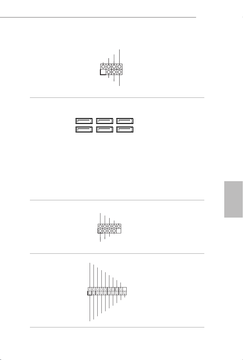
E3V5 WS
PLE D-
IntA _P_ D+
LED de alimentação e
Cabeçote de Autofalante
(SPK_PLED1 de 7 pinos)
(ver p.1, N.º 11)
Conectores série ATA3
(SATA3_0:
ver p.1, N.º 12)
(SATA3_1:
ver p.1, N.º 14)
(SATA3_2:
ver p.1, N.º 9)
(SATA3_3:
ver p.1, N.º 15)
(SATA3_4:
ver p.1, N.º 17)
(SATA3_5:
ver p.1, N.º 16)
Suportes USB 2.0
(USB2_3 de 9 pinos)
(ver p.1, N.º 18)
(USB4_5 de 9 pinos)
(ver p.1, N.º 19)
DUM MY
+5V
1
SATA3_2SATA3_4
SATA3_3SATA3_5
USB _PWR
1
USB _PWR
DUM MY
PLE D+
PLE D+
P-
P+
P-
SPE AKER
SATA3_0
SATA3_1
GND
DUM MY
GND
P+
Conecte o LED de
alimentação do chassi e o
autofalante do chassi a este
cabeçote.
Estes seis conectores
SATA3 suportam
cabos de dados SATA
para dispositivos de
armazenamento interno
com uma taxa de
transferência de dados de
até 6,0 Gb/s.
Há dois cabeçotes nesta
placa-mãe. Cada suporte
USB 2.0 pode suportar
duas portas.
Português
Suporte USB 3.0
(USB3_4_5 de 19 pinos)
(ver p.1, N.º 6)
1
IntA _P_ D-
IntA _P_ D+
ID
GND
IntA _P_ SSTX +
GND
IntA _P_ D-
IntA _P_ SSTX -
GND
IntA _P_ SSRX +
GND
IntA _P_ SSTX -
IntA _P_ SSTX +
IntA _P_ SSR X-
Vbus
Vbus
IntA _P_ SSR X-
IntA _P_ SSRX +
Além de quatro portas
USB 3.0 no painel de E/
S, existe uma plataforma
nesta placa-mãe. Cada
suporte USB 3.0 pode
suportar duas portas.
73
Page 76

Suporte de áudio do painel
4 3 2 1
frontal
(HD_AUDIO1 de 9 pinos)
(ver p.1, N.º 21)
1. O Áudio de alta denição suporta Sensor de Adaptador, mas o o do painel no chassi
deverá suportar HDA para funcionar corretamente. Por favor, siga as instruções no
nosso manual e no manual do chassi para instalar o seu sistema.
2. Se utilizar um painel de áudio AC’97, instale-o no terminal de áudio do painel frontal
de acordo com os passos abaixo:
A. Ligue Mic_IN (MIC) a MIC2_L.
B. Conecte o Audio_R (RIN) a OUT2_R e Audio_L (LIN) a OUT2_L.
C. Conecte a ligação Terra (GND) à Terra (GND).
D. MIC_RET e OUT_RET destinam-se apenas ao painel de áudio HD. Você não
precisa ligá-los ao painel de áudio AC’97.
E. Para ativar o microfone frontal, vá à guia “Microfone Frontal” no painel de controle
Realtek e ajuste o “Volume de gravação”.
1
GND
PRE SENCE #
MIC 2_R
MIC 2_L
MIC _RET
J_S ENSE
OUT 2_R
OUT _RET
OUT 2_L
Este suporte destina-se à
conexão dos dispositivos
de áudio no painel de
áudio frontal.
Português
74
Conectores da Ventoinha
do Chassi
(CHA_FAN1 de 4 pinos)
(ver p.1, N.º 7)
(CHA_FAN2 4 pinos)
(ver p.1, N.º 10)
Conectores do ventilador
da CPU
(CPU_FAN1 de 4 pinos)
(ver p.1, N.º 2)
Conector de alimentação
ATX
(ATXPWR1 de 24 pinos)
(ver p.1, N.º 5)
GND
FAN _VO LTA GE
CHA _FA N_S PEE D
FAN _SP EED _CO NTR OL
GND
FAN _VOLT AGE
CPU _F
AN_ SPEED
FAN_ SPEED _CONT ROL
12 124
Por favor, conecte os
cabos do ventilador aos
conectores do ventilador e
corresponda o o preto no
pino terra.
Esta placa mãe inclui um
conector de ventilador da
CPU (Ventilador silencioso)
de 4 pinos. Se você pretende
conectar um ventilador da
CPU de 3 pinos, por favor,
conecte-o ao Pino 1-3.
Esta placa-mãe inclui um
conector de alimentação
ATX de 24 pinos. Para
utilizar uma fonte de alimentação ATX de 20 pinos,
13
introduza-a no Pino 1 e
Pino 13.
Page 77

E3V5 WS
5
1
8
Conector de alimentação
de 12V ATX
(ATX12V1 de 8 pinos)
(ver p.1, N.º 1)
Suporte TPM
(TPMS1 de 17 pinos)
(ver p.1, N.º 20)
Esta placa-mãe inclui um
conector de alimentação
de 12V ATX de 8 pinos.
Para utilizar uma fonte
de alimentação ATX de 4
pinos, introduza-a no Pino
1 e Pino 5.
Este conector suporta um sistema
GN D
LAD 0
LAD 3
+3 V
PC IRS T #
+3V S B
D
GN
SER IRQ #
S_P WRD WN #
FRA M E
GN D
LAD 1
LAD 2
SMB _CL K_MA IN
SMB _DA TA_M AIN
com Módulo de Plataforma Con-
PC ICL K
1
ável (TPM), que pode armazenar
com segurança chaves, certica-
GN D
dos digitais, senhas e dados. Um
sistema TPM também ajuda a
melhorar a segurança de rede, a
proteger identidades digitais e a
garantir a integridade da plataforma.
Português
75
Page 78

1 Giriş
ASRock'ın zorlu kalite kontrol süreçlerinden geçmiş olan ASRock E3V5 WS
anakartını satın aldığınız için teşekkür ederiz. Sağlam tasarımı ile ASRock'ın kalite ve
dayanıklılık taahhüdüne uygun şekilde mükemmel performans sağlar.
Anakart özellikleri ve BIOS yazılımı güncellenebileceğinden, bu dokümantasyonun
içeriği herhangi bir bildirimde bulunulmaksızın değiştirilebilir. Bu dokümantasyon
üzerinde herhangi bir değişiklik yapılması halinde, güncellenmiş sürüm, herhangi bir
bildirim yapılmaksızın ASRock'ın web sitesinde yer alacaktır.. Bu anakart ile ilgili olarak
teknik destek almak istiyorsanız, lütfen kullandığınız model hakkında özel bilgiler için
web sitemizi ziyaret edin. En güncel VGA kartları ve CPU destek listelerini de ASRock'ın
web sitesinden bulabilirsiniz. ASRock web sitesi http://www.asrock.com.
1.1 Ambalaj İçeriği
•ASRock E3V5 WS Anakartı (ATX Form Faktörü)
•ASRock E3V5 WS Hızlı Kurulum Kılavuzu
Türkçe
•ASRock E3V5 WS Destek CD'si
•2 x Seri ATA (SATA) Veri Kablosu (İsteğe Bağlı)
•1 x I/O Panel Kalkanı
76
Page 79

1.2 Özellikler
E3V5 WS
Platform
CPU
Yonga
kümesi
Bellek
Genişletme
Yuvası
•ATX Form Faktörü
•Yekpare Kapasitör tasarımı
•Intel® Xeon® E3-1200 v5 İşlemcileri ve 6. Nesil Intel® Core
i5/i3/Pentium®/Celeron® İşlemcileri destekler (Yuva 1151)
•5 Güç Saası tasarımı
•Intel® Turbo Boost 2.0 Teknolojisini destekler
•Intel® C232
•Çi Kanallı DDR4 Bellek Teknolojisi
•4 x DDR4 DIMM Yuvası
•DDR4 2133 ECC olmayan, arabelleksiz bellek
•ECC UDIMM bellek modüllerini destekler
* ECC yalnızca Intel® E3/CoreTM i3/Pentium®/Celeron® İşlemci ile
desteklenir. Intel® CoreTM i7/i5 İşlemciyle ile ECC desteklenmez.
•Maksimum sistem belleği kapasitesi: 64GB
•Intel® Üstün Bellek Proli (XMP) 2.0 destekler
•DIMM Yuvalarında 15μ Altın Temas
•2 x PCI Express 3.0 x16 yuva (PCIE2:x16 modu; PCIE4:x4
modu)*
* Önyükleme diskleri olarak NVMe SSD destekler
•3 x PCI Express 3.0 x1 yuva (Flexible PCIe)
•AMD Quad CrossFireX
•VGA PCIe Yuvasında (PCIE2) 15μ Altın Temas
TM
ve CrossFireXTM desteğine sahiptir
TM
i7/
Türkçe
Ses
•İçerik Koruma Özelliği ile 7.1 CH HD Ses (Realtek ALC892 Ses
Codec Bileşeni)
*7.1 CH HD Ses kongürasyonu için bir HD ön panel ses
modülü kullanılmalı ve çok kanallı ses özelliği ses sürücüsüsü ile
etkinleştirilmelidir.
•Üstün Blu-ray Ses desteği
•Dalgalanma Koruması Destekler (ASRock Tam Ani Gerilim
Koruması)
•ELNA Ses Kapakları
77
Page 80

LAN
•Gigabit LAN 10/100/1000 Mb/s
•Giga PHY Intel® I219LM
•LAN Açılışını Destekler
•Yıldırım/ESD Koruması Destekler (ASRock Tam Ani Gerilim
Koruması)
•Enerji Verimliliğine Sahip Ethernet 802.3az işlevini destekler
•PXE özelliğini destekler
Arka Panel
I/O
Türkçe
Depolama
Bağlayıcı
•1 x PS/2 Fare Bağlantı Noktası
•1 x PS/2 Klavye Bağlantı Noktası
•2 x USB 2.0 Bağlantı Noktası (ESD Koruması Destekler
(ASRock Tam Ani Gerilim Koruması))
•4 x USB 3.0 Bağlantı Noktası (ESD Koruması Destekler
(ASRock Tam Ani Gerilim Koruması))
•LED'e sahip 1 x RJ-45 LAN Bağlantı Noktası (ACT/LINK LED
ve SPEED LED)
•HD Ses Jakları: Hat Girişi / Ön Hoparlör / Mikrofon
•6 x SATA3 6,0 Gb/sn. bağlayıcı, RAID (RAID 0, RAID 1, RAID
5, RAID 10, Intel RSTe), NCQ, AHCI ve Tak Çıkar destekler
•1 x TPM Bağlantısı
•1 x Güç LED’i ve Hoparlör Bağlantısı
•1 x İşlemci Fanı Bağlayıcısı (4 pimli) (Akıllı Fan Hızı Kontrolü)
•2 x Kasa Fanı Bağlayıcısı (4 pimli) (Akıllı Fan Hızı Kontrolü)
•1 x 24 pim ATX Güç Bağlayıcısı
•1 x 8 pim 12V Güç Bağlayıcısı
•2 x USB 2.0 Bağlantısı (4 USB 2.0 bağlantı noktası destek-
ler) (ESD Koruması Destekler (ASRock Tam Ani Gerilim
Koruması))
•1 x USB 3.0 Bağlantısı (2 USB 3.0 bağlantı noktası destek-
ler) (ESD Koruması Destekler (ASRock Tam Ani Gerilim
Koruması))
78
Page 81
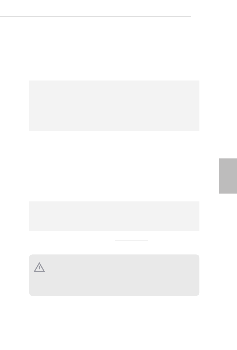
E3V5 WS
BIOS
Özelliği
Donanım
Monitörü
OS
Belgeler
•Çok dilli GUI desteği ile AMI UEFI Legal BIOS
•ACPI 5.0 Uyumlu uyandırma olayları
•SMBIOS 2.7 Desteği
•CPU, DRAM, VPPM, PCH 1.0V, VCCIO, VCCSA Gerilimi
Çoklu Ayarlama
•CPU/Kasa sıcaklığı tespiti
•CPU/Kasa Fanı Devirölçer
•CPU/Kasa Sessiz Fan (İşlemci sıcaklığıyla otomatik ayarlı kasa
fanı hızı)
•CPU/Kasa Fanı çoklu hız kontrolü
•Voltaj izleme: +12V, +5V, +3,3V, CPU Vcore
•Microso® Windows® 10 64 bit / 8.1 64 bit / 7 32 bit / 7 64 bit /
Server 2012 R2 64 bit / Server 2012 64 bit / Server 2008 R2 64
bit
* Windows® 7 işletim sistemini yüklemek için, ISO dosyasında
sıkıştırılmış xHCI sürücülerine sahip değiştirilmiş yükleme diski
gereklidir. Daha ayrıntılı talimatlar için lütfen 125. sayfaya
başvurun.
* Güncellenmiş Windows® 10 sürücüsü konusunda ayrıntılar için
lütfen ASRock web sitesini ziyaret edin: http://www.asrock.com
•FCC, CE, WHQL
•ErP/EuP için hazır (ErP/EuP için hazır güç beslemesi
gereklidir)
Türkçe
* Detaylı ürün bilgisi için, lütfen web sitemizi ziyaret edin: http://www.asrock.com
Lütfen, BIOS ayarlarını düzenleme, Bağımsız Hız Aşırtma Teknolojinin uygulanması
ya da üçüncü kişilerin hız aşırtma araçlarının kullanılması da dahil olmak üzere tüm
hız aşırtma işlemlerinin belirli bir risk taşıdığını unutmayın. Hız aşırtma, sisteminizin
dayanıklılığını etkileyebilir, hatta sisteminizde yer alan bileşen ve aygıtlara zarar verebilir. Bunu riski ve masraarı size ait olmak üzere gerçekleştirilmelidir. Hız aşırtmadan
doğabilecek zararlar konusunda sorumlu olmayacağız.
79
Page 82

1.3 Bağlantı Teli Kurulumu
Çizim, bağlantı tellerinin kurulumunu göstermektedir. Tel kapağı, pimlerin üzerine
yerleştirildiğinde, tel "Kısa" olur. Pimlerin üzerinde tel kapağı bulunmadığında, tel
"Açık" olur. Çizim, pin1 ve pin2 alanları "Kısa" olan ve bu iki pim üzerinde bir bağlantı
teli kapağı bulunan 3-pin bağlantı telini göstermektedir.
CMOS'u Temizle Bağlantı Teli
(CLRMOS1)
(bkz. sf.1, No. 8)
CMOS'u TemizleVarsayılan
Türkçe
CLRMOS1, CMOS verilerini temizlememizi sağlar. Sistem parametrelerini temizlemek
ve varsayılan kurulum ayarlarına sıfırlamak için, lütfen bilgisayarı kapatın ve güç
kablosunu güç beslemesinden çekin. 15 saniye bekledikten sonra, CLRMOS1
üzerindeki pin2 ve pin3'ü 5 saniye boyunca kısaltmak için bir bağlantı teli kullanın.
Ancak, CMOS'u lütfen BIOS'u güncelledikten hemen sonra temizlemeyin. +BIOS'u
güncelledikten hemen sonra CMOS'u temizlemeniz gerekirse, önce sistemi başlatın
ve ardından CMOS temizleme işlemi öncesinde yeniden kapatın. Lütfen, parola,
tarih, saat ve varsayılan kullanıcı prolinin yalnızca CMOS bataryası çıkarıldığında
temizleneceğini unutmayın.
80
Page 83
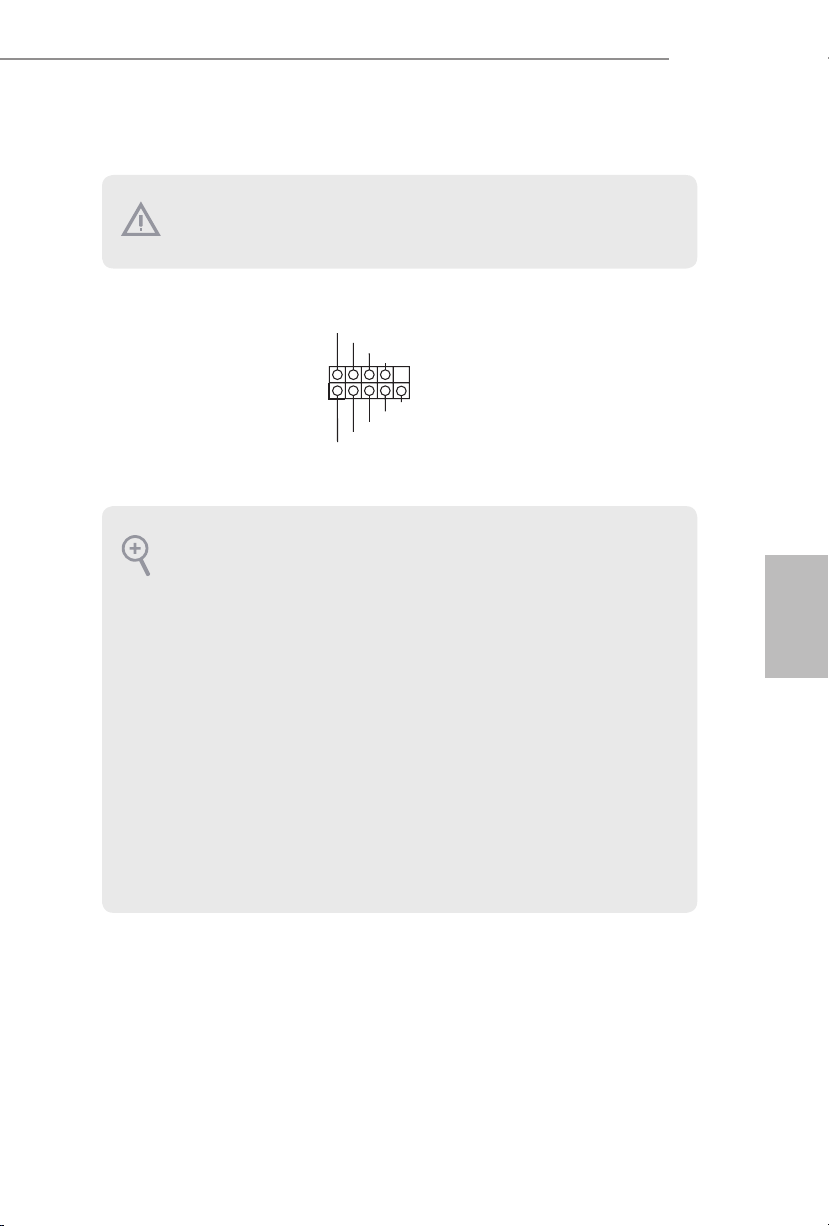
1.4 Ekli Bağlantılar ve Bağlayıcılar
Ekli bağlantılar ve bağlayıcılar bağlantı teli değildir. Bağlantı teli kapaklarını bu
bağlantı ve bağlayıcılar üzerine yerleştirmeyin. Bağlantı teli kapaklarının bağlantılar ile
bağlayıcılar üzerine yerleştirilmesi, anakarta kalıcı hasar verebilir.
E3V5 WS
Sistem Paneli Bağlantısı
(9-pin PANEL1)
(bkz sf.1, No. 13)
PWRBTN (Güç Anahtarı):
Güç anahtarını kasa ön paneline bağlayın. Güç anahtarını kullanarak sistemin hangi
yöne hareketle kapanacağını seçebilirsiniz.
RESET (Sıfırlama Anahtarı):
Sıfırlama anahtarını kasa ön paneline bağlayın. Bilgisayarın kilitlenmesi ve normal
şekilde yeniden başlatılamaması halinde reset (sıfırla) düğmesine basın.
PLED (Sistem Güç LED'i):
Güç durumu göstergesini kasa ön paneline bağlayın. Sistem çalışırken LED ışığı
yanacaktır. Sistem S1/S3 uyku durumdayken LED ışığı yanıp söner. Sistem S4 uyku
durumunda ya da kapalıyken (S5) LED ışık kapanır.
HDLED (Sabit Disk Etkinlik LED'i):
Sabit sürücü etkinlik LED'ini kasa ön paneline bağlayın. Sabit sürücü veri okur ya da
yazarken LED ışığı yanar.
Ön panel tasarımı kasaya göre değişiklik gösterebilir. Bir ön panel modülü, temel olarak
bir güç anahtarı, sıfırlama anahtarı, güç LED'i, sabit sürücü aktivitesi LED'i, hoparlör
gibi birimlerden oluşur. Kasanızın ön panel modülünü bu bağlantıya takmadan önce,
kablo düzenlemeleri ile pin düzenlemelerinin düzgün şekilde yapıldığından emin olun.
1
PLE D+
PLE D-
HDL ED-
HDL ED+
PWR BTN#
GND
GND
RES ET#
GND
Güç anahtarını bağlayın,
kasa üzerindeki anahtar ile
sistem durumu belirtecini
aşağıdaki pim düzenine
göre sıfırlayın. Kabloları
bağlarken pozitif ve negatif
pimleri not edin.
Türkçe
81
Page 84

Güç LED’i ve Hoparlör
PLE D-
Bağlantısı
(7-pin SPK_PLED1)
(bkz. sf.1, No. 11)
DUM MY
+5V
1
PLE D+
SPE AKER
DUM MY
PLE D+
Lütfen kasa güç LED’ini
ve kasa hoparlörünü bu
bağlantıya takın.
Seri ATA3 Bağlayıcıları
(SATA3_0:
bkz. sf.1, No. 12)
(SATA3_1:
bkz. sf.1, No. 14)
(SATA3_2:
SATA3_2SATA3_4
SATA3_3SATA3_5
SATA3_0
SATA3_1
Bu altı SATA3 bağlayıcısı,
veri aktarım hızı 6,0 Gb/
sn'ye kadar olan dahili
depolama aygıtları için
tasarlanmış SATA veri
kablolarını destekler.
bkz. sf.1, No. 9)
(SATA3_3:
bkz. sf.1, No. 15)
Türkçe
(SATA3_4:
bkz. sf.1, No. 17)
(SATA3_5:
bkz. sf.1, No. 16)
USB 2.0 Bağlantıları
(9-pin USB2_3)
(bkz. sf.1, No. 18)
(9-pin USB4_5)
(bkz. sf.1, No. 19)
USB 3.0 Bağlantı
(19-pin USB3_4_5)
(bkz. sf.1, No. 6)
IntA _P_ D+
1
ID
USB _PWR
1
USB _PWR
IntA _P_ D-
GND
IntA _P_ D-
IntA _P_ D+
P-
P+
P+
P-
IntA _P_ SSTX +
IntA _P_ SSTX -
GND
IntA _P_ SSTX -
IntA _P_ SSTX +
GND
GND
DUM MY
GND
IntA _P_ SSRX +
IntA _P_ SSR X-
Vbus
IntA _P_ SSR X-
IntA _P_ SSRX +
GND
Bu anakartta iki başlık
vardır. Her USB 2.0
bağlantısı, iki adet bağlantı
noktasını destekleyebilir.
Bu anakart üzerinde, G/Ç
paneli üzerindeki dört USB
3.0 bağlantı noktasının
yanı sıra bir adet bağlantı
bulunmaktadır. Her
USB 3.0 bağlantısı, iki
Vbus
adet bağlantı noktasını
destekleyebilir.dört
82
Page 85
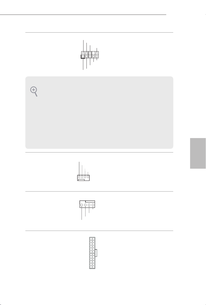
E3V5 WS
4 3 2 1
Ön Panel Ses Bağlantısı
(9-pin HD_AUDIO1)
(bkz. sf.1, No. 21)
1. Yüksek Tanımlı Ses, Jak Algılama özelliğini destekler, ancak bu işlevin düzgün
çalışabilmesi için kasa üzerindeki panel kablosunun HDA işlevini desteklemesi
gerekmektedir. Sisteminizi kurarken, lütfen kılavuzumuzdaki talimatlar ile kasa
kılavuzundaki talimatları izleyin.
2. AC'97 ses paneli kullanıyorsanız, lütfen aşağıdaki adımları uygulayarak ön panel ses
bağlantısına takın:
A. Mic_IN'i (MIC) MIC2_L'ye bağlayın.
B. Audio_R'yi (RIN) OUT2_R'ye ve Audio_L'yi (LIN) OUT2_L'ye bağlayın.
C. Toprak'ı (GND) Toprak'a (GND) bağlayın.
D. MIC_RET ve OUT_RET yalnızca HD ses paneli içindir. AC'97 ses paneli için
bunları bağlamanıza gerek yoktur.
E. Ön mikrofonu etkinleştirmek için, Realtek Kontrol panelinde “FrontMic” sekmesine
gidin ve “Kayıt Ses Seviyesi”ni ayarlayın.
Kasa Fanı Bağlayıcıları
(4-pin CHA_FAN1)
(bkz sf.1, No. 7)
(4-pin CHA_FAN2)
(bkz sf.1, No. 10)
1
MIC 2_L
GND
FAN _VO LTA GE
CHA _FA N_S PEE D
GND
PRE SENCE #
MIC _RET
OUT _RET
OUT 2_L
J_S ENSE
OUT 2_R
MIC 2_R
FAN _SP EED _CO NTR OL
Bu bağlantı, ses aygıtlarının
ön ses paneline bağlanması
içindir.
Lütfen fan kablolarını
fan bağlayıcılarına takın
ve siyah teli topraklama
pinine bağlayın.
Türkçe
CPU Fan Bağlayıcıları
(4-pin CPU_FAN1)
(bkz sf.1, No. 2)
ATX Güç Bağlayıcısı
(24-pin ATXPWR1)
(bkz. sf.1, No. 5)
GND
FAN _VOLT AGE
CPU _F
AN_ SPEED
FAN_ SPEED _CONT ROL
24
12
1
13
Bu anakart, 4-Pin CPU
fan (Sessiz Fan) bağlayıcısı
sağlamaktadır. 3-Pin CPU
fan bağlamak istiyorsanız,
lütfen Pin 1-3'ü kullanın.
Bu anakart, 24-pin ATX
güç bağlayıcısı
sağlamaktadır. 20-pin ATX
güç beslemesi kullanmak
için, lütfen Pin 1 ve Pin
13'e bağlayın.
83
Page 86
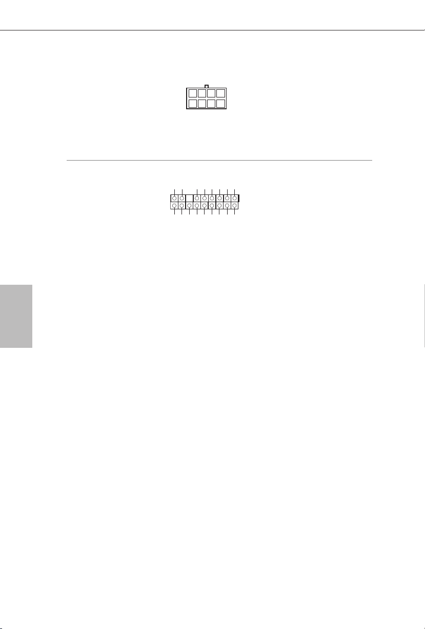
ATX 12V Güç Bağlayıcısı
5
1
8
(8-pin ATX12V1)
(bkz. sf.1, No. 1)
Bu anakart, 8-pin ATX
12V güç bağlayıcısı
sağlamaktadır. 4-pin ATX
güç beslemesi kullanmak
için, lütfen Pin 1 ve Pin 5'e
bağlayın.
TPM bağlantısı
(17-pin TPMS1)
(bkz. sf.1, No. 20)
GN D
LAD 0
LAD 3
+3 V
+3V S B
D
GN
SER IRQ #
PC IRS T #
GN D
LAD 1
LAD 2
S_P WRD WN #
SMB _DA TA_M AIN
Bu bağlayıcı, anahtarlar, dijital
PC ICL K
FRA M E
sertikalar, parolalar ve verileri
1
güvenli bir şekilde saklama
özelliği bulunan Güvenilir Plat-
GN D
form Modülü (TPM) sistemini
destekler. TPM sistemleri, aynı
SMB _CL K_MA IN
zamanda ağ güvenliğinin
artırılması, dijital kimliklerin korunması ve platform
bütünlüğünün sağlanmasına da
Türkçe
yardımcıdır.
84
Page 87

1 개요
ASRock E3V5 WS 마더보드를 구입해 주셔서 감사합니다 . 이 마더보드는
ASRock 의 일관되고 엄격한 품질관리 하에 생산되어 신뢰성이 우수합니다 . 품
질과 내구성에 대한 ASRock 의 기준에 부합하는 우수한 성능과 견고한 설계를
제공합니다 .
마더보드 규격과 BIOS 소프트웨어를 업데이트할 수도 있기 때문에 , 이 문서의
내용은 예고 없이 변경될 수 있습니다 . 이 설명서가 변경될 경우 , 업데이트된 버
전은 ASRock 의 웹사이트에서 추가 통지 없이 제공됩니다 . 이 마더보드와 관련
하여 기술적 지원이 필요한 경우 , 당사의 웹사이트를 방문하여 사용 중인 모델
에 대한 구체적 정보를 구하십시오 . ASRock 의 웹사이트에서는 최신 VGA 카드
와 CPU 지원 목록도 찾을 수 있습니다 . ASRock 웹사이트 http://www.asrock.com.
1.1 포장 내용물
•
ASRock E3V5 WS 마더보드 (ATX 폼 팩터 )
•
ASRock E3V5 WS 간편 설치 안내서
•
ASRock E3V5 WS 지원 CD
•
시리얼 ATA (SATA) 데이터 케이블 2 개 ( 선택 품목 )
•
I/O 패널 실드 1 개
E3V5 WS
한 국 어
85
Page 88
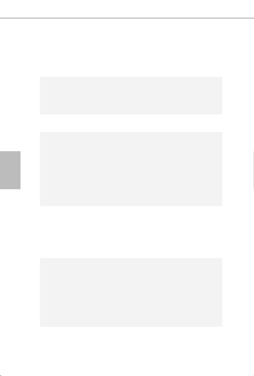
한 국 어
1.2 규격
플랫폼
CPU
칩세트
메모리
확장 슬롯
•
ATX 폼 팩터
•
솔리드 콘덴서 구조
•
Intel® Xeon® E3-1200 v5 프로세서 및 6 세대 Intel® CoreTM i7/
i5/i3/Pentium®/Celeron® 프로세서 ( 소켓 1151) 지원
•
5 개 전원 위상 구조
•
Intel® Turbo Boost 2.0 기술 지원
•
Intel® C232
•
듀얼 채널 DDR4 메모리 기술
•
DDR4 DIMM 슬롯 4 개
•
DDR4 2133 비 ECC, 비버퍼링 메모리 지원
•
ECC UDIMM 메모리 모듈 지원
* ECC 은 Intel® E3/CoreTM i3/Pentium®/Celeron® CPU 에서만 지
원됩니다 . Intel® CoreTM i7/i5 CPU, ECC 는 지원되지 않습니다 .
•
시스템 메모리 최대 용량 : 64GB
•
Intel® Extreme Memory Prole (XMP) 2.0 지원
•
DIMM 슬롯에 15 μ Gold Contact 장착
•
PCI Express 3.0 x16 슬롯 2 개 (PCIE2:x16 모드 , PCIE4:x4 모
드 )*
* NVMe SSD 를 부팅 디스크로 사용 가능하도록 지원
•
PCI Express 3.0 x1 슬롯 3 개 (Flexible PCIe)
•
AMD Quad CrossFireXTM 및 CrossFireXTM 지원
•
VGA PCIe 슬롯에 15 μ Gold Contact 장착 (PCIE2)
86
오디오
•
7.1 CH HD 오디오 콘텐츠 보호를 이용한 지원 (Realtek
ALC892 오디오 코덱 )
*7.1 CH HD 오디오를 구성하려면 HD 전면 패널 오디오 모듈
을 사용하고 다채널 오디오 기능을 오디오 드라이버로 활성화
해야 합니다 .
•
프리미엄 Blu-ray 오디오 지원
•
서지 보호 지원 (ASRock 풀 스파이크 보호 )
•
ELNA 오디오 캡
Page 89

LAN
후면 패널
I/O
저장 장치
•
Gigabit LAN 10/100/1000 Mb/s
•
Giga PHY Intel® I219LM
•
Wake-On-LAN 지원
•
번개 /ESD 보호 지원 (ASRock 풀 스파이크 보호 )
•
절전형 이더넷 802.3az 지원
•
PXE 지원
•
PS/2 마우스 포트 1 개
•
PS/2 키보드 포트 1 개
•
USB 2.0 포트 2 개 (ESD 보호 지원 (ASRock 풀 스파이크 보
호 ))
•
USB 3.0 포트 4 개 (ESD 보호 지원 (ASRock 풀 스파이크 보
호 ))
•
LED 장착 RJ-45 LAN 포트 1 개 (ACT/LINK LED 및 SPEED
LED)
•
HD 오디오 잭 : 라인 입력 / 전면 스피커 / 마이크
•
지원 SATA3 6.0 Gb/s 커넥터 6 개가 RAID (RAID 0, RAID 1,
RAID 5, RAID 10, Intel RSTe), NCQ, AHCI 및 핫 플러그 지
원
E3V5 WS
한 국 어
커넥터
•
TPM 헤더 1 개
•
전원 LED 및 스피커 헤더 1 개
•
CPU 팬 커넥터 (4 핀 ) 1 개 ( 스마트 팬 속도 제어 )
•
섀시 팬 커넥터 (4 핀 ) 2 개 ( 스마트 팬 속도 제어 )
•
24 핀 ATX 전원 커넥터 1 개
•
8 핀 12V 전원 커넥터 1 개
•
전면 패널 오디오 커넥터 1 개
•
USB 2.0 헤더 2 개 (USB 2.0 포트 4 개 지원 )(ESD 보호 지원
(ASRock 풀 스파이크 보호 ))
•
USB 3.0 헤더 1 개 (USB 3.0 포트 2 개 지원 )(ESD 보호 지원
(ASRock 풀 스파이크 보호 ))
87
Page 90
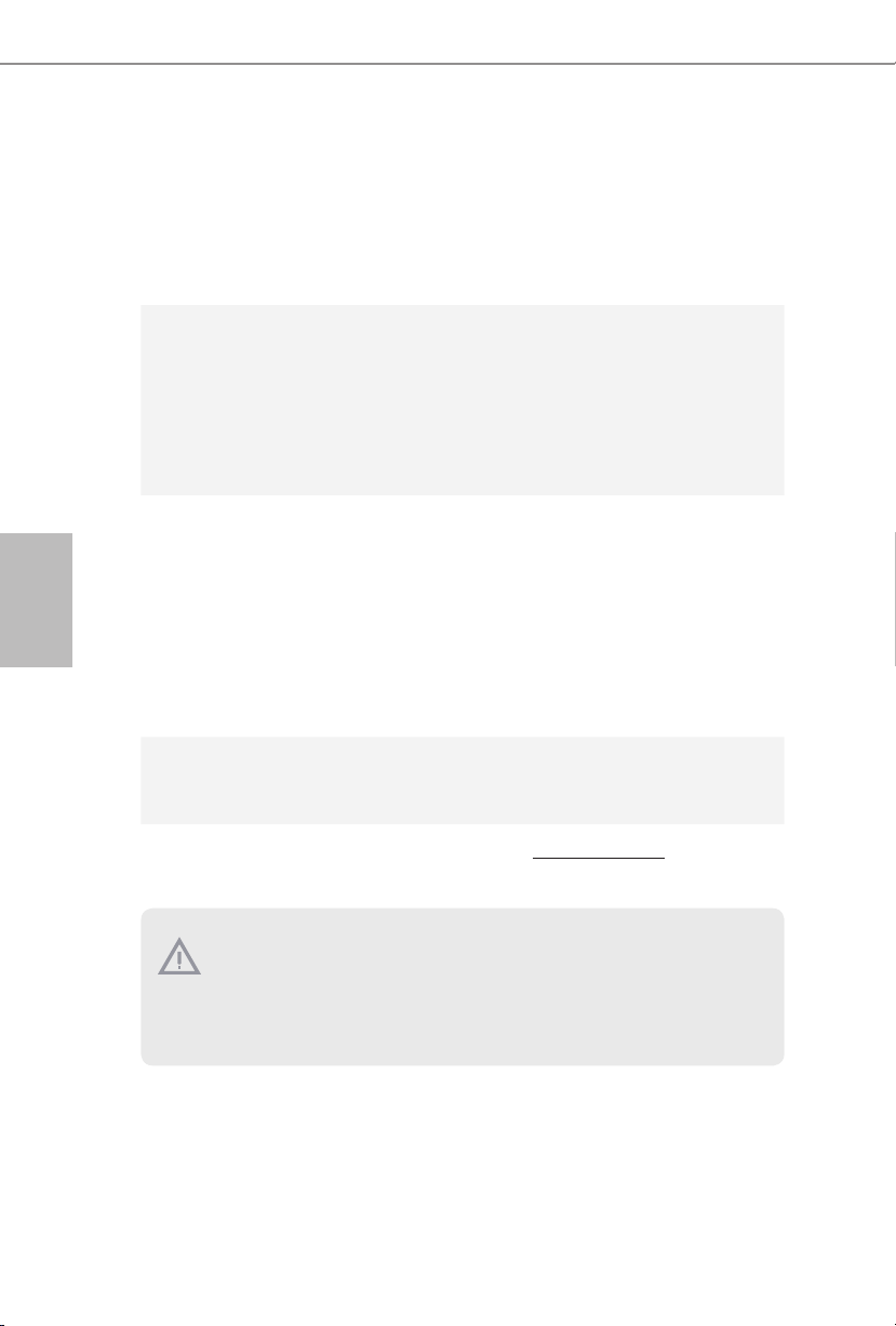
한 국 어
BIOS 기능
하드웨어
모니터
OS
인증
•
다국어 GUI 지원을 제공하는 AMI UEFI 적합형 BIOS
•
ACPI 5.0 준수 웨이크 업 이벤트
•
SMBIOS 2.7 지원
•
CPU, DRAM, VPPM, PCH 1.0V, VCCIO, VCCSA 전압 다중
조정
•
CPU/ 섀시 온도 감지
•
CPU/ 섀시 팬 타코미터
•
CPU/ 섀시 저소음 팬 (CPU 온도에 의한 섀시 팬 속도 자동
조절 )
•
CPU/ 섀시 팬 다중 속도 조절
•
전압 모니터링 : +12V, +5V, +3.3V, CPU Vcore
•
Microso® Windows® 10 64 비트 / 8.1 64 비트 / 7 32 비트 / 7
64 비트 / 서버 2012 R2 64 비트 / 서버 2012 64 비트 / 서버
2008 R2 64 비트
* Windows® 7 OS 를 설치하려면 , xHCI 드라이버를 ISO 파일에
포함시킨 수정된 설치 디스크가 필요합니다 . 자세한 사용법
은 125 페이지를 참조하십시오 .
* 업데이트된 Windows® 10 드라이브의 자세한 내용은 다음의
ASRock 웹사이트를 참조하십시오 . http://www.asrock.com
•
FCC, CE, WHQL
•
ErP/EuP 사용 가능(ErP/EuP 사용 가능 전원공급장치 필요 )
* 자세한 제품 정보에 대해서는 당사 웹사이트를 참조하십시오 : http://www.asrock.com
BIOS 설정을 조정하거나 Untied Overclocking Technology 를 적용하거나 타업체
의 오버클로킹 도구를 사용하는 것을 포함하는 오버클로킹에는 어느 정도의 위
험이 따른다는 것을 유념하십시오 . 오버클로킹은 시스템 안정성에 영향을 주거
나 심지어 시스템의 구성 요소와 장치에 손상을 입힐 수도 있습니다 . 오버클로
킹은 사용자 스스로 위험과 비용을 감수하고 해야 합니다 . 당사는 오버클로킹
에 의해 발생할 수 있는 손상에 대해서 책임이 없습니다 .
88
Page 91
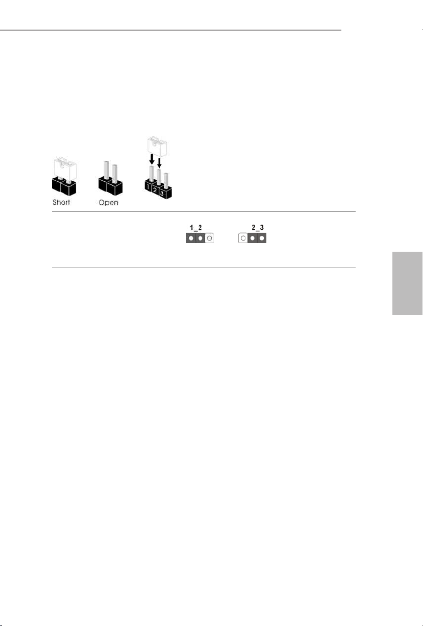
1.3 점퍼 설정
그림은 점퍼를 어떻게 설정하는지 보여줍니다 . 점퍼 캡을 핀에 씌우면 점퍼가
“단락” 됩니다 . 점퍼 캡을 핀에 씌우지 않으면 점퍼가 “단선”됩니다 . 그림은 3
핀 점퍼를 보여주며 핀 1 과 핀 2 는 점퍼 캡을 씌울 때 “단락”됩니다 .
Clear CMOS 점퍼
(CLRMOS1)
(1 페이지 , 8 번 항목 참조 )
CLRMOS1 을 사용하여 CMOS 에 저장된 데이터를 지울 수 있습니다 . 시스
템 파라미터를 지우고 기본 설정으로 초기화하려면 컴퓨터를 끄고 전원 코
드를 전원공급장치에서 빼십시오 . 15 초 동안 기다린 후 점퍼 캡을 사용하
여 CLRMOS1 의 핀 2 와 핀 3 을 5 초 동안 단락시키십시오 . 그러나 BIOS 업데
이트 직후에는 CMOS 를 삭제하지 마십시오 . BIOS 업데이트를 완료한 직후
CMOS 를 지워야 할 경우 , 우선 시스템을 부팅한 후 바이오스 업데이트를 종
료한 다음 CMOS 지우기 작업을 해야 합니다 . CMOS 배터리를 제거할 경우에
만 암호 , 날짜 , 시간 , 사용자 기본 프로파일이 지워집니다 .
Clear CMOS기본값
E3V5 WS
한 국 어
89
Page 92

1.4 온보드 헤더 및 커넥터
온보드 헤더와 커넥터는 점퍼가 아닙니다 . 점퍼 캡을 온보드 헤더와 커넥터에
씌우지 마십시오 . 점퍼 캡을 온보드 헤더와 커넥터에 씌우면 마더보드가 영구
적으로 손상됩니다 .
한 국 어
시스템 패널 헤더
(9 핀 PANEL1)
(1 페이지, 13 번 항목 참조 )
PWRBTN( 전원 스위치 ):
섀시 전면 패널의 전원 스위치에 연결합니다 . 전원 스위치를 이용해 시스템을 끄는
방법을 구성할 수 있습니다 .
RESET( 리셋 스위치 ):
섀시 전면 패널의 리셋 스위치에 연결합니다 . 컴퓨터가 정지하고 정상적 재시작을
수행하지 못할 경우 리셋 스위치를 눌러 컴퓨터를 재시작합니다 .
PLED( 시스템 전원 LED):
섀시 전면 패널의 전원 상태 표시등에 연결합니다 . 시스템이 작동하고 있을 때는
LED 가 켜져 있습니다 . 시스템이 S1/S3 대기 상태에 있을 때는 LED 가 계속 깜박입니
다 . 시스템이 S4 대기 상태 또는 전원 꺼짐 (S5) 상태에 있을 때는 LED 가 꺼져 있습니
다 .
HDLED( 하드 드라이브 동작 LED):
섀시 전면 패널의 하드 드라이브 동작 LED 에 연결합니다 . 하드 드라이브가 데이터
를 읽거나 쓰고 있을 때 LED 가 켜져 있습니다 .
전면 패널 디자인은 섀시별로 다를 수 있습니다 . 전면 패널 모듈은 주로 전원 스위치 ,
리셋 스위치 , 전원 LED, 하드 드라이브 동작 LED, 스피커 등으로 구성되어 있습니다 .
섀시 전면 패널 모듈을 이 헤더에 연결할 때 와이어 할당과 핀 할당이 정확히 일치하
는지 확인합니다 .
1
PLE D+
PLE D-
HDL ED-
HDL ED+
PWR BTN#
GND
RES ET#
GND
GND
섀시의 전원 스위치 ,
리셋 스위치 , 시스템
상태 표시등을 아래의
핀 할당에 따라 이 헤
더에 연결합니다 . 케이
블을 연결하기 전에 양
극 핀과 음극 핀을 기
록합니다 .
90
Page 93

E3V5 WS
PLE D-
IntA _P_ D+
전원 LED 및 스피커 헤더
(7 핀 SPK_PLED1)
(1 페이지 , 11 번 항목 참조 )
시리얼 ATA3 커넥터
(SATA3_0: 1 페이지 ,
12 번 항목 참조 )
(SATA3_1: 1 페이지 ,
14 번 항목 참조 )
(SATA3_2: 1 페이지 ,
9 번 항목 참조 )
(SATA3_3: 1 페이지 ,
15 번 항목 참조 )
(SATA3_4: 1 페이지 ,
17 번 항목 참조 )
(SATA3_5: 1 페이지 ,
16 번 항목 참조 )
USB 2.0 헤더
(9 핀 USB2_3)
(1 페이지 , 18 번 항목 참조 )
(9 핀 USB4_5)
(1 페이지 , 19 번 항목 참조 )
DUM MY
+5V
1
USB _PWR
1
USB _PWR
SPE AKER
DUM MY
PLE D+
PLE D+
SATA3_2SATA3_4
SATA3_3SATA3_5
P-
P+
P+
P-
GND
GND
SATA3_0
SATA3_1
DUM MY
섀시 전원 LED 와
섀시 스피커를 이
헤더에 연결하십
시오 .
이들 6 개의
SATA3 커넥터는
최대 6.0 Gb/s 데이
터 전송 속도를 제
공하는 내부 저장
장치용 SATA 데이
터 케이블을 지원
합니다 .
한 국 어
이 마더보드에는
헤더 두 개가 있습
니다 . 각 USB 2.0
헤더는 포트 두 개
를 지원할 수 있습
니다 .
USB 3.0 헤더
(19 핀 USB3_4_5)
(1 페이지 , 6 번 항목 참조 )
1
IntA _P_ D-
IntA _P_ D+
ID
GND
IntA _P_ SSTX +
IntA _P_ SSTX -
IntA _P_ SSTX +
GND
IntA _P_ D-
GND
IntA _P_ SSRX +
IntA _P_ SSR X-
IntA _P_ SSRX +
GND
IntA _P_ SSTX -
Vbus
Vbus
IntA _P_ SSR X-
I/O 패널에 USB
3.0 포트 네 개가
개가 탑재되어 있
을 뿐 아니라 마더
보드에 헤더 한 개
가 탑재되어 있습
니다 . 각 USB 3.0
헤더는 포트 두 개
를 지원할 수 있습
니다 .
91
Page 94
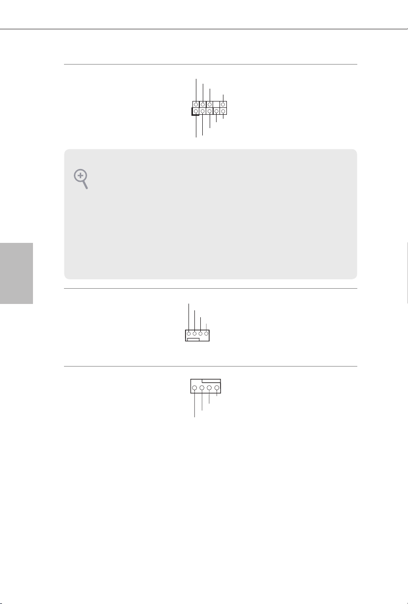
한 국 어
전면 패널 오디오 헤더
(9 핀 HD_AUDIO1)
(1 페이지 , 21 번 항목 참조 )
1.
고음질 오디오는 잭 감지를 지원하지만 올바르게 작동하려면 섀시의 패널 와이어
가 HDA 를 지원해야 합니다 . 설명서 및 섀시 설명서에 나와 있는 지침을 따라 시스
템을 설치하십시오 .
2.
AC’ 97 오디오 패널을 사용할 경우 아래와 같은 절차를 따라 전면 패널 오디오 헤
더에 설치하십시오 :
A. Mic_IN (MIC) 를 MIC2_L 에 연결합니다 .
B. Audio_R (RIN)을 OUT2_R 에 연결하고 Audio_L (LIN) 을 OUT2_L에 연결합니다 .
C. 접지 (GND) 를 접지 (GND) 에 연결합니다 .
D. MIC_RET 및 OUT_RET 는 HD 오디오 패널에만 사용됩니다 . AC’ 97 오디오 패
널용으로 연결할 필요가 없습니다 .
E. 전면 마이크를 활성화하려면 Realtek 제어판에서 “ FrontMic” 탭으로 가서
“ Recording Volume( 녹음 볼륨 )” 을 조정합니다 .
1
GND
PRE SENCE #
MIC 2_R
MIC 2_L
MIC _RET
J_S ENSE
OUT 2_R
OUT _RET
OUT 2_L
이 헤더는 오디오
장치를 전면 오디
오 패널에 연결하
는 데 사용됩니다 .
92
섀시 팬 커넥터
(4 핀 CHA_FAN1)
(1 페이지 , 7 번 항목 참조 )
(4 핀 CHA_FAN2)
(1 페이지 , 10 번 항목 참조 )
CPU 팬 커넥터
(4 핀 CPU_FAN1)
(1 페이지 , 2 번 항목 참조 )
GND
FAN _VO LTA GE
CHA _FA N_S PEE D
FAN _SP EED _CO NTR OL
4 3 2 1
GND
FAN _VOLT AGE
CPU _F
AN_ SPEED
FAN_ SPEED _CONT ROL
팬 케이블을 팬 커
넥터에 연결하고
검은색 와이어를
접지핀에 연결하
십시오 .
이 마더보드에는
4 핀 CPU 팬 ( 저
소음 팬 ) 커넥터
가 탑재되어 있습
니다 . 3 핀 CPU 팬
을 연결하려는 경
우 핀 1-3 에 연결
하십시오 .
Page 95

E3V5 WS
5
1
8
ATX 전원 커넥터
(24 핀 ATXPWR1)
(1 페이지 , 5 번 항목 참조 )
ATX 12V 전원 커넥터
(8 핀 ATX12V1)
(1 페이지 , 1 번 항목 참조 )
TPM 헤더
(17 핀 TPMS1)
(1 페이지 , 20 번 항목 참조 )
24
12
이 마더보드에는 24 핀
ATX 전원 커넥터가 탑
재되어 있습니다 . 20
핀 ATX 전원공급장치
를 사용하려면 핀 1 과
1
13
핀 13 을 따라 연결하
십시오 .
이 마더보드에는 8 핀
ATX 12V 전원 커넥터
가 탑재되어 있습니
다 . 4 핀 ATX 전원공
급장치를 사용하려면
핀 1 과 핀 5 을 따라 연
결하십시오 .
이 커넥터는 키 , 디지털
GN D
LAD 0
+3 V
+3V S B
D
GN
GN D
LAD 1
SER IRQ #
S_P WRD WN #
PC ICL K
LAD 3
PC IRS T #
FRA M E
인증서 , 암호 및 데이터
1
를 안전하게 보관할 수 있
는 TPM(Trusted Platform
GN D
LAD 2
Module) 시스템을 지원합니
한 국 어
다 . TPM 시스템은 네트워크
SMB _CL K_MA IN
SMB _DA TA_M AIN
보안을 강화하고 , 디지털 신
원을 보호하며 플랫폼 무결
성을 유지합니다 .
93
Page 96
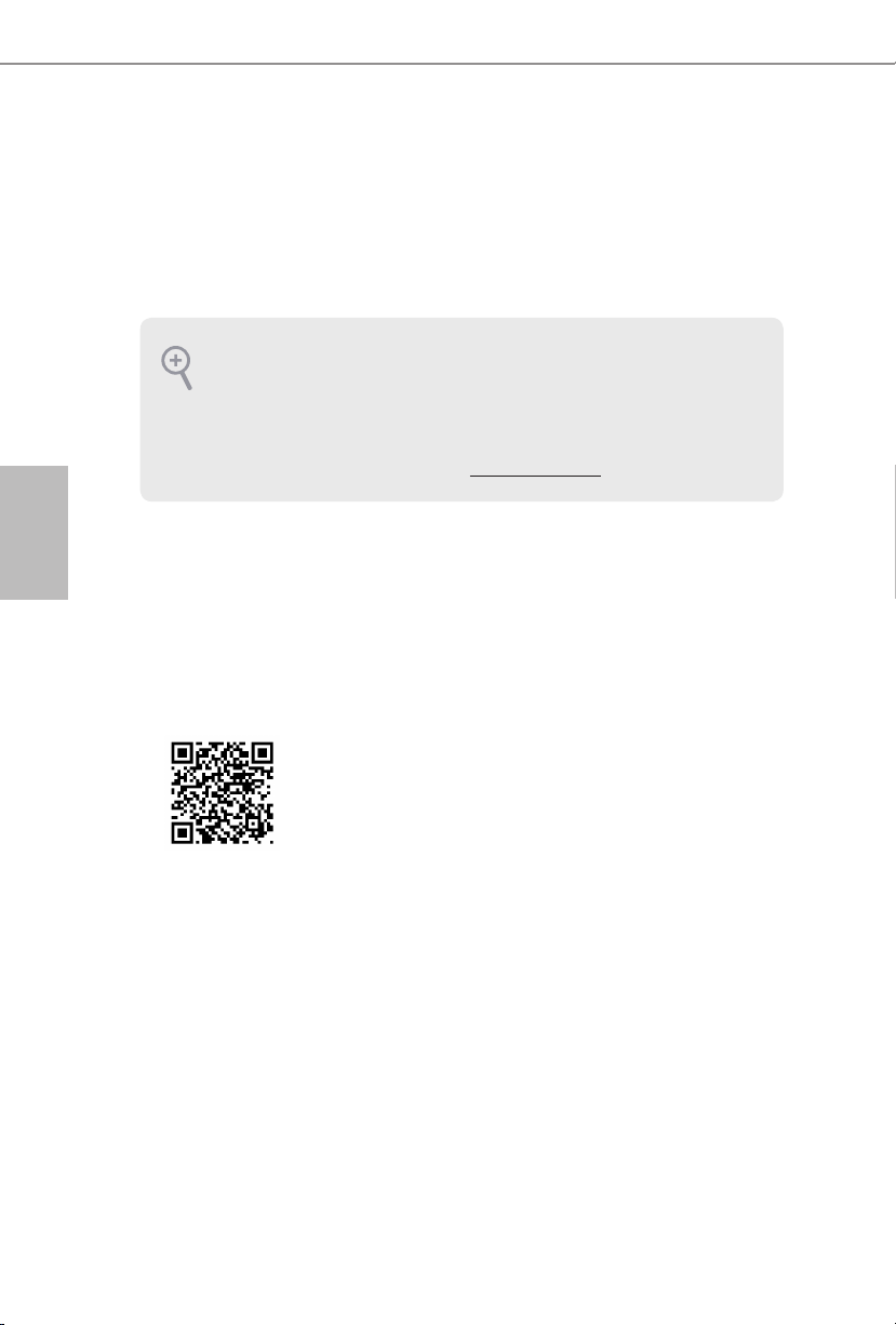
日本語
1 はじめに
ASRock E3V5 WS マザーボードをお買い上げいただきまして誠にありがとうござ
います。ASRock E3V5 WS マザーボードは、ASRock の一貫した厳格な品質管理の
下で製造された信頼性の高いマザーボードです。ASRock の品質と耐久性の取り
組みに準拠した堅牢な設計を持つ、優れたパフォーマンスを提供します。
マザーボードの仕様とBIOS ソフトウェアは更新されることがあるため、このマニュ
アルの内容は予告なしに変更することがあります。このマニュアルの内容に変更が
あった場合には、更新されたバージョンは、予告なくASRock のウェブサイトから
入手できるようになります。このマザーボードに関する技術的なサポートが必要な
場合には、ご使用のモデルについての詳細情報を、当社のウェブサイトで参照くだ
さい。ASRock のウェブサイトでは、最新のVGA カードおよびCPU サポート一覧
もご覧になれます。ASRock ウェブサイト http://www.asrock.com.
1.1 パッケージの内容
•
ASRock E3V5 WS マザーボード(ATX フォームファクタ)
•
ASRock E3V5 WS クイックインストールガイド
•
ASRock E3V5 WS サポート CD
•
2 x シリアルATA(SATA)データケーブル(オプション)
•
1 x I/O パネルシールド
ユーザーマニュアル
94
Page 97

1.2 仕様
プラット
フォーム
CPU
チップセット
メモリ
•
ATX フォームファクター
•
固体コンデンサ設計
•
Intel® Xeon® E3-1200 v5 プロセッサーに、および、第 6 世代
Intel® Core
(ソケット 1151)
•
5 電源フェーズ設計
•
Intel® ターボブースト2.0 テクノロジーをサポート
•
Intel® C232
•
デュアルチャンネル DDR4 メモリテクノロジー
•
4 x DDR4 DIMM スロット
•
DDR4 2133 ノン ECC、アンバッファードメモリに対応
•
ECC UDIMM メモリモジュールに対応
* ECC はIntel® E3/CoreTM i3/Pentium®/Celeron® CPU でのみサ
ポートされます。 Intel® CoreTM i5/i7 CPU では、ECC をサポート
していません。
•
システムメモリの最大容量: 64GB
•
Intel® エクストリームメモリプロファイル(XMP)2.0 に対応
•
DIMM スロットに 15 μゴールドコンタクトを採用
TM
i7/i5/i3/Pentium®/Celeron® プロセッサーに対応
E3V5 WS
日本語
拡張スロット
オーディオ
•
2 x PCI Express 3.0 x16 スロット(PCIE2: x16 モード、PCIE4:
x4 モード)*
* 起動ディスクとして NVMe SSD に対応
•
3 x PCI Express 3.0 x1 スロット(Flexible PCIe)
•
AMD Quad CrossFireX
•
VGA PCIe スロットに 15 μ ゴールドコンタクトを採用
(PCIE2)
•
7.1 CH HD オーディオ、コンテンツプロテクション付き
(Realtek ALC892 オーディオコーデック)
*7.1 CH HD オーディオを設定するためには、HD フロントパネ
ルのオーディオモジュールを使用し、オーディオドライバを通し
てマルチチャンネルオーディオ機能を有効にする必要があり
ます。
•
プレミアム・ブルーレイ・オーディオ・サポート
•
サージ保護に対応(ASRock 完全スパイク保護)
•
ELNA 製オーディオコンデンサ
TM
と CrossFireXTM をサポート
95
Page 98

日本語
LAN
リアパネル
I/O
ストレージ
コネクタ
•
ギガビットLAN 10/100/1000 Mb/s
•
ギガ PHY Intel® I219LM
•
Wake-On-LAN(ウェイク オン ラン)に対応
•
雷/ 静電気放電(ESD)保護に対応(ASRock 完全スパイク
保護)
•
エネルギー効率のよいイーサネット802.3az をサポート
•
PXE をサポート
•
1 x PS/2 マウスポート
•
1 x PS/2 キーボードポート
•
2 x USB 2.0 ポート((静電気放電(ESD)保護に対応(ASRock
完全スパイク保護))
•
4 x USB 3.0 ポート((静電気放電(ESD)保護に対応(ASRock
完全スパイク保護))
•
LED 付き 1 x RJ-45 LAN ポート(ACT/LINK LEDとSPEED
LED)
•
HD オーディオジャック: ラインイン/ フロントスピーカー/
マイク
•
6 x SATA3 6.0 Gb/s コネクタ、RAID(RAID 0、RAID 1、RAID 5、
RAID 10、Intel RSTe)、NCQ、AHCI、および、ホットプラグ機
能に対応
•
1 x TPM ヘッダー
•
1 x 電源 LED とスピーカーヘッダー
•
1 x CPU ファンコネクタ(4 ピン)(スマートファン速度制御)
•
2 x シャーシファンコネクタ(4 ピン)(スマートファン速度制
御)
•
1 x 24 ピン ATX 電源コネクタ
•
1 x 8 ピン 12V 電源コネクタ
•
1 x 前面パネルオーディオコネクタ
•
2 x USB 2.0 ヘッダー(4 個の USB 2.0 ポートに対応)(静電
気放電(ESD)保護に対応(ASRock 完全スパイク保護))
•
1 x USB 3.0 ヘッダー(2 個の USB 3.0 ポートに対応)(静電
気放電(ESD)保護に対応(ASRock 完全スパイク保護))
96
Page 99
BIOS 機能
ハードウェ
アモニター
OS
•
AMI UEFI Legal BIOS、多言語 GUI サポート付き
•
ACPI 5.0 準拠ウェイクアップイベント
•
SMBIOS 2.7 サポート
•
CPU、DRAM、VPPM、PCH 1.0V、VCCIO、VCCSA 電圧マル
チ調整
•
CPU/ シャーシ温度センシング
•
CPU / シャーシファンタコメータ
•
CPU/ シャーシクワイエットファン(CPU 温度に従ってシャ
ーシファン速度を自動調整)
•
CPU/ シャーシファンマルチ速度制御
•
電圧監視: +12V、+5V、+3.3V、CPU Vcore
•
Microso® Windows® 10 64-bit / 8.1 64-bit / 7 32-bit / 7 64bit / Server 2012 R2 64-bit / Server 2012 64-bit / Server 2008
R2 64-bit
* Windows® 7 OS をインストールするために、xHCI ドライバが
ISO ファイルに含まれる変更されたインストールディスクが必
要です。詳しい説明については 125 ページを参照してください。
* 更新された Windows® 10 ドライバについては、ASRock のウェ
ブサイトで詳細をご確認ください: http://www.asrock.com
E3V5 WS
日本語
•
認証
* 商品詳細については、当社ウェブサイトをご覧ください。http://www.asrock.com
BIOS 設定の調整、アンタイドオーバークロックテクノロジーの適用、サードパーティ
のオーバークロックツールの使用などを含む、オーバークロックには、一定のリス
クを伴いますのでご注意ください。オーバークロックするとシステムが不安定に
なったり、システムのコンポーネントやデバイスが破損することがあります。ご自分
の責任で行ってください。弊社では、オーバークロックによる破損の責任は負いか
ねますのでご了承ください。
FCC、CE、WHQL
•
ErP/EuP Ready(ErP/EuP 対応電源供給装置が必要です)
97
Page 100
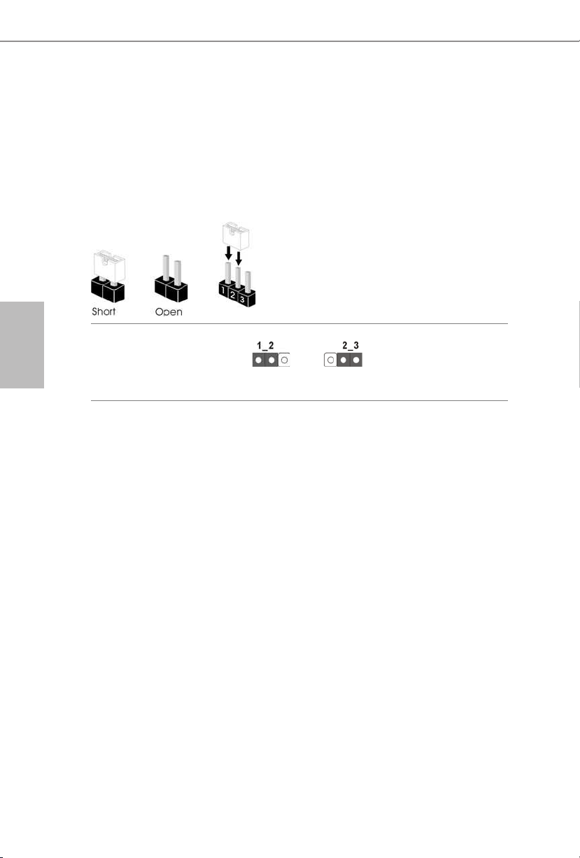
日本語
1.3 ジャンパー設定
このイラストは、ジャンパーの設定方法を示しています。ジャンパーキャップがピ
ンに被さっていると、ジャンパーは「ショート」です。ジャンパーキャップがピンに被
さっていない場合には、ジャンパーは「オープン」です。この図は3 ピンのジャンパー
を表し、ジャンパーキャップがピン1 とピン2 に被さっているとき、これらのピンは
「ショート」です。
CMOS クリアジャンパー
(CLRMOS1)
(p.1、No. 8 参照)
CLRMOS1 を使って CMOS 内のデータをクリアできます。クリアして、デフォルト
設定にシステムパラメーターをリセットするには、コンピューターの電源を切り、
電源から電源コードを抜いてください。15 秒待ってから、ジャンパーキャップを
使って CLRCMOS1 のピン 2 とピン 3 を 5 秒間ショートします。ただし、BIOS を
アップデートした直後に、CMOS をクリアしないでください。BIOS をアップデー
ト後、CMOS をクリアする必要があれば、最初にシステムを起動し、それから
CMOSクリアアクションを行う前にシャットダウンしてください。パスワード、日付、
時間、ユーザーのデフォルトプロファイルは、CMOS の電池を取り外した場合に
のみ、消去されることにご注意ください。
CMOS のクリアデフォルト
98
 Loading...