

Page 1
E3C246D4U2-2L2T
E3C242D4U2-2T
User Manual
Version 1.0
Published November 2018
Copyright©2018 ASRock Rack INC. All rights reserved.
Page 2

Version 1.0
Published November 2018
Copyright©2018 ASRock Rack Inc. All rights reserved.
Copyright Notice:
No part of this documentation may be reproduced, transcribed, transmitted, or
translated in any language, in any form or by any means, except duplication of
documentation by the purchaser for backup purpose, without written consent of
ASRock Rack Inc.
Products and corporate names appearing in this documentation may or may not
be registered trademarks or copyrights of their respective companies, and are used
only for identication or explanation and to the owners’ benet, without intent to
infringe.
Disclaimer:
Specications and information contained in this documentation are furnished
for informational use only and subject to change without notice, and should not
be constructed as a commitment by ASRock Rack. ASRock Rack assumes no
responsibility for any errors or omissions that may appear in this documentation.
With respect to the contents of this documentation, ASRock Rack does not provide
warranty of any kind, either expressed or implied, including but not limited to
the implied warranties or conditions of merchantability or tness for a particular
purpose.
In no event shall ASRock Rack, its directors, ocers, employees, or agents be liable
for any indirect, special, incidental, or consequential damages (including damages
for loss of prots, loss of business, loss of data, interruption of business and the
like), even if ASRock Rack has been advised of the possibility of such damages
arising from any defect or error in the documentation or product.
is device complies with Part 15 of the FCC Rules. Operation is subject to the following
two conditions:
(1) this device may not cause harmful interference, and
(2) this device must accept any interference received, including interference that
may cause undesired operation.
CALIFORNIA, USA ONLY
e Lithium battery adopted on this motherboard contains Perchlorate, a toxic substance
controlled in Perchlorate Best Management Practices (BMP) regulations passed by the
California Legislature. When you discard the Lithium battery in California, USA, please
follow the related regulations in advance.
“Perchlorate Material-special handling may apply, see ww w.dtsc.ca.gov/hazardouswaste/
perchlorate”
ASRock Rack’s Website: www.ASRockRack.com
Page 3

Contact Information
If you need to contact ASRock Rack or want to know more about ASRock Rack,
you’re welcome to visit ASRock Rack ’s website at www.ASRockRack.com; or you
may contact your dealer for further information.
ASRock Rack Incorporation
6F., No.37, Sec. 2, Jhongyang S. Rd., Beitou District,
Taipei City 112, Taiwan (R.O.C.)
e terms HDMI® and HDMI High-Denition Multimedia Interface, and the HDMI
logo are trademarks or registered trademarks of HDMI Licensing LLC in the United
States and other countries.
Page 4

Contents
Chapter 1 Introduction 1
1.1 Package Contents 1
1.2 Specications 2
1.3 Unique Features 6
1.4 Motherboard Layout 7
1.5 Onboard LED Indicators 13
1.6 I/O Panel 15
1.7 Block Diagram 18
Chapter 2 Installation 20
2.1 Screw Holes 20
2.2 Pre-installation Precautions 20
2.3 Installing the CPU 21
2.4 Installing the CPU Fan and Heatsink 23
2.5 Installation of Memory Modules (DIMM) 24
2.6 Expansion Slots (PCI Express Slots) 26
2.7 Jumper Setup 27
2.8 Onboard Headers and Connectors 30
2.9 Dr. Debug (E3C246D4U2-2L2T only) 36
2.10 Unit Identication purpose LED/Switch 37
2.11 Driver Installation Guide 37
2.12 Dua LAN and Teaming Operation Guide 38
2.13 M.2_SSD (NGFF) Module Installation Guide 39
Page 5

Chapter 3 UEFI Setup Utility 41
3.1 Intr o duction 41
3.1.1 UEFI Menu Bar 41
3.1.2 Navigation Keys 42
3.2 Main Screen 43
3.3 Advanced Screen 44
3.3.1 CPU Conguration 45
3.3.2 DRAM Conguration 48
3.3.3 Chipset Conguration 49
3.3.4 Storage Conguration 51
3.3.5 ACPI Conguration 52
3.3.6 USB Conguration 53
3.3.7 Super IO Conguration 54
3.3.8 Serial Port Console Redirection 55
3.3.9 H/W Monitor 59
3.3.10 Runtime Error Logging 61
3.3.11 Intel SPS Conguration 62
3.3.12 Intel(R) Bios Guard Technology 63
3.3.13 Instant Flash 64
3.4 Server Mgmt 65
3.4.1 System Event Log 66
3.4.2 BMC Network Conguration 67
3.5 Security 69
3.5.1 Key Management 70
Page 6

3.6 Boot Screen 74
3.6.1 CSM Parameters 76
3.7 Event Logs 78
3.8 Exit Screen 80
Chapter 4 Software Support 81
4.1 Install Operating System 81
4.2 Support CD Information 81
4.2.1 Running The Support CD 81
4.2.2 Drivers Menu 81
4.2.3 Utilities Menu 81
4.2.4 Contact Information 81
Chapter 5 Troubleshooting 82
5.1 Troubleshooting Procedures 82
5.2 Technical Support Procedures 84
5.3 Returning Merchandise for Service 84
Page 7

E3C246D4U2-2L2T / E3C242D4U2-2T
Chapter 1 Introduction
ank you for purchasing ASRock Rack E3C246D4U2-2L2T / E3C242D4U2-2T
motherboard, a reliable motherboard produced under ASRock Rack’s consistently
stringent quality control. It delivers excellent performance with robust design
conforming to ASRock Rack’s commitment to quality and endurance.
In this manual, chapter 1 and 2 contains introduction of the motherboard and step-
by-step guide to the hardware installation. Chapter 3 and 4 contains the conguration
guide to BIOS setup and information of the Support CD.
Becau se the motherboard specications and the BIOS soware might be updated, the content of thi s manual will be subject to change without notice. In case any modic ations of
this manual occ ur, the updated version will be avail able on ASRock Rack website without
further notice. You may nd the latest memor y and CPU support lists on ASRock Ra ck
website a s well. ASRock Rack’s Website: www.ASRockRack.com
If you require technical support related to this motherboard, please visit our website for
specic information about the model you are using.
http://www.asrockrack.com/support/
1.1 Package Contents
ASRock Rack E3C246D4U2-2L2T / E3C242D4U2-2T Motherboard
•
(mATX Form Factor: 9.6-in x 9.6-in, 24.4 cm x24.4 cm)
Quick Installation Guide
•
1 x SATA3 Cable (60cm)
•
1 x I/O Shield
•
1 x Screw for M.2 Socket
•
If any items are missing or appear damaged, contac t your authoriz ed dealer.
English
Page 8
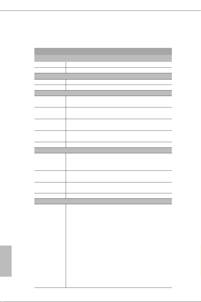
1.2 Specications
E3C246D4U2-2L2T / E3C242D4U2-2T
MB Physical Status
Form Factor mAT X
Dimension 9.6'' x 9.6'' (24.4 cm x24.4 cm)
Processor System
CPU Supports Intel® Xeon® E-2100 Series Processors
Chipset Intel® C246 / Intel® C242
System Memory
Capacity - 4 x 288-pin DDR4 DIMM slots
- Support up to 64GB DDR4 ECC/non-ECC UDIMM
Type - Dual Channel DDR4 memory technology
- Supports DDR4 2666/2400 ECC/non-ECC U DIMM
DIMM Size Per
DIMM
DIMM
Frequency
Vol t age 1.2V
Expansion Slot
PCIe 3.0 x16 Slot 6: Gen3 x16 link, auto switch to x8 link if Slot 4 is
PCIe 3.0 x8 Slot 4: Gen3 x8 link (Physical x8, EE x0/x8 (from CPU),
PCIe 3.0 x4 Slot 5: Gen3 x4 link (Physical x4, EEx4 (from PCH))*
PCIe 3.0 x1 Slot 7: Gen3 x1 link (Physical x1, EEx1 (from PCH))
Storage
SATA
Controller
ECC and non-ECC UDIMM : 64GB, 32GB, 16GB, 8GB, 4GB
- Non-ECC UDIMM: 2666/2400/2133 MHz
- ECC UDIMM: 2666/2400/2133 MHz
occupied (Physical x16, EE x16/x8 (from CPU), shared with
Slot 4)
shared with Slot 6)
*Only supported for E3C246D4U2-2L2T
E3C246D4U2-2L2T:
(1) 8 x SATA3 6Gb/s (SATA0-7, SATA_0 supports SATA
DOM)
(2) 7 x SATA3 6Gb/s (SATA1-7) and 1 x M.2 SSD SATA
connected*
*e M.2 slot (M2_1) is shared w ith the SATA_0 conne ctor. Whe n M2_1 is
populated with a M.2 SATA3 module, the P in 7 of SATA_0 i s disabled.
English
E3C242D4U2-2T:
(1) 6 x SATA3 6Gb/s (SATA0-5, SATA_0 supports SATA
DOM)
(2) 5 x SATA3 6Gb/s (SATA1-5) and 1 x M.2 SSD SATA
connected*
*e M.2 slot (M2_1) is shared w ith the SATA_0 conne ctor. Whe n M2_1 is
2 3
populated with a M.2 SATA3 module, the P in 7 of SATA_0 i s disabled.
Page 9
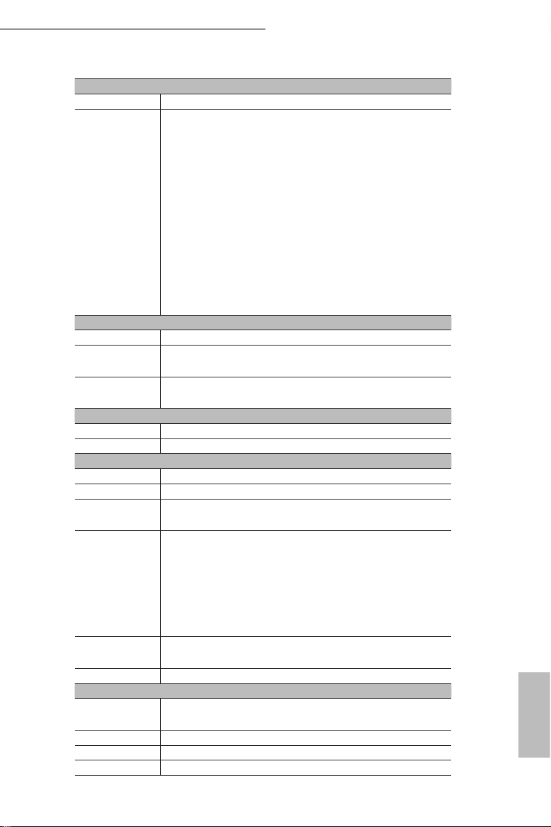
Ethernet
Interface 10000/1000 /100 /10 Mbps
LAN E3C246D4U2-2L2T:
- 2 x RJ45 GLAN by Intel® i210
- 2 x RJ45 10G base-T by Intel® X550-AT2
E3C242D4U2-2T:
- 2 x RJ45 10G base-T by Intel® X550-AT2
- 1 x RJ45 Dedicated IPMI LAN port by RTL8211E
- Supports Wake-On-LAN
- Supports Energy Ecient Ethernet 802.3az
- Supports Dual LAN with Teaming function
- Supports PXE
- LAN1 supports NCSI
Management
BMC Controller ASPEED AST2500
IPMI Dedicated
GLAN
Features - Watch Dog
Graphics
Controller ASPEED AST2500
VRAM DDR4 256MB (128MBx16)
Rear Panel I/O
VGA Port 1 x D-Sub
USB 3.1 Port 2 (Gen2), 2(Ge n1)
HDMI Port E3C246D4U2-2L2T: 1
LAN Port E3C246D4U2-2L2T:
1 x Realtek RTL8211E for dedicated management GLAN
- NMI
E3C242D4U2-2T: N/A
- 4 +1 RJ45 Gigabit Ethernet LAN ports
- LAN Ports with LED (ACT/LINK LED and SPEED LED)
E3C246D4U2-2L2T / E3C242D4U2-2T
E3C242D4U2-2T:
- 2 +1 RJ45 Gigabit Ethernet LAN ports
- LAN Ports with LED (ACT/LINK LED and SPEED LED)
UID Button/
LED
Serial port 1
Internal Connector
Auxiliary Panel
Header
SATA DOM 1 (shared with M.2)
TPM Header 1
IPMB Header 1
1
1 (includes chassis intrusion, location button & LED, and
front LAN LED)
English
Page 10

Front Panel 1 (RST, PWRBTN, HDDLED, PWRLED)
Fan Header 6(1CPU/3Front/2Rear)
ATX Power 1x (24-pin) + 1x (8-pin)
TR1 1
Buzzer 1
USB 3.1 Gen1
Header
USB 2.0 Header 1 (supports 2 USB 2.0 ports)
M.2 (2230/2242/2260/2280, Supports PCIE3.0(X4)/SATA3)
ME/SPS
Recovery
BMC _SMB1 1
PSU_SMB1 1
SGPIO 2
80 Debug Port
LED
ClearCMOS 1 (header and short pin)
OH/FanFail
LED
System BIOS
BI O S Ty p e 256 Mb AMI UEFI Legal BIOS
BIOS Features - Plug and Play (PnP)
Hardware Monitor
Temperature - CPU/PCH/DDR/LAN/Storage Temperature Sensing
Fan - CPU/Rear/Front Fan Tachometer
Vol t age Voltage Monitoring: +12V, +5V, +3.3V, CPU Vcore, DRAM,
Support OS
OS Microso® Windows®
1 (supports 2 USB 3.1 Gen1 ports)
1
E3C246D4U2-2L2T: 1
E3C242D4U2-2T: N/A
1 (Hea der)
- ACPI 2.0 Compliance Wake Up Events
- SMBIOS 2.8.0 Support
- ASRock Rack Instant Flash
- MB/Card side/TR1 Temperature Sensing
- CPU Quiet Fan (Allow Chassis Fan Speed Auto-Adjust by
CPU Temperature)
- CPU/Rear/Front Fan Multi-Speed Control
1.05V_PCH, +BAT, 3VSB, 5VSB
- Server 2016 (64 bit)
Linux®
English
- RedHat Enterprise Linux Server 6.9 (64 bit) / 7.4 (64 bit)
- SUSE Enterprise Linux Server 12 SP1 (64 bit) /
12 SP3 (64 bit)
- Ubuntu 15.10 (64 bit) / 16.04 (64 bit)
*Please refer to our website for the latest OS suppor t list.
4 5
Page 11
E3C246D4U2-2L2T / E3C242D4U2-2T
Environment
Temperature Operation temperature: 10°C ~ 35°C / Non operation
temperature: -40°C ~ 70°C
is motherboard suppor ts Wake from on Board LAN. To use this function, please make sure that
the “Wake on Mag ic Packet from po wer o state” is enabled in D evice Manage r > Intel® Etherne t
Connec tion > Power Management. And the “PCI Devices Power On” is enabled in UEFI SETUP
UTILITY > Advanced > ACPI Cong uration . Aer that, onboard LAN1&2 can wake up S5 under
OS.
If you install Intel® LAN utility or Marvell SATA utility, thi s motherboard may fail Windows® Hardware Quality Lab (WHQL) certication tests. If you install th e drivers only, it will pass the WHQL
tests.
English
Page 12

1.3 Unique Features
ASRock Rack Instant Flash is a BIOS ash utility embedded in Flash ROM. is con-
venient BIOS update tool allows you to update system BIOS without entering operat-
ing systems rst like MS-DOS or Windows®. With this utility, you can press the <F6>
key during the POST or the <F2> key to enter into the BIOS setup menu to access
ASRock Rack Instant Flash. Just launch this tool and save the new BIOS le to your
USB ash drive, oppy disk or hard drive, then you can update your BIOS only in a
few clicks without preparing an additional oppy diskette or other complicated ash
utility. Please be noted that the USB ash drive or hard drive must use FAT32/16/12
le system.
English
6 7
Page 13
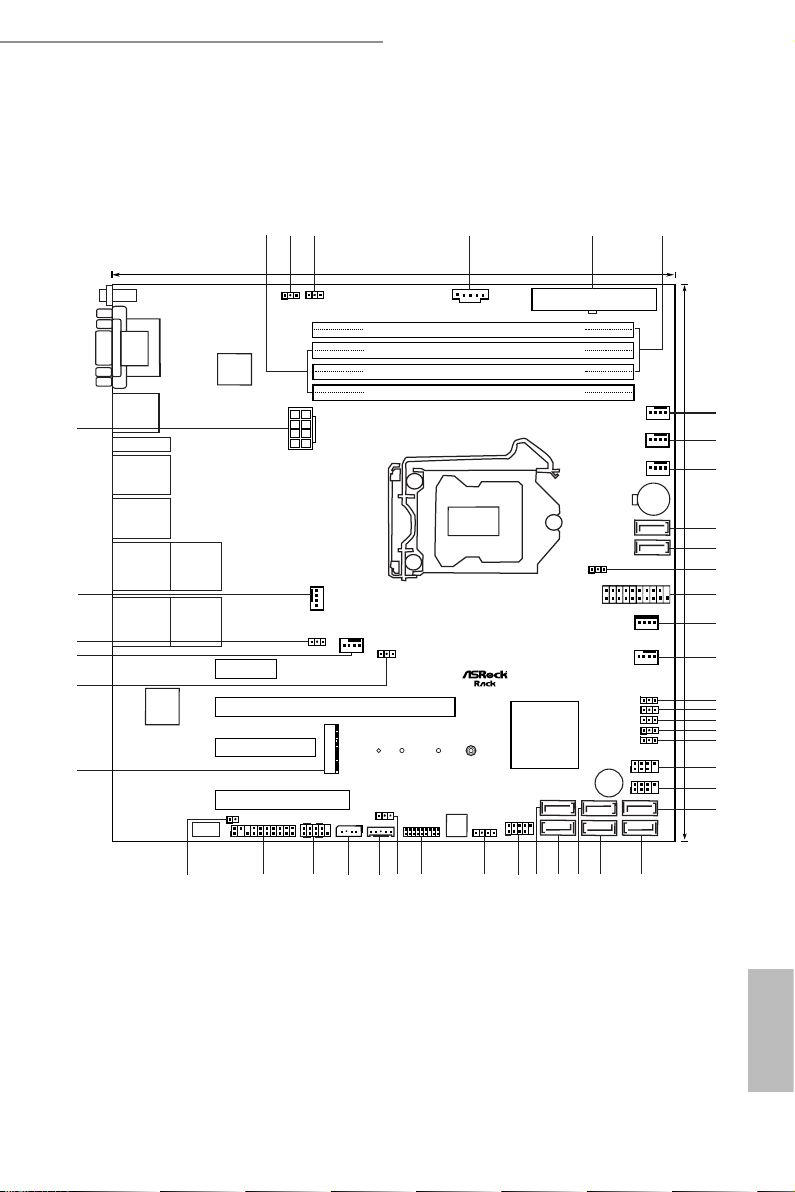
1.4 Motherboard Layout
DDR3_B1 (64 bit, 240-pin module)
DDR3_A1 (64 bit, 240-pin module)
24.4cm (9.6 in)
ATXPWR1
FRNT_FAN1
COM 1
VGA 1
BMC
CPU_FAN1
X550_LAN2
IPMI
LAN
DDR4_B1 (64 bit, 288-pin module)
DDR4_B2 (64 bit, 288-pin module)
DDR3_B1 (64 bit, 240-pin module)
DDR3_A1 (64 bit, 240-pin module)
DDR4_A1(64 bit, 288-pin module)
DDR4_A2 (64 bit, 288-pin module)
FRNT_FAN2
REAR_FAN2
PCIE6
PCIE7
PCIE4
BAT1
1
PSU_SMB1
ATX12V1
1
1
SATA_SGPIO1
1
1
SATA_0
SATA_1
1
USB3_1_2
SATA_PWR1
SATA_2
SATA_3
PANEL1
1
AUX_PANEL1
HDLED RESET
PLED PWRBTN
1
11
SPEAKER1
1
IPMB_1
BMC_SMB_1
1
NMI_BTN1
USB_1_2
1
PEG_CFG1
1
1
TPM1
1
PECI1
UID1
24. 4cm (9. 6 in)
Intel
C246
ME_RECOVERY1
SATAPWR1
BIOS
ROM
1
2
3 5
6
4
7
CHASSIS_ID1
1
T 1
1
Super
I/O
R
NUT30_1
M2_1
NUT42_1 NUT60_1
NUT80_1
REAR_FAN1
8
9
10
11
13
14
38
RoHS
E3C246D4U2-2L2T
39
42
43
1
BMC_DIS1
FRNT_FAN3
SATA_4
SATA_5
CHASSIS_ID0
1
CHASSIS_ID1
1
1
CHASSIS_ID2
1
SEC_OR1
1
SATA_SGPIO2
1
BUZZER1
1
PWM_CFG1
X550_LAN1
12
15
16
17
18
19
20
21
22
23
24
25
26
29
30
31
33
34
35
36
37
40
41
32
USB 3.1 Gen2
T: USB_1
B: USB_2
USB 3.1 Gen1
T: USB_3
B: USB_4
PCIE5
HDMI
SATA_6
SATA_7
28
27
I210_LAN1
I210_LAN2
Dr. Debug
E3C246D4U2-2L2T
E3C246D4U2-2L2T / E3C242D4U2-2T
English
Page 14

English
No. Description
1 2 x 288-pin DDR4 DIMM Slots (DDR4_A2, DDR4_B2, White)
2 Enable/Disable BMC Jumper (BMC_DIS1)
3 ME Recovery Jumper (ME_RECOVERY1)
4 PSU SMBus (PSU_SMB1)
5 ATX Power Connector (ATXPWR1)
6 2 x 288-pin DDR4 DIMM Slots (DDR4_A1, DDR4_B1, Blue)
7 Front Fan Connector (FRNT_FAN1)
8 CPU Fan Connector (CPU_FAN1)
9 Front Fan Connector (FRNT_FAN2)
10 SATA3 DOM Connector (SATA_0), Red*
11 SATA3 Connector (SATA_1)
12 SATA DOM Power Jumper (SATAPWR1)
13 USB 3.0 Header (USB3_1_2)
14 SATA DOM Power Header (SATA_PWR1)
15 Front Fan Connector (FRNT_FAN3)
16 Chassis ID0 Jumper (CHASSIS_ID0)
17 Chassis ID1 Jumper (CHASSIS _ID1)
18 Chassis ID2 Jumper (CHASSIS_ID2)
19 PCI Express Graphics Conguration Jumper (PEG_CFG1)
20 Security Override Jumper (SEC_OR1)
21 SATA SGPIO Connector (SATA_SGPIO1)
22 SATA SGPIO Connector (SATA_SGPIO2)
23 SATA3 Connector (SATA_2)
24 SATA3 Connector (SATA_3)
25 SATA3 Connector (SATA_5)
26 SATA3 Connector (SATA _4)
27 SATA3 Connector (SATA_7)
28 SATA3 Connector (SATA_6)
29 USB 2.0 Header (USB_1_2)
30 Chassis Speaker Header (SPEAKER1)
31 TPM Header (TPM1)
32 ermal Sensor Header (TR1)
33 BMC SMBus Header (BMC_SMB_1)
8 9
Page 15

E3C246D4U2-2L2T / E3C242D4U2-2T
No. Description
34 Intelligent Platform Management Bus Header (IPMB_1)
35 System Panel Header (PANEL1)
36 Auxiliary Panel Header (AUX_PANEL1)
37 Non Maskable Interrupt Button (NMI_BTN1)
38 M.2 Socket (M2 _1) (Type 2230/2242/2260/2280)*
39 PWM Conguration Header (PWM_CFG1)
40 Rear Fan Connector (R EAR_FAN2)
41 CPU PECI Mode Jumper (PECI1)
42 Rear Fan Connector (R EAR_FAN1)
43 ATX 12V Power Connector (ATX12V1)
*e M.2 slot (M2_1) is shared w ith the SATA_0 conne ctor. Whe n M2_1 is populated with a M.2 SATA3 module, the Pin 7 of SATA_0 is disabled .
English
Page 16
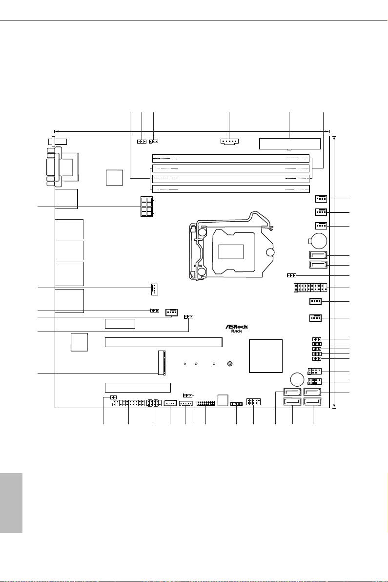
E3C242D 4U2-2T
DDR3_B1 (64 bit, 240-pin module)
DDR3_A1 (64 bit, 240-pin module)
24.4cm (9.6 in)
ATXPWR1
FRNT_FAN1
COM 1
VGA 1
BMC
CPU_FAN1
IPMI
LAN
DDR4_B1 (64 bit, 288-pin module)
DDR4_B2 (64 bit, 288-pin module)
DDR3_B1 (64 bit, 240-pin module)
DDR3_A1 (64 bit, 240-pin module)
DDR4_A1(64 bit, 288-pin module)
DDR4_A2 (64 bit, 288-pin module)
FRNT_FAN2
REAR_FAN2
PCIE6
PCIE7
PCIE4
BAT1
1
PSU_SMB1
ATX12V1
1
1
SATA_SGPIO1
1
1
SATA_0
SATA_1
1
USB3_1_2
SATA_PWR1
SATA_2
SATA_3
PANEL1
1
AUX_PANEL1
HDLED RESET
PLED PWRBTN
1
11
SPEAKER1
1
IPMB_1
BMC_SMB_1
1
NMI_BTN1
PEG_CFG1
1
1
TPM1
1
PECI1
UID1
24. 4cm (9. 6 in)
Intel
C242
ME_RECOVERY1
SATAPWR1
BIOS
ROM
1
2
3 5
6
4
7
CHASSIS_ID1
1
T 1
1
Super
I/O
R
REAR_FAN1
8
9
10
11
13
14
36
E3C242D4U2-2T
37
40
41
1
BMC_DIS1
FRNT_FAN3
SATA_4
SATA_5
CHASSIS_ID0
1
CHASSIS_ID1
1
1
CHASSIS_ID2
1
SEC_OR1
1
SATA_SGPIO2
1
BUZZER1
1
PWM_CFG1
12
15
16
17
18
19
20
21
22
23
2425
26
27
28
29
31
32
33
34
35
38
39
30
USB 3.1 Gen2
T: USB_1
B: USB_2
USB 3.1 Gen1
T: USB_3
B: USB_4
NUT30_1
M2_1
NUT42_1 NUT60_1
NUT80_1
USB_1_2
1
X550_LAN2
X550_LAN1
English
10 11
Page 17

E3C246D4U2-2L2T / E3C242D4U2-2T
No. Description
1 2 x 288-pin DDR4 DIMM Slots (DDR4_A2, DDR4_B2, White)
2 Enable/Disable BMC Jumper (BMC_DIS1)
3 ME Recovery Jumper (ME_RECOVERY1)
4 PSU SMBus (PSU_SMB1)
5 ATX Power Connector (ATXPWR1)
6 2 x 288-pin DDR4 DIMM Slots (DDR4_A1, DDR4_B1, Blue)
7 Front Fan Connector (FRNT_FAN1)
8 CPU Fan Connector (CPU_FAN1)
9 Front Fan Connector (FRNT_FAN2)
10 SATA3 DOM Connector (SATA_0), Red*
11 SATA3 Connector (SATA_1)
12 SATA DOM Power Jumper (SATAPWR1)
13 USB 3.0 Header (USB3_1_2)
14 SATA DOM Power Header (SATA_PWR1)
15 Front Fan Connector (FRNT_FAN3)
16 Chassis ID0 Jumper (CHASSIS_ID0)
17 Chassis ID1 Jumper (CHASSIS _ID1)
18 Chassis ID2 Jumper (CHASSIS_ID2)
19 PCI Express Graphics Conguration Jumper (PEG_CFG1)
20 Security Override Jumper (SEC_OR1)
21 SATA SGPIO Connector (SATA_SGPIO1)
22 SATA SGPIO Connector (SATA_SGPIO2)
23 SATA3 Connector (SATA_2)
24 SATA3 Connector (SATA_3)
25 SATA3 Connector (SATA_5)
26 SATA3 Connector (SATA _4)
27 USB 2.0 Header (USB_1_ 2)
28 Chassis Speaker Header (SPEAKER1)
29 TPM Header (TPM1)
30 ermal Sensor Header (TR1)
31 BMC SMBus Header (BMC_SMB_1)
32 Intelligent Platform Management Bus Header (IPMB_1)
33 System Panel Header (PANEL1)
English
Page 18

No. Description
34 Auxiliary Panel Header (AUX_PANEL1)
35 Non Maskable Interrupt Button (NMI_BTN1)
36 M.2 Socket (M2_1) (Type 2230/2242/2260/2280)*
37 PWM Conguration Header (PWM_CFG1)
38 Rear Fan Connector (REAR_FAN2)
39 CPU PECI Mode Jumper (PECI1)
40 Rear Fan Connector (R EAR_FAN1)
41 ATX 12V Power Connector (ATX12V1)
*e M.2 slot (M2_1) is shared w ith the SATA_0 conne ctor. Whe n M2_1 is populated with a M.2 SATA3 module, the Pin 7 of SATA_0 is disabled .
English
12 13
Page 19
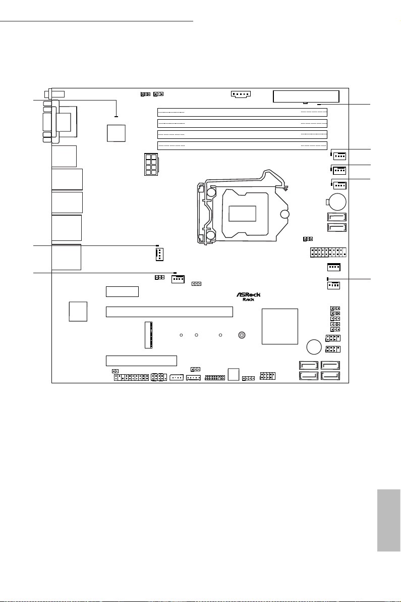
1.5 Onboard LED Indicators
DDR3_B1 (64 bit, 240-pin module)
DDR3_A1 (64 bit, 240-pin module)
ATXPWR1
FRNT_FAN1
COM1
VGA 1
BMC
CPU_FAN1
USB 3.1 Gen2
T: USB_1
B: USB_2
USB 3.1 Gen1
T: USB_3
B: USB_4
IPMI
LAN
DDR4_B1 (64 bit, 288-pin module)
DDR4_B2 (64 bit, 288-pin module)
DDR3_B1 (64 bit, 240-pin module)
DDR3_A1 (64 bit, 240-pin module)
DDR4_A1(64 bit, 288-pin module)
DDR4_A2 (64 bit, 288-pin module)
FRNT_FAN2
REAR_FAN2
PCIE6
PCIE7
PCIE4
1
1
1
SATA_SGPIO1
1
1
1
1
HDLED RESET
PLED PWRBTN
1
11
1
1
1
1
1
1
UID1
Intel
C242
1
1
Super
I/O
NUT30_1
M2_1
NUT42_1 NUT60_1
NUT80_1
REAR_FAN1
RoHS
E3C242D4U2-2T
1
FRNT_FAN3
1
1
11
1
SATA_SGPIO2
1
BUZZER1
1
1
2
3
4
5
6
7
8
X550_LAN2
X550_LAN1
E3C246D4U2-2L2T / E3C242D4U2-2T
English
Page 20

No. Item Status Description
1 SB_PWR1 Green STB PWR ready
2 FRNT_FAN1_L ED1 Amber FRNT_FAN1 failed
3 CPU_FA N1_LED1 Amber CPU_FAN1 failed
4 FRNT_FAN2 _ LED2 Amber FRNT_FAN2 failed
5 FRNT_FAN3_LED3 Amber FRNT_FAN3 failed
6 R EAR_FAN2 _LE D2 Amber REAR_FAN2 failed
7 R EAR_FAN1_LE D1 Amber REAR_FAN1 failed
8 BMC_LE D1 Green BMC heartbeat LED
English
14 15
Page 21

1.6 I/O Panel
E3C246D4U2-2L2T
3
E3C246D4U2-2L2T / E3C242D4U2-2T
9
11
4
5
1
No. Description No. Description
1 UID Switch (UID1) 7 10G LAN RJ-45 Port (X550_LAN1)**
2 VGA Por t ( VGA1) 8 USB 3.1 Gen2 Ports (USB31_1_2)
3 Serial Port (COM1) 9 1G LAN RJ-45 Port (I210_LAN1)***
4 LAN RJ-45 Port (IPMI_LAN)* 10 USB 3.1 Gen1 Ports (USB31_3_4)
5 HDMI Port (HDMI) 11 1G LAN RJ-45 Port (I210_LAN2)***
6 10G LAN RJ-45 Port (X550_LAN2)**
Note: X550_LA N1 / I210_L AN1 supports NC SI.
2
6
7
8
10
E3C242D 4U2-2T
3
1
No. Description No. Description
1 UID Switch (UID1) 5 10G LAN RJ-45 Port (X550_LAN2)**
2 VGA Por t ( VGA1) 6 10G LAN RJ-45 Port (X550_LAN1)**
3 Serial Port (COM1) 7 USB 3.1 Gen2 Ports (USB31_1_2)
4 LAN RJ-45 Port (IPMI_LAN)* 8 USB 3.1 Gen1 Ports (USB31_3_4)
Note: X550_LA N1 supports NCSI.
2
4
5
6
7
8
English
Page 22
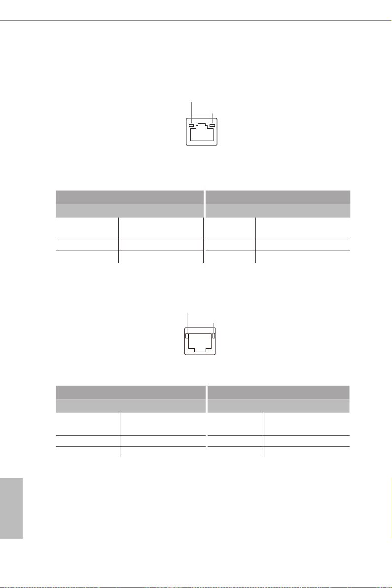
LAN Port LED Indications
*ere are two LED next to the LAN port. Please refer to the table below for the LAN port
LED indications.
ACT/LINK LED
SPEED LED
LAN Por t
Dedicated IPMI LAN Port LED Indications
Activity / Link LED Speed LED
Status Description Status Description
O No Link O 10M bps connection or no
link
Blinking Yellow Data Activity Yel low 100M bps connection
On Link Green 1Gbps connection
**ere are two LEDs on each LAN port. Please refer to the table below for the LAN port
LED indications.
SPEED LE D
ACT/LINK L ED
LAN Port
10G LAN Port LED Indications
Speed LED Activity / Link LED
Status Description Status Description
Yel low 100Mbps connection or
O No Link
no link
Yel low 1Gbps connection Blinking Green Data Activity
Green 10Gbps connection On Link
English
16 17
Page 23
E3C246D4U2-2L2T / E3C242D4U2-2T
***ere are two LEDs on each LAN port. Please refer to the table below for the LAN port
LED indications.
SPEED LED
ACT/LINK LED
LAN Por t
1G LAN Port LED Indications
Speed LED Activity / Link LED
Status Description Status Description
O 10Mbps connection or
no link
Yel low 100Mbps connection Blinking Green Data Activity
Green 1Gbps connection On Link
O No Link
English
Page 24
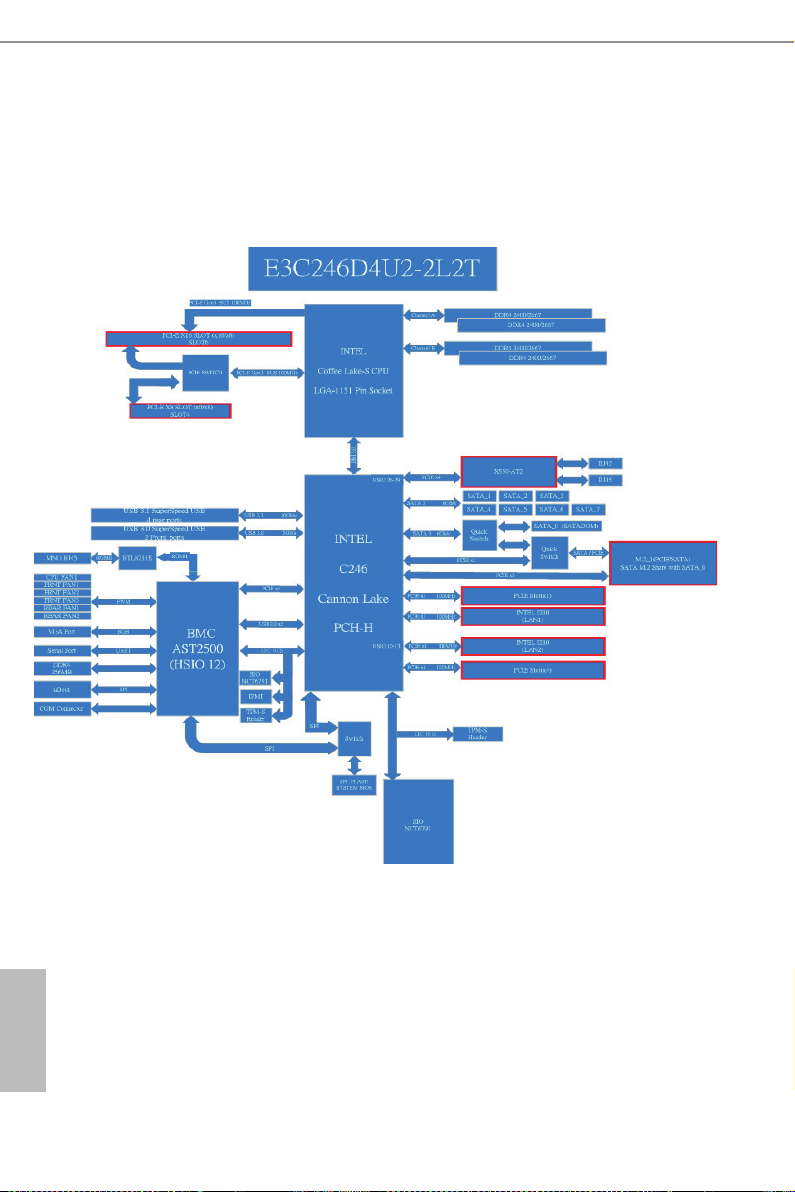
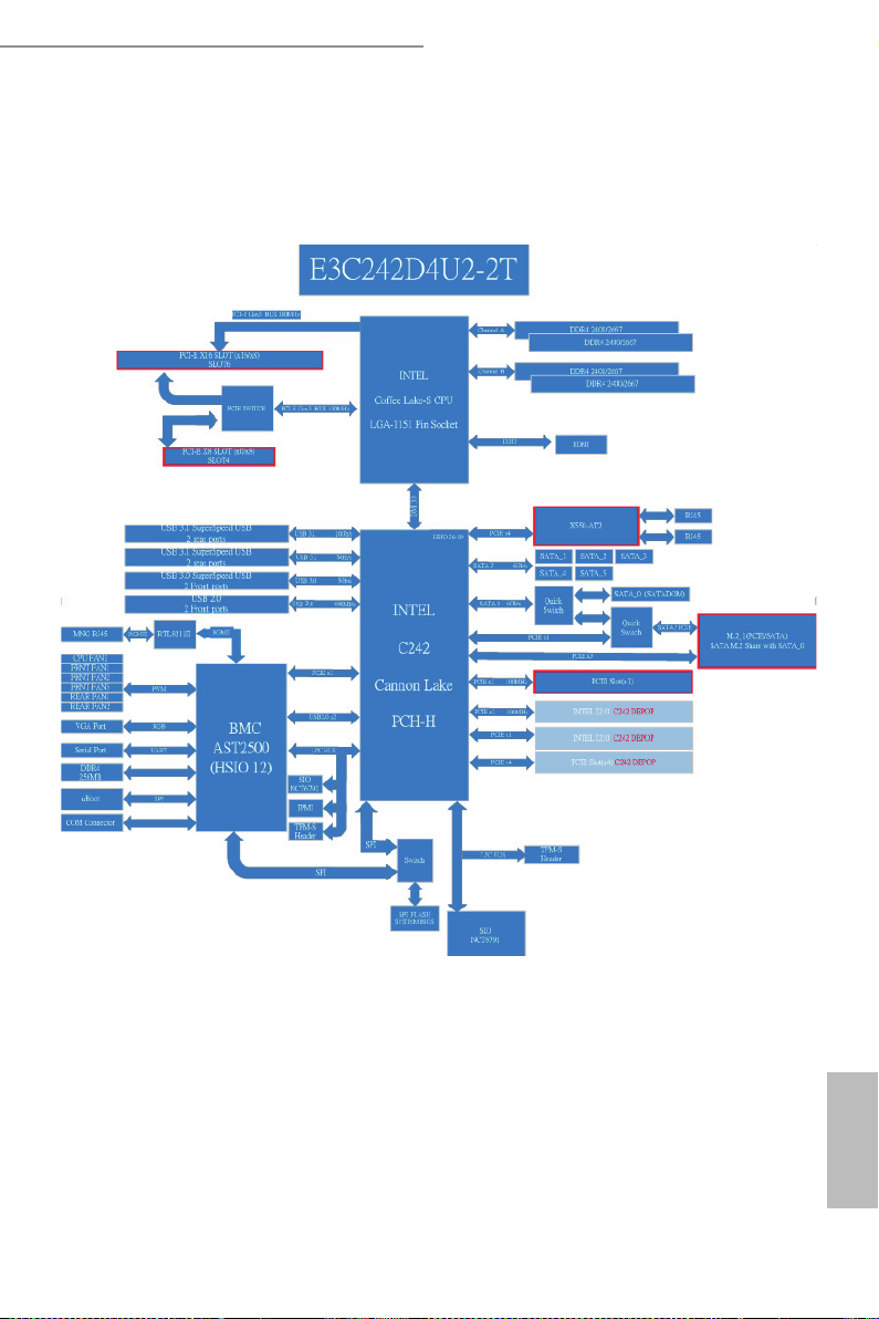
1.7 Block Diagram
English
18 19
Page 25
E3C246D4U2-2L2T / E3C242D4U2-2T
English
Page 26
Chapter 2 Installation
is is a mATX form factor (9.6'' x 9.6'', 24.4 cm x 24.4 cm) motherboard. Before you install
the motherboard, study the conguration of your chassis to ensure that the motherboard
ts into it.
Make sure to unplug the power c ord before installing or re moving the mothe rboard. Failure
to do so may cause physical injurie s to you and d amages to motherboard components.
2.1 Screw Holes
Place screws into the holes indicated by circles to secure the motherboard to the chassis.
Do not over-tighten the screws! Doing so may damage the motherboard.
2.2 Pre-installation Precautions
Take note of the following precautions before you insta ll motherboard components or
change any motherboard settings.
1. Unplug the power cord from the wall socket before touching any components.
2. To avoid damaging the motherboard ’s components due to static electricity, NEVER
place your motherboard directly on the carpet or the like. Also remember to use a
grounded wrist strap or touch a safety grounded object before you handle the compo-
nents.
3. Hold components by the edges and do not touch the ICs.
4. Whenever you uninstall any component, place it on a grounded anti-static pad or in
the bag that comes with the component.
5. When placing screws into the screw holes to secure the motherboard to the chassis,
please do not over-tighten the screws! Doing so may damage the motherboard.
Before you install or remove any component, ensure that the power is switched o or the
power cord is detached f rom the power supply. Failure to d o so may cause severe damage to
the motherboard, peripherals, and/or components.
English
20 21
Page 27
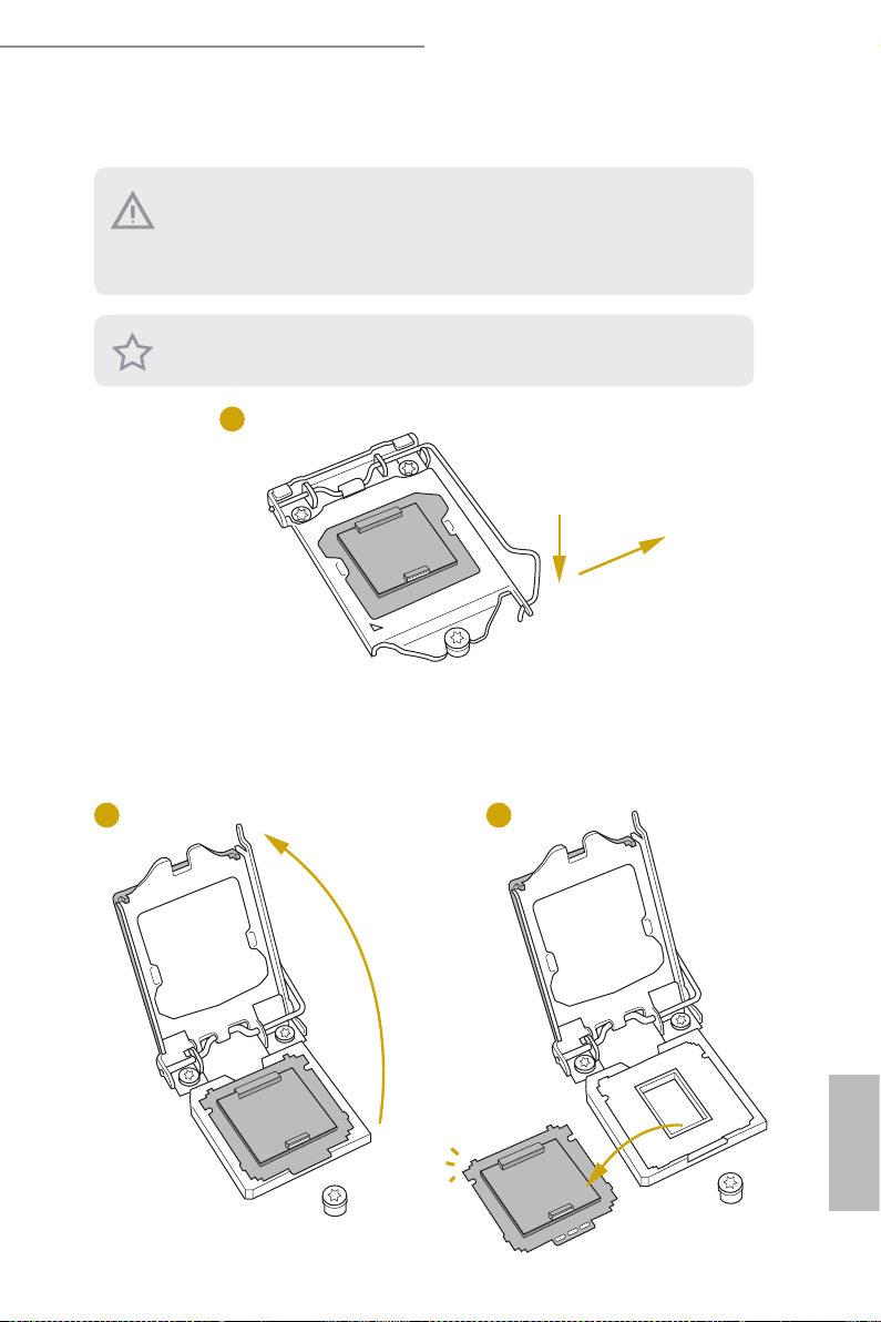
2.3 Installing the CPU
1. Before you in sert the 1151-Pin CPU into the socket, please check if the PnP cap i s on the
socket, if the CPU surface is unclean, or if there are any bent pins in the socket. Do not
force to in sert the CPU into the socket if above situation is found. Otherwise, the CPU
will be seriously damaged.
2. Unplug all power c ables before in stalling the CPU.
Illustrations in this User Manu al are provided for reference only and may slightly dier
from actual product ap pearances.
1
E3C246D4U2-2L2T / E3C242D4U2-2T
A
B
2
3
English
Page 28

4
5
6
English
Please save and replace the cover if the processor i s removed. e cover must be placed if
you wish to return the motherboard for aer service.
22 23
Page 29

E3C246D4U2-2L2T / E3C242D4U2-2T
2.4 Installing the CPU Fan and Heatsink
1 2
N
FA
_
U
P
C
English
Page 30

2.5 Installation of Memory Modules (DIMM)
is motherboard provides four 288-pin DDR4 (Double Data Rate 4) DIMM slots, and
supports Dual Channel Memory Technology.
1. For dual channel cong uration , you always need to in stall identical (the same b rand,
speed , size and chip-type) DDR4 DIMM pairs.
2. It is unable to activate Dual Channel Memor y Technology with only one or three memory
module installed.
3. It is not allowed to install a DDR, DDR2 or DDR3 memory module into a DDR4 sl ot;
otherwise , this motherboard and DIM M may be damaged.
Dual Channel Memory Conguration
Priority DDR4_A1 DDR4_A2 DDR4_B1 DDR4_B2
1 Populated Populated
2 Populated Populated
3 Populated Populated Populated Populated
e DIMM only ts in one correct orientation. It will cause permanent dam age to the
motherboard and the DIMM if you force the DIMM into the slot at incorrect orientation.
English
24 25
Page 31

E3C246D4U2-2L2T / E3C242D4U2-2T
1
2
3
English
e DIMM only ts in one correct orientation. It will cause permanent dam age to the
motherboard and the DIMM if you force the DIMM into the slot at incorrect orientation.
Page 32

2.6 Expansion Slots (PCI Express Slots)
ere are 4 (E3C246D4U2-2L2T) / 3 (E3C242D4U2-2T) PCI Express slots on this
motherboard.
English
PCIE slot:
PCIE4 (PCIe 3.0 x8 slot) is used for PCI Express x8 lane width cards.
PCIE5 (PCIe 3.0 x4 slot) is used for PCI Express x4 lane width cards.
PCIE6 (PCIe 3.0 x16 slot) is used for PCI Express x16 lane width cards.
PCIE7 (PCIe 3.0 x1 slot) is used for PCI Express x1 lane width cards.
*Supports E3C246D4U2-2L2T only.
(E3C246D4U2-2L2T only)
Slot Generation Mechanical Electrical Source
PCIE 7 3.0 x1 x1 PCH
PCIE 6 3.0 x16 x16 CPU
PCIE 5* 3.0 x4 x4 PCH
PCIE 4 3.0 x8 x8 CPU
PCI Express Slot Conguration
PCIE 4 PCIE6
Single PCIE Card x0 x16
Two PCIE Cards x8 x8
Installing an expansion card
Step 1. Before installing an expansion card, please make sure that the power
supply is switched o or the power cord is unplugged. Please read the
documentation of the expansion card and make necessary hardware
settings for the card before you start the installation.
Step 2. Remove the system unit cover (if your motherboard is already installed
in a chassis).
Step 3. Remove the bracket facing the slot that you intend to use. Keep the
screws for later use.
Step 4. Align the card connector with the slot and press rmly until the card is
completely seated on the slot.
Step 5. Fasten the card to the chassis with screws.
Step 6. Replace the system cover.
26 27
Page 33

E3C246D4U2-2L2T / E3C242D4U2-2T
2.7 Jumper Setup
e illustration shows how jumpers are setup. When the jumper cap is placed on
the pins, the jumper is “Short”. If no jumper cap is placed on the pins, the jumper
is “Open”. e illustration shows a 3-pin jumper whose pin1 and pin2 are “Short”
when a jumper cap is placed on these 2 pins.
ME Recover y Jumper
(3-pin ME_RECOVERY1)
CPU PECI Mode Jumper
(3-p in PECI1)
Normal Mode (Default)
CPU PECI connected to
PCH
ME force update
CPU PECI connected to
BMC (Default)
PCI Express Graphics
Conguration Jumper
(3-pin PE G_CF G1)
Security Override Jumper
(3-pin SEC_OR1)
Normal Mode (Default)
Descriptor Security
Override
PCIE6 force @ x8 x8
(CPU Lanes x8 x8)
Not override (Default)
English
Page 34

Chassis ID0 Jumper
(3-pin CHAS SI S _ID 0)
Chassis ID1 Jumper
(3-p in CH ASSI S _ ID1)
Chassis ID2 Jumper
(3-pin CHAS SI S _ID 2)
Chassis ID0 Jumper
(3-pin CHAS SI S _ID 0)
Chassis ID1 Jumper
(3-p in CH ASSI S _ ID1)
Chassis ID2 Jumper
(3-pin CHAS SI S _ID 2)
Board Level SKU (Default) Reserved for system level
use
English
Chassis ID0 Jumper
(3-pin CHAS SI S _ID 0)
Chassis ID1 Jumper
(3-p in CH ASSI S _ ID1)
Chassis ID2 Jumper
(3-pin CHAS SI S _ID 2)
Enable/Disable BMC Jumper
(3-pin BMC_DIS1)
Reserved for system level
use
Reserved for system level
use
Normal Mode (Default)
BMC Enabled
Reserved for system level
use
Reserved for system level
use
BMC Disabled
28 29
Page 35

SATA DOM Power Jumper
(3-pin SATA PWR1)
Consult the documentation that comes with your SATA DOM and check whether or not
Pin 7 requires 5V power supply.
If the connected SATA DOM requires 5V power supply, move the jumper c aps placed on the
SATA DOM Power Jumper (SATAPWR_ SEL) from pins 2-3 (default) to pins 1-2.
If the connected SATA DOM does NOT require 5V powe r supply, connect the SATA DOM
power cable to the SATA DOM power header (SATA_ PWR1) and there is no ne ed to change
the default jumper setting of the SATA DOM Power Jumpe r (pins 2-3).
Warning! Incorrec t setting of the SATA DOM Power Jumper (SATAPWR1) may cause damage to the motherboard or your SATA DOM.
E3C246D4U2-2L2T / E3C242D4U2-2T
SATA DOM (SATA_0)
requires 5V power supply
SATA DOM (SATA_0) does
NOT require 5V power sup-
ply (Default)
English
Page 36

2.8 Onboard Headers and Connectors
Onboard headers and connectors are NOT jumpers. Do NOT place jumper caps over these
heade rs and connectors. Placing jumper caps over the headers and connectors will cause
permanent damage to the motherboard.
System Panel Header
(9-pi n PANEL1)
PWRBTN (Power Switch):
Connec t to the power switch on the chassi s front panel. You may congure the way to tur n
o your system using the power switch.
RESET (Reset Switch):
Connec t to the reset switch on the chassi s front panel. P ress the reset sw itch to restart the
computer if the computer f reezes and fails to perform a normal restar t.
PLED (Syste m Power LED):
Connec t to the power status indicator on the chassis front panel. e LED i s on when the
system is operating. e LED is o when the system is in S4 sleep state or powered o (S5).
HDLED (Ha rd Drive Activity LED):
Connec t to the hard drive ac tivity LED on the chassis front panel. e LED is on when the
hard drive is reading or wr iting data.
e front panel de sign may dier by chassis. A front pane l module mainly consists of power
switch, reset switch , power LED, hard dr ive activity LED, speaker and etc. When connecting your ch assi s front panel module to thi s header, make sure the wire a ssignments and the
pin assignments are matched correctly.
1
PLED+
PLED-
HDLED-
HDLED+
PWRBTN#
GND
GND
RESET#
GND
Co n nec t t h e pow er swit ch,
reset switch and system status
indicator on the chassis to this
he ader a ccording t o t he pi n
assignments. Particularly note
the positive and negative pins
before connecting the cables.
English
30 31
Page 37

E3C246D4U2-2L2T / E3C242D4U2-2T
Auxiliary Panel Header
(18-pin AUX PANEL _1)
A. Front panel SMBus connecting pin (6-1 pin FPSMB)
is hea der allows you to connec t SMBus (System Management Bus) equipment. It can
be used for communication between peripheral equipment in the system, which ha s slower
transmission rates, and power manage ment equipment.
B. Internet status indicator (2-pin LAN1_ LED, LAN2_LED)
ese two 2-pin headers allow you to use the Gigabit internet indicator cable to connect
to the LAN statu s indicator. When this indicator ickers, it mean s that the internet is properly connected.
C. Cha ssis intrusion pin (2-pin CHASSIS)
is hea der is p rovided for host computer chassis with chassis intrusion detection designs.
In addition, it mu st also work with e xternal detection equipment, such as a chassi s intrusion detection sensor or a microswitch. When this function is activated, if any cha ssis
component movement occ urs, the sensor will immediately detect it and send a signal to this
heade r, and the system will then record this chassis intrusion event . e default setting is
set to the CASEOPEN and GND pin; this function i s o.
D. Locator LED (4-pin LOCATOR)
is hea der is for the locator sw itch and L ED on the front pane l.
E. Syste m Fault LED (2-pin LOCATOR)
is hea der is for the Fault LED on the system .
A
B
is header supports multiple
functions on the front panel,
SMB _Aler t
SMB _CLK
1
+5V SB
CAS EOPEN
C
LAN 1_LIN K
+3V SB
GND
SMB _DATA
GND
LOC ATORBTN #
LOC ATORLED 1-
LOC ATORLED 1+
D
including the front panel SMB,
LED _PWR
LED _PWR
LAN 2_LIN K
internet status indicator and
chassis intrusion pin.
GND
E
Sys tem F ault LED+
Sys tem F ault LED-
English
Page 38

Serial ATA3 Connectors
(SATA_0)
(SATA _1)
(SATA_2)
(SATA _3)
(SATA_4)
(SATA_5)
E3C246D4U2-2L2T only:
(SATA_6)
(SATA_7)
SA TA_6
SA TA_7
SA TA _4
SA TA _5
SA TA_0
SA TA_1
ese SATA3 connectors
support SATA data cables for
internal storage devices with
up to 6.0 Gb/s data transfer
rate.
*e M.2 slot (M2_1) is shared w ith
SA TA_2
the SATA_0 connector. When M2_1 is
SA TA_3
populated with a M.2 SATA3 module,
the Pin 7 of SATA_0 is di sabled.
English
Serial ATA3 DOM
Connector
(SATA_0)
SATA DOM Power
Connector
(4-p i n SATA _ PWR1)
USB 2.0 Header
(9-pin USB_1_2)
Chassis Speaker Header
(4-p i n SPEAKER1)
+5V
USB_PWR
1
USB_PWR
DUMMY
1
+5V
GND
-B
-A
SA TA_0
GND
+12V
+B
GND
GND
+A
SPEAKER
DUMMY
DUMMY
The SATA 3 DOM con ne ctor
supports both a SATA DOM
(Disk-On-Module) and a SATA
data cable for internal storage
device.
Please connect a SATA
power cable to the SATA power
connector.
ere is one USB 2.0 header on
this motherboard. Each USB
2.0 header can support two
ports.
Please connect the chassis
speaker to this header.
32 33
Page 39

E3C246D4U2-2L2T / E3C242D4U2-2T
4 3 2 1
48
CPU Fan Connector
(4-pin CPU_FAN1)
Front and Rear Fan
Connectors
(4- pi n FR NT_ FAN1
(4- pi n FR NT_ FAN2)
(4- pi n FR NT_ FAN3)
(4-p i n REAR _ FA N1)
(4- pi n RE AR_FAN2)
ATX Power Connector
(24-p i n ATX PWR1)
4 3 2 1
CPU_FAN_SPEED
FAN _S PEED_CONTROL
FAN_VOLTAGE
FAN_SPEED
FAN_SPEED_CONTROL
1
2
3
FAN_SPEED_CONTROL
4
4 3 2 1
FAN_VOLTAGE
FAN_SPEED
FAN_SPEED_CONTROL
GND
GND
3V
3V
5V
13
3V
-12V
GND
PSON#
GND
GND
FAN_VOLTAGE
GND
GND
FAN_VOLTAGE
FAN_SPEED
GND
PWROK_PS
5VSB
GND
12V
5V
GND
GND
N/A
is motherboard provides
one 4-Pin CPU fan (Quiet
Fan) connectors. If you plan
to connect a 3-Pin CPU fan,
please connect it to Pin 1-3.
*For more details , please refer to the
Cooler QVL list on the ASRock Rack
website.
Please connect fan cables to the
fan connectors and match the
black wire to the ground pin.
All fans support Fan Control.
is motherboard provides a
12V
3V
24-pin ATX power connector.
121
To use a 20-pin ATX power
supply, please plug it along Pin
24
5V5V5V
GND
1 and Pin 13.
ATX 12V Power
Connector
(8-pin ATX12V1)
GND
15
12V
is motherboard provides
one 8-pin ATX 12V power
connector.
English
Page 40

TPM Header
SCLOCK
GND
GND
(17-pi n TP M1)
SMB _D ATA_M AI N
SMB _C LK _MA IN
LAD 2_ L
GND
S_P WR DW N#
LAD 1_ L
GND
is connector supports
Trusted Platform Module
SER IR Q#
(TPM) system, which can
securely store keys, digital
certicates, passwords, and
1
CK_ 33 M_ TPM
LAD 3_ L
+3V
TPM _R ST #
LFR AM E# _L
LAD 0_ L
data. A TPM system also helps
GNDF_C LK RU N#
+3V SB
enhance network security,
protects digital identities, and
ensures platform integrity.
Serial General Purpose
Input/Output Headers
(7-pin SATA _ SGPIO1)
(7-pin SATA _ SGPIO2)
PSU SMBus
(P SU_ SMB1)
Non Maskable Interrupt
Button Header
(N MI_BT N1)
PWM Conguration
Header
(3-p in PW M_CF G1)
1
SDATAOUT
SMBCLK
1
SMBDATA
1
1
SLOAD
GND
GND
ALERT
+3V
GND
CONTROL
SMB_DATA_VSB
SMB_CLK_VSB
The head ers su ppo r t S eria l
Li n k i nter f ace for on b oard
SATA connections.
PSU SMBus monitors the
status of the power supply, fan
and system temperature.
Please con nect a NMI dev ic e
to this header.
is header is used for PWM
congurations.
English
34 35
Page 41

E3C246D4U2-2L2T / E3C242D4U2-2T
GND
BMC_SMB_PRESENT_1_N
IntA_PA_D+
Intelligent Platform
Management Bus Header
(4-pin IPMB_1)
Baseboard Management
Controller SMBus Header
(5-pin BMC_SMB _1)
ermal Sensor Header
(3-pin TR1)
USB 3.1 Gen1 Header
(19-pin USB3_1_2)
1
IntA_PA_D-
IntA_PB_D+
Dummy
No connect
IPMB_SCL
Power
BMC_SMBCLK
TR1 TR1
1
GND
IntA_PA_SSTX+
IntA_PA_SSTX-
GND
IntA_PBA_SSTX+
GND
IntA_PB_D-
IPMB_SDA
GND
BMC_SMBDATA
GND
IntA_PA_SSRX+
IntA_PA_SSRX-
Vbus
IntA_PB_SSRX-
IntA_PB_SSRX+
GND
IntA_PB_SSTX-
This 4-pin connector is used
to provide a cabled base-board
or front panel connection for
value added features and 3rd-
party add-in cards, such as
Emergency Management cards,
that provide management
features using the IPMB.
e header is used for the SM
BUS devices.
Please connect the thermal
sensor cable to either pin 1-2
or pin 2-3 and the other end to
the device which you wish to
monitor its temperature.
Beside s four default USB 3.1
por ts on the I/O panel, there
is one USB 3.1 header on this
mot her board . T his US B 3.1
header can support t wo USB
3.1 ports.
Vbus
English
Page 42

2.9 Dr. Debug
Dr. Debug is used to provide code information, which makes troubleshooting even
easier. Please see the diagrams below for reading the Dr. Debug codes.
Code Description
00 Please check if the CPU is installed correctly and then clear CMOS.
0d
(E3C246D4U2-2L2T only)
Problem related to memory, VGA card or other devices. Please clear
CMOS, re-install the memory and VGA card, and remove other USB, PCI
devices.
English
01 - 54
(except 0d),
5A- 60
55
61 - 91 Chipset initialization error. Please press reset or clear CMOS.
92 - 99
A0 - A7
b0
b4 Problem related to USB devices. Please try removing all USB devices.
b7
d6
Problem related to memory. Please re-install the CPU and memory then
clear CMOS. If the problem still exists, please install only one memor y
module or try using other memory modules.
e Memory could not be detected. Please re-install the memory and CPU.
If the problem still exists, please install only one memory module or try
using other memory modules.
Problem related to PCI-E devices. Please re-install PCI-E devices or try
installing them in other slots. If the problem still exists, please remove all
PCI-E devices or try using another VGA card.
Problem related to IDE or SATA devices. Please re-install IDE and SATA
devices. If the problem still exists, please clear CMOS and try removing all
SATA devices.
Problem related to memory. Please re-install the CPU and memory. If the
problem still exists, please install only one memory module or try using
other memory modules.
Problem related to memory. Please re-install the CPU and memory then
clear CMOS. If the problem still exists, please install only one memor y
module or try using other memory modules.
e VGA could not be recognized. Please clear CMOS and try re-installing
the VGA card. If the problem still exists, please try installing the VGA card
in other slots or use other VGA cards.
d7
d8 Invalid Password.
FF Please check if the CPU is installed correctly and then clear CMOS.
e Keyboard and mouse could not be recognized. Please try re-installing
the keyboard and mouse.
36 37
Page 43

E3C246D4U2-2L2T / E3C242D4U2-2T
2.10 Unit Identication purpose LED/Switch
With the UID button, You are able to locate the server you’re working on from behind
a rack of servers.
Unit Identication
purpose LED/Switch
(UID)
When the UID button on the
front or rear panel is pressed,
the front/rear UID blue LED
indicator will be truned on.
Press the UID button again to
turn o the indicator.
2.11 Driver Installation Guide
To install the drivers to your system, please insert the support CD to your optical
drive rst. en, the drivers compatible to your system can be auto-detected and listed
on the support CD driver page. Please follow the order from top to bottom to install
those required drivers. erefore, the drivers you install can work properly.
English
Page 44

2.12 Dua LAN and Teaming Operation Guide
Dual LAN with Teaming enabled on this motherboard allows two single
connections to act as one single connection(s) for twice the transmission
bandwidth, making data transmission more eective and improving the quality of
transmission of distant images. Fault tolerance on the dual LAN network prevents
network downtime by transferring the workload from a failed port to a working
port.
e speed of transmission is subject to the actual network environment or status even with
Teaming enabled.
Before setting up Teaming, please make sure whether your Switch (or Router)
supports Teaming (IEEE 802.3ad Link Aggregation). You can specify a preferred
adapter in Intel PROSet. Under normal conditions, the Primar y adapter handles all
non-TCP/IP trac. e Secondary adapter will receive fallback trac if the primary
fails. If the Preferred Primary adapter fails, but is later restored to an active status,
control is automatically switched back to the Preferred Primary adapter.
Step 1
From Device Manager, open the properties of a team.
Step 2
Click the Settings tab.
Step 3
Click the Modif y Team button.
Step 4
Select the adapter you want to be the primary adapter and click the Set Primary
button.
If you do not specify a preferred primary adapter, the soware will choose an
adapter of the highest capability (model and speed) to act as the default primary. If
a failover occurs, another adapter becomes the primary. e adapter will, however,
rejoin the team as a non-primary.
English
38 39
Page 45

E3C246D4U2-2L2T / E3C242D4U2-2T
2.13 M.2_SSD (NGFF) Module Installation Guide
The M.2, a lso known as the Next Generation Form Factor (NGFF), is a small size and
versatile c ard edge connector t hat aims to replace mPCIe a nd mSATA. The M.2_SSD
(NGFF) Socket 3 can accommodate either a M.2 SATA3 6.0 Gb/s module or a M.2 PCI
Express module up to Gen 3 x4 (32Gb/s).
*e M.2 slot (M2_1) is shared w ith the SATA_0 conne ctor. Whe n M2_1 is populated with a M.2 SATA3 module, the Pin 7 of SATA_0 is disabled .
Installingg the M.2_SSD (NGFF) Module
Step 1
Prepare a M.2_SSD (NGFF) module
and the screw.
4
3
Step 2
Depending on the PCB type and
length of your M.2_SSD (NGFF)
module, nd the corresponding nut
2
1
A
BCD
location to be used.
No. 1 2 3 4
Nut Location A B C D
PCB Length 3cm 4.2cm 6cm 8cm
Module Type Typ e2230 Type 22 42 Typ e2260 Ty pe 228 0
English
Page 46

Step 3
Move the stando based on the
module type and length.
e stando is placed at the nut
A
BCD
location D by default. Skip Step 3
and 4 and go straight to Step 5 if you
are going to use the default nut.
Otherwise, release the stando by
hand.
Step 4
Peel o the yellow protective lm on
the nut to be used. Hand tighten the
A
BCD
stando into the desired nut location
on the motherboard.
Step 5
Align and gently insert the M.2
(NGFF) SSD module into the M.2
ABCD
slot. Please be aware that the M.2
(NGFF) SSD module only ts in one
orientation.
o
ABCD
20
Step 6
Tighten the screw with a screwdriver
to secure the module into place.
NUT1NUT2D
Please do not overtighten the screw
as this might damage the module.
English
For the latest updates of M.2_SSD (NFGG) module support list, please visit our website for
details: http://www.asrockrack.com
40 41
Page 47

E3C246D4U2-2L2T / E3C242D4U2-2T
Chapter 3 UEFI Setup Utility
3.1 Introduction
is section explains how to use the UEFI SETUP UTILITY to con gure your system. e
UEFI chip on the motherboard stores the UEFI SETUP UTILITY. You may run the UEFI
SETUP UTILITY when you start up the computer. Please press <F2> or <Del> during the
Power-On-Self-Test (POST) to enter the UEFI SETUP UTILITY; otherw ise, POST will
continue with its test routines.
If you wish to enter the UEFI SETUP UTILITY a er POST, restart the system by pressing
<Ctrl> + <Alt> + <Delete>, or by pressing the reset button on the system chassis. You may
also restart by turning the system o and then back on.
Becau se the UEFI so ware is constantly being updated , the following UEFI setup screens
and descriptions are for reference purpose only, and they may not ex actly match what you
see on your screen .
3.1.1 UEFI Menu Bar
e top of the screen has a menu bar with the following selections:
Item Description
Main To set up the system time/date information
Advanced To set up the advanced UEFI features
Server Mgmt To manage the server
Security To set up the security features
Boot
Event Logs For event log con guration
Exit To exit the current screen or the UEFI SETUP UTILITY
Use < > key or < > key to choose among the selections on the menu bar, and
then press <Enter> to get into the sub screen.
To set up the default system device to locate and load the
Operating System
English
Page 48

3.1.2 Navigation Keys
Please check the following table for the function description of each navigation key.
Navigation Key(s) Function Description
/ Moves cursor le or right to select Screens
/ Moves cursor up or down to select items
+ / - To change option for the selected items
<Ta b> Switch to next function
<Enter> To bring up the selected screen
<PGUP> Go to the previous page
<PGDN> Go to the next page
<HOME> Go to the top of the screen
<END> Go to the bottom of the screen
<F1> To display the General Help Screen
<F7> Discard changes and exit the UEFI SETUP UTILITY
<F9> Load optimal default values for all the settings
<F10> Save changes and exit the UEFI SETUP UTILITY
<F12> Print screen
<ESC> Jump to the Exit Screen or exit the current screen
English
42 43
Page 49

E3C246D4U2-2L2T / E3C242D4U2-2T
3.2 Main Screen
Once you enter the UEFI SETUP UTILITY, the Main screen will appear and display the
system over view. e Main screen provides system over view information and allows you
to set the system time and date.
Note: e sc reenshots in this use r manual are examples and for refe rences only. e actual images may
slightly vary depending on the mod el and the version you use .
English
Page 50

3.3 Advanced Screen
In this section, you may set the congurations for the following items: CPU Conguration,
DRAM Conguration, Chipset Conguration, Storage Conguration, ACPI Congura-
tion, USB Conguration, Super IO Conguration, Serial Port Console Redirection, H/W
Monitor, Runtime Errpr Logging, Intel SPS Conguration, Intel(R) Bios Guard Technol-
ogy and Instant Flash.
Setting wrong values in this sec tion may cause the system to malfunction.
English
44 45
Page 51

E3C246D4U2-2L2T / E3C242D4U2-2T
3.3.1 CPU Conguration
Software Guard Extensions (SGX)
Use this item to enable or disable So ware Controlled Soware Guard Extensions (SGX).
SGX Launch Control Policy
Soware Guard Extensions (SGX) Launch Control Policy. Options are:
Intel Locked - Select Intel's Launch Enclave.
Unlocked - Enable OS/VMM conguration of Launch Enclave.
Locked - Allow owner to congure Launch Enclave.
Intel Hyper Threading Technology
Intel Hyper reading Technology allows multiple threads to run on each core, so that the
overall performance on threaded soware is improved.
Active Processor Cores
Select the number of cores to enable in each processor package.
CPU C States Support
Enable CPU C States Support for power saving. It is recommended to keep C3, C6
and C7 all enabled for better power saving.
Enhanced Halt State (C1E)
Enable Enhanced Halt State (C1E) for lower power consumption.
English
Page 52

CPU C3 State Support
Enable C3 deep sleep state for lower power consumption.
CPU C6 State Support
Enable C6 deep sleep state for lower power consumption.
CPU C7 State Support
Enable C7 deep sleep state for lower power consumption.
Package C State Support
Enable CPU, PCIe, Memory, Graphics C State Support for power saving.
Intel Virtualization Technology
Intel Vi rtualization Technolog y allows a plat form to run multiple operat ing systems
and applications in independent partitions, so that one computer system can function as
multiple virtual systems.
VT-d
Intel Virtualization Technolog y for Directed I/O helps your virtual mach ine monitor
better utilize hardware by improving application compatibility and reliability, and provid
additional levels of manageabilit y, security, isolation, and I/O performance.
Hardware Prefetcher
Automatically prefetch data and code for the processor. Enable for better performance.
Adjacent Cache Line Prefetch
Automatically prefetch the subsequent cache line while retrieving the currently requested
cache line. Enable for better performance.
CPU AES
Use this to enable or disable CPU Advanced Encr yption Standard instructions.
Intel SpeedStep Technology
Intel SpeedStep technology is Intel’s new power saving technology. Processors can switch
between multiple frequencies and voltage points to enable power saving. e default value
is [Enabled]. Conguration options: [Enabled] and [Disabled]. is item will be hidden if
English
the current CPU does not support Intel SpeedStep technology.
Please note that enabling this function may reduce CPU voltage and lea d to system stability
or compatibility issues with some power supplies. Ple ase set this item to [Disabled] if above
issues occur.
46 47
Page 53

E3C246D4U2-2L2T / E3C242D4U2-2T
Intel Turbo Boost Technology
Use this item to enable or disable Intel Turbo Boost Mode Technology. Turbo Boost Mode
allows processor cores to run faster than marked frequency in specic conditions. e de-
fault value is [Enabled].
Enable Intel TXT Support
Enables Intel Trusted Execution Technology Conguration.
CPU Thermal Throttling
Enable CPU internal thermal control mechanisms to keep the CPU from overheating.
English
Page 54

3.3.2 DRAM Conguration
DRAM Frequency
If [Auto] is selected, the motherboard will detect the memory modu le(s) inserted and
assign the appropriate frequency automatically.
English
48 49
Page 55

E3C246D4U2-2L2T / E3C242D4U2-2T
3.3.3 Chipset Conguration
Primary Graphics Adapter
If PCI Express graphics card is installed on the motherboard, you may use this option to
select PCI Express or Onboard as the primary graphics adapter.
Onboard VGA
Use this to enable or disable the Onboard VGA function. e default value is [Auto].
Onboard LAN1 and LAN2
is allows you to enable or disable the Onboard LAN 1 and LAN2 feature.
Above 4G Decoding
Enable or disable 64bit capable Devices to be decoded in Above 4G Address Space (only if
the system supports 64 bit PCI decoding).
PCIE6 Link Width
is allows you to select PCIE6 Link Width. e default value is [Auto].
PCIE6 Link Speed
is allows you to select PCIE6 Link Speed. e default value is [Auto].
PCIE6 ASPM Support
is option enables or disables the ASPM support for all CPU downstream devices.
English
Page 56

PCIE7 Link Speed
is allows you to select PCIE7 Link Speed. e default value is [Auto].
PCIE7 ASPM Support
is option enables or disables the ASPM support for all CPU downstream devices.
PCIE4 Link Width
is allows you to select PCIE4 Link Width. e default value is [Auto].
PCIE4 Link Speed
is allows you to select PCIE4 Link Speed. e default value is [Auto].
PCIE4 ASPM Support
is option enables or disables the ASPM support for all CPU downstream devices.
SR-IOV Support
If system has SR-IOV capable PCIe Devices, this option Enables or Disables Single Root IO
Virtualization Support.
Restore AC Power Loss
is allows you to set the power state aer an unexpected AC/power loss. If [Power O]
is selected, the AC/power remains o when the power recovers. If [Power On] is selected,
the AC/power resumes and the system starts to boot up when the power recovers. If [Last
State] is selected, it will recover to the state before AC/power loss.
Restore AC Power Current State
is allows you to restore AC Power Current State.
English
50 51
Page 57

E3C246D4U2-2L2T / E3C242D4U2-2T
3.3.4 Storage Conguration
Hard Disk S.M.A.R.T.
S.M.A.R.T stands for Self-Monitoring, Analysis, and Reporting Technolog y. It is a
monitoring system for computer hard disk drives to detect and report on various
indicators of reliability.
SATA Storage Conguration
Use this item to enable or disable SATA Controllers.
SATA _0/M 2 _1(SATA)
Identify the SATA_0/M2_1(SATA) port is connected to Solid State Drive or Hard Disk
Drive. Press <Ctrl+I> to enter R AID ROM during UEFI POST process.
SATA_1 / SATA_2 / SATA_3 / SATA_4 / SATA_5
Identify the SATA_1 port is connected to Solid State Drive or Hard Disk Drive. Press
<Ctrl+I> to enter RAID ROM during UEFI POST process.
M2 _1(PCI E)
Identify the M2_1(PCIE) port is connected to Solid State Drive or Hard Disk Drive. Press
<Ctrl+I> to enter RAID ROM during UEFI POST process.
English
Page 58

3.3.5 ACPI Conguration
PCIE Devices Power On
Allow the system to be waked up by a PCIE device and enable wake on LAN.
Ring-In Power On
Use this item to enable or disable Ring-In signals to turn on the system from the powerso-
o mode.
RTC Alarm Power On
Allow the system to be waked up by the real time clock alarm. Set it to By OS to let it be
handled by your operating system.
English
52 53
Page 59

E3C246D4U2-2L2T / E3C242D4U2-2T
3.3.6 USB Conguration
Legacy USB Support
En able or disa ble Le g acy OS S upp ort for USB 2 . 0 devic e s. If yo u enc ount er USB
compatibility issues it is recommended to disable legacy USB support.
Select UEFI Setup Only to support USB devices under the UEFI setup and Windows/Linux
operating systems only.
English
Page 60

3.3.7 Super IO Conguration
Serial Port 1 Conguration
Use this item to set parameters of COM1.
Serial Port
Use this item to enable or disable the serial port (COM).
Change Settings
Use this item to select an optimal setting for Super IO device.
SOL Port Conguration
Use this item to set parameters of SOL.
SOL Port Conguration
Use this item to enable or disable the SOL port.
SOL Port Address
Use this item to select an optimal setting for Super IO device.
English
54 55
Page 61

E3C246D4U2-2L2T / E3C242D4U2-2T
3.3.8 Serial Port Console Redirection
COM1
Console Redirection
Use this option to enable or disable Console Redirection. If this item is set to Enabled, you
can select a COM Port to be used for Console Redirection.
Console Redirection Settings
Use this option to congure Console Redirection Settings, and specify how your computer
and the host computer to which you are connected exchange information.
Terminal Type
Use this item to select the preferred terminal emulation type for out-of-band management.
It is recommended to select [VT-UTF8].
Option Description
VT10 0 ASCII character set
VT10 0+ Extended VT100 that supports color and function keys
VT-U TF8 UTF8 encoding is used to map Unicode chars onto 1 or more bytes
ANSI Extended ASCII character set
English
Page 62

English
Bits Per Second
Use this item to select the serial por t transmission speed. The speed used in the host
computer and the client computer must be the same. Long or noisy lines may require lower
transmission speed. e options include [9600], [19200], [38400], [57600] and [115200].
Data Bits
Use this item to set the data transmission size. e options include [7] and [8] (Bits).
Parity
Use this item to select the parity bit. e options include [None], [Even], [Odd], [Mark] and
[Space]. A parity bit can be sent with the data bits to detect some transmission errors.Mark
and Space Parity do not allow for error detection. ey can be used as an additional data
bit.
Even: parity bit is 0 if the num of 1's in the data bits is even.
Odd: parity bit is 0 if num of 1's in the data bits is odd.
Mark: parity bit is always 1.
Space: Parity bit is always 0.
Stop Bits
e item indicates the end of a serial data packet. e standard setting is [1] Stop Bit. Select
[2] Stop Bits for slower devices.
Flow Control
Use this item to set t he f low control to prevent data loss from buf fer overflow. When
sending data, if the receiving buers are full, a "stop" signal can be sent to stop the data
ow. Once the buers are empty, a "start" signal can be sent to restart the ow. Hardware
ow uses two wires to send start/stop signals. e options include [None] and [Hardware
RTS/CTS].
VT-UTF8 Combo Key Support
Use this item to enable or disable the VT-UTF8 Combo Key Support for ANSI/VT100
terminals.
Recorder Mode
Use this item to enable or disable Recorder Mode to capture terminal data and send it as
text messages.
Resolution 100x31
Use this item to enable or disable extended terminal resolution support.
Legacy OS Redirection Resolution
Use this item to select the number of rows and columns used in legacy OS redirection.
Putty Keypad
Use this item to select Function Key and Keypad on Putty.
56 57
Page 63

E3C246D4U2-2L2T / E3C242D4U2-2T
Legacy Console Redirection
Legacy Console Redirection Settings
Use this option to congure Legacy Console Redirection Settings, and specify how your
computer and the host computer to which you are connected exchange information.
Redirection COM Port
Select a COM port to display redirection of Legacy OS and Legacy OPROM Messages.
Resolution
On Legacy OS, the Number of Rows and Columns supported redirection.
Redirection Aer BIOS POST
If the [LoadBooster] is selected, legacy console redirection is disabled before booting to
legacy OS. If [Always Enabled] is selected, legacy console redirection is enabled for legacy
OS. e default value is [Always Enabled].
Serial Port for Out-of-Band Management/Windows Emergency
Management Services (EMS)
Console Redirection
Use this option to enable or disable Console Redirection. If this item is set to Enabled, you
can select a COM Port to be used for Console Redirection.
Console Redirection Settings
Use this option to congure Console Redirection Settings, and specify how your computer
and the host computer to which you are connected exchange information.
Out-of-Band Mgmt Port
Microso Windows Emergency Management Services (EMS) allows for remote
management of a Windows Ser ver OS through a serial port.
Terminal Type
Use this item to select the preferred terminal emulation type for out-of-band management.
It is recommended to select [VT-UTF8].
Option Description
VT10 0 ASCII character set
VT10 0+ Extended VT100 that supports color and function keys
VT-U TF8 UTF8 encoding is used to map Unicode chars onto 1 or more bytes
ANSI Extended ASCII character set
Bits Per Second
Use this item to select the seria l port t ra nsmission speed. The speed used in the host
computer and the client computer must be the same. Long or noisy lines may require lower
English
Page 64

transmission speed. e options include [9600], [19200], [57600] and [115200].
Flow Control
Use this item to set t he f low control to prevent data loss from buf fer overflow. When
sending data, if the receiving buers are full, a "stop" signal can be sent to stop the data
ow. Once the buers are empty, a "start" signal can be sent to restart the ow. Hardware
ow uses two wires to send start/stop signals. e options include [None], [Hardware RTS/
CTS], and [Soware Xon/Xo].
Data Bits
Parity
Stop Bits
English
58 59
Page 65

E3C246D4U2-2L2T / E3C242D4U2-2T
3.3.9 H/W Monitor
In this section, it allows you to monitor the status of the hardware on your system, includ-
ing the parameters of t he CPU temperature, motherboard temperature, CPU fan speed,
chassis fan speed, and the critical voltage.
Fan Control
If [Auto] is selected, the fan speed will controlled by BMC.
If [Manual] is selected, congure the items below.
CPU_ FAN1
is allows you to set the CPU fan1’s speed. e default value is [Smart Fan].
REAR _FA N 1
is allows you to set the rear fan 1’s speed. e default value is [Smart Fan].
REAR _FA N 2
is allows you to set the rear fan 2’s speed. e default value is [Smart Fan].
FR NT_FAN 1
is allows you to set the front fan 1’s speed. e default value is [Smart Fan].
FR NT_FAN 2
is allows you to set the front fan 2’s speed. e default value is [Smart Fan].
English
Page 66

FR NT_FAN 3
is allows you to set the front fan 3’s speed. e default value is [Smart Fan].
Smart Fan Control
is allows you to set the Smart fan’s level speed.
Smart Fan Duty Control
Smart Fan Duty x (x means 1 to 11 stage)
is allows you to set duty cycle for each stage.
Smart Fan Temp Control
Smart Fan Temp x (x means 1 to 11 stage)
is allows you to set temperature for each stage.
Watch Dog Timer
is allows you to enable or disable the Watch Dog Timer. e default value is [Disabled].
English
60 61
Page 67

E3C246D4U2-2L2T / E3C242D4U2-2T
3.3.10 Runtime Error Logging
WHEA Support
Use this item to enable or disable Windows Hardware Error Architecture.
Runtime Error Logging System Enabling
Use this item to enable or disable System Error feature. When it is set to [Enabled], you can
congure Memory Error and PCIE Error log features.
Memory Error Enabling
Memory enabling and logging setup option.
PCI/PCI Error Enabling
Use this item to enable or disable PCIe Correctable errors.
Corrected Error Enable
Correctable Error reshold (0x01-0xFF) used for sparing, tagging, and leaky bucket.
Uncorrected Error Enable
Use this item to enable or disable Uncorrectable errors.
Fatal Error Enable
Use this item to enable or disable Fatal errors.
English
Page 68

3.3.11 Intel SPS Conguration
SPS sc ree n dis plays th e Intel SPS Config u rat ion information, suc h as Operatio nal
Firmware Version and Firmware State.
English
62 63
Page 69

E3C246D4U2-2L2T / E3C242D4U2-2T
3.3.12 Intel(R) Bios Guard Technology
Intel Bios Guard Support
Use this item to enable or disable Intel Bios Guard Support.
English
Page 70

3.3.13 Instant Flash
Instant Flash is a UEFI ash utility embedded in Flash ROM. is convenient UEFI
update tool allows you to update system UEFI without entering operating systems
rst like MS-DOS or Windows®. Just save the new UEFI le to your USB ash drive,
oppy disk or hard drive and launch this tool, then you can update your UEFI only
in a few clicks without preparing an additional oppy diskette or other compli-
cated ash utility. Please be noted that the USB ash drive or hard drive must use
FAT32/16/12 le system. If you execute Instant Flash utility, the utility will show the
UEFI les and their respective information. Select the proper UEFI le to update
your UEFI, and reboot your system aer the UEFI update process is completed.
English
64 65
Page 71

E3C246D4U2-2L2T / E3C242D4U2-2T
3.4 Server Mgmt
Wait For BMC
Wait For BMC response for specied time out. In PILOTII, BMC starts at the same time
when BIOS starts during AC power ON. It takes around 30 seconds to initialize Host to
BMC interfaces.
Inventory support
Use this item to execute inventory function for system. It will take more time at system
boot when it is enabled.
English
Page 72

3.4.1 System Event Log
SEL Components
Change this to enable ro disable all features of System Event Logging during boot.
Erase SEL
Use this to choose options for earsing SEL.
When SEL is Full
Use this to choose options for reactions to a full SEL .
Log EFI Status Codes
Use this item to disable the logging of EFI Status Codes or log only error code or only
progress or both.
English
66 67
Page 73

E3C246D4U2-2L2T / E3C242D4U2-2T
3.4.2 BMC Network Conguration
BMC Out of Band Access
Use this item to enable or disable BMC Out of Band Access.
Lan Channel (Failover)
Manual Setting IPMI LAN
If [No] is selected, t he IP address is assigned by DHCP. If you prefer using a static IP
address, toggle to [Yes], and the changes take eect aer the system reboots. e default
value is [No].
Conguration Address Source
Select to congure BMC network parameters statically or dynamically(by BIOS or BMC).
Conguration options: [Static] and [DHCP].
Static: Manually enter the IP Address, Subnet Mask and Gateway Address in the BIOS for
BMC LAN channel conguration.
DHCP: IP address, Subnet Mask and Gateway Address are automatically assigned by the
network 's DHCP server.
When [DHCP] or [Static] is selected , do NOT modify the BMC network settings on the
IPMI web page.
English
Page 74

e default login information for the IPMI web interface is:
Username: admin
Password: admin
For more instructions on how to set up remote control environment and u se the IPMI management platform, please refer to the IPMI Conguration User Guide or go to the Support
website at: http://www.asrockrack.com/support/faq.asp
English
68 69
Page 75

E3C246D4U2-2L2T / E3C242D4U2-2T
3.5 Security
In this section, you may set or change the supervisor/user password for the system. For the
user password, you may also clear it.
Supervisor Password
Set or change the password for the administrator account. Only the administrator
has authority to change the settings in the UEFI Setup Utility. Leave it blank and
press enter to remove the password.
User Password
Set or change the password for the user account. Users are unable to change the
settings in the UEFI Setup Utility. Leave it blank and press enter to remove the
password.
Secure Boot
Use this to enable or disable Secure Boot Control. e default value is [Disabled].
Enable to support Windows Server 2012 R2 or later versions Secure Boot.
Secure Boot Mode
Secure Boot mode options: Standard or Custom. In Custom mode, Secure Boot
Policy variables can be congured by a physically present user without full authen-
tication.
English
Page 76

3.5.1 Key Management
In this section, expert users can modify Secure Boot Policy variables without full authenti-
cation.
Factory Key Provision
Install factory default Secure Boot keys aer the platform reset and while the System
is in Setup mode.
Install Default Secure Boot Keys
Please install default secure boot keys if it’s the rst time you use secure boot.
Clear Secure Boot keys
Force System to Setup Mode - clear all Secure Boot Variables. Change takes eect
aer reboot.
Export Secure Boot variables
Copy NVRAM content of Secure Boot variables to les in a root folder on a le
English
system device.
Enroll E Image
Allow the image to run in Secure Boot mode. Enroll SHA256 Hash certicate of a
PE image into Authorized Signature Database (db).
70 71
Page 77

E3C246D4U2-2L2T / E3C242D4U2-2T
Remove 'UEFI CA' from DB
Device Guard ready system must not list ‘Microso UEFI CA’ Certicate in Autho-
rized Signature database (db).
Restore DB defaults
Restore DB variable to factory defaults.
Platform Key(PK)
Enroll Factory Defaults or load certicates from a le:
1. Public Key Certicate in:
a) EF I_SIGNATUR E _LIST
b) EFI_CERT_X509 (DER)
c) EFI_CERT_RSA2048 (bin)
d) EFI_CERT_SHA256, 384, 512
2. Authenticated UEFI Variable
3. EFI PE/COFF Image(SHA256)
Key Source: Factory, Externa l, Mixed
Key Exchange Keys
Enroll Factory Defaults or load certicates from a le:
1. Public Key Certicate in:
a) EF I_SIGNATUR E _LIST
b) EFI_CERT_X509 (DER encoded)
c) EFI_CERT_RSA2048 (bin)
d) EFI_CERT_SHA256, 384, 512
2. Authenticated UEFI Variable
3. EFI PE/COFF Image(SHA256)
Key Source: Factory, Externa l, Mixed
Authorized Signatures
Enroll Factory Defaults or load certicates from a le:
English
Page 78

1. Public Key Certicate in:
a) EF I_SIGNATUR E _LIST
b) EFI_CERT_X509 (DER encoded)
c) EFI_CERT_RSA2048 (bin)
d) EFI_CERT_SHA256, 384, 512
2. Authenticated UEFI Variable
3. EFI PE/COFF Image(SHA256)
Key Source: Factory, Externa l, Mixed
Forbidden Signatures
Enroll Factory Defaults or load certicates from a le:
1. Public Key Certicate in:
a) EF I_SIGNATUR E _LIST
b) EFI_CERT_X509 (DER encoded)
c) EFI_CERT_RSA2048 (bin)
d) EFI_CERT_SHA256, 384, 512
2. Authenticated UEFI Variable
3. EFI PE/COFF Image(SHA256)
Key Source: Factory, Externa l, Mixed
Authorized TimeStamps
Enroll Factory Defaults or load certicates from a le:
1. Public Key Certicate in:
a) EF I_SIGNATUR E _LIST
b) EFI_CERT_X509 (DER encoded)
c) EFI_CERT_RSA2048 (bin)
English
d) EFI_CERT_SHA256, 384, 512
2. Authenticated UEFI Variable
3. EFI PE/COFF Image(SHA256)
72 73
Page 79

E3C246D4U2-2L2T / E3C242D4U2-2T
Key Source: Factory, Externa l, Mixedt
OsRecovery Signatures
Enroll Factory Defaults or load certicates from a le:
1. Public Key Certicate in:
a) EF I_SIGNATUR E _LIST
b) EFI_CERT_X509 (DER encoded)
c) EFI_CERT_RSA2048 (bin)
d) EFI_CERT_SHA256, 384, 512
2. Authenticated UEFI Variable
3. EFI PE/COFF Image(SHA256)
Key Source: Default, External, Mixed, Test
English
Page 80

3.6 Boot Screen
In this section, it will display the available devices on your system for you to congure the
boot settings and the boot priority.
Boot Option #1
Use this item to set the system boot order.
Boot Option Filter
is option controls Legacy/UEFI ROMs priority.
Boot From Onboard LAN
Use this item to enable or disable the Boot From Onboard LAN feature.
Setup Prompt Timeout
Congure the number of seconds to wait for the UEFI setup utility.
Bootup Num-Lock
If this item is set to [On], it will automatically activate the Numeric Lock function aer
English
boot-up.
Boot Beep
Select whether the Boot Beep should be turned on or o when the system boots up. Please
note that a buzzer is needed.
74 75
Page 81

E3C246D4U2-2L2T / E3C242D4U2-2T
Full Screen Logo
Use this item to enable or disable OEM Logo. e default value is [Enabled].
AddOn ROM Display
Use this option to adjust AddOn ROM Display. If you enable the option “Full Screen Logo”
but you want to see the AddOn ROM information when the system boots, please select
[Enabled]. Conguration options: [Enabled] and [Disabled]. e default value is [Enabled].
English
Page 82

3.6.1 CSM Parameters
CSM
Enable to launch the Compatibility Support Module. Please do not disable unless
you’re running a WHCK test. If you are using Windows Server 2012 R2 or later ver-
sions 64-bit UEFI and all of your devices support UEFI, you may also disable CSM
for faster boot speed.
Launch Other Storage OpROM Policy
Select UEFI only to run those that support UEFI option ROM only. Select Legacy only to
run those that support legacy option ROM only. Select Do not launch to not execute both
legacy and UEFI option ROM.
Launch Video OpROM Policy
Select UEFI only to run those that support UEFI option ROM only. Select Legacy only to
run those that support legacy option ROM only. Select Do not launch to not execute both
legacy and UEFI option ROM.
English
PCIE4 Slot OpROM
To select Slot Storage and Network Option ROM policy. In Auto option, the default is Dis-
abled with NVMe device, but it is Legacy with other devices. (is item can’t select Video
Option ROM policy.)
76 77
Page 83

E3C246D4U2-2L2T / E3C242D4U2-2T
PCIE5 Slot OpROM
To select Slot Storage and Network Option ROM policy. In Auto option, the default is Dis-
abled with NVMe device, but it is Legacy with other devices. (is item can’t select Video
Option ROM policy.)
PCIE6 Slot OpROM
To select Slot Storage and Network Option ROM policy. In Auto option, the default is Dis-
abled with NVMe device, but it is Legacy with other devices. (is item can’t select Video
Option ROM policy.)
M2_1 Slot OpROM
To select Slot Storage and Network Option ROM policy. In Auto option, the default is Dis-
abled with NVMe device, but it is Legacy with other devices. (is item can’t select Video
Option ROM policy.)
English
Page 84

English
3.7 Event Logs
Change Smbios Event Log Settings
is allows you to congure the Smbios Event Log Settings.
When entering the item, you will see the followings:
Smbios Event Log
Use this item to enable or disable all features of the SMBIOS Event Logging during system
boot.
Erase Event Log
The options include [No], [Yes, Next reset] and [Yes, Ever y reset]. If Yes is selected, all
logged events will be erased.
When Log is Full
Use this item to choose options for reactions to a fu ll Smbios Event Log. The options
include [Do Nothing] and [Erase Immediately].
Log System Boot Event
Choose option to enable/disable logging of System boot event.
MECI (Multiple Event Count Increment)
Use this item to enter the increment value for the multiple event counter. e valid range is
from 1 to 255.
METW (Multiple Event Time Window)
Use this item to specify the number of minutes which must pass between duplicate log
78 79
Page 85

E3C246D4U2-2L2T / E3C242D4U2-2T
entries which utilize a multiple-event counter. e value ranges from 0 to 99 minutes.
View Smbios Event Log
Press <Enter> to view the Smbios Event Log records.
All values changed here do not take eect until computer is restar ted.
English
Page 86

3.8 Exit Screen
Save Changes and Exit
When you select this option, the following message “Save conguration changes and exit
setup?” will pop-out. Press <F10> key or select [Yes] to save the changes and exit the UEFI
SETUP UTILITY.
Discard Changes and Exit
When you select this option, the following message “Discard changes and exit setup?” will
pop-out. Press <ESC> key or select [Yes] to exit the UEFI SETUP UTILITY without saving
any changes.
Discard Changes
When you select this option, the following message “Discard changes?” will pop-out. Press
<F7> key or select [Yes] to discard all changes.
Load UEFI Defaults
Load UEFI default values for a ll the setup questions. F9 key can be used for this operation.
English
80 81
Page 87

E3C246D4U2-2L2T / E3C242D4U2-2T
Chapter 4 Software Support
4.1 Install Operating System
is motherboard supports various Microso® Windows® Server 2016 / Linux compliant.
Because motherboard settings and hardware options vary, use the setup procedures
in this chapter for general reference only. Refer to your OS documentation for more
information.
*Please download the Intel® SATA Floppy Image driver from the ASRock R ack’s website (www.asrockrack.com)
to your USB drive or simply install the SATA driver from the Support CD while installing OS in SATA RAID
mode.
4.2 Support CD Information
e Support CD that came with the motherboard contains necessary drivers and useful
utilities that enhance the motherboard’s features.
4.2.1 Running The Support CD
To be g in usi n g t he su ppor t C D, i n s ert the C D i nto y our CD -ROM driv e. The CD
automatically displays the Main Menu if “AUTORUN” is enabled in your computer. If the
Main Menu does not appear automatically, locate and double click on the le “ASRSetup.
exe” from the root folder in the Support CD to display the menu.
4.2.2 Drivers Menu
The Drivers Menu shows the available device’s drivers if the system detects installed
devices. Please insta ll the necessary drivers to activate the devices.
4.2.3 Utilities Menu
e Utilities Menu shows the application sowares that the motherboard supports. Click
on a specic item then follow the installation wizard to install it.
4.2.4 Contact Information
If you need to contact ASRock Rack or want to know more about ASRock Rack, welcome
to visit ASRock Rack’s website at http://www.ASRockRack.com; or you may contact your
dealer for further information.
English
Page 88

Chapter 5 Troubleshooting
5.1 Troubleshooting Procedures
Follow the procedures below to troubleshoot your system.
Always unplug the power cord before adding, removing or changing any hardware component s. Failure to do so may cause physical injurie s to you and damage s to motherboard
components.
1. Disconnect the power cable and check whether the PWR LED is o.
2. Unplug all cables, connectors and remove all add-on cards from the motherboard.
Make sure that the jumpers are set to default settings.
3. Conrm that there are no short circuits between the motherboard and the chassis.
4. Install a CPU and fan on the motherboard, then connect the chassis speaker and power
LED.
If there is no power...
1. Conrm that there are no short circuits between the motherboard and the chassis.
2. Make sure that the jumpers are set to default settings.
3. Check the settings of the 115V/230V switch on the power supply.
4. Verify if the battery on the motherboard provides ~3VDC. Install a new batter y if it
does not.
If there is no video...
1. Try replugging the monitor cables and power cord.
2. Check for memory errors.
If there are memory errors...
1. Verify that the DIMM modules are properly seated in the slots.
2. Use recommended DDR4 2666/2400 UDIMMs.
3. If you have installed more than one DIMM modules, they should be identical with the
same brand, speed, size and chip-type.
English
4. Try inserting dierent DIMM modules into dierent slots to identif y fault y ones.
5. Check the settings of the 115V/230V switch on the power supply.
82 83
Page 89

E3C246D4U2-2L2T / E3C242D4U2-2T
Unable to save system setup congurations...
1. Verify if the battery on the motherboard provides ~3VDC. Install a new batter y if it
does not.
2. Conrm whether your power supply provides adaquate and stable power.
Other problems...
1. Try searching keywords related to your problem on ASRock Rack’s FAQ page:
http://www.asrockrack.com/support
English
Page 90

5.2 Technical Support Procedures
If you have tried the troubleshooting procedures mentioned above and the problems
are still u nsolved, please contact ASRock Rack ’s technica l suppor t with the followi ng
information:
1. Your contact information
2. Model name, BIOS version and problem type.
3. System conguration.
4. Problem description.
You may contact ASRock Rack’s technical support at:
http://www.asrockrack.com/support/tsd.asp
5.3 Returning Merchandise for Service
For w arr ant y ser vice, t he receipt or a co py of your i nvoice marked w it h t he d at e of
purchase is required. By calling your vendor or going to our RMA website (http://event.
asrockrack.com/tsd.asp) you may obtain a Returned Merchandise Authorization (RMA)
number.
The R MA number should be displayed on the outside of the shipping car ton which is
mailed prepaid or hand-carried when you return the motherboard to the manufacturer.
Shipping and handling charges will be applied for all orders that must be mailed when
service is complete.
Th is wa rranty does not c over d a mages i ncu rred in shippi ng or from fa i lu re due to
alteration, misuse, abuse or improper maintenance of products.
Contact your distributor rst for any product related problems during the warranty period.
English
84 PB
 Loading...