

ASRock E35LM1 R2.0 Owner's Manual

E35LM1 R2.0
User Manual
Version 1.0
Published October 2012
Copyright©2012 ASRock INC. All rights reserved.
1

Copyright Notice:
No part of this manual may be reproduced, transcribed, transmitted, or translated in
any language, in any form or by any means, except duplication of documentation by
the purchaser for backup purpose, without written consent of ASRock Inc.
Products and corporate names appearing in this manual may or may not be regis-
tered trademarks or copyrights of their respective companies, and are used only for
identication or explanation and to the owners’ benet, without intent to infringe.
Disclaimer:
Specications and information contained in this manual are furnished for informa-
tional use only and subject to change without notice, and should not be constructed
as a commitment by ASRock. ASRock assumes no responsibility for any errors or
omissions that may appear in this manual.
With respect to the contents of this manual, ASRock does not provide warranty of
any kind, either expressed or implied, including but not limited to the implied warran-
ties or conditions of merchantability or tness for a particular purpose.
In no event shall ASRock, its directors, ofcers, employees, or agents be liable for
any indirect, special, incidental, or consequential damages (including damages for
loss of prots, loss of business, loss of data, interruption of business and the like),
even if ASRock has been advised of the possibility of such damages arising from
any defect or error in the manual or product.
This device complies with Part 15 of the FCC Rules. Operation is subject to the fol-
lowing two conditions:
(1) this device may not cause harmful interference, and
(2) this device must accept any interference received, including interference that
may cause undesired operation.
CALIFORNIA, USA ONLY
The Lithium battery adopted on this motherboard contains Perchlorate, a toxic
substance controlled in Perchlorate Best Management Practices (BMP) regulations
passed by the California Legislature. When you discard the Lithium battery in Cali-
fornia, USA, please follow the related regulations in advance.
“Perchlorate Material-special handling may apply, see
www.dtsc.ca.gov/hazardouswaste/perchlorate”
ASRock Website: http://www.asrock.com
2

Contents
1 Introduction ........................................................ 5
1.1 Package Contents ......................................................... 5
1.2 Specications ................................................................. 6
1.3 Unique Features ............................................................ 9
1.4 Motherboard Layout ....................................................... 12
1.5 I/O Panel ...................................................................... 13
2 Installation .......................................................... 14
2.1 Screw Holes ................................................................... 14
2.2 Pre-installation Precautions ......................................... 14
2.3 Installation of Memory Modules (DIMM) ........................ 15
2.4 Expansion Slot (PCI Express Slot) ................................ 16
2.5 ASRock Smart Remote Installation Guide ..................... 17
2.6 Jumpers Setup .......................................................... 19
2.7 Onboard Headers and Connectors ............................ 20
2.8 Serial ATA3 (SATA3) Hard Disks Installation ............. 24
2.9 Hot Plug and Hot Swap Functions for SATA3 HDDs .... 24
2.10 SATA3 HDD Hot Plug Feature and Operation Guide ... 25
2.11 Driver Installation Guide ............................................. 27
2.12 Installing Windows® 8 / 8 64-bit / 7 / 7 64-bit / Vista
VistaTM 64-bit / XP / XP 64-bit Without RAID Functions . 27
2.12.1 Installing Windows® XP / XP 64-bit Without RAID
Functions............................................................ 27
2.12.2 Installing Windows® 8 / 8 64-bit / 7 / 7 64-bit /
VistaTM / VistaTM 64-bit Without RAID Functions . 28
TM
/
3

3 UEFI SETUP UTILITY .......................................... 29
3.1 Introduction .................................................................... 29
3.1.1 UEFI Menu Bar .................................................... 29
3.1.2 Navigation Keys ................................................... 30
3.2 Main Screen ................................................................... 30
3.3 OC Tweaker Screen ...................................................... 31
3.4 Advanced Screen ........................................................... 34
3.4.1 CPU Conguration ............................................... 35
3.4.2 North Bridge Conguration................................... 36
3.4.3 South Bridge Conguration .................................. 37
3.4.4 Storage Conguration .......................................... 38
3.4.5 Super IO Conguration ........................................ 39
3.4.6 ACPI Conguration............................................... 40
3.4.7 USB Conguration ............................................... 42
3.5 Tool ................................................................................ 43
3.6 Hardware Health Event Monitoring Screen ................... 45
3.7 Boot Screen ................................................................... 46
3.8 Security Screen ............................................................. 48
3.9 Exit Screen .................................................................... 49
4 Software Support ............................................... 50
4.1 Install Operating System ................................................ 50
4.2 Support CD Information ................................................. 50
4.2.1 Running Support CD ............................................ 50
4.2.2 Drivers Menu ........................................................ 50
4.2.3 Utilities Menu........................................................ 50
4.2.4 Contact Information .............................................. 50
4
Chapter 1: Introduction
Thank you for purchasing ASRock E35LM1 R2.0 motherboard, a reliable mother-
board produced under ASRock’s consistently stringent quality control. It delivers
excellent performance with robust design conforming to ASRock’s commitment to
quality and endurance.
In this manual, chapter 1 and 2 contain introduction of the motherboard and step-
by-step guide to the hardware installation. Chapter 3 and 4 contain the conguration
guide to BIOS setup and information of the Support CD.
Because the motherboard specications and the BIOS software might be
updated, the content of this manual will be subject to change without no-
tice. In case any modications of this manual occur, the updated version
will be available on ASRock website without further notice. You may nd
the latest VGA cards and CPU support lists on ASRock website as well.
ASRock website http://www.asrock.com
If you require technical support related to this motherboard, please visit
our website for specic information about the model you are using.
www.asrock.com/support/index.asp
1.1 Package Contents
ASRock E35LM1 R2.0 Motherboard (Mini-ITX Form Factor)
ASRock E35LM1 R2.0 Quick Installation Guide
ASRock E35LM1 R2.0 Support CD
2 x Serial ATA (SATA) Data Cables (Optional)
1 x I/O Panel Shield
ASRock Reminds You...
To get better performance in Windows® 8 / 8 64-bit / 7 / 7 64-bit / Vista
VistaTM 64-bit, it is recommended to set the BIOS option in Storage Con-
guration to AHCI mode.
TM
5
/

1.2 Specications
Platform - Mini-ITX Form Factor
CPU - AMD Zacate E-240 APU
- Supports AMD’s Cool ‘n’ QuietTM Technology
- UMI 2.5 GT/s
Chipset - AMD A50M Chipset
Memory - 2 x DDR3 DIMM slots
- Supports DDR3 1333(OC)/1066/800 non-ECC, un-buffered
memory
- Max. capacity of system memory: 16GB (see CAUTION 1)
Expansion Slot - 1 x PCI Express 2.0 x16 slot (PCIE1 @ x4 mode)
Graphics - Integrated AMD Radeon HD 6310 graphics
- DX11 class iGPU, Pixel Shader 5.0
- Max. shared memory 512MB
- Supports D-Sub with max. resolution up to 2560x1600 @
60Hz
Audio - 5.1 CH HD Audio (Realtek ALC662 Audio Codec)
LAN - PCIE x1 Gigabit LAN 10/100/1000 Mb/s
- Realtek RTL8111E
- Supports Wake-On-LAN
- Supports LAN Cable Detection
- Supports Energy Efcient Ethernet 802.3az
- Supports PXE
Rear Panel I/O I/O Panel
- 1 x PS/2 Keyboard/Mouse Port
- 1 x VGA Port
- 4 x Ready-to-Use USB 2.0 Ports
- 1 x RJ-45 LAN Port with LED (ACT/LINK LED and SPEED
LED)
- HD Audio Jack: Line in / Front Speaker / Microphone
SATA3 - 4 x SATA3 6.0 Gb/s connectors, support NCQ, AHCI and
“Hot Plug” functions
Connector - 4 x SATA3 6.0Gb/s connectors
- 1 x CIR header
- 1 x COM port header
- 1 x Chassis Intrusion header
- 1 x CPU Fan connector (3-pin)
- 2 x Chassis Fan connectors (1 x 4-pin, 1 x 3-pin)
- 24 pin ATX power connector
- Front panel audio connector
6
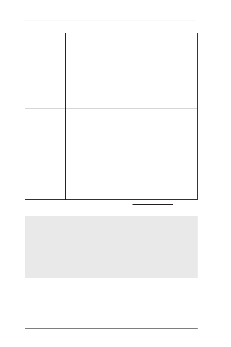
- 2 x USB 2.0 headers (support 4 USB 2.0 ports)
BIOS Feature - 32Mb AMI UEFI Legal BIOS with GUI support
- Supports “Plug and Play”
- ACPI 1.1 Compliance Wake Up Events
- Supports jumperfree
- SMBIOS 2.3.1 Support
- DRAM, FCH, +1V, +1.8V Voltage Multi-adjustment
Support CD - Drivers, Utilities, AntiVirus Software (Trial Version),
CyberLink MediaEspresso 6.5 Trial, ASRock MAGIX
Multimedia Suite - OEM, Google Chrome Browser and
Toolbar
Hardware - CPU Temperature Sensing
Monitor - Chassis Temperature Sensing
- CPU Fan Tachometer
- Chassis Fan Tachometer
- CPU Quiet Fan (Allow Chassis Fan Speed Auto-Adjust by
CPU Temperature)
- CPU/Chassis Fan Multi-Speed Control
- CASE OPEN detection
- Voltage Monitoring: +12V, +5V, +3.3V, CPU Vcore
OS - Microsoft® Windows® 8 / 8 64-bit / 7 / 7 64-bit / Vista
TM
/
VistaTM 64-bit / XP / XP 64-bit compliant (see CAUTION 2)
Certications - FCC, CE, WHQL
- ErP/EuP Ready (ErP/EuP ready power supply is required)
* For detailed product information, please visit our website: http://www.asrock.com
WARNING
Please realize that there is a certain risk involved with overclocking,
including adjusting the setting in the BIOS, applying Untied Overclocking
Technology, or using third-party overclocking tools. Overclocking may
affect your system’s stability, or even cause damage to the components
and devices of your system. It should be done at your own risk and
expense. We are not responsible for possible damage caused by
overclocking.
7

CAUTION!
1. Due to the operating system limitation, the actual memory size
may be less than 4GB for the reservation for system usage un-
der Windows® 8 / 7 / VistaTM / XP. For Windows® OS with 64-bit
CPU, there is no such limitation.
2. ASRock XFast RAM is not supported by Microsoft® Windows®
XP 64-bit.
8

1.3 Unique Features
ASRock Instant Boot
ASRock Instant Boot allows you to turn on your PC in just a few
seconds, provides a much more efcient way to save energy,
time, money, and improves system running speed for your sys-
tem. It leverages the S3 and S4 ACPI features which normally
enable the Sleep/Standby and Hibernation modes in Windows®
to shorten boot up time. By calling S3 and S4 at specic timing
during the shutdown and startup process, Instant Boot allows
you to enter your Windows® desktop in a few seconds.
ASRock Instant Flash
ASRock Instant Flash is a BIOS ash utility embedded in Flash
ROM. This convenient BIOS update tool allows you to update
system BIOS without entering operating systems rst like MS-
DOS or Windows®. With this utility, you can press the <F6> key
during the POST or the <F2> key to enter into the BIOS setup
menu to access ASRock Instant Flash. Just launch this tool and
save the new BIOS le to your USB ash drive, oppy disk or
hard drive, then you can update your BIOS only in a few clicks
without preparing an additional oppy diskette or other compli-
cated ash utility. Please be noted that the USB ash drive or
hard drive must use FAT32/16/12 le system.
ASRock APP Charger
If you d es ir e a fast er, less restricted way of c ha rg in g y ou r
Apple devices, such as iPhone/iPad/iPod Touch, ASRock has
prepared a wonderful solution for you - ASRock APP Charger.
Simply install the APP Charger driver, it makes your iPhone
charge much quickly from your computer and up to 40% faster
than before. ASRock APP Charger allows you to quickly charge
many Apple devices simultaneously and even supports continu-
ous charging when your PC enters into Standby mode (S1),
Suspend to RAM (S3), hibernation mode (S4) or power off (S5).
With APP Charger driver installed, you can easily enjoy the mar-
velous charging experience.
9

ASRock XFast USB
ASRock XFast USB can boost USB stor age device perfor-
mance. The performance may depend on the properties of the
device.
ASRock XFast LAN
ASRock XFast LAN provides a faster internet access, which
includes the benefits listed below. LAN Application Prioritiza-
tion: You can congure your application’s priority ideally and/or
add new programs. Lower Latency in Game: After setting online
game’s priority higher, it can lower the latency in games. Trafc
Shaping: You can watch Youtube HD videos and download si-
multaneously. Real-Time Analysis of Your Data: With the status
window, you can easily recognize which data streams you are
transferring currently.
ASRock XFast RAM
ASRock XFast RAM fully utilizes the memory space that cannot
be used under Windows® OS 32-bit CPU. ASRock XFast RAM
shortens the loading time of previously visited websites, mak-
ing web surng faster than ever. And it also boosts the speed of
Adobe Photoshop 5 times faster. Another advantage of ASRock
XFast RAM is that it reduces the frequency of accessing your
SSDs or HDDs in order to extend their lifespan.
ASRock Crashless BIOS
ASRock Crashless BIOS allows users to update their BIOS
without fear of failing. If power loss occurs during the BIOS up-
date process, ASRock Crashless BIOS will automatically nish
the BIOS update procedure after regaining power. Please note
that BIOS les need to be placed in the root directory of your
USB disk. Only USB2.0 ports support this feature.
ASRock OMG (Online Management Guard)
Administrators are able to establish an internet curfew or restrict
internet access at specied times via OMG. You may schedule
the starting and ending hours of internet access granted to other
users. In order to prevent users from bypassing OMG, guest
accounts without permission to modify the system time are re-
quired.
10

ASRock Internet Flash
ASRock Internet Flash searches for available UEFI firmware
updates from our servers. In other words, the system can auto-
detect the latest UEFI from our servers and ash them without
entering Windows® OS. Please note that you must be running
on a DHCP congured computer in order to enable this function.
ASRock UEFI System Browser
ASRoc k UEFI system b rowse r is a use ful tool inc luded in
graphical UEFI. It can detect the devices and configurations
that users are currently using in their PC. With the UEFI system
browser, you can easily examine the current system congura-
tion in UEFI setup.
ASRock Dehumidier Function
Users may prevent motherboard damages due to dampness by
enabling “Dehumidier Function”. When enabling Dehumidier
Function, the computer will power on automatically to dehumidi-
fy the system after entering S4/S5 state.
ASRock Fast Boot
With ASRock’s exclusive Fast Boot technology, it takes less
than 1.5 seconds to logon to Windows® 8 from a cold boot. No
more waiting! The speedy boot will completely change your user
experience and behavior.
ASRock Restart to UEFI
Windows® 8 brings the ultimate boot up experience. The light-
ning boot up speed makes it hard to access the UEFI setup. AS-
Rock Restart to UEFI technology is designed for those requiring
frequent UEFI access. It allows users to easily enter the UEFI
automatically when turning on the PC next time. Just simply
enable this function; the PC will be assured to access the UEFI
directly in the very beginning.
ASRock Good Night LED
ASRock Good Night LED technology can offer you a better en-
vironment by extinguishing the unessential LED. By enabling
Good Night LED in BIOS, the Power / HDD / LAN LED will be
switched off when system is on. Not only this, Good night LED
will automatically switch off Power and Keyboard LED when the
system enters into Standby / Hibernation mode as well.
11
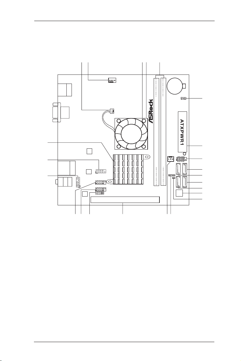
1.4 Motherboard Layout
SPEAKER1
1
PANEL 1
HDLED RESET
PLED PWR BTN
1
CMO S
Bat te ry
32Mb
BIOS
Super
IO
FS B8 00
DDR 3_A 1 ( 64 bit , 240 -pi n m odu le)
FS B8 00
DDR 3_A 2 ( 64 bit , 240 -pi n m odu le)
1
USB6_7
PCI E1
1
USB8_9
CHA_FAN 2
SATA3_1
SATA3_2
SATA3_3 SATA3_4
HD_AUD IO1
1
AUDIO
CODEC
LAN
PHY
1
COM1
CHA_FAN 1
SATA3 6G b/ s
USB 2. 0
T:U SB0
B: USB 1
PS2
Keyb oard/ Mous e
VGA1
USB 2.0
T: USB 4
B: U SB5
Top:
RJ-4 5
Top:
LINE IN
Center:
FRONT
Bottom:
MIC I N
CLRCMOS 1
1
E35 LM 1
Dx 11 Ro HS
CPU_FAN1
1
2
4
3
5
7
6
8
9
10
11
12
13
14
15
16
17
18
1920
23
CIR1
1
21
X
Fas t RAM
DDR 3
CI1
1
22
1 CPU Fan Connector (CPU_FAN1) 12 SATA3 Connector (SATA3_1)
2 Chassis Fan Connector (CHA_FAN1) 13 32Mb SPI Flash
3 CPU Fan 14 Chassis Intrusion Header (CI1)
4 CPU Heatsink 15 Chassis Speaker Header (SPEAKER1)
5 2 x 240-pin DDR3 DIMM Slots 16 Chassis Fan Connector (CHA_FAN2)
(DDR3_A1, DDR3_A2) 17 PCI Express 2.0 x16 Slot (PCIE1)
6 Clear CMOS Jumper (CLRCMOS1) 18 Consumer Infrared Module Header (CIR1)
7 ATX Power Connector (ATXPWR1) 19 USB 2.0 Header (USB8_9)
8 System Panel Header (PANEL1) 20 USB 2.0 Header (USB6_7)
9 SATA3 Connector (SATA3_4) 21 Front Panel Audio Header (HD_AUDIO1)
10 SATA3 Connector (SATA3_2) 22 COM Port Header (COM1)
11 SATA3 Connector (SATA3_3) 23 AMD A50M Chipset
12
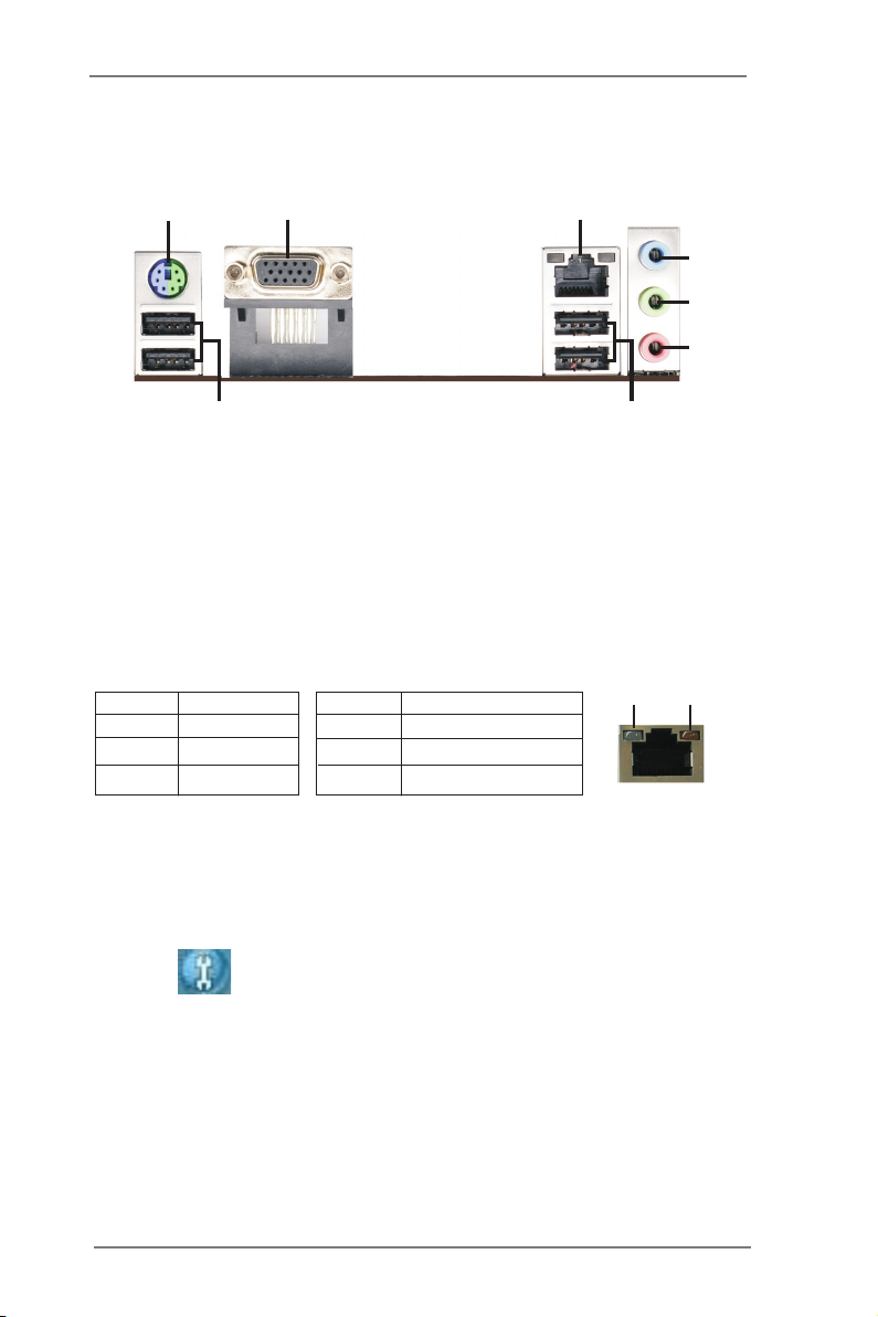
1.5 I/O Panel
1
2
3
4
5
6
8
1 PS/2 Keyboard/Mouse Port (Purple/Green) ** 5 Front Speaker (Lime)
2 VGA Port 6 Microphone (Pink)
* 3 LAN RJ-45 Port 7 USB 2.0 Ports (USB45)
4 Line In (Light Blue) 8 USB 2.0 Ports (USB01)
* There are two LED next to the LAN port. Please refer to the table below for the LAN port LED
indications.
Activity/Link LED SPEED LED
Status Description Status Description
LAN Port LED Indications
7
ACT/LINK
LED
SPEED
LED
Off No Link Off 10Mbps connection
Blinking Data Activity Orange 100Mbps connection
On Link Green 1Gbps connection
LAN Port
** To enable Multi-Streaming function, you need to connect a front panel audio cable to the front
panel audio header. Please refer to below steps for the software setting of Multi-Streaming.
For Windows® XP:
After restarting your computer, you will nd “Mixer” tool on your system. Please select “Mixer
ToolBox” , click “Enable playback multi-streaming”, and click “ok”. Choose “2CH” or
“4CH” and then you are allowed to select “Realtek HDA Primary output” to use Rear Speaker
and Front Speaker, or select “Realtek HDA Audio 2nd output” to use front panel audio. Then
reboot your system.
For Windows® 8 / 7 / VistaTM:
After restarting your computer, please double-click “Realtek HD Audio Manager” on the
system tray. Set “Speaker Conguration” to “Quadraphonic” or “Stereo”. Click “Device
advanced settings”, choose “Make front and rear output devices playbacks two different audio
streams simultaneously”, and click “ok”. Then reboot your system.
13
Chapter 2: Installation
This is a Mini-ITX form factor motherboard. Before you install the motherboard,
study the conguration of your chassis to ensure that the motherboard ts into it.
motherboard. Failure to do so may cause physical injuries to you and
damages to motherboard components.
Make sure to unplug the power cord before installing or removing the
2.1 Screw Holes
Place screws into the holes indicated by circles to secure the motherboard to the
chassis.
Do not over-tighten the screws! Doing so may damage the motherboard.
2.2 Pre-installation Precautions
Take note of the following precautions before you install motherboard components
or change any motherboard settings.
1. Unplug the power cord from the wall socket before touching any component.
2. To avoid damaging the motherboard components due to static electricity,
NEVER place your motherboard directly on the carpet or the like. Also
remember to use a grounded wrist strap or touch a safety grounded object
before you handle components.
3. Hold components by the edges and do not touch the ICs.
4. Whenever you uninstall any component, place it on a grounded antistatic pad or
in the bag that comes with the component.
Before you install or remove any component, ensure that the power is
switched off or the power cord is detached from the power supply.
Failure to do so may cause severe damage to the motherboard, peripherals,
and/or components.
14
2.3 Installation of Memory Modules (DIMM)
E35LM1 R2.0 motherboard provides two 240-pin DDR3 (Double Data Rate 3) DIMM
slots.
It is not allowed to install a DDR or DDR2 memory module into DDR3
slot; otherwise, this motherboard and DIMM may be damaged.
Installing a DIMM
Please make sure to disconnect power supply before adding or
removing DIMMs or the system components.
Step 1. Unlock a DIMM slot by pressing the retaining clips outward.
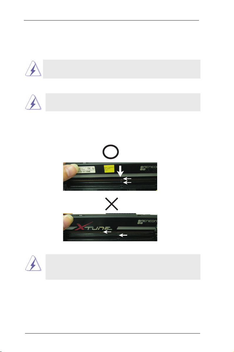
Step 2. Align a DIMM on the slot such that the notch on the DIMM matches the
break on the slot.
notc h
brea k
notc h
brea k
The DIMM only ts in one correct orientation. It will cause permanent
damage to the motherboard and the DIMM if you force the DIMM into
the slot at incorrect orientation.
Step 3. Firmly insert the DIMM into the slot until the retaining clips at both ends
fully snap back in place and the DIMM is properly seated.
15

2.4 Expansion Slot (PCI Express Slot)
There is 1 PCI Express slot on this motherboard.
PCIE slot:
PCIE1 (PCIE x16 slot) is used for PCI Express x4 lane width graphics
cards.
Installing an expansion card
Step 1. Before installing the expansion card, please make sure that the power
supply is switched off or the power cord is unplugged. Please read the
documentation of the expansion card and make necessary hardware
settings for the card before you start the installation.
Step 2. Remove the system unit cover (if your motherboard is already installed
in a chassis).
Step 3. Remove the bracket facing the slot that you intend to use. Keep the
screws for later use.
Step 4. Align the card connector with the slot and press rmly until the card is
completely seated on the slot.
Step 5. Fasten the card to the chassis with screws.
Step 6. Replace the system cover.
16
 Loading...