

Page 1
Copyright Notice:
No part of this installation guide may be reproduced, transcribed, transmitted, or translated in any language, in any form or by any means, except duplication of documentation
by the purchaser for backup purpose, without written consent of ASRock Inc.
Products and corporate names appearing in this guide may or may not be registered
trademarks or copyrights of their respective companies, and are used only for identifi ca-
tion or explanation and to the owners’ benefi t, without intent to infringe.
Disclaimer:
Specifi cations and information contained in this guide are furnished for informational use
only and subject to change without notice, and should not be constructed as a commitment by ASRock. ASRock assumes no responsibility for any errors or omissions that may
appear in this guide.
With respect to the contents of this guide, ASRock does not provide warranty of any kind,
either expressed or implied, including but not limited to the implied warranties or conditions of merchantability or fi tness for a particular purpose. In no event shall ASRock, its
directors, offi cers, employees, or agents be liable for any indirect, special, incidental, or
consequential damages (including damages for loss of profi ts, loss of business, loss of
data, interruption of business and the like), even if ASRock has been advised of the possibility of such damages arising from any defect or error in the guide or product.
This device complies with Part 15 of the FCC Rules. Operation is subject to the following
two conditions:
(1) this device may not cause harmful interference, and
(2) this device must accept any interference received, including interference that
may cause undesired operation.
CALIFORNIA, USA ONLY
The Lithium battery adopted on this motherboard contains Perchlorate, a toxic substance
controlled in Perchlorate Best Management Practices (BMP) regulations passed by the
California Legislature. When you discard the Lithium battery in California, USA, please
follow the related regulations in advance.
“Perchlorate Material-special handling may apply, see
www.dtsc.ca.gov/hazardouswaste/perchlorate”
ASRock Website: http://www.asrock.com
Published October 2012
Copyright©2012 ASRock INC. All rights reserved.
ASRock E35LM1 R2.0 Motherboard
English
1
Page 2
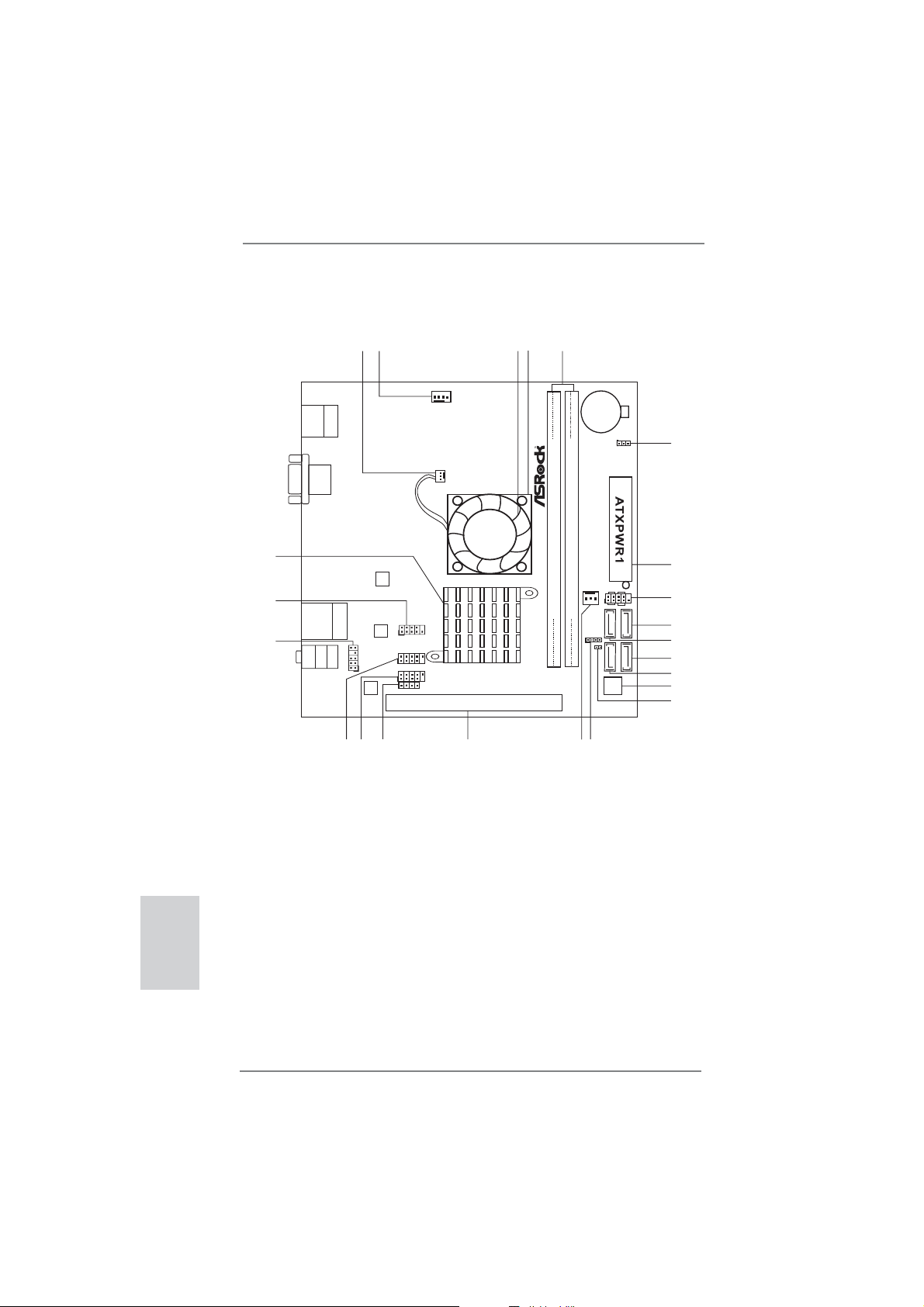
Motherboard Layout
23
22
21
USB2.0
T:USB0
B:USB1
USB 2.0
T:USB4
B: USB5
Bottom:
MIC IN
Keyboard/Mouse
PS2
VGA1
Top:
RJ-45
Top:
LINE IN
Center:
FRONT
1
Dx11 RoHS
SATA3 6Gb/s
HD_AUDIO1
1
AUDIO
CODEC
1920
2
Super
LAN
PHY
18
5
3
4
CHA_FAN1
CPU_FAN1
IO
1
COM1
E35LM1
USB6_7
1
USB8_9
1
CIR1
1
PCIE1
17
Fast RAM
X
DDR3
DDR3_A1 (64bit, 240-pin module)
CMOS
Battery
FSB800
FSB800
CHA_FAN2
DDR3_A2 (64bit, 240-pin module)
SPEAKER1
1
16
15
CLRCMOS1
1
6
7
PANEL1
PLED PWRBTN
1
HDLED RESET
SATA3_2
CI1
1
SATA3_3 SATA3_4
SATA3_1
32Mb
BIOS
8
9
10
11
12
13
14
English
2
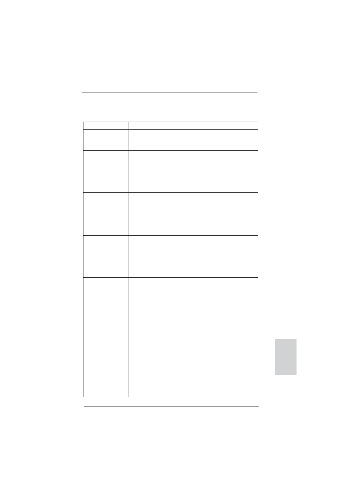
1 CPU Fan Connector (CPU_FAN1) 12 SATA3 Connector (SATA3_1)
2 Chassis Fan Connector (CHA_FAN1) 13 32Mb SPI Flash
3 CPU Fan 14 Chassis Intrusion Header (CI1)
4 CPU Heatsink 15 Chassis Speaker Header (SPEAKER1)
5 2 x 240-pin DDR3 DIMM Slots 16 Chassis Fan Connector (CHA_FAN2)
(DDR3_A1, DDR3_A2) 17 PCI Express 2.0 x16 Slot (PCIE1)
6 Clear CMOS Jumper (CLRCMOS1) 18 Consumer Infrared Module Header (CIR1)
7 ATX Power Connector (ATXPWR1) 19 USB 2.0 Header (USB8_9)
8 System Panel Header (PANEL1) 20 USB 2.0 Header (USB6_7)
9 SATA3 Connector (SATA3_4) 21 Front Panel Audio Header (HD_AUDIO1)
10 SATA3 Connector (SATA3_2) 22 COM Port Header (COM1)
11 SATA3 Connector (SATA3_3) 23 AMD A50M Chipset
ASRock E35LM1 R2.0 Motherboard
Page 3
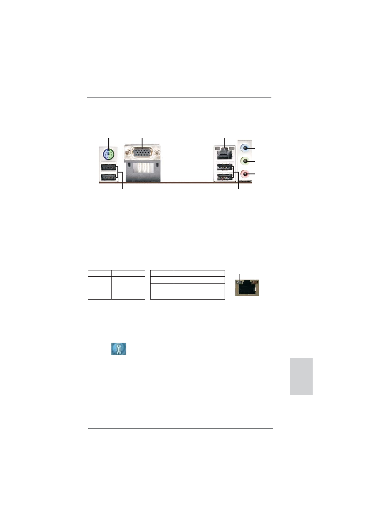
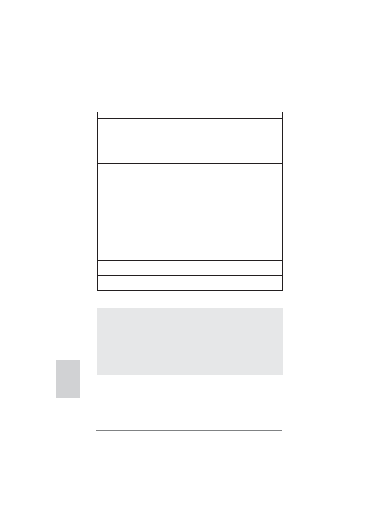
I/O Panel
1
2
3
4
5
6
8
1 PS/2 Keyboard/Mouse Port (Purple/Green) ** 5 Front Speaker (Lime)
2 VGA Port 6 Microphone (Pink)
* 3 LAN RJ-45 Port 7 USB 2.0 Ports (USB45)
4 Line In (Light Blue) 8 USB 2.0 Ports (USB01)
* There are two LED next to the LAN port. Please refer to the table below for the LAN port LED
indications.
Activity/Link LED SPEED LED
Status Description Status Description
LAN Port LED Indications
7
ACT/LINK
LED
SPEED
LED
Off No Link Off 10Mbps connection
Blinking Data Activity Orange 100Mbps connection
On Link Green 1Gbps connection
LAN Port
** To enable Multi-Streaming function, you need to connect a front panel audio cable to the front
panel audio header. Please refer to below steps for the software setting of Multi-Streaming.
For Windows® XP:
After restarting your computer, you will fi nd “Mixer” tool on your system. Please select “Mixer
ToolBox” , click “Enable playback multi-streaming”, and click “ok”. Choose “2CH” or
“4CH” and then you are allowed to select “Realtek HDA Primary output” to use Rear Speaker
and Front Speaker, or select “Realtek HDA Audio 2nd output” to use front panel audio. Then
reboot your system.
For Windows
After restarting your computer, please double-click “Realtek HD Audio Manager” on the
system tray. Set “Speaker Confi guration” to “Quadraphonic” or “Stereo”. Click “Device
advanced settings”, choose “Make front and rear output devices playbacks two different audio
streams simultaneously”, and click “ok”. Then reboot your system.
®
8 / 7 / VistaTM:
ASRock E35LM1 R2.0 Motherboard
English
3
Page 4
1. Introduction
Thank you for purchasing ASRock E35LM1 R2.0 motherboard, a reliable motherboard produced under ASRock’s consistently stringent quality control. It delivers
excellent performance with robust design conforming to ASRock’s commitment to
quality and endurance.
This Quick Installation Guide contains introduction of the motherboard and step-bystep installation guide. More detailed information of the motherboard can be found
in the user manual presented in the Support CD.
Because the motherboard specifi cations and the BIOS software might be
updated, the content of this manual will be subject to change without notice. In case any modifi cations of this manual occur, the updated version
will be available on ASRock website without further notice. You may fi nd
the latest VGA cards and CPU support lists on ASRock website as well.
ASRock website http://www.asrock.com
If you require technical support related to this motherboard, please visit
our website for specifi c information about the model you are using.
www.asrock.com/support/index.asp
1.1 Package Contents
ASRock E35LM1 R2.0 Motherboard (Mini-ITX Form Factor)
ASRock E35LM1 R2.0 Quick Installation Guide
ASRock E35LM1 R2.0 Support CD
2 x Serial ATA (SATA) Data Cables (Optional)
1 x I/O Panel Shield
English
4
ASRock Reminds You...
To get better performance in Windows® 8 / 8 64-bit / 7 / 7 64-bit / Vista
VistaTM 64-bit, it is recommended to set the BIOS option in Storage Confi guration to AHCI mode. For the BIOS setup, please refer to the “User
Manual” in our support CD for details.
TM
ASRock E35LM1 R2.0 Motherboard
/
Page 5
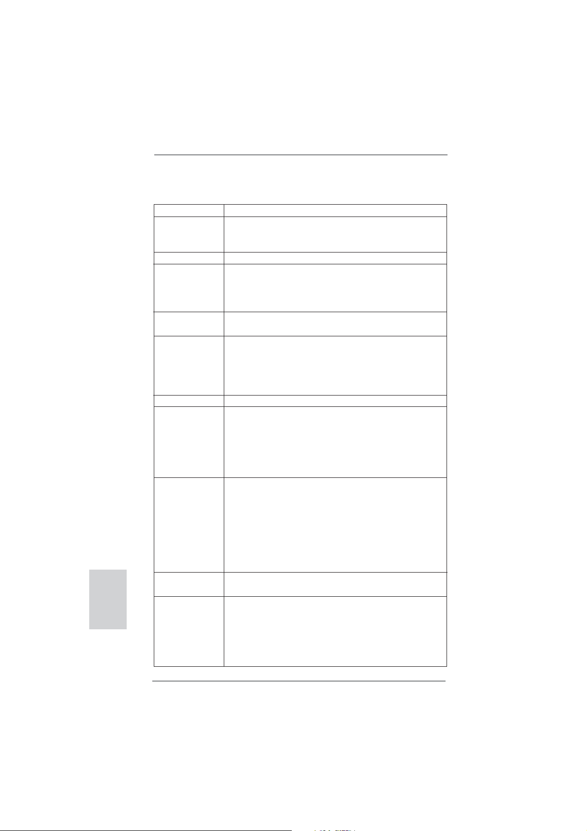
1.2 Specifi cations
Platform - Mini-ITX Form Factor
CPU - AMD Zacate E-240 APU
- Supports AMD’s Cool ‘n’ Quiet
- UMI 2.5 GT/s
Chipset - AMD A50M Chipset
Memory - 2 x DDR3 DIMM slots
- Supports DDR3 1333(OC)/1066/800 non-ECC, un-buffered
memory
- Max. capacity of system memory: 16GB (see CAUTION 1)
Expansion Slot - 1 x PCI Express 2.0 x16 slot (PCIE1 @ x4 mode)
Graphics - Integrated AMD Radeon HD 6310 graphics
- DX11 class iGPU, Pixel Shader 5.0
- Max. shared memory 512MB
- Supports D-Sub with max. resolution up to 2560x1600 @
60Hz
Audio - 5.1 CH HD Audio (Realtek ALC662 Audio Codec)
LAN - PCIE x1 Gigabit LAN 10/100/1000 Mb/s
- Realtek RTL8111E
- Supports Wake-On-LAN
- Supports LAN Cable Detection
- Supports Energy Effi cient Ethernet 802.3az
- Supports PXE
Rear Panel I/O I/O Panel
- 1 x PS/2 Keyboard/Mouse Port
- 1 x VGA Port
- 4 x Ready-to-Use USB 2.0 Ports
- 1 x RJ-45 LAN Port with LED (ACT/LINK LED and SPEED
LED)
- HD Audio Jack: Line in / Front Speaker / Microphone
SATA 3 - 4 x SATA3 6.0 Gb/s connectors, support NCQ, AHCI and
“Hot Plug” functions
Connector - 4 x SATA3 6.0Gb/s connectors
- 1 x CIR header
- 1 x COM port header
- 1 x Chassis Intrusion header
- 1 x CPU Fan connector (3-pin)
- 2 x Chassis Fan connectors (1 x 4-pin, 1 x 3-pin)
- 24 pin ATX power connector
- Front panel audio connector
TM
Technology
English
ASRock E35LM1 R2.0 Motherboard
5
Page 6
- 2 x USB 2.0 headers (support 4 USB 2.0 ports)
BIOS Feature - 32Mb AMI UEFI Legal BIOS with GUI support
- Supports “Plug and Play”
- ACPI 1.1 Compliance Wake Up Events
- Supports jumperfree
- SMBIOS 2.3.1 Support
- DRAM, FCH, +1V, +1.8V Voltage Multi-adjustment
Support CD - Drivers, Utilities, AntiVirus Software (Trial Version),
CyberLink MediaEspresso 6.5 Trial, ASRock MAGIX
Multimedia Suite - OEM, Google Chrome Browser and
Toolbar
Hardware - CPU Temperature Sensing
Monitor - Chassis Temperature Sensing
- CPU Fan Tachometer
- Chassis Fan Tachometer
- CPU Quiet Fan (Allow Chassis Fan Speed Auto-Adjust by
CPU Temperature)
- CPU/Chassis Fan Multi-Speed Control
- CASE OPEN detection
- Voltage Monitoring: +12V, +5V, +3.3V, CPU Vcore
OS - Microsoft
®
Windows® 8 / 8 64-bit / 7 / 7 64-bit / Vista
TM
/
VistaTM 64-bit / XP / XP 64-bit compliant (see CAUTION 2)
Certifi cations - FCC, CE, WHQL
- ErP/EuP Ready (ErP/EuP ready power supply is required)
* For detailed product information, please visit our website: http://www.asrock.com
English
6
WARNING
Please realize that there is a certain risk involved with overclocking,
including adjusting the setting in the BIOS, applying Untied Overclocking
Technology, or using third-party overclocking tools. Overclocking may
affect your system’s stability, or even cause damage to the components
and devices of your system. It should be done at your own risk and
expense. We are not responsible for possible damage caused by
overclocking.
ASRock E35LM1 R2.0 Motherboard
Page 7

CAUTION!
1. Due to the operating system limitation, the actual memory size
may be less than 4GB for the reservation for system usage under Windows
CPU, there is no such limitation.
2. ASRock XFast RAM is not supported by Microsoft
XP 64-bit.
®
8 / 7 / VistaTM / XP. For Windows® OS with 64-bit
®
Windows®
ASRock E35LM1 R2.0 Motherboard
English
7
Page 8

1.3 Unique Features
ASRock Instant Boot
ASRock Instant Boot allows you to turn on your PC in just a few
seconds, provides a much more effi cient way to save energy,
time, money, and improves system running speed for your system. It leverages the S3 and S4 ACPI features which normally
enable the Sleep/Standby and Hibernation modes in Windows
to shorten boot up time. By calling S3 and S4 at specifi c timing
during the shutdown and startup process, Instant Boot allows
you to enter your Windows
ASRock Instant Flash
ASRock Instant Flash is a BIOS fl ash utility embedded in Flash
ROM. This convenient BIOS update tool allows you to update
system BIOS without entering operating systems fi rst like MS-
DOS or Windows
®
during the POST or the <F2> key to enter into the BIOS setup
menu to access ASRock Instant Flash. Just launch this tool and
save the new BIOS fi le to your USB fl ash drive, fl oppy disk or
hard drive, then you can update your BIOS only in a few clicks
without preparing an additional fl oppy diskette or other compli-
cated fl ash utility. Please be noted that the USB fl ash drive or
hard drive must use FAT32/16/12 fi le system.
®
desktop in a few seconds.
. With this utility, you can press the <F6> key
®
English
8
ASRock APP Charger
If you desire a faster, less restricted way of charging your
Apple devices, such as iPhone/iPad/iPod Touch, ASRock has
prepared a wonderful solution for you - ASRock APP Charger.
Simply install the APP Charger driver, it makes your iPhone
charge much quickly from your computer and up to 40% faster
than before. ASRock APP Charger allows you to quickly charge
many Apple devices simultaneously and even supports continuous charging when your PC enters into Standby mode (S1),
Suspend to RAM (S3), hibernation mode (S4) or power off (S5).
With APP Charger driver installed, you can easily enjoy the marvelous charging experience.
ASRock E35LM1 R2.0 Motherboard
Page 9

ASRock XFast USB
ASRock XFast USB can boost USB storage device perfor-
mance. The performance may depend on the properties of the
device.
ASRock XFast LAN
ASRock XFast LAN provides a faster internet access, which
includes the benefits listed below. LAN Application Prioritization: You can confi gure your application’s priority ideally and/or
add new programs. Lower Latency in Game: After setting online
game’s priority higher, it can lower the latency in games. Traffi c
Shaping: You can watch Youtube HD videos and download simultaneously. Real-Time Analysis of Your Data: With the status
window, you can easily recognize which data streams you are
transferring currently.
ASRock XFast RAM
ASRock XFast RAM fully utilizes the memory space that cannot
be used under Windows
®
OS 32-bit CPU. ASRock XFast RAM
shortens the loading time of previously visited websites, making web surfi ng faster than ever. And it also boosts the speed of
Adobe Photoshop 5 times faster. Another advantage of ASRock
XFast RAM is that it reduces the frequency of accessing your
SSDs or HDDs in order to extend their lifespan.
ASRock Crashless BIOS
ASRock Crashless BIOS allows users to update their BIOS
without fear of failing. If power loss occurs during the BIOS update process, ASRock Crashless BIOS will automatically fi nish
the BIOS update procedure after regaining power. Please note
that BIOS fi les need to be placed in the root directory of your
USB disk. Only USB2.0 ports support this feature.
ASRock OMG (Online Management Guard)
Administrators are able to establish an internet curfew or restrict
internet access at specifi ed times via OMG. You may schedule
the starting and ending hours of internet access granted to other
users. In order to prevent users from bypassing OMG, guest
accounts without permission to modify the system time are required.
ASRock E35LM1 R2.0 Motherboard
English
9
Page 10

ASRock Internet Flash
ASRock Internet Flash searches for available UEFI firmware
updates from our servers. In other words, the system can autodetect the latest UEFI from our servers and fl ash them without
entering Windows
®
OS. Please note that you must be running
on a DHCP confi gured computer in order to enable this function.
ASRock UEFI System Browser
ASRock UEFI system browser is a useful tool included in
graphical UEFI. It can detect the devices and configurations
that users are currently using in their PC. With the UEFI system
browser, you can easily examine the current system confi gura-
tion in UEFI setup.
ASRock Dehumidifi er Function
Users may prevent motherboard damages due to dampness by
enabling “Dehumidifi er Function”. When enabling Dehumidifi er
Function, the computer will power on automatically to dehumidify the system after entering S4/S5 state.
ASRock Fast Boot
With ASRock’s exclusive Fast Boot technology, it takes less
than 1.5 seconds to logon to Windows
®
8 from a cold boot. No
more waiting! The speedy boot will completely change your user
experience and behavior.
English
10
ASRock Restart to UEFI
Windows
®
8 brings the ultimate boot up experience. The lightning boot up speed makes it hard to access the UEFI setup. ASRock Restart to UEFI technology is designed for those requiring
frequent UEFI access. It allows users to easily enter the UEFI
automatically when turning on the PC next time. Just simply
enable this function; the PC will be assured to access the UEFI
directly in the very beginning.
ASRock Good Night LED
ASRock Good Night LED technology can offer you a better en-
vironment by extinguishing the unessential LED. By enabling
Good Night LED in BIOS, the Power / HDD / LAN LED will be
switched off when system is on. Not only this, Good night LED
will automatically switch off Power and Keyboard LED when the
system enters into Standby / Hibernation mode as well.
ASRock E35LM1 R2.0 Motherboard
Page 11
2. Installation
This is a Mini-ITX form factor motherboard. Before you install the motherboard,
study the confi guration of your chassis to ensure that the motherboard fi ts into it.
motherboard. Failure to do so may cause physical injuries to you and
damages to motherboard components.
Make sure to unplug the power cord before installing or removing the
2.1 Screw Holes
Place screws into the holes indicated by circles to secure the motherboard to the
chassis.
Do not over-tighten the screws! Doing so may damage the motherboard.
2.2 Pre-installation Precautions
Take note of the following precautions before you install motherboard components
or change any motherboard settings.
1. Unplug the power cord from the wall socket before touching any component.
2. To avoid damaging the motherboard components due to static electricity,
NEVER place your motherboard directly on the carpet or the like. Also
remember to use a grounded wrist strap or touch a safety grounded object
before you handle components.
3. Hold components by the edges and do not touch the ICs.
4. Whenever you uninstall any component, place it on a grounded antistatic pad or
in the bag that comes with the component.
Before you install or remove any component, ensure that the power is
switched off or the power cord is detached from the power supply.
Failure to do so may cause severe damage to the motherboard, peripherals,
and/or components.
ASRock E35LM1 R2.0 Motherboard
English
11
Page 12
2.3 Installation of Memory Modules (DIMM)
E35LM1 R2.0 motherboard provides two 240-pin DDR3 (Double Data Rate 3) DIMM
slots.
It is not allowed to install a DDR or DDR2 memory module into DDR3
slot; otherwise, this motherboard and DIMM may be damaged.
Installing a DIMM
Please make sure to disconnect power supply before adding or
removing DIMMs or the system components.
Step 1. Unlock a DIMM slot by pressing the retaining clips outward.
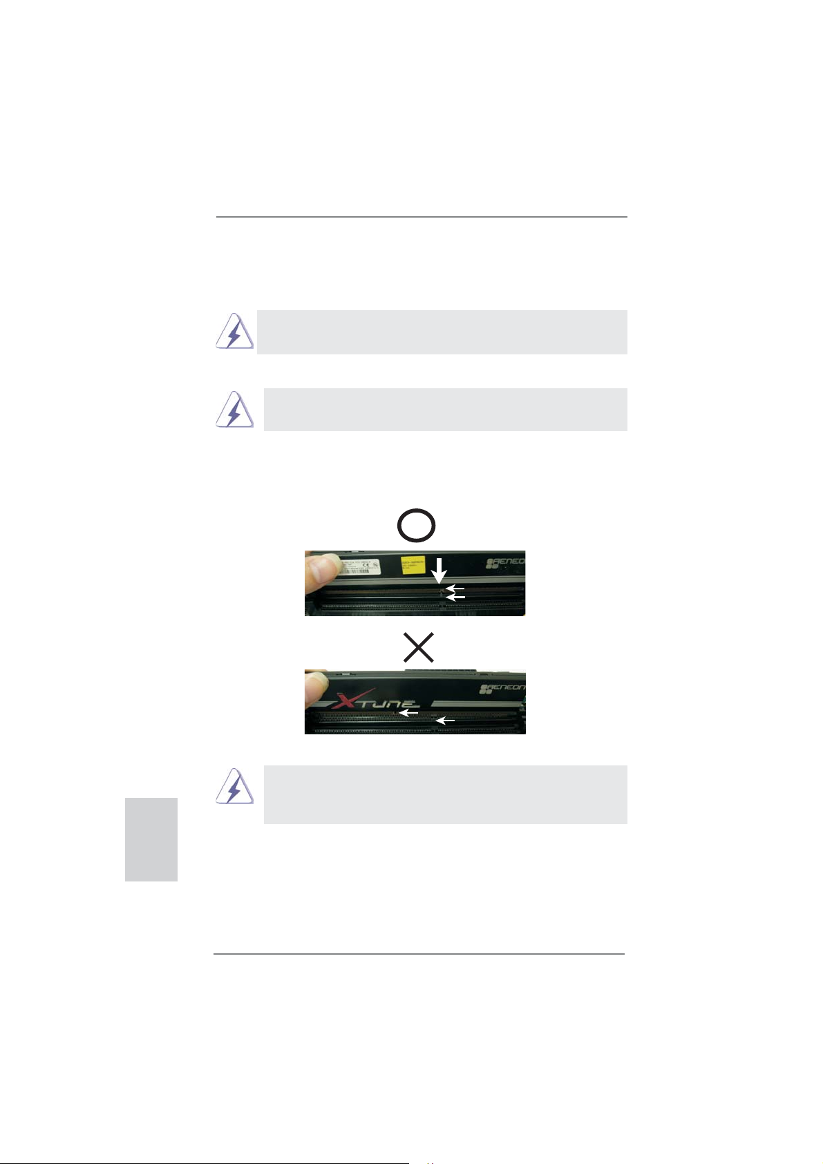
Step 2. Align a DIMM on the slot such that the notch on the DIMM matches the
break on the slot.
notch
break
English
12
notch
break
The DIMM only fi ts in one correct orientation. It will cause permanent
damage to the motherboard and the DIMM if you force the DIMM into
the slot at incorrect orientation.
Step 3. Firmly insert the DIMM into the slot until the retaining clips at both ends
fully snap back in place and the DIMM is properly seated.
ASRock E35LM1 R2.0 Motherboard
Page 13

2.4 Expansion Slot (PCI Express Slot)
There is 1 PCI Express slot on this motherboard.
PCIE slot:
PCIE1 (PCIE x16 slot) is used for PCI Express x4 lane width graphics
cards.
Installing an expansion card
Step 1. Before installing the expansion card, please make sure that the power
supply is switched off or the power cord is unplugged. Please read the
documentation of the expansion card and make necessary hardware
settings for the card before you start the installation.
Step 2. Remove the system unit cover (if your motherboard is already installed
in a chassis).
Step 3. Remove the bracket facing the slot that you intend to use. Keep the
screws for later use.
Step 4. Align the card connector with the slot and press fi rmly until the card is
completely seated on the slot.
Step 5. Fasten the card to the chassis with screws.
Step 6. Replace the system cover.
ASRock E35LM1 R2.0 Motherboard
English
13
Page 14
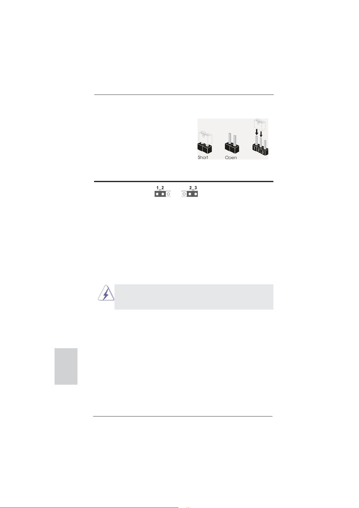
2.5 Jumpers Setup
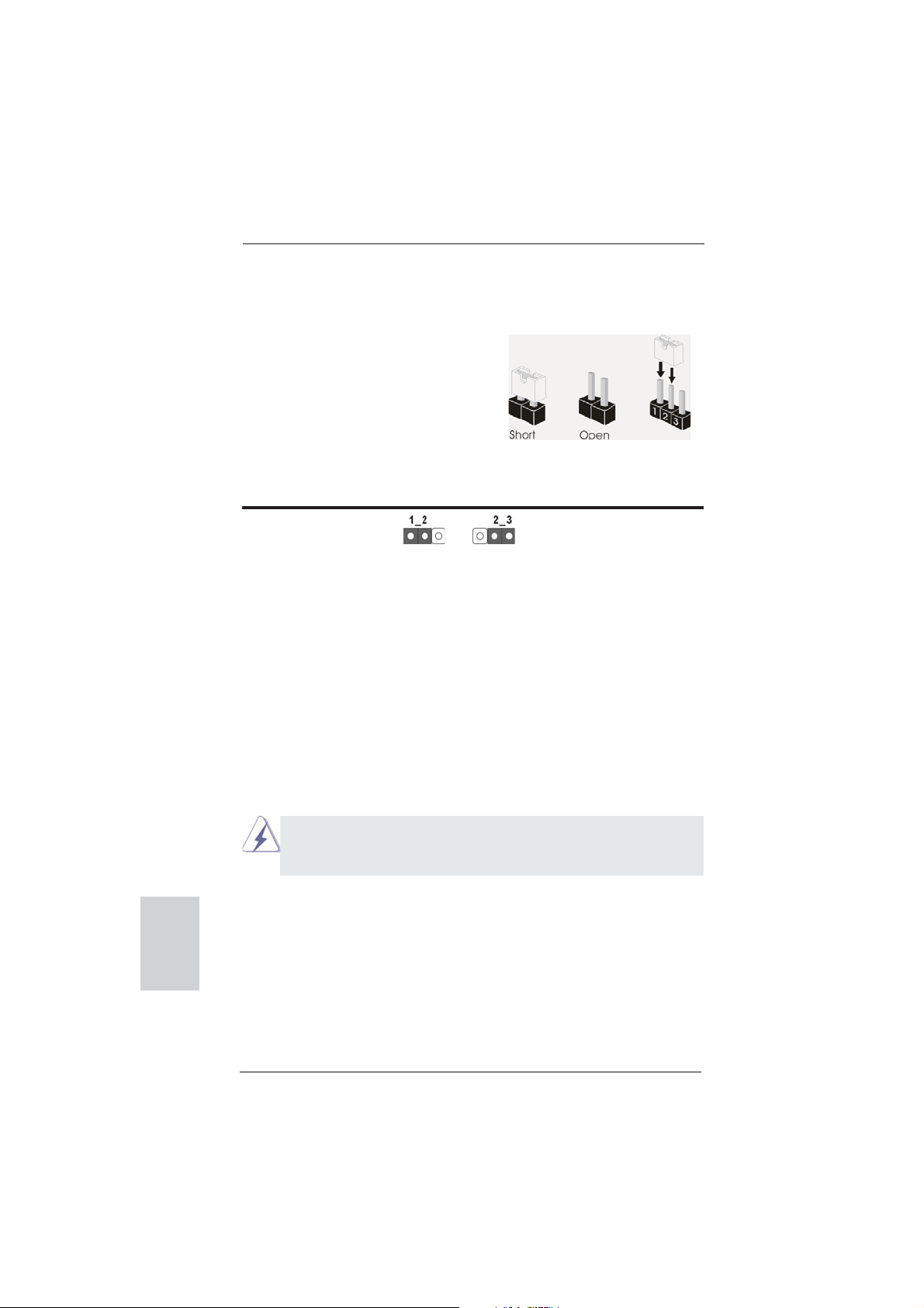
The illustration shows how jumpers are
setup. When the jumper cap is placed on
pins, the jumper is “Short”. If no jumper cap
is placed on pins, the jumper is “Open”. The
illustration shows a 3-pin jumper whose
pin1 and pin2 are “Short” when jumper cap
is placed on these 2 pins.
Jumper Setting Description
Clear CMOS Jumper
(CLRCMOS1)
(see p.2, No. 6)
Note: CLRCMOS1 allows you to clear the data in CMOS. To clear and reset the
system parameters to default setup, please turn off the computer and unplug
the power cord from the power supply. After waiting for 15 seconds, use a
jumper cap to short pin2 and pin3 on CLRCMOS1 for 5 seconds. However,
please do not clear the CMOS right after you update the BIOS. If you need
to clear the CMOS when you just fi nish updating the BIOS, you must boot
up the system fi rst, and then shut it down before you do the clear-CMOS ac-
tion. Please be noted that the password, date, time, user default profi le, 1394
GUID and MAC address will be cleared only if the CMOS battery is removed.
Clear CMOSDefault
English
14
If you clear the CMOS, the case open may be detected. Please adjust
the BIOS option “Clear Status” to clear the record of previous chassis
intrusion status.
ASRock E35LM1 R2.0 Motherboard
Page 15
2.6 Onboard Headers and Connectors
Onboard headers and connectors are NOT jumpers. Do NOT place
jumper caps over these headers and connectors. Placing jumper caps
over the headers and connectors will cause permanent damage of the
motherboard!
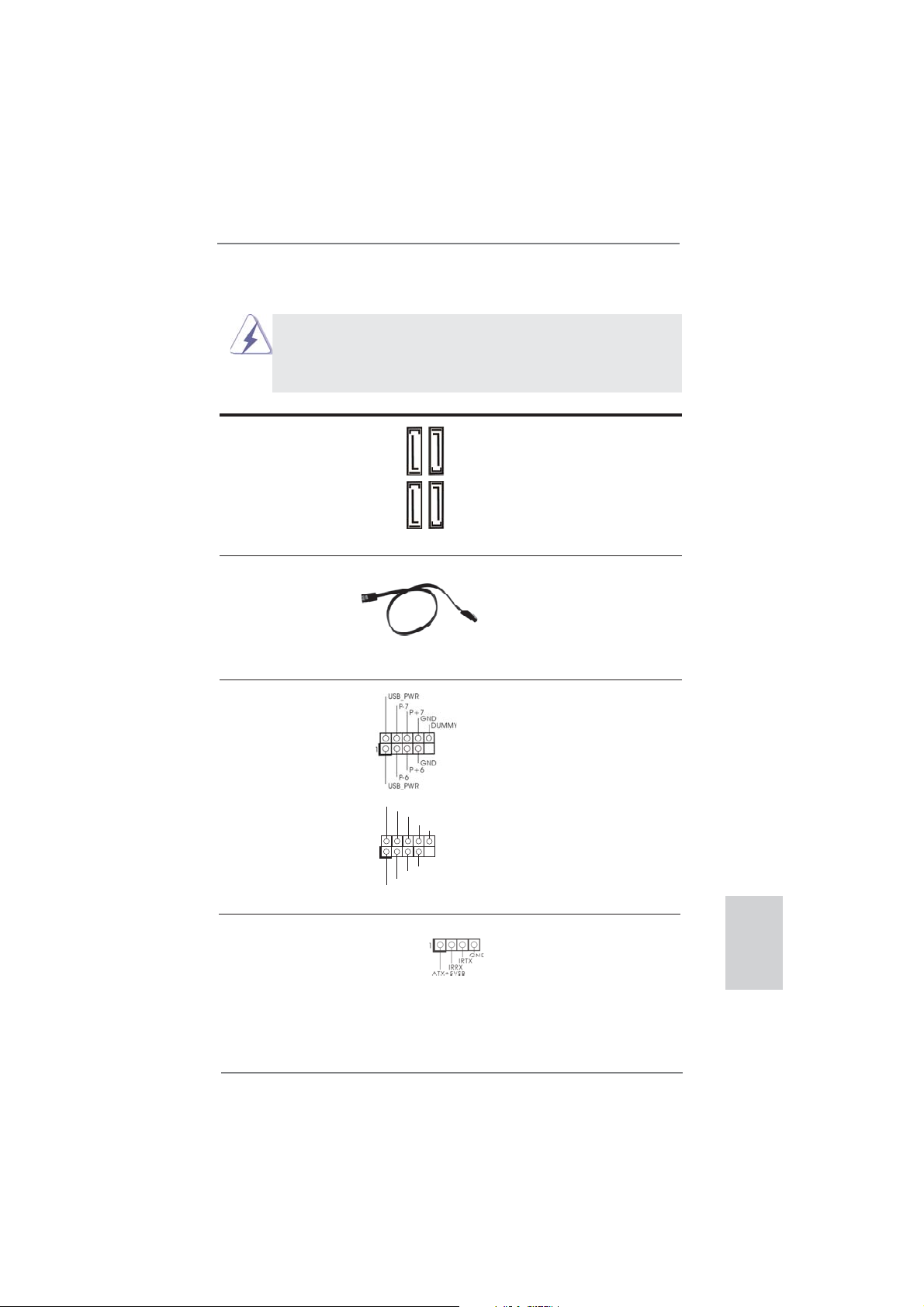
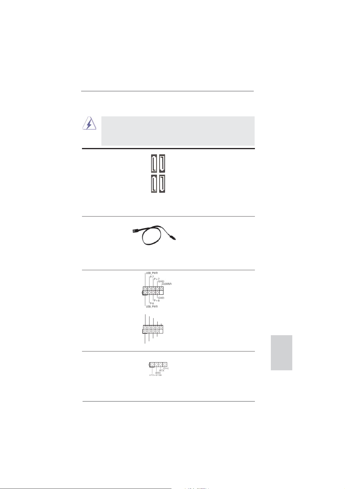
Serial ATA3 Connectors These four Serial ATA3 (SATA3)
(SATA3_1: see p.2, No. 12)
(SATA3_2: see p.2, No. 10)
(SATA3_3: see p.2, No. 11)
(SATA3_4: see p.2, No. 9)
data transfer rate.
Serial ATA (SATA) Either end of the SATA data
Data Cable cable can be connected to the
(Optional)
SATA / SATA2 / SATA3 hard
disk or the SATA2 / SATA3
connector on this motherboard.
USB 2.0 Headers Besides four default USB 2.0
(9-pin USB6_7)
(see p.2 No. 20)
ports on the I/O panel, there
are two USB 2.0 headers on
this motherboard. Each
USB 2.0 header can support
two USB 2.0 ports.
(9-pin USB8_9)
(see p.2 No. 19)
connectors support SATA data
cables for internal storage
SATA3_2
SATA3_4
devices. The current SATA3
interface allows up to 6.0 Gb/s
P+9
P+8
GND
GND
SATA3_3
DUMMY
1
SATA3_1
USB_PWR
P-9
P-8
USB_PWR
Consumer Infrared Module Header This header can be used to
(4-pin CIR1)
(see p.2 No. 18)
connect the remote
controller receiver.
ASRock E35LM1 R2.0 Motherboard
English
15
Page 16
Front Panel Audio Header This is an interface for front
(9-pin HD_AUDIO1)
(see p.2 No. 21)
panel audio cable that allows
convenient connection and
control of audio devices.
1
GND
PRESENCE#
MIC2_R
MIC2_L
MIC_RET
J_SENSE
OUT2_R
OUT_RET
OUT2_L
1. High Defi nition Audio supports Jack Sensing, but the panel wire on
the chassis must support HDA to function correctly. Please follow the
instruction in our manual and chassis manual to install your system.
2. If you use AC’97 audio panel, please install it to the front panel audio
header as below:
A. Connect Mic_IN (MIC) to MIC2_L.
B. Connect Audio_R (RIN) to OUT2_R and Audio_L (LIN) to OUT2_L.
C. Connect Ground (GND) to Ground (GND).
D. MIC_RET and OUT_RET are for HD audio panel only. You don’t
need to connect them for AC’97 audio panel.
E. To activate the front mic.
For Windows
Select “Mixer”. Select “Recorder”. Then click “FrontMic”.
For Windows
®
XP / XP 64-bit OS:
®
8 / 8 64-bit / 7 / 7 64-bit / VistaTM / VistaTM 64-bit OS:
Go to the "FrontMic" Tab in the Realtek Control panel. Adjust
“Recording Volume”.
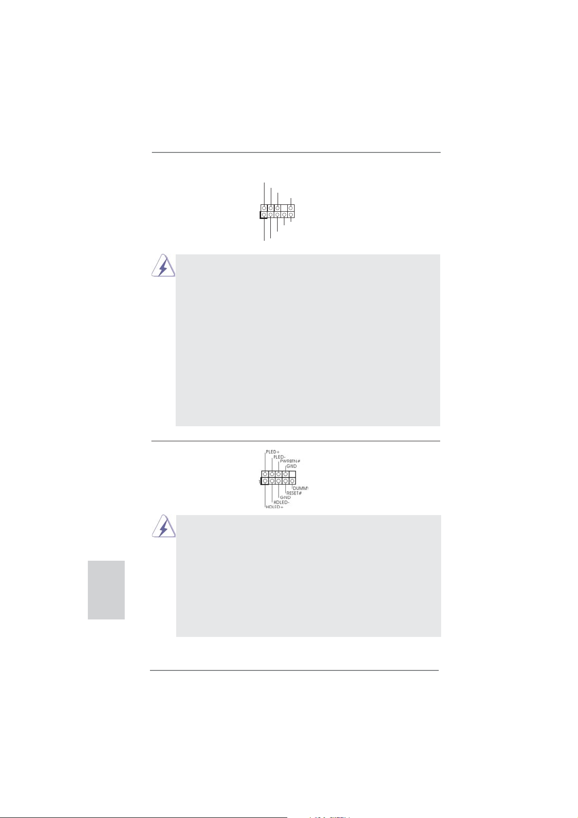
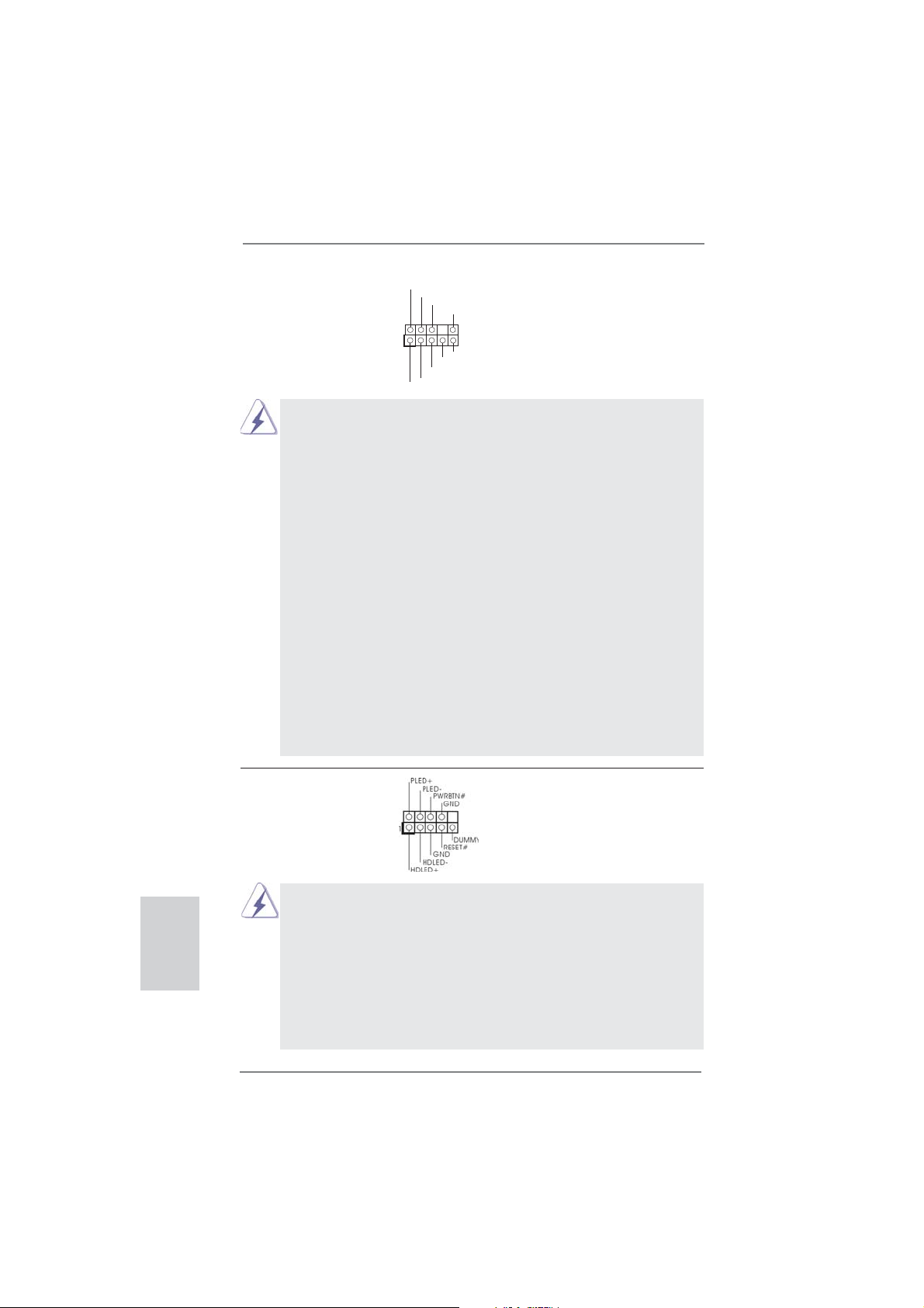
System Panel Header This header accommodates
(9-pin PANEL1)
(see p.2 No. 8)
several system front panel
functions.
English
16
Connect the power switch, reset switch and system status indicator on the
chassis to this header according to the pin assignments below. Note the
positive and negative pins before connecting the cables.
PWRBTN (Power Switch):
Connect to the power switch on the chassis front panel. You may confi gure
the way to turn off your system using the power switch.
RESET (Reset Switch):
Connect to the reset switch on the chassis front panel. Press the reset
switch to restart the computer if the computer freezes and fails to perform a
normal restart.
ASRock E35LM1 R2.0 Motherboard
Page 17
PLED (System Power LED):
Connect to the power status indicator on the chassis front panel. The LED
is on when the system is operating. The LED keeps blinking when the system is in S1 sleep state. The LED is off when the system is in S3/S4 sleep
state or powered off (S5).
HDLED (Hard Drive Activity LED):
Connect to the hard drive activity LED on the chassis front panel. The LED
is on when the hard drive is reading or writing data.
The front panel design may differ by chassis. A front panel module mainly
consists of power switch, reset switch, power LED, hard drive activity LED,
speaker and etc. When connecting your chassis front panel module to this
header, make sure the wire assignments and the pin assign-ments are
matched correctly.
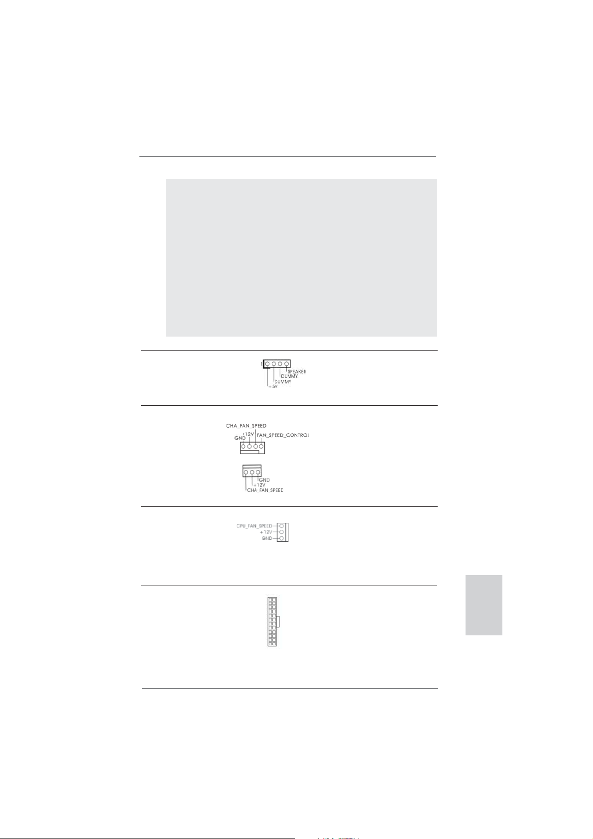
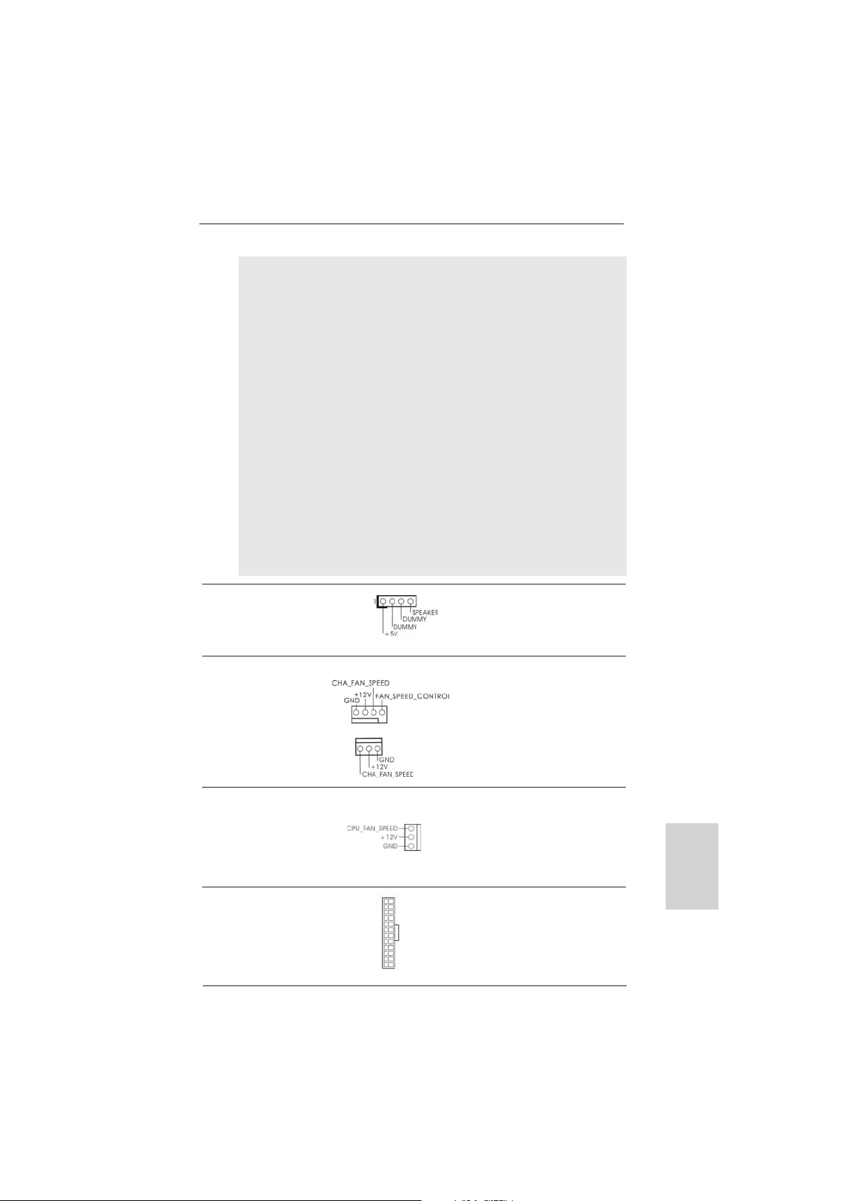
Chassis Speaker Header Please connect the chassis
(4-pin SPEAKER 1)
(see p.2 No. 15)
speaker to this header.
Chassis Fan Connectors Please connect the fan cables
(4-pin CHA_FAN1)
(see p.2 No. 2)
to the fan connectors and
match the black wire to the
ground pin. CHA_FAN2
supports fan speed control by
(3-pin CHA_FAN2)
(see p.2 No. 16)
fan power voltage.
CPU Fan Connectors Please connect the CPU fan
(3-pin CPU_FAN1)
(see p.2 No. 1)
cable to the connector and
match the black wire to the
ground pin. CPU_FAN1
supports fan speed control.
ATX Power Connector Please connect an ATX power
(24-pin ATXPWR1)
(see p.2 No. 7)
supply to this connector.
12 124
13
ASRock E35LM1 R2.0 Motherboard
English
17
Page 18
Though this motherboard provides 24-pin ATX power connector,
it can still work if you adopt a traditional 20-pin ATX power supply.
To use the 20-pin ATX power supply, please plug your
power supply along with Pin 1 and Pin 13.
12
24
20-Pin ATX Power Supply Installation
1
13
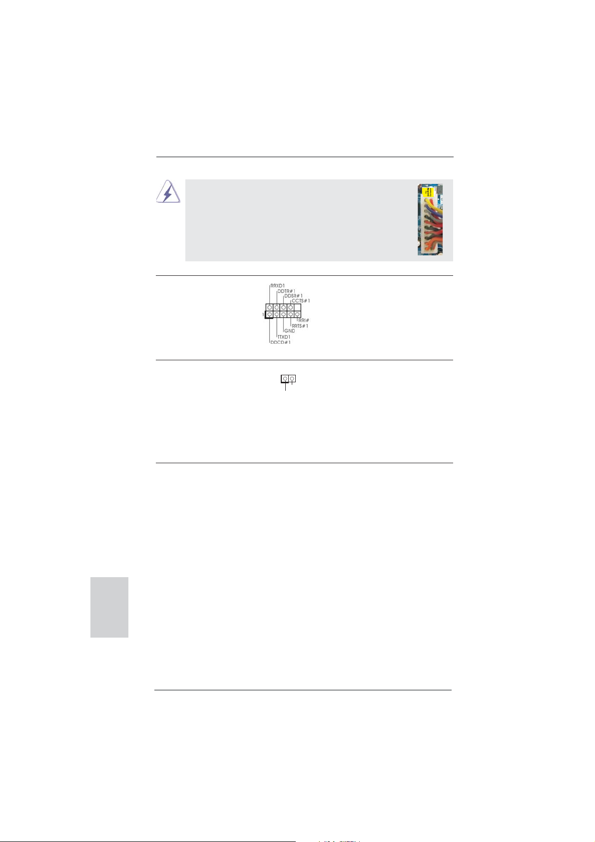
Serial port Header This COM1 header supports a
(9-pin COM1)
(see p.2 No. 22)
serial port module.
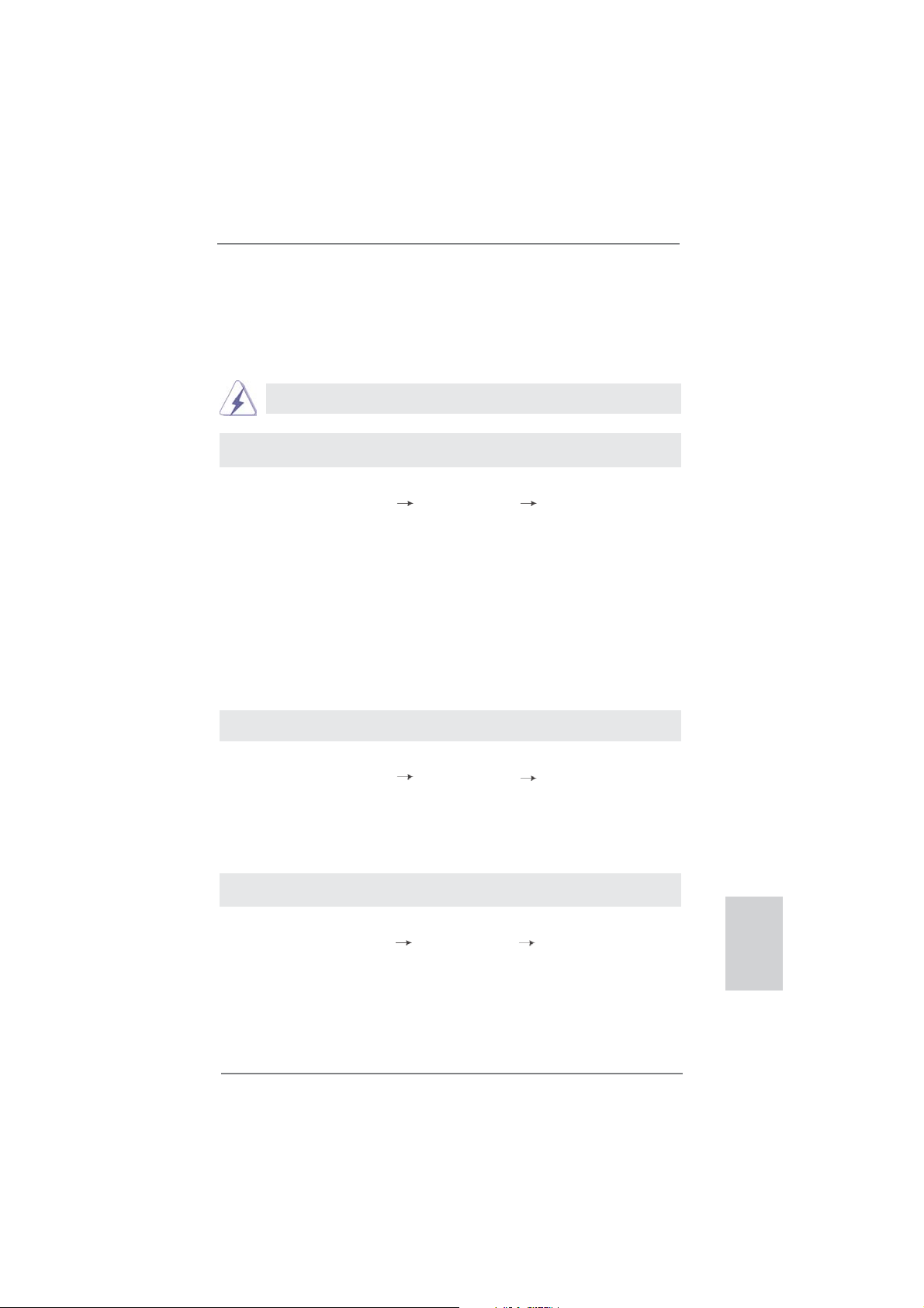
Chassis Intrusion Header This motherboard supports
(2-pin CI1)
CASE OPEN detection feature
(see p.2 No. 14)
that detects if the chassis cover
1
Signal
GND
has been removed. This feature
requires a chassis with chassis
intrusion detection design.
2.7 Driver Installation Guide
To install the drivers to your system, please insert the support CD to your optical
drive fi rst. Then, the drivers compatible to your system can be auto-detected and
listed on the support CD driver page. Please follow the order from up to bottom side
to install those required drivers. Therefore, the drivers you install can work properly.
English
18
2.8 Installing Windows® 8 / 8 64-bit / 7 / 7 64-bit / Vista
Vista
TM
64-bit / XP / XP 64-bit Without RAID Functions
TM
/
If you want to install Windows® 8 / 8 64-bit / 7 / 7 64-bit / VistaTM / VistaTM 64-bit / XP
/ XP 64-bit OS on your SATA3 HDDs without RAID functions, please follow below
procedures according to the OS you install.
ASRock E35LM1 R2.0 Motherboard
Page 19
2.8.1 Installing Windows® XP / XP 64-bit Without RAID
Functions
If you want to install Windows® XP / XP 64-bit OS on your SATA3 HDDs without
RAID functions, please follow below steps.
AHCI mode is not supported under Windows® XP / XP 64-bit OS.
Using SATA3 HDDs without NCQ function
STEP 1: Set up UEFI.
A. Enter UEFI SETUP UTILITY Advanced screen Storage Confi guration.
B. Set the option “SATA Mode” to [IDE].
STEP 2: Install Windows
®
XP / XP 64-bit OS on your system.
2.8.2 Installing Windows® 8 / 8 64-bit / 7 / 7 64-bit / Vista
Vista
TM
64-bit Without RAID Functions
TM
/
If you want to install Windows® 8 / 8 64-bit / 7 / 7 64-bit / VistaTM / VistaTM 64-bit OS
on your SATA3 HDDs without RAID functions, please follow below steps.
Using STA3 HDDs without NCQ function
STEP 1: Set up UEFI.
A. Enter UEFI SETUP UTILITY Advanced screen Storage Confi guration.
B. Set the option “SATA Mode” to [IDE].
STEP 2: Install Windows
®
8 / 8 64-bit / 7 / 7 64-bit / VistaTM / VistaTM 64-bit OS on
your system.
Using SATA3 HDDs with NCQ function
STEP 1: Set up UEFI.
A. Enter UEFI SETUP UTILITY Advanced screen Storage Confi guration.
B. Set the option “SATA Mode” to [AHCI].
STEP 2: Install Windows
®
8 / 8 64-bit / 7 / 7 64-bit / VistaTM / VistaTM 64-bit OS on
your system.
English
ASRock E35LM1 R2.0 Motherboard
19
Page 20

3. BIOS Information
The Flash Memory on the motherboard stores BIOS Setup Utility. When you start up
the computer, please press <F2> or <Del> during the Power-On-Self-Test (POST)
to enter BIOS Setup utility; otherwise, POST continues with its test routines. If you
wish to enter BIOS Setup after POST, please restart the system by pressing <Ctl>
+ <Alt> + <Delete>, or pressing the reset button on the system chassis. The BIOS
Setup program is designed to be user-friendly. It is a menu-driven program, which
allows you to scroll through its various sub-menus and to select among the predetermined choices. For the detailed information about BIOS Setup, please refer to the
User Manual (PDF fi le) contained in the Support CD.
4. Software Support CD information
®
This motherboard supports various Microsoft
64-bit / 7 / 7 64-bit / VistaTM / Vista
came with the motherboard contains necessary drivers and useful utilities that will
enhance motherboard features. To begin using the Support CD, insert the CD into
your CD-ROM drive. It will display the Main Menu automatically if “AUTORUN” is
enabled in your computer. If the Main Menu does not appear automatically, locate
and double-click on the fi le “ASSETUP.EXE” from the BIN folder in the Support CD
to display the menus.
TM
64-bit / XP / XP 64-bit. The Support CD that
Windows
®
operating systems: 8 / 8
English
20
ASRock E35LM1 R2.0 Motherboard
Page 21
1. Einführung
Wir danken Ihnen für den Kauf des ASRock E35LM1 R2.0 Motherboard, ein zuverlässiges Produkt, welches unter den ständigen, strengen Qualitätskontrollen von
ASRock gefertigt wurde. Es bietet Ihnen exzellente Leistung und robustes Design,
gemäß der Verpflichtung von ASRock zu Qualität und Halbarkeit. Diese Schnellinstallationsanleitung führt in das Motherboard und die schrittweise Installation
ein. Details über das Motherboard fi nden Sie in der Bedienungsanleitung auf der
Support-CD.
Da sich Motherboard-Spezifi kationen und BIOS-Software verändern
können, kann der Inhalt dieses Handbuches ebenfalls jederzeit geändert
werden. Für den Fall, dass sich Änderungen an diesem Handbuch
ergeben, wird eine neue Version auf der ASRock-Website, ohne weitere
Ankündigung, verfügbar sein. Die neuesten Grafi kkarten und unterstützten
CPUs sind auch auf der ASRock-Website aufgelistet.
ASRock-Website: http://www.asrock.com
Wenn Sie technische Unterstützung zu Ihrem Motherboard oder spezifi sche
Informationen zu Ihrem Modell benötigen, besuchen Sie bitte unsere
Webseite:
www.asrock.com/support/index.asp
1.1 Kartoninhalt
ASRock E35LM1 R2.0 Motherboard (Mini-ITX-Formfaktor)
ASRock E35LM1 R2.0 Schnellinstallationsanleitung
ASRock E35LM1 R2.0 Support-CD
Zwei Serial ATA (SATA) -Datenkabel (optional)
Ein I/O Shield
ASRock erinnert...
Zur besseren Leistung unter Windows® 8 / 8 64 Bit / 7 / 7 64 Bit / Vista
TM
Vista
64 Bit empfehlen wir, die Speicherkonfi guration im BIOS auf den
AHCI-Modus einzustellen. Hinweise zu den BIOS-Einstellungen fi nden
Sie in der Bedienungsanleitung auf der mitgelieferten CD.
TM
ASRock E35LM1 R2.0 Motherboard
/
Deutsch
21
Page 22
Deutsch
1.2 Spezifi kationen
Plattform - Mini-ITX-Formfaktor
CPU - AMD Zacate E-240 APU
- Unterstützt Cool ‘n’ Quiet
- UMI 2.5 GT/s
Chipsatz - AMD A50M Chipsatz
Speicher - 2 x Steckplätze für DDR3
- Unterstützt DDR3 1333(OC)/1066/800 non-ECC,
ungepufferter Speicher
- Max. Kapazität des Systemspeichers: 16GB
Erweiterungs- - 1 x PCI Express 2.0 x16-Steckplatz (PCIE1 für x4-Modus)
steckplätze
Onboard-VGA - Integrierte AMD Radeon HD 6310-Grafi k
- DX11 Klasse iGPU, Pixel Shader 5.0
- Maximal gemeinsam genutzter Speicher 512MB
- Unterstützt D-Sub mit einer maximalen Aufl ösung von
2560 x 1600 bei 60 Hz
Audio - 5.1
CH HD Audio (Realtek ALC662 Audio Codec)
LAN - PCIE x1 Gigabit LAN 10/100/1000 Mb/s
- Realtek RTL8111E
- Unterstützt Wake-On-LAN
- Unterstützt LAN-Kabelerkennung
- Unterstützt energieeffi zientes Ethernet 802.3az
- Unterstützt PXE
E/A-Anschlüsse I/O Panel
an der - 1 x PS/2-Tastaturanschluss/Mausanschluss
Rückseite - 1 x VGA port
- 4 x Standard-USB 2.0-Anschlüsse
- 1 x RJ-45 LAN Port mit LED (ACT/LINK LED und SPEED
LED)
- HD Audiobuchse: Audioeingang / Lautsprecher vorne /
Mikrofon
SATA3 - 4 x SATA 3-Anschlüsse (6,0 Gb/s); unterstützt NCQ-, AHCI und „Hot Plug“ (Hot-Plugging)-Funktionen
Anschlüsse - 4 x SATA3 6,0 GB/s-Anschlüsse
- 1 x
Consumer Infrared-Modul-Header
- 1 x COM-Anschluss-Header
- 1 x Verteiler für Gehäuseeindringversuche
- 1 x CPUlüfter-Anschluss (3-pin)
- 2 x Gehäuselüfter-Anschluss (1 x 4-pin, 1 x 3-pin)
TM
-Technologie von AMD
22
ASRock E35LM1 R2.0 Motherboard
Page 23
- 24-pin ATX-Netz-Header
- Anschluss für Audio auf der Gehäusevorderseite
- 2 x USB 2.0-Anschlüsse (Unterstützung 4 zusätzlicher
USB 2.0-Anschlüsse)
BIOS - 32Mb AMIs Legal BIOS UEFI mit GUI-Unterstützung
- Unterstützung für “Plug and Play”
- ACPI 1.1-Weckfunktionen
- JumperFree-Übertaktungstechnologie
- SMBIOS 2.3.1
- DRAM, FCH, +1V, +1.8V Stromspannung Multianpassung
CD d’assistance - Treiber, Dienstprogramme, Antivirussoftware (Probeversion),
CyberLink MediaEspresso 6.5-Testversion, ASRock
MAGIX-Multimedia-Suite - OEM, Google Chrome Browser
und Toolbar
Hardware Monitor - Überwachung der CPU-Temperatur
- Motherboardtemperaturerkennung
- Drehzahlmessung für CPUlüfter
- Drehzahlmessung für Gehäuselüfter
- Geräuscharmer CPU-lüfter (ermöglicht die au tomatische
Anpassung der Gehäuselüftergeschwindigkeit durch CPU Temperatur)
- Mehrstufi ge Geschwindigkeitssteuerung für CPU/Gehäuse
lüfter
- GEHÄUSE OFFEN-Erkennung
- Spannungsüberwachung: +12V, +5V, +3.3V, Vcore
Betriebssysteme - Unterstützt Microsoft
VistaTM / Vista
TM
64-Bit / XP / XP 64-Bit
®
Windows
®
8 / 8 64-Bit / 7 / 7 64-Bit /
Zertifi zierungen - FCC, CE, WHQL
- Gemäß Ökodesign-Richtlinie (ErP/EuP) (Stromversorgung
gemäß Ökodesign-Richtlinie (ErP/EuP) erforderlich)
* Für die ausführliche Produktinformation, besuchen Sie bitte unsere Website:
http://www.asrock.com
ASRock E35LM1 R2.0 Motherboard
Deutsch
23
Page 24
1.3 Einstellung der Jumper
Die Abbildung verdeutlicht, wie Jumper
gesetzt werden. Werden Pins durch
Jumperkappen verdeckt, ist der Jumper
“Gebrückt”. Werden keine Pins durch
Jumperkappen verdeckt, ist der Jumper
“Offen”. Die Abbildung zeigt einen 3-Pin
Jumper dessen Pin1 und Pin2 “Gebrückt” sind, bzw. es befi ndet sich eine
Jumper-Kappe auf diesen beiden Pins.
Jumper Einstellun Beschreibung
CMOS löschen
(CLRCMOS1, 3-Pin jumper)
(siehe S.2, No. 6)
Hinweis:
CLRCMOS1 ermöglicht Ihnen die Löschung der Daten im CMOS. Zum
Löschen und Zurücksetzen der Systemparameter auf die Standardeinrichtung
schalten Sie den Computer bitte aus und trennen das Netzkabel von der
Stromversorgung. Warten Sie 15 Sekunden, schließen Sie dann Pin2 und
Pin3 am CLRCMOS1 über einen Jumper fünf Sekunden lang kurz. Sie
sollten das CMOS allerdings nicht direkt nach der BIOS-Aktualisierung
löschen. Wenn Sie das CMOS nach Abschluss der BIOS-Aktualisierung
löschen müssen, fahren Sie zuerst das System hoch. Fahren Sie es dann
vor der CMOS-Löschung herunter. Bitte beachten Sie, dass Kennwort,
Datum, Uhrzeit, benutzerdefi niertes Profi l, 1394 GUID und MAC-Adresse
nur gelöscht werden, wenn die CMOS-Batterie entfernt wird.
DefaultEinstellung
CMOS
löschen
Deutsch
24
Durch Löschen des CMOS kann erkannt werden, wenn das Gehäuseoffen
ist. Bitte stellen Sie zum Löschen der Aufzeichnung des vorherigenGehäuseindringungsstatus die BIOS-Option “Status leeren” ein.
ASRock E35LM1 R2.0 Motherboard
Page 25
1.4 Integrierte Header und Anschlüsse
Seriell-ATA3-Anschlüsse Diese vier Serial ATA3-
(SATA3_1: siehe S.2 - No. 12)
(SATA3_2: siehe S.2 - No. 10)
(SATA3_3: siehe S.2 - No. 11)
(SATA3_4: siehe S.2 - No. 9)
aktuelle SATA3- Schnittstelle
ermöglicht eine
Datenübertragungsrate bis
6,0 Gb/s.
Serial ATA- (SATA-) SJedes Ende des SATA
Datenkabel Datenkabels kann an die SATA
(Option)
oder das SATAII / SATA3
Verbindungsstück auf
dieser Hauptplatine
angeschlossen werden.
USB 2.0-Header Zusätzlich zu den vier
(9-pol. USB6_7)
(siehe S.2 - No. 20)
zwei USB 2.0-
Anschlussleisten am
Motherboard. Pro USB 2.0-
(9-pol. USB8_9)
(siehe S.2 - No. 19)
Integrierte Header und Anschlüsse sind KEINE Jumper. Setzen Sie KEINE Jumperkappen auf diese Header und Anschlüsse. Wenn Sie Jumperkappen auf Header und Anschlüsse setzen, wird das Motherboard
unreparierbar beschädigt!
(SATA3-)Verbínder
unterstützten SATA-Datenkabel
für interne
SATA3_2
SATA3_4
Massenspeichergeräte. Die
SATA3_1
SATA3_3
/ SATAII / SATA3 Festplatte
üblichen USB 2.0-Ports an den
I/O-Anschlüssen befi nden sich
USB_PWR
1
P-9
P-8
USB_PWR
P+9
P+8
GND
GND
DUMMY
Anschlussleiste werden zwei
USB 2.0-Ports unterstützt.
Consumer Infrared-Modul-Header Dieser Header kann zum
(4-pin CIR1)
(siehe S.2 - No. 18)
Anschließen Remote-
Empfänger.
ASRock E35LM1 R2.0 Motherboard
Deutsch
25
Page 26
Anschluss für Audio auf Dieses Interface zu einem
der Gehäusevorderseite Audio-Panel auf der Vorder
(9-Pin HD_AUDIO1)
(siehe S.2 - No. 21)
seite Ihres Gehäuses,
ermöglicht Ihnen eine bequeme
Anschlussmöglichkeit und
Kontrolle über Audio-Geräte.
1
GND
PRESENCE#
MIC2_R
MIC2_L
MIC_RET
J_SENSE
OUT2_R
OUT_RET
OUT2_L
1. High Defi nition Audio unterstützt Jack Sensing (automatische Erkennung
falsch angeschlossener Geräte), wobei jedoch die Bildschirmverdrahtung
am Gehäuse HDA unterstützen muss, um richtig zu funktionieren.
Beachten Sie bei der Installation im System die Anweisungen in unserem
Handbuch und im Gehäusehandbuch.
2. Wenn Sie die AC’97-Audioleiste verwenden, installieren Sie diese wie
nachstehend beschrieben an der Front-Audioanschlussleiste:
A. Schließen Sie Mic_IN (MIC) an MIC2_L an.
B. Schließen Sie Audio_R (RIN) an OUT2_R und Audio_L (LIN) an OUT2_L an.
C. Schließen Sie Ground (GND) an Ground (GND) an.
D. MIC_RET und OUT_RET sind nur für den HD-Audioanschluss gedacht. Diese
Anschlüsse müssen nicht an die AC’97-Audioleiste angeschlossen werden.
E. So aktivieren Sie das Mikrofon an der Vorderseite.
Bei den Betriebssystemen Windows
®
XP / XP 64 Bit:
Wählen Sie „Mixer“. Wählen Sie „Recorder“ (Rekorder). Klicken Sie dann
auf „FrontMic“ (Vorderes Mikrofon).
Bei den Betriebssystemen Windows® 8 / 8 64 Bit / 7 / 7 64 Bit / VistaTM / VistaTM
64 Bit:
Wählen Sie im Realtek-Bedienfeld die „FrontMic“ (Vorderes Mikrofon)-
Registerkarte. Passen Sie die „Recording Volume“ (Aufnahmelautstärke)
an.
Deutsch
26
System Panel-Header Dieser Header unterstützt
(9-pin PANEL1)
(siehe S.2 - No. 8)
Schließen Sie die Ein-/Austaste, die Reset-Taste und die
Systemstatusanzeige am Gehäuse an diesen Header an; befolgen Sie
dabei die nachstehenden Hinweise zur Pinbelegung. Beachten Sie die
positiven und negativen Pins, bevor Sie die Kabel anschließen.
PWRBTN (Ein-/Ausschalter):
mehrere Funktion der
Systemvorderseite.
Zum Anschließen des Ein-/Ausschalters an der Frontblende des Gehäu
ses. Sie können konfi gurieren, wie das System mit Hilfe des
Ein-/Ausschalters ausgeschaltet werden können soll.
ASRock E35LM1 R2.0 Motherboard
Page 27
RESET (Reset-Taste):
Zum Anschließen der Reset-Taste an der Frontblende des Gehäuses.
Mit der Reset-Taste können Sie den Computer im Falle eines Absturzes
neu starten.
PLED (Systembetriebs-LED):
Zum Anschließen der Betriebsstatusanzeige an der Frontblende des
Gehäuses. Die LED leuchtet, wenn das System in Betrieb ist. Die LED
blinkt, wenn sich das System im Ruhezustand S1 befi ndet. Die LED
schaltet sich aus, wenn sich das System in den Modi S3/S4 befi ndet
oder ausgeschaltet ist (S5).
HDLED (Festplattenaktivitäts-LED):
Zum Anschließen der Festplattenaktivitäts-LED an der Frontblende des
Gehäuses. Die LED leuchtet, wenn die Festplatte Daten liest oder
schreibt.
Das Design der Frontblende kann je nach Gehäuse variiere. Ein
Frontblendenmodul besteht hauptsächlich aus einer Ein-/Austaste, einer
Reset-Taste, einer Betriebs-LED, einer Festplattenaktivitäts-LED,
Lautsprechern, etc. Stellen Sie beim Anschließen des
Frontblendenmoduls Ihres Gehäuses an diesem Header sicher, dass die
Kabel- und Pinbelegung korrekt übereinstimmen.
Gehäuselautsprecher-Header Schließen Sie den
(4-pin SPEAKER1)
(siehe S.2 - No. 15)
Gehäuselautsprecher an
diesen Header an.
Gehäuse lüfteranschlüsse
(4-pin CHA_FAN1)
(siehe S.2 - No. 2)
Verbinden Sie die Lüfterkabel mit
den Lüfteranschlüssen, wobei
der schwarze Draht an den
Schutzleiterstift angeschlossen
(3-pin CHA_FAN2)
(siehe S.2 - No. 16)
wird.
CPU-Lüfteranschluss Verbinden Sie das CPU -
(3-pin CPU_FAN1)
(siehe S.2 - No. 1)
Lüfterkabel mit diesem
Anschluss und passen Sie den
schwarzen Draht dem
Erdungsstift an.
ATX-Netz-Header Verbinden Sie die ATX-
(24-pin ATXPWR1)
(siehe S.2 - No. 7)
Stromversorgung mit diesem
Header.
12 124
13
ASRock E35LM1 R2.0 Motherboard
Deutsch
27
Page 28
Obwohl dieses Motherboard einen 24-pol. ATX-
12
24
Stromanschluss bietet, kann es auch mit einem
modifi zierten traditionellen 20-pol. ATX-Netzteil
verwendet werden. Um ein 20-pol. ATX-Netzteil zu
verwenden, stecken Sie den Stecker mit Pin 1 und
Pin 13 ein.
Installation eines 20-pol. ATX-Netzteils
1
13
COM-Anschluss-Header Dieser COM-Anschluss-
(9-pin COM1)
(siehe S.2 - No. 22)
Header wird verwendet, um
ein COM-Anschlussmodul zu
unterstützen.
Verteiler für Gehäuseeindringversuche Dieses Motherboard unterstützt
(2-pin CI1)
die GEHÄUSE OFFEN-
(siehe S.2 - No. 14)
Erkennungsfunktion,die
feststellt, ob dieGehäuseab-
1
Signal
GND
deckung entferntwurde. Für
diese Funktion istein Ge häuse erforderlich, dasmit ei nem Design zur Erkennung
von Gehäuseeindringver suchenausgestattet ist.
Deutsch
28
ASRock E35LM1 R2.0 Motherboard
Page 29

2. BIOS-Information
Das Flash Memory dieses Motherboards speichert das Setup-Utility. Drücken Sie
<F2> oder <Del> während des POST (Power-On-Self-Test) um ins Setup zu gelangen, ansonsten werden die Testroutinen weiter abgearbeitet. Wenn Sie ins Setup
gelangen wollen, nachdem der POST durchgeführt wurde, müssen Sie das System
über die Tastenkombination <Ctrl> + <Alt> + <Delete> oder den Reset-Knopf auf
der Gehäusevorderseite, neu starten. Natürlich können Sie einen Neustart auch
durchführen, indem Sie das System kurz ab- und danach wieder anschalten.
Das Setup-Programm ist für eine bequeme Bedienung entwickelt worden. Es ist
ein menügesteuertes Programm, in dem Sie durch unterschiedliche Untermenüs
scrollen und die vorab festgelegten Optionen auswählen können. Für detaillierte
Informationen zum BIOS-Setup, siehe bitte das Benutzerhandbuch (PDF Datei) auf
der Support CD.
3. Software Support CD information
Dieses Motherboard unterstützt eine Reiche von Microsoft® Windows® Betriebssystemen: 8 / 8 64-Bit / 7 / 7 64-Bit / Vista
Ihrem Motherboard beigefügte Support-CD enthält hilfreiche Software, Treiber und
Hilfsprogramme, mit denen Sie die Funktionen Ihres Motherboards verbessern können Legen Sie die Support-CD zunächst in Ihr CD-ROM-Laufwerk ein. Der Willkommensbildschirm mit den Installationsmenüs der CD wird automatisch aufgerufen,
wenn Sie die “Autorun”-Funktion Ihres Systems aktiviert haben.
Erscheint der Wilkommensbildschirm nicht, so “doppelklicken” Sie bitte auf das File
ASSETUP.EXE im BIN-Verzeichnis der Support-CD, um die Menüs aufzurufen.
Das Setup-Programm soll es Ihnen so leicht wie möglich machen. Es ist menügesteuert, d.h. Sie können in den verschiedenen Untermenüs Ihre Auswahl treffen und
die Programme werden dann automatisch installiert.
TM
/ Vista
TM
64-Bit / XP / XP 64-Bit. Die
ASRock E35LM1 R2.0 Motherboard
Deutsch
29
Page 30

1. Introduction
Merci pour votre achat d’une carte mère ASRock E35LM1 R2.0, une carte mère
très fi able produite selon les critères de qualité rigoureux de ASRock. Elle offre des
performances excellentes et une conception robuste conformément à l’engagement
d’ASRock sur la qualité et la fi abilité au long terme.
Ce Guide d’installation rapide présente la carte mère et constitue un guide
d’installation pas à pas. Des informations plus détaillées concernant la carte
mère pourront être trouvées dans le manuel l’utilisateur qui se trouve sur le CD
d’assistance.
Les spécifi cations de la carte mère et le BIOS ayant pu être mis à
jour, le contenu de ce manuel est sujet à des changements sans
notifi cation. Au cas où n’importe qu’elle modifi cation intervenait sur ce
manuel, la version mise à jour serait disponible sur le site web
ASRock sans nouvel avis. Vous trouverez les listes de prise en
charge des cartes VGA et CPU également sur le site Web ASRock.
Site web ASRock, http://www.asrock.com
Si vous avez besoin de support technique en relation avec cette carte
mère, veuillez consulter notre site Web pour de plus amples
informations particulières au modèle que vous utilisez.
www.asrock.com/support/index.asp
1.1 Contenu du paquet
Carte mère ASRock E35LM1 R2.0 (Facteur de forme Mini-ITX)
Guide d’installation rapide ASRock E35LM1 R2.0
CD de soutien ASRock E35LM1 R2.0
Deux câbles de données de série ATA (SATA) (en option)
Un I/O Panel Shield
Français
30
ASRock vous rappelle...
Pour bénéfi cier des meilleures performances sous Windows® 8 / 8 64 bits
/ 7 / 7 64 bits / Vista
l'option BIOS dans Confi guration de stockage en mode AHCI. Pour plus
de détails sur l'installation BIOS, référez-vous au "Mode d'emploi" sur
votre CD de support.
TM
/ VistaTM 64 bits, il est recommandé de paramétrer
ASRock E35LM1 R2.0 Motherboard
Page 31

1.2 Spécifi cations
Format - Facteur de forme Mini-ITX
CPU - AMD Zacate E-240 APU
- Supporte la technologie Cool ‘n’ Quiet
- UMI 2.5 GT/s
Chipsets - AMD A50M Chipsets
Mémoire - 2 x slots DIMM DDR3
- Supporter DDR3 1333(OC)/1066/800 non-ECC, sans
amortissement mémoire
- Capacité maxi de mémoire système: 16GB
Slot d’extension - 1 x slot PCI Express 2.0 x16 (PCIE1 @ mode x4)
VGA sur carte - Graphiques intégrés à l’AMD Radeon HD 6310
- DX11 classe iGPU, nuanceur de pixels 5.0
- mémoire partagée max 512MB
- Prend en charge le D-Sub avec une résolution maximale
jusqu’à 2560x1600 @ 60Hz
Audio - 5,1 CH HD Audio (Realtek ALC662 Audio Codec)
LAN - PCIE x1 Gigabit LAN 10/100/1000 Mb/s
- Realtek RTL8111E
- Support du Wake-On-LAN
- Prise en charge de la détection de câble LAN
- Prend en charge la norme Energy Effi cient Ethernet
(Ethernet à effi cacité énergétique) 802.3az
- Supporte PXE
Panneau arrière I/O Panel
- 1 x port clavier/souris PS/2
- 1 x port VGA
- 4 x ports USB 2.0 par défaut
- 1 x port LAN RJ-45 avec LED (ACT/LED CLIGNOTANTE et
LED VITESSE)
- Prise HD Audio: Entrée Ligne / Haut-parleur frontal /
Microphone
SATA 3 - 4 x connecteurs SATA3 6,0 Gb/s, prennent en charge les
fonctions NCQ, AHCI et « Hot Plug » (Branche ment à
chaud)
Connecteurs - 4 x connecteurs SATA3, prennent en charge un taux de
transfert de données pouvant aller jusqu’à 6.0Go/s
- 1 x
- 1 x En-tête de port COM
- 1 x Embase d’intrusion châssis
Barrette pour module à infrarouges grand public
TM
d’AMD
Français
ASRock E35LM1 R2.0 Motherboard
31
Page 32

- 1 x Connecteur pour ventilateur de CPU (br. 3)
- 2 x Connecteur pour ventilateur de Châssis
(1 x br. 4, 1 x br. 3)
- br. 24 connecteur d’alimentation ATX
- Connecteur audio panneau avant
- 2 x En-tête USB 2.0 (prendre en charge 4 ports USB 2.0
supplémentaires)
BIOS - 32Mb AMI UEFI Legal BIOS avec support GUI
- Support du “Plug and Play”
- Compatible pour événements de réveil ACPI 1.1
- Gestion jumperless
- Support SMBIOS 2.3.1
- DRAM, FCH, +1V, +1.8V Tension Multi-ajustement
CD d’assistance - Pilotes, utilitaires, logiciel anti-virus (version d’évaluation),
CyberLink MediaEspresso 6.5 Trial, Suite multimédia
ASRock MAGIX - OEM, Google Chrome Browser et Toolbar
Surveillance - Contrôle de la température CPU
système - Mesure de température de la carte mère
- Tachéomètre ventilateur processeur
- Tachéomètre ventilateur châssis
- Ventilateur silencieux pour unité centrale (permet le réglage
automatique de la vitesse du ventilateur pour châssis, selon
la température de l’unité centrale)
- Commande de ventilateur processeur/châssis à plusieurs
vitesses
- Détection d’OUVERTURE DE BOÎTIER
- Monitoring de la tension: +12V, +5V, +3.3V, Vcore
OS - Microsoft
Vista
®
Windows® 8 / 8 64-bit / 7 / 7 64-bit / VistaTM /
TM
64-bit / XP / XP 64-bit
Certifi cations - FCC, CE, WHQL
- Prêt pour ErP/EuP (alimentation Prêt pour ErP/EuP requise)
* Pour de plus amples informations sur les produits, s’il vous plaît visitez notre site web:
http://www.asrock.com
Français
32
ASRock E35LM1 R2.0 Motherboard
Page 33

1.3 Réglage des cavaliers
L’illustration explique le réglage des cavaliers. Quand un capuchon est placé sur les
broches, le cavalier est « FERME ». Si aucun capuchon ne relie les broches,le cavalier est « OUVERT ». L’illustration montre un
cavalier à 3 broches dont les broches 1 et 2
sont « FERMEES » quand le capuchon est
placé sur ces 2 broches.
Le cavalier Description
Effacer la CMOS
(CLRCMOS1)
(voir p.2 fi g. 6)
Remarque :
Paramètres
par défaut
CLRCMOS1 vous permet d’effacer les données du CMOS. Pour effacer
et réinitialiser les paramètres du système à la confi guration originale,
veuillez éteindre l’ordinateur et débrancher le cordon d’alimentation de
la prise de courant. Après 15 secondes, utilisez un couvercle de jumper
pour court-circuiter les broches pin2 et pin3 de CLRCMOS1 pendant
secondes. Veuillez cependant ne pas effacer le CMOS immédiatement
a
près avoir mis à jour le BIOS. Si vous avez besoin d’effacer le CMOS
après avoir mis à jour le BIOS, vous devez allumer en premier le
système, puis l’éteindre avant de continuer avec l’opération d’effacement
du CMOS. Veuillez noter que le mot de passe, la date, l’heure, le profi l
par défaut de l’utilisateur, 1394 GUID et l’adresse MAC seront effacés
seulement si la batterie du CMOS est enlevée.
Effacer la
CMOS
5
Si vous effacez la CMOS, il se peut qu’une ouverture du boîtier soitdé-
tectée. Veuillez ajuster l’option du BIOS “Clear Status” (Effacerl’état) pour
effacer la mention d’état d’intrusion dans le châssis.
ASRock E35LM1 R2.0 Motherboard
Français
33
Page 34

1.4 En-têtes et Connecteurs sur Carte
Connecteurs Série ATA3 Ces quatre connecteurs Série
(SATA3_1: voir p.2 No. 12)
(SATA3_2: voir p.2 No. 10)
(SATA3_3: voir p.2 No. 11)
(SATA3_4: voir p.2 No. 9)
actuelle permet des taux
transferts de données pouvant
aller jusqu’à 6,0 Gb/s.
Câble de données Toute cote du cable de data
Série ATA (SATA) SATA peut etre connecte au
(en option)
SATA3 ou au connecteur
SATAII / SATA3 sur la carte
mere.
Les en-têtes et connecteurs sur carte NE SONT PAS des cavaliers.
NE PAS placer les capuchons de cavalier sur ces en-têtes et connecteurs. Le fait de placer les capuchons de cavalier sur les en-têtes
et connecteurs causera à la carte mère des dommages irréversibles!
ATA3 (SATA3) prennent en
charge les câbles SATA pour
les périphériques de stockage
SATA3_2
SATA3_4
internes. L’interface SATA3
SATA3_1
SATA3_3
disque dur SATA / SATAII /
Français
34
1
1
USB_PWR
P-9
P-8
USB_PWR
USB_PW R
P-11
P-10
USB_PW R
P+9
P+8
P+11
P+10
GND
GND
GND
GND
DUMMY
DUMMY
En-tête USB 2.0 A côté des quatre ports
(USB6_7 br.9)
(voir p.2 No. 20)
USB 2.0 par défaut sur le
panneau E/S, il y a deux
embases USB 2.0 sur cette
carte mère. Chaque embase
USB 2.0 peut prendre en
(USB8_9 br.9)
(voir p.2 No. 19)
charge 2 ports USB 2.0.
Barrette pour module à infrarouges grand public Cette barrette peut être utilisée
(CIR1 br.4)
(voir p.2 No. 18)
pour connecter des récepteur.
ASRock E35LM1 R2.0 Motherboard
Page 35

Connecteur audio panneau C’est une interface pour
(HD_AUDIO1 br. 9)
(voir p.2 No. 21)
un câble avant audio en façade
qui permet le branchement et
le contrôle commodes de
périphériques audio.
1
GND
PRESENCE#
MIC2_R
MIC2_L
MIC_RET
J_SENSE
OUT2_R
OUT_RET
OUT2_L
1. L’audio à haute défi nition (HDA) prend en charge la détection de fi che,
mais le fi l de panneau sur le châssis doit prendre en charge le HDA pour
fonctionner correctement. Veuillez suivre les instructions dans notre
manuel et le manuel de châssis afi n installer votre système.
2. Si vous utilisez le panneau audio AC’97, installez-le sur l’adaptateur audio
du panneau avant conformément à la procédure ci-dessous :
A. Connectez Mic_IN (MIC) à MIC2_L.
B. Connectez Audio_R (RIN) à OUT2_R et Audio_L (LIN) à OUT2_L.
C. Connectez Ground (GND) à Ground (GND).
D. MIC_RET et OUT_RET sont réservés au panneau audio HD. Vous
n’avez pas besoin de les connecter pour le panneau audio AC’97.
E. Pour activer le micro avant.
Pour les systèmes d’exploitation Windows
®
XP / XP 64 bits :
Sélectionnez “Mixer”. Sélectionnez “Recorder” (Enregistreur). Puis
cliquez sur “FrontMic” (Micro avant).
Pour les systèmes d’exploitation Windows
®
8 / 8 64 bits / 7 / 7 64 bits /
VistaTM / VistaTM 64 bits :
Allez sur l’onglet “FrontMic” (Micro avant) sur le Panneau de contrôle
Realtek. Ajustez “Recording Volume” (Volume d’enregistrement).
En-tête du panneau système Cet en-tête permet d’utiliser
(PANEL1 br.9)
(voir p.2 No. 8)
Connectez l’interrupteur d’alimentation, l’interrupteur de réinitialisation et
l’indicateur d’état du système du châssis sur cette barrette en respectant
l’affectation des broches décrite ci-dessous. Faites attention aux broches
positives et négatives avant de connecter les câbles.
PWRBTN (Interrupteur d’alimentation):
RESET (Interrupteur de réinitialisation):
plusieurs fonctions du
panneau système frontal.
Connectez ici le connecteur d’alimentation sur le panneau avant du
châssis. Vous pouvez confi gurer la façon de mettre votre système hors
tension avec l’interrupteur d’alimentation.
Connectez ici le connecteur de réinitialisation sur le panneau avant du
châssis. Appuyez sur l’interrupteur de réinitialisation pour redémarrer
l’ordinateur s’il se bloque ou s’il n’arrive pas à redémarrer normalement.
ASRock E35LM1 R2.0 Motherboard
Français
35
Page 36

PLED (DEL alimentation système):
Connectez ici l’indicateur d’état de l’alimentation sur le panneau avant
du châssis. Ce voyant DEL est allumé lorsque le système est en
marche. Le voyant DEL clignote lorsque le système est en mode veille
S1. Le voyant DEL est éteint lorsque le système est en mode veille S3/
S4 ou lorsqu’il est éteint (S5).
HDLED (DEL activité du disque dur):
Connectez ici le voyant DEL d’activité du disque dur sur le panneau
avant du châssis. Ce voyant DEL est allumé lorsque le disque dur est en
train de lire ou d’écrire des données.
Le design du panneau avant peut varier en fonction du châssis. Un
module de panneau avant consiste principalement en : interrupteur
d’alimentation, interrupteur de réinitialisation, voyant DEL d’alimentation,
voyant DEL d’activité du disque dur, haut-parleur, etc. Lorsque vous
connectez le panneau avant de votre châssis sur cette barrette, vérifi ez
bien à faire correspondre les fi ls et les broches.
En-tête du haut-parleur Veuillez connecter le
de châssis haut-parleur de châssis sur
(SPEAKER1 br. 4)
(voir p.2 No. 15)
cet en-tête.
Français
36
Connecteur pour châssis
(CHA_FAN1 br. 4)
(voir p.2 No. 2)
Branchez les câbles du
ventilateur aux connecteurs pour
ventilateur et faites correspondre
le fi l noir à la broche de terre.
(CHA_FAN2 br. 3)
(voir p.2 No. 16)
Connecteur du ventilateur Veuillez connecter le câble de
de l’UC ventilateur d’UC sur ce
(CPU_FAN1 br. 3)
(voir p.2 No. 1)
En-tête d’alimentation ATX Veuillez connecter l’unité
(ATXPWR1 br. 24)
(voir p.2 No. 7)
connecteur et brancher le fi l
noir sur la broche de terre.
12 124
d’alimentation ATX sur cet en-
tête.
13
ASRock E35LM1 R2.0 Motherboard
Page 37

Bien que cette carte mère fournisse un connecteur de
courant ATX 24 broches, elle peut encore fonctionner
12
24
si vous adopter une alimentation traditionnelle ATX 20
broches. Pour utiliser une alimentation ATX 20 broches,
branchez à l’alimentation électrique ainsi qu’aux
broches 1 et 13.
20-Installation de l’alimentation électrique ATX
1
13
En-tête de port COM Cette en-tête de port COM est
(COM1 br.9)
(voir p.2 No. 22)
utilisée pour prendre en charge
un module de port COM.
Embase d’intrusion châssis Cette carte-mère prend
(CI1 br.2)
en charge la détection
(voir p.2 No. 14)
d’OUVERTURE DE BOÎTIER,
1
Signal
GND
quidétecte tout retrait du
capot duchâssis. Cette fonction nécessite un châssis qui a été conçu pour la
détectiond’intrusion dans le
châssis.
Français
ASRock E35LM1 R2.0 Motherboard
37
Page 38

2. Informations sur le BIOS
La puce Flash Memory sur la carte mère stocke le Setup du BIOS. Lorsque vous
démarrez l’ordinateur, veuillez presser <F2> ou <Del> pendant le POST (Power-OnSelf-Test) pour entrer dans le BIOS; sinon, le POST continue ses tests de routine. Si
vous désirez entrer dans le BIOS après le POST, veuillez redémarrer le système en
pressant <Ctl> + <Alt> + <Suppr>, ou en pressant le bouton de reset sur le boîtier
du système. Vous pouvez également redémarrer en éteignant le système et en le
rallumant. L’utilitaire d’installation du BIOS est conçu pour être convivial. C’est un
programme piloté par menu, qui vous permet de faire défi ler par ses divers sous-
menus et de choisir parmi les choix prédéterminés. Pour des informations détaillées
sur le BIOS, veuillez consulter le Guide de l’utilisateur (fi chier PDF) dans le CD
technique.
3. Informations sur le CD de support
Cette carte mère supporte divers systèmes d’exploitation Microsoft® Windows®:
8 / 8 64 bits / 7 / 7 64 bits / VistaTM / Vista
nique livré avec cette carte mère contient les pilotes et les utilitaires nécessaires
pour améliorer les fonctions de la carte mère. Pour utiliser le CD technique, insérezle dans le lecteur de CD-ROM. Le Menu principal s’affi che automatiquement si
“AUTORUN” est activé dans votre ordinateur. Si le Menu principal n’apparaît pas
automatiquement, localisez dans le CD technique le fi chier “ASSETUP.EXE” dans le
dossier BIN et double-cliquez dessus pour affi cher les menus.
TM
64 bits / XP / XP 64 bits. Le CD tech-
Français
38
ASRock E35LM1 R2.0 Motherboard
Page 39

1. Introduzione
Grazie per aver scelto una scheda madre ASRock E35LM1 R2.0, una scheda
madre affi dabile prodotta secondo i severi criteri di qualità ASRock. Le prestazioni
eccellenti e il design robusto si conformano all’impegno di ASRock nella ricerca
della qualità e della resistenza.
Questa Guida Rapida all’Installazione contiene l’introduzione alla motherboard e la
guida passo-passo all’installazione. Informazioni più dettagliate sulla motherboard si
possono trovare nel manuale per l’utente presente nel CD di supporto.
Le specifi che della scheda madre e il software del BIOS possono
essere aggiornati, pertanto il contenuto di questo manuale può subire
variazioni senza preavviso. Nel caso in cui questo manuale sia
modifi cato, la versione aggiornata sarà disponibile sul sito di ASRock
senza altro avviso. Sul sito ASRock si possono anche trovare le più
recenti schede VGA e gli elenchi di CPU supportate.
ASRock website http://www.asrock.com
Se si necessita dell’assistenza tecnica per questa scheda madre,
visitare il nostro sito per informazioni specifi che sul modello che si
sta usando.
www.asrock.com/support/index.asp
1.1 Contenuto della confezione
Scheda madre ASRock E35LM1 R2.0 (Mini-ITX Form Factor)
Guida di installazione rapida ASRock E35LM1 R2.0
CD di supporto ASRock E35LM1 R2.0
Due cavi dati Serial ATA (SATA) (opzionali)
Un I/O Shield
ASRock vi ricorda...
Per ottenere migliori prestazioni in Windows® 8 / 8 64-bit / 7 / 7 64-bit /
TM
Vista
/ VistaTM 64-bit, si consiglia di impostare l'opzione BIOS in Storage
Confi guration (Confi gurazione di archiviazione) sulla modalità AHCI. Per
l'impostazione BIOS, fare riferimento a “User Manual” (Manuale dell'utente) nel CD di supporto per dettagli.
ASRock E35LM1 R2.0 Motherboard
Italiano
39
Page 40

Italiano
1.2 Specifi che
Piattaforma - Mini-ITX Form Factor
Processore - AMD Zacate E-240 APU
- Supporto tecnologia AMD Cool ‘n’ Quiet
- UMI 2.5 GT/s
Chipset - AMD A50M Chipset
Memoria - 2 x slot DDR3 DIMM
- Supporto DDR3 1333(OC)/1066/800 non-ECC, momoria
senza buffer
- Capacità massima della memoria di sistema: 16GB
Slot di - 1 x Alloggi PCI Express 2.0 x16 (PCIE1 a modalità x4)
espansione
VGA su scheda - Grafi ca AMD Radeon HD 6310 integrata
- iGPU classe DX11, Pixel Shader 5.0
- Memoria massima condivisa 512MB
- Supporta D-Sub con risoluzione massima fi no a 2560x1600 @
60Hz
Audio - 5.1 CH HD Audio (Realtek ALC662 Audio Codec)
LAN - PCIE x1 Gigabit LAN 10/100/1000 Mb/s
- Realtek RTL8111E
- Supporta Wake-On-LAN
- Supporta il rilevamento cavo LAN
- Supporto di Energy Effi cient Ethernet 802.3az
- Supporta PXE
Pannello I/O Panel
posteriore I/O - 1 x porta PS/2 per tastiera/mouse
- 1 x Porta VGA
- 4 x porte USB 2.0 già integrate
- 1 x porte LAN RJ-45 con LED (LED azione/collegamento e
LED velocità)
- Connettore HD Audio: ingresso linea / cassa frontale /
microfono
SATA 3 - 4 x Connettori SATA3 6,0Gb/s, supporto delle funzioni NCQ,
AHCI e “Hot Plug”
Connettori - 4 x connettori SATA3 6.0Go/s
- 1 x
- 1 x collettore porta COM
- 1 x header di intrusione dello chassis
- 1 x Connettore CPU ventola (3-pin)
- 2 x Connettore Chassis ventola (1 x 4-pin, 1 x 3-pin)
Connettore modulo infrarosso consumer
TM
40
ASRock E35LM1 R2.0 Motherboard
Page 41

- 24-pin collettore alimentazione ATX
- Connettore audio sul pannello frontale
- 2 x Collettore USB 2.0 (supporta 4 porte USB 2.0)
BIOS - 32Mb AMI UEFI Legal BIOS con interfaccia di supporto
- Supporta “Plug and Play”
- Compatibile con ACPI 1.1 wake up events
- Supporta jumperfree
- Supporta SMBIOS 2.3.1
- Regolazione multi-voltaggio DRAM, FCH, +1V, +1.8V
CD di - Driver, Utilità, Software AntiVirus (versione di prova),
supporto CyberLink MediaEspresso 6.5 Trial, Suite multimediale
ASRock MAGIX - OEM, Google Chrome Browser e Toolbar
Monitoraggio - Sensore per la temperatura del processore
Hardware - Sensore temperatura scheda madre
- Indicatore di velocità per la ventola del CPU Alimentazione
- Indicatore di velocità per la ventola del Chassis Alimentazione
- Ventola CPU silenziosa (permette la regolazione automatica
della ventola dello chassis in base alla temperatura della CPU)
- Ventola CPU/chassis con controllo di varie velocità
- Rilevamento CASE APERTO
- Voltaggio: +12V, +5V, +3.3V, Vcore
Compatibilità - Microsoft
SO
64 bit / XP / XP 64 bit
®
Windows® 8 / 8 64 bit / 7 / 7 64 bit / VistaTM / Vista
Certifi cazioni - FCC, CE, WHQL
- Predisposto ErP/EuP (è necessaria l’alimentazione
predisposta per il sistema ErP/EuP)
* Per ulteriori informazioni, prego visitare il nostro sito internet: http://www.asrock.com
TM
ASRock E35LM1 R2.0 Motherboard
Italiano
41
Page 42

1.3 Setup dei Jumpers
L’illustrazione mostra come sono settati i jumper. Quando il ponticello è posizionato sui pin,
il jumper è “CORTOCIRCUITATO”. Se sui pin
non ci sono ponticelli, il jumper è “APERTO”.
L’illustrazione mostra un jumper a 3 pin in cui il
pin1 e il pin2 sono “CORTOCIRCUITATI” quando il ponticello è posizionato su questi pin.
Jumper Settaggio del Jumper
Resettare la CMOS
(CLRCMOS1)
(vedi p.2 item 6)
Nota:
CLRCMOS1 permette si azzerare i dati nella CMOS. Per cancellare e ripristinare
i
parametri del sistema sulla confi gurazione iniziale, spegnere il computer e
Impostazione
predefi nita
scollegare il cavo d’alimentazione dalla presa di corrente. Attendere 15 secondi,
poi usare un cappuccio jumper per cortocircuitare il pin 2 ed il pin 3 su
CLRCMOS1 per 5 secondi. Tuttavia, si consiglia di non cancellare la CMOS
subito dopo avere aggiornato il BIOS. Se si deve azzerare la CMOS quando si
è completato l’aggiornamento del BIOS, è necessario per prima cosa avviare
il sistema e poi spegnerlo prima di eseguire l’azzeramento della CMOS. Notare che password, data, ore, profi lo utente predefi nito, 1394 GUID e indirizzo
MAC saranno cancellati solo se è rimossa la batteria della CMOS.
Azzeramen-
to CMOS
Italiano
42
Se si cancella la CMOS, potrebbe essere rilevata l’apertura del case.Rego-
lare l’opzione del BIOS “Clear Status” (Cancella stato) per cancellarela
registrazione del precedente stato d’intrusione chassis.
ASRock E35LM1 R2.0 Motherboard
Page 43

1.4 Collettori e Connettori su Scheda
Connettori Serial ATA3 Questi quattro connettori Serial
(SATA3_1: vedi p.2 Nr. 12)
(SATA3_2: vedi p.2 Nr. 10)
(SATA3_3: vedi p.2 Nr. 11)
(SATA3_4: vedi p.2 Nr. 9)
SATA per dispositivi di memoria
interni. L’interfaccia SATA3
attuale permette velocità di
trasferimento dati fi no a
6.0 Gb/s.
Cavi dati Serial ATA (SATA) Una o altra estremità del cavo
(Opzionale)
collegata al disco rigido SATA /
SATAII / SATA3 o al connettore
di SATAII / SATA3 su questa
cartolina base.
I collettori ed i connettori su scheda NON sono dei jumper. NON installare cappucci per jumper su questi collettori e connettori. L’installazione
di cappucci per jumper su questi collettori e connettori provocherà
danni permanenti alla scheda madre!
ATA3 (SATA3) supportano cavi
dati SATA per dispositivi di
immagazzinamento interni.
SATA3_2
SATA3_4
ATA3 (SATA3) supportano cavi
SATA3_1
SATA3_3
di dati SATA può essere
Collettore USB 2.0 Oltre alle quattro porte USB 2.0
(9-pin USB6_7)
(vedi p.2 Nr. 20)
predefi nite nel pannello I/O, la
scheda madre dispone di
due intestazioni USB 2.0.
Ciascuna intestazione USB 2.0
supporta due porte USB 2.0.
(9-pin USB8_9)
(vedi p.2 Nr. 19)
1
USB_PWR
P-9
P-8
USB_PWR
P+9
P+8
GND
GND
DUMMY
Connettore modulo infrarosso consumer Questo connettore può essere
(4-pin CIR1)
(vedi p.2 Nr. 18)
utilizzato per collegare
ricevitore remoto.
ASRock E35LM1 R2.0 Motherboard
Italiano
43
Page 44

1
GND
PRESENCE#
MIC2_R
MIC2_L
MIC_RET
J_SENSE
OUT2_R
OUT_RET
OUT2_L
Connettore audio sul È un’interfaccia per il cavo del
pannello frontale pannello audio. Che consente
(9-pin HD_AUDIO1)
(vedi p.2 Nr. 21)
connessione facile e controllo
dei dispositivi audio.
1. La caratteristica HDA (High Defi nition Audio) supporta il rilevamento dei
connettori, però il pannello dei cavi sul telaio deve supportare la funzione
HDA (High Defi nition Audio) per far sì che questa operi in modo corretto.
Attenersi alle istruzioni del nostro manuale e del manuale del telaio per
installare il sistema.
2. Se si utilizza un pannello audio AC’97, installarlo nell’intestazione audio
del pannello anteriore, come indicato di seguito:
A. Collegare Mic_IN (MIC) a MIC2_L.
B. Collegare Audio_R (RIN) a OUT2_R e Audio_L (LIN) ad OUT2_L.
C. Collegare Ground (GND) a Ground (GND).
D. MIC_RET e OUT_RET sono solo per il pannello audio HD. Non è
necessario collegarli per il pannello audio AC’97.
E. Per attivare il microfono frontale.
Sistema operativo Windows
®
XP / XP 64-bit:
Selezionare “Mixer”. Selezionare “Recorder” (Registratore). Poi, fare
clic su “FrontMic” (Microfono frontale).
Sistema operativo Windows® 8 / 8 64-bit / 7 / 7 64-bit / VistaTM / VistaTM
64-bit:
Andare alla scheda “FrontMic” (Microfono frontale) del pannello di
controllo Realtek. Regolare la voce “Recording Volume” (Volume
registrazione).
Italiano
44
Collettore pannello di sistema Questo collettore accomoda
(9-pin PANEL1)
(vedi p.2 Nr. 8)
Collegare l’interruttore d’alimentazione, l’interruttore di ripristino,
l’indicatore di stato del sistema del pannello frontale del telaio a questo
header in base all’assegnazione dei pin defi nita di seguito. Determinare i
pin positivi e negativi prima di collegare i cavi.
PWRBTN (interruttore d’alimentazione):
diverse funzioni di sistema
pannello frontale.
Va collegato all’interruttore d’alimentazione del pannello frontale del
telaio. Usando l’interruttore d’alimentazione si può confi gurare il modo in
cui si spegne il sistema.
ASRock E35LM1 R2.0 Motherboard
Page 45

RESET (interruttore di ripristino):
Va collegato all’interruttore di ripristino del pannello frontale del telaio.
Premere l’interruttore di ripristino per riavviare il sistema se il computer si
blocca e non riesce ad eseguire un normale riavvio.
PLED (LED alimentazione del sistema):
Va collegato all’indicatore di stato d’alimentazione del pannello frontale
del telaio. Il LED è acceso quando il sistema è operativo. Il LED continua
a lampeggiare quando il sistema è in stato di standby S1. Il LED è
spento quando il sistema è in stato di sospensione /ibernazione S3/S4
oppure spento (S5).
HDLED (LED attività disco rigido):
Va collegato al LED attività disco rigido del pannello frontale del telaio. Il
LED è acceso quando disco rigido legge e scrive i dati.
Il design del pannello frontale può variare in base ai telai. Il modulo di
un pannello frontale può consistere di: interruttore d’alimentazione,
interruttore di ripristino, LED d’alimentazione, LED attività disco rigido,
casse, eccetera. Quando si collega il modulo del pannello frontale a
questo header, assicurarsi che l’assegnazione dei fi li e dei pin sia fatta
corrispondere in modo appropriato.
Collettore casse telaio Collegare le casse del telaio a
(4-pin SPEAKER1)
(vedi p.2 Nr. 15)
questo collettore.
Collettori Chassis ventola Collegare i cavi della ventola ai
(4-pin CHA_FAN1)
(vedi p.2 Nr. 2)
corrispondenti connettori
facendo combaciare il cavo
nero col pin di terra.
(3-pin CHA_FAN2)
(vedi p.2 Nr. 16)
Connettore ventolina CPU Collegare il cavo della ventolina
(3-pin CPU_FAN1)
(vedi p.2 Nr. 1)
CPU a questo connettore e far
combaciare il fi lo nero al pin
terra.
Connettore alimentazione ATX Collegare la sorgente
(24-pin ATXPWR1)
(vedi p.2 Nr. 7)
d’alimentazione ATX a questo
connettore.
12 124
13
ASRock E35LM1 R2.0 Motherboard
Italiano
45
Page 46

Con questa scheda madre, c’è in dotazione un
connettore elettrico ATX a 24 pin, ma può funzionare lo
stesso se si adotta un alimentatore ATX a 20 pin. Per
usare l’alimentatore ATX a 20 pin, collegare l’alimentatore
con il Pin 1 e il Pin 13.
12
24
Installazione dell’alimentatore ATX a 20 pin
1
13
Collettore porta COM Questo collettore porta COM è
(9-pin COM1)
(vedi p.2 Nr. 22)
utilizzato per supportare il
modulo porta COM.
Header di intrusione dello chassis Questa scheda madre supporta
(2-pin CI1)
la funzione di rilevamento del
(vedi p.2 Nr. 14)
CASE APERTOche rileva che
1
Signal
GND
il coperchio dellochassis è stato
rimosso.Questa funzione
richiede unochassis con
struttura dirilevamento di
intrusione dellochassis.
Italiano
46
ASRock E35LM1 R2.0 Motherboard
Page 47

2. Informazioni sul BIOS
La Flash Memory sulla scheda madre contiene le Setup Utility. Quando si avvia il
computer, premi <F2> o <Del> durante il Power-On-Self-Test (POST) della Setup
utility del BIOS; altrimenti, POST continua con i suoi test di routine. Per entrare il
BIOS Setup dopo il POST, riavvia il sistema premendo <Ctl> + <Alt> + <Delete>, o
premi il tasto di reset sullo chassis del sistema. Per informazioni più dettagliate circa
il Setup del BIOS, fare riferimento al Manuale dell’Utente (PDF fi le) contenuto nel cd
di supporto.
3. Software di supporto e informazioni su
CD
Questa scheda madre supporta vari sistemi operativi Microsoft® Windows®: 8 / 8 64bit / 7 / 7 64-bit / VistaTM / Vista
della scheda madre contiene i driver e utilità necessari a potenziare le caratteristiche della scheda. Inserire il CD di supporto nel lettore CD-ROM. Se la funzione
“AUTORUN” è attivata nel computer, apparirà automaticamente il Menù principale.
Se il Menù principale non appare automaticamente, posizionarsi sul fi le “ASSETUP.
EXE” nel CESTINO del CD di supporto e cliccare due volte per visualizzare i menù.
TM
64-bit / XP / XP 64-bit. Il CD di supporto a corredo
ASRock E35LM1 R2.0 Motherboard
Italiano
47
Page 48

1. Introducción
Gracias por su compra de ASRock E35LM1 R2.0 placa madre, una placa de con-
fi anza producida bajo el control de calidad estricto y persistente. La placa madre
provee realización excelente con un diseño robusto conforme al compromiso de
calidad y resistencia de ASRock.
Esta Guía rápida de instalación contiene una introducción a la placa base y una
guía de instalación paso a paso. Puede encontrar una información más detallada
sobre la placa base en el manual de usuario incluido en el CD de soporte.
Porque las especifi caciones de la placa madre y el software de BIOS
podrían ser actualizados, el contenido de este manual puede ser cambiado
sin aviso. En caso de cualquier modifi cación de este manual, la versión
actualizada estará disponible en el website de ASRock sin previo aviso.
También encontrará las listas de las últimas tarjetas VGA y CPU soportadas
en la página web de ASRock.
Website de ASRock http://www.asrock.com
Si necesita asistencia técnica en relación con esta placa base, visite
nuestra página web con el número de modelo específi co de su placa.
www.asrock.com/support/index.asp
1.1 Contenido de la caja
Placa base ASRock E35LM1 R2.0 (Factor forma Mini-ITX)
Guía de instalación rápida de ASRock E35LM1 R2.0
CD de soporte de ASRock E35LM1 R2.0
Dos cables de datos Serial ATA (SATA) (Opcional)
Una protección I/O
Español
48
ASRock le recuerda...
Para mejorar el rendimiento en Windows® 8 / 8 64 bits / 7 / 7 64 bits / Vis-
TM
ta
/ VistaTM 64 bits, es recomendable establecer la opción del BIOS de
la confi guración de almacenamiento en el modo AHCI. Para obtener de-
talles sobre la confi guración del BIOS, consulte el “Manual del usuario”
que se encuentra en nuestro CD de soporte.
ASRock E35LM1 R2.0 Motherboard
Page 49

1.2 Especifi cación
Plataforma - Factor forma Mini-ITX
Procesador - AMD Zacate E-240 APU
- Con soporte para tecnología Cool ‘n’ Quiet
- UMI 2.5 GT/s
Chipset - AMD A50M Chipset
Memoria - 2 x DDR3 DIMM slots
- Apoya DDR3 1333(OC)/1066/800 non-ECC, memoria de
un-buffered
- Máxima capacidad de la memoria del sistema: 16GB
Ranuras de - 1 x ranura PCI Express 2.0 x16 (PCIE1 @ modo x4)
Expansión
VGA OnBoard - Tarjeta gráfi ca integrada AMD Radeon HD 6310
- iGPU de clase DX11, Pixel Shader 5.0
- 512MB de Memoria máxima compartida
- Admite D-Sub con una resolución máxima de 2560x1600 a
60 Hz
Audio - 5.1 CH HD Audio (Realtek ALC662 Audio Codec)
LAN - PCIE x1 Gigabit LAN 10/100/1000 Mb/s
- Realtek RTL8111E
- Soporta Wake-On-LAN
- Admite detección de conexión de cable LAN
- Compatible con Ethernet 802.3az de bajo consumo
energético
- Compatible con PXE
Entrada/Salida I/O Panel
de Panel - 1 x puerto de teclado/ratón PS/2
Trasero - 1 x puerto VGA
- 4 x puertos USB 2.0 predeterminados
- 1 x Puerto LAN RJ-45 con LED (LED de ACCIÓN/ENLACE y
LED de VELOCIDAD)
- Conexión de audio: Entrada de línea / Altavoz frontal /
Micrófono
SATA 3 - 4 x conectores SATA3 de 6,0 Gb/s con funciones NCQ, AHCI
y de “Hot Plug” (conexión en caliente)
Conectores - 4 x conexiones SATA3, admiten una velocidad de
transferencia de datos de hasta 6,0Gb/s
- 1 x
consumidor
- 1x En-tête de port COM
Base de conexiones del módulo de infrarrojos para el
TM
de AMD
Español
ASRock E35LM1 R2.0 Motherboard
49
Page 50

Español
- 1 x Conector de detección de intrusión en el chasis
- 1 x Conector de ventilador de CPU (3-pin)
- 2 x Conector de ventilador de chasis (1 x 4-pin, 1 x 3-pin)
- 24-pin cabezal de alimentación ATX
- Conector de audio de panel frontal
- 2 x Cabezal USB 2.0 (admite 4 puertos USB 2.0 adicionales)
BIOS - 32Mb BIOS legal UEFI AMI compatible con GUI
- Soporta “Plug and Play”
- ACPI 1.1 compliance wake up events
- Soporta “jumper free”
- Soporta SMBIOS 2.3.1
- Múltiple ajuste de DRAM, FCH, +1V, +1.8V Voltage
CD de soport - Controladores, utilidades, software de antivirus (versión de
prueba), Prueba de CyberLink MediaEspresso 6.5, Conjunto
multimedia ASRock MAGIX - OEM, Google Chrome Browser
y Toolbar
Monitor - Sensibilidad a la temperatura del procesador
Hardware - Sensibilidad a la temperatura de la placa madre
- Taquímetros de los ventiladores del procesador y del CPU
- Taquímetros de los ventiladores del procesador y del chasis
- Ventilador silencioso del procesador (ajuste automático de la
velocidad del ventilador del chasis en función de la
temperatura del procesador)
- Control de ajuste de la velocidad del ventilador de la CPU y
el chasis
- Control de APERTURA DE CARCASA
- Monitor de Voltaje: +12V, +5V, +3.3V, Vcore
OS - En conformidad con Microsoft
®
Windows® 8 / 8 64 bits / 7 /
7 64 bits / VistaTM / VistaTM 64 bits / XP / XP 64 bits
Certifi caciones - FCC, CE, WHQL
- Cumple con la directiva ErP/EuP (se requiere una fuente de
alimentación que cumpla con la directiva ErP/EuP)
* Para más información sobre los productos, por favor visite nuestro sitio web:
http://www.asrock.com
50
ASRock E35LM1 R2.0 Motherboard
Page 51

1.3 Setup de Jumpers
La ilustración muestra como los jumpers
son confi gurados. Cuando haya un jumper-
cap sobre los pins, se dice gue el jumper
está “Short”. No habiendo jumper cap sobre
los pins, el jumper está “Open”. La ilustración muesta un jumper de 3 pins cuyo
pin 1 y pin 2 están “Short”.
Jumper Setting
Limpiar CMOS
(CLRCMOS1, jumper de 3 pins)
(ver p.2, No. 6)
Nota:
CLRCMOS1 permite borrar los datos de la memoria CMOS. Para borrar los
parámetros del sistema y restablecer la confi guración predeterminada de los mismos,
apague el equipo y desenchufe el cable de alimentación de la toma de corriente
eléctrica. Deje que transcurran 15 segundos y, después, utilice un puente
cortocircuitar los contactos 2 y 3 de CLRCMOS1 durante 5 segundos. No borre
la memoria CMOS justamente después de actualizar el BIOS. Si necesita borrar
la memoria CMOS justamente después de actualizar el BIOS, debe iniciar primero
el sistema y, a continuación, cerrarlo antes de llevar a cabo el borrado de
dicha memoria. Tenga en cuenta que la contraseña, la fecha, la hora, el perfi l
predeterminado del usuario, el GUID 1394 y la dirección MAC solamente se
borrará si la batería CMOS se quita.
Valor predeterminado
Restablecimiento de
la CMOS
para
Si borra la memoria CMOS, se puede detectar un caso de abertura.Ajuste
la opción del BIOS “Clear Status” (Borrar estado) para borrar elregistro del
estado de intrusión anterior del chasis.
ASRock E35LM1 R2.0 Motherboard
Español
51
Page 52

Español
1.4 Cabezales y Conectores en Placas
Los conectores y cabezales en placa NO son puentes. NO coloque
las cubiertas de los puentes sobre estos cabezales y conectores. El
colocar cubiertas de puentes sobre los conectores y cabezales provocará un daño permanente en la placa base.
Conexiones de serie ATA3 Estas cuatro conexiones de
(SATA3_1: vea p.2, N. 12)
(SATA3_2: vea p.2, N. 10)
(SATA3_3: vea p.2, N. 11)
(SATA3_4: vea p.2, N. 9)
permite una velocidad de
transferencia de 6.0 Gb/s.
Cable de datos de Cualquier extremo del cable de
serie ATA (SATA) los datos de SATA puede ser
(Opcional)
conectado con el disco duro
de SATA / SATAII / SATA3 o el
conectador de SATAII / SATA3
en esta placa base.
Cabezal USB 2.0 Además de cuatro puertos
(9-pin USB6_7)
(vea p.2, N. 20)
USB 2.0 predeterminados en el
panel de E/S, hay dos bases
de conexiones USB 2.0 en
esta placa base. Cada una de
estas bases de conexiones
(9-pin USB8_9)
(vea p.2, N. 19)
admite dos puertos USB 2.0.
Base de conexiones del módulo de Esta base de conexiones se
infrarrojos para el consumidor puede utilizar para conectar
(4-pin CIR1)
(vea p.2, N. 18)
receptor remoto.
serie ATA3 (SATA3) admiten
cables SATA para dispositivos
de almacenamiento internos. La
SATA3_2
SATA3_4
interfaz SATAII / SATA3 actual
GND
GND
SATA3_3
DUMMY
1
USB_PWR
P-9
P-8
USB_PWR
SATA3_1
P+9
P+8
Conector de audio de Este es una interface para
panel frontal cable de audio de panel frontal
(9-pin HD_AUDIO1)
(vea p.2, N. 21)
que permite conexión y control
conveniente de apparatos de
Audio.
52
1
GND
PRESENCE#
MIC2_R
MIC2_L
MIC_RET
J_SENSE
OUT2_R
OUT_RET
OUT2_L
ASRock E35LM1 R2.0 Motherboard
Page 53

1. El Audio de Alta Defi nición soporta la detección de conector, pero
el cable de panel en el chasis debe soportar HDA para operar
correctamente. Por favor, siga las instrucciones en nuestro manual y
en el manual de chasis para instalar su sistema.
2. Si utiliza el panel de sonido AC’97, instálelo en la cabecera de sonido
del panel frontal de la siguiente manera:
A. Conecte Mic_IN (MIC) a MIC2_L.
B. Conecte Audio_R (RIN) a OUT2_R y Audio_L (LIN) en OUT2_L.
C. Conecte Ground (GND) a Ground (GND).
D. MIC_RET y OUT_RET son sólo para el panel de sonido HD. No
necesitará conectarlos al panel de sonido AC’97.
E. Activación del micrófono frontal.
En sistemas operativos Windows
Seleccione “Mixer” (Mezclador). Seleccione “Recorder” (Grabadora).
A continuación, haga clic en “FrontMic” (Micrófono frontal).
En sistemas operativos Windows® 8 / 8 64-bit / 7 / 7 64-bit / VistaTM /
Vista
Acceda a la fi cha “FrontMic” (Micrófono frontal) del panel de control
Realtek. Ajuste la posición del control deslizante “Recording Volume”
(Volumen de grabación).
TM
64-bit:
®
XP / XP 64-bit:
Cabezal de panel de sistema Este cabezar acomoda varias
(9-pin PANEL1)
(vea p.2, N. 8)
Conecte el interruptor de alimentación, el interruptor de restablecimiento
y el indicador de estado del sistema situados en el chasis con esta
cabecera en función de las siguientes asignaciones de contacto. Preste
atención a los contactos positivos y negativos antes de conectar los
cables.
dunciones de panel frontal de
sistema.
PWRBTN (interruptor de alimentación):
Conecte el interruptor de encendido situado en el panel frontal del
chasis. Puede confi gurar la forma de apagar su sistema mediante el
interruptor de alimentación.
RESTABLECER (interruptor de restablecimiento):
Conecte el interruptor de restablecimiento situado en el panel frontal del
chasis. Pulse el interruptor de restablecimiento para restablecer el
equipo si se bloquea y no se reinicia con normalidad.
PLED (LED de alimentación del sistema):
Conecte el indicador de estado de alimentación situado en el panel
frontal del chasis. El LED se enciende cuando el sistema esté en
funcionamiento. El LED parpadea cuando el sistema se encuentre en
estado de suspensión S1. El LED se apaga cuando el sistema se
encuentre en estado de suspensión S3/S4 o se apaga (S5).
ASRock E35LM1 R2.0 Motherboard
Español
53
Page 54

HDLED (LED de actividad del disco duro):
Conecte el LED de actividad de disco duro situado en el panel frontal
del chasis. El LED se enciende cuando el disco duro esté leyendo o
escribiendo datos.
Es posible que el diseño del panel frontal varíe en función del chasis. Un
módulo del panel frontal consiste principalmente de interruptor de
alimentación, interruptor de restablecimiento, LED de alimentación, LED
de actividad del disco duro, altavoz, etc. Al conectar el módulo del panel
frontal del chasis a esta cabecera, asegúrese de que las asignaciones
de cables y las asignaciones de contactos coincidan correctamente.
Cabezal del altavoz del chasis Conecte el altavoz del chasis a
(4-pin SPEAKER1)
(vea p.2, N. 15)
su cabezal.
Español
Conectores de ventilador de chasis
(4-pin CHA_FAN1)
(vea p.2, N. 2)
(3-pin CHA_FAN2)
(vea p.2, N. 16)
Por favor, conecte los cables del
ventilador a los conectores de
ventilador, haciendo coincidir el
cable negro con la patilla de
masa.
Conector del ventilador Conecte el cable del ventilador
de la CPU de la CPU a este conector y
(3-pin CPU_FAN1)
(vea p.2, N. 1)
Cabezal de alimentación ATX Conecte la fuente de
(24-pin ATXPWR1)
(vea p.2, N. 7)
A pesar de que esta placa base incluye in conector
de alimentación ATX de 24 pins, ésta puede funcionar
incluso si utiliza una fuente de alimentación ATX de
20 pins tradicional. Para usar una fuente de
alimentación ATX de 20 pins, por favor, conecte su
fuente de alimentación usando los Pins 1 y 13.
haga coincidir el cable negro
con el conector de tierra.
12 124
alimentación ATX a su cabezal.
13
12
Instalación de una Fuente de Alimentación ATX de 20 Pins
1
24
13
54
ASRock E35LM1 R2.0 Motherboard
Page 55

Cabezal del puerto COM Este cabezal del puerto COM
(9-pin COM1)
(vea p.2, N. 22)
se utiliza para admitir un
módulo de puerto COM.
Conector de detección de intrusión en el chasis Esta placa base admite la
(2-pin CI1)
función de control de
(vea p.2, N. 14)
APERTURA DE CARCASA,
quepermite detectar si se
1
Signal
GND
haretirado la cubierta del
chasis.Dicha función requiere
unchasis con diseño
específi copara la detección de
intrusiónen el chasis.
ASRock E35LM1 R2.0 Motherboard
Español
55
Page 56

2. BIOS Información
El Flash Memory de la placa madre deposita SETUP Utility. Durante el Power-Up
(POST) apriete <F2> o <Del> para entrar en la BIOS. Sí usted no oprime ninguna
tecla, el POST continúa con sus rutinas de prueba. Si usted desea entrar en la
BIOS después del POST, por favor reinicie el sistema apretando <Ctl> + <Alt> +
<Borrar>, o apretando el botón Reset en el panel del ordenador. Para información
detallada sobre como confi gurar la BIOS, por favor refi érase al Manual del Usuario
(archivo PDF) contenido en el CD.
3. Información de Software Support CD
Esta placa-base soporta diversos tipos de sistema operativo Windows®: 8 / 8 64 bits
/ 7 / 7 64 bits / Vista
acompaña la placa-base trae todos los drivers y programas utilitarios para instalar y
confi gurar la placa-base. Para iniciar la instalación, ponga el CD en el lector de CD
y se desplegará el Menú Principal automáticamente si «AUTORUN» está habilitado
en su computadora. Si el Menú Principal no aparece automáticamente, localice y
doble-pulse en el archivo “ASSETUP.EXE” para iniciar la instalación.
TM
/ Vista
TM
64 bits / XP / XP 64 bits. El CD de instalación que
Español
56
ASRock E35LM1 R2.0 Motherboard
Page 57

1. Введение
Благодарим вас за покупку материнской платы ASRock E35LM1 R2.0 надежной
материнской платы, изготовленной в соответствии с постоянно предъявляемыми ASRock
жесткими требованиями к качеству. Она обеспечивает превосходную производительность
и отличается отличной конструкцией, которые отражают приверженность ASRock качеству
и долговечности.
Данное руководство по быстрой установке включает вводную информацию о материнской
плате и пошаговые инструкции по ее установке.
можно найти в руководстве пользователя на компакт-диске поддержки.
Спецификации материнской платы и программное обеспечение
BIOS иногда изменяются, поэтому содержание этого руководства
может обновляться без уведомления. В случае любых
модификаций руководства его новая версия будет размещена на
веб-сайте ASRock без специального уведомления. Кроме того,
самые свежие списки поддерживаемых модулей памяти и
процессоров можно найти на сайте ASRock.
Адрес веб-сайта ASRock http://www.asrock.com
При необходимости технической поддержки по вопросам данной
материнской платы посетите наш веб-сайт для получения
информации об используемой модели.
www.asrock.com/support/index.asp
1.1 Комплектность
Материнская плата ASRock E35LM1 R2.0 (форм-фактор Mini-ITX)
Руководство по быстрой установке ASRock E35LM1 R2.0
Компакт-диск поддержки ASRock E35LM1 R2.0
2 x кабель данных Serial ATA (SATA) (дополнительно)
1 x I/O Щит Группы ввода / вывода
Более подробные сведения о плате
ASRock напоминает...
Для обеспечения максимальной производительности ОС Windows®
8 / 8 64-bit / 7 / 7 64-bit / Vista
BIOS выбрать для параметра Storage Confi guration (Конфигурация
запоминающего устройства) режим AHCI. Подробные сведения о
настройке BIOS см. в руководстве пользователя на прилагаемом
компакт-диске.
TM
/ VistaTM 64-bit рекомендуется в
ASRock E35LM1 R2.0 Motherboard
Русский
57
Page 58

Русский
1.2 Спецификации
Платформа - форм-фактор Mini-ITX
Процессор - AMD Zacate E-240 APU
- Поддержка технологии AMD Cool ‘n’ Quiet
- UMI 2.5 GT/s
Набор микросхем - AMD A50M Набор микросхем
Память - 2 x гнезда DDR3 DIMM
- Поддержите DDR3 1333(OC)/1066/800 не- ECC, безбуферная
память
- Максимальный объем системной памяти: 16 ГБ
Гнезда - 1 x PCI Express 2.0 x16 (PCIE1 в режиме x4)
расширения
Графика - Встроенный видеоадаптер AMD Radeon HD 6310
- Поддержка DirectX 11, Pixel Shader 5.0
- Макс. объем разделяемой памяти 512Мб
- Поддержка D-Sub с максимальным разрешением до 2560х1600 @
60 Гц
Аудиосистема - 5.1 CH HD Аудио (Кодер-декодер Аудио Realtek ALC662)
ЛВС - PCIE x 1 Gigabit LAN 10/100/1000 Mb/s
- Realtek RTL8111E
- поддержка Wake-On-LAN
- Поддержка определения кабеля ЛВС
- Поддержка энергосберегающего интерфейса Ethernet 802.3az
- Поддержка PXE
Разъемы ввода- I/O Panel
вывода на задней - 1 x порт клавиатуры/мыши PS/2
панели - 1 x VGA порт
- 4 x порта USB 2.0 на задней панели в стандартной конфигурации
- Разъем 1 x RJ-45 LAN с светодиодным индикатором (индикатор
ACT/LINK и индикатор SPEED)
- Соединитель звуковой подсистемы: линейный вход / передняя
колонка / микрофон
SATA 3 - 4 x порта SATA3 со скоростью
с аппаратной поддержкой функций NCQ, AHCI и
«горячего подключения»
Колодки и плате - 4 x разъема SATA3 6,0 Гбит/с
- 1 x
- 1 x Колодка COM
- 1 x разъем датчика открытой крышки
- 1 x соединитель CPU FAN (3-контактный)
- 2 x соединитель Chassis FAN (1 x 4-контактный, 1 x 3-контактный)
- 24-контактный Колодка питания ATX
- Аудиоразъем передней панели
- 2 x Колодка USB 2.0 (одна колодка для поддержки 4
дополнительных портов USB 2.0
Датчик пользовательского инфракрасного модуля
передачи данных 6,0 Гбит/с,
TM
58
ASRock E35LM1 R2.0 Motherboard
Page 59

BIOS - 32Mb AMI UEFI Legal BIOS с поддержкой графического интерфейса
поль зователя
- поддержка “Plug and Play”
- ACPI 1.1, включение по событиям
- поддержка режима настройки без перемычек
- поддержка SMBIOS 2.3.1
- центральный Мультирегулирование Напряжения DRAM, FCH, +1V,
+1.8V
Компакт- диск - Драйверы, служебные программы, антивирусное программное
поддержки обеспечение (пробная версия), Пробная версия программы
CyberLink MediaEspresso 6.5, ASRock MAGIX Multimedia Suite поставщик, Google Chrome Browser и Toolbar
Контроль - Датчики температуры процессора
оборудования - Датчики температуры корпуса
- Тахометры вентиляторов
- Тахометры вентиляторов Chassis FAN
- Бесшумный вентилятор ЦП блока (возможность авто матической
настройки скорости вентилятора системного блока в соответствии
с температурой центрального процессора)
- Мультиконтроль скорости вентилятора ЦП/Шасси
- Определение открытой крышки
- Контроль напряжения: +12V, +5V, +3.3V, Vcore
Операцион - Совместимость с Microsoft
Vista
ные системы - FCC, CE, WHQL
Сертификаты - Совместимость с ErP/EuP Ready (требуется блок питания
совместимый с ErP/EuP)
* Для детальной информации продукта, пожалуйста посетите наш вебсайт:
http://www.asrock.com
TM
/ Поддержка 64-разрядной версии VistaTM / XP / XP 64-bit
CPU FAN
®
Windows® 8 / 8 64-bit / 7 / 7 64-bit /
ASRock E35LM1 R2.0 Motherboard
Русский
59
Page 60

1.3 Установка перемычек
Конфигурация перемычек иллюстрируется
на рисунке. Когда перемычка надета на
контакты, они называются “замкнутыми”
(short). Если на контактах перемычки нет,
то они называются “разомкнутыми” (open).
На иллюстрации показана 3-контактная
перемычка, у которой контакты 1 и 2
замкнуты.
Перемычка Установка Описание
Очистка CMOS
(CLRCMOS1, 3-контактная перемычка)
(см. стр. 2, п. 6)
Примечание.
Контактная колодка CLRCMOS1 позволяет очистить данные CMOS. Для
очистки данных и восстановления заводских системных параметров сначала
выключите компьютер и отсоедините сетевую вилку кабеля питания от
электророзетки. Выждите не менее 15 секунд и колпачковой перемычкой на 5
секунд перемкните штырьки 2 и 3 контактной колодки CLRCMOS1. Однако не
производите очистку CMOS непосредственно после обновления BIOS. Если
необходимо очистить CMOS сразу же после
перед очисткой CMOS, необходимо сначала выполнить загрузку системы, а
затем завершить ее работу. Примите во внимание, что пароль, дата, время,
профиль пользователя по умолчанию, идентификатор 1394 GUID и MAC-адрес
будут очищены только тогда, когда будет извлечена из своего гнезда батарейка
CMOS.
Стандартные Очистка CMOS
окончания обновления BIOS, то,
Русский
Очистка CMOS может вызвать срабатывание датчика открытой
крышки. Измените опцию «Clear Status» в BIOS, чтобы очистить
записи о предыдущих срабатываниях датчика.
60
ASRock E35LM1 R2.0 Motherboard
Page 61

1.4 Колодки и разъемы на плате
Имеющиеся на плате колодки и разъемы НЕ ЯВЛЯЮТСЯ
контактами для перемычек. НЕ УСТАНАВЛИВАЙТЕ перемычки
на эти колодки и разъемы – это приведет к необратимому
повреждению материнской платы!
Разъемы Serial ATA3 Четыре соединителя Serial ATA3
(SATA3_1, см. стр. 2, п. 12)
(SATA3_2, см. стр. 2, п. 10)
(SATA3_3, см. стр. 2, п. 11)
(SATA3_4, см. стр. 2, п. 9)
кабелей SATA3. В настоящее
время интерфейс SATA
допускает скорость передачи
данных до \ 6,0 Гбит/с.
Информационный Информационный кабель
кабель Serial ATA (SATA) интерфейса SATA / SATAII / SATA3
(дополнительно)
не является направленным.
Любой из его соединителей может
быть подключен либо к жесткому
диску интерфейса SATAII / SATA3
либо к материнской плате.
Колодка USB 2.0 Помимо четыре стандартных
(9-контактный USB6_7)
(см. стр. 2, п. 20)
вывода, на данной материнской
плате предусмотрено два
разъема USB 2.0. Каждый разъем
USB 2.0 поддерживает два порта
USB 2.0.
(9-контактный USB8_9)
(см. стр. 2, п. 19)
Датчик пользовательского инфракрасного модуля Датчик можно использовать для
(4-контактный CIR1)
(см. стр. 2, п. 18)
приемник.
предназначаются для
подключения внутренних
устройств хранения с
SATA3_2
SATA3_4
использованием нтерфейсных
SATA3_1
SATA3_3
портов USB 2.0 на панели ввода-
USB_PWR
P-9
P+9
GND
DUMMY
1
GND
P+8
P-8
USB_PWR
подключения дистанционный
Аудиоразъем передней Этот интерфейс предназначен
панели для присоединения
(9-контактный HD_AUDIO1)
(см. cтр. 2, п.21)
обеспечивающего удобное
аудиокабеля передней панели,
подключение аудиоустройств и
управление ими.
1
GND
PRESENCE#
MIC2_R
MIC2_L
MIC_RET
J_SENSE
OUT2_R
OUT_RET
OUT2_L
ASRock E35LM1 R2.0 Motherboard
Русский
61
Page 62

1. Система High Defi nition Audio поддерживает функцию
автоматического обнаружения разъемов (Jack Sensing), однако
для ее правильной pаботы кабель панели в корпусе должен
поддерживать HDA. При сборке системы следуйте инструкциям,
приведенным в нашем руководстве и руководстве пользователя
для корпуса.
2. Если вы используете аудиопанель AC’97, подключите ее к колодке
аудиоинтерфейса передней панели следующим образом:
A. Подключите
B. Подключите выводы Audio_R (RIN) к контактам OUT2_R, а
выводы Audio_L (LIN) к контактам OUT2_L.
C. Подключите выводы Ground (GND) к контактам Ground (GND).
D. Контакты MIC_RET и OUT_RET предназначены только для
аудиопанели HD. При использовании аудиопанели AC’97
подключать их не нужно.
E. Процедура активации микрофона приведена ниже.
Для ОС Windows
Выберите «Mixer» (Микшер). Выберите «Recorder» (Устройство
записи). Затем щелкните «FrontMic» (Передний микрофон).
Для ОС Windows® 8 / 8 64-бита / 7 / 7 64-бита / VistaTM / VistaTM
64-бита:
Перейдите к вкладке «FrontMic» (Передний микрофон) в панели
управления Realtek. Отрегулируйте уровень «Recording
Volume» (Громкость записи).
Колодка системной панели Данная колодка обеспечивает
(9-контактный PANEL1)
(см. стр. 2, п. 8)
работу нескольких функций
передней панели системы.
выводы Mic_IN (MIC) к контактам MIC2_L.
®
XP / XP 64-бита:
Русский
Подключите к этому разъему кнопку питания, кнопку сброса
и индикатор состояния системы на корпусе в соответствии с
указанным ниже назначением контактов. При подключении кабелей
необходимо соблюдать полярность положительных и отрицательных
контактов.
PWRBTN (кнопка питания):
Подключите к этим контактам кнопку питания на передней панели
корпуса. Способ выключения системы с
можно настроить.
RESET (кнопка сброса):
Подключите к этим контактам кнопку сброса на передней панели
корпуса. Нажмите кнопку сброса для перезагрузки компьютера, если
компьютер «завис» и нормальную перезагрузку выполнить не
удается.
помощью кнопки питания
62
ASRock E35LM1 R2.0 Motherboard
Page 63

PLED (индикатор питания системы):
Подключите к этим контактам индикатор состояния питания на
передней панели корпуса. Этот индикатор светится, когда система
работает. Индикатор мигает, когда система находится в режиме
ожидания S1. Этот индикатор не светится, когда система находится
в режиме ожидания S3 или S4, либо выключена (S5).
HDLED (индикатор активности жесткого диска):
Подключите к
этим контактам индикатор активности жесткого диска
на передней панели корпуса. Этот индикатор светится, когда
осуществляется считывание или запись данных на жестком диске.
Конструкция передней панели может различаться в зависимости от
корпуса. Модуль передней панели в основном состоит из кнопки
питания, кнопки сброса, индикатора питания, индикатора активности
жесткого
диска, динамика и т.п. При подключении к этому разъему
модуля передней панели корпуса удостоверьтесь, что провода
подключаются к соответствующим контактам.
Колодка динамика корпуса Подключите к этой колодке
(4-контактный SPEAKER1)
(см. стр. 2, п. 15)
кабель от динамика на корпусе
компьютера.
Chassis Fan-соединители
(4-контактный CHA_FAN1)
(см. стр. 2, п. 2)
Подключите кабели вентилятора
к соединителям и присоедините
черный шнур к штырю
заземления.
(3-контактный CHA_FAN2)
(см. стр. 2, п. 16)
Разъем вентилятора Подключите к этому разъему
процессора кабель вентилятора процессора
(3-контактный CPU_FAN1)
(см. стр. 2, п. 1)
соответствовал контакту земли.
Колодка питания ATX Подключите к этой колодке
(24-контактный ATXPWR1)
(см. стр. 2, п. 7)
так, чтобы черный провод
12 124
кабель питания ATX.
13
ASRock E35LM1 R2.0 Motherboard
Русский
63
Page 64

Несмотря на то, что эта материнская плата предусматр-
ивает 24-штыревой разъем питания ATX, работа будет
12
продолжаться, даже если адаптируется традиционный
20-штыревой разъем питания ATX. Для использования
20-штыревого разъема питания ATX вставьте источник
питания вместе со штекером 1 и штекером 13.
Установка 20-штыревого разъема питания ATX
1
Колодка COM-порта Данная колодка COM-порта
(9-контактный COM1)
(см. стр. 2, п. 22)
позволяет подключить модуль
порта COM.
24
13
Русский
Датчик открытой крышки Эта материнская плата
(2-контактный CI1)
(см. стр. 2, п. 14)
поддерживает функцию
определения открытой крышки,
1
Signal
GND
которая позволяет определить,
была ли снята крышка корпуса.
Функция требует поддержку со
стороны корпуса.
64
ASRock E35LM1 R2.0 Motherboard
Page 65

2. Информация о BIOS
Утилита настройки BIOS (BIOS Setup) хранится во флэш-памяти на материнской плате.
Чтобы войти в программу настройки BIOS Setup, при запуске компьютера нажмите <F2>
или <Del> во время самопроверки при включении питания (Power-On-Self-Test – POST).
Если этого не сделать, то процедуры тестирования POST будут продолжаться обычным
образом. Если вы захотите вызвать BIOS Setup уже после POST, перезапустите систему
с помощью клавиш <Ctrl> + <Alt> + <Delete> или нажатия кнопки сброса
системы. Подробную информацию о программе BIOS Setup вы найдете в Руководстве
пользователя (в формате PDF) на компакт-диске поддержки.
на корпусе
3. Информация о компакт-диске
поддержки с программным
обеспечением
Данная материнская плата поддерживает различные операционные системы Microsoft®
®
Windows
вместе с ней компакт-диск поддержки содержит необходимые драйверы и полезные
утилиты, которые расширяют возможности материнской платы. Чтобы начать работу с
компакт-диском поддержки, вставьте его в дисковод CD-ROM. Если в вашем компьютере
включена функция автозапуска (AUTORUN), то на экране автоматически появится главное
меню компакт-диска (Main Menu). Если этого не произошло, найдите в папке BIN на
компакт-диске поддержки файл ASSETUP.EXE и дважды щелкните на нем, чтобы открыть
меню.
: 8 / 8 64-bit / 7 / 7 64-bit / VistaTM / VistaTM 64-bit / XP / XP 64-bit. Поставляемый
ASRock E35LM1 R2.0 Motherboard
Русский
65
Page 66

1. Introdução
Gratos por comprar nossa placa–mãe E35LM1 R2.0, um produto confiável feito
com ASRock um estrito controle de qualidade consistente. Com um excelente desempenho, essa placa é dotada de um projeto robusto que atende a ASRock de
compromisso com a qualidade e durabilidade.
Este Guia de Instalação Rápida apresenta a placa-mãe e o guia de instalação passo a passo. Mais informações detalhadas sobre a placa-mãe podem ser encontradas no manual do usuário do CD de suporte.
Porque as especifi cações da placa mãe e o software de BIOS poderiam ser
atualizados, o conteúdo deste manual pode ser cambiado sem aviso. Em caso de
qualquer modifi cação deste manual, a versão atualizada estará disponível no
website de ASRock sem prévio aviso. Pode também encontrar as listas das mais
recentes placas VGA e das CPUs suportadas no site da web da ASRock.
Se precisar de apoio técnico em relação a este placa-mãe, por favor visite o nosso
sítio da internet para informação específi ca acerca do modelo que está a utilizar.
www.asrock.com/support/index.asp
1.1 Este pacote contém
Placa-mãe ASRock E35LM1 R2.0 (Formato Mini-ITX)
Guia de instalação rápida da ASRock E35LM1 R2.0
CD de suporte da placa ASRock E35LM1 R2.0
Dois cabo de dados ATA Serial (SATA) (Opcional)
Uma proteção I/O
Website de ASRock http://www.asrock.com
Português
66
A ASRock recorda-lhe...
Para obter melhor desempenho em Windows® 8 / 8 64-bit / 7 / 7 64-bit /
TM
Vista
/ VistaTM 64-bit, recomendamos que defi na a opção Confi guração
de Armazenamento na BIOS para o modo AHCI. Para mais detalhes
acerca da confi guração da BIOS consulte o "Manual de utilizador" no
nosso CD de suporte.
ASRock E35LM1 R2.0 Motherboard
Page 67

1.2 Especifi cações
Plataforma - Formato Mini-ITX
CPU - AMD Zacate E-240 APU
- Suporta a tecnologia AMD Cool ‘n’ Quiet
- UMI 2.5 GT/s
Chipsets - AMD A50M Chipsets
Memória - 2 x slots de DDR3 DIMM
- Suporte para memória não intermédia DDR3
1333(OC)/1066/800, não ECC
- Capacidade máxima de memória do sistema: 16GB
Slots de - 1 x slot de PCI Express 2.0 x16 (modo PCIE1 @ x4)
Expansão
VGA integrado - Placa gráfi ca AMD Radeon HD 6310 integrada
- DX11 class iGPU, Pixel Shader 5.0
- Memória partilhada máxima 512MB
- Suporta D-Sub com resolução máxima até 2560x1600 @
60Hz
Áudio - Áudio HD de 5.1 canais (Codec de áudio Realtek ALC662)
LAN - PCIE x1 Gigabit LAN 10/100/1000 Mb/s
- Realtek RTL8111E
- Suporta Wake-On-LAN
- Suporta detecção de cabo LAN
- Suporta IEEE 802.3az
- Suporta PXE
Entrada/Saída I/O Panel
pelo painel - 1 x porta para teclado/mouse PS/2
traseiro - 1 x porta VGA
- 4 x portas USB 2.0 padrão
- 1 x porta LAN RJ-45 com LED (LED ACT/LIG e LED
VELOCIDADE)
- HD Áudio Jack: Entrada de linha / Altifalante frontal /
Microfone
SATA3 - 4 x conectores SATA3, suporte a taxa de transferência
de dados de até 6,0 Gb/s, suporte NCQ, AHCI e “conexão a
quente”
Conectores - 4 x conectores SATA3, suporte a taxa de transferência
de dados de até 6,0 Gb/s
- 1 x Conector do módulo de consumidor infravermelho
- 1 x Conector da porta COM
- 1 x Conector de intrusão no chassis
TM
Português
ASRock E35LM1 R2.0 Motherboard
67
Page 68

- 1 x Conector do ventilador da CPU (3 pinos)
- 2 x Conector do ventilador da chassis (1 x 4 pinos, 1 x 3 pinos)
- Conector de força do ATX de 24 pinos
- Conector Áudio do painel frontal
- 2 x cabezal USB 2.0 (suportar 4 portas USB 2.0 adicionais)
BIOS - 32Mb BIOS UEFI ofi cial da AMI com suporte para GUI
- Suporta dispositivos “Plug and Play”
- ACPI 1.1 atendendo a eventos de “wake up”
- Suporta dispositivos sem jumper
- Suporte para SMBIOS 2.3.1
- DRAM, FCH, +1V, +1.8V Voltage Multi-adjustment
CD de suporte - Controladores, utilitários, software antivírus (Experimentacao
Versao), CyberLink MediaEspresso 6.5 versão de
demonstração, ASRock MAGIX Multimedia Suite - OEM,
Navegador Google Chrome e Barra de Ferramentas
Monitor do HW - Sensores de temperature do procesador
- Medição de temperatura da placa-mãe
- Tacômetros de ventilador do Processador
- Tacômetros de ventilador do chassis
- Ventoinha da CPU silenciosa (Permitir velocidade Chassis
Auto-Ajuste de temperatura da CPU)
- Controlo de velocidade da ventoinha da CPU/Chassis
- Detecção de ABERTURA da CAIXA
- Monitoramento de voltagem : +12 V, +5 V, +3.3 V, Vcore
Sistema - Microsoft
Operacional
/ Vista
TM
®
Windows® 8 / 8 de 64 bits / 7 / 7 de 64 bits / Vista
de 64 bits / XP / XP de 64 bits
TM
Certifi cações - FCC, CE, WHQL
- “ErP/EuP Ready” (é necessária alimentação eléctrica “ErP/
EuP Ready”)
* Para informações mais detalhadas por favor visite o nosso sítio Web:
http://www.asrock.com
Português
68
ASRock E35LM1 R2.0 Motherboard
Page 69

1.3 Confi guração dos Jumpers
A ilustração mostra como os jumpers são
confi gurados. Quando há uma capa de
jumpers sobre os pinos, diz–se que o jumper está “curto”. Não havendo capa sobre os
pinos, o jumper está “aberto”. A ilustração
mostra um jumper de 3 pinos em que os
pinos 1 e 2 están “curtos” quando a capa
de jumper estiver colocada sobre esses 2
pinos.
Jumper Confi guração
Restaurar CMOS
(CLRCMOS1, jumper de 3 pinos)
(veja a folha 2, No. 6)
Confi guração-padrão
Nota: CLRCMOS1 permite-lhe limpar os dados no CMOS. Para limpar e repor os
parâmetros do sistema para os valores predefi nidos, encerre o computador
e desligue a fi cha da tomada. Depois de aguardar 15 segundos, utilize uma
tampa de jumper para ligar o pino2 e o pino3 no CLRCMOS1 durante 5
segundos. No entanto, não limpe o CMOS logo após ter efectuado a actualização da BIOS. Se precisar de limpar o CMOS logo após ter terminado uma
actualização da BIOS, deverá primeiro iniciar o sistema e voltar a encerrálo antes de efectuar a acção de limpeza do CMOS. Tenha em atenção que a
palavra-chave, data, hora, perfi l predefi nido de utilizador, 1394 GUID e ende-
reço MAC apenas serão limpos se a bateria do CMOS for retirada.
Limpar o CMOS
Se limpar o CMOS, poderá ser detectada a abertura da caixa. Ajuste aop-
ção do BIOS “Clear Status” (Limpar estado) para limpar o registo anterior
de estado de intrusão no chassis.
ASRock E35LM1 R2.0 Motherboard
Português
69
Page 70

Português
1.4 Conectores
Os conectores NÃO SÃO jumpers. NÃO coloque capas de jumper
sobre estes conectores. A colocação de pontos de jumper sobre os
conectores causará danos irreversíveis à placa-mãe.
Conector Figura Descrição
Conectores ATA3 Serial Estes quatro conectores Serial
(SATA3_1: veja a folha 2, No. 12)
(SATA3_2: veja a folha 2, No. 10)
(SATA3_3: veja a folha 2, No. 11)
(SATA3_4: veja a folha 2, No. 9)
atual interface SATA3 permite
uma taxa de transferência de
dados de até 6.0 Gb/s.
Cabo de dados Tanto a saída do cabo de Serial
ATA (SATA) dados SATA pode ser
(opcional)
conectado ao disco rígido
SATA / SATAII / SATA3 quanto
o conector SATAII / SATA3 na
placa mãe.
Cabezal USB 2.0 Além das quatro portas USB
(USB6_7 de 9 pinos)
(veja a folha 2, No. 20)
2.0 por defeito no painel de
entrada/saída, há duas
ligações USB 2.0 nesta placa mãe. Cada ligação USB 2.0
pode suportar duas portas USB
(USB8_9 de 9 pinos)
(veja a folha 2, No. 19)
2.0.
Conector do módulo de Este conector pode ser utilizado
infravermelhos para ligar o receptor do controlo
(CIR1 de 4 pinos)
(veja a folha 2, No. 18)
remoto.
ATA3 (SATA3) suportam
unidades de disco rígido SATA
como dispositivos de
SATA3_2
SATA3_4
armazenamento internos. A
GND
GND
SATA3_3
DUMMY
1
SATA3_1
USB_PWR
P-9
P-8
USB_PWR
P+9
P+8
70
ASRock E35LM1 R2.0 Motherboard
Page 71

1
GND
PRESENCE#
MIC2_R
MIC2_L
MIC_RET
J_SENSE
OUT2_R
OUT_RET
OUT2_L
Conector Áudio do painel Esta é uma interface para o
frontal cabo de áudio no painel frontal,
(HD_AUDIO1 de 9 pinos)
(veja a folha 2, No. 21)
que permite uma conexão e
controle convenientes dos
dispositivos de áudio.
1. Áudio de elevada defi nição que suporta a sensibilidade da tomada,
mas o fi o do painel existente no chassis tem de suportar HDA para
funcionar correctamente. Siga s instruções que aparecem no manual
e no manual do chassis para instalar o sistema.
2. Se utilizar o painel de áudio AC’97, instale-o no cabeçalho de áudio
do painel frontal, como a fi gura abaixo mostra:
A. Ligue o Mic_IN (MIC) ao MIC2_L.
B. Ligue o Audio_R (RIN) ao OUT2_R e o Audio_L (LIN) ao OUT2_L.
C. Ligue o Ground (GND) ao Ground (GND).
D. MIC_RET e OUT_RET são apenas para o painel de áudio HD. Não
necessita de os ligar para o painel de áudio AC’97.
E. Para activar o microfone frontal.
Para os Sistemas Operativos Windows
®
XP / XP 64 bits:
Seleccione “Misturador”. Seleccione “Gravador”. Depois clique
em “Microfone frontal”.
Para os Sistemas Operativos Windows
®
8 / 8 64-bit / 7 / 7 64 bit / VistaTM / VistaTM 64-bit:
Aceda ao separador “Microfone frontal” no painel de Controlo
Realtek. Ajuste o “Volume de gravação”.
Conector do sistema no Este conector acomoda
painel diversas funções de
(PANEL1 de 9 pinos)
(veja a folha 2, No. 8)
sistema no painel frontal.
Ligue o botão de alimentação, o botão de reposição e o indicador do
estado do sistema no chassis a este conector de acordo com a descrição
abaixo. Tenha em atenção os pinos positivos e negativos antes de ligar os
cabos.
PWRBTN (Botão de alimentação):
Ligue ao botão de alimentação no painel frontal do chassis. Pode confi gu-
rar a forma para desligar o seu sistema através do botão de alimentação.
RESET (Botão de reposição):
Ligue ao botão de reposição no painel frontal do chassis. Prima o botão
de reposição para reiniciar o computador caso este bloqueie e não seja
possível reiniciar normalmente.
ASRock E35LM1 R2.0 Motherboard
Português
71
Page 72

PLED (LED de alimentação do sistema):
Ligue ao indicador do estado da alimentação no painel frontal do chassis.
O LED fi cará acesso quando o sistema estiver em funcionamento. O LED
fi cará intermitente quando o sistema estiver no estado de suspensão S1.
O LED fi cará desligado quando o sistema estiver nos estados de suspen-
são S3/S4 ou desligado (S5).
HDLED (LED de actividade do disco rígido):
Ligue ao LED de actividade do disco rígido no painel frontal do chassis. O
LED fi cará acesso quando o disco rígido estiver a ler ou a escrever dados.
O design do painel frontal poderá variar dependendo do chassis. Um
módulo de painel frontal consiste principalmente em um botão de alimentação, um botão de reposição, um LED de alimentação, um LED de actividade do disco rígido, um altifalante, etc. Ao ligar o seu módulo de painel
frontal do chassis a este conector, certifi que-se que os fi os e os pinos têm
uma correspondência exacta.
Conector do alto-falante Ligue o alto-falante do chassi
do chassi neste conector.
(SPEAKER1 de 4 pinos)
(veja a folha 2, No. 15)
Conector do ventilador do chassis Ligue o cabo do ventilador
(CHA_FAN1 de 4 pinos)
(veja a folha 2, No. 2)
neste conector, coincidindo o fi o
preto com o pino de aterramen
to.
Português
72
(CHA_FAN2 de 3 pinos)
(veja a folha 2, No. 16)
Conector do ventilador da Ligue o cabo do ventilador da
CPU CPU, coincidindo o fi o preto
(CPU_FAN1 de 3 pinos)
(veja a folha 2, No. 1)
Conector de força do ATX Ligue a fonte de alimentação
(ATXPWR1 de 24 pinos)
(veja a folha 2, No. 7)
com o pino de aterramento.
12 124
ATX neste conector.
13
ASRock E35LM1 R2.0 Motherboard
Page 73

Embora esta placa-mãe providencie um conector de
energia ATX de 24 pinos, pode apesar disso funcionar
com a adapta-ção de uma fonte de energia tradicional de
20 pinos. Para usar a fonte de alimentação de 20 pinos,
por favor ligue a sua fonte de alimentação com o Pino 1 e
o Pino 13.
Instalação da Fonte de alimentação ATX de 20 Pinos
12
1
24
13
Conector da porta COM
(COM1 de 9 pinos)
(veja a folha 2, No. 22)
suportar um módulo de porta
Este conector é usado para
COM.
Conector de intrusão no chassis Esta placa principal suporta a
(CI1 de 2 pinos)
(veja a folha 2, No. 14)
função de detecção de
ABERTURA da CAIXA
1
Signal
GND
quedetecta se a tampa do
chassisfoi removida. Esta
funçãorequer um chassis com
designde detecção de intrusão.
ASRock E35LM1 R2.0 Motherboard
Português
73
Page 74

2. Informações da BIOS
A Memória Flash da placa–mãe armazena o utilitário de confi guração da BIOS.
Quando você ligar o computador, pressione < F2 > durante a inicialização (POST)
para entrar nas confi gurações da BIOS; caso contrário o POST continua com suas
rotinas de teste. Caso você queira entrar nas confi gurações da BIOS após o POST,
reinicie o sistema pressionando <Ctrl> + <Alt> +<Del>, ou pressionando a tecla de
reset no gabinete. Também se pode reinicializar desligando a máquina e ligando–a
novamente. Para informações mais detalhadas sobre a confi guração da BIOS, con-
sulte o manual do usuário (em pdf) contido no CD de instalação.
3. Informações do CD de Suporte
Esta placa Mãe suporta vários sistemas operacionais: Microsoft® Windows®: 8 / 8
de 64 bits / 7 / 7 de 64 bits / VistaTM / VistaTM de 64 bits / XP / XP de 64 bits. O CD
de instalação que acompanha a placa Mãe contem: drivers e utilitários necessários
para um melhor desempenho da placa Mãe. Para começar a usar o CD de instalação, introduza o CD na leitora de CD-ROM do computador. Automaticamente iniciará o menu principal, casa o “AUTORUN” esteja ativado. Se o menu principal não
aparecer automaticamente, explore o CD e execute o “ASSETUP.EXE” localizado
na pasta “BIN”.
Português
74
ASRock E35LM1 R2.0 Motherboard
Page 75

1. Giriş
ASRock’ın kesintisiz titiz kalite denetimi altında üretilen güvenilir bir anakart olan
ASRock E35LM1 R2.0 anakartını satın aldığınız için teşekkür ederiz. ASRock’ın
kalite ve dayanıklılık konusundaki kararlılığına uygun güçlü tasarımıyla mükemmel
bir performans sunar.
Bu Hızlı Takma Kılavuzu anakarta giriş ve adım adım takma kılavuzu içerir. Anakart
hakkında daha ayrıntılı bilgiyi Destek CD’sinde sunulan kullanıcı kılavuzunda bulabilirsiniz.
Anakart özellikleri ve BIOS yazılımı güncelleştirilebileceğinden bu kılavuzun içeriği
önceden haber verilmeksizin değişebilir. Bu belgede değişiklik yapılması durumun
-da, güncelleştirilmiş sürüm ayrıca haber verilmeksizin ASRock web sitesinde
sunulur. En son VGA kartlarını ve CPU destek listelerini de ASRock web sitesinde
bulabilirsiniz. ASRock web sitesi http://www.asrock.com
Bu anakartla ilgili teknik desteğe ihtiyacınız olursa, kullandığınız modele özel bilgiler
için lütfen web sitemizi ziyaret edin.
www.asrock.com/support/index.asp
1.1 Paket İçindekiler
ASRock E35LM1 R2.0 Anakart (Mini-ITX Form Faktörü)
ASRock E35LM1 R2.0 Hızlı Takma Kılavuzu
ASRock E35LM1 R2.0 Destek CD’si
2 x Seri ATA (SATA) Veri Kablosu (İsteğe Bağlı)
1 x G/Ç Panel Kalkanı
ASRock Size Şunu Hatırlatır...
Windows® 8 / 8 64-bit / 7 / 7 64-bit / Vista
performans elde etmek için, Depolama Konfigürasyonundaki BIOS
seçeneğini AHCI moduna ayarlamanız tavsiye edilir. BIOS ayarı
için, ayrıntıları öğrenmek üzere lütfen destek CD'mizdeki "Kullanıcı
Kılavuzu"na bakın.
TM
/ VistaTM 64-bit ile daha iyi
ASRock E35LM1 R2.0 Motherboard
Türkçe
75
Page 76

Türkçe
1.2 Özellikler
Platform - Mini-ITX Form Faktörü
CPU - AMD Zacate E-240 APU
- AMD’nin Cool ‘n’ Quiet
- UMI 2.5 GT/s
Yonga seti - AMD A50M Yonga seti
Bellek - 2 x DDR3 DIMM yuva
- DDR3 1333(OC)/1066/800 ECC olmayan, ara belleksiz bellek
- Sistem belleğinin maks. kapasitesi: 16 GB
Genişletme - 1 x PCI Express 2.0 x16 yuva (PCIE1 @ x4 modu)
Yuvası
Grafi kler - Entegre AMD Radeon HD 6310 grafi k kartı
- DX11 sınıfı iGPU, Pixel Shader 5.0
- Maks. paylaюэlan bellek 512 MB
- 60Hz’de 2560x1600’ya kadar maks. зцzьnьrlьkle D-Sub’э
destekler
Ses - 5,1 Kanal HD Ses (Realtek ALC662 Ses Codec’i)
LAN - PCIE x1 Gigabit LAN 10/100/1000 Mb/sn
- Realtek RTL8111E
- LAN’da Uyan özelliğini destekler
- LAN Kablo Algılama’yı destekler
- Enerji Verimli Ethernet 802.3az desteği
- PXE’yi destekler
Arka Panel G/З Paneli
G/З - 1 x PS/2 Klavye/Fare Portu
- 1 x VGA Portu
- 4 x Kullanэma Hazэr USB 2.0 Portu
- 1 x RJ-45 LAN Portu, LED’li (AKT/LЭNK LED’i ve HIZ LED’i)
- HD Ses Jakı: Hat Girişi / Ön Hoparlör / Mikrofon
SATA3 - 4 x SATA3 6,0Gb/sn, donanım NCQ, AHCI ve “Sistem Açıkken
Bileşen Takma” işlevlerini
Konektör - 4 x SATA3 6.0 Gb/sn konektör
- 1 x
- 1 x COM portu fi şi
- 1 x Kasaya Yetkisiz Erişim fi şi
- 1 x Conector do ventilador da CPU (3 pinos)
- 2 x Conector do ventilador da chassis (1 x 4 pinos, 1 x 3 pinos)
- 24 pin ATX güç konektörü
- Ön panel ses konektörü
- 2 x USB 2.0 fi ş (4 USB 2.0 portu destekler)
Kullanıcı Kızılötesi Modül Bağlantısı
TM
Teknolojisini Destekler
76
ASRock E35LM1 R2.0 Motherboard
Page 77

BIOS Özelliği - 32 Mb GUI destekli AMI UEFI Geçerli BIOS
- “Tak Çalıştır”ı destekler
- ACPI 1.1 Uyumlu Uyandırma Olayları
- Jumpersız ayarlamayı destekler
- AMBIOS 2.3.1 Desteği
- DRAM, FCH, +1V, +1.8V Voltaj Çoklu ayarı
Destek CD’si - Sürücüler, Yardımcı Programlar, AntiVirüs Yazılımı (Deneme
Sürümü), CyberLink MediaEspresso 6.5 Deneme Sürümü,
ASRock MAGIX Multimedya Seti - OEM, Google Chrome
Browser ve Toolbar
Donanım - CPU Sıcaklık Duyarlılığı
Monitör - Kasa Sıcaklık Duyarlılığı
- CPU Fan Takometresi
- Kasa Fan Takometresi
- İşlemci Sessiz Fanı (Kasa Fan Hızı’nın İşlemci sıcaklığı ile
Otomatik Ayar’ına izin verir)
- CPU/Kasa Fan Çoklu-Hız Kontrolü
- KASA AÇIK algılaması
- Voltaj İzleme: +12V, +5V, +3,3V, CPU Vcore
İS
- Microsoft® Windows® 8 / 8 64-bit / 7 / 7 64-bit / VistaTM / VistaTM
64-bit / XP / XP 64-bit uyumlu
Sertifi kalar - FCC, CE, WHQL
- ErP/EuP Hazır (ErP/EuP hazır güç kaynağı gerekli)
* Ayrıntılı ürün bilgileri için lütfen web sitemizi ziyaret edin: http://www.asrock.com
ASRock E35LM1 R2.0 Motherboard
Türkçe
77
Page 78

1.3 Jumper'ların Ayarı
Şekilde jumper'ların nasıl ayarlandıkları
gösterilmektedir. Jumper kapağı pinler üzerine
yerleştirildiğinde jumper "Kapalı" dır. Jumper
kapağı pinler üzerindeyken jumper "Açık" tır.
Şekilde pin1 ve pin2'si "Kapalı" olan jumper
kapağı bu 2 pine yerleştirilmiş 3-pinli jumper
gösterilmektedir.
Jumper Ayar
CMOS’u temizleme
(CLRCMOS1, 3-pinli jumper)
(bkz. s.2 No. 6)
Not:
CLRCMOS1, CMOS’daki verilerinizi temizlemenize olanak sağlar. Sistem
parametrelerini temizlemek ve varsayılan ayara sıfırlamak için lütfen bilgisayarı
kapatın ve güç kablosunun fi şini güç kaynağından çekin. 15 saniye bekledikten
sonra, pin2 ve pin3‘ü CLRCMOS1’de 5 saniye kısaltmak için bir atlatıcı şapkası
kullanın. Ancak, BIOS’u güncelledikten hemen sonra lütfen CMOS’u temizlemeyin.
BIOS’u güncellemeyi tamamladığını zda CMOS’u temizlemeniz gerekirse,
ilk olarak sistemi başlatmanı z ve ardından CMOS temizleme iş lemini
gerçekleştirmeden önce kapatmanız gereklidir. Parola, tarih, saat, kullanıcı
varsayılan profi li, 1394 GUID ve MAC adresinin yalnızca CMOS pili çıkarıldığında
temizleneceğini lütfen aklınızda bulundurunuz.
Clear CMOSDefault
Türkçe
CMOS’u temizlerseniz, kasa açma algılanabilir. Lütfen “Temizleme Du-
rumu” BIOS seçeneğini önceki kasaya yetkisiz erişim durumunun kaydı için
ayarlayın.
78
ASRock E35LM1 R2.0 Motherboard
Page 79

1.4 Yerleşik Fişler ve Konektörler
Yerleşik fi şler ve konektörler jumper DEĞİLDİR. Bu fi şlerin ve konektörlerin üzerine
jumper kapakları YERLEŞTİRMEYİN. Fişlerin ve konektörlerin üzerine jumper
kapakları yerleştirmek anakartın kalıcı olarak zarar görmesine neden olabilir!
Seri ATA3 Konektörler Bu dört Seri ATA3 (SATA3)
(SATA3_1: bkz. s.2, No. 12)
(SATA3_2: bkz. s.2, No. 10)
(SATA3_3: bkz. s.2, No. 11)
(SATA3_4: bkz. s.2, No. 9)
aktarım hızına izin verir.
Seri ATA (SATA) SATA veri kablosunu her iki ucu
Veri Kablosu da SATA / SATAII / SATA3 sabit
(İsteğe bağlı)
diskine veya anakarttaki
SATAII / SATA3 konektörüne
bağlanabilir.
USB 2.0 Fişleri G/Ç panelindeki varsayılan
(9-pinli USB6_7)
(bkz. s.2 No. 20)
dört USB 2.0 portundan başka,
bu anakartta iki USB 2.0 fi şi
bulunur. Her USB 2.0 fi şi iki
USB 2.0 portunu destekler.
konektör, dahili depolama
cihazları için SATA veri
SATA3_2
SATA3_4
kablolarını destekler. Geçerli
SATA3 arayüzü 6,0 Gb/sn veri
SATA3_1
SATA3_3
1
USB_PWR
P-9
P-8
USB_PWR
P+9
P+8
GND
GND
DUMMY
(9-pinli USB8_9)
(bkz. s.2 No. 19)
Kullanıcı Kızılötesi Modül Bağlantısı Bu fi ş, uzaktan kumanda alıcısı
(4-pinli CIR1)
(bkz. s.2 No. 18)
Ön Panel Ses Fişi Bu, panel ses kablosu için
(9-pinli HD_SES1)
(bkz. s.2 No. 21)
etmeyi sağlayan bir arayüzdür.
destekler.
GND
PRESENCE#
uygun bağlantı sağlayan ve
MIC_RET
OUT_RET
ses cihazlarını kontrol
1
MIC2_R
MIC2_L
J_SENSE
OUT2_R
OUT2_L
ASRock E35LM1 R2.0 Motherboard
Türkçe
79
Page 80

1. Yükse Tanımlı Ses Jak Duyarlılığını destekler, ancak kasadaki panel
kablosunun HDA'nın düzgün çalışmasını desteklemesi gerekir. Lütfen
sisteminizi yüklemek için kılavuzumuzdaki ve kasa kılavuzundaki
talimatları izleyin.
2. AC'97 ses paneli kullanıyorsanız, lütfen ön panel ses fi şine aşağıdaki gibi
takın:
A. Mic_IN'i (MIC) MIC2_L'ye bağlayın.
B. Audio_R'yi (RIN) OUT2_R'ye ve Audio_L'yi (LIN) OUT2_L'ye bağlayın.
C. Ground'u (GND) Ground'a (GND) bağlayın.
D. MIC_RET ve OUT_RET yalnızca HD ses paneli içindir. Bunları AC’97 ses
paneli için bağlamanız gerekmez.
E. Ön mikrofonu etkinleştirmek için
Windows
®
XP / XP 64-bit İS için:
"Karıştırıcı"yı seçin. "Kaydedici"yi seçin. Sonra "Ön Mikrofon"u tıklatın.
Windows® 8 / 8 64-bit / 7 / 7 64-bit / VistaTM / VistaTM 64-bit İS için:
Realtek Kontrol panelinde "Ön Mikrofon" Sekmesine gidin. "Kayıt Ses
Seviyesi"ni ayarlayın.
Sistem Paneli Fişi Bu fi ş, birçok sistem ön paneli
(9-pinli PANEL1)
(bkz. s.2 No. 8)
Kasa üzerindeki güç anahtarını, sıfırlama anahtarını ve sistem durumu
göstergesini aşağıdaki pin atamalarına göre bu bağlantıya bağlayın.
Kabloları bağlamadan önce pozitif ve negatif pinlere dikkat edin.
işlevini barındırır.
Türkçe
PWRBTN (Güç Anahtarı):
Kasa üzerindeki güç anahtarını ön panele bağlayın. Güç anahtarını
kullanarak sisteminizi kapatma şeklinizi yapılandırabilirsiniz.
RESET (Sıfırlama Anahtarı):
Kasa üzerindeki sıfırlama anahtarını ön panele bağlayın. Bilgisayar
donarsa veya normal bir yeniden başlatma gerçekleştirilemezse,
bilgisayarı yeniden başlatmak için sıfırlama anahtarına basın.
PLED (Sistem Gücü LED’i):
Kasa üzerindeki güç durumu göstergesini ön panele bağ
çalışırken LED yanar. Sistem S1 uyku modunda iken LED yanıp sön
meye devam eder. Sistem S3/S4 uyku modunda veya kapalı (S5) iken
LED söner.
HDLED (Sabit Disk Çalışma LED’i):
Kasa üzerindeki sabit disk çalışma LED’ini ön panele bağlayın. Sabit
disk veri okurken veya yazarken LED yanar.
80
ASRock E35LM1 R2.0 Motherboard
layın. Sistem
Page 81

Ön panel tasarımı kasaya göre değişiklik gösterebilir. Ön panel
modülünde temel olarak güç anahtarı, sıfırlama anahtarı, güç LED’i,
sabit disk çalışma LED’i, hoparlör vb. bulunur. Kasa ön panel
modülünüzü bu bağlantıya bağlarken, kablo atamalarının ve pin
atamalarının doğru biçimde eşleştirildiğinden emin olun.
Kasa Hoparlörü Fişi Lütfen kasa hoparlörünü bu fi şe
(4-pinli SPEAKER1)
(bkz. s.2 No. 15)
bağlayın.
Kasa Fan Konektörü Lütfen kasa fan kablolarını
(4-pinli CHA_FAN1)
(bkz. s.2 No. 2)
fanına bu konektöre bağlayın
ve siyah kabloyu toprak pinine
bağlayın.
(3-pinli CHA_FAN2)
(bkz. s.2 No. 16)
CPU Fan Konektörü Lütfen fan kablolarını CPU
(3-pinli CPU_FAN1)
(bkz. s.2 No. 1)
fanına bu konektöre bağlayın
ve siyah kabloyu toprak pinine
bağlayın.
ATX Güç Konektörü Lütfen bir ATX güç kaynağını
(24-pinli ATXPWR1)
(bkz. s.2 No. 7)
Bu anakart 24-pinli ATX güç konektörü sağlasa da
bu konektöre bağlayın.
12 124
13
12
geleneksel bir 20-pinli ATX güç kaynağı bağlarsanız da
çalışabilir. 20-pinli ATX güç kaynağını kullanmak için,
lütfen güç kaynağınızı Pin 1 ve Pin 13'le birlikte takın.
20-Pinli ATX Güç Kaynağını Takma
1
Seri port Fişi Bu COM1 fi şi bir seri port
(9-pinli COM1)
(bkz. s.2 No. 22)
modülünü destekler.
ASRock E35LM1 R2.0 Motherboard
24
13
Türkçe
81
Page 82

Kasaya Yetkisiz Erişim Fişi Bu anakart, kasa kapağının
(2-pinli CI1)
(bkz. s.2 No. 14)
çıkarılıp çıkarılmadığını
algılayan KASA AÇIK algılama
1
Signal
GND
özelliğini destekler. Bu özellik,
kasaya yetkisiz erişim
tasarımına sahip bir kasa
gerektirir.
Türkçe
2. BIOS Bilgileri
Anakarttaki Flash Bellek BIOS Ayarları Yardımcı Programını içerir. Bilgisayarı
başlattığınızda, lütfen Otomatik Güç Sınaması (POST) sırasında BIOS Ayarları
yardımcı programına girmek için <F2> veya <Del> tuşuna basın; aksi halde, POST
test rutinlerine devam eder. BIOS Ayarlarına POST'tan sonra girmek istiyorsanız,
lütfen <Ctl> + <Alt> + <Delete> tuşlarına basarak veya sistem kasasındaki sıfırlama
düğmesine basarak sistemi yeniden başlatın. BIOS Ayarları programı kullanıcı
dostu olacak şekilde tasarlanmıştır. Çeşitli alt menüler arasında dolaşmanıza ve
önceden belirlenen seçenekler arasından seçim yapmanıza izin veren menü tabanlı
bir programdır. BIOS Ayarlar
ı hakkında ayrıntılı bilgi için, lütfen Destek CD'sinde
bulunan Kullanıcı Kılavuzu'na (PDF dosyası) başvurun.
3. Yazılım Destek CD’si bilgileri
Bu anakart çeşitli Microsoft® Windows® işletim sistemleri destekler: 8 / 8 64-bit / 7 / 7
64-bit / Vista
anakart özelliklerini genişleten gerekli sürücüleri ve kullanışlı yardımcı programları
içerir. Destek CD'sini kullanmaya başlamak için, CD'yi CDROM sürücünüze takın.
Bilgisayarınızda "OTOMATİK KULLAN" özelliği etkinleştirilmişse, Ana Menüyü
otomatik olarak görüntüler. Ana Menü otomatik olarak görüntülenmezse, menüleri
görüntülemek için Destek CD'sinin “BIN” klasöründeki "ASSETUP.EXE" dosyasını
bulun ve çift tıklatın.
TM
/ VistaTM 64-bit / XP / XP 64-bit. Anakartla birlikte gelen Destek CD'si
82
ASRock E35LM1 R2.0 Motherboard
Page 83

1. 主板簡介
ASRock提醒您
謝謝你采用了華擎
好 , 能夠獲得卓越的性能。本安裝指南介紹了安裝主板的步驟。更加詳細的主板信息
可參看驅動光盤的用戶手冊。
由于主板規格和 BIOS 軟件將不斷升級 , 本手冊之相關內容變更恕不另
行通知。請留意華擎网站上公布的升級版本。你也可以在華擎網站找
到最新的顯卡和 CPU 支持表。
1.1 包裝盒內物品
E35LM1 R2.0
華擎
E35LM1 R2.0
華擎
E35LM1 R2.0
華擎
兩條 Serial ATA(SATA) 數據線 ( 選配 )
一塊 I/O 擋板
E35LM1 R2.0
華擎网址:http://www.asrock.com
如果您需要與此主板有關的技術支持 , 請參觀我們的網站以了解您使用機
種的規格信息。
www.asrock.com/support/index.asp
主板 , 本主板由華擎嚴格制造 , 質量可靠 , 穩定性
主板 (Mini-ITX 規格 )
快速安裝指南
支持光盤
ASRock提醒您
為了在 Windows
bit 系統中取得更好的性能,建議您在BIOS中將Storage Configuration
(存儲配置)選項設成AH CI模式。關于BIOS設置程序,請參見支持光盤中
的“User Manual”以了解相詳細信息。
...
®
8 / 8 64-bit / 7 / 7 64-bit / Vista
TM
/ VistaTM 64-
ASRock E35LM1 R2.0 Motherboard
簡體中文
83
Page 84

簡體中文
1.2 主板規格
架构 - Mini-ITX 規格
處理器 - AMD Zacate E-240 APU
- 支持 AMD Cool ‘n’ Quiet
- UMI 2.5 GT/s
芯片組 - AMD A50M 芯片組
系統內存 - 配備 2 個 DDR3 DIMM 插槽
- 支持 DDR3 1333( 超頻 )/1066/800 non-ECC、un-buffered 內
存
- 最高支持16GB 系統容量
擴展插槽 - 1 x PCI Express 2.0 x16 插槽 (PCIE1 @ x4 模式 )
板載顯卡 - 集成 AMD Radeon HD 6310 顯卡
- DX11 級別 iGPU, Pixel Shader 5.0 技術
- 最大共享內存 512MB
- 支持 D-Sub, 最高分辨率達 2560x1600 @ 60Hz
音效 - 5.1 聲道高保真音頻 (Realtek ALC662 音頻編解碼器 )
板載 LAN 功能 - PCIE x1 Gigabit LAN 10/100/1000 Mb/s
- Realtek RTL8111E
- 支持网路喚醒(Wake-On-LAN)
- 支持網路線偵測功能
- 支持 Energy Efficient Ethernet 802.3az
- 支持 PXE
Rear Panel I/O 界面
I/O - 1 個 PS/2 鍵盤 / 鼠標接口
( 后面板輸入 / - 1 個 VGA 接口
輸出接口 ) - 4 個可直接使用的 USB 2.0 接口
- 1 個 RJ-45 局域网接口與 LED 指示燈 (ACT/LINK LED 和
SPEED LED)
- 高保真音頻插孔:音頻輸入 / 前置喇叭 / 麥克風
SATA3 - 4 x SATA3 6.0Gb/s 連接頭 , 支持 NCQ, AHCI 和熱插拔功能
連接頭 - 4 x SATA3 6.0Gb/s 連接頭
- 1 x 紅外線模塊接頭
- 1 x 串行接口
- 1 x 機箱開啟警告功能接針
- 1 x CPU 風扇接頭 (3 針 )
- 2 x 機箱風扇接頭 (1 x 4 針、1 x 3 針 )
- 24 針 ATX 電源接頭
- 前置音頻面板接頭
- 2 x USB 2.0 接口 ( 可支持 4 個額外的 USB 2.0 接口 )
™
冷靜技術
84
ASRock E35LM1 R2.0 Motherboard
Page 85

BIOS - 32Mb AMI UEFI Legal BIOS,支持 GUI
- 支持即插即用(Plug and Play,PnP)
- ACPI 1.1 電源管理
- 支持喚醒功能
- 支持 jumperfree 免跳線模式
- DRAM、FCH、+1V、+1.8V 電壓多功能調節器
支持光盤 - 驅動程序、工具軟件、殺毒軟件(試用版 )、CyberLink
MediaEspresso 6.5 試用版、華擎 MAGIX 多媒体套件 - OEM、
Chrome 谷歌瀏覽器和工具欄
硬件監控器 - CPU 溫度偵測
- 主板溫度偵測
- CPU 風扇轉速計
- 機箱風扇轉速計
- CPU 靜音風扇(允許根据 CPU 溫度自動調整机箱風扇速度)
- CPU/ 机箱風扇多速控制
- 機箱開啟偵測
- 電壓範圍:+12V, +5V, +3.3V, 核心電壓
操作系統 - Microsoft
Vista
®
TM
64 位元 /XP/XP 64 位元适用于此主板
Windows
®
8/8 64 位元 /7/7 64 位元 /Vista
TM
/
認證 - FCC, CE, WHQL
- 支持 ErP/EuP( 需要同時使用支持 ErP/EuP 的電源供應器 )
* 請參閱華擎網站了解詳細的產品信息 : http://www.asrock.com
ASRock E35LM1 R2.0 Motherboard
簡體中文
85
Page 86

1.3 跳線設置
插圖所示的就是設置跳線的方法。當跳線
帽放置在針腳上時 , 這個跳線就是“短
接”。如果針腳上沒有放置跳線帽 , 這個
跳線就是“開路”。插圖顯示了一個 3 針
腳的跳線 , 當跳線帽放置在針腳 1 和針腳 2
之間時就是“短接”。
接腳 設定
清除 CMOS
(CLRCMOS1, 3 針腳跳線 )
(見第2頁第6項)
默認設置
注意: CLRCMOS1 允許您清除 CMOS 中的數据。如要清除并將系統參數恢复至默認
設置,請關閉計算机,然后從電源插座上拔掉電源線。等待 15秒后,使用跳
線帽將CLRCMOS1上的插針 2 和插針 3 短接 5 秒。但是,請勿在更新 BIOS 后
立即清除 CMOS。如果需要在更新 BIOS 后立即清除 CMOS,必須在執行CMOS
清除操作之前,先啟動然后關閉系統。請注意,只有取出 CMOS 電池,密碼、
日期、時間、用戶默認配置文件、1394 GUID 和 MAC 地址才會被清除。
如果您清除了 CMOS, 機箱開啟功能可能會被偵測到。請調節 BIOS 選
項”Clear Status”( 清除狀態 ) 清除之前機箱防盜偵測狀態的紀錄。
清除 CMOS
簡體中文
86
ASRock E35LM1 R2.0 Motherboard
Page 87

1.4 板載接頭和接口
板載接頭和接口不是跳線。切勿將跳線帽放置在這些接頭和接口上。將
跳線帽放置在接頭和接口上將會導致主板的永久性損壞!
Serial ATA3 接口 這裡有四組 Serial ATA3
(SATA3_1: 見第 2 頁第 12 項 )
(SATA3_2: 見第 2 頁第 10 項 )
(SATA3_3: 見第 2 頁第 11 項 )
(SATA3_4: 見第 2 頁第9項)
據傳輸速率。
Serial ATA (SATA) SATA 數據線的任意一端均可
數據線 連接 SATA/SATAII/SATA3 硬
(選配)
盤或者主板上的 SATAII/
SATA3 接口。
USB 2.0 擴展接頭 除了位於 I/O 面板的四個默
(9 針 USB6_7)
(見第2頁第20項)
認 USB 2.0 接口之外,這款
這組 USB 2.0 接針可以支持
兩個 USB 2.0 接口。
(9 針 USB8_9)
(見第2頁第19項)
(SATA3) 接口支持 Serial
(SATA) 數據線作為內部儲存
SATA3_2
SATA3_4
設置。目前 SATA3 界面理論
上可提供高達 6.0Gb/s 的數
SATA3_1
SATA3_3
主板有兩組 USB 2.0 接針。
USB_PWR
P-9
P+9
GND
DUMMY
1
GND
P+8
P-8
USB_PWR
消費類紅外線模塊接頭 此接口可以連接遙控接收器。
(4 針 CIR1)
(見第2頁第18項)
前置音頻面板接頭 可以方便連接音頻設備。
(9 針 HD_AUDIO1)
(見第2頁第21項)
GND
PRESENCE#
MIC_RET
OUT_RET
1
MIC2_R
MIC2_L
J_SENSE
OUT2_R
OUT2_L
ASRock E35LM1 R2.0 Motherboard
簡體中文
87
Page 88

1. 高保真音頻 (High Definition Audio, HDA) 支持智能音頻接口檢測功能
(Jack Sensing), 但是機箱面板的連線必須支持 HDA 才能正常使用。請按我
們提供的手冊和機箱手冊上的使用說明安裝您的系統。
2. 如果您使用 AC’97 音頻面板 , 請按照下面的步驟將它安裝到前面板音頻接針 :
A. 將 Mic_IN(MIC) 連接到 MIC2_L。
B. 將 Audio_R(RIN) 連接到 OUT2_R, 將 Audio_L(LIN) 連接到
OUT2_L。
C. 將 Ground(GND) 連接到 Ground(GND)。
D. MIC_RET 和 OUT_RET 僅用于 HD 音頻面板。您不必將它們連接到
AC’97 音頻面板。
在 Windows
選擇”Mixer”。選擇”Recorder”。接著點擊”FrontMic”。
在 Windows® 8 / 8 64 位元 / 7 / 7 64 位元 / VistaTM / VistaTM 64
位元操作系統中 :
在 Realtek 控制面板中點擊”FrontMic”。調節”Recording
Volume”。
E. 開啟前置麥克風。
®
XP / XP 64 位元操作系統中 :
系統面板接頭 這個接頭提供數個系統前面
(9 針 PANEL1)
(見第2頁第8項)
根據下面的針腳說明連接機箱上的電源開關、重啟按鈕與系統狀態
指示燈到這個排針。根據之前請注意針腳的正負極。
板功能。
簡體中文
88
PWRBTN( 電源開關 ):
連接機箱前面板的電源開關。您可以設置用電源鍵關閉系統的方式。
RESET( 重啟開關 ):
連接機箱前面板的重啟開關。當電腦死機且無法正常重新啟動時 , 可
按下重啟開關重新啟動電腦。
PLED( 系統電源指示燈 ):
連接機箱前面板的電源狀態指示燈。當系統運行時 , 此指示燈亮起。
當系統處于 S1 待機模式時 , 此指示燈保持閃爍。當系統處于 S3/S4 待
機模式或關機 (S5) 模式時 , 此指示燈熄滅。
HD LED( 硬盤活動指示燈 ):
連接機箱前面板的硬盤動作指示燈。當硬盤正在讀取或寫入數據時 ,
此指示燈亮起。
前面板設計因機箱不同而有差異。前面板模塊一般由電源開關、
重啟開關、電源指示燈、硬盤動作指示燈、喇叭等構成。將您的機
箱前面板連接到此排針時 , 請確認連接線與針腳上的說明相對應。
ASRock E35LM1 R2.0 Motherboard
Page 89

機箱喇叭接頭 請將機箱喇叭連接到這個接頭。
(4 針 SPEAKER1)
(見第2頁第15項)
機箱風扇接頭 請將風扇連接線接到這個
(4 針 CHA_FAN1)
(見第2頁第2項)
(3 針 CHA_FAN2)
(見第2頁第16項)
接頭,並讓黑線與接地的針腳
相接。
CPU 風扇接頭 請將 CPU 風扇連接線接到這個
(3 針 CPU_FAN1)
(見第2頁第1項)
接頭,並讓黑線與接地的針腳
相接。
ATX 電源接頭 請將 ATX 電源供應器連接到這
(24 針 ATXPWR1)
(見第2頁第7項)
個接頭。
雖然此主板提供 24-pin ATX 電源接口 , 但是您仍然可以使用
12 124
13
12
傳統的 20-pin ATX 電源。為了使用 20-pin ATX 電源 , 請順著
Pin 1 和 Pin 13 插上電源接頭。
20-Pin ATX 電源安裝說明
1
串行接口連接器 這個 COM1 端口支持一個串行
(9 針 COM1)
接口的外設。
(見第2頁第22項)
機箱開啟警告功能接針 本主板支持機箱開啟偵測功
(2 針 CI1)
能 , 可偵測機箱蓋是否被移動
(見第2頁第14項)
。此功能需機箱具備機箱開
1
Signal
GND
啟偵測設計。
24
13
簡體中文
ASRock E35LM1 R2.0 Motherboard
89
Page 90

2. BIOS 信息
主板上的 Flash Memory 存儲了 BIOS 設置程序。請再啟動電腦進行開機自檢 (POST)
時按下<F2>或 <Del> 鍵進入BIOS設置程序;此外,你也可以讓開機自檢 (POST)
進行常規檢驗。如果你需要在開機自檢 (POST) 之后進入 BIOS 設置程序,請按下
<Ctrl>+<Alt>+<Delete> 鍵重新啟動電腦,或者按下系統面板上的重啟按鈕。有關
BIOS 設置的詳細信息,請查閱隨機支持光盤裡的用戶手冊 (PDF 文件 )。
3. 支持光盤信息
本主板支持各種微軟視窗操作系統:Microsoft® Windows® 8/8 64 位元 /7/7 64 位元
/VistaTM/Vista
板效能的必要驅動和實用程序。請將隨機支持光盤放入光驅裡,如果電腦的“自動運
行”功能已啟用,屏幕將會自動顯示主菜單。如果主菜單不能自動顯示,請查找支持
光盤內 BIN 文件夾下的“ASSETUP.EXE”,并雙擊它,即可調出主菜單。
TM
64 位元 /XP/XP 64 位元。主板隨機支持光盤包含各種有助于提高主
簡體中文
90
ASRock E35LM1 R2.0 Motherboard
Page 91

電子信息產品污染控制標示
依據中國發布的「電子信息產品污染控制管理辦法」及 SJ /T 11364-2006「電子信息
產品污染控制標示要求」,電子信息產品應進行標示,藉以向消費者揭露產品中含有
的有毒有害物質或元素不致發生外洩或突變從而對環境造成污染或對人身、財產造成
嚴重損害的期限。依上述規定,您可于本產品之印刷電路板上看見圖一之標示。圖一
中之數字為產品之環保使用期限。由此可知此主板之環保使用期限為 10 年。
圖一
有毒有害物質或元素的名稱及含量說明
若您慾了解此產品的有毒有害物質或元素的名稱及含量說明,請參照以下表格及說
明。
有害物質或元素
部件名稱
鉛 (Pb) 鎘(Cd) 汞(Hg) 六价鉻 (Cr(VI)) 多溴聯苯 (PBB) 多溴二苯醚(PBDE)
印刷電路板
及電子組件
外部信號連
接頭及線材
O:
表示該有毒有害物質在該部件所有均質材料中的含量均在 SJ/T 11363-2006 標準規定
的限量要求以下。
X:
表示該有毒有害物質至少在該部件的某一均質材料中的含量超出 SJ/T 11363-2006 標準
規定的限量要求,然該部件仍符合歐盟指令 2002/95/EC 的規範。
備註 : 此產品所標示之環保使用年限,系指在一般正常使用狀況下。
X O O O O O
X O O O O O
ASRock E35LM1 R2.0 Motherboard
簡體中文
91
Page 92

1. Penjelasan
Terima kasih telah membeli motherboard ASRock E35LM1 R2.0, motherboard
andal yang diproduksi berdasarkan kontrol kualitas tinggi ASRock secara konsisten.
Motherboard ini memberikan performa terbaik dengan desain yang kokoh sesuai
komitmen ASRock untuk kualitas dan daya tahan.
Panduan Pemasangan Ringkas ini berisi pendahuluan tentang motherboard dan
panduan pemasangan langkah demi langkah. Informasi lengkap lainnya tentang
motherboard ini tersedia di buku panduan yang diberikan bersama Support CD (CD
Pendukung).
Karena spesifi kasi papan induk dan software BIOS barangkali dapat diperbarui, isi
dalam buku pedoman ini akan mengikuti perubahan tanpa peringatan. Dalam
kondisi terjadinya modifi kasi buku pedoman ini, versi baru akan diperlihatkan dalam
website ASRock tanpa peringatan lebih. Anda dapat mendapatkan kartu- kartu yang
paling baru dan daftar bantuan CPU pada website ASRock.
Website ASRock http://www.asrock.com
1.1 Isi Paket
Papan Induk E35LM1 R2.0 ASRock (Faktor Form Mini-ITX)
Pemimpin Instalasi Cepat E35LM1 R2.0 ASRock
Support CD E35LM1 R2.0 ASRock
2 x Kabel satu serial Data ATA (SATA) (bebas-pilih)
1 x Satu Pelindung I/O
Bahasa Indonesia
92
ASRock Mengingatkan...
Untuk mendapatkan performa lebih baik di Windows® 8 / 8 64-bit / 7
/ 7 64-bit / Vista
Storage Confi guration (Konfi gurasi Penyimpanan) ke mode AHCI. Untuk
konfi gurasi BIOS, lihat “Panduan Pengguna” dalam CD dukungan kami
untuk informasi rinci.
TM
/ VistaTM 64-bit, sebaiknya atur pilihan BIOS dalam
ASRock E35LM1 R2.0 Motherboard
Page 93

1.2 Spesifi kasi
Podium - Faktor Form Mini-ITX
CPU - AMD Zacate E-240 APU
- Dapat digunakan AM’s Cool ‘n’ Quiet
- UMI 2.5 GT/s
Grup Chip - AMD A50M
Ingatan - 2 x Alur DDR3 DIMM
- Mendukung memori DDR3 1333(OC)/1066/800 non-ECC
yang tidak di-buffer
- Kapasitas paling banyak: 16GB
Alur Ekspansi - 1 x PCI Express 2.0 x16 slots (PCIE1: x4 mode)
Diagram - Integrated AMD Radeon HD 6310 graphics
- DX11 class iGPU, Pixel Shader 5.0
- Ingatan sama Max. 512MB
- Mendukung D-Sub dengan resolusi maksimal hingga
2560x1600 @ 60Hz
Audio - 5.1 CH HD Audio (Realtek ALC662 Audio Codec)
LAN - PCIE x1 Gigabit LAN 10/100/1000 Mb/s
- Realtek RTL8111E
- Menggunakan Wake-On-LAN
- Mendukung Deteksi Kabel LAN
- Mendukung Energy Effi cient Ethernet 802.3az
- Mendukung PXE
Papan Belakang I/O Panel
I/O - 1 x Port Keyboard/Mouse PS/2
- 1 x Port VGA
- 4 x Port USB 2.0 siap-dipakai
- 1 x RJ-45 LAN Port LED (ACT/LINK LED dan SPEED LED)
- HD Audio Jack: Line in / Penyuara Depan / mikropon
SATA 3 - 4 x penghubung SATA3 6.0Gb/s, dapat digunakan NCQ,
AHCI dan fungsi fungsi “Hot Plug”
Penghubung - 4 x penghubung SATA3 6.0Gb/s
- 1 x CIR header
- 1 x port header COM
- 1 x Chassis Intrusion header
- 1 x Penghubung KIPAS CPU (3 pin)
- 2 x Penghubung KIPAS casis (1 x 4 pin, 1 x 3 pin)
- Penghubung power 24 pin ATX
- Penghubung audio panel dapan
- 2 x USB 2.0 header (menggunakan 4 port USB 2.0)
TM
Technology
Bahasa Indonesia
ASRock E35LM1 R2.0 Motherboard
93
Page 94

Ciri-ciri BIOS - 32Mb AMI UEFI Legal BIOS dengan dukungan GUI
- Menggunakan “Plug and Play”
- ACPI 1.1 Compliance Wake Up Events
- Menggunakan jumperfree
- Penyokong AMBIOS 2.3.1
- Penyesuaian berbagai tegangan DRAM, FCH, +1V, +1.8V
Sokongan CD - Driver, Utilitas, Perangkat Lunak Antivirus (Versi
Percobaan), CyberLink MediaEspresso 6.5 Versi
Percobaan, ASRock MAGIX Multimedia Suite - OEM,
Google Chrome Browser dan Toolbar
Penjaga - Perasa Suhu CPU
Hardware - Perasa Suhu Casis
- Pengukur Kipas CPU
- Pengukur Kipas casis
- Kipas CPU Senyap (Kecepatan Kipas Sasis Otomatis
Disesuaikan Berdasarkan Temperatur CPU)
- Kontrol Multi-Kecepatan Kipas CPU/casis
- Deteksi CASING TERBUKA
- Penjagaan voltasi: +12V, +5V, +3.3V, Vcore
OS - dapat digunakan Microsoft
®
Windows® 8 / 8 64-bit / 7 / 7
64-bit / VistaTM / VistaTM 64-bit / XP / XP 64-bit
Sertifi kasi - FCC, CE, WHQL
- ErP/EuP Ready (memerlukan catu daya ErP/EuP ready)
* Untuk informasi rinci, silakan kunjungi website kami: http://www.asrock.com
Bahasa Indonesia
94
ASRock E35LM1 R2.0 Motherboard
Page 95

Installing OS on a HDD Larger Than 2TB
This motherboard is adopting UEFI BIOS that allows Windows® OS to be installed
on a large size HDD (>2TB). Please follow below procedure to install the operating
system.
®
1. Please make sure to use Windows
Windows® 7 64-bit or Windows® 8 64-bit.
2. Press <F2> or <Delete> at system POST. Set AHCI Mode in UEFI Setup Utility >
Advanced > Storage Confi guration > SATA Mode.
3. Choose the item “UEFI:xxx“ to boot in UEFI Setup Utility > Boot > Boot Option #1.
(“xxx” is the device which contains your Windows
an optical drive.) You can also press <F11> to launch boot menu at system POST
and choose the item “UEFI:xxx“ to boot.
4. Start Windows
®
installation.
5. If you install Windows® 7 64-bit OS, OS will be formatted by GPT (GUID Partition
Table). Please install the hotfi x fi le from Microsoft®:
http://support.microsoft.com/kb/979903
VistaTM 64-bit (with SP1 or above),
®
installation fi les. Normally it is
ASRock E35LM1 R2.0 Motherboard
English
95
 Loading...