

ASRock Core 100 User Manual

Core 100 Series
User Manual
Version 1.0
Published April 2010
Copyright©2010 ASRock INC. All rights reserved.
11
1
11

Copyright Notice:Copyright Notice:
Copyright Notice:
Copyright Notice:Copyright Notice:
No part of this manual may be reproduced, transcribed, transmitted, or translated in
any language, in any form or by any means, except duplication of documentation by
the purchaser for backup purpose, without written consent of ASRock Inc.
Products and corporate names appearing in this manual may or may not be registered trademarks or copyrights of their respective companies, and are used only for
identification or explanation and to the owners’ benefit, without intent to infringe.
Disclaimer:Disclaimer:
Disclaimer:
Disclaimer:Disclaimer:
Specifications and information contained in this manual are furnished for informational use only and subject to change without notice, and should not be constructed
as a commitment by ASRock. ASRock assumes no responsibility for any errors or
omissions that may appear in this manual.
With respect to the contents of this manual, ASRock does not provide warranty of
any kind, either expressed or implied, including but not limited to the implied warranties or conditions of merchantability or fitness for a particular purpose.
In no event shall ASRock, its directors, officers, employees, or agents be liable for
any indirect, special, incidental, or consequential damages (including damages for
loss of profits, loss of business, loss of data, interruption of business and the like),
even if ASRock has been advised of the possibility of such damages arising from a n y
defect or error in the manual or product.
This device complies with Part 15 of the FCC Rules. Operation is subject to the
following two conditions:
(1) this device may not cause harmful interference, and
(2) this device must accept any interference received, including interference that
may cause undesired operation.
CALIFORNIA, USA ONLY
The Lithium battery adopted on this product contains Perchlorate, a toxic
substance controlled in Perchlorate Best Management Practices (BMP) regulations
passed by the California Legislature. When you discard the Lithium battery in
California, USA, please follow the related regulations in advance.
“Perchlorate Material-special handling may apply, see
www.dtsc.ca.gov/hazardouswaste/perchlorate”
ASRock Website: http://www.asrock.com
22
2
22

Safety instructionsSafety instructions
Safety instructions
Safety instructionsSafety instructions
Your system is designed and tested to meet the latest standards of safety for
information technology equipment. However, to ensure your safety, it is important
that you read the following safety instructions.
Setting up your systemSetting up your system
Setting up your system
Setting up your systemSetting up your system
• Read and follow all instructions in the documentation before you operate
your system.
• Do not use this product near water or a heated source such as a radiator.
• Set up the system on a stable surface.
• Openings on the chassis are for ventilation. Do not block or cover these
openings. Make sure you leave plenty of space around the system for
ventilation. Never insert objects of any kind into the ventilation openings.
• Use this product in environments with ambient temperatures between 0o C
and 40o C.
• If you use an extension cord, make sure that the total ampere rating of the
devices plugged into the extension cord does not exceed its ampere rating.
Care during useCare during use
Care during use
Care during useCare during use
• Do not walk on the power cord or allow anything to rest on it.
• Do not spill water or any other liquids on your system.
• When the system is turned OFF, a small amount of electrical current still
flows. Always unplug all power, modem, and network cables from the
power outlets before cleaning thesystem.
• If you encounter the following technical problems with the product, unplug
the power cord and contact a qualified service technician or your retailer.
• The power cord or plug is damaged.
• Liquid has been spilled into the system.
• The system does not function properly even if you follow the operating
instructions.
• The system was dropped or the cabinet is damaged.
• The system performance changes.
No disassemblyNo disassembly
No disassembly
No disassemblyNo disassembly
NOTE:
The warranty does not apply to products (including HDD, ODD, memory
and warranty seal) that have been damaged as a result of attempting to
disassemble/reassemble the system or modifying the hardware
configuration.
33
3
33
Safety cautions and warningsSafety cautions and warnings
Safety cautions and warnings
Safety cautions and warningsSafety cautions and warnings
Optical Drive Safety Information
Optical drives sold with this system contains a CLASS 1 LASER PRODUCT.
CAUTION:
Invisible laser radiation when open. Do not stare into beam or view directly
with optical instruments.
WAR NING:
Making adjustments or performing procedures other than those specified
in the user’s manual may result in hazardous laser exposure. Do not
attempt to disassemble the optical drive. For your safety, have the optical
drive serviced only by an authorized service provider.
Product disposal notice
IMPORTANT:
This symbol of the crossed out wheeled bin indicates that the product
(electrical and electronic equipment) should not be placed in municipal
waste. Check local regulations for disposal of electronic products.
Nordic Lithium Cautions (for lithium-ion batteries)
CAUTION!
Danger of explosion if battery is incorrectly replaced. Replace only with
the same or equivalent type recommended by the manufacturer. Dispose
of used batteries according to the manufacturer’s instructions.
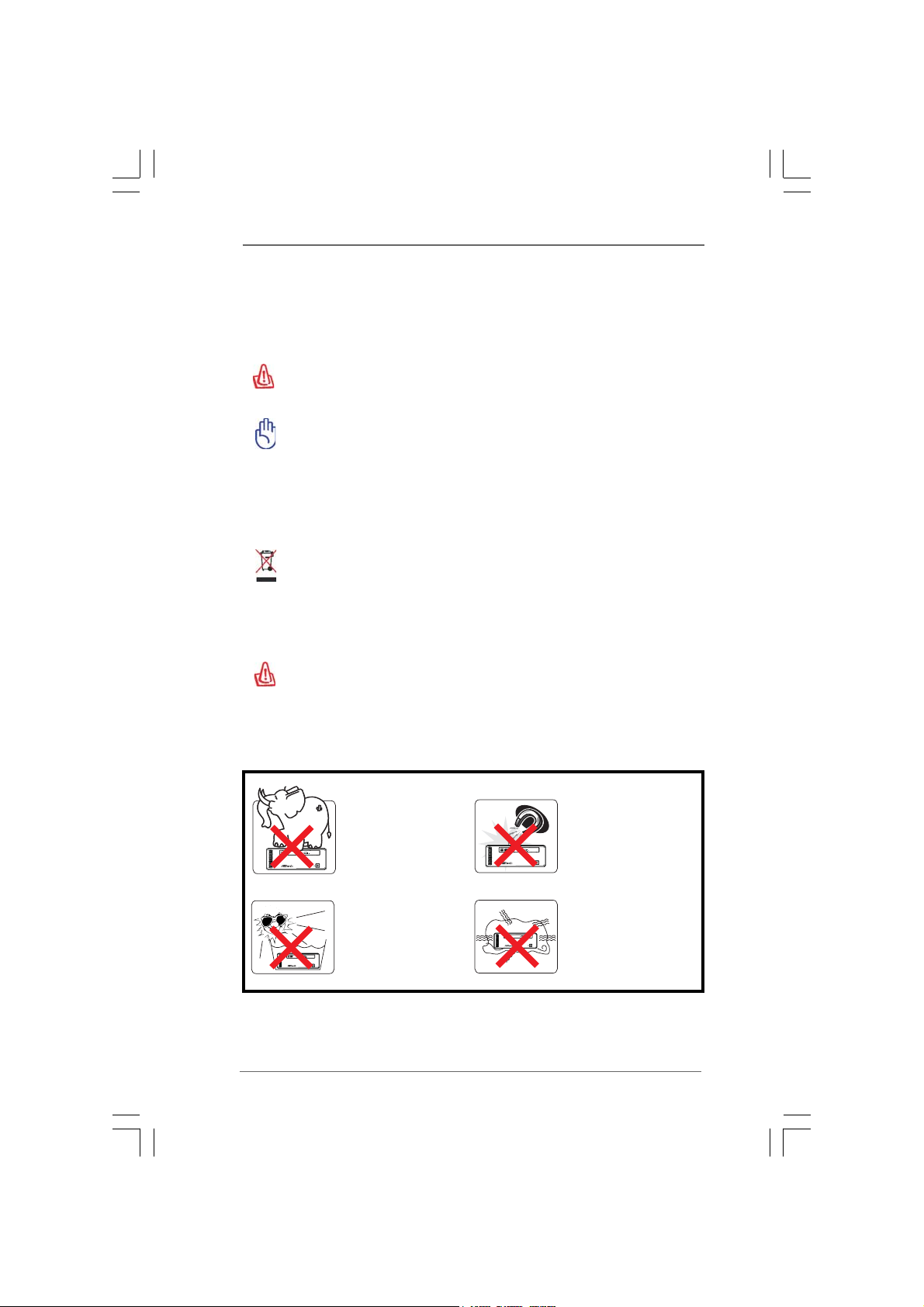
Installation Notices
44
4
44
Do not place this
product underneath
heavy loads or in an
unstable position.
Do not expose this
product to high levels
of direct sunlight,
high-humidity or wet
conditions.
Do not use or expose this
product around magnetic
fields as magnetic
interference may affect
the performance of the
product.
Do not block the air
vents to this product or
impede the airflow in any
way.

ContentsContents
Contents
ContentsContents
1 Introduction1 Introduction
1 Introduction
1 Introduction1 Introduction
1.1 Package Contents.......................................................... 7
1.2 Spec if ic at ion s ................................................................ 8
1.3 System Motherboard Components ............................... 9
1.4 Rear Panel Connections ................................................ 11
1.5 System Chassis............................................................. 12
1.6 Remote Controller .......................................................... 13
2 System Quick Installation2 System Quick Installation
2 System Quick Installation
2 System Quick Installation2 System Quick Installation
3 System Components Reinstallation3 System Components Reinstallation
3 System Components Reinstallation
3 System Components Reinstallation3 System Components Reinstallation
4 Installing Second HDD4 Installing Second HDD
4 Installing Second HDD
4 Installing Second HDD4 Installing Second HDD
5 Driver Installation5 Driver Installation
5 Driver Installation
5 Driver Installation5 Driver Installation
6 6
UTILITY MEMUUTILITY MEMU
6
UTILITY MEMU
6 6
UTILITY MEMUUTILITY MEMU
6.1 Instant Boot.................................................................... 23
6.1.1 Introduction .......................................................... 23
6.1.2 Installation ............................................................ 24
6.2 ASRock OC Tuner ......................................................... 26
6.2.1 Introduction .......................................................... 26
6.2.2 Installation ............................................................ 26
6.3 CyberLink DVD Suite free bundle (Trial version,
including PowerDVD, PowerDirector, etc) ................... 30
6.4 Symantec Norton AntiVirus Software free bundle
(Trial version) ................................................................ 32
6.5 THX TruStudio PRO Software free bundle................... 33
6.6 ASRock AIWI Utility ........................................................ 34
6.7 The best Apple charge companion - ASRock APP
Charger.......................................................................... 35
7 BIOS S7 BIOS S
7 BIOS S
7 BIOS S7 BIOS S
ETUP UTILITYETUP UTILITY
ETUP UTILITY
ETUP UTILITYETUP UTILITY
7.1 Introduction .................................................................... 3 6
7.1.1 BIOS Menu Bar .................................................... 36
7.1.2 Navigation Keys................................................... 3 7
7.2 Main Screen................................................................... 37
7.3 OC Tweaker Screen...................................................... 38
7.4 Advanced Screen ......................................................... 41
7.4.1 CPU Configuration................................................ 42
7.4.2 Chipset Configuration .......................................... 44
7.4.3 ACPI Configuration............................................... 45
7.4.4 Storage Configuration ......................................... 46
7.4.5 USB Configuration ............................................... 47
......................................................................................................
...................................................
......................................................................................................
..........................................................
.............................
..........................................................
........................
............
........................
....................................................................
..................................
....................................................................
....................................................................................
..........................................
....................................................................................
......................................................................................................
...................................................
......................................................................................................
......................................................................................
...........................................
......................................................................................
7 7
7
7 7
14 14
14
14 14
18 18
18
18 18
20 20
20
20 20
22 22
22
22 22
23 23
23
23 23
36 36
36
36 36
55
5
55

7.5 Hardware Health Event Monitoring Screen .................. 48
7.6 Boot Screen................................................................... 48
7.6.1 Boot Settings Configuration.................................. 49
7.7 Security Screen ............................................................ 50
7.8 Exit Screen .................................................................... 51
8 Software Support8 Software Support
8 Software Support
8 Software Support8 Software Support
8.1 Install Operating System ............................................... 52
8.2 Support CD Information ................................................. 52
8.2.1 Running Support CD ............................................ 52
8.2.2 Drivers Menu........................................................ 52
8.2.3 Utilities Menu ........................................................ 52
8.2.4 Contact Information.............................................. 52
......................................................................................
...........................................
......................................................................................
52 52
52
52 52
66
6
66
Chapter 1 IntroductionChapter 1 Introduction
Chapter 1 Introduction
Chapter 1 IntroductionChapter 1 Introduction
Thank you for purchasing ASRock Core 100 Series, a reliable product
produced under ASRock’s consistently stringent quality control. It delivers excellent
performance with robust design conforming to ASRock’s commitment to quality and
endurance.
In this manual, chapter 1 and 2 contain introduction of the hardware and step-bystep guide to the hardware installation. Chapter 3 and 4 contain the configuration
guide to BIOS setup and information of the Support CD.
Because the hardware specifications and the BIOS software might be
updated, the content of this manual will be subject to change without
notice. In case any modifications of this manual occur, the updated
version will be available on ASRock website without further notice. You
may find the latest VGA cards and CPU support lists on ASRock website
as well. ASRock website
If you require technical support related to this product, please visit our
website for specific information about the model you are using.
www.asrock.com/support/index.asp
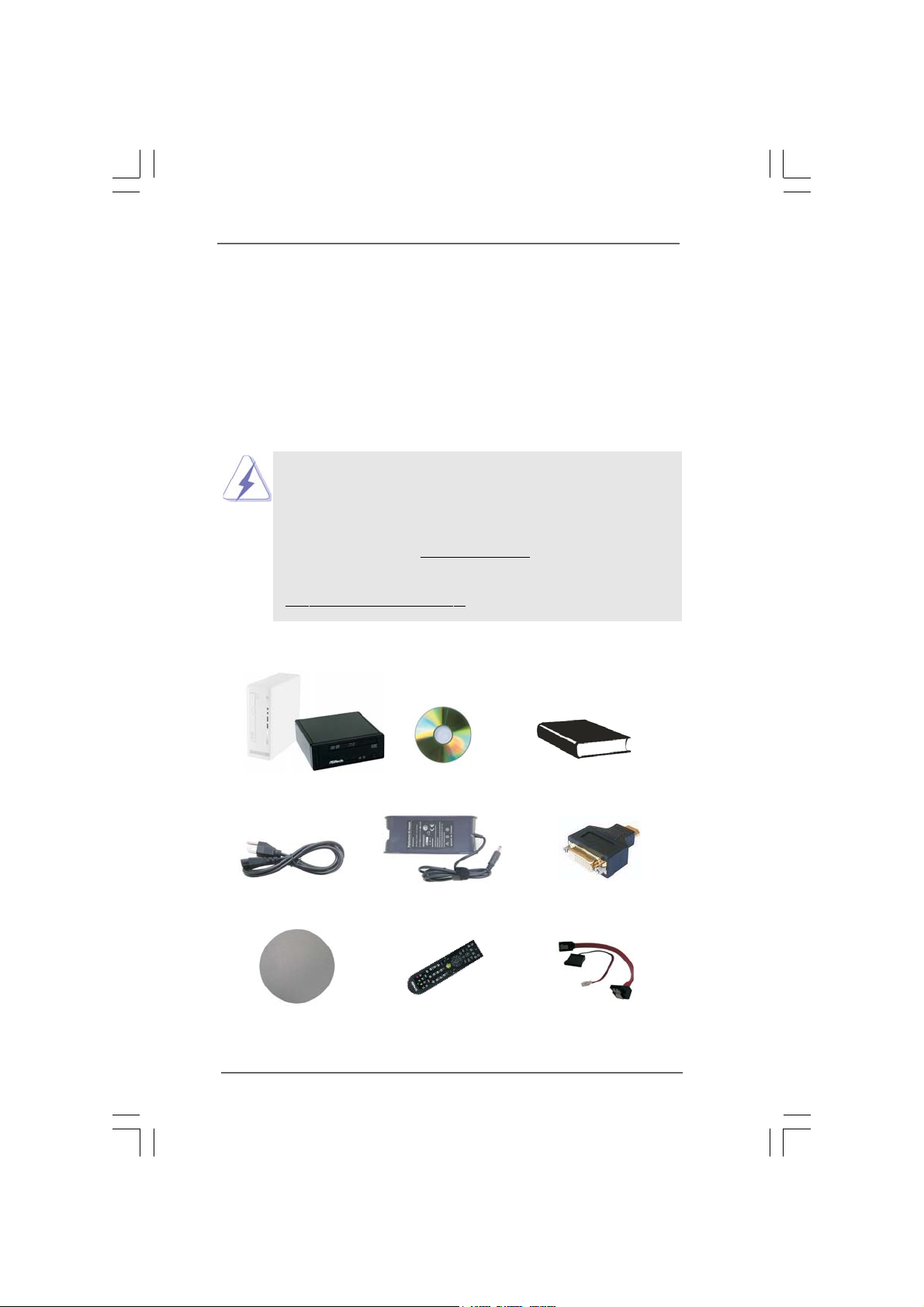
1.1 Package Contents1.1 Package Contents
1.1 Package Contents
1.1 Package Contents1.1 Package Contents
http://www.asrock.com
ASRock Core 100 Series ASRock Support CD ASRock Quick Start Guide
One AC Power Cord One AC/DC Adapter One HDMI to DVI Adapter
One Anti-Slip Pad Remote Controller SATA and Power Cables
(Core 100HT / Core 100HT-BD)
77
7
77

1.21.2
SpecificationsSpecifications
1.2
Specifications
1.21.2
SpecificationsSpecifications
* For barebone system, it may not contain memory, HDD or ODD.
Processor Support Intel® CoreTM i3/i5/i7 Mobile Processor
(Arrandale CPU)
Chipset Mobile Intel® HM55 Express chipset
*1
Memory Support DDR3 800/1066MHz,
2 x SO-DIMM slots, maximun up to 8GB
VGA Intel® HD Graphics
HDD 2.5” HDD, support second 2.5” HDD
DVD DVD Super Multi (Core 100 / Core 100HT)
BD Combo*2 (Core 100HT-BD)
Front I/O 2 x USB3.0, 1 x Microphone, 1 x Earphone
Rear I/O 1 x HDMI, 1 x D-Sub VGA, 6 x USB2.0, 1 x S/PDIF,
1 x eSATAII
Sound 7.0 Ch HD Audio with THX TruStudio Pro
*3
TM
LAN Gigabit LAN
WiFi 802.11b/g/n wireless LAN (Core 100HT / Core 100HT-BD)
Remote Support MCE function (Core 100HT / Core 100HT-BD)
Controller
Power 90W/19V Adapter
Dimension 195mm(W)x70mm(H)x186m(L)
Volume (liters) 2.5L
*1
Due to WinXP and PCH chipset (HM55) limitations, if you use WinXP, please disable the
BIOS option "USB2.0 Rate Matching Hub" to make USB devices work properly.
(For example, in the process of installing WinXP or using USB3.0 devices.)
*2
For CD-RW write type, only support 4x, 8x, 10x CD-RW DISC format.
*3
For eSATA function, Hot Plug function is supported in AHCI mode only. IDE mode does
not support Hot Plug function.
WARNING
Please realize that there is a certain risk involved with overclocking, including adjusting
the setting in the BIOS, or using the third-party overclocking tools. Overclocking may
affect your system stability, or even cause damage to the components and devices
of your system. It should be done at your own risk and expense. We are not
responsible for possible damage caused by overclocking.
88
8
88
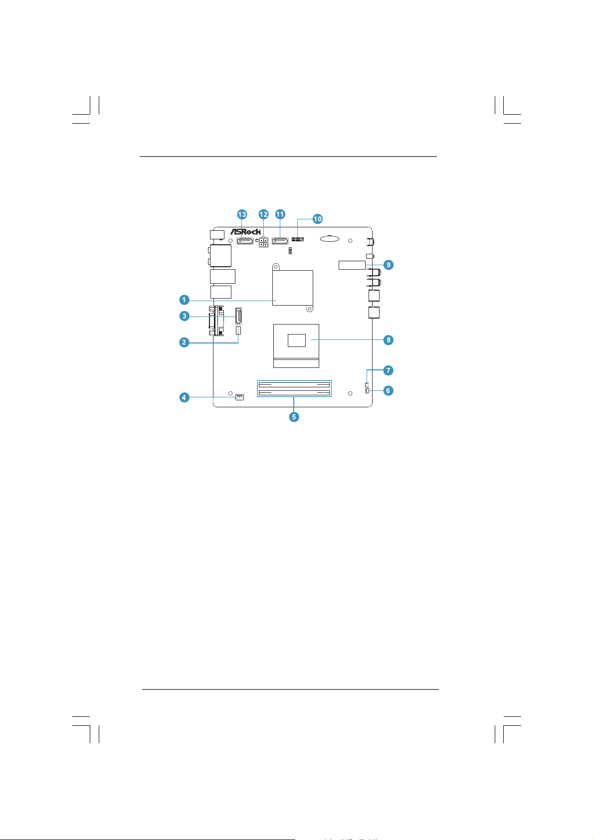
1.3 System Motherboard Components1.3 System Motherboard Components
1.3 System Motherboard Components
1.3 System Motherboard Components1.3 System Motherboard Components
DDR3_A1
DDR3_B1
Design inTaipei
PCIE1
FSB800
HM55-HT
EuP Ready
RoHS
1. Northbridge heatsink
2. J1 jumper: For second HDD SATA power cable
3. SATA connector: For second HDD SATA data cable
4. Fan connector
5. Memory socket
6. Fan connector
7. Infrared module header
8. CPU socket
9. Mini-PCI Express expansion slot: For WiFi module
10. Clear CMOS jumper
11. SATA connector: For ODD SATA data cable
12. ATX5V output power connector for slim ODD & 2.5” HDD
13. SATA connector: For HDD SATA data cable
99
9
99
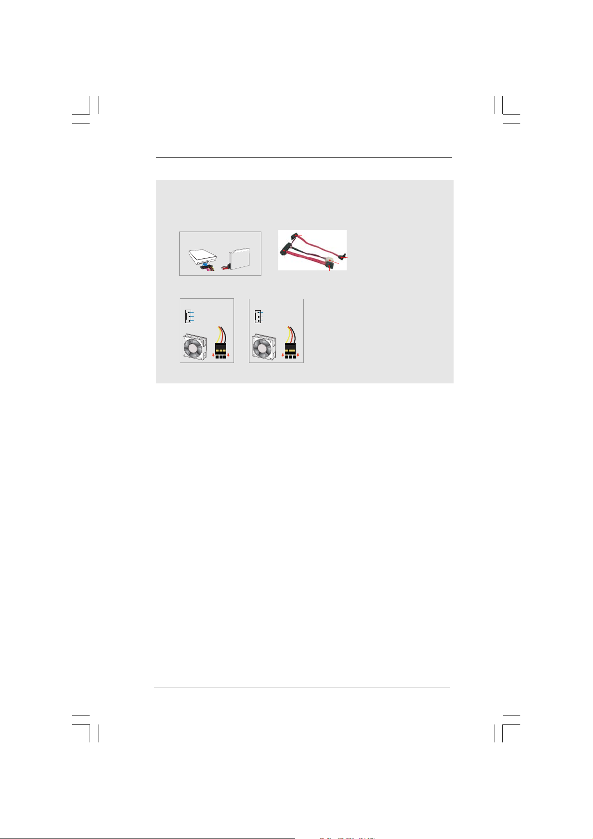
NOTE.
1. SATA and Power Connections
SATA &Power Connections
HDD
2. Fan Connection
Fan connector
Ground
+12V
Rotation
ODD
Connect toHDD
Fan connector
Ground
+5V
Rotation
Connect toODD
Connect toATX5V Power Connector(12)
Connect toSATA Connector (13)
Connect toSATA Connector (11)
item 4
item 6
1010
10
1010
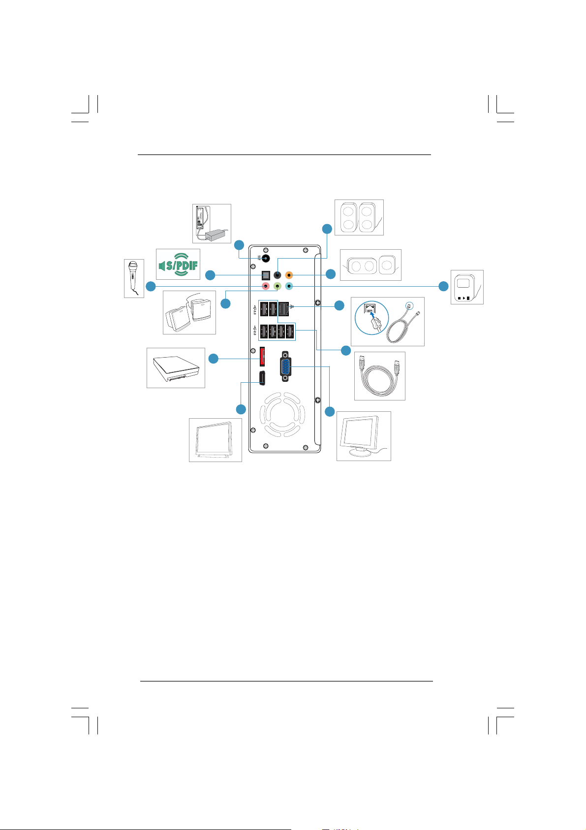
1.4 Rear Panel Connectinos1.4 Rear Panel Connectinos
1.4 Rear Panel Connectinos
1.4 Rear Panel Connectinos1.4 Rear Panel Connectinos
14
25
16
eSATA
15
S/PDIF
17
eSATAII
24
22
21
18
HDMI
20
SONY
19
14. DC-In jack
15. Optical S/PDIF Out port
16. Mic In (Pink): Microphone
17. Front L/R Out (Lime): Stereo speakers or headphones
18. eSATAII connector
19. Display (VGA) port
20. HDMI connector
21. USB2.0 ports: USB devices
22. LAN (RJ-45) port: Local Area Network
23. Line In (Blue) for 2/4/6 channel; Rear (Blue) for 8 channel
24. Center/LFE (Orange): Center / subwoofer speakers
25. Side port for side speakers
23
MP3
1111
11
1111
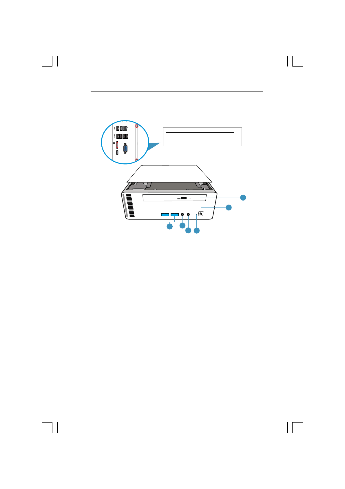
1.5 System Chassis1.5 System Chassis
HDMIeSATAII
1.5 System Chassis
1.5 System Chassis1.5 System Chassis
26. Optical Disc Drive
27. Power ON/OFF button with status indicator
28. Drive activity indicator
29. Earphone
30. Microphone
31. USB3.0 ports: USB devices
Opening the system chassis
1. Remove the screws on the backside.
2. Slide the top panel backwards.
27
30
31
29
28
26
1212
12
1212
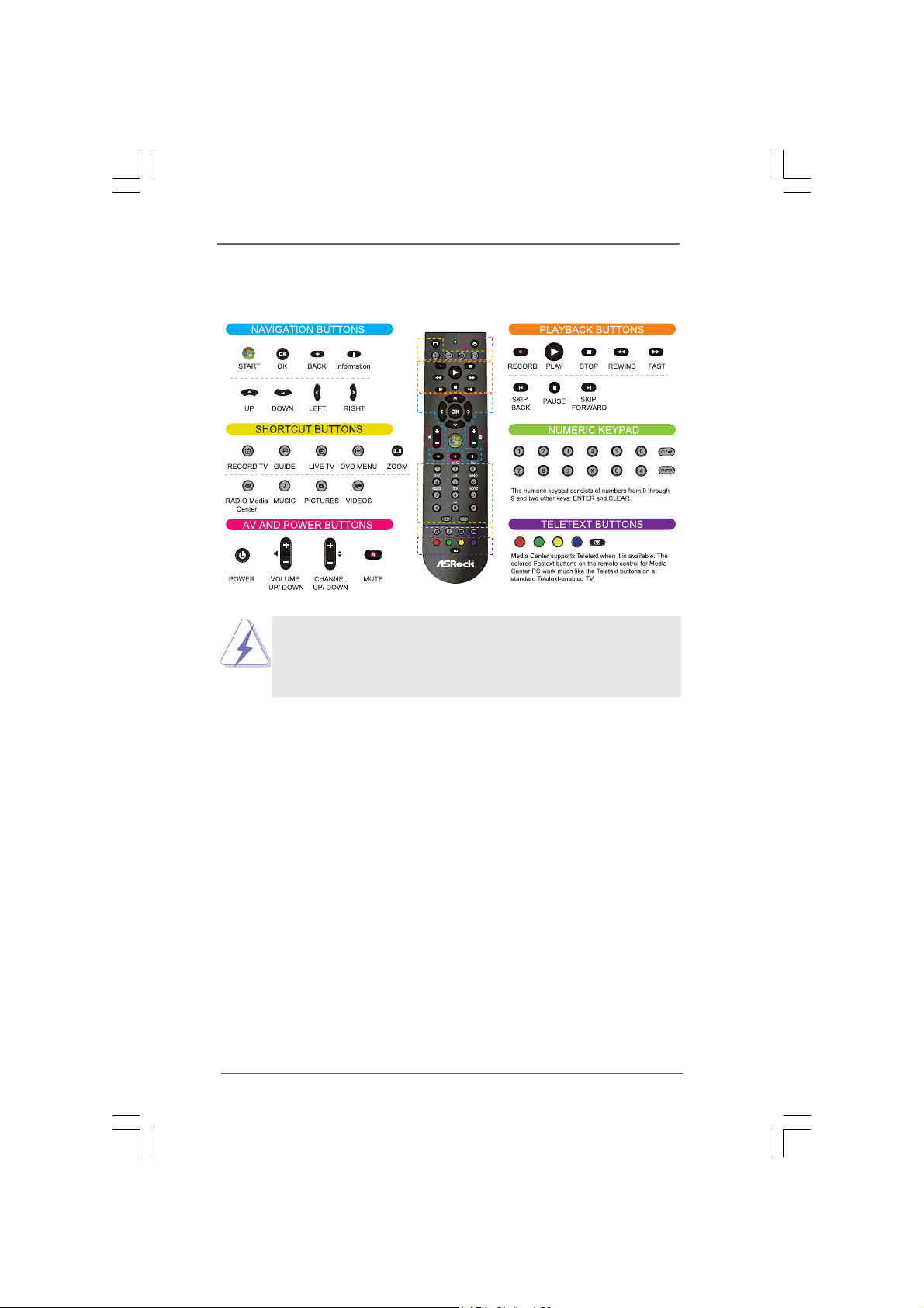
1.6 R1.6 R
emote Controller (Core 100HT / Core 100HTemote Controller (Core 100HT / Core 100HT
1.6 R
emote Controller (Core 100HT / Core 100HT
1.6 R1.6 R
emote Controller (Core 100HT / Core 100HTemote Controller (Core 100HT / Core 100HT
Some remote controller functions listed above are only available with the
relative hardware equipments. If the hardware equipments you adopt are not
compatible with the system, you are not allowed to use these functions. This
product is designed to meet MCE standards.
-BD)-BD)
-BD)
-BD)-BD)
1313
13
1313
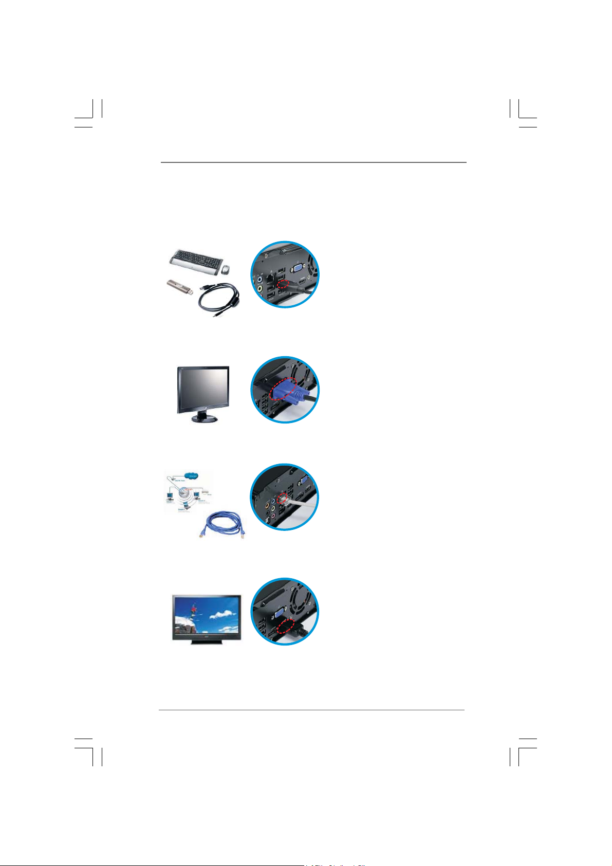
Chapter 2 System Quick InstallationChapter 2 System Quick Installation
Chapter 2 System Quick Installation
Chapter 2 System Quick InstallationChapter 2 System Quick Installation
1. Connecting USB Devices (USB2.0 Ports)
2. Connecting VGA Monitor (Display (VGA) Port)
3. Connecting the Network (LAN (RJ-45) Port)
4. Connecting HDMI Device (HDMI Port)
1414
14
1414
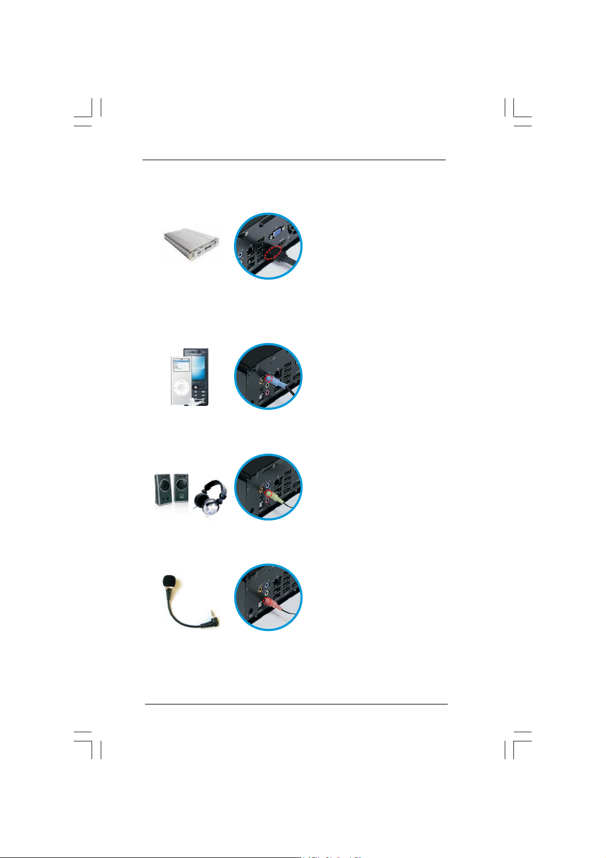
5. Connecting eSATA Device (eSATA Port)
6. Connecting External Audio Device
(Line In Port for 2/4/6 Channel; Rear Port for 8 Channel)
7. Connecting Stereo Speakers or Headphones (Front L/R Out Port)
8. Connecting Microphone (Mic In Port)
1515
15
1515
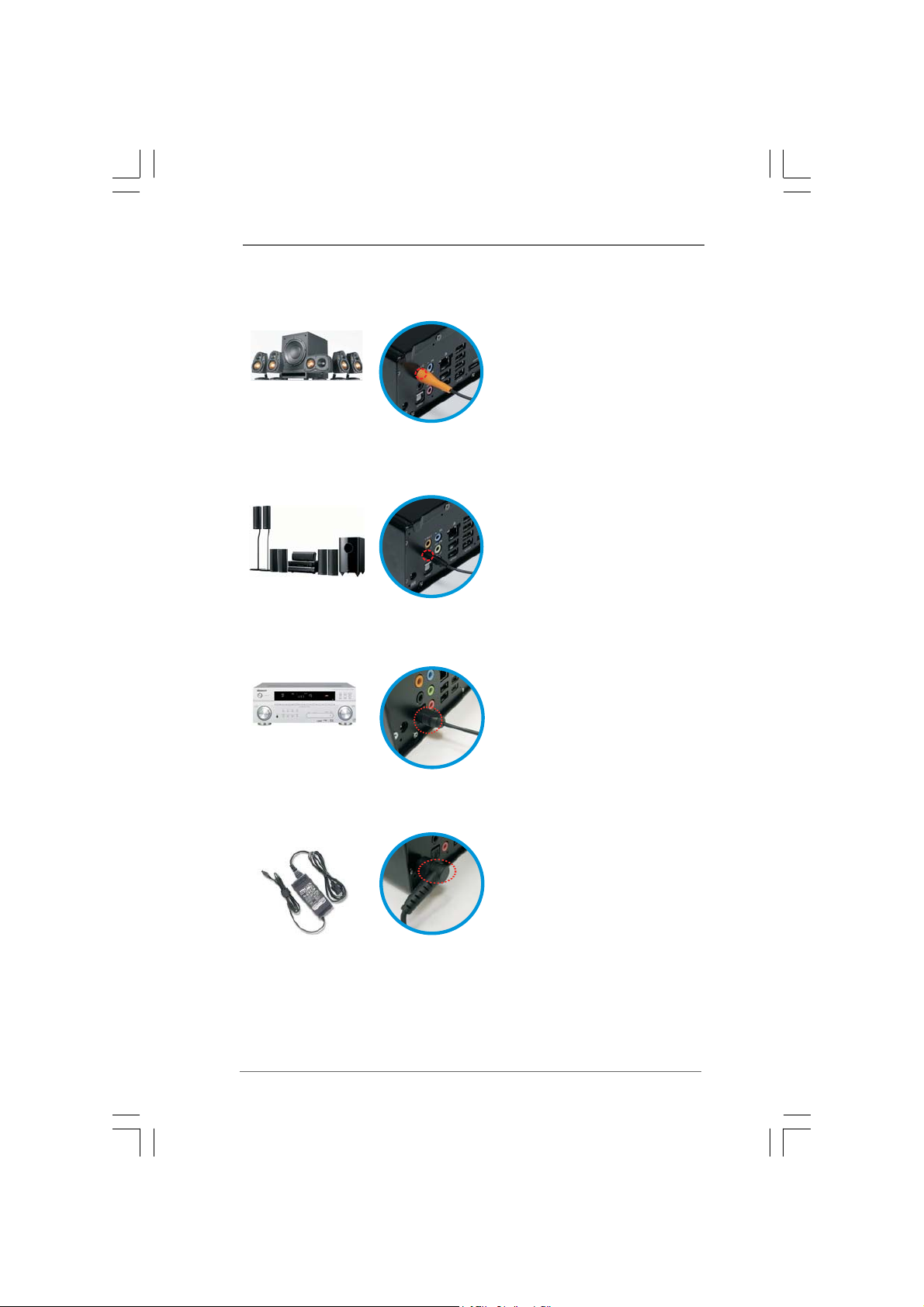
9. Connecting Center / Subwoofer Speakers (Center/LEF Port)
10. Connecting Side Speakers (Side Port for 4/6/8 Channel)
11. Connecting Optical Device (Optical S/PDIF Out Port)
12. Connecting Power (DC-In Jack Port)
1616
16
1616
 Loading...