

ASRock ConRoe945GZ-DVI User Manual

ConRoe945GZ-DVI
User Manual
Version 1.0
Published October 2006
Copyright©2006 ASRock INC. All rights reserved.
11
1
11

Copyright Notice:Copyright Notice:
Copyright Notice:
Copyright Notice:Copyright Notice:
No part of this manual may be reproduced, transcribed, transmitted, or translated in
any language, in any form or by any means, except duplication of documentation by
the purchaser for backup purpose, without written consent of ASRock Inc.
Products and corporate names appearing in this manual may or may not be registered trademarks or copyrights of their respective companies, and are used only for
identification or explanation and to the owners’ benefit, without intent to infringe.
Disclaimer:Disclaimer:
Disclaimer:
Disclaimer:Disclaimer:
Specifications and information contained in this manual are furnished for informational use only and subject to change without notice, and should not be constructed
as a commitment by ASRock. ASRock assumes no responsibility for any errors or
omissions that may appear in this manual.
With respect to the contents of this manual, ASRock does not provide warranty of
any kind, either expressed or implied, including but not limited to the implied warranties or conditions of merchantability or fitness for a particular purpose.
In no event shall ASRock, its directors, officers, employees, or agents be liable for
any indirect, special, incidental, or consequential damages (including damages for
loss of profits, loss of business, loss of data, interruption of business and the like),
even if ASRock has been advised of the possibility of such damage s arising from any
defect or error in the manual or product.
This device complies with Part 15 of the FCC Rules. Operation is subject to the
following two conditions:
(1) this device may not cause harmful interference, and
(2) this device must accept any interference received, including interference that
may cause undesired operation.
CALIFORNIA, USA ONLY
The Lithium battery adopted on this motherboard contains Perchlorate, a toxic
substance controlled in Perchlorate Best Management Practices (BMP) regulations
passed by the California Legislature. When you discard the Lithium battery in
California, USA, please follow the related regulations in advance.
“Perchlorate Material-special handling may apply, see
www.dtsc.ca.gov/hazardouswaste/perchlorate”
ASRock Website: http://www.asrock.com
22
2
22

ContentsContents
Contents
ContentsContents
1 Introduction1 Introduction
1 Introduction
1 Introduction1 Introduction
1.1 Package Contents.......................................................... 5
1.2 Specifications................................................................ 6
1.3 Minimum Hardware Requirement Table for Windows
VistaTM Premium and Basic Logo.................................. 9
1.4 Supported PCI Express VGA Card List for AGI Express
Slot (PCI Express x4) ................................................... 10
1.5 Motherboard Layout ..................................................... 11
1.6 ASRock DVI I/O Plus ....................................................... 12
2 Installation2 Installation
2 Installation
2 Installation2 Installation
2.1 Screw Holes ................................................................. 13
2.2 Pre-installation Precautions........................................... 1 3
2.3 CPU Installation .............................................................. 14
2.4 Installation of Heatsink and CPU fan ............................. 16
2.5 Installation of Memory Modules (DIMM)......................... 17
2.6 Expansion Slots (PCI, HDMR, and AGI Express Slots) ....... 18
2.7 Multi Monitor Feature ..................................................... 19
2.8 Jumpers Setup .............................................................. 20
2.9 Onboard Headers and Connectors .............................. 21
2.10 SATAII Hard Disk Setup Guide ....................................... 25
2.11 Serial ATA (SATA) / Serial ATAII (SATAII) Hard Disks
Installation ...................................................................... 26
2.12 Driver Installation Guide .............................................. 26
2.13 HDMR Card and Driver Installation .............................. 26
2.14 Untied Overclocking Technology ................................... 26
3 BIOS S3 BIOS S
3 BIOS S
3 BIOS S3 BIOS S
ETUP UTILITYETUP UTILITY
ETUP UTILITY
ETUP UTILITYETUP UTILITY
3.1 Introduction .................................................................... 27
3.1.1 BIOS Menu Bar .................................................... 27
3.1.2 Navigation Keys................................................... 28
3.2 Main Screen................................................................... 28
3.3 Advanced Screen ......................................................... 28
3.3.1 CPU Configuration................................................ 29
3.3.2 Chipset Configuration .......................................... 31
3.3.3 ACPI Configuration............................................... 33
3.3.4 IDE Configuration ................................................. 34
3.3.5 PCIPnP Configuration ........................................... 36
3.3.6 Floppy Configuration ........................................... 37
3.3.7 Super IO Configuration ........................................ 37
3.3.8 USB Configuration ............................................... 3 8
......................................................................................................
...................................................
......................................................................................................
............................................................................................................
......................................................
............................................................................................................
......................................................................................
...........................................
......................................................................................
5 5
5
5 5
®
13 13
13
13 13
27 27
27
27 27
33
3
33

3.4 Hardware Health Event Monitoring Screen .................. 39
3.5 Boot Screen................................................................... 40
3.5.1 Boot Settings Configuration.................................. 40
3.6 Security Screen ............................................................ 41
3.7 Exit Screen .................................................................... 42
4 Software Support4 Software Support
4 Software Support
4 Software Support4 Software Support
4.1 Install Operating System ............................................... 43
4.2 Support CD Information ................................................. 43
4.2.1 Running Support CD ............................................ 43
4.2.2 Drivers Menu........................................................ 43
4.2.3 Utilities Menu ........................................................ 4 3
4.2.4 “LGA 775 CPU Installation Live Demo” Progra m .. 43
4.2.5 Contact Information.............................................. 43
......................................................................................
...........................................
......................................................................................
43 43
43
43 43
44
4
44
Chapter 1 IntroductionChapter 1 Introduction
Chapter 1 Introduction
Chapter 1 IntroductionChapter 1 Introduction
Thank you for purchasing ASRock ConRoe945GZ-DVI motherboard, a reliable
motherboard produced under ASRock’s consistently stringent quality control. It delivers excellent performance with robust design conforming to ASRock’s commitment to quality and endurance.
In this manual, chapter 1 and 2 contain introduction of the motherboard and step-bystep guide to the hardware installation. Chapter 3 and 4 contain the configuration
guide to BIOS setup and information of the Support CD.
Because the motherboard specifications and the BIOS software might be
updated, the content of this manual will be subject to change without
notice. In case any modifications of this manual occur, the updated
version will be available on ASRock website without further notice. You
may find the latest VGA cards and CPU support lists on ASRock website
as well. ASRock website
1.1 Package Contents1.1 Package Contents
1.1 Package Contents
1.1 Package Contents1.1 Package Contents
ASRock ConRoe945GZ-DVI Motherboard
(Micro ATX Form Factor: 9.6-in x 8.8-in, 24.4 cm x 22.4 cm)
ASRock ConRoe945GZ-DVI Quick Installation Guide
ASRock ConRoe945GZ-DVI Support CD
(including LGA 775 CPU Installation Live Demo)
One 80-conductor Ultra AT A 66/100 IDE Ribbon Cable
One Ribbon Cable for a 3.5-in Floppy Drive
One Serial ATA (SATA) Data Cable (Optional)
One Serial ATA (SATA) HDD Power Cable (Optional)
One ASRock DVI I/O Plus I/O Shield
One COM Port Bracket
One HDMR Card (Optional)
http://www.asrock.com
55
5
55

1.21.2
SpecificationsSpecifications
1.2
Specifications
1.21.2
SpecificationsSpecifications
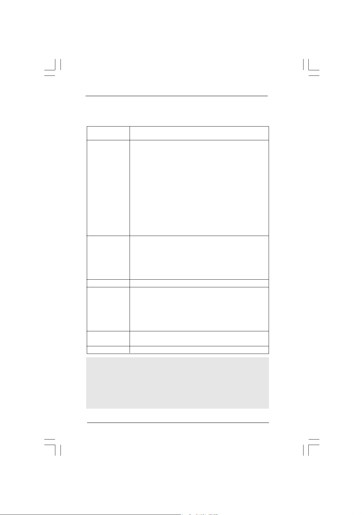
Platform - Micro ATX Form Factor: 9.6-in x 8.8-in, 24.4 cm x 22.4 cm
CPU - LGA 775 for Intel® CoreTM 2 Duo / Pentium® D / Pentium® 4 /
Celeron® D processors (see CAUTION 1)
- FSB 800/533 MHz
- Supports Hyper-Threading Technology (see CAUTION 2)
- Supports Untied Overclocking Technology (see CAUTION 3)
- Supports EM64T CPU
Chipset - Northbridge: Intel® 945GZ
- Southbridge: Intel® ICH7
Memory - Dual Channel DDRII Memory Technology (see CAUTION 4)
- 2 x DDRII DIMM slots
- Support DDRII533
- Max. capacity: 2GB
Hybrid Booster - CPU Frequency Stepless Control (see CAUTION 5)
- ASRock U-COP (see CAUTION 6)
- Boot Failure Guard (B.F.G.)
Expansion Slot - 1 x AGI Express slot (PCI Express x4) (see CAUTION 7)
- 3 x PCI slots
- 1 x HDMR slot
Graphics - Intel® Graphics Media Accelerator 950
- Pixel Shader 2.0, DirectX 9.0
- Max. shared memory 224MB
- Supports DVI-D and D-Sub ports: Either DVI-D or D-Sub port
can be chosen for display at the same time
Audio - 7.1 CH Windows® VistaTM Premium Level HD Audio
(ALC888 Audio Codec)
LAN - Realtek PCI LAN 8101L
- Speed: 10/100 Ethernet
- Supports Wake-On-LAN
Rear Panel I/O ASRock DVI I/O Plus
- 1 x PS/2 Mouse Port
- 1 x PS/2 Keyboard Port
- 1 x VGA/D-Sub Port
- 1 x VGA/DVI-D Port
- 1 x Parallel Port (ECP/EPP Support)
- 4 x Ready-to-Use USB 2.0 Ports
- 1 x RJ-45 LAN Port
66
6
66
- HD Audio Jack: Side Speaker/Rear Speaker/Central/Bass/
Line in/Front Speaker/Microphone (see CAUTION 8)
Connector - 4 x SATAII 3.0 Gb/s connectors (No Support for RAID and
“Hot Plug” functions) (see CAUTION 9)
- 1 x ATA100 IDE connector (supports 2 x IDE devices)
- 1 x Floppy connector
- 1 x IR header
- 1 x COM port header
- CPU/Chassis FAN connector
- 20 pin ATX power connector
- 4 pin 12V power connector
- CD in header
- Front panel audio connector
- 2 x USB 2.0 headers (support 4 USB 2.0 ports)
(see CAUTION 10)
BIOS Feature - 4Mb AMI BIOS
- AMI Legal BIOS
- Supports “Plug and Play”
- ACPI 1.1 Compliance W ake Up Events
- Supports jumperfree
- AMBIOS 2.3.1 Support
Support CD - Drivers, Utilities, AntiVirus Software (Trial Version)
Hardware - CPU Temperature Sensing
Monitor - Chassis Temperature Sensing
- CPU Fan Tachometer
- Chassis Fan Tachometer
- CPU Quiet Fan
- Voltage Monitoring: +12V, +5V, +3.3V, CPU Vcore
OS - Microsoft® Windows® 2000/XP/XP 64-bit/VistaTM/
VistaTM 64-bit compliant (see CAUTION 11)
Certifications - FCC, CE, WHQL
WARNING
Please realize that there is a certain risk involved with overclocking, including adjusting
the setting in the BIOS, applying Untied Overclocking Technology, or using the thirdparty overclocking tools. Overclocking may affect your system stability, or even
cause damage to the components and devices of your system. It should be done at
your own risk and expense. We are not responsible for possible damage caused by
overclocking.
77
7
77

CAUTION!
1. This motherboard supports FSB800-CPU. If you plan to adopt CoreTM 2
Duo CPU on this motherboard, you can only adopt Conroe 800 E4XXX
processors.
2. About the setting of “Hyper Threading Technology”, please check page 30.
3. This motherboard supports Untied Overclocking Technology. Please read
“Untied Overclocking Technology” on page 26 for details.
4. This motherboard supports Dual Channel Memory Technology. Before you
implement Dual Channel Memory Technology, make sure to read the
installation guide of memory modules on page 17 for proper installation.
5. Although this motherboard offers stepless control, it is not recommended
to perform over-clocking. Frequencies other than the recommended CPU
bus frequencies may cause the instability of the system or damage the
CPU.
6. While CPU overheat is detected, the system will automatically shutdown.
Before you resume the system, please check if the CPU fan on the
motherboard functions properly and unplug the power cord, then plug it
back again. To improve heat dissipation, remember to spray thermal
grease between the CPU a nd the heatsink when you in stall the PC system.
7. For the information of the compatible PCI Express VGA cards, please
refer to the “Supported PCI Express VGA Card List for AGI Express Slot
(PCI Express x4)” on page 10. For the proper installation of PCI Express
VGA card, please refer to the installation guide on page 18.
8. For microphone input, this motherboard supports both stereo and mono
modes. For audio output, this motherboard supports 2-channel, 4-channel,
6-channel, and 8-channel modes. Please check the table on page 12 for
proper connection.
9. Before installing SA TAII hard disk to SA TAII connector, please rea d the “SATAII
Hard Disk Setup Guide” on page 25 to adjust your SATAII hard disk drive to
SATAII mode. You can also connect SATA hard disk to SATAII connector
directly.
10. Power Management for USB 2.0 works fine under Microsoft® Windows
VistaTM / XP 64-bit / XP SP1 or SP2 / 2000 SP4.
11. Microsoft
®
Windows® VistaTM driver is not ready yet. We will update it to our
website in the future. Please visit our website for Microsoft
®
Windows® Vista
driver and related information.
ASRock website
http://www.asrock.com
®
TM
88
8
88

1.31.3
Minimum Hardware RMinimum Hardware R
1.3
Minimum Hardware R
1.31.3
Minimum Hardware RMinimum Hardware R
TMTM
TM
TMTM
VistaVista
Vista
VistaVista
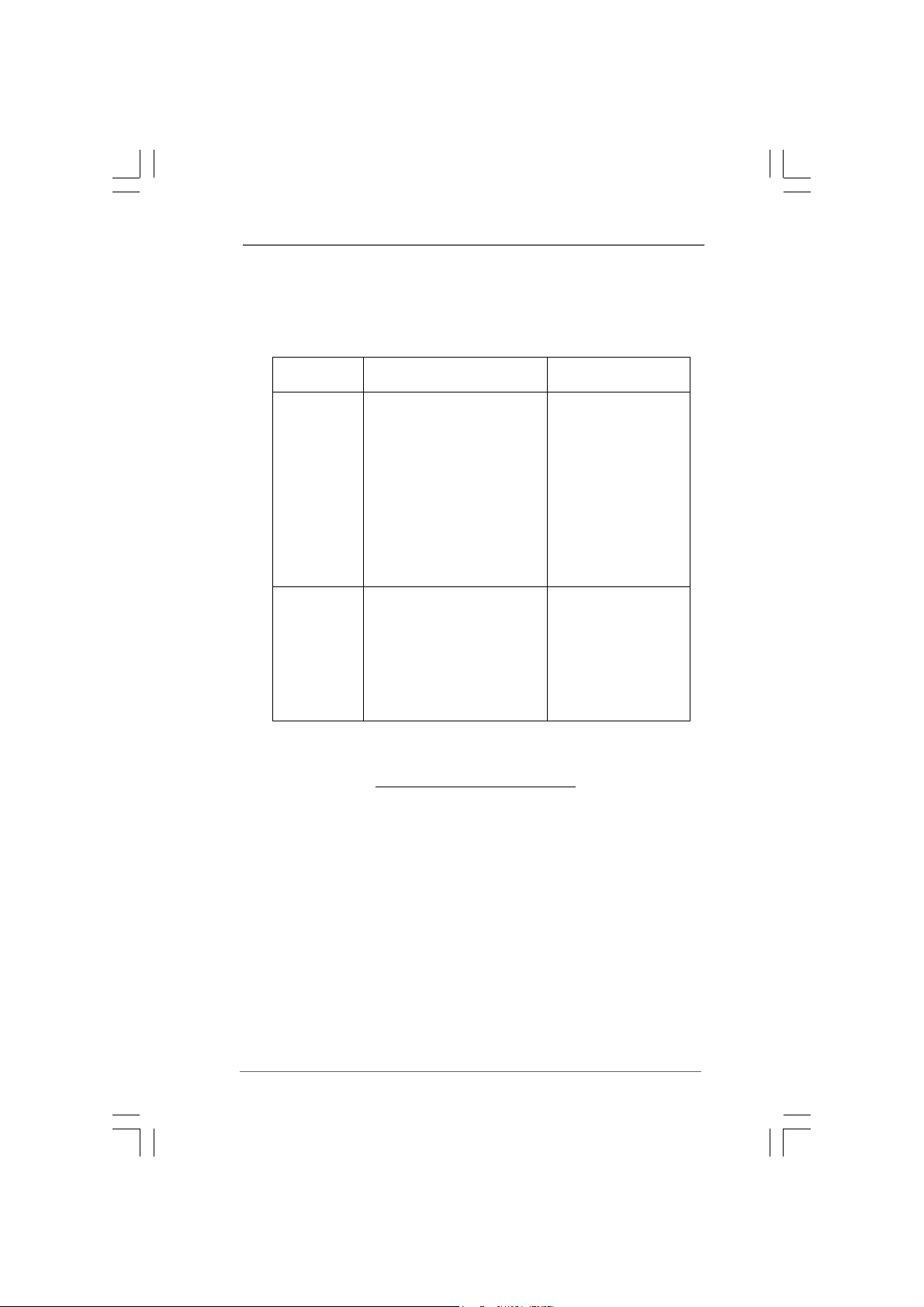
For system integrators and users who purchase this motherboard and
plan to submit Windows® VistaTM Premium and Basic logo, please follow the
below table for minimum hardware requirement.
CPU Celeron D 326
Memory 512MB x 2 Dual Channel (Premium)
* If you plan to use external graphics card on this motherboard, please refer to
Premium Discrete requirement at http://www.asrock.com
Premium and Basic Logo Premium and Basic Logo
Premium and Basic Logo
Premium and Basic Logo Premium and Basic Logo
512MB Single Channel (Ba sic)
256MB x 2 Dual Channel (Basic)
equirement Tequirement T
equirement T
equirement Tequirement T
able for Wable for W
able for W
able for Wable for W
indowsindows
indows
indowsindows
®®
®
®®
99
9
99
1.41.4
Supported PCI Express VGA Card List for AGISupported PCI Express VGA Card List for AGI
1.4
Supported PCI Express VGA Card List for AGI
1.41.4
Supported PCI Express VGA Card List for AGISupported PCI Express VGA Card List for AGI
Express Slot (PCI Express x4)Express Slot (PCI Express x4)
Express Slot (PCI Express x4)
Express Slot (PCI Express x4)Express Slot (PCI Express x4)
(for Windows® 2000/XP/XP 64-bit/VistaTM)
Graphics Chip Model Name Chipset Name
Vendor
NVIDIA ASUS EN5750/A GeForce 5750
ASUS EN5900 GeForce 5900
ASUS EN6600GT GeForce 6600
ASUS Extreme N6800GT GeForce 6800GT
ASUS EN7600GT/2DHT GeForce 7600GT
ALBATRON PC6600GT GeForce 6600GT
GIGABYTE GV -NX62128D GeForce 6200
Inno3D GeForce6600LE GeForce 6600LE
LEADTEK PX6500 TDH GeForce 6500
LEADTEK PX7300GS T DH GeForce 7300 GS
LEADTEK PX7300LE-TDH GeForce 7300 LE
SPARKLE GeFORCE 6200TC GeForce 6200TC
ATI ASUS EAX700Pro Radeon 700Pro
ASUS EAX1300PRO/TD/256M/A Radeon X1300 PRO
ASUS EAX1900XT/2DHTV Radeon X1900XT
GECUBE Radeon X850XT 256M RADEON X850XT
MSI RX300SE-TD128E Radeon X300SE
MSI RX1300GPRO-TD256E RADEON X1300Pro
MSI RX1600GPRO-TD256E RADEON X1600Pro
MSI RX1600XT-T2D256EZ RADEON X1600XT
1010
10
1010
For the latest updates of the supported PCI Express VGA card list for AGI Express
slot (PCI Express x4), please visit our website for details.
ASRock website:
http://www.asrock.com/support/index.htm
1.51.5
Motherboard LayoutMotherboard Layout
1.5
Motherboard Layout
1.51.5
Motherboard LayoutMotherboard Layout
28
27
26
25
Keyboard
Mouse
PS2
VGA1
PARALLEL PORT
DVI_CON1
USB2.0
Top:
T:USB0
RJ-45
B:USB1
USB2.0
T: US B2
B:USB3
Center:
REAR SPK
Bottom:
CTR BASS
Bottom:
MIC IN
Center:
FRONT
AUDIO
CODEC
PS2
Top:
SIDE SPK
Top:
LINE IN
LAN
CD1
1
HD_AUDIO1
24
1
1
PS2_USB_PWR1
ATX12V1
PCI
2
ATXPWR1
7.1CH HD
HDMR1
23
22.4cm (8.8 in)
AGI_EXPRESS1
USB2.0
PCI1
RoHS
PCI2
PCI3
FLOPPY1
PCI
EXPRESS
22
3
Intel
945GZ
Chipset
SATAII
DVI
1
5
4
CPU_FAN1
FSB800
Dual Channel
Conroe
Dual CoreCPU
Presler
ConRoe945GZ-DVI
Intel
ICH7
USB67
USB45
1
21
20
18
19
6
DDRII_1 (64/72bit, 240-pin module)
CMOS
Battery
SATAII_3
SATAII_1
4Mb
BIOS
17
7
IR1
1
DDRII_2 (64/72bit, 240-pin module)
IDE1
SPEAKER1
1
PLED PWRBTN
1
Super
SATAII_4
SATAII_2
PANEL1
HDLED RESET
16
I/O
CLRCMOS1
CHA_FAN1
DDRII533
COM1
1
24.4cm (9.6 in)
10
11
12
13
14
15
8
9
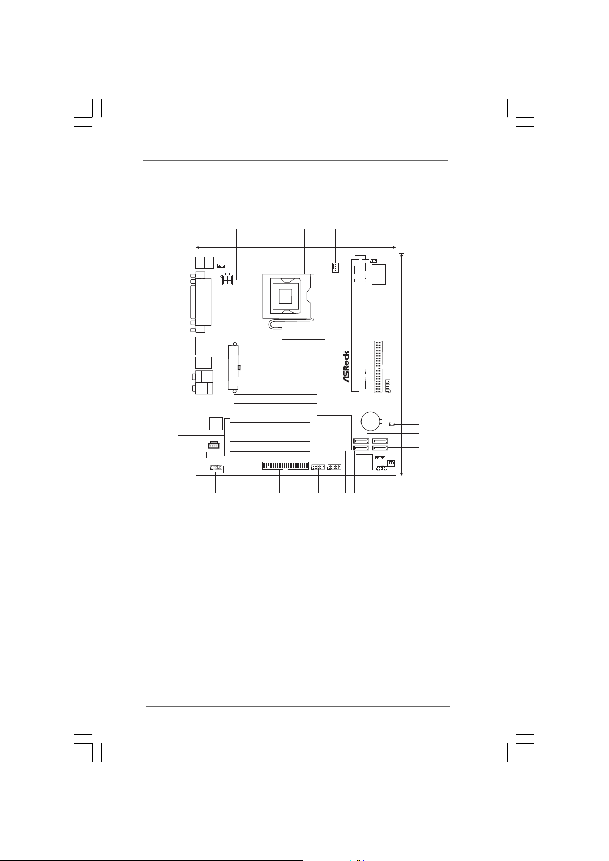
1 PS2_USB_PWR1 Jumper 15 Chassis Fan Connector (CHA_FAN1)
2 A TX 12V Connector (A TX12V1) 16 System Panel He ader (P ANEL1)
3 775-Pin CPU Socket 17 BIOS FWH Chip
4 North Bridge Controller 1 8 Primary SA T AII Connector (SA T AII_1; Red)
5 CPU Fan Connector (CPU_FAN1) 19 South Bridge Controller
6 2 x 240-pin DDRII DIMM Slots 20 USB 2.0 Header (USB67, Blue)
(Dual Channel: DDRII_1, DDRII_2; Yellow) 21 USB 2.0 Header (USB45, Blue)
7 Infrared Module Header (IR1) 22 Floppy Connector (FLOPPY1)
8 IDE1 Connector (IDE1, Blue) 23 HDMR Slot (HDMR1)
9 Serial Port Connector (COM1) 24 Front Panel Audio Header (HD_AUDIO1)
10 Clear CMOS Jumper (CLRCMOS1) 25 Internal Audio Connector: CD1 (Black)
11 Third SAT AII Connector (SA T AII_3; Ora nge) 26 PCI Slots (PCI1- 3)
12 Fourth SAT AII Connector (SATAII_4; Orange) 27 AGI Express Slot (PCI Express x4)
13 Secondary SATAII Conne ctor (SA T AII_2; Red) 28 ATX Power Connector (ATXPWR1)
14 Chassis Speaker Header (SPEAKER 1)
1111
11
1111
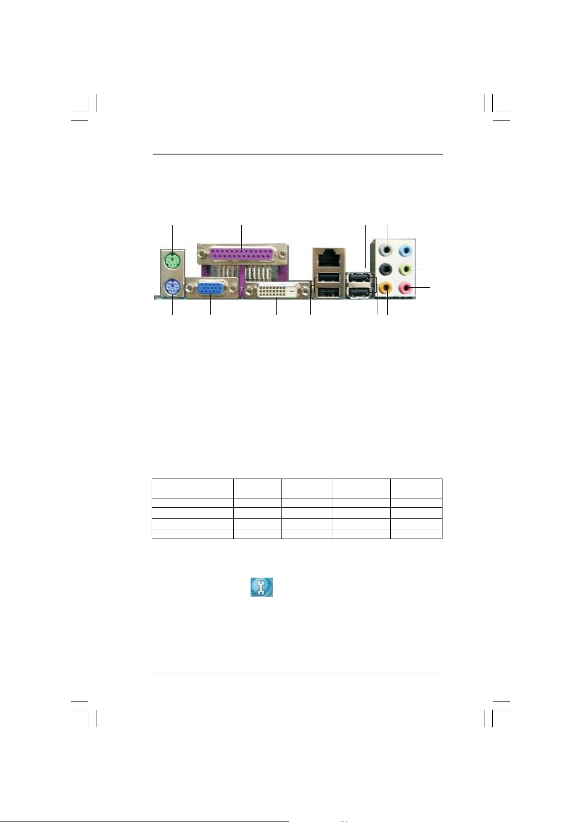
1.61.6
ASRock DVI I/O PlusASRock DVI I/O Plus
1.6
ASRock DVI I/O Plus
1.61.6
ASRock DVI I/O PlusASRock DVI I/O Plus
1
2
3
4
5
6
7
8
1314
1 PS/2 Mouse Port (Green) 8 Microphone (Pink)
2 Parallel Port 9 Central / Bass (Orange)
3 RJ-45 Port 10 USB 2.0 Ports (USB23)
4 Rear Speaker (Black) 11 USB 2.0 Ports (USB01)
5 Side Speaker (Gray) 12 V GA/D VI-D Port
6 Line In (Light Blue) 13 VGA/D-Sub Port
*7 Front Speaker (Lime) 14 PS/2 Keyboard Port (Purple)
12
11
* If you use 2-channel speaker, please connect the speaker’s plug into “Front Speaker Jack”. See
the table below for connection details in accordance with the type of speaker you use.
TABLE for Audio Output Connection
Audio Output Channels Front Speaker Rear Speaker Central / Bass Side Speaker
(No. 7) (No. 4) (No. 9) (No. 5)
2 V -- -- -4VV---6VVV-8VVVV
10
9
* To enable Multi-Streaming function, you need to connect a front panel audio cable to the front
panel audio header. After restarting your computer, you will find “Mixer” tool on your system.
Please select “Mixer ToolBox” , click “Enable playback multi-streaming”, and click
“ok”. Choose “2CH”, “4CH”, “6CH”, or “8CH” and then you are allowed to select “Realtek HDA
Primary output” to use Rear Speaker, Central/Bass, and Front Speaker, or select “Realtek HDA
Audio 2nd output” to use front panel audio.
1212
12
1212
Chapter 2 InstallationChapter 2 Installation
Chapter 2 Installation
Chapter 2 InstallationChapter 2 Installation
ConRoe945GZ-DVI is a Micro ATX form factor (9.6-in x 8.8-in, 24.4 cm x 22.4 cm)
motherboard. Before you install the motherboard, study the configuration of your
chassis to ensure that the motherboard fits into it.
Make sure to unplug the power cord before installing or removing the
motherboard. Failure to do so may cause physical injuries to you and
damages to motherboard components.
2.1 Screw Holes2.1 Screw Holes
2.1 Screw Holes
2.1 Screw Holes2.1 Screw Holes
Place screws into the holes indicated by circles to secure the motherboard to the
chassis.
Do not over-tighten the screws! Doing so may damage the motherboard.
2.2 Pre-installation Precautions2.2 Pre-installation Precautions
2.2 Pre-installation Precautions
2.2 Pre-installation Precautions2.2 Pre-installation Precautions
Take note of the following precautions before you install motherboard components
or change any motherboard settings.
1. Unplug the power cord from the wall socket before touching any component.
2. To avoid damaging the motherboard components due to static electricity, NEVER
place your motherboard directly on the carpet or the like. Also remember to use
a grounded wrist strap or touch a safety grounded object before you handle
components.
3. Hold components by the edges and do not touch the ICs.
4. Whenever you uninstall any component, place it on a grounded antistatic pad or
in the bag that comes with the component.
Before you install or remove any component, ensure that the power is
switched off or the power cord is detached from the power supply.
Failure to do so may cause severe damage to the motherboard, peripherals,
and/or components.
1313
13
1313
 Loading...