

ASRock C226 WS Owner's Manual

C226 WS
User Manual
Version 1.0
Published June 2013
Copyright©2013 ASRock INC. All rights reserved.
1

Version 1.0
Published June 2013
Copyright©2013 ASRock INC. All rights reser ved.
Copyright Notice:
No part of this documentation may be reproduced, transcribed, transmitted, or
translated in any language, in any form or by any means, except duplication of
documentation by the purchaser for backup purpose, without written consent of
ASRock Inc.
Products and corporate names appearing in this documentation may or may not
be registered trademarks or copyrights of their respective companies, and are used
only for identication or explanation and to the owners’ benet, without intent to
infringe.
Disclaimer:
Specications and information contained in this documentation are furnished for
informational use only and subject to change without notice, and should not be
constructed as a commitment by ASRock. ASRock assumes no responsibility for
any errors or omissions that may appear in this documentation.
With respect to the contents of this documentation, ASRock does not provide
warranty of any kind, either expressed or implied, including but not limited to
the implied warranties or conditions of merchantability or tness for a particular
purpose.
In no event shall ASRock, its directors, ocers, employees, or agents be liable for
any indirect, special, incidental, or consequential damages (including damages for
loss of prots, loss of business, loss of data, interruption of business and the like),
even if ASRock has been advised of the possibility of such damages arising from any
defect or error in the documentation or product.
e terms HDMITM and HDMI High-Denition Multimedia Interface, and the HDMI
logo are trademarks or registered trademarks of HDMI Licensing LLC in the United
States and other countries.
is device complies with Part 15 of the FCC Rules. Operation is subject to the following
two conditions:
(1) this device may not cause harmful interference, and
(2) this device must accept any interference received, including interference that
may cause undesired operation.
CALIFORNIA, USA ONLY
e Lithium battery adopted on this motherboard contains Perchlorate, a toxic substance
controlled in Perchlorate Best Ma nagement Practices (BMP) regulations passed by the
California Legislature. When you discard the Lithium battery in California, USA, please
follow the related regulations in advance.
“Perchlorate Material-special handling may apply, see w ww.dtsc.ca.gov/hazardouswaste/
perchlorate”
ASRock Website: http://www.asrock.com
2

Contents
1 Introduction ........................................................ 5
1.1 Package Contents ......................................................... 5
1.2 Specications ................................................................. 6
1.3 Unique Features ............................................................ 8
1.4 Motherboard Layout ....................................................... 9
1.5 I/O Panel ...................................................................... 11
1.6 Block Diagram ............................................................. 12
2 Installation .......................................................... 13
2.1 Screw Holes ................................................................... 13
2.2 Pre-installation Precautions ......................................... 13
2.3 CPU Installation ............................................................. 14
2.4 Installation of Heatsink and CPU fan ............................. 17
2.5 Installation of Memory Modules (DIMM) ........................ 18
2.6 Expansion Slot
2.7 CrossFireXTM, 3-Way CrossFireXTM and Quad
CrossFireXTM Operation Guide....................................... 22
2.8 Jumpers Setup .......................................................... 25
2.9 Onboard Headers and Connectors ............................ 26
2.10 Dr. Debug ................................................................... 32
2.11 Driver Installation Guide ............................................. 33
2.12 Teaming Function Operation Guide ........................... 34
3 UEFI SETUP UTILITY .......................................... 35
3.1 Introduction .................................................................... 35
3.1.1 UEFI Menu Bar .................................................... 35
3.1.2 Navigation Keys ................................................... 36
3.2 Main Screen ................................................................... 36
3.3 OC Tweaker Screen ...................................................... 37
3.4 Advanced Screen ........................................................... 40
3.4.1 CPU Conguration ............................................... 41
3.4.2 Chipset Conguration........................................... 43
3.4.3 Storage Conguration .......................................... 45
3.4.4 Super IO Conguration ........................................ 47
3.4.5 ACPI Conguration............................................... 48
3.4.6 USB Conguration ............................................... 49
3.4.7 Serial Port Console Redirection ........................... 50
3.5 Tool ................................................................................ 51
3.6 Hardware Health Event Monitoring Screen ................... 52
3.7 Boot Screen ................................................................... 53
(PCI and PCI Express Slot)
........................ 20
3

3.8 Security Screen ............................................................. 55
3.9 Exit Screen .................................................................... 56
4 Software Support ............................................... 57
4.1 Install Operating System ................................................ 57
4.2 Support CD Information ................................................. 57
4.2.1 Running Support CD ............................................ 57
4.2.2 Drivers Menu ........................................................ 57
4.2.3 Utilities Menu........................................................ 57
4.2.4 Contact Information .............................................. 57
5 Trouble Shooting ................................................ 58
5.1 Troubleshooting Procedures .......................................... 58
5.2 Technical Support Procedures ....................................... 60
5.3 Returning Merchandise for Service ............................... 60
4

Chapter 1: Introduction
Thank you for purchasing ASRock C226 WS motherboard, a reliable motherboard
produced under ASRock’s consistently stringent quality control. It delivers excellent
performance with robust design conforming to ASRock’s commitment to quality and
endurance.
In this manual, chapter 1 and 2 contains introduction of the motherboard and step-
by-step guide to the hardware installation. Chapter 3 and 4 contains the congura-
tion guide to BIOS setup and information of the Support CD.
Because the motherboard specications and the BIOS software might be
updated, the content of this manual will be subject to change without no-
tice. In case any modications of this manual occur, the updated version
will be available on ASRock website without further notice. You may nd
the latest VGA cards and CPU support lists on ASRock website as well.
ASRock website http://www.asrock.com
If you require technical support related to this motherboard, please visit
our website for specic information about the model you are using.
www.asrock.com/support/index.asp
1.1 Package Contents
ASRock C226 WS Motherboard
(ATX Form Factor: 12.0-in x 9.6-in, 30.5 cm x 24.4 cm)
ASRock C226 WS User Manual
ASRock C226 WS Support CD
6 x Serial ATA (SATA) Data Cables (Optional)
1 x I/O Panel Shield
5
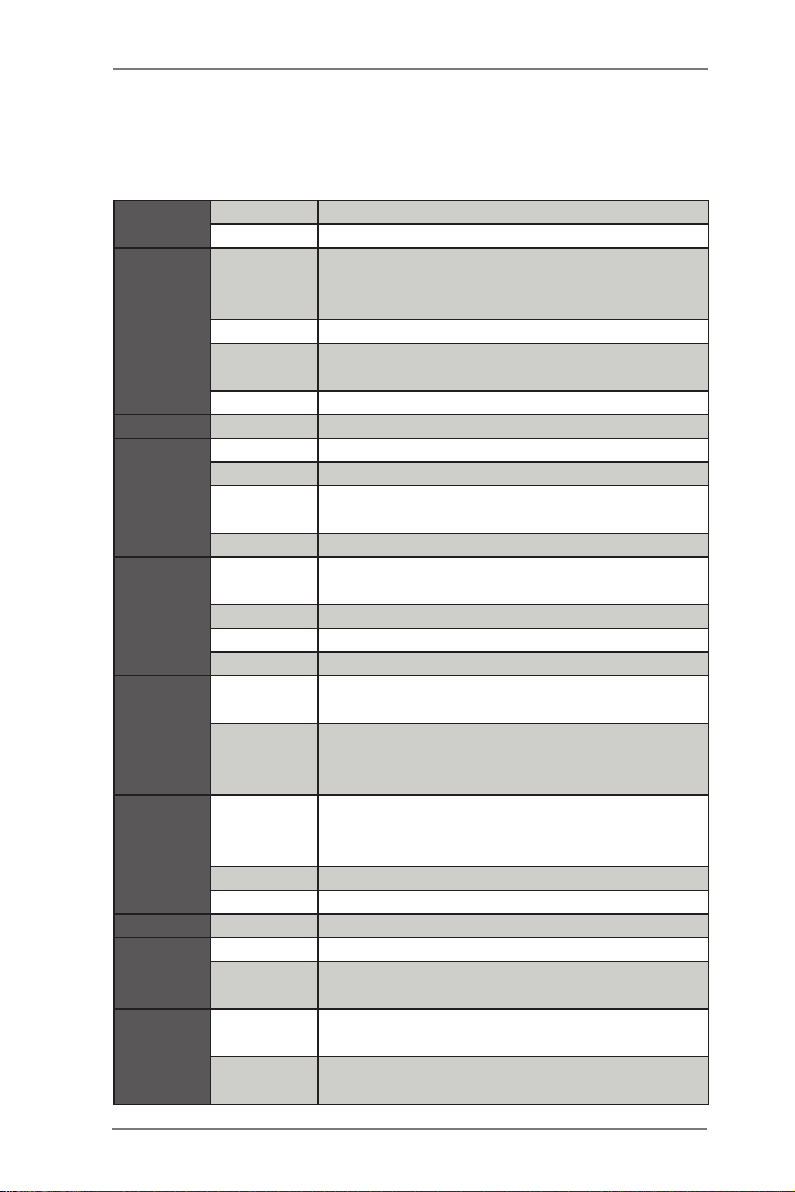
1.2 Specications
Physical
Status
Processor
System
BIOS BIOS Type 64Mb AMI UEFI Legal BIOS
System
Memory
Expansion
Slot
Storage
Graphics
Audio Audio Codec Realtek ALC1150
Ethernet
Rear
Panel I/O
Form Factor ATX
Dimension 12'' x 9.6'' (30.5 cm x 24.4 cm)
Intel® Xeon® processor E3-1200 v3 product
CPU
Socket Single socket (LGA1150)
Power
Phase
Chipset Intel® C226
Capacity 32GB DDR3 UDIMM
Socket 4 x 240-pin DDR3 DIMM slots
Type
Voltage 1.35V, 1.5V
PCIe 3.0 x
16
PCIe 2.0 x 4 1 slot (PCIE1: x4 mode)
PCIe 2.0 x 1 3 slots (PCIE4/PCIE5/PCIE7)
PCI 1 slot (PCI2)
SATA
Controller
A d d it i o n a l
SATA
Controller
Controller
VRAM Max. shared memory 1760MB
Output Max. 2048x1536 @ 75Hz
Interface Gigabit LAN 10/100/1000 Mb/s
LAN
Controller
LAN Port
(RJ45)
PS/2 KB/
Mouse
family & Haswell i7, i5 , i3, Pentuim and Celeron
CPU
6 power phase design
Dual Channel DDR3 1600/1333 UDIMM and
ECC UDIMM
2 slots (PCIE6/PCIE3: x16/x0 or x8/x8 mode)
Intel® C226: 6 x SATA3 6.0 Gb/s
2 x Marvell SE9172: 4 x SATA3 6.0 Gb/s
(1 share with eSATA)
Intel® HD Graphics Built-in Visuals and the VGA
outputs can be supported only with processors
which are GPU integrated
2 x Intel® i210
2
1
6
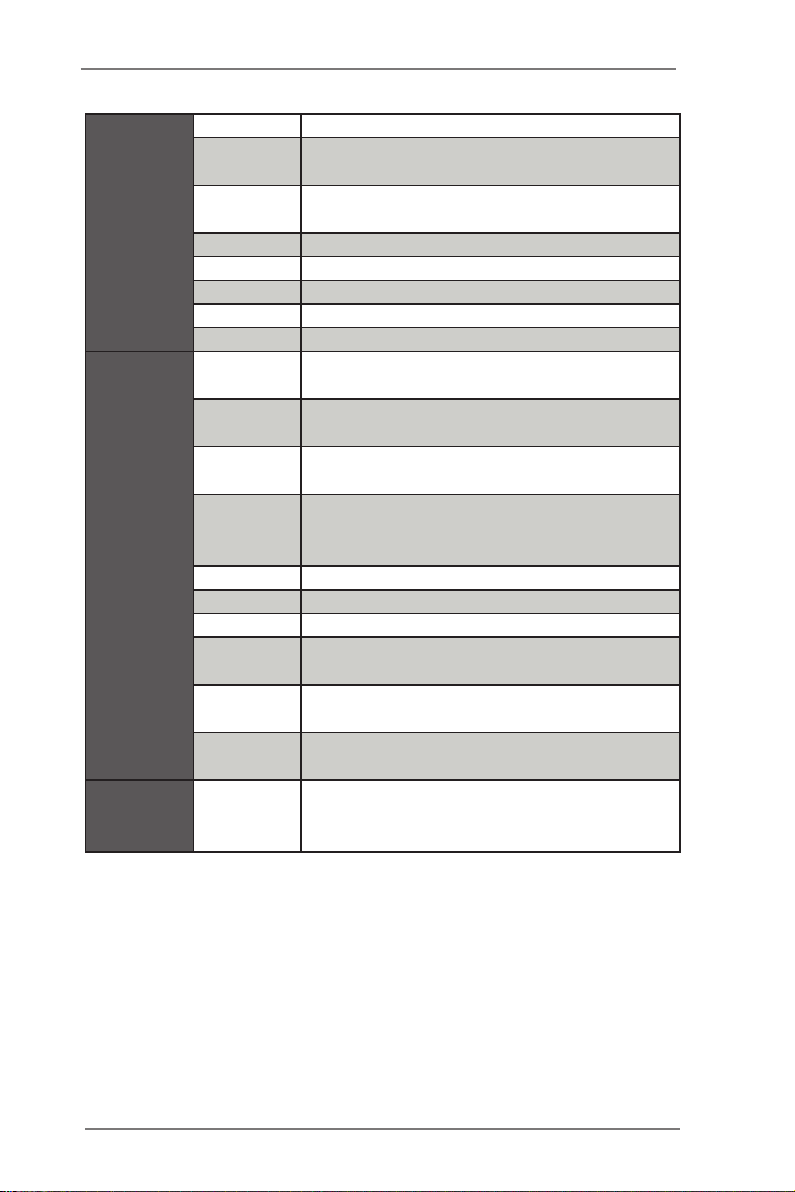
VGA Port 1 x HDMI + 1 x DVI-I + 1 x DisplayPort
USB 2.0
Port
USB 3.0
Port
COM Port
SPDIF 1
eSATA3 1
1394 1
Audio 5 + 1 Jack
COM Port
Header
IR Header N/A
CIR Header N/A
Auxiliary
Panel
Internal
Connectors
Support OS OS
Header
TPM Header 1
Fan Header 6 (2 x 4-pin, 4 x 3-pin)
ATX Power
USB 2.0
Header
USB 3.0
Header
1394
Header
4
4
N/A
1
1 (includes chassis intrusion, front LAN LED)
1 (24-pin) + 1 (8-pin)
3 (each supports 2 USB 2.0)
1 (each supports 2 USB 3.0)
N/A
Microsoft® Windows® 8 / 8 64-bit / 7 / 7 64-bit
/ Microsoft® Windows® Server 2008 R2 (64bit)
and Linux compliant
7

1.3 Unique Features
ASRock Instant Flash
ASRock Instant Flash is a BIOS ash utility embedded in Flash
ROM. This convenient BIOS update tool allows you to update
system BIOS without entering operating systems rst like MS-
DOS or Windows®. With this utility, you can press the <F6> key
during the POST or the <F2> key to enter into the BIOS setup
menu to access ASRock Instant Flash. Just launch this tool and
save the new BIOS le to your USB ash drive, oppy disk or
hard drive, then you can update your BIOS only in a few clicks
without preparing an additional oppy diskette or other compli-
cated ash utility. Please be noted that the USB ash drive or
hard drive must use FAT32/16/12 le system.
8
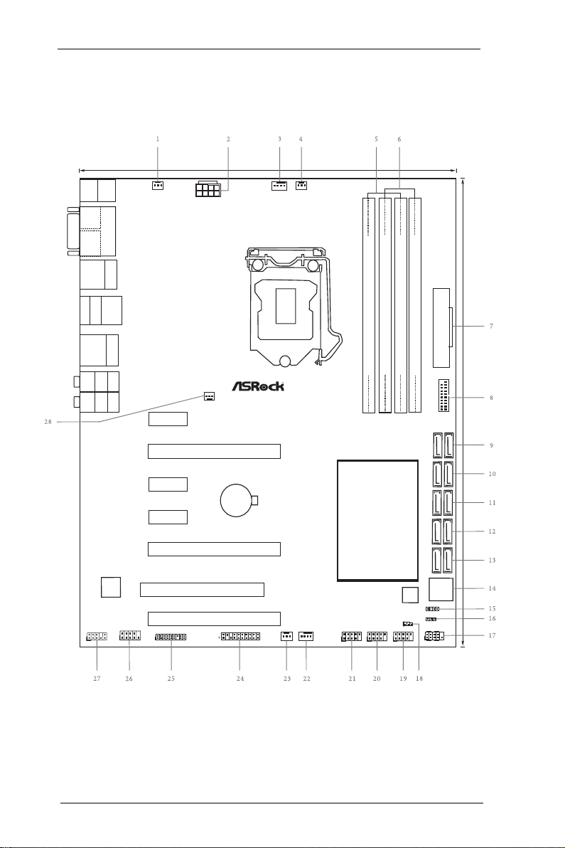
1.4 Motherboard Layout
Intel
C226
CMO S
Bat ter y
DDR 3_A 1 ( 64 bit, 240 -pi n m odu le)
DDR 3_A 2 ( 64 bit, 240 -pi n m odu le)
DDR 3_B 1 ( 64 bit, 240 -pi n m odu le)
DDR 3_B 2 ( 64 bit, 240 -pi n m odu le)
ATXP WR 1
64Mb
BIOS
USB3_4 _5
24. 4cm (9 .6 in)
30. 5cm (1 2. 0 i n)
C2 26 W S
PWR_FAN1
ATX12V1
CHA_FAN3
CPU_FAN2
CPU_FAN1
Supe r
I/O
PCI E7
PCI E6
PCI 2
RoH S
1
HD_AUDI O1
CHA_FAN1
USB8_91USB6_7
1
CLRCMOS1
1
HDLED RES ET
PLED PWRBTN
PANEL1
1
SPEAKER1
1
PLED1
1
CHA_FAN2
SATA3_4_ 5 SATA3_2_ 3 SATA3_0 _1 SATA3 _M2_M 3 SATA3_ M0_M1
Top:
RJ-45
USB 3. 0
T: USB2
B: USB 3
USB 2. 0
T:U SB2
B: USB 3
eSATA_1
IEEE 13 94
Top:
RJ-45
USB 3 .0
T: USB0
B: US B1
Top:
Centra l/Bas s
Center :
REAR SPK
Top:
LINE IN
Center :
FRONT
Bottom :
Optica l
SPDIF
Bottom :
MIC IN
Dr.
Debu g
PCI E5
PCI E4
PCI E3
PCI E1
USB 2. 0
T:U SB0
B: USB 1
PS2
Keybo ard
DVI 1
DIS PLAY1
HDM I1
TPMS1
1
AUX_PAN EL1
USB4_5
1
COM1
1
9

No. Description
1 Power Fan Connector (PWR_FAN1)
2 ATX 12V Power Connector (ATX12V1)
3 CPU Fan Connector (CPU_FAN1)
4 CPU Fan Connector (CPU_FAN2)
5 2 x 240-pin DDR3 DIMM Slots (DDR3_A1, DDR3_B1)
6 2 x 240-pin DDR3 DIMM Slots (DDR3_A2, DDR3_B2)
7 ATX Power Connector (ATXPWR1)
8 USB 3.0 Header (USB3_4_5)
9 SATA3 Connectors (SATA3_M0_M1)
10 SATA3 Connectors (SATA3_M2_M3)
11 SATA3 Connectors (SATA3_0_1)
12 SATA3 Connectors (SATA3_2_3)
13 SATA3 Connectors (SATA3_4_5)
14 Dr. Debug
15 Chassis Speaker Header (SPEAKER1)
16 Power LED Header (PLED1)
17 System Panel Header (PANEL1)
18 Clear CMOS Jumper (CLRCMOS1)
19 USB 2.0 Header (USB4_ 5)
20 USB 2.0 Header (USB6_7)
21 USB 2.0 Header (USB8_9)
22 Chassis Fan Connector (CHA _FAN1)
23 Chassis Fan Connector (CHA _FAN2)
24 Auxiliary Panel Header (AUX_PANEL1)
25 TPM Header (TPMS1)
26 COM Port Header (COM1)
27 Front Panel Audio Header (HD_AUDIO1)
28 Chassis Fan Connector (CHA _FAN3)
10
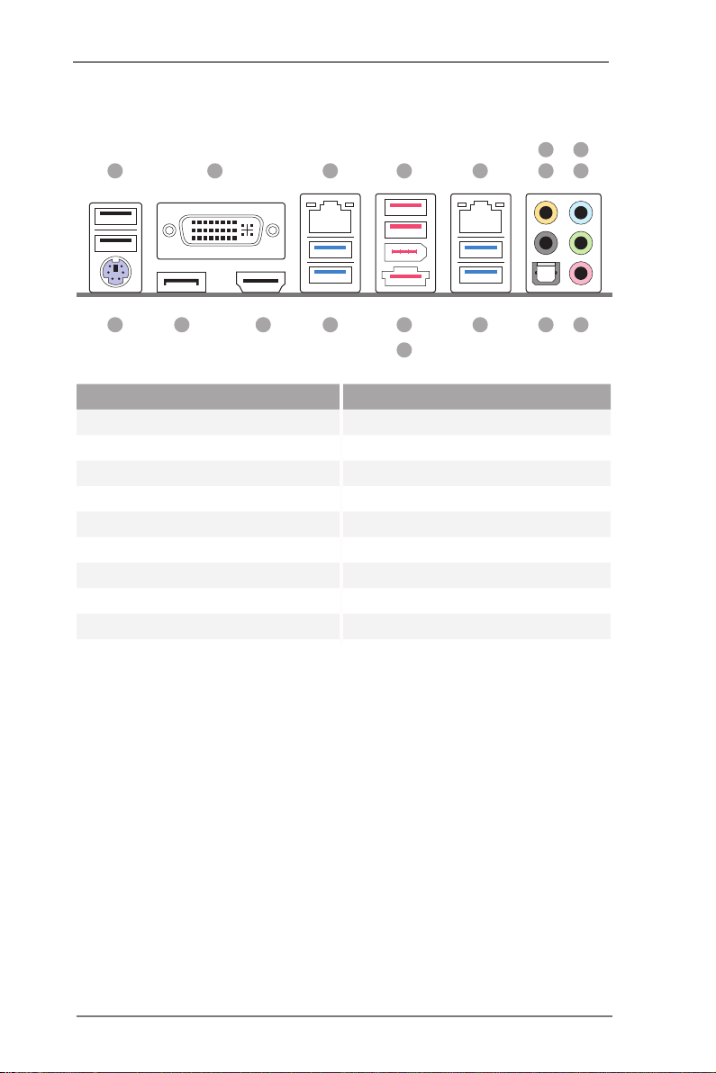
1.5 I/O Panel
1 2 3 754
698
15161718
14
No. Description No. Description
1 USB 2.0 Ports (USB01) 10 Microphone (Pink)
2 DVI-I Port 11 Optical SPDIF Out Port
3 LAN RJ-45 Port 12 USB 3.0 Ports (USB3_01)
4 USB 2.0 Ports (USB23) 13 IEEE 1394 Port
5 LAN RJ-45 Port 14 eSATA Connector
6 Central / Bass (Orange) 15 USB 3.0 Ports (USB3_23)
7 Rear Speaker (Black) 16 HDMI Port
8 Line In (Light Blue) 17 DisplayPort
9 Front Spea ker (Lime) 18 PS/2 Keyboard/Mouse Port
10111213
11
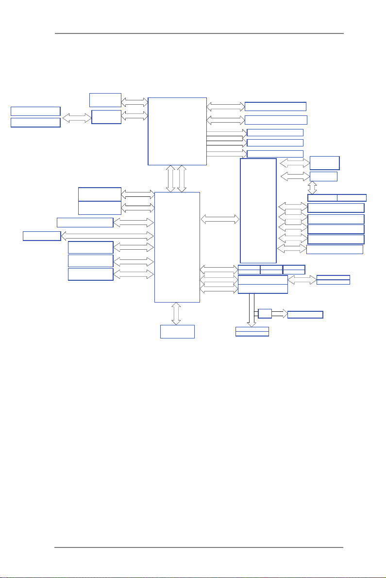
1.6 Block Diagram
QDJ.F!Y27!TMPU
QDJ.F!Y9!TMPU
5!Gspou!VTC4!qpsut
Ijhi.Tqffe!VTC
21!qpsut
QDJ.F!Y5!TMPU
Joufm!MBO!J321!
SPI FLASH
VGA
WSE!23/6
po!Cpbse
QDJf!Hfo4!txjudi
BMD2261
239.cju!Evbm.Diboofm!Nfnpsz!y!5!Tmput
PCI_E BUS
100MHz
591Nc0t
PCIE x4
100MHz
Joufm!Qspdfttps
Haswell Bridge
MHB.2261!Qjo!Tpdlfu
GEJ!MJOL
ENJ
Intel
C226
Diboofm!B
Diboofm!C
DIGITAL PORT B
DIGITAL PORT C
DIGITAL PORT C
QDJF!y2
Lynx Point
PCIE x1
100MHz
64Mb
SPI
PCH
MQD!CVT
TJP
Ovwpupo!ODU7887E
TBUB!CVT
100MHz
QDJF!y2
100MHz
QDJF!y2
100MHz
33MHz
L0C
DPN
EES4!2177024440271103244
EES4!2177024440271103244
EjtqmbzQpsu!Dpoofdups
IENJ!Dpoofdups
EWJ!Dpoofdups
QFY9719
TBUB4`3TBUB4`5
TBUB4`6
Nbswfmm!:283
Nbswfmm!:283
TBUB!CVT
rvjdl!
txjudi
TBUB4`N3
TBUB4`N4!)tibsfe*
PCIE x1
100MHz
PCIE x1
100MHz
PCIE x1
100MHz
PCIE x1
100MHz
PCIE x1
100MHz
PCIE x1
100MHz
PCIE x1
100MHz
TBUB4`1
TBUB4`2TBUB4`4
TBUB!CVT
100MHz
fTBUB4`2!)tibsfe*
C226 WSC226 WSC226 WS
JOUFM!MBO!J321
BTN2194
33MHz
QDJ
QDJ!2 QDJ!3
QDJ.F!Y2!TMPU
QDJ.F!Y2!TMPU
QDJ.F!Y2!TMPU
BTN2153
WJB!WU7426
TBUB4`N1
TBUB4`N2
12
Chapter 2: Installation
This is an ATX form factor (12.0" x 9.6", 30.5 x 24.4 cm) motherboard. Before you
install the motherboard, study the conguration of your chassis to ensure that the
motherboard ts into it.
motherboard. Failure to do so may cause physical injuries to you and
damages to motherboard components.
Make sure to unplug the power cord before installing or removing the
2.1 Screw Holes
Place screws into the holes indicated by circles to secure the motherboard to the
chassis.
Do not over-tighten the screws! Doing so may damage the motherboard.
2.2 Pre-installation Precautions
Take note of the following precautions before you install motherboard components
or change any motherboard settings.
1. Unplug the power cord from the wall socket before touching any
components.
2. To avoid damaging the motherboard’s components due to static
electricity, NEVER place your motherboard directly on the carpet
or the like. Also remember to use a grounded wrist strap or touch a
safety grounded object before you handle the components.
3. Hold components by the edges and do not touch the ICs.
4. Whenever you uninstall any component, place it on a grounded anti-
static pad or in the bag that comes with the component.
5. When placing screws into the screw holes to secure the mother-
board to the chassis, please do not over-tighten the screws! Doing
so may damage the motherboard.
Before you install or remove any component, ensure that the power is
switched off or the power cord is detached from the power supply. Failure to do
so may cause severe damage to the motherboard, peripherals, and/or
components.
13
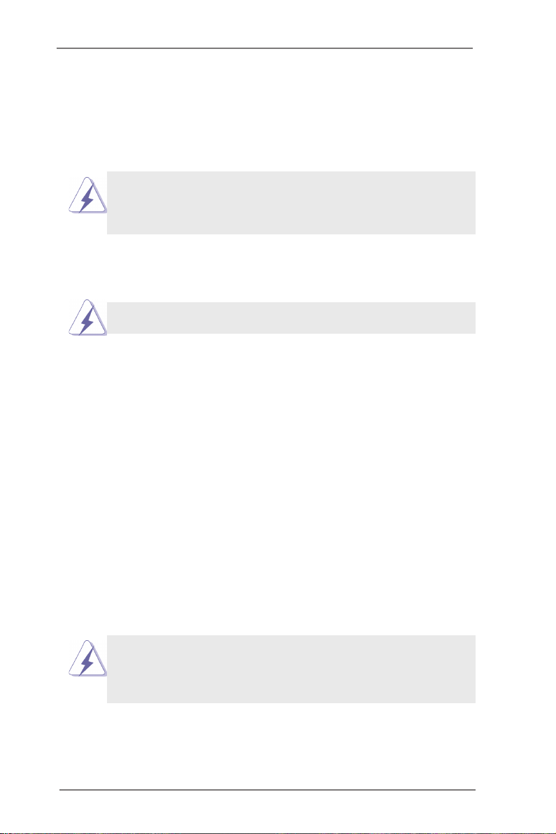
2.3 Installing the CPU
1. Before you insert the 1150-Pin CPU into the socket, please check if the
PnP cap is on the socket, if the CPU surface is unclean, or if there are any
bent pins in the socket. Do not force to insert the CPU into the socket if
above situation is found. Otherwise, the CPU will be seriously damaged.
2. Unplug all power cables before installing the CPU.
1
A
B
2
14
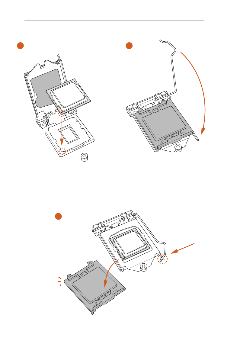
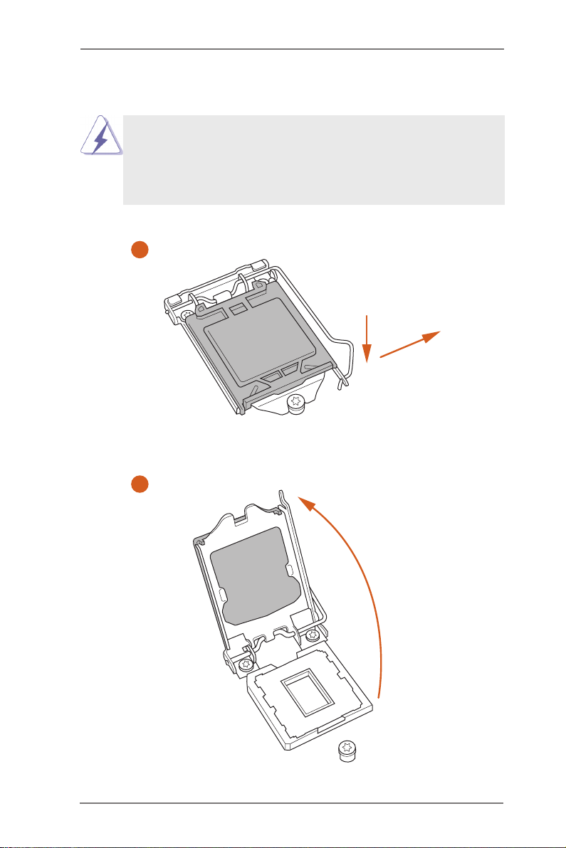
3
5
4
15

must be placed if you wish to return the motherboard for after service.
Please save and replac e the cover if the processor is removed. The cover
16
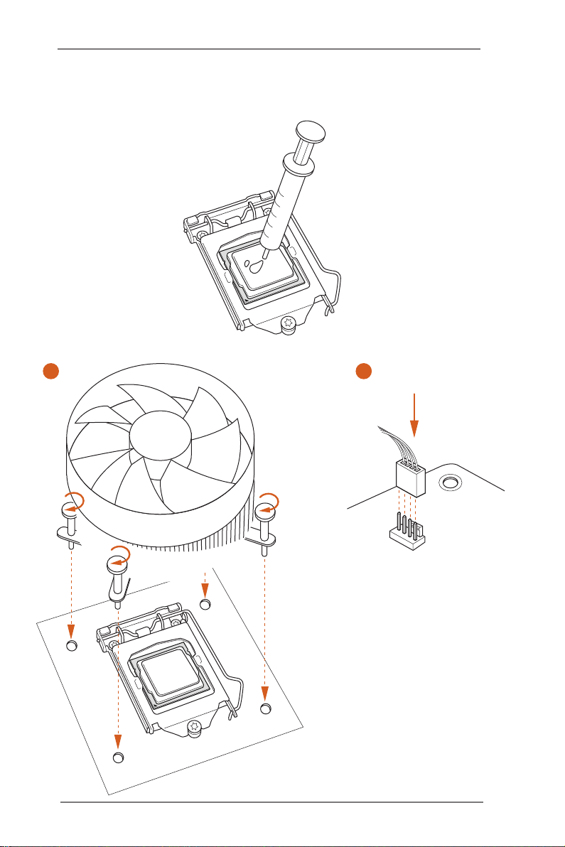
2.4 Installing the CPU Fan and Heatsink
1 2
17
FAN
CPU_
2.5 Installation of Memory Modules (DIMM)
This motherboard provides four 240-pin DDR3 (Double Data Rate 3) DIMM
slots, and supports Dual Channel Memory Technology.
1. For dual channel conguration, you always need to install identical
(the same brand, speed, size and chip-t ype) DDR3 DIMM pair s.
2. It is unable to activate Dual Channel Memo ry Technology with
only one or three memory module installed.
3. It is not allowed to install a DDR or DDR2 memory module into a
DDR3 slot; otherwise, this motherboard and DIMM may be dam-
aged.
Dual Channel Memory Conguration
Priority DDR3_ A1 DDR3_ A2 DDR3_B1 DDR3_B2
1 Populated Populated
2 Populated Populated
3 Populated Populated Populated Populated
The DIMM only ts in one correct orientation. It will cause permanent
damage to the motherboard and the DIM M if you force the DIMM into
the slot at incorrect orientation.
18
 Loading...