

Page 1
Copyright Notice:Copyright Notice:
Copyright Notice:
Copyright Notice:Copyright Notice:
No part of this installation guide may be reproduced, transcribed, transmitted, or translated in any language, in any form or by any means, except duplication of documentation by the purchaser for backup purpose, without written consent of ASRock Inc.
Products and corporate names appearing in this guide may or may not be registered
trademarks or copyrights of their respective companies, and are used only for identification or explanation and to the owners’ benefit, without intent to infringe.
Disclaimer:Disclaimer:
Disclaimer:
Disclaimer:Disclaimer:
Specifications and information contained in this guide are furnished for informational
use only and subject to change without notice, and should not be constructed as a
commitment by ASRock. ASRock assumes no responsibility for any errors or omissions
that may appear in this guide.
With respect to the contents of this guide, ASRock does not provide warranty of any kind,
either expressed or implied, including but not limited to the implied warranties or
conditions of merchantability or fitness for a particular purpose. In no event shall
ASRock, its directors, officers, employees, or agents be liable for any indirect, special,
incidental, or consequential damages (including damages for loss of profits, loss of
business, loss of data, interruption of business and the like), even if ASRock has been
advised of the possibility of such damages arising from any defect or error in the guide
or product.
This device complies with Part 15 of the FCC Rules. Operation is subject to the
following two conditions:
(1) this device may not cause harmful interference, and
(2) this device must accept any interference received, including interference that
may cause undesired operation.
CALIFORNIA, USA ONLY
The Lithium battery adopted on this motherboard contains Perchlorate, a toxic
substance controlled in Perchlorate Best Management Practices (BMP) regulations
passed by the California Legislature. When you discard the Lithium battery in
California, USA, please follow the related regulations in advance.
“Perchlorate Material-special handling may apply, see
www.dtsc.ca.gov/hazardouswaste/perchlorate”
ASRock Website: http://www.asrock.com
Published August 2007
Copyright©2007 ASRock INC. All rights reserved.
ASRock ALiveNF5SLI-1394 Motherboard
EnglishEnglish
EnglishEnglish
English
11
1
11
Page 2
Motherboard LMotherboard L
Motherboard L
Motherboard LMotherboard L
ayoutayout
ayout
ayoutayout
English
EnglishEnglish
EnglishEnglish
22
2
22
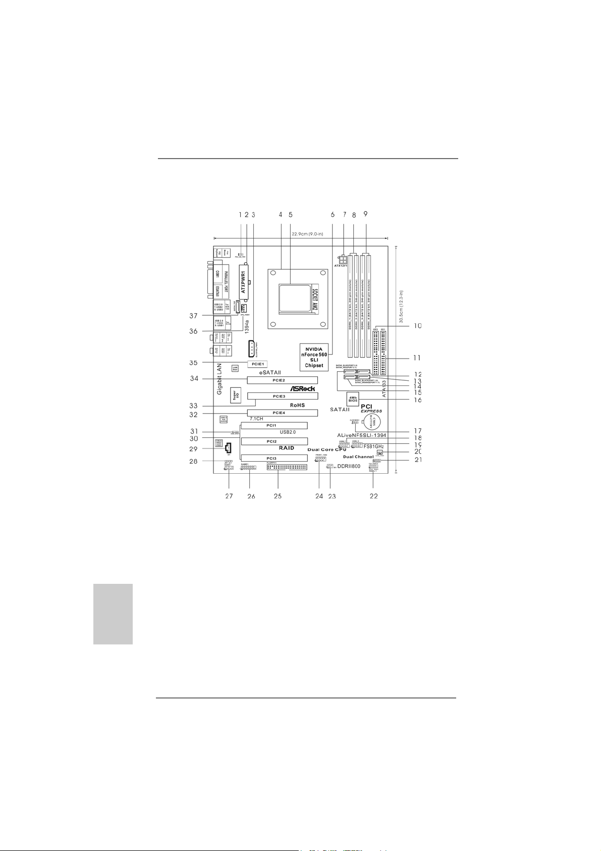
1 PS2_USB_PW1 Jumper 19 USB 2.0 Header (USB4_5, Blue)
2 ATX Power Connector (ATXPWR1) 20 Chassis Fan Connector (CHA_FAN1)
3 SLI / XFIRE Power Connector 21 Chassis Speaker Header (SPEAKER 1)
4 CPU Heatsink Retention Module 22 System Panel Header (PANEL1)
5 AM2 940-Pin CPU Socket 23 Infrared Module Header (IR1)
6 NVIDIA nForce 560 SLI Chipset 24 Front Panel IEEE 1394 Header
7 ATX 12V Power Connector (ATX12V1) (FRONT_1394)
8 2 x 240-pin DDRII DIMM Slots 25 Floppy Connector (FLOPPY1)
(Dual Channel A: DDRII_1, DDRII_2; Yellow) 26 Game Port Header (GAME1)
9 2 x 240-pin DDRII DIMM Slots 27 Front Panel Audio Header (AUDIO1)
(Dual Channel B: DDRII_3, DDRII_4; Orange) 28 JR1 JL1 Jumper
10 Secondary IDE Connector (IDE2, Black) 29 Internal Audio Connector: CD1 (Black)
11 Primary IDE Connector (IDE1, Blue) 30 PCI Slots (PCI1- 3)
12 SATAII Connector (SATAII_BLACK (PORT 1.0)) 31 HDMI_SPDIF Header (HDMI_SPDIF1)
13 SATAII Connector (SATAII_ORANGE (PORT 1.1))32 PCI Express x8 Slot (PCIE4, Yellow)
14 SATAII Connector (SATAII_RED (PORT 2.1)) 33 PCI Express x16 Slot (PCIE3, White)
15 SATAII Connector (SATAII_BLUE (PORT 2.0)) 34 PCI Express x8 Slot (PCIE2, Yellow)
16 Flash Memory 35 PCI Express x1 Slot (PCIE1)
17 Clear CMOS Jumper (CLRCMOS1) 36 CPU Fan Connector (CPU_FAN1)
18 USB 2.0 Header (USB6_7, Blue) 37 eSATAII Connector (eSATAII_TOP)
ASRock ALiveNF5SLI-1394 Motherboard
Page 3
ASRASR
ock 1394_eSock 1394_eS
ASR
ock 1394_eS
ASRASR
ock 1394_eSock 1394_eS
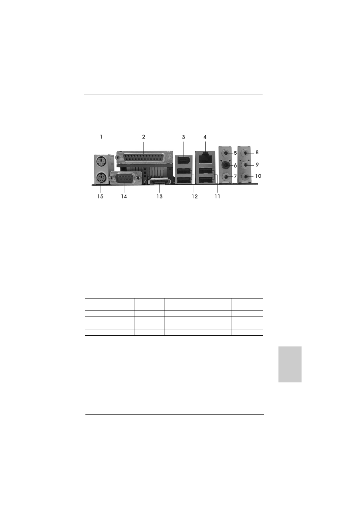
1 PS/2 Mouse Port (Green) * 9 Front Speaker (Lime)
2 Parallel Port 10 Microphone (Pink)
3 IEEE 1394 Port 11 USB 2.0 Ports (USB23)
4 RJ-45 Port 12 USB 2.0 Ports (USB01)
5 Side Speaker (Gray) 13 eSAT AII Port
6 Rear Speaker (Black) 14 COM Port
7 Central / Bass (Orange) 15 PS/2 Keyboard Port (Purple)
8 Line In (Light Blue)
* If you use 2-channel spea ker, please connect the spe aker’s plug into “Front Speaker Jack”. See
the table below for connection details in accordance with the type of speaker you use.
AA
TT
AII I/O PlusAII I/O Plus
A
T
AII I/O Plus
AA
TT
AII I/O PlusAII I/O Plus
TABLE for Audio Output Connection
Audio Output Channels Front Speaker Rear Speaker Central / Bass Side Speaker
(No. 9) (No. 6) (No. 7) (No. 5)
2 V -- -- -4 V -- -- V
6V--VV
8 VVVV
* If you install Windows
audio source (2-channel, 4-channel, 6-channel or 8-channel), then the copy source function of
C-Media audio application can work properly.
* If you install Windows
from your system, please disable the option “USB 2.0 Support” in BIOS setup first.
®
VistaTM or VistaTM 64-bit OS, please correctly select the channel of the
®
VistaTM or VistaTM 64-bit OS and want to remove C-Media audio driver
ASRock ALiveNF5SLI-1394 Motherboard
EnglishEnglish
EnglishEnglish
English
33
3
33
Page 4
1.1.
IntroductionIntroduction
1.
Introduction
1.1.
IntroductionIntroduction
Thank you for purchasing ASRock ALiveNF5SLI-1394 motherboard, a reliable
motherboard produced under ASRock’s consistently stringent quality control. It delivers excellent performance with robust design conforming to ASRock’s commitment to quality and endurance.
This Quick Installation Guide contains introduction of the motherboard and step-bystep installation guide. More detailed information of the motherboard can be found in
the user manual presented in the Support CD.
Because the motherboard specifications and the BIOS software might
be updated, the content of this manual will be subject to change without
notice. In case any modifications of this manual occur, the updated
version will be available on ASRock website without further notice. You
may find the latest VGA cards and CPU support lists on ASRock
website as well.
ASRock website http://www.asrock.com
1.11.1
Package ContentsPackage Contents
1.1
Package Contents
1.11.1
Package ContentsPackage Contents
1 x ASRock ALiveNF5SLI-1394 Motherboard
(ATX Form Factor: 12.0-in x 9.0-in, 30.5 cm x 22.9 cm)
1 x ASRock SLI Bridge
1 x ASRock ALiveNF5SLI-1394 Quick Installation Guide
1 x ASRock ALiveNF5SLI-1394 Support CD
1 x Ultra ATA 66/100/133 IDE Ribbon Cable (80-conductor)
1 x 3.5-in Floppy Drive Ribbon Cable
2 x Serial ATA (SATA) Data Cables (Optional)
1 x Serial ATA (SATA) HDD Power Cable (Optional)
1 x HDMI_SPDIF Cable (Optional)
1 x “ASRock 1394_eSATAII I/O Plus” I/O Shield
English
EnglishEnglish
EnglishEnglish
44
4
44
ASRock ALiveNF5SLI-1394 Motherboard
Page 5
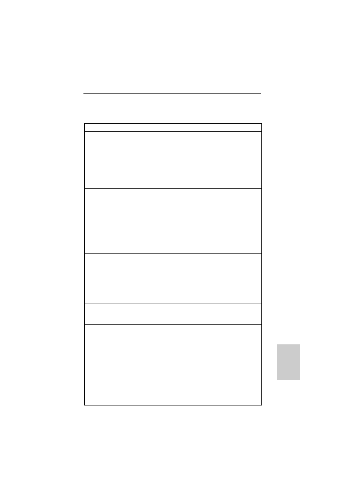
1.21.2
SpecificationsSpecifications
1.2
Specifications
1.21.2
SpecificationsSpecifications
Platform - ATX Form Factor: 12.0-in x 9.0-in, 30.5 cm x 22.9 cm
CPU - Socket AM2 for AMD AthlonTM 64FX / 64X2 / X2 / 64 and
Sempron processors
- AMD LIVE!TM Ready
- Supports AMD’s Cool ‘n’ QuietTM Technology
- FSB 1000 MHz (2.0 GT/s)
- Supports Untied Overclocking Technology (see CAUTION 1)
- Supports Hyper-Transport Technology
Chipset - NVIDIA® nForce 560 SLI
Memory - Dual Channel DDRII Memory Te chnology (see CAUTION 2)
- 4 x DDRII DIMM slots
- Support DDRII800/667/533
- Max. capacity: 8GB (see CAUTION 3)
Hybrid Booster - CPU Frequency Stepless Control (see CAUTION 4)
- ASRock U-COP (see CAUTION 5)
- Boot Failure Guard (B.F.G.)
- ASRock AM2 Boost: ASRock Patented T echnology to boost
memory performance up to 12.5% (see CAUTION 6)
Expansion Slot - 1 x PCI Express x16 slot (White)
- 2 x PCI Express x8 slots (Yellow; for NVIDIA® SLITM only)
- 1 x PCI Express x1 slot
- 3 x PCI slots
- Supports NVIDIA® SLITM (see CAUTION 7)
Audio - 7.1 CH Windows® VistaTM Premium Level Superior Audio
(C-Media CM6501 Audio Codec with UAA architecture)
LAN - Gigabit LAN 10/100/1000 Mb/s
- Giga PHY Realtek RTL8211B
- Supports Wake-On-LAN
Rear Panel I/O ASRock 1394_eSATAII I/O Plus
- 1 x PS/2 Mouse Port
- 1 x PS/2 Keyboard Port
- 1 x Serial Port: COM1
- 1 x Parallel Port (ECP/EPP Support)
- 4 x Ready-to-Use USB 2.0 Ports
- 1 x eSATAII Port
- 1 x RJ-45 Port
- 1 x IEEE 1394 Port
- HD Audio Jack: Side Speaker/Rear Speaker/Central/Bass/
Line in/Front Speaker/Microphone (see CAUTION 8)
EnglishEnglish
EnglishEnglish
English
ASRock ALiveNF5SLI-1394 Motherboard
55
5
55
Page 6
English
EnglishEnglish
EnglishEnglish
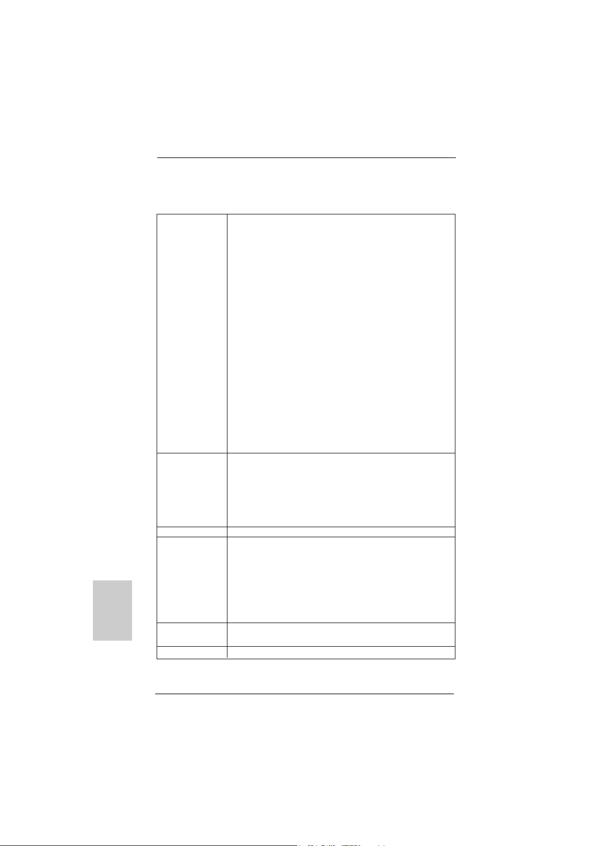
Connector - 4 x SATAII 3.0Gb/s connectors, support RAID (RAID 0,
RAID 1, RAID 0+1, JBOD and RAID 5), NCQ a nd “Hot Plug”
functions (see CAUTION 9)
- 1 x eSATAII 3.0Gb/s connector (shared with 1 SATAII
connector), supports NCQ and “Hot Plug” functions
(see CAUTION 10)
- 2 x ATA133 IDE connectors (support 4 x IDE devices)
- 1 x Floppy connector
- 1 x IR header
- 1 x Game header
- 1 x HDMI_SPDIF header
- 1 x IEEE 1394 header
- CPU/Chassis FAN connector
- 20 pin ATX power connector
- 4 pin 12V power connector
- SLI/XFIRE power connector
- CD in header
- Front panel audio connector
- 2 x USB 2.0 headers (support 4 USB 2.0 ports)
(see CAUTION 11)
BIOS Feature - 4Mb AMI BIOS
- AMI Legal BIOS
- Supports “Plug and Play”
- ACPI 1.1 Compli ance Wa ke Up Events
- Supports jumperfree
- SMBIOS 2.3.1 Support
Support CD - Drivers, Utilities, AntiVirus Software (Trial Version)
Hardware - CPU Internal Temperature Sen sing
Monitor - CPU Ambient Temperature Sensing
- Chassis Temperature Sensing
- CPU Fan Ta chometer
- Chassis Fan Tachometer
- CPU Quiet Fan
- Voltage Monitoring: +12V, +5V, +3.3V, Vcore
OS - Microsoft® Windows® 2000 / XP / XP Media Center / XP 64-bit
/ VistaTM / VistaTM 64-bit compliant (see CAUTION 12)
Certifications - FCC, CE, WHQL Certificated
66
6
66
ASRock ALiveNF5SLI-1394 Motherboard
Page 7

WARNING
Please realize that there is a certain risk involved with overclocking, including adjusting
the setting in the BIOS, applying Untied Overclocking Technology, or using the thirdparty overclocking tools. Overclocking may affect your system stability, or even
cause damage to the components and devices of your system. It should be done at
your own risk and expense. We are not responsible for possible damage caused by
overclocking.
CAUTION!
1. This motherboard supports Untied Overclocking Technology. Please read
“Untied Overclocking Technology” on page 34 for details.
2. This motherboard supports Dual Channel Memory Technology . Before you
implement Dual Channel Memory Technology, make sure to read the
installation guide of memory modules on page 12 for proper installation.
3. Due to the operating system limitation, the actual memory size may be
less than 4GB for the reservation for system usage under Windows® XP
and Windows® VistaTM. For Windows® XP 64-bit and Windows® VistaTM 64bit with 64-bit CPU, there is no such limitation.
4. Although this motherboard offers stepless control, it is not recommended to
perform over-clocking. Frequencies other than the recommended CPU bus
frequencies may cause the instability of the system or damage the CPU.
5. While CPU overheat is detected, the system will automatically shutdown.
Before you resume the system, plea se check if the CPU fa n on the motherboard
functions properly and unplug the power cord, then plug it back again. To
improve heat dissipation, remember to spray thermal grease between the
CPU and the heatsink when you install the PC system.
6. This motherboard supports ASRock AM2 Boost overclocking technology. If
you enable this function in the BIOS setup, the memory performance will
improve up to 12.5%, but the effect still depends on the AM2 CPU you adopt.
Enabling this function will overclock the chipset/CPU reference clock. However,
we can not guarantee the system stability for all CPU/DRAM configurations.
If your system is unstable after AM2 Boost function is enabled, it may not be
applicative to your system. You may choose to disable this function for
keeping the stability of your system.
7. This motherboard supports NVIDIA® SLITM technology. PCIE2 a nd PCIE4 slots
(yellow) are intended for SLI
Express VGA card to this motherboard, please install it to PCIE3 slot. For the
information of the compatible SLITM Mode PCI Express VGA cards, please
refer to the “Supported PCI Express VGA Card List for SLITM Mode” on page 9.
For the proper installation of PCI Express VGA card, please refer to the
installation guide on page 14.
8. For microphone input, this motherboard supports both stereo and mono modes.
For audio output, this motherboard supports 2-channel, 4-channel, 6-channel,
and 8-channel mode s. Please check the table on page 3 for proper connection.
TM
function. If you plan to install only one PCI
EnglishEnglish
EnglishEnglish
English
ASRock ALiveNF5SLI-1394 Motherboard
77
7
77
Page 8

9. Before installing SAT AII hard dis k to SATAII connector, please rea d the “SATAII
Hard Disk Setup Guide” on page 29 to adjust your SATAII hard disk drive to
SATAII mode. You can also connect SATA hard disk to SATAII connector
directly.
10. This motherboard supports eSATAII interface, the external SATAII
specification. Please read “eSATAII Interface Introduction” on page 26 for
details about eSATAII and eSATAII installation procedure s.
11. Power Management for USB 2.0 works fine under Microsoft® Windows
VistaTM 64-bit / VistaTM / XP 64-bit / XP SP1 or SP2 / 2000 SP4.
12. Microsoft® Windows® VistaTM / VistaTM 64-bit driver keeps on updating now. As
long as we have the latest driver, we will update it to our website in the future.
Please visit our website for Microsoft® Windows® VistaTM / VistaTM 64-bit driver
and related information.
ASRock website http://www.asrock.com
1.31.3
Minimum Hardware RMinimum Hardware R
1.3
Minimum Hardware R
1.31.3
Minimum Hardware RMinimum Hardware R
TMTM
TM
TMTM
VistaVista
Vista
VistaVista
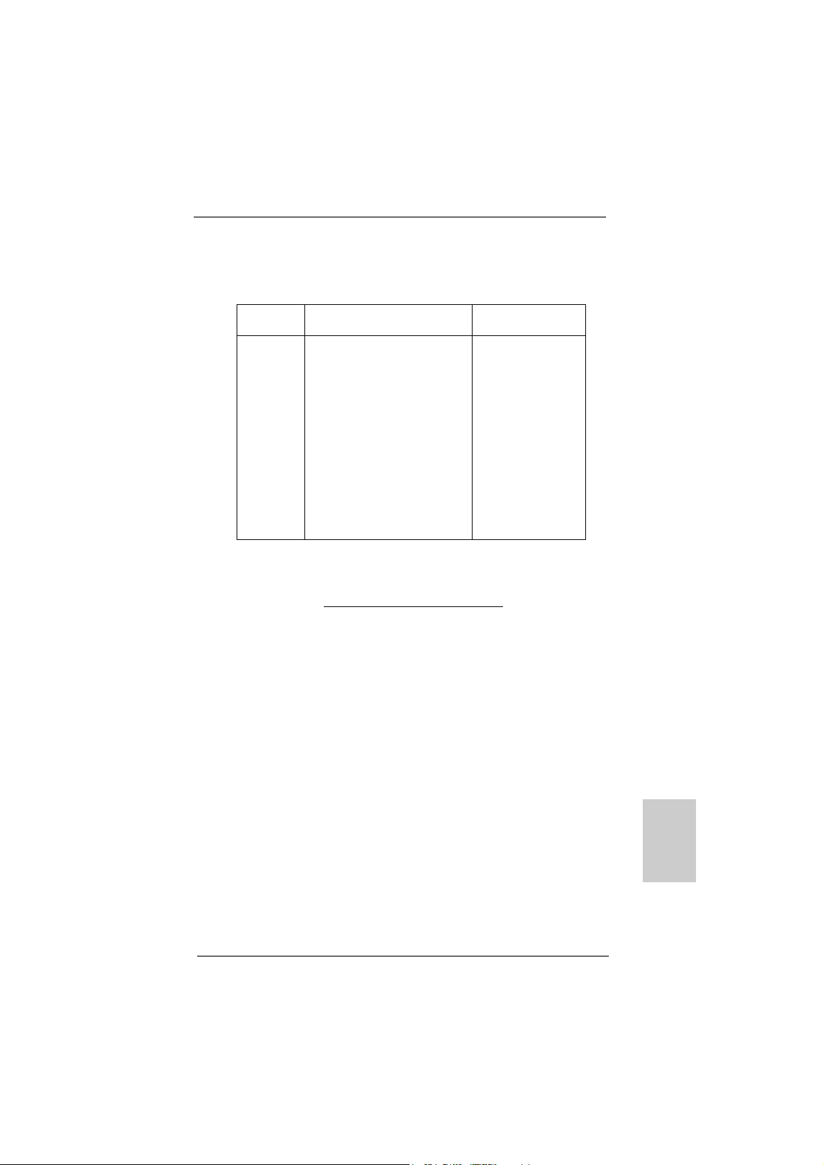
For system integrators and users who purchase this motherboard and
plan to submit Windows® VistaTM Premium 2007 and Basic logo, please
follow below table for minimum hardware requirements.
CPU Sempron 2800+
Memory 1GB system memory (Premium)
VGA DX9.0 with WDDM Driver
Premium 2007 and Basic Logo Premium 2007 and Basic Logo
Premium 2007 and Basic Logo
Premium 2007 and Basic Logo Premium 2007 and Basic Logo
with 128bit VGA memory (Premium)
with 64bit VGA memory (Basic)
equirement Tequirement T
equirement T
equirement Tequirement T
able for Wable for W
able for W
able for Wable for W
®
indowsindows
indows
indowsindows
®®
®
®®
English
EnglishEnglish
EnglishEnglish
88
8
88
* After June 1, 2007, all Windows® VistaTM systems are required to meet above
minimum hardware requirements in order to qualify for Windows® VistaTM Premium
2007 logo.
* To submit Windows® VistaTM logo, it is recommended to use the OS embedded audio
driver for audio function test.
ASRock ALiveNF5SLI-1394 Motherboard
Page 9
1.41.4
Supported PCI Express VGA Card List for SLISupported PCI Express VGA Card List for SLI
1.4
Supported PCI Express VGA Card List for SLI
1.41.4
Supported PCI Express VGA Card List for SLISupported PCI Express VGA Card List for SLI
(for Windows® XP / XP 64-bit / VistaTM / VistaTM 64-bit only)
Graphics Chip Model Name Chipset Name
Vendor
NVIDIA
ASUS EN8800GTX
ASUS EN8600GT/2DHT
ASUS EN7950GX2 *
ASUS EN7900GT TOP
ASUS EN7800GT
ASUS EN7600GSSILENT
ASUS EN7600GT/2DHT
ASUS EN6800LE
ASUS Extreme N6800/TD
ALBATRON PC6600GT
GIGABYTE GV -NX66256DP2
LEADTEK PX7900GS TDH
LEADTEK PX7300GS T DH *
MSI 7300GT-T D256EH
TMTM
TM
TMTM
GeForce 8800GTX
GeForce 8600GT
GeForce 7950GX2
GeForce 7900GT
GeForce 7800GT
GeForce 7600GT
GeForce 7600GS
GeForce 6800LE
GeForce 6800
GeForce 6600GT
GeForce 6600
GeForce 7900GS
GeForce 7300GS
GeForce 7300GT
Mode Mode
Mode
Mode Mode
* These two cards can only work under Windows
For the latest updates of the supported PCI Express VGA card list for SLITM Mode,
please visit our website for details.
ASRock website:
http://www.asrock.com/support/index.htm
®
XP / XP 64-bit OS.
ASRock ALiveNF5SLI-1394 Motherboard
EnglishEnglish
EnglishEnglish
English
99
9
99
Page 10
2.2.
InstallationInstallation
2.
Installation
2.2.
InstallationInstallation
This is an ATX form factor (12.0-in x 9.0-in, 30.5 cm x 22.9 cm) motherboard.
Before you install the motherboard, study the configuration of your chassis to ensure that the motherboard fits into it.
Pre-installation PrecautionsPre-installation Precautions
Pre-installation Precautions
Pre-installation PrecautionsPre-installation Precautions
Take note of the following precautions before you install motherboard
components or change any motherboard settings.
Before you install or remove any component, ensure that the
power is switched off or the power cord is detached from the
power supply. Failure to do so may cause severe damage to the
motherboard, peripherals, and/or components.
1. Unplug the power cord from the wall socket before touching any
component.
2. To avoid damaging the motherboard components due to static
electricity, NEVER place your motherboard directly on the carpet or
the like. Also remember to use a grounded wrist strap or touch a
safety grounded object before you handle components.
3. Hold components by the edges and do not touch the ICs.
4. Whenever you uninstall any component, place it on a grounded antistatic pad or in the bag that comes with the component.
5. When placing screws into the screw holes to secure the motherboard
to the chassis, please do not over-tighten the screws! Doing so may
damage the motherboard.
English
EnglishEnglish
EnglishEnglish
1010
10
1010
ASRock ALiveNF5SLI-1394 Motherboard
Page 11
2.12.1
CPU InstallationCPU Installation
2.1
CPU Installation
2.12.1
CPU InstallationCPU Installation
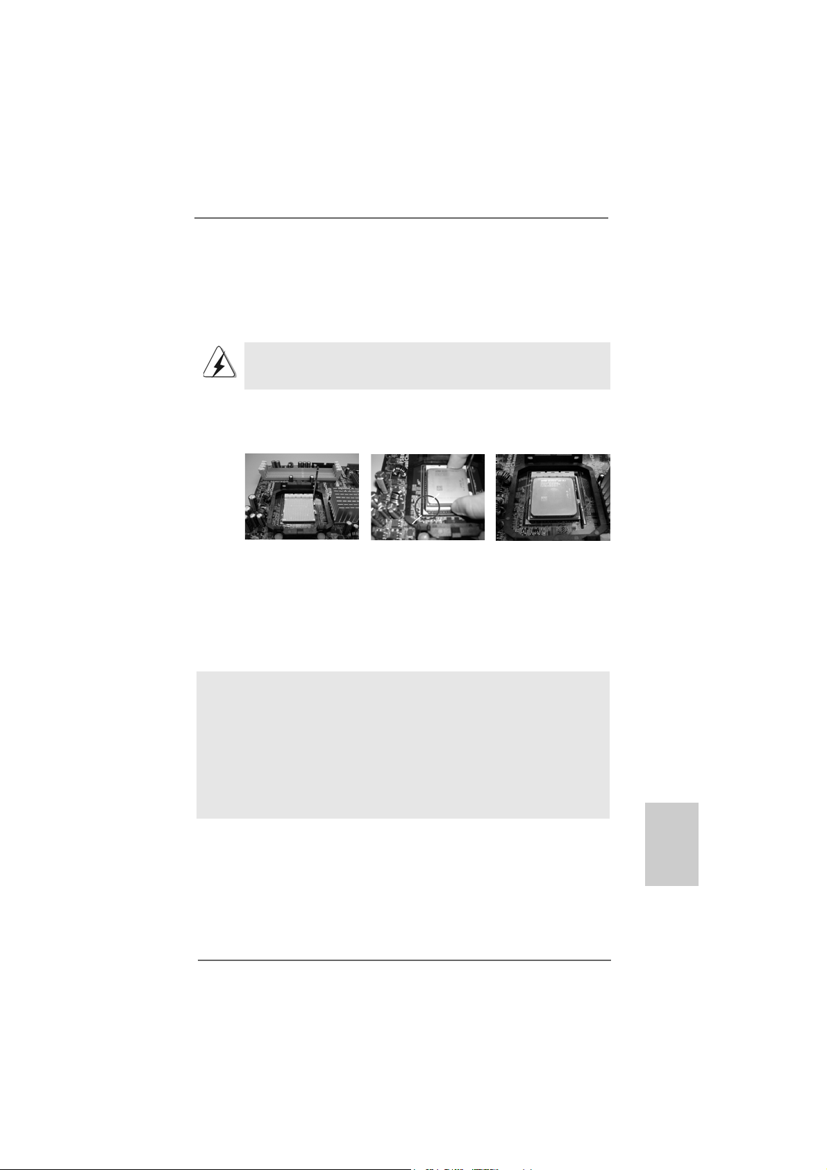
Step 1. Unlock the socket by lifting the lever up to a 90
o
angle.
Step 2. Position the CPU directly above the socket such that the CPU corner with
the golden triangle matches the socket corner with a small triangle.
Step 3. Carefully insert the CPU into the socket until it fits in place.
The CPU fits only in one correct orientation. DO NOT force the CPU
into the socket to avoid bending of the pins.
Step 4. When the CPU is in place, press it firmly on the socket while you push
down the socket lever to secure the CPU. The lever clicks on the side tab
to indicate that it is locked.
Lever 90° Up
STEP 1:
Lift Up The Socket Lever
2.22.2
Installation of CPU Fan and HeatsinkInstallation of CPU Fan and Heatsink
2.2
Installation of CPU Fan and Heatsink
2.22.2
Installation of CPU Fan and HeatsinkInstallation of CPU Fan and Heatsink
CPU Golden Triangle
Socket Corner Small Triangle
STEP 2 / STEP 3:
Match The CPU Golden Triangle
To The Socket Corner Small
Triangle
STEP 4:
Push Down And Lock
The Socket Lever
After you install the CPU into this motherboard, it is necessary to install a
larger heatsink and cooling fan to dissipate heat. You also need to spray
thermal grease between the CPU and the heatsink to improve heat
dissipation. Make sure that the CPU and the heatsink are securely fastened and in good contact with each other. Then connect the CPU fan to
the CPU FAN connector (CPU_FAN1, see Page 2, No. 36). For proper
installation, please kindly refer to the instruction manuals of the CPU fan
and the heatsink.
EnglishEnglish
EnglishEnglish
English
ASRock ALiveNF5SLI-1394 Motherboard
1111
11
1111
Page 12
2.3 Installation of Memory Modules (DIMM)2.3 Installation of Memory Modules (DIMM)
2.3 Installation of Memory Modules (DIMM)
2.3 Installation of Memory Modules (DIMM)2.3 Installation of Memory Modules (DIMM)
This motherboard provides four 240-pin DD RII (Double Data Rate II) DIMM slots,
and supports Dual Channel Memory Technology. For dual channel configuration,
you always need to install identical (the same brand, speed, size and chiptype) DDRII DIMM pair in the slots of the same color. In other words, you have to
install identical DDRII DIMM pair in Dual Channel A (DDRII_1 and DDRII_2;
Yellow slots; see p.2 No.8) or identical DDRII DIMM pair in Dual Channel B
(DDRII_3 and DDRII_4; Ora nge slots; see p.2 No.9), so that Dual Cha nnel Memory
Technology can be activated. This motherboard also allows you to install four
DDRII DIMMs for dual channel configuration, and please install identical DDRII
DIMMs in all four slots. You may refer to the Dual Channel Memory Configuration
Table below.
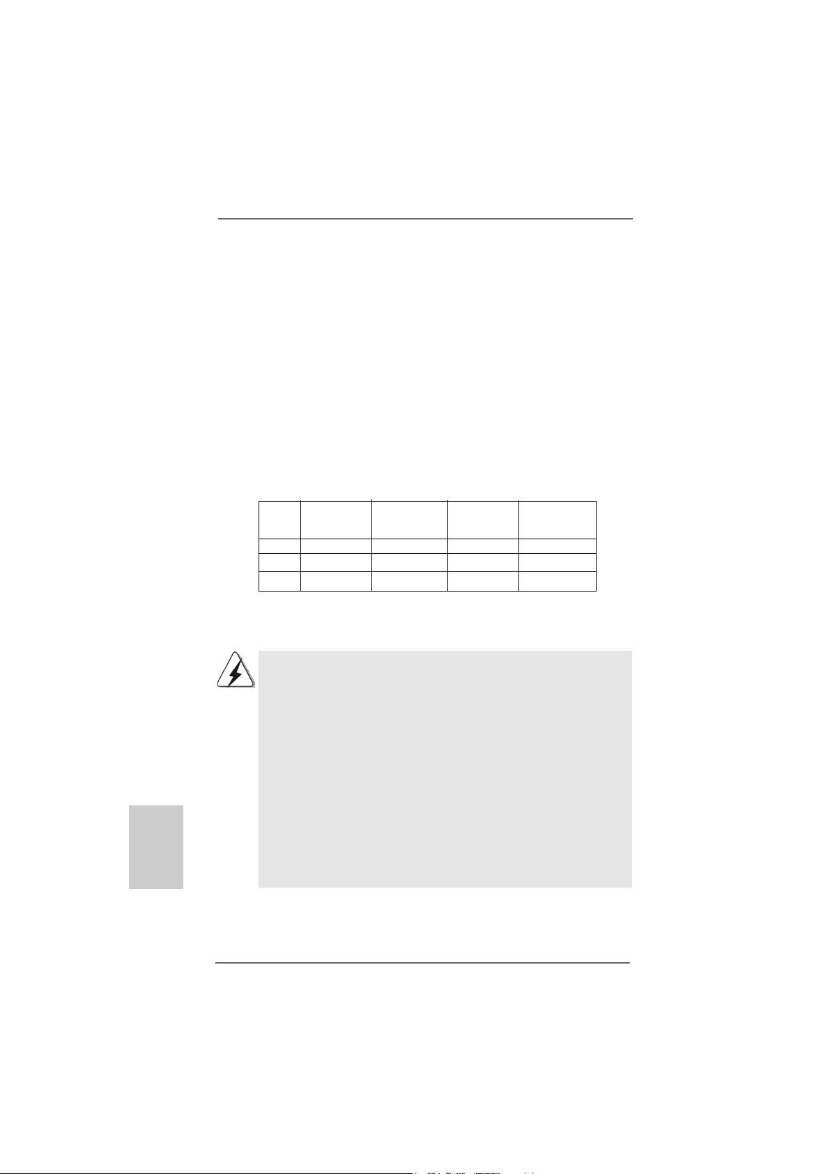
Dual Channel Memory Configurations
DDRII_1 DDRII_2 DDRII_3 DDRII_4
(Yellow Slot) (Yellow Slot) (Orange Slot) (Orange Slot)
(1) Populated Populated - (2) - - Populated Populated
(3)* Populated Populated Populated Populated
* For the configuration (3), please install identical DD RII DIMM s in all four slots.
English
EnglishEnglish
EnglishEnglish
1212
12
1212
1. If you want to install two memory modules, for optimal compatibility
and reliability, it is recommended to install them in the slots of the
same color. In other words, install them either in the set of yellow
slots (DDRII_1 and DDRII_2), or in the set of orange slots (DDRII_3
and DDRII_4).
2. If only one memory module or three memory modules are installed
in the DDRII DIMM slots on this motherboard, it is unable to activate
the Dual Channel Memory Technology .
3. If a pair of memory modules is NOT installed in the same Dual
Channel, for exa mple, in stalling a pair of memory module s in D DRII_1
and DDRII_3, it is unable to activate the Dual Channel Memory
Technology .
4. It is not allowed to install a DDR memory module into DDRII slot;
otherwise, this motherboard and DIMM may be damaged.
ASRock ALiveNF5SLI-1394 Motherboard
Page 13
Installing a DIMMInstalling a DIMM
Installing a DIMM
Installing a DIMMInstalling a DIMM
Please make sure to disconnect power supply before adding or
removing DIMMs or the system components.
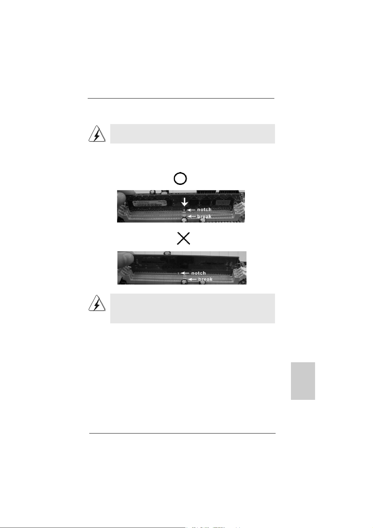
Step 1. Unlock a DIMM slot by pressing the retaining clips outward.
Step 2. Align a DIMM on the slot such that the notch on the DIMM matches the brea k
on the slot.
The DIMM only fits in one correct orientation. It will cause permanent
damage to the motherboard and the DIMM if you force the DIMM into the
slot at incorrect orientation.
Step 3. Firmly insert the DIMM into the slot until the retaining clips at both ends fully
snap back in place and the DIMM is properly seated.
ASRock ALiveNF5SLI-1394 Motherboard
1313
13
1313
EnglishEnglish
EnglishEnglish
English
Page 14
English
EnglishEnglish
EnglishEnglish
2.4 Expansion Slots (PCI and PCI Express Slots)2.4 Expansion Slots (PCI and PCI Express Slots)
2.4 Expansion Slots (PCI and PCI Express Slots)
2.4 Expansion Slots (PCI and PCI Express Slots)2.4 Expansion Slots (PCI and PCI Express Slots)
There are 3 PCI slots and 4 PCI Express slots on this motherboard.
PCI Slots: PCI slots are used to install expansion cards that have the 32-bit PCI
interface.
PCIE Slots:
PCIE1 (PCIE x1 slot) is used for PCI Express cards with x1 lane width
cards, such as Gigabit LAN card, SATA2 card, etc.
PCIE2 / PCIE4 (PCIE x8 slot) is used to install PCI Express expansion
cards to support SLITM function. For the information of the compatible
SLITM Mode PCI Express VGA cards, please refer to the “Supported PCI
Express VGA Card List for SLITM Mode” on page 9.
PCIE3 (PCIE x16 slot) is used for PCI Express cards with x16 lane
width graphics cards.
1. This motherboard supports NVIDIA® SLITM technology. PCIE2 and
PCIE4 slots (yellow) are intended for SLITM function only. It is not
recommended to install other graphics cards on PCIE2 and PCIE4
slots, and we do not guarantee that your graphics cards can work
successfully under this situation.
2. You can only choose to use either PCIE3 slot or PCIE2 / PCIE4 slot on
this motherboard. If you plan to install only one PCI Express VGA card
to this motherboard, please install it to PCIE3 slot.
Installing an expansion cardInstalling an expansion card
Installing an expansion card
Installing an expansion cardInstalling an expansion card
Step 1. Before installing the expansion card, please make sure that the power
supply is switched off or the power cord is unplugged. Please read the
documentation of the expansion card and make necessary hardware
settings for the card before you start the installation.
Step 2. Remove the system unit cover (if your motherboard is already installed in
a chassis).
Step 3. Remove the bracket facing the slot that you intend to use. Keep the
screws for later use.
Step 4. Align the card connector with the slot and press firmly until the card is
completely seated on the slot.
Step 5. Fasten the card to the chassis with screws.
Step 6. Replace the system cover.
1414
14
1414
ASRock ALiveNF5SLI-1394 Motherboard
Page 15
TMTM
TM
2.5 SLI2.5 SLI
2.5 SLI
2.5 SLI2.5 SLI
TMTM
Operation Guide Operation Guide
Operation Guide
Operation Guide Operation Guide
This motherboard supports NVIDIA® SLITM (Scalable Link Interface) technology that
allows you to install two identical NVIDIA® SLI
TM
enabled PCI Express x16 graphics
cards. Currently, NVIDIA® SLITM technology supports Windows® XP, XP 64-bit, Vista
and VistaTM 64-bit OS. Please follow the installation procedures in this section.
TM
SLI
Technology Requirements
1. You should have two identical SLITM-ready graphics cards that are NVIDIA
certified.
2. Make sure that your graphics card driver supports the NVIDIA
SLITM technology. Download the latest driver from the NVIDIA® website
(www.nvidia.com).
3. Make sure that your power supply unit (PSU) can provide at least the
minimum power required by your system.
TMTM
TM
Enjoy the benefit of SLIEnjoy the benefit of SLI
Enjoy the benefit of SLI
Enjoy the benefit of SLIEnjoy the benefit of SLI
TMTM
®
®
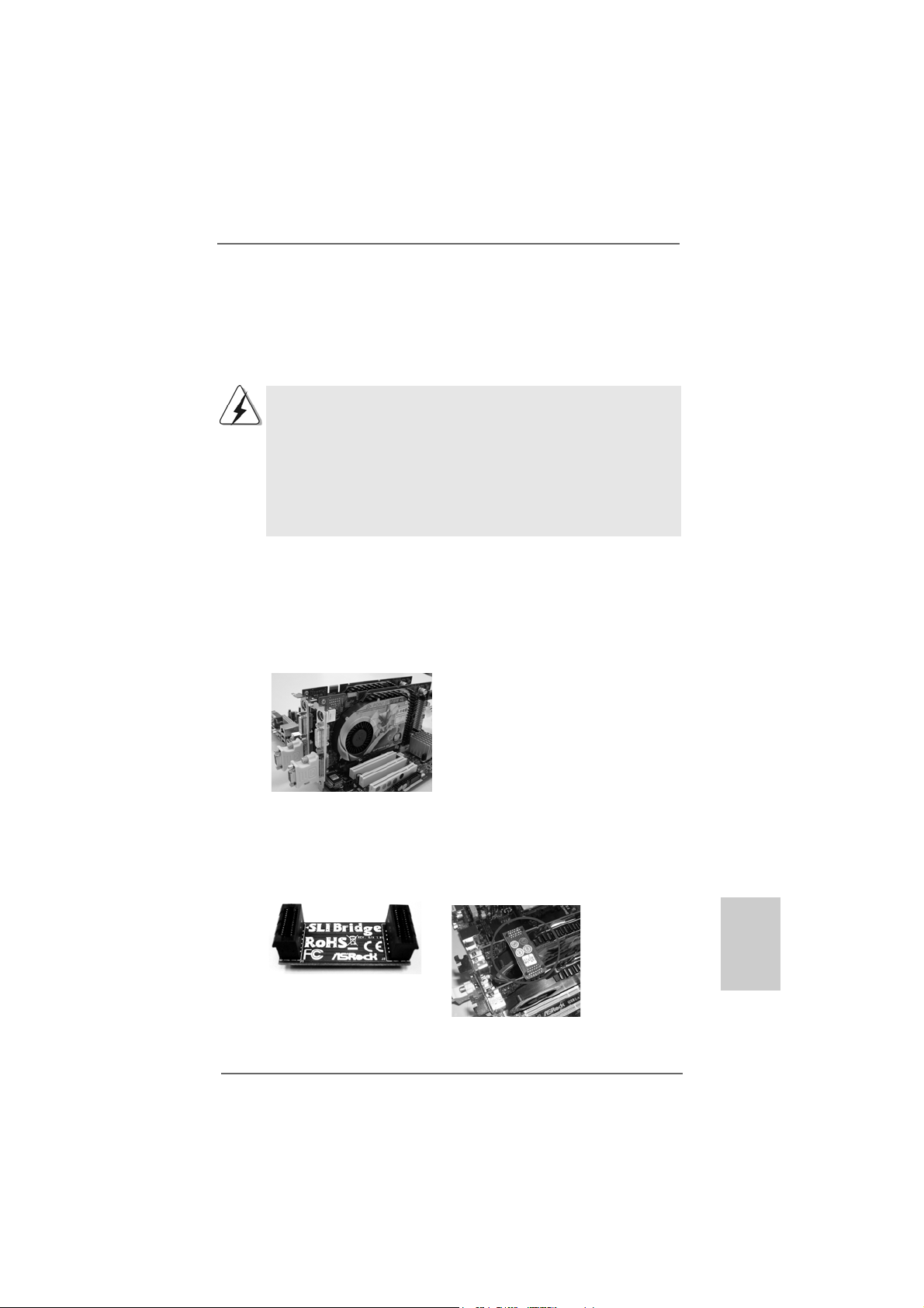
Step 1. Install the identical SLITM-ready graphics cards that are NVIDIA® certified
because different types of graphics cards will not work together properly.
(Even the GPU chips version shall be the same.) Insert one graphics card
into PCIE2 slot and a nother graphics card to PCIE4 slot. Make sure that the
cards are properly seated on the slots.
TM
Step2. If required, connect an auxiliary power source to the PCI Express graphics
cards.
Step3. Align and insert the SLI Bridge to the goldfingers on each graphics card.
Make sure that the SLI Bridge is firmly in place.
ASRock ALiveNF5SLI-1394 Motherboard
1515
15
1515
EnglishEnglish
EnglishEnglish
English
Page 16
Step4. Connect a VGA cable or a DVI-I cable to the monitor connector and the DVI
connector of the graphics card that is inserted to PCIE2 slot.
Step5. Connect a 4-pin ATX power cable to SLI/XFIRE power connector.
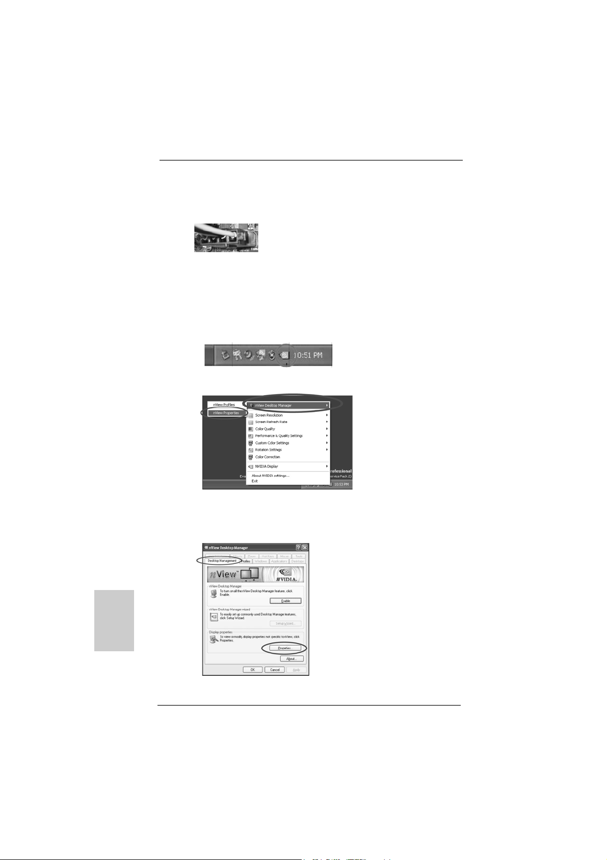
Step6. Install the graphics card drivers to your system. After that, you can enable
the Multi-Graphics Processing Unit (GPU) feature in the NVIDIA® nView
system tray utility. Please follow the below procedures to enable the multiGPU feature.
For Windows® XP / XP 64-bit OS:
A. Click the NVIDIA Settings icon on your Windows® taskbar.
B. From the pop-up menu, select nView Desktop Manager, and then
click nView Properties.
English
EnglishEnglish
EnglishEnglish
1616
16
1616
C. From the nView Desktop Manager window, select the Desktop
Management tab.
D. Click Properties to display the Display Properties dialog box.
ASRock ALiveNF5SLI-1394 Motherboard
Page 17
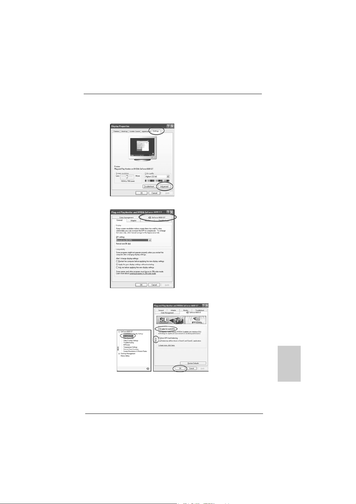
E. From the Display Properties dialog box, sele ct the Settings ta b then click
Advanced.
F. Select the NVIDIA GeForce tab.
G. Click the slider to display the following screen, then select the SLI
multi-GPU item.
H. Click the Enable SLI multi-GPU check box.
I. Click OK when done.
ASRock ALiveNF5SLI-1394 Motherboard
1717
17
1717
EnglishEnglish
EnglishEnglish
English
Page 18
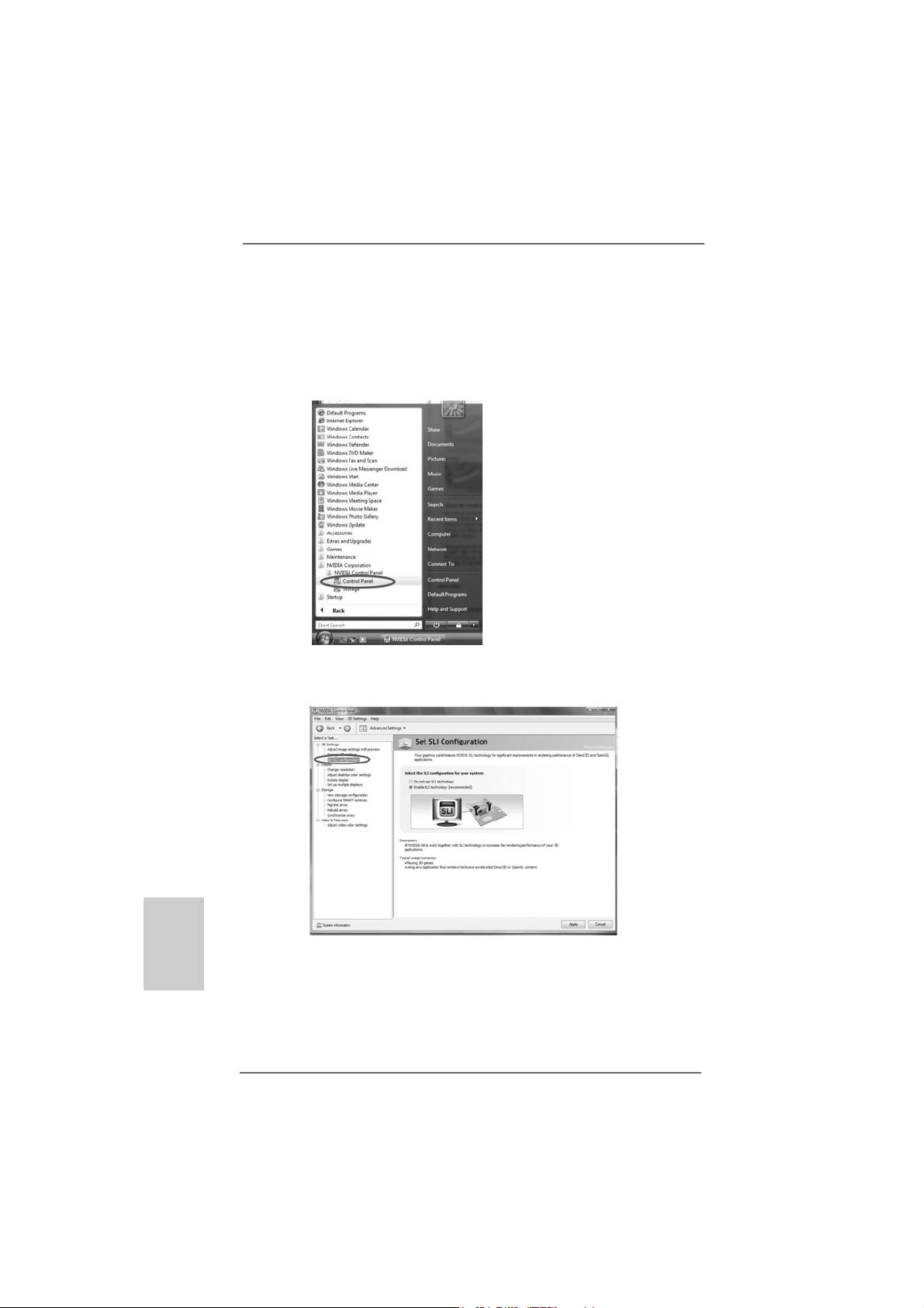
For Windows® VistaTM / VistaTM 64-bit OS:
A. Click the Start icon on your Windows taskbar.
B. From the pop-up menu, select All Programs, and then click NVIDIA
Corporation.
C. Select NVIDIA Control Panel tab.
D. Select Control Panel tab.
E. From the pop-up menu, select Set SLI configuration, and then click
Apply.
English
EnglishEnglish
EnglishEnglish
1818
18
1818
* SLITM appearing here is a registered trademark of NVIDIA® Technologies Inc., and is used only
for identification or explanation and to the owners’ benefit, without intent to infringe.
ASRock ALiveNF5SLI-1394 Motherboard
Page 19
2.62.6
Jumpers SetupJumpers Setup
2.6
Jumpers Setup
2.62.6
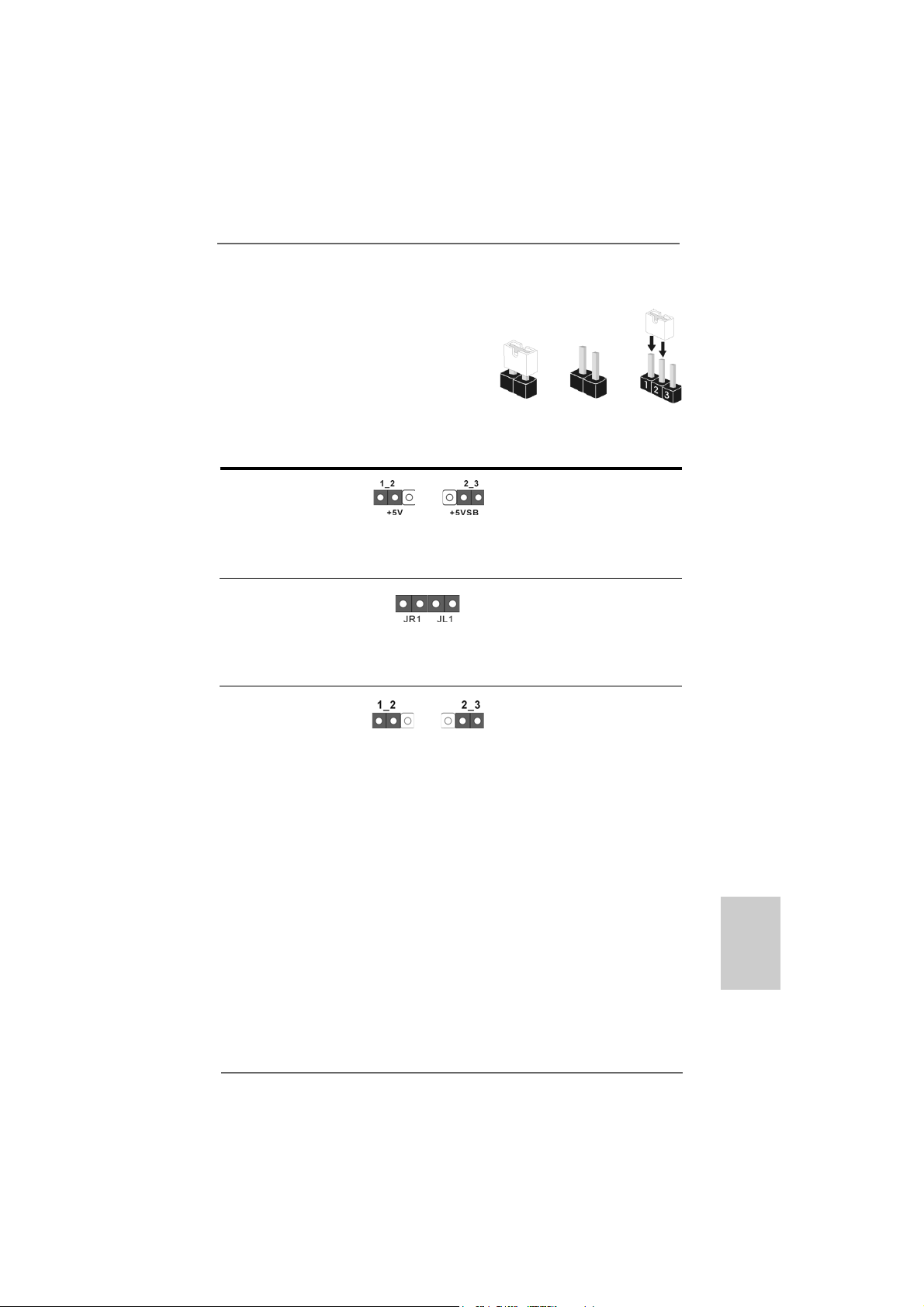
Jumpers SetupJumpers Setup
The illustration shows how jumpers are
setup. When the jumper cap is placed on
pins, the jumper is “Short”. If no jumper cap
is placed on pins, the jumper is “Open”. The
illustration shows a 3-pin jumper whose pin1
and pin2 are “Short” when jumper cap is
placed on these 2 pins.
Jumper Setting
PS2_USB_PW1 Short pin2, pin3 to enable
(see p.2, No. 1) +5VSB (standby) for PS/2 or
USB wake up events.
Note: To select +5VSB, it requires 2 Amp and higher standby current provided by
power supply.
JR1 JL1 Jumper
(see p.2, No. 28)
Note: If the jumpers JL1 and JR1 are short, both the front panel and the rear panel
audio connectors can work.
Clear CMOS Jumper
(CLRCMOS1)
(see p.2, No. 17)
Clear CMOSDefault
OpenShort
Note: CLRCMOS1 allows you to clear the data in CMOS. The data in CMOS includes
system setup information such as system password, date, time, and system
setup parameters. To clear and reset the system parameters to default setup,
please turn off the computer and unplug the power cord from the power
supply. After waiting for 15 seconds, use a jumper cap to short pin2 and pin3
on CLRCMOS1 for 5 seconds. However, please do not clear the CMOS right
after you update the BIOS. If you need to clear the CMOS when you just finish
updating the BIOS, you must boot up the system first, and then shut it down
before you do the clear-CMOS action.
ASRock ALiveNF5SLI-1394 Motherboard
1919
19
1919
EnglishEnglish
EnglishEnglish
English
Page 20
2.7 Onboard Headers and Connectors2.7 Onboard Headers and Connectors
2.7 Onboard Headers and Connectors
2.7 Onboard Headers and Connectors2.7 Onboard Headers and Connectors
Onboard headers and connectors are NOT jumpers. Do NOT place
jumper caps over these headers and connectors. Placing jumper caps
over the headers and connectors will cause permanent damage of the
motherboard!
•
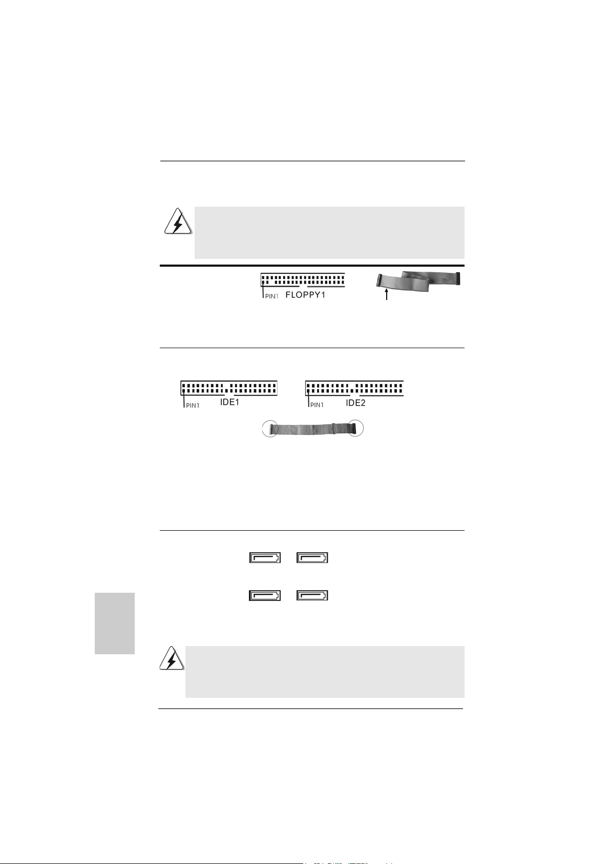
Floppy Connector
(33-pin FLOPPY1)
(see p.2, No. 25)
the red-striped side to Pin1
Note: Make sure the red-striped side of the cable is plugged into Pin1 side of the
connector.
Primary IDE Connector (Blue) Secondary IDE Connector (Black)
(39-pin IDE1, see p.2 No. 1 1) (39-pin IDE2, see p.2 No. 10)
English
EnglishEnglish
EnglishEnglish
2020
20
2020
connect the blue end
to the motherboard
80-conductor ATA 66/100/133 cable
connect the black end
to the IDE devices
Note: If you use only one IDE device on this motherboard, please set the IDE
device as “Master”. Please refer to the instruction of your IDE device vendor
for the details. Besides, to optimize compatibility and performance, please
connect your hard disk drive to the primary IDE connector (IDE1, blue) and
CD-ROM to the secondary IDE connector (IDE2, black).
Serial A T AII Connectors These four Seri al A T AII (SAT AII)
(SAT AII_BLACK (PORT 1.0): connectors support SATA data
see p.2, No. 12) cables for internal storage
(SAT AII_ORANGE (PORT 1.1): devices. The current SATAII
see p.2, No. 13) interface allows up to 3.0 Gb/s
(SAT AII_BLUE (PORT 2.0): data transfer rate.
see p.2, No. 15)
(SAT AII_RED (PORT 2.1):
see p.2, No. 14)
SATAII_RED (PORT 2.1) connector can be used for internal storage
device or be connected to eSATAII_TOP connector to support eSATAII
device. Please read “eSATAII Interface Introduction” on page 26 for
details about eSATAII and eSATAII installation procedure s.
SAT AII_BLUE
(PORT 2.0)
SAT AII_RED
(PORT 2.1)
SAT AII_BLACK
(PORT 1.0)
SATAII_ORANGE
(PORT 1.1)
ASRock ALiveNF5SLI-1394 Motherboard
Page 21
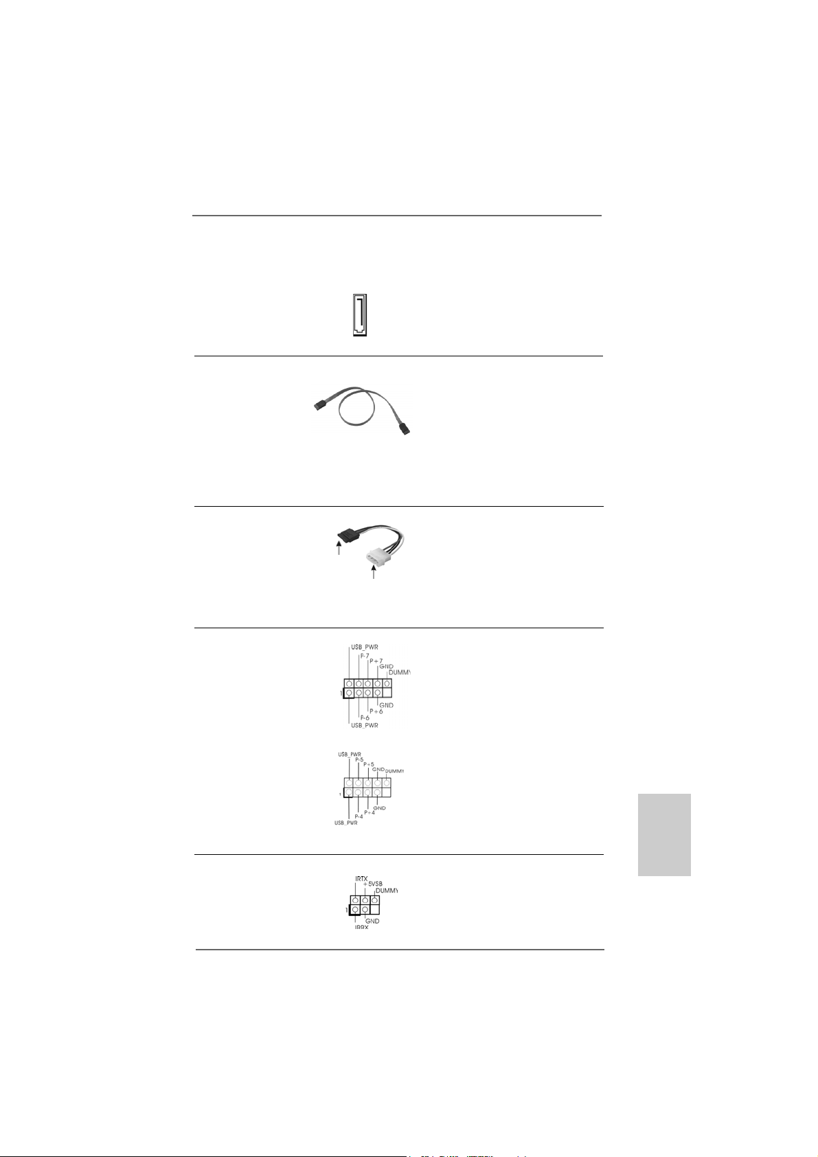
eSATAII Connector This eSATAII connector
(eSAT AII_TOP: see p.2, No. 37) supports SATA data cable for
external SATAII function. The
current eSATAII interface
allows up to 3.0 Gb/s data
eSATAII_TOP
transfer rate.
Serial A TA (SA TA) Either end of the SATA data ca ble
Data Cable can be connected to the SATA /
(Optional) SATAII hard disk or the SATAII
connector on this motherboard.
You can also use the SATA data
cable to connect SATAII_RED
(PORT 2.1) connector and
eSATAII connector.
Serial ATA (SATA) Please connect the black end of
Power Cable SATA power cable to the power
(Optional) connector on each drive. Then
connect to the SAT A
HDD power connector
connect to the
power supply
connect the white end of SATA
power cable to the power
connector of the power supply.
USB 2.0 Headers Besides four default USB 2.0
(9-pin USB6_7) ports on the I/O panel, there are
(see p.2 No. 18) two USB 2.0 headers on this
motherboard. Each USB 2.0
header cansupport two USB
2.0 ports.
(9-pin USB4_5)
(see p.2 No. 19)
Infrared Module Header This header supports an
(5-pin IR1) optional wireless transmitting
(see p.2, No. 23) and receiving infrared module.
ASRock ALiveNF5SLI-1394 Motherboard
2121
21
2121
EnglishEnglish
EnglishEnglish
English
Page 22
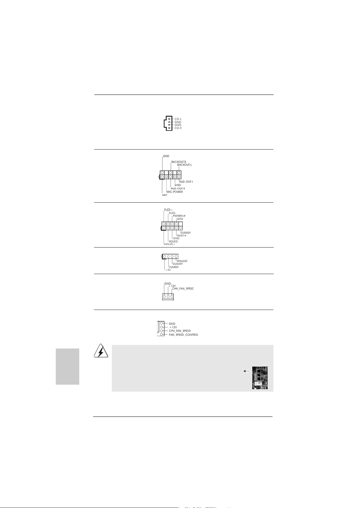
Internal Audio Connectors This connector allows you
(4-pin CD1) to receive stereo audio input
(CD1: see p.2, No. 29) from sound sources such as
CD1
a CD-ROM, D VD-ROM, TV
tuner card, or MPEG card.
Front Panel Audio Header This is an interface for front
(8-pin AUDIO1) panel audio cable that allows
(see p.2 No. 27) convenient connection and
control of audio devices.
System Panel Header This header accommodates
(9-pin PANEL1) several system front panel
(see p.2, No. 22) functions.
Chassis Speaker Header Please connect the chassis
(4-pin SPEAKER 1) speaker to this header.
(see p.2, No. 21)
Chassis Fan Connector Please connect a chassis fan
(3-pin CHA_FAN1) cable to this connector and
(see p.2, No. 20) match the black wire to the
ground pin.
English
EnglishEnglish
EnglishEnglish
2222
22
2222
CPU Fan Connector Please connect the CPU fan
(4-pin CPU_FAN1) cable to this connector and
(see p.2, No. 36) match the black wire to the
Though this motherboard provides 4-Pin CPU fan (Quiet Fan) support, the 3-Pin
CPU fan still can work successfully even without the fan speed control function.
If you plan to connect the 3-Pin CPU fan to the CPU fan connector on this
motherboard, please connect it to Pin 1-3.
1
2
3
4
ground pin.
Pin 1-3 Connected
3-Pin Fan Installation
ASRock ALiveNF5SLI-1394 Motherboard
Page 23
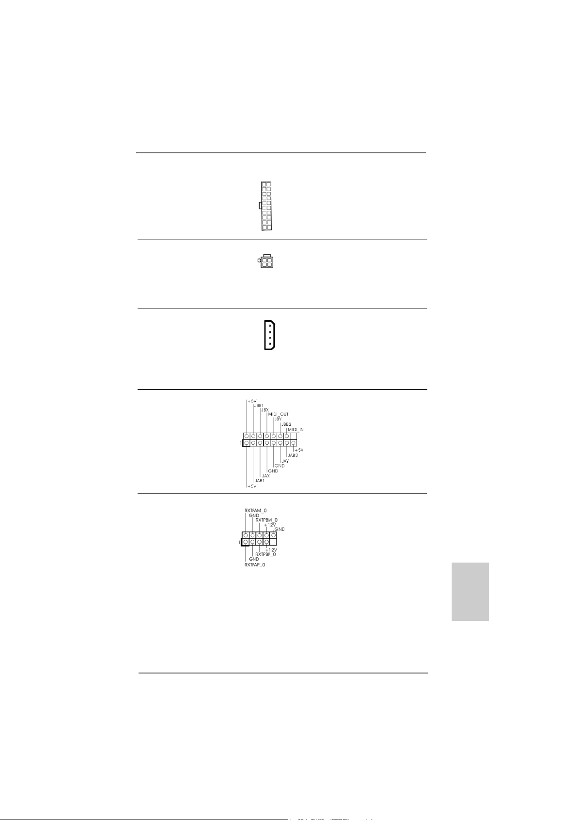
ATX Power Connector Please connect an ATX power
(20-pin ATXPW R1) supply to this connector.
(see p.2, No. 2)
ATX 12V Power Connector Please note that it is necessary
(4-pin A TX12V1) to connect a power supply with
(see p.2, No. 7) ATX 12V plug to this connector.
Failing to do so will cause power
up failure.
SLI/XFIRE Power Connector It is not necessary to use this
(4-pin SLI/XFIRE_POWER1) connector, but please connect it
(see p.2 No. 3) with a hard disk power connecor
SLI/XFIRE_POWER1
when two graphics cards are
plugged to this motherboard at
the same ti me.
Game Port Hea der Connect a Game cable to this
(15-pin GAME1) header if the Game port bracket
(see p.2 No. 26) is installed.
IEEE 1394 Header Besides one default IEEE 1394
(9-pin FRONT_1394) port on the I/O panel, there is one
(see p.2 No. 24) IEEE 1394 header
(FRONT_1394) on this
motherboard. This IEEE 1394
header cansupport one IEEE
1394 port.
d
2323
23
2323
EnglishEnglish
EnglishEnglish
English
ASRock ALiveNF5SLI-1394 Motherboard
Page 24
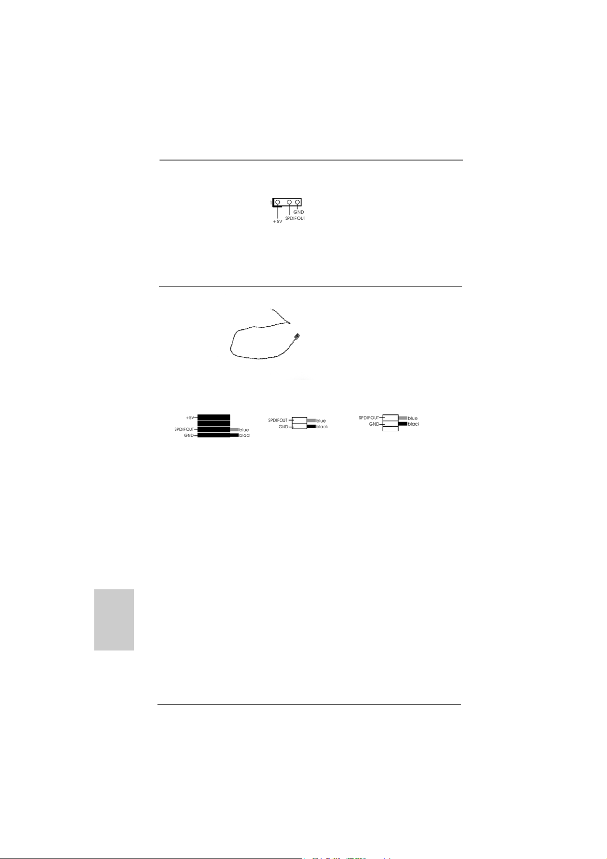
HDMI_SPDIF Header HDMI_SPDIF header, providing
(3-pin HDMI_SPDIF1) SPDIF audio output to HDMI V GA
(see p.2, No. 31) card, allows the system to
connect HDMI Digital TV/
projector/LCD devices. Please
connect the HDMI_SPDIF
connector of HDMI VGA card to
this header.
HDMI_SPDIF Cable Please connect the bla ck end (A)
(Optional) of HDMI_SPDIF cable to the
C
B
A
HDMI_SPDIF header on the
motherboard. Then connect the
white end (B or C) of
HDMI_SPDIF cable to the
HDMI_SPDIF connector of HDMI
VGA card.
A. black end B. white end (2-pin) C. white end (3-pin)
English
EnglishEnglish
EnglishEnglish
2424
24
2424
ASRock ALiveNF5SLI-1394 Motherboard
Page 25
2.8 HDMI_SPDIF Header Connection Guide2.8 HDMI_SPDIF Header Connection Guide
2.8 HDMI_SPDIF Header Connection Guide
2.8 HDMI_SPDIF Header Connection Guide2.8 HDMI_SPDIF Header Connection Guide
HDMI (High-Definition Multi-media Interface) is an all-digital audio/video specification,
which provides an interface between any compatible digital audio/video source,
such as a set-top box, DVD player, A/V receiver and a compatible digital audio or
video monitor, such as a digital television (DTV). A complete HDMI system requires a
HDMI VGA card and a HDMI ready motherboard with a HDMI_SPDIF header. This
motherboard is equipped with a HDMI_SPDIF header, which provides SPDIF audio
output to HDMI VGA card, allows the system to connect HDMI Digital TV/projector/
LCD devices. To use HDMI function on this motherboard, please carefully follow the
below steps.
•
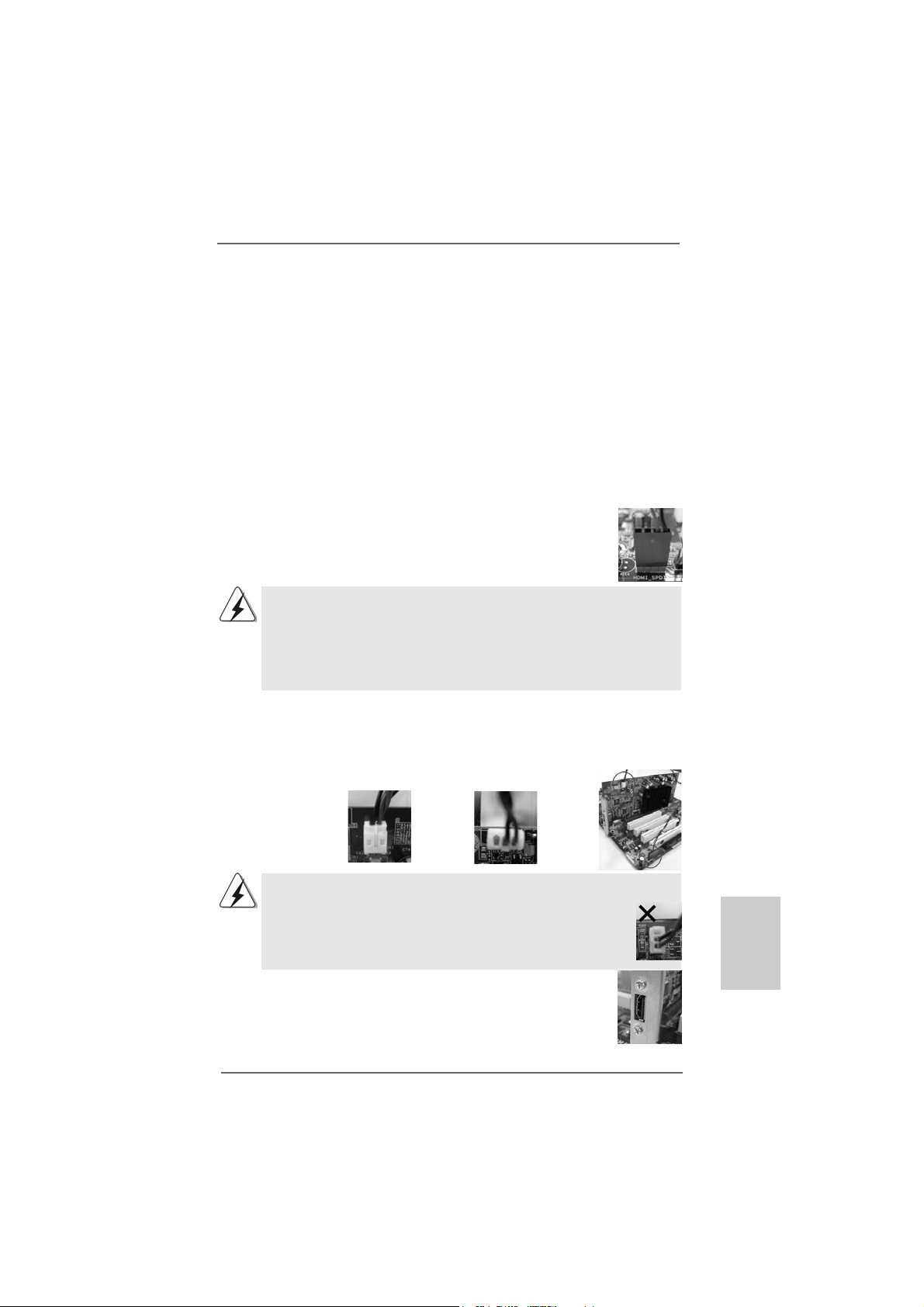
Step 1. Install the HDMI VGA card to the PCI Express Graphics slot on this
motherboard. For the proper installation of HDMI VGA card, please refer
to the installation guide on page 14.
Step 2. Connect the black end (A) of HDMI_SPDIF cable to the
HDMI_SPDIF header (HDMI_SPDIF1, yellow, see page 2,
No. 31) on the motherboard.
Make sure to correctly connect the HDMI_SPDIF cable to the motherboard and the
HDMI VGA card according to the same pin definition. For the pin definition of
HDMI_SPDIF header and HDMI_SPDIF cable conne ctors, ple ase refer to page 24. For
the pin definition of HDMI_SPDIF connectors on HDMI VGA card, please refer to the
user manual of HDMI VGA card vendor. Incorrect connection may cause permanent
damage to this motherboard and the HDMI VGA card.
Step 3. Connect the white end (B or C) of HDMI_SPDIF cable to the HDMI_SPDIF
connector of HDMI VGA card. (There are two white ends (2-pin and 3-pin)
on HDMI_SPDIF cable. Please choose the appropriate white end according
to the HDMI_SPDIF connector of the HDMI V GA card you install.
white end
(2-pin) (B)
Please do not connect the white end of HDMI_SPDIF cable to the wrong connector
of HDMI VGA card or other VGA card. Otherwise, the motherboard and the
VGA card may be damaged. For example, this picture shows the wrong
example of connecting HDMI_SPDIF cable to the fan connector of PCI
Express VGA card. Please refer to the VGA card user manual for
connector usage in advance.
white end
(3-pin) (C)
Step 4. Connect the HDMI output connector on HDMI VGA card to
HDMI device, such as HDTV. Please refer to the user manual
of HDTV and HDMI VGA card vendor for detailed connection
procedures.
Step 5. Install HDMI VGA card driver to your system.
ASRock ALiveNF5SLI-1394 Motherboard
2525
25
2525
EnglishEnglish
EnglishEnglish
English
Page 26

English
EnglishEnglish
EnglishEnglish
2.9 eSA2.9 eSA
2.9 eSA
2.9 eSA2.9 eSA
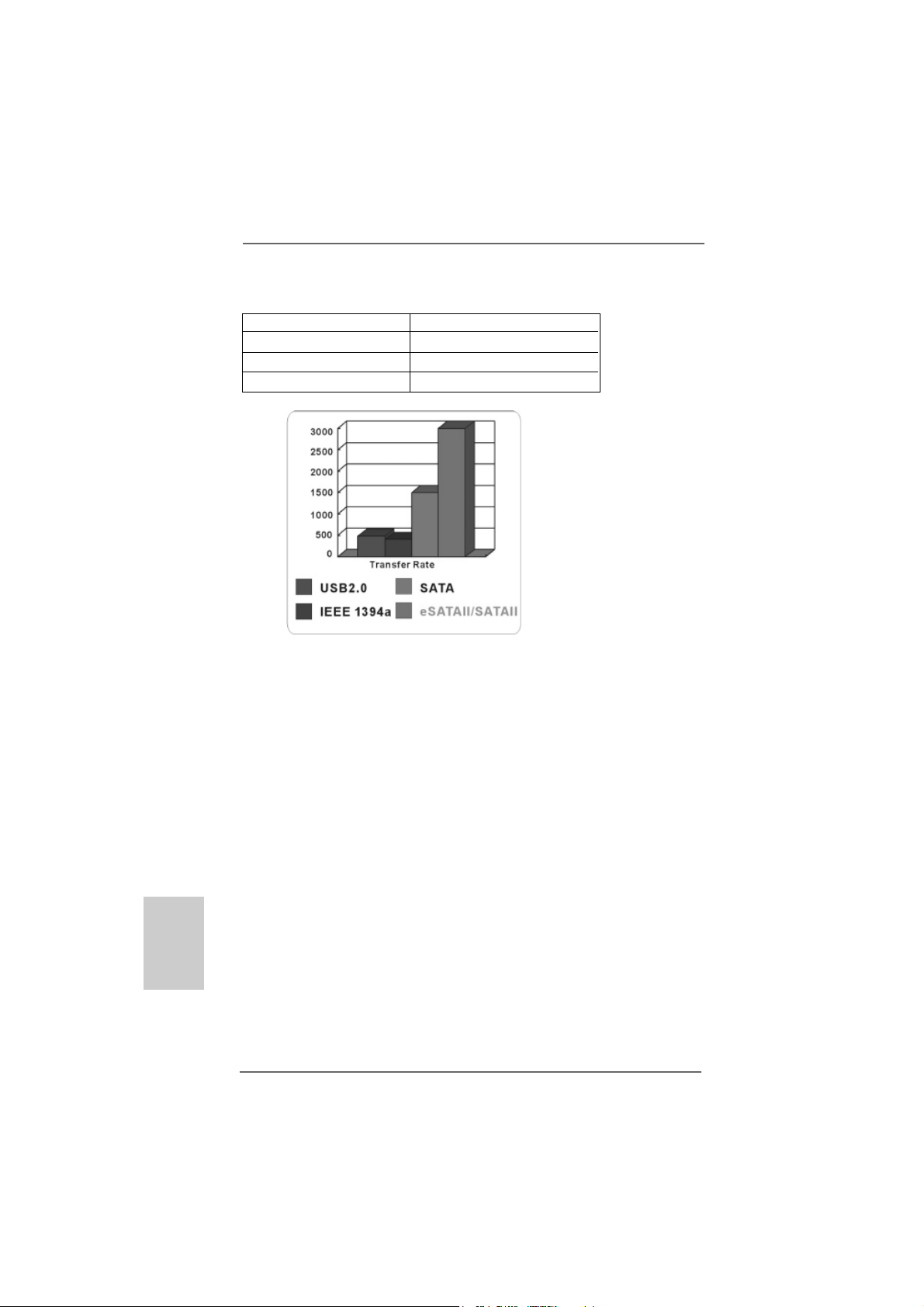
What is eSATAII?
This motherboard supports eSATAII interface, the external SATAII specification.
eSATAII allows you to enjoy the SATAII function provided by the I/O of your
computer, offering the high speed data transfer rate up to 3.0Gb/s, and the
convenient mobility like USB. eSATAII is equipped with Hot Plug capability that
enables you to exchange drives easily. For example, with eSATAII interface, you
may simply plug your eSATAII hard disk to the eSATAII ports instead of opening
your chassis to exchange your SATAII hard disk. Currently, on the market, the
data transfer rate of USB 2.0 is up to 480Mb/s, and for IEEE 1394 is up to 400Mb/
s. However, eSATAII provides the data transfer rate up to 3000Mb/s, which is
much higher than USB 2.0 and IEEE 1394, and still keeps the convenience of Hot
Plug feature. Therefore, on the basis of the advantageous transfer speed and the
facilitating mobile capability, in the near future, eSATAII will replace USB 2.0 and
IEEE 1394 to be a trend for external interface.
TT
AII InterAII Inter
T
AII Inter
TT
AII InterAII Inter
NOTE:
1. If you set “SATA Operation Mode” option in BIOS setup to RAID mode and enable the
option “eSATAII Support”, Hot Plug function is supported with eSATAII devices.
Therefore, you can insert or remove your eSATAII devices to the eSATAII ports while
the system is power-on and in working condition.
2. If you set “SATA Operation Mode” option in BIOS setup to non-RAID mode, Hot Plug
function is not supported with eSATAII devices. If you still want to use eSATAII
function in non-RAID mode, please insert or remove your eSATAII devices to the
eSATAII ports only when the system is power-off.
3. If you want to use the eSATAII HDD as an OS disk, please set “SATA Operation Mode”
option in BIOS setup to non-RAID mode. If you want to use the eSATAII HDD as a
removable data disk, please set “SATA Operation Mode” option in BIOS setup to RAID
mode and enable the option “eSATAII Support”. If you want to add the eSATAII HDD
as a RAID disk, please set “SATA Operation Mode” option in BIOS setup to RAID
mode and disable the option “eSATAII Support”.
4. Please refer to page 32 to 34 for detailed information of RAID mode and non-RAID
mode.
face Introductionface Introduction
face Introduction
face Introductionface Introduction
2626
26
2626
ASRock ALiveNF5SLI-1394 Motherboard
Page 27
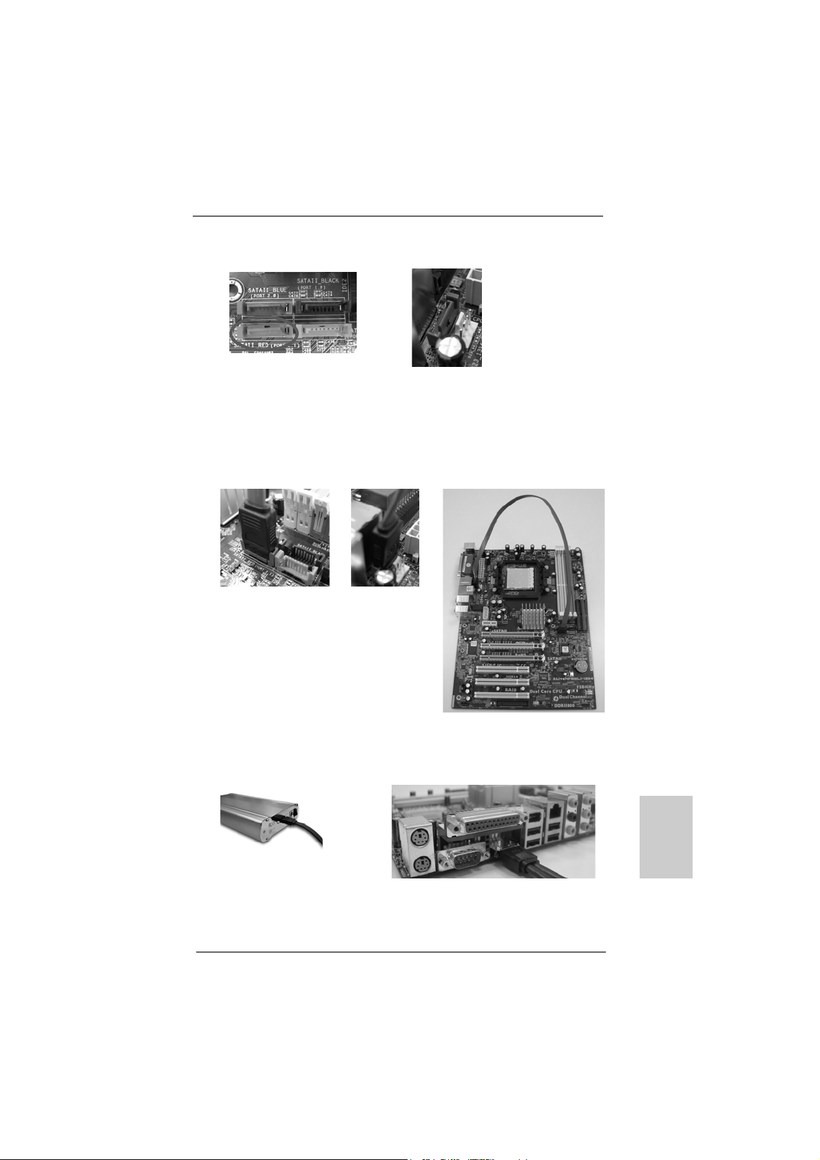
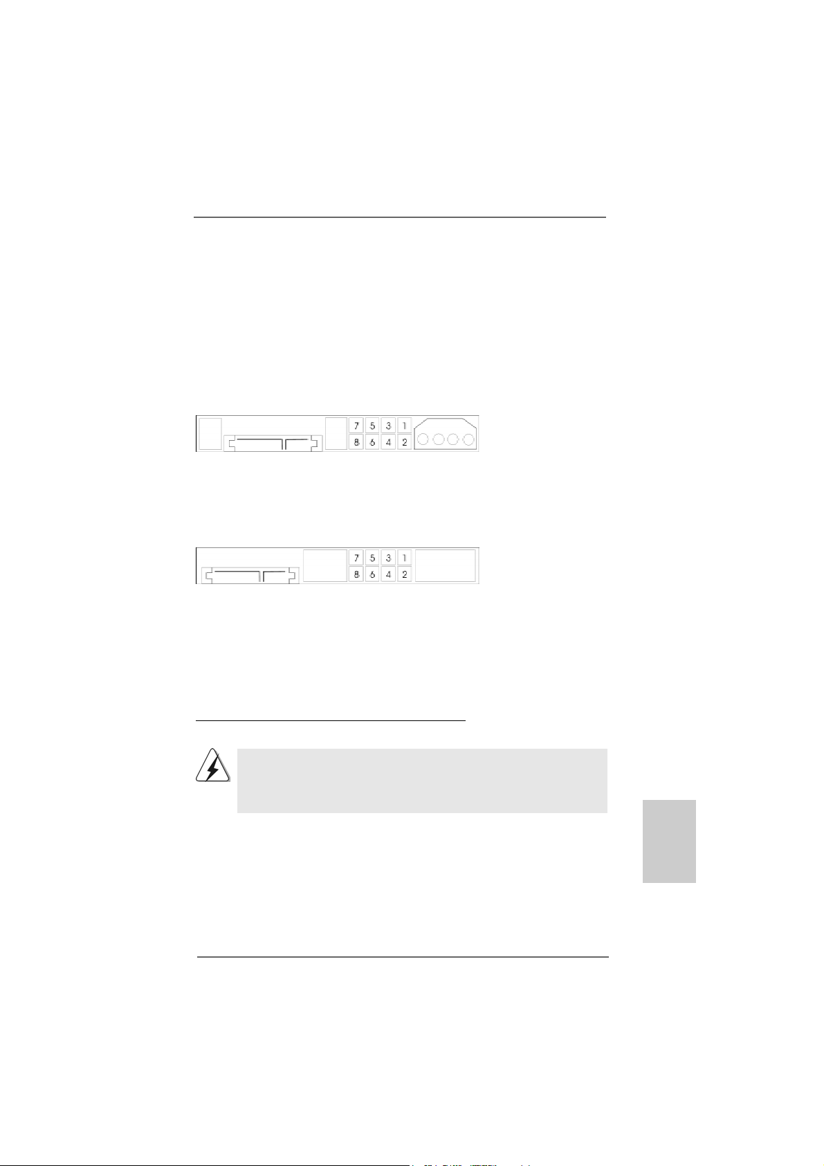
How to install eSATAII?
SATAII connector
SATAII_RED (PORT 2.1)
eSATAII connector
(eSATAII_TOP)
1. In order to enable the eSATAII port of the I/O shield, you need to connect the
red SATAII connector (SATAII_RED (PORT 2.1); see p.2 No.14) and the
eSATAII connector (eSATAII_TOP; see p.2 No.37) with a SATA data cable
first.
Connect the SATA data
cable to the red SATAII
connector
(SATAII_RED (POR T 2.1))
Connect the SATA
data cable to the
eSATAII connector
(eSATAII_TOP)
2. Use the eSATAII device cable to connect eSATAII device and the eSATAII port
of the I/O shield.
Connect one end of the eSATAII
device cable to eSATAII device
ASRock ALiveNF5SLI-1394 Motherboard
Connect the other end of the eSATAII
device cable to eSATAII port of the I/O
shield
2727
27
2727
EnglishEnglish
EnglishEnglish
English
Page 28
Comparison between eSATAII and other devices
IEEE 1394 400Mb/s
USB 2.0 480Mb/s
SATA 1.5Gb/s (1500Mb/s)
eSATAII/SA TAII 3.0Gb/s (3000Mb/s)
English
EnglishEnglish
EnglishEnglish
2828
28
2828
ASRock ALiveNF5SLI-1394 Motherboard
Page 29
2.102.10
SASA
TT
2.10
2.102.10
Before installing SATAII hard disk to your computer, please carefully read below
SATAII hard disk setup guide. Some default setting of SATAII hard disks may not be
at SATAII mode, which operate with the best performance. In order to enable SATAII
function, please follow the below instruction with different vendors to correctly
adjust your SA TAII hard disk to SATAII mode in advance; otherwise, your SATAII hard
disk may fail to run at SATAII mode.
Western Digital
If pin 5 and pin 6 are shorted, SATA 1.5Gb/s will be enabled.
On the other hand, if you want to enable SATAII 3.0Gb/s, please remove the jumpers
from pin 5 and pin 6.
SAMSUNG
If pin 3 and pin 4 are shorted, SATA 1.5Gb/s will be enabled.
On the other hand, if you want to enable SATAII 3.0Gb/s, please remove the jumpers
from pin 3 and pin 4.
AII Hard Disk Setup GuideAII Hard Disk Setup Guide
SA
T
AII Hard Disk Setup Guide
SASA
TT
AII Hard Disk Setup GuideAII Hard Disk Setup Guide
HITACHI
Please use the Feature Tool, a DOS-bootable tool, for changing various A TA feature s.
Please visit HITACHI’s website for details:
http://www.hitachigst.com/hdd/support/download.htm
The above examples are just for your reference. For different SATAII hard
disk products of different vendors, the jumper pin setting methods may not
be the same. Please visit the vendors’ website for the updates.
ASRock ALiveNF5SLI-1394 Motherboard
2929
29
2929
EnglishEnglish
EnglishEnglish
English
Page 30
2.112.11
Serial ASerial A
2.11
Serial A
2.112.11
Serial ASerial A
InstallationInstallation
Installation
InstallationInstallation
This motherboard adopts NVIDIA® nForce 560 SLI chipset that supports Serial ATA
(SATA) / Serial AT AII (SAT AII) hard disk s a nd RAID functions. You may install SA TA /
SATAII hard disks on this motherboard for internal storage devices. This se ction will
guide you to install the SA TA / SATAII hard disks.
STEP 1: Install the SATA / SATAII hard disks into the drive bays of your chassis.
STEP 2: Connect the SATA power cable to the SATA / SATAII hard disk.
STEP 3: Connect one end of the SATA data cable to the motherboard’s SATAII
connector.
STEP 4: Connect the other end of the SATA data cable to the SATA / SATAII hard
disk.
TT
A (SAA (SA
TT
T
A (SA
TT
A (SAA (SA
1. If you plan to use RAID 0, RAID 1 or JBOD function, you need to install
at least 2 SATA / SATAII hard disks. If you plan to use RAID 5 function,
you need to install 3 SATA / SATAII hard disks. If you plan to use
RAID 0+1 function, you need to install 4 SATA / SATAII hard disks.
2. It is recommended to build RAID on internal SATAII ports. In other words,
if SATAII_RED (PORT 2.1) is used for eSATAII port, please build RAID on
other SATAII ports.
A) / Serial AA) / Serial A
T
A) / Serial A
TT
A) / Serial AA) / Serial A
TT
AII (SAAII (SA
T
AII (SA
TT
AII (SAAII (SA
TT
AII) Hard DisksAII) Hard Disks
T
AII) Hard Disks
TT
AII) Hard DisksAII) Hard Disks
English
EnglishEnglish
EnglishEnglish
3030
30
3030
ASRock ALiveNF5SLI-1394 Motherboard
Page 31

2.12 Hot Plug and Hot Swap F2.12 Hot Plug and Hot Swap F
2.12 Hot Plug and Hot Swap F
2.12 Hot Plug and Hot Swap F2.12 Hot Plug and Hot Swap F
HDDs and eSAHDDs and eSA
HDDs and eSA
HDDs and eSAHDDs and eSA
This motherboard supports Hot Plug and Hot Swap functions for SATA / SATAII /
eSATAII Devices in RAID mode.
NOTE
What is Hot Plug Function?
If the SATA / SATAII HDDs are NOT set for RAID configuration, it is called
“Hot Plug” for the action to insert and remove the SATA / SATAII HDDs
while the system is still power-on and in working condition.
However, please note that it cannot perform Hot Plug if the OS has been
installed into the SATA / SATAII HDD.
What is Hot Swap Function?
If SATA / SATAII HDDs are built as RAID1 or RAID 5 then it is called “Hot
Swap” for the action to insert and remove the SATA / SATAII HDDs while
the system is still power-on and in working condition.
eSATAII is equipped with Hot Plug capability that enables you to exchange
drives easily. For example, with eSATAII interface, you may simply plug your
eSATAII devices to the eSATAII ports instead of opening your chassis to
exchange your SATAII hard disk.
TT
AII DevicesAII Devices
T
AII Devices
TT
AII DevicesAII Devices
unctions for SAunctions for SA
unctions for SA
unctions for SAunctions for SA
TT
A / SAA / SA
T
A / SA
TT
A / SAA / SA
TT
T
TT
AIIAII
AII
AIIAII
Hot Plug and Hot Swap functions are not supported under Windows® Vista
and VistaTM 64-bit OS.
ASRock ALiveNF5SLI-1394 Motherboard
TM
EnglishEnglish
EnglishEnglish
English
3131
31
3131
Page 32

2.132.13
Driver Installation GuideDriver Installation Guide
2.13
Driver Installation Guide
2.132.13
Driver Installation GuideDriver Installation Guide
To install the drivers to your system, please insert the support CD to your optical
drive first. Then, the drivers compatible to your system can be auto-detected and
listed on the support CD driver page. Please follow the order from up to bottom
side to install those required drivers. Therefore, the drivers you install can work
properly.
2.142.14
Installing WindowsInstalling Windows
2.14
Installing Windows
2.142.14
Installing WindowsInstalling Windows
TMTM
TM
/ Vista/ Vista
/ Vista
/ Vista/ Vista
If you just want to install Windows® 2000, Windows® XP, Windows® XP 64-bit,
Windows® VistaTM or Windows® VistaTM 64-bit on your SATA / SATAII HDDs without
RAID functions, you don’t have to make a SATA / SATAII driver diskette. Besides,
there is no need for you to change the BIOS setting. You can start to in stall Windows
2000, Windows® XP, Windows® XP 64-bit, Windows® VistaTM or Windows® Vista
64-bit on your system directly.
2.152.15
Installing WindowsInstalling Windows
2.15
Installing Windows
2.152.15
Installing WindowsInstalling Windows
/ Vista/ Vista
/ Vista
/ Vista/ Vista
TMTM
64-bit Without RAID Functions 64-bit Without RAID Functions
64-bit Without RAID Functions
64-bit Without RAID Functions 64-bit Without RAID Functions
Before installing Windows® 2000 to your system, your Windows® 2000 optical disk
is supposed to include SP4. If there is no SP4 included in your disk, please visit
below website for proper procedures of making a SP4 disk:
http://www.microsoft.com/Windows2000/downloads/servicepacks/sp4/spdeploy.
htm#the_integrated_installation_fmay
TMTM
TM
TMTM
64-bit With RAID Functions 64-bit With RAID Functions
64-bit With RAID Functions
64-bit With RAID Functions 64-bit With RAID Functions
Before installing Windows® 2000 to your system, your Windows® 2000 optical disk
is supposed to include SP4. If there is no SP4 included in your disk, please visit
below website for proper procedures of making a SP4 disk:
http://www.microsoft.com/Windows2000/downloads/servicepacks/sp4/spdeploy.
htm#the_integrated_installation_fmay
®
2000 / XP / XP 64-bit / Vista 2000 / XP / XP 64-bit / Vista
2000 / XP / XP 64-bit / Vista
2000 / XP / XP 64-bit / Vista 2000 / XP / XP 64-bit / Vista
®
2000 / XP / XP 64-bit / Vista 2000 / XP / XP 64-bit / Vista
2000 / XP / XP 64-bit / Vista
2000 / XP / XP 64-bit / Vista 2000 / XP / XP 64-bit / Vista
TMTM
TM
TMTM
TMTM
TM
TMTM
®
TM
English
EnglishEnglish
EnglishEnglish
3232
32
3232
If you want to install Windows® 2000, Windows® XP, Windows® XP 64-bit, Windows
VistaTM or Windows® VistaTM 64-bit OS on your SATA / SATAII HDDs with RAID
functions, please follow below procedures according to the OS you install.
ASRock ALiveNF5SLI-1394 Motherboard
®
Page 33

2.15.1 Installing Windows2.15.1 Installing Windows
2.15.1 Installing Windows
2.15.1 Installing Windows2.15.1 Installing Windows
Functions Functions
Functions
Functions Functions
If you want to install Windows® 2000, Windows® XP or Windows® XP 64-bit on your
SATA / SATAII HDDs with RAID functions, please follow below steps.
STEP 1: Make a SATA / SATAII Driver Diskette.
A. Insert the ASRock Support CD into your optical drive to boot your system.
B. During POST at the beginning of system boot-up, press <F11> key, and
then a window for boot devices selection appears. Please select CDROM as the boot device.
C. When you see the message on the screen, “Generate Serial ATA driver
diskette [YN]?”, press <Y>.
D. Then you will see these messages,
Please insert a blank
formatted diskette into floppy
drive A:
press any key to start
Please insert a floppy diskette into the floppy drive, and press any key.
E. The system will start to format the floppy diskette and copy SATA /
SATAII drivers into the floppy diskette.
STEP 2: Set Up BIOS.
A. Enter BIOS SETUP UTILITY Advanced screen IDE Configuration.
B. Set the “SATA Operation Mode” option to [RAID].
STEP 3: Use “RAID Installation Guide” to set RAID configuration.
Before you start to configure RAID function, you need to check the RAID installation
guide in the Support CD for proper configuration. Please refer to the BIOS RAID
installation guide in the following path in the Support CD:
.. \ RAID Installation Guide
STEP 4: Install Windows® 2000 / Windows® XP / Windows® XP 64-bit OS on
your system.
After step 1, 2, 3, you can start to install Windows® 2000 / Windows® XP / Windows
XP 64-bit OS on your system. At the beginning of Windows® setup, press F6 to install
a third-party RAID driver. When prompted, insert the SATA / SATAII driver diskette
containing the NVIDIA® RAID driver. After reading the floppy disk, the driver will be
presented. Select the driver to install according to the mode you choose and the OS
you install.
NOTE. If you install Windows® 2000 / Windows® XP / Windows® XP 64-bit on IDE
HDDs and want to manage (create, convert, delete, or rebuild) RAID functions
on SATA / SATAII HDDs, you still need to set up “SATA Operation Mode” to [RAID]
in BIOS first. Then, please set the RAID configuration by using the Windows RAID
installation guide in the following path in the Support CD:
.. \ RAID Installation Guide
ASRock ALiveNF5SLI-1394 Motherboard
®
2000 / XP / XP 64-bit With RAID 2000 / XP / XP 64-bit With RAID
2000 / XP / XP 64-bit With RAID
2000 / XP / XP 64-bit With RAID 2000 / XP / XP 64-bit With RAID
®
EnglishEnglish
EnglishEnglish
English
3333
33
3333
Page 34

Vista Vista
Vista
Vista Vista
TM TM
TM
TM TM
/ Vista/ Vista
/ Vista
/ Vista/ Vista
OS)
TM
64-bit OS)
®
2.15.2 Installing Windows2.15.2 Installing Windows
2.15.2 Installing Windows
2.15.2 Installing Windows2.15.2 Installing Windows
RAID Functions RAID Functions
RAID Functions
RAID Functions RAID Functions
If you want to install Windows® VistaTM or Windows® VistaTM 64-bit on your SATA /
SATAII HDDs with RAID functions, please follow below steps.
STEP 1: Set Up BIOS.
A. Enter BIOS SETUP UTILITY Advanced screen IDE Configuration.
B. Set the “SATA Operation Mode” option to [RAID].
STEP 2: Use “RAID Installation Guide” to set RAID configuration.
Before you start to configure RAID function, you need to check the RAID installation
guide in the Support CD for proper configuration. Please refer to the BIOS RAID
installation guide part of the document in the following path in the Support CD:
.. \ RAID Installation Guide
STEP 3: Install Windows® VistaTM / Windows® VistaTM 64-bit OS on your
system.
Insert the Windows® VistaTM / Windows® VistaTM 64-bit optical disk into the optical
drive to boot your system, and follow the instruction to install Windows® VistaTM /
Windows® VistaTM 64-bit OS on your system. When you see “Where do you want to
install Windows?” page, please insert the ASRock Support CD into your optical drive,
and click the “Load Driver” button on the left on the bottom to load the NVIDIA® RAID
drivers. NVIDIA® RAID drivers are in the following path in our Support CD:
.. \ I386 (For Windows® Vista
.. \ AMD64 (For Windows® Vista
After that, please insert Windows® VistaTM / Windows® VistaTM 64-bit optical disk into
the optical drive again to continue the installation.
TM
TMTM
TM
TMTM
64-bit With 64-bit With
64-bit With
64-bit With 64-bit With
English
EnglishEnglish
EnglishEnglish
3434
34
3434
NOTE. If you install Windows® VistaTM / Windows® VistaTM 64-bit on IDE HDDs and want to
manage (create, convert, delete, or rebuild) RAID functions on SATA / SATAII HDDs,
you still need to set up “SATA Operation Mode” to [RAID] in BIOS first. Then, please set
the RAID configuration by using the Windows RAID installation guide in the following
path in the Support CD:
.. \ RAID Installation Guide
2.162.16
Untied Overclocking TUntied Overclocking T
2.16
Untied Overclocking T
2.162.16
Untied Overclocking TUntied Overclocking T
This motherboard supports Untied Overclocking Technology, which means during
overclocking, FSB enjoys better margin due to fixed PCI / PCIE buses. Before you
enable Untied Overclocking function, please enter “Overclock Mode” option of BIOS
setup to set the selection from [Auto] to [CPU, PCIE, Async.]. Therefore, CPU FSB is
untied during overclocking, but PCI / PCIE buses are in the fixed mode so that FSB can
operate under a more stable overclocking environment.
Please refer to the warning on page 7 for the possible overclocking risk before
you apply Untied Overclocking Technology.
ASRock ALiveNF5SLI-1394 Motherboard
echnologyechnology
echnology
echnologyechnology
Page 35

3. BIOS Information3. BIOS Information
3. BIOS Information
3. BIOS Information3. BIOS Information
The Flash Memory on the motherboard stores BIOS Setup Utility. When you start up
the computer, please press <F2> during the Power-On-Self-Test (POST) to enter
BIOS Setup utility; otherwise, POST continues with its test routines. If you wish to
enter BIOS Setup after POST, please restart the system by pressing <Ctl> + <Alt> +
<Delete>, or pressing the reset button on the system chassis. The BIOS Setup
program is designed to be user-friendly. It is a menu-driven program, which allows
you to scroll through its various sub-menus and to select among the predetermined
choices. For the detailed information about BIOS Setup, please refer to the User
Manual (PDF file) contained in the Support CD.
4. Software Suppor4. Software Suppor
4. Software Suppor
4. Software Suppor4. Software Suppor
This motherboard supports various Microsoft® Windows® operating systems: 2000 /
XP / XP Media Center / XP 64-bit / VistaTM / VistaTM 64-bit. The Support CD that came
with the motherboard contains necessary drivers and useful utilities that will enhance motherboard features. To begin using the Support CD, insert the CD into your
CD-ROM drive. It will display the Main Menu automatically if “AUTORUN” is enabled in
your computer. If the Main Menu does not appear automatically, locate and doubleclick on the file “ASSETUP.EXE” from the “BIN” folder in the Support CD to display the
menus.
t CD informationt CD information
t CD information
t CD informationt CD information
EnglishEnglish
EnglishEnglish
English
ASRock ALiveNF5SLI-1394 Motherboard
3535
35
3535
Page 36

3636
36
3636
ASRock ALiveNF5SLI-1394 Motherboard
Page 37

™
‘ ’ ™
®
®
®
ASRock ALiveNF5SLI-1394 Motherboard
®
3737
37
3737
Page 38

3838
38
3838
®
®
ASRock ALiveNF5SLI-1394 Motherboard
Page 39

® ®
®
®
®
ASRock ALiveNF5SLI-1394 Motherboard
3939
39
3939
Page 40

®
®
®
®
®
®
®
®
®
®
4040
40
4040
ASRock ALiveNF5SLI-1394 Motherboard
Page 41

ASRock ALiveNF5SLI-1394 Motherboard
4141
41
4141
Page 42

4242
42
4242
ASRock ALiveNF5SLI-1394 Motherboard
Page 43

DDRII_1 DDRII_2 DDRII_3 DDRII_4
( )( )( )( )
(1) - (2) - -
(3)
ASRock ALiveNF5SLI-1394 Motherboard
4343
43
4343
Page 44

4444
44
4444
ASRock ALiveNF5SLI-1394 Motherboard
Page 45

®
ASRock ALiveNF5SLI-1394 Motherboard
4545
45
4545
Page 46

®
® ®
®
®
® ®
®
4646
46
4646
ASRock ALiveNF5SLI-1394 Motherboard
Page 47

®
®®
®
®®
®
ASRock ALiveNF5SLI-1394 Motherboard
4747
47
4747
Page 48

4848
48
4848
ASRock ALiveNF5SLI-1394 Motherboard
Page 49

®®
®
®®
®
®
ASRock ALiveNF5SLI-1394 Motherboard
4949
49
4949
Page 50

5050
50
5050
ASRock ALiveNF5SLI-1394 Motherboard
Page 51

“ ”
SAT AII_BLUE
(PORT 2.0)
SAT AII_RED
(PORT 2.1)
SAT AII_BLACK
(PORT 1.0)
SATAII_ORANGE
(PORT 1.1)
ASRock ALiveNF5SLI-1394 Motherboard
5151
51
5151
Page 52

eSATAII_TOP
5252
52
5252
ASRock ALiveNF5SLI-1394 Motherboard
Page 53

CD1
1
2
3
4
ASRock ALiveNF5SLI-1394 Motherboard
5353
53
5353
Page 54

SLI/XFIRE_POWER1
5454
54
5454
ASRock ALiveNF5SLI-1394 Motherboard
Page 55

C
B
A
ASRock ALiveNF5SLI-1394 Motherboard
5555
55
5555
Page 56

5656
56
5656
ASRock ALiveNF5SLI-1394 Motherboard
Page 57

ASRock ALiveNF5SLI-1394 Motherboard
5757
57
5757
Page 58

5858
58
5858
ASRock ALiveNF5SLI-1394 Motherboard
Page 59

IEEE 1394 400Mb/s
USB 2.0 480Mb/s
SATA 1.5Gb/s (1500Mb/s)
eSATAII/SA TAII 3.0Gb/s (3000Mb/s)
ASRock ALiveNF5SLI-1394 Motherboard
5959
59
5959
Page 60

6060
60
6060
ASRock ALiveNF5SLI-1394 Motherboard
Page 61

®
ASRock ALiveNF5SLI-1394 Motherboard
6161
61
6161
Page 62

6262
62
6262
®
ASRock ALiveNF5SLI-1394 Motherboard
Page 63

®
®
®
®
®
®
®
®
®
®
®
®
®
®
®
®
®
®
®
®
®
®
®
6363
63
6363
ASRock ALiveNF5SLI-1394 Motherboard
Page 64

®
® ®
® ® ®
®
®
® ®
®
®
®
®
6464
64
6464
ASRock ALiveNF5SLI-1394 Motherboard
Page 65

®
®
®
® ®
®
®
®
®
®
®
®
ASRock ALiveNF5SLI-1394 Motherboard
6565
65
6565
Page 66

® ®
6666
66
6666
ASRock ALiveNF5SLI-1394 Motherboard
Page 67

O:
X:
X O O O O O
X O O O O O
ASRock ALiveNF5SLI-1394 Motherboard
6767
67
6767
Page 68

1. Einführung1. Einführung
1. Einführung
1. Einführung1. Einführung
Wir danken Ihnen für den Kauf des ASRock ALiveNF5SLI-1394 Motherboard, ein
zuverlässiges Produkt, welches unter den ständigen, strengen Qualitätskontrollen
von ASRock gefertigt wurde. Es bietet Ihnen exzellente Leistung und robustes Design,
gemäß der Verpflichtung von ASRock zu Qualität und Halbarkeit.
Diese Schnellinstallationsanleitung führt in das Motherboard und die schrittweise
Installation ein. Details über das Motherboard finden Sie in der Bedienungsanleitung
auf der Support-CD.
Da sich Motherboard-Spezifikationen und BIOS-Software verändern können,
kann der Inhalt dieses Handbuches ebenfalls jederzeit geändert werden. Für
den Fall, dass sich Änderungen an diesem Handbuch ergeben, wird eine neue
Version auf der ASRock-Website, ohne weitere Ankündigung, verfügbar sein.
Die neuesten Grafikkarten und unterstützten CPUs sind auch auf der
ASRock-Website aufgelistet.
ASRock-Website: http://www.asrock.com
1.1 Kartoninhalt
ASRock ALiveNF5SLI-1394 Motherboard
(ATX-Formfaktor: 30.5 cm x 22.9 cm; 12.0 Zoll x 9.0 Zoll)
Ein ASRock SLI-Brücke
ASRock ALiveNF5SLI-1394 Schnellinstallationsanleitung
ASRock ALiveNF5SLI-1394 Support-CD
Ein 80-adriges Ultra-ATA 66/100/133 IDE-Flachbandkabel
Ein Flachbandkabel für ein 3,5-Zoll-Diskettenlaufwerk
Zwei Serial ATA (SATA) -Datenkabel (optional)
Ein Serial ATA (SATA) -Festplattenstromkabel (optional)
Ein HDMI_SPDIF-Kabel (Option)
Ein “ASRock 1394_eSATAII I/O Plus” I/O Shield
Deutsch
DeutschDeutsch
DeutschDeutsch
6868
68
6868
ASRock ALiveNF5SLI-1394 Motherboard
Page 69

1.21.2
SpezifikationenSpezifikationen
1.2
Spezifikationen
1.21.2
SpezifikationenSpezifikationen
Plattform - ATX-Formfaktor: 30.5 cm x 22.9 cm; 12.0 Zoll x 9.0 Zoll
CPU - AM2 Sockel, unterstützt AMD AthlonTM 64FX / 64X2 / X2 / 64
und Sempron Prozessoren
- AMD LIVE!TM-bereit
- Unterstützt Cool ‘n’ QuietTM-Technologie von AMD
- FSB 1000 MHz (2.0 GT/s)
- Unterstützt Untied-Übertaktungstechnologie
(siehe VORSICHT 1)
- Unterstützt Hyper-Transport-Technologie
Chipsatz - NVIDIA® nForce 560 SLI
Speicher - Unterstützung von Dual-Kanal-Speichertechnologie
(siehe VORSICHT 2)
- 4 x Steckplätze für DDRII
- Unterstützt DD RII800/667/533
- Max. 8GB (siehe VORSICHT 3)
Hybrid Booster - Schrittloser CPU-Frequenz-Kontrolle (siehe VORSICHT 4)
- ASRock U-COP (siehe VORSICHT 5)
- Boot Failure Guard (B.F.G. – Systemstartfehlerschutz)
- ASRock AM2 Boost: ASRocks patentgeschützte Technologie
zur Erhöhung der Arbeitsspeicherleistung um bis zu 12,5%
(siehe VORSICHT 6)
Erweiterungs- - 1 x PCI Express x16-Steckplätze (Weiß)
steckplätze - 2 x PCI Express x8-Steckplätze (Gelb; nur für NVIDIA® SLITM)
- 1 x PCI Express x1-Steckplätze
- 3 x PCI -Steckplätze
- Unterstützt NVIDIA® SLI
Audio - 7.1-Kanal-Windows® VistaTM Premium Level Superior Audio
(C-Media CM6501 Audiocodec mit UAA-Architektur)
LAN - Gigabit LAN 10/100/1000 Mb/s
- Giga PHY Realtek RTL8211B
- Unterstützt Wake-On-LAN
E/A-Anschlüsse ASRock 1394_eSATAII I/O Plus
an der - 1 x PS/2-Mausanschluss
Rückseite - 1 x PS/2-Tastaturanschluss
- 1 x Serieller port: COM 1
- 1 x Paralleler port: Unterstützung für ECP / EPP
- 4 x Standard-USB 2.0-Anschlüsse
- 1 x eSATAII Port
- 1 x RJ-45 Port
ASRock ALiveNF5SLI-1394 Motherboard
TM
(siehe VORSICHT 7)
6969
69
6969
DeutschDeutsch
DeutschDeutsch
Deutsch
Page 70

Deutsch
DeutschDeutsch
DeutschDeutsch
- 1 x IEEE 1394 Port
- HD Audiobuchse: Lautsprecher seitlich / Lautsprecher hinten
/ Mitte/Bass / Audioeingang/ Lautsprecher vorne / Mikrofon
(siehe VORSICHT 8)
Anschlüsse - 4 x SATAII-Anschlüsse, unterstützt bis 3.0 Gb/s
Datenübertragungsrate, unterstützt RAID (RAID 0, RAID 1,
RAID 0+1, JBOD, RAID 5), NCQ und “Hot Plug” Funktionen
(siehe VORSICHT 9)
- 1 x eSATAII 3.0 GB/s-An schlüsse (mit 1 SATAII-Anschlüssen
geteilt), unterstützt NCQ und „Hot Plug“-Funktion
(siehe VORSICHT 10)
- 2 x ATA133 IDE-Anschlüsse (Unterstützt bis 4 IDE-Geräte)
- 1 x FDD-Anschlüsse
- 1 x Infrarot-Modul-Header
- 1 x Game-Anschluss
- 1 x HDMI_SPDIF-Anschluss
- 1 x IEEE 1394-Anschlussleisten
- CPU/Gehäuse-Lüfteranschluss
- 20-pin ATX-Netz-Header
- 4-pin anschluss für 12V-ATX-Netzteil
- SLI/XFIRE-Netz-Header
- Interne Audio-Anschlüsse
- Anschluss für Audio auf der Gehäusevorderseite
- 2 x USB 2.0-Anschlüsse (Unterstützung 4
zusätzlicher USB 2.0-Anschlüsse) (siehe VORSICHT 11)
BIOS - 4Mb AMI BIOS
- AMI legal BIOS mit Unterstützung für “Plug and Play”
- ACPI 1.1-Weckfunktionen
- JumperFree-Modus
- SMBIOS 2.3.1
Support-CD - Treiber, Dienstprogramme, Antivirussoftware
(Probeversion)
Hardware Monitor - Interner CPU-Temperatursensor
- CPU-Umgebungstemperatursensor
- Motherboardtemperaturerkennung
- Drehzahlmessung für CPU-Lüfter
- Drehzahlmessung für Gehäuselüfter
- CPU-Lüftergeräuschdämpfung
- Spannungsüberwachung: +12V, +5V, +3.3V, Vcore
7070
70
7070
ASRock ALiveNF5SLI-1394 Motherboard
Page 71

Betriebssysteme - Unterstützt Microsoft® Windows® 2000 / XP / XP Media
Center / XP 64-Bit / VistaTM / Vista
TM
64-Bit
(siehe VORSICHT 12)
Zertifizierungen - FCC, CE, WHQL
WARNUNG
Beachten Sie bitte, dass Overclocking, einschließlich der Einstellung im BIOS, Anwenden
der Untied Overclocking-Technologie oder Verwenden von Overclocking-Werkzeugen von
Dritten, mit einem gewissen Risiko behaftet ist. Overclocking kann sich nachteilig auf die
Stabilität Ihres Systems auswirken oder sogar Komponenten und Geräte Ihres Systems
beschädigen. Es geschieht dann auf eigene Gefahr und auf Ihre Kosten. Wir übernehmen
keine Verantwortung für mögliche Schäden, die aufgrund von Overclocking verursacht
wurden.
VORSICHT!
1. Dieses Motherboard unterstützt die Untied-Übertaktungstechnologie.
Unter “Entkoppelte Übertaktungstechnologie” auf Seite 99 finden Sie
detaillierte Informationen.
2. Dieses Motherboard unterstützt Dual-Kanal-Speichertechnologie. Vor
Implementierung der Dual-Kanal-Speichertechnologie müssen Sie die
Installationsanleitung für die Speichermodule auf Seite 75 zwecks richtiger
Installation gelesen haben.
3. Durch Betriebssystem-Einschränkungen kann die tatsächliche
Speichergröße weniger als 4 GB betragen, da unter Windows® XP und
Windows® Vista™ etwa s Speicher zur Nutzung durch das System reserviert
wird. Unter Windows® XP 64-bit und Windows® Vista™ 64-bit mit 64-Bit-CPU
besteht diese Einschränkung nicht.
4. Obwohl dieses Motherboard stufenlose Steuerung bietet, wird
Overclocking nicht empfohlen. Frequenzen, die von den empfohlenen
CPU-Busfrequenzen abweichen, können Instabilität des Systems
verursachen oder die CPU beschädigen.
5. Wird eine Überhitzung der CPU registriert, führt das System einen
automatischen Shutdown durch. Bevor Sie das System neu starten, prüfen
Sie bitte, ob der CPU-Lüfter am Motherboard richtig funktioniert, und
stecken Sie bitte den Stromkabelstecker aus und dann wieder ein. Um die
Wärmeableitung zu verbessern, bitte nicht vergessen, etwas
Wärmeleitpaste zwischen CPU und Kühl körper zu sprühen.
6. Dieses Motherboard unterstützt die ASRock AM2 Boost
Übertaktungstechnologie. Wenn Sie diese Funktion im BIOS-Setup
aktivieren, wird die Arbeitsspeicherleistung um bis zu 12,5% gesteigert. Die
Wirkung hängt aber von der verwendeten AM2 CPU ab. Diese Funktion
übertaktet die Standardfrequenz des Chipsatz und der CPU. Dennoch
gewähren wir die Systemstabilität nicht bei allen CPU/DRAMKonfigurationen. Wird Ihr System nach dem Aktivieren der AM2 BoostFunktion unstabil, dann ist diese Funktion wahrscheinlich nicht für Ihr
System geeignet. Sie können diese Funktion deaktivieren, um die Stabilität
Ihres System zu bewahren.
ASRock ALiveNF5SLI-1394 Motherboard
7171
71
7171
DeutschDeutsch
DeutschDeutsch
Deutsch
Page 72

7. Dieses Motherboard unterstützt die NVIDIA® SLITM-T echnologie. Die PCIE2-
und PCIE4-Steckplätze (gelb) sind für die SLITM-Funktion vorgesehen.
Sofern Sie nur eine PCI Express-VGA-Karte in diesem Motherboard
einsetzen möchten, installieren Sie diese bitte im PCIE3-Steckplatz.
Informationen zu SLITM-Modus-kompatiblen PCI Express-VGA-Karten finden
Sie unter „Unterstützte PCI Express-VGA-Karten für den SLITM-Modus“ auf
Seite 9. Hinweise zur richtigen Installation von PCI Express-VGA-Karten
finden Sie in der Installationsanleitung auf Seite 77.
8. Der Mikrofoneingang dieses Motherboards unterstützt Stereo- und
Mono-Modi. Der Audioausgang dieses Motherboards unterstützt 2Kanal-, 4-Kanal-, 6-Kanal- und 8-Kanal-Modi. Stellen Sie die richtige
Verbindung anhand der Tabelle auf Seite 3 her.
9. Bevor Sie eine SATA II Festplatte mit dem SATA II Anschluss verbinden,
lesen Sie bitte die “Anleitung zur SATA II Festplatteneinrichtung“ auf
Seite 93, um Ihre SATA II Festplatte in den SATA II Modus umzuschalten.
SATA-Festplatten können Sie auch direkt mit dem SATA II-Anschluss
verbinden.
10. Dieses Motherboard unterstützt die eSATAII-Schnittstelle, externe
SATAII-Spezifikation. Bitte lesen Sie den Abschnitt „Vorstellung der
eSATAII-Schnittstelle“ auf Seite 90. Dort finden Sie detaillierte
Informationen über eSATAII und zur eSATAII-Installation.
11. Das Power Management für USB 2.0 arbeitet unter Microsoft® Windows
VistaTM 64-Bit / VistaTM / XP 64-Bit / XP SP1 oder SP2/2000 SP4
einwandfrei.
12. Der Microsoft® Windows® VistaTM / VistaTM 64-Bit Treiber wird ständig
aktualisiert. Sobald wir den neuesten Treiber haben, stellen wir ihn auf
unserer Website zur Verfügung. Bitte besuchen Sie unsere Website für
den Microsoft® Windows® VistaTM / VistaTM 64-Bit Treiber und verwandte
Informationen.
ASRock-Website http://www.asrock.com
®
Deutsch
DeutschDeutsch
DeutschDeutsch
7272
72
7272
1.31.3
Minimale Hardwarevorausetzungen für WindowsMinimale Hardwarevorausetzungen für Windows
1.3
Minimale Hardwarevorausetzungen für Windows
1.31.3
Minimale Hardwarevorausetzungen für WindowsMinimale Hardwarevorausetzungen für Windows
TMTM
TM
TMTM
VistaVista
Vista
VistaVista
Premium 2007 und Basic Logo Premium 2007 und Basic Logo
Premium 2007 und Basic Logo
Premium 2007 und Basic Logo Premium 2007 und Basic Logo
Systemintegratoren und Anwender unseres Motherboards, die ihre
Rechner auf die Vergabe des Windows® VistaTM Premium 2007 und Basic Logos vorbereiten möchten, finden die minimalen
hardwarevoraussetzungen in der folgenden Tabelle.
CPU Sempron 2800+
Speicher 1 GB Systemspeicher (Premium)
VGA DX9.0 mit WDDM-Treiber
mit 128 Bit-VGA-Speicher (Pre mium)
mit 64 Bit-VGA-Speicher (Basic)
ASRock ALiveNF5SLI-1394 Motherboard
®
Page 73

* Nach dem ersten Juni, 2007 sind , all Windows® VistaTM Systems dafür erforderlich,
mit der Minimalforderung der obengenannte Hardware übereinzustimmen, um
Windows® VistaTM Premium 2007 logo.zu befähigen.
* Für den Windows® VistaTM-Logotest sollte der Betriebssystem-eigene Audiotreiber
zum Testen der Audiofunktionalität verwendet werden.
2. Installation2. Installation
2. Installation
2. Installation2. Installation
Dies ist ein Motherboard mit einem ATX-Formfaktor (12,0 Zoll x 9,0 Zoll, 30,5 cm x
22,9 cm). Vor Installation des Motherboards müssen Sie die Konfiguration Ihres
Gehäuses dahingehend überprüfen, ob das Motherboard dort hineinpasst.
Sicherheitshinweise vor der MontageSicherheitshinweise vor der Montage
Sicherheitshinweise vor der Montage
Sicherheitshinweise vor der MontageSicherheitshinweise vor der Montage
Bitte nehmen Sie die folgende Sicherheitshinweise zur Kenntnis, bevor Sie
das Motherboard einbauen oder Veränderungen an den Einstellungen
vornehmen.
Vor dem Ein- oder Ausbauen einer Komponent müssen Sie sicherstellen, dass
der Netzschalter ausgeschaltet oder die Netzleitung von der Steckdose
abgezogen ist. Andernfalls könnten das Motherboard, Peripheriegeräte und/oder
Komponenten schwer beschädigt werden.
1. Trennen Sie das System vom Stromnetz, bevor Sie eine
Systemkomponente berühren, da es sonst zu schweren Schäden
am Motherboard oder den sonstigen internen, bzw. externen
Komponenten kommen kann.
2. Um Schäden aufgrund von statischer Elektrizität zu vermeiden,
das Motherboard NIEMALS auf einen Teppich o.ä.legen. Denken Sie
außerem daran, immer ein geerdetes Armband zu tragen oder ein
geerdetes Objekt aus Metall zu berühren, bevor Sie mit
Systemkomponenten hantieren.
3. Halten Sie Komponenten immer an den Rändern und vermeiden Sie
Berührungen mit den ICs.
4. Wenn Sie Komponenten ausbauen, legen Sie sie immer auf eine
antistatische Unterlage, oder zurück in die Tüte, mit der die
Komponente geliefert wurde.
5. Wenn Sie das Motherboard mit den Schrauben an dem
Computergehäuse befestigen, überziehen Sie bitte die Schrauben
nicht! Das Motherboard kann sonst beschädigt werden.
DeutschDeutsch
DeutschDeutsch
Deutsch
ASRock ALiveNF5SLI-1394 Motherboard
7373
73
7373
Page 74

2.1 CPU Installation2.1 CPU Installation
2.1 CPU Installation
2.1 CPU Installation2.1 CPU Installation
Schritt 1: Öffnen Sie den CPU-Sockel, indem sie den Hebel leicht zur Seite und
dann nach oben ziehen, auf einen Winkel von 90°.
Schritt 2: Positionieren Sie die CPU genau so über dem Sockel, dass sich die
Ecke der CPU mit dem goldenen Dre ieck exakt über der Ecke des
Sockels befindet, die mit einem kleinen Dreieck gekennzeichnet ist.
Schritt 3: Drücken Sie die CPU vorsichtig in den Sockel.
Die CPU sollte problemlos in den Sockel passen. Drücken Sie die CPU
nicht mit Gewalt in den Sockel, damit sich die Pins nicht verbiegen.
Überprüfen Sie die Ausrichtung und suchen nach verbogenen Pins,
sollte die CPU nicht in den Sockel passen.
Schritt 4: Wenn die CPU korrekt im Sockel sitzt, leicht mit dem Finger
draufdrücken und gleichzeitig den Hebel nach unten drücken, bis er
hörbar einrastet.
Deutsch
DeutschDeutsch
DeutschDeutsch
Hebel 90°
nach oben
SCHRITT 1:
Ziehen Sie den
Sockelhebel hoch
2.22.2
Installation des CPU-Lüfters und des KühlkörpersInstallation des CPU-Lüfters und des Kühlkörpers
2.2
Installation des CPU-Lüfters und des Kühlkörpers
2.22.2
Installation des CPU-Lüfters und des KühlkörpersInstallation des CPU-Lüfters und des Kühlkörpers
Goldenes Dreieck
der CPU
Kleines Dreieck
der Sockelecke
SCHRITT 2 / SCHRITT 3:
Richten Sie das goldene
Dreieck der CPU mit dem
kleinen Dreieck der
Sockelecke aus
SCHRITT 4:
Drücken Sie den Sockelhebel
nach unten und rasten Sie
ihn ein
Nachdem Sie die CPU auf diesem Motherboard in stalliert haben, müssen
Sie einen größeren Kühlkörper und Lüfter installieren, um Wärme
abzuleiten. Zwischen CPU und Kühlkörper müssen Sie auch
Wärmeleitpaste auftragen, um die Wärmeableitung zu verbessern.
Vergewissern Sie sich, dass die CPU und der Kühlkörper gut befestigt sind
und einen guten Kontakt zueinander haben. Verbinden Sie dann den CPULüfter mit dem CPU-LÜFTER-Anschluss (CPU_FAN1, siehe Se ite 2, Nr. 36).
Beziehen Sie sich für eine richtige Installation auf die Handbücher des CPULüfters und des Kühlkörpers.
7474
74
7474
ASRock ALiveNF5SLI-1394 Motherboard
Page 75

2.3 Installation der Speichermodule (DIMM)2.3 Installation der Speichermodule (DIMM)
2.3 Installation der Speichermodule (DIMM)
2.3 Installation der Speichermodule (DIMM)2.3 Installation der Speichermodule (DIMM)
Die Motherboards ALiveNF5SLI-1394 bieten vier 240-pol. DDRII (Double Data
Rate) DIMM-Steckplätze und unterstützen die Dual-Kanal-Speichertechnologie. Für
die Dual-Kanalkonfiguration dürfen Sie nur identische (gleiche Marke,
Geschwindigkeit, Größe und gleicher Chiptyp) DDRII DIMM-Paare in den
Steckplätzen gleicher Farbe installieren. Mit anderen Worten, sie müssen ein
identisches DDRII DIMM-Paar im Dual-Kanal A (DDRII_1 und DDRII_2; gelbe
Steckplätze, siehe Seite 2 Nr. 8) oder ein identisches DD RII DIMM-Paar im DualKanal B (DDRII_3 und DDRII_4; orange Steckplätze, siehe Seite 2 Nr. 9) in stallieren,
damit die Dual-Kanal-Speichertechnologie aktiviert werden kann. Auf diesem
Motherboard können Sie auch vier DDRII DIMMs für eine Dual-Kanalkonfiguration
installieren. Auf diesem Motherboard können Sie auch vier DDRII DIMM-Module für
eine Dual-Kanalkonfiguration installieren, wobei Sie bitte in allen vier Steckplätzen
identische DDRII DIMM-Module installieren. Beziehen Sie sich dabei auf die
nachstehende Konfigurationstabelle für Dual-Kanalspeicher.
Dual-Kanal-Speicherkonfigurationen
DDRII_1 DDRII_2 DDRII_3 DDRII_4
(gelbe Steckplätze) (gelbe Steckplätze) (orange Steckplätze) (orange Steckplätze)
(1) Bestückt Bestückt - (2 ) - - Bestückt Bestückt
(3) Bestückt Bestückt Bestückt Bestückt
* Für Konfiguration (3) installieren Sie bitte identische DDRII DIMMs in allen vier
Steckplätzen.
1. Wenn Sie zwei Speichermodule installieren möchten, verwenden Sie
dazu für optimale Kompatibilität und Stabilität Steckplätze gleicher
Farbe. Installieren Sie die beiden Speichermodule also entweder in
den gelbe Steckplätzen (DDRII_1 und DDRII_ 2) oder den orange
Steckplätzen (DDRII_3 und DDRII_4).
2. Wenn nur ein Speichermodul oder drei Speichermodule in den DDRII
DIMM-Steckplätzen auf diesem Motherboard installiert sind, kann es
die Dual-Kanal-Speichertechnologie nicht aktivieren.
3. Ist ein Speichermodulpaar NICHT im gleichen “Dual-Kanal” installiert,
z.B. ein Speichermodulpaar wird in DDRII_1 und DDRII_3 installiert,
kann es die Dual-Kanal-Speichertechnologie nicht aktivieren.
4. Es ist nicht zulässig, DDR in einen DDRII Steckplatz zu installieren;
andernfalls könnten Motherboard und DIMMs beschädigt werden.
ASRock ALiveNF5SLI-1394 Motherboard
7575
75
7575
DeutschDeutsch
DeutschDeutsch
Deutsch
Page 76

Einsetzen eines DIMM-ModulsEinsetzen eines DIMM-Moduls
Einsetzen eines DIMM-Moduls
Einsetzen eines DIMM-ModulsEinsetzen eines DIMM-Moduls
Achten Sie darauf, das Netzteil abzustecken, bevor Sie DIMMs oder
Systemkomponenten hinzufügen oder entfernen.
Schritt 1: Öffnen Sie einen DIMM-Slot, indem Sie die seitlichen Clips na ch außen
drücken.
Schritt 2: Richten Sie das DIMM-Modul so über dem Slot aus, dass das Modul mit
der Kerbe in den Slot passt.
Deutsch
DeutschDeutsch
DeutschDeutsch
7676
76
7676
Die DIMM-Module passen nur richtig herum eingelegt in die
Steckplätze. Falls Sie versuchen, die DIMM-Module mit Gewalt falsch
herum in die Steckplätze zu zwingen, führt dies zu dauerhaften
Schäden am Mainboard und am DIMM-Modul.
Schritt 3: Drücken Sie die DIMM-Module fest in die Steckplätze, so dass die
Halteklammern an beiden Enden des Moduls einschnappen und das
DIMM-Modul fest an Ort und Stelle sitzt.
ASRock ALiveNF5SLI-1394 Motherboard
Page 77

2.42.4
Erweiterungssteckplätze Erweiterungssteckplätze
2.4
Erweiterungssteckplätze
2.42.4
Erweiterungssteckplätze Erweiterungssteckplätze
Steckplätze)Steckplätze)
Steckplätze)
Steckplätze)Steckplätze)
Es gibt einen 3 PCI-Steckplätze und 4 PCI Express-Steckplätze am
ALiveNF5SLI-1394 Motherboard.
PCI-Slots: PCI-Slots werden zur Installation von Erweiterungskarten mit dem
32bit PCI-Interface genutzt.
PCI Express-Slots: PCIE1 (PCIE x1-Steckplatz) wird für PCI Express-
Grafikkarten mit x1-Busbreite verwendet wie Gigabit LAN Karten, SATA2-Karten, usw. eingesetzt.
PCIE2 / PCIE4 (PCIE x8-Steckplatz) werden zur Installation
von PCI Express-Erweiterungskarten zur Unterstützung der
SLITM-Funktionalität genutzt. Informationen zu SLITM-Modus kompatiblen PCI Express-VGA-Karten finden Sie unter
„Unterstützte PCI Express-VGA-Karten für den SLI™ Modus“ auf Seite 9.
PCIE3 (PCIE x16-Steckplatz) wird für PCI Express Grafikkarten mit x16-Busbreite verwendet.
1. Dieses Motherboard unterstützt die NVIDIA® SLITM-T echnologie. Die PCIE2-
und PCIE4-Steckplätze (gelb) sind ausschließlich für die SLITM-Funktionalität
vorgesehen. Wir raten von der Installation anderer Grafikkarten in den
PCIE2- und PCIE4-Steckplätzen ab und übernehmen keine
Funktionsgarantien einer solchen Konfiguration.
2. Bei diesem Motherboard können Sie sich lediglich zwischen PCIE3- oder
PCIE2/PCIE4-Steckplatz entscheiden. Sofern Sie nur eine PCI Express VGA-Karte in diesem Motherboard einsetzen möchten, installieren Sie diese
bitte im PCIE3-Steckplatz.
(PCI-Steckplätze und PCI Express-(PCI-Steckplätze und PCI Express-
(PCI-Steckplätze und PCI Express-
(PCI-Steckplätze und PCI Express-(PCI-Steckplätze und PCI Express-
Einbau einer ErweiterungskarteEinbau einer Erweiterungskarte
Einbau einer Erweiterungskarte
Einbau einer ErweiterungskarteEinbau einer Erweiterungskarte
Schritt 1: Bevor Sie die Erweiterungskarte installieren, vergewissern Sie sich,
dass das Netzteil ausgeschaltet und das Netzkabel abgezogen ist.
Bitte lesen Sie die Dokumentation zur Erweiterungskarte und nehmen
Sie nötige Hardware-Einstellungen für die Karte vor, ehe Sie mit der
Installation beginnen.
Schritt 2: Entfernen Sie das Abdeckungsblech (Slotblende) von dem
Gehäuseschacht (Slot) , den Sie nutzen möchten und behalten die
Schraube für den Einbau der Karte.
Schritt 3: Richten Sie die Karte über dem Slot aus und drücken Sie sie ohne
Gewalt hinein, bis sie den Steckplatz korrekt ausfüllt.
Schritt 4: Befestigen Sie die Karte mit der Schraube aus Schritt 2.
ASRock ALiveNF5SLI-1394 Motherboard
7777
77
7777
DeutschDeutsch
DeutschDeutsch
Deutsch
Page 78

TMTM
TM
2.52.5
2.5
2.52.5
Dieses Motherboard unterstützt NVIDIA® SLITM (Scalable Link Interface)
Technologie, die es Ihnen ermöglicht, zwei identische PCI Express x16Grafikkarten mit NVIDIA® SLITM zu installieren. Derzeit unterstützt die NVIDIA SLITMTechnologie das Windows® XP, XP 64-Bit, VistaTM und VistaTM 64-Bit
Betriebssystem. Bitte befolgen Sie die Installationsanleitung in diesem Abschnitt.
Genießen Sie die VGenießen Sie die V
Genießen Sie die V
Genießen Sie die VGenießen Sie die V
Schritt 1. Installieren Sie die identischen, SLITM-tauglichen und NVIDIA®-
TMTM
SLISLI
Bedienungsanleitung Bedienungsanleitung
SLI
Bedienungsanleitung
SLISLI
Bedienungsanleitung Bedienungsanleitung
SLITM-Technologie - Voraussetzungen
1. Sie sollten bereits über zwei SLITM-taugliche Grafikkarten verfügen, die
NVIDIA®-zertifiziert sind.
2. Vergewissern Sie sich, dass Ihr Grafikkartentreiber die NVIDIA
Technologie unterstützt. Laden Sie den aktuellsten Treiber von der NVIDIA
Website (www.nvidia.com) herunter.
3. Vergewissern Sie sich, dass Ihr Netzteil zumindest die Minimalanforderungen
Ihres Systems erfüllt.
TMTM
TM
oror
züge von SLIzüge von SLI
or
züge von SLI
oror
züge von SLIzüge von SLI
zertifizierten Grafikkarten, da verschiedene Typen von Grafikkarten
nicht ordnungsgemäß zusammenarbeiten. (Selbst wenn die GPUChipversion dieselbe ist.) Installieren Sie eine Grafikkarte in
Steckplatz PCIE2 und die andere Grafikkarte in Steckplatz PCIE4.
Vergewissern Sie sich, dass die Karten ordnungsgemäß in die
Steckplätze eingerastet sind.
TMTM
®
SLITM-
®
-
Deutsch
DeutschDeutsch
DeutschDeutsch
7878
78
7878
Schritt 2. Schließen Sie im Bedarfsfall eine zusätzliche Stromversorgung an die
PCI Express-Grafikkarten an.
Schritt 3. Richten Sie die SLI-Brücke mit den Goldkontakten an jeder Grafikkarte
aus und schieben Sie die Brücke darauf. Vergewissern Sie sich,
dass die SLI-Brücke ordnungsgemäß einrastet.
ASRock ALiveNF5SLI-1394 Motherboard
Page 79

Schritt 4. Schließen Sie ein VGA-Kabel oder DVI-I-Kabel an den
Monitoranschluss und an den DVI-Anschluss der in Steckplatz
PCIE2 installierten Grafikkarte an.
Schritt 5. Schließen Sie ein 4-poliges ATX-Versorgungskabel an den SLI/
XFIRE-Versorgungsanschluss an.
Schritt 6. Installieren Sie die Grafikkartentreiber auf Ihrem System. Danach
können Sie die Multi-Graphics Processing Unit- (GPU-) Funktion mit
dem N VIDIA® nView-Dienstprogramm in der Systemablage
aktivieren. Bitte gehen Sie wie nachstehend beschrieben vor, um
die Multi-GPU-Funktion zu aktivieren.
Für Windows® XP / XP 64-Bit Betriebssystem:
A. Klicken Sie auf das Symbol NVIDIA Settings icon(NVIDIA Einstellungen) in der Systemablage von Windows®.
B. Wählen Sie aus dem Kontextmenü nView Desktop Manager
und klicken Sie anschließend auf nView Properties (nView-
Eigenschaften).
C. Wählen Sie aus dem Fenster “nView Desktop Manager” die
Registerkarte Desktop Management.
D. Klicken Sie auf Properties (Eigenschaften), um das Dialogfeld
der Anzeigeeigenschaften zu öffnen.
ASRock ALiveNF5SLI-1394 Motherboard
7979
79
7979
DeutschDeutsch
DeutschDeutsch
Deutsch
Page 80

Deutsch
DeutschDeutsch
DeutschDeutsch
E. Wählen Sie aus dem Dialogfeld der Anzeigeeigenschaften die
Registerkarte Settings (Einstellungen)und klicken Sie auf
Advanced (Erweitert).
F. Wählen Sie die Registerkarte NVIDIA GeForce.
8080
80
8080
G. Klicken Sie auf den Schieberegler, um den folgenden Bildschirm
anzuzeigen und wählen Sie anschließend das Element SLI Multi-
GPU aus.
ASRock ALiveNF5SLI-1394 Motherboard
Page 81

H. Aktivieren Sie das Kontrollkästchen Enable SLI Multi-GPU (SLI
Multi-GPU aktivieren).
I. Klicken Sie anschließend auf OK.
Für Windows® VistaTM / VistaTM 64-Bit Betriebssystem:
A. Klicken Sie in der Windows®-Taskleiste auf Start.
B. Wählen Sie Alle Programme aus dem Menü, klicken Sie dann
auf NVIDIA Corporation.
C. Wählen Sie das Register NVIDIA-Bedienfeld.
D. Wählen Sie das Register Bedienfeld.
ASRock ALiveNF5SLI-1394 Motherboard
8181
81
8181
DeutschDeutsch
DeutschDeutsch
Deutsch
Page 82

E. Wählen Sie SLI-Konfiguration festlegen aus dem Popup-Menü,
klicken Sie dann auf Anwenden.
* SLITM ist eine eingetragene Marke von NVIDIA® Technologies Inc. und wird ohne die Absicht
einer Markenrechtsverletzung lediglich zum Zwecke der Identifikation und Erklärung für den
Benutzer verwendet.
Deutsch
DeutschDeutsch
DeutschDeutsch
8282
82
8282
ASRock ALiveNF5SLI-1394 Motherboard
Page 83

2.6 Einstellung der Jumper2.6 Einstellung der Jumper
2.6 Einstellung der Jumper
2.6 Einstellung der Jumper2.6 Einstellung der Jumper
Die Abbildung verdeutlicht, wie Jumper
gesetzt werden. Werden Pins durch
Jumperkappen verdeckt, ist der Jumper
“gebrückt”. Werden keine Pins durch
Jumperkappen verdeckt, ist der Jumper
“offen”. Die Abbildung zeigt einen 3-Pin
Jumper dessen Pin1 und Pin2 “gebrückt” sind,
bzw. es befindet sich eine Jumper-Kappe
auf diesen beiden Pins.
Jumper Einstellun
PS2_USB_PW1 Überbrücken Sie Pin2, Pin3, um
(siehe S.2, Nr. 1) +5VSB (Standby) zu setzen
Hinweis: Um +5VSB nutzen zu können, muss das Netzteil auf dieser Leitung 2A
oder mehr leisten können.
JR1 JL1(siehe S.2 - Nr. 28)
Hinweis: Sind die Jumper JL1 und JR1 gesetzt funktionieren beide
Audioanschlüsse, Front- und Rückseite.
Gebrückt Offen
und die PS/2 oder USBWeckfunktionen zu aktivieren.
CMOS löschen
(CLRCMOS1, 3-Pin jumper)
(siehe S.2, Nr. 17)
Hinweis: CLRCMOS1 erlaubt Ihnen das Löschen der CMOS-Daten. Die se
beinhalten das System-Passwort, Datum, Zeit und die verschiedenen
BIOS-Parameter. Um die Systemparameter zu löschen und auf die
Werkseinstellung zurückzusetzen, schalten Sie bitte den Computer ab
und entfernen das Stromkabel. Benutzen Sie eine Jumperkappe, um die
Pin 2 und Pin 3 an CLRCMOS1 für 5 Sekunden kurzzuschließen. Bitte
vergessen Sie nicht, den Jumper wieder zu entfernen, nachdem das
CMOS gelöscht wurde. Bitte vergessen Sie nicht, den Jumper wieder zu
entfernen, nachdem das CMOS gelöscht wurde. Wenn Sie den CMOSInhalt gleich nach dem Aktualisieren des BIOS löschen müssen, müssen
Sie zuerst das System starten und dann wieder ausschalten, bevor Sie
den CMOS-Inhalt löschen.
ASRock ALiveNF5SLI-1394 Motherboard
DefaultEinstellung
CMOS
löschen
8383
83
8383
DeutschDeutsch
DeutschDeutsch
Deutsch
Page 84

Deutsch
DeutschDeutsch
DeutschDeutsch
8484
84
8484
2.7 Anschlüsse2.7 Anschlüsse
2.7 Anschlüsse
2.7 Anschlüsse2.7 Anschlüsse
Anschlussleisten sind KEINE Jumper. Setzen Sie KEINE Jumperkappen
auf die Pins der Anschlussleisten. Wenn Sie die Jumperkappen auf die
Anschlüsse setzen, wird das Motherboard permanent beschädigt!
Anschluss Beschreibung
Anschluss für das
Floppy-Laufwerk
(33-Pin FLOPPY1)
(siehe S.2, Nr. 25)
die rotgestreifte Seite auf Stift 1
Hinweis: Achten Sie darauf, dass die rotgestreifte Seite des Kabel mit der Stift 1-
Seite des Anschlusses verbunden wird.
Primärer IDE-Anschluss (blau) Sekundärer IDE-Anschlus (schwarz)
(39-pin IDE1, siehe S.2 - Nr. 11) (39-pin IDE2, siehe S.2 - Nr. 10)
Blauer Anschluss Schwarzer Anschluss
zum Motherboard zur Festplatte
80-adriges ATA 66/100/133 Kabel
Hinweis: Wenn Sie auf diesem Motherboard nur ein IDE-Gerät einsetzen, richten
Sie das IDE-Gerät als “M aster” ein. Details entnehmen Sie bitte den
Anweisungen Ihres IDE-Gerätehändlers. Zur Optimierung der Kompatibilität
und Leistung verbinden Sie die Festplatte mit dem primären IDE-Anschluss
(IDE1, blau) und das CD-ROM mit de m sekundären IDE-Anschluss (IDE2,
schwarz).
Seriell-ATAII-Anschlüsse Diese vier Serial ATAII-
(SAT AII_BLACK (PORT 1.0): (SATAII-)Verbínder unterstützten
siehe S.2 - Nr. 12) SATA-Datenkabel für interne
(SAT AII_ORANGE (PORT 1.1): Massen speichergeräte. Die
siehe S.2 - Nr. 13) aktuelle SA TAII-Schnittstelle
(SAT AII_BLUE (PORT 2.0): ermöglicht eine
siehe S.2 - Nr. 15) Datenübertragungsrate bis
(SAT AII_RED (PORT 2.1): 3,0 Gb/s.
siehe S.2 - Nr. 14)
SATAII_RED (Port2.1) Verbindungsstück kann für interne Speichervorrichtung
benutzt werden oder an eSA TAII_TOP Verbindungsstück angeschlossen werden,
um eSATAII Vorrichtung zu unterstützen. Bitte lesen Sie „SATAII Schnittstellen
Einleitung“ auf Seite 90 für Details über eSATAII- und eSATAIIInstallationsverfahren.
SATAII_BLUE
(PORT 2.0)
SATAII_RED
(PORT 2.1)
SATAII_BLACK
(PORT 1.0)
SATAII_ORANGE
(PORT 1.1)
ASRock ALiveNF5SLI-1394 Motherboard
Page 85

eSATAII-Anschlüsse
(eSAT AII_TOP: siehe S.2 - Nr . 37)
Dieses eSATAII Verbindungsstück
unterstützt SATA Datenkabel für
externe SATAII Funktion. Die
gegenwärtige eSATAII
Schnittstelle erlaubt bis 3.0 Gb/s
eSATAII_TOP
Datenübertragungsrate.
Serial ATA- (SATA-) SJedes Ende des SATA
Datenkabel Datenkabels kann an die SATA
(Option) / SATAII Festplatte oder das
SATAII Verbindungsstück auf
dieser Hauptplatine
angeschlossen werden. Sie
können das SATA Datenkabel
auch benutzen, um SATAII_RED
(Port 2.1) Verbindungsstück und
eSATAII Verbindungsstück
anzuschließen.
Serial ATA- (SATA-) Verbinden Sie das schwarze
Stromversorgungskabel Ende des SATA-Netzkabels mit
(Option) dem Netzanschluss a m
Laufwerk. Verbinden Sie dann
SATA-HDD-Stromanschluss
Verbindung zum
Verbindung zum
Netzteil
das weiße Ende des SATAStromversorgungskabels mit
dem Stromanschluss des
Netzteils.
USB 2.0-Header Zusätzlich zu den vier
(9-pol. USB6_7) üblichen USB 2.0-Ports an den
(siehe S.2 - Nr. 18) I/O-Anschlüssen befinden sich
zwei USB 2.0-Anschlussleisten
am Motherboard. Pro USB 2.0 Anschlussleiste werden zwei
USB 2.0-Ports unterstützt.
(9-pol. USB4_5)
(siehe S.2 - Nr. 19)
ASRock ALiveNF5SLI-1394 Motherboard
8585
85
8585
DeutschDeutsch
DeutschDeutsch
Deutsch
Page 86

Infrarot-Modul-Header Dieser Header unterstützt ein
(5-pin IR1) optionales, drahtloses Sende-
(siehe S.2 - Nr. 23) und Empfangs-Infrarotmodul.
Interne Audio-Anschlüsse Diese ermöglichen Ihnen Stereo-
(4-Pin CD1) Signalquellen, wie z. B. CD-ROM,
(CD1: siehe S.2, Nr. 29) DVD-ROM, TV-Tuner oder
CD1
MPEG-Karten mit Ihrem System
zu verbinden.
Anschluss für Audio auf Dieses Interface zu einem
der Gehäusevorderseite Audio-Panel auf der Vorderseite
(8-Pin HD_AUDIO1) Ihres Gehäuses, ermöglicht
(siehe S.2, Nr. 27) Ihnen eine bequeme
Kontrolle über Audio-Geräte.
System Panel Anschluss Dieser Anschluss ist für die
(9-Pin PANEL1) verschiedenen Funktionen der
(siehe S.2, Nr. 22) Gehäusefront.
Deutsch
DeutschDeutsch
DeutschDeutsch
8686
86
8686
Gehäuselautsprecher-Header Schließen Sie den
(4-pin SPEAKER1) Gehäuselautsprecher an
(siehe S.2, Nr. 21) diesen Header an.
Gehäuse-Lüfteranschluss Verbinden Sie das
(3-pin CHA_FAN1) Gehäuselüfterkabel mit diesem
(siehe S.2, Nr. 20) Anschluss und passen Sie den
schwarzen Draht dem
Erdungsstift an.
CPU-Lüfteranschluss Verbinden Sie das CPU -
(4-pin CPU_FAN1) Lüfterkabel mit diesem
(siehe S.2, Nr. 36) Anschluss und passen Sie den
1
2
3
4
schwarzen Draht dem
Erdungsstift an.
ASRock ALiveNF5SLI-1394 Motherboard
Page 87

Obwohl dieses Motherboard einen vierpoligen CPU-Lüfteranschluss (Quiet Fan)
bietet, können auch CPU-Lüfter mit dreipoligem Anschluss angeschlossen
werden; auch ohne Geschwindigkeitsregulierung. Wenn Sie einen dreipoligen
CPU-Lüfter an den CPU-Lüferanschluss dieses Motherboards anschließen
möchten, verbinden Sie ihn bitte mit
den Pins 1 – 3.
Lüfter mit dreipoligem Anschluss installieren
Pins 1–3 anschließen
ATX-Netz-Header Verbinden Sie die ATX-
(20-pin ATXPW R1) Stromversorgung mit diesem
(siehe S.2, Nr. 2) Header.
Anschluss für Beachten Sie bitte, dass Sie eine
12V-ATX-Netzteil Stromversorgung mit ATX 12-
(4-pin A TX12V1) Volt-Stecker mit diesem
(siehe S.2, Nr. 7) Anschluss verbinden müssen,
damit ausreichend Strom
geliefert werden kann.
Andernfalls reicht der Strom
nicht aus, das System zu starten.
SLI/XFIRE-Stromanschluss
(4-pin SLI/XFIRE_POWER1)
(siehe S.2 - Nr. 3)
Sie müssen diesen Anschluss
nicht zwingend verwenden.
Wenn allerdings zwei
Grafikkarten gleichzeitig am
SLI/XFIRE_POWER1
Motherboard angeschlossen
sind, verbinden Sie diesen
Anschluss bitte mit einem
Festplatten-Stromversorgungsstecker.
Game-Anschluss Verbinden Sie ein Game-Kabel
(15-pin GAME1) mit diesem Anschluss, wenn
(siehe S.2 - Nr. 26) der Game-Anschlusshalter
installiert ist.
ASRock ALiveNF5SLI-1394 Motherboard
8787
87
8787
DeutschDeutsch
DeutschDeutsch
Deutsch
Page 88

IEEE-1394 Header Außer einem vorgegebenem
(9-pin FRONT_1394) IEEE-1394 Port auf dem Ein-/
(siehe S.2 - Nr. 24) Ausgabe Paneel, gibt es einen
IEEE-1394 Header
(FRONT_1394) auf dieser
Hauptplatine. Dieser IEEE-1394
Header kann einen IEEE-1394
Port unterstützen.
HDMI_SPDIF-Anschluss Der HDMI_SPDIF-Anschluss
(HDMI_SPDIF1, dreipolig) stellt einen SPDIF-
(siehe S.2 - Nr. 31) Audioausgang für eine HDMI-
VGA-Karte zur Verfügung und
ermöglicht den Anschluss von
HDMI-Digitalgeräten wie
Fernsehgeräten, Projektoren,
LCD-Geräten an das System.
Bitte verbinden Sie den
HDMI_SPDIF-Anschluss der
HDMI-VGA-Karte mit die sem
Anschluss.
HDMI_SPDIF-Kabel Bitte verbinden Sie das
(Option) schwarze Ende (A) des
C
B
A
HDMI_SPDIF-Kabels mit dem
HDMI_SPDIF-Anschluss am
Motherboard. Schließen Sie
dann das weiße Ende (B oder
C) des HDMI_SPDIF-Kabels an
den HDMI_SPDIF-Anschluss der
HDMI-VGA-Karte an.
Deutsch
DeutschDeutsch
DeutschDeutsch
8888
88
8888
A. Schwarzes Ende B. Weißes Ende (zweipolig) C. Weißes Ende (dreipolig)
ASRock ALiveNF5SLI-1394 Motherboard
Page 89

2.82.8
HDMI_SPDIF-Anschluss – InstallationshinweiseHDMI_SPDIF-Anschluss – Installationshinweise
2.8
HDMI_SPDIF-Anschluss – Installationshinweise
2.82.8
HDMI_SPDIF-Anschluss – InstallationshinweiseHDMI_SPDIF-Anschluss – Installationshinweise
HDMI (Hochauflösende Multimedia-Schnittstelle) ist eine komplett digitale Audio/
Video-Spezifikation, die eine Schnittstelle zwischen sämtlichen kompatiblen
Digitalaudio-/Videoquellen zur Verfügung stellt. Beispiele für solche Digitalgeräte
sind Digitalempfänger , D VD-Player , A/V -Re ceiver sowie kompatible Audiosysteme
und Videoanzeigegeräte zum digitalen Fernsehen (DTV). Ein komplettes HDMISystem benötigt eine HDMI-VGA-Karte und ein HDMI-kompatibles Motherboard mit
verbundenem HDMI_SPDIF-Anschluss. Ihr Motherboard ist mit einem HDMI_SPDIFAnschluss ausgestattet, der einen SPDIF-Audioausgang für eine HDMI-VGA-Karte
zur Verfügung stellt und den Anschluss von HDMI-Digitalgeräten wie
Fernsehgeräten/Projektoren/LCD-Geräten an das System ermöglicht. Um die HDMIFunktionen Ihres Motherboards nutzen zu können, führen Sie bitte die
nachstehenden Schritte aus.
Schritt 1: Installieren Sie die HDMI-VGA-Karte im PCI Express-Ste c kplatz Ihres
Motherboards. Hinweise zur Installation der HDMI-VGA-Karte finden Sie
in der Installationsanleitung auf Seite 77.
Schritt 2: Verbinden Sie das schwarze Ende (A) des HDMI_SPDIF-
Kabels mit dem HDMI_SPDIF-Anschluss (HDMI_SPDIF1, gelb,
siehe Seite 2, Nr. 31) am Motherboard.
Achten Sie darauf, dass das HDMI_SPDIF-Kabel richtig an Motherboard und HDMIVGA-Karte a nge schlossen wird; beachten Sie die jeweilige Pinbelegung. Hinweise zur
Pinbelegung des HDMI_SPDIF-Anschlusses sowie der Stecker am HDMI_SPDIF-Kabel
finden Sie auf Seite 88. Die Pinbelegung des HDMI_SPDIF-Anschlusses finden Sie in
der Dokumentation Ihrer HDMI-VGA-Karte. Anschlussfehler können Motherboard und
HDMI-VGA-Karte irrepara bel beschädigen.
Schritt 3: Schließen Sie das weiße Ende (B oder C) des HDMI_SPDIF-Kabels an
den HDMI_SPDIF-Anschluss der HDMI-V GA-Karte a n. Am HDMI_SPDIFKabel befinden sich zwei weiße Enden (zwei- und dreipolig). Bitte
wählen Sie das zum HDMI_SPDIF-Anschluss Ihrer VGA-Karte passende
weiße Ende aus.
Weiße s Ende
(zweipolig) (B)
Schließen Sie das weiße Ende des HDMI_SPDIF-Kabels keinesfalls an
den falschen Anschluss der HDMI-VGA-Karte oder gar an eine andere
VGA-Karte an. Dadurch können Motherboard und VGA-Karte schwer
beschädigt werden. In der Abbildung sehen Sie ein Beispiel für einen
falschen Anschluss: Hier wird versucht, das HDMI_SPDIF-Kabel mit dem
Lüfteranschluss der PCI Express-VGA-Karte zu verbinden. Schauen Sie in die
Dokumentation Ihrer VGA-Karte und informieren Sie sich schon im Vorfeld über die
richtige Nutzung der Anschlüsse.
ASRock ALiveNF5SLI-1394 Motherboard
Weiße s Ende
(dreipolig) (C)
8989
89
8989
DeutschDeutsch
DeutschDeutsch
Deutsch
Page 90

Deutsch
DeutschDeutsch
DeutschDeutsch
9090
90
9090
Schritt 4: Schließen Sie den HDMI-Ausgang an ein HDMI-Gerät an; z. B.
an ein HDTV-Gerät. Hinweise zum richtigen Anschluss finden
Sie in der Dokumentation des HDMI-Gerätes und der VGA-Karte.
Schritt 5: Installieren Sie die HDMI-VGA-Kartentreiber in Ihrem System.
2.9 V2.9 V
orstellung der eSAorstellung der eSA
2.9 V
orstellung der eSA
2.9 V2.9 V
orstellung der eSAorstellung der eSA
Was ist eSATAII ?
Dieses Motherboard unterstützt die eSATAII-Schnittstelle, externe SATAIISpezifikation. eSATAII ermöglicht die Nutzung von SATAII-Funktionen, die von den
Ein-/Ausgabeschnittstellen Ihres Computers zur Verfügung gestellt werden, dabei
stehen Ihnen schnelle Datentransferraten von bis zu 3,0 GB/s bei einer ähnlich
guten Mobilität wie bei USB-Verbindungen zur Verfügung. eSATAII ist „Hot Plug“fähig - das bedeutet, dass Sie Laufwerke ganz einfach austauschen können.
Beispielsweise können Sie eine eSATAII-Festplatte durch die eSATAII-Schnittstelle
einfach mit den eSATAII-Anschlüssen verbinden, statt das Gehäuse zum
Austausch öffnen zu müssen. Derzeit beträgt die maximale Datentransferrate von
USB 2.0 bis zu 480 MB/s, die von IEEE 1394 bis zu 400 MB/s. eSATAII dagegen
bietet eine Datentransferrate von bis zu 3000 MB/s, also erheblich mehr als USB
2.0 und IEEE 1394 - und ist durch die „Hot Plug“-Funktionalität genauso
komfortabel. Aus diesem Grund werden USB 2.0 und IEEE 1394 als externe
Schnittstellen in naher Zukunft vermutlich durch eSATAII abgelöst, da eSATAII
höhere Transferraten bei identisch komfortabler Handhabung bietet.
HINWEIS:
1. Wenn Sie die Option “SATA Operation Mode” (SATA-Betriebsmodus) im BIOSSetup auf den RAID-Modus setzen, wird die Hot Plug-Funktion auf eSATAIIGeräten unterstützt. Daher können Sie Ihre eSATAII-Geräte bei eingeschaltetem
und in Betrieb befindlichem System mit den eSATAII-Anschlüssen verbinden
oder von ihnen abtrennen.
2. Wenn Sie die Option “SATA-Betriebsmodus” im BIOS-Setup auf den NichtRAID-Modus setzen, wird die Hot Plug-Funktion auf eSATAII-Geräten nicht
unterstützt. Möchten Sie die eSATAII-Funktion dennoch im Nicht-RAID-Modus
verwenden, verbinden Sie Ihre eSATAII-Geräte nur dann mit den eSATAIIAnschlüssen, oder trennen Sie diese nur dann davon ab, wenn das System
ausgeschaltet ist.
3. Wenn Sie eine eSATAII-Festplatte als Startlaufwerk nutzen möchten, stellen Sie
bitte die Option „SATA Operation Mode“ im BIOS auf „non-RAID“ ein. Wenn Sie
eine eSATAII-Festplatte als Wechseldatenträger nutzen möchten, stellen Sie
bitte die Option „SATA Operation Mode“ im BIOS auf „RAID mode“ ein und
aktivieren die Option „eSATAII Support“. Wenn Sie eine eSATAII-Festplatte als
RAID-Laufwerk nutzen möchten, stellen Sie bitte die Option „SATA Operation
Mode“ im BIOS auf „RAID mode“ ein und deaktivieren die Option „eSATAII
Support“.
4. Detaillierte Informationen über den RAID-Modus und den Nicht-RAID-Modus
sind auf den Seiten 96 zu 98 angegeben.
ASRock ALiveNF5SLI-1394 Motherboard
TT
AII-SchnittstelleAII-Schnittstelle
T
AII-Schnittstelle
TT
AII-SchnittstelleAII-Schnittstelle
Page 91

Wie installieren Sie eSATAII ?
SATAII-Anschluss
SATAII_RED (PORT 2.1)
eSATAII-Anschluss
(eSATAII)
1. Um dem eSATAII Port des Input-/Outputschildes zu ermöglichen, müssen Sie
das rot SATAII Verbindungsstück (SATAII_RED (PORT 2.1); siehe S.2 Nr.14)
und das eSATAII Verbindungsstück sehen (eSATAII_TOP; p.2 No.37) mit
einem SATA Datenkabel zuerst anschließen.
Schließen Sie das
SATA Datenka bel an
das rot SATAII
Verbindungsstück
(SATAII_RED
(PORT 2.1)) an
Verbinden Sie das
SATA-Datenkabel
mit dem roten eSATAIIAnschluss
(eSATAII_TOP)
2. Verbinden Sie ein eSATAII-Gerät und den eSATAII-Anschluss am Ein-/
Ausgabefeld über das eSATAII-Gerätekabel mit dem eSATAII-Anschluss, an
den Sie das SATA-Datenkabel angeschlossen haben.
Schließen Sie ein Ende des
eSATAII-Gerätekabels an das
eSAT AII-Gerät a n
ASRock ALiveNF5SLI-1394 Motherboard
Verbinden Sie das andere Ende des eSA TAIIGerätekabels mit dem eSATAII-Anschluss am
Ein-/Ausgabefeld
9191
91
9191
DeutschDeutsch
DeutschDeutsch
Deutsch
Page 92

Vergleich von eSATAII- mit anderen Geräten
IEEE 1394 400Mb/s
USB 2.0 480Mb/s
SATA 1.5Gb/s (1500Mb/s)
eSATAII/SA TAII 3.0Gb/s (3000Mb/s)
Deutsch
DeutschDeutsch
DeutschDeutsch
9292
92
9292
ASRock ALiveNF5SLI-1394 Motherboard
Page 93

2.102.10
Anleitung zur SAAnleitung zur SA
2.10
Anleitung zur SA
2.102.10
Anleitung zur SAAnleitung zur SA
Bevor Sie eine SA TA II Festplatte in Ihrem Computer installieren, lesen Sie bitte die
folgende Anleitung zur SATA II Festplatteneinrichtung aufmerksam durch. Einige
Standardeinstellungen von SATA II Festplatten sind möglicherweise nicht in den
SATA II Modus geschaltet und arbeiten daher nicht mit optimaler Leistung. Um die
SATA II Funktionalität zu aktivieren, führen Sie bitte die nachstehenden Schritte für
Festplatten unterschiedlicher Hersteller aus und stellen Ihre SATA II Festplatte
schon vorher auf den SATA II Modus um; andernfalls kann es vorkommen, dass
Ihre SATA II Festplatte nicht im SATA II-Modus arbeitet.
Western Digital
Falls die Pins 5 und 6 verbunden werden, wird SATA mit 1,5 Gb/s aktiviert.
Wenn Sie andererseits SATA II mit 3,0 Gb/s aktivieren möchten, ziehen Sie bitte die
Steckbrücke (Jumper) von den Pins 5 und 6 ab.
SAMSUNG
Falls die Pins 3 und 4 verbunden werden, wird SATA mit 1,5 Gb/s aktiviert.
Wenn Sie andererseits SATA II mit 3,0 Gb/s aktivieren möchten, ziehen Sie bitte die
Steckbrücke (Jumper) von den Pins 3 und 4 ab.
TT
A II FA II F
estplatteneinrichtungestplatteneinrichtung
T
A II F
estplatteneinrichtung
TT
A II FA II F
estplatteneinrichtungestplatteneinrichtung
HITACHI
Zum Ändern verschiedener ATA-Funktionen benutzen Sie bitte das Feature Tool –
ein unter DOS ausführbares Dien stprogra mm. Auf der Internetseite von HITACHI
finden Sie entsprechende Details:
http://www.hitachigst.com/hdd/support/download.htm
Die Beispiele oben dienen lediglich Ihrer Referenz. Die
Steckbrückeneinstellungen können bei unterschiedlichen SATA II Festplatten
verschiedener Hersteller abweichen. Aktualisierungen und ergänzende
Informationen finden Sie auf der Internetseite des Herstellers.
ASRock ALiveNF5SLI-1394 Motherboard
9393
93
9393
DeutschDeutsch
DeutschDeutsch
Deutsch
Page 94

2.112.11
Serial ASerial A
2.11
Serial A
2.112.11
Serial ASerial A
FestplatteninstallationFestplatteninstallation
Festplatteninstallation
FestplatteninstallationFestplatteninstallation
Dieses Motherboard adoptiert N VIDIA® nForce 560 SLI-Chipset, da s serielle A TA
(SATA) / serielle ATAII (SATAII)-Festplatten und RAID unterstützt. Sie können mit
diesem Motherboard SATA / SATAII-Festplatten als internes Speichermedium
verwenden. Dieses Kapitel zeigt Ihnen, wie SATA / SATAII-Festplatten installiert
werden.
SCHRITT 1: Installieren Sie die SATA / SATAII-Festplatten in den
SCHRITT 2: Verbinden Sie das SATA-Netzkabel mit der SATA / SATAII-Festplatte.
SCHRITT 3: Schließen Sie ein Ende des SATA-Datenkabels am SATA / SATAII-
SCHRITT 4: Schließen Sie das andere Ende des SATA-Datenkabels an die SATA /
TT
AA
- (SA- (SA
TT
- (SA
- (SA- (SA
T
TT
A) / Serial AA) / Serial A
A) / Serial A
A) / Serial AA) / Serial A
T
A
TT
AA
Laufwerkseinschüben des Gehäuses.
Anschluss des Motherboards an.
SATAII-Festplatte an.
1. Wenn Sie RAID 0, RAID 1 oder JBOD-Funktionalität verwenden möchten,
müssen Sie mindestens zwei SATA- / SATAII-Festplatten installieren. Wenn
Sie RAID 5 nutzen möchten, müssen Sie mindestens drei SATA- / SATAII Festplatten installieren. Wenn Sie RAID 0+1 nutzen möchten, müssen Sie
mindestens vier SATA- / SATAII-Festplatten installieren.
2. Wir emfehlen, RAID über die internen SATAII-Ports aufzubauen. Mit anderen
Worten: Wenn SATAII_RED (PORT 2.1) als eSATAII-Port verwendet wird,
bauen Sie RAID über die anderen SATAII-Ports auf.
TT
AII- (SAAII- (SA
T
AII- (SA
TT
AII- (SAAII- (SA
TT
AII)AII)
T
AII)
TT
AII)AII)
Deutsch
DeutschDeutsch
DeutschDeutsch
9494
94
9494
ASRock ALiveNF5SLI-1394 Motherboard
Page 95

2.122.12
Hot-Plug- und Hot-Swap-FHot-Plug- und Hot-Swap-F
2.12
Hot-Plug- und Hot-Swap-F
2.122.12
Hot-Plug- und Hot-Swap-FHot-Plug- und Hot-Swap-F
FF
estplatten und eSAestplatten und eSA
F
estplatten und eSA
FF
estplatten und eSAestplatten und eSA
Das ALiveNF5SLI-1394-Motherboard unterstützt Hot Plug- und Hot SwapFunktionen für SATA- / SATAII- / eSATAII-Geräte i m RAID-Modus.
HIN WEIS
Was ist die Hot-Plug-Funktion?
Wenn SATA / SATAII-Festplatten NICHT für RAID-Konfiguration
eingestellt sind, werden sie “Hot-Plug” genannt: Ein Einfügen und
Entfernen von SATA / SATAII-Festplatten, während das System in
Betrieb ist und einwandfrei läuft.
Was ist die Hot-Swap-Funktion?
Wenn SATA / SATAII-Festplatten als RAID1 oder RAID5 eingebaut
sind, werden sie “Hot-Swap” genannt: Ein Einfügen und Entfernen von
SATA / SATAII-Festplatten, während das System in Betrieb ist und
einwandfrei läuft.
eSATAII ist „Hot Plug“-fähig - das bedeutet, dass Sie Laufwerke ganz
einfach austauschen können. Beispielsweise können Sie eSATAII-Geräte
durch die eSATAII-Schnittstelle einfach mit den eSATAII-Anschlüssen
verbinden, statt das Gehäuse zum Austausch öffnen zu müssen.
Hot Plug- und Hot Swap-Funktionalität werden unter Windows® VistaTM und
VistaTM 64-bit nicht unterstützt.
unktion für SAunktion für SA
unktion für SA
unktion für SAunktion für SA
TT
AII-AII-
GeräteGeräte
T
AII-
Geräte
TT
AII-AII-
GeräteGeräte
TT
A / SAA / SA
T
A / SA
TT
A / SAA / SA
TT
T
TT
AII-AII-
AII-
AII-AII-
2.132.13
TT
2.13
2.132.13
Zur Treiberinstallation Sie bitte die Unterstützungs-CD in Ihr optisches Laufwerk
ein. Anschließend werden die mit Ihrem System kompatiblen Treiber automatisch
erkannt und auf dem Bildschirm angezeigt. Zur Installation der nötigen Treiber
gehen Sie bitte der Reihe nach von oben nach unten vor. Nur so können die von
Ihnen installierten Treiber richtig arbeiten.
reiberinstallationreiberinstallation
T
reiberinstallation
TT
reiberinstallationreiberinstallation
ASRock ALiveNF5SLI-1394 Motherboard
9595
95
9595
DeutschDeutsch
DeutschDeutsch
Deutsch
Page 96

2.14 Installation von Windows2.14 Installation von Windows
2.14 Installation von Windows
2.14 Installation von Windows2.14 Installation von Windows
TMTM
TM
TMTM
VistaVista
Vista
VistaVista
/ Vista / Vista
/ Vista
/ Vista / Vista
Sie müssen über SP4 verfügen, ehe Sie Windows® 2000 in Ihrem System
installieren. Falls Ihre Windows®-Version noch nicht über SP4 verfügen
sollte, können Sie mit Hilfe der nachstehenden Internetseite einen SP4Datenträger anlegen:
http://www.microsoft.com/Windows2000/downloads/servicepacks/sp4/
spdeploy.htm#the_integrated_installation_fmay
TMTM
TM
TMTM
64-Bit ohne RAID- 64-Bit ohne RAID-
64-Bit ohne RAID-
64-Bit ohne RAID- 64-Bit ohne RAID-
®
2000 / XP / XP 64-Bit / 2000 / XP / XP 64-Bit /
2000 / XP / XP 64-Bit /
2000 / XP / XP 64-Bit / 2000 / XP / XP 64-Bit /
FunktionenFunktionen
Funktionen
FunktionenFunktionen
Deutsch
DeutschDeutsch
DeutschDeutsch
Wenn Sie auf Ihren SATA / SATAII-Festplatten lediglich Windows® 2000, Windows
XP, Windows® XP 64-Bit, Windows® VistaTM, Windows® VistaTM 64-Bit ohne RAIDFunktionen installieren möchten, ist das Anlegen einer SATA / SATAIITreiberdiskette nicht erforderlich. Außerdem brauchen Sie die BIOS-Einstellungen
nicht zu ändern. Sie können Windows® 2000, Windows® XP, Windows® XP 64-Bit,
Windows® VistaTM, Windows® VistaTM 64-Bit direkt auf Ihr System installieren.
2.152.15
Installation von WindowsInstallation von Windows
2.15
Installation von Windows
2.152.15
Installation von WindowsInstallation von Windows
TMTM
TM
TMTM
VistaVista
Vista
VistaVista
Möchten Sie das Windows® 2000, Windows® XP, Windows® XP 64-Bit, Windows
VistaTM oder Windows® VistaTM 64-Bit Betriebssystem auf Ihre SATA / SATAIIFestplatten mit RAID-Funktionen installieren, dann folgen Sie bitte je nach dem zu
installierenden Betriebssystem den folgenden Schritten.
2.15.1 Installation von Windows2.15.1 Installation von Windows
2.15.1 Installation von Windows
2.15.1 Installation von Windows2.15.1 Installation von Windows
RAID-Funktionen RAID-Funktionen
RAID-Funktionen
RAID-Funktionen RAID-Funktionen
Bitte gehen Sie wie folgt vor, wenn Sie Windows® 2000, Windows® XP,
Windows® XP 64-Bit auf Ihren SATA / SATAII-Festplatten mit RAID-Funktionen
installieren möchten.
/ Vista / Vista
/ Vista
/ Vista / Vista
Sie müssen über SP4 verfügen, ehe Sie Windows® 2000 in Ihrem System
installieren. Falls Ihre Windows®-Version noch nicht über SP4 verfügen
sollte, können Sie mit Hilfe der nachstehenden Internetseite einen SP4Datenträger anlegen:
http://www.microsoft.com/Windows2000/downloads/servicepacks/sp4/
spdeploy.htm#the_integrated_installation_fmay
TMTM
TM
TMTM
64-Bit mit RAID-Funktionen 64-Bit mit RAID-Funktionen
64-Bit mit RAID-Funktionen
64-Bit mit RAID-Funktionen 64-Bit mit RAID-Funktionen
®
2000 / XP / XP 64-Bit / 2000 / XP / XP 64-Bit /
2000 / XP / XP 64-Bit /
2000 / XP / XP 64-Bit / 2000 / XP / XP 64-Bit /
®
2000 / XP / XP 64-Bit mit 2000 / XP / XP 64-Bit mit
2000 / XP / XP 64-Bit mit
2000 / XP / XP 64-Bit mit 2000 / XP / XP 64-Bit mit
®
®
SCHRITT 1: Erstellen Sie eine SATA / SATAII-Treiberdiskette.
A. Legen Sie die ASRock Support-CD in Ihr optisches Laufwerk, um Ihr System
hochzufahren. (Legen Sie zu diesem Zeitpunkt KEINE Diskette in das
Diskettenlaufwerk ein!)
9696
96
9696
ASRock ALiveNF5SLI-1394 Motherboard
Page 97

B. Während des Selbsttests zu Beginn des Systemstarts drücken Sie die <F1 1>-
Taste – ein Fenster zur Auswahl des Boot-Laufwerkes (Startlaufwerk)
erscheint. Bitte wählen Sie das CD-ROM-Laufwerk als Boot-Laufwerk.
C. Die Meldung „Generate Serial ATA driver diskette [Y/N]?“
[Serial ATA-Treiberdiskette erstellen [Y/N]?] bestätigen Sie mit <Y>.
D. Daraufhin werden die Meldungen
Please insert a blank
formatted diskette into floppy
drive A:
press any key to start
(Bitte legen Sie eine leere, formatierte Diskette in Laufwerk A:
ein und drücken Sie zum Beginnen eine beliebige Taste.)
Bitte legen Sie eine Diskette in das Diskettenlaufwerk ein und drücken Sie
eine beliebige Taste.
E . Das System beginnt mit dem Formatieren der Diskette und kopiert die SATA /
SATAII-Treiber auf die Diskette.
SCHRITT 2: Konfigurieren Sie BIOS.
A. Rufen Sie im BIOS-DIENSTPROGRAMM den Bildschirm „Erweitert“ und
„IDE-Konfiguration“ auf.
B. Stellen Sie die Option “SATA-Betriebsmodus” auf [RAID] um.
SCHRITT 3: Verwenden Sie das “RAID Installation Guide”, um die RAID-
Konfiguration einzustellen.
Bevor Sie mit der Konfiguration der RAID-Funktion anfangen, sehen Sie bitte in der
Installationsanleitung auf der Support CD für eine richtige Konfiguration nach. Bitte
lesen Sie die BIOS RAID-Installationsanleitung in dem folgenden Pfad auf der
Support-CD:
.. \ RAID Installation Guide
SCHRITT 4: Installieren Sie Windows® 2000 / Windows® XP / Windows® XP
64-Bit in Ihrem System.
Nach den Schritten 1, 2 und 3 können Sie mit der Installation von Windows® 2000 /
Windows® XP / Windows® XP 64-Bit beginnen. Zu Beginn der Windows®Einrichtung drücken Sie die F6-Taste zur Installation eines Drittanbieter RAIDTreibers. Legen Sie die Diskette mit dem N VIDIA® RAID-Treiber ein, wenn Sie dazu
aufgefordert werden. Nach dem Einlesen der Diskette wid der entsprechende
Treiber angezeigt. Wählen Sie den zu installierenden Treiber passend zum
gewünschten Modus und zum Betriebssystem.
HINWEIS: Wenn Sie Windows® 2000 / Windows® XP / Windows® XP 64-bit auf IDE-Festplatten
installieren und RAID-Funktionen (Erstellen, Konvertieren, Löschen oder
Neuaufbau) mit SATA / SATAII-Festplatten nutzen möchten, müssen Sie dennoch
zunächst den “SATA Operation Mode” (SATA-Betriebsmodus) auf [RAID]
einstellen. Bitte lesen Sie Windows RAID-Installationsanleitung in dem folgenden
Pfad auf der Support-CD, um die RAID-Konfiguration vorzunehmen:
.. \ RAID Installation Guide
ASRock ALiveNF5SLI-1394 Motherboard
9797
97
9797
DeutschDeutsch
DeutschDeutsch
Deutsch
Page 98

Vista Vista
Vista
Vista Vista
TMTM
TM
TMTM
/ Vista / Vista
/ Vista
/ Vista / Vista
2.15.2 Installation von Windows2.15.2 Installation von Windows
2.15.2 Installation von Windows
2.15.2 Installation von Windows2.15.2 Installation von Windows
mit RAID-Funktionen mit RAID-Funktionen
mit RAID-Funktionen
mit RAID-Funktionen mit RAID-Funktionen
Bitte gehen Sie wie folgt vor, wenn Sie Windows® VistaTM, Windows® VistaTM 64Bit auf Ihren SATA / SATAII-Festplatten mit RAID-Funktionen installieren möchten.
SCHRITT 1: Konfigurieren Sie BIOS.
A. Rufen Sie im BIOS-DIENSTPROGRAMM den Bildschirm „Erweitert“ und
„IDE-Konfiguration“ auf.
B. Stellen Sie die Option “SATA-Betriebsmodus” auf [RAID] um.
SCHRITT 2: Verwenden Sie das “RAID Installation Guide”, um die RAID-
Konfiguration einzustellen.
Bevor Sie mit der Konfiguration der RAID-Funktion anfangen, sehen Sie bitte in der
Installationsanleitung auf der Support CD für eine richtige Konfiguration nach. Bitte
lesen Sie die BIOS RAID-Installationsanleitung in dem folgenden Pfad auf der
Support-CD:
.. \ RAID Installation Guide
SCHRITT 3: Installieren Sie Windows® VistaTM / Windows® Vista
Ihrem System.
Legen Sie Windows® VistaTM / VistaTM 64-Bit optische Disc in das optische
Laufwerk ein, um Ihr System zu starten. Folgen Sie anschließend den
Anweisungen, um das Windows® VistaTM / VistaTM 64-Bit Betriebssystem auf
Ihrem System zu installieren. Wenn die Frage “Wo möchten Sie Windows
installieren?” erscheint, legen Sie bitte die ASRock Support CD in Ihr optisches
Laufwerk ein. Klicken Sie anschließend die “Treiber laden”-Schaltfläche links
unten, um die NVIDIA® RAID-Treiber zu installieren. Die NVIDIA® RAID-Treiber
befinden sich in dem folgenden Verzeichnis auf der Support CD:
.. \ I386 (Für Windows® VistaTM-Benutzer)
.. \ AMD64 (Für Windows® VistaTM 64-Bit Benutzer)
Legen Sie danach noch einmal die Windows® VistaTM / VistaTM 64-Bit optische Disc
in das optische Laufwerk, um die Installation fortzusetzen.
®
TMTM
TM
TMTM
64-Bit 64-Bit
64-Bit
64-Bit 64-Bit
TM
64-Bit in
Deutsch
DeutschDeutsch
DeutschDeutsch
9898
98
9898
HINWEIS: Wenn Sie Windows® VistaTM / Windows® VistaTM 64-Bit auf IDE-Festplatten
installieren und RAID-Funktionen (Erstellen, Konvertieren, Löschen oder
Neuaufbau) mit SATA / SATAII-Festplatten nutzen möchten, müssen Sie dennoch
zunächst den “SATA Operation Mode” (SATA-Betriebsmodus) auf [RAID]
einstellen. Bitte lesen Sie Windows RAID-Installationsanleitung in dem folgenden
Pfad auf der Support-CD, um die RAID-Konfiguration vorzunehmen:
.. \ RAID Installation Guide
ASRock ALiveNF5SLI-1394 Motherboard
Page 99

2.162.16
Entkoppelte ÜbertaktungstechnologieEntkoppelte Übertaktungstechnologie
2.16
Entkoppelte Übertaktungstechnologie
2.162.16
Entkoppelte ÜbertaktungstechnologieEntkoppelte Übertaktungstechnologie
(Untied Overclocking T(Untied Overclocking T
(Untied Overclocking T
(Untied Overclocking T(Untied Overclocking T
Dieses Motherboard unterstützt die Entkoppelte Übertaktungstechnologie, durch
die der FSB durch fixierte PCI- / PCIE-Busse beim Übertakten effektiver arbeiten.
Bevor Sie die Entkoppelte Übertaktung aktivieren, stellen Sie bitte die Option
“Overclock Mode” (Übertaktungsmodus) im BIOS von [Auto] auf [CPU, PCIE,
Async.] um. Dadurch wird der CPU-FSB beim Übertakten entkoppelt, PCI- / PCIEBusse werden jedoch fixiert, so dass der FSB in einer stabileren
Übertaktungsumgebung arbeiten kann.
Beziehen Sie sich auf die Warnung vor möglichen Overclocking-Risiken auf Seite
71, bevor Sie die Untied Overclocking-Technologie anwenden.
3. BIOS-Information3. BIOS-Information
3. BIOS-Information
3. BIOS-Information3. BIOS-Information
Das Flash Memory dieses Motherboards speichert das Setup-Utility. Drücken Sie
<F2> während des POST (Power-On-Self-Test) um ins Setup zu gela ngen, ansonsten
werden die Testroutinen weiter abgearbeitet. Wenn Sie ins Setup gelangen wollen,
nachdem der POST durchgeführt wurde, müssen Sie das System über die
Tastenkombination <Ctrl> + <Alt> + <Delete> oder den Reset-Knopf auf der
Gehäusevorderseite, neu starten. Natürlich können Sie einen Neustart auch
durchführen, indem Sie das System kurz ab- und danach wieder anschalten.
Das Setup-Programm ist für eine bequeme Bedienung entwickelt worden. Es ist
ein menügesteuertes Programm, in dem Sie durch unterschiedliche Untermenüs
scrollen und die vorab festgelegten Optionen auswählen können. Für detaillierte
Informationen zum BIOS-Setup, siehe bitte das Benutzerhandbuch (PDF Datei) auf
der Support CD.
echnology)echnology)
echnology)
echnology)echnology)
4. Software Suppor4. Software Suppor
4. Software Suppor
4. Software Suppor4. Software Suppor
Dieses Motherboard unterstützt eine Reiche von Microsoft® Windows
Betriebssystemen: 2000 / XP / XP Media Center / XP 64-Bit / VistaTM / Vista
Bit. Die Ihrem Motherboard beigefügte Support-CD enthält hilfreiche Software,
Treiber und Hilfsprogramme, mit denen Sie die Funktionen Ihres Motherboards
verbessern können Legen Sie die Support-CD zunächst in Ihr CD-ROM-Laufwerk
ein. Der Willkommen sbildschirm mit den In stallationsmenüs der CD wird
automatisch aufgerufen, wenn Sie die “Autorun”-Funktion Ihres Systems aktiviert
haben. Erscheint der Wilkommensbildschirm nicht, so “doppelklicken” Sie bitte auf
das File ASSETUP.EXE im BIN-V erze ichnis der Support-CD, um die Menüs
aufzurufen. Das Setup-Programm soll es Ihnen so leicht wie möglich machen. Es
ist menügesteuert, d.h. Sie können in den verschiedenen Untermenüs Ihre
Auswahl treffen und die Programme werden dann automatisch installiert.
ASRock ALiveNF5SLI-1394 Motherboard
t CD informationt CD information
t CD information
t CD informationt CD information
®
TM
64-
9999
99
9999
DeutschDeutsch
DeutschDeutsch
Deutsch
Page 100

1. Introduction1. Introduction
1. Introduction
1. Introduction1. Introduction
Merci pour votre achat d’une carte mère ASRock ALiveNF5SLI-1394, une carte
mère très fiable produite selon les critères de qualité rigoureux de ASRock. Elle offre
des performances excellentes et une conception robuste conformément à
l’engagement d’ASRock sur la qualité et la fiabilité au long terme.
Ce Guide d’installation rapide présente la carte mère et constitue un guide
d’installation pas à pas. Des informations plus détaillées concernant la carte mère
pourront être trouvées dans le manuel l’utilisateur qui se trouve sur le CD
d’assistance.
Les spécifications de la carte mère et le BIOS ayant pu être mis à jour,
le contenu de ce manuel est sujet à des changements sans notification.
Au cas où n’importe qu’elle modification intervenait sur ce manuel, la
version mise à jour serait disponible sur le site web ASRock sans
nouvel avis. Vous trouverez les listes de prise en charge des cartes
VGA et CPU également sur le site Web ASRock.
Site web ASRock, http://www.asrock.com
1.11.1
Contenu du paquetContenu du paquet
1.1
Contenu du paquet
1.11.1
Contenu du paquetContenu du paquet
Carte mère ASRock ALiveNF5SLI-1394
(Facteur de forme ATX: 12.0 pouces x 9.0 pouces, 30.5 cm x 22.9 cm)
Un ASRock pont SLI
Guide d’installation rapide ASRock ALiveNF5SLI-1394
CD de soutien ASRock ALiveNF5SLI-1394
Un câble ruban IDE Ultra ATA 66/100/133 80 conducteurs
Un câble ruban pour un lecteur de disquettes 3,5 pouces
Deux câbles de données de série ATA (SATA) (en option)
Un câbles d’alimentation de série ATA (SATA) HDD (en option)
Un câble HDMI_SPDIF (en option)
Un “ASRock 1394_eSATAII I/O Plus” I/O Pa nel Shield
Français
FrançaisFrançais
FrançaisFrançais
100100
100
100100
ASRock ALiveNF5SLI-1394 Motherboard
 Loading...