

Page 1
Copyright Notice:Copyright Notice:
Copyright Notice:
Copyright Notice:Copyright Notice:
No part of this installation guide may be reproduced, transcribed, transmitted, or translated in any language, in any form or by any means, except duplication of documentation by the purchaser for backup purpose, without written consent of ASRock Inc.
Products and corporate names appearing in this guide may or may not be registered
trademarks or copyrights of their respective companies, and are used only for identification or explanation and to the owners’ benefit, without intent to infringe.
Disclaimer:Disclaimer:
Disclaimer:
Disclaimer:Disclaimer:
Specifications and information contained in this guide are furnished for informational
use only and subject to change without notice, and should not be constructed as a
commitment by ASRock. ASRock assumes no responsibility for any errors or omissions
that may appear in this guide.
With respect to the contents of this guide, ASRock does not provide warranty of any kind,
either expressed or implied, including but not limited to the implied warranties or
conditions of merchantability or fitness for a particular purpose. In no event shall
ASRock, its directors, officers, employees, or agents be liable for any indirect, special,
incidental, or consequential damages (including damages for loss of profits, loss of
business, loss of data, interruption of business and the like), even if ASRock has been
advised of the possibility of such damages arising from any defect or error in the guide
or product.
This device complies with Part 15 of the FCC Rules. Operation is subject to the
following two conditions:
(1) this device may not cause harmful interference, and
(2) this device must accept any interference received, including interference that
may cause undesired operation.
CALIFORNIA, USA ONLY
The Lithium battery adopted on this motherboard contains Perchlorate, a toxic
substance controlled in Perchlorate Best Management Practices (BMP) regulations
passed by the California Legislature. When you discard the Lithium battery in
California, USA, please follow the related regulations in advance.
“Perchlorate Material-special handling may apply, see
www.dtsc.ca.gov/hazardouswaste/perchlorate”
ASRock Website: http://www.asrock.com
Published September 2007
Copyright©2007 ASRock INC. All rights reserved.
ASRock ALiveNF5-eSATA2+ Motherboard
EnglishEnglish
EnglishEnglish
English
11
1
11
Page 2
Motherboard LMotherboard L
Motherboard L
Motherboard LMotherboard L
ayoutayout
ayout
ayoutayout
English
EnglishEnglish
EnglishEnglish
22
2
22
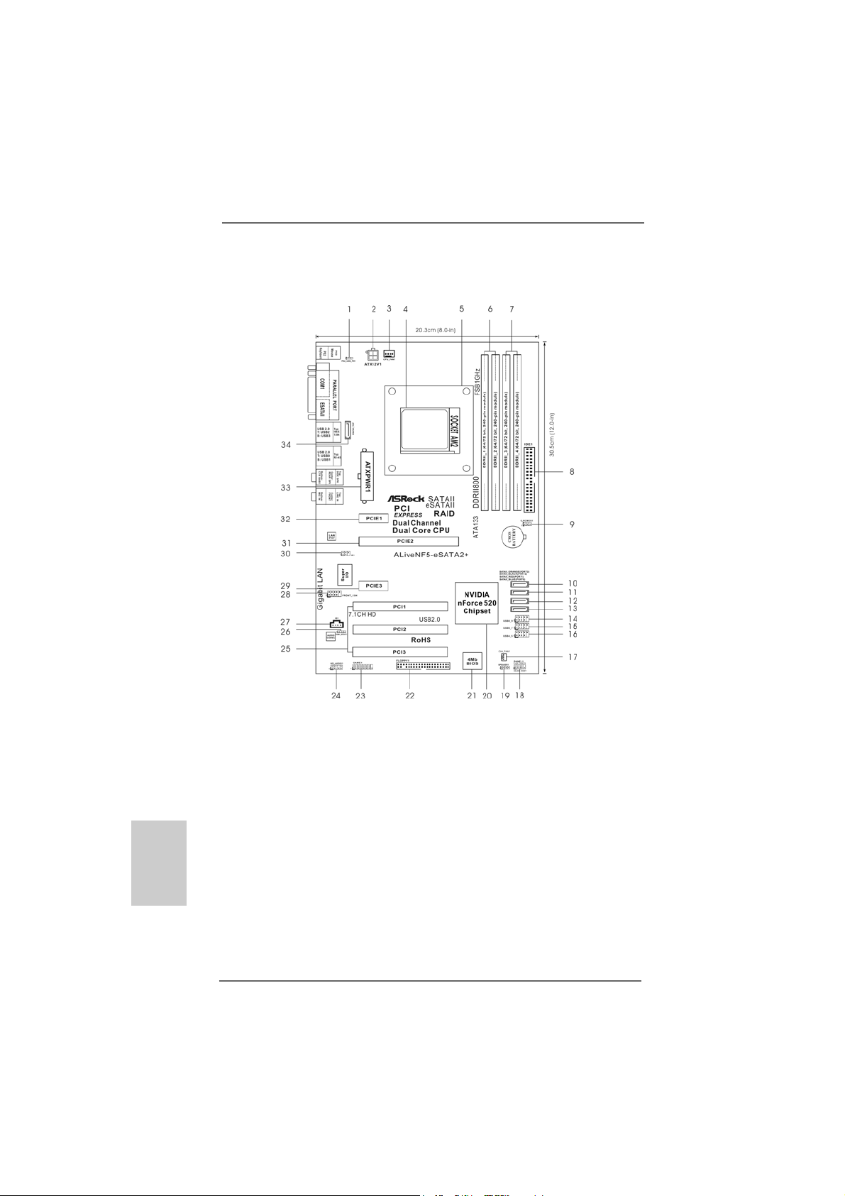
1 PS2_USB_PW1 Jumper 18 System Panel Header (PANEL1)
2 ATX 12V Power Connector (ATX12V1) 19 Chassis Speaker Header (SPEAKER 1)
3 CPU Fan Connector (CPU_FAN1) 20 NVIDIA nForce 520 Single Chip
4 AM2 940-Pin CPU Socket 21 Flash Memory
5 CPU Heatsink Retention Module 22 Floppy Connector (FLOPPY1)
6 2 x 240-pin DDRII DIMM Slots 23 Game Port Header (GAME1)
(Dual Channel A: DDRII_1, DDRII_2; Yellow) 24 Front Panel Audio Header (HD_AUDIO1)
7 2 x 240-pin DDRII DIMM Slots 25 PCI Slots (PCI1- 3)
(Dual Channel B: DDRII_3, DDRII_4; Orange) 26 HDMI_SPDIF Header (HDMI_SPDIF1)
8 Primary IDE Connector (IDE1, Blue) 27 Internal Audio Connector: CD1 (Black)
9 Clear CMOS Jumper (CLRCMOS1) 28 Front Panel IEEE 1394 Header
10 SATAII Connector (SATAII_ORANGE (PORT3)) (FRONT_1394)
11 SATAII Connector (SATAII_BLACK (PORT2)) 29 PCI Express x1 Slot (PCIE3)
12 SATAII Connector (SATAII_RED (PORT1)) 30 DeskExpress Hot Plug Detection Header
13 SATAII Connector (SAT AII_BLUE (PORT0)) (IR1)
14 USB 2.0 Header (USB8_9, Blue) 31 PCI Express x16 Slot (PCIE2)
15 USB 2.0 Header (USB6_7, Blue) 3 2 PCI Express x1 Slot (PCIE1)
16 USB 2.0 Header (USB4_5, Blue) 33 ATX Power Connector (ATXPWR1)
17 Chassis Fan Connector (CHA_FAN1) 34 eSATAII Connector (eSATAII_TOP)
ASRock ALiveNF5-eSATA2+ Motherboard
Page 3
ASRASR
ock 1394_eSock 1394_eS
ASR
ock 1394_eS
ASRASR
ock 1394_eSock 1394_eS
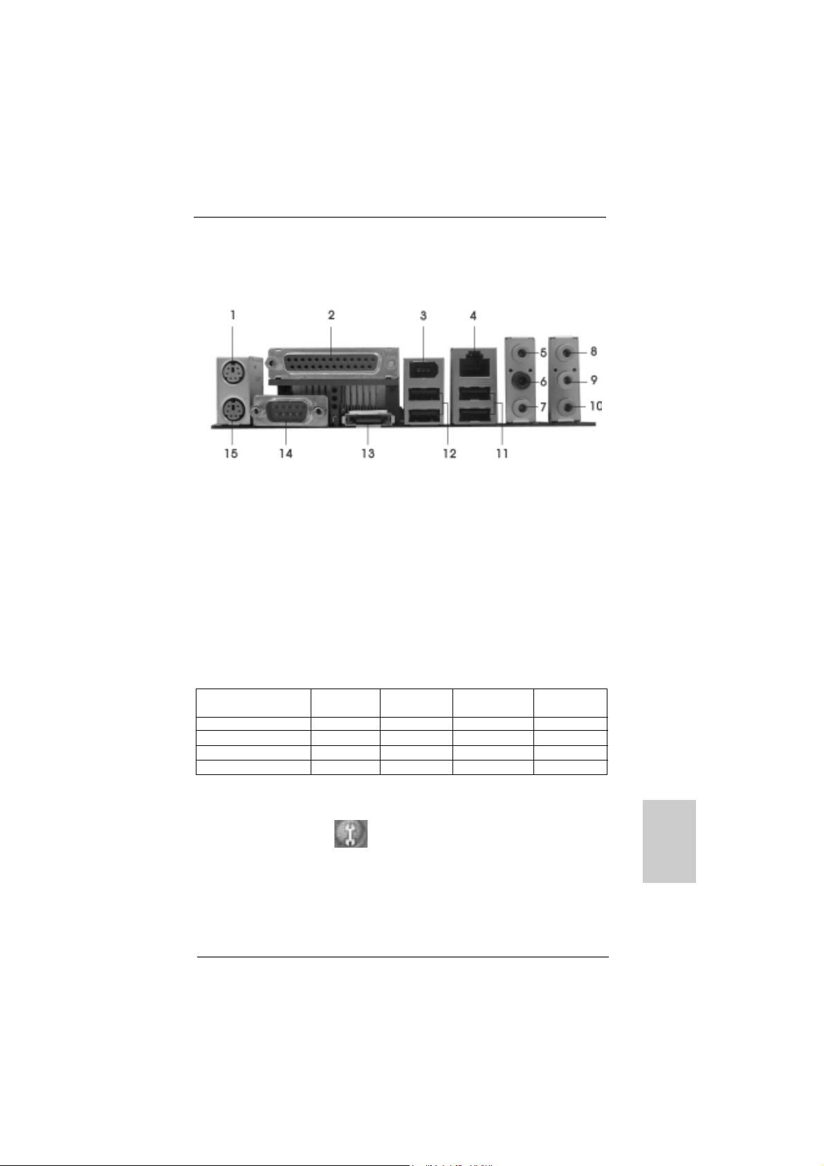
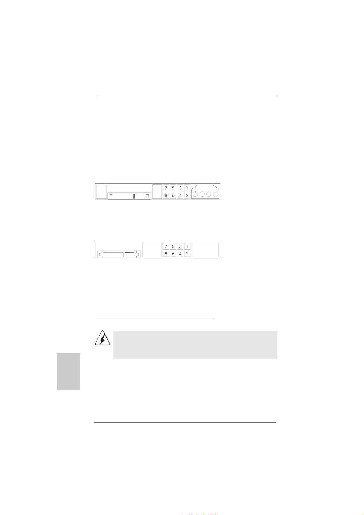
1 PS/2 Mouse Port (Green) * 9 Front Speaker (Lime)
2 Parallel Port 10 Microphone (Pink)
3 IEEE 1394 Port 11 USB 2.0 Ports (USB23)
4 RJ-45 Port 12 USB 2.0 Ports (USB01)
5 Side Speaker (Gray) 13 eSATAII Port
6 Rear Speaker (Black) 14 COM Port
7 Central / Bass (Orange) 15 PS/2 Keyboard Port (Purple)
8 Line In (Light Blue)
* If you use 2-channel speaker, please connect the speaker’s plug into “Front Speaker Jack”.
See the table below for connection details in accordance with the type of speaker you use.
AA
TT
AII I/O PlusAII I/O Plus
A
T
AII I/O Plus
AA
TT
AII I/O PlusAII I/O Plus
TABLE for Audio Output Conne ction
Audio Output ChannelsFront Speaker Rear Speaker Central / Bass Side Speaker
(No. 9) (No. 6) (No. 7) (No. 5)
2 V -- -- -4VV---6VVV-8VVVV
* To enable Multi-Streaming function, you need to connect a front panel audio cable to the front
panel audio header. After restarting your computer, you will find “Mixer” tool on your system.
Please select “Mixer ToolBox” , click “Enable playback multi-streaming”, and click
“ok”. Choose “2CH”, “4CH”, “6CH”, or “8CH” and then you are allowed to select “Realtek HDA
Primary output” to use Rear Speaker, Central/Bass, and Front Speaker, or select “Realtek
HDA Audio 2nd output” to use front panel audio.
ASRock ALiveNF5-eSATA2+ Motherboard
EnglishEnglish
EnglishEnglish
English
33
3
33
Page 4
1.1.
IntroductionIntroduction
1.
Introduction
1.1.
IntroductionIntroduction
Thank you for purchasing ASRock ALiveNF5-eSATA2+ motherboard, a reliable
motherboard produced under ASRock’s consistently stringent quality control. It delivers excellent performance with robust design conforming to ASRock’s commitment to quality and endurance.
This Quick Installation Guide contains introduction of the motherboard and step-bystep installation guide. More detailed information of the motherboard can be found in
the user manual presented in the Support CD.
Because the motherboard specifications and the BIOS software might
be updated, the content of this manual will be subject to change without
notice. In case any modifications of this manual occur, the updated
version will be available on ASRock website without further notice. You
may find the latest VGA cards and CPU support lists on ASRock website
as well. ASRock website http://www.asrock.com
If you require technical support related to this motherboard, please visit
our website for specific information about the model you are using.
www.asrock.com/support/index.asp
1.11.1
PP
ackack
1.1
1.11.1
1 x ASRock ALiveNF5-eSATA2+ Motherboard
(ATX Form Factor: 12.0-in x 8.0-in, 30.5 cm x 20.3 cm)
1 x ASRock ALiveNF5-eSATA2+ Quick Installation Guide
1 x ASRock ALiveNF5-eSATA2+ Support CD
1 x Ultra A TA 66/100/133 IDE Ribbon Cable (80-conductor)
1 x 3.5-in Floppy Drive Ribbon Cable
2 x Serial ATA (SATA) Data Cables (Optional)
1 x Serial ATA (SATA) HDD Power Cable (Option al)
1 x HDMI_SPDIF Cable (Optional)
1 x “ASRock 1394_eSATAII I/O Plus” I/O Shield
age Contentsage Contents
P
ack
age Contents
PP
ackack
age Contentsage Contents
English
EnglishEnglish
EnglishEnglish
44
4
44
ASRock ALiveNF5-eSATA2+ Motherboard
Page 5
1.21.2
SpecificationsSpecifications
1.2
Specifications
1.21.2
SpecificationsSpecifications
Platform - ATX Form Factor: 12.0-in x 8.0-in, 30.5 cm x 20.3 cm
CPU - Socket AM2 for AMD AthlonTM 64FX / 64X2 / X2 / 64 and Sempron
processors
- AMD LIVE!TM Ready
- Supports AMD’s Cool ‘n’ QuietTM T echnology
- FSB 1000 MHz (2.0 GT/s)
- Supports Untied Overclocking Technology (see CAUTION 1)
- Supports Hyper-Tran sport Technology
Chipset - NVIDIA® nForce 520
Memory - Dual Channel DDRII Memory T echnology (see CAUTION 2)
- 4 x DDRII DIMM slots
- Support DDRII800/667/533
- Max. capacity: 8GB (see CAUTION 3)
Hybrid Booster - CPU Frequency Stepless Control (see CAUTION 4)
- ASRock U-COP (see CAUTION 5)
- Boot Failure Guard (B.F.G.)
- ASRock AM2 Boost: ASRock Patented Technology to boost
memory performance up to 12.5% (see CAUTION 6)
Expansion Slot - 1 x PCI Express x16 slot
- 2 x PCI Express x1 slots
- 3 x PCI slots
Audio - 7.1 CH Windows® VistaTM Premium Level HD Audio
(ALC888 Audio Codec)
LAN - PCIE x1 Gigabit LAN 10/100/1000 Mb/s
- Realtek RTL81 1 1B / RTL81 11C
- Supports Wa ke-On-LAN
Rear Panel I/O ASRock 1394_eSA T AII I/O Plus
- 1 x PS/2 Mouse Port
- 1 x PS/2 Keyboard Port
- 1 x Serial Port: COM1
- 1 x Parallel Port (ECP/EPP Support)
- 4 x Ready-to-Use USB 2.0 Ports
- 1 x eSATAII Port
- 1 x RJ-45 Port
- 1 x IEEE 1394 Port
- HD Audio Jack: Side Speaker/Re ar Spea ker/Central/Bass/
Line in/Front Speaker/Microphone (see CAUTION 7)
EnglishEnglish
EnglishEnglish
English
ASRock ALiveNF5-eSATA2+ Motherboard
55
5
55
Page 6
English
EnglishEnglish
EnglishEnglish
Connector - 4 x SATAII 3.0Gb/s connectors, support RAID (RAID 0, RAID 1,
RAID 0+1, RAID 5 a nd JBOD), NCQ, AHCI and “Hot Plug”
functions (see CAUTION 8)
- 1 x eSATAII 3.0Gb/s connector (shared with 1 SATAII
connector), supports NCQ, AHCI and “Hot Plug” functions
(see CAUTION 9)
- 1 x ATA133 IDE connector (supports 2 x IDE devices)
- 1 x Floppy connector
- 1 x DeskExpre ss Hot Plug Detection header
- 1 x Game header
- 1 x HDMI_SPDIF header
- 1 x IEEE 1394 header
- CPU/Chassis FAN connector
- 20 pin A TX power conne ctor
- 4 pin 12V power connector
- CD in header
- Front panel audio connector
- 3 x USB 2.0 headers (support 6 USB 2.0 ports)
(see CAUTION 10)
BIOS Feature - 4Mb AMI BIOS
- AMI Legal BIOS
- Supports “Plug and Play”
- ACPI 1.1 Compliance Wake Up Events
- Supports jumperfree
- SMBIOS 2.3.1 Support
Support CD - Drivers, Utilities, AntiVirus Software (Trial Version)
Hardware - CPU Internal T emperature Sensing
Monitor - CPU Ambient Temperature Sensing
- Chassis Temperature Sensing
- CPU Fan Tachometer
- Chassis Fa n Tachometer
- CPU Quiet Fan
- Voltage Monitoring: +12V, +5V, +3.3V, Vcore
OS - Microsoft® Windows® 2000 / XP / XP Media Center / XP 64-bit
/ VistaTM / VistaTM 64-bit compliant
Certifications - FCC, CE, WHQL Certificated
66
6
66
ASRock ALiveNF5-eSATA2+ Motherboard
Page 7

WARNING
Please realize that there is a certain risk involved with overclocking, including
adjusting the setting in the BIOS, applying Untied Overclocking Technology, or using
the third-party overclocking tools. Overclocking may affect your system stability, or
even cause damage to the components and devices of your system. It should be
done at your own risk and expense. We are not responsible for possible damage
caused by overclocking.
CAUTION!
1. This motherboard supports Untied Overclocking Technology. Please read
“Untied Overclocking Technology” on page 31 for details.
2. This motherboard supports Dual Channel Memory Technology. Before
you implement Dual Channel Memory Technology, make sure to read
the installation guide of memory modules on page 11 for proper
installation.
3. Due to the operating system limitation, the actual memory size may be
less than 4GB for the reservation for system usage under Windows® XP
and Windows® VistaTM. For Windows® XP 64-bit and Windows® Vista
64-bit with 64-bit CPU, there is no such limitation.
4. Although this motherboard offers stepless control, it is not recommended
to perform over-clocking. Frequencies other than the recommended CPU
bus frequencies may cause the instability of the system or damage the
CPU.
5. While CPU overheat is detected, the system will automatically shutdown.
Before you resume the system, please check if the CPU fan on the
motherboard functions properly and unplug the power cord, then plug it
back again. To improve heat dissipation, remember to spray thermal grease
between the CPU and the heatsink when you install the PC system.
6. This motherboard supports ASRock AM2 Boost overclocking technology. If
you enable this function in the BIOS setup, the memory performance will
improve up to 12.5%, but the effect still depends on the AM2 CPU you
adopt. Enabling this function will overclock the chipset/CPU reference clock.
However, we can not guarantee the system stability for all CPU/DRAM
configurations. If your system is unstable after AM2 Boost function is enabled,
it may not be applicative to your system. You may choose to disable this
function for keeping the stability of your system.
7. For microphone input, this motherboard supports both stereo and mono
modes. For audio output, this motherboard supports 2-channel, 4-channel,
6-channel, and 8-channel modes. Please check the table on page 3 for
proper connection.
8. Before installing SATAII hard disk to SATAII connector, please read the “SATAII
Hard Disk Setup Guide” on page 24 to adjust your SATAII hard disk drive to
SATAII mode. You can also connect SATA hard disk to SATAII connector
directly.
TM
EnglishEnglish
EnglishEnglish
English
ASRock ALiveNF5-eSATA2+ Motherboard
77
7
77
Page 8
9. This motherboard supports eSATAII interface, the external SATAII
specification. Please read “eSATAII Interface Introduction” on page 21
for details about eSATAII and eSATAII installation procedures.
10. Power Management for USB 2.0 works fine under Microsoft® Windows
VistaTM 64-bit / VistaTM / XP 64-bit / XP SP1 or SP2 / 2000 SP4.
1.31.3
Minimum Hardware RMinimum Hardware R
1.3
Minimum Hardware R
1.31.3
Minimum Hardware RMinimum Hardware R
TMTM
TM
TMTM
VistaVista
Vista
VistaVista
For system integrators and users who purchase this motherboard and
plan to submit Windows® VistaTM Premium 2007 and Basic logo, please follow
below table for minimum hardware requirement.
CPU Sempron 2800+
Memory 1GB system memory (Premium)
VGA DX9.0 with WDDM Driver
* After June 1, 2007, all Windows® VistaTM systems are required to meet above
minimum hardware requirements in order to qualify for Windows® VistaTM Premium
2007 logo.
Premium 2007 and Basic Logo Premium 2007 and Basic Logo
Premium 2007 and Basic Logo
Premium 2007 and Basic Logo Premium 2007 and Basic Logo
512MB system memory (Basic)
with 128bit VGA memory (Premium)
with 64bit VGA memory (Basic)
equirement Tequirement T
equirement T
equirement Tequirement T
able for Wable for W
able for W
able for Wable for W
®
indowsindows
indows
indowsindows
®®
®
®®
English
EnglishEnglish
EnglishEnglish
88
8
88
ASRock ALiveNF5-eSATA2+ Motherboard
Page 9

2.2.
InstallationInstallation
2.
Installation
2.2.
InstallationInstallation
This is an ATX form factor (12.0-in x 8.0-in, 30.5 cm x 20.3 cm) motherboard.
Before you install the motherboard, study the configuration of your chassis to ensure that the motherboard fits into it.
Pre-installation PrecautionsPre-installation Precautions
Pre-installation Precautions
Pre-installation PrecautionsPre-installation Precautions
Take note of the following precautions before you install motherboard
components or change any motherboard settings.
Before you install or remove any component, ensure that the
power is switched off or the power cord is detached from the
power supply. Failure to do so may cause severe damage to the
motherboard, peripherals, and/or components.
1. Unplug the power cord from the wall socket before touching any
component.
2. To avoid damaging the motherboard components due to static
electricity, NEVER place your motherboard directly on the carpet or
the like. Also remember to use a grounded wrist strap or touch a
safety grounded object before you handle components.
3. Hold components by the edges and do not touch the ICs.
4. Whenever you uninstall any component, place it on a grounded antistatic pad or in the bag that comes with the component.
5. When placing screws into the screw holes to secure the motherboard
to the chassis, please do not over-tighten the screws! Doing so may
damage the motherboard.
ASRock ALiveNF5-eSATA2+ Motherboard
EnglishEnglish
EnglishEnglish
English
99
9
99
Page 10
2.12.1
CPU InstallationCPU Installation
2.1
CPU Installation
2.12.1
CPU InstallationCPU Installation
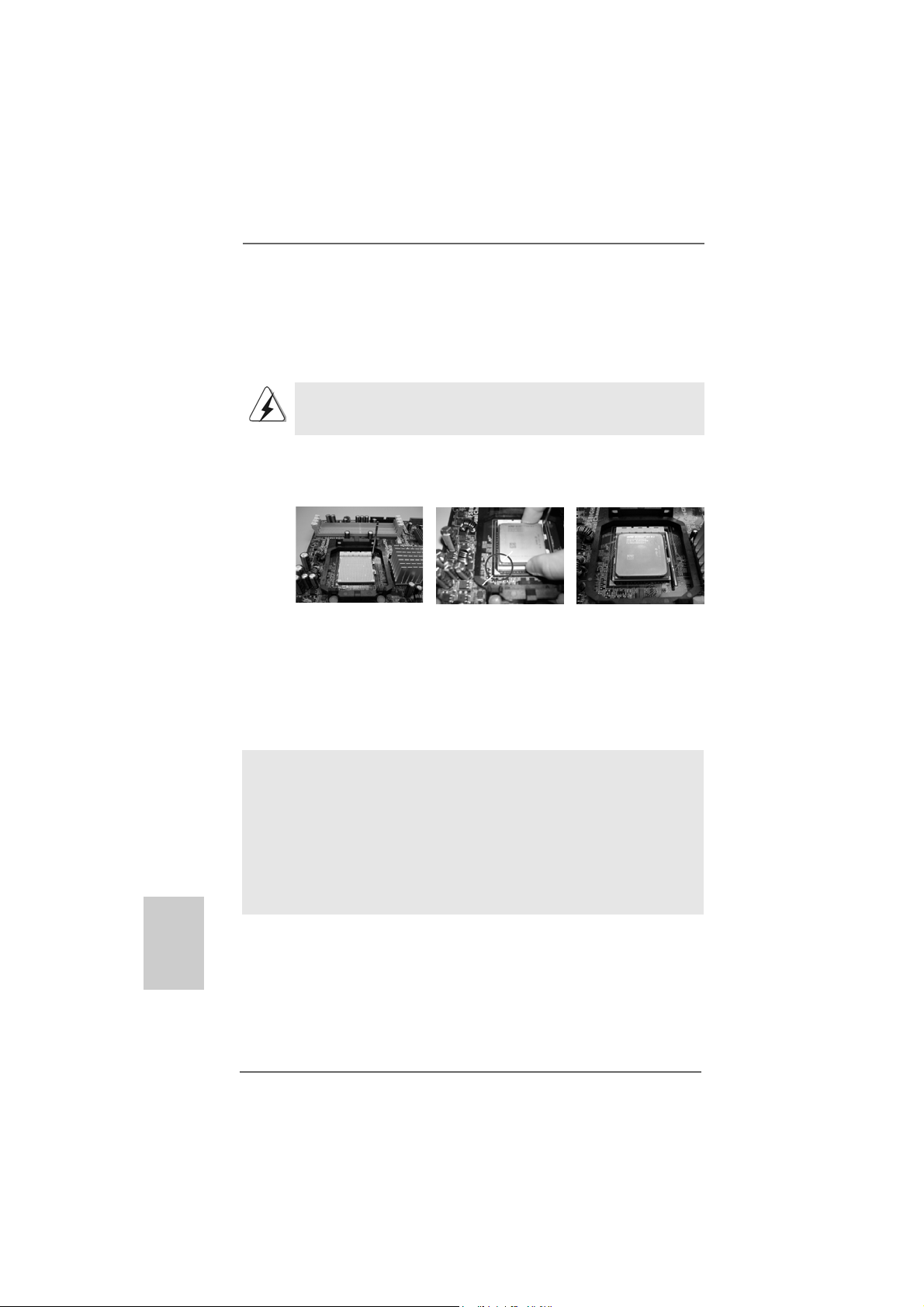
Step 1. Unlock the socket by lifting the lever up to a 90
o
angle.
Step 2. Position the CPU directly above the socket such that the CPU corner with
the golden triangle matches the socket corner with a small triangle.
Step 3. Carefully insert the CPU into the socket until it fits in place.
The CPU fits only in one correct orientation. DO NOT force the CPU
into the socket to avoid bending of the pins.
Step 4. When the CPU is in place, press it firmly on the socket while you push
down the socket lever to secure the CPU. The lever clicks on the side tab
to indicate that it is locked.
English
EnglishEnglish
EnglishEnglish
Lever 90° Up
STEP 1:
Lift Up The Socket Lever
2.22.2
Installation of CPU Fan and HeatsinkInstallation of CPU Fan and Heatsink
2.2
Installation of CPU Fan and Heatsink
2.22.2
Installation of CPU Fan and HeatsinkInstallation of CPU Fan and Heatsink
CPU Golden Triangle
Socket Corner Small Triangle
STEP 2 / STEP 3:
Match The CPU Golden Triangle
To The Socket Corner Small
Triangle
STEP 4:
Push Down And Lock
The Socket Lever
After you install the CPU into this motherboard, it is necessary to install a
larger heatsink and cooling fan to dissipate heat. You also need to spray
thermal grease between the CPU and the heatsink to improve heat
dissipation. Make sure that the CPU and the heatsink are securely fastened and in good contact with each other. Then connect the CPU fan to
the CPU FAN connector (CPU_FAN1, see Page 2, No. 3). For proper
installation, please kindly refer to the instruction manuals of the CPU fan
and the heatsink.
1010
10
1010
ASRock ALiveNF5-eSATA2+ Motherboard
Page 11
2.3 Installation of Memory Modules (DIMM)2.3 Installation of Memory Modules (DIMM)
2.3 Installation of Memory Modules (DIMM)
2.3 Installation of Memory Modules (DIMM)2.3 Installation of Memory Modules (DIMM)
This motherboard provides four 240-pin DD RII (Double Data Rate II) DIMM slots,
and supports Dual Channel Memory Technology. For dual channel configuration,
you always need to install identical (the same brand, speed, size and chiptype) DDRII DIMM pair in the slots of the same color. In other words, you have to
install identical DDRII DIMM pair in Dual Channel A (DDRII_1 and DDRII_2;
Yellow slots; see p.2 No.6) or identical DDRII DIMM pair in Dual Channel B
(DDRII_3 and DDRII_4; Ora nge slots; see p.2 No.7), so that Dual Channel Memory
Technology can be activated. This motherboard also allows you to install four
DDRII DIMMs for dual channel configuration, and please install identical DDRII
DIMMs in all four slots. You may refer to the Dual Channel Memory Configuration
Table below.
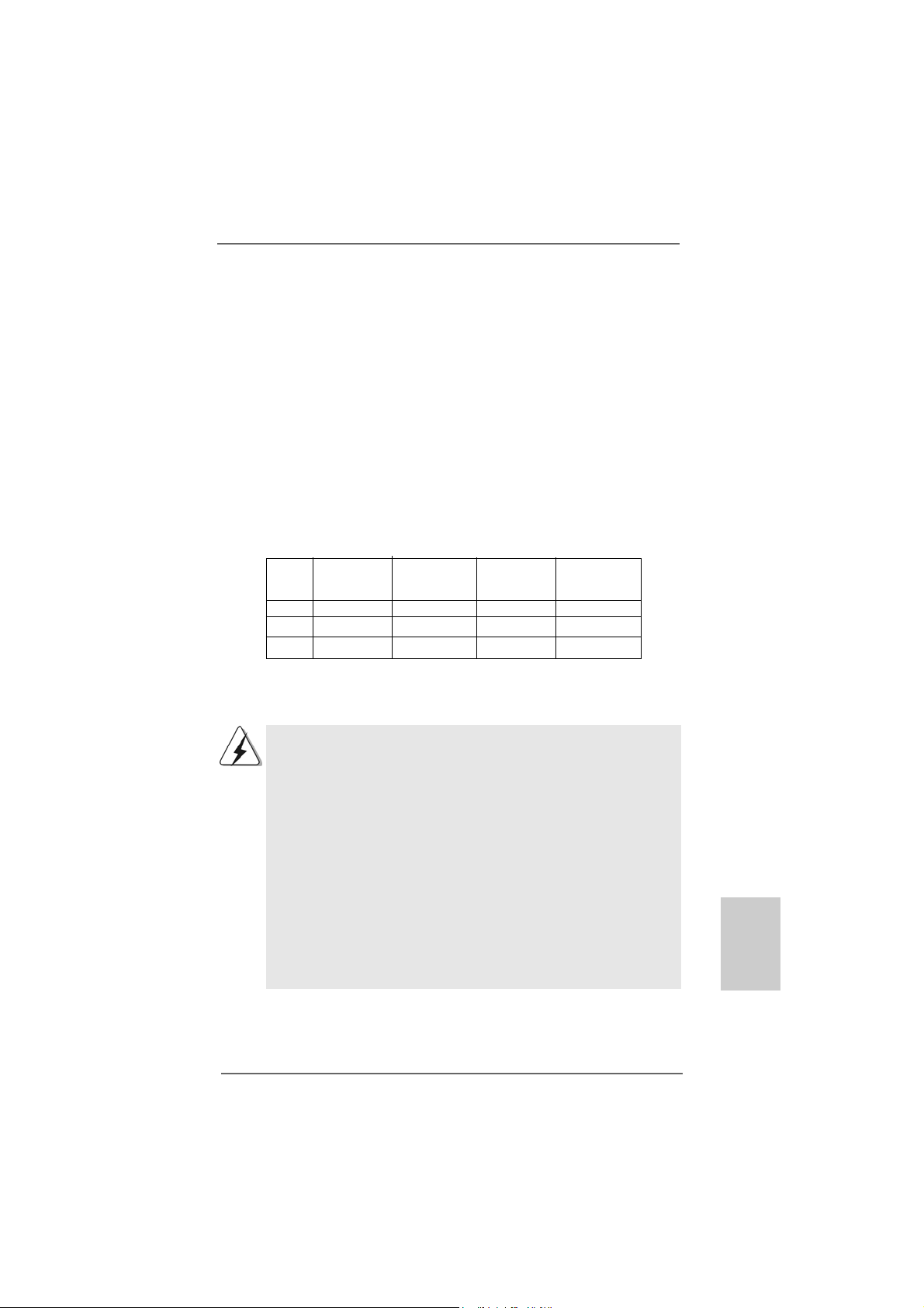
Dual Channel Memory Configurations
DDRII_1 DDRII_2 DDRII_3 DDRII_4
(Yellow Slot) (Yellow Slot) (Orange Slot) (Orange Slot)
(1) Populated Populated - (2) - - Populated Populated
(3)* Populated Populated Populated Populated
* For the configuration (3), please install identical DDRII DIMMs in all four slots.
1. If you want to install two memory modules, for optimal compatibility
and reliability, it is recommended to install them in the slots of the
same color. In other words, install them either in the set of yellow
slots (DDRII_1 and DDRII_2), or in the set of orange slots (DDRII_3
and DDRII_4).
2. If only one memory module or three memory modules are installed
in the DDRII DIMM slots on this motherboard, it is unable to activate
the Dual Channel Memory T e chnology.
3. If a pair of memory modules is NOT installed in the same Dual
Channel, for exa mple, in stalling a pair of memory module s in DD RII_1
and DDRII_3, it is unable to activate the Dual Channel Memory
Technology .
4. It is not allowed to install a DDR memory module into DDRII slot;
otherwise, this motherboard and DIMM may be damaged.
ASRock ALiveNF5-eSATA2+ Motherboard
1111
11
1111
EnglishEnglish
EnglishEnglish
English
Page 12
Installing a DIMMInstalling a DIMM
Installing a DIMM
Installing a DIMMInstalling a DIMM
Please make sure to disconnect power supply before adding or
removing DIMMs or the system components.
Step 1. Unlock a DIMM slot by pressing the retaining clips outward.
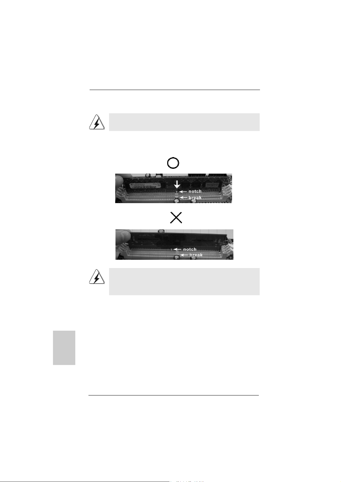
Step 2. Align a DIMM on the slot such that the notch on the DIMM matche s the brea k
on the slot.
English
EnglishEnglish
EnglishEnglish
1212
12
1212
The DIMM only fits in one correct orientation. It will cause permanent
damage to the motherboard and the DIMM if you force the DIMM into the
slot at incorrect orientation.
Step 3. Firmly insert the DIMM into the slot until the retaining clips at both ends fully
snap back in place and the DIMM is properly seated.
ASRock ALiveNF5-eSATA2+ Motherboard
Page 13
2.4 Expansion Slots (PCI and PCI Express Slots)2.4 Expansion Slots (PCI and PCI Express Slots)
2.4 Expansion Slots (PCI and PCI Express Slots)
2.4 Expansion Slots (PCI and PCI Express Slots)2.4 Expansion Slots (PCI and PCI Express Slots)
There are 3 PCI slots and 3 PCI Express slots on this motherboard.
PCI Slots: PCI slots are used to install expansion cards that have the 32-bit PCI
interface.
PCIE Slots: PCIE1 / PCIE3 (PCIE x1 slot) is used for PCI Express cards with x1
lane width cards, such as Gigabit LAN card, SAT A2 card, etc.
PCIE2 (PCIE x16 slot) is used for PCI Express cards with x16 lane
width graphics cards.
Installing an expansion cardInstalling an expansion card
Installing an expansion card
Installing an expansion cardInstalling an expansion card
Step 1. Bef ore in stalling the expansion card, please ma ke sure that the power
supply is switched off or the power cord is unplugged. Plea se re a d the
documentation of the expansion card a nd ma ke necessary hardware
settings for the card before you start the installation.
Step 2. Remove the system unit cover (if your motherboard is already installed in a
chassis).
Step 3. Re move the bracket facing the slot that you intend to use. Keep the screws
for later use.
Step 4. Align the card connector with the slot and press firmly until the card is
completely seated on the slot.
Step 5. Fasten the card to the chassis with screws.
Step 6. Replace the system cover.
ASRock ALiveNF5-eSATA2+ Motherboard
1313
13
1313
EnglishEnglish
EnglishEnglish
English
Page 14
2.52.5
Jumpers SetupJumpers Setup
2.5
Jumpers Setup
2.52.5
Jumpers SetupJumpers Setup
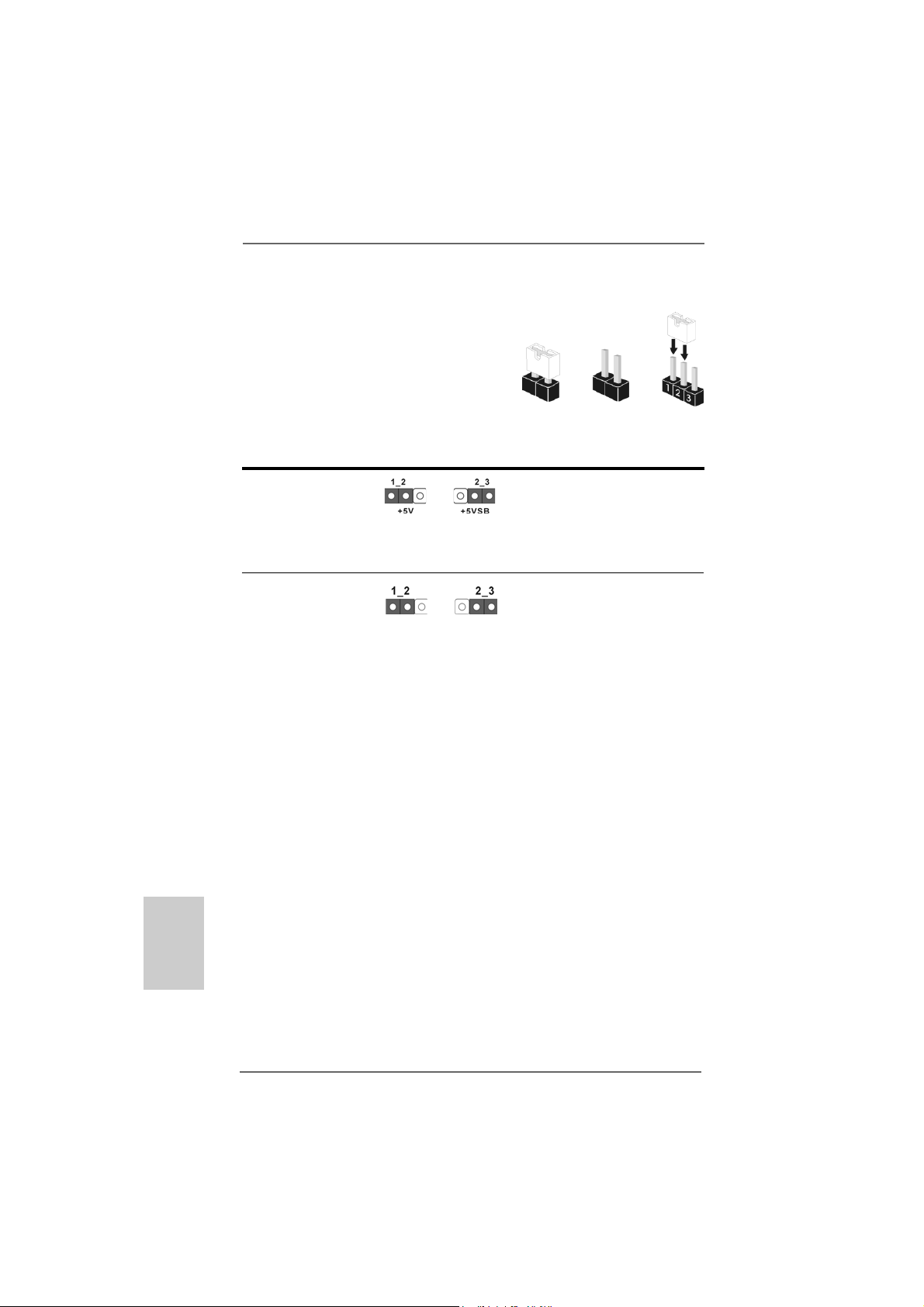
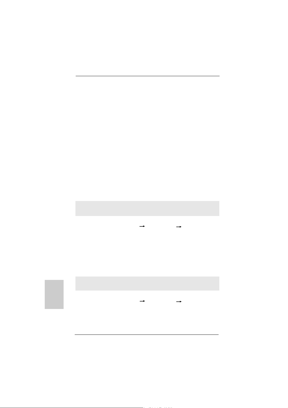
The illustration shows how jumpers are
setup. When the jumper cap is placed on
pins, the jumper is “Short”. If no jumper cap
is placed on pins, the jumper is “Open”. The
illustration shows a 3-pin jumper whose pin1
and pin2 are “Short” when jumper cap is
placed on these 2 pins.
Jumper Setting
PS2_USB_PW1 Short pin2, pin3 to enable
(see p.2, No. 1) +5VSB (standby) for PS/2 or
USB wake up events.
Note: To select +5VSB, it requires 2 Amp and higher standby current provided by
power supply.
Clear CMOS Jumper
(CLRCMOS1)
(see p.2, No. 9)
Note: CLRCMOS1 allows you to clear the data in CMOS. The data in CMOS includes
system setup information such as system password, date, time, and system
setup parameters. To clear and reset the system parameters to default setup,
please turn off the computer and unplug the power cord from the power
supply. After waiting for 15 seconds, use a jumper cap to short pin2 and pin3
on CLRCMOS1 for 5 seconds. However, please do not clear the CMOS right
after you update the BIOS. If you need to clear the CMOS when you just finish
updating the BIOS, you must boot up the system first, and then shut it down
before you do the clear-CMOS action.
Clear CMOSDefault
OpenShort
English
EnglishEnglish
EnglishEnglish
1414
14
1414
ASRock ALiveNF5-eSATA2+ Motherboard
Page 15
2.6 Onboard Headers and Connectors2.6 Onboard Headers and Connectors
2.6 Onboard Headers and Connectors
2.6 Onboard Headers and Connectors2.6 Onboard Headers and Connectors
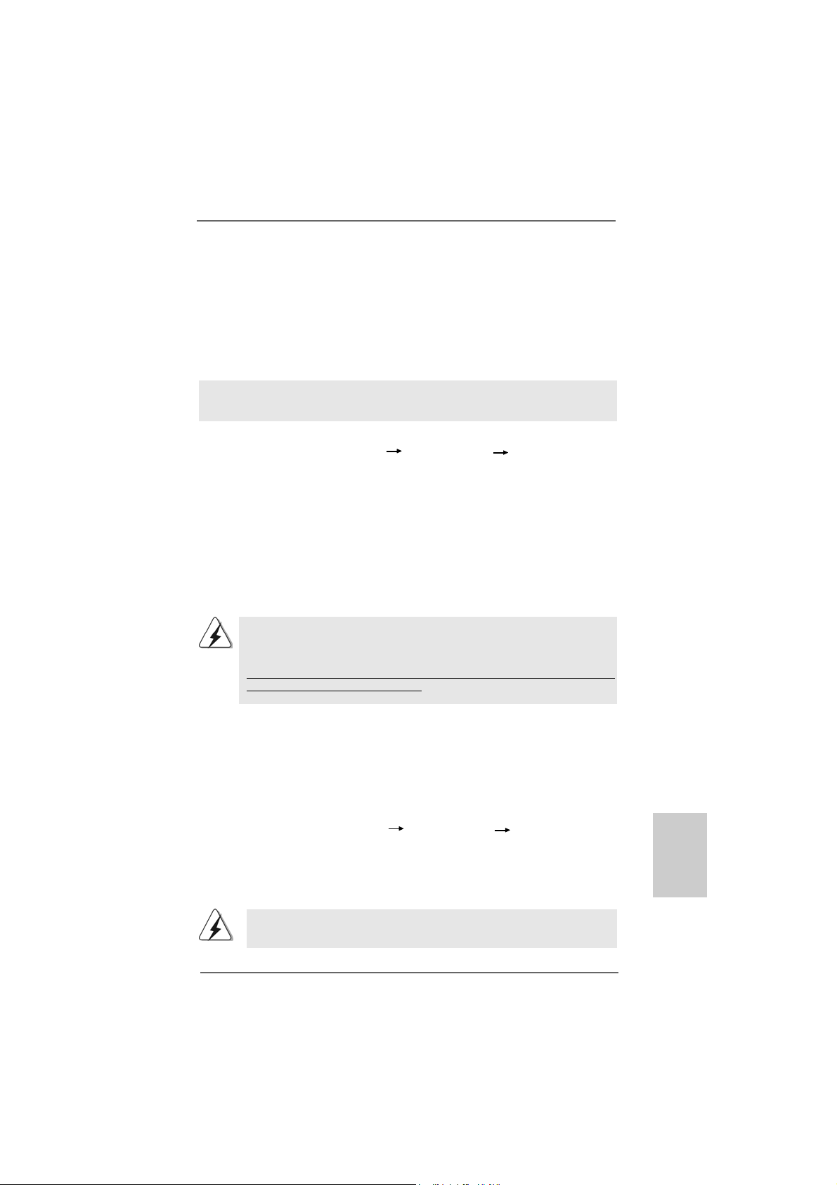
Onboard headers and connectors are NOT jumpers. Do NOT place
jumper caps over these headers and connectors. Placing jumper caps
over the headers and connectors will cause permanent damage of the
motherboard!
•
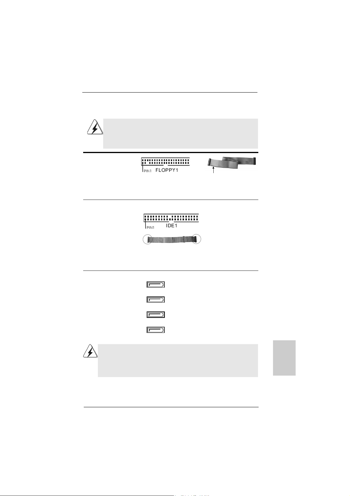
Floppy Connector
(33-pin FLOPPY1)
(see p.2, No. 22)
the red-striped side to Pin1
Note: Make sure the red-striped side of the cable is plugged into Pin1 side of the
connector.
Primary IDE connector (Blue)
(39-pin IDE1, see p.2, No. 8)
connect the blue end
to the motherboard
80-conductor ATA 66/100/133 cable
connect the black end
to the IDE devices
Note: Please refer to the instruction of your IDE device vendor for the details.
Serial ATA II Connectors These four Serial ATAII
(SAT AII_ORANGE (PORT3): (SATAII) connectors support
see p.2, No. 10) SATA data cables for internal
(SAT AII_BLACK (PORT2): storage devices. The current
see p.2, No. 1 1) SATAII interface allows up to
(SAT AII_RED (PORT1): 3.0 Gb/s data transfer rate.
see p.2, No. 12)
(SAT AII_BLUE (PORT0):
see p.2, No. 13)
SATAII_RED (PORT 1) connector can be used for internal storage
device or be connected to eSATAII connector to support eSATAII device.
Please read “eSATAII Interface Introduction” on page 21 for details
about eSATAII and eSATAII installation procedures.
SATAII_ORANGE (PORT3)
SATAII_BLACK (PORT2)
SATAII_RED (PORT1)
SATAII_BLUE (PORT0)
EnglishEnglish
EnglishEnglish
English
ASRock ALiveNF5-eSATA2+ Motherboard
1515
15
1515
Page 16
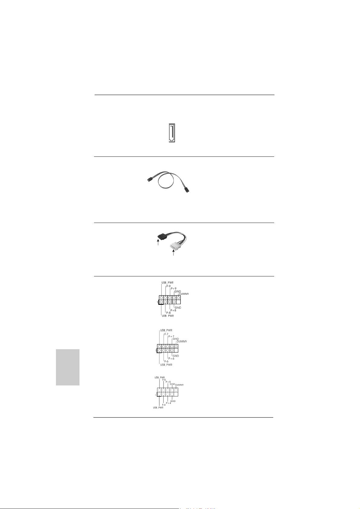
eSAT AII Connector This eSAT AII connector
(eSATAII_TOP: see p.2, No. 34) supports SA TA data cable f or
external SATAII function. The
current eSAT AII interfa ce
eSATAII_TOP
allows up to 3.0 Gb/s data
transfer rate.
Serial ATA (SA T A) Either end of the SAT A data cable
Data Cable can be connected to the SATA /
(Optional) SATAII hard disk or the SA T AII
connector on this motherboard.
Y ou can also use the SATA data
cable to connect SA T AII_RED
(PORT 1) connector and eSATAII
connector.
Serial ATA (SAT A) Please connect the black end of
Power Cable SAT A power ca ble to the power
(Optional) connector on each drive. Then
connect to the SAT A
HDD power connector
connect to the
power supply
connect the white end of SATA
power cable to the power
connector of the power supply.
USB 2.0 Headers Besides four default USB 2.0
(9-pin USB8_9) ports on the I/O panel, there are
(see p.2 No. 14) three USB 2.0 headers on this
motherboard. Each USB 2.0
header can support two USB
2.0 ports.
English
EnglishEnglish
EnglishEnglish
1616
16
1616
(9-pin USB6_7)
(see p.2 No. 15)
(9-pin USB4_5)
(see p.2 No. 16)
ASRock ALiveNF5-eSATA2+ Motherboard
Page 17
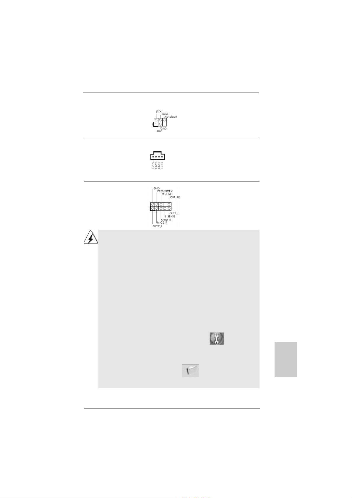
DeskExpress Hot Plug Dete ction This header supports the Hot
Header Plug detection function for
(5-pin IR1) ASRock DeskExpress.
(see p.2 No. 30)
Internal Audio Connectors This connector allows you
(4-pin CD1) to receive stereo audio input
(CD1: see p.2, No. 27) from sound sources such as
CD1
a CD-ROM, D VD-ROM, TV
tuner card, or MPEG card.
Front Panel Audio Header This is an interface for the front
(9-pin HD_AUDIO1) panel audio cable that allows
(see p.2, No. 24) convenient connection and
control of audio devices.
1. High Definition Audio supports Jack Sensing, but the panel wire on
the chassis must support HDA to function correctly. Please follow the
instruction in our manual and chassis manual to install your system.
2. If you use AC’97 audio panel, please install it to the front panel audio
header as below:
A. Connect Mic_IN (MIC) to MIC2_L.
B. Connect Audio_R (RIN) to OUT2_R and Audio_L (LIN) to OUT2_L.
C. Connect Ground (GND) to Ground (GND).
D. MIC_RET and OUT_RET are for HD audio panel only. You don’t
need to connect them for AC’97 audio panel.
E. Enter BIOS Setup Utility. Enter Advanced Settings, and then select
Chipset Configuration. Set the Front Panel Control option from
[Auto] to [Enabled].
F. Enter Windows system. Click the icon on the lower right hand
taskbar to enter Realtek HD Audio Manager.
For Windows
Click “Audio I/O”, select “Connector Settings” , choose
®
2000 / XP / XP 64-bit OS:
“Disable front panel jack detection”, and save the change by
clicking “OK”.
For Windows® VistaTM / VistaTM 64-bit OS:
Click the right-top “Folder” icon , choose “Disable front
panel jack detection”, and save the change by clicking “OK”.
ASRock ALiveNF5-eSATA2+ Motherboard
1717
17
1717
EnglishEnglish
EnglishEnglish
English
Page 18
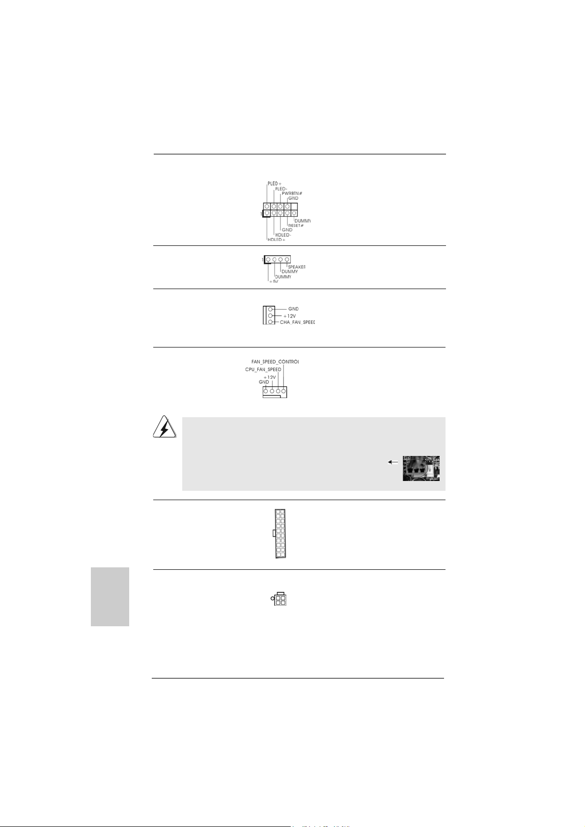
System Panel Header This header accommodates
(9-pin PANEL1) several system front panel
(see p.2, No. 18) functions.
Chassis Speaker Header Please connect the chassis
(4-pin SPEAKER 1) speaker to this header.
(see p.2, No. 19)
Chassis Fan Connector Please connect a chassis fan
(3-pin CHA_FAN1) cable to this connector and
(see p.2, No. 17) match the black wire to the
ground pin.
CPU Fan Connector Please connect the CPU fan
(4-pin CPU_FAN1) cable to this connector and
(see p.2, No. 3) match the black wire to the
ground pin.
1 2 3 4
Though this motherboard provides 4-Pin CPU fan (Quiet Fan) support, the 3-Pin
CPU fan still can work successfully even without the fan speed control function.
If you plan to connect the 3-Pin CPU fan to the CPU fan connector on this
motherboard, please connect it to Pin 1-3.
Pin 1-3 Connected
3-Pin Fan Installation
English
EnglishEnglish
EnglishEnglish
1818
18
1818
ATX Power Connector Please connect an ATX power
(20-pin ATXPW R1) supply to this connector.
(see p.2, No. 33)
ATX 12V Power Connector Please note that it is necessary
(4-pin A TX12V1) to connect a power supply with
(see p.2, No. 2) ATX 12V plug to this connector.
Failing to do so will cause power
up failure.
ASRock ALiveNF5-eSATA2+ Motherboard
Page 19
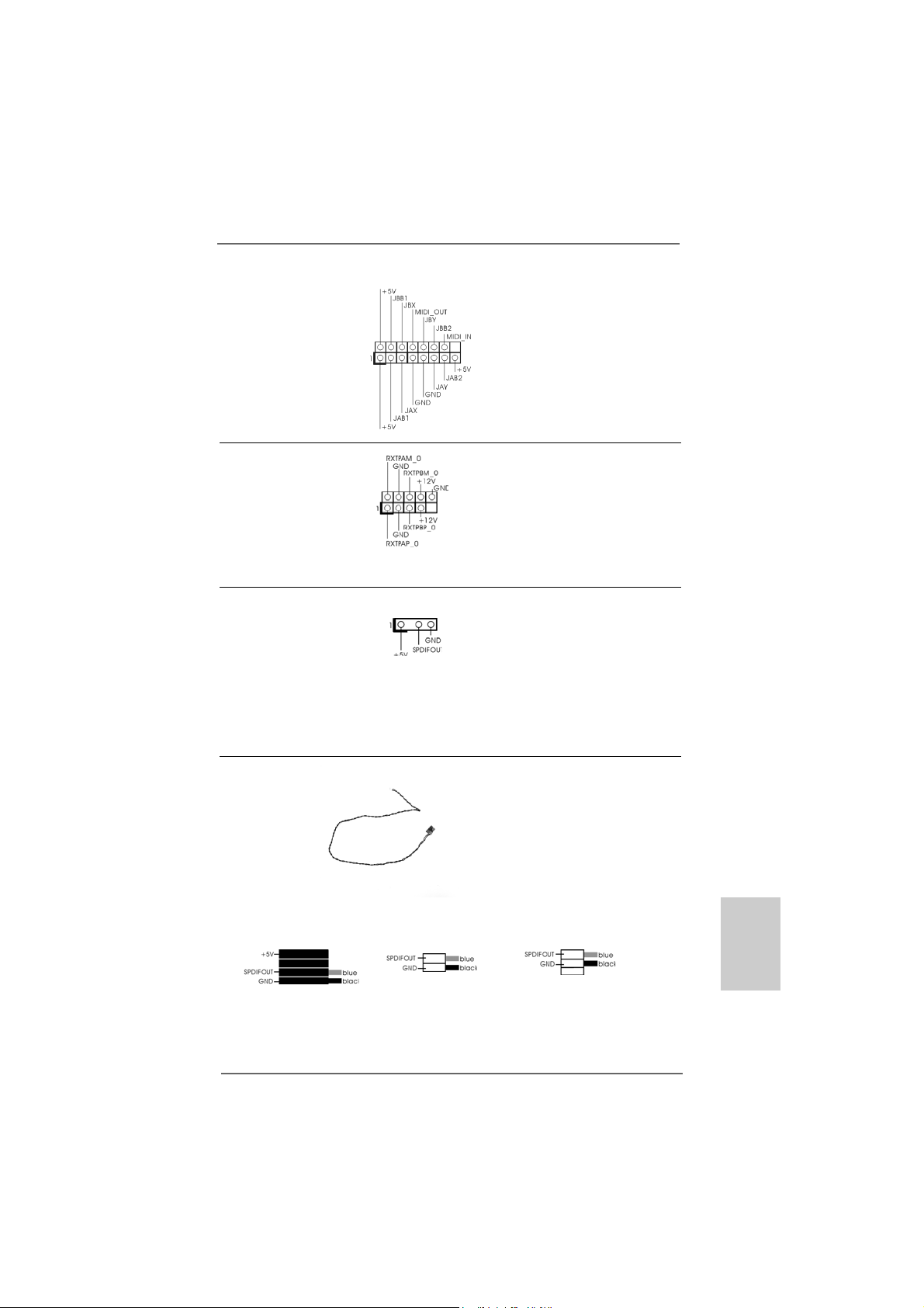
Game Port Hea der Connect a Game cable to this
(15-pin GAME1) header if the Game port bracket
(see p.2, No. 23) is installed.
IEEE 1394 Header Besides one default IEEE 1394
(9-pin FRONT_1394) port on the I/O panel, there is one
(see p.2 No. 28) IEEE 1394 header
(FRONT_1394) on this
motherboard. This IEEE 1394
header can support one IEEE
1394 port.
HDMI_SPDIF Header HDMI_SPDIF header, providing
(3-pin HDMI_SPDIF1) SPDIF audio output to HDMI V GA
(see p.2, No. 26) card, allows the system to
connect HDMI Digital TV/
projector/LCD devices. Please
connect the HDMI_SPDIF
connector of HDMI VGA card to
this header.
ion
HDMI_SPDIF Cable Please connect the black end (A)
(Optional) of HDMI_SPDIF cable to the
C
B
A
HDMI_SPDIF header on the
motherboard. Then connect the
white end (B or C) of
HDMI_SPDIF cable to the
HDMI_SPDIF connector of HDMI
VGA card.
A. black end B. white end (2-pin) C. white end (3-pin)
ASRock ALiveNF5-eSATA2+ Motherboard
1919
19
1919
EnglishEnglish
EnglishEnglish
English
Page 20
2.7 HDMI_SPDIF Header Connection Guide2.7 HDMI_SPDIF Header Connection Guide
2.7 HDMI_SPDIF Header Connection Guide
2.7 HDMI_SPDIF Header Connection Guide2.7 HDMI_SPDIF Header Connection Guide
HDMI (High-Definition Multi-media Interfa ce) is an all-digital audio/video specification,
which provides an interface between any compatible digital audio/video source,
such as a set-top box, DVD player, A/V receiver and a compatible digital audio or
video monitor, such as a digital television (DTV). A complete HDMI system requires a
HDMI VGA card and a HDMI ready motherboard with a HDMI_SPDIF header. This
motherboard is equipped with a HDMI_SPDIF header, which provides SPDIF audio
output to HDMI VGA card, allows the system to connect HDMI Digital TV/projector/
LCD devices. To use HDMI function on this motherboard, please carefully follow the
below steps.
•
Step 1. Install the HDMI VGA card to the PCI Express Graphics slot on this
motherboard. For the proper installation of HDMI VGA card, please refer
to the installation guide on page 13.
Step 2. Connect the black end (A) of HDMI_SPDIF cable to the
HDMI_SPDIF header (HDMI_SPDIF1, yellow, see page 2,
No. 26) on the motherboard.
Make sure to correctly connect the HDMI_SPDIF cable to the motherboard and the
HDMI VGA card according to the same pin definition. For the pin definition of
HDMI_SPDIF header and HDMI_SPDIF ca ble connectors, ple ase refer to page 19. For
the pin definition of HDMI_SPDIF connectors on HDMI VGA card, please refer to the
user manual of HDMI VGA card vendor. Incorrect connection may cause permanent
damage to this motherboard and the HDMI VGA card.
Step 3. Connect the white end (B or C) of HDMI_SPDIF cable to the HDMI_SPDIF
connector of HDMI VGA card. (There are two white ends (2-pin and 3-pin)
on HDMI_SPDIF cable. Please choose the appropriate white end a ccording
to the HDMI_SPDIF connector of the HDMI VGA card you install.
English
EnglishEnglish
EnglishEnglish
2020
20
2020
white end
(2-pin) (B)
Please do not connect the white end of HDMI_SPDIF cable to the wrong connector
of HDMI VGA card or other VGA card. Otherwise, the motherboard and the
VGA card may be damaged. For example, this picture shows the wrong
example of connecting HDMI_SPDIF cable to the fan connector of PCI
Express VGA card. Please refer to the VGA card user manual for
connector usage in advance.
white end
(3-pin) (C)
Step 4. Connect the HDMI output connector on HDMI VGA card to
HDMI device, such as HDTV. Please refer to the user manual
of HDTV and HDMI VGA card vendor for detailed connection
procedures.
Step 5. Install HDMI VGA card driver to your system.
ASRock ALiveNF5-eSATA2+ Motherboard
Page 21

2.8 eSA2.8 eSA
2.8 eSA
2.8 eSA2.8 eSA
What is eSATAII?
This motherboard supports eSATAII interface, the external SATAII specif ication.
eSATAII allows you to enjoy the SA TAII function provided by the I/O of your computer,
offering the high speed data trans fer rate up to 3.0Gb/s, a nd the convenient mobility
like USB. eSATAII is equipped with Hot Plug ca pa bility that en able s you to exchange
drives ea sily. For example, with eSATAII interfa ce, you may si mply plug your eSATAII
hard disk to the eSA TAII ports instead of opening your cha ssis to exchange your
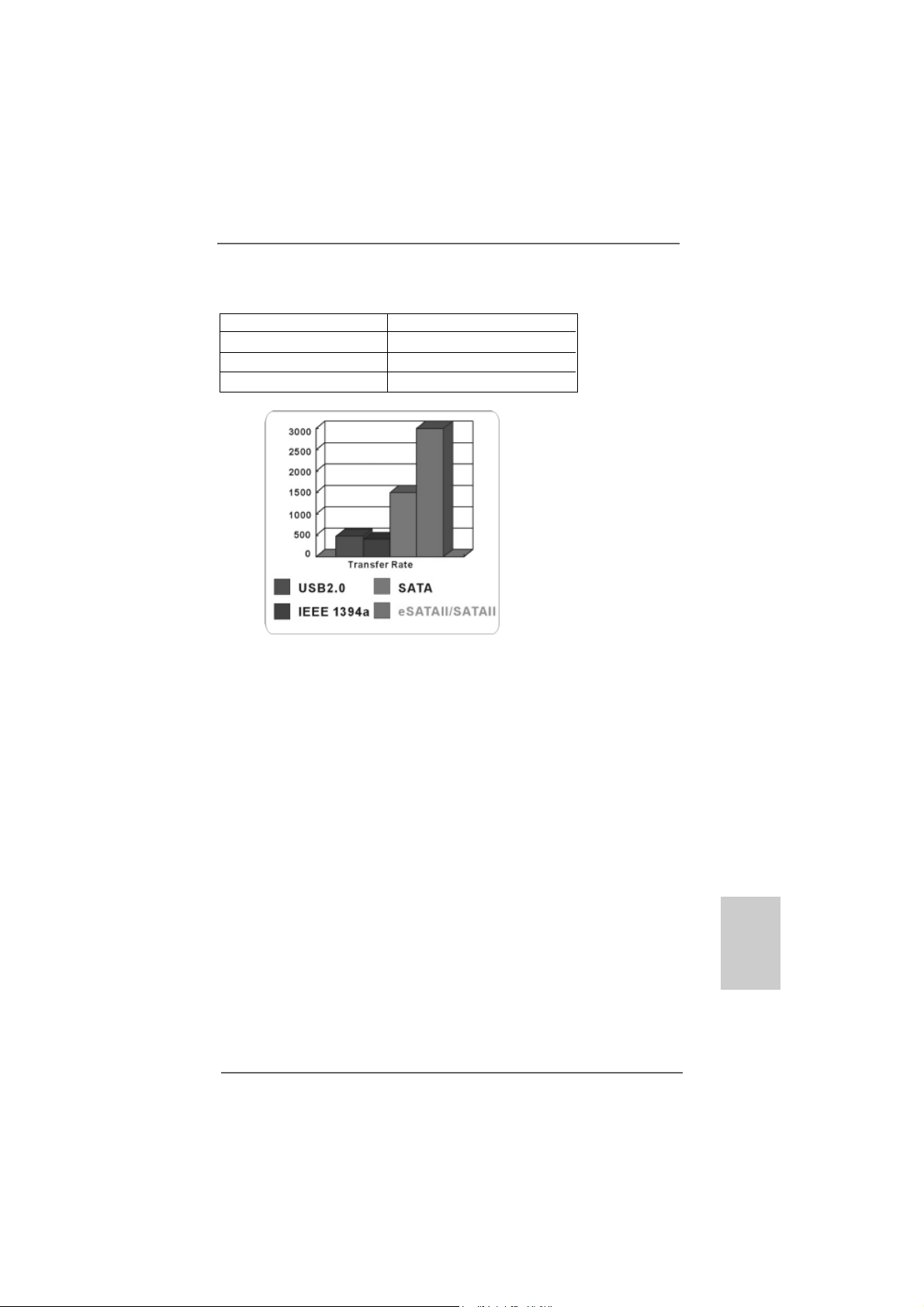
SATAII hard disk. Currently, on the market, the data transfer rate of USB 2.0 is up to
480Mb/s, and for IEEE 1394 is up to 400Mb/s. However, eSAT AII provide s the data
transfer rate up to 3000Mb/s, which is much higher tha n USB 2.0 and IEEE 1394, and
still keeps the convenience of Hot Plug feature. Therefore, on the basis of the
advantageous tra ns fer speed a nd the fa cilitating mobile capability, in the near future,
eSATAII will replace USB 2.0 a nd IEEE 1394 to be a trend f or external interface.
TT
AII InterAII Inter
T
AII Inter
TT
AII InterAII Inter
NOTE:
1. If you set “SATA Operation Mode” option in BIOS setup to AHCI or RAID mode, Hot
Plug function is supported with eSATAII devices. Therefore, you can insert or remove
your eSATAII devices to the eSATAII ports while the system is power-on and in
working condition.
2. If you set “SATA Operation Mode” option in BIOS setup to non-RAID mode, Hot Plug
function is not supported with eSATAII devices. If you still want to use eSATAII
function in non-RAID mode, please insert or remove your eSATAII devices to the
eSATAII ports only when the system is power-off.
3. Please refer to page 27 to 31 for detailed information of RAID mode, non-RAID
mode and AHCI mode.
face Introductionface Introduction
face Introduction
face Introductionface Introduction
ASRock ALiveNF5-eSATA2+ Motherboard
2121
21
2121
EnglishEnglish
EnglishEnglish
English
Page 22
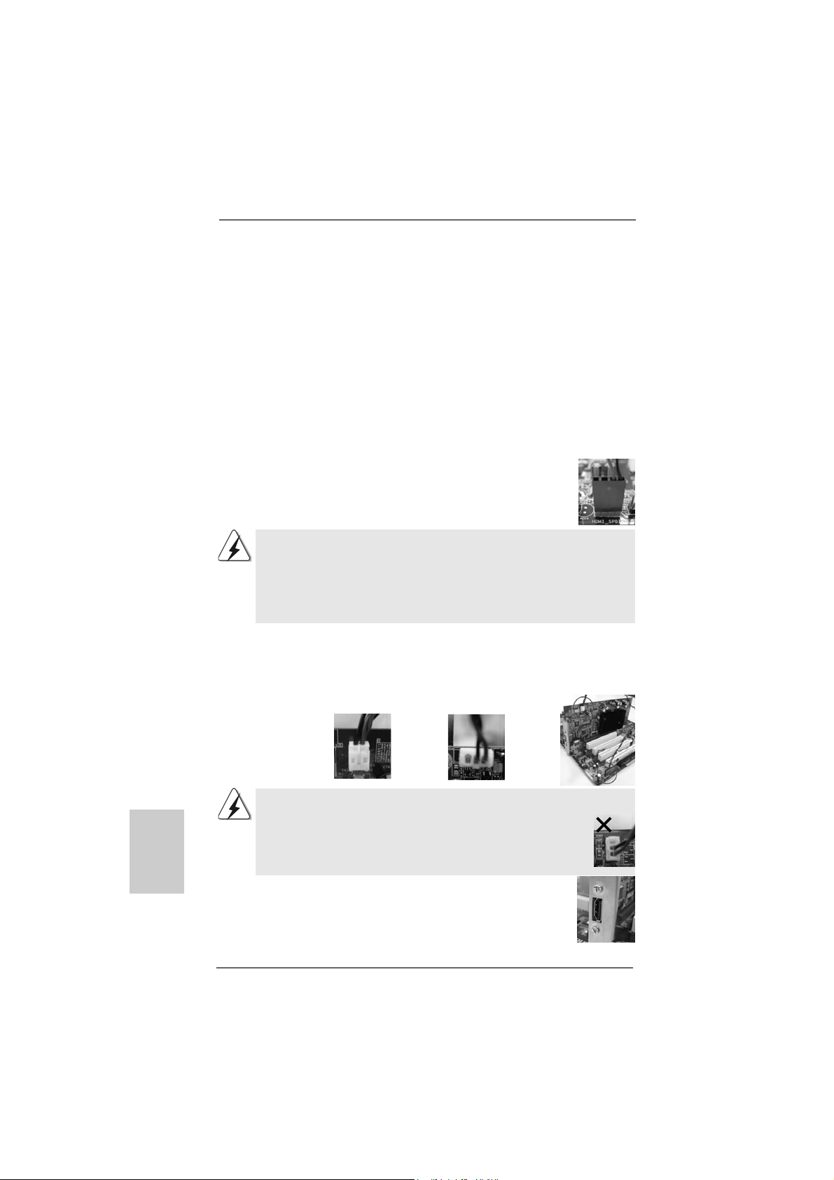
How to install eSATAII?
SATAII_RED (PORT 1)
eSATAII_TOP
1. In order to enable the eSATAII port of the I/O shield, you need to connect the red
SATAII connector (SA T AII_RED (POR T 1); see p.2 No.12) a nd the eSA TAII
connector (eSA TAII_TOP; see p.2 No.34) with a SATA data ca ble f irst.
Connect the SATA data
cable to the red SATAII
connector
(SATAII_RED (PORT 1))
Connect the SATA
data cable to the
eSATAII connector
(eSATAII_TOP)
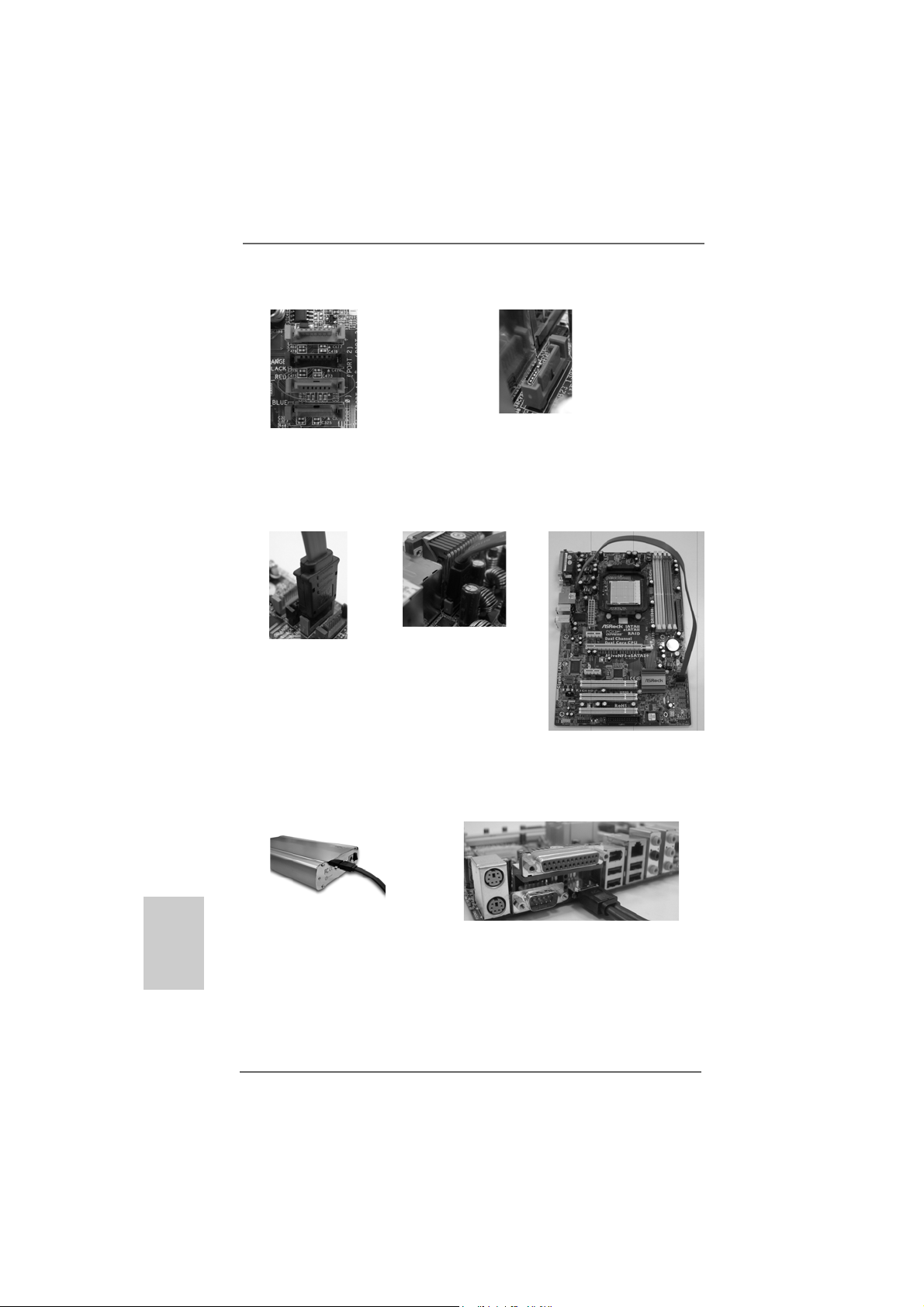
2. Use the eSAT AII device cable to connect eSATAII device a nd the eSATAII port of
the I/O shield according to the eSATAII connector that you connect the SATA
data cable.
English
EnglishEnglish
EnglishEnglish
2222
22
2222
Connect one end of the eSATAII
device cable to eSATAII device
ASRock ALiveNF5-eSATA2+ Motherboard
Connect the other end of the eSATAII
device cable to eSATAII port of the I/O
shield
Page 23
I_TOP
Comparison between eSATAII and other devices
IEEE 1394 400Mb/s
USB 2.0 480Mb/s
SATA 1.5Gb/s (1500Mb/s)
eSATAII/SATAII 3.0Gb/s (3000Mb/s)
ASRock ALiveNF5-eSATA2+ Motherboard
2323
23
2323
EnglishEnglish
EnglishEnglish
English
Page 24
2.92.9
SASA
TT
2.9
2.92.9
Before installing SA TAII hard disk to your computer, please carefully read below SATAII
hard disk setup guide. Some default setting of SA TAII hard disks may not be at SA TAII
mode, which operate with the best performance. In order to enable SATAII function,
please f ollow the below instruction with dif ferent vendors to correctly a djust your SATAII
hard disk to SA T AII mode in adva nce; otherwise, your SA TAII hard disk may fail to run at
SAT AII mode.
Western Digital
If pin 5 and pin 6 are shorted, SATA 1.5Gb/s will be enabled.
On the other hand, if you want to enable SATAII 3.0Gb/s, please remove the jumpers
from pin 5 and pin 6.
SAMSUNG
If pin 3 and pin 4 are shorted, SATA 1.5Gb/s will be enabled.
On the other hand, if you want to enable SATAII 3.0Gb/s, please remove the jumpers
from pin 3 and pin 4.
AII Hard Disk Setup GuideAII Hard Disk Setup Guide
SA
T
AII Hard Disk Setup Guide
SASA
TT
AII Hard Disk Setup GuideAII Hard Disk Setup Guide
English
EnglishEnglish
EnglishEnglish
2424
24
2424
HITACHI
Please use the Feature Tool, a DOS-bootable tool, for changing various ATA features.
Please visit HITACHI’s website for details:
http://www.hitachigst.com/hdd/support/download.htm
The above examples are just for your reference. For different SATAII hard
disk products of different vendors, the jumper pin setting methods may not
be the same. Please visit the vendors’ website for the updates.
ASRock ALiveNF5-eSATA2+ Motherboard
Page 25
2.102.10
Serial ASerial A
2.10
Serial A
2.102.10
Serial ASerial A
InstallationInstallation
Installation
InstallationInstallation
This motherboard adopts NVIDIA® nForce 520 chipset that supports Serial ATA (SATA)
/ Serial ATAII (SATAII) hard disk s and RAID functions. You may install SATA / SATAII
hard disks on this motherboard for internal storage devices. This section will guide
you to install the SATA / SATAII hard disks.
STEP 1: Install the SATA / SATAII hard disks into the drive bays of your chassis.
STEP 2: Connect the SATA power cable to the SATA / SATAII hard disk.
STEP 3: Connect one end of the SATA data cable to the motherboard’s SATAII
connector.
STEP 4: Connect the other end of the SATA data cable to the SATA / SAT AII hard
disk.
TT
A (SAA (SA
TT
A (SA
A (SAA (SA
A) / Serial AA) / Serial A
T
A) / Serial A
TT
A) / Serial AA) / Serial A
T
TT
1. If you plan to use RAID 0, RAID 1 or JBOD function, you need to install at
least 2 SATA / SATAII hard disks. If you plan to use RAID 5 function, you
need to install 3 SATA / SATAII hard disks. If you plan to use RAID 0+1
function, you need to install 4 SATA / SATAII hard disks.
2. It is recommended to build RAID on internal SATAII ports. In other
words, if SATAII_RED (PORT 1) is used for eSATAII port, please build
RAID on other SATAII ports. If eSATAII port is enabled, the internal SATAII
ports can only support RAID 0, RAID 1, JBOD or RAID 5.
TT
AII (SAAII (SA
T
AII (SA
TT
AII (SAAII (SA
TT
AII) Hard DisksAII) Hard Disks
T
AII) Hard Disks
TT
AII) Hard DisksAII) Hard Disks
ASRock ALiveNF5-eSATA2+ Motherboard
2525
25
2525
EnglishEnglish
EnglishEnglish
English
Page 26
2.11 Hot Plug and Hot Swap F2.11 Hot Plug and Hot Swap F
2.11 Hot Plug and Hot Swap F
2.11 Hot Plug and Hot Swap F2.11 Hot Plug and Hot Swap F
HDDs and eSA HDDs and eSA
HDDs and eSA
HDDs and eSA HDDs and eSA
This motherboard supports Hot Plug and Hot Swa p functions f or SA T A / SA T AII / eSA TAII
Devices in RAID / AHCI mode. NVIDIA® nForce 520 chipset provides hardware support
for Advanced Host controller Interfa ce (AHCI), a new programming interfa ce for SA T A host
controllers developed thru a joint industry effort. AHCI also provides usability enhancements
such as Hot Plug.
NOTE
What is Hot Plug Function?
If the SATA / SATAII HDDs are NOT set for RAID configuration, it is called
“Hot Plug” for the action to insert and remove the SATA / SATAII HDDs
while the system is still power-on and in working condition.
However, please note that it cannot perform Hot Plug if the OS has been
installed into the SATA / SATAII HDD.
What is Hot Swap Function?
If SATA / SATAII HDDs are built as RAID1 or RAID 5 then it is called “Hot
Swap” for the action to insert and remove the SATA / SATAII HDDs while
the system is still power-on and in working condition.
eSATAII is equipped with Hot Plug capability that enables you to exchange
drives easily. For example, with eSATAII interface, you may simply plug your
eSATAII devices to the eSATAII ports instead of opening your chassis to
exchange your SATAII hard disk.
TT
AII DevicesAII Devices
T
AII Devices
TT
AII DevicesAII Devices
unctions for SAunctions for SA
unctions for SA
unctions for SAunctions for SA
TT
A / SAA / SA
T
A / SA
TT
A / SAA / SA
TT
T
TT
AIIAII
AII
AIIAII
English
EnglishEnglish
EnglishEnglish
2626
26
2626
ASRock ALiveNF5-eSATA2+ Motherboard
Page 27
2.122.12
Driver Installation GuideDriver Installation Guide
2.12
Driver Installation Guide
2.122.12
Driver Installation GuideDriver Installation Guide
To install the drivers to your system, please insert the support CD to your optical drive
first. Then, the drivers compatible to your system ca n be auto-detected and listed on
the support CD driver page. Please follow the order from up to bottom side to install
those required drivers. Therefore, the drivers you install ca n work properly .
2.132.13
Installing WindowsInstalling Windows
2.13
Installing Windows
2.132.13
Installing WindowsInstalling Windows
TMTM
TM
/ Vista/ Vista
/ Vista
/ Vista/ Vista
If you want to install Windows® 2000, Windows® XP, Windows® XP 64-bit, Windows
VistaTM or Windows® VistaTM 64-bit on your SATA / SA TAII HDDs without RAID functions,
please f ollow below procedures according to the OS you install.
2.13.1 Installing Windows2.13.1 Installing Windows
2.13.1 Installing Windows
2.13.1 Installing Windows2.13.1 Installing Windows
RAID F RAID F
RAID F
RAID F RAID F
If you want to install Windows® 2000 / Windows® XP / Windows® XP 64-bit on your SA T A
/ SATAII HDDs without RAID functions, please follow below steps.
Using SATA / SA TAII HDDs and eSA TAII devices with NCQ and Hot Plug function s
STEP 1: Set Up BIOS.
A. Enter BIOS SETUP UTILITY Advanced screen IDE Configuration.
B. Set the “SAT A Operation Mode” option to [AHCI].
STEP 2: Make a SATA / SATAII driver diskette.
A. Insert the ASRock Support CD into your optical drive to boot your system.
B. During POST at the beginning of system boot-up, press <F11> key, and
C. When you see the message on the screen, “Generate Serial ATA driver
D. Then you will see these messages,
TMTM
64-bit W 64-bit W
64-bit W
64-bit W 64-bit W
Before installing Windows® 2000 to your system, your Windows® 2000 optical
disk is supposed to include SP4. If there is no SP4 included in your disk, please
visit the below website for proper procedures of making a SP4 disk:
http://www.microsoft.com/Windows2000/downloads/servicepacks/sp4/spdeploy.
htm#the_integrated_installation_fmay
unctionsunctions
unctions
unctionsunctions
then a window for boot devices selection appears. Please select CD-ROM
as the boot device.
diskette [YN]?”, press <Y>.
Plea se choose:
1. Generate AHCI Driver diskette for Windows2000/XP/XP64
2. Generate RAID Driver diskette for Windows2000/XP
3. Generate RAID Driver diskette for WindowsXP64
4. Exit
ASRock ALiveNF5-eSATA2+ Motherboard
®
2000 / XP / XP 64-bit / Vista 2000 / XP / XP 64-bit / Vista
2000 / XP / XP 64-bit / Vista
2000 / XP / XP 64-bit / Vista 2000 / XP / XP 64-bit / Vista
ithout RAID Fithout RAID F
ithout RAID F
ithout RAID Fithout RAID F
®
2000 / XP / XP 64-bit Without 2000 / XP / XP 64-bit Without
2000 / XP / XP 64-bit Without
2000 / XP / XP 64-bit Without 2000 / XP / XP 64-bit Without
unctionsunctions
unctions
unctionsunctions
TMTM
TM
TMTM
®
EnglishEnglish
EnglishEnglish
English
2727
27
2727
Page 28
Reboot system now
Press any key to continue
Plea se insert a floppy dis kette into the floppy drive. Select your required
item on the list according to the mode you choose and the OS you install.
Then press any key.
E. The system will start to format the floppy diskette and copy SATA / SATAII
drivers into the floppy diskette.
STEP 3: Install Windows® 2000 / XP / XP 64-bit OS on your system.
After making a SA T A / SATAII driver diskette, you can start to install Windows® 2000 / XP
/ XP 64-bit on your system. At the beginning of Windows® setup, press F6 to install a
third-party AHCI driver . When prompted, in sert the SA T A / SA T AII driver diskette containing the NVIDIA® AHCI driver . After reading the floppy disk, the drivers will be presented.
Select the driver to install according to the OS you install. The
drivers are as below:
A. NVIDIA nForce Storage Controller (required) Windows XP/2000
B. NVIDIA nForce Storage Controller (required) Windows XP64
Please select A f or Windows® 2000 / XP in AHCI mode. Ple ase select B for Windows
XP 64-bit in AHCI mode.
Using SATA / SATAII HDDs and eSATAII devices without NCQ and Hot Plug
functions
STEP 1: Set Up BIOS.
A. Enter BIOS SETUP UTILITY Advanced screen IDE Configuration.
B. Set the “SAT A Operation Mode” option to [non-RAID].
STEP 2: Install Windows® 2000 / XP / XP 64-bit OS on your system.
®
English
EnglishEnglish
EnglishEnglish
2828
28
2828
Vista Vista
Vista
Vista Vista
TMTM
TM
TMTM
/ Vista / Vista
/ Vista
/ Vista / Vista
2.13.2 Installing Windows2.13.2 Installing Windows
2.13.2 Installing Windows
2.13.2 Installing Windows2.13.2 Installing Windows
RAID F RAID F
RAID F
RAID F RAID F
If you want to install Windows® VistaTM / Windows® VistaTM 64-bit on your SATA / SATAII
HDDs without RAID functions, please follow below steps.
Using SATA / SA TAII HDDs and eSA TAII devices with NCQ a nd Hot Plug functions
STEP 1: Set Up BIOS.
A. Enter BIOS SETUP UTILITY Advanced screen IDE Configuration.
B. Set the “SAT A Operation Mode” option to [AHCI].
STEP 2: Install Windows® VistaTM / VistaTM 64-bit OS on your system.
Insert the Windows® VistaTM / Windows® VistaTM 64-bit optical disk into the optical drive
to boot your system, and follow the instruction to install Windows® VistaTM / Windows
VistaTM 64-bit OS on your system. When you see “Where do you want to
unctionsunctions
unctions
unctionsunctions
ASRock ALiveNF5-eSATA2+ Motherboard
®
TMTM
TM
TMTM
64-bit Without 64-bit Without
64-bit Without
64-bit Without 64-bit Without
®
Page 29
install Windows?” page, please insert the ASRock Support CD into your optical drive,
and click the “Load Driver” button on the left on the bottom to loa d the NVIDIA® AHCI
drivers. NVIDIA® AHCI drivers are in the f ollowing path in our Support CD:
.. \ I386 \ Vista32_AHCI (For Windows® Vista
.. \ AMD64 \ Vista64_AHCI (For Windows® Vista
After that, please insert Windows® VistaTM / Windows® VistaTM 64-bit optical disk into
the optical drive again to continue the installation.
Using SATA / SATAII HDDs and eSATAII devices without NCQ and Hot Plug
functions
STEP 1: Set Up BIOS.
A. Enter BIOS SETUP UTILITY Advanced screen IDE Configuration.
B. Set the “SAT A Operation Mode” option to [non-RAID].
STEP 2: Install Windows® VistaTM / VistaTM 64-bit OS on your system.
TM
OS)
TM
64-bit OS)
2.142.14
Installing WindowsInstalling Windows
2.14
Installing Windows
2.142.14
Installing WindowsInstalling Windows
TMTM
TM
/ Vista/ Vista
/ Vista
/ Vista/ Vista
If you want to install Windows® 2000, Windows® XP, Windows® XP 64-bit, Windows
VistaTM or Windows® VistaTM 64-bit on your SATA / SATAII HDDs with RAID functions,
please f ollow below procedures according to the OS you install.
2.14.1 Installing Windows2.14.1 Installing Windows
2.14.1 Installing Windows
2.14.1 Installing Windows2.14.1 Installing Windows
F F
F
F F
If you want to install Windows® 2000 / Windows® XP / Windows® XP 64-bit on your SA T A
/ SATAII HDDs with RAID functions, ple ase follow below steps.
STEP 1: Set Up BIOS.
A. Enter BIOS SETUP UTILITY Advanced screen IDE Configuration.
B. Set the “SAT A Operation Mode” option to [RAID].
STEP 2: Make a SATA / SATAII driver diskette.
Please make a SATA / SA TAII driver diskette by following section 2.13.1 step 2 on
page 27.
TMTM
64-bit W 64-bit W
64-bit W
64-bit W 64-bit W
Before installing Windows® 2000 to your system, your Windows® 2000 optical
disk is supposed to include SP4. If there is no SP4 included in your disk, please
visit the below website for proper procedures of making a SP4 disk:
http://www.microsoft.com/Windows2000/downloads/servicepacks/sp4/spdeploy.
htm#the_integrated_installation_fmay
unctionsunctions
unctions
unctionsunctions
If you want to enable Hot Plug function on eSATAII ports but you install OS
on IDE HDD, please skip step 2.
®
2000 / XP / XP 64-bit / Vista 2000 / XP / XP 64-bit / Vista
2000 / XP / XP 64-bit / Vista
2000 / XP / XP 64-bit / Vista 2000 / XP / XP 64-bit / Vista
ith RAID Fith RAID F
ith RAID F
ith RAID Fith RAID F
®
2000 / XP / XP 64-bit With RAID 2000 / XP / XP 64-bit With RAID
2000 / XP / XP 64-bit With RAID
2000 / XP / XP 64-bit With RAID 2000 / XP / XP 64-bit With RAID
unctionsunctions
unctions
unctionsunctions
TMTM
TM
TMTM
®
EnglishEnglish
EnglishEnglish
English
ASRock ALiveNF5-eSATA2+ Motherboard
2929
29
2929
Page 30

STEP 3: Use “RAID Installation Guide” to set RAID configuration.
Before you start to configure RAID function, you need to check the RAID installation
guide in the Support CD f or proper configuration. Please refer to the BIOS RAID
installation guide part of the document in the following path in the Support CD:
.. \ RAID Installation Guide
STEP 4: Install Windows® 2000 / XP / XP 64-bit OS on your system.
After step 1, 2, 3, you can start to install Windows® 2000 / Windows® XP / Windows® XP
64-bit OS on your system. At the beginning of Windows® setup, press F6 to install a
third-party RAID driver . When prompted, in sert the SA T A / SA T AII driver diskette containing the NVIDIA® RAID driver . After reading the floppy disk, the drivers will be presented.
Select the drivers to install. The drivers are as below:
A. NVIDIA RAID Driver (required)
B. NVIDIA nForce Storage Controller (required)
Please sele ct A a nd B for Windows® 2000 / XP / XP 64-bit in RAID mode. (There are two
RAID drivers needed for RAID mode, you have to sele ct them separately . Please specify
the first RAID driver a nd then spe cify again for the se cond one.)
NOTE. If you install Windows® 2000 / Windows® XP / Windows® XP 64-bit on IDE
HDDs and want to manage (create, convert, delete, or rebuild) RAID functions
on SATA / SATAII HDDs, you still need to set up “SATA Operation Mode” to [RAID]
in BIOS first. Then, please set the RAID configuration by using the Windows RAID
installation guide part of the document in the following path in the Support CD:
.. \ RAID Installation Guide
English
EnglishEnglish
EnglishEnglish
3030
30
3030
Vista Vista
Vista
Vista Vista
TMTM
TM
TMTM
/ Vista / Vista
/ Vista
/ Vista / Vista
2.14.2 Installing Windows2.14.2 Installing Windows
2.14.2 Installing Windows
2.14.2 Installing Windows2.14.2 Installing Windows
RAID F RAID F
RAID F
RAID F RAID F
If you want to install Windows® VistaTM / Windows® VistaTM 64-bit on your SATA / SATAII
HDDs with RAID functions, please follow below steps.
STEP 1: Set Up BIOS.
A. Enter BIOS SETUP UTILITY Advanced screen IDE Configuration.
B. Set the “SAT A Operation Mode” option to [RAID].
STEP 2: Use “RAID Installation Guide” to set RAID configuration.
Before you start to configure RAID function, you need to check the RAID installation
guide in the Support CD f or proper configuration. Please refer to the BIOS RAID
installation guide part of the document in the following path in the Support CD:
.. \ RAID Installation Guide
STEP 3: Install Windows® VistaTM / VistaTM 64-bit OS on your system.
Insert the Windows® VistaTM / Windows® VistaTM 64-bit optical disk into the optical drive
to boot your system, and follow the instruction to install Windows® VistaTM / Windows
VistaTM 64-bit OS on your system. When you see “Where do you want to
unctionsunctions
unctions
unctionsunctions
ASRock ALiveNF5-eSATA2+ Motherboard
®
TMTM
TM
TMTM
64-bit With 64-bit With
64-bit With
64-bit With 64-bit With
®
Page 31

install Windows?” page, please insert the ASRock Support CD into your optical drive,
and click the “Load Driver” button on the left on the bottom to load the NVIDIA® RAID
drivers. NVIDIA® RAID drivers are in the following path in our Support CD:
.. \ I386 \ Vista32_RAID (For Windows® Vista
.. \ AMD64 \ Vista64_RAID (For Windows® Vista
After that, please insert Windows® VistaTM / Windows® VistaTM 64-bit optical disk into
the optical drive again to continue the installation.
NOTE. If you install Windows® VistaTM / Windows® VistaTM 64-bit on IDE HDDs and want to
manage (create, convert, delete, or rebuild) RAID functions on SATA / SATAII HDDs,
you still need to set up “SATA Operation Mode” to [RAID] in BIOS first. Then, please
set the RAID configuration by using the Windows RAID installation guide in the
following path in the Support CD:
.. \ RAID Installation Guide
2.152.15
Untied Overclocking TUntied Overclocking T
2.15
Untied Overclocking T
2.152.15
Untied Overclocking TUntied Overclocking T
This motherboard supports Untied Overclocking Technology, which means during
overclocking, FSB enjoys better margin due to fixed PCI / PCIE buses. Before you
enable Untied Overclocking function, plea se enter “Overclock Mode” option of BIOS setup
to set the selection from [Auto] to [CPU, PCIE, Async.]. Therefore, CPU FSB is untied
during overclocking, but PCI / PCIE buses are in the fixed mode so that FSB can operate
under a more stable overclocking environment.
Please refer to the warning on page 7 for the possible overclocking risk
before you apply Untied Overclocking Technology.
TM
OS)
TM
64-bit OS)
echnologyechnology
echnology
echnologyechnology
ASRock ALiveNF5-eSATA2+ Motherboard
3131
31
3131
EnglishEnglish
EnglishEnglish
English
Page 32

3. BIOS Information3. BIOS Information
3. BIOS Information
3. BIOS Information3. BIOS Information
The Flash Memory on the motherboard stores BIOS Setup Utility. When you start up
the computer, please press <F2> during the Power-On-Self-Test (POST) to enter
BIOS Setup utility; otherwise, POST continues with its test routines. If you wish to
enter BIOS Setup after POST, please restart the system by pressing <Ctl> + <Alt> +
<Delete>, or pressing the reset button on the system chassis. The BIOS Setup progra m
is designed to be user-friendly . It is a menu-driven program, which allows you to scroll
through its various sub-menus and to select a mong the predetermined choice s. For the
detailed information about BIOS Setup, plea se refer to the User M a nual (PDF f ile) contained in the Support CD.
English
EnglishEnglish
EnglishEnglish
4. Software Suppor4. Software Suppor
4. Software Suppor
4. Software Suppor4. Software Suppor
This motherboard supports various Microsoft® Windows® operating systems: 2000 /
XP / XP Media Center / XP 64-bit / VistaTM / VistaTM 64-bit. The Support CD that came
with the motherboard contains necessary drivers and useful utilities that will enhance motherboard features. To begin using the Support CD, insert the CD into your CDROM drive. It will display the Main Menu automatically if “AUTORUN” is enabled in your
computer. If the Main Menu does not appear automatically , locate and double-click on
the file “ASSETUP.EXE” from the “BIN” folder in the Support CD to display the menus.
t CD informationt CD information
t CD information
t CD informationt CD information
3232
32
3232
ASRock ALiveNF5-eSATA2+ Motherboard
Page 33

ASRock ALiveNF5-eSATA2+ Motherboard
3333
33
3333
Page 34

™
‘ ’ ™
®
®
3434
34
3434
ASRock ALiveNF5-eSATA2+ Motherboard
Page 35

®
®
ASRock ALiveNF5-eSATA2+ Motherboard
3535
35
3535
Page 36

® ®
®
® ®
3636
36
3636
ASRock ALiveNF5-eSATA2+ Motherboard
Page 37

®
®
®
®
ASRock ALiveNF5-eSATA2+ Motherboard
3737
37
3737
Page 38

3838
38
3838
ASRock ALiveNF5-eSATA2+ Motherboard
Page 39

ASRock ALiveNF5-eSATA2+ Motherboard
3939
39
3939
Page 40

DDRII_1 DDRII_2 DDRII_3 DDRII_4
( )( )( )( )
(1) - (2) - -
(3)
4040
40
4040
ASRock ALiveNF5-eSATA2+ Motherboard
Page 41

ASRock ALiveNF5-eSATA2+ Motherboard
4141
41
4141
Page 42

4242
42
4242
ASRock ALiveNF5-eSATA2+ Motherboard
Page 43

ASRock ALiveNF5-eSATA2+ Motherboard
4343
43
4343
Page 44

4444
44
4444
SATAII_ORANGE (PORT3)
SATAII_BLACK (PORT2)
SATAII_RED (PORT1)
SATAII_BLUE (PORT0)
eSATAII_TOP
ASRock ALiveNF5-eSATA2+ Motherboard
Page 45

ASRock ALiveNF5-eSATA2+ Motherboard
4545
45
4545
Page 46

CD1
®
4646
46
4646
®
ASRock ALiveNF5-eSATA2+ Motherboard
Page 47

1 2 3 4
ASRock ALiveNF5-eSATA2+ Motherboard
4747
47
4747
Page 48

C
B
A
4848
48
4848
ASRock ALiveNF5-eSATA2+ Motherboard
Page 49

ASRock ALiveNF5-eSATA2+ Motherboard
4949
49
4949
Page 50

5050
50
5050
ASRock ALiveNF5-eSATA2+ Motherboard
Page 51

ASRock ALiveNF5-eSATA2+ Motherboard
5151
51
5151
Page 52

IEEE 1394 400Mb/s
USB 2.0 480Mb/s
SATA 1.5Gb/s (1500Mb/s)
eSATAII/SATAII 3.0Gb/s (3000Mb/s)
5252
52
5252
ASRock ALiveNF5-eSATA2+ Motherboard
Page 53

ASRock ALiveNF5-eSATA2+ Motherboard
5353
53
5353
Page 54

®
5454
54
5454
ASRock ALiveNF5-eSATA2+ Motherboard
Page 55

®
ASRock ALiveNF5-eSATA2+ Motherboard
5555
55
5555
Page 56

®
®
®
®
®
®
®
®
®
®
®
5656
56
5656
ASRock ALiveNF5-eSATA2+ Motherboard
Page 57

®
®
®
®
A. NVIDIA nForce Storage Controller (required) Windows XP/2000
B. NVIDIA nForce Storage Controller (required) Windows XP64
®
®
®
®
®
®
5757
57
5757
ASRock ALiveNF5-eSATA2+ Motherboard
Page 58

®
®
®
®
® ®
®
®
®
®
®
®
®
®
®
®
®
®
5858
58
5858
ASRock ALiveNF5-eSATA2+ Motherboard
Page 59

® ®
ASRock ALiveNF5-eSATA2+ Motherboard
5959
59
5959
Page 60

6060
60
6060
X O O O O O
X O O O O O
O:
X:
ASRock ALiveNF5-eSATA2+ Motherboard
Page 61

O
O
1. Einführung1. Einführung
1. Einführung
1. Einführung1. Einführung
Wir danken Ihnen für den Kauf des ASRock ALiveNF5-eSATA2+ Motherboard, ein
zuverlässiges Produkt, welches unter den ständigen, strengen Qualitätskontrollen
von ASRock gefertigt wurde. Es bietet Ihnen exzellente Leistung und robustes Design,
gemäß der Verpflichtung von ASRock zu Qualität und Halbarkeit.
Diese Schnellinstallationsanleitung führt in das Motherboard und die schrittweise
Installation ein. Details über das Motherboard finden Sie in der Bedienungsanleitung
auf der Support-CD.
Da sich Motherboard-Spezifikationen und BIOS-Software verändern
können, kann der Inhalt dieses Handbuches ebenfalls jederzeit geändert
werden. Für den Fall, dass sich Änderungen an diesem Handbuch
ergeben, wird eine neue Version auf der ASRock-Website, ohne weitere
Ankündigung, verfügbar sein. Die neuesten Grafikkarten und unterstützten
CPUs sind auch auf der ASRock-Website aufgelistet.
ASRock-Website: http://www.asrock.com
Wenn Sie technische Unterstützung zu Ihrem Motherboard oder spezifische
Informationen zu Ihrem Modell benötigen, besuchen Sie bitte unsere
Webseite:
www.asrock.com/support/index.asp
1.1 Kartoninhalt
ASRock ALiveNF5-eSATA2+ Motherboard
(ATX-Formfaktor: 30.5 cm x 20.3 cm; 12.0 Zoll x 8.0 Zoll)
ASRock ALiveNF5-eSATA2+ Schnellinstallationsanleitung
ASRock ALiveNF5-eSATA2+ Support-CD
Ein 80-adriges Ultra-ATA 66/100/133 IDE-Flachbandkabel
Ein Flachba ndkabel für e in 3,5-Zoll-Diskettenlaufwerk
Zwei Serial A TA (SATA) -Datenka bel (optional)
Ein Serial ATA (SATA) -Festplattenstromkabel (optional)
Ein HDMI_SPDIF-Kabel (Option)
Ein “ASRock 1394_eSATAII I/O Plus” I/O Shield
ASRock ALiveNF5-eSATA2+ Motherboard
6161
61
6161
DeutschDeutsch
DeutschDeutsch
Deutsch
Page 62

Deutsch
DeutschDeutsch
DeutschDeutsch
1.21.2
SpezifikationenSpezifikationen
1.2
Spezifikationen
1.21.2
SpezifikationenSpezifikationen
Plattform - ATX-Formfaktor: 30.5 cm x 20.3 cm; 12.0 Zoll x 8.0 Zol
CPU - AM2 Sockel, unterstützt AMD AthlonTM 64FX / 64X2 / X2 / 64
und Sempron Prozessoren
- AMD LIVE!TM-bereit
- Unterstützt Cool ‘n’ Quiet™-Technologie von AMD
- FSB 1000 MHz (2.0 GT/s)
- Unterstützt Untied-Übertaktungstechnologie
(siehe VORSICHT 1)
- Unterstützt Hyper-Transport-Technologie
Chipsatz - NVIDIA® nForce 520
Speicher - Unterstützung von Dual-Kanal-Speichertechnologie
(siehe VORSICHT 2)
- 4 x Steckplätze für DDRII
- Unterstützt DDRII800/667/533
- Max. 8GB (siehe VORSICHT 3)
Hybrid Booster - Schrittloser CPU-Frequenz-Kontrolle (siehe VORSICHT 4)
- ASRock U-COP (siehe VORSICHT 5)
- Boot Failure Guard (B.F.G. – Systemstartfehlerschutz)
- ASRock AM2 Boost: ASRocks patentgeschützte T echnologie
zur Erhöhung der Arbeitsspeicherleistung um bis zu 12,5%
(siehe VORSICHT 6)
Erweiterungs- - 1 x PCI Express x16-Steckplätze
steckplätze - 2 x PCI Express x1-Steckplätze
- 3 x PCI -Steckplätze
Audio - 7.1 CH Windows® VistaTM Premium Level HD Audio
(ALC888 Audio Codec)
LAN - PCIE x1 Gigabit LAN 10/100/1000 Mb/s
- Realtek RTL81 1 1B / RTL81 11C
- Unterstützt W a ke-On-LAN
E/A-Anschlüsse ASRock 1394_eSA T AII I/O Plus
an der - 1 x PS/2-Mausanschluss
Rückseite - 1 x PS/2-Tastaturanschluss
- 1 x Serieller port: COM 1
- 1 x Paralleler port: Unterstützung für ECP / EPP
- 4 x Standard-USB 2.0-Anschlüsse
- 1 x eSATAII Port
- 1 x RJ-45 Port
- 1 x IEEE 1394 Port
6262
62
6262
ASRock ALiveNF5-eSATA2+ Motherboard
Page 63

- HD Audiobuchse: Lautspre cher seitlich / Lautspre cher hinten
/ Mitte/Bass / Audioeingang/ Lautsprecher vorne / Mikrof on
(siehe VORSICHT 7)
Anschlüsse - 4 x SATAII-Anschlüsse, unterstützt bis 3.0 Gb/s
Datenübertragungsrate, unterstützt RAID (RAID 0, RAID 1,
RAID 0+1, RAID 5 und JBOD), NCQ, AHCI und “Hot Plug”
Funktionen (siehe VORSICHT 8)
- 1 x eSATAII 3.0 GB/s-Anschlüsse (mit 1 SATAII-Anschlüssen
geteilt), unterstützt NCQ, AHCI und “Hot Plug” Funktionen
(siehe VORSICHT 9)
- 1 x ATA133 IDE-Anschlüsse (Unterstützt bis 2 IDE-Geräte)
- 1 x F DD-Anschlüsse
- 1 x DeskExpress heißer Stecker Detektionskopf
- 1 x Game-Anschluss
- 1 x HDMI_SPDIF-Anschluss
- 1 x IEEE 1394-Anschlussleisten
- CPU/Gehäuse-Lüfteranschluss
- 20-pin ATX-Netz-Header
- 4-pin anschluss für 12V-ATX-Netzteil
- Interne Audio-Anschlüsse
- Anschluss für Audio auf der Gehäusevorderseite
- 3 x USB 2.0-Anschlüsse (Unterstützung 6 zusätzlicher USB
2.0-Anschlüsse) (siehe VORSICHT 10)
BIOS - 4Mb AMI BIOS
- AMI legal BIOS mit Unterstützung für “Plug and Play”
- ACPI 1.1-Weckfunktionen
- JumperFree-Modus
- SMBIOS 2.3.1
Support-CD - Treiber, Dienstprogramme, Antivirussoftware
(Probeversion)
Hardware Monitor - Interner CPU-Temperatursensor
- CPU-Umgebungstemperatursensor
- Motherboardtemperaturerkennung
- Drehzahlmessung für CPU-Lüfter
- Drehzahlmessung für Gehäuselüfter
- CPU-Lüftergeräuschdämpfung
- Spannungsüberwachung: +12V, +5V, +3.3V, Vcore
Betriebssysteme - Unterstützt Microsoft® Windows® 2000 / XP / XP Media
Center / XP 64-Bit / VistaTM / Vista
Zertifizierungen - FCC, CE, WHQL
TM
64-Bit
DeutschDeutsch
DeutschDeutsch
Deutsch
ASRock ALiveNF5-eSATA2+ Motherboard
6363
63
6363
Page 64

Deutsch
DeutschDeutsch
DeutschDeutsch
WARNUNG
Beachten Sie bitte, dass Overclocking, einschließlich der Einstellung im BIOS, Anwenden
der Untied Overclocking-Technologie oder V erwenden von Overclocking-Werkzeugen von
Dritten, mit einem gewissen Risiko behaftet ist. Overclocking kann sich nachteilig auf die
Stabilität Ihres Systems auswirken oder sogar Komponenten und Geräte Ihres Systems
beschädigen. Es geschieht dann auf eigene Gefahr und auf Ihre Kosten. Wir übernehmen
keine Verantwortung für mögliche Schäden, die aufgrund von Overclocking verursacht
wurden.
VORSICHT!
1. Dieses Motherboard unterstützt die Untied-Übertaktungstechnologie.
Unter “Entkoppelte Übertaktungstechnologie” auf Seite 87 finden Sie
detaillierte Informationen.
2. Dieses Motherboard unterstützt Dual-Kanal-Speichertechnologie. Vor
Implementierung der Dual-Kanal-Speichertechnologie müssen Sie die
Installationsanleitung für die Speichermodule auf Seite 68 zwecks
richtigerInstallation gelesen haben.
3. Durch Betriebssystem-Einschränkungen kann die tatsächliche
Speichergröße weniger als 4 GB betragen, da unter Windows® XP und
Windows® Vista™ etwas Speicher zur Nutzung durch das System
reserviert wird. Unter Windows® XP 64-bit und Windows® Vista™ 64-bit
mit 64-Bit-CPU besteht diese Einschränkung nicht.
4. Obwohl dieses Motherboard stufenlose Steuerung bietet, wird
Overclocking nicht empfohlen. Frequenzen, die von den empfohlenen
CPU-Busfrequenzen abweichen, können Instabilität des Systems
verursachen oder die CPU beschädigen.
5. Wird eine Überhitzung der CPU registriert, führt das System einen
automatischen Shutdown durch. Bevor Sie das System neu starten, prüfen
Sie bitte, ob der CPU-Lüfter am Motherboard richtig funktioniert, und stecken
Sie bitte den Stromkabelstecker aus und dann wieder ein. Um die
Wärmeableitung zu verbessern, bitte nicht vergessen, etwas Wärmeleitpaste
zwischen CPU und Kühlkörper zu sprühen.
6. Dieses Motherboard unterstützt die ASRock AM2 Boost
Übertaktungstechnologie. Wenn Sie diese Funktion im BIOS-Setup
aktivieren, wird die Arbeitsspeicherleistung um bis zu 12,5% gesteigert. Die
Wirkung hängt aber von der verwendeten AM2 CPU ab. Diese Funktion
übertaktet die Standardfrequenz des Chipsatz und der CPU. Dennoch
gewähren wir die Systemstabilität nicht bei allen CPU/DRAMKonfigurationen. Wird Ihr System nach dem Aktivieren der AM2 BoostFunktion unstabil, dann ist diese Funktion wahrscheinlich nicht für Ihr
System geeignet. Sie können diese Funktion deaktivieren, um die Stabilität
Ihres System zu bewahren.
7. Der Mikrofoneingang dieses Motherboards unterstützt Stereo- und
Mono-Modi. Der Audioausgang dieses Motherboards unterstützt 2Kanal-, 4-Kanal-, 6-Kanal- und 8-Kanal-Modi. Stellen Sie die richtige
Verbindung anhand der Tabelle auf Seite 3 her.
6464
64
6464
ASRock ALiveNF5-eSATA2+ Motherboard
Page 65

8. Bevor Sie eine SATA II Festplatte mit dem SATA II Anschluss verbinden,
lesen Sie bitte die “Anleitung zur SATA II Festplatteneinrichtung“ auf
Seite 81, um Ihre SATA II Festplatte in den SATA II Modus
umzuschalten. SATA-Festplatten können Sie auch direkt mit dem SATA
II-Anschluss verbinden.
9. Dieses Motherboard unterstützt die eSATAII-Schnittstelle, externe
SATAII-Spezifikation. Bitte lesen Sie den Abschnitt „Vorstellung der
eSATAII-Schnittstelle“ auf Seite 78. Dort finden Sie detaillierte
Informationen über eSATAII und zur eSATAII-Installation.
10. Das Power Management für USB 2.0 arbeitet unter Microsoft
Windows® VistaTM 64-Bit / VistaTM / XP 64-Bit / XP SP1 oder SP2/2000
SP4 einwandfrei.
®
1.31.3
Minimale Hardwarevorausetzungen für WindowsMinimale Hardwarevorausetzungen für Windows
1.3
Minimale Hardwarevorausetzungen für Windows
1.31.3
Minimale Hardwarevorausetzungen für WindowsMinimale Hardwarevorausetzungen für Windows
TMTM
TM
TMTM
VistaVista
Vista
VistaVista
Premium 2007 und Basic Logo Premium 2007 und Basic Logo
Premium 2007 und Basic Logo
Premium 2007 und Basic Logo Premium 2007 und Basic Logo
Systemintegratoren und Anwender unseres Motherboards, die ihre
Rechner auf die Vergabe des Windows® VistaTM Premium 2007 und Basic Logos vorbereiten möchten, finden die minimalen
hardwarevoraussetzungen in der folgenden Tabelle.
CPU Sempron 2800+
Speicher 1 GB Systemspeicher (Premium)
512 MB Systemspeicher (Basic)
VG A DX9.0 mit WDDM-T reiber
mit 128 Bit-VGA-Speicher (Pre mium)
mit 64 Bit-VGA-Speicher (Basic)
* Nach dem ersten Juni, 2007 sind , all Windows® VistaTM Systems dafür erforderlich,
mit der Minimalforderung der obengenannte Hardware übereinzustimmen, um
Windows® VistaTM Premium 2007 logo.zu befähigen.
®
DeutschDeutsch
DeutschDeutsch
Deutsch
ASRock ALiveNF5-eSATA2+ Motherboard
6565
65
6565
Page 66

2. Installation2. Installation
2. Installation
2. Installation2. Installation
Dies ist ein Motherboard mit einem ATX-Formfaktor (12,0 Zoll x 8,0 Zoll, 30,5 cm x
20,3 cm). Vor Installation des Motherboards müssen Sie die Konfiguration Ihres
Gehäuses dahingehend überprüfen, ob das Motherboard dort hineinpasst.
Sicherheitshinweise vor der MontageSicherheitshinweise vor der Montage
Sicherheitshinweise vor der Montage
Sicherheitshinweise vor der MontageSicherheitshinweise vor der Montage
Bitte nehmen Sie die folgende Sicherheitshinweise zur Kenntnis, bevor Sie
das Motherboard einbauen oder Veränderungen an den Einstellungen
vornehmen.
Vor dem Ein- oder Ausbauen einer Komponent müssen Sie sicherstellen, dass
der Netzschalter ausgeschaltet oder die Netzleitung von der Steckdose
abgezogen ist. Andernfalls könnten das Motherboard, Peripheriegeräte und/oder
Komponenten schwer beschädigt werden.
1. Trennen Sie das System vom Stromnetz, bevor Sie eine
Systemkomponente berühren, da es sonst zu schweren Schäden
am Motherboard oder den sonstigen internen, bzw. externen
Komponenten kommen kann.
2. Um Schäden aufgrund von statischer Elektrizität zu vermeiden,
das Motherboard NIEMALS auf einen Teppich o.ä.legen. Denken Sie
außerem daran, immer ein geerdetes Armband zu tragen oder ein
geerdetes Objekt aus Metall zu berühren, bevor Sie mit
Systemkomponenten hantieren.
3. Halten Sie Komponenten immer an den Rändern und vermeiden Sie
Berührungen mit den ICs.
4. Wenn Sie Komponenten ausbauen, legen Sie sie immer auf eine
antistatische Unterlage, oder zurück in die Tüte, mit der die
Komponente geliefert wurde.
5. Wenn Sie das Motherboard mit den Schrauben an dem
Computergehäuse befestigen, überziehen Sie bitte die Schrauben
nicht! Das Motherboard kann sonst beschädigt werden.
Deutsch
DeutschDeutsch
DeutschDeutsch
6666
66
6666
ASRock ALiveNF5-eSATA2+ Motherboard
Page 67

2.1 CPU Installation2.1 CPU Installation
2.1 CPU Installation
2.1 CPU Installation2.1 CPU Installation
Schritt 1: Öffnen Sie den CPU-Sockel, indem sie den Hebel leicht zur Seite und
dann nach oben ziehen, auf einen Winkel von 90°.
Schritt 2: Positionieren Sie die CPU genau so über dem Sockel, da ss sich die
Ecke der CPU mit dem goldenen Dreie ck exakt über der Ecke des
Sockels befindet, die mit einem kleinen Dreieck gekennzeichnet ist.
Schritt 3: Drücken Sie die CPU vorsichtig in den Sockel.
Die CPU sollte problemlos in den Sockel passen. Drücken Sie die CPU
nicht mit Gewalt in den Sockel, damit sich die Pins nicht verbiegen.
Überprüfen Sie die Ausrichtung und suchen nach verbogenen Pins,
sollte die CPU nicht in den Sockel passen.
Schritt 4: Wenn die CPU korrekt im Sockel sitzt, leicht mit dem Finger
draufdrücken und gleichzeitig den Hebel nach unten drücken, bis er
hörbar einrastet.
Hebel 90°
nach oben
SCHRITT 1:
Ziehen Sie den
Sockelhebel hoch
2.22.2
Installation des CPU-Lüfters und des KühlkörpersInstallation des CPU-Lüfters und des Kühlkörpers
2.2
Installation des CPU-Lüfters und des Kühlkörpers
2.22.2
Installation des CPU-Lüfters und des KühlkörpersInstallation des CPU-Lüfters und des Kühlkörpers
Goldenes Dreieck
der CPU
Kleines Dreieck
der Sockelecke
SCHRITT 2 / SCHRITT 3:
Richten Sie das goldene
Dreieck der CPU mit dem
kleinen Dreieck der
Sockelecke aus
SCHRITT 4:
Drücken Sie den Sockelhebel
nach unten und rasten Sie
ihn ein
Nachdem Sie die CPU auf diesem Motherboard in stalliert haben, müssen
Sie einen größeren Kühlkörper und Lüfter installieren, um Wärme
abzuleiten. Zwischen CPU und Kühlkörper müssen Sie auch
Wärmeleitpaste auftragen, um die Wärmeableitung zu verbessern.
Vergewissern Sie sich, dass die CPU und der Kühlkörper gut befestigt sind
und einen guten Kontakt zueinander haben. Verbinden Sie dann den CPULüfter mit dem CPU-LÜFTER-Anschluss (CPU_FAN1, siehe Seite 2, Nr. 3).
Beziehen Sie sich für eine richtige Installation auf die Handbücher des CPULüfters und des Kühlkörpers.
DeutschDeutsch
DeutschDeutsch
Deutsch
ASRock ALiveNF5-eSATA2+ Motherboard
6767
67
6767
Page 68

2.3 Installation der Speichermodule (DIMM)2.3 Installation der Speichermodule (DIMM)
2.3 Installation der Speichermodule (DIMM)
2.3 Installation der Speichermodule (DIMM)2.3 Installation der Speichermodule (DIMM)
Die Motherboards ALiveNF5-eSATA2+ bieten vier 240-pol. DDRII (Double Data
Rate) DIMM-Steckplätze und unterstützen die Dual-Kanal-Speichertechnologie. Für
die Dual-Kanalkonfiguration dürfen Sie nur identische (gleiche Marke,
Geschwindigkeit, Größe und gle icher Chiptyp) DDRII DIMM-Paare in den
Steckplätzen gleicher Farbe installieren. Mit anderen Worten, sie müssen ein
identisches DDRII DIMM-Paar im Dual-Kanal A (DDRII_1 und DDRII_2; gelbe
Steckplätze, siehe Seite 2 Nr. 6) oder ein identisches DDRII DIMM-Paar im DualKanal B (DDRII_3 und DDRII_4; orange Steckplätze, siehe Seite 2 Nr. 7) installieren,
damit die Dual-Kanal-Speichertechnologie aktiviert werden kann. Auf diesem
Motherboard können Sie auch vier DDRII DIMMs für eine Dual-Ka n alkonfiguration
installieren. Auf diesem Motherboard können Sie auch vier DDRII DIMM-Module für
eine Dual-Kanalkonfiguration installieren, wobei Sie bitte in allen vier Steckplätzen
identische DDRII DIMM-Module installieren. Beziehen Sie sich dabei auf die
nachstehende Konfigurationstabelle für Dual-Kanalspeicher.
Dual-Kanal-Speicherkonfigurationen
DDRII_1 DDRII_2 DDRII_3 DD RII_4
(gelbe Steckplätze) (gelbe Steckplätze) (orange Steckplätze) (orange Steckplätze)
(1) Bestückt Bestückt - (2 ) - - Bestückt Bestückt
(3) Bestückt Bestückt Bestückt Bestückt
Deutsch
DeutschDeutsch
DeutschDeutsch
6868
68
6868
* Für Konfiguration (3) installieren Sie bitte identische DDRII DIMMs in allen vier
Steckplätzen.
1. Wenn Sie zwei Speichermodule installieren möchten, verwenden Sie
dazu für optimale Kompatibilität und Stabilität Steckplätze gleicher
Farbe. Installieren Sie die beiden Speichermodule also entweder in
den gelbe Steckplätzen (DDRII_1 und DDRII_ 2) oder den orange
Steckplätzen (DDRII_3 und DDRII_4).
2. Wenn nur ein Speichermodul oder drei Spe ichermodule in den DDRII
DIMM-Steckplätzen auf diesem Motherboard installiert sind, kann es
die Dual-Kanal-Speichertechnologie nicht aktivieren.
3. Ist ein Speichermodulpaar NICHT im gleichen “Dual-Kanal” installiert,
z.B. ein Speichermodulpaar wird in DDRII_1 und DDRII_3 installiert,
kann es die Dual-Kanal-Speichertechnologie nicht aktivieren.
4. Es ist nicht zulässig, DDR in einen DDRII Steckplatz zu installieren;
andernfalls könnten Motherboard und DIMMs beschädigt werden.
ASRock ALiveNF5-eSATA2+ Motherboard
Page 69

Einsetzen eines DIMM-ModulsEinsetzen eines DIMM-Moduls
Einsetzen eines DIMM-Moduls
Einsetzen eines DIMM-ModulsEinsetzen eines DIMM-Moduls
Achten Sie darauf, das Netzteil abzustecken, bevor Sie DIMMs oder
Systemkomponenten hinzufügen oder entfernen.
Schritt 1: Öffnen Sie einen DIMM-Slot, indem Sie die seitlichen Clips nach außen
drücken.
Schritt 2: Richten Sie das DIMM-Modul so über dem Slot aus, dass das Modul mit
der Kerbe in den Slot passt.
Die DIMM-Module passen nur richtig herum eingelegt in die
Steckplätze. Falls Sie versuchen, die DIMM-Module mit Gewalt falsch
herum in die Steckplätze zu zwingen, führt dies zu dauerhaften
Schäden am Mainboard und am DIMM-Modul.
Schritt 3: Drücken Sie die DIMM-Module fest in die Steckplätze, so dass die
Halteklammern an beiden Enden des Moduls einschnappen und das
DIMM-Modul fest an Ort und Stelle sitzt.
ASRock ALiveNF5-eSATA2+ Motherboard
6969
69
6969
DeutschDeutsch
DeutschDeutsch
Deutsch
Page 70

2.42.4
Erweiterungssteckplätze (PCI-Steckplätze und PCIErweiterungssteckplätze (PCI-Steckplätze und PCI
2.4
Erweiterungssteckplätze (PCI-Steckplätze und PCI
2.42.4
Erweiterungssteckplätze (PCI-Steckplätze und PCIErweiterungssteckplätze (PCI-Steckplätze und PCI
ExpressExpress
Express
ExpressExpress
Es gibt einen 3 PCI-Steckplätze und 3 PCI Express-Steckplätze am
ALiveNF5-eSATA2+ Motherboard.
PCI-Slots: PCI-Slots werden zur Installation von Erweiterungskarten mit dem
PCI Express-Slots: PCIE1 / PCIE3 (PCIE x1-Steckplatz) wird für PCI Express-
Einbau einer ErweiterungskarteEinbau einer Erweiterungskarte
Einbau einer Erweiterungskarte
Einbau einer ErweiterungskarteEinbau einer Erweiterungskarte
Schritt 1: Bevor Sie die Erweiterungskarte installieren, vergewissern Sie sich,
Schritt 2: Entfernen Sie das Abdeckungsblech (Slotblende) von dem
Schritt 3: Richten Sie die Karte über dem Slot aus und drücken Sie sie ohne
Schritt 4: Befestigen Sie die Karte mit der Schraube aus Schritt 2.
-Steckplätze)-Steckplätze)
-Steckplätze)
-Steckplätze)-Steckplätze)
32bit PCI-Interface genutzt.
Grafikkarten mit x1-Busbreite verwendet wie Gigabit LANKarten, SATA2-Karten, usw. eingesetzt.
PCIE2 (PCIE x16-Steckplatz) wird für PCI ExpressGrafikkarten mit x16-Busbreite verwendet.
dass das Netzteil ausgeschaltet und das Netzkabel abgezogen ist.
Bitte lesen Sie die Dokumentation zur Erweiterungskarte und nehmen
Sie nötige Hardware-Einstellungen für die Karte vor, ehe Sie mit der
Installation beginnen.
Gehäuseschacht (Slot) , den Sie nutzen möchten und behalten die
Schraube für den Einbau der Karte.
Gewalt hinein, bis sie den Steckplatz korrekt ausfüllt.
Deutsch
DeutschDeutsch
DeutschDeutsch
7070
70
7070
ASRock ALiveNF5-eSATA2+ Motherboard
Page 71

2.5 Einstellung der Jumper2.5 Einstellung der Jumper
2.5 Einstellung der Jumper
2.5 Einstellung der Jumper2.5 Einstellung der Jumper
Die Abbildung verdeutlicht, wie Jumper gesetzt
werden. Werden Pins durch Jumperkappen
verdeckt, ist der Jumper “gebrückt”. Werden
keine Pins durch Jumperka ppen verde ckt, ist
der Jumper “offen”. Die Abbildung zeigt einen
3-Pin Jumper dessen Pin1 und Pin2 “gebrückt”
sind, bzw. es befindet sich e ine Jumper-Kappe
auf diesen beiden Pins.
Jumper Einstellun
PS2_USB_PW1 Überbrücken Sie Pin2, Pin3, um
(siehe S.2, Punkt 1) +5VSB (Standby) zu setzen
Hinweis: Um +5VSB nutzen zu können, muss das Netzteil auf dieser Leitung 2A
oder mehr leisten können.
CMOS löschen
(CLRCMOS1, 3-Pin jumper)
(siehe S.2, Punkt 9)
DefaultEinstellung
Hinweis: CLRCMOS1 erlaubt Ihnen das Löschen der CMOS-Daten. Diese
beinhalten das System-Passwort, Datum, Zeit und die verschiedenen
BIOS-Parameter. Um die Systemparameter zu löschen und auf die
Werkseinstellung zurückzusetzen, schalten Sie bitte den Computer ab
und entfernen das Stromkabel. Benutzen Sie eine Jumperkappe, um die
Pin 2 und Pin 3 an CLRCMOS1 für 5 Sekunden kurzzuschließen. Bitte
vergessen Sie nicht, den Jumper wieder zu entfernen, nachdem das
CMOS gelöscht wurde. Bitte vergessen Sie nicht, den Jumper wieder zu
entfernen, nachdem das CMOS gelöscht wurde. Wenn Sie den CMOSInhalt gleich nach dem Aktualisieren des BIOS löschen müssen, müssen
Sie zuerst das System starten und dann wieder ausschalten, bevor Sie
den CMOS-Inhalt löschen.
Gebrückt Offen
und die PS/2 oder USBWeckfunktionen zu aktivieren.
CMOS
löschen
ASRock ALiveNF5-eSATA2+ Motherboard
7171
71
7171
DeutschDeutsch
DeutschDeutsch
Deutsch
Page 72

2.6 Anschlüsse2.6 Anschlüsse
2.6 Anschlüsse
2.6 Anschlüsse2.6 Anschlüsse
Anschlussleisten sind KEINE Jumper. Setzen Sie KEINE Jumperkappen
auf die Pins der Anschlussleisten. Wenn Sie die Jumperkappen auf die
Anschlüsse setzen, wird das Motherboard permanent beschädigt!
Anschluss Beschreibung
Anschluss für das
Floppy-Laufwerk
(33-Pin FLOPPY1)
(siehe S.2, Punkt 22)
die rotgestreifte Seite auf Stift 1
Hinweis: Achten Sie darauf, dass die rotgestreifte Seite des Ka bel mit der Stift 1-
Seite des An schlusses verbunden wird.
Primärer IDE-Anschluss (blau)
(39-pin IDE1, siehe S.2, Punkt 8)
Blauer Anschluss Schwarzer Anschluss
zum Motherboard zur Festplatte
80-adriges AT A 66/100/133 Kabel
Hinweis: Details entnehmen Sie bitte den Anweisungen Ihres IDE-Gerätehändlers.
Deutsch
DeutschDeutsch
DeutschDeutsch
7272
72
7272
Seriell-ATAII-Anschlüsse Diese vier Serial ATAII-
(SATAII_ORANGE (PORT3): (SAT AII-)V erbínder unterstützten
siehe S.2 - No. 10) SAT A-Datenka bel für interne
(SATAII_BLACK (PORT2): Ma ssenspeichergeräte. Die
siehe S.2 - No. 11) aktuelle SA TAII-Schnittstelle
(SATAII_RED (PORT1): ermöglicht eine
siehe S.2 - No. 12) Datenübertragungsrate bis
(SATAII_BLUE (PORT0): 3,0 Gb/s.
siehe S.2 - No. 13)
SATAII_RED (PORT 1) Verbindungsstück kann für interne
Speichervorrichtung benutzt werden oder an eSATAII Verbindungsstück
angeschlossen werden, um eSATAII Vorrichtung zu unterstützen. Bitte lesen
Sie „SATAII Schnittstellen Einleitung“ auf Seite 78 für Details über eSATAIIund eSATAII-Installationsverfahren.
SATAII_ORANGE (PORT3)
SATAII_BLACK (PORT2)
SATAII_RED (PORT1)
SATAII_BLUE (PORT0)
ASRock ALiveNF5-eSATA2+ Motherboard
Page 73

eSA TAII-Anschlüsse
(eSATAII_TOP: siehe S.2 - No. 34)
Dieses eSA T AII V erbindungsstück
unterstützt SATA Datenka bel für
externe SATAII Funktion. Die
gegenwärtige eSAT AII
eSATAII_TOP
Schnittstelle erlaubt bis 3.0 Gb/s
Datenübertragungsrate.
Serial A TA- (SA T A-) SJedes Ende des SA T A
Datenkabel Datenk abels k a nn an die SA TA
(Option) / SATAII Festplatte oder da s
SAT AII V erbindungsstück auf
dieser Hauptplatine
angeschlossen werden. Sie
können das SATA Datenkabel
auch benutzen, um
SAT AII_RED (PORT 1)
Verbindungsstück und eSA T AII
Verbindungsstück
anzuschließen.
Serial A TA- (SA TA-) Verbinden Sie da s schwarze
Stromversorgungskabel Ende des SATA-Netzkabels mit
(Option) dem Netzanschluss am
Laufwerk. Verbinden Sie da nn
Verbindung zum
SATA-HDD-Stromanschluss
Verbindung zum
Netzteil
das we iße Ende des SATAStromversorgungskabels mit
dem Stromanschluss des
Netzteils.
USB 2.0-Header Zusätzlich zu den vier
(9-pol. USB8_9) üblichen USB 2.0-Ports an den
(siehe S.2 - Nr. 14) I/O-Anschlüssen befinden sich
drei USB 2.0-Anschlussleisten
am Motherboard. Pro USB 2.0 Anschlussleiste werden zwei
(9-pol. USB6_7) USB 2.0-Ports unterstützt.
(siehe S.2 - Nr. 15)
(9-pol. USB4_5)
(siehe S.2 - Nr. 16)
ASRock ALiveNF5-eSATA2+ Motherboard
7373
73
7373
DeutschDeutsch
DeutschDeutsch
Deutsch
Page 74

Deutsch
DeutschDeutsch
DeutschDeutsch
DeskExpress heißer Stecker Diese Kopf unterstützt die
Detektionskopf heiße Stecker
(5-pin IR1) Untersuchungsfunktion für
(siehe S.2 - No. 30) ASRock DeskExpress.
Interne Audio-Anschlüsse Diese ermöglichen Ihnen Stereo-
(4-Pin CD1) Signalquellen, wie z. B. CD-ROM,
(CD1: siehe S.2, Punkt 27) DV D-ROM, TV -Tuner oder
CD1
MPEG-Karten mit Ihrem System
zu verbinden.
Anschluss für Audio auf Dieses Interface zu einem
der Gehäusevorderseite Audio-Panel auf der Vorderseite
(9-Pin HD_AUDIO1) Ihres Gehäuses, ermöglicht
(siehe S.2, Punkt 24) Ihnen eine bequeme
Kontrolle über Audio-Geräte.
1. High Definition Audio unterstützt Jack Sensing (automatische Erkennung
falsch angeschlossener Geräte), wobei jedoch die Bildschirmverdrahtung
am Gehäuse HDA unterstützen muss, um richtig zu funktionieren.
Beachten Sie bei der Installation im System die Anweisungen in unserem
Handbuch und im Gehäusehandbuch.
2. Wenn Sie die AC’97-Audioleiste verwenden, installieren Sie diese wie
nachstehend beschrieben an der Front-Audioanschlussleiste:
A. Schließen Sie Mic_IN (MIC) an MIC2_L an.
B. Schließen Sie Audio_R (RIN) an OUT2_R und Audio_L (LIN) an
OUT2_L an.
C. Schließen Sie Ground (GND) an Ground (GND) an.
D. MIC_RET und OUT_RET sind nur für den HD-Audioanschluss gedacht.
Diese Anschlüsse müssen nicht an die AC’97-Audioleiste
angeschlossen werden.
E. Rufen Sie das BIOS-Setup-Dienstprogramm auf. Wechseln Sie zu
Erweiterte Einstellungen und wählen Sie Chipset-Konfiguration. Setzen
Sie die Option Frontleistenkontrolle von [Automatisch] auf [Aktiviert].
F. Rufen Sie das Windows-System auf. Klicken Sie auf das Symbol in der
Taskleiste unten rechts, um den Realtek HD Audio-Manager aufzurufen.
Für Windows® 2000 / XP / XP 64-Bit Betriebssystem:
Klicken Sie auf “Audio-E/A”, wählen Sie die “Anschlusseinstellungen”
, wählen Sie “Erkennung der Frontleistenbuchse deaktivieren”
7474
74
7474
und speichern Sie die Änderung durch Klicken auf “OK”.
Für Windows® Vista
Die Rechtoberseite „Dateiordner“ Ikone anklicken , „Schalttafel
Buchse Entdeckung sperren“ wählen und die Änderung speichern,
indem Sie „OKAY“ klicken.
TM
/ VistaTM 64-Bit Betriebssystem:
ASRock ALiveNF5-eSATA2+ Motherboard
Page 75

System Panel Anschluss Dieser Anschluss ist für die
(9-Pin PANEL1) verschiedenen Funktionen der
(siehe S.2, Punkt 18) Gehäusefront.
Gehäuselautsprecher-Header Schließen Sie den
(4-pin SPEAKER1) Gehäuselautsprecher an
(siehe S.2, Punkt 19) diesen Header an.
Gehäuse-Lüfteranschluss Verbinden Sie das
(3-pin CHA_FAN1) Gehäuselüfterkabel mit diesem
(siehe S.2, Punkt 17) Anschluss und passen Sie den
schwarzen Draht dem
Erdungsstift an.
CPU-Lüfteranschluss Verbinden Sie das CPU -
(4-pin CPU_FAN1) Lüfterkabel mit diesem
(siehe S.2, Punkt 3) Anschluss und passen Sie den
schwarzen Draht dem
1 2 3 4
Obwohl dieses Motherboard einen vierpoligen CPU-Lüfteranschluss (Quiet Fan)
bietet, können auch CPU-Lüfter mit dreipoligem Anschluss angeschlossen
werden; auch ohne Geschwindigkeitsregulierung. Wenn Sie einen dreipoligen
CPU-Lüfter an den CPU-Lüferanschluss dieses Motherboards anschließen
möchten, verbinden Sie ihn bitte mit
den Pins 1 – 3.
Lüfter mit dreipoligem Anschluss installieren
Erdungsstift an.
Pins 1–3 anschließen
ATX-Netz-Header Verbinden Sie die ATX-
(20-pin ATXPW R1) Stromversorgung mit diesem
(siehe S.2, Punkt 33) Header.
Anschluss für Beachten Sie bitte, da ss Sie eine
12V-ATX-Netzteil Stromversorgung mit ATX 12-
(4-pin A TX12V1) Volt-Stecker mit diesem
(siehe S.2, Punkt 2) Anschluss verbinden müssen,
damit ausreichend Strom
geliefert werden kann.
Andernfalls reicht der Strom
nicht aus, das System zu starten.
ASRock ALiveNF5-eSATA2+ Motherboard
7575
75
7575
DeutschDeutsch
DeutschDeutsch
Deutsch
Page 76

Game-Anschluss Verbinden Sie ein Game-Kabel
(15-pin GAME1) mit diesem Anschluss, wenn
(siehe S.2, Punkt 23) der Game-Anschlusshalter
installiert ist.
IEEE-1394 Header Außer einem vorgegebenem
(9-pin FRONT_1394) IEEE-1394 Port auf dem Ein-/
(siehe S.2 - No. 28) Ausgabe Paneel, gibt es einen
IEEE-1394 Header
(FRONT_1394) auf dieser
Hauptplatine. Dieser IEEE-1394
Header ka nn einen IEEE-1394
Port unterstützen.
HDMI_SPDIF-Anschluss Der HDMI_SPDIF-Anschluss
(HDMI_SPDIF1, dreipolig) stellt einen SPDIF-
(siehe S.2 - No. 26) Audioausgang für eine HDMI-
VGA-Karte zur Verfügung und
ermöglicht den Anschluss von
HDMI-Digitalgeräten wie
Fernsehgeräten, Projektoren,
LCD-Geräten an das System.
Deutsch
DeutschDeutsch
DeutschDeutsch
7676
76
7676
HDMI_SPDIF-Kabel Bitte verbinden Sie das
(Option) schwarze Ende (A) des
C
B
A
HDMI_SPDIF-Kabels mit dem
HDMI_SPDIF-Anschluss am
Motherboard. Schließen Sie
dann das weiße Ende (B oder
C) des HDMI_SPDIF-Kabels an
den HDMI_SPDIF-Anschluss der
HDMI-VGA-Karte an.
A. Schwarzes Ende B. Weißes Ende (zweipolig) C. Weißes Ende (dreipolig)
ASRock ALiveNF5-eSATA2+ Motherboard
Page 77

2.72.7
HDMI_SPDIFHDMI_SPDIF
2.7
HDMI_SPDIF
2.72.7
HDMI_SPDIFHDMI_SPDIF
HDMI (Hochauflösende Multimedia-Schnittstelle) ist eine komplett digitale Audio/
Video-Spezifikation, die eine Schnittstelle zwischen sämtlichen kompatiblen
Digitalaudio-/Videoquellen zur Verfügung stellt. Beispiele für solche Digitalgeräte
sind Digitalempfänger , D VD-Player, A/V-Receiver sowie kompatible Audiosysteme
und Videoanzeigegeräte zum digitalen Fernsehen (DTV). Ein komplettes HDMISystem benötigt eine HDMI-VGA-Karte und ein HDMI-kompatibles Motherboard mit
verbundenem HDMI_SPDIF-Anschluss. Ihr Motherboard ist mit einem HDMI_SPDIFAnschluss ausgestattet, der einen SPDIF-Audioausgang für eine HDMI-VGA-Karte
zur Verfügung stellt und den Anschluss von HDMI-Digitalgeräten wie
Fernsehgeräten/Projektoren/LCD-Geräten an das System ermöglicht. Um die HDMIFunktionen Ihres Motherboards nutzen zu können, führen Sie bitte die
nachstehenden Schritte aus.
Schritt 1: Installieren Sie die HDMI-VGA-Karte im PCI Express-Steckplatz Ihres
Motherboards. Hinweise zur Installation der HDMI-VGA-Karte finden Sie
in der Installationsanleitung auf Seite 70.
Schritt 2: Verbinden Sie das schwarze Ende (A) des HDMI_SPDIF-
Kabels mit dem HDMI_SPDIF-Anschluss (HDMI_SPDIF1, gelb,
siehe Seite 2, Nr. 26) am Motherboard.
Achten Sie darauf, dass das HDMI_SPDIF-Kabel richtig an Motherboard und HDMIVGA-Karte a nge schlossen wird; be achten Sie die jeweilige Pinbelegung. Hinweise zur
Pinbelegung des HDMI_SPDIF-Anschlusses sowie der Stecker am HDMI_SPDIF-Kabel
finden Sie auf Seite 76. Die Pinbelegung des HDMI_SPDIF-Anschlusses finden Sie
in der Dokumentation Ihrer HDMI-VGA-Karte. Anschlussfehler können Motherboard
und HDMI-VGA-Karte irreparabel beschädigen.
Schritt 3: Schließen Sie das weiße Ende (B oder C) des HDMI_SPDIF-Kabels an
den HDMI_SPDIF-Anschluss der HDMI-V GA-Karte a n. Am HDMI_SPDIFKabel befinden sich zwei weiße Enden (zwei- und dreipolig). Bitte
wählen Sie das zum HDMI_SPDIF-Anschluss Ihrer VGA-Karte passende
weiße Ende aus.
--
Anschluss – InstallationshinweiseAnschluss – Installationshinweise
-
Anschluss – Installationshinweise
--
Anschluss – InstallationshinweiseAnschluss – Installationshinweise
Weiße s Ende
(zweipolig) (B)
Schließen Sie das weiße Ende des HDMI_SPDIF-Kabels keinesfalls an
den falschen Anschluss der HDMI-VGA-Karte oder gar an eine andere
VGA-Karte an. Dadurch können Motherboard und VGA-Karte schwer
beschädigt werden. In der Abbildung sehen Sie ein Beispiel für einen
falschen Anschluss: Hier wird versucht, das HDMI_SPDIF-Kabel mit dem
Lüfteranschluss der PCI Express-VGA-Karte zu verbinden. Schauen Sie in die
Dokumentation Ihrer VGA-Karte und informieren Sie sich schon im Vorfeld über die
richtige Nutzung der Anschlüsse.
ASRock ALiveNF5-eSATA2+ Motherboard
Weiße s Ende
(dreipolig) (C)
7777
77
7777
DeutschDeutsch
DeutschDeutsch
Deutsch
Page 78

Schritt 4: Schließen Sie den HDMI-Ausgang an ein HDMI-Gerät an; z. B.
an ein HDTV-Gerät. Hinweise zum richtigen Anschluss finden
Sie in der Dokumentation des HDMI-Gerätes und der VGA-Karte.
Schritt 5: Installieren Sie die HDMI-VGA-Kartentreiber in Ihrem System.
2.8 V2.8 V
orstellung der eSAorstellung der eSA
2.8 V
orstellung der eSA
2.8 V2.8 V
orstellung der eSAorstellung der eSA
Was ist eSATAII ?
Dieses Motherboard unterstützt die eSATAII-Schnittstelle, externe SATAIISpezifikation. eSATAII ermöglicht die Nutzung von SATAII-Funktionen, die von den
Ein-/Ausgabeschnittstellen Ihres Computers zur Verfügung gestellt werden, dabei
stehen Ihnen schnelle Datentransferraten von bis zu 3,0 GB/s bei einer ähnlich
guten Mobilität wie bei USB-Verbindungen zur Verfügung. eSATAII ist „Hot Plug“fähig - das bedeutet, dass Sie Laufwerke ganz einfach austauschen können.
Beispielsweise können Sie eine eSATAII-Festplatte durch die eSATAII-Schnittstelle
einfach mit den eSATAII-Anschlüssen verbinden, statt das Gehäuse zum
Austausch öffnen zu müssen. Derzeit beträgt die maximale Datentransferrate von
USB 2.0 bis zu 480 MB/s, die von IEEE 1394 bis zu 400 MB/s. eSATAII dagegen
bietet eine Datentransferrate von bis zu 3000 MB/s, also erheblich mehr als USB
2.0 und IEEE 1394 - und ist durch die „Hot Plug“-Funktionalität genauso
komfortabel. Aus diesem Grund werden USB 2.0 und IEEE 1394 als externe
Schnittstellen in naher Zukunft vermutlich durch eSATAII abgelöst, da eSATAII
höhere Transferraten bei identisch komfortabler Handhabung bietet.
TT
AII-SchnittstelleAII-Schnittstelle
T
AII-Schnittstelle
TT
AII-SchnittstelleAII-Schnittstelle
Deutsch
DeutschDeutsch
DeutschDeutsch
7878
78
7878
HINWEIS:
1. Wenn Sie die Option “SATA Operation Mode” (SATA-Betriebsmodus) im BIOSSetup auf den AHCI- oder den RAID-Modus setzen, wird die Hot Plug-Funktion
auf eSATAII-Geräten unterstützt. Daher können Sie Ihre eSATAII-Geräte bei
eingeschaltetem und in Betrieb befindlichem System mit den eSATAIIAnschlüssen verbinden oder von ihnen abtrennen.
2. Wenn Sie die Option “SATA-Betriebsmodus” im BIOS-Setup auf den NichtRAID-Modus setzen, wird die Hot Plug-Funktion auf eSATAII-Geräten nicht
unterstützt. Möchten Sie die eSATAII-Funktion dennoch im Nicht-RAID-Modus
verwenden, verbinden Sie Ihre eSATAII-Geräte nur dann mit den eSATAIIAnschlüssen, oder trennen Sie diese nur dann davon ab, wenn das System
ausgeschaltet ist.
3. Detaillierte Informationen über den RAID-Modus, den Nicht-RAID-Modus und
den AHCI-Modus sind auf den Seiten 84 zu 87 angegeben.
ASRock ALiveNF5-eSATA2+ Motherboard
Page 79

Wie installieren Sie eSATAII ?
SATAII_RED (PORT 1)
eSATAII_TOP
1. Um dem eSATAII Port des Input-/Outputschildes zu ermöglichen, müssen Sie
das roten SATAII V erbindungsstück (SA TAII_RED (POR T 1); siehe S.2 Nr.12)
und das eSATAII V erbindungsstück sehen (eSA TAII_TOP; p.2 No.34) mit e inem
SATA Datenk abel zuerst a n schließen.
Schließen Sie das
SATA-Datenkabel an
den roten SATAIIAnschluss (SATAII
_RED (PORT 1)) an
Verbinden Sie das
SATA-Datenkabel
mit dem eSATAIIAnschluss
(eSATAII_TOP)
2. Verbinden Sie ein eSATAII-Gerät und den eSATAII-Anschluss am Ein-/
Ausgabefeld über das eSATAII-Gerätekabel mit dem eSATAII-Anschluss, an
den Sie das SATA-Datenkabel angeschlossen haben.
Schließen Sie ein Ende des
eSATAII-Gerätekabels an das
eSATAII-Gerät an.
ASRock ALiveNF5-eSATA2+ Motherboard
Verbinden Sie das andere Ende des eSATAIIGerätekabels mit dem eSATAII-Anschluss am
Ein-/Ausgabefeld.
7979
79
7979
DeutschDeutsch
DeutschDeutsch
Deutsch
Page 80

Vergleich von eSATAII- mit a nderen Geräten
IEEE 1394 400Mb/s
USB 2.0 480Mb/s
SATA 1.5Gb/s (1500Mb/s)
eSATAII/SATAII 3.0Gb/s (3000Mb/s)
Deutsch
DeutschDeutsch
DeutschDeutsch
8080
80
8080
ASRock ALiveNF5-eSATA2+ Motherboard
Page 81

2.92.9
Anleitung zur SAAnleitung zur SA
2.9
Anleitung zur SA
2.92.9
Anleitung zur SAAnleitung zur SA
Bevor Sie eine SA TA II Festplatte in Ihrem Computer installieren, lesen Sie bitte die
folgende Anleitung zur SATA II Festplatteneinrichtung aufmerksam durch. Einige
Standardeinstellungen von SATA II Festplatten sind möglicherweise nicht in den
SATA II Modus geschaltet und arbeiten daher nicht mit optimaler Leistung. Um die
SATA II Funktionalität zu aktivieren, führen Sie bitte die nachstehenden Schritte für
Festplatten unterschiedlicher Hersteller aus und stellen Ihre SATA II Festplatte
schon vorher auf den SATA II Modus um; andernfalls kann es vorkommen, dass
Ihre SATA II Festplatte nicht im SATA II-Modus arbeitet.
Western Digital
Falls die Pins 5 und 6 verbunden werden, wird SATA mit 1,5 Gb/s aktiviert.
Wenn Sie andererseits SATA II mit 3,0 Gb/s aktivieren möchten, ziehen Sie bitte die
Steckbrücke (Jumper) von den Pins 5 und 6 ab.
SAMSUNG
Falls die Pins 3 und 4 verbunden werden, wird SATA mit 1,5 Gb/s aktiviert.
Wenn Sie andererseits SATA II mit 3,0 Gb/s aktivieren möchten, ziehen Sie bitte die
Steckbrücke (Jumper) von den Pins 3 und 4 ab.
TT
A II FA II F
T
A II F
TT
A II FA II F
estplatteneinrichtungestplatteneinrichtung
estplatteneinrichtung
estplatteneinrichtungestplatteneinrichtung
HITACHI
Zum Ändern verschiedener ATA-Funktionen benutzen Sie bitte das Feature Tool –
ein unter DOS ausführbares Dienstprogra mm. Auf der Internetseite von HITACHI
finden Sie entsprechende Details:
http://www.hitachigst.com/hdd/support/download.htm
Die Beispiele oben dienen lediglich Ihrer Referenz. Die
Steckbrückeneinstellungen können bei unterschiedlichen SATA II Festplatten
verschiedener Hersteller abweichen. Aktualisierungen und ergänzende
Informationen finden Sie auf der Internetseite des Herstellers.
ASRock ALiveNF5-eSATA2+ Motherboard
8181
81
8181
DeutschDeutsch
DeutschDeutsch
Deutsch
Page 82

2.102.10
Serial ASerial A
2.10
Serial A
2.102.10
Serial ASerial A
FestplatteninstallationFestplatteninstallation
Festplatteninstallation
FestplatteninstallationFestplatteninstallation
Dieses Motherboard adoptiert NVIDIA® nForce 520-Chipset, das serielle ATA
(SATA) / serielle ATAII (SATAII)-Festplatten und RAID unterstützt. Sie können mit
diesem Motherboard SATA / SATAII-Festplatten als internes Speichermedium
verwenden. Dieses Kapitel zeigt Ihnen, wie SATA / SATAII-Festplatten installiert
werden.
SCHRITT 1: Installieren Sie die SATA / SATAII-Festplatten in den
SCHRITT 2: Verbinden Sie das SATA-Netzkabel mit der SATA / SATAII-Festplatte.
SCHRITT 3: Schließen Sie ein Ende des SATA-Datenkabels am SATA / SATAII-
SCHRITT 4: Schließen Sie das andere Ende des SATA-Datenkabels an die SATA /
TT
AA
- (SA- (SA
TT
- (SA
- (SA- (SA
T
TT
A) / Serial AA) / Serial A
A) / Serial A
A) / Serial AA) / Serial A
T
A
TT
AA
Laufwerkseinschüben des Gehäuses.
Anschluss des Motherboards an.
SATAII-Festplatte an.
1. Wenn Sie RAID 0, RAID 1 oder JBOD-Funktionalität verwenden möchten,
müssen Sie mindestens zwei SATA- / SATAII-Festplatten installieren.
Wenn Sie RAID 5 nutzen möchten, müssen Sie mindestens drei SATA- /
SATAII-Festplatten installieren. Wenn Sie RAID 0+1 nutzen möchten,
müssen Sie mindestens vier SATA- / SATAII-Festplatten installieren.
2. Wir emfehlen, RAID über die internen SATAII-Ports aufzubauen. Mit
anderen Worten: Wenn SATAII_RED (PORT 1) als eSATAII-Port verwendet
wird, bauen Sie RAID über die anderen SATAII-Ports auf. Wenn der
eSATAII-Port aktiviert ist, werden lediglich RAID 0, RAID 1, JBOD oder
RAID 5 durch die SATAII-Ports unterstützt.
TT
AII- (SAAII- (SA
T
AII- (SA
TT
AII- (SAAII- (SA
TT
AII)AII)
T
AII)
TT
AII)AII)
Deutsch
DeutschDeutsch
DeutschDeutsch
8282
82
8282
ASRock ALiveNF5-eSATA2+ Motherboard
Page 83

2.112.11
Hot-Plug- und Hot-Swap-FHot-Plug- und Hot-Swap-F
2.11
Hot-Plug- und Hot-Swap-F
2.112.11
Hot-Plug- und Hot-Swap-FHot-Plug- und Hot-Swap-F
FF
estplatten und eSAestplatten und eSA
F
estplatten und eSA
FF
estplatten und eSAestplatten und eSA
Das ALiveNF5-eSATA2+-Motherboard unterstützt Hot Plug- und Hot Swap-
Funktionen für SATA- / SATAII- / eSATAII-Geräte im RAID- / AHCI-Modus. Der
NVIDIA® nForce 520-Chipsatz bietet Hardwareunterstützung für das Advanced
Host Controller Interface (AHCI), eine neue Programmierungsschnittstelle für SATA
Host Controller, die durch gemeinsame Bemühungen der Branche entstanden ist.
AHCI bietet darüber hinaus auch komfortable Erweiterungen wie Hot Plug.
HIN WEIS
Was ist die Hot-Plug-Funktion?
Wenn SATA / SATAII-Festplatten NICHT für RAID-Konfiguration
eingestellt sind, werden sie “Hot-Plug” genannt: Ein Einfügen und
Entfernen von SATA / SATAII-Festplatten, während das System in
Betrieb ist und einwandfrei läuft.
Was ist die Hot-Swap-Funktion?
Wenn SATA / SATAII-Festplatten als RAID1 oder RAID5 eingebaut
sind, werden sie “Hot-Swap” genannt: Ein Einfügen und Entfernen von
SATA / SATAII-Festplatten, während das System in Betrieb ist und
einwandfrei läuft.
eSATAII ist „Hot Plug“-fähig - das bedeutet, dass Sie Laufwerke ganz
einfach austauschen können. Beispielsweise können Sie eSATAII-Geräte
durch die eSATAII-Schnittstelle einfach mit den eSATAII-Anschlüssen
verbinden, statt das Gehäuse zum Austausch öffnen zu müssen.
unktion für SAunktion für SA
unktion für SA
unktion für SAunktion für SA
TT
AII-AII-
GeräteGeräte
T
AII-
Geräte
TT
AII-AII-
GeräteGeräte
TT
A / SAA / SA
T
A / SA
TT
A / SAA / SA
TT
T
TT
AII-AII-
AII-
AII-AII-
2.122.12
TT
2.12
2.122.12
Zur Treiberinstallation Sie bitte die Unterstützungs-CD in Ihr optisches Laufwerk
ein. Anschließend werden die mit Ihrem System kompatiblen Treiber automatisch
erkannt und auf dem Bildschirm angezeigt. Zur Installation der nötigen Treiber
gehen Sie bitte der Reihe nach von oben nach unten vor. Nur so können die von
Ihnen installierten Treiber richtig arbeiten.
reiberinstallationreiberinstallation
T
reiberinstallation
TT
reiberinstallationreiberinstallation
ASRock ALiveNF5-eSATA2+ Motherboard
8383
83
8383
DeutschDeutsch
DeutschDeutsch
Deutsch
Page 84

2.132.13
Installation von WindowsInstallation von Windows
2.13
Installation von Windows
2.132.13
Installation von WindowsInstallation von Windows
TMTM
TM
TMTM
VistaVista
Vista
VistaVista
Wenn Sie Windows® 2000, Windows® XP, Windows® XP 64-Bit, Windows® Vista
oder Windows® VistaTM 64-Bit ohne RAID-Funktionalität auf Ihren SATA / SATAIIFestplatten installieren, dann folgen Sie bitte je nach dem zu installierenden
Betriebssystem den folgenden Schritten.
/ Vista / Vista
/ Vista
/ Vista / Vista
Sie müssen über SP4 verfügen, ehe Sie Windows 2000 in Ihrem System
installieren. Falls Ihre Windows®-Version noch nicht über SP4 verfügen
sollte, können Sie mit Hilfe der nachstehenden Internetseite einen SP4Datenträger anlegen:
http://www.microsoft.com/Windows2000/downloads/servicepacks/sp4/
spdeploy.htm#the_integrated_installation_fmay
TMTM
TM
TMTM
64-Bit ohne RAID-Funktionen 64-Bit ohne RAID-Funktionen
64-Bit ohne RAID-Funktionen
64-Bit ohne RAID-Funktionen 64-Bit ohne RAID-Funktionen
®
2000 / XP / XP 64-Bit / 2000 / XP / XP 64-Bit /
2000 / XP / XP 64-Bit /
2000 / XP / XP 64-Bit / 2000 / XP / XP 64-Bit /
TM
Deutsch
DeutschDeutsch
DeutschDeutsch
2.13.1 Installation von Windows2.13.1 Installation von Windows
2.13.1 Installation von Windows
2.13.1 Installation von Windows2.13.1 Installation von Windows
ohne RAID-Funktionen ohne RAID-Funktionen
ohne RAID-Funktionen
ohne RAID-Funktionen ohne RAID-Funktionen
Wenn Sie Windows® 2000 / Windows® XP / Windows® XP 64-Bit ohne RAIDFunktionalität auf Ihren SATA / SATAII-Festplatten installieren, gehen Sie bitte wie
folgt vor.
Verwendung von SATA / SATAII-Festplatten und eSATAII-Geräten mit
NCQ und Hot-Plug-Funktionen
SCHRITT 1: Konfigurieren Sie BIOS.
A. Rufen Sie im BIOS-DIENSTPROGRAMM den Bildschirm „Erweitert“ und
„IDE-Konfiguration“ auf.
B. Setzen Sie die Option “SATA Operation Mode” (SATA-Betriebsmodus) auf
[AHCI].
SCHRITT 2: Erstellen Sie eine SATA / SATAII-Treiberdiskette.
A. Legen Sie die ASRock Support-CD in Ihr optisches Laufwerk, um Ihr System
hochzufahren. (Legen Sie zu diesem Zeitpunkt KEINE Diskette in das
Diskettenlaufwerk ein!)
B. Während des Selbsttests zu Beginn des Systemstarts drücken Sie die <F11>-
Taste – ein Fenster zur Auswahl des Boot-Laufwerkes (Startlaufwerk)
erscheint. Bitte wählen Sie das CD-ROM-Laufwerk als Boot-Laufwerk.
C. Die Meldung „Generate Serial ATA driver diskette [Y/N]?“
[Serial ATA-Treiberdiskette erstellen [Y/N]?] bestätigen Sie mit <Y>.
D. Daraufhin werden die Meldungen
®
2000 / XP / XP 64-Bit 2000 / XP / XP 64-Bit
2000 / XP / XP 64-Bit
2000 / XP / XP 64-Bit 2000 / XP / XP 64-Bit
8484
84
8484
ASRock ALiveNF5-eSATA2+ Motherboard
Page 85

Please choose:
1. Generate AHCI Driver diskette for Windows2000/XP/XP64
2. Generate RAID Driver diskette for Windows2000/XP
3. Generate RAID Driver diskette for WindowsXP64
4. Exit
Reboot system now
Press any key to continue
Bitte legen Sie eine Diskette in das Diskettenlaufwerk ein. Wählen Sie das das
gewünschte Element je nach gewähltem Modus und zu installierendem
Betriebssystem aus der Liste. Drücken Sie dann eine beliebige Taste.
E . Das System beginnt mit dem Formatieren der Diskette und kopiert die SATA /
SATAII-Treiber auf die Diskette.
SCHRITT 3: Installieren Sie Windows® 2000 / XP / XP 64-Bit in Ihrem
System.
Sie mit der Installation von Windows® 2000 / XP / XP 64-Bit beginnen. Zu Beginn
der Windows®-Einrichtung drücken Sie die F6-Taste zur Installation eines
Drittanbieter AHCI-T r eibers. Legen Sie die Diskette mit dem N VIDIA® AHCI-Treiber
ein, wenn Sie dazu aufgefordert werden. Nach dem Einlesen der Diskette wid der
entsprechende Treiber angezeigt. Wählen Sie den zu installierenden Treiber
gemäß des genutzten Betriebssystems. Folgende Treiber stehen zur Verfügung:
A. NVIDIA nForce Storage Controller (required) Windows XP/2000
B. NVIDIA nForce Storage Controller (required) Windows XP64
Für Windows® 2000 / XP im AHCI-Modus wählen Sie bitte A. Für Windows® XP 64bit im AHCI-Modus wählen Sie bitte B.
Verwendung von SATA / SATAII-Festplatten und eSATAII-Geräten ohne
NCQ und Hot-Plug-Funktionen
SCHRITT 1: Konfigurieren Sie BIOS.
A. Rufen Sie im BIOS-DIENSTPROGRAMM den Bildschirm „Erweitert“ und
„IDE-Konfiguration“ auf.
B. Setzen Sie die Option “SATA Operation Mode” (SATA-Betriebsmodus) auf
[non-RAID].
SCHRITT 2: Installieren Sie Windows® 2000 / XP / XP 64-Bit in Ihrem
System.
ASRock ALiveNF5-eSATA2+ Motherboard
8585
85
8585
DeutschDeutsch
DeutschDeutsch
Deutsch
Page 86

Vista Vista
Vista
Vista Vista
TMTM
TM
TMTM
/ Vista / Vista
/ Vista
/ Vista / Vista
2.13.2 Installation von Windows2.13.2 Installation von Windows
2.13.2 Installation von Windows
2.13.2 Installation von Windows2.13.2 Installation von Windows
ohne RAID-Funktionen ohne RAID-Funktionen
ohne RAID-Funktionen
ohne RAID-Funktionen ohne RAID-Funktionen
Wenn Sie Windows® VistaTM / VistaTM 64-Bit ohne RAID-Funktionalität auf Ihren
SATA / SATAII-Festplatten installieren, gehen Sie bitte wie folgt vor.
Verwendung von SATA / SATAII-Festplatten und eSATAII-Geräten mit
NCQ und Hot-Plug-Funktionen
SCHRITT 1: Konfigurieren Sie BIOS.
A. Rufen Sie im BIOS-DIENSTPROGRAMM den Bildschirm „Erweitert“ und
„IDE-Konfiguration“ auf.
B. Setzen Sie die Option “SATA Operation Mode” (SATA-Betriebsmodus) auf
[AHCI].
SCHRITT 2: Installieren Sie Windows® VistaTM / VistaTM 64-Bit in Ihrem
System.
Legen Sie Windows® VistaTM / VistaTM 64-Bit optische Disc in das optische
Laufwerk ein, um Ihr System zu starten. Folgen Sie anschließend den
Anweisungen, um das Windows® VistaTM / VistaTM 64-Bit Betriebssystem auf
Ihrem System zu installieren. Wenn die Frage “Wo möchten Sie Windows
installieren?” erscheint, legen Sie bitte die ASRock Support CD in Ihr optisches
Laufwerk ein. Klicken Sie anschließend die “Treiber laden”-Schaltfläche links
unten, um die NVIDIA® AHCI-T reiber zu in stallieren. Die NVIDIA® AHCI-Treiber
befinden sich in dem folgenden Verzeichnis auf der Support CD:
.. \ I386 \ Vista32_AHCI (Für Windows® VistaTM-Benutzer)
.. \ AMD64 \ Vista64_AHCI (Für Windows® VistaTM 64-Bit Benutzer)
Legen Sie danach noch einmal die Windows® VistaTM / VistaTM 64-Bit optische Disc
in das optische Laufwerk, um die Installation fortzusetzen.
®
TMTM
TM
TMTM
64-Bit 64-Bit
64-Bit
64-Bit 64-Bit
Deutsch
DeutschDeutsch
DeutschDeutsch
8686
86
8686
Verwendung von SATA / SATAII-Festplatten und eSATAII-Geräten ohne
NCQ und Hot-Plug-Funktionen
SCHRITT 1: Konfigurieren Sie BIOS.
A. Rufen Sie im BIOS-DIENSTPROGRAMM den Bildschirm „Erweitert“ und
„IDE-Konfiguration“ auf.
B. Setzen Sie die Option “SATA Operation Mode” (SATA-Betriebsmodus) auf
[non-RAID].
SCHRITT 2: Installieren Sie Windows® VistaTM / VistaTM 64-Bit in Ihrem
System.
ASRock ALiveNF5-eSATA2+ Motherboard
Page 87

2.142.14
Installation von WindowsInstallation von Windows
2.14
Installation von Windows
2.142.14
Installation von WindowsInstallation von Windows
TMTM
TM
TMTM
VistaVista
Vista
VistaVista
Wenn Sie die Betriebssysteme Windows® 2000 / XP / XP 64-bit / VistaTM / VistaTM 64bit auf Ihren SATA- / SATAII-Festplatten mit RAID-Funktionalität installieren möchten,
entnehmen Sie die detaillierten Schritte bitte dem Dokument, das Sie unter folgendem
Pfad auf der Unterstützungs-CD finden:
..\ RAID Installation Guide
2.152.15
Entkoppelte ÜbertaktungstechnologieEntkoppelte Übertaktungstechnologie
2.15
Entkoppelte Übertaktungstechnologie
2.152.15
Entkoppelte ÜbertaktungstechnologieEntkoppelte Übertaktungstechnologie
(Untied Overclocking T(Untied Overclocking T
(Untied Overclocking T
(Untied Overclocking T(Untied Overclocking T
Dieses Motherboard unterstützt die Entkoppelte Übertaktungstechnologie, durch
die der FSB durch fixierte PCI-/PCIE-Busse beim Übertakten effektiver arbeiten.
Bevor Sie die Entkoppelte Übertaktung aktivieren, stellen Sie bitte die Option
“Overclock Mode” (Übertaktungsmodus) im BIOS von [Auto] auf [CPU, PCIE,
Async.] um. Dadurch wird der CPU-FSB beim Übertakten entkoppelt, PCI- und
PCIE-Busse werden jedoch fixiert, so dass der FSB in einer stabileren
Übertaktungsumgebung arbeiten kann.
/ Vista / Vista
/ Vista
/ Vista / Vista
Beziehen Sie sich auf die Warnung vor möglichen Overclocking-Risiken auf Seite
64, bevor Sie die Untied Overclocking-Technologie anwenden.
TMTM
TM
TMTM
64-Bit mit RAID 64-Bit mit RAID
64-Bit mit RAID
64-Bit mit RAID 64-Bit mit RAID
®
2000 / XP / XP 64-Bit / 2000 / XP / XP 64-Bit /
2000 / XP / XP 64-Bit /
2000 / XP / XP 64-Bit / 2000 / XP / XP 64-Bit /
-F-F
unktionenunktionen
-F
unktionen
-F-F
unktionenunktionen
echnology)echnology)
echnology)
echnology)echnology)
ASRock ALiveNF5-eSATA2+ Motherboard
8787
87
8787
DeutschDeutsch
DeutschDeutsch
Deutsch
Page 88

3. BIOS-Information3. BIOS-Information
3. BIOS-Information
3. BIOS-Information3. BIOS-Information
Das Flash Memory dieses Motherboards speichert das Setup-Utility. Drücken Sie
<F2> während des POST (Power-On-Self-Test) um ins Setup zu gelangen, ansonsten
werden die Testroutinen weiter abgearbeitet. Wenn Sie ins Setup gelangen wollen,
nachdem der POST durchgeführt wurde, müssen Sie das System über die
Tastenkombination <Ctrl> + <Alt> + <Delete> oder den Reset-Knopf auf der
Gehäusevorderseite, neu starten. Natürlich können Sie einen Neustart auch
durchführen, indem Sie das System kurz ab- und danach wieder anschalten.
Das Setup-Programm ist für eine bequeme Bedienung entwickelt worden. Es ist
ein menügesteuertes Programm, in dem Sie durch unterschiedliche Untermenüs
scrollen und die vorab festgelegten Optionen auswählen können. Für detaillierte
Informationen zum BIOS-Setup, siehe bitte das Benutzerhandbuch (PDF Datei) auf
der Support CD.
Deutsch
DeutschDeutsch
DeutschDeutsch
4. Software Suppor4. Software Suppor
4. Software Suppor
4. Software Suppor4. Software Suppor
Dieses Motherboard unterstützt eine Reiche von Microsoft® Windows
Betriebssystemen: 2000 / XP / XP Media Center / XP 64-Bit / VistaTM / Vista
Bit. Die Ihrem Motherboard beigefügte Support-CD enthält hilfreiche Software,
Treiber und Hilfsprogramme, mit denen Sie die Funktionen Ihres Motherboards
verbessern können Legen Sie die Support-CD zunächst in Ihr CD-ROM-Laufwerk
ein. Der Willkommensbildschirm mit den Installationsmenüs der CD wird
automatisch aufgerufen, wenn Sie die “Autorun”-Funktion Ihres Systems aktiviert
haben. Erscheint der Wilkommensbildschirm nicht, so “doppelklicken” Sie bitte auf
das File ASSETUP .EXE i m BIN-Verzeichnis der Support-CD, um die Menüs
aufzurufen. Das Setup-Programm soll es Ihnen so leicht wie möglich ma chen. Es ist
menügesteuert, d.h. Sie können in den verschiedenen Untermenüs Ihre Auswa hl
treffen und die Programme werden da nn automatisch in stalliert.
t CD informationt CD information
t CD information
t CD informationt CD information
®
TM
64-
8888
88
8888
ASRock ALiveNF5-eSATA2+ Motherboard
Page 89

1. Introduction1. Introduction
1. Introduction
1. Introduction1. Introduction
Merci pour votre achat d’une carte mère ASRock ALiveNF5-eSATA2+, une carte
mère très fiable produite selon les critères de qualité rigoureux de ASRock. Elle offre
des performances excellentes et une conception robuste conformément à
l’engagement d’ASRock sur la qualité et la fiabilité au long terme.
Ce Guide d’installation rapide présente la carte mère et constitue un guide
d’installation pas à pas. Des informations plus détaillées concernant la carte mère
pourront être trouvées dans le manuel l’utilisateur qui se trouve sur le CD
d’assistance.
Les spécifications de la carte mère et le BIOS ayant pu être mis à jour,
le contenu de ce manuel est sujet à des changements sans notification.
Au cas où n’importe qu’elle modification intervenait sur ce manuel, la
version mise à jour serait disponible sur le site web ASRock sans
nouvel avis. Vous trouverez les listes de prise en charge des cartes
VGA et CPU également sur le site Web ASRock.
Site web ASRock, http://www.asrock.com
Si vous avez besoin de support technique en relation avec cette carte
mère, veuillez consulter notre site Web pour de plus amples
informations particulières au modèle que vous utilisez.
www.asrock.com/support/index.asp
1.11.1
Contenu du paquetContenu du paquet
1.1
Contenu du paquet
1.11.1
Contenu du paquetContenu du paquet
Carte mère ASRock ALiveNF5-eSATA2+
(Facteur de forme ATX: 12.0 pouces x 8.0 pouces, 30.5 cm x 20.3 cm)
Guide d’installation rapide ASRock ALiveNF5-eSATA2+
CD de soutien ASRock ALiveNF5-eSATA2+
Un câble ruban IDE Ultra ATA 66/100/133 80 conducteurs
Un câble ruba n pour un lecteur de dis quettes 3,5 pouces
Deux câbles de données de série ATA (SATA) (en option)
Un câble d’alimentation de série ATA (SATA) HDD (en option)
Un câble HDMI_SPDIF (en option)
Un “ASRock 1394_eSA TAII I/O Plus” I/O Panel Shield
çaisçais
çaisçais
çais
ASRock ALiveNF5-eSATA2+ Motherboard
8989
89
8989
ranran
ranran
ran
FF
FF
F
Page 90

F
FF
FF
rançais
rançaisrançais
rançaisrançais
1.21.2
SpécificationsSpécifications
1.2
Spécifications
1.21.2
SpécificationsSpécifications
Format - Facteur de forme ATX:
12.0 pouces x 8.0 pouces, 30.5 cm x 20.3 cm
CPU - Socket AM2 prenant en charge le processeur AMD Athlon
64FX / 64X2 / X2 / 64 et Sempron
- Prêt AMD LIVE!
- Supporte la technologie Cool ‘n’ Quiet™ d’AMD
- FSB 1000 MHz (2.0 GT/s)
- Prend en charge la technologie Untied Overclocking
(voir ATTENTION 1)
- Prise en charge de la technologie Hyper Transport
Chipsets - NVIDIA® nForce 520
Mémoire - Compatible avec la Technologie de Mémoire à Canal Double
(voir A TTENTION 2)
- 4 x slots DIMM DDRII
- Supporte DDRII800/667/533
- Max. 8Go (voir ATTENTION 3)
L’accélérateur - Contrôle direct de la fréquence CPU (voir ATTENTION 4)
hybride - ASRock U-COP (voir ATTENTION 5)
- Garde d’échec au démarrage (B.F.G.)
- ASRock AM2 Boost: Technologie brevetée par ASRock pour
augmenter les performances mémoire jusqu’à 12,5%
(voir ATTENTION 6)
Slot d’extension - 1 x slot PCI Express x16
- 2 x slots PCI Express x1
- 3 x slots PCI
Audio - 7.1 Son haute définition de première qualité CH Windows
VistaTM (codec audio ALC888)
LAN - PCIE x1 Gigabit LAN 10/100/1000 Mb/s
- Realtek RTL81 1 1B / RTL81 11C
- Support du Wa ke-On-LAN
Panneau arrière ASRock 1394_eSA T AII I/O Plus
E/S - 1 x port souris PS/2
- 1 x port clavier PS/2
- 1 x port série: COM 1
- 1 x port parallèle: Support ECP/EPP
- 4 x ports USB 2.0 par défaut
- 1 x port eSATAII
- 1 x port RJ-45
- 1 x port IEEE 1394
TM
®
TM
9090
90
9090
ASRock ALiveNF5-eSATA2+ Motherboard
Page 91

- Prise HD Audio: Haut-parleur latéral / Haut-parleur arrière /
Central /Basse s / Entrée Ligne / Haut-parleur frontal /
Microphone (voir A TTENTION 7)
Connecteurs - 4 x connecteurs SATAII, prennent en charge un taux de
transfert de données pouva nt aller jus qu’à 3.0Go/s, supporte
RAID (RAID 0, RAID 1, RAID 0+1, RAID 5 et JBOD), NCQ, AHCI
et “Hot-Plug” (Connexion à chaud) (voir ATTENTION 8)
- 1 x connecteur eSATAII 3 Go/s (partagés avec 1 connecteur
SAT AII), supporte NCQ, AHCI et “Hot-Plug” (Connexion à chaud)
(voir ATTENTION 9)
- 1 x ATA133 IDE connecteurs
(prend en charge jusqu’à 2 périphériques IDE)
- 1 x Port Dis quette
- 1 x DeskExpress Hot Plug Detection hea der
- 1 x Connecteur jeux
` - 1 x Connecteur HDMI_SPDIF
- 1 x Port IEEE 1394
- Connecteur pour ventilateur de CPU/Châssis
- br. 20 connecteur d’alimentation ATX
- br. 4 connecteur d’alimentation 12V ATX
- Connecteurs audio internes
- Connecteur audio panneau avant
- 3 x En-tête USB 2.0 (prendre en charge 6 ports USB 2.0
supplémentaires) (voir A TTENTION 10)
BIOS - 4Mb BIOS AMI
- BIOS AMI
- Support du “Plug and Play”
- Compatible pour événements de réveil ACPI 1.1
- Gestion jumperless
- Support SMBIOS 2.3.1
CD d’assistance - Pilotes, utilitaires, logiciel anti-virus (Version d’essai)
Surveillance - Détection de la température interne de l’UC
système - Détection de la température ambiante de l’UC
- Mesure de température de la carte mère
- T a chéomètre ventilateur CPU
- Tachéomètre ventilateur châssis
- V entilateur silencieux d’unité centrale
- Monitoring de la tension: +12V, +5V, +3.3V, Vcore
OS - Microsoft® Windows® 2000 / XP / XP Media Center / XP 64-bit
/ VistaTM / Vista
Certifications - FCC, CE, WHQL
ASRock ALiveNF5-eSATA2+ Motherboard
TM
64-bit
9191
91
9191
çaisçais
çaisçais
çais
ranran
ranran
ran
FF
FF
F
Page 92

F
FF
FF
rançais
rançaisrançais
rançaisrançais
A TTENTION
Il est important que vous réalisiez qu’il y a un certain risque à effectuer l’overclocking, y
compris ajuster les réglages du BIOS, appliquer la technologie Untied Overclocking, ou
utiliser des outils de tiers pour l’overclocking. L’overclocking peut affecter la stabilité de
votre système, ou même causer des dommages aux composants et dispositifs de votre
système. Si vous le faites, c’est à vos frais et vos propres risques. Nous ne sommes
pas responsables des dommages possibles causés par l’overclocking.
ATTENTION!
1. Cette carte mère prend en charge la technologie Untied Overclocking.
Veuillez lire “La technologie de surcadençage à la volée” à la page
115 pour plus d’informations.
2. Cette carte mère supporte la Technologie de Mémoire à Canal Double.
Avant d’intégrer la Technologie de Mémoire à Canal Double, assurezvous de bien lire le guide d’installation des modules mémoire en page
96 pour réaliser une installation correcte.
3. Du fait des limites du système d’exploitation, la taille mémoire réelle
réservée au système pourra être inférieure à 4 Go sous Windows® XP et
Windows® VistaTM. Avec Windows® XP 64 bits et Windows® VistaTM 64 bits
avec CPU 64 bits, il n’y a pas ce genre de limitation.
4. Même si cette carte mère offre un contrôle sans souci, il n’est pas
recommandé d’y appliquer un over clocking. Les fréquences autres que
les fréquences de bus d’UC recommandées risquent de déstabiliser le
système ou d’endommager l’UC.
5. Lorsqu’une surchauffe du CPU est détectée, le système s’arrête
automatiquement. Avant de redémarrer le système, veuillez vérifier que
le ventilateur d’UC sur la carte mère fonctionne correctement et
débranchez le cordon d’alimentation, puis rebranchez-le. Pour améliorer
la dissipation de la chaleur, n’oubliez pas de mettre de la pâte thermique
entre le CPU le dissipateur lors de l’installation du PC.
6. Cette carte mère prend en charge la technologie d’overbooking
ASRock AM2 Boost. Si vous activez cette fonction dans la
configuration du BIOS, les performances de la mémoire d’améliorent
jusqu’à 12,5%, lais l’effet dépend du CPU AM2 que vous adoptez.
L’activation de cette fonction accélère l’horloge de référence du
chipset/CPU. Cependant, nous ne pouvons par garantir la stabilité du
système pour toutes les configurations CPU/DRAM. Si votre
systèmes devient instable une fois la fonction AM2 Boost activée, il
est possible qu’elle ne s’applique pas à votre système. Vous pouvez
choisir de désactiver cette fonction pour conserver la stabilité de votre
système.
7. Pour l’entrée microphone, cette carte mère supporte les deux modes
stéréo et mono. Pour la sortie audio, cette carte mère supporte les
modes 2-canaux, 4-canaux, 6-canaux et 8-canaux. Veuillez vous
référer au tableau en page 3 pour effectuer la bonne connexion.
9292
92
9292
ASRock ALiveNF5-eSATA2+ Motherboard
Page 93

8. Avant d’installer le disque dur SATAII sur le connecteur SATAII, veuillez
lire le «Guide d’Installation du disque dur SATAII», page 109, pour
mettre votre lecteur de disque SATAII en mode SATAII. Vous pouvez
également brancher le disque dur SATA directement sur le
connecteur SATAII..
9. Cette carte-mère gère l’interface eSATAII, la spécification externe SATAII.
Veuillez lire « Présentation de l’interface eSATAII » page 106 pour des
détails sur eSATAII et sur les procédures d’installation d’eSATAII.
10. La gestion de l’alimentation pour l’USB 2.0 fonctionne bien sous
Microsoft® Windows® VistaTM 64-bit/ VistaTM / XP 64-bit / XP SP1; SP2/
2000 SP4.
1.31.3
TT
1.3
1.31.3
ableau de matériel minimal requis pour Wableau de matériel minimal requis pour W
T
ableau de matériel minimal requis pour W
TT
ableau de matériel minimal requis pour Wableau de matériel minimal requis pour W
TMTM
TM
Le logo de VistaLe logo de Vista
Le logo de Vista
Le logo de VistaLe logo de Vista
Les intégrateurs de système et les utilisateurs qui achètent notre carte mère et prévoient de soumettre le logo VistaTM Premium 2007 et Basic de
Windows® sont invités à respecter le tableau suivant relatif au matériel
minimal requis.
Unité centrale Sempron 2800+
Mémoire mémoire système 1 Go (Premium)
Adaptateur VGA DX9.0 avec pilote WDDM
* Apres Juin 1,2007, tous les Windows® VistaTM systems sont demandes de mettre au
dessus de exigence du hardware minimum pour qualifier pour Windows® Vista
Premium 2007 logo.
TMTM
Premium 2007 et Basic Premium 2007 et Basic
Premium 2007 et Basic
Premium 2007 et Basic Premium 2007 et Basic
mémoire système 512MB (Basic)
avec mémoire VGA 128bits (Premium)
avec mémoire VGA 64bits (Basic)
indowsindows
indows
indowsindows
TM
®
çaisçais
çaisçais
çais
ranran
ranran
ran
FF
FF
F
ASRock ALiveNF5-eSATA2+ Motherboard
9393
93
9393
Page 94

2. Installation2. Installation
2. Installation
2. Installation2. Installation
Il s’agit d’une carte mère à facteur de forme ATX (12,0 po x 8,0 po, 30,5 cm x 20,3
cm). Avant d’installer la carte mère, étudiez la configuration de votre châssis pour
vous assurer que la carte mère s’y insère.
Précautions à observer avant l’installationPrécautions à observer avant l’installation
Précautions à observer avant l’installation
Précautions à observer avant l’installationPrécautions à observer avant l’installation
Veuillez tenir compte des précautions suivantes avant l’installation des
composants ou tout réglage de la carte mère.
Avant d’installer ou de retirer un composant, assurez-vous que l’alimentation
est mise hors tension ou que la fiche électrique est débranchée de
l’alimentation électrique. Dans le cas contraire, la carte mère, des périphériques
et/ou des composants risquent d’être gravement endommagés.
1. Débranchez le câble d’alimentation de la prise secteur avant
de toucher à tout composant. En ne le faisant pas, vous
pouvez sérieusement endommager la carte mère, les
périphériques et/ou les composants.
2. Pour éviter d’endommager les composants de la carte mère
du fait de l’électricité statique, ne posez JAMAIS votre carte
mère directement sur de la moquette ou sur un tapis.
N’oubliez pas d’utiliser un bracelet antistatique ou de toucher
un objet relié à la masse avant de manipuler les composants.
3. Tenez les composants par les bords et ne touchez pas les
circuits intégrés.
4. A chaque désinstallation de composant, placez-le sur un
support antistatique ou dans son sachet d’origine.
5. Lorsque vous placez les vis dans les orifices pour vis pour
fixer la carte mère sur le châssis, ne serrez pas trop les vis
! Vous risquez sinon d’endommager la carte mère.
F
FF
FF
rançais
rançaisrançais
rançaisrançais
9494
94
9494
ASRock ALiveNF5-eSATA2+ Motherboard
Page 95

2.1 Installation du CPU2.1 Installation du CPU
2.1 Installation du CPU
2.1 Installation du CPU2.1 Installation du CPU
Etape 1. Déverrouillez le support en relevant le levier selon un angle de 90o.
Etape 2. Placer l’UC directement au-dessus de la prise pour que le coin de l’UC avec
son triangle jaune coïncide avec le petit triangle dans le coin de la prise.
Etap e 3. Insérez avec précaution le CPU dans le support jusqu’à ce qu’il soit bien en
place.
Le CPU ne peut être inséré que dans un seul sens. NE JAMAIS
forcer le CPU dans le support pour éviter de tordre ses broches.
Etape 4. Quand le CPU est en place, appuyez fermement dessus tout en abaissant
le levier du support pour bloquer le CPU. Le verrouillage du levier dans son
encoche latérale est annoncé par un clic.
Levier 90°
Haut
ETAPE 1 :
Levez le levier de prise
2.22.2
Installation du ventilateur et du dissipateurInstallation du ventilateur et du dissipateur
2.2
Installation du ventilateur et du dissipateur
2.22.2
Installation du ventilateur et du dissipateurInstallation du ventilateur et du dissipateur
Triangle doré du
processeur
Petit triangle du
côté de la prise
ETAPE 2 / ET APE 3 :
Mettez le triangle doré du
processeur
sur le petit triangle du côté de la
prise
ETAPE 4 :
Appuyez et verrouillez
le levier de la prise
Une fois que vous avez installé le CPU dans cette carte mère, il faut
installer un dissipateur plus grand et un ventilateur de refroidissement pour
dissiper la chaleur. Vous devez également asperger de la pâte thermique
entre le CPU et le dissipateur pour améliorer la dissipation de chaleur.
Assurez-vous que le CPU et le dissipateur sont fermement fixés et en bon
contact l’un avec l’autre. Ensuite, connectez le ventilateur du CPU à la prise
du VENTILA TEUR DU CPU (CPU_FAN1, reportez-vous en page 2, No. 3).
Pour une bonne installation, veuillez vous référer aux manuels d’instruction
sur le ventilateur du CPU et le dissipateur.
ASRock ALiveNF5-eSATA2+ Motherboard
9595
95
9595
çaisçais
çaisçais
çais
ranran
ranran
ran
FF
FF
F
Page 96

2.3 Installation des modules m émoire [DIMM]2.3 Installation des modules m émoire [DIMM]
2.3 Installation des modules m émoire [DIMM]
2.3 Installation des modules m émoire [DIMM]2.3 Installation des modules m émoire [DIMM]
La carte mère ALiveNF5-eSATA2+ dispose de quatre emplacements DIMM DDRII
(Double Data Rate) de 240-broches, et supporte la Technologie de Mémoire à
Canal Double. Pour effectuer une configuration à canal double, vous devez
toujours installer des paires de DIMM DDRII identiques (de la même marque, de la
même vitesse, de la même taille et du même type de puce) dans les slots de même
couleur. En d’autres termes, vous devez installer une paire de DIMM DDRII
identiques dans le Canal Double A (DDRII_1 et DDRII_2; slots jaunes; voir p.2 No. 6)
ou une paire de DIMM DDRII identique s da ns le Ca nal Double B (DD RII_3 et DDRII_4;
slots orange; voir p.2 No. 7), de façon à ce que la Technologie de Mémoire à Canal
Double puisse être activée. Cette carte vous permet également d’installer quatre
modules DIMM DDRII pour la configuration à canal double. Cette carte mère vous
permet également d’installer quatre modules DIMM DDRII pour une configuration
double canal; veuillez installer les mêmes module s DIMM DDRII dans les quatre
emplacements. Vous pouvez vous reporter au Tableau de configuration mémoire
double canal ci-dessous.
Configurations de Mémoire à Canal Double
DDRII_1 DDRII_2 DDRII_3 DDRII_4
(Slot Jaunes) (Slot Jaunes) (Slot Orange) (Slot Orange)
(1) Occupé Occupé - (2 ) - - Occupé Occupé
(3) Occupé Occupé Occupé Occupé
F
FF
FF
rançais
rançaisrançais
rançaisrançais
9696
96
9696
* Pour la configuration (3), veuillez installer des DIMM DDRII identiques dans les
quatre emplacements.
1. Si vous voulez installer deux modules de mémoire, pour une
compatibilité et une fiabilité optimales, il est recommandé de les
installer dans des emplacements de la même couleur. En d’autres
termes, installez-les soit dans les emplacements jaunes (DDRII_1
et DDRII_2), soit dans les emplacements oranges (DDRII_3 et
DDRII_4).
2. Si un seul module mémoire ou trois modules mémoire sont
installés dans les slots DIMM DDRII sur cette carte mère, il sera
impossible d’activer la Technologie de Mémoire à Canal Double.
3. Si une paire de modules mémoire N’est PAS installée dans le
même “Canal Double”, par exemple, installer une paire de
modules mémoire dans le DDRII_1 et le DDRII_3, il sera
impossible d’activer la Technologie de Mémoire à Canal
Double.
4. Il n’est pas permis d’installer de la DDR sur le slot DDRII; la
carte mère et les DIMM pourraient être endommagés.
ASRock ALiveNF5-eSATA2+ Motherboard
Page 97

Installation d’un module DIMMInstallation d’un module DIMM
Installation d’un module DIMM
Installation d’un module DIMMInstallation d’un module DIMM
Ayez bien le soin de débrancher l’alimentation avant d’ajouter ou de
retirer des modules DIMM ou les composants du système.
Etape 1. Déverrouillez un connecteur DIMM en poussant les taquets de maintien
vers l’extérieur.
Etap e 2 . Alignez le module DIMM sur son emplacement en faisant correspondre les
encoches du module DIMM aux trous du connecteur.
Le module DIMM s’insère uniquement dans un seul sens. Si vous
forcezle module DIMM dans son emplacement avec une mauvaise
orientation cela provoquera des dommages irrémédiables à la carte
mère et au module DIMM.
Etape 3. Insérez fermement le module DIMM dan s son emplacement jusqu’à ce que
les clips de maintien situés aux deux extrémités se ferment complètement
et que le module DIMM soit inséré correctement.
ASRock ALiveNF5-eSATA2+ Motherboard
9797
97
9797
çaisçais
çaisçais
çais
ranran
ranran
ran
FF
FF
F
Page 98

2.42.4
Slot d’extension (Slots PCI et Slots PCI Express)Slot d’extension (Slots PCI et Slots PCI Express)
2.4
Slot d’extension (Slots PCI et Slots PCI Express)
2.42.4
Slot d’extension (Slots PCI et Slots PCI Express)Slot d’extension (Slots PCI et Slots PCI Express)
Il y a 3 ports PCI et 3 ports PCI Express sur la carte mère ALiveNF5-eSATA2+.
Slots PCI: Les slots PCI sont utilisés pour installer des cartes d’extension dotées
d’une interface PCI 32 bits.
Slots PCIE: PCIE1 / PCIE3 (emplacement PCIE x1) est utilisé pour le s cartes PCI
Express avec cartes graphiques de largeur x1 voies, telles que les
cartes Gigabit LAN, les cartes SATA2, etc.
PCIE2 (emplacement PCIE x16) e st utilisé pour le s cartes PCI Expre s s
avec cartes graphiques de largeur x16 voies.
Installation d’une carte d’extensionInstallation d’une carte d’extension
Installation d’une carte d’extension
Installation d’une carte d’extensionInstallation d’une carte d’extension
Etape 1. Avant d’installer les cartes d’extension, veuillez vous assurer de bien
avoir coupé l’alimentation ou d’avoir débranché le cordon d’alimentation.
Veuillez lire la documentation des cartes d’extension et effectuer les
réglages matériels nécessaires pour les cartes avant de débuter
l’installation.
Etape 2. Retirez l’équerre correspondant au connecteur que vous voulez utiliser.
Gardez la vis pour un usage ultérieur.
Eta pe 3. Alignez la carte sur le connecteur et appuyez fermement jusqu’à l’insertion
complète de la carte dans son emplacement.
Etape 4. Fixez la carte sur le châssis à l’aide d’une vis.
F
FF
FF
rançais
rançaisrançais
rançaisrançais
9898
98
9898
ASRock ALiveNF5-eSATA2+ Motherboard
Page 99

2.5 Réglage des cavaliers2.5 Réglage des cavaliers
2.5 Réglage des cavaliers
2.5 Réglage des cavaliers2.5 Réglage des cavaliers
L’illustration explique le réglage des cavaliers.
Quand un ca puchon est pla cé sur les broches,
le cavalier est « FERME ». Si aucun capuchon
ne relie les broches,le cavalier est
« OUVERT ». L’illustration montre un cavalier
à 3 broches dont les broches 1 et 2 sont
« FERMEES » quand le capuchon est placé
sur ces 2 broches.
Le cavalier Description
PS2_USB_PW1 Court-circuitez les broches 2
(voir p.2 fig. 1) et 3 pour choisir +5VSB
Note: Pour sélectionner +5VSB, il faut obligatoirement 2 Amp et un courant
standby supérieur fourni par l’alimentation.
Effacer la CMOS
(CLRCMOS1)
(voir p.2 fig. 9)
Note: CLRCMOS1 vous permet d’effacer les données qui se trouvent dans la
CMOS. Les données dans la CMOS comprennent les informations de
configuration du système telles que le mot de passe système, la date,
l’heure et les paramètres de configuration du système. Pour effacer et
réinitialiser les paramètres du système pour retrouver la configuration par
défaut, veuillez mettre l’ordinateur hors tension et débrancher le cordon
d’alimentation de l’alimentation électrique. Attendez 15 secondes, puis
utilisez un capuchon de cavalier pour court-circuiter la broche 2 et la
broche 3 sur CLRCMOS1 pendant 5 secondes. Après avoir court-circuité le
cavalier Effacer la CMOS, veuillez enlever le capuchon de cavalier.
Toutefois, veuillez ne pas effacer la CMOS tout de suite après avoir mis le
BIOS à jour. Si vous avez besoin d’effacer la CMOS lorsque vous avez fini
de mettre le BIOS à jour, vous devez d’abord initialiser le système, puis le
mettre hors tension avant de procéder à l’opération d’effacement de la
CMOS.
Paramètres
par défaut
Effacer la
CMOS
Ferme Ouvert
(standby) et permettre aux
périphériques PS/2 ou USB de
réveiller le système.
çaisçais
çaisçais
çais
ranran
ranran
ran
FF
FF
F
ASRock ALiveNF5-eSATA2+ Motherboard
9999
99
9999
Page 100

2.6 Connecteurs2.6 Connecteurs
2.6 Connecteurs
2.6 Connecteurs2.6 Connecteurs
Les connecteurs NE SONT PAS des cavaliers. NE PLACEZ AUCUN
capuchon sur ces connecteurs. Poser les bouchons pour cavaliers
audessus des connecteurs provoquera des dommages irrémédiables à la
carte mère!
Les connecteurs Description
Connecteur du lecteur
de disquette
(FLOPPY1 br. 33)
(voir p.2 fig. 22)
le côté avec fil rouge côté Broche1
Note: Assurez-vous que le côté avec fil rouge du câble est bien branché sur le
côté Broche1 du connecteur.
Connecteur IDE primaire (bleu)
(IDE1 br. 39, voir p.2 fig. 8)
connecteur bleu connecteur noir
vers la carte mère vers le disque dur
Câble ATA 66/100/133 80 conducteurs
Note: Veuillez vous reporter aux instructions du fabricant de votre IDE périphérique
pour les détails.
F
FF
FF
rançais
rançaisrançais
rançaisrançais
100100
100
100100
Connecteurs Série ATAII
(SAT AII_ORANGE (PORT3):
voir p.2 fig. 10)
(SAT AII_BLACK (PORT2):
voir p.2 fig. 11)
(SAT AII_RED (PORT1):
voir p.2 fig. 12)
(SAT AII_BLUE (PORT0):
voir p.2 fig. 13)
SATAII_RED (PORT 1) connecteur peut etre utilise pour le device de storage
interne ou etre connecte au connecteur eSATAII pour supporter eSATAII
device. Veuillez lire “SATAII Interface Introduction” sur le page 106 pour
details concernant eSATAII et les procedures d’installation de eSATAII.
ASRock ALiveNF5-eSATA2+ Motherboard
SATAII_ORANGE (PORT3)
SATAII_BLACK (PORT2)
SATAII_RED (PORT1)
SATAII_BLUE (PORT0)
Ces quatre connecteurs Serial
ATA (SATAII) prennent en charge
les disques durs SATA ou SATAII
pour les dispositifs de stockage
interne. L’interface SATAII
actuelle permet des taux
transferts de données pouvant
aller jusqu’à 3,0 Go/s.
 Loading...