

Page 1
Copyright Notice:
No part of this installation guide may be reproduced, transcribed, transmitted, or translated in any language, in any form or by any means, except duplication of documentation
by the purchaser for backup purpose, without written consent of ASRock Inc.
Products and corporate names appearing in this guide may or may not be registered
trademarks or copyrights of their respective companies, and are used only for identication or explanation and to the owners’ benet, without intent to infringe.
Disclaimer:
Specications and information contained in this guide are furnished for informational use
only and subject to change without notice, and should not be constructed as a commitment by ASRock. ASRock assumes no responsibility for any errors or omissions that may
appear in this guide.
With respect to the contents of this guide, ASRock does not provide warranty of any kind,
either expressed or implied, including but not limited to the implied warranties or condi-
tions of merchantability or tness for a particular purpose. In no event shall ASRock, its
directors, ofcers, employees, or agents be liable for any indirect, special, incidental, or
consequential damages (including damages for loss of prots, loss of business, loss of
data, interruption of business and the like), even if ASRock has been advised of the possibility of such damages arising from any defect or error in the guide or product.
This device complies with Part 15 of the FCC Rules. Operation is subject to the following
two conditions:
(1) this device may not cause harmful interference, and
(2) this device must accept any interference received, including interference that
may cause undesired operation.
CALIFORNIA, USA ONLY
The Lithium battery adopted on this motherboard contains Perchlorate, a toxic substance
controlled in Perchlorate Best Management Practices (BMP) regulations passed by the
California Legislature. When you discard the Lithium battery in California, USA, please
follow the related regulations in advance.
“Perchlorate Material-special handling may apply, see
www.dtsc.ca.gov/hazardouswaste/perchlorate”
ASRock Website: http://www.asrock.com
Published March 2013
Copyright©2013 ASRock INC. All rights reserved.
ASRock AD2550-ITX Motherboard
English
1
Page 2
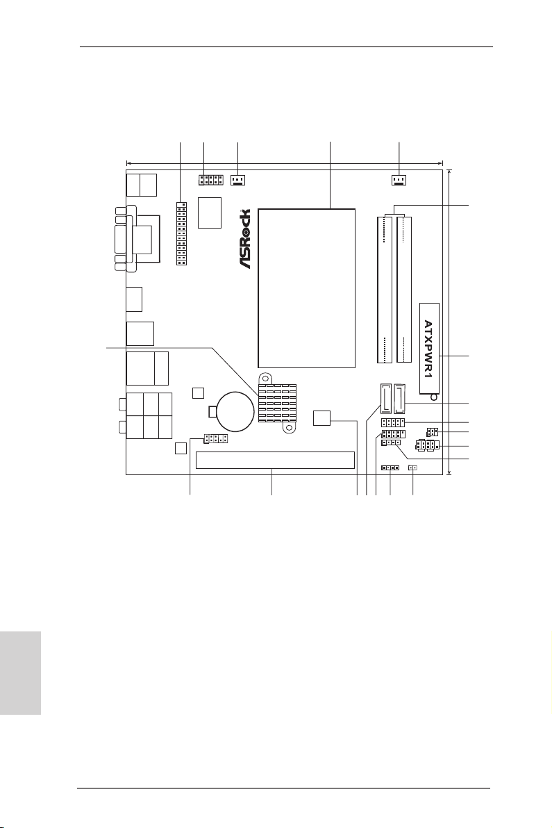
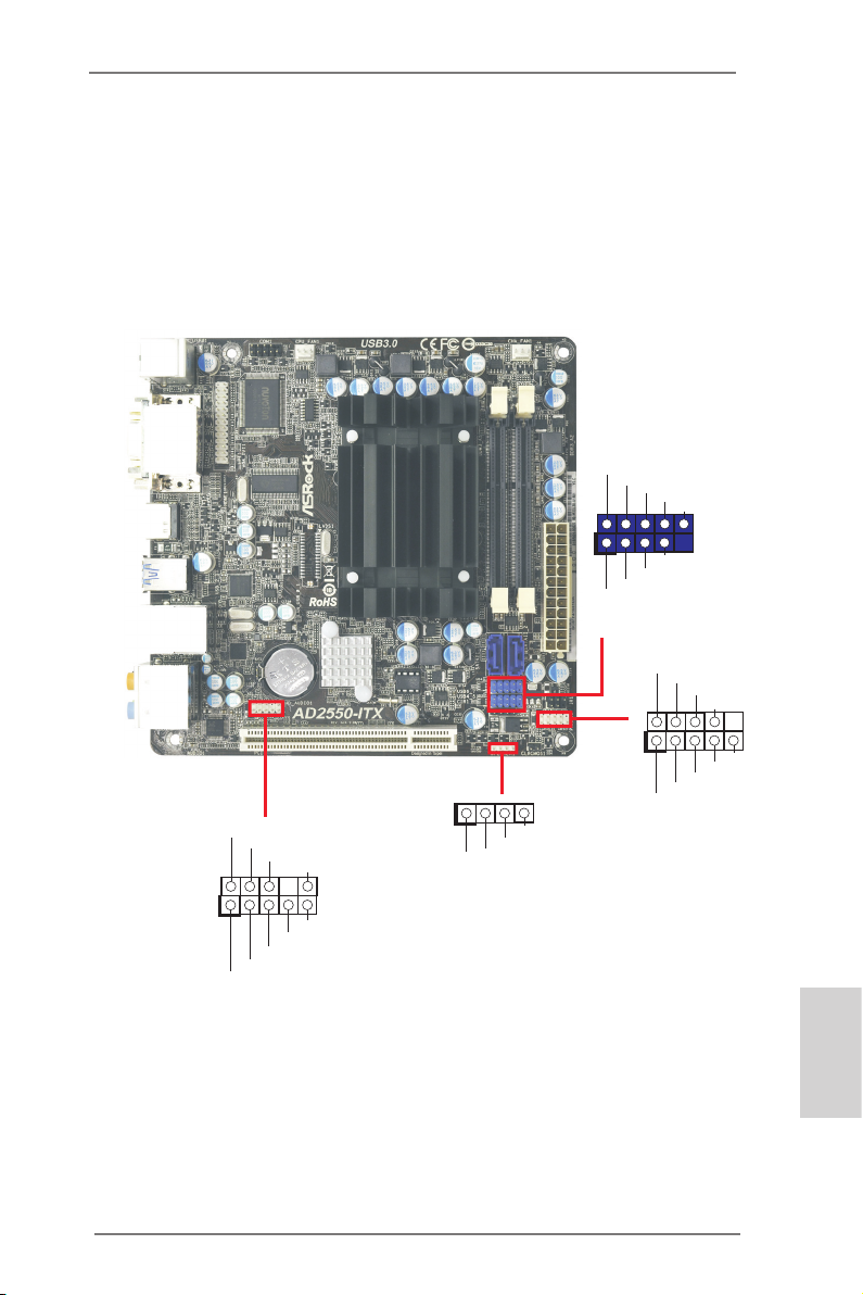
Motherboard Layout
SPEAKER1
1
HD_AUDIO 1
PANEL1
HDLED R ESET
PLED PWRBTN
1
CMO S
Bat ter y
16Mb
BIOS
1
AUDIO
CODEC
17.0c m ( 6.7 in)
17.0c m ( 6.7 in)
Supe r
IO
1
2
4
5
7
6
8
9
10
12
13
14
11
15
16
3
FS B8 00
DDR 3_A 1 (6 4 b it, 204 -pi n mo dul e)
FS B8 00
DDR 3_A 2 (6 4 b it, 204 -pi n mo dul e)
SATAII_1
SATAII_2
LAN
PHY
RoH S
CPU_FAN 1
1
USB8_9
PCI1
1
USB6_7
1
CIR1
1
IR1
CHA_FAN 1
US B 3 .0
AD 25 50-ITX
CLRCMOS1
1
17
18
USB 2.0
T:U SB0
B: USB1
PS2
Keybo ard
VGA 1
DVI _CON 1
HDM I1
USB 2 .0
T: USB4
B: US B5
Top:
RJ-4 5
Top:
CTR BASS
Cente r:
REAR SPK
Botto m:
Optic al
SPDIF
Top:
LINE IN
Cente r:
FRONT
Botto m:
MIC IN
USB 3. 0
T: USB2
B: USB 3
COM1
1
1
LPT1
19
20
English
2
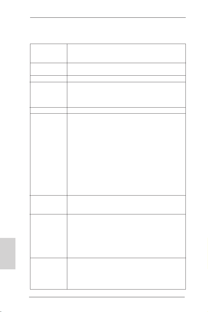
1 Print Port Header (LPT1, White) 12 Consumer Infrared Module Header (CIR1)
2 COM Port Header (COM1) 13 Clear CMOS Jumper (CLRCMOS1)
3 CPU Fan Connector (CPU_FAN1) 14 Chassis Speaker Header
4 CPU Heatsink (SPEAKER 1, White)
5 Chassis Fan Connector (CHA_FAN1) 15 USB 2.0 Header (USB6_7, Blue)
6 2 x 204-pin DDR3 SO-DIMM Slots 16 SATA2 Connector (SATAII_1, Blue)
(DDR3_A1, DDR3_A2, Black) 17 16Mb SPI Flash
7 ATX Power Connector (ATXPWR1) 18 PCI Slot (PCI1)
8 SATA2 Connector (SATAII_2, Blue) 19 Front Panel Audio Header
9 USB 2.0 Header (USB8_9, Blue) (HD_AUDIO1, White)
10 Infrared Module Header (IR1) 20 Intel NM10 Express Chip
11 System Panel Header (PANEL1, White)
ASRock AD2550-ITX Motherboard
Page 3
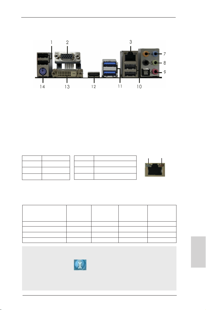
I/O Panel
1 USB 2.0 Ports ** 8 Front Speaker (Lime)
2 D-Sub Port 9 Microphone (Pink)
* 3 LAN RJ-45 Port 10 USB 2.0 Ports
4 Central / Bass (Orange) 11 USB 3.0 Ports (ASMedia ASM1042)
5 Rear Speaker (Black) 12 HDMI Port
6 Optical SPDIF Out Port 13 DVI-D Port
7 Line In (Light Blue) 14 PS/2 Keyboard Port (Purple)
* There are two LED next to the LAN port. Please refer to the table below for the LAN port LED
indications.
Activity/Link LED SPEED LED
Status Description Status Description
Off No Link Off 10Mbps connection
Blinking Data Activity Orange 100Mbps connection
On Link Green 1Gbps connection
LAN Port LED Indications
ACT/LINK
LED
LAN Port
SPEED
LED
If you use 2-channel speaker, please connect the speaker’s plug into “Front Speaker Jack”.
**
See the table below for connection details in accordance with the type of speaker you use.
TABLE for Audio Output Connection
Audio Output Channels Front Speaker Rear Speaker Central / Bass Line In or
(No. 8) (No. 5) (No. 4) Side Speaker
(No. 7)
2 V -- -- -4 V V -- -6 V V V -8 V V V V
To enable Multi-Streaming function, you need to connect a front panel audio cable to the front
panel audio header. After restarting your computer, you will nd “Mixer” tool on your system.
Please select “Mixer ToolBox” , click “Enable playback multi-streaming”, and click
“ok”. Choose “2CH”, “4CH”, “6CH”, or “8CH” and then you are allowed to select “Realtek HDA
Primary output” to use Rear Speaker, Central/Bass, and Front Speaker, or select “Realtek
HDA Audio 2nd output” to use front panel audio.
ASRock AD2550-ITX Motherboard
English
3
Page 4
1. Introduction
Thank you for purchasing ASRock AD2550-ITX motherboard, a reliable motherboard produced under ASRock’s consistently stringent quality control. It delivers
excellent performance with robust design conforming to ASRock’s commitment to
quality and endurance.
This Quick Installation Guide contains introduction of the motherboard and step-bystep installation guide. More detailed information of the motherboard can be found
in the user manual presented in the Support CD.
Because the motherboard specications and the BIOS software might be
updated, the content of this manual will be subject to change without no-
tice. In case any modications of this manual occur, the updated version
will be available on ASRock website without further notice. You may nd
the latest VGA cards and CPU support lists on ASRock website as well.
ASRock website http://www.asrock.com
If you require technical support related to this motherboard, please visit
our website for specic information about the model you are using.
www.asrock.com/support/index.asp
1.1 Package Contents
ASRock AD2550-ITX Motherboard
(Mini-ITX Form Factor: 6.7-in x 6.7-in, 17.0 cm x 17.0 cm)
ASRock AD2550-ITX Quick Installation Guide
ASRock AD2550-ITX Support CD
2 x Serial ATA (SATA) Data Cables (Optional)
1 x I/O Panel Shield
English
4
ASRock AD2550-ITX Motherboard
Page 5
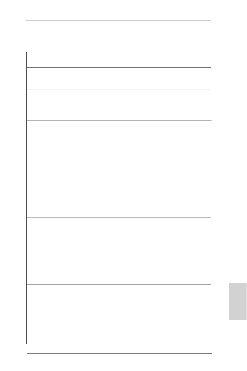
1.2 Specications
Platform - Mini-ITX Form Factor: 6.7-in x 6.7-in, 17.0 cm x 17.0 cm
- All Solid Capacitor design
CPU - Intel® Dual-Core AtomTM Processor D2550 (1.86 GHz)
- Supports Hyper-Threading Technology
Chipset - Southbridge: Intel® NM10 Express
Memory - 2 x DDR3 SO-DIMM slots
- Supports DDR3 1066/800 non-ECC, un-buffered
memory
- Max. capacity of system memory: 4GB (see CAUTION 1)
Expansion Slot - 1 x PCI slot
Graphics - Intel® PowerVR SGX545
- DirectX 9.0, Pixel Shader 3.0
- Three VGA Output options: D-Sub, DVI-D and HDMI
(see CAUTION 2)
- Supports HDMI 1.3a Technology with max. resolution up to
1920x1200
- Supports DVI with max. resolution up to 1920x1200 @ 60Hz
- Supports D-Sub with max. resolution up to 1920x1200 @
60Hz
- Supports HDCP function with DVI and HDMI ports
- Supports Full HD 1080p Blu-ray (BD) / HD-DVD playback
with DVI and HDMI ports
Audio - 7.1 CH HD Audio with Content Protection
(Realtek ALC892 Audio Codec)
- Premium Blu-ray audio support
LAN - PCIE x1 Gigabit LAN 10/100/1000 Mb/s
- Realtek RTL8111E
- Supports Wake-On-LAN
- Supports LAN Cable Detection
- Supports Energy Efcient Ethernet 802.3az
- Supports PXE
Rear Panel I/O I/O Panel
- 1 x PS/2 Keyboard Port
- 1 x D-Sub Port
- 1 x DVI-D Port
- 1 x HDMI Port
- 1 x Optical SPDIF Out Port
- 4 x USB 2.0 Ports
- 2 x USB 3.0 Ports (ASMedia ASM1042)
English
ASRock AD2550-ITX Motherboard
5
Page 6
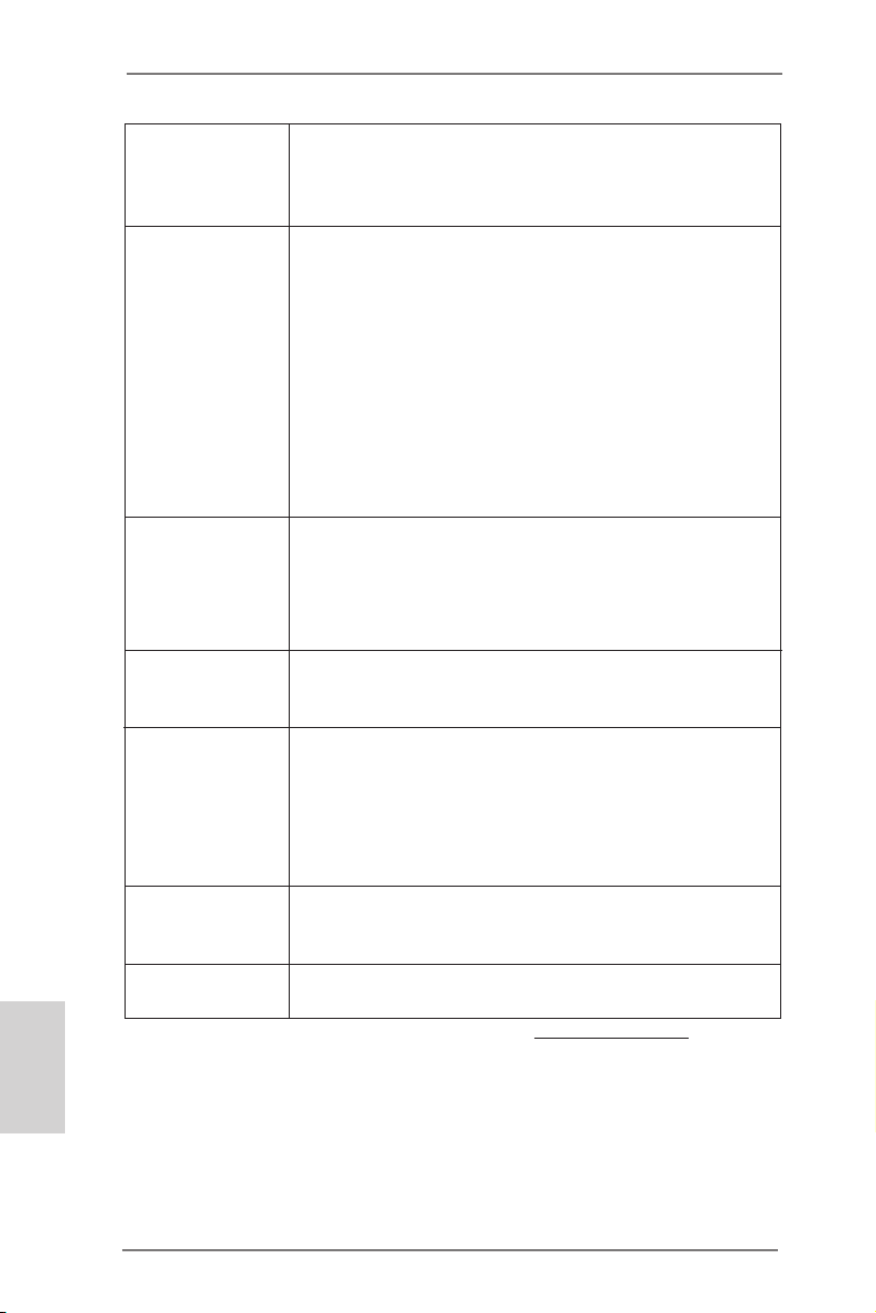
English
- 1 x RJ-45 LAN Port with LED (ACT/LINK LED and SPEED
LED)
- HD Audio Jack: Rear Speaker/Central/Bass/Line in/Front
Speaker/Microphone
Connector - 2 x SATA2 3.0 Gb/s connectors, support NCQ, AHCI and
Hot Plug functions
- 1 x IR header
- 1 x CIR header
- 1 x Print Port header
- 1 x COM port header
- 1 x CPU Fan connector (3-pin)
- 1 x Chassis Fan connector (3-pin)
- 1 x 24 pin ATX power connector
- 1 x Front panel audio connector
- 2 x USB 2.0 headers (support 4 USB 2.0 ports)
BIOS Feature - 16Mb AMI UEFI Legal BIOS with GUI support
- Supports “Plug and Play”
- ACPI 1.1 Compliance Wake Up Events
- Supports jumperfree
- SMBIOS 2.3.1 Support
Support CD - Drivers, Utilities, AntiVirus Software (Trial Version),
CyberLink MediaEspresso 6.5 Trial, Google Chrome
Browser and Toolbar
Hardware - CPU Temperature Sensing
Monitor - Chassis Temperature Sensing
- CPU Fan Tachometer
- Chassis Fan Tachometer
- CPU/Chassis Quiet Fan
- Voltage Monitoring: +12V, +5V, +3.3V, CPU Vcore
OS - Microsoft® Windows® 7 32-bit compliant
* Due to lack of Intel® 64-bit VGA driver support, this
motherboard does not support 64-bit OS.
Certications - FCC, CE, WHQL
- ErP/EuP Ready (ErP/EuP ready power supply is required)
* For detailed product information, please visit our website: http://www.asrock.com
6
ASRock AD2550-ITX Motherboard
Page 7

WARNING
Please realize that there is a certain risk involved with overclocking, including
adjusting the setting in the BIOS, applying Untied Overclocking Technology, or
using the third-party overclocking tools. Overclocking may affect your system
stability, or even cause damage to the components and devices of your system.
It should be done at your own risk and expense. We are not responsible for possible
damage caused by overclocking.
CAUTION!
1. Due to the chipset limitation, the actual memory size may be less than
4GB for the reservation for system usage under Windows® OS.
2. You can choose to use two of the three monitors only. D-Sub, DVI-D and
HDMI monitors cannot be enabled at the same time. Besides, with the
DVI-to-HDMI adapter, the DVI-D port can support the same features as
HDMI port.
ASRock AD2550-ITX Motherboard
English
7
Page 8

1.3 Unique Features
ASRock Instant Boot
ASRock Instant Boot allows you to turn on your PC in just a few
seconds, provides a much more efcient way to save energy,
time, money, and improves system running speed for your system. It leverages the S3 and S4 ACPI features which normally
enable the Sleep/Standby and Hibernation modes in Windows®
to shorten boot up time. By calling S3 and S4 at specic timing
during the shutdown and startup process, Instant Boot allows
you to enter your Windows® desktop in a few seconds.
ASRock Instant Flash
ASRock Instant Flash is a BIOS ash utility embedded in Flash
ROM. This convenient BIOS update tool allows you to update
system BIOS without entering operating systems rst like MS-
DOS or Windows®. With this utility, you can press the <F6> key
during the POST or the <F2> key to enter into the BIOS setup
menu to access ASRock Instant Flash. Just launch this tool and
save the new BIOS le to your USB ash drive, oppy disk or
hard drive, then you can update your BIOS only in a few clicks
without preparing an additional oppy diskette or other complicated ash utility. Please be noted that the USB ash drive or
hard drive must use FAT32/16/12 le system.
English
8
ASRock APP Charger
If you desire a faster, less restricted way of charging your
Apple devices, such as iPhone/iPad/iPod Touch, ASRock has
prepared a wonderful solution for you - ASRock APP Charger.
Simply install the APP Charger driver, it makes your iPhone
charge much quickly from your computer and up to 40% faster
than before. ASRock APP Charger allows you to quickly charge
many Apple devices simultaneously and even supports continuous charging when your PC enters into Standby mode (S1),
Suspend to RAM (S3), hibernation mode (S4) or power off (S5).
With APP Charger driver installed, you can easily enjoy the marvelous charging experience.
ASRock AD2550-ITX Motherboard
Page 9

ASRock XFast USB
ASRock XFast USB can boost USB storage device perfor-
mance. The performance may depend on the properties of the
device.
ASRock XFast LAN
ASRock XFast LAN provides a faster internet access, which
includes the benefits listed below. LAN Application Prioritiza-
tion: You can congure your application’s priority ideally and/or
add new programs. Lower Latency in Game: After setting online
game’s priority higher, it can lower the latency in games. Trafc
Shaping: You can watch Youtube HD videos and download simultaneously. Real-Time Analysis of Your Data: With the status
window, you can easily recognize which data streams you are
transferring currently.
ASRock XFast RAM
ASRock XFast RAM is a new function that is included into AS-
Rock Extreme Tuning Utility (AXTU). It fully utilizes the memory
space that cannot be used under Windows® OS 32-bit CPU.
ASRock XFast RAM shortens the loading time of previously
visited websites, making web surfing faster than ever. And it
also boosts the speed of Adobe Photoshop 5 times faster. Another advantage of ASRock XFast RAM is that it reduces the
frequency of accessing your SSDs or HDDs in order to extend
their lifespan.
ASRock On/Off Play Technology
ASRock On/Off Play Technology allows users to enjoy the great
audio experience from the portable audio devices, such like
MP3 player or mobile phone to your PC, even when the PC is
turned off (or in ACPI S5 mode)! This motherboard also provides
a free 3.5mm audio cable (optional) that ensures users the most
convenient computing environment.
ASRock AD2550-ITX Motherboard
English
9
Page 10

2. Installation
This is a Mini-ITX form factor (6.7" x 6.7", 17.0 x 17.0 cm) motherboard. Before you
install the motherboard, study the conguration of your chassis to ensure that the
motherboard ts into it.
English
motherboard. Failure to do so may cause physical injuries to you and
damages to motherboard components.
Make sure to unplug the power cord before installing or removing the
2.1 Screw Holes
Place screws into the holes indicated by circles to secure the motherboard to the
chassis.
Do not over-tighten the screws! Doing so may damage the motherboard.
2.2 Pre-installation Precautions
Take note of the following precautions before you install motherboard components
or change any motherboard settings.
1. Unplug the power cord from the wall socket before touching any component.
2. To avoid damaging the motherboard components due to static electricity,
NEVER place your motherboard directly on the carpet or the like. Also
remember to use a grounded wrist strap or touch a safety grounded object
before you handle components.
3. Hold components by the edges and do not touch the ICs.
4. Whenever you uninstall any component, place it on a grounded antistatic pad or
in the bag that comes with the component.
Before you install or remove any component, ensure that the power is
switched off or the power cord is detached from the power supply.
Failure to do so may cause severe damage to the motherboard, peripherals,
and/or components.
10
ASRock AD2550-ITX Motherboard
Page 11
2.3 Installation of Memory Modules (SO-DIMM)
AD2550-ITX motherboard provides two 204-pin DDR3 (Double Data Rate 3) SODIMM slots.
1. It is not allowed to install a DDR or DDR2 memory module into DDR3
slot; otherwise, this motherboard and SO-DIMM may be damaged.
2. Please install the memory module from DDR3_A2 slot for the rst
priority.
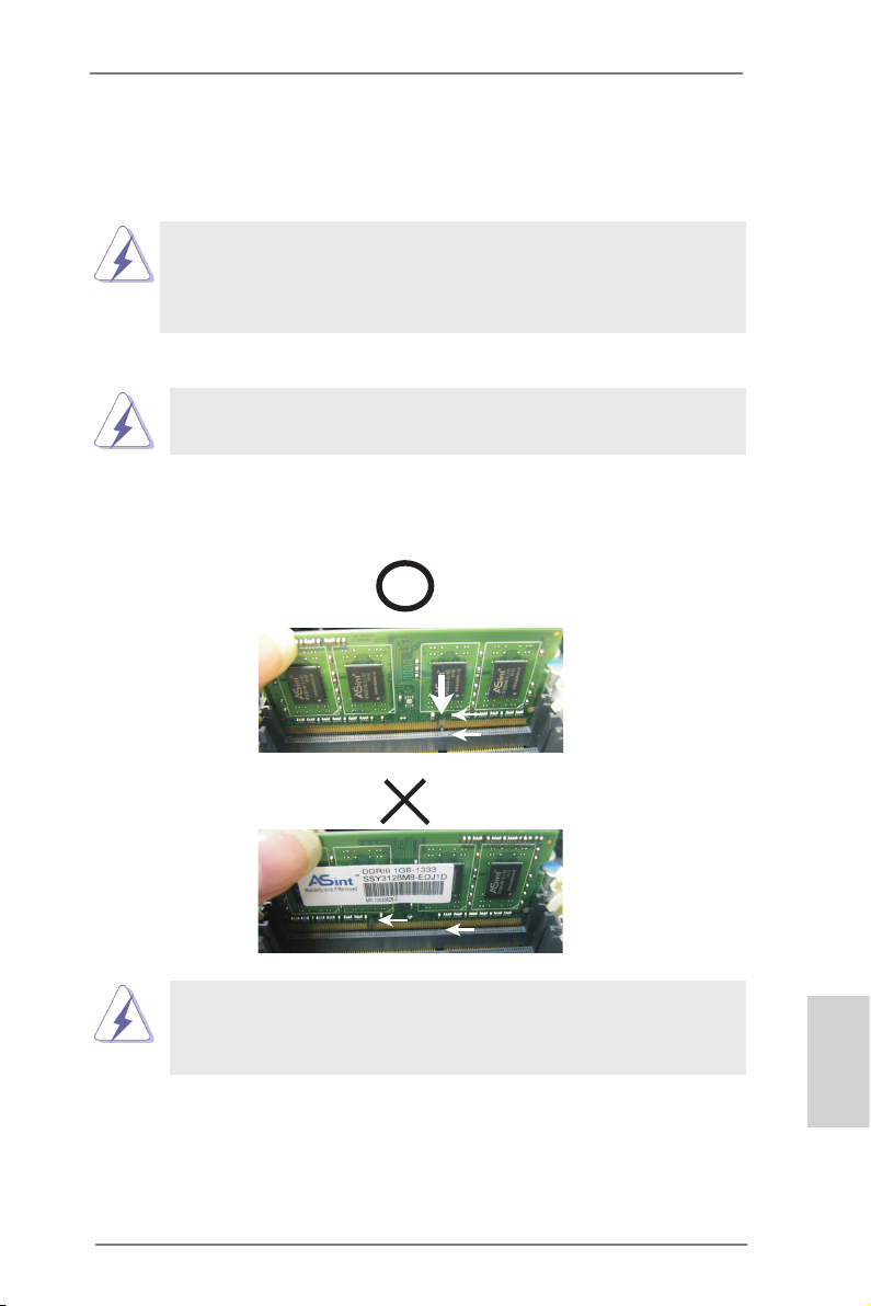
Installing a SO-DIMM
Please make sure to disconnect power supply before adding or
removing SO-DIMMs or the system components.
Step 1. Unlock a SO-DIMM slot by pressing the retaining clips outward.
Step 2. Align a SO-DIMM on the slot such that the notch on the SO-DIMM
matches the break on the slot.
notch
break
notch
The SO-DIMM only ts in one correct orientation. It will cause permanent damage to the motherboard and the SO-DIMM if you force the SODIMM into the slot at incorrect orientation.
break
Step 3. Firmly insert the SO-DIMM into the slot until the retaining clips at both
ends fully snap back in place and the SO-DIMM is properly seated.
ASRock AD2550-ITX Motherboard
English
11
Page 12

2.4 Expansion Slot (PCI Slot)
There is 1 PCI slot on this motherboard.
PCI slot: The PCI slot is used to install expansion card that has the 32-bit PCI
interface.
Installing an expansion card
Step 1. Before installing the expansion card, please make sure that the power
supply is switched off or the power cord is unplugged. Please read the
documentation of the expansion card and make necessary hardware
settings for the card before you start the installation.
Step 2. Remove the system unit cover (if your motherboard is already installed
in a chassis).
Step 3. Remove the bracket facing the slot that you intend to use. Keep the
screws for later use.
Step 4. Align the card connector with the slot and press rmly until the card is
completely seated on the slot.
Step 5. Fasten the card to the chassis with screws.
Step 6. Replace the system cover.
English
12
ASRock AD2550-ITX Motherboard
Page 13
2.5 Pin Header Easy Installation Guide
1
PLE D+
PLE D-
PWR BTN #
HDL ED+
HDL ED-
GND
RES T#
GND
DUM MY
1
+5V
DUM MY
SPE AKE R
DUM MY
1
GND
PRE SEN CE#
MIC _RE T
MIC 2_L
MIC 2_R
OUT 2_R
J_S ENS E
OUT 2_L
OUT _RE T
1
USB _PW R
P-
P+
USB _PW R
P-
P+
GND
GND
DUM MY
ASRock motherboard is equipped with pin headers with obvious colors which indicate you to recognize the crucial headers more easily. Please refer to below illustra-
tions for the pin denition of onboard headers. If you want to have more information
about the usage of these headers, please refer to “Jumpers Setup“ and “Onboard
Headers and Connectors“ for details.
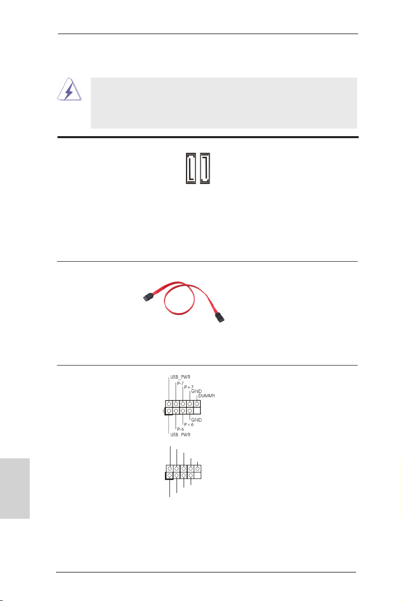
Front Panel Audio Header
ASRock AD2550-ITX Motherboard
USB 2.0 Header
Chassis Speaker Header
System Panel Header
English
13
Page 14
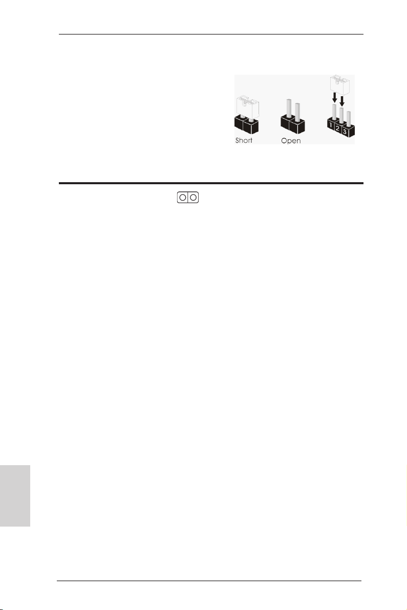
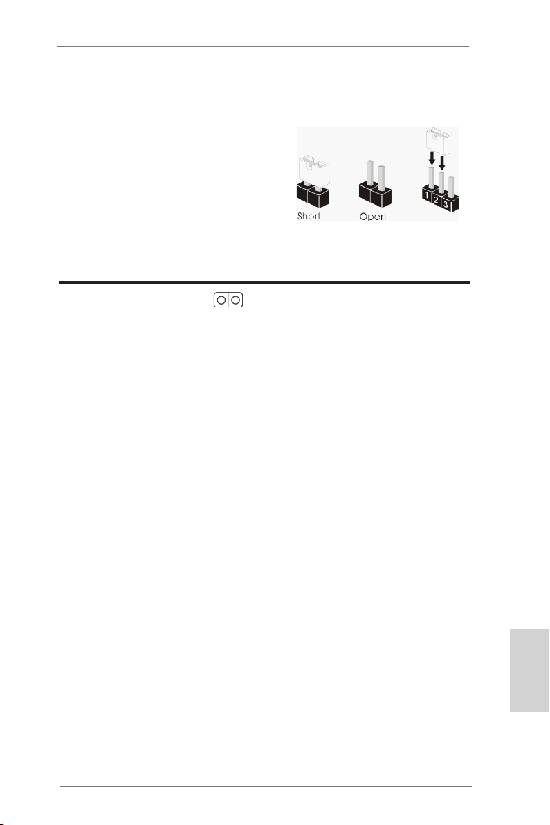
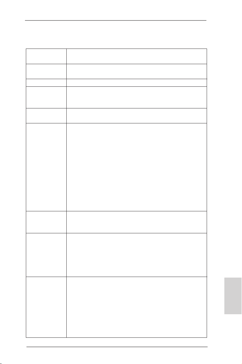
2.6 Jumpers Setup
The illustration shows how jumpers are
setup. When the jumper cap is placed on
pins, the jumper is “Short”. If no jumper cap
is placed on pins, the jumper is “Open”. The
illustration shows a 3-pin jumper whose
pin1 and pin2 are “Short” when jumper cap
is placed on these 2 pins.
Jumper Setting Description
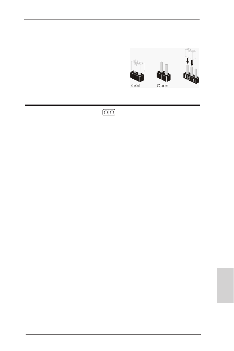
Clear CMOS
(CLRCMOS1, 2-pin jumper)
(see p.2 No. 13)
Note: CLRCMOS1 allows you to clear the data in CMOS. The data in CMOS in-
cludes system setup information such as system password, date, time, and
system setup parameters. To clear and reset the system parameters to default setup, please turn off the computer and unplug the power cord from the
power supply. After waiting for 15 seconds, use a jumper cap to short 2 pins
on CLRCMOS1 for 5 seconds.
2-pin jumper
English
14
ASRock AD2550-ITX Motherboard
Page 15
2.7 Onboard Headers and Connectors
Onboard headers and connectors are NOT jumpers. Do NOT place
jumper caps over these headers and connectors. Placing jumper caps
over the headers and connectors will cause permanent damage of the
motherboard!
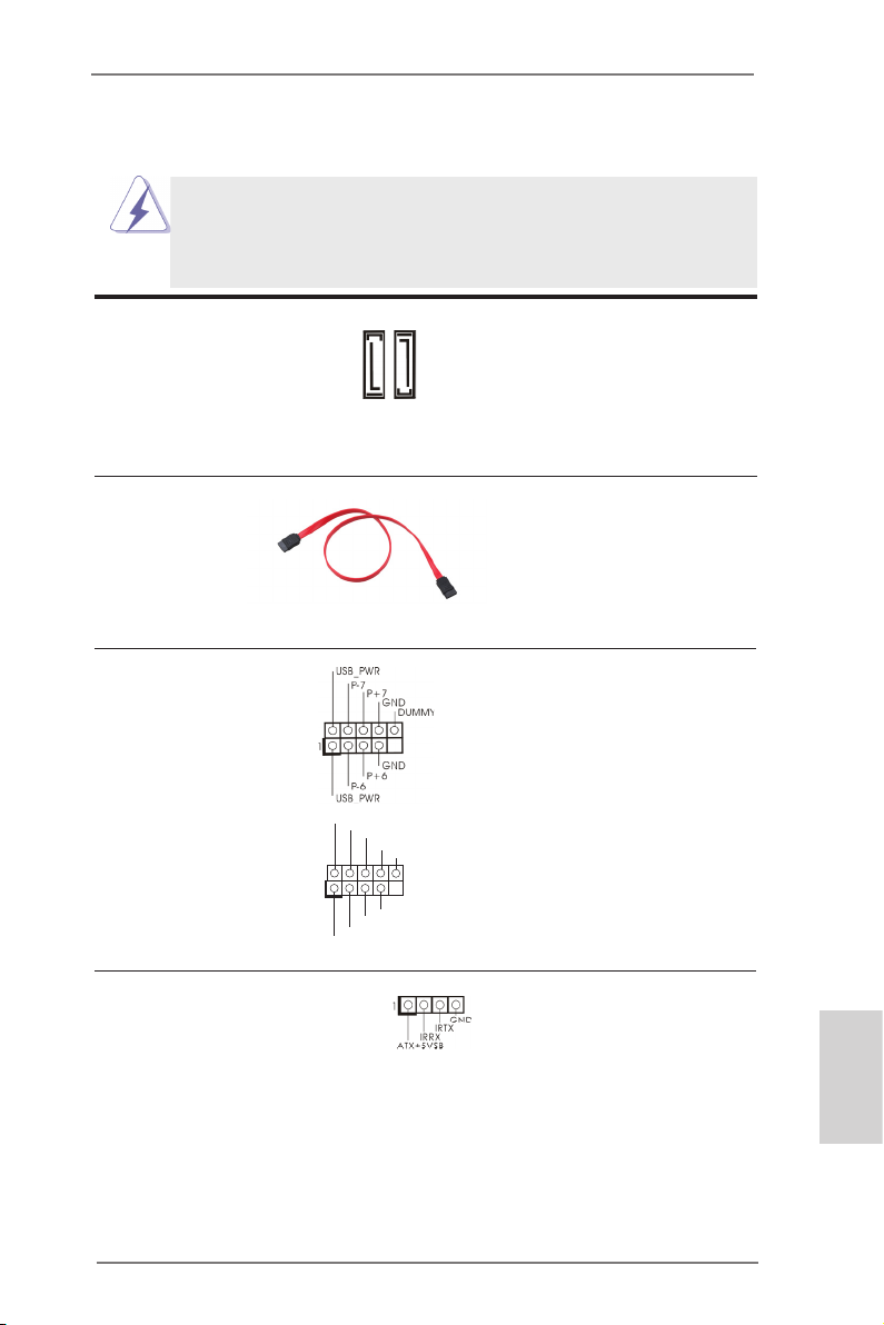
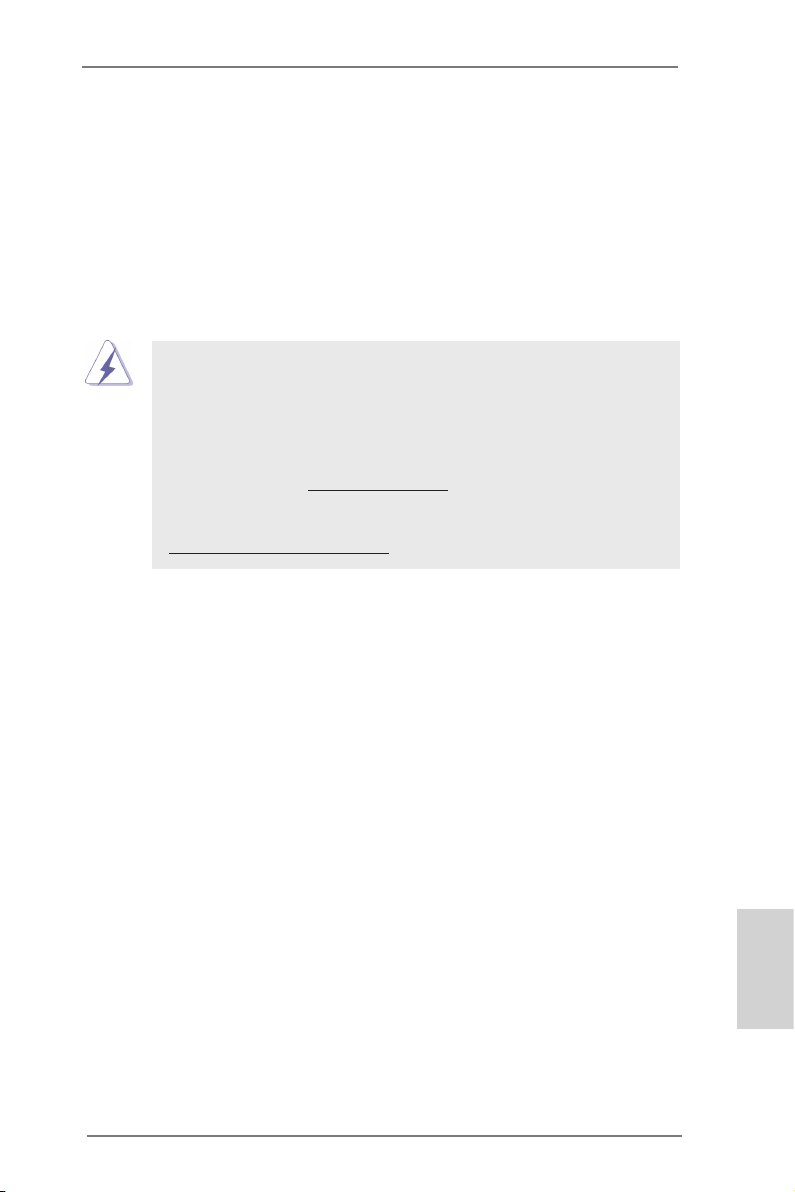
Serial ATA2 Connectors These two Serial ATA2 (SATA2)
(SATAII_1: see p.2, No. 16)
(SATAII_2: see p.2, No. 8)
devices. The current SATA2
interface allows up to 3.0 Gb/s
data transfer rate.
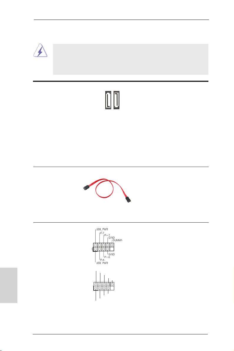
Serial ATA (SATA) Either end of the SATA data
Data Cable cable can be connected to the
(Optional)
SATA / SATA2 hard disk or the
SATA2 connector on this
motherboard.
USB 2.0 Headers Besides the default USB 2.0
(9-pin USB6_7)
(see p.2 No. 15)
ports on the I/O panel, there
this motherboard. Each
USB 2.0 header can support
two USB 2.0 ports.
(9-pin USB8_9)
(see p.2 No. 9)
connectors support SATA data
cables for internal storage
SATAII_1
SATAII_2
are two USB 2.0 headers on
USB _PWR
P-9
P+9
GND
DUM MY
1
GND
P+8
P-8
USB _PWR
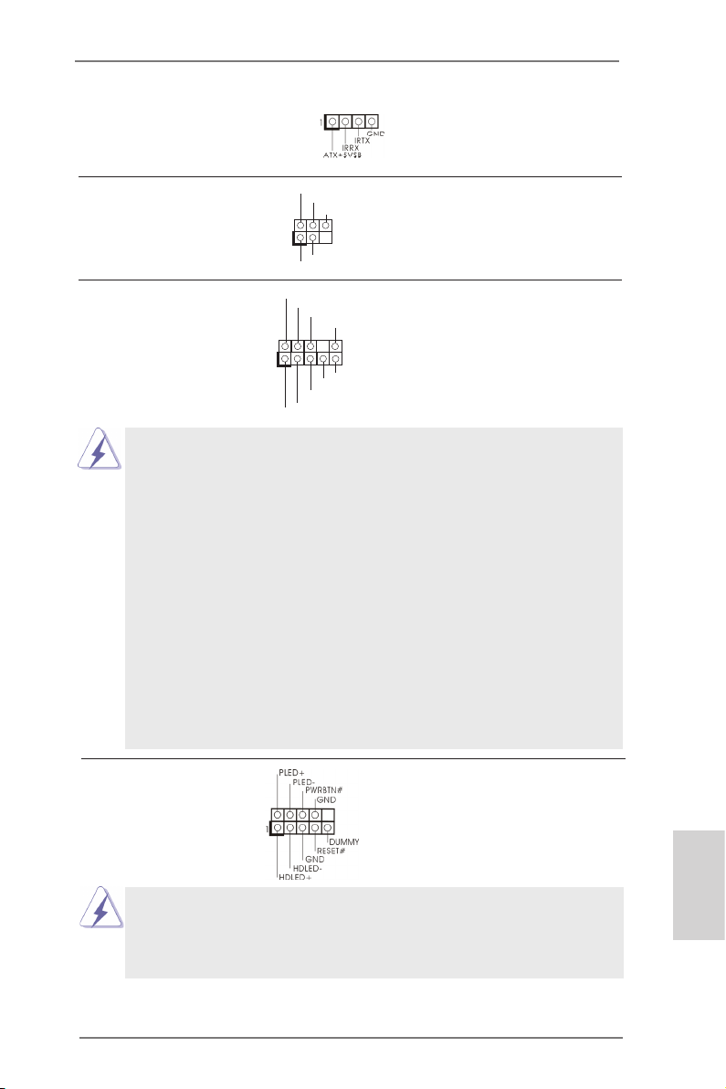
Consumer Infrared Module Header This header can be used to
(4-pin CIR1)
(see p.2 No. 12)
connect the remote controller
receiver.
ASRock AD2550-ITX Motherboard
English
15
Page 16
Infrared Module Header This header supports an
1
IRTX
+5VS B
DUMM Y
IRRX
GND
(5-pin IR1)
optional wireless transmitting
(see p.2 No. 10)
and receiving infrared module.
1
GND
PRE SENC E#
MIC 2_R
MIC 2_L
MIC _RET
J_S ENSE
OUT 2_R
OUT _RET
OUT 2_L
Front Panel Audio Header This is an interface for front
(9-pin HD_AUDIO1)
(see p.2 No. 19)
panel audio cable that allows
convenient connection and
control of audio devices.
1. High Denition Audio supports Jack Sensing, but the panel wire on
the chassis must support HDA to function correctly. Please follow the
instruction in our manual and chassis manual to install your system.
2. If you use AC’97 audio panel, please install it to the front panel audio
header as below:
A. Connect Mic_IN (MIC) to MIC2_L.
B. Connect Audio_R (RIN) to OUT2_R and Audio_L (LIN) to OUT2_L.
C. Connect Ground (GND) to Ground (GND).
D. MIC_RET and OUT_RET are for HD audio panel only. You don’t
need to connect them for AC’97 audio panel.
E. To activate the front mic.
Go to the "FrontMic" Tab in the Realtek Control panel. Adjust
“Recording Volume”.
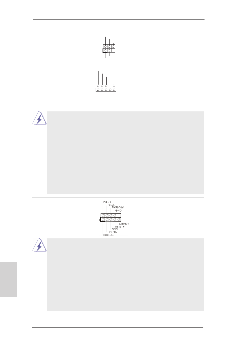
System Panel Header This header accommodates
(9-pin PANEL1)
(see p.2 No. 11)
several system front panel
functions.
English
Connect the power switch, reset switch and system status indicator on the
chassis to this header according to the pin assignments below. Note the
positive and negative pins before connecting the cables.
PWRBTN (Power Switch):
Connect to the power switch on the chassis front panel. You may congure
the way to turn off your system using the power switch.
RESET (Reset Switch):
Connect to the reset switch on the chassis front panel. Press the reset
switch to restart the computer if the computer freezes and fails to perform a
normal restart.
16
ASRock AD2550-ITX Motherboard
Page 17
PLED (System Power LED):
Connect to the power status indicator on the chassis front panel. The LED
is on when the system is operating. The LED keeps blinking when the system is in S1 sleep state. The LED is off when the system is in S3/S4 sleep
state or powered off (S5).
HDLED (Hard Drive Activity LED):
Connect to the hard drive activity LED on the chassis front panel. The LED
is on when the hard drive is reading or writing data.
The front panel design may differ by chassis. A front panel module mainly
consists of power switch, reset switch, power LED, hard drive activity LED,
speaker and etc. When connecting your chassis front panel module to this
header, make sure the wire assignments and the pin assign-ments are
matched correctly.
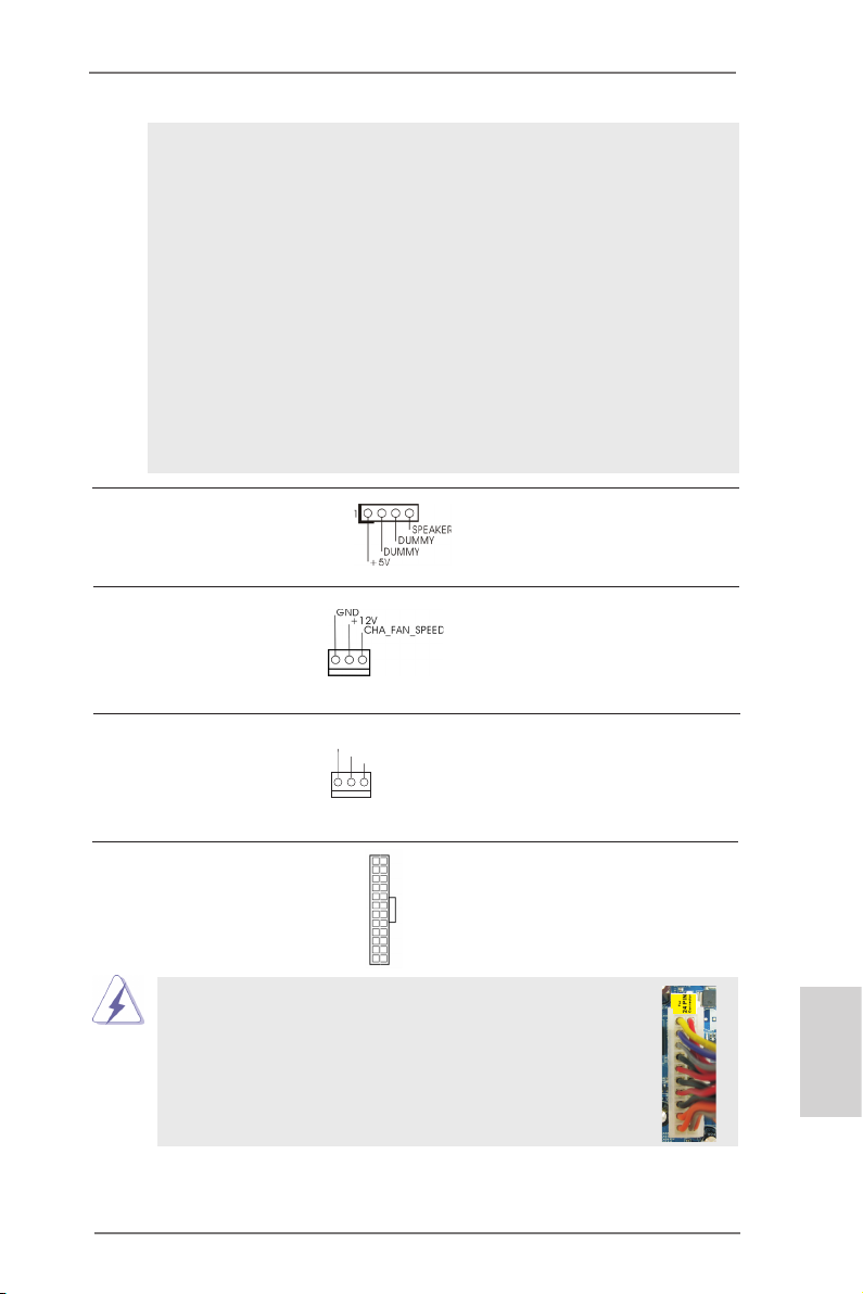
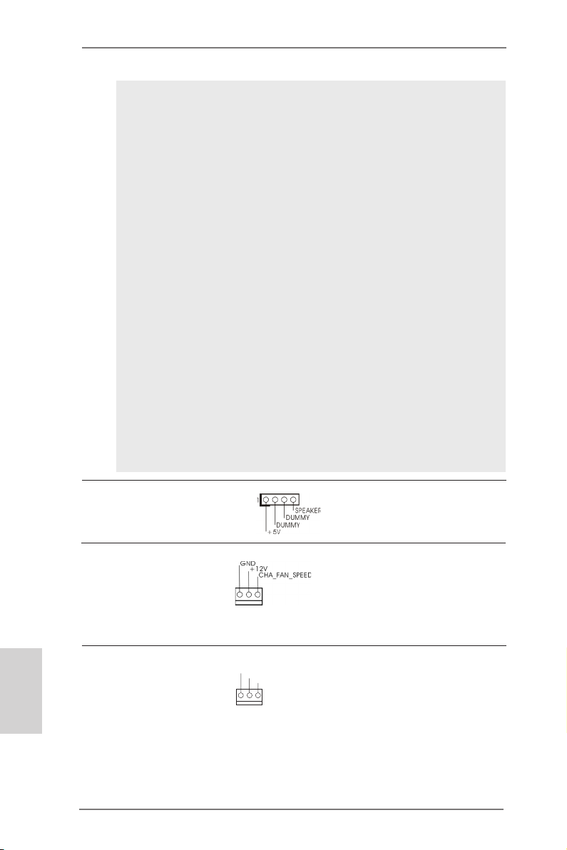
Chassis Speaker Header Please connect the chassis
(4-pin SPEAKER 1)
(see p.2 No. 14)
speaker to this header.
Chassis Fan Connector Please connect the fan cable
(3-pin CHA_FAN1)
(see p.2 No. 5)
to the fan connector and
match the black wire to the
ground pin.
CPU Fan Connector Please connect the CPU fan
(3-pin CPU_FAN1)
(see p.2 No. 3)
cable to the connector and
match the black wire to the
GND
+12 V
CPU _FAN_ SPEE D
ground pin.
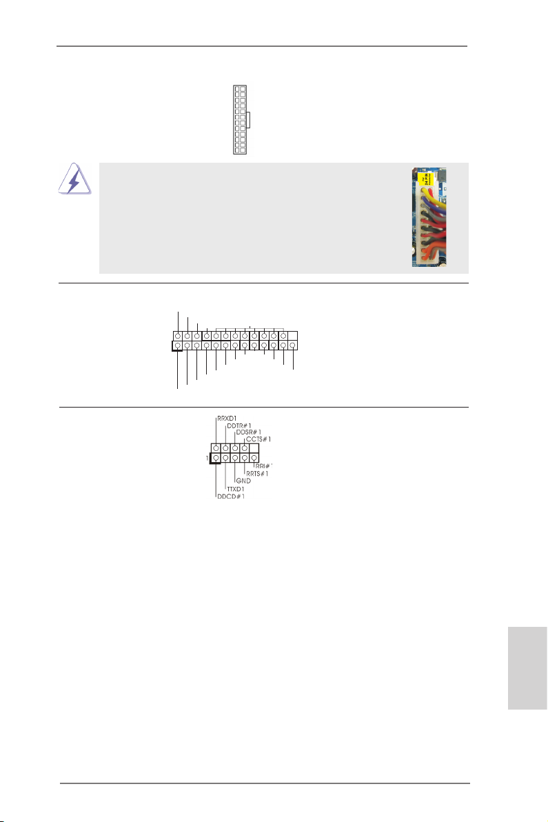
ATX Power Connector Please connect an ATX power
(24-pin ATXPWR1)
(see p.2 No. 7)
supply to this connector.
Though this motherboard provides 24-pin ATX power connector,
it can still work if you adopt a traditional 20-pin ATX power supply.
To use the 20-pin ATX power supply, please plug your
power supply along with Pin 1 and Pin 13.
12 124
13
20-Pin ATX Power Supply Installation
12
1
ASRock AD2550-ITX Motherboard
24
English
13
17
Page 18
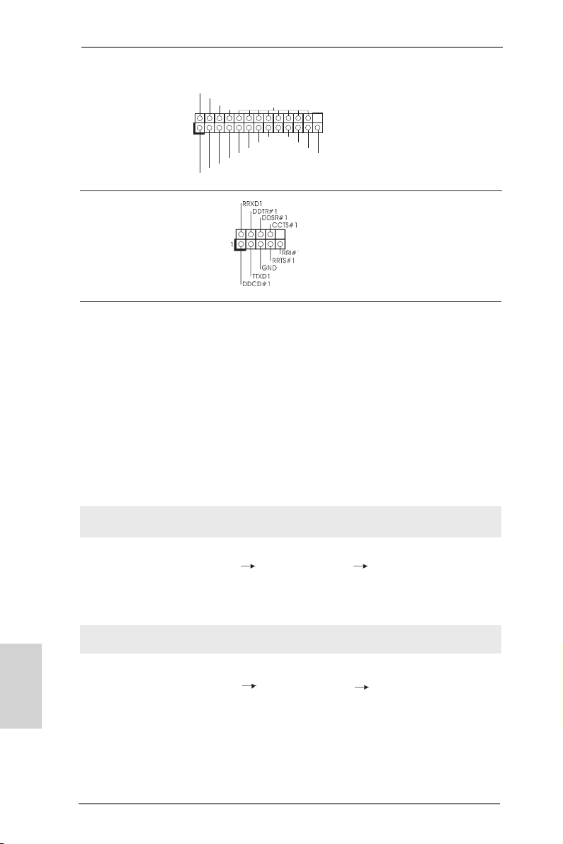
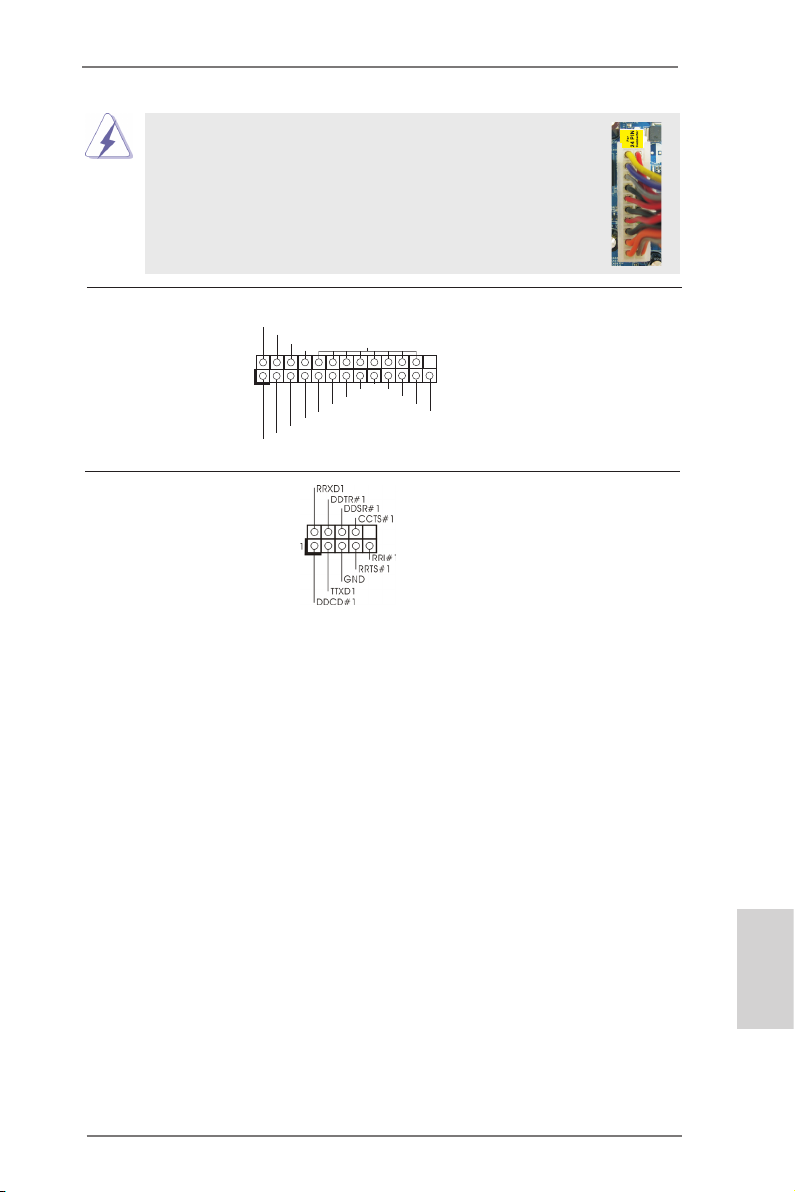
Print Port Header This is an interface for print
(25-pin LPT1)
(see p.2 No. 1)
port cable that allows
convenient connection of printer
devices.
1
AFD #
STB #
ERR OR#
PIN I T#
SPD 1
SPD 0
SLI N #
SPD 2
SPD 3
SPD 4
SPD 5
SPD 6
GND
SPD 7
ACK #
BUS Y
PE
SLC T
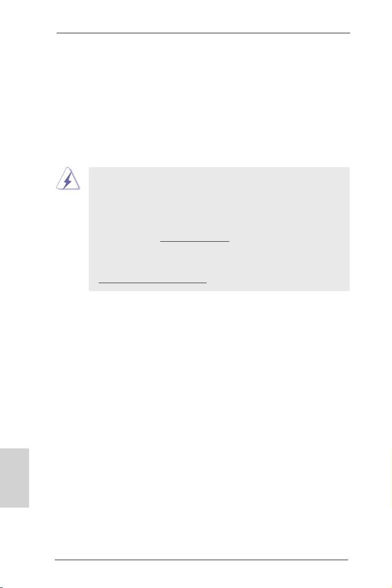
Serial port Header This COM1 header supports a
(9-pin COM1)
(see p.2 No. 2)
serial port module.
2.8 Driver Installation Guide
To install the drivers to your system, please insert the support CD to your optical
drive rst. Then, the drivers compatible to your system can be auto-detected and
listed on the support CD driver page. Please follow the order from up to bottom side
to install those required drivers. Therefore, the drivers you install can work properly.
2.9 Installing Windows® 7 on SATA / SATAII HDDs
If you want to install Windows® 7 OS on your SATA / SATAII HDDs, please follow
below steps.
English
18
Using SATA / SATAII HDDs with NCQ function
STEP 1: Set up UEFI.
A. Enter UEFI SETUP UTILITY Advanced screen Storage Conguration.
B. Set the option “SATA Mode” to [AHCI].
STEP 2: Install Windows® 7 OS on your system.
Using SATA / SATAII HDDs without NCQ function
STEP 1: Set up UEFI.
A. Enter UEFI SETUP UTILITY Advanced screen Storage Conguration.
B. Set the option “SATA Mode” to [IDE].
STEP 2: Install Windows® 7 OS on your system.
ASRock AD2550-ITX Motherboard
Page 19

3. BIOS Information
The Flash Memory on the motherboard stores BIOS Setup Utility. When you start up
the computer, please press <F2> or <Del> during the Power-On-Self-Test (POST)
to enter BIOS Setup utility; otherwise, POST continues with its test routines. If you
wish to enter BIOS Setup after POST, please restart the system by pressing <Ctl>
+ <Alt> + <Delete>, or pressing the reset button on the system chassis. The BIOS
Setup program is designed to be user-friendly. It is a menu-driven program, which
allows you to scroll through its various sub-menus and to select among the predetermined choices. For the detailed information about BIOS Setup, please refer to the
User Manual (PDF le) contained in the Support CD.
4. Software Support CD information
®
This motherboard supports various Microsoft
bit. The Support CD that came with the motherboard contains necessary drivers and
useful utilities that will enhance motherboard features. To begin using the Support
CD, insert the CD into your CD-ROM drive. It will display the Main Menu automatically if “AUTORUN” is enabled in your computer. If the Main Menu does not appear
automatically, locate and double-click on the file “ASSETUP.EXE” from the BIN
folder in the Support CD to display the menus.
Windows® operating systems: 7 32-
ASRock AD2550-ITX Motherboard
English
19
Page 20
1. Einführung
Wir danken Ihnen für den Kauf des ASRock AD2550-ITX Motherboard, ein zuverlässiges Produkt, welches unter den ständigen, strengen Qualitätskontrollen von
ASRock gefertigt wurde. Es bietet Ihnen exzellente Leistung und robustes Design,
gemäß der Verpflichtung von ASRock zu Qualität und Halbarkeit. Diese Schnellinstallationsanleitung führt in das Motherboard und die schrittweise Installation
ein. Details über das Motherboard nden Sie in der Bedienungsanleitung auf der
Support-CD.
Da sich Motherboard-Spezikationen und BIOS-Software verändern
können, kann der Inhalt dieses Handbuches ebenfalls jederzeit geändert
werden. Für den Fall, dass sich Änderungen an diesem Handbuch
ergeben, wird eine neue Version auf der ASRock-Website, ohne weitere
Ankündigung, verfügbar sein. Die neuesten Grakkarten und unterstützten
CPUs sind auch auf der ASRock-Website aufgelistet.
ASRock-Website: http://www.asrock.com
Wenn Sie technische Unterstützung zu Ihrem Motherboard oder spezische
Informationen zu Ihrem Modell benötigen, besuchen Sie bitte unsere
Webseite:
www.asrock.com/support/index.asp
1.1 Kartoninhalt
ASRock AD2550-ITX Motherboard
(Mini-ITX-Formfaktor: 17.0 cm x 17.0 cm; 6.7 Zoll x 6.7 Zoll)
ASRock AD2550-ITX Schnellinstallationsanleitung
ASRock AD2550-ITX Support-CD
Zwei Serial ATA (SATA) -Datenkabel (optional)
Ein I/O Shield
Deutsch
20
ASRock AD2550-ITX Motherboard
Page 21
1.2 Spezikationen
Plattform - Mini-ITX-Formfaktor: 17.0 cm x 17.0 cm; 6.7 Zoll x 6.7 Zoll
- Alle Feste Kondensatordesign
CPU - Intel® Dual-Core AtomTM-Prozessor D2550 (1.86 GHz)
- Unterstützt Hyper-Threading-Technologie
Chipsatz - Southbridge: Intel® NM10 Express
Speicher - 2 x SO-DIMM für DDR3
- Unterstützt DDR3 1066/800 non-ECC, ungepufferter
Speicher
- Max. Kapazität des Systemspeichers: 4GB
Erweiterungs- - 1 x PCI -Steckplätze
steckplätze
Onboard-VGA - Intel® PowerVR SGX545
- DirectX 9.0, Pixel Shader 3.0
- Drei VGA-Ausgangsoptionen: D-Sub, DVI-D sowie HDMI
- Unterstützt HDMI 1.3a mit einer maximalen Auösung von
1920 x 1200
- Unterstützt DVI-D mit einer maximalen Auösung von
1920 x 1200 bei 60 Hz
- Unterstützt D-Sub mit einer maximalen Auösung von
1920 x 1200 bei 60 Hz
- Unterstützt HDCP-Funktion mit DVI-D- und HDMI-Ports
- Unterstutzt 1080p Blu-ray (BD) / HD-DVD-Wiedergabe mit
DVI-D- und HDMI-Ports
Audio - 7.1 CH HD Audio mit dem Inhalt Schutz
(Realtek ALC892 Audio Codec)
- Premium Blu-ray-Audio-Unterstützung
LAN - PCIE x1 Gigabit LAN 10/100/1000 Mb/s
- Realtek RTL8111E
- Unterstützt Wake-On-LAN
- Unterstützt LAN-Kabelerkennung
- Unterstützt energieefzientes Ethernet 802.3az
- Unterstützt PXE
E/A-Anschlüsse I/O Panel
an der - 1 x PS/2-Tastaturanschluss
Rückseite - 1 x D-Sub port
- 1 x DVI-D port
- 1 x HDMI port
- 1 x optischer SPDIF-Ausgang
- 4 x Standard-USB 2.0-Anschlüsse
Deutsch
ASRock AD2550-ITX Motherboard
21
Page 22

Deutsch
- 2 x Standard-USB 3.0-Anschlüsse (ASMedia ASM1042)
- 1 x RJ-45 LAN Port mit LED (ACT/LINK LED und SPEED
LED)
- HD Audiobuchse: Lautsprecher hinten / Mitte/Bass /
Audioeingang / Lautsprecher vorne / Mikrofon
Anschlüsse - 2 x SATA2 3,0 GB/s-Anschlüsse, unterstützen NCQ-, AHCI-
und „Hot Plug“ (Hot-Plugging)- Funktionen
- 1 x Infrarot-Modul-Header
- 1 x Consumer Infrared-Modul-Header
- 1 x Druckerport-Anschlussleiste
- 1 x COM-Anschluss-Header
- 1 x CPUlüfter-Anschluss (3-pin)
- 1 x Gehäuselüfter-Anschluss (3-pin)
- 1 x 24-pin ATX-Netz-Header
- 1 x Anschluss für Audio auf der Gehäusevorderseite
- 2 x USB 2.0-Anschlüsse (Unterstützung 4 zusätzlicher
USB 2.0-Anschlüsse)
BIOS - 16Mb AMIs Legal BIOS UEFI mit GUI-Unterstützung
- Unterstützung für “Plug and Play”
- ACPI 1.1-Weckfunktionen
- JumperFree-Übertaktungstechnologie
- SMBIOS 2.3.1
CD d’assistance - Pilotes, utilitaires, logiciel anti-virus (version d’évaluation),
CyberLink MediaEspresso 6.5 Trial, Google Chrome
Browser und Toolbar
Hardware Monitor - Überwachung der CPU-Temperatur
- Motherboardtemperaturerkennung
- Drehzahlmessung für CPU-Lüfter
- Drehzahlmessung für Gehäuselüfter
- CPU/Gehäuse-Lüftergeräuschdämpfung
- Spannungsüberwachung: +12V, +5V, +3.3V, Vcore
®
Betriebssysteme - Unterstützt Microsoft
Windows® 7 32-Bit
Zertizierungen - FCC, CE, WHQL
- Gemäß Ökodesign-Richtlinie (ErP/EuP) (Stromversorgung
gemäß Ökodesign-Richtlinie (ErP/EuP) erforderlich)
* Für die ausführliche Produktinformation, besuchen Sie bitte unsere Website:
http://www.asrock.com
22
ASRock AD2550-ITX Motherboard
Page 23
1.3 Einstellung der Jumper
Die Abbildung verdeutlicht, wie Jumper
gesetzt werden. Werden Pins durch
Jumperkappen verdeckt, ist der Jumper
“Gebrückt”. Werden keine Pins durch
Jumperkappen verdeckt, ist der Jumper
“Offen”. Die Abbildung zeigt einen 3-Pin
Jumper dessen Pin1 und Pin2 “Ge-
brückt” sind, bzw. es bendet sich eine
Jumper-Kappe auf diesen beiden Pins.
Jumper Einstellun Beschreibung
CMOS löschen
(CLRCMOS1, 2-Pin jumper)
(siehe S.2 - No. 13)
Hinweis: Mit CLRCMOS1 können Sie die Daten im CMOS löschen. Die CMOS Da-
ten beinhalten die Systeminformationen wie Systemkennwort, Datum, Zeit
und System-Setupeinstellungen. Um die Einstellungen zu löschen und
Default-Werte wiederherzustellen, schalten Sie den Computer aus, ziehen
Sie den Netzstecker und überbrücken Sie 2-pin von CLRCMOS1 mithilfe
des Jumpers für 5 Sekunden.
2-pin jumper
ASRock AD2550-ITX Motherboard
Deutsch
23
Page 24
1.4 Integrierte Header und Anschlüsse
Seriell-ATAII-Anschlüsse Diese zwei Serial ATAII-
(SATAII_1: siehe S.2 - No. 16)
(SATAII_2: siehe S.2 - No. 8)
für interne
Massenspeichergeräte. Die
aktuelle SATAII-Schnittstelle
ermöglicht eine
Datenübertragungsrate bis
3,0 Gb/s.
Serial ATA- (SATA-) SJedes Ende des SATA
Datenkabel Datenkabels kann an die SATA
(Option)
oder das SATAII
Verbindungsstück auf
dieser Hauptplatine
angeschlossen werden.
Integrierte Header und Anschlüsse sind KEINE Jumper. Setzen Sie KEINE Jumperkappen auf diese Header und Anschlüsse. Wenn Sie Jumperkappen auf Header und Anschlüsse setzen, wird das Motherboard
unreparierbar beschädigt!
(SATAII-) Verbínder
unterstützten SATA-Datenkabel
SATAII_1
SATAII_2
/ SATAII Festplatte
Deutsch
24
USB 2.0-Header Zusätzlich zu den
(9-pol. USB6_7)
(siehe S.2 - No. 15)
üblichen USB 2.0-Ports an den
I/O-Anschlüssen benden sich
zwei USB 2.0-
Anschlussleisten am
Motherboard. Pro USB 2.0-
(9-pol. USB8_9)
(siehe S.2 - No. 9)
Anschlussleiste werden zwei
USB 2.0-Ports unterstützt.
1
USB _PWR
P-9
P-8
USB _PWR
P+9
P+8
GND
GND
DUM MY
ASRock AD2550-ITX Motherboard
Page 25
1
IRTX
+5VS B
DUMM Y
IRRX
GND
Consumer Infrared-Modul-Header Dieser Header kann zum
(4-pin CIR1)
(siehe S.2 - No. 12)
Anschließen Remote-
Empfänger.
Infrarot-Modul-Header Dieser Header unterstützt ein
(5-pin IR1)
optionales, drahtloses Sende-
(siehe S.2 - No. 10)
und Empfangs-Infrarotmodul.
Anschluss für Audio auf Dieses Interface zu einem
der Gehäusevorderseite Audio-Panel auf der Vorder
(9-Pin HD_AUDIO1)
(siehe S.2 - No. 19)
seite Ihres Gehäuses,
ermöglicht Ihnen eine bequeme
Anschlussmöglichkeit und
Kontrolle über Audio-Geräte.
1
GND
PRE SENC E#
MIC 2_R
MIC 2_L
MIC _RET
J_S ENSE
OUT 2_R
OUT _RET
OUT 2_L
1. High Denition Audio unterstützt Jack Sensing (automatische Erkennung
falsch angeschlossener Geräte), wobei jedoch die Bildschirmverdrahtung
am Gehäuse HDA unterstützen muss, um richtig zu funktionieren.
Beachten Sie bei der Installation im System die Anweisungen in unserem
Handbuch und im Gehäusehandbuch.
2. Wenn Sie die AC’97-Audioleiste verwenden, installieren Sie diese wie
nachstehend beschrieben an der Front-Audioanschlussleiste:
A. Schließen Sie Mic_IN (MIC) an MIC2_L an.
B. Schließen Sie Audio_R (RIN) an OUT2_R und Audio_L (LIN) an OUT2_L an.
C. Schließen Sie Ground (GND) an Ground (GND) an.
D. MIC_RET und OUT_RET sind nur für den HD-Audioanschluss gedacht. Diese
Anschlüsse müssen nicht an die AC’97-Audioleiste angeschlossen werden.
E. So aktivieren Sie das Mikrofon an der Vorderseite.
Wählen Sie im Realtek-Bedienfeld die „FrontMic“ (Vorderes Mikrofon)-
Registerkarte. Passen Sie die „Recording Volume“ (Aufnahmelautstärke)
an.
System Panel-Header Dieser Header unterstützt
(9-pin PANEL1)
(siehe S.2 - No. 11)
mehrere Funktion der
Systemvorderseite.
Schließen Sie die Ein-/Austaste, die Reset-Taste und die
Systemstatusanzeige am Gehäuse an diesen Header an; befolgen Sie
Deutsch
dabei die nachstehenden Hinweise zur Pinbelegung. Beachten Sie die
positiven und negativen Pins, bevor Sie die Kabel anschließen.
ASRock AD2550-ITX Motherboard
25
Page 26
PWRBTN (Ein-/Ausschalter):
Zum Anschließen des Ein-/Ausschalters an der Frontblende des Gehäu
ses. Sie können kongurieren, wie das System mit Hilfe des
Ein-/Ausschalters ausgeschaltet werden können soll.
RESET (Reset-Taste):
Zum Anschließen der Reset-Taste an der Frontblende des Gehäuses.
Mit der Reset-Taste können Sie den Computer im Falle eines Absturzes
neu starten.
PLED (Systembetriebs-LED):
Zum Anschließen der Betriebsstatusanzeige an der Frontblende des
Gehäuses. Die LED leuchtet, wenn das System in Betrieb ist. Die
LED blinkt, wenn sich das System im Ruhezustand S1 bendet. Die LED
schaltet sich aus, wenn sich das System in den Modi S3/S4 bendet
oder ausgeschaltet ist (S5).
HDLED (Festplattenaktivitäts-LED):
Zum Anschließen der Festplattenaktivitäts-LED an der Frontblende des
Gehäuses. Die LED leuchtet, wenn die Festplatte Daten liest oder
schreibt.
Das Design der Frontblende kann je nach Gehäuse variiere. Ein
Frontblendenmodul besteht hauptsächlich aus einer Ein-/Austaste, einer
Reset-Taste, einer Betriebs-LED, einer Festplattenaktivitäts-LED,
Lautsprechern, etc. Stellen Sie beim Anschließen des
Frontblendenmoduls Ihres Gehäuses an diesem Header sicher, dass die
Kabel- und Pinbelegung korrekt übereinstimmen.
Gehäuselautsprecher-Header Schließen Sie den
(4-pin SPEAKER1)
(siehe S.2 - No. 14)
Gehäuselautsprecher an
diesen Header an.
Deutsch
26
Gehäuse-Lüfteranschlüsse
(3-pin CHA_FAN1)
(siehe S.2 - No. 5)
Verbinden Sie die Lüfterkabel mit
den Lüfteranschlüssen, wobei
der schwarze Draht an den
Schutzleiterstift angeschlossen
wird.
CPU-Lüfteranschluss Verbinden Sie das CPU -
(3-pin CPU_FAN1)
(siehe S.2 - No. 3)
Lüfterkabel mit diesem
Anschluss und passen Sie den
GND
+12 V
CPU _FAN_ SPEE D
schwarzen Draht dem
Erdungsstift an.
ASRock AD2550-ITX Motherboard
Page 27
ATX-Netz-Header Verbinden Sie die ATX-
(24-pin ATXPWR1)
(siehe S.2 - No. 7)
Obwohl dieses Motherboard einen 24-pol. ATX-
Stromversorgung mit diesem
Header.
12 124
13
12
Stromanschluss bietet, kann es auch mit einem
modizierten traditionellen 20-pol. ATX-Netzteil
verwendet werden. Um ein 20-pol. ATX-Netzteil zu
verwenden, stecken Sie den Stecker mit Pin 1 und
Pin 13 ein.
Installation eines 20-pol. ATX-Netzteils
1
24
13
Druckerport-Anschlussleiste Dies ist eine Schnittstelle zum
1
AFD #
STB #
ERR OR#
PIN I T#
SPD 1
SPD 0
SLI N #
SPD 2
SPD 3
SPD 4
SPD 5
SPD 6
GND
SPD 7
ACK #
BUS Y
PE
SLC T
(25-pol. LPT1)
(siehe S.2 - No. 1)
Anschluss eines Druckerport-
Kabels, mit dem Sie passende
Drucker auf einfache Weise
anschließen können.
COM-Anschluss-Header Dieser COM-Anschluss-
(9-pin COM1)
(siehe S.2 - No. 2)
Header wird verwendet, um
ein COM-Anschlussmodul zu
unterstützen.
Deutsch
ASRock AD2550-ITX Motherboard
27
Page 28

2. BIOS-Information
Das Flash Memory dieses Motherboards speichert das Setup-Utility. Drücken Sie
<F2> oder <Del> während des POST (Power-On-Self-Test) um ins Setup zu gelangen, ansonsten werden die Testroutinen weiter abgearbeitet. Wenn Sie ins Setup
gelangen wollen, nachdem der POST durchgeführt wurde, müssen Sie das System
über die Tastenkombination <Ctrl> + <Alt> + <Delete> oder den Reset-Knopf auf
der Gehäusevorderseite, neu starten. Natürlich können Sie einen Neustart auch
durchführen, indem Sie das System kurz ab- und danach wieder anschalten.
Das Setup-Programm ist für eine bequeme Bedienung entwickelt worden. Es ist
ein menügesteuertes Programm, in dem Sie durch unterschiedliche Untermenüs
scrollen und die vorab festgelegten Optionen auswählen können. Für detaillierte
Informationen zum BIOS-Setup, siehe bitte das Benutzerhandbuch (PDF Datei) auf
der Support CD.
3. Software Support CD information
Dieses Motherboard unterstützt eine Reiche von Microsoft® Windows® Betriebssystemen: 7 32-Bit. Die Ihrem Motherboard beigefügte Support-CD enthält hilfreiche
Software, Treiber und Hilfsprogramme, mit denen Sie die Funktionen Ihres Motherboards verbessern können Legen Sie die Support-CD zunächst in Ihr CD-ROMLaufwerk ein. Der Willkommensbildschirm mit den Installationsmenüs der CD wird
automatisch aufgerufen, wenn Sie die “Autorun”-Funktion Ihres Systems aktiviert
haben.
Erscheint der Wilkommensbildschirm nicht, so “doppelklicken” Sie bitte auf das File
ASSETUP.EXE im BIN-Verzeichnis der Support-CD, um die Menüs aufzurufen.
Das Setup-Programm soll es Ihnen so leicht wie möglich machen. Es ist menügesteuert, d.h. Sie können in den verschiedenen Untermenüs Ihre Auswahl treffen und
die Programme werden dann automatisch installiert.
Deutsch
28
ASRock AD2550-ITX Motherboard
Page 29

1. Introduction
Merci pour votre achat d’une carte mère ASRock AD2550-ITX, une carte mère très
able produite selon les critères de qualité rigoureux de ASRock. Elle offre des performances excellentes et une conception robuste conformément à l’engagement
d’ASRock sur la qualité et la abilité au long terme.
Ce Guide d’installation rapide présente la carte mère et constitue un guide
d’installation pas à pas. Des informations plus détaillées concernant la carte
mère pourront être trouvées dans le manuel l’utilisateur qui se trouve sur le CD
d’assistance.
Les spécications de la carte mère et le BIOS ayant pu être mis à
jour, le contenu de ce manuel est sujet à des changements sans
notication. Au cas où n’importe qu’elle modication intervenait sur ce
manuel, la version mise à jour serait disponible sur le site web
ASRock sans nouvel avis. Vous trouverez les listes de prise en
charge des cartes VGA et CPU également sur le site Web ASRock.
Site web ASRock, http://www.asrock.com
Si vous avez besoin de support technique en relation avec cette carte
mère, veuillez consulter notre site Web pour de plus amples
informations particulières au modèle que vous utilisez.
www.asrock.com/support/index.asp
1.1 Contenu du paquet
Carte mère ASRock AD2550-ITX
(Facteur de forme Mini-ITX: 6.7 pouces x 6.7 pouces, 17.0 cm x 17.0 cm)
Guide d’installation rapide ASRock AD2550-ITX
CD de soutien ASRock AD2550-ITX
Deux câbles de données de série ATA (SATA) (en option)
Un I/O Panel Shield
ASRock AD2550-ITX Motherboard
Français
29
Page 30
Français
1.2 Spécications
Format - Facteur de forme Mini-ITX:
6.7 pouces x 6.7 pouces, 17.0 cm x 17.0 cm
- Accessoires de Carte mère
CPU - Processeur Intel® AtomTM double-cœur D2550 (1.86 GHz)
- Prise en charge de la technologie Hyper-Threading
Chipsets - Southbridge: Intel® NM10 Express
Mémoire - 2 x slots SO-DIMM DDR3
- Supporte DDR3 1066/800 non-ECC, sans amortissement
mémoire
- Capacité maxi de mémoire système: 4GB
Slot d’extension - 1 x slot PCI
VGA sur carte - Intel® PowerVR SGX545
- DirectX 9.0, Pixel Shader 3.0
- Trois options de sortie VGA: D-Sub, DVI-D et HDMI
- Prend en charge le HDMI 1.3a avec une résolution
maximale jusqu’à 1920x1200
- Prend en charge le DVI-D avec une résolution maximale
jusqu’à 1920x1200 @ 60Hz
- Prend en charge le D-Sub avec une résolution maximale
jusqu’à 1920x1200 @ 60Hz
- Prise en charge de la fonction HDCP avec ports DVI-D et
HDMI
- Supporter 1080p Blu-ray(BD)/ lecteur de HD-DVD avec
ports DVI-D et HDMI
Audio - 7,1 CH HD Audio avec protection de contenu
(Realtek ALC892 Audio Codec)
- Prise en charge de l’audio Premium Blu-ray
LAN - PCIE x1 Gigabit LAN 10/100/1000 Mb/s
- Realtek RTL8111E
- Support du Wake-On-LAN
- Prise en charge de la détection de câble LAN
- Prend en charge la norme Energy Efcient Ethernet
(Ethernet à efcacité énergétique) 802.3az
- Supporte PXE
Panneau arrière I/O Panel
- 1 x port clavier PS/2
- 1 x port D-Sub
- 1 x port DVI-D
- 1 x port HDMI
30
ASRock AD2550-ITX Motherboard
Page 31

- 1 x Port de sortie optique SPDIF
- 4 x ports USB 2.0 par défaut
- 2 x ports USB 3.0 par défaut (ASMedia ASM1042)
- 1 x port LAN RJ-45 avec LED (ACT/LED CLIGNOTANTE et
LED VITESSE)
- Prise HD Audio: Haut-parleur arrière / Central / Basses /
Entrée Ligne / Haut-parleur frontal / Microphone
Connecteurs - 2 x connecteurs SATA2, prennent en charge un taux de
transfert de données pouvant aller jusqu’à 3.0Go/s,
supporte NCQ, AHCI et « Hot Plug » (Branche ment à
chaud)
- 1 x En-tête du module infrarouge
- 1 x Barrette pour module à infrarouges grand public
- 1 x embase de port d’impression
- 1 x En-tête de port COM
- 1 x Connecteur pour ventilateur de CPU (br. 3)
- 1 x Connecteur pour ventilateur de Châssis (br. 3)
- 1 x br. 24 connecteur d’alimentation ATX
- 1 x Connecteur audio panneau avant
- 2 x En-tête USB 2.0 (prendre en charge 4 ports USB 2.0
supplémentaires)
BIOS - 16Mb AMI UEFI Legal BIOS avec support GUI
- Support du “Plug and Play”
- Compatible pour événements de réveil ACPI 1.1
- Gestion jumperless
- Support SMBIOS 2.3.1
CD d’assistance - Pilotes, utilitaires, logiciel anti-virus (version d’évaluation),
CyberLink MediaEspresso 6.5 Trial, Google Chrome
Browser et Toolbar
Surveillance - Contrôle de la température CPU
système - Mesure de température de la carte mère
- Tachéomètre ventilateur CPU
- Tachéomètre ventilateur châssis
- Ventilateur silencieux d’unité centrale/châssis
- Monitoring de la tension: +12V, +5V, +3.3V, Vcore
OS - Microsoft® Windows® 7 32-bit
Certications - FCC, CE, WHQL
- Prêt pour ErP/EuP (alimentation Prêt pour ErP/EuP requise)
* Pour de plus amples informations sur les produits, s’il vous plaît visitez notre site web:
http://www.asrock.com
Français
ASRock AD2550-ITX Motherboard
31
Page 32

1.3 Réglage des cavaliers
L’illustration explique le réglage des cavaliers. Quand un capuchon est placé sur les
broches, le cavalier est « FERME ». Si aucun capuchon ne relie les broches,le cavalier est « OUVERT ». L’illustration montre un
cavalier à 3 broches dont les broches 1 et 2
sont « FERMEES » quand le capuchon est
placé sur ces 2 broches.
Le cavalier Description
Effacer la CMOS
(CLRCMOS1,
le cavalier à 2 broches)
(voir p.2 No. 13)
Note: CLRCMOS1 vous permet d’effacer les données de la CMOS. Ces données
incluent les informations système telles que le mot de passe, la date, l’heure,
et les paramètres du système. Pour restaurer les paramètres système à leur
valeur par défaut, éteignez l’ordinateur et débranchez le câble d’alimentation.
Puis placez un cavalier sur les pins CLRCMOS1 pendant 5 secondes. N’oubliez pas de retirer le cavalier avant après avoir restauré le CMOS.
le cavalier à 2 broches
Français
32
ASRock AD2550-ITX Motherboard
Page 33

1.4 En-têtes et Connecteurs sur Carte
Connecteurs Série ATAII Ces deux connecteurs Série
(SATAII_1: voir p.2 No. 16)
(SATAII_2: voir p.2 No. 8)
les périphériques de stockage
internes. L’interface SATAII
actuelle permet des taux
transferts de données pouvant
aller jusqu’à 3,0 Gb/s.
Câble de données Toute cote du cable de data
Série ATA (SATA) SATA peut etre connecte au
(en option)
ou au connecteur SATAII sur la
carte mere.
En-tête USB 2.0 A côté des ports
(USB6_7 br.9)
(voir p.2 No. 15)
embases USB 2.0 sur cette
carte mère. Chaque embase
USB 2.0 peut prendre en
(USB8_9 br.9)
(voir p.2 No. 9)
Les en-têtes et connecteurs sur carte NE SONT PAS des cavaliers.
NE PAS placer les capuchons de cavalier sur ces en-têtes et connecteurs. Le fait de placer les capuchons de cavalier sur les en-têtes
et connecteurs causera à la carte mère des dommages irréversibles!
ATAII (SATAII) prennent en
charge les câbles SATA pour
SATAII_1
SATAII_2
disque dur SATA / SATAII /
USB 2.0 par défaut sur le
panneau E/S, il y a deux
1
USB _PWR
P-9
P-8
USB _PWR
P+9
P+8
GND
GND
DUM MY
charge 2 ports USB 2.0.
ASRock AD2550-ITX Motherboard
Français
33
Page 34

1
IRTX
+5VS B
DUMM Y
IRRX
GND
Barrette pour module à infrarouges grand public Cette barrette peut être utilisée
(CIR1 br.4)
(voir p.2 No. 12)
pour connecter des récepteur
En-tête du module infrarouge Cet en-tête supporte un module
(IR1 br.5)
infrarouge optionnel de
(voir p.2 No. 10)
transfert et de réception sans
l.
Français
Connecteur audio panneau C’est une interface pour
(HD_AUDIO1 br. 9)
(voir p.2 No. 19)
un câble avant audio en façade
qui permet le branchement et
le contrôle commodes de
périphériques audio.
1
GND
PRE SENC E#
MIC 2_R
MIC 2_L
MIC _RET
J_S ENSE
OUT 2_R
OUT _RET
OUT 2_L
1. L’audio à haute dénition (HDA) prend en charge la détection de che,
mais le l de panneau sur le châssis doit prendre en charge le HDA pour
fonctionner correctement. Veuillez suivre les instructions dans notre
manuel et le manuel de châssis an installer votre système.
2. Si vous utilisez le panneau audio AC’97, installez-le sur l’adaptateur audio
du panneau avant conformément à la procédure ci-dessous :
A. Connectez Mic_IN (MIC) à MIC2_L.
B. Connectez Audio_R (RIN) à OUT2_R et Audio_L (LIN) à OUT2_L.
C. Connectez Ground (GND) à Ground (GND).
D. MIC_RET et OUT_RET sont réservés au panneau audio HD. Vous
n’avez pas besoin de les connecter pour le panneau audio AC’97.
E. Pour activer le micro avant.
Allez sur l’onglet “FrontMic” (Micro avant) sur le Panneau de
contrôle Realtek. Ajustez “Recording Volume” (Volume
d’enregistrement).
En-tête du panneau système Cet en-tête permet d’utiliser
(PANEL1 br.9)
(voir p.2 No. 11)
plusieurs fonctions du
panneau système frontal.
Connectez l’interrupteur d’alimentation, l’interrupteur de réinitialisation et
l’indicateur d’état du système du châssis sur cette barrette en respectant
l’affectation des broches décrite ci-dessous. Faites attention aux broches
positives et négatives avant de connecter les câbles.
34
ASRock AD2550-ITX Motherboard
Page 35

PWRBTN (Interrupteur d’alimentation):
Connectez ici le connecteur d’alimentation sur le panneau avant du
châssis. Vous pouvez congurer la façon de mettre votre système hors
tension avec l’interrupteur d’alimentation.
RESET (Interrupteur de réinitialisation):
Connectez ici le connecteur de réinitialisation sur le panneau avant du
châssis. Appuyez sur l’interrupteur de réinitialisation pour redémarrer
l’ordinateur s’il se bloque ou s’il n’arrive pas à redémarrer normalement.
PLED (DEL alimentation système):
Connectez ici l’indicateur d’état de l’alimentation sur le panneau avant
du châssis. Ce voyant DEL est allumé lorsque le système est en marche.
Le voyant DEL clignote lorsque le système est en mode veille
S1. Le voyant DEL est éteint lorsque le système est en mode veille S3/
S4 ou lorsqu’il est éteint (S5).
HDLED (DEL activité du disque dur):
Connectez ici le voyant DEL d’activité du disque dur sur le panneau
avant du châssis. Ce voyant DEL est allumé lorsque le disque dur est en
train de lire ou d’écrire des données.
Le design du panneau avant peut varier en fonction du châssis. Un
module de panneau avant consiste principalement en : interrupteur
d’alimentation, interrupteur de réinitialisation, voyant DEL d’alimentation,
voyant DEL d’activité du disque dur, haut-parleur, etc. Lorsque vous
connectez le panneau avant de votre châssis sur cette barrette, vériez
bien à faire correspondre les ls et les broches.
En-tête du haut-parleur Veuillez connecter le
de châssis haut-parleur de châssis sur
(SPEAKER1 br. 4)
(voir p.2 No. 14)
cet en-tête.
Connecteur pour châssis
(CHA_FAN1 br. 3)
(voir p.2 No. 5)
Branchez les câbles du
ventilateur aux connecteurs pour
ventilateur et faites correspondre
le l noir à la broche de terre.
Connecteur du ventilateur Veuillez connecter le câble de
de l’UC ventilateur d’UC sur ce
(CPU_FAN1 br. 3)
(voir p.2 No. 3)
connecteur et brancher le l
noir sur la broche de terre.
GND
+12 V
CPU _FAN_ SPEE D
ASRock AD2550-ITX Motherboard
Français
35
Page 36

En-tête d’alimentation ATX Veuillez connecter l’unité
(ATXPWR1 br. 24)
(voir p.2 No. 7)
d’alimentation ATX sur cet en-
tête.
12 124
13
Bien que cette carte mère fournisse un connecteur de
courant ATX 24 broches, elle peut encore fonctionner
12
24
si vous adopter une alimentation traditionnelle ATX 20
broches. Pour utiliser une alimentation ATX 20 broches,
branchez à l’alimentation électrique ainsi qu’aux
broches 1 et 13.
20-Installation de l’alimentation électrique ATX
1
13
Embase de port d’impression AIl s’agit d’une interface pour le
(LPT1 25 broches)
(voir p.2 No. 1)
permet le raccordement
pratique de périphériques
d’impression.
AFD #
câble du port d’impression, qui
ERR OR#
PIN I T#
SLI N #
1
SPD 2
SPD 1
SPD 0
STB #
SPD 3
SPD 4
SPD 5
SPD 6
GND
SPD 7
ACK #
BUS Y
PE
SLC T
En-tête de port COM Cette en-tête de port COM est
(COM1 br.9)
(voir p.2 No. 2)
utilisée pour prendre en charge
un module de port COM.
Français
36
ASRock AD2550-ITX Motherboard
Page 37

2. Informations sur le BIOS
La puce Flash Memory sur la carte mère stocke le Setup du BIOS. Lorsque vous
démarrez l’ordinateur, veuillez presser <F2> ou <Del> pendant le POST (Power-OnSelf-Test) pour entrer dans le BIOS; sinon, le POST continue ses tests de routine. Si
vous désirez entrer dans le BIOS après le POST, veuillez redémarrer le système en
pressant <Ctl> + <Alt> + <Suppr>, ou en pressant le bouton de reset sur le boîtier
du système. Vous pouvez également redémarrer en éteignant le système et en le
rallumant. L’utilitaire d’installation du BIOS est conçu pour être convivial. C’est un
programme piloté par menu, qui vous permet de faire déler par ses divers sous-
menus et de choisir parmi les choix prédéterminés. Pour des informations détaillées
sur le BIOS, veuillez consulter le Guide de l’utilisateur (chier PDF) dans le CD
technique.
3. Informations sur le CD de support
Cette carte mère supporte divers systèmes d’exploitation Microsoft® Windows®:
7 32-bit. Le CD technique livré avec cette carte mère contient les pilotes et les utilitaires nécessaires pour améliorer les fonctions de la carte mère. Pour utiliser le CD
technique, insérez-le dans le lecteur de CD-ROM. Le Menu principal s’afche automatiquement si “AUTORUN” est activé dans votre ordinateur. Si le Menu principal
n’apparaît pas automatiquement, localisez dans le CD technique le chier “ASSETUP.EXE” dans le dossier BIN et double-cliquez dessus pour afcher les menus.
ASRock AD2550-ITX Motherboard
Français
37
Page 38

1. Introduzione
Grazie per aver scelto una scheda madre ASRock AD2550-ITX, una scheda madre
afdabile prodotta secondo i severi criteri di qualità ASRock. Le prestazioni eccellenti e il design robusto si conformano all’impegno di ASRock nella ricerca della
qualità e della resistenza.
Questa Guida Rapida all’Installazione contiene l’introduzione alla motherboard e la
guida passo-passo all’installazione. Informazioni più dettagliate sulla motherboard si
possono trovare nel manuale per l’utente presente nel CD di supporto.
Le speciche della scheda madre e il software del BIOS possono
essere aggiornati, pertanto il contenuto di questo manuale può subire
variazioni senza preavviso. Nel caso in cui questo manuale sia
modicato, la versione aggiornata sarà disponibile sul sito di ASRock
senza altro avviso. Sul sito ASRock si possono anche trovare le più
recenti schede VGA e gli elenchi di CPU supportate.
ASRock website http://www.asrock.com
Se si necessita dell’assistenza tecnica per questa scheda madre,
visitare il nostro sito per informazioni speciche sul modello che si
sta usando.
www.asrock.com/support/index.asp
1.1 Contenuto della confezione
Scheda madre ASRock AD2550-ITX
(Mini-ITX Form Factor: 6.7-in x 6.7-in, 17.0 cm x 17.0 cm)
Guida di installazione rapida ASRock AD2550-ITX
CD di supporto ASRock AD2550-ITX
Due cavi dati Serial ATA (SATA) (opzionali)
Un I/O Shield
Italiano
38
ASRock AD2550-ITX Motherboard
Page 39
1.2 Speciche
Piattaforma - Mini-ITX Form Factor: 6.7-in x 6.7-in, 17.0 cm x 17.0 cm
- Design condensatore compatto
Processore - processore Intel® Dual-Core AtomTM D2550 (1.86 GHz)
- Supporto tecnologia Hyper Threading
Chipset - Southbridge: Intel® NM10 Express
Memoria - 2 x slot DDR3 SO-DIMM
- Supporto DDR3 1066/800 non-ECC, momoria senza buffer
- Capacità massima della memoria di sistema: 4GB
Slot di - 1 x slot PCI
espansione
VGA su scheda - Intel® PowerVR SGX545
- DirectX 9.0, Pixel Shader 3.0
- Tre opzioni d’output VGA: D-Sub, DVI-D e HDMI
- Supporta HDMI 1.3a con risoluzione massima no a
1920x1200
- Supporta DVI-D con risoluzione massima no a 1920x1200 @
60Hz
- Supporta D-Sub con risoluzione massima no a 1920x1200 @
60Hz
- Supporto della funzione HDCP con le porte DVI-D e HDMI
- Supporto 1080p Blu-ray (BD) / HD-DVD riproduzione con le
porte DVI-D e HDMI
Audio - 7.1 CH HD Audio con protezioni contenuti
(Realtek ALC892 Audio Codec)
- Supporto audio Blu-ray Premium
LAN - PCIE x1 Gigabit LAN 10/100/1000 Mb/s
- Realtek RTL8111E
- Supporta Wake-On-LAN
- Supporta il rilevamento cavo LAN
- Supporto di Energy Efcient Ethernet 802.3az
- Supporta PXE
Pannello I/O Panel
posteriore I/O - 1 x porta PS/2 per tastiera
- 1 x porta D-Sub
- 1 x porta DVI-D
- 1 x porta HDMI
- 1 x Porta ottica SPDIF Out
- 4 x porte USB 2.0 già integrate
- 2 x porte USB 3.0 già integrate (ASMedia ASM1042)
Italiano
ASRock AD2550-ITX Motherboard
39
Page 40

Italiano
- 1 x porte LAN RJ-45 con LED (LED azione/collegamento e
LED velocità)
- Connettore HD Audio: cassa posteriore / cassa centrale /
bassi / ingresso linea / cassa frontale / microfono
Connettori - 2 x connettori SATA2 3.0Go/s, sopporta delle funzioni NCQ,
AHCI e “Hot Plug”
- 1 x Collettore modulo infrarossi
- 1 x Connettore modulo infrarosso consumer
- 1 x Collettore porta stampante
- 1 x collettore porta COM
- 1 x Connettore CPU ventola (3-pin)
- 1 x Connettore Chassis ventola (3-pin)
- 1 x 24-pin collettore alimentazione ATX
- 1 x Connettore audio sul pannello frontale
- 2 x Collettore USB 2.0 (supporta 4 porte USB 2.0)
BIOS - 16Mb AMI UEFI Legal BIOS con interfaccia di supporto
- Supporta “Plug and Play”
- Compatibile con ACPI 1.1 wake up events
- Supporta jumperfree
- Supporta SMBIOS 2.3.1
CD di - Driver, Utilità, Software AntiVirus (versione di prova),
supporto CyberLink MediaEspresso 6.5 Trial, Google Chrome Browser
e Toolbar
Monitoraggio - Sensore per la temperatura del processore
Hardware - Sensore temperatura scheda madre
- Indicatore di velocità per la ventola del processore
- Indicatore di velocità per la ventola di raffreddamento
- Ventola CPU/raffreddamento silenziosa
- Voltaggio: +12V, +5V, +3.3V, Vcore
Compatibilità SO - Microsoft® Windows® 7 32 bit
Certicazioni - FCC, CE, WHQL
- Predisposto ErP/EuP (è necessaria l’alimentazione
predisposta per il sistema ErP/EuP)
* Per ulteriori informazioni, prego visitare il nostro sito internet: http://www.asrock.com
40
ASRock AD2550-ITX Motherboard
Page 41
1.3 Setup dei Jumpers
L’illustrazione mostra come sono settati i jumper. Quando il ponticello è posizionato sui pin,
il jumper è “CORTOCIRCUITATO”. Se sui pin
non ci sono ponticelli, il jumper è “APERTO”.
L’illustrazione mostra un jumper a 3 pin in cui il
pin1 e il pin2 sono “CORTOCIRCUITATI” quando il ponticello è posizionato su questi pin.
Jumper Settaggio del Jumper
Resettare la CMOS
(CLRCMOS1, jumper a 2 pin)
(vedi p.2 Nr. 13)
Nota: CLRCMOS1 consente di pulire i dati nella CMOS. I dati nella CMOS inclu-
dono informazioni del setup del sistema, come per esempio la password di
sistema, la data, l’ora, e i parametri del setup di sistema. Per pulire I parametri di sistema e resettare ai parametri di default, spegnere il computer e scollegare l’alimentatore, poi collegare il jumper sul CLRCMOS1 per 5 secondi.
jumper a 2 pin
ASRock AD2550-ITX Motherboard
Italiano
41
Page 42
1.4 Collettori e Connettori su Scheda
Connettori Serial ATAII Questi due connettori Serial
(SATAII_1: vedi p.2 Nr. 16)
(SATAII_2: vedi p.2 Nr. 8)
immagazzinamento interni.
ATAII (SATAII) supportano cavi
SATA per dispositivi di memoria
interni. L’interfaccia SATAII
attuale permette velocità di
trasferimento dati no a
3.0 Gb/s.
Cavi dati Serial ATA (SATA) Una o altra estremità del cavo
(Opzionale)
collegata al disco rigido SATA /
SATAII o al connettore
di SATAII su questa
cartolina base.
I collettori ed i connettori su scheda NON sono dei jumper. NON installare cappucci per jumper su questi collettori e connettori. L’installazione
di cappucci per jumper su questi collettori e connettori provocherà
danni permanenti alla scheda madre!
ATAII (SATAII) supportano cavi
dati SATA per dispositivi di
SATAII_1
SATAII_2
di dati SATA può essere
Italiano
42
Collettore USB 2.0 Oltre alle porte USB 2.0
(9-pin USB6_7)
(vedi p.2 Nr. 15)
predenite nel pannello I/O, la
scheda madre dispone di
due intestazioni USB 2.0.
Ciascuna intestazione USB 2.0
supporta due porte USB 2.0.
1
USB _PWR
P-9
P-8
USB _PWR
P+9
P+8
GND
GND
DUM MY
(9-pin USB8_9)
(vedi p.2 Nr. 9)
ASRock AD2550-ITX Motherboard
Page 43

1
IRTX
+5VS B
DUMM Y
IRRX
GND
Connettore modulo infrarosso consumer Questo connettore può essere
(4-pin CIR1)
(vedi p.2 Nr. 12)
utilizzato per collegare
ricevitore remoto.
Collettore modulo infrarossi Questo collettore supporta
(5-pin IR1)
moduli ad infrarossi optional
(vedi p.2 Nr. 10)
per la trasmissione e la
ricezione senza li.
Connettore audio sul È un’interfaccia per il cavo del
pannello frontale pannello audio. Che consente
(9-pin HD_AUDIO1)
(vedi p.2 Nr. 19)
connessione facile e controllo
dei dispositivi audio.
1
GND
PRE SENC E#
MIC 2_R
MIC 2_L
MIC _RET
J_S ENSE
OUT 2_R
OUT _RET
OUT 2_L
1. La caratteristica HDA (High Denition Audio) supporta il rilevamento dei
connettori, però il pannello dei cavi sul telaio deve supportare la funzione
HDA (High Denition Audio) per far sì che questa operi in modo corretto.
Attenersi alle istruzioni del nostro manuale e del manuale del telaio per
installare il sistema.
2. Se si utilizza un pannello audio AC’97, installarlo nell’intestazione audio
del pannello anteriore, come indicato di seguito:
A. Collegare Mic_IN (MIC) a MIC2_L.
B. Collegare Audio_R (RIN) a OUT2_R e Audio_L (LIN) ad OUT2_L.
C. Collegare Ground (GND) a Ground (GND).
D. MIC_RET e OUT_RET sono solo per il pannello audio HD. Non è
necessario collegarli per il pannello audio AC’97.
E. Per attivare il microfono frontale.
Andare alla scheda “FrontMic” (Microfono frontale) del pannello di
controllo Realtek. Regolare la voce “Recording Volume” (Volume
registrazione).
Collettore pannello di sistema Questo collettore accomoda
(9-pin PANEL1)
(vedi p.2 Nr. 11)
diverse funzioni di sistema
pannello frontale.
Collegare l’interruttore d’alimentazione, l’interruttore di ripristino,
l’indicatore di stato del sistema del pannello frontale del telaio a questo
Italiano
header in base all’assegnazione dei pin denita di seguito. Determinare i
pin positivi e negativi prima di collegare i cavi.
ASRock AD2550-ITX Motherboard
43
Page 44

PWRBTN (interruttore d’alimentazione):
Va collegato all’interruttore d’alimentazione del pannello frontale del
telaio. Usando l’interruttore d’alimentazione si può congurare il modo in
cui si spegne il sistema.
RESET (interruttore di ripristino):
Va collegato all’interruttore di ripristino del pannello frontale del telaio.
Premere l’interruttore di ripristino per riavviare il sistema se il computer
si blocca e non riesce ad eseguire un normale riavvio.
PLED (LED alimentazione del sistema):
Va collegato all’indicatore di stato d’alimentazione del pannello
frontale del telaio. Il LED è acceso quando il sistema è operativo. Il LED
continua a lampeggiare quando il sistema è in stato di standby S1. Il
LED è spento quando il sistema è in stato di sospensione /ibernazione
S3/S4 oppure spento (S5).
HDLED (LED attività disco rigido):
Va collegato al LED attività disco rigido del pannello frontale del telaio. Il
LED è acceso quando disco rigido legge e scrive i dati.
Il design del pannello frontale può variare in base ai telai. Il modulo di
un pannello frontale può consistere di: interruttore d’alimentazione,
interruttore di ripristino, LED d’alimentazione, LED attività disco rigido,
casse, eccetera. Quando si collega il modulo del pannello frontale a
questo header, assicurarsi che l’assegnazione dei li e dei pin sia fatta
corrispondere in modo appropriato.
Collettore casse telaio Collegare le casse del telaio a
(4-pin SPEAKER1)
(vedi p.2 Nr. 14)
questo collettore.
Italiano
44
Collettori ventola Chassis Collegare i cavi della ventola ai
(3-pin CHA_FAN1)
(vedi p.2 Nr. 5)
corrispondenti connettori
facendo combaciare il cavo
nero col pin di terra.
Connettore ventolina CPU Collegare il cavo della ventolina
(3-pin CPU_FAN1)
(vedi p.2 Nr. 3)
CPU a questo connettore e far
combaciare il lo nero al pin
GND
+12 V
CPU _FAN_ SPEE D
terra.
Connettore alimentazione ATX Collegare la sorgente
(24-pin ATXPWR1)
(vedi p.2 Nr. 7)
d’alimentazione ATX a questo
connettore.
12 124
13
ASRock AD2550-ITX Motherboard
Page 45
Con questa scheda madre, c’è in dotazione un
connettore elettrico ATX a 24 pin, ma può funzionare lo
stesso se si adotta un alimentatore ATX a 20 pin. Per
usare l’alimentatore ATX a 20 pin, collegare l’alimentatore
con il Pin 1 e il Pin 13.
12
24
Installazione dell’alimentatore ATX a 20 pin
Collettore porta stampante Questa è un’interfaccia per il
(LPT1 25 pin)
(vedi p.2 Nr. 1)
cavo porta stampante che
consente di collegare, con
comodità, dispositivi di stampa.
1
AFD #
STB #
ERR OR#
PIN I T#
SPD 1
SPD 0
SLI N #
SPD 2
SPD 3
SPD 4
SPD 5
SPD 6
GND
SPD 7
ACK #
BUS Y
PE
SLC T
1
Collettore porta COM Questo collettore porta COM è
(9-pin COM1)
(vedi p.2 Nr. 2)
utilizzato per supportare il
modulo porta COM.
13
ASRock AD2550-ITX Motherboard
Italiano
45
Page 46

2. Informazioni sul BIOS
La Flash Memory sulla scheda madre contiene le Setup Utility. Quando si avvia il
computer, premi <F2> o <Del> durante il Power-On-Self-Test (POST) della Setup
utility del BIOS; altrimenti, POST continua con i suoi test di routine. Per entrare il
BIOS Setup dopo il POST, riavvia il sistema premendo <Ctl> + <Alt> + <Delete>, o
premi il tasto di reset sullo chassis del sistema. Per informazioni più dettagliate circa
il Setup del BIOS, fare riferimento al Manuale dell’Utente (PDF le) contenuto nel cd
di supporto.
3. Software di supporto e informazioni su
CD
Questa scheda madre supporta vari sistemi operativi Microsoft® Windows®: 7 32 bit.
Il CD di supporto a corredo della scheda madre contiene i driver e utilità necessari a
potenziare le caratteristiche della scheda.
Inserire il CD di supporto nel lettore CD-ROM. Se la funzione “AUTORUN” è attivata
nel computer, apparirà automaticamente il Menù principale. Se il Menù principale
non appare automaticamente, posizionarsi sul le “ASSETUP.EXE” nel CESTINO
del CD di supporto e cliccare due volte per visualizzare i menù.
Italiano
46
ASRock AD2550-ITX Motherboard
Page 47
1. Introducción
Gracias por su compra de ASRock AD2550-ITX placa madre, una placa de conanza producida bajo el control de calidad estricto y persistente. La placa madre provee
realización excelente con un diseño robusto conforme al compromiso de calidad y
resistencia de ASRock.
Esta Guía rápida de instalación contiene una introducción a la placa base y una
guía de instalación paso a paso. Puede encontrar una información más detallada
sobre la placa base en el manual de usuario incluido en el CD de soporte.
Porque las especicaciones de la placa madre y el software de BIOS
podrían ser actualizados, el contenido de este manual puede ser cambiado
sin aviso. En caso de cualquier modicación de este manual, la versión
actualizada estará disponible en el website de ASRock sin previo aviso.
También encontrará las listas de las últimas tarjetas VGA y CPU soportadas
en la página web de ASRock.
Website de ASRock http://www.asrock.com
Si necesita asistencia técnica en relación con esta placa base, visite
nuestra página web con el número de modelo especíco de su placa.
www.asrock.com/support/index.asp
1.1 Contenido de la caja
Placa base ASRock AD2550-ITX
(Factor forma Mini-ITX: 17,0 cm x 17,0 cm, 6,7” x 6,7”)
Guía de instalación rápida de ASRock AD2550-ITX
CD de soporte de ASRock AD2550-ITX
Dos cables de datos Serial ATA (SATA) (Opcional)
Una protección I/O
ASRock AD2550-ITX Motherboard
Español
47
Page 48

Español
1.2 Especicación
Plataforma - Factor forma Mini-ITX: 17,0 cm x 17,0 cm, 6,7” x 6,7”
- Todo diseño de Capacitor Sólido
Procesador - Procesador Intel® AtomTM D2550 de Doble Núcleo
(1.86 GHz)
- Admite tecnología Hyper Threading
Chipset - South Bridge: Intel® NM10 Express
Memoria - 2 x DDR3 SO-DIMM slots
- Soporta DDR3 1066/800 non-ECC, memoria de un-buffered
- Máxima capacidad de la memoria del sistema: 4GB
Ranuras de - 1 x ranuras PCI
Expansión
VGA OnBoard - Intel® PowerVR SGX545
- DirectX 9.0, Pixel Shader 3.0
- Tres opciones de salida VGA: D-Sub, DVI-D y HDMI
- Admite HDMI 1.3a con una resolución máxima de
1920x1200
- Admite DVI-D con una resolución máxima de 1920x1200 a
60 Hz
- Admite D-Sub con una resolución máxima de 1920x1200 a
60 Hz
- Admite la función HDCP con puertos DVI-D y HDMI
- Apoya la reproducción de Blu-rayo de 1080p (BD) / HD-DVD
con puertos DVI-D y HDMI
Audio - 7.1 CH HD Audio con Protección de Contenido
(Realtek ALC892 Audio Codec)
- Compatible con audio Blu-ray de alta calidad
LAN - PCIE x1 Gigabit LAN 10/100/1000 Mb/s
- Realtek RTL8111E
- Soporta Wake-On-LAN
- Admite detección de conexión de cable LAN
- Compatible con Ethernet 802.3az de bajo consumo
energético
- Compatible con PXE
Entrada/Salida I/O Panel
de Panel - 1 x puerto de teclado PS/2
Trasero - 1 x Puerto D-Sub
- 1 x Puerto DVI-D
- 1 x Puerto HDMI
- 1 x puerto de salida óptica SPDIF
48
ASRock AD2550-ITX Motherboard
Page 49

- 4 x puertos USB 2.0 predeterminados
- 2 x puertos USB 3.0 predeterminados (ASM1042)
- 1 x Puerto LAN RJ-45 con LED (LED de ACCIÓN/ENLACE y
LED de VELOCIDAD)
- Conexión de audio: Altavoz trasero / Central/Bajos / Entrada
de línea / Altavoz frontal / Micrófono
Conectores - 2 x conexiones SATA2, admiten una velocidad de
transferencia de datos de hasta 3,0Gb/s, soporta NCQ, AHCI
y “Conexión en caliente”
- 1 x Cabezal de Módulo Infrarrojos
- 1 x Base de conexiones del módulo de infrarrojos para el
consumidor
- 1 x cabecera de puerto de impresora
- 1 x En-tête de port COM
- 1 x Conector de ventilador de CPU (3-pin)
- 1 x Conector de ventilador de chasis (3-pin)
- 1 x 24-pin cabezal de alimentación ATX
- 1 x Conector de audio de panel frontal
- 2 x Cabezal USB 2.0 (admite 4 puertos USB 2.0 adicionales)
BIOS - 16Mb BIOS legal UEFI AMI compatible con GUI
- Soporta “Plug and Play”
- ACPI 1.1 compliance wake up events
- Soporta “jumper free”
- Soporta SMBIOS 2.3.1
CD de soport - Controladores, utilidades, software de antivirus (versión de
prueba), Prueba de CyberLink MediaEspresso 6.5, Google
Chrome Browser y Toolbar
Monitor Hardware - Sensibilidad a la temperatura del procesador
- Sensibilidad a la temperatura de la placa madre
- Taquímetros de los ventiladores del procesador y del
procesador
- Taquímetros de los ventiladores del procesador y del chasis
- Ventilador silencioso para procesador/chasis
- Monitor de Voltaje: +12V, +5V, +3.3V, Vcore
OS - En conformidad con Microsoft® Windows® 7 32 bits
Certicaciones - FCC, CE, WHQL
- Cumple con la directiva ErP/EuP (se requiere una fuente de
alimentación que cumpla con la directiva ErP/EuP)
* Para más información sobre los productos, por favor visite nuestro sitio web:
http://www.asrock.com
Español
ASRock AD2550-ITX Motherboard
49
Page 50

1.3 Setup de Jumpers
La ilustración muestra como los jumpers
son congurados. Cuando haya un jumper-
cap sobre los pins, se dice gue el jumper
está “Short”. No habiendo jumper cap sobre
los pins, el jumper está “Open”. La ilustración muesta un jumper de 3 pins cuyo
pin 1 y pin 2 están “Short”.
Jumper Setting
Limpiar CMOS
(CLRCMOS1, jumper de 2 pins)
(vea p.2, N. 13)
Atención: CLRCMOS1 permite que Usted limpie los datos en CMOS. Los datos
en CMOS incluyen informaciones de la conguración del sistema, tales
como la contraseña del sistema, fecha, tiempo, y parámetros de la configuración del sistema. Para limpiar y reconfigurar los parametros del
sistema a la conguración de la fábrica, por favor apague el computador
y desconecte el cable de la fuente de electricidad, ponga en cortocircuito
los pins de CLRCMOS1 por más que 5 segundos usando un jumper
cap.
jumper de 2 pins
Español
50
ASRock AD2550-ITX Motherboard
Page 51

1.4 Cabezales y Conectores en Placas
Los conectores y cabezales en placa NO son puentes. NO coloque
las cubiertas de los puentes sobre estos cabezales y conectores. El
colocar cubiertas de puentes sobre los conectores y cabezales provocará un daño permanente en la placa base.
Conexiones de serie ATAII Estas dos conexiones de
(SATAII_1: vea p.2, N. 16)
(SATAII_2: vea p.2, N. 8)
de almacenamiento internos.
La interfaz SATAII actual
permite una velocidad de
transferencia de 3.0 Gb/s.
Cable de datos de Cualquier extremo del cable de
serie ATA (SATA) los datos de SATA puede ser
(Opcional)
conectado con el disco duro
de SATA / SATAII o el
conectador de SATAII en esta
placa base.
Cabezal USB 2.0 Además de puertos
(9-pin USB6_7)
(vea p.2, N. 15)
USB 2.0 predeterminados en el
panel de E/S, hay dos bases
de conexiones USB 2.0 en
esta placa base. Cada una de
estas bases de conexiones
(9-pin USB8_9)
(vea p.2, N. 9)
admite dos puertos USB 2.0.
serie ATAII (SATAII) admiten
cables SATA para dispositivos
P+9
P+8
GND
GND
SATAII_2
DUM MY
1
SATAII_1
USB _PWR
P-9
P-8
USB _PWR
ASRock AD2550-ITX Motherboard
Español
51
Page 52

1
IRTX
+5VS B
DUMM Y
IRRX
GND
Base de conexiones del módulo de Esta base de conexiones se
infrarrojos para el consumidor puede utilizar para conectar
(4-pin CIR1)
(vea p.2, N. 12)
receptor remoto.
Cabezal de Módulo Infrarrojos Este cabezal soporta un
(5-pin IR1)
módulo infrarrojos de
(vea p.2, N. 10)
transmisión y recepción
wireless opcional.
Español
1
GND
PRE SENC E#
MIC 2_R
MIC 2_L
MIC _RET
J_S ENSE
OUT 2_R
OUT _RET
OUT 2_L
Conector de audio de Este es una interface para
panel frontal cable de audio de panel frontal
(9-pin HD_AUDIO1)
(vea p.2, N. 19)
que permite conexión y control
conveniente de apparatos de
Audio.
1. El Audio de Alta Denición soporta la detección de conector, pero
el cable de panel en el chasis debe soportar HDA para operar
correctamente. Por favor, siga las instrucciones en nuestro manual y
en el manual de chasis para instalar su sistema.
2. Si utiliza el panel de sonido AC’97, instálelo en la cabecera de sonido
del panel frontal de la siguiente manera:
A. Conecte Mic_IN (MIC) a MIC2_L.
B. Conecte Audio_R (RIN) a OUT2_R y Audio_L (LIN) en OUT2_L.
C. Conecte Ground (GND) a Ground (GND).
D. MIC_RET y OUT_RET son sólo para el panel de sonido HD. No
necesitará conectarlos al panel de sonido AC’97.
E. Activación del micrófono frontal.
Acceda a la cha “FrontMic” (Micrófono frontal) del panel de control
Realtek. Ajuste la posición del control deslizante “Recording
Volume” (Volumen de grabación).
Cabezal de panel de sistema Este cabezar acomoda varias
(9-pin PANEL1)
(vea p.2, N. 11)
dunciones de panel frontal de
sistema.
Conecte el interruptor de alimentación, el interruptor de restablecimiento
y el indicador de estado del sistema situados en el chasis con esta
cabecera en función de las siguientes asignaciones de contacto. Preste
atención a los contactos positivos y negativos antes de conectar los
cables.
52
ASRock AD2550-ITX Motherboard
Page 53

PWRBTN(interruptordealimentación):
Conecte el interruptor de encendido situado en el panel frontal del
chasis. Puede congurar la forma de apagar su sistema mediante el
interruptor de alimentación.
RESTABLECER (interruptor de restablecimiento):
Conecte el interruptor de restablecimiento situado en el panel frontal del
chasis. Pulse el interruptor de restablecimiento para restablecer el
equipo si se bloquea y no se reinicia con normalidad.
PLED(LEDdealimentacióndelsistema):
Conecte el indicador de estado de alimentación situado en el panel
frontal del chasis. El LED se enciende cuando el sistema esté en
funcionamiento. El LED parpadea cuando el sistema se encuentre en
estado de suspensión S1. El LED se apaga cuando el sistema se
encuentre en estado de suspensión S3/S4 o se apaga (S5).
HDLED (LED de actividad del disco duro):
Conecte el LED de actividad de disco duro situado en el panel frontal
del chasis. El LED se enciende cuando el disco duro esté leyendo o
escribiendo datos.
Es posible que el diseño del panel frontal varíe en función del chasis. Un
módulo del panel frontal consiste principalmente de interruptor de
alimentación, interruptor de restablecimiento, LED de alimentación, LED
de actividad del disco duro, altavoz, etc. Al conectar el módulo del panel
frontal del chasis a esta cabecera, asegúrese de que las asignaciones
de cables y las asignaciones de contactos coincidan correctamente.
Cabezal del altavoz del chasis Conecte el altavoz del chasis a
(4-pin SPEAKER1)
(vea p.2, N. 14)
su cabezal.
Conectores de ventilador de chasis
(3-pin CHA_FAN1)
(vea p.2, N. 5)
Por favor, conecte los cables del
ventilador a los conectores de
ventilador, haciendo coincidir el
cable negro con la patilla de
masa.
Conector del ventilador Conecte el cable del ventilador
de la CPU de la CPU a este conector y
(3-pin CPU_FAN1)
(vea p.2, N. 3)
haga coincidir el cable negro
con el conector de tierra.
GND
+12 V
CPU _FAN_ SPEE D
ASRock AD2550-ITX Motherboard
Español
53
Page 54

Cabezal de alimentación ATX Conecte la fuente de
(24-pin ATXPWR1)
alimentación ATX a su cabezal.
12 124
(vea p.2, N. 7)
13
A pesar de que esta placa base incluye in conector
de alimentación ATX de 24 pins, ésta puede funcionar
12
24
incluso si utiliza una fuente de alimentación ATX de
20 pins tradicional. Para usar una fuente de
alimentación ATX de 20 pins, por favor, conecte su
fuente de alimentación usando los Pins 1 y 13.
Instalación de una Fuente de Alimentación ATX de 20 Pins
1
13
Cabecera de puerto de impresora Esta es una interfaz de puerto
(LPT1 de 25 terminales)
(vea p.2, N. 1)
permite conectar cómodamente
dispositivos de impresión.
AFD #
para cable de impresora que
ERR OR#
PIN I T#
SLI N #
1
SPD 2
SPD 1
SPD 0
STB #
SPD 3
SPD 4
SPD 5
SPD 6
GND
SPD 7
ACK #
BUS Y
PE
SLC T
Cabezal del puerto COM Este cabezal del puerto COM
(9-pin COM1)
(vea p.2, N. 2)
se utiliza para admitir un
módulo de puerto COM.
Español
54
ASRock AD2550-ITX Motherboard
Page 55

2. BIOS Información
El Flash Memory de la placa madre deposita SETUP Utility. Durante el Power-Up
(POST) apriete <F2> o <Del> para entrar en la BIOS. Sí usted no oprime ninguna
tecla, el POST continúa con sus rutinas de prueba. Si usted desea entrar en la
BIOS después del POST, por favor reinicie el sistema apretando <Ctl> + <Alt> +
<Borrar>, o apretando el botón Reset en el panel del ordenador. Para información
detallada sobre como congurar la BIOS, por favor reérase al Manual del Usuario
(archivo PDF) contenido en el CD.
3. Información de Software Support CD
Esta placa-base soporta diversos tipos de sistema operativo Windows®: 7 32 bits. El
CD de instalación que acompaña la placa-base trae todos los drivers y programas
utilitarios para instalar y congurar la placa-base. Para iniciar la instalación, ponga
el CD en el lector de CD y se desplegará el Menú Principal automáticamente si
«AUTORUN» está habilitado en su computadora.
Si el Menú Principal no aparece automáticamente, localice y doble-pulse en el archivo “ASSETUP.EXE” para iniciar la instalación.
ASRock AD2550-ITX Motherboard
Español
55
Page 56

1. Введение
Благодарим вас за покупку материнской платы ASRock AD2550-ITX надежной материнской
платы, изготовленной в соответствии с постоянно предъявляемыми ASRock жесткими
требованиями к качеству. Она обеспечивает превосходную производительность и
отличается отличной конструкцией, которые отражают приверженность ASRock качеству и
долговечности.
Данное руководство по быстрой установке включает вводную информацию о материнской
плате и пошаговые инструкции по ее установке. Более подробные сведения о плате
можно найти в руководстве пользователя на компакт-диске поддержки.
Спецификации материнской платы и программное обеспечение
BIOS иногда изменяются, поэтому содержание этого руководства
может обновляться без уведомления. В случае любых
модификаций руководства его новая версия будет размещена на
веб-сайте ASRock без специального уведомления. Кроме того,
самые свежие списки поддерживаемых модулей памяти и
процессоров можно найти на сайте ASRock.
Адрес веб-сайта ASRock http://www.asrock.com
При необходимости технической поддержки по вопросам данной
материнской платы посетите наш веб-сайт для получения
информации об используемой модели.
www.asrock.com/support/index.asp
1.1 Комплектность
Материнская плата ASRock AD2550-ITX
(форм-фактор Mini-ITX: 6,7 x 6,7 дюйма / 17,0 x 17,0 см)
Руководство по быстрой установке ASRock AD2550-ITX
Компакт-диск поддержки ASRock AD2550-ITX
2 x кабель данных Serial ATA (SATA) (дополнительно)
1 x I/O Щит Группы ввода / вывода
Русский
56
ASRock AD2550-ITX Motherboard
Page 57

1.2 Спецификации
Платформа - форм-фактор Mini-ITX: 6,7 x 6,7 дюйма / 17,0 x 17,0 см
- Весь Твердый Конденсаторный проект
Процессор - Процессор Intel® Dual-Core AtomTM D2550 (1.86 GHz)
- Поддержка технологии Hyper-Threading
Набормикросхем - Южный мост: Intel® NM10 Express
Память - 2 x гнезда DDR3 SO-DIMM
- Поддержите DDR3 1066/800 не- ECC, безбуферная память
- Максимальный объем системной памяти: 4 ГБ
Гнезда - 1 x гнезда PCI
расширения
Графика - Intel® PowerVR SGX545
- Поддержка DirectX 9.0, Pixel Shader 3.0
- Три VGA-выхода: D-Sub, DVI-D и HDMI
- Поддержка HDMI 1.3a с максимальным разрешением до 1920х1200
- Поддержка DVI-D с максимальным разрешением до 1920х1200 @
60 Гц
- Поддержка D-Sub с максимальным разрешением до 1920х1200 @
60 Гц
- Поддержка функции HDCP через разъемы DVI-D и HDMI
- Подержат Blu-луч 1080p (КОММУТАЦИОННАЯ ДОСКА) /
воспроизведение HD-DVD через разъемы DVI-D и HDMI
Аудиосистема - 7.1 CH HD Аудио HD с Довольной Защитой
(Кодер-декодер Аудио Realtek ALC892)
- Поддержка Premium Blu-ray audio
ЛВС - PCIE x 1 Gigabit LAN 10/100/1000 Mb/s
- Realtek RTL8111E
- поддержка Wake-On-LAN
- Поддержка определения кабеля ЛВС
- Поддержка энергосберегающего интерфейса Ethernet 802.3az
- Поддержка PXE
Разъемыввода- I/O Panel
выводаназадней - 1 x порт клавиатуры PS/2
панели - 1 x D-Sub порт
- 1 x DVI-D порт
- 1 x HDMI порт
- 1 x порт Optical SPDIF Out
- 4 x порта USB 2.0 на задней панели в стандартной конфигурации
- 2 x порта USB 3.0 на задней панели в стандартной конфигурации
(ASMedia ASM1042)
- Разъем 1 x RJ-45 LAN с светодиодным индикатором (индикатор
ACT/LINK и индикатор SPEED)
- Соединитель звуковой подсистемы: тыльная колонка / центральная
/ субвуфер / линейный вход / передняя колонка / микрофон
Русский
ASRock AD2550-ITX Motherboard
57
Page 58

Колодкии - 2 x разъема SATA2 3,0 Гбит/с, поддержка функций NCQ, AHCI и
плате «горячего подключения»
- 1 x Колодка инфракрасного модуля
- 1 x Датчик пользовательского инфракрасного модуля
- 1 x Разъем порта печати
- 1 x Колодка COM
- 1 x соединитель CPU FAN (3-контактный)
- 1 x соединитель Chassis FAN (3-контактный)
- 1 x 24-контактный Колодка питания ATX
- 1 x Аудиоразъем передней панели
- 2 x Колодка USB 2.0 (одна колодка для поддержки 4
дополнительных портов USB 2.0
BIOS - 16Mb AMI UEFI Legal BIOS с поддержкой графического интерфейса
поль зователя
- поддержка “Plug and Play”
- ACPI 1.1, включение по событиям
- поддержка режима настройки без перемычек
- поддержка SMBIOS 2.3.1
Компактдиск - Драйверы, служебные программы, антивирусное программное
поддержки обеспечение (пробная версия), Пробная версия программы
CyberLink MediaEspresso 6.5, Google Chrome Browser и Toolbar
Контроль - Датчики температуры процессора
оборудования - Датчики температуры корпуса
- Отключение при перегреве процессора для его защиты
- Тахометры вентиляторов процессора, корпуса
- Тихий режим вентилятора процессора/корпуса
- Контроль напряжения: +12V, +5V, +3.3V, Vcore
Операцион - Совместимость с Microsoft® Windows® 7 32-bit
ныесистемы - FCC, CE, WHQL
Сертификаты - Совместимость с ErP/EuP Ready (требуется блок питания
совместимый с ErP/EuP)
* Для детальной информации продукта, пожалуйста посетите наш вебсайт:
http://www.asrock.com
Русский
58
ASRock AD2550-ITX Motherboard
Page 59

1.3 Установкаперемычек
Конфигурация перемычек иллюстрируется
на рисунке. Когда перемычка надета на
контакты, они называются “замкнутыми”
(short). Если на контактах перемычки нет,
то они называются “разомкнутыми” (open).
На иллюстрации показана 3-контактная
перемычка, у которой контакты 1 и 2
замкнуты.
Перемычка Установка Описание
Очистка CMOS
(CLRCMOS1,
2-контактная перемычка)
(см. стр. 2, п. 13)
Примечание. Контакты CLRCMOS1 позволяют очистить данные в CMOS-памяти, в том
числе такие параметры настройки, как системный пароль, дата, время и
параметры конфигурации системы. Чтобы очистить системные параметры
и установить для них значения по умолчанию, выключите компьютер и
отсоедините шнур питания, а затем с помощью перемычки замкните
контакты CLRCMOS1 на 5 секунды.
2-контактная перемычка
ASRock AD2550-ITX Motherboard
Русский
59
Page 60
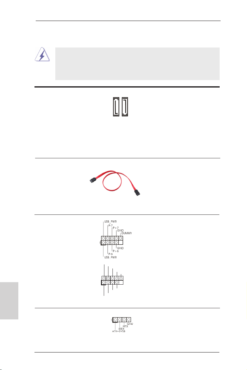
1.4 Колодкииразъемынаплате
Имеющиеся на плате колодки и разъемы НЕ ЯВЛЯЮТСЯ
контактами для перемычек. НЕ УСТАНАВЛИВАЙТЕ перемычки
на эти колодки и разъемы – это приведет к необратимому
повреждению материнской платы!
Разъемы Serial ATAII два соединителя Serial ATAII
(SATAII_1, см. стр. 2, п. 16)
(SATAII_2, см. стр. 2, п. 8)
устройств хранения с
использованием интерфейсных
кабелей SATAII. В настоящее
время интерфейс SATA
допускает скорость передачи
данных до \ 3,0 Гбит/с.
Информационный Информационный кабель
кабель Serial ATA (SATA) интерфейса SATA / SATAII
(дополнительно)
не является направленным.
Любой из его соединителей может
быть подключен либо к жесткому
диску интерфейса SATAII
либо к материнской плате.
предназначаются для
подключения внутренних
SATAII_1
SATAII_2
Русский
Колодка USB 2.0 Помимо стандартных
(9-контактный USB6_7)
(см. стр. 2, п. 15)
портов USB 2.0 на панели ввода-
вывода, на данной материнской
плате предусмотрено два
разъема USB 2.0. Каждый разъем
USB 2.0 поддерживает два порта
USB 2.0.
(9-контактный USB8_9)
(см. стр. 2, п. 9)
1
USB _PWR
P-9
P-8
USB _PWR
P+8
P+9
GND
GND
DUM MY
Датчик пользовательского инфракрасного модуля Датчик можно использовать для
(4-контактный CIR1)
(см. стр. 2, п. 12)
подключения дистанционный
приемник.
60
ASRock AD2550-ITX Motherboard
Page 61
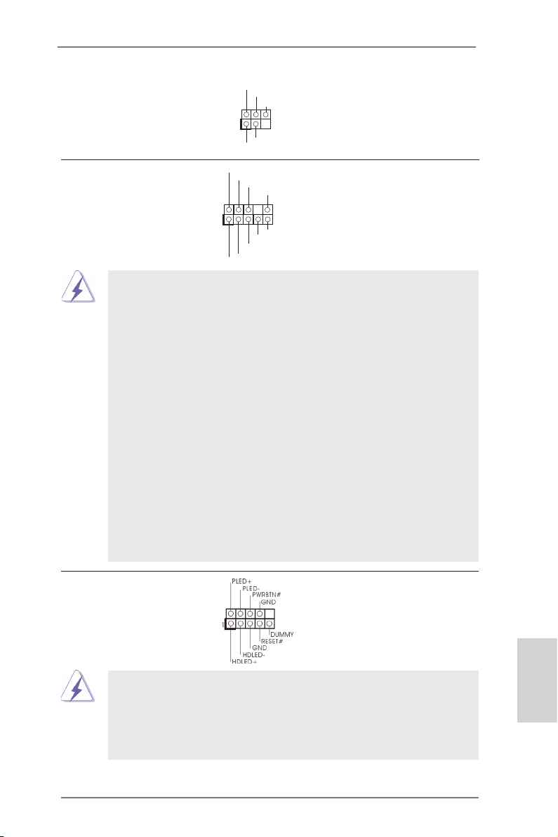
Колодка инфракрасного модуля Данная колодка позволяет
1
IRTX
+5VS B
DUMM Y
IRRX
GND
(5-контактный IR1)
(см. стр. 2, п. 10)
подключить дополнительный
модуль беспроводного
инфракрасного
приемопередатчика.
Аудиоразъем передней Этот интерфейс предназначен
панели для присоединения
(9-контактный HD_AUDIO1)
(см. cтр. 2, п. 19)
обеспечивающего удобное
аудиокабеля передней панели,
подключение аудиоустройств и
управление ими.
1
GND
PRE SENC E#
MIC 2_R
MIC 2_L
MIC _RET
J_S ENSE
OUT 2_R
OUT _RET
OUT 2_L
1. Система High Denition Audio поддерживает функцию
автоматического обнаружения разъемов (Jack Sensing), однако
для ее правильной pаботы кабель панели в корпусе должен
поддерживать HDA. При сборке системы следуйте инструкциям,
приведенным в нашем руководстве и руководстве пользователя
для корпуса.
2. Если вы используете аудиопанель AC’97, подключите ее к колодке
аудиоинтерфейса передней панели следующим образом:
A. Подключите выводы Mic_IN (MIC) к контактам MIC2_L.
B. Подключите выводы Audio_R (RIN) к контактам OUT2_R, а
выводы Audio_L (LIN) к контактам OUT2_L.
C. Подключите выводы Ground (GND) к контактам Ground (GND).
D. Контакты MIC_RET и OUT_RET предназначены только для
аудиопанели HD. При использовании аудиопанели AC’97
подключать их не нужно.
E. Процедура активации микрофона приведена ниже.
Перейдите к вкладке «FrontMic» (Передний микрофон) в панели
управления Realtek. Отрегулируйте уровень «Recording
Volume» (Громкость записи).
Колодка системной панели Данная колодка обеспечивает
(9-контактный PANEL1)
(см. стр. 2, п. 11)
работу нескольких функций
передней панели системы.
Подключите к этому разъему кнопку питания, кнопку сброса
и индикатор состояния системы на корпусе в соответствии с
указанным ниже назначением контактов. При подключении кабелей
Русский
необходимо соблюдать полярность положительных и отрицательных
контактов.
ASRock AD2550-ITX Motherboard
61
Page 62
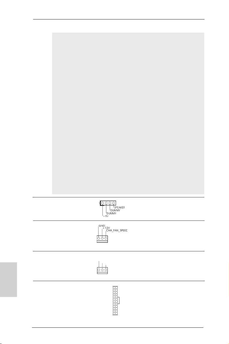
PWRBTN(кнопкапитания):
Подключите к этим контактам кнопку питания на передней панели
корпуса. Способ выключения системы с помощью кнопки питания
можно настроить.
RESET(кнопкасброса):
Подключите к этим контактам кнопку сброса на передней панели
корпуса. Нажмите кнопку сброса для перезагрузки компьютера,
если компьютер «завис» и нормальную перезагрузку выполнить не
удается.
PLED(индикаторпитаниясистемы):
Подключите к этим контактам индикатор состояния питания на
передней панели корпуса. Этот индикатор светится, когда система
работает. Индикатор мигает, когда система находится в режиме
ожидания S1. Этот индикатор не светится, когда система находится
в режиме ожидания S3 или S4, либо выключена (S5).
HDLED(индикаторактивностижесткогодиска):
Подключите к этим контактам индикатор активности жесткого диска
на передней панели корпуса. Этот индикатор светится, когда
осуществляется считывание или запись данных на жестком диске.
Конструкция передней панели может различаться в зависимости от
корпуса. Модуль передней панели в основном состоит из кнопки
питания, кнопки сброса, индикатора питания, индикатора активности
жесткого диска, динамика и т.п. При подключении к этому разъему
модуля передней панели корпуса удостоверьтесь, что провода
подключаются к соответствующим контактам.
Колодка динамика корпуса Подключите к этой колодке
(4-контактный SPEAKER1)
(см. стр. 2, п. 14)
кабель от динамика на корпусе
компьютера.
Русский
Chassis Fan-соединители
(3-контактный CHA_FAN1)
(см. стр. 2, п. 5)
Подключите кабели вентилятора
к соединителям и присоедините
черный шнур к штырю
заземления.
Разъем вентилятора Подключите к этому разъему
процессора кабель вентилятора процессора
(3-контактный CPU_FAN1)
(см. стр. 2, п. 3)
соответствовал контакту земли.
так, чтобы черный провод
Колодка питания ATX Подключите к этой колодке
(24-контактный ATXPWR1)
(см. стр. 2, п. 7)
кабель питания ATX.
GND
+12 V
CPU _FAN_ SPEE D
12 124
13
62
ASRock AD2550-ITX Motherboard
Page 63
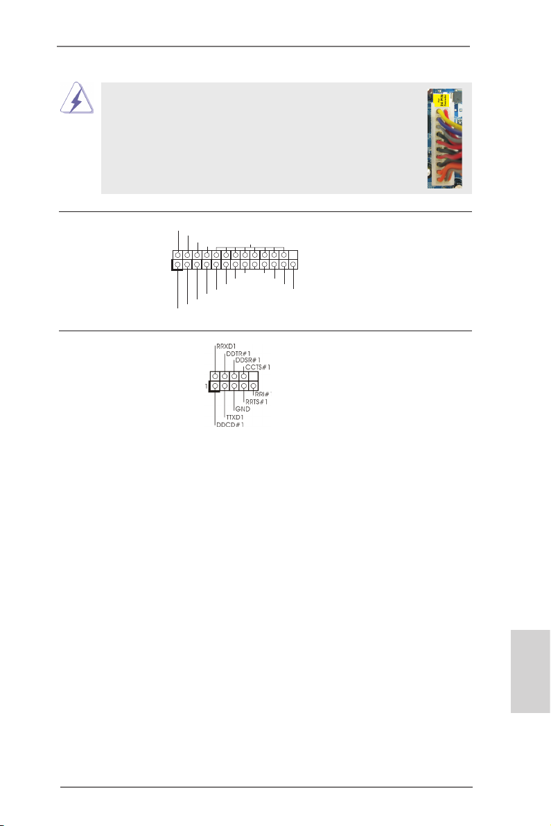
Несмотря на то, что эта материнская плата предусматр ивает 24-штыревой разъем питания ATX, работа будет
продолжаться, даже если адаптируется традиционный
20-штыревой разъем питания ATX. Для использования
20-штыревого разъема питания ATX вставьте источник
питания вместе со штекером 1 и штекером 13.
Установка 20-штыревого разъема питания ATX
12
1
24
13
Разъем порта печати Это интерфейс кабеля порта
(25-выводов LPT1)
(см. стр. 2, п. 1)
подключение принтеров.
AFD #
ERR OR#
печати, обеспечивающий удобное
PIN I T#
SLI N #
1
SPD 2
SPD 1
SPD 0
STB #
SPD 3
SPD 4
SPD 5
SPD 6
GND
SPD 7
ACK #
BUS Y
PE
SLC T
Колодка COM-порта Данная колодка COM-порта
(9-контактный COM1)
(см. стр. 2, п. 2)
позволяет подключить модуль
порта COM.
ASRock AD2550-ITX Motherboard
Русский
63
Page 64

2. ИнформацияоBIOS
Утилита настройки BIOS (BIOS Setup) хранится во флэш-памяти на материнской плате.
Чтобы войти в программу настройки BIOS Setup, при запуске компьютера нажмите <F2>
или <Del> во время самопроверки при включении питания (Power-On-Self-Test – POST).
Если этого не сделать, то процедуры тестирования POST будут продолжаться обычным
образом. Если вы захотите вызвать BIOS Setup уже после POST, перезапустите систему
с помощью клавиш <Ctrl> + <Alt> + <Delete> или нажатия кнопки сброса на корпусе
системы. Подробную информацию о программе BIOS Setup вы найдете в Руководстве
пользователя (в формате PDF) на компакт-диске поддержки.
3. Информацияокомпакт-диске
поддержкиспрограммным
обеспечением
Данная материнская плата поддерживает различные операционные системы Microsoft® Windows®: 7 32-bit. Поставляемый вместе с ней компакт-диск поддержки содержит
необходимые драйверы и полезные утилиты, которые расширяют возможности
материнской платы. Чтобы начать работу с компакт-диском поддержки, вставьте его в
дисковод CD-ROM. Если в вашем компьютере включена функция автозапуска (AUTORUN),
то на экране автоматически появится главное меню компакт-диска (Main Menu). Если этого
не произошло, найдите в папке BIN на компакт-диске поддержки файл ASSETUP.EXE и
дважды щелкните на нем, чтобы открыть меню.
Русский
64
ASRock AD2550-ITX Motherboard
Page 65

1. Introdução
Gratos por comprar nossa placa–mãe AD2550-ITX um produto conável feito com
ASRock um estrito controle de qualidade consistente. Com um excelente desempenho, essa placa é dotada de um projeto robusto que atende a ASRock de compromisso com a qualidade e durabilidade.
Este Guia de Instalação Rápida apresenta a placa-mãe e o guia de instalação passo a passo. Mais informações detalhadas sobre a placa-mãe podem ser encontra-
das no manual do usuário do CD de suporte.
poderiam ser atualizados, o conteúdo deste manual pode ser
cambiado sem aviso. Em caso de qualquer modicação deste
manual, a versão atualizada estará disponível no website de ASRock
sem prévio aviso. Pode também encontrar as listas das mais recentes
placas VGA e das CPUs suportadas no site da web da ASRock.
Website de ASRock http://www.asrock.com
Se precisar de apoio técnico em relação a este placa-mãe, por favor
visite o nosso sítio da internet para informação especíca acerca do
modelo que está a utilizar.
www.asrock.com/support/index.asp
Porque as especicações da placa mãe e o software de BIOS
1.1 Este pacote contém
Placa-mãe ASRock AD2550-ITX
(Formato Mini-ITX: 6,7 pol. x 6,7 pol., 17,0 cm x 17,0 cm)
Guia de instalação rápida da ASRock AD2550-ITX
CD de suporte da placa ASRock AD2550-ITX
Dois cabo de dados ATA Serial (SATA) (Opcional)
Uma proteção I/O
ASRock AD2550-ITX Motherboard
Português
65
Page 66

Português
1.2Especicações
Plataforma - Formato Mini-ITX: 6,7 pol. x 6,7 pol., 17,0 cm x 17,0 cm
- Condensador de design integralmente sólido
CPU - Processador Intel® Dual-Core AtomTM D2550 (1.86 GHz)
- Suporta a tecnologia Hyper-Threading
Chipsets - South Bridge: Intel® NM10 Express
Memória - 2 x slots de DDR3 SO-DIMM
- Suporte para memória não intermédia DDR3 1066/800,
não ECC
- Capacidade máxima de memória do sistema: 4GB
Slots de - 1 slot de PCI
Expansão
VGA integrado - Intel® PowerVR SGX545
- DirectX 9.0, Pixel Shader 3.0
- Três VGA Saída: D-Sub, DVI-D e HDMI portas
- Suporta HDMI 1.3a com resolução máxima até 1920x1200
- Suporta DVI-D com resolução máxima até 1920x1200 @
60Hz
- Suporta D-Sub com resolução máxima até 1920x1200 @
60Hz
- Suportar HDCP função com DVI-D e HDMI portas
- Suportar 1080p Blu-ray (BD) / HD-DVD playback com DVI-D e
HDMI portas
Áudio - Áudio HD de 7.1 canais com protecção de conteúdo
(Codec de áudio Realtek ALC892)
LAN - PCIE x1 Gigabit LAN 10/100/1000 Mb/s
- Realtek RTL8111E
- Suporta Wake-On-LAN
- Suporta Detecção de cabo LAN
- Suporta Ethernet com Eciência Energética 802.3az
- Suporta PXE
Entrada/Saída I/O Panel
pelo painel - 1 x porta para teclado PS/2
traseiro - 1 x porta D-Sub
- 1 x porta DVI-D
- 1 x porta HDMI
- 1 x porta óptica para saída SPDIF
- 4 x portas USB 2.0 padrão
- 2 x portas USB 3.0 padrão (ASMedia ASM1042)
66
ASRock AD2550-ITX Motherboard
Page 67

- 1 x porta LAN RJ-45 com LED (LED ACT/LIG e LED
VELOCIDADE)
- HD Áudio Jack: Altifalante traseiro / Central/Graves /
Entrada de linha / Altifalante frontal / Microfone
Conectores - 2 x conectores SATA2, suporte a taxa de transferência
de dados de até 3,0 Gb/s, suporte NCQ, AHCI e “conexão
a quente”
- 1 x Conector do módulo de infravermelho
- 1 x Conector CIR
- 1 x Conector de Porta de Impressão
- 1 x conector da porta COM
- 1 x Conector do ventilador da CPU (3 pinos)
- 1 x Conector do ventilador da chassis (3 pinos)
- 1 x Conector de força do ATX de 24 pinos
- 1 x Conector Áudio do painel frontal
- 2 x cabezal USB 2.0 (suporta 4 portas USB 2.0)
BIOS - 16Mb BIOS UEFI ocial da AMI com suporte para GUI
- Suporta dispositivos “Plug and Play”
- ACPI 1.1 atendendo a eventos de “wake up”
- Suporta dispositivos sem jumper
- Suporte para SMBIOS 2.3.1
CD de suporte - Controladores, utilitários, software antivírus (Experimentacao
Versao), CyberLink MediaEspresso 6.5 versão de
demonstração, Navegador Google Chrome e Barra de
Ferramentas
Monitor do HW - Sensores de temperature do procesador
- Medição de temperatura da placa-mãe
- Tacômetros de ventilador do Processador
- Tacômetros de ventilador do chassis
- Ventoinha silenciosa para a CPU/chassis
- Monitoramento de voltagem : +12 V, +5 V, +3.3 V, Vcore
Sistema - Microsoft® Windows® 7 de 32 bits
Operacional
Certicações - FCC, CE, WHQL
- “ErP/EuP Ready” (é necessária alimentação eléctrica “ErP/
EuP Ready”)
* Para informações mais detalhadas por favor visite o nosso sítio Web:
http://www.asrock.com
Português
ASRock AD2550-ITX Motherboard
67
Page 68

1.3ConguraçãodosJumpers
A ilustração mostra como os jumpers são
congurados. Quando há uma capa de
jumpers sobre os pinos, diz–se que o jumper está “curto”. Não havendo capa sobre os
pinos, o jumper está “aberto”. A ilustração
mostra um jumper de 3 pinos em que os
pinos 1 e 2 están “curtos” quando a capa
de jumper estiver colocada sobre esses 2
pinos.
Jumper Conguração
Restaurar CMOS
(CLRCMOS1, jumper de 2 pinos)
(veja a folha 2, No. 13)
Nota: CLRCMOS1 permite você limpar os dados em CMOS. Os dados em CMOS
incluem informações da conguração do sistema como: por exemplo a senha
do sistema, data, tempo, e os parámetros da conguração do sistema. Para
limpar e recongurar os parámetros do sistema a conguração inicial da fábrica, por favor desligue o cabo de força, ponha em curto–circuito os pins de
CLRCMOS1 por mais de 5 segundos para limpar o CMOS usando um
jumper.
jumper de 2 pinos
Português
68
ASRock AD2550-ITX Motherboard
Page 69

1.4 Conectores
Os conectores NÃO SÃO jumpers. NÃO coloque capas de jumper
sobre estes conectores. A colocação de pontos de jumper sobre os
conectores causará danos irreversíveis à placa-mãe.
Conector Figura Descrição
Conectores ATAII Serial Estes dois conectores Serial
(SATAII_1: veja a folha 2, No. 16)
(SATAII_2: veja a folha 2, No. 8)
ou SATAII como dispositivos de
armazenamento internos. A
atual interface SATAII permite
uma taxa de transferência de
dados de até 3.0 Gb/s.
Cabo de dados Tanto a saída do cabo de Serial
ATA (SATA) dados SATA pode ser
(opcional)
conectado ao disco rígido
SATA / SATAII quanto o
conector SATAII na placa mãe.
Cabezal USB 2.0 Além das portas USB
(USB6_7 de 9 pinos)
(veja a folha 2, No. 15)
2.0 por defeito no painel de
ligações USB 2.0 nesta placa-
mãe. Cada ligação USB 2.0
pode suportar dois portas USB
(USB8_9 de 9 pinos)
(veja a folha 2, No. 9)
2.0.
ATA (SATAII) suportam
unidades de disco rígido SATA
SATAII_1
SATAII_2
entrada/saída, há dois
USB _PWR
P-9
P+9
GND
DUM MY
1
GND
P+8
P-8
USB _PWR
ASRock AD2550-ITX Motherboard
Português
69
Page 70
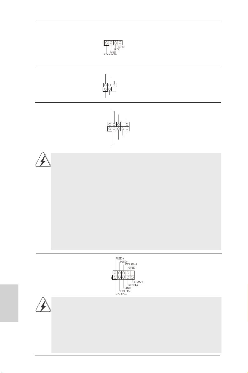
1
IRTX
+5VS B
DUMM Y
IRRX
GND
Conector do módulo de Este conector pode ser utilizado
infravermelhos para ligar o receptor do controlo
(CIR1 de 4 pinos)
(veja a folha 2, No. 12)
remoto.
Conector do módulo Este conector suporta um
de infravermelho módulo de infravermelho para
(IR1 de 5 pinos)
(veja a folha 2, No. 10)
transmissão e recepção sem
o, opcional.
Português
1
GND
PRE SENC E#
MIC 2_R
MIC 2_L
MIC _RET
J_S ENSE
OUT 2_R
OUT _RET
OUT 2_L
Conector Áudio do painel Esta é uma interface para o
frontal cabo de áudio no painel frontal,
(HD_AUDIO1 de 9 pinos)
(veja a folha 2, No. 19)
que permite uma conexão e
controle convenientes dos
dispositivos de áudio.
1. Áudio de elevada denição que suporta a sensibilidade da tomada,
mas o o do painel existente no chassis tem de suportar HDA para
funcionar correctamente. Siga s instruções que aparecem no manual
e no manual do chassis para instalar o sistema.
2. Se utilizar o painel de áudio AC’97, instale-o no cabeçalho de áudio
do painel frontal, como a gura abaixo mostra:
A. Ligue o Mic_IN (MIC) ao MIC2_L.
B. Ligue o Audio_R (RIN) ao OUT2_R e o Audio_L (LIN) ao OUT2_L.
C. Ligue o Ground (GND) ao Ground (GND).
D. MIC_RET e OUT_RET são apenas para o painel de áudio HD. Não
necessita de os ligar para o painel de áudio AC’97.
E. Para activar o microfone frontal.
Aceda ao separador “Microfone frontal” no painel de Controlo
Realtek. Ajuste o “Volume de gravação”.
Conector do painel do sistema Este conector acomoda várias
(PANEL1 de 9 pinos)
(veja a folha 2, No. 11)
funções do painel frontal do
sistema.
Ligue o botão de alimentação, o botão de reposição e o indicador do
estado do sistema no chassis a este conector de acordo com a descrição
abaixo. Tenha em atenção os pinos positivos e negativos antes de ligar os
cabos.
PWRBTN (Botão de alimentação):
70
Ligue ao botão de alimentação no painel frontal do chassis. Pode congu-
rar a forma para desligar o seu sistema através do botão de alimentação.
ASRock AD2550-ITX Motherboard
Page 71

RESET (Botão de reposição):
Ligue ao botão de reposição no painel frontal do chassis. Prima o botão
de reposição para reiniciar o computador caso este bloqueie e não seja
possível reiniciar normalmente.
PLED (LED de alimentação do sistema):
Ligue ao indicador do estado da alimentação no painel frontal do chassis.
O LED cará acesso quando o sistema estiver em funcionamento. O LED
cará intermitente quando o sistema estiver no estado de suspensão S1.
O LED cará desligado quando o sistema estiver nos estados de suspensão S3/S4 ou desligado (S5).
HDLED (LED de actividade do disco rígido):
Ligue ao LED de actividade do disco rígido no painel frontal do chassis. O
LED cará acesso quando o disco rígido estiver a ler ou a escrever dados.
O design do painel frontal poderá variar dependendo do chassis. Um
módulo de painel frontal consiste principalmente em um botão de alimentação, um botão de reposição, um LED de alimentação, um LED de acti-
vidade do disco rígido, um altifalante, etc. Ao ligar o seu módulo de painel
frontal do chassis a este conector, certique-se que os os e os pinos têm
uma correspondência exacta.
Conector do alto-falante do chassi Ligue o alto-falante do chassi
(SPEAKER1 de 4 pinos)
(veja a folha 2, No. 14)
neste conector.
Conector do ventilador do chassis Ligue o cabo do ventilador
(CHA_FAN1 de 3 pinos)
(veja a folha 2, No. 5)
neste conector, coincidindo o o
preto com o pino de aterramen
to.
Conector do ventilador da Ligue o cabo do ventilador da
CPU CPU, coincidindo o o preto
(CPU_FAN1 de 3 pinos)
(veja a folha 2, No. 3)
com o pino de aterramento.
Conector de força do ATX Ligue a fonte de alimentação
(ATXPWR1 de 24 pinos)
(veja a folha 2, No. 7)
ATX neste conector.
GND
+12 V
CPU _FAN_ SPEE D
12 124
13
ASRock AD2550-ITX Motherboard
Português
71
Page 72

Embora esta placa-mãe providencie um conector de
energia ATX de 24 pinos, pode apesar disso funcionar
com a adapta-ção de uma fonte de energia tradicional
de 20 pinos. Para usar a fonte de alimentação de 29
pinos, por favor ligue a sua fonte de alimentação com
o Pino 1 e o Pino 13.
Instalação da Fonte de alimentação ATX de 20 Pinos
12
1
24
13
ERR OR#
PIN I T#
SPD 1
SPD 0
SLI N #
SPD 2
SPD 3
SPD 4
SPD 5
SPD 6
GND
SPD 7
ACK #
BUS Y
Esta é uma interface para um
PE
SLC T
Este conector é usado para
Conector de Porta de Impressão
(LPT1 de 25 pinos)
(veja a folha 2, No. 1)
cabo de porta de impressão
para dispositivos de impressão.
Conector da porta COM
(COM1 de 9 pinos)
(veja a folha 2, No. 2)
AFD #
que permite uma ligação prática
1
STB #
suportar um módulo de porta
COM.
Português
72
ASRock AD2550-ITX Motherboard
Page 73

2. Informações da BIOS
O Utilitário de Conguração do BIOS está armazenado no chip FWH do BIOS. Ao
iniciar o computador, pressione <F2> durante o Autoteste de iniciação (POST) para
acessar o Utilitário de Conguração do BIOS; caso contrário, o POST continuará
com as rotinas de teste. Se desejar acessar o Utilitário de Conguração do BIOS
depois do POST, reinicie o sistema pressionando <Ctl> + <Alt> + <Del>, ou pressio-
nando o botão de reinício no chassi do sistema. Para as informações detalhadas
sobre o Utilitário de Conguração do BIOS, consulte o Manual do Usuário (arquivo
PDF) no CD de suporte.
3. Informações do CD de Suporte
Esta placa Mãe suporta vários sistemas operacionais: Microsoft® Windows®: 7 de
32 bits. O CD de instalação que acompanha a placa Mãe contem: drivers e utilitários necessários para um melhor desempenho da placa Mãe. Para começar a
usar o CD de instalação, introduza o CD na leitora de CD-ROM do computador.
Automaticamente iniciará o menu principal, casa o AUTORUN esteja ativado. Se o
menu principal não aparecer automaticamente, explore o CD e execute o “ASSETUP.
EXE” localizado na pasta BIN.
ASRock AD2550-ITX Motherboard
Português
73
Page 74

1. Giriş
ASRock’ın kesintisiz titiz kalite denetimi altında üretilen güvenilir bir anakart olan
ASRock AD2550-ITX anakartını satın aldığınız için teşekkür ederiz. ASRock’ın kalite ve dayanıklılık konusundaki kararlılığına uygun güçlü tasarımıyla mükemmel bir
performans sunar.
Bu Hızlı Takma Kılavuzu anakarta giriş ve adım adım takma kılavuzu içerir. Anakart
hakkında daha ayrıntılı bilgiyi Destek CD’sinde sunulan kullanıcı kılavuzunda bula-
bilirsiniz.
Anakart özellikleri ve BIOS yazılımı güncelleştirilebileceğinden bu kılavuzun içeriği
önceden haber verilmeksizin değişebilir. Bu belgede değişiklik yapılması durumun
-da, güncelleştirilmiş sürüm ayrıca haber verilmeksizin ASRock web sitesinde
sunulur. En son VGA kartlarını ve CPU destek listelerini de ASRock web sitesinde
bulabilirsiniz. ASRock web sitesi http://www.asrock.com
Bu anakartla ilgili teknik desteğe ihtiyacınız olursa, kullandığınız modele özel bilgiler
için lütfen web sitemizi ziyaret edin.
www.asrock.com/support/index.asp
Türkçe
1.1Paketİçindekiler
ASRock AD2550-ITX Anakart
(Mini-ITX Form Faktörü: 6,7-inç x 6,7-inç, 17,0 cm x 17,0 cm)
ASRock AD2550-ITX Hızlı Takma Kılavuzu
ASRock AD2550-ITX Destek CD’si
2 x Seri ATA (SATA) Veri Kablosu (İsteğe Bağlı)
1 x G/Ç Panel Kalkanı
74
ASRock AD2550-ITX Motherboard
Page 75

1.2 Özellikler
Platform - Mini-ITX Form Faktörü: 6,7-inç x 6,7-inç, 17,0 cm x 17,0 cm
- Tüm Katı Kapasitör tasarımı
CPU - Intel® Çift Çekirdekli AtomTM i şlemcileri destekler D2550
(1.86 GHz)
- Hyper-Threading Teknolojisini destekler
Yonga seti - Southbridge: Intel® NM10 Express
Bellek - 2 x DDR3 SO-DIMM yuva
- DDR3 1066/800 ECC olmayan, ara belleksiz bellek
- Sistem belleğinin maks. kapasitesi: 4 GB
Genişletme - 1 x PCI yuva
Yuvası
Grakler - Intel® PowerVR SGX545
- DirectX 9.0, Pixel Shader 3.0
- Üç VGA Зэkэю seзeneрi: D-Sub, DVI-D ve HDMI
- 1920x1200’e kadar maks. зцzьnьrlьkle HDMI 1.3a
Teknolojisini destekler
- 60Hz’de 1920x1200’e kadar maks. зцzьnьrlьkle DVI-D’yэ
destekler
- 60Hz’de 1920x1200’ya kadar maks. зцzьnьrlьkle D-Sub’э
destekler
- DVI-D ve HDMI portlarэyla HDCP iюlevini destekler
- DVI-D ve HDMI portlarэyla Tam HD 1080p Blu-ray (BD) /
HD-DVD oynatэmэnэ destekler
Ses - İçerik Korumalı (Realtek ALC892 Ses Codec’i) 7,1 Kanal HD
Ses
- Premium Blu-ray ses desteği
LAN - PCIE x1 Gigabit LAN 10/100/1000 Mb/sn
- Realtek RTL8111E
- LAN’da Uyan özelliğini destekler
- LAN Kablo Algılama’yı destekler
- Enerji Verimli Ethernet 802.3az desteği
- PXE’yi destekler
Arka Panel G/З Paneli
G/З - 1 x PS/2 Klavye Portu
- 1 x D-Sub Portu
- 1 x DVI-D Portu
- 1 x HDMI Portu
- 1 x Optik SPDIF Зэkэюэ Portu
- 4 x Kullanэma Hazэr USB 2.0 Portu
Türkçe
ASRock AD2550-ITX Motherboard
75
Page 76

Türkçe
- 2 x Kullanэma Hazэr USB 3.0 Portu (ASMedia ASM1042)
- 1 x RJ-45 LAN Portu, LED’li (AKT/LЭNK LED’i ve HIZ LED’i)
- HD Ses Jakı: Arka Hoparlör/Orta/Bas/Hat Girişi/Ön Hoparlör/
Mikrofon
Konektör - 2 x SATA2 3,0Gb/sn, donanım NCQ, AHCI ve “Sistem Açıkken
Bileşen Takma” işlevlerini
- 1 x KÖ şi
- 1 x Kullanıcı Kızılötesi Modül Bağlantısı
- 1 x Yazdırma Portu Fişi
- 1 x COM portu şi
- 1 x Conector do ventilador da CPU (3 pinos)
- 1 x Conector do ventilador da chassis (3 pinos)
- 1 x 24 pin ATX güç konektörü
- 1 x Ön panel ses konektörü
- 2 x USB 2.0 ş (4 USB 2.0 portu destekler)
BIOSÖzelliği - 16 Mb GUI destekli AMI UEFI Geçerli BIOS
- “Tak Çalıştır”ı destekler
- ACPI 1.1 Uyumlu Uyandırma Olayları
- Jumpersız ayarlamayı destekler
- AMBIOS 2.3.1 Desteği
Destek CD’si - Sürücüler, Yardımcı Programlar, AntiVirüs Yazılımı (Deneme
Sürümü), CyberLink MediaEspresso 6.5 Deneme Sürümü,
Google Chrome Browser ve Toolbar
Donanım - CPU Sıcaklık Duyarlılığı
Monitör - Kasa Sıcaklık Duyarlılığı
- CPU Fan Takometresi
- Kasa Fan Takometresi
- İşlemci/Kasa Sessiz Fanı
- Voltaj İzleme: +12V, +5V, +3,3V, CPU Vcore
İS - Microsoft® Windows® 7 32-bit uyumlu
Sertikalar - FCC, CE, WHQL
- ErP/EuP Hazır (ErP/EuP hazır güç kaynağı gerekli)
* Ayrıntılı ürün bilgileri için lütfen web sitemizi ziyaret edin: http://www.asrock.com
76
ASRock AD2550-ITX Motherboard
Page 77

1.3 Jumper'larınAyarı
Şekilde jumper'ların nasıl ayarlandıkları
gösterilmektedir. Jumper kapağı pinler üzerine
yerleştirildiğinde jumper "Kapalı" dır. Jumper
kapağı pinler üzerindeyken jumper "Açık" tır.
Şekilde pin1 ve pin2'si "Kapalı" olan jumper
kapağı bu 2 pine yerleştirilmiş 3-pinli jumper
gösterilmektedir.
Jumper Ayar
CMOS’u temizleme
(CLRCMOS1, 2-pinli jumper)
(bkz. s.2 No. 13)
Not: CLRCMOS1, CMOS içindeki verileri temizlemenizi sağlar. CMOS’daki
veriler sistem parolası, tarih, saat ve sistem ayar parametreleri gibi sistem
ayar bilgilerini içerir. Sistem parametrelerini temizlemek ve varsayılan
ayarlara sıfırlamak için, lütfen bilgisayarı kapatın ve güç kablosunu güç
kaynağından çıkarın. 15 saniye bekledikten sonra, CLRCMOS1’da 2 pini
kapatmak için 5 saniye kadar bir jumper kapağı kullanın.
2-pinli jumper
ASRock AD2550-ITX Motherboard
Türkçe
77
Page 78

1.4 YerleşikFişlerveKonektörler
Yerleşik şler ve konektörler jumper DEĞİLDİR. Bu şlerin ve konektörlerin üzerine
jumper kapakları YERLEŞTİRMEYİN. Fişlerin ve konektörlerin üzerine jumper
kapakları yerleştirmek anakartın kalıcı olarak zarar görmesine neden olabilir!
Seri ATAII Konektörler Bu iki Seri ATAII (SATAII)
(SATAII_1: bkz. s.2, No. 16)
(SATAII_2: bkz. s.2, No. 8)
SATAII arayüzü 3,0 Gb/sn veri
aktarım hızına izin verir.
Seri ATA (SATA) SATA veri kablosunu her iki ucu
Veri Kablosu da SATA / SATAII sabit
(İsteğe bağlı)
diskine veya anakarttaki
SATAII konektörüne
bağlanabilir.
USB 2.0 Fişleri G/Ç panelindeki varsayılan
(9-pinli USB6_7)
(bkz. s.2 No. 15)
USB 2.0 portundan başka,
bu anakartta iki USB 2.0 şi
bulunur. Her USB 2.0 şi iki
USB 2.0 portunu destekler.
konektör, dahili depolama
cihazları için SATA veri
SATAII_1
kablolarını destekler. Geçerli
SATAII_2
Türkçe
1
USB _PWR
P-9
P-8
USB _PWR
P+9
P+8
GND
GND
DUM MY
(9-pinli USB8_9)
(bkz. s.2 No. 9)
Kullanıcı Kızılötesi Modül Bağlantısı Bu ş, uzaktan kumanda alıcısı
(4-pinli CIR1)
(bkz. s.2 No. 12)
destekler.
78
ASRock AD2550-ITX Motherboard
Page 79
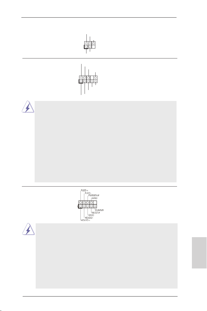
Kızılötesi Modülü Fişi Bu ş, isteğe bağlı bir kablosuz
1
IRTX
+5VS B
DUMM Y
IRRX
GND
(5-pinli IR1)
(bkz. s.2 No. 10)
aktarma ve alma kızılötesi
modülünü destekler.
Ön Panel Ses Fişi Bu, panel ses kablosu için
(9-pinli HD_SES1)
(bkz. s.2 No. 19)
uygun bağlantı sağlayan ve
ses cihazlarını kontrol
etmeyi sağlayan bir arayüzdür.
1
GND
PRE SENC E#
MIC 2_R
MIC 2_L
MIC _RET
J_S ENSE
OUT 2_R
OUT _RET
OUT 2_L
1. Yükse Tanımlı Ses Jak Duyarlılığını destekler, ancak kasadaki panel
kablosunun HDA'nın düzgün çalışmasını desteklemesi gerekir. Lütfen
sisteminizi yüklemek için kılavuzumuzdaki ve kasa kılavuzundaki
talimatları izleyin.
2. AC'97 ses paneli kullanıyorsanız, lütfen ön panel ses şine aşağıdaki gibi
takın:
A. Mic_IN'i (MIC) MIC2_L'ye bağlayın.
B. Audio_R'yi (RIN) OUT2_R'ye ve Audio_L'yi (LIN) OUT2_L'ye bağlayın.
C. Ground'u (GND) Ground'a (GND) bağlayın.
D. MIC_RET ve OUT_RET yalnızca HD ses paneli içindir. Bunları AC’97 ses
paneli için bağlamanız gerekmez.
E. Ön mikrofonu etkinleştirmek için
Realtek Kontrol panelinde “Ön Mikrofon” Sekmesine gidin. “Kayıt Ses
Seviyesi”ni ayarlayın.
Sistem Paneli Fişi Bu ş, birçok sistem ön paneli
(9-pinli PANEL1)
(bkz. s.2 No. 11)
işlevini barındırır.
Kasa üzerindeki güç anahtarını, sıfırlama anahtarını ve sistem durumu
göstergesini aşağıdaki pin atamalarına göre bu bağlantıya bağlayın.
Kabloları bağlamadan önce pozitif ve negatif pinlere dikkat edin.
PWRBTN(GüçAnahtarı):
Kasa üzerindeki güç anahtarını ön panele bağlayın. Güç anahtarını
kullanarak sisteminizi kapatma şeklinizi yapılandırabilirsiniz.
Türkçe
RESET(SıfırlamaAnahtarı):
Kasa üzerindeki sıfırlama anahtarını ön panele bağlayın. Bilgisayar
donarsa veya normal bir yeniden başlatma gerçekleştirilemezse,
bilgisayarı yeniden başlatmak için sıfırlama anahtarına basın.
ASRock AD2550-ITX Motherboard
79
Page 80
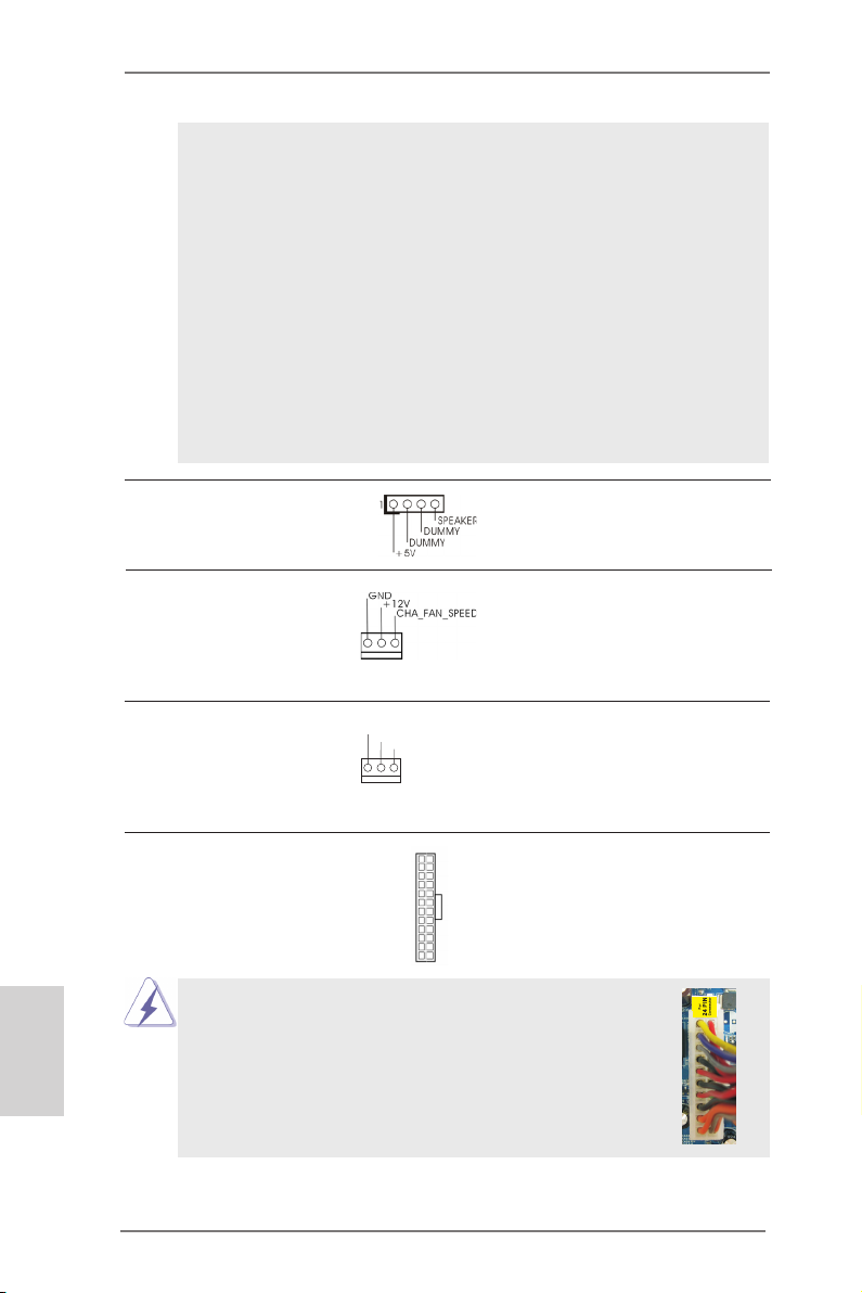
PLED (Sistem Gücü LED’i):
Kasa üzerindeki güç durumu göstergesini ön panele bağlayın. Sistem
çalışırken LED yanar. Sistem S1 uyku modunda iken LED yanıp sön
meye devam eder. Sistem S3/S4 uyku modunda veya kapalı (S5) iken
LED söner.
HDLED(SabitDiskÇalışmaLED’i):
Kasa üzerindeki sabit disk çalışma LED’ini ön panele bağlayın. Sabit
disk veri okurken veya yazarken LED yanar.
Ön panel tasarımı kasaya göre değişiklik gösterebilir. Ön panel
modülünde temel olarak güç anahtarı, sıfırlama anahtarı, güç LED’i,
sabit disk çalışma LED’i, hoparlör vb. bulunur. Kasa ön panel
modülünüzü bu bağlantıya bağlarken, kablo atamalarının ve pin
atamalarının doğru biçimde eşleştirildiğinden emin olun.
Kasa Hoparlörü Fişi Lütfen kasa hoparlörünü bu şe
(4-pinli SPEAKER1)
(bkz. s.2 No. 14)
bağlayın.
Kasa Fan Konektörü Lütfen kasa fan kablolarını
(3-pinli CHA_FAN1)
(bkz. s.2 No. 5)
fanına bu konektöre bağlayın
ve siyah kabloyu toprak pinine
bağlayın.
Türkçe
CPU Fan Konektörü Lütfen fan kablolarını CPU
(3-pinli CPU_FAN1)
(bkz. s.2 No. 3)
fanına bu konektöre bağlayın
ve siyah kabloyu toprak pinine
GND
+12 V
CPU _FAN_ SPEE D
bağlayın.
ATX Güç Konektörü Lütfen bir ATX güç kaynağını
(24-pinli ATXPWR1)
(bkz. s.2 No. 7)
Bu anakart 24-pinli ATX güç konektörü sağlasa da
geleneksel bir 20-pinli ATX güç kaynağı bağlarsanız da
çalışabilir. 20-pinli ATX güç kaynağını kullanmak için,
lütfen güç kaynağınızı Pin 1 ve Pin 13'le birlikte takın.
bu konektöre bağlayın.
12 124
13
20-Pinli ATX Güç Kaynağını Takma
80
ASRock AD2550-ITX Motherboard
12
1
24
13
Page 81

Yazdırma Portu Fişi Bu, yazdırma portu kablosu için
(25-pinli LPT1)
(bkz. s.2 No. 1)
yazıcı cihazlarının uygun
bağlanmasını sağlayan bir
arayüzdür.
1
AFD #
STB #
ERR OR#
PIN I T#
SPD 1
SPD 0
SLI N #
SPD 2
SPD 3
SPD 4
SPD 5
SPD 6
GND
SPD 7
ACK #
BUS Y
PE
SLC T
Seri port Fişi Bu COM1 şi bir seri port
(9-pinli COM1)
(bkz. s.2 No. 2)
modülünü destekler.
ASRock AD2550-ITX Motherboard
Türkçe
81
Page 82

2. BIOS Bilgileri
Anakarttaki Flash Bellek BIOS Ayarları Yardımcı Programını içerir. Bilgisayarı
başlattığınızda, lütfen Otomatik Güç Sınaması (POST) sırasında BIOS Ayarları
yardımcı programına girmek için <F2> veya <Del> tuşuna basın; aksi halde, POST
test rutinlerine devam eder. BIOS Ayarlarına POST'tan sonra girmek istiyorsanız,
lütfen <Ctl> + <Alt> + <Delete> tuşlarına basarak veya sistem kasasındaki sıfırlama
düğmesine basarak sistemi yeniden başlatın. BIOS Ayarları programı kullanıcı
dostu olacak şekilde tasarlanmıştır. Çeşitli alt menüler arasında dolaşmanıza ve
önceden belirlenen seçenekler arasından seçim yapmanıza izin veren menü tabanlı
bir programdır. BIOS Ayarları hakkında ayrıntılı bilgi için, lütfen Destek CD'sinde
bulunan Kullanıcı Kılavuzu'na (PDF dosyası) başvurun.
3. Yazılım Destek CD’si bilgileri
Bu anakart çeşitli Microsoft® Windows® işletim sistemleri destekler: 7 32-bit. Anakartla birlikte gelen Destek CD'si anakart özelliklerini genişleten gerekli sürücüleri
ve kullanışlı yardımcı programları içerir. Destek CD'sini kullanmaya başlamak için,
CD'yi CDROM sürücünüze takın. Bilgisayarınızda "OTOMATİK KULLAN" özelliği
etkinleştirilmişse, Ana Menüyü otomatik olarak görüntüler. Ana Menü otomatik olarak
görüntülenmezse, menüleri görüntülemek için Destek CD'sinin “BIN” klasöründeki
"ASSETUP.EXE" dosyasını bulun ve çift tıklatın.
Türkçe
82
ASRock AD2550-ITX Motherboard
Page 83

1. 제품소개
ASRock 의
메인보드는 엄격한 품질관리 하에 생산되어진 신뢰성 있는 메인보드 입니다 . 이 제품
은 고 품격 디자인과 함께 ASRock 의 우수한 품질과 최고의 안정성을 자랑하고 있습
니다 . 이 빠른 설치 안내서에는 마더보드에 대한 설명과 단계별 설치 방법이 실려 있
습니다 . 마더보드에 대한 보다 자세한 내용은 지원 CD 의 사용 설명서에서 확인할 수
있습니다 .
메인보드의 사양이나 바이오스가 업 데이트 되기 때문에 이 사용자
설명서의 내용은 예고 없이 변경되거나 바뀔 수가 있습니다 . 만일을
생각해서 이 사용자 설명서의 어떤 변경이 있으면 ASRock 의 웹
사이트에서 언제든지 업 데이트를 하실 수 있습니다 . 웹사
이트에서 최신 VGA 카드와 CPU 지원 목록을 확인할 수 있습니다 .
ASRock 의 웹사이트 주소는 http://www.asrock.com 입니다 .
본 머더보드와 관련하여 기술 지원이 필요한 경우 당사 웹 사이트를 방문하
여 사용 중인 모델에 대한 특정 정보를 얻으십시오 .
1.1 패키지 내용
ASRock
(Mini-ITX 폼 팩터 : 6.7” x 6.7”, 17.0 x 17.0 cm)
ASRock
ASRock
시리얼 ATA (SATA) 데이터 케이블 2 개 ( 선택 사양 )
I/O 차폐 1 개
AD2550-ITX
www.asrock.com/support/index.asp
AD2550-ITX
AD2550-ITX
AD2550-ITX
메인 보드를 구매하여 주신것에 대하여 감사 드립니다 . 이
마더보드
퀵 설치 가이드
지원 CD
ASRock AD2550-ITX Motherboard
한 국 어
83
Page 84

한 국 어
1.2 설명서
플랫폼 - Mini-ITX 폼 팩터 : 6.7” x 6.7”, 17.0 x 17.0 cm
- 완전 고체 축전지 디자인
CPU - Intel® Dual-Core AtomTM 프로세서 D2550 (1.86 GHz)
- 하이퍼 - 스레딩 기술 지원
칩셋 - 사우스 브릿지 : Intel® NM10 Express
메모리 - DDR3 SO-DIMM 슬롯 2 개
- DDR3 1066/800 비 -ECC, 언버퍼드 메모리를 지원
- 최대 시스템 메모리 용량 : 4GB
확장 슬롯 - 1 개의 PCI 슬롯
온보드 VGA - Intel
- DirectX 9.0, Pixel Shader 3.0
- 3 개의 VGA 출력 옵션 : D-Sub, DVI-D 및 HDMI
- 최대 해상도 1920x1200 까지 HDMI 1.3a 지원
- 최대 해상도 1920x1200 @ 60Hz 까지 DVI-D 지원
- 최대 해상도 1920x1200 @ 60Hz 까지 D-Sub 지원
- DVI-D 및 HDMI 포트를 이용한 HDCP 기능 지원
- DVI-D 및 HDMI 포트를 이용한 1080p Blu-ray (BD) / HD DVD 재생을 지원
오디오 - 7.1 CH HD Audio 목록 보호 (Realtek ALC892 Audio Codec)
- Premium Blu-ray 오디오 지원
랜 - PCIE x1 Gigabit LAN 10/100/1000 Mb/s
- Realtek RTL8111E
- 웨이크 - 온 - 랜 지원
- LAN 케이블 감지 지원
- 절전형 이더넷 802.3az 지원
- PXE 지원
후면판 I/O I/O Panel
- 1 개 PS/2 키보드 포트
- 1 개의 D-Sub 포트
- 1 개의 DVI-D 포트
- 1 개의 HDMI 포트
- 1 개광학 SPDIF 출력 포트
- 4 개디폴트 USB 2.0 포트
- 2 개디폴트 USB 3.0 포트 (ASMedia ASM1042)
- 1 개 LED(ACT/LINK LED 및 SPEED LED) 가 있는 RJ-45
LAN 포트
- 오디오 잭 : 후방 스피커 / 중앙 / 저음 / 라인 인 / 전방 스피커 /
마이크
®
PowerVR SGX545
84
ASRock AD2550-ITX Motherboard
Page 85

온보드 헤더 - 2 개 의 SATA2 3.0Gb/s 커넥터 , NCQ, AHCI 및“핫 플러그”
및 커넥터 기 능 지원
- 적외선 모듈 헤더 1 개
- 소비자용 적외선 모듈 헤더 1 개
- 프린트 포트 헤더 1 개
- COM 포트 헤더 1 개
- CPU 팬 커넥터 1 개 (3 핀 )
- 섀시 팬 커넥터 1 개 (3 핀 )
- 24 핀 ATX 전원 헤더 1 개
- 전면부 오디오 콘넥터 1 개
- USB 2.0 헤더 2 개 (4 개의 추가 USB 2.0 포트를 지원하는 헤더
2 개 )
BIOS - 16Mb GUI 지원을 제공하는 AMI UEFI 적합형 BIOS
- “플러그 앤 플레이” 지원
- ACPI 1.1 웨이크 - 업 이벤트와의 호환
- 점퍼 프리 지원
- SMBIOS 2.3.1 지원
지원 CD - 드라이버 , 유틸리티 , 백신 소프트웨어 ( 시험판 ), CyberLink
MediaEspresso 6.5 평가판 , Google Chrome Browser 및
Toolbar
하드웨어 모니터 - CPU 온도 감지
- 마더보드 온도 감지
- CPU 과열시 CPU 수명 보호를 위한 시스템 정지기능
- CPU 팬 회전 속도계 : 샤시 ( 케이스 ) 팬 회전 속도계
- CPU/ 마더보드 소음팬
- 전압 감시 기능 : +12V,+5V,+3.3V,Vcore
OS - 마이크로 소프트 Windows® 7 32 비트 와 호환
인증서 - FCC, CE, WHQL
- ErP/EuP 지원 (ErP/EuP 지원 전원 공급기가 요구됨 )
* 상세한 제품정보는 당사의 웹사이트를 방문할수있습니다 . http://www.asrock.com
ASRock AD2550-ITX Motherboard
한 국 어
85
Page 86

1.3 점퍼 셋팅
그림은 점퍼를 어떻게 셋업 하는지를 보여줍니다 .
점퍼 캡이 핀 위에 있을 때 , 점퍼는 “쇼트”입니다 .
점퍼 캡이 핀 위에 없을 때 점퍼는 “오픈” 입니다 .
그림은 3 개의 핀 중 1-2 번 핀이 “쇼트”임을
보여주는 것이며 , 점퍼 캡이 이 두 핀 위에 있음을
보여주는 것입니다 .
점퍼 세팅
CMOS 초기화
(CLRCMOS1,2 핀 점퍼 )
(2 페이지 , 13 번 항목 참조 )
참고 : CLRCMOS1 은 CMOS 에 있는 시스템 설정정보 , 암호 , 날짜 , 시간 그리고
시스템의 설정된 매개 변수 등을 포함하여 모두 지우도록 되어 있습니다 .
바이오스의 초기화 및 기본 셋팅으로 변경을 위해서는 먼저 전원을 끄고
전원 코드를 뽑은 뒤 , CLRCMOS1 단자를 5 초간 쇼트 하십시오 .
2 핀 점퍼
한 국 어
86
ASRock AD2550-ITX Motherboard
Page 87

1.4 온보드 헤더 및 커넥터
주의 !
세요 . 커넥터에 점퍼 캡을 설치하면 마더보드가 영구적으로 손상됩니다 !
콘넥터 그림 설명
시리얼 ATAII 커넥터 2 개의 시리얼 ATAII
(SATAII_1: 2 페이지 , 16 번 항목 참조 )
(SATAII_2: 2 페이지 , 8 번 항목 참조 )
지원합니다 . 커넥터가 내부
기억 장치용 SATA 케이블을
지원합니다 . 현재의 SATAII
인터페이스는 최고 3.0 Gb/s 의
데이터 전송 속도를
지원합니다 .
이 콘넥터는 점퍼가 아닙니다 . 이 콘넥터 위에 점퍼 캡을 사용하지마
(SATA) 커넥터는 내부 저장 장
치용 SATA 데이터 케이블을
SATAII_1
SATAII_2
시리얼 ATA(SATA)
데이터 케이블
( 선택 사양 )
SATA 데이터 케이블의 임의
적인 측을 마더보드의 SATA /
SATAII 하드 디스크
혹은 SATAII 커넥터
에 연결합니다 .
USB 2.0 헤더
(9 핀 USB6_7)
(2 페이지 , 15 번 항목 참조 )
본 머더보드에는 I/O 패널에 있
는 의 기본 USB 2.0 포트
외에도 USB 2.0 헤더가 2 개 있
습니다 . 각각의 USB 2.0 헤더
는 2 개의 USB 2.0 포트를 지원
할 수 있습니다 .
(9 핀 USB8_9)
(2 페이지 , 9 번 항목 참조 )
1
USB _PWR
P-9
P-8
USB _PWR
P+9
P+8
GND
GND
DUM MY
소비자용 적외선 모듈 헤더 이 헤더는 리모콘 수신기
(4 핀 CIR1)
연결하는 데 사용될
(2 페이지 , 12 번 항목 참조 )
수 있습니다 .
한 국 어
ASRock AD2550-ITX Motherboard
87
Page 88

적외선 모듈 헤더 이 헤더는 선택품목인 무선
1
IRTX
+5VS B
DUMM Y
IRRX
GND
(5 핀 IR1)
적외선 송수신 모듈을
(2 페이지 , 10 번 항목 참조 )
지원합니다 .
1
GND
PRE SENC E#
MIC 2_R
MIC 2_L
MIC _RET
J_S ENSE
OUT 2_R
OUT _RET
OUT 2_L
전면부 오디오 콘넥터 이 콘넥터는 오디오 장치를
(9 핀 HD_AUDIO1)
(2 페이지 , 19 번 항목 참조 )
편리하게 조절하고 연결할 수
있는 전면 오디오 인터페이스
입니다 .
1. High Definition Audio( 고음질 오디오 ) 는 잭 센스 기능을 지원하나 , 제
대로작동하려 면 섀시의 패널 와이어가 HAD 를 지원해야 합니다 . 이 설
명서 및 섀시 설명서의지침 을 따라 시스템을 설치하십시오 .
2. AC’97 오디오 패널을 사용하는 경우 , 이를 아래와 같이 프런트 패널
의 오디오헤 더에 설치하십시 오 .
A. Mic_IN (MIC) 을 MIC2_L 에 연결합니다 .
B. Audio_R (RIN) 을 OUT2_R 에 연결하고 , Audio_L (LIN) 을
OUT2_L 에 연결합 니다 .
C. Ground (GND) 을 Ground (GND) 에 연결합니다 .
D. MIC_RET 및 OUT_RET 는 HD 오디오 패널 전용입니다 .
이들을 AC’97 오디오 패널에 연결 하지 않아도 됩니다 .
E. 앞면 마이크 작동 .
Realtek 제어판에서“FrontMic” ( 앞면 마이크 ) 로 가서
“
Recording Volume” ( 리코딩 볼륨 ) 을 조정합니다 .
시스템 콘넥터 이 콘넥터는 시스템 전면 패
(9 핀 PANEL1)
(2 페이지 , 11 번 항목 참조 )
널기능을 지원하기 위한
것입니다 .
한 국 어
섀시의 전원 스위치 , 리셋 스위치 , 시스템 상태 표시등을 아래의 핀 할당
에 따라 이헤더에 연결합니다 . 케이블을 연결하기 전에 양극 핀과 음극 핀
을 기록합니다 .
PWRBTN( 전원 스위치 ):
섀시 전면 패널의 전원 스위치에 연결합니다 . 전원 스위치를 이용해 시스
템을 끄는방법을 구성할 수 있습니다 .
RESET( 리셋 스위치 ):
섀시 전면 패널의 리셋 스위치에 연결합니다 . 컴퓨터가 정지하고 정상적
재시작을수행하지 못할 경우 리셋 스위치를 눌러 컴퓨터를 재시작합니
다 .
88
ASRock AD2550-ITX Motherboard
Page 89

PLED( 시스템 전원 LED):
섀시 전면 패널의 전원 상태 표시등에 연결합니다 . 시스템이 작동하고
있을 때는 LED 가 켜져 있습니다 . 시스템이 S1 대기 상태에 있을 때는
LED 가 계속 깜박입니다 . 시스템이 S3/S4 대기 상태 또는 전원 꺼짐 (S5)
상태에 있을 때는 LED 가 꺼져 있습니다 .
HDLED( 하드 드라이브 동작 LED):
섀시 전면 패널의 하드 드라이브 동작 LED 에 연결합니다 . 하드 드라이
브가 데이터를 읽거나 쓰고 있을 때 LED 가 켜져 있습니다 .
전면 패널 디자인은 섀시별로 다를 수 있습니다 . 전면 패널 모듈은 주로
전원 스위치 , 리셋 스위치 , 전원 LED, 하드 드라이브 동작 LED, 스피커
등으로 구성되어 있습니다 . 섀시 전면 패널 모듈을 이 헤더에 연결할 때
와이어 할당과 핀 할당이 정확히 일치하는지 확인합니다 .
새시 스피커 헤더
(4 핀 SPEAKER 1)
(2 페이지 , 14 번 항목 참조 )
섀시 팬 커넥터
(3 핀 CHA_FAN1)
(2 페이지 , 5 번 항목 참조 )
CPU 팬 커넥터 CPU 팬 케이블을 이 커넥터에
(3 핀 CPU_FAN1)
(2 페이지 , 3 번 항목 참조 )
ATX 전원 헤더
(24 핀 ATXPWR1)
(2 페이지 , 7 번 항목 참조 )
이 마더보드는 24 핀 ATX 전원 커넥터를 제공하지만 ,
새시 스피커를 이 헤더에
연결하십시오 .
팬 케이블을 팬 커넥터에 연결하
고 접지 핀에는 검은색 전선을
연결하십시오 .
GND
+12 V
연결하고 흑색 선을 접지 핀에
CPU _FAN_ SPEE D
맞추십시오 .
12 124
ATX 전원 공급기를 이 헤더에
연결하십시오 .
13
12
24
종래의 20 핀 ATX 전원 공급장치를 사용해도 작동이
가능합니다 . 20 핀 ATX 전원 공급장치를 사용하려면 ,
Pin 1 과 Pin 13 으로 전원공급장치를 연결하십시오 .
20 핀 ATX 전원 공급장치 설치
1
13
한 국 어
ASRock AD2550-ITX Motherboard
89
Page 90

프린트 포트 헤더 이것은 프린터 장치를 편리하
(25 핀 LPT1)
(2 페이지 , 1 번 항목 참조 )
게 연결할 수 있도록 해주는 프
스입니다 .
AFD #
ERR OR#
PIN I T#
SLI N #
린트 포트 케이블용 인터페이
1
SPD 2
SPD 1
SPD 0
STB #
SPD 3
SPD 4
SPD 5
SPD 6
GND
SPD 7
ACK #
BUS Y
PE
SLC T
시리얼포트 컨넥터 이 콘넥터는 시리얼 포트
(9 핀 COM1)
(2 페이지 , 2 번 항목 참조 )
모듈을 지원합니다 .
한 국 어
90
ASRock AD2550-ITX Motherboard
Page 91

2. 시스템 바이오스 정보
메인보드의 플래쉬 메모리에는 바이오스 셋업 유틸리티가 저장되어 있습니다 .
컴퓨터를 사용하실 때 , “자가진단 테스트”(POST) 가 실시되는 동안 <F2> 또는
<Del> 키를 눌러 바이오스 셋업으로 들어가세요 ; 만일 그렇게 하지 않으면 POST
는 테스트 루틴을 계속하여 실행할 것입니다 . 만일 POST 이후 바이오스 셋업을 하
기 원하신다면 ,<Ctl>+<Alt>+<Delete> 키를 누르거나 , 또는 시스템 본체의 리셋
버튼을 눌러 시스템을 재 시작하여 주시기 바랍니다 . 바이오스 셋업 프로그램은 사용
하기 편하도록 디자인되어 있습니다 . 각 항목은 다양한 서브 메뉴 표가 올라오며 미
리 정해진 값 중에서 선택할 수 있도록 되어 있습니다 . 바이오스 셋업에 대한 보다 상
세한 정보를 원하신다면 보조 CD 안의 포함된 사용자 매뉴얼 (PDF 파일 ) 을 따라 주
시기 바랍니다 .
3. 소프트웨어 지원 CD 정보
이 메인보드는 여러 가지 마이크로소프트 윈도우 운영 체계를 지원합니다 :
7 32 비트 . 메인보드에 필요한 드라이버와 사용자 편의를 위해 제공되는 보조 CD 는
메인보드 의 기능을 향상시켜 줄 것입니다 . 보조 CD 를 사용하여 시작하시려면 , CDROM 드라이브에 CD 를 넣어주시기 바랍니다 . 만일 고객님의 컴퓨터가 “AUTORUN” 이 가능하다면 자동으로 메인 메뉴를 모니터에 디스플레이 시켜 줄 것입니다 .
만일 자동으로 메인 메뉴가 나타나지 않는다면 , 보조 CD 의 디스플레이 메뉴 안에 있
는 BIN 폴더 ASSETUP.EXE 파일을 더블 클릭하여 주시기 바랍니다 .
(D: \ BIN \ ASSETUP.EXE, D: 는 CD-ROM 드라이브 )
ASRock AD2550-ITX Motherboard
한 국 어
91
Page 92

1、はじめに
ASRock
品は、弊社の厳しい品質管理の下で製作されたマザーボードです。本製品は、弊社の品
質と耐久性の両立という目標に適合した堅牢な設計により優れた性能を実現します。この
クイックインストレーションガイドには、マザーボードの説明および段階的に説明したインスト
レーションの手引きが含まれています。マザーボードに関するさらに詳しい情報は、「サポー
ト CD」のユーザーマニュアルを参照してください。
マザーボードの仕様および BIOS ソフトウェアは、アップデートされること
が有りますので、マニュアルの内容は、予告なしに変更されることがあり
ます。本マニュアルに変更が有った場合は、弊社のウェブサイトに通告な
しに最新版のマニュアルが掲載されます。最新の VGA カードおよび CPU サ
ポートリストもウェブサイトでご覧になれます。ASRock 社ウェブサイト:
http://www.asrock.com
このマザーボードに関連する技術サポートが必要な場合、当社の Web サイト
にアクセスし、使用しているモデルについての特定情報を見つけてくださ
い。 www.asrock.com/support/index.asp
AD2550-ITX
1.1 パッケージ内容
ASRock
(Mini-ITX フォームファクター : 6.7-in x 6.7-in, 17.0 cm x 17.0 cm)
ASRock
ASRock
2 x シリアル ATA (SATA) データケーブル(オプション)
1 x I/O パネルシールド
AD2550-ITX
AD2550-ITX
AD2550-ITX
マザーボードをお買い上げいただきありがとうございます。本製
マザーボード:
クイックインストレーションガイド
サポート CD
日本語
92
ASRock AD2550-ITX Motherboard
Page 93

1.2 仕様
プラットフ - Mini-ITX フォームファクター :
ォーム 6.7-in x 6.7-in, 17.0 cm x 17.0 cm
- 全ソリッド・キャパシター設計
CPU - Intel® Dual-Core Atom
- ハイパースレッドテクノロジをサポート
ヱップセット - サウスブリッジ : Intel® NM10 Express
メモリー - DDR3 SO-DIMM スロット x 2
- DDR3 1066/800 non-ECC, un-buffered メモリーに対応
- システムメモリの最大容量 : 4GB
拡張スロット - 1 x PCI スロット
グラフィック - Intel® PowerVR SGX545
- DirectX 9.0、Pixel Shader 3.0
- 3 つの VGA 出力オプション :D-Sub、DVI-D、HDMI
- 1920x1200 の最大解像度で HDMI 1.3a をサポート
- 1920x1200 @ 60Hz の最大解像度で DVI-D をサポート
- 1920x1200 @ 60Hz の最大解像度で D-Sub をサポート
- HDCP 機能、DVI-D ポートおよび HDMI ポートをサポート
- 1080p Blu-ray (BD) / HD-DVD 再生サポート、DVI-D ポー
トおよび HDMI ポートをサポート
オーディオ - 7.1 CH HD オーディオ ( コンテンツ保護付 )
(Realtek ALC892 オーディオ Codec)
- Premium Blu-ray オーディオのサポー
LAN - PCIE x1 Gigabit LAN 10/100/1000 Mb/s
- Realtek RTL8111E
- Wake-On-LAN をサポート
- LAN ケーブル検出をサポート
- Energy Efficient Ethernet 802.3az をサポート
- PXE をサポート
リアパネル
I/O - PS/2 キーボードポート x 1
- D-Sub ポート x 1
- DVI-D ポート x 1
- HDMI ポート x 1
- 光学 SPDIF 出力ポート x 1
- Ready-to-Use USB 2.0 ポート x 4
- Ready-to-Use USB 3.0 ポート x 2 (ASMedia ASM1042)
- LED(ACT/LINK LED および SPEED LED)付き RJ-45 LAN
ポート x 1
I/O Panel
TM
プロセッサ D2550 (1.86 GHz)
日本語
ASRock AD2550-ITX Motherboard
93
Page 94
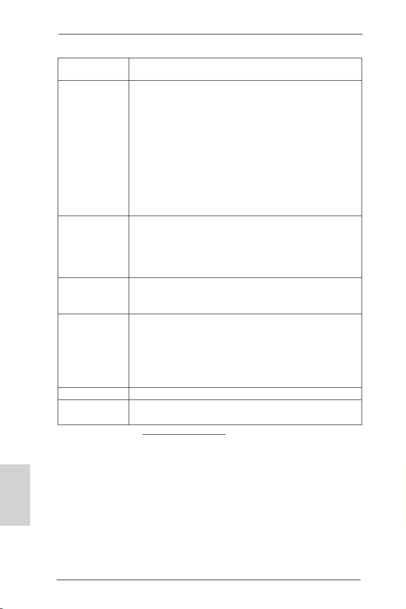
- オーディオジャック: 後部スピーカー、中央低音、入力、前部スピー
カー、マイク入力
コネクター - 2 x SATA2 3.0Gb/ 秒コネクタが、NCQ、AHCI および “Hot
Plug” ( ホットプラグ ) 機能
- IR ヘッダー x 1
- コンシューマー赤外線モジュールヘッダー x 1
- プリントポートヘッダ x 1
- COM ポートヘッダ x 1
- CPU ファンコネクタ x 1 (3 ピン )
- シャーシファンコネクタ x 1 (3 ピン )
- 24 ピン ATX 電源コネクター x 1
- フロントパネルオーディオコネクター x 1
- USB 2.0 ヘッダー (USB 2.0 用 4 ポートをサポート ) x 2
BIOS 関連機能 - 16Mb AMI UEFI Legal BIOS(GUI サポート)
- プラグ&プレイをサポート
- ACPI 1.1 準拠ウェイクアップイベント
- jumperfree モードサポート
- SMBIOS 2.3.1 サポート
サポート CD - ドライバ、ユーティリティ、AntiVirus ソフトウェア ( 試用バー
ジョン )、CyberLink MediaEspresso 6.5 試用版、Google
Chrome Browser および Toolbar
モニター - CPU 温度検知
- マザーボード温度検知
- CPU ファンタコメータ
- シャーシファンタコメータ
- CPU/ マザーボードクワイエットファン
- 電源モニター : +12V, +5V, +3.3V, Vcore
OS - Microsoft® Windows® 7 32-bit compliant
認証 - FCC, CE, Microsoft® WHQL 認証済み
- ErP/EuP 対応(ErP/EuP 対応の電源装置が必要です)
* 製品の詳細については、http://www.asrock.com を御覧なさい。
日本語
94
ASRock AD2550-ITX Motherboard
Page 95

1.3 ジャンパ設定
右の図はジャンパがどのように設定されているかを示しま
す。ジャンパキャップがピンに置かれている場合、ジャンパ
は “ショート” になります。ジャンパキャップがピンに置か
れていない場合、ジャンパ は “オープン”になります。右の
図で、3ピンジャンパで、1-2 ピンを “ショート”の場合、こ
れらの2つのピンにジャンパキャップを置きます。
ジャンパ
クリア CMOS
(CLRCMOS1、2 ピンジャンパ )
ページ2, アイテム 13 を参照
注 : CLRCMOS1 では、CMOS のデータを消去します。CMOS のデータには、システムパ
スワード、日付、時間、システムセットアップパラメータなどのシステムセット
アップ情報が含まれています。システムパラメータをクリアしてデフォルトのセッ
トアップにリセットするには、コンピュータの電源をオフにして電源装置から電源
コードを抜きます。15 秒待ってから、ジャンパキャップを使用して CLRCMOS1 の 2
つのピンを 5 秒間ショートします。
設定 説明
2 ピンジャンパ
ASRock AD2550-ITX Motherboard
日本語
95
Page 96

1.4 オンボードのヘッダとコネクタ類
1
IRTX
+5VS B
DUMM Y
IRRX
GND
オンボードのヘッダとコネクタ類はジャンパではありません。それらのヘッ
ダやコネクタにジャンパキャップをかぶせないでください。ヘッダやコネクタ
にジャンパキャップをかぶせると、マザーボードに深刻な影響を与える場
合があります。
シリアル ATAII コネクタ これら 2 本のシリアル ATAII
SATAII_1: ページ2, アイテム 16 を参照
SATAII_2: ページ2, アイテム 8 を参照
データケーブルに対応していま
す。現在の SATAII インタフェー
スの最大データ転送速度は
3.0 Gb/s です。
レーデバイスに使用する SATA
SATAII_1
(SATAII)コネクタは内蔵スト
SATAII_2
日本語
シリアル ATA(SATA)
データケーブル(オプション)
SATA データケーブルのどちらかの
端をマザーボードの SATA /SATAII
ハードディスク、または SATAII
コネクタに接続できます。
USB 2.0 ヘッダ I/O パネルには、デフォルト
(9 ピン USB6_7)
ページ2, アイテム 15 を参照
の USB 2.0 ポート以外に、この
マザーボードに 2 つの USB 2.0
ヘッダが搭載されています。それ
ぞれの USB 2.0 ヘッダは 2 つの
(9 ピン USB8_9)
ページ2, アイテム 9 を参照
USB 2.0 ポートをサポートできま
す。
1
USB _PWR
P-9
P-8
USB _PWR
P+9
P+8
GND
GND
DUM MY
コンシューマー赤外線モジュールヘッダー このヘッダーは、リモコン受光部
(4 ピン CIR1)
ページ2, アイテム 12 を参照
の接続に使用することができます。
赤外線モジュールコネクタ このコネクタは赤外線の無線送受信
(5 ピン IR1)
ページ2, アイテム 10 を参照
モジュールに対応します。
96
ASRock AD2550-ITX Motherboard
Page 97

1
GND
PRE SENC E#
MIC 2_R
MIC 2_L
MIC _RET
J_S ENSE
OUT 2_R
OUT _RET
OUT 2_L
フロントオーディオパネルコネクタ このコネクタは、オーディオ機器
(9 ピン HD_AUDIO1)
ページ2, アイテム 19 を参照
との便利な接続とコントロールを
可能にするフロンとオーディオパ
ネルのためのインターフェイスで
す。
1. ハイディフィニションオーディオはジャックセンシングをサポー
トしますが、正しく機能するためにシャーシのパネルワイヤが
HAD をサポートする必要があります。このマニュアルとシャー
シのマニュアルの指示に従って、システムを取り付けてくださ
い。
2. AC’97 オーディオパネルを使用する場合、次のように前面パ
ネルのオーディオヘッダに取り付けてください。
A. Mic_IN (MIC) を MIC2_L に接続します。
B. Audio_R (RIN) を OUT2_R に、Audio_L (LIN) を
OUT2_L に接続します。
C. Ground (GND) を Ground (GND) に接続しま
す。
D. MIC_RET と OUT_RET はオーディオパネル専用です。
AC’97 オーディオパネルに接続する必要はありません。
E. フロントマイクを有効化するには。
Realtek コントロールパネルから“FrontMic” ( フロントマイ
ク ) タブを開きます。“Recording Volume”( 録音音量 ) を調
整します。
システムパネルコネクタ このコネクタは数種類のシステム
(9 ピン PANEL1)
ページ2, アイテム 11 を参照
フ ロントパネルの機能を提供しま
す。
シャーシに付いている電源スイッチ、リセットスイッチ、システムステータ
スインジケータを下記のピン割り当て指示に従ってこのヘッダに接続します。
ケーブルを接続する前にピンの正負極性にご注意ください。
PWRBTN ( 電源スイッチ ):
前面パネルに付いている電源スイッチに接続します。電源スイッチによるシス
テム電源オフ方法を設定して変更することも可能です。
RESET ( リセットスイッヱ ):
シャーシの前面パネルに付いているリセットスイッチに接続します。コン
ピュータがフリーズし、正常な再起動をしない場合は、リセットスイッチを
押してコンピュータを再起動します。
ASRock AD2550-ITX Motherboard
日本語
97
Page 98

PLED ( システム電源 LED):
シャーシの前面パネルに付いている電源ステータスインジケータに接続しま
す。LED は、システムが動作しているときに点灯します。LED はシステム
が S1 スリープ状態のときに点滅します。システムが S3 または S4 スリープ状
態になるか、電源オフ (S5) になると、LED は消灯します。
HDLED ( ハードドライブアクティビティ LED):
シャーシの前面パネルに付いているハードドライブアクティビティ LED に接続
します。LED は、ハードドライブがデータの読み込みまたは書き込み動作を
しているときに点灯します。
前面パネルのデザインはシャーシによって異なります。前面パネルモジュール
は、主に電源スイッチ、リセットスイッチ、電源 LED、ハードドライブア
クティビティ LED、スピーカーなどから構成されています。シャーシの前面
パネルモジュールをこのヘッダに接続する際は、ワイヤとピンの割り当てが正
しく対応していることを確認してください。
日本語
シャーシスピーカーヘッダ
(4 ピン SPEAKER1)
ページ2, アイテム 14 を参照
ダを接続してください。
シャーシファンコネクタ
(3 ピン CHA_FAN1)
ページ2, アイテム 5 を参照
CPU ファンコネクタ このコネクタには CPU ファンケー
(3 ピン CPU_FAN1)
ページ2, アイテム 3 を参照
ATX パワーコネクタ ATX 電源コネクタを接続します。
(24 ピン ATXPWR1)
ページ2, アイテム 7 を参照
このマザーボードには 24 ピン ATX 電源コネクタが装備されており、
従来の 20 ピン ATX 電源装置を採用している場合でも作動します。
20 ピン ATX 電源を使用するには、ピン 1 およびピン 13 と共に電源
装置にプラグを差し込みます。
GND
ブルを接続します。黒いコードは
+12 V
CPU _FAN_ SPEE D
アースピンに接続してください。
12 124
13
シャーシのスピーカーとこのヘッ
ファンケーブルをファンコネクタ
に接続し、黒いワイヤをアースピ
ンに合わせてください。
20 ピン ATX 電源装置の取り付け
12
1
24
13
98
ASRock AD2550-ITX Motherboard
Page 99
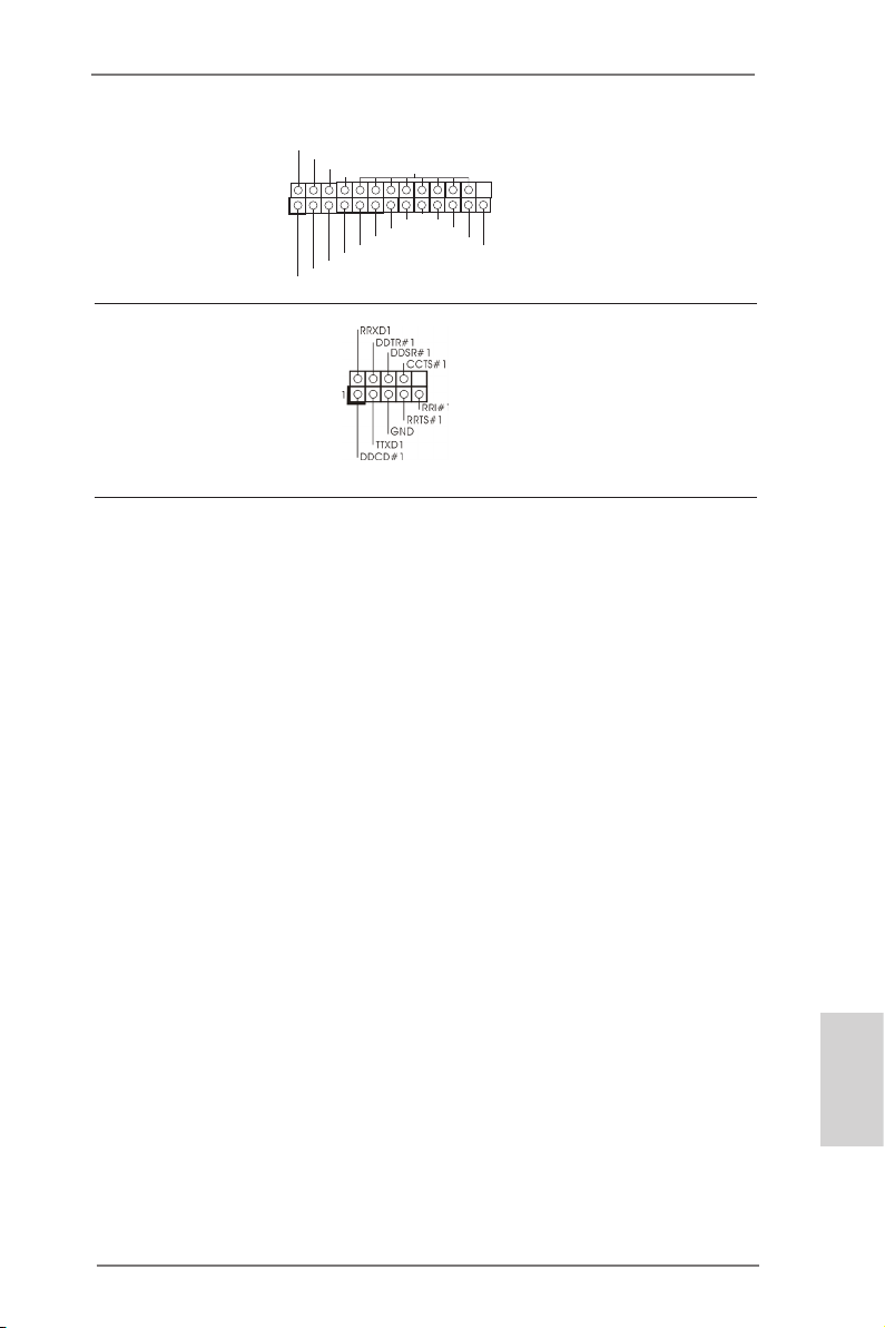
プリントポートヘッダ これはプリントポートケーブル用
(25 ピン LPT1)
ページ2, アイテム 1 を参照
のインターフェイスで、プリンタ
AFD #
ERR OR#
PIN I T#
デバイスの接続を可能にします。
SLI N #
1
SPD 2
SPD 1
SPD 0
STB #
SPD 3
SPD 4
SPD 5
SPD 6
GND
SPD 7
ACK #
BUS Y
PE
SLC T
シリアルポートヘッダ
(9 ピン COM1)
ページ2, アイテム 2 を参照
ジュールをサポートします。
この COM1 ヘッダは、シリアルポートモ
2.BIOS 情報
BIOS セットアップユーティリティはマザーボードのフラッシュメモリに保存されています。コン
ピュータを起動させた後、POST(パワーオンセルフテスト)中に〈F2〉または <Del> を押し、
BIOS セットアップユーティリティに入ってください。押さない場合、POST はテストルーチンを
続けます。テストを実行した後に BIOS セットアップユーティリティに入りたい場合、POST 終
了後〈Ctrl〉+〈Alt〉+〈Delete〉を押すか、ケースのリセットスイッチを押してシステムを
再起動してください。BIOS セットアップユーティリティは、ユーザーフレンドリであることを目
指しています。これはメニュウ方式のプログラムです。スクロールさせることで様々なサブ
メニューを表示し、かつあらかじめ定義した選択肢から選択することが可能です。BIOS セッ
トアップの詳細な情報については、サポート CD 内のユーザーズマニュアル (PDF ファイル )
をごらんください。
3.ソフトウェア サポート CD 情報
このマザーボードは Microsoft® Windows® 7 32-bit といった様々なマイクロソフト ウ
インドウズ オペレーティングシステムをサポートします。マザーボードに付属しているサ
ポート CD はマザーボードの特徴を有効にするために必要なドライバやユーティリティを
含んでいます。サポート CD を使用するには、CDROM ドライブに CD を挿入してください。
AUTORUN 機能が有効な場合、自動的にメインメニュウが立ち上がります。AUTORUN 機
能が無効な場合、サポート CD 内の BIN フォルダにある ASSETUP.EXE をダブルクリック
することにより、メインメニュウが立ち上がります。
日本語
ASRock AD2550-ITX Motherboard
99
Page 100

1. 主板簡介
謝謝你采用了華擎
能夠獲得卓越的性能。本安裝指南介紹了安裝主板的步驟。更加詳細的主板信息可參
看驅動光盤的用戶手冊。
由于主板規格和 BIOS 軟件將不斷升級 , 本手冊之相關內容變更恕不另
行通知。請留意華擎网站上公布的升級版本。你也可以在華擎網站找
到最新的顯卡和 CPU 支持表。
1.1 包裝盒內物品
AD2550-ITX
華擎
(Mini-ITX 規格 : 6.7 英吋 X 6.7 英吋 , 17.0 厘米 X 17.0 厘米 )
AD2550-ITX
華擎
AD2550-ITX
華擎
兩條 Serial ATA(SATA) 數據線 ( 選配 )
一塊 I/O 擋板
AD2550-ITX
華擎网址:http://www.asrock.com
如果您需要與此主板有關的技術支持 , 請參觀我們的網站以了解您使用機
種的規格信息。
www.asrock.com/support/index.asp
主板
快速安裝指南
支持光盤
主板 , 本主板由華擎嚴格制造 , 質量可靠 , 穩定性好 ,
簡體中文
100
ASRock AD2550-ITX Motherboard
 Loading...