

Page 1
Copyright Notice:
No part of this installation guide may be reproduced, transcribed, transmitted, or translated in any language, in any form or by any means, except duplication of documentation
by the purchaser for backup purpose, without written consent of ASRock Inc.
Products and corporate names appearing in this guide may or may not be registered
trademarks or copyrights of their respective companies, and are used only for identication or explanation and to the owners’ benet, without intent to infringe.
Disclaimer:
Specications and information contained in this guide are furnished for informational use
only and subject to change without notice, and should not be constructed as a commitment by ASRock. ASRock assumes no responsibility for any errors or omissions that may
appear in this guide.
With respect to the contents of this guide, ASRock does not provide warranty of any kind,
either expressed or implied, including but not limited to the implied warranties or conditions of merchantability or tness for a particular purpose. In no event shall ASRock, its
directors, ofcers, employees, or agents be liable for any indirect, special, incidental, or
consequential damages (including damages for loss of prots, loss of business, loss of
data, interruption of business and the like), even if ASRock has been advised of the possibility of such damages arising from any defect or error in the guide or product.
This device complies with Part 15 of the FCC Rules. Operation is subject to the following
two conditions:
(1) this device may not cause harmful interference, and
(2) this device must accept any interference received, including interference that
may cause undesired operation.
CALIFORNIA, USA ONLY
The Lithium battery adopted on this motherboard contains Perchlorate, a toxic substance
controlled in Perchlorate Best Management Practices (BMP) regulations passed by the
California Legislature. When you discard the Lithium battery in California, USA, please
follow the related regulations in advance.
“Perchlorate Material-special handling may apply, see
www.dtsc.ca.gov/hazardouswaste/perchlorate”
ASRock Website: http://www.asrock.com
Published June 2011
Copyright©2011 ASRock INC. All rights reserved.
ASRock A75 Pro4-M Motherboard
English
1
Page 2
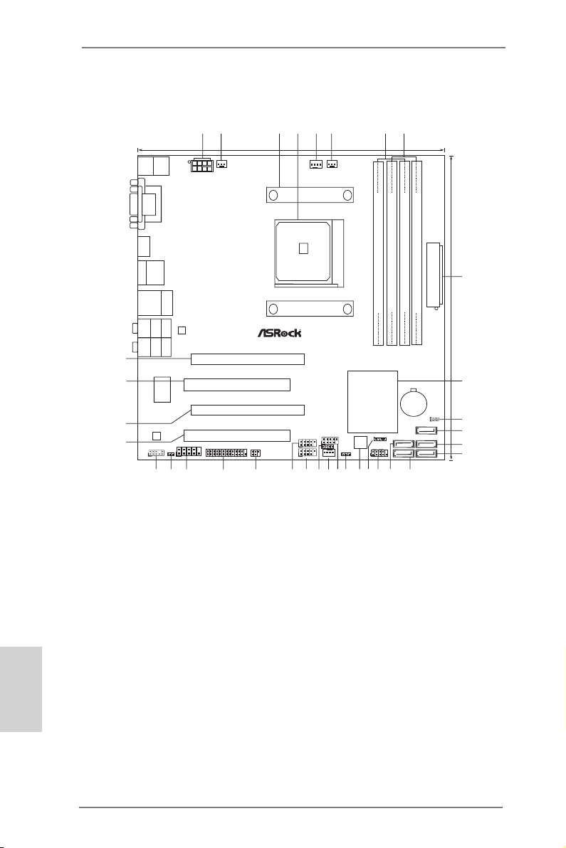
Motherboard Layout
SO CK ET FM 1
A75 Pro 4-M
AMD
A75 FCH
(Hu dso n-D 3 )
Chi pse t
CMOS
BATTE RY
ATXP WR1
DDR3 _A1 (6 4 bit, 240 -pin m odule )
DDR3 _A2 (6 4 bit, 240 -pin m odule )
DDR3 _B1 (6 4 bit, 240 -pin m odule )
DDR3 _B2 (6 4 bit, 240 -pin m odule )
DDR 3 240 0+
32Mb
BIOS
24. 4cm (9 .6-i n)
24. 4cm (9 .6-i n)
Super
I/O
ATX12V1
PWR_FAN1
CPU_FAN1
CPU_FAN2
LAN
AUDIO
CODEC
1
CLRCMOS1
SATA3 6Gb/s
SATA3_1
SATA3_2
SATA3_3
SATA3_4
SATA3_5
HDLED RESE T
PLED PWRBTN
1
PANEL1
CHA_FAN1
SPEAKER1
1
IR1
1
PLED1
1
COM1
1
CIR1
1
1
USB8_9
1
USB10_11
1
USB6_7
HD_AUDIO 1
1
1
HDMI_SPDIF1
1
LPT1
PCIE 1
PCIE 2
PCI 1
PCI 2
HDM I 1. 4a
USB 3.0
DX11
ErP /EuP R eady
RoH S
USB3 .0
T:USB4
B:US B5
Ps2
Keyboa rd/
Mouse
HDMI 1
VGA 1
DVI_ CON1
USB 2.0
T:U SB2
B: USB3
eSATA1
Top:
RJ-45
USB 3.0
T:U SB0
B: USB1
Top:
CTR BASS
Center:
REAR SPK
Bottom:
Optical
SPDIF
Top:
LINE IN
Center:
FRONT
Bottom:
MIC IN
Dua l Gr aphi cs
Gig abit LAN
Des ign ed i n Tai pei
6
7
1
2
4
3
5
8
9
10
11
12
13
14
15
16
17
1819
20
21
22
23
24
25
26
27
28
29
30
31
32
33
34
X
Fast USB
English
1 ATX 12V Power Connector (ATX12V1) 17 System Panel Header (PANEL1, White)
2 Power Fan Connector (PWR_FAN1) 18 Chassis Speaker Header (SPEAKER 1, White)
3 CPU Heatsink Retention Module 19 SPI Flash Memory (32Mb)
4 CPU Socket 20 Power LED Header (PLED1)
5 CPU Fan Connector (CPU_FAN1) 21 USB 2.0 Header (USB6_7, Blue)
6 CPU Fan Connector (CPU_FAN2) 22 Chassis Fan Connector (CHA_FAN1)
7 2 x 240-pin DDR3 DIMM Slots 23 Consumer Infrared Module Header (CIR1)
(Dual Channel A: DDR3_A1, DDR3_B1; Blue) 24 USB 2.0 Header (USB8_9, Blue)
8 2 x 240-pin DDR3 DIMM Slots 25 USB 2.0 Header (USB10_11, Blue)
(Dual Channel B: DDR3_A2, DDR3_B2; White) 26 Infrared Module Header (IR1)
9 ATX Power Connector (ATXPWR1) 27 Print Port Header (LPT1, White)
10 Southbridge Controller 28 COM Port Header (COM1)
11 Clear CMOS Jumper (CLRCMOS1) 29 HDMI_SPDIF Header (HDMI_SPDIF1, White)
12 SATA3 Connector (SATA3_5, White) 30 Front Panel Audio Header (HD_AUDIO1, White)
13 SATA3 Connector (SATA3_4, White) 31 PCI Slot (PCI2)
14 SATA3 Connector (SATA3_3, White) 32 PCI Express 2.0 x16 Slot (PCIE2; Blue)
15 SATA3 Connector (SATA3_1, White) 33 PCI Slot (PCI1)
16 SATA3 Connector (SATA3_2, White) 34 PCI Express 2.0 x16 Slot (PCIE1; Blue)
2
ASRock A75 Pro4-M Motherboard
Page 3
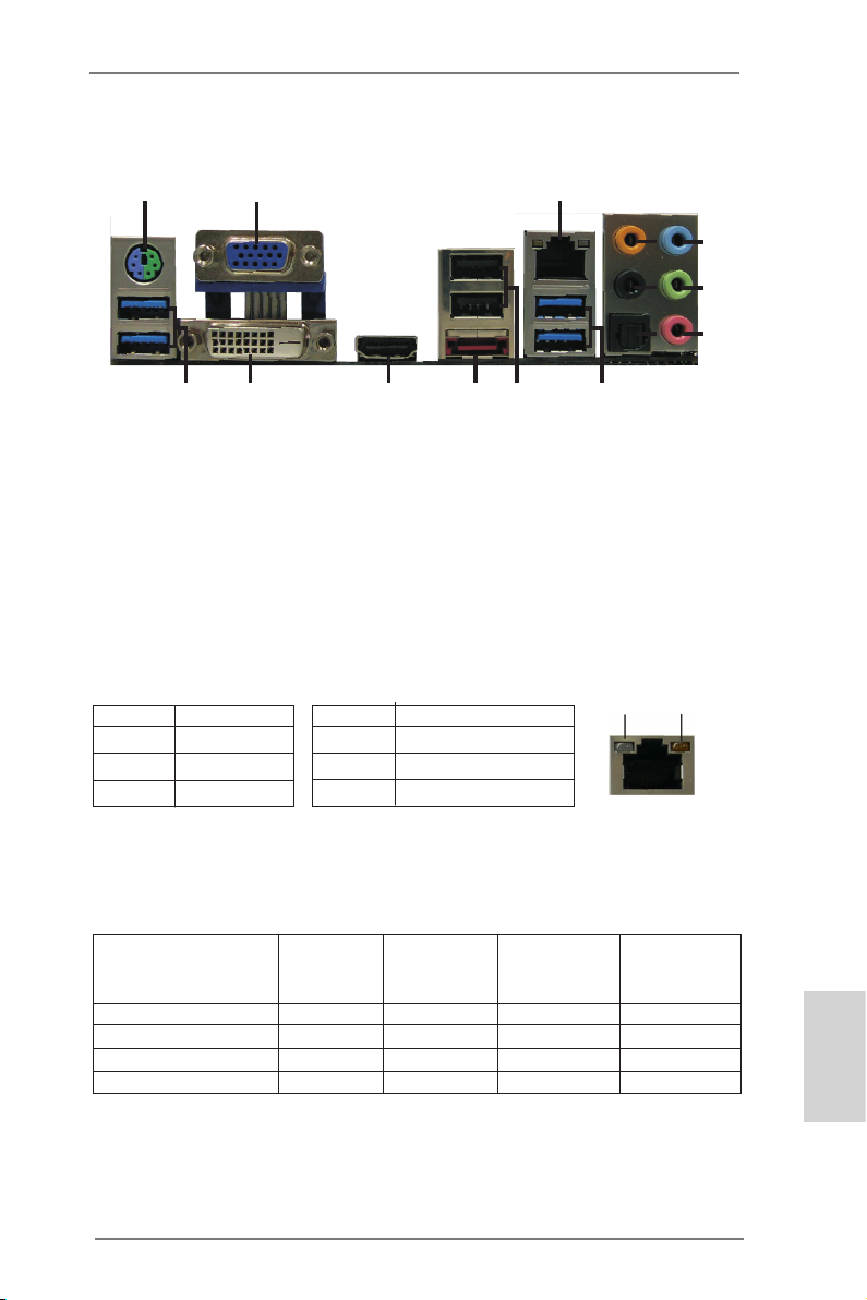
I/O Panel
11
3
10
ACT/LINK
LED
4
5
6
SPEED
LED
7
8
9
1
15
1 PS/2 Mouse/Keyboard Port (Green/Purple) 9 Microphone (Pink)
2 D-Sub Port 10 USB 3.0 Ports (USB01)
* 3 LAN RJ-45 Port *** 11 USB 2.0 Ports (USB23)
4 Central / Bass (Orange) **** 12 eSATA3 Connector
5 Rear Speaker (Black) 13 HDMI Port
6 Optical SPDIF Out Port 14 DVI-D Port
7 Line In (Light Blue) 15 USB 3.0 Ports (USB45)
** 8 Front Speaker (Lime)
* There are two LED next to the LAN port. Please refer to the table below for the LAN port LED
indications.
Activity/Link LED SPEED LED
Status Description Status Description
2
14
LAN Port LED Indications
13
12
Off No Link Off 10Mbps connection
Blinking Data Activity Orange 100Mbps connection
On Link Green 1Gbps connection
LAN Port
If you use 2-channel speaker, please connect the speaker’s plug into “Front Speaker Jack”.
**
See the table below for connection details in accordance with the type of speaker you use.
TABLE for Audio Output Connection
Audio Output Channels Front Speaker Rear Speaker Central / Bass Line In or
(No. 8) (No. 5) (No. 4) Side Speaker
(No. 7)
2 V -- -- -4 V V -- -6 V V V -8 V V V V
ASRock A75 Pro4-M Motherboard
English
3
Page 4
To enable Multi-Streaming function, you need to connect a front panel audio cable to the front
panel audio header. After restarting your computer, you will nd “Mixer” tool on your system.
Please select “Mixer ToolBox” , click “Enable playback multi-streaming”, and click “ok”.
Choose “2CH”, “4CH”, “6CH”, or “8CH” and then you are allowed to select “Realtek HDA Primary output” to use Rear Speaker, Central/Bass, and Front Speaker, or select “Realtek HDA
Audio 2nd output” to use front panel audio.
*** It is recommended to install the USB Keyboard/Mouse cable to USB 2.0 ports (USB23)
instead of USB 3.0 ports.
**** eSATA3 connector supports SATA Gen3 in cable 1M.
English
4
ASRock A75 Pro4-M Motherboard
Page 5
1. Introduction
Thank you for purchasing ASRock A75 Pro4-M motherboard, a reliable motherboard produced under ASRock’s consistently stringent quality control. It delivers
excellent performance with robust design conforming to ASRock’s commitment to
quality and endurance.
This Quick Installation Guide contains introduction of the motherboard and step-bystep installation guide. More detailed information of the motherboard can be found
in the user manual presented in the Support CD.
Because the motherboard specications and the BIOS software might be
updated, the content of this manual will be subject to change without notice. In case any modications of this manual occur, the updated version
will be available on ASRock website without further notice. You may nd
the latest VGA cards and CPU support lists on ASRock website as well.
ASRock website http://www.asrock.com
If you require technical support related to this motherboard, please visit
our website for specic information about the model you are using.
www.asrock.com/support/index.asp
1.1 Package Contents
ASRock A75 Pro4-M Motherboard
(Micro ATX Form Factor: 9.6-in x 9.6-in, 24.4 cm x 24.4 cm)
ASRock A75 Pro4-M Quick Installation Guide
ASRock A75 Pro4-M Support CD
2 x Serial ATA (SATA) Data Cables (Optional)
1 x I/O Panel Shield
ASRock Reminds You...
To get better performance in Windows® 7 / 7 64-bit / Vista
bit, it is recommended to set the BIOS option in Storage Conguration to
AHCI mode. For the BIOS setup, please refer to the “User Manual” in our
support CD for details.
TM
/ VistaTM 64-
ASRock A75 Pro4-M Motherboard
English
5
Page 6
English
1.2 Specifications
Platform - Micro ATX Form Factor: 9.6-in x 9.6-in, 24.4 cm x 24.4 cm
- All Solid Capacitor design
CPU - Support for Socket FM1 100W processors
- V4 + 1 Power Phase Design
- Supports AMD’s Cool ‘n’ QuietTM Technology
- UMI-Link GEN2
Chipset - AMD A75 FCH (Hudson-D3)
Memory - Dual Channel DDR3 Memory Technology (see CAUTION 1)
- 4 x DDR3 DIMM slots
- Support DDR3 2400+(OC)/1866/1600/1333/
1066/800 non-ECC, un-buffered memory (see CAUTION 2)
- Max. capacity of system memory: 32GB (see CAUTION 3)
Expansion Slot - 2 x PCI Express 2.0 x16 slots
(PCIE1 @ x16 mode; PCIE2 @ x4 mode)
- 2 x PCI slots
- Supports AMD Quad CrossFireXTM, CrossFireXTM and Dual
Graphics
Graphics - AMD Radeon HD 65XX/64XX graphics
- DirectX 11, Pixel Shader 5.0
- Max. shared memory 512MB (see CAUTION 4)
- Three VGA Output options: D-Sub, DVI-D and HDMI
(see CAUTION 5)
- Supports HDMI 1.4a Technology with max. resolution up to
1920x1200 @ 60Hz
- Supports Dual-link DVI with max. resolution up to
2560x1600 @ 75Hz
- Supports D-Sub with max. resolution up to 1920x1600 @
60Hz
- Supports Auto Lip Sync, Deep Color (12bpc), xvYCC and
HBR (High Bit Rate Audio) with HDMI (Compliant HDMI
monitor is required) (see CAUTION 6)
- Supports Blu-ray Stereoscopic 3D with HDMI 1.4a
- Supports AMD Steady VideoTM: New video post processing
capability for automatic jutter reduction on home/online
video
- Supports HDCP function with DVI and HDMI ports
- Supports Full HD 1080p Blu-ray (BD) / HD-DVD playback
with DVI and HDMI ports
6
ASRock A75 Pro4-M Motherboard
Page 7
Audio - 7.1 CH HD Audio with Content Protection
(Realtek ALC892 Audio Codec)
- Premium Blu-ray audio support
- Supports THX TruStudio
TM
LAN - PCIE x1 Gigabit LAN 10/100/1000 Mb/s
- Realtek RTL8111E
- Supports Wake-On-LAN
- Supports LAN Cable Detection
- Supports Energy Efcient Ethernet 802.3az
- Supports PXE
Rear Panel I/O I/O Panel
- 1 x PS/2 Mouse/Keyboard Port
- 1 x D-Sub Port
- 1 x DVI-D Port
- 1 x HDMI Port
- 1 x Optical SPDIF Out Port
- 2 x Ready-to-Use USB 2.0 Ports
- 1 x eSATA3 Connector
- 4 x Ready-to-Use USB 3.0 Ports
- 1 x RJ-45 LAN Port with LED (ACT/LINK LED and SPEED
LED)
- HD Audio Jack: Rear Speaker/Central/Bass/Line in/Front
Speaker/Microphone (see CAUTION 7)
SATA3 - 5 x SATA3 6.0 Gb/s connectors, support RAID (RAID 0,
RAID 1 and RAID 10), NCQ, AHCI and “Hot Plug” functions
USB 3.0 - 4 x USB 3.0 ports, support USB 1.0/2.0/3.0 up to 5Gb/s
Connector - 5 x SATA3 6.0Gb/s connectors
- 1 x IR header
- 1 x CIR header
- 1 x Print port header
- 1 x COM port header
- 1 x HDMI_SPDIF header
- 1 x Power LED header
- CPU/Chassis/Power FAN connector
- 24 pin ATX power connector
- 8 pin 12V power connector
- Front panel audio connector
- 3 x USB 2.0 headers (support 6 USB 2.0 ports)
English
ASRock A75 Pro4-M Motherboard
7
Page 8
BIOS Feature - 32Mb AMI UEFI Legal BIOS with GUI support
- Supports “Plug and Play”
- ACPI 1.1 Compliance Wake Up Events
- Supports jumperfree
- SMBIOS 2.3.1 Support
- DRAM, VDDP, VDDR, SB Voltage Multi-adjustment
Support CD - Drivers, Utilities, AntiVirus Software (Trial Version),
CyberLink MediaEspresso 6.5 Trial
Unique Feature - ASRock Extreme Tuning Utility (AXTU) (see CAUTION 8)
- ASRock Instant Boot
- ASRock Instant Flash (see CAUTION 9)
- ASRock APP Charger (see CAUTION 10)
- ASRock XFast USB (see CAUTION 11)
- ASRock On/Off Play Technology (see CAUTION 12)
- Hybrid Booster:
- ASRock U-COP (see CAUTION 13)
Hardware - CPU Temperature Sensing
Monitor - Chassis Temperature Sensing
- CPU/Chassis/Power Fan Tachometer
- CPU/Chassis Quiet Fan
- CPU/Chassis Fan Multi-Speed Control
- Voltage Monitoring: +12V, +5V, +3.3V, Vcore
OS - Microsoft® Windows® 7 / 7 64-bit / Vista
TM
/ VistaTM 64-bit / XP
SP3 / XP 64-bit compliant
Certications - FCC, CE, WHQL
- ErP/EuP Ready (ErP/EuP ready power supply is required)
(see CAUTION 14)
* For detailed product information, please visit our website: http://www.asrock.com
English
WARNING
Please realize that there is a certain risk involved with overclocking, including adjusting the
setting in the BIOS, applying Untied Overclocking Technology, or using the third-party overclocking tools. Overclocking may affect your system stability, or even cause damage to the
components and devices of your system. It should be done at your own risk and expense.
We are not responsible for possible damage caused by overclocking.
8
ASRock A75 Pro4-M Motherboard
Page 9

CAUTION!
1. This motherboard supports Dual Channel Memory Technology. Before
you implement Dual Channel Memory Technology, make sure to read the
installation guide of memory modules on page 14 for proper installation.
2. Whether 2400/1866/1600MHz memory speed is supported depends on
the CPU you adopt. If you want to adopt DDR3 2400/1866/1600 memory
module on this motherboard, please refer to the memory support list on
our website for the compatible memory modules.
ASRock website http://www.asrock.com
3. Due to the operating system limitation, the actual memory size may be
less than 4GB for the reservation for system usage under Windows® 7 /
VistaTM / XP. For Windows® 64-bit OS with 64-bit CPU, there is no such
limitation.
4. The maximum shared memory size is dened by the chipset vendor and
is subject to change. Please check AMD website for the latest information.
5. You can choose to use two of the three monitors only. D-Sub, DVI-D and
HDMI monitors cannot be enabled at the same time. Besides, with the
DVI-to-HDMI adapter, the DVI-D port can support the same features as
HDMIport.
6. xvYCC and Deep Color are only supported under Windows® 7 64-bit /
7. Deep Color mode will be enabled only if the display supports 12bpc
in EDID. HBR is supported under Windows® 7 64-bit / 7 / VistaTM 64-bit /
VistaTM.
7. For microphone input, this motherboard supports both stereo and mono
modes. For audio output, this motherboard supports 2-channel, 4-channel, 6-channel, and 8-channel modes. Please check the table on page 3
for proper connection.
8. ASRock Extreme Tuning Utility (AXTU) is an all-in-one tool to ne-tune
different system functions in a user-friendly interface, which is including
Hardware Monitor, Fan Control, Overclocking, OC DNA and IES. In Hardware Monitor, it shows the major readings of your system. In Fan Control,
it shows the fan speed and temperature for you to adjust. In Overclocking, you are allowed to overclock CPU frequency for optimal system
performance. In OC DNA, you can save your OC settings as a prole
and share with your friends. Your friends then can load the OC prole to
their own system to get the same OC settings. In IES (Intelligent Energy
Saver), the voltage regulator can reduce the number of output phases to
improve efciency when the CPU cores are idle without sacricing computing performance. Please visit our website for the operation procedures
of ASRock Extreme Tuning Utility (AXTU).
ASRock website: http://www.asrock.com
English
ASRock A75 Pro4-M Motherboard
9
Page 10

9. ASRock Instant Flash is a BIOS ash utility embedded in Flash ROM.
This convenient BIOS update tool allows you to update system BIOS
without entering operating systems rst like MS-DOS or Windows®. With
this utility, you can press <F6> key during the POST or press <F2> key to
BIOS setup menu to access ASRock Instant Flash. Just launch this tool
and save the new BIOS le to your USB ash drive, oppy disk or hard
drive, then you can update your BIOS only in a few clicks without preparing an additional oppy diskette or other complicated ash utility. Please
be noted that the USB ash drive or hard drive must use FAT32/16/12 le
system.
10. If you desire a faster, less restricted way of charging your Apple devices,
such as iPhone/iPod/iPad Touch, ASRock has prepared a wonderful solution for you - ASRock APP Charger. Simply installing the APP Charger
driver, it makes your iPhone charged much quickly from your computer
and up to 40% faster than before. ASRock APP Charger allows you to
quickly charge many Apple devices simultaneously and even supports
continuous charging when your PC enters into Standby mode (S1), Suspend to RAM (S3), hibernation mode (S4) or power off (S5). With APP
Charger driver installed, you can easily enjoy the marvelous charging
experience than ever.
ASRock website: http://www.asrock.com/Feature/AppCharger/index.asp
11. ASRock XFast USB can boost USB storage device performance. The
performance may depend on the property of the device.
12. ASRock On/Off Play Technology allows users to enjoy the great audio ex-
perience from the portable audio devices, such like MP3 player or mobile
phone to your PC, even when the PC is turned off (or in ACPI S5 mode)!
This motherboard also provides a free 3.5mm audio cable (optional) that
ensures users the most convenient computing environment.
13. While CPU overheat is detected, the system will automatically shutdown.
Before you resume the system, please check if the CPU fan on the motherboard functions properly and unplug the power cord, then plug it back
again. To improve heat dissipation, remember to spray thermal grease
between the CPU and the heatsink when you install the PC system.
English
10
ASRock A75 Pro4-M Motherboard
Page 11

14. EuP, stands for Energy Using Product, was a provision regulated by European Union to dene the power consumption for the completed system.
According to EuP, the total AC power of the completed system shall be
under 1.00W in off mode condition. To meet EuP standard, an EuP ready
motherboard and an EuP ready power supply are required. According to
Intel’s suggestion, the EuP ready power supply must meet the standard
of 5v standby power efciency is higher than 50% under 100 mA current
consumption. For EuP ready power supply selection, we recommend you
checking with the power supply manufacturer for more details. Besides,
please be noted that if you enable ASRock On/Off Play Technology, your
system will not meet EuP standard. To meet EuP standard, please disable ASRock On/Off Play Technology rst.
ASRock A75 Pro4-M Motherboard
English
11
Page 12
2. Installation
This is a Micro ATX form factor (9.6-in x 9.6-in, 24.4 cm x 24.4 cm) motherboard.
Before you install the motherboard, study the conguration of your chassis to ensure
that the motherboard ts into it.
Pre-installation Precautions
Take note of the following precautions before you install motherboard
components or change any motherboard settings.
Before you install or remove any component, ensure that the
power is switched off or the power cord is detached from the
power supply. Failure to do so may cause severe damage to the
motherboard, peripherals, and/or components.
1. Unplug the power cord from the wall socket before touching any
component.
2. To avoid damaging the motherboard components due to static electricity, NEVER place your motherboard directly on the carpet or the
like. Also remember to use a grounded wrist strap or touch a safety
grounded object before you handle components.
3. Hold components by the edges and do not touch the ICs.
4. Whenever you uninstall any component, place it on a grounded antistatic pad or in the bag that comes with the component.
5. When placing screws into the screw holes to secure the motherboard to the chassis, please do not over-tighten the screws! Doing
so may damage the motherboard.
English
12
ASRock A75 Pro4-M Motherboard
Page 13
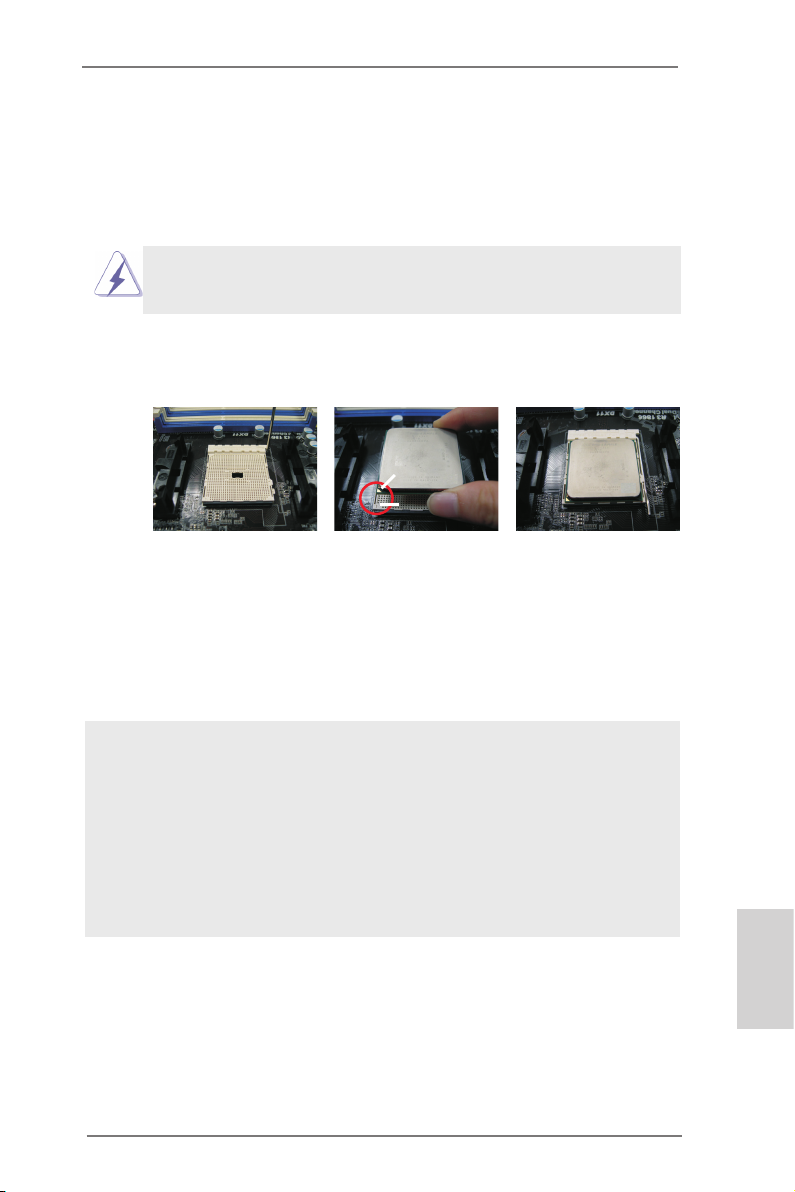
2.1 CPU Installation
Step 1. Unlock the socket by lifting the lever up to a 90
o
angle.
Step 2. Position the CPU directly above the socket such that the CPU corner with
the golden triangle matches the socket corner with a small triangle.
Step 3. Carefully insert the CPU into the socket until it ts in place.
The CPU ts only in one correct orientation. DO NOT force the CPU
into the socket to avoid bending of the pins.
Step 4. When the CPU is in place, press it rmly on the socket while you push
down the socket lever to secure the CPU. The lever clicks on the side tab
to indicate that it is locked.
Lever 90° Up
CPU Golden Triangle
Socket Corner Small
Triangle
STEP 1:
Lift Up The Socket Lever
STEP 2 / STEP 3:
Match The CPU Golden Triangle
To The Socket Corner Small
Triangle
STEP 4:
Push Down And Lock
The Socket Lever
2.2 Installation of CPU Fan and Heatsink
After you install the CPU into this motherboard, it is necessary to install a
larger heatsink and cooling fan to dissipate heat. You also need to spray
thermal grease between the CPU and the heatsink to improve heat dissipation. Make sure that the CPU and the heatsink are securely fastened
and in good contact with each other. Then connect the CPU fan to the
CPU FAN connector (CPU_FAN1, see Page 2, No. 5 or CPU_FAN2, see
Page 2, No. 6). For proper installation, please kindly refer to the instruction manuals of the CPU fan and the heatsink.
English
ASRock A75 Pro4-M Motherboard
13
Page 14
English
2.3 Installation of Memory Modules (DIMM)
This motherboard provides four 240-pin DDR3 (Double Data Rate 3) DIMM
slots, and supports Dual Channel Memory Technology. For dual channel conguration, you always need to install identical (the same brand, speed, size
and chip-type) DDR3 DIMM pair in the slots of the same color. In other words,
you have to install identical DDR3 DIMM pair in Dual Channel A (DDR3_A1
and DDR3_B1; Blue slots; see p.2 No.7) or identical DDR3 DIMM pair in Dual
Channel B (DDR3_A2 and DDR3_B2; White slots; see p.2 No.8), so that Dual
Channel Memory Technology can be activated. This motherboard also allows
you to install four DDR3 DIMMs for dual channel conguration, and please install identical DDR3 DIMMs in all four slots. You may refer to the Dual Channel
Memory Conguration Table below.
Dual Channel Memory Congurations
DDR3_A1 DDR3_A2 DDR3_B1 DDR3_B2
(Blue Slot) (White Slot) (Blue Slot) (White Slot)
(1) Populated - Populated (2) - Populated - Populated
(3)* Populated Populated Populated Populated
For the conguration (3), please install identical DDR3 DIMMs in all four
*
slots.
1. If you want to install two memory modules, for optimal compatibility
and reliability, it is recommended to install them in the slots of the
same color. In other words, install them either in the set of blue
slots (DDR3_A1 and DDR3_B1), or in the set of white slots (DDR3_
A2 and DDR3_B2).
2. If only one memory module or three memory modules are installed
in the DDR3 DIMM slots on this motherboard, it is unable to activate
the Dual Channel Memory Technology.
3. If a pair of memory modules is NOT installed in the same Dual
Channel, for example, installing a pair of memory modules in
DDR3_A1 and DDR3_A2, it is unable to activate the Dual Channel
Memory Technology .
4. It is not allowed to install a DDR or DDR2 memory module into
DDR3 slot; otherwise, this motherboard and DIMM may be damaged.
5. If you adopt DDR3 2400/1866/16 00 memory modul es on this
motherboard, it is recommended to install them on DDR3_A2 and
DDR3_B2 slots.
14
ASRock A75 Pro4-M Motherboard
Page 15
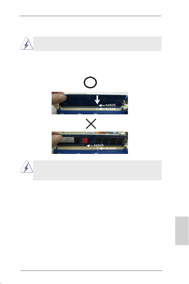
Installing a DIMM
Please make sure to disconnect power supply before adding or
removing DIMMs or the system components.
Step 1. Unlock a DIMM slot by pressing the retaining clips outward.
Step 2. Align a DIMM on the slot such that the notch on the DIMM matches the
break on the slot.
damage to the motherboard and the DIMM if you force the DIMM into
the slot at incorrect orientation.
Step 3. Firmly insert the DIMM into the slot until the retaining clips at both ends
fully snap back in place and the DIMM is properly seated.
The DIMM only ts in one correct orientation. It will cause permanent
ASRock A75 Pro4-M Motherboard
English
15
Page 16
2.4 Expansion Slots (PCI and PCI Express Slots)
There are 2 PCI slots and 2 PCI Express slots on this motherboard.
PCI Slots: PCI slots are used to install expansion cards that have the 32-bit PCI
interface.
PCIE Slots:
PCIE1 (PCIE x16 slot; Blue) is used for PCI Express x16 lane width
graphics cards, or used to install PCI Express graphics cards to support
CrossFireXTM function.
PCIE2 (PCIE x16 slot; Blue) is used for PCI Express x4 lane width
cards, or used to install PCI Express graphics cards to support
CrossFireXTM function.
1. In single VGA card mode, it is recommended to install a PCI Express x16 graphics card on PCIE1 slot.
2. In CrossFireXTM mode, please install PCI Express x16 graphics
cards on PCIE1 and PCIE2 slots.
English
Installing an expansion card
Step 1. Before installing the expansion card, please make sure that the power
supply is switched off or the power cord is unplugged. Please read the
documentation of the expansion card and make necessary hardware
settings for the card before you start the installation.
Step 2. Remove the system unit cover (if your motherboard is already installed
in a chassis).
Step 3. Remove the bracket facing the slot that you intend to use. Keep the
screws for later use.
Step 4. Align the card connector with the slot and press rmly until the card is
completely seated on the slot.
Step 5. Fasten the card to the chassis with screws.
Step 6. Replace the system cover.
16
ASRock A75 Pro4-M Motherboard
Page 17
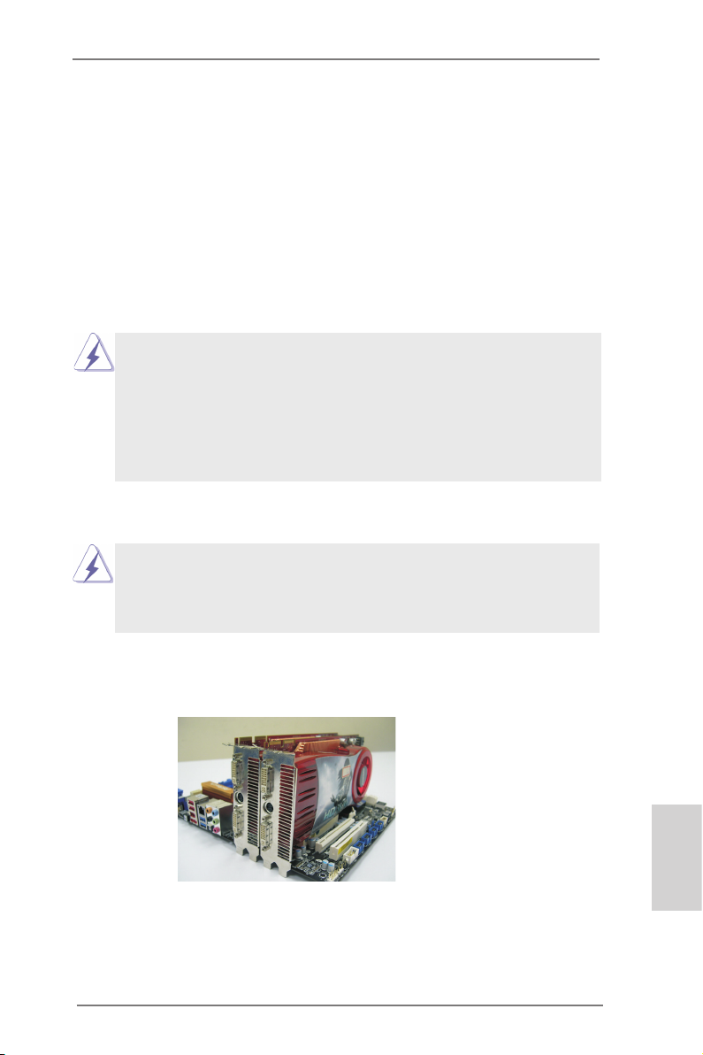
2.5 CrossFireXTM and Quad CrossFireXTM Operation Guide
Th is moth erboard sup ports Cross FireXTM and Qua d Cross FireXTM feature .
CrossFireXTM technology offers the most advantageous means available of
combining multiple high performance Graphics Processing Units (GPU) in a single
PC. Combining a range of different operating modes with intelligent software design
and an innovative interconnect mechanism, CrossFireXTM enables the highest
possible level of performance and image quality in any 3D application. Currently
CrossFireXTM feature is supported with Windows® XP with Service Pack 2 / VistaTM /
7 OS. Quad CrossFireX
TM
feature are supported with Windows® VistaTM / 7 OS only.
Please check AMD website for AMD CrossFireXTM driver updates.
1. If a custome r in correctly con fi gures their sys tem they will not see the
performance benets of CrossFireXTM. All three CrossFireXTM components, a
CrossFireXTM Ready graphics card, a CrossFireXTM Ready motherboard and a
CrossFireXTM Edition co-processor graphics card, must be installed correctly
to benet from the CrossFireXTM multi-GPU platform.
2. If you pair a 12-pipe CrossFireXTM Edition card with a 16-pipe card, both cards
will operate as 12-pipe cards while in CrossFireXTM mode.
2.5.1 Graphics Card Setup
Different CrossFireXTM cards may require different methods to enable CrossFi-
reXTM feature. For other CrossFireXTM cards that AMD has released or will release
in the future, please refer to AMD graphics card manuals for detailed installation
guide.
Step 1. Insert one Radeon graphics card into PCIE1 slot and the other Radeon
graphics card to PCIE2 slot. Make sure that the cards are properly seated
on the slots.
ASRock A75 Pro4-M Motherboard
English
17
Page 18
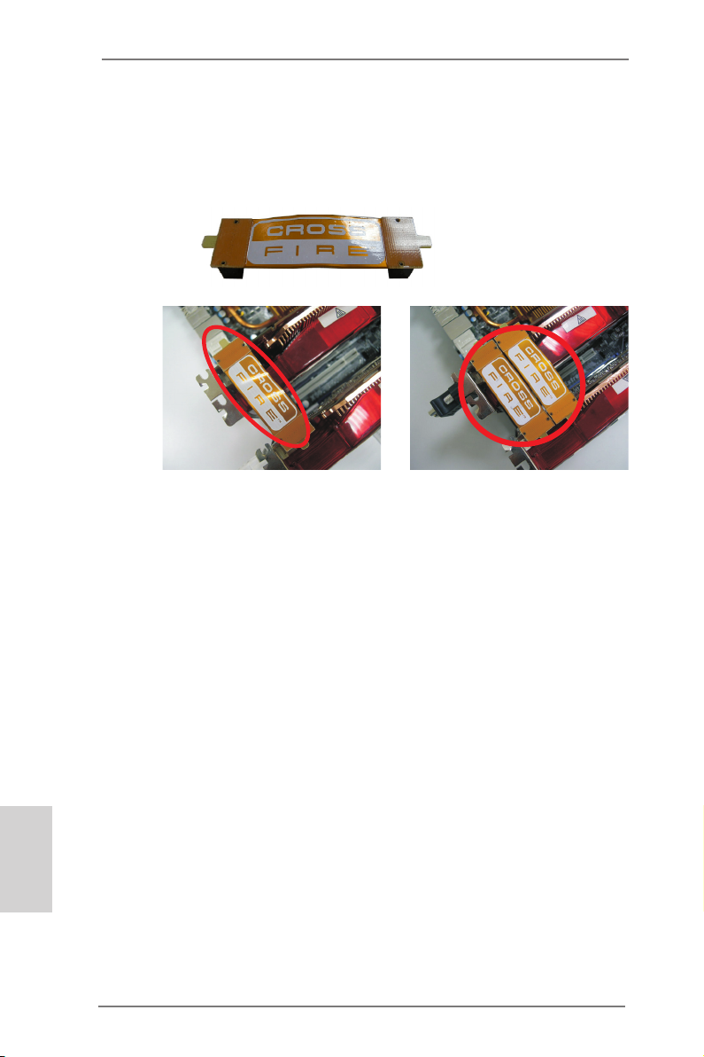
Step 2. Connect two Radeon graphics cards by installing CrossFire Bridge on
CrossFire Bridge Interconnects on the top of Radeon graphics cards.
(CrossFire Bridge is provided with the graphics card you purchase, not
bundled with this motherboard. Please refer to your graphics card vendor
for details.)
CrossFire Bridge
or
Step 3. Connect the DVI monitor cable to the DVI connector on the Radeon graph-
ics card on PCIE1 slot. (You may use the DVI to D-Sub adapter to convert
the DVI connector to D-Sub interface, and then connect the D-Sub monitor
cable to the DVI to D-Sub adapter.)
English
18
ASRock A75 Pro4-M Motherboard
Page 19
2.5.2 Driver Installation and Setup
Step 1. Power on your computer and boot into OS.
Step 2. Remove the AMD driver if you have any VGA driver installed in your sys-
tem.
The Catalyst Uninstaller is an optional download. We recommend using this
utility to uninstall any previously installed Catalyst drivers prior to installation.
Please check AMD website for AMD driver updates.
Step 3. Install the required drivers to your system.
For Windows® XP OS:
A. AMD recommends Windows® XP Service Pack 2 or higher to be
installed (If you have Windows® XP Service Pack 2 or higher installed
in your system, there is no need to download it again):
http://www.microsoft.com/windowsxp/sp2/default.mspx
B. You must have Microsoft .NET Framework installed prior to
downloading and installing the CATALYST Control Center. Please
check Microsoft website for details.
For Windows® 7 / VistaTM OS:
Install the CATALYST Control Center. Please check AMD website for de-
tails.
Step 4. Restart your computer.
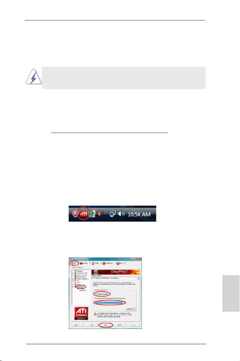
Step 5. Install the VGA card drivers to your system, and restart your computer.
Then you will nd “ATI Catalyst Control Center” on your Windows® taskbar.
ATI Catalyst Control Center
Step 6. Double-click “ATI Catalyst Control Center”. Click “View”, select “CrossFi-
reXTM”, and then check the item “Enable CrossFireXTM”. Select “2 GPUs”
and click “Apply” (if you install two Radeon graphics cards).
ASRock A75 Pro4-M Motherboard
English
19
Page 20
Although you have selected the option “Enable CrossFireTM”, the Cross-
FireXTM function may not work actually. Your computer will automatically
reboot. After restarting your computer, please conrm whether the option
“Enable CrossFireTM” in “ATI Catalyst Control Center” is selected or not;
if not, please select it again, and then you are able to enjoy the benet of
CrossFireX
TM
feature.
Step 7. You can freely enjoy the benet of CrossFireXTM or Quad CrossFireXTM
feature.
* CrossFireXTM appearing here is a registered trademark of AMD Technologies Inc., and is
used only for identication or explanation and to the owners’ benet, without intent to infringe.
* For further information of AMD CrossFireXTM technology, please check AMD website for
updates and details.
English
20
ASRock A75 Pro4-M Motherboard
Page 21
2.6 AMD Dual Graphics Operation Guide
This motherboard supports AMD Dual Graphics feature. AMD Dual Graphics brings
multi-GPU performance capabilities by enabling an AMD A75 FCH (Hudson-D3)
integrated graphics processor and a discrete graphics processor to operate
simultaneously with combined output to a single display for blisteringly-fast frame
rates. Currently, AMD Dual Graphics Technology is only supported with Windows® 7
OS, and is not available with Windows® VistaTM / XP OS.
What does an AMD Dual Graphics system include?
An AMD Dual Graphics system includes an AMD Radeon HD 65XX/64XX graphics
processor and a motherboard based on an AMD A75 FCH (Hudson-D3) integrated
chipset, all operating in a Windows® 7 environment. Please refer to below PCI
Express graphics card support list for AMD Dual Graphics. For the future update of
more compatible PCI Express graphics cards, please visit AMD website for further
information.
Chipset Model Driver
AMD RADEON HD6670 ASUS DIS-PCIE2.1-ASUS-HDMI-EAH6670-DI-1GD3/1G-DDR3 8.86
AMD RADEON HD6570 MSI DIS-PCIE2.1-MSI-HDMI-R6570-MD1GD3-LP/1G-DDR3 8.86
AMD RADEON HD6450 MSI DIS-PCIE2.1-MSI-HDMI-R6450-MD1GD3-LP/1G-DDR3 8.86
Enjoy the benefit of AMD Dual Graphics
Step 1. Please keep the default UEFI setting of “Dual Graphics“ option on [Auto].
Step 2. Install one AMD RADEON HD6670 / 6570 / 6450 PCI Express graphics
card to PCIE1 slot (blue).
Step 3. Connect the monitor cable to the onboard VGA port. Please be noted that
the current VGA driver / VBIOS can allow Dual Graphics output from on-
board display only. For any future update, please refer to our website for
further information.
Step 4. Boot into OS. Please remove the AMD driver if you have any VGA driver
installed in your system.
Step 5. Install the onboard VGA driver from our support CD to your system for
both the onboard VGA and the discrete graphics card.
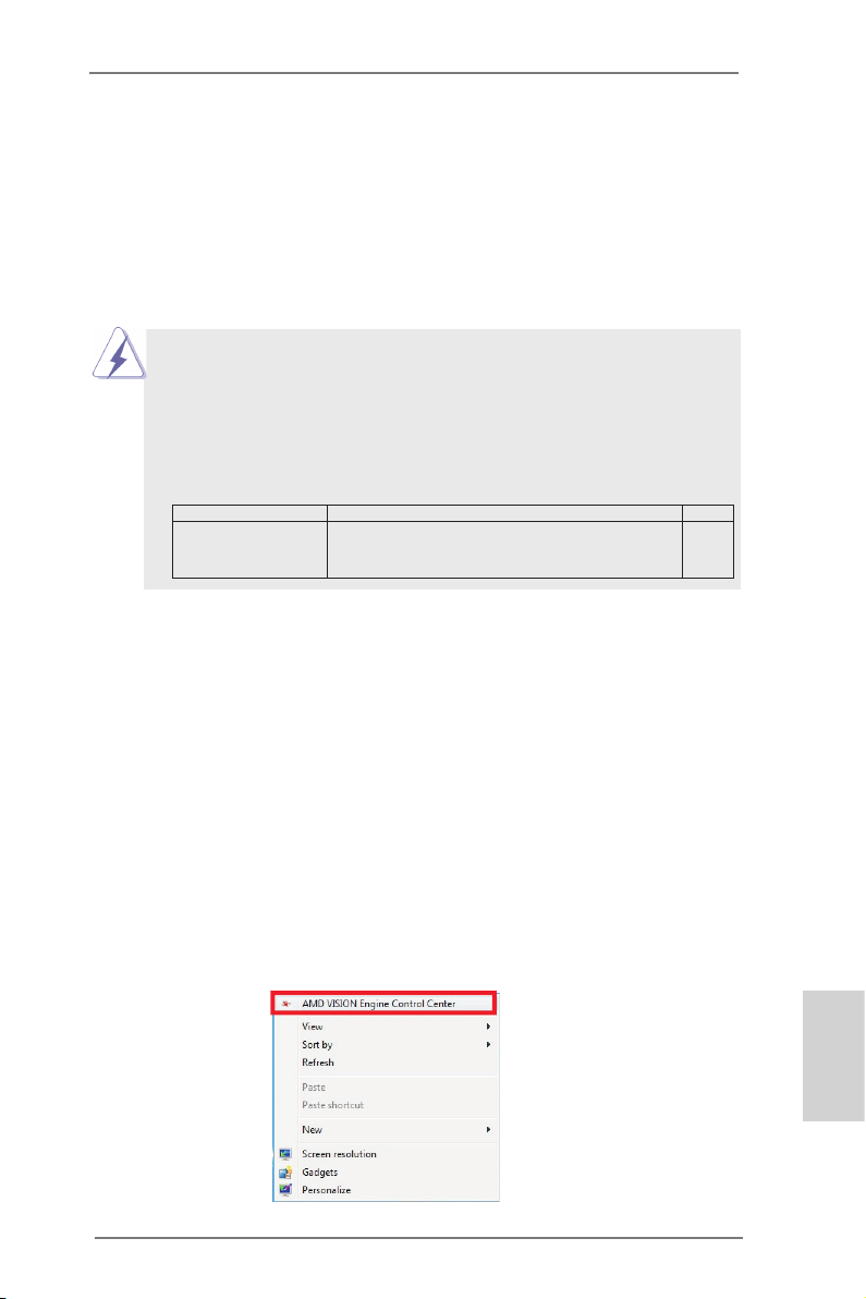
Step 6. Restart your computer. Right-click the desktop. Click “AMD VISION
Engine Control Center” to enter AMD VISION Engine Control Center.
ASRock A75 Pro4-M Motherboard
English
21
Page 22
Step 7. You can also click “AMD VISION Engine Control Center” on your
Windows® taskbar to enter AMD VISION Engine Control Center.
AMD VISION Engine Control Center
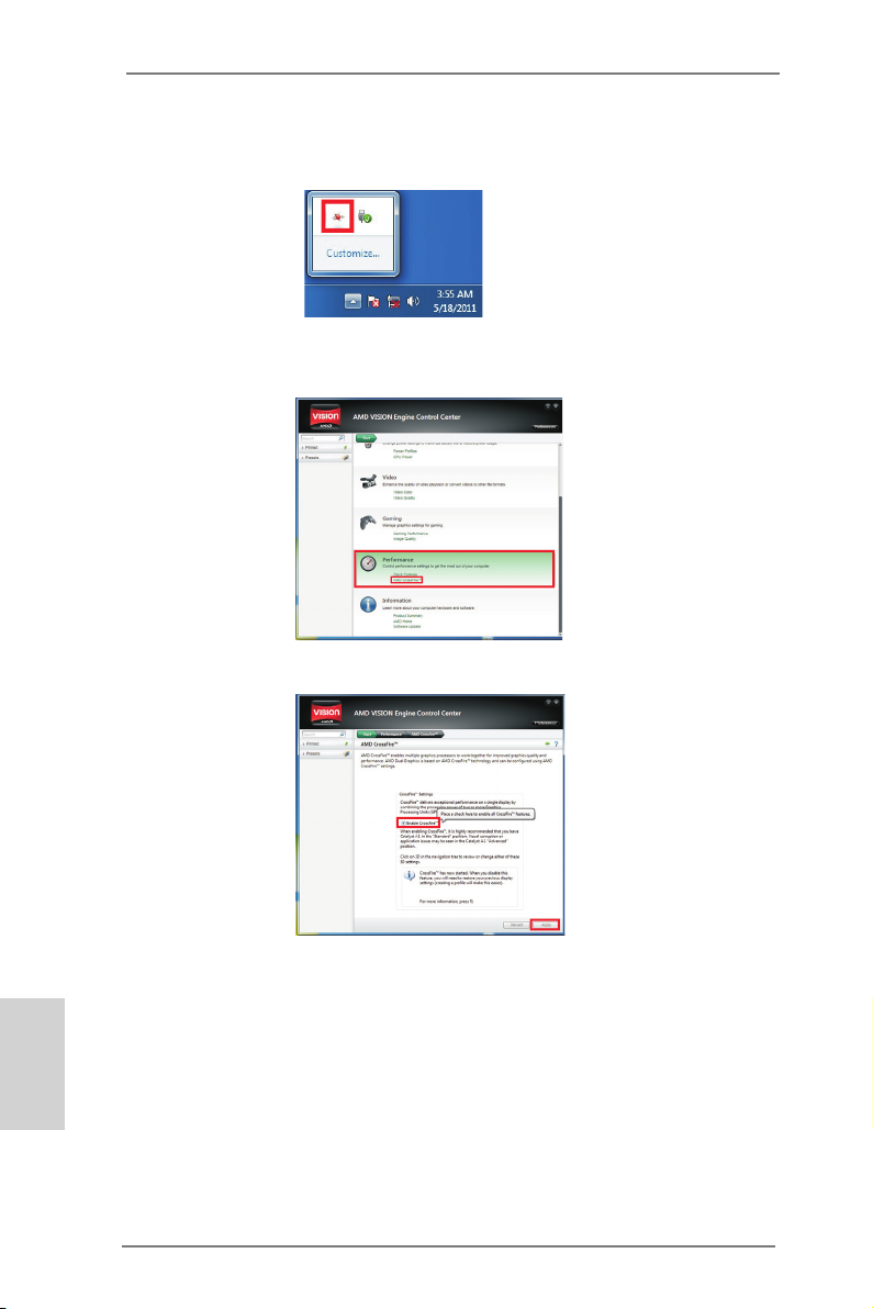
Step 8. In AMD VISION Engine Control Center, please choose “Performance”.
Click “AMD CrossFireTM”.
Step 9. Click “Enable CrossFireTM” and click “Apply“ to save your change.
English
Step 10. Reboot your system. Then you can freely enjoy the benet of Dual
Graphics feature.
* Dual Graphics appearing here is a registered trademark of AMD Technologies Inc., and is
used only for identication or explanation and to the owners’ benet, without intent to infringe.
* For further information of AMD Dual Graphics technology, please check AMD website for up
dates and details.
22
ASRock A75 Pro4-M Motherboard
Page 23
2.7 Dual Monitor and Surround Display Features
Dual Monitor Feature
This motherboard supports dual monitor feature. With the internal VGA output support (DVI-D, D-Sub and HDMI), you can easily enjoy the benets of dual monitor
feature without installing any add-on VGA card to this motherboard. This motherboard also provides independent display controllers for DVI-D, D-Sub and HDMI to
support dual VGA output so that DVI-D, D-sub and HDMI can drive same or different
display contents.
To enable dual monitor feature, please follow the below steps:
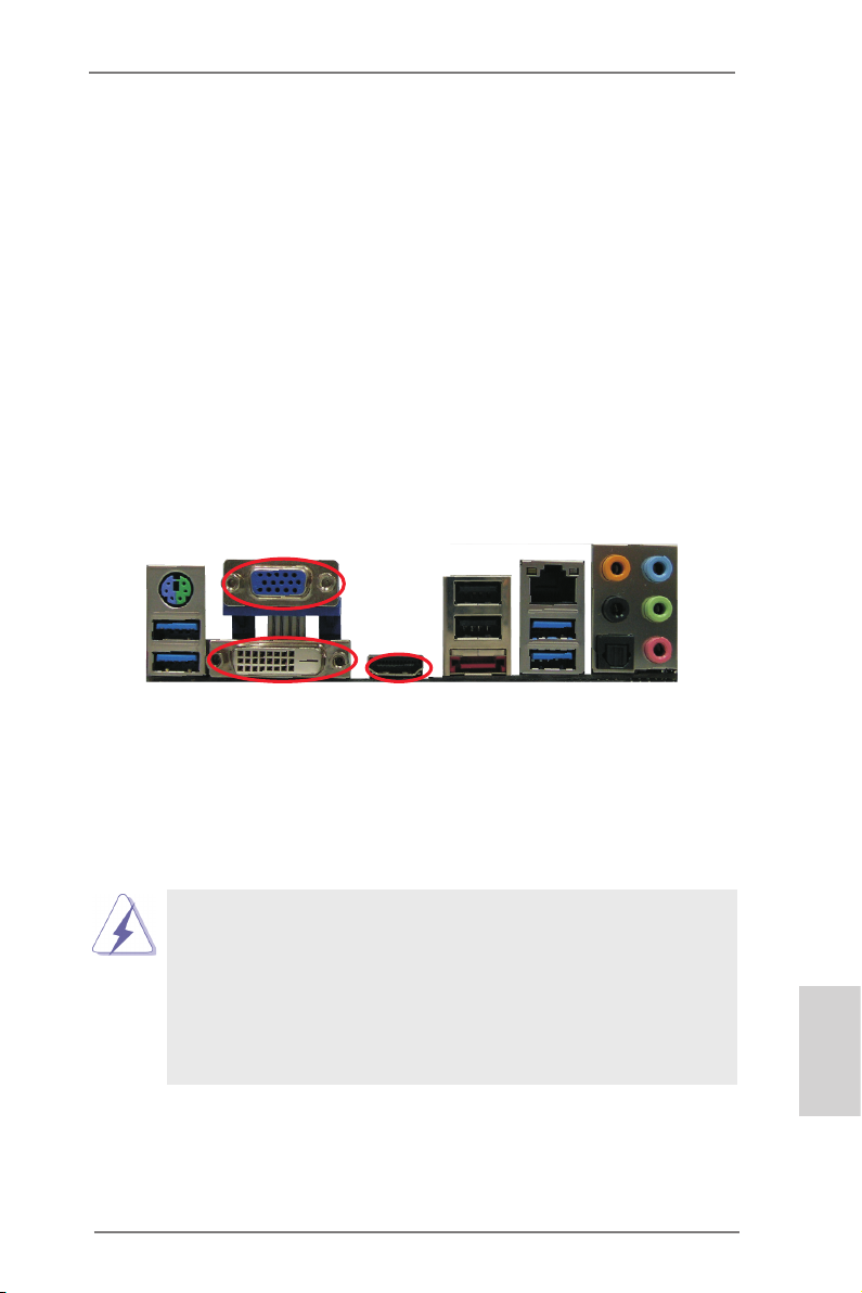
1. Connect DVI-D monitor cable to DVI-D port on the I/O panel, connect D-Sub
monitor cable to D-Sub port on the I/O panel, or connect HDMI monitor cable to
HDMI port on the I/O panel.
D-Sub port
DVI-D port
HDMI port
2. If you have installed onboard VGA driver from our support CD to your system
already, you can freely enjoy the benets of dual monitor function after your
system boots. If you haven’t installed onboard VGA driver yet, please install
onboard VGA driver from our support CD to your system and restart your
computer.
1. D-Sub, DVI-D and HDMI monitors cannot be enabled at the same
time. You can only choose the combination: DVI-D + HDMI, or HDMI
+ D-Sub.
2. When you playback HDCP-protected video from Blu-ray (BD) or
HD-DVD disc, the content will be displayed only in one of the two
monitors instead of both monitors.
3. To support Dual-link DVI monitor, please do not use D-Sub and HDMI
ports. Please connect the DVI monitor cable to the DVI port only.
ASRock A75 Pro4-M Motherboard
English
23
Page 24

Surround Display Feature
This motherboard supports surround display upgrade. With the internal VGA output
support (DVI-D, D-Sub and HDMI) and external add-on PCI Express VGA cards,
you can easily enjoy the benets of surround display feature.
Please refer to the following steps to set up a surround display environment:
1. Install the PCI Express VGA cards on PCIE1 and PCIE2 slots. Please refer to
page 16 for proper expansion card installation procedures for details.
2. Connect DVI-D monitor cable to DVI-D port on the I/O panel, connect D-Sub
monitor cable to D-Sub port on the I/O panel, or connect HDMI monitor
cable to HDMI port on the I/O panel. Then connect other monitor cables to the
corresponding connectors of the add-on PCI Express VGA cards on PCIE1 and
PCIE4 slots.
3. Boot your system. Press <F2> or <Del> to enter UEFI setup. Enter “Share
Memory” option to adjust the memory capability to [32MB], [64MB], [128MB],
[256MB] or [512MB] to enable the function of D-sub. Please make sure that
the value you select is less than the total capability of the system memory. If you
do not adjust the UEFI setup, the default value of “Share Memory”, [Auto], will
disable D-Sub function when the add-on VGA card is inserted to this
motherboard.
4. Install the onboard VGA driver and the add-on PCI Express VGA card driver to
your system. If you have installed the drivers already, there is no need to install
them again.
5. Set up a multi-monitor display.
English
For Windows® XP / XP 64-bit OS:
Right click the desktop, choose “Properties”, and select the “Settings” tab
so that you can adjust the parameters of the multi-monitor according to
the steps below.
A. Click the “Identify” button to display a large number on each monitor.
B. Right-click the display icon in the Display Properties dialog that you
wish to be your primary monitor, and then select “Primary”. When
you use multiple monitors with your card, one monitor will always be
Primary, and all additional monitors will be designated as Secondary.
C. Select the display icon identied by the number 2.
D. Click “Extend my Windows desktop onto this monitor”.
E. Right-click the display icon and select “Attached”, if necessary.
F. Set the “Screen Resolution” and “Color Quality” as appropriate for the
second monitor. Click “Apply” or “OK” to apply these new values.
G. Repeat steps C through E for the diaplay icon identied by the number
one to six.
24
ASRock A75 Pro4-M Motherboard
Page 25
For Windows® 7 / 7 64-bit / VistaTM / VistaTM 64-bit OS:
Right click the desktop, choose “Personalize”, and select the “Display
Settings” tab so that you can adjust the parameters of the multi-monitor
according to the steps below.
A. Click the number ”2” icon.
B. Click the items “This is my main monitor” and “Extend the desktop onto
this monitor”.
C. Click “OK” to save your change.
D. Repeat steps A through C for the display icon identied by the number
three to six.
6. Use Surround Display. Click and drag the display icons to positions representing
the physical setup of your monitors that you would like to use. The placement
of display icons determines how you move items from one monitor to another.
HDCP Function
HDCP function is supported on this motherboard. To use HDCP
function with this motherboard, you need to adopt the monitor
that supports HDCP function as well. Therefore, you can enjoy
the superior display quality with high-denition HDCP
encryption contents. Please refer to below instruction for more
details about HDCP function.
What is HDCP?
HDCP stands for High-Bandwidth Digital Content Protection,
a specication developed by Intel® for protecting digital
entertainment content that uses the DVI interface. HDCP is a
copy protection scheme to eliminate the possibility of
intercepting digital data midstream between the video source,
or transmitter - such as a computer, DVD player or set-top box and the digital display, or receiver - such as a monitor, television
or projector. In other words, HDCP specication is designed to
protect the integrity of content as it is being transmitted.
Products compatible with the HDCP scheme such as DVD
players, satellite and cable HDTV set-top-boxes, as well as few
entertainment PCs requires a secure connection to a compliant
display. Due to the increase in manufacturers employing HDCP
in their equipment, it is highly recommended that the HDTV or
LCD monitor you purchase is compatible.
ASRock A75 Pro4-M Motherboard
English
25
Page 26
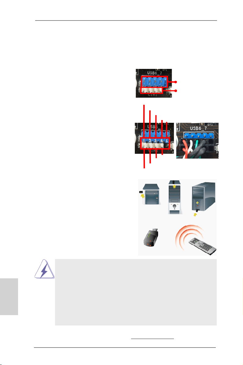
2.8 ASRock Smart Remote Installation Guide
ASRock Smart Remote is only used for ASRock motherboard with CIR header.
Please refer to below procedures for the quick installation and usage of ASRock
Smart Remote.
Step1. Find the CIR header located next
to the USB 2.0 header on ASRock
motherboard.
Step2. Connect the front USB cable to the
USB 2.0 header (as below, pin 1-5)
and the CIR header. Please make
sure the wire assignments and the
pin assignments are matched
correctly.
Step3. Install Multi-Angle CIR Receiver to
the front USB port. If Multi-Angle
CIR Receiver cannot successfully
receive the infrared signals from
MCE Remote Controller, please try
to install it to the other front USB
port.
USB_PWR
ATX+5VSB
P-
IRRX
P+
GND
IRTX
USB 2.0 header
(9-pin, blue)
CIR header
(4-pin, white)
DUMMY
GND
English
3 CIR sensors in different angles
1. Only one of the front USB port can support CIR function. When the
CIR function is enabled, the other port will remain USB function.
2. Multi-Angle CIR Receiver is used for front USB only. Please do not
use the rear USB bracket to connect it on the rear panel. Multi-Angle
CIR Receiver can receive the multi-direction infrared signals (top,
down and front), which is compatible with most of the chassis on the
market.
3. The Multi-Angle CIR Receiver does not support Hot-Plug function.
Please install it before you boot the system.
* ASRock Smart Remote is only supported by some of ASRock motherboards. Please refer to
ASRock website for the motherboard support list: http://www.asrock.com
26
ASRock A75 Pro4-M Motherboard
Page 27
2.9 Jumpers Setup
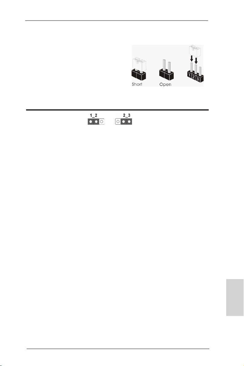
The illustration shows how jumpers are
setup. When the jumper cap is placed on
pins, the jumper is “Short”. If no jumper cap
is placed on pins, the jumper is “Open”. The
illustration shows a 3-pin jumper whose
pin1 and pin2 are “Short” when jumper cap
is placed on these 2 pins.
Jumper Setting Description
Clear CMOS Jumper
(CLRCMOS1)
(see p.2, No. 11)
Note: CLRCMOS1 allows you to clear the data in CMOS. To clear and reset the
system parameters to default setup, please turn off the computer and unplug
the power cord from the power supply. After waiting for 15 seconds, use a
jumper cap to short pin2 and pin3 on CLRCMOS1 for 5 seconds. However,
please do not clear the CMOS right after you update the BIOS. If you need
to clear the CMOS when you just nish updating the BIOS, you must boot
up the system rst, and then shut it down before you do the clear-CMOS action. Please be noted that the password, date, time, user default prole, 1394
GUID and MAC address will be cleared only if the CMOS battery is removed.
Clear CMOSDefault
ASRock A75 Pro4-M Motherboard
English
27
Page 28
2.10 Onboard Headers and Connectors
Onboard headers and connectors are NOT jumpers. Do NOT place
jumper caps over these headers and connectors. Placing jumper caps
over the headers and connectors will cause permanent damage of the
motherboard!
English
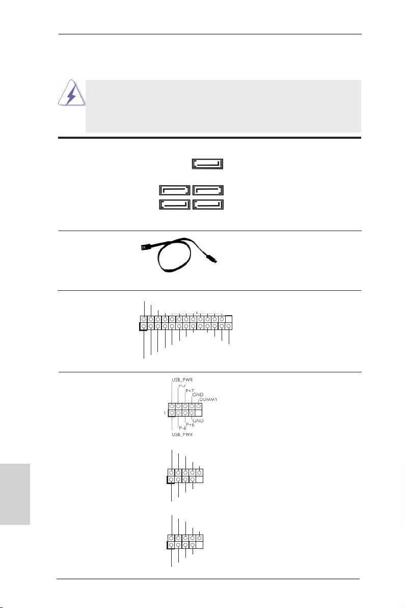
Serial ATA3 Connectors These ve Serial ATA3
(SATA3_1: see p.2, No. 15)
(SATA3_2: see p.2, No. 16)
(SATA3_3: see p.2, No. 14)
(SATA3_4: see p.2, No. 13)
(SATA3_5: see p.2, No. 12)
(SATA3) connectors support
SATA data cables for internal
SATA3_2 SATA3_4
storage devices. The current
SATA3 interface allows up to
6.0 Gb/s data transfer rate.
SATA3_1 SATA3_3
SATA3_5
Serial ATA (SATA) Ei ther end of the SATA data
Data Cable cable can be connected to the
(Optional)
SATA3 hard disk or the SATA3
connector on this motherboard.
1
AFD #
STB #
ERR OR#
PIN I T#
SPD 1
SPD 0
SLI N #
SPD 2
SPD 3
SPD 4
SPD 5
SPD 6
GND
SPD 7
ACK #
BUS Y
PE
SLC T
Print Port Header This is an interface for print
(25-pin LPT1)
(see p.2 No. 27)
port cable that allows
convenient connection of printer
devices.
USB 2.0 Headers Besides two default USB 2.0
(9-pin USB6_7)
(see p.2 No. 21)
ports on the I/O panel, there
are three USB 2.0 headers on
this motherboard. Each USB 2.0
header can support two USB
2.0 ports.
(9-pin USB8_9)
(see p.2 No. 24)
(9-pin USB10_11)
(see p.2 No. 25)
1
1
USB _PWR
P-9
P-8
USB _PWR
USB _PWR
P-11
P-10
USB _PWR
P+9
P+8
P+1 1
P+1 0
GND
GND
GND
GND
DUM MY
DUM MY
28
ASRock A75 Pro4-M Motherboard
Page 29
Infrared Module Header This header supports an
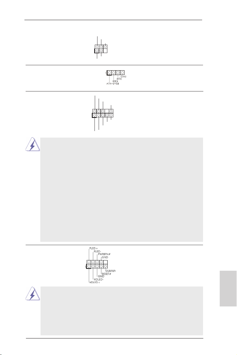
1
IRTX
+5VS B
DUMM Y
IRRX
GND
(5-pin IR1)
optional wireless transmitting
(see p.2 No. 26)
and receiving infrared module.
Consumer Infrared Module Header This header can be used to
(4-pin CIR1)
(see p.2 No. 23)
connect the remote
controller receiver.
1
GND
PRE SENC E#
MIC 2_R
MIC 2_L
MIC _RET
J_S ENSE
OUT 2_R
OUT _RET
OUT 2_L
Front Panel Audio Header This is an interface for the front
(9-pin HD_AUDIO1)
(see p.2 No. 30)
panel audio cable that allows
convenient connection and
control of audio devices.
1. High Denition Audio supports Jack Sensing, but the panel wire on
the chassis must support HDA to function correctly. Please follow the
instruction in our manual and chassis manual to install your system.
2. If you use AC’97 audio panel, please install it to the front panel audio
header as below:
A. Connect Mic_IN (MIC) to MIC2_L.
B. Connect Audio_R (RIN) to OUT2_R and Audio_L (LIN) to OUT2_L.
C. Connect Ground (GND) to Ground (GND).
D. MIC_RET and OUT_RET are for HD audio panel only. You don’t
need to connect them for AC’97 audio panel.
E. To activate the front mic.
For Windows® XP / XP 64-bit OS:
Select “Mixer”. Select “Recorder”. Then click “FrontMic”.
For Windows® 7 / 7 64-bit / VistaTM / VistaTM 64-bit OS:
Go to the "FrontMic" Tab in the Realtek Control panel. Adjust
“Recording Volume”.
System Panel Header This header accommodates
(9-pin PANEL1)
(see p.2 No. 17)
several system front panel
functions.
Connect the power switch, reset switch and system status indicator
on the chassis to this header according to the pin assignments below.
English
Note the positive and negative pins before connecting the cables.
PWRBTN (Power Switch):
Connect to the power switch on the chassis front panel. You may congure the way to turn off your system using the power switch.
29
ASRock A75 Pro4-M Motherboard
Page 30
RESET (Reset Switch):
Connect to the reset switch on the chassis front panel. Press the reset
switch to restart the computer if the computer freezes and fails to perform a normal restart.
PLED (System Power LED):
Connect to the power status indicator on the chassis front panel. The
LED is on when the system is operating. The LED keeps blinking
when the sys-tem is in S1 sleep state. The LED is off when the system
is in S3/S4 sleep state or powered off (S5).
HDLED (Hard Drive Activity LED):
Connect to the hard drive activity LED on the chassis front panel. The
LED is on when the hard drive is reading or writing data.
The front panel design may differ by chassis. A front panel module
mainly consists of power switch, reset switch, power LED, hard drive
activity LED, speaker and etc. When connecting your chassis front
panel module to this header, make sure the wire assignments and the
pin assign-ments are matched correctly.
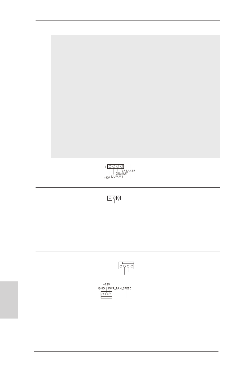
Chassis Speaker Header Please connect the chassis
(4-pin SPEAKER 1)
(see p.2 No. 18)
speaker to this header.
English
Power LED Header Please connect the chassis
(3-pin PLED1)
(see p.2 No. 20)
power LED to this header to
indicate system power status.
1
PLE D+
PLE D+
PLE D-
The LED is on when the system
is operating. The LED keeps
blinking in S1 state. The LED is
off in S3/S4 state or S5 state
(power off).
Chassis and Power Fan Connectors Please connect the fan cables
(4-pin CHA_FAN1)
(see p.2 No. 22)
ground pin.
(3-pin PWR_FAN1)
(see p.2 No. 2)
to the fan connectors and
match the black wire to the
FAN _SPE ED_C ONTR OL
CHA _FAN _SPE ED
+12 V
GND
30
ASRock A75 Pro4-M Motherboard
Page 31

CPU Fan Connectors Please connect the CPU fan
(4-pin CPU_FAN1)
(see p.2 No. 5)
cable to the connector and
match the black wire to the
ground pin.
FAN_ SPEE D_CO NTRO L
CPU _FAN_ SPEE D
+12 V
GND
1 2 3 4
Though this motherboard provides 4-Pin CPU fan (Quiet Fan) support, the 3-Pin
CPU fan still can work successfully even without the fan speed control function.
If you plan to connect the 3-Pin CPU fan to the CPU fan connector on this
motherboard, please connect it to Pin 1-3.
Pin 1-3 Connected
3-Pin Fan Installation
(3-pin CPU_FAN2)
(see p.2 No. 6)
GND
+12 V
CPU _FAN_ SPEE D
ATX Power Connector Please connect an ATX power
(24-pin ATXPWR1)
(see p.2 No. 9)
Though this motherboard provides 24-pin ATX power connector,
it can still work if you adopt a traditional 20-pin ATX power supply.
supply to this connector.
12
24
1
13
12
To use the 20-pin ATX power supply, please plug your power
supply along with Pin 1 and Pin 13.
20-Pin ATX Power Supply Installation
ATX 12V Power Connector Please connect an ATX 12V
(8-pin ATX12V1)
(see p.2 No. 1)
power supply to this connector.
8 5
4 1
1
Though this motherboard provides 8-pin ATX 12V power connector, it can still work
if you adopt a traditional 4-pin ATX 12V power supply. To use the 4-pin ATX power
supply, please plug your power supply along with Pin 1 and Pin 5.
8 5
4-Pin ATX 12V Power Supply Installation
4 1
24
13
English
ASRock A75 Pro4-M Motherboard
31
Page 32

Serial port Header This COM1 header supports a
(9-pin COM1)
(see p.2 No.28)
serial port module.
HDMI_SPDIF Header HDMI_SPDIF header, providing
(2-pin HDMI_SPDIF1)
see p.2 No. 29)
(
SPDIF audio output to HDMI
VGA card, allows the system to
connect HDMI Digital TV/
projector/LCD devices. Please
connect the HDMI_SPDIF
connector of HDMI VGA card to
this header.
English
32
ASRock A75 Pro4-M Motherboard
Page 33

2.11 Driver Installation Guide
To install the drivers to your system, please insert the support CD to your optical
drive rst. Then, the drivers compatible to your system can be auto-detected and
listed on the support CD driver page. Please follow the order from up to bottom side
to install those required drivers. Therefore, the drivers you install can work properly.
2.12 Installing Windows® 7 / 7 64-bit / VistaTM / VistaTM 64-bit / XP /
XP 64-bit With RAID Functions
If you want to install Windows® 7 / 7 64-bit / VistaTM / VistaTM 64-bit / XP / XP 64bit on your SATA3 HDDs with RAID functions, please refer to the document at the
following path in the Support CD for detailed procedures:
..\ RAID Installation Guide
2.13 Installing Windows® 7 / 7 64-bit / VistaTM / VistaTM 64-bit / XP /
XP 64-bit Without RAID Functions
If you want to install Windows® 7 / 7 64-bit / VistaTM / VistaTM 64-bit / XP / XP 64-bit
OS on your SATA3 HDDs without RAID functions, please follow below procedures
according to the OS you install.
2.13.1 Installing Windows® XP / XP 64-bit Without RAID Functions
If you want to install Windows® XP / XP 64-bit on your SATA3 HDDs without RAID
functions, please follow below steps.
Using SATA3 HDDs without NCQ and Hot Plug functions (IDE mode)
STEP 1: Set up UEFI.
A. Enter UEFI SETUP UTILITY Advanced screen Storage
Conguration.
B. Set the “SATA Mode” option to [IDE].
STEP 2: Install Windows® XP / XP 64-bit OS on your system.
ASRock A75 Pro4-M Motherboard
English
33
Page 34

2.13.2 Installing Windows® 7 / 7 64-bit / VistaTM / VistaTM 64-bit
Without RAID Functions
If you want to install Windows® 7 / 7 64-bit / VistaTM / VistaTM 64-bit on your SATA3
HDDs without RAID functions, please follow below steps.
Using SATA3 HDDs without NCQ and Hot Plug functions (IDE mode)
STEP 1: Set up UEFI.
A. Enter UEFI SETUP UTILITY Advanced screen Storage
Conguration.
B. Set the “SATA Mode” option to [IDE].
STEP 2: Install Windows® 7 / 7 64-bit / VistaTM / VistaTM 64-bit OS on your
system.
Using SATA3 HDDs with NCQ and Hot Plug functions (AHCI mode)
STEP 1: Set up UEFI.
A. Enter UEFI SETUP UTILITY Advanced screen Storage
Conguration.
B. Set the “SATA Mode” option to [AHCI].
STEP 2: Install Windows® 7 / 7 64-bit / VistaTM / VistaTM 64-bit OS on your
system.
English
34
ASRock A75 Pro4-M Motherboard
Page 35

3. BIOS Information
The Flash Memory on the motherboard stores BIOS Setup Utility. When you start up
the computer, please press <F2> or <Del> during the Power-On-Self-Test (POST)
to enter BIOS Setup utility; otherwise, POST continues with its test routines. If you
wish to enter BIOS Setup after POST, please restart the system by pressing <Ctl>
+ <Alt> + <Delete>, or pressing the reset button on the system chassis. The BIOS
Setup program is designed to be user-friendly. It is a menu-driven program, which
allows you to scroll through its various sub-menus and to select among the predetermined choices. For the detailed information about BIOS Setup, please refer to the
User Manual (PDF le) contained in the Support CD.
4. Software Support CD information
®
This motherboard supports various Microsoft
64-bit / VistaTM / Vista
the motherboard contains necessary drivers and useful utilities that will enhance
motherboard features. To begin using the Support CD, insert the CD into your CDROM drive. It will display the Main Menu automatically if “AUTORUN” is enabled in
your computer. If the Main Menu does not appear automatically, locate and doubleclick on the le “ASSETUP.EXE” from the BIN folder in the Support CD to display
the menus.
TM
64-bit / XP SP3 / XP 64-bit. The Support CD that came with
Windows® operating systems: 7 / 7
ASRock A75 Pro4-M Motherboard
English
35
Page 36

1. Einführung
Wir danken Ihnen für den Kauf des ASRock A75 Pro4-M Motherboard, ein zuverlässiges Produkt, welches unter den ständigen, strengen Qualitätskontrollen von
ASRock gefertigt wurde. Es bietet Ihnen exzellente Leistung und robustes Design,
gemäß der Verpflichtung von ASRock zu Qualität und Halbarkeit. Diese Schnellinstallationsanleitung führt in das Motherboard und die schrittweise Installation
ein. Details über das Motherboard nden Sie in der Bedienungsanleitung auf der
Support-CD.
Da sich Motherboard-Spezikationen und BIOS-Software verändern
können, kann der Inhalt dieses Handbuches ebenfalls jederzeit geändert
werden. Für den Fall, dass sich Änderungen an diesem Handbuch
ergeben, wird eine neue Version auf der ASRock-Website, ohne weitere
Ankündigung, verfügbar sein. Die neuesten Grakkarten und unterstützten
CPUs sind auch auf der ASRock-Website aufgelistet.
ASRock-Website: http://www.asrock.com
Wenn Sie technische Unterstützung zu Ihrem Motherboard oder spezische
Informationen zu Ihrem Modell benötigen, besuchen Sie bitte unsere
Webseite:
www.asrock.com/support/index.asp
1.1 Kartoninhalt
ASRock A75 Pro4-M Motherboard
(Micro ATX-Formfaktor: 24.4 cm x 24.4 cm; 9.6 Zoll x 9.6 Zoll)
ASRock A75 Pro4-M Schnellinstallationsanleitung
ASRock A75 Pro4-M Support-CD
Zwei Serial ATA (SATA) -Datenkabel (optional)
Ein I/O Shield
Deutsch
36
ASRock erinnert...
Zur besseren Leistung unter Windows® 7 / 7, 64 Bit / Vista
64 Bit empfehlen wir, die Speicherkonguration im BIOS auf den AHCIModus einzustellen. Hinweise zu den BIOS-Einstellungen nden Sie in
der Bedienungsanleitung auf der mitgelieferten CD.
TM
/ VistaTM
ASRock A75 Pro4-M Motherboard
Page 37

1.2 Spezifikationen
Plattform - Micro ATX-Formfaktor: 24.4 cm x 24.4 cm; 9.6 Zoll x 9.6 Zoll
- Alle Feste Kondensatordesign
CPU - Unterstützt Sockel-FM1-100-W-Prozessoren
- V4 + 1-Stromphasendesign
- Unterstützt Cool ‘n’ QuietTM-Technologie von AMD
- UMI-Link-GEN2
Chipsatz - AMD A75 FCH (Hudson-D3)
Speicher - Unterstützung von Dual-Kanal-Speichertechnologie
(siehe VORSICHT 1)
- 4 x Steckplätze für DDR3
- Unterstützt DDR3 2400+(OC)/1866/1600/1333/
1066/800 non-ECC, ungepufferter Speicher
(siehe VORSICHT 2)
- Max. Kapazität des Systemspeichers: 32GB
(siehe VORSICHT 3)
Erweiterungs- - 2 x PCI-Express-2.0-x16-Steckplätze
steckplätze (PCIE1: x16-Modus; PCIE2: x4-Modus)
- 2 x PCI -Steckplätze
- Unterstützt AMD Quad CrossFireXTM, CrossFireXTM und
duale Grakkarten
Onboard-VGA - AMD Radeon HD 65XX/64XX-Grak
- DirectX 11, Pixel Shader 5.0
- Maximal gemeinsam genutzter Speicher 512MB
(siehe VORSICHT 4)
- Drei VGA-Ausgangsoptionen: D-Sub, DVI-D sowie HDMI
(siehe VORSICHT 5)
- Unterstützt HDMI 1.4a mit einer maximalen Auösung von
1920 x 1200 bei 60 Hz
- Unterstützt Dual-link DVI mit einer maximalen Auösung von
2560 x 1600 bei 75 Hz
- Unterstützt D-Sub mit einer maximalen Auösung von
1920 x 1600 bei 60 Hz
- Unterstützt Auto Lip Sync, Deep Color (12bpc), xvYCC und
HBR (High Bit Rate-Audio) mit HDMI (kompatibler HDMI-
Bildschirm erforderlich) (siehe VORSICHT 6)
- Unterstützt stereoskopisches 3D per Blu-ray mit HDMI 1.4a
- Unterstützt AMD Steady VideoTM: Neuartige Funktion der
Videonachbearbeitung für automatische Reduzierung von
Bildschwankungen bei Heim-/Online-Videos
- Unterstützt HDCP-Funktion mit DVI- und HDMI-Ports
ASRock A75 Pro4-M Motherboard
Deutsch
37
Page 38

Deutsch
38
- Unterstutzt 1080p Blu-ray (BD) / HD-DVD-Wiedergabe mit
DVI- und HDMI-Ports
Audio - 7.1 CH HD Audio mit dem Inhalt Schutz
(Realtek ALC892 Audio Codec)
- Premium Blu-ray-Audio-Unterstützung
- Unterstützt THX TruStudio
TM
LAN - PCIE x1 Gigabit LAN 10/100/1000 Mb/s
- Realtek RTL8111E
- Unterstützt Wake-On-LAN
- Unterstützt LAN-Kabelerkennung
- Unterstützt energieefzientes Ethernet 802.3az
- Unterstützt PXE
E/A-Anschlüsse I/O Panel
an der - 1 x PS/2-Maus/Tastaturanschluss
Rückseite - 1 x D-Sub port
- 1 x DVI-D port
- 1 x HDMI port
- 1 x optischer SPDIF-Ausgang
- 2 x Standard-USB 2.0-Anschlüsse
- 1 x eSATA3-Anschluss
- 4 x Standard-USB 3.0-Anschlüsse
- 1 x RJ-45 LAN Port mit LED (ACT/LINK LED und SPEED
LED)
- HD Audiobuchse: Lautsprecher hinten / Mitte/Bass /
Audioeingang / Lautsprecher vorne / Mikrofon
(siehe VORSICHT 7)
SATA3 - 5 x SATA 3-Anschluss mit 6,0 Gb/s, unterstützt RAID (RAID 0, RAID 1 und RAID 10), NCQ-, AHCI- und „Hot
Plugging“-Funktionen
USB3.0 - 4 x USB 3.0-Ports, unterstützt USB 1.0/2.0/3.0 mit bis zu
5 Gb/s
Anschlüsse - 5 x SATA3 6,0 GB/s-Anschlüsse
- 1 x Infrarot-Modul-Header
- 1 x Consumer Infrarot-Modul-Header
- 1 x Druckerport-Anschlussleiste
- 1 x COM-Anschluss-Header
- 1 x HDMI_SPDIF-Anschluss
- 1 x Betriebs-LED-Header
- CPU/Gehäuse/Stromlüfter-Anschluss
- 24-pin ATX-Netz-Header
- 8-pin anschluss für 12V-ATX-Netzteil
- Anschluss für Audio auf der Gehäusevorderseite
ASRock A75 Pro4-M Motherboard
Page 39

- 3 x USB 2.0-Anschlüsse (Unterstützung 6 zusätzlicher
USB 2.0-Anschlüsse)
BIOS - 32Mb AMIs Legal BIOS UEFI mit GUI-Unterstützung
- Unterstützung für “Plug and Play”
- ACPI 1.1-Weckfunktionen
- JumperFree-Modus
- SMBIOS 2.3.1
- DRAM, VDDP, VDDR, SB Stromspannung Multianpassung
Support-CD - Treiber, Dienstprogramme, Antivirussoftware
(Probeversion), CyberLink MediaEspresso 6.5-Testversion
Einzigartige - ASRock Extreme Tuning Utility (AXTU)
Eigenschaft (siehe VORSICHT 8)
- ASRock Sofortstart
- ASRock Instant Flash (siehe VORSICHT 9)
- ASRock APP Charger (siehe VORSICHT 10)
- ASRock XFast USB (siehe VORSICHT 11)
- ASRock ein/aus-Wiedergabetechnologie
(siehe VORSICHT 12)
- Hybrid Booster:
- ASRock U-COP (siehe VORSICHT 13)
Hardware Monitor - CPU-Temperatursensor
- Motherboardtemperaturerkennung
- Drehzahlmessung für CPU/Gehäuse/Stromlüfter
- Geräuscharmer CPU-/Gehäuselüfter
- Mehrstuge Geschwindigkeitsteuerung für CPU-/
Gehäuselüfter
- Spannungsüberwachung: +12V, +5V, +3.3V, Vcore
®
Betriebssysteme - Unterstützt Microsoft
Vista
TM
64-Bit / XP SP3 / XP 64-Bit
Windows® 7 / 7 64-Bit / VistaTM /
Zertizierungen - FCC, CE, WHQL
- Gemäß Ökodesign-Richtlinie (ErP/EuP) (Stromversorgung
gemäß Ökodesign-Richtlinie (ErP/EuP) erforderlich)
(siehe VORSICHT 14)
* Für die ausführliche Produktinformation, besuchen Sie bitte unsere Website:
http://www.asrock.com
ASRock A75 Pro4-M Motherboard
Deutsch
39
Page 40

Deutsch
WARNUNG
Beachten Sie bitte, dass Overclocking, einschließlich der Einstellung im BIOS, Anwenden
der Untied Overclocking-Technologie oder Verwenden von Overclocking-Werkzeugen von
Dritten, mit einem gewissen Risiko behaftet ist. Overclocking kann sich nachteilig auf die
Stabilität Ihres Systems auswirken oder sogar Komponenten und Geräte Ihres Systems
beschädigen. Es geschieht dann auf eigene Gefahr und auf Ihre Kosten. Wir übernehmen
keine Verantwortung für mögliche Schäden, die aufgrund von Overclocking verursacht wurden.
VORSICHT!
Dieses Motherboard unterstützt Dual-Kanal-Speichertechnologie. Vor
1.
Implementierung der Dual-Kanal-Speichertechnologie müssen Sie die
Installationsanleitung für die Speichermodule auf Seite 45 zwecks richtiger
Installation gelesen haben.
2. Ob die Speichergeschwindigkeit 2400/1866/1600 MHz unterstützt wird,
hängt von der von Ihnen eingesetzten CPU ab. Schauen Sie bitte auf unseren Internetseiten in der Liste mit unterstützten Speichermodulen nach,
wenn Sie DDR3 2400/1866/1600-Speichermodule einsetzen möchten.
ASRock-Internetseite: http://www.asrock.com
3. Durch Betriebssystem-Einschränkungen kann die tatsächliche Speichergröße weniger als 4 GB betragen, da unter Windows® 7 / VistaTM / XP
etwas Speicher zur Nutzung durch das System reserviert wird. Unter
Windows® OS mit 64-Bit-CPU besteht diese Einschränkung nicht.
4. Die Maximalspeichergröße ist von den Chipshändler deniert und umgetauscht. Bitte überprüfen Sie AMD website für die neuliche Information.
5. Sie können nur die Nutzung von zwei von drei Bildschirmen auswählen.
Die D-Sub-, DVI-D- und HDMI-Bildschirme können nicht gleichzeitig
aktiviert werden. Zudem kann der DVI-D-Port mit DVI-zu-HDMI-Adapter
dieselben Funktionen wie der HDMI-Port unterstützen.
6. xvYCC und Deep Color werden nur unter Windows® 7 64-Bit / 7 unterstützt. Der Deep Color-Modus wird nur aktiviert, wenn der Bildschirm
12bpc in EDID unterstützt. HBR wird unter Windows® 7 64 Bit / 7 / VistaTM
64 Bit / VistaTM unterstützt.
7. Der Mikrofoneingang dieses Motherboards unterstützt Stereo- und MonoModi. Der Audioausgang dieses Motherboards unterstützt 2-Kanal-,
4-Kanal-, 6-Kanal- und 8-Kanal-Modi. Stellen Sie die richtige Verbindung
anhand der Tabelle auf Seite 3 her.
8. ASRock Extreme Tuning Utility (AXTU) ist ein Alles-in-einem-
Werkzeug zur Feineinstellung verschiedener Systemfunktionen an
einer benutzerfreundlichen Schnittstelle; diese beinhaltet
HardwareÜberwachung, Lüftersteuerung und IES. Über die Hardware-
Überwachung können Sie die Hauptsystemdaten einsehen. Die
Lüftersteuerung zeigt Ihnen zur Anpassung Lüftergeschwindigkeit und
Temperatur an. Per IES (Intelligent Energy Saver) kann der Spannungsregulator bei Inaktivität der CPU-Kerne die Anzahl an Ausgangsphasen
40
ASRock A75 Pro4-M Motherboard
Page 41

zur Steigerung der Ef zienz reduzieren – ohne die Rechenleistung zu
beeinträchtigen. Hinweise zur Bedienung der ASRock Extreme Tuning
Utility (AXTU) nden Sie auf unserer Webseite. ASRock-Webseite: http://
www.asrock.com
9. ASRock Instant Flash ist ein im Flash-ROM eingebettetes BIOS-FlashProgramm. Mithilfe dieses praktischen BIOS-Aktualisierungswerkzeugs
können Sie das System-BIOS aktualisieren, ohne dafür zuerst Betriebssysteme wie MS-DOS oder Windows® aufrufen zu müssen. Mit diesem
Programm bekommen Sie durch Drücken der <F6>-Taste während des
POST-Vorgangs oder durch Drücken der <F2>-Taste im BIOS-SetupMenü Zugang zu ASRock Instant Flash. Sie brauchen dieses Werkzeug
einfach nur zu starten und die neue BIOS-Datei auf Ihrem USB-FlashLaufwerk, Diskettenlaufwerk oder der Festplatte zu
speichern, und schon können Sie Ihr BIOS mit nur wenigen Klickvorgän-
gen ohne Bereitstellung einer zusätzlichen Diskette oder eines anderen komplizierten Flash-Programms aktualisieren. Achten Sie darauf,
dass das USB-Flash-Laufwerk oder die Festplatte das Dateisystem
FAT32/16/12 benutzen muss.
10. Wenn Sie nach einer schnelleren, weniger eingeschränkten Möglichkeit zur Auadung Ihrer Apple-Geräte (z. B. iPhone/iPad/iPod touch)
suchen, bietet ASRock Ihnen eine wunderbare Lösung – den ASRock
APP Charger. Installieren Sie einfach den ASRock APP Charger-Treiber;
dadurch lädt sich Ihr iPhone wesentlich schneller über einen Computer
auf – genaugenommen bis zu 40 % schneller als zuvor. Der ASRock APP
Charger ermöglicht Ihnen die schnelle Auadung mehrerer Apple-Geräte
gleichzeitig; der Ladevorgang wird sogar dann fortgesetzt, wenn der PC
den Ruhezustand (S1), Suspend to RAM-Modus (S3) oder Tiefschlafmodus (S4) aufruft oder ausgeschaltet wird (S5). Nach der
Installation des APP Charger-Treibers können Sie im Handumdrehen das
großartigste Ladeerlebnis überhaupt genießen.
ASRock-Webseite: http://www.asrock.com/Feature/AppCharger/index.
asp
11. ASRocks XFast USB dient der Steigerung der Leistungsfähigkeit Ihrer
USB-Speichergeräte. Die Leistung kann je nach Eigenschaften des Gerätes variieren.
12. Durch die ASRock ein/aus-Wiedergabetechnologie können Sie großartige
Klangerlebnisse von portablen Audiogeräten, wie z. B. MP3-Playern oder
Mobiltelefonen, an Ihrem PC genießen – selbst wenn der PC ausgeschaltet ist (oder sich im ACPI S5-Modus bendet)! Dieses Motherboard
wird zudem mit einem kostenlosen Audiokabel (3,5 mm, Klinke) (optional)
geliefert, was eine IT-Umgebung von höchster Benutzerfreundlichkeit
gewährleistet.
Deutsch
ASRock A75 Pro4-M Motherboard
41
Page 42

13. Wird eine Überhitzung der CPU registriert, führt das System einen automati-
schen Shutdown durch. Bevor Sie das System neu starten, prüfen Sie bitte,
ob der CPU-Lüfter am Motherboard richtig funktioniert, und stecken Sie bitte
den Stromkabelstecker aus und dann wieder ein. Um die Wärmeableitung
zu verbessern, bitte nicht vergessen, etwas Wärmeleitpaste zwischen CPU
und Kühlkörper zu sprühen.
14. EuP steht für Energy Using Product und kennzeichnet die Ökodesign-
Richtlinie, die von der Europäischen Gemeinschaft zur Festlegung des
Energieverbrauchs von vollständigen Systemen in Kraft gesetzt wurde.
Gemäß dieser Ökodesign-Richtlinie (EuP) muss der gesamte Netzstromverbrauch von vollständigen Systemen unter 1,00 Watt liegen, wenn sie
ausgeschaltet sind. Um dem EuP-Standard zu entsprechen, sind ein EuPfähiges Motherboard und eine EuP-fähige Stromversorgung erforderlich.
Gemäß einer Empfehlung von Intel muss eine EuP-fähige Stromversorgung
dem Standard entsprechen, was bedeutet, dass bei einem Stromverbrauch
von 100 mA die 5-Volt-Standby-Energieefzienz höher als 50% sein sollte.
Für die Wahl einer EuP-fähigen Stromversorgung empfehlen wir Ihnen,
weitere Details beim Hersteller der Stromversorgung abzufragen. Beachten
Sie bitte überdies, dass bei Aktivierung der ASRock On/Off Play-Technologie
Ihrerseits, Ihr System den EuP-Standard nicht erfüllt. Zur Übereinstimmung
mit dem EuP-Standard deaktivieren Sie bitte zuerst die ASRock On/Off PlayTechnologie.
Deutsch
42
ASRock A75 Pro4-M Motherboard
Page 43

2. Installation
Dies ist ein Motherboard mit einem Micro ATX-Formfaktor (9,6 Zoll x 9,6 Zoll, 24,4
cm x 24,4 cm). Vor Installation des Motherboards müssen Sie die Konguration
Ihres Gehäuses dahingehend überprüfen, ob das Motherboard dort hineinpasst.
Sicherheitshinweise vor der Montage
Bitte nehmen Sie die folgende Sicherheitshinweise zur Kenntnis, bevor
Sie das Motherboard einbauen oder Veränderungen an den Einstellungen
vornehmen.
Vor dem Ein- oder Ausbauen einer Komponent müssen Sie sicherstellen,
dass der Netzschalter ausgeschaltet oder die Netzleitung von der Steckdose
abgezogen ist. Andernfalls könnten das Motherboard, Peripheriegeräte und/
oder Komponenten schwer beschädigt werden.
1. Trennen Sie das System vom Stromnetz, bevor Sie eine
Systemkomponente berühren, da es sonst zu schweren Schäden am
Motherboard oder den sonstigen internen, bzw. externen Komponenten
kommen kann.
2. Um Schäden aufgrund von statischer Elektrizität zu vermeiden, das
Motherboard NIEMALS auf einen Teppich o.ä.legen. Denken
Sie außerem daran, immer ein geerdetes Armband zu tragen
oder ein geerdetes Objekt aus Metall zu berühren, bevor Sie mit
Systemkomponenten hantieren.
3. Halten Sie Komponenten immer an den Rändern und vermeiden Sie
Berührungen mit den ICs.
4. Wenn Sie Komponenten ausbauen, legen Sie sie immer auf eine
antistatische Unterlage, oder zurück in die Tüte, mit der die Komponente
geliefert wurde.
5. Wenn Sie das Motherboard mit den Schrauben an dem
Computergehäuse befestigen, überziehen Sie bitte die Schrauben nicht!
Das Motherboard kann sonst beschädigt werden.
ASRock A75 Pro4-M Motherboard
Deutsch
43
Page 44

2.1 CPU Installation
Schritt 1: Öffnen Sie den CPU-Sockel, indem sie den Hebel leicht zur Seite und
dann nach oben ziehen, auf einen Winkel von 90°.
Schritt 2: Positionieren Sie die CPU genau so über dem Sockel, dass sich die
Ecke der CPU mit dem goldenen Dreieck exakt über der Ecke des
Sockels bendet, die mit einem kleinen Dreieck gekennzeichnet ist.
Schritt 3: Drücken Sie die CPU vorsichtig in den Sockel.
nicht mit Gewalt in den Sockel, damit sich die Pins nicht verbiegen.
Überprüfen Sie die Ausrichtung und suchen nach verbogenen Pins,
sollte die CPU nicht in den Sockel passen.
Schritt 4: Wenn die CPU korrekt im Sockel sitzt, leicht mit dem Finger
draufdrücken und gleichzeitig den Hebel nach unten drücken, bis er
hörbar einrastet.
Die CPU sollte problemlos in den Sockel passen. Drücken Sie die CPU
Hebel 90°
nach oben
Goldenes Dreieck der CPU
Kleines Dreieck der
Sockelecke
SCHRITT 1:
Ziehen Sie den Sockelhebel hoch
SCHRITT 2 / SCHRITT 3:
Richten Sie das goldene
Dreieck der CPU mit dem
kleinen Dreieck der
Sockelecke aus
SCHRITT 4:
Drücken Sie den Sockelhebel nach unten und rasten
Sie ihn ein
Deutsch
2.2 Installation des CPU-Lüfters und des Kühlkörpers
Nachdem Sie die CPU auf diesem Motherboard installiert haben, müssen
Sie einen größeren Kühlkörper und Lüfter installieren, um Wärme
abzuleiten. Zwischen CPU und Kühlkörper müssen Sie auch
Wärmeleitpaste auftragen, um die Wärmeableitung zu verbessern.
Vergewissern Sie sich, dass die CPU und der Kühlkörper gut befestigt
sind und einen guten Kontakt zueinander haben. Verbinden Sie dann den
CPU-Lüfter mit dem CPU-LÜFTER-Anschluss (CPU_FAN1, siehe Seite 2,
Nr. 5 oder CPU_FAN2, siehe Seite 2, Nr. 6). Beziehen Sie sich für eine
richtige Installation auf die Handbücher des CPU-Lüfters und des
Kühlkörpers.
44
ASRock A75 Pro4-M Motherboard
Page 45
2.3 Installation der Speichermodule (DIMM)
Die Motherboards A75 Pro4-M bieten vier 240-pol. DDR3 (Double Data Rate 3)
DIMM-Steckplätze und unterstützen die Dual-Kanal-Speichertechnologie. Für die
Dual-Kanalkonguration dürfen Sie nur identische (gleiche Marke, Geschwindigkeit,
Größe und gleicher Chiptyp) DDR3 DIMM-Paare in den Steckplätzen gleicher Farbe
installieren. Mit anderen Worten, sie müssen ein identisches DDR3 DIMM-Paar im
Dual-Kanal A (DDR3_A1 und DDR3_B1; Blau Steckplätze, siehe Seite 2 Nr. 7) oder
ein identisches DDR3 DIMM-Paar im Dual-Kanal B (DDR3_A2 und DDR3_B2; Weiß
Steckplätze, siehe Seite 2 Nr. 8) installieren, damit die Dual-Kanal-Speichertechnologie aktiviert werden kann. Auf diesem Motherboard können Sie auch vier DDR3
DIMMs für eine Dual-Kanalkonguration installieren. Auf diesem Motherboard können Sie auch vier DDR3 DIMM-Module für eine Dual-Kanalkonguration installieren,
wobei Sie bitte in allen vier Steckplätzen identische DDR3 DIMM-Module installieren. Beziehen Sie sich dabei auf die nachstehende Kongurationstabelle für DualKanalspeicher.
Dual-Kanal-Speicherkongurationen
DDR3_A1 DDR3_A2 DDR3_B1 DDR3_B2
(Blau) (Weiß) (Blau) (Weiß)
(1) Bestückt - Bestückt (2) - Bestückt - Bestückt
(3)* Bestückt Bestückt Bestückt Bestückt
* Für Konguration (3) installieren Sie bitte identische DDR3 DIMMs in allen vier
Steckplätzen.
1. Wenn Sie zwei Speichermodule installieren möchten, verwenden Sie
dazu für optimale Kompatibilität und Stabilität Steckplätze gleicher
Farbe. Installieren Sie die beiden Speichermodule also entweder in
den blau Steckplätzen (DDR3_A1 und DDR3_B1) oder den Weiß
Steckplätzen (DDR3_A2 und DDR3_B2).
2. Wenn nur ein Speichermodul oder drei Speichermodule in den DDR3
DIMM-Steckplätzen auf diesem Motherboard installiert sind, kann es
die Dual-Kanal-Speichertechnologie nicht aktivieren.
3. Ist ein Speichermodulpaar NICHT im gleichen “Dual-Kanal” installiert,
z.B. ein Speichermodulpaar wird in DDR3_A1 und DDR3_A2 installiert, kann es die Dual-Kanal-Speichertechnologie nicht aktivieren.
4. Es ist nicht zulässig, DDR oder DDR2 in einen DDR3 Steckplatz zu
installieren; andernfalls könnten Motherboard und DIMMs beschädigt
werden.
5. Wenn Sie DDR3 2400/1866/1600-Speichermodule für dieses Motherboard übernehmen, wird empfohlen, sie in den DDR3_A2- und
DDR3_B2-Steckplätzen zu installieren.
ASRock A75 Pro4-M Motherboard
Deutsch
45
Page 46

Einsetzen eines DIMM-Moduls
Achten Sie darauf, das Netzteil abzustecken, bevor Sie DIMMs oder
Systemkomponenten hinzufügen oder entfernen.
Schritt 1: Öffnen Sie einen DIMM-Slot, indem Sie die seitlichen Clips nach außen
drücken.
Schritt 2: Richten Sie das DIMM-Modul so über dem Slot aus, dass das Modul mit
der Kerbe in den Slot passt.
Deutsch
Die DIMM-Module passen nur richtig herum eingelegt in die Steckplätze. Falls Sie versuchen, die DIMM-Module mit Gewalt falsch herum
in die Steckplätze zu zwingen, führt dies zu dauerhaften Schäden am
Mainboard und am DIMM-Modul.
Schritt 3: Drücken Sie die DIMM-Module fest in die Steckplätze, so dass die
Halteklammern an beiden Enden des Moduls einschnappen und das
DIMM-Modul fest an Ort und Stelle sitzt.
46
ASRock A75 Pro4-M Motherboard
Page 47

2.4 Erweiterungssteckplätze: (PCI- und PCI Express-Slots):
Es stehen 2 PCI- und 2 PCI Express-Slot auf dem A75 Pro4-M Motherboard zur
Verfügung.
PCI-Slots: PCI-Slots werden zur Installation von Erweiterungskarten mit dem
32bit PCI-Interface genutzt.
PCI Express-Slots:
PCIE1 (PCIE x16-Steckplatz; blau) wird für PCI Express x16
Lane-Breite-Grakkarten oder für die Installation von PCI
Express-Grakkarten verwendet, um die CrossFireXTM-Funktion
zu unterstützen.
PCIE2 (PCIE x16-Steckplatz; blau) wird für PCI Express x4
Lane-Breite-Karten verwendet, oder für die Installation von PCI
Express-Grakkarten, um die CrossFireXTM-Funktion zu
unterstützen.
1. Im Einzel-VGA-Kartenmodus wird empfohlen, eine PCI Express
x16-Grakkarte im PCIE1-Steckplatz zu installieren.
2. Im CrossFireXTM-Modus installieren Sie PCI Express x16- Grakkarten
in den PCIE1- und PCIE2-Steckplätzen.
Einbau einer Erweiterungskarte
Schritt 1: Bevor Sie die Erweiterungskarte installieren, vergewissern Sie sich,
dass das Netzteil ausgeschaltet und das Netzkabel abgezogen ist.
Bitte lesen Sie die Dokumentation zur Erweiterungskarte und nehmen
Sie nötige Hardware-Einstellungen für die Karte vor, ehe Sie mit der
Installation beginnen.
Schritt 2: Entfernen Sie das Abdeckungsblech (Slotblende) von dem
Gehäuseschacht (Slot) , den Sie nutzen möchten und behalten die
Schraube für den Einbau der Karte.
Schritt 3: Richten Sie die Karte über dem Slot aus und drücken Sie sie ohne
Gewalt hinein, bis sie den Steckplatz korrekt ausfüllt.
Schritt 4: Befestigen Sie die Karte mit der Schraube aus Schritt 2.
ASRock A75 Pro4-M Motherboard
Deutsch
47
Page 48

2.5 CrossFireXTM- und Quad CrossFireXTM Bedienungsanleitung
Dieses Motherboard unterstützt die CrossFireXTM- und Quad CrossFireXTM-Funktion.
CrossFireXTM-Technologie bietet die am vorteilhaftesten zur Verfügung stehende
Methode zur Kombination mehrerer leistungsstarker Grakprozessoren (GPU) in einem einzelnen PC. Die Kombination einer Reihe unterschiedlicher Betriebsmodi mit
intelligentem Softwaredesign und einem innovativen Schaltmechanismus ermöglicht CrossFireXTM die optimalste Leistung und Bildqualität in einer 3D-Anwendung.
Derzeit wird die CrossFireXTM-Funktion von den Betriebssystemen Windows® XP mit
Service Pack 2 / VistaTM / 7 unterstützt. Die Quad CrossFireXTM-Funktion wird nur
vom Betriebssystem Windows® VistaTM / 7 unterstützt. Schauen Sie auf der AMDWebsite nach, ob es AMD CrossFireXTM-Treiber-Updates gibt. Beachten Sie den
detailliert erklärten Installationsablauf auf Seite 17.
2.6 Bedienungsanleitung für AMD duale Grafikkarten
Dieses Motherboard unterstützt die Funktion AMD duale Grakkarten. AMD duale
Grakkarten bietet durch Aktivierung eines im AMD A75 FCH (Hudson-D3) integrierten Grakprozessors und eines eigenständigen Grakprozessors einen MultiGPU-Leistungsumfang, um gleichzeitig mit kombinierter Ausgabe auf einem einzigen Anzeigegerät für superschnelle Bildwiederholraten zu sorgen. Derzeit wird AMD
duale Grakkarten-Technologie nur vom Betriebssystem Windows® 7 unterstützt
und ist für das Betriebssystem Windows® VistaTM / XP nicht verfügbar. Detaillierte
Bedienschritte und kompatible PCI Express-Grakkarten sind auf Seite 21.
Deutsch
48
ASRock A75 Pro4-M Motherboard
Page 49

2.7 ASRock Smart Remote Schnellinstallationsanleitung
Die ASRock Smart Remote ist nur mit ASRock-Motherboards kompatibel, die über einen CIRHeader verfügen. Bitte beachten Sie zur schnellen Installation und Nutzung der ASRock Smart
Remote das nachstehende Verfahren.
Schritt 1. Machen Sie den CIR-Header neben
dem USB 2.0-Header auf dem
ASRock-Motherboard ausndig.
Schritt 2. Verbinden Sie das vordere USB-
Kabel mit dem USB 2.0-Header
(wie nachstehenden: Pin 1 – 5)
und CIR-Header. Stellen Sie sicher,
dass die Kabel- und Pinbelegungen
korrekt übereinstimmen.
Schritt 3. Installieren Sie den Mehrwinkel-CIR-
Empfänger am vorderen USB-Port.
Falls der Mehrwinkel-CIR-Empfänger
die Infrarotsignale der MCEFernbedienung nicht empfangen
kann, versuchen Sie bitte, ihn an
dem anderen USB-Port auf der
Vorderseite zu installieren.
USB_PWR
ATX+5VSB
P-
IRRX
P+
IRTX
GND
GND
USB 2.0-Header
(9-polig, blau)
CIR-Header
(4-polig, weiß)
DUMMY
3 CIR-Sensoren in verschiedenen Winkeln
1. Nur einer der vorderen USB-Ports kann die CIR-Funktion unterstützen.
Wenn die CIR-Funktion aktiviert ist, behält der andere Port seine USBFunktion bei.
2. Der Mehrwinkel-CIR-Empfänger dient ausschließlich der Installation an
einem der vorderen USB-Ports. Bitte versuchen Sie nicht, ihn über die
hintere USB-Halterung an der Rückblende zu installieren. Der MehrwinkelCIR-Empfänger kann Infrarotsignale aus mehreren Richtungen (oben,
unten und vorne) empfangen; dadurch ist er mit den meisten Gehäusen auf
dem Markt kompatibel.
3. Der Fernbedienungsempfänger unterstützt kein Hot-Plugging. Bitte
installieren Sie ihn, bevor Sie Ihr System hochfahren.
* Die ASRock Smart Remote wird nur von einigen ASRock-Motherboards unterstützt. Eine Liste dieser
Motherboards nden Sie auf der ASRock-Webseite: http://www.asrock.com
49
ASRock A75 Pro4-M Motherboard
Deutsch
Page 50

2.8 Einstellung der Jumper
Die Abbildung verdeutlicht, wie Jumper
gesetzt werden. Werden Pins durch
Jumperkappen verdeckt, ist der Jumper
“Gebrückt”. Werden keine Pins durch
Jumperkappen verdeckt, ist der Jumper
“Offen”. Die Abbildung zeigt einen 3-Pin
Jumper dessen Pin1 und Pin2 “Gebrückt” sind, bzw. es bendet sich eine
Jumper-Kappe auf diesen beiden Pins.
Jumper Einstellun Beschreibung
CMOS löschen
(CLRCMOS1, 3-Pin jumper)
(siehe S.2, No. 11)
Hinweis:
CLRCMOS1 ermöglicht Ihnen die Löschung der Daten im CMOS. Zum
Löschen und Zurücksetzen der Systemparameter auf die Standardeinrichtung
schalten Sie den Computer bitte aus und trennen das Netzkabel von der
Stromversorgung. Warten Sie 15 Sekunden, schließen Sie dann Pin2 und
Pin3 am CLRCMOS1 über einen Jumper fünf Sekunden lang kurz. Sie
sollten das CMOS allerdings nicht direkt nach der BIOS-Aktualisierung
löschen. Wenn Sie das CMOS nach Abschluss der BIOS-Aktualisierung
löschen müssen, fahren Sie zuerst das System hoch. Fahren Sie es dann
vor der CMOS-Löschung herunter. Bitte beachten Sie, dass Kennwort,
Datum, Uhrzeit, benutzerdeniertes Prol, 1394 GUID und MAC-Adresse
nur gelöscht werden, wenn die CMOS-Batterie entfernt wird.
DefaultEinstellung
CMOS
löschen
Deutsch
50
ASRock A75 Pro4-M Motherboard
Page 51

2.9 Anschlüsse
Anschlussleisten sind KEINE Jumper. Setzen Sie KEINE Jumperkappen
auf die Pins der Anschlussleisten. Wenn Sie die Jumperkappen auf die
Anschlüsse setzen, wird das Motherboard permanent beschädigt!
Anschluss Beschreibung
Seriell-ATA3-Anschlüsse Diese fünf Serial ATA3-
(SATA3_1: siehe S.2 - No. 15)
(SATA3_2: siehe S.2 - No. 16)
(SATA3_3: siehe S.2 - No. 14)
(SATA3_4: siehe S.2 - No. 13)
(SATA3_5: siehe S.2 - No. 12)
ermöglicht eine
(SATA3-)Verbínder
unterstützten SATA-Datenkabel
SATA3_2 SATA3_4
für interne
Massenspeichergeräte. Die
aktuelle SATA3- Schnittstelle
SATA3_1 SATA3_3
Datenübertragungsrate bis
6,0 Gb/s.
Serial ATA- (SATA-) SJedes Ende des SATA
Datenkabel Datenkabels kann an die
(Option)
SATA3 Festplatte oder das
SATA3 Verbindungsstück auf
dieser Hauptplatine
angeschlossen werden.
SATA3_5
Druckerport-Anschlussleiste Dies ist eine Schnittstelle zum
1
AFD #
STB #
ERR OR#
PIN I T#
SPD 1
SPD 0
SLI N #
SPD 2
SPD 3
SPD 4
SPD 5
SPD 6
GND
SPD 7
ACK #
BUS Y
PE
SLC T
(25-pol. LPT1)
(siehe S.2 - No. 27)
Anschluss eines Druckerport-
Kabels, mit dem Sie passende
Drucker auf einfache Weise
anschließen können.
USB 2.0-Header Zusätzlich zu den zwei
(9-pol. USB6_7)
(siehe S.2 - No. 21)
üblichen USB 2.0-Ports an den
I/O-Anschlüssen benden sich
drei USB 2.0-
Anschlussleisten am
Motherboard. Pro USB 2.0-
(9-pol. USB8_9)
(siehe S.2 - No. 24)
Anschlussleiste werden zwei
USB 2.0-Ports unterstützt.
1
USB _PWR
P-9
P-8
USB _PWR
P+9
P+8
GND
GND
DUM MY
ASRock A75 Pro4-M Motherboard
Deutsch
51
Page 52

1
IRTX
+5VS B
DUMM Y
IRRX
GND
1
USB _PWR
P-11
P-10
USB _PWR
P+1 1
P+1 0
GND
GND
DUM MY
(9-pol. USB10_11)
(siehe S.2 - No. 25)
Infrarot-Modul-Header Dieser Header unterstützt ein
(5-pin IR1)
optionales, drahtloses Sende-
(siehe S.2 - No. 26)
und Empfangs-Infrarotmodul.
Consumer Infrared-Modul-Header Dieser Header kann zum
(4-pin CIR1)
(siehe S.2 - No. 23)
Anschließen Remote-
Empfänger.
Deutsch
1
GND
PRE SENC E#
MIC 2_R
MIC 2_L
MIC _RET
J_S ENSE
OUT 2_R
OUT _RET
OUT 2_L
Anschluss für Audio auf Dieses Interface zu einem
der Gehäusevorderseite Audio-Panel auf der Vorder
(9-Pin HD_AUDIO1)
(siehe S.2 - No. 30)
seite Ihres Gehäuses,
ermöglicht Ihnen eine bequeme
Anschlussmöglichkeit und
Kontrolle über Audio-Geräte.
1. High Denition Audio unterstützt Jack Sensing (automatische Erkennung
falsch angeschlossener Geräte), wobei jedoch die Bildschirmverdrahtung
am Gehäuse HDA unterstützen muss, um richtig zu funktionieren.
Beachten Sie bei der Installation im System die Anweisungen in unserem
Handbuch und im Gehäusehandbuch.
2. Wenn Sie die AC’97-Audioleiste verwenden, installieren Sie diese wie
nachstehend beschrieben an der Front-Audioanschlussleiste:
A. Schließen Sie Mic_IN (MIC) an MIC2_L an.
B. Schließen Sie Audio_R (RIN) an OUT2_R und Audio_L (LIN) an OUT2_L an.
C. Schließen Sie Ground (GND) an Ground (GND) an.
D. MIC_RET und OUT_RET sind nur für den HD-Audioanschluss gedacht. Diese
Anschlüsse müssen nicht an die AC’97-Audioleiste angeschlossen werden.
E. So aktivieren Sie das Mikrofon an der Vorderseite.
Bei den Betriebssystemen Windows® XP / XP 64 Bit:
Wählen Sie „Mixer“. Wählen Sie „Recorder“ (Rekorder). Klicken Sie dann
auf „FrontMic“ (Vorderes Mikrofon).
Bei den Betriebssystemen Windows® 7 / 7 64 Bit / VistaTM / VistaTM 64 Bit:
Wählen Sie im Realtek-Bedienfeld die „FrontMic“ (Vorderes Mikrofon)-
Registerkarte. Passen Sie die „Recording Volume“ (Aufnahmelautstärke)
an.
52
ASRock A75 Pro4-M Motherboard
Page 53

System Panel-Header Dieser Header unterstützt
(9-pin PANEL1)
(siehe S.2 - No. 17)
Schließen Sie die Ein-/Austaste, die Reset-Taste und die
Systemstatusanzeige am Gehäuse an diesen Header an; befolgen Sie
dabei die nachstehenden Hinweise zur Pinbelegung. Beachten Sie die
positiven und negativen Pins, bevor Sie die Kabel anschließen.
PWRBTN (Ein-/Ausschalter):
RESET (Reset-Taste):
PLED (Systembetriebs-LED):
HDLED (Festplattenaktivitäts-LED):
mehrere Funktion der
Systemvorderseite.
Zum Anschließen des Ein-/Ausschalters an der Frontblende des Gehäu
ses. Sie können kongurieren, wie das System mit Hilfe des
Ein-/Ausschalters ausgeschaltet werden können soll.
Zum Anschließen der Reset-Taste an der Frontblende des Gehäuses.
Mit der Reset-Taste können Sie den Computer im Falle eines Absturzes
neu starten.
Zum Anschließen der Betriebsstatusanzeige an der Frontblende des
Gehäuses. Die LED leuchtet, wenn das System in Betrieb ist. Die LED
blinkt, wenn sich das System im Ruhezustand S1 bendet. Die LED
schaltet sich aus, wenn sich das System in den Modi S3/S4 bendet
oder ausgeschaltet ist (S5).
Zum Anschließen der Festplattenaktivitäts-LED an der Frontblende des
Gehäuses. Die LED leuchtet, wenn die Festplatte Daten liest oder
schreibt.
Das Design der Frontblende kann je nach Gehäuse variiere. Ein
Frontblendenmodul besteht hauptsächlich aus einer Ein-/Austaste, einer
Reset-Taste, einer Betriebs-LED, einer Festplattenaktivitäts-LED,
Lautsprechern, etc. Stellen Sie beim Anschließen des
Frontblendenmoduls Ihres Gehäuses an diesem Header sicher, dass die
Kabel- und Pinbelegung korrekt übereinstimmen.
Gehäuselautsprecher-Header Schließen Sie den
(4-pin SPEAKER1)
(siehe S.2 - No. 18)
Gehäuselautsprecher an
diesen Header an.
ASRock A75 Pro4-M Motherboard
Deutsch
53
Page 54

D
Betriebs-LED-Header Bitte schließen Sie die
(3-pin PLED1)
(siehe S.2 - No. 20)
Betriebs-LED des Gehäuses
zur Anzeige des
1
PLE D+
PLE D+
PLE D-
Systembetriebsstatus an
diesem Header an. Die LED
leuchtet, wenn das System in
Betrieb ist. Die LED blinkt im
S1-Zustand. Im S3-/S4- oder
S5-Zustand (ausgeschaltet)
leuchtet die LED nicht.
Gehäuse- und Stromlüfteranschlüsse Verbinden Sie die Lüfterkabel
(4-pin CHA_FAN1)
(siehe S.2, No. 22)
den Schutzleiterstift
(3-pin PWR_FAN1)
(siehe S.2 - No. 2)
mit den Lüfteranschlüssen,
wobei der schwarze Draht an
FAN _SPE ED_C ONTR OL
CHA _FAN _SPE ED
+12 V
GN
angeschlossenwird.
Deutsch
54
CPU-Lüfteranschluss Verbinden Sie das CPU -
(4-pin CPU_FAN1)
(siehe S.2 - No. 5)
Lüfterkabel mit diesem
Anschluss und passen Sie den
schwarzen Draht dem
Erdungsstift an.
FAN_ SPEE D_CO NTRO L
CPU _FAN_ SPEE D
+12 V
GND
1 2 3 4
Obwohl dieses Motherboard einen vierpoligen CPU-Lüfteranschluss
(Quiet Fan) bietet, können auch CPU-Lüfter mit dreipoligem Anschluss
angeschlossen werden; auch ohne Geschwindigkeitsregulierung. Wenn
Sie einen dreipoligen CPU-Lüfter an den CPU-Lüferanschluss dieses
Motherboards anschließen möchten, verbinden Sie ihn bitte mit den
Pins 1 – 3.
Pins 1–3 anschließen
Lüfter mit dreipoligem Anschluss installieren
(3-pin CPU_FAN2)
(siehe S.2 - No. 6)
ATX-Netz-Header Verbinden Sie die ATX-
(24-pin ATXPWR1)
(siehe S.2 - No. 9)
Stromversorgung mit diesem
Header.
GND
+12 V
CPU _FAN_ SPEE D
12 124
13
ASRock A75 Pro4-M Motherboard
Page 55

Obwohl dieses Motherboard einen 24-pol. ATX Stromanschluss bietet, kann es auch mit einem
modizierten traditionellen 20-pol. ATX-Netzteil
verwendet werden. Um ein 20-pol. ATX-Netzteil zu
verwenden, stecken Sie den Stecker mit Pin 1 und
Pin 13 ein.
Installation eines 20-pol. ATX-Netzteils
12
1
24
13
ATX 12V Anschluss Bitte schließen Sie an diesen
(8-pin ATX12V1)
(siehe S.2 - No. 1)
Obwohl diese Hauptplatine 8-Pin ATX 12V Stromanschluss zur
Verfügung stellt, kann sie noch arbeiten, wenn Sie einen
traditionellen 4-Pin ATX 12V Energieversorgung adoptieren. Um die
4-Pin ATX Energieversorgung zu verwenden, stecken Sie bitte Ihre
Energieversorgung zusammen mit dem Pin 1 und Pin 5 ein.
Anschluss die ATX 12V
Stromversorgung an.
8 5
4 1
Installation der 4-Pin ATX 12V Energieversorgung
8 5
4 1
COM-Anschluss-Header Dieser COM-Anschluss-
(9-pin COM1)
(siehe S.2 - No. 28)
Header wird verwendet, um
ein COM-Anschlussmodul zu
unterstützen.
HDMI_SPDIF-Anschluss Der HDMI_SPDIF-Anschluss
(2-pin HDMI_SPDIF1)
(siehe S.2 - No. 29)
stellt einen SPDIF-
Audioausgang für eine HDMI VGA-Karte zur Verfügung und
ermöglicht den Anschluss von
HDMI-Digitalgeräten wie
Fernsehgeräten, Projektoren,
LCD-Geräten an das System.
Bitte verbinden Sie den
HDMI_SPDIF-Anschluss der
HDMI-VGA-Karte mit diesem
Anschluss.
Deutsch
ASRock A75 Pro4-M Motherboard
55
Page 56

2.10 Treiberinstallation
Zur Treiberinstallation Sie bitte die Unterstützungs-CD in Ihr optisches Laufwerk
ein. Anschließend werden die mit Ihrem System kompatiblen Treiber automatisch
erkannt und auf dem Bildschirm angezeigt. Zur Installation der nötigen Treiber gehen Sie bitte der Reihe nach von oben nach unten vor. Nur so können die von Ihnen
installierten Treiber richtig arbeiten.
2.11 Windows® 7 / 7 64-Bit / VistaTM / VistaTM 64-Bit / XP / XP 64-Bit
mit RAID-Funktionalität installieren
Wenn Sie die Betriebssysteme Windows® 7 / 7 64-bit / VistaTM / VistaTM 64-bit / XP /
XP 64-bit auf Ihren SATA3- Festplatten mit RAID-Funktionalität installieren möchten,
entnehmen Sie die detaillierten Schritte bitte dem Dokument, das Sie unter folgendem Pfad auf der Unterstützungs-CD nden:
..\ RAID Installation Guide
2.12 Windows® 7 / 7 64-Bit / VistaTM / VistaTM 64-Bit / XP /
XP 64-Bit ohne RAID-Funktionalität installieren
Wenn Sie Windows® 7 / 7 64-Bit / VistaTM / VistaTM 64-Bit / XP / XP 64-Bit ohne
RAID-Funktionalität auf Ihren SATA3-Festplatten installieren, dann folgen Sie bitte
je nach dem zu installierenden Betriebssystem den folgenden Schritten.
2.12.1 Windows® XP / XP 64-Bit ohne RAID-Funktionalität
installieren
Wenn Sie Windows® XP / XP 64-Bit ohne RAID-Funktionalität auf Ihren SATA3Festplatten installieren, gehen Sie bitte wie folgt vor.
Verwendung von SATA3-Festplatten ohne NCQ-Funktionen
Deutsch
SCHRITT 1: Kongurieren Sie UEFI.
A. Rufen Sie im UEFI-DIENSTPROGRAMM den Bildschirm →„Erweitert“
und →„Storage-Konguration“ auf.
B. Stellen Sie “SATA Mode” auf [IDE].
SCHRITT 2: Installieren Sie Windows® XP / XP 64-Bit in Ihrem System.
56
ASRock A75 Pro4-M Motherboard
Page 57

2.12.2 Installation von Windows® 7 / 7 64-Bit / VistaTM /
VistaTM 64-Bit ohne RAID-Funktionen
Wenn Sie Windows® 7 / 7 64-Bit / VistaTM / VistaTM 64-Bit ohne RAID-Funktionalität
auf Ihren SATA3-Festplatten installieren, gehen Sie bitte wie folgt vor.
Verwendung von SATA3-Festplatten ohne NCQ und Hot-Plug-Funktionen
SCHRITT 1: Kongurieren Sie UEFI.
A. Rufen Sie im UEFI-DIENSTPROGRAMM den Bildschirm →„Erweitert“
und →„Storage-Konguration“ auf.
B. Stellen Sie “SATA Mode” auf [IDE].
SCHRITT 2: Installieren Sie Windows® 7 / 7 64-Bit / VistaTM / VistaTM 64-Bit in
Ihrem System.
Verwendung von SATA3-Festplatten mit NCQ und Hot-Plug-Funktionen
SCHRITT 1: Kongurieren Sie UEFI.
A. Rufen Sie im UEFI-DIENSTPROGRAMM den Bildschirm →„Erweitert“
und →„Storage-Konguration“ auf.
B. Stellen Sie “SATA Mode” auf [AHCI].
SCHRITT 2: Installieren Sie Windows® 7 / 7 64-Bit / VistaTM / VistaTM 64-Bit in
Ihrem System.
ASRock A75 Pro4-M Motherboard
Deutsch
57
Page 58

3. BIOS-Information
Das Flash Memory dieses Motherboards speichert das Setup-Utility. Drücken Sie
<F2> oder <Del> während des POST (Power-On-Self-Test) um ins Setup zu gelangen, ansonsten werden die Testroutinen weiter abgearbeitet. Wenn Sie ins Setup
gelangen wollen, nachdem der POST durchgeführt wurde, müssen Sie das System
über die Tastenkombination <Ctrl> + <Alt> + <Delete> oder den Reset-Knopf auf
der Gehäusevorderseite, neu starten. Natürlich können Sie einen Neustart auch
durchführen, indem Sie das System kurz ab- und danach wieder anschalten.
Das Setup-Programm ist für eine bequeme Bedienung entwickelt worden. Es ist ein
menügesteuertes Programm, in dem Sie durch unterschiedliche Untermenüs scrollen und die vorab festgelegten Optionen auswählen können. Für detaillierte Informationen zum BIOS-Setup, siehe bitte das Benutzerhandbuch (PDF Datei) auf der
Support CD.
4. Software Support CD information
Dieses Motherboard unterstützt eine Reiche von Microsoft® Windows® Betriebssystemen: 7 / 7 64-Bit / VistaTM / VistaTM 64-Bit / XP SP3 / XP 64-Bit. Die Ihrem
Motherboard beigefügte Support-CD enthält hilfreiche Software, Treiber und Hilfsprogramme, mit denen Sie die Funktionen Ihres Motherboards verbessern können
Legen Sie die Support-CD zunächst in Ihr CD-ROM-Laufwerk ein. Der Willkommensbildschirm mit den Installationsmenüs der CD wird automatisch aufgerufen,
wenn Sie die “Autorun”-Funktion Ihres Systems aktiviert haben.
Erscheint der Wilkommensbildschirm nicht, so “doppelklicken” Sie bitte auf das File
ASSETUP.EXE im BIN-Verzeichnis der Support-CD, um die Menüs aufzurufen.
Das Setup-Programm soll es Ihnen so leicht wie möglich machen. Es ist menügesteuert, d.h. Sie können in den verschiedenen Untermenüs Ihre Auswahl treffen und
die Programme werden dann automatisch installiert.
Deutsch
58
ASRock A75 Pro4-M Motherboard
Page 59

1. Introduction
Merci pour votre achat d’une carte mère ASRock A75 Pro4-M, une carte mère très
able produite selon les critères de qualité rigoureux de ASRock. Elle offre des performances excellentes et une conception robuste conformément à l’engagement
d’ASRock sur la qualité et la abilité au long terme.
Ce Guide d’installation rapide présente la carte mère et constitue un guide
d’installation pas à pas. Des informations plus détaillées concernant la carte
mère pourront être trouvées dans le manuel l’utilisateur qui se trouve sur le CD
d’assistance.
Les spécications de la carte mère et le BIOS ayant pu être mis à
jour, le contenu de ce manuel est sujet à des changements sans
notication. Au cas où n’importe qu’elle modication intervenait sur ce
manuel, la version mise à jour serait disponible sur le site web
ASRock sans nouvel avis. Vous trouverez les listes de prise en
charge des cartes VGA et CPU également sur le site Web ASRock.
Site web ASRock, http://www.asrock.com
Si vous avez besoin de support technique en relation avec cette carte
mère, veuillez consulter notre site Web pour de plus amples
informations particulières au modèle que vous utilisez.
www.asrock.com/support/index.asp
1.1 Contenu du paquet
Carte mère ASRock A75 Pro4-M
(Facteur de forme Micro ATX: 9.6 pouces x 9.6 pouces, 24.4 cm x 24.4 cm)
Guide d’installation rapide ASRock A75 Pro4-M
CD de soutien ASRock A75 Pro4-M
Deux câbles de données de série ATA (SATA) (en option)
Un I/O Panel Shield
ASRock vous rappelle...
Pour bénécier des meilleures performances sous Windows® 7 / 7 64 bits
TM
/ Vista
/ VistaTM 64 bits, il est recommandé de paramétrer l'option BIOS
dans Conguration de stockage en mode AHCI. Pour plus de détails sur
l'installation BIOS, référez-vous au "Mode d'emploi" sur votre CD de support.
ASRock A75 Pro4-M Motherboard
Français
59
Page 60

Français
1.2 Spécifications
Format - Facteur de forme Micro ATX:
9.6 pouces x 9.6 pouces, 24.4 cm x 24.4 cm
- Accessoires de Carte mère
CPU - Support des unités centrales Socket FM1 100W
- Conception V4 + 1 Power Phase
- Supporte la technologie Cool ‘n’ QuietTM d’AMD
- UMI-Link GEN2
Chipsets - AMD A75 FCH (Hudson-D3)
Mémoire - Compatible avec la Technologie de Mémoire à Canal
Double (voir ATTENTION 1)
- 4 x slots DIMM DDR3
- Supporter DDR3 2400+(OC)/1866/1600/1333/
1066/800 non-ECC, sans amortissement mémoire
(voir ATTENTION 2)
- Capacité maxi de mémoire système: 32GB
(voir ATTENTION 3)
Slot d’extension - 2 x fentes PCI Express 2.0 x16
(PCIE1 à mode x16; PCIE2 à mode x4)
- 2 x slots PCI
- Support de AMD Quad CrossFireXTM, CrossFireXTM et Dual
Graphics
VGA sur carte - Graphiques à l’AMD Radeon HD 65XX/64XX
- DirectX 11, nuanceur de pixels 5.0
- mémoire partagée max 512MB (voir ATTENTION 4)
- Trois options de sortie VGA: D-Sub, DVI-D et HDMI
(voir ATTENTION 5)
- Prend en charge le HDMI 1.4a avec une résolution
maximale jusqu’à 1920x1200 @ 60Hz
- Prend en charge le Dual-link DVI avec une résolution
maximale jusqu’à 2560x1600 @ 75Hz
- Prend en charge le D-Sub avec une résolution maximale
jusqu’à 1920x1600 @ 60Hz
- Prend en charge Lip Sync, Deep Color (12bpc), xvYCC et
HBR (High Bit Rate Audio: Audio à haut débit binaire) avec
HDMI (Moniteur compatible HDMI requis)
(voir ATTENTION 6)
- Prend en charge la 3D stéréoscopique Blu-ray avec
HDMI 1.4a
- Supporte AMD Steady VideoTM: Nouvelle fonctionnalité de
traitement post-vidéo pour réduction automatique des
tremblements dans les clips vidéo en ligne/maison
60
ASRock A75 Pro4-M Motherboard
Page 61

- Prise en charge de la fonction HDCP avec ports DVI et
HDMI
- Supporter 1080p Blu-ray(BD)/ lecteur de HD-DVD avec
ports DVI et HDMI
Audio - 7,1 CH HD Audio avec protection de contenu
(Realtek ALC892 Audio Codec)
- Prise en charge de l’audio Premium Blu-ray
- Prend en charge THX TruStudio
TM
LAN - PCIE x1 Gigabit LAN 10/100/1000 Mb/s
- Realtek RTL8111E
- Supporte du Wake-On-LAN
- Prise en charge de la détection de câble LAN
- Prend en charge la norme Energy Efcient Ethernet
(Ethernet à efcacité énergétique) 802.3az
- Supporte PXE
Panneau arrière I/O Panel
- 1 x port souris/clavier PS/2
- 1 x port D-Sub
- 1 x port DVI-D
- 1 x port HDMI
- 1 x Port de sortie optique SPDIF
- 2 x ports USB 2.0 par défaut
- 1 x Connecteur eSATA3
- 4 x ports USB 3.0 par défaut
- 1 x port LAN RJ-45 avec LED (ACT/LED CLIGNOTANTE et
LED VITESSE)
- Prise HD Audio: Haut-parleur arrière / Central /Basses /
Entrée Ligne / Haut-parleur frontal / Microphone
(voir ATTENTION 7)
SATA3 - 5 x connecteurs 6,0 Gb/s SATA3, prise en charge des
fonctions RAID (RAID 0, RAID 1 et RAID 10), NCQ, AHCI et
« Connexion à chaud »
USB 3.0 - 4 x ports USB3.0, prennent en charge USB 1.0/2.0/3.0
jusqu’à 5 Gb/s
Connecteurs - 5 x connecteurs SATA3, prennent en charge un taux de
transfert de données pouvant aller jusqu’à 6.0Go/s
- 1 x En-tête du module infrarouge
- 1 x Barrette pour module à infrarouges grand public
- 1 x embase de port d’impression
- 1 x En-tête de port COM
- 1 x Connecteur HDMI_SPDIF
- 1 x LED di accensione
ASRock A75 Pro4-M Motherboard
Français
61
Page 62
Français
- Connecteur pour ventilateur de CPU/Châssis/Ventilateur
- br. 24 connecteur d’alimentation ATX
- br. 8 connecteur d’alimentation 12V ATX
- Connecteur audio panneau avant
- 3 x En-tête USB 2.0 (prendre en charge 6 ports USB 2.0
supplémentaires)
BIOS - 32Mb AMI UEFI Legal BIOS avec support GUI
- Support du “Plug and Play”
- Compatible pour événements de réveil ACPI 1.1
- Gestion jumperless
- Support SMBIOS 2.3.1
- DRAM, VDDP, VDDR, SB Tension Multi-ajustement
CD d’assistance - Pilotes, utilitaires, logiciel anti-virus (Version d’essai),
CyberLink MediaEspresso 6.5 Trial
Caractéristique - Utilitaire ASRock Extreme Tuning (AXTU)
Caractéristique (voir ATTENTION 8)
unique - ASRock l'Instant Boot
- ASRock Instant Flash (voir ATTENTION 9)
- Chargeur ASRock APP (voir ATTENTION 10)
- ASRock XFast USB (voir ATTENTION 11)
- Technologie Lecture Marche/Arrêt ASRock
(voir ATTENTION 12)
- L’accélérateur hybride:
- ASRock U-COP (voir ATTENTION 13)
Surveillance - Détection de la température de l’UC
système - Mesure de température de la carte mère
- Tachéomètre ventilateur CPU/Châssis/Ventilateur
- Ventilateur silencieux pour unité centrale/châssis
- Commande de ventilateur CPU/boîtier à plusieurs vitesses
- Monitoring de la tension: +12V, +5V, +3.3V, Vcore
OS - Microsoft® Windows® 7 / 7 64-bit / Vista
TM
/ VistaTM 64-bit /
XP SP3 / XP 64-bit
Certications - FCC, CE, WHQL
- Prêt pour ErP/EuP (alimentation Prêt pour ErP/EuP requise)
(voir ATTENTION 14)
* Pour de plus amples informations sur les produits, s’il vous plaît visitez notre site web:
http://www.asrock.com
62
ASRock A75 Pro4-M Motherboard
Page 63

ATTENTION
Il est important que vous réalisiez qu’il y a un certain risque à effectuer l’overclocking, y
compris ajuster les réglages du BIOS, appliquer la technologie Untied Overclocking, ou
utiliser des outils de tiers pour l’overclocking. L’overclocking peut affecter la stabilité de
votre système, ou même causer des dommages aux composants et dispositifs de votre
système. Si vous le faites, c’est à vos frais et vos propres risques. Nous ne sommes
pas responsables des dommages possibles causés par l’overclocking.
ATTENTION!
1. Cette carte mère supporte la Technologie de Mémoire à Canal Double.
Avant d’intégrer la Technologie de Mémoire à Canal Double, assurezvous de bien lire le guide d’installation des modules mémoire en page 68
pour réaliser une installation correcte.
2. La prise en charge de fréquences de mémoire de 2400/1866/1600MHz
dépend du CPU que vous choisissez. Si vous choisissez des barrettes
de mémoire DDR3 2400/1866/1600 sur cette carte mère, veuillez vous
référer à la liste des mémoires prises en charge sur notre site Web pour
connaître barrettes de mémoire compatibles.
Site Web ASRock http://www.asrock.com
3. Du fait des limites du système d’exploitation, la taille mémoire réelle
réservée au système pourra être inférieure à 4 Go sous Windows® 7 /
VistaTM / XP. Avec Windows® OS avec CPU 64 bits, il n’y a pas ce genre
de limitation.
4. La dimension maximum du memoire partage est denie par le vendeur
de jeu de puces et est sujet de changer. Veuillez verier la AMD website
pour les informations recentes SVP.
5. Vous pouvez choisir de n’utiliser que deux moniteurs sur trois. Les
moniteurs D-Sub, DVI-D et HDMI ne peuvent pas être activés en même
temps. En outre, avec l’adaptateur DVI-HDMI, le port DVI-D peut prendre
en charge les mêmes fonctions que le port HDMI.
6. xvYCC et Deep Color ne sont pris en charge que sous Windows® 7 64bit / 7. Le mode Deep Color ne sera activé que si le moniteur prend en
charge 12bpc en EDID. HBR est pris en charge sous Windows® 7 64-bit /
7 / VistaTM 64-bit / VistaTM.
7. Pour l’entrée microphone, cette carte mère supporte les deux modes
stéréo et mono. Pour la sortie audio, cette carte mère supporte les
modes 2-canaux, 4-canaux, 6-canaux et 8-canaux. Veuillez vous référer
au tableau en page 3 pour effectuer la bonne connexion.
Français
ASRock A75 Pro4-M Motherboard
63
Page 64

Français
8. ASRock Extreme Tuning Utility (AXTU) est un utilitaire tout-en-un qui
permet de régler précisément différentes fonctions du système, via une
interface facile à utiliser, incluant Moniteur de périphériques, Contrôle
du ventilateur et IES. Dans Moniteur de périphériques, il af che les
valeurs principales de votre système. Dans Contrôle du ventilateur, il af
che la vitesse du ventilateur et la température, que vous pouvez ajuster.
Dans IES (Intelligent Energy Saver – Fonction intelligente d’économie
d’énergie), le contrôleur de la tension peut réduire le nombre de phases
de sortie pour améliorer le fonctionnement lorsque les cores du CPU
ne sont pas utilisées, sans diminuer les performances de l’ordinateur.
Veuillez visiter notre site Web pour plus d’informations sur l’utilisation des
fonctions de l’utilitaire ASRock Extreme Tuning Utility (AXTU). Site Web
de ASRock : http://www.asrock.com
9. O ASRock Instant Flash é um utilitário de ash do BIOS incorporado na
memória Flash ROM. Esta prática ferramenta de actualização do BIOS
permite-lhe actualizar o BIOS do sistema sem necessitar de entrar nos
sistemas operativos, como o MS-DOS ou o Windows®. Com este
utilitário, poderá premir a tecla <F6> durante o teste de arranque POST
ou premir a tecla <F2> para exibir o menu de conguração do BIOS para
aceder ao ASRock Instant Flash. Execute esta ferramenta para guardar
o novo cheiro de BIOS numa unidade ash USB, numa disquete ou
num disco rígido, em seguida, poderá actualizar o BIOS com apenas
alguns cliques sem ter de utilizar outra disquete ou outro complicado
utilitário de ash. Note que a unidade ash USB ou a unidade de disco
rígido devem utilizar o sistema de cheiros FAT32/16/12.
10. Si vous désirez un moyen plus rapide et moins contraignant de recharger
vos appareils Apple tels que iPhone/iPod/iPad Touch, ASRock a préparé
pour vous la solution idéale - le chargeur ASRock APP. Il suft d’installer
le pilote du chargeur APP, et vous pourrez recharger rapidement votre
iPhone à partir de votre ordinateur, jusqu’à 40% plus vite qu’avant. Le
chargeur ASRock APP vous permet de charger rapidement et simultanément plusieurs appareils Apple, et le chargement continu est même
pris en charge lorsque le PC passe en mode Veille (S1), Suspension à
la RAM (S3), hibernation (S4) ou hors tension (S5). Lorsque le pilote du
chargeur APP est installé, vous découvrez un mode de mise en charge
tout à fait inédit.
Site web ASRock : http://www.asrock.com/Feature/AppCharger/index.asp
11. ASRock XFast USB permet d’améliorer les performances de votre
périphérique de stockage USB. Les performances réelles dépendent des
propriétés du périphérique.
12. La Technologie Lecture Marche/Arrêt ASRock permet aux utilisateurs
d’expériencer l’audio incroyable à partir d’appareils audio portables
comme un lecteur MP3 ou un téléphone portable, sur votre PC, même
lorsque le PC est éteint (ou en mode ACPI S5)! Cette carte mère fournie
aussi un câble audio 3,5mm gratuit (optionnel) qui facilite beaucoup dans
les environnements informatiques.
64
ASRock A75 Pro4-M Motherboard
Page 65

13. Lorsqu’une surchauffe du CPU est détectée, le système s’arrête
automatiquement. Avant de redémarrer le système, veuillez vérier que
le ventilateur d’UC sur la carte mère fonctionne correctement et
débranchez le cordon d’alimentation, puis rebranchez-le. Pour améliorer
la dissipation de la chaleur, n’oubliez pas de mettre de la pâte thermique
entre le CPU le dissipateur lors de l’installation du PC.
14. EuP, qui signie Energy Using Product (Produit Utilisant de l’Energie),
est une disposition établie par l’Union Européenne pour dénir la consommation de courant pour le système entier. Conformément à la norme
EuP, le courant CA total du système entier doit être inférieur à 1 W en
mode d’arrêt. Pour être conforme à la norme EuP, une carte mère EuP
et une alimentation EuP sont requises. Selon les suggestions d’Intel’,
l’alimentation électrique EuP doit correspondre à la norme, qui est que
l’efcacité électrique de 5v en mode de veille doit être supérieure à 50%
pour 100 mA de consommation de courant. Pour choisir une alimentation
électrique conforme à la norme EuP, nous vous recommandons de consulter votre fournisseur de courant pour plus de détails. De plus, veuillez
noter que si vous activez la technologie Lecture Marche/Arrêt ASRock,
votre système de rencontrera pas le standard EuP. Pour rencontrer le
standard EuP, veuillez désactiver la technologie Lecture Marche/Arrêt
ASRock.
ASRock A75 Pro4-M Motherboard
Français
65
Page 66

2. Installation
Il s’agit d’une carte mère à facteur de forme Micro ATX (9,6 po x 9,6 po, 24,4 cm x
24,4 cm). Avant d’installer la carte mère, étudiez la conguration de votre châssis
pour vous assurer que la carte mère s’y insère.
Précautions à observer avant l’installation
Veuillez tenir compte des précautions suivantes avant l’installation des
composants ou tout réglage de la carte mère.
Avant d’installer ou de retirer un composant, assurez-vous que l’alimentation
est mise hors tension ou que la che électrique est débranchée de l’alimentation
électrique. Dans le cas contraire, la carte mère, des périphériques et/ou des
composants risquent d’être gravement endommagés.
1. Débranchez le câble d’alimentation de la prise secteur avant
de toucher à tout composant. En ne le faisant pas, vous pouvez sérieusement endommager la carte mère, les périphériques et/ou les composants.
2. Pour éviter d’endommager les composants de la carte mère
du fait de l’électricité statique, ne posez JAMAIS votre carte
mère directement sur de la moquette ou sur un tapis. N’oubliez
pas d’utiliser un bracelet antistatique ou de toucher un objet
relié à la masse avant de manipuler les composants.
3. Tenez les composants par les bords et ne touchez pas les
circuits intégrés.
4. A chaque désinstallation de composant, placez-le sur un support antistatique ou dans son sachet d’origine.
5. Lorsque vous placez les vis dans les orices pour vis pour
xer la carte mère sur le châssis, ne serrez pas trop les vis !
Vous risquez sinon d’endommager la carte mère.
Français
66
ASRock A75 Pro4-M Motherboard
Page 67

2.1 Installation du CPU
Etape 1. Déverrouillez le support en relevant le levier selon un angle de 90o.
Etape 2. Placer l’UC directement au-dessus de la prise pour que le coin de l’UC
avec son triangle jaune coïncide avec le petit triangle dans le coin de la
prise.
Etape 3. Insérez avec précaution le CPU dans le support jusqu’à ce qu’il soit bien
en place.
dans le support pour éviter de tordre ses broches.
Etape 4. Quand le CPU est en place, appuyez fermement dessus tout en abaissant
Le CPU ne peut être inséré que dans un seul sens. NE JAMAIS forcer le CPU
le levier du support pour bloquer le CPU. Le verrouillage du levier dans
son encoche latérale est annoncé par un clic.
Levier 90° Haut
Triangle doré du processeur
Petit triangle du
côté de la prise
ETAPE 1 :
Levez le levier de prise
ETAPE 2 / ETAPE 3 :
Mettez le triangle doré du
processeur sur le petit
triangle du côté de la prise
ETAPE 4 :
Appuyez et verrouillez
le levier de la prise
2.2 Installation du ventilateur et du dissipateur
Une fois que vous avez installé le CPU dans cette carte mère, il faut
installer un dissipateur plus grand et un ventilateur de refroidissement
pour dissiper la chaleur. Vous devez également asperger de la pâte
thermique entre le CPU et le dissipateur pour améliorer la dissipation
de chaleur. Assurez-vous que le CPU et le dissipateur sont fermement
xés et en bon contact l’un avec l’autre. Ensuite, connectez le ventilateur
du CPU à la prise du VENTILATEUR DU CPU (CPU_FAN1, reportez vous en page 2, No. 5 ou CPU_FAN2, reportez-vous en page 2, No. 6).
Pour une bonne installation, veuillez vous référer aux manuels d’instruction
sur le ventilateur du CPU et le dissipateur.
ASRock A75 Pro4-M Motherboard
Français
67
Page 68

2.3 Installation des modules m émoire [DIMM]
La carte mère A75 Pro4-M dispose de quatre emplacements DIMM DDR3 (Double
Data Rate 3) de 240-broches, et supporte la Technologie de Mémoire à Canal
Double. Pour effectuer une conguration à canal double, vous devez toujours installer des paires de DIMM DDR3 identiques (de la même marque, de la même vitesse,
de la même taille et du même type de puce) dans les slots de même couleur. En
d’autres termes, vous devez installer une paire de DIMM DDR3 identiques dans le
Canal Double A (DDR3_A1 et DDR3_B1; slots bleu; voir p.2 No. 7) ou une paire
de DIMM DDR3 identiques dans le Canal Double B (DDR3_A2 et DDR3_B2; slots
blanc; voir p.2 No. 8), de façon à ce que la Technologie de Mémoire à Canal Double
puisse être activée. Cette carte vous permet également d’installer quatre modules
DIMM DDR3 pour la conguration à canal double. Cette carte mère vous permet
également d’installer quatre modules DIMM DDR3 pour une conguration double
canal; veuillez installer les mêmes modules DIMM DDR3 dans les quatre emplacements. Vous pouvez vous reporter au Tableau de conguration mémoire double
canal ci-dessous.
Congurations de Mémoire à Canal Double
DDR3_A1 DDR3_A2 DDR3_B1 DDR3_B2
(Slot Bleu) (Slot Blanc) (Slot Bleu) (Slot Blanc)
(1) Occupé - Occupé (2) - Occupé - Occupé
(3)* Occupé Occupé Occupé Occupé
Français
* Pour la conguration (3), veuillez installer des DIMM DDR3 identiques dans les
quatre emplacements.
1. Si vous voulez installer deux modules de mémoire, pour une com-
patibilité et une abilité optimales, il est recommandé de les installer
dans des emplacements de la même couleur. En d’autres termes,
installez-les soit dans les emplacements bleu (DDR3_A1 et DDR3_
B1), soit dans les emplacements blanc (DDR3_A2 et DDR3_B2).
2. Si un seul module mémoire ou trois modules mémoire sont installés
dans les slots DIMM DDR3 sur cette carte mère, il sera impossible
d’activer la Technologie de Mémoire à Canal Double.
3. Si une paire de modules mémoire N’est PAS installée dans le
même “Canal Double”, par exemple, installer une paire de modules
mémoire dans le DDR3_A1 et le DDR3_A2, il sera impossible
d’activer la Technologie de Mémoire à Canal Double.
4. Il n’est pas permis d’installer de la DDR ou DDR2 sur le slot DDR3;
la carte mère et les DIMM pourraient être endommagés.
68
ASRock A75 Pro4-M Motherboard
Page 69

5. Si vous adoptez des modules de mémoire DDR3 2400/1866/1600
sur cette carte mère, il est recommandé de les installer dans les
fentes DDR3_A2 et DDR3_B2.
Installation d’un module DIMM
Ayez bien le soin de débrancher l’alimentation avant d’ajouter ou de
retirer des modules DIMM ou les composants du système.
Etape 1. Déverrouillez un connecteur DIMM en poussant les taquets de maintien
vers l’extérieur.
Etape 2. Alignez le module DIMM sur son emplacement en faisant correspondre
les encoches du module DIMM aux trous du connecteur.
Le module DIMM s’insère uniquement dans un seul sens. Si vous
forcez le module DIMM dans son emplacement avec une mauvaise
orientation cela provoquera des dommages irrémédiables à la carte
mère et au module DIMM.
Etape 3. Insérez fermement le module DIMM dans son emplacement jusqu’à ce
que les clips de maintien situés aux deux extrémités se ferment
complètement et que le module DIMM soit inséré correctement.
ASRock A75 Pro4-M Motherboard
Français
69
Page 70

2.4 Slot d’extension (Slots PCI et Slots PCI Express)
Il y a 2 ports PCI et 2 ports PCI Express sur la carte mère A75 Pro4-M.
Slots PCI: Les slots PCI sont utilisés pour installer des cartes d’extension dotées
d’une interface PCI 32 bits.
Slots PCIE:
Le PCIE1 (slot PCIE x16; bleu) sert aux cartes graphiques PCI Express
de largeur x16 voies, ou sert à installer des cartes graphiques PCI Express pour prendre en charge la fonction CrossFireXTM.
Le PCIE2 (slot PCIE x16; bleu) sert aux cartes graphiques PCI Express
de largeur x4 voie, ou sert à installer des cartes graphiques PCI Express pour prendre en charge la fonction CrossFireXTM.
1. En mode de carte VGA unique, il est recommandé d’installer
une carte graphique PCI Express x16 dans la fente PCIE1.
2. En mode CrossFireXTM, installez une carte graphique PCI Express
x16 dans les fentes PCIE1 et PCIE2.
Installation d’une carte d’extension
Etape 1. Avant d’installer les cartes d’extension, veuillez vous assurer de bien
avoir coupé l’alimentation ou d’avoir débranché le cordon d’alimentation.
Veuillez lire la documentation des cartes d’extension et effectuer les
réglages matériels nécessaires pour les cartes avant de débuter
l’installation.
Etape 2. Retirez l’équerre correspondant au connecteur que vous voulez utiliser.
Gardez la vis pour un usage ultérieur.
Etape 3. Alignez la carte sur le connecteur et appuyez fermement jusqu’à l’insertion
complète de la carte dans son emplacement.
Etape 4. Fixez la carte sur le châssis à l’aide d’une vis.
Français
70
ASRock A75 Pro4-M Motherboard
Page 71

2.5 Mode d’emploi pour CrossFireXTM et Quad CrossFireXTM
Cette carte mère prend en charge CrossFireXTM, CrossFireXTM et Quad CrossFireXTM. La technologie CrossFireXTM offre le moyen le plus avantageux de combiner
divers dispositifs de traitement graphique performants (GPU) dans un seul PC.
Combinez une gamme de modes d’exploitation différents avec des logiciels intelligents et des mécanismes d’interconnexion innovants. CrossFireXTM permet d’obtenir
le niveau de performance le plus haut possible et une haute qualité d’image pour
les applications 3D. En général, CrossFireXTM est pris en charge par Windows® XP
avec le Pack de service 2 / VistaTM / 7. Quad CrossFireXTM est pris en charge par
Windows® VistaTM / 7 uniquement. Veuillez consulter le site d’AMD pour les mises à
jour de driver AMD CrossFireXTM. Veuillez suivre les instructions d’installation de la
page 17 pour plus de détails.
2.6 Guide d’utilisation de AMD Dual Graphics
Cette carte mère prend en charge la fonctionnalité AMD Dual Graphics. AMD Dual
Graphics apporte des capacités de performances multi-GPU en permettant à un
processeur graphique intégré AMD A75 FCH (Hudson-D3) et à un processeur
graphique séparé de fonctionner simultanément, avec une sortie combinée vers
un unique écran, pour des débits d’images rapides comme l’éclair. Actuellement,
la technologie AMD Dual Graphics n’est prise en charge que par l’OS Windows®
7, et n’est pas disponible avec l’OS Windows® VistaTM / XP. Pour la procédure de
fonctionnement détaillée et la liste des cartes graphiques PCI Express compatibles,
veuillez vous référer à la page 21.
ASRock A75 Pro4-M Motherboard
Français
71
Page 72

2.7 Télécommande intelligente ASRock Guide d'installation rapide
La télécommande intelligente ASRock s'utilise uniquement avec les cartes mères avec
embase CIR. Veuillez vous reporter aux procédures ci-dessous pour l'installation rapide
et l'utilisation de la télécommande intelligente.
Étape 1. Repérez l'embase CIR qui se trouve
près de l'embase USB 2.0 sur la
carte mère ASRock.
Étape 2. Connectez le câble USB avant sur
l'embase USB 2.0 (voir ci-dessous,
broches 1-5) et sur l'embase CIR.
Vériez que les numéros des ls et
ceux des broches correspondent
bien.
Étape 3. Installez le récepteur multidirectionnel
CIR sur le port USB avant. Si le
récepteur multidirectionnel CIR ne
parvient pas à recevoir les signaux
infrarouges de la télécommande
MCE, veuillez l'installer sur un autre
port USB à l'avant.
3 capteurs CIR à différents angles
USB_PWR
ATX+5VSB
P-
IRRX
P+
IRTX
GND
GND
Embase USB 2.0
(9 broches, bleue)
Embase CIR
(4 broches, blanche)
DUMMY
Français
1. Seul un port USB à l'avant peut prendre en charge la fonction
CIR. Lorsque la fonction CIR est activée, les autres ports conservent leur fonction USB.
2. Le récepteur multidirectionnel CIR ne peut être utilisé que sur un
port USB à l'avant. Veuillez ne pas utiliser un port USB à l'arrière
pour le connecter sur le panneau arrière. Le récepteur multidirectionnel CIR est capable de recevoir les signaux infrarouges
multidirectionnels (haut, bas et avant), et il est compatible avec la
plupart des châssis proposés sur le marché.
3. Le récepteur distant ne prend pas la fonction de branchement
à chaud en charge. Veuillez l’installer avant de démarrer le
système.
* La télécommande ASRock n'est prise en charge que par certaines cartes mères of ASRock.
Pour la liste des cartes mères prises en charge, veuillez vous reporter au site web ASRock :
http://www.asrock.com
72
ASRock A75 Pro4-M Motherboard
Page 73

2.8 Réglage des cavaliers
L’illustration explique le réglage des cavaliers. Quand un capuchon est placé sur les
broches, le cavalier est « FERME ». Si aucun capuchon ne relie les broches,le cavalier est « OUVERT ». L’illustration montre un
cavalier à 3 broches dont les broches 1 et 2
sont « FERMEES » quand le capuchon est
placé sur ces 2 broches.
Le cavalier Description
Effacer la CMOS
(CLRCMOS1)
(voir p.2 g. 11)
Remarque :
Paramètres
par défaut
CLRCMOS1 vous permet d’effacer les données du CMOS. Pour effacer
et réinitialiser les paramètres du système à la conguration originale,
veuillez éteindre l’ordinateur et débrancher le cordon d’alimentation de
la prise de courant. Après 15 secondes, utilisez un couvercle de jumper
pour court-circuiter les broches pin2 et pin3 de CLRCMOS1 pendant
secondes. Veuillez cependant ne pas effacer le CMOS immédiatement
a
près avoir mis à jour le BIOS. Si vous avez besoin d’effacer le CMOS
après avoir mis à jour le BIOS, vous devez allumer en premier le
système, puis l’éteindre avant de continuer avec l’opération d’effacement
du CMOS. Veuillez noter que le mot de passe, la date, l’heure, le prol
par défaut de l’utilisateur, 1394 GUID et l’adresse MAC seront effacés
seulement si la batterie du CMOS est enlevée.
Effacer la
CMOS
5
ASRock A75 Pro4-M Motherboard
Français
73
Page 74

2.9 En-têtes et Connecteurs sur Carte
Connecteurs Série ATA3 Ces cinq connecteurs Série
(SATA3_1: voir p.2 No. 15)
(SATA3_2: voir p.2 No. 16)
(SATA3_3 voir p.2 No. 14)
(SATA3_4 voir p.2 No. 13)
(SATA3_5 voir p.2 No. 12)
transferts de données pouvant
aller jusqu’à 6,0 Gb/s.
Câble de données Toute cote du cable de data
Série ATA (SATA) SATA peut etre connecte au
(en option)
connecteur SATA3 sur la carte
mere.
Les en-têtes et connecteurs sur carte NE SONT PAS des cavaliers.
NE PAS placer les capuchons de cavalier sur ces en-têtes et connecteurs. Le fait de placer les capuchons de cavalier sur les entêtes et connecteurs causera à la carte mère des dommages irréversibles!
ATA3 (SATA3) prennent en
SATA3_5
charge les câbles SATA pour
les périphériques de stockage
SATA3_2 SATA3_4
internes. L’interface SATA3
actuelle permet des taux
SATA3_1 SATA3_3
disque dur SATA3 ou au
Français
74
Embase de port d’impression AIl s’agit d’une interface pour le
(LPT1 25 broches)
(voir p.2 No. 27)
permet le raccordement
pratique de périphériques
d’impression.
AFD #
câble du port d’impression, qui
1
STB #
ERR OR#
PIN I T#
SPD 1
SPD 0
SLI N #
SPD 2
SPD 3
SPD 4
SPD 5
SPD 6
GND
SPD 7
ACK #
BUS Y
PE
SLC T
En-tête USB 2.0 A côté des deux ports USB
(USB6_7 br.9)
(voir p.2 No. 21)
2.0 par défaut sur le panneau
E/S, il y a trois embases USB
2.0 sur cette carte mère.
Chaque embase USB 2.0 peut
prendre en charge 2 ports USB
1
USB _PWR
P-9
P-8
USB _PWR
P+9
P+8
GND
GND
DUM MY
(USB8_9 br.9)
(voir p.2 No. 24)
2.0.
ASRock A75 Pro4-M Motherboard
Page 75

1
IRTX
+5VS B
DUMM Y
IRRX
GND
1
USB _PWR
P-11
P-10
USB _PWR
P+1 1
P+1 0
GND
GND
DUM MY
(USB10_11 br.9)
(voir p.2 No. 25)
En-tête du module infrarouge Cet en-tête supporte un module
(IR1 br.5)
infrarouge optionnel de
(voir p.2 No. 26)
transfert et de réception sans
l.
Barrette pour module à infrarouges grand public Cette barrette peut être utilisée
(CIR1 br.4)
(voir p.2 No. 23)
pour connecter des récepteur
1
GND
PRE SENC E#
MIC 2_R
MIC 2_L
MIC _RET
J_S ENSE
OUT 2_R
OUT _RET
OUT 2_L
Connecteur audio panneau C’est une interface pour
(HD_AUDIO1 br. 9)
(voir p.2 No. 30)
un câble avant audio en façade
qui permet le branchement et
le contrôle commodes de
périphériques audio.
1. L’audio à haute dénition (HDA) prend en charge la détection de che,
mais le l de panneau sur le châssis doit prendre en charge le HDA pour
fonctionner correctement. Veuillez suivre les instructions dans notre
manuel et le manuel de châssis an installer votre système.
2. Si vous utilisez le panneau audio AC’97, installez-le sur l’adaptateur audio
du panneau avant conformément à la procédure ci-dessous :
A. Connectez Mic_IN (MIC) à MIC2_L.
B. Connectez Audio_R (RIN) à OUT2_R et Audio_L (LIN) à OUT2_L.
C. Connectez Ground (GND) à Ground (GND).
D. MIC_RET et OUT_RET sont réservés au panneau audio HD. Vous
n’avez pas besoin de les connecter pour le panneau audio AC’97.
E. Pour activer le micro avant.
Pour les systèmes d’exploitation Windows® XP / XP 64 bits:
Sélectionnez “Mixer”. Sélectionnez “Recorder” (Enregistreur). Puis cliquez
sur “FrontMic” (Micro avant).
Pour les systèmes d’exploitation Windows® 7 / 7 64 bits / VistaTM / VistaTM
64 bits:
Allez sur l’onglet “FrontMic” (Micro avant) sur le Panneau de contrôle
Realtek. Ajustez “Recording Volume” (Volume d’enregistrement).
Français
ASRock A75 Pro4-M Motherboard
75
Page 76

En-tête du panneau système Cet en-tête permet d’utiliser
(PANEL1 br.9)
(voir p.2 No. 17)
Connectez l’interrupteur d’alimentation, l’interrupteur de réinitialisation et
l’indicateur d’état du système du châssis sur cette barrette en respectant
l’affectation des broches décrite ci-dessous. Faites attention aux broches
positives et négatives avant de connecter les câbles.
PWRBTN (Interrupteur d’alimentation):
RESET (Interrupteur de réinitialisation):
PLED (DEL alimentation système):
HDLED (DEL activité du disque dur):
plusieurs fonctions du
panneau système frontal.
Connectez ici le connecteur d’alimentation sur le panneau avant du
châssis. Vous pouvez congurer la façon de mettre votre système hors
tension avec l’interrupteur d’alimentation.
Connectez ici le connecteur de réinitialisation sur le panneau avant du
châssis. Appuyez sur l’interrupteur de réinitialisation pour redémarrer
l’ordinateur s’il se bloque ou s’il n’arrive pas à redémarrer normalement.
Connectez ici l’indicateur d’état de l’alimentation sur le panneau avant
du châssis. Ce voyant DEL est allumé lorsque le système est en
marche. Le voyant DEL clignote lorsque le système est en mode veille
S1. Le voyant DEL est éteint lorsque le système est en mode veille S3/
S4 ou lorsqu’il est éteint (S5).
Connectez ici le voyant DEL d’activité du disque dur sur le panneau
avant du châssis. Ce voyant DEL est allumé lorsque le disque dur est en
train de lire ou d’écrire des données.
Français
76
Le design du panneau avant peut varier en fonction du châssis. Un
module de panneau avant consiste principalement en : interrupteur
d’alimentation, interrupteur de réinitialisation, voyant DEL d’alimentation,
voyant DEL d’activité du disque dur, haut-parleur, etc. Lorsque vous
connectez le panneau avant de votre châssis sur cette barrette, vériez
bien à faire correspondre les ls et les broches.
En-tête du haut-parleur Veuillez connecter le
de châssis haut-parleur de châssis sur
(SPEAKER1 br. 4)
(voir p.2 No. 18)
cet en-tête.
ASRock A75 Pro4-M Motherboard
Page 77

LED di accensione Collegare il LED di accensione
(3-pin PLED1)
(vedi p.2 Nr. 20)
chassi per indicare lo stato di
alimentazione del sistema. Il
1
PLE D+
PLE D+
PLE D-
LED è acceso quando il sistema
è in funzione. Il LED continua a
lampeggiare in stato S1. Il LED
è spento in stato S3/S4 o S5
(spegnimento).
Connecteur pour châssis et ventilateur
(CHA_FAN1 br. 4)
(voir p.2 No. 22)
(PWR_FAN1 br. 3)
(voir p.2 No. 2)
Connecteur du ventilateur Veuillez connecter le câble de
de l’UC ventilateur d’UC sur ce
(CPU_FAN1 br. 4)
(voir p.2 No. 5)
FAN _SPE ED_C ONTR OL
CHA _FAN _SPE ED
+12 V
GND
FAN_ SPEE D_CO NTRO L
CPU _FAN_ SPEE D
+12 V
connecteur et brancher le l
noir sur la broche de terre.
GND
1 2 3 4
Branchez les câbles du
ventilateur aux connecteurs pour
ventilateur et faites correspondre
le l noir à la broche de terre.
Bien que cette carte mère offre un support de (Ventilateur silencieux
ventilateur de CPU à 4 broches , le ventilateur de CPU à 3 broches peut
bien fonctionner même sans la fonction de commande de vitesse du
ventilateur. Si vous prévoyez de connecter le ventilateur de CPU à 3
broches au connecteur du ventilateur de CPU sur cette carte mère,
veuillez le connecter aux broches 1-3.
Installation de ventilateur à 3 broches
Broches 1-3 connectées
(CPU_FAN2 br. 3)
(voir p.2 No. 6)
En-tête d’alimentation ATX Veuillez connecter l’unité
(ATXPWR1 br. 24)
(voir p.2 No. 9)
d’alimentation ATX sur cet en-
tête.
GND
+12 V
CPU _FAN_ SPEE D
12 124
13
ASRock A75 Pro4-M Motherboard
Français
77
Page 78

Bien que cette carte mère fournisse un connecteur de
courant ATX 24 broches, elle peut encore fonctionner
si vous adopter une alimentation traditionnelle ATX 20
broches. Pour utiliser une alimentation ATX 20 broches,
branchez à l’alimentation électrique ainsi qu’aux
broches 1 et 13.
20-Installation de l’alimentation électrique ATX
12
1
24
13
Français
Connecteur ATX 12V Veuillez connecter une unité
(ATX12V1 br.8)
(voir p.2 No. 1)
d’alimentation électrique ATX
12V sur ce connecteur.
8 5
4 1
Bien que cette carte mère possède 8 broches connecteur d’alimentation
ATX 12V, il peut toujours travailler si vous adoptez une approche
traditionnelle à 4 broches ATX 12V alimentation. Pour utiliser
l’alimentation des 4 broches ATX, branchez votre alimentation
avec la broche 1 et la broche 5.
4-Installation d’alimentation à 4 broches ATX 12V
8 5
4 1
En-tête de port COM Cette en-tête de port COM est
(COM1 br.9)
(voir p.2 No. 28)
utilisée pour prendre en charge
un module de port COM.
Connecteur HDMI_SPDIF Connecteur HDMI_SPDIF,
(HDMI_SPDIF1 2-pin)
(voir p.2 No. 29)
fournissant une sortie audio
SPDIF vers la carte VGA HDMI,
et permettant au système
de se connecter au un
téléviseur numérique HDMI /un
projecteur / un périphérique
LCD. Veuillez brancher le
connecteur HDMI_SPDIF de la
carte VGA HDMI sur ce
connecteur.
78
ASRock A75 Pro4-M Motherboard
Page 79

2.10 Guide d’installation des pilotes
Pour installer les pilotes sur votre système, veuillez d’abord insérer le CD dans
votre lecteur optique. Puis, les pilotes compatibles avec votre système peuvent être
détectés automatiquement et sont listés sur la page du pilote du CD. Veuillez suivre
l’ordre de haut en bas sur le côté pour installer les pilotes requis. En conséquence,
les pilotes que vous installez peuvent fonctionner correctement.
2.11 Installation de Windows® 7 / 7 64-bit / VistaTM / VistaTM 64 bit / XP / XP 64-bit avec fonctions RAID
Si vous souhaitez installer Windows® 7 / 7 64-bit / VistaTM / VistaTM 64-bit / XP / XP
64-bit OS sur votre lecteur de disque dur SATA3 avec les fonctions RAID, veuillez
vous référer au document de l’étape suivante sur le CD de support pour connaître la
procédure détaillée:
..\ RAID Installation Guide (Guide d’installation RAID)
2.12 Installation de Windows® 7 / 7 64-bit / VistaTM / VistaTM 64 bit / XP / XP 64-bit sans fonctions RAID
Si vous voulez installer Windows® 7 / 7 64-bit / VistaTM / VistaTM 64-bits / XP / XP 64bit sur vos disques durs SATA3 sans les fonctions RAID, veuillez suivre les procédures ci-dessous, en fonction de l’OS que vous installez.
2.12.1 Installation de Windows® XP / XP 64-bit sans fonctions
RAID
Si vous voulez installer Windows® XP / XP 64-bit sur vos disques durs SATA3 sans
fonctions RAID, veuillez suivre la procédure ci-dessous.
Utilisation des disques durs SATA3 sans NCQ et les fonctions de connexion à
chaud
ETAP 1: Congurez le UEFI.
A. Entrez dans UTILITAIRE DE CONFIGURATION UEFI →écran Avancé
→Conguration Storage.
B. Réglez «SATA Mode « sur [IDE].
ETAPE 2: Installer le système d’exploitation Windows® XP / XP 64-bit sur
votre système.
ASRock A75 Pro4-M Motherboard
Français
79
Page 80

2.12.2 Installation de Windows® 7 / 7 64-bit / VistaTM / VistaTM 64 bit sans fonctions RAID
Si vous voulez installer Windows® 7 / 7 64-bit / VistaTM / VistaTM 64-bit sur vos
disques durs SATA3 sans les fonctions RAID, veuillez suivre la procédure ci-dessous.
Utilisation des disques durs SATA3 sans NCQ et les fonctions de connexion à
chaud
ETAP 1: Congurez le UEFI.
A. Entrez dans UTILITAIRE DE CONFIGURATION UEFI →écran Avancé
→Conguration Storage.
B. Réglez «SATA Mode « sur [IDE].
ETAPE 2: Installer le système d’exploitation Windows® 7 / 7 64-bit / VistaTM
/ Vista
Utilisation des disques durs SATA3 avec NCQ et les fonctions de connexion à
chaud
ETAP 1: Congurez le UEFI.
A. Entrez dans UTILITAIRE DE CONFIGURATION UEFI →écran Avancé
→Conguration Storage.
B. Réglez «SATA Mode « sur [AHCI].
ETAPE 2: Installer le système d’exploitation Windows® 7 / 7 64-bit / VistaTM
/ Vista
TM
64-bit sur votre système.
TM
64-bit sur votre système.
Français
80
ASRock A75 Pro4-M Motherboard
Page 81

3. Informations sur le BIOS
La puce Flash Memory sur la carte mère stocke le Setup du BIOS. Lorsque vous
démarrez l’ordinateur, veuillez presser <F2> ou <Del> pendant le POST (Power-OnSelf-Test) pour entrer dans le BIOS; sinon, le POST continue ses tests de routine. Si
vous désirez entrer dans le BIOS après le POST, veuillez redémarrer le système en
pressant <Ctl> + <Alt> + <Suppr>, ou en pressant le bouton de reset sur le boîtier
du système. Vous pouvez également redémarrer en éteignant le système et en le
rallumant. L’utilitaire d’installation du BIOS est conçu pour être convivial. C’est un
programme piloté par menu, qui vous permet de faire déler par ses divers sousmenus et de choisir parmi les choix prédéterminés. Pour des informations détaillées
sur le BIOS, veuillez consulter le Guide de l’utilisateur (chier PDF) dans le CD
technique.
4. Informations sur le CD de support
Cette carte mère supporte divers systèmes d’exploitation Microsoft® Windows®:
7 / 7 64 bits / VistaTM / Vista
avec cette carte mère contient les pilotes et les utilitaires nécessaires pour améliorer les fonctions de la carte mère. Pour utiliser le CD technique, insérez-le dans le
lecteur de CD-ROM. Le Menu principal s’afche automatiquement si “AUTORUN”
est activé dans votre ordinateur. Si le Menu principal n’apparaît pas automatiquement, localisez dans le CD technique le chier “ASSETUP.EXE” dans le dossier BIN
et double-cliquez dessus pour afcher les menus.
TM
64 bits / XP SP3 / XP 64 bits. Le CD technique livré
ASRock A75 Pro4-M Motherboard
Français
81
Page 82

1. Introduzione
Grazie per aver scelto una scheda madre ASRock A75 Pro4-M, una scheda madre
afdabile prodotta secondo i severi criteri di qualità ASRock. Le prestazioni eccellenti e il design robusto si conformano all’impegno di ASRock nella ricerca della
qualità e della resistenza.
Questa Guida Rapida all’Installazione contiene l’introduzione alla motherboard e la
guida passo-passo all’installazione. Informazioni più dettagliate sulla motherboard si
possono trovare nel manuale per l’utente presente nel CD di supporto.
Le speciche della scheda madre e il software del BIOS possono
essere aggiornati, pertanto il contenuto di questo manuale può subire
variazioni senza preavviso. Nel caso in cui questo manuale sia
modicato, la versione aggiornata sarà disponibile sul sito di ASRock
senza altro avviso. Sul sito ASRock si possono anche trovare le più
recenti schede VGA e gli elenchi di CPU supportate.
ASRock website http://www.asrock.com
Se si necessita dell’assistenza tecnica per questa scheda madre,
visitare il nostro sito per informazioni speciche sul modello che si
sta usando.
www.asrock.com/support/index.asp
1.1 Contenuto della confezione
Scheda madre ASRock A75 Pro4-M
(Micro ATX Form Factor: 9.6-in x 9.6-in, 24.4 cm x 24.4 cm)
Guida di installazione rapida ASRock A75 Pro4-M
CD di supporto ASRock A75 Pro4-M
Due cavi dati Serial ATA (SATA) (opzionali)
Un I/O Shield
Italiano
82
ASRock vi ricorda...
Per ottenere migliori prestazioni in Windows® 7 / 7 64-bit / Vista
64-bit, si consiglia di impostare l'opzione BIOS in Storage Conguration
(Congurazione di archiviazione) sulla modalità AHCI. Per l'impostazione
BIOS, fare riferimento a “User Manual” (Manuale dell'utente) nel CD di
supporto per dettagli.
TM
/ VistaTM
ASRock A75 Pro4-M Motherboard
Page 83

1.2 Specifiche
Piattaforma - Micro ATX Form Factor: 9.6-in x 9.6-in, 24.4 cm x 24.4 cm
- Design condensatore compatto
Processore - Supporto per processori socket FM1 100W
- Struttura di fase con alimentazione V4 + 1
- Supporto tecnologia AMD Cool ‘n’ Quiet
- UMI-Link GEN2
Chipset - AMD A75 FCH (Hudson-D3)
Memoria - Supporto tecnologia Dual Channel Memory
(vedi ATTENZIONE 1)
- 4 x slot DDR3 DIMM
- Supporto DDR3 2400+(OC)/1866/1600/1333/1066/
800 non-ECC, momoria senza buffer (vedi ATTENZIONE 2)
- Capacità massima della memoria di sistema: 32GB
(vedi ATTENZIONE 3)
Slot di - 2 x alloggiamenti PCI Express 2.0 x16
espansione (PCIE1: modalità x16; PCIE2: modalità x4)
- 2 x slot PCI
- Supporta AMD Quad CrossFireXTM, CrossFireXTM e Dual
Graphics
VGA su scheda - Graca AMD Radeon HD 65XX/64XX
- DirectX 11, Pixel Shader 5.0
- Memoria massima condivisa 512MB (vedi ATTENZIONE 4)
- Tre opzioni d’output VGA: D-Sub, DVI-D e HDMI
(vedi ATTENZIONE 5)
- Supporta HDMI 1.4a con risoluzione massima no a
1920x1200 @ 60Hz
- Supporta Dual-link DVI con risoluzione massima no a
2560x1600 @ 75Hz
- Supporta D-Sub con risoluzione massima no a 1920x1600 @
60Hz
- Supporto delle funzioni Auto Lip Sync, Deep Color (12bpc),
xvYCC e HBR (High Bit Rate Audio) con HDMI (è necessario
un monitor compatibile HDMI) (vedi ATTENZIONE 6)
- Supporta Blu-ray Stereoscopico in 3D con HDMI 1.4a
- Supporta AMD Steady VideoTM: Nuova capacità di post-elab
orazione video per la riduzione automatica delle vibrazioni nei
video a casa/on-line
- Supporto della funzione HDCP con le porte DVI e HDMI
- Supporto 1080p Blu-ray (BD) / HD-DVD riproduzione con le
porte DVI e HDMI
ASRock A75 Pro4-M Motherboard
TM
Italiano
83
Page 84

Italiano
84
Audio - 7.1 CH HD Audio con protezioni contenuti
(Realtek ALC892 Audio Codec)
- Supporto audio Blu-ray Premium
- Supporto THX TruStudio
TM
LAN - PCIE x1 Gigabit LAN 10/100/1000 Mb/s
- Realtek RTL8111E
- Supporta Wake-On-LAN
- Supporta il rilevamento cavo LAN
- Supporto di Energy Efcient Ethernet 802.3az
- Supporta PXE
Pannello I/O Panel
posteriore - 1 x porta PS/2 per mouse/tastiera
I/O - 1 x Porta D-Sub
- 1 x Porta DVI-D
- 1 x Porta HDMI
- 1 x Porta ottica SPDIF Out
- 2 x porte USB 2.0 già integrate
- 1 x Connettore eSATA3
- 4 x porte USB 3.0 già integrate
- 1 x porte LAN RJ-45 con LED (LED azione/collegamento e
LED velocità)
- Connettore HD Audio: cassa posteriore / cassa centrale /
bassi / ingresso linea / cassa frontale / microfono
(vedi ATTENZIONE 7)
SATA3 - 5 x connettori SATA3 6,0 Gb/s, supporto di RAID (RAID 0,
RAID 1 e RAID 10) e delle funzioni NCQ, AHCI e “Hot Plug”
USB 3.0 - 4 x porte USB 3.0, supporto di USB 1.0/2.0/3.0 no a 5Gb/s
Connettori - 5 x connettori SATA3 6.0Go/s
- 1 x Collettore modulo infrarossi
- 1 x Connettore modulo infrarosso consumer
- 1 x Collettore porta stampante
- 1 x collettore porta COM
- 1 x Header HDMI_SPDIF
- 1 x LED di accensione
- Connettore CPU/Chassis/Alimentazione ventola
- 24-pin collettore alimentazione ATX
- 8-pin connettore ATX 12V
- Connettore audio sul pannello frontale
- 3 x Collettore USB 2.0 (supporta 6 porte USB 2.0)
BIOS - 32Mb AMI UEFI Legal BIOS con interfaccia di supporto
- Supporta “Plug and Play”
- Compatibile con ACPI 1.1 wake up events
ASRock A75 Pro4-M Motherboard
Page 85

- Supporta jumperfree
- Supporta SMBIOS 2.3.1
- Regolazione multi-voltaggio DRAM, VDDP, VDDR, SB
CD di - Driver, utilità, software antivirus (Versione dimostrativa),
supporto CyberLink MediaEspresso 6.5 Trial
Caratteristi- - ASRock Extreme Tuning Utility (AXTU)
ca speciale (vedi ATTENZIONE 8)
- ASRock Instant Boot
- ASRock Instant Flash (vedi ATTENZIONE 9)
- Caricatore ASRock APP Charger (vedi ATTENZIONE 10)
- ASRock XFast USB (vedi ATTENZIONE 11)
- Tecnologia ASRock On/Off Play (vedi ATTENZIONE 12)
- Booster ibrido:
- ASRock U-COP (vedi ATTENZIONE 13)
Monitoraggio - Sensore per la temperatura del processore
Hardware - Sensore temperatura scheda madre
- Indicatore di velocita per la ventola del CPU/Chassis/
Alimentazione
- Ventola CPU/Chassis silenziosa
- Ventola CPU/chassis con controllo di varie velocità
- Voltaggio: +12V, +5V, +3.3V, Vcore
Compatibi- - Microsoft® Windows® 7 / 7 64 bit / VistaTM / Vista
TM
64 bit
lità SO / XP SP3 / XP 64 bit
Certicazioni - FCC, CE, WHQL
- Predisposto ErP/EuP (è necessaria l’alimentazione predis
posta per il sistema ErP/EuP) (vedi ATTENZIONE 14)
* Per ulteriori informazioni, prego visitare il nostro sito internet: http://www.asrock.com
AVVISO
Si prega di prendere atto che la procedura di overclocking implica dei rischi, come anche
la regolazione delle impostazioni del BIOS, l’applicazione della tecnologia Untied Overclocking Technology, oppure l’uso di strumenti di overclocking forniti da terzi. L’overclocking
può inuenzare la stabilità del sistema, ed anche provocare danni ai componenti ed alle
periferiche del sistema. La procedura è eseguita a proprio rischio ed a proprie spese. Noi
non possiamo essere ritenuti responsabili per possibili danni provocati dall’overclocking.
ASRock A75 Pro4-M Motherboard
Italiano
85
Page 86

Italiano
ATTENZIONE!
1. Questa scheda madre supporta la tecnologia Dual Channel Memory. Prima
di implementare la tecnologia Dual Channel Memory, assicurarsi di leggere
la guida all’installazione dei moduli di memoria, a pagina 91, per seguire
un’installazione appropriata.
2. Il fatto che la velocità della memoria da 2400/1866/1600MHz sia supportata o meno, dipende dagli CPU utilizzati. Se si desidera adottare il modulo di
memoria DDR3 2400/1866/1600 su questa scheda madre, fare riferimento
all’elenco delle memorie supportate nel nostro sito web per scoprire quali
sono i moduli compatibili.
Sito web ASRock http://www.asrock.com
3. A causa delle limitazioni del sistema operativo, le dimensioni effettive della
memoria possono essere inferiori a 4GB per l’accantonamento riservato
all’uso del sistema sotto Windows® 7 / VistaTM / XP. Per Windows® OS con
CPU 64-bit, non c’è tale limitazione.
4. La dimensione massima della memoria condivisa viene stabilita dal venditore del chipset ed e‘ soggetta a modicazioni. Prego fare riferimento al
sito internet AMD per le ultime informazioni.
5. Si può solo scegliere di usare due dei tre monitor. I monitor D-Sub, DVID e HDMI non possono essere abilitati contemporaneamente. Inoltre,
usando l’adattatore DVI a HDMI la porta DVI-D può supportare le stesse
funzioni della porta HDMI.
6. Le funzioni xvYCC e Deep Color sono supportate solo sotto Windows®
7 64-bit / 7. La modalità Deep Color sarà abilitata solo se lo schermo
supporta la funzione 12bpc in EDID. La funzione HBR è supportata sotto
Windows® 7 64-bit / 7 / VistaTM 64-bit / VistaTM.
7. Questa scheda madre supporta l’ingresso stereo e mono per il microfono.
Questa scheda madre supporta le modalità 2 canali, 4 canali, 6 canali e
8 canali per l’uscita audio. Controllare la tavola a pagina 3 per eseguire il
collegamento appropriato.
8. L’utilità AXTU (ASRock Extreme Tuning Utility) è uno strumento tutto
in uno per regolare varie funzioni del sistema in un’interfaccia facile da
usare che include monitoraggio hardware, controllo ventola ed IES.
Hardware Monitor (Monitoraggio hardware) mostra le letture principali del sistema. Fan Control (Controllo ventola) mostra la velocità e la
temperatura che possono essere regolate. Il regolatore di tensione di
IES (Intelligent Energy Saver) può ridurre il numero di fasi d’uscita per
migliorare l’ef cienza quando i core CPU sono inattivi senza sacri care
le prestazioni di computazione. Vistare il nostro per informazioni sulle
procedure operative dell’utilità AXT (ASRock Extreme Tuning Utility).
Sito ASRock: http://www.asrock.com
86
ASRock A75 Pro4-M Motherboard
Page 87

9. ASRock Instant Flash è una utilità Flash BIOS integrata nella Flash ROM.
Questo comodo strumento d’aggiornamento del BIOS permette di aggiornare il sistema BIOS senza accedere a sistemi operativi come MS-DOS
or Windows®. Con questa utilità, si può premere il tasto <F6> durante il
POST, oppure il tasto <F2> nel menu BIOS per accedere ad ASRock Instant Flash. Avviare questo strumento e salvare il nuovo le BIOS nell’unità
Flash USB, dischetto (disco oppy) o disco rigido; poi si può aggiornare il
BIOS con pochi clic, senza preparare altri dischetti (dischi oppy) o altre
complicate utilità Flash. Si prega di notare che l’unità Flash USB o il disco
rigido devono usare il File System FAT32/16/12.
10. Se vuoi un modo rapido e indipendente per caricare i dispositivi Apple,
come iPhone/iPod/iPad Touch, ASRock ha preparato una soluzione
meravigliosa: ASRock APP Charger. Basta installare il driver APP Charger per caricare l’iPhone più rapidamente rispetto al computer, con una
velocità maggiore del 40%. ASRock APP Charger permette di caricare
simultaneamente molti dispositivi Apple in modo rapido e supporta anche il
caricamento continuato quando il PC accede alla modalità di Standby (S1),
Sospensione su RAM (S3), Ibernazione (S4) o Spegnimento (S5). Una
volta installato il driver APP Charger si otterranno prodigi e comodità mai
avuti prima.
Sito ASRock: http://www.asrock.com/Feature/AppCharger/index.asp
11. ASRock XFast USB può accelerare le prestazioni del dispositivo d’archiviazione USB. Le prestazioni dipendono dalle proprietà del dispositivo.
12. La tecnologia ASRock On/Off Play consente agli utenti di godere di una
esperienza audio eccezionale tramite i dispositivi audio portatili come i
lettori MP3 o il cellulare sul proprio PC, anche quando il PC è spento (oppure in modalità ACPI S5)! Questa scheda madre fornisce inoltre un cavo
audio libero da 3,5 mm (opzionale) che garantisce agli utenti l’ambiente
di elaborazione più comodo.
13. Se il processore si surriscalda, il sistema si chiude automaticamente. Prima
di riavviare il sistema, assicurarsi che la ventolina CPU della scheda madre
funzioni correttamente; scollegare e ricollegare il cavo d’alimentazione. Per
migliorare la dissipazione del calore, ricordare di applicare l’apposita pasta
siliconica tra il processore e il dissipatore quando si installa il sistema.
ASRock A75 Pro4-M Motherboard
Italiano
87
Page 88

14. EuP, che sta per Energy Using Product (Prodotto che consuma energia) ,
era una normativa emanata dall’Unione Europea che deniva il consumo
energetico del sistema completo. In base all’EuP, l’alimentazione totale
del sistema completo deve essere inferiore a 1,00 W quando è spento.
Per soddisfare la norma EuP sono necessari un alimentatore e una
scheda elettrica predisposti EuP. In base ai suggerimenti Intel l’alimentatore predisposto EuP deve soddisfare lo standard secondo cui l’efcienza energetica in standby di 5 v è più alta del 50% con un consumo
di corrente di 100 mA. Per la scelta di un’alimentatore predisposto EuP
consigliamo di vericare ulteriori dettagli con il produttore. Inoltre, se
viene abilitata la tecnologia On/Off Play di ASRock, il sistema non sarà
conforme alla norma EuP. Per la conformità alla norma EuP, disabilitare
prima la tecnologia On/Off Play di ASRock.
Italiano
88
ASRock A75 Pro4-M Motherboard
Page 89

2. Installazione
Questa è una scheda madre con Form Factor Micro ATX (9.6 pollici x 9.6 pollici;
24,4 cm x 24,4 cm). Prima di installare la scheda madre, studiare la congurazione
del telaio per assicurarsi che la scheda madre vi si adatti.
Precauzioni preinstallazione
Leggere le seguenti precauzioni prima di installare componenti delle
schede madri o di cambiare le impostazioni delle schede madri.
Prima di installare o rimuovere qualsiasi componente, assicurarsi che
l’alimentazione sia disattiva e che il cavo d’alimentazione sia scollegato dalla
presa di corrente. Diversamente si causeranno gravi danni alla scheda madre,
alle periferiche e/o ad altri componenti.
1. Togliere il cavo dalla presa elettrica prima di toccare le componenti. In caso contrario la schedamadre, le periferiche, e/o i
componenti possono subire gravi danni.
2. Per evitare che l’elettricità statica danneggi la scheda madre,
NON appoggiare la scheda madre su moquette, tappeti o
tessuti simili. Ricordarsi di indossare un braccialetto antistatico
collegato a terra o di toccare un oggetto posizionato a terra
prima di maneggiare le componenti.
3. Tenere i componenti per i bordi e non toccare i ICs.
4. Ogni volta che si disinstalla un componente, appoggiarlo su un
tappetino antistatico messo a terra o depositarlo nella borsa
data in dotazione con il componente.
5. Nell’usare i giraviti per ssare la scheda madre al telaio non
serrare eccessivamente le viti! Altrimenti si rischia di danneggiare la scheda madre.
ASRock A75 Pro4-M Motherboard
Italiano
89
Page 90

2.1 Installazione del processore
Step 1. Aprire lo zoccolo sollevando la leva da un angolo di 90°.
Step 2. Posizionare la CPU direttamente sopra la presa in modo tale che l’angolo
della CPU con il triangolo dorato corrisponda all’angolo della presa con il
triangolino.
Step 3. Inserire con cautela il processore nello zoccolo nché si adatta
perfettamente.
Italiano
processore nello zoccolo: i pin potrebbero stortarsi.
Il processore ha un solo corretto orientamento. NON forzare il
Step 4. Quando il processore è posizionato, premere con decisione sullo zoccolo
mentre si abbassa la leva dello zonnettore per ssare il processore.
Quando la leva fa clic sulla linguetta laterale signica che è bloccata.
Levetta sollevata di 90°
Triangolo dorato CPU
Triangolino angolo
socket
FASE 1:
Sollevare la levetta socket
FASE 2 / FASE 3:
Far corrispondere il triangolo
dorato della CPU al triangolino
nell’angolo del socket
FASE 4:
Abbassare e bloccare la
levetta socket
2.2 Installazione della ventolina e del dispersore di calore
CPU
Dopo avere installato la CPU sulla scheda madre, è necessario installare un
dispersore di calore ed una ventolina per dissipare il calore. È anche
necessario applicare del grasso termico tra la CPU ed il dispersore di calore
per migliorare la dissipazione del calore. Assicurarsi che la CPU ed il
dispersore di calore siano ssati in modo appropriato e che ci sia una
buona aderenza tra i due. Quindi collegare la ventolina CPU al connettore
PU FAN (CPU_FAN1, fare riferimento a pagina 2, Numero 5 o CPU_FAN2,
fare riferimento a pagina 2, Numero 6). Per eseguire un’installazione
appropriata, fare riferimento al manuale d’istruzioni della ventolina CPU e del
dispersore di calore.
90
ASRock A75 Pro4-M Motherboard
Page 91

2.3 Installazione dei moduli di memoria (DIMM)
La scheda madre A75 Pro4-M fornisce quattro alloggiamenti DIMM DDR3 (Double Data Rate 3) a 240 pin, e supporta la tecnologia Dual Channel Memory. Per la
congurazione a due canali, è necessario installare sempre coppie identiche (stessa
marca, velocità, dimensioni e tipo di chip) di DIMM DDR3 negli alloggiamenti dello
stesso colore. In altre parole, è necessario installare coppie identiche di DIMM
DDR3 nel canale doppio A (DDR3_A1 e DDR3_B1; alloggiamenti blu; vedere pag.
2 Nr. 7) oppure coppie identiche di DIMM DDR3 nel canale doppio B (DDR3_A2 e
DDR3_B2; alloggiamenti bianco; vedere pag. 2 Nr. 8), per fare sì che la tecnologia
Dual Channel Memory possa essere attivata. Questa scheda madre consente anche di installare quattro DIMM DDR3 per la congurazione a canale doppio.Questa
scheda madre consente anche di installare quattro DIMM DDR3 per congurazione
a canale duale, si raccomanda di installare DIMM DDR3 identiche nei quattro alloggiamenti. Consultare la Tabella congurazione Memoria Canale Duale di seguito.
Congurazioni Dual Channel Memory
DDR3_A1 DDR3_A2 DDR3_B1 DDR3_B2
(alloggiamento (alloggiamento (alloggiamento (alloggiamento
blu) bianco) blu) bianco)
(1) Popolato - Popolato (2) - Popolato - Popolato
(3)* Popolato Popolato Popolato Popolato
* Per la congurazione (3), installare DDR3 DIMM identici nei quattro slot.
1. Se si vogliono installare due moduli di memoria, per ottenere compatibilità ed afdabilità ottimali, si raccomanda di installarli negli alloggiamenti dello stesso colore. In altre parole: installare i moduli di
memoria o nella serie di alloggiamenti blu (DDR3_A1 e DDR3_B1)
oppure nella serie di alloggiamenti bianco (DDR3_A2 e DDR3_B2).
2. Se negli alloggiamenti DIMM di questa scheda madre è installato
un solo modulo di memoria, oppure sono installati tre moduli di memoria, è impossibile attivare la tecnologia Dual Channel Memory.
3. Se una coppia di moduli di memoria NON è installata nello stesso
“canale doppio”, ad esempio se si installa una coppia di moduli di
memoria su DDR3_A1 e DD3_A2, è impossibile attivare la tecnologia Dual Channel Memory.
4. Non è consentito installare la DDR o DDR2 nello slot DDR3, altrimenti si possono danneggiare questa scheda madre e la DIMM.
5. Se si adottano moduli di memoria DDR3 2400/1866/1600 sulla
scheda madre, si consiglia di installarli sugli slot DDR3_A2 e
DDR3_B2.
ASRock A75 Pro4-M Motherboard
Italiano
91
Page 92

Installare una DIMM
Scollegare l’alimentazione elettrica prima di aggiungere o rimuovere i
DIMM o altri componenti del sistema.
Step 1. Sbloccare lo slot DIMM premendo i fermi che lo trattengono verso
l’esterno.
Step 2. Allineare una DIMM sullo slot così che il pettine della DIMM combaci con
la sua sede sullo slot.
Italiano
La DIMM può essere montata correttamente soltanto con un orientamento. Se si dovesse installare a forza la DIMM nello slot con un orientamento errato, si causerebbero danni permanenti alla scheda madre e
alla DIMM stessa.
Step 3. Inserire saldamente la DIMM nello slot no a far scattare completamente
in posizione i fermagli di ritegno alle due estremità e no ad installare
correttamente la DIMM nella sua sede.
92
ASRock A75 Pro4-M Motherboard
Page 93

2.4 Slot di espansione (Slot PCI ed Slot PCI Express)
Sulla scheda madre A75 Pro4-M c’è 2 slot PCI ed 2 slot PCI Express.
Slot PCI: Sono utilizzati per installare schede di espansione con Interfaccia PCI
a 32-bit.
Slot PCI Express: L’alloggio PCIE1 (PCIE x16; blu) è usato per le schede grache
PCI Express x16 lane, oppure è usato per installare schede
grache PCI Express per supportare la funzione CrossFireXTM.
L’alloggio PCIE2 (PCIE x16; blu) è usato per le schede PCI
Express x4 lane, oppure è usato per installare schede grache
PCI Express per supportare la funzione CrossFireXTM.
1. Se si intende installare una sola scheda PCI Express VGA su questa scheda madre, installarla nell’alloggio PCIE1.
2. In modalità CrossFireXTM, installare le schede video PCI Express
x16 negli alloggi PCIE1 e PCIE2.
Installare una scheda di espansione
Step 1. Prima d’installare la scheda di espansione, assicurarsi che l’alimentazione
sia stata esclusa oppure che il cavo di alimentazione sia scollegato. Prima
di iniziare l’installazione, si prega di leggere la documentazione della scheda
di espansione e di effettuare le necessarie impostazioni del hardware.
Step 2. Rimuovere i ganci sullo slot che si intende utilizzare. Tenere a portata di
mano le viti.
Step 3. Allineare il connettore della scheda con lo slot e premere con decisione
nché la scheda è completamente inserita nello slot.
Step 4. Agganciare la scheda allo chassis con le viti.
ASRock A75 Pro4-M Motherboard
Italiano
93
Page 94

2.5 Guida operativa per CrossFireXTM e Quad CrossFireX
Questa scheda madre supporta la funzione CrossFireXTM e Quad CrossFireXTM. La
tecnologia CrossFireXTM offre i mezzi più vantaggiosi possibile per combinare più
GPU (Graphics Processing Unit) ad altre prestazioni in un singolo PC. Combinando
una serie di diverse modalità operative con la progettazione software intuitiva ed un
meccanismo d’interconnessione innovativo, CrossFireXTM abilita il massimo livello
possibile di prestazioni e qualità d’immagine in qualsiasi applicazione 3D. Correntemente la funzione CrossFireXTM è supportata solo dai sistemi operativi Windows®
XP con Service Pack 2 / VistaTM / 7. La funzione Quad CrossFireXTM è supportata
solo dal sistema operativo Windows® VistaTM / 7. Visitare il sito AMD per gli aggiornamenti dei driver AMD CrossFireXTM. Attenersi alle procedure d’installazione, a
pagina 17, per i dettagli.
TM
2.6 Guida al funzionamento di AMD Dual Graphics
La scheda madre supporta la funzione AMD Dual Graphics. AMD Dual Graphics for-AMD Dual Graphics. AMD Dual Graphics for- Dual Graphics. AMD Dual Graphics for-AMD Dual Graphics for- Dual Graphics fornisce le funzionalità delle prestazioni multi-GPU consentendo al processore graco
AMD A75 FCH (Hudson-D3) integrato e al processore graco discreto di funzionare
contemporaneamente con l’uscita combinata su un solo monitor per aumentare la
velocità dei fotogrammi. Al momento, la tecnologia AMD Dual Graphics è supporta-AMD Dual Graphics è supporta- Dual Graphics è supportata solamente dal sistema operativo Windows® 7, e non è disponibile con il sistema
operativo Windows® VistaTM / XP. Per le procedure di installazione dettagliate e per
conoscere le schede grache PCI Express compatibili, fare riferimento alla pagina
21.
Italiano
94
ASRock A75 Pro4-M Motherboard
Page 95

2.7 ASRock Smart Remote Guida all'installazione rapida
ASRock Smart Remote è usato solo con schede madre ASRock dotate di connettore CIR.
Fare riferimento alle procedure che seguono per l'installazione rapida e l’uso di ASRock
Smart Remote.
Fase 1. Trovare il connettore CIR che si trova
a anco del connettore USB 2.0 sullo
scheda madre ASRock.
Fase 2. Collegare il cavo USB frontale al
connettore USB 2.0 (come segue, pin
1-5) ed al connettore CIR. Assicurarsi
che l’assegnazione dei cavi e che
l’assegnazione dei pin corrisponda
correttamente.
Fare 3. Installare il ricevitore CIR multi-
angolazione sulla porta USB frontale.
Se il ricevitore CIR multi-angolazione
non riesce a ricevere correttamente
i segnali dal telecomando MCE,
provare ad installarlo sull’altra porta
USB frontale.
3 sensori CIR su angolazioni diverse
USB_PWR
ATX+5VSB
P-
IRRX
P+
IRTX
GND
GND
Connettore USB 2.0
(9 pin, blu)
Connettore CIR
(4 pin, bianco)
DUMMY
1. Solo una delle porte USB frontali può supportare la funzione CIR.
Quando la funzione CIR è abilitata, l’altra porta manterrà la sua
funzione USB.
2. Il ricevitore CIR multi-angolazione è solo per l’uso con la porta USB
frontale. Non usare la staffa USB posteriore per collegarlo al pannello
posteriore.
Il ricevitore CIR multi-angolazione può ricevere i segnali infrarossi
da varie angolazioni (alto, basso e frontale), ed è compatibile con la
maggior parte dei telai sul mercato.
3. Il ricevitore remoto non supporta la funzione Hot-Plug. Eseguire
l’installazione prima di avviare il sistema.
* ASRock Smart Remote è supportato solo da alcune schede madre ASRock. Fare riferimento
al sito ASRock per l’elenco delle schede madre supportare: http://www.asrock.com
ASRock A75 Pro4-M Motherboard
Italiano
95
Page 96

2.8 Setup dei Jumpers
L’illustrazione mostra come sono settati i jumper. Quando il ponticello è posizionato sui pin,
il jumper è “CORTOCIRCUITATO”. Se sui pin
non ci sono ponticelli, il jumper è “APERTO”.
L’illustrazione mostra un jumper a 3 pin in cui il
pin1 e il pin2 sono “CORTOCIRCUITATI” quando il ponticello è posizionato su questi pin.
Jumper Settaggio del Jumper
Resettare la CMOS
(CLRCMOS1)
(vedi p.2 item 11)
Nota:
CLRCMOS1 permette si azzerare i dati nella CMOS. Per cancellare e ripristinare
i
parametri del sistema sulla congurazione iniziale, spegnere il computer e
Impostazione
predenita
scollegare il cavo d’alimentazione dalla presa di corrente. Attendere 15 secondi,
poi usare un cappuccio jumper per cortocircuitare il pin 2 ed il pin 3 su
CLRCMOS1 per 5 secondi. Tuttavia, si consiglia di non cancellare la CMOS
subito dopo avere aggiornato il BIOS. Se si deve azzerare la CMOS quando si
è completato l’aggiornamento del BIOS, è necessario per prima cosa avviare
il sistema e poi spegnerlo prima di eseguire l’azzeramento della CMOS. Notare che password, data, ore, prolo utente predenito, 1394 GUID e indirizzo
MAC saranno cancellati solo se è rimossa la batteria della CMOS.
Azzeramen-
to CMOS
Italiano
96
ASRock A75 Pro4-M Motherboard
Page 97

2.9 Collettori e Connettori su Scheda
I collettori ed i connettori su scheda NON sono dei jumper. NON installare cappucci per jumper su questi collettori e connettori. L’installazione
di cappucci per jumper su questi collettori e connettori provocherà
danni permanenti alla scheda madre!
Connettori Serial ATA3 Questi cinque connettori Serial
(SATA3_1: vedi p.2 Nr. 15)
(SATA3_2: vedi p.2 Nr. 16)
(SATA3_3: vedi p.2 Nr. 14)
(SATA3_4: vedi p.2 Nr. 13)
(SATA3_5: vedi p.2 Nr. 12)
interni. L’interfaccia SATA3
ATA3 (SATA3) supportano cavi
dati SATA per dispositivi di
SATA3_2 SATA3_4
immagazzinamento interni.
ATA3 (SATA3) supportano cavi
SATA per dispositivi di memoria
SATA3_1 SATA3_3
SATA3_5
attuale permette velocità di
trasferimento dati no a
6.0 Gb/s.
Cavi dati Serial ATA (SATA) Una o altra estremità del cavo
(Opzionale)
di dati SATA può essere
collegata al disco rigido SATA3
o al connettore di SATA3 su
questa cartolina base.
Collettore porta stampante Questa è un’interfaccia per il
(LPT1 25 pin)
(vedi p.2 No. 27)
cavo porta stampante che
consente di collegare, con
comodità, dispositivi di stampa.
1
AFD #
STB #
ERR OR#
PIN I T#
SPD 1
SPD 0
SLI N #
SPD 2
SPD 3
SPD 4
SPD 5
SPD 6
GND
SPD 7
ACK #
BUS Y
PE
SLC T
Collettore USB 2.0 Oltre alle due porte USB 2.0
(9-pin USB6_7)
(vedi p.2 Nr. 21)
predenite nel pannello I/O, la
scheda madre dispone di
tre intestazioni USB 2.0.
Ciascuna intestazione USB 2.0
supporta due porte USB 2.0.
(9-pin USB8_9)
(vedi p.2 Nr. 24)
1
USB _PWR
P-9
P-8
USB _PWR
P+9
P+8
GND
GND
DUM MY
Italiano
ASRock A75 Pro4-M Motherboard
97
Page 98

1
IRTX
+5VS B
DUMM Y
IRRX
GND
1
USB _PWR
P-11
P-10
USB _PWR
P+1 1
P+1 0
GND
GND
DUM MY
(9-pin USB10_11)
(vedi p.2 Nr. 25)
Collettore modulo infrarossi Questo collettore supporta
(5-pin IR1)
moduli ad infrarossi optional
(vedi p.2 Nr. 26)
per la trasmissione e la
ricezione senza li.
Connettore modulo infrarosso consumer Questo connettore può essere
(4-pin CIR1)
(vedi p.2 Nr. 23)
utilizzato per collegare
ricevitore remoto.
Italiano
1
GND
PRE SENC E#
MIC 2_R
MIC 2_L
MIC _RET
J_S ENSE
OUT 2_R
OUT _RET
OUT 2_L
Connettore audio sul È un’interfaccia per il cavo del
pannello frontale pannello audio. Che consente
(9-pin HD_AUDIO1)
(vedi p.2 Nr. 30)
connessione facile e controllo
dei dispositivi audio.
1. La caratteristica HDA (High Denition Audio) supporta il rilevamento dei
connettori, però il pannello dei cavi sul telaio deve supportare la funzione
HDA (High Denition Audio) per far sì che questa operi in modo corretto.
Attenersi alle istruzioni del nostro manuale e del manuale del telaio per
installare il sistema.
2. Se si utilizza un pannello audio AC’97, installarlo nell’intestazione audio
del pannello anteriore, come indicato di seguito:
A. Collegare Mic_IN (MIC) a MIC2_L.
B. Collegare Audio_R (RIN) a OUT2_R e Audio_L (LIN) ad OUT2_L.
C. Collegare Ground (GND) a Ground (GND).
D. MIC_RET e OUT_RET sono solo per il pannello audio HD. Non è
necessario collegarli per il pannello audio AC’97.
E. Per attivare il microfono frontale.
Sistema operativo Windows® XP / XP 64-bit:
Selezionare “Mixer”. Selezionare “Recorder” (Registratore). Poi, fare
clic su “FrontMic” (Microfono frontale).
Sistema operativo Windows® 7 / 7 64-bit / VistaTM / VistaTM 64-bit:
Andare alla scheda “FrontMic” (Microfono frontale) del pannello di
controllo Realtek. Regolare la voce “Recording Volume” (Volume
registrazione).
98
ASRock A75 Pro4-M Motherboard
Page 99

Collettore pannello di sistema Questo collettore accomoda
(9-pin PANEL1)
(vedi p.2 Nr. 17)
Collegare l’interruttore d’alimentazione, l’interruttore di ripristino,
l’indicatore di stato del sistema del pannello frontale del telaio a questo
header in base all’assegnazione dei pin denita di seguito. Determinare i
pin positivi e negativi prima di collegare i cavi.
PWRBTN (interruttore d’alimentazione):
RESET (interruttore di ripristino):
PLED (LED alimentazione del sistema):
HDLED (LED attività disco rigido):
diverse funzioni di sistema
pannello frontale.
Va collegato all’interruttore d’alimentazione del pannello frontale del
telaio. Usando l’interruttore d’alimentazione si può congurare il modo in
cui si spegne il sistema.
Va collegato all’interruttore di ripristino del pannello frontale del telaio.
Premere l’interruttore di ripristino per riavviare il sistema se il computer si
blocca e non riesce ad eseguire un normale riavvio.
Va collegato all’indicatore di stato d’alimentazione del pannello frontale
del telaio. Il LED è acceso quando il sistema è operativo. Il LED continua
a lampeggiare quando il sistema è in stato di standby S1. Il LED è
spento quando il sistema è in stato di sospensione /ibernazione S3/S4
oppure spento (S5).
Va collegato al LED attività disco rigido del pannello frontale del telaio. Il
LED è acceso quando disco rigido legge e scrive i dati.
Il design del pannello frontale può variare in base ai telai. Il modulo di
un pannello frontale può consistere di: interruttore d’alimentazione,
interruttore di ripristino, LED d’alimentazione, LED attività disco rigido,
casse, eccetera. Quando si collega il modulo del pannello frontale a
questo header, assicurarsi che l’assegnazione dei li e dei pin sia fatta
corrispondere in modo appropriato.
Collettore casse telaio Collegare le casse del telaio a
(4-pin SPEAKER1)
(vedi p.2 Nr. 18)
questo collettore.
ASRock A75 Pro4-M Motherboard
Italiano
99
Page 100

LED di accensione Collegare il LED di accensione
(3-pin PLED1)
(vedi p.2 Nr. 20)
chassi per indicare lo stato di
alimentazione del sistema. Il
1
PLE D+
PLE D+
PLE D-
LED è acceso quando il sistema
è in funzione. Il LED continua a
lampeggiare in stato S1. Il LED
è spento in stato S3/S4 o S5
(spegnimento).
Collettori Chassis ed alimentazione ventola Collegare i cavi della ventola ai
(4-pin CHA_FAN1)
(vedi p.2 Nr. 22)
nero col pin di terra.
(3-pin PWR_FAN1)
(vedi p.2 Nr. 2)
corrispondenti connettori
facendo combaciare il cavo
FAN _SPE ED_C ONTR OL
CHA _FAN _SPE ED
+12 V
GND
Italiano
Connettore ventolina CPU Collegare il cavo della ventolina
(4-pin CPU_FAN1)
(vedi p.2 Nr. 5)
CPU a questo connettore e far
combaciare il lo nero al pin
terra.
FAN_ SPEE D_CO NTRO L
CPU _FAN_ SPEE D
+12 V
GND
1 2 3 4
Sebbene la presente scheda madre disponga di un supporto per ventola
CPU a 4 piedini (ventola silenziosa), la ventola CPU a 3 piedini è in
grado di funzionare anche senza la funzione di controllo della velocità
della ventola. Se si intende collegare la ventola CPU a 3 piedini al
connettore della ventola CPU su questa scheda madre, collegarla ai
piedini 1-3.
Piedini 1-3 collegati
Installazione della ventola a 3 piedini
(3-pin CPU_FAN2)
(vedi p.2 Nr. 6)
Connettore alimentazione ATX Collegare la sorgente
(24-pin ATXPWR1)
(vedi p.2 Nr. 9)
d’alimentazione ATX a questo
connettore.
GND
+12 V
CPU _FAN_ SPEE D
12 124
13
100
ASRock A75 Pro4-M Motherboard
 Loading...