

Page 1
Copyright Notice:Copyright Notice:
Copyright Notice:
Copyright Notice:Copyright Notice:
No part of this installation guide may be reproduced, transcribed, transmitted, or
translated in any language, in any form or by any means, except duplication of
documentation by the purchaser for backup purpose, without written consent of
ASRock Inc.
Products and corporate names appearing in this guide may or may not be registered
trademarks or copyrights of their respective companies, and are used only for
identification or explanation and to the owners’ benefit, without intent to infringe.
Disclaimer:Disclaimer:
Disclaimer:
Disclaimer:Disclaimer:
Specifications and information contained in this guide are furnished for informational
use only and subject to change without notice, and should not be constructed as a
commitment by ASRock. ASRock assumes no responsibility for any errors or
omissions that may appear in this guide.
With respect to the contents of this guide, ASRock does not provide warranty of any
kind, either expressed or implied, including but not limited to the implied warranties or
conditions of merchantability or fitness for a particular purpose.
In no event shall ASRock, its directors, officers, employees, or agents be liable for
any indirect, special, incidental, or consequential damages (including damages for
loss of profits, loss of business, loss of data, interruption of business and the like),
even if ASRock has been advised of the possibility of such damages arising from any
defect or error in the guide or product.
This device complies with Part 15 of the FCC Rules. Operation is subject to the
following two conditions:
(1) this device may not cause harmful interference, and
(2) this device must accept any interference received, including interference that
may cause undesired operation.
ASRock Website: http://www.asrock.com
Published February 2006
Copyright©2006 ASRock INC. All rights reserved.
ASRock 775XFire-RAID Motherboard
EnglishEnglish
EnglishEnglish
English
11
1
11
Page 2
Motherboard LMotherboard L
Motherboard L
Motherboard LMotherboard L
ayoutayout
ayout
ayoutayout
English
EnglishEnglish
EnglishEnglish
22
2
22
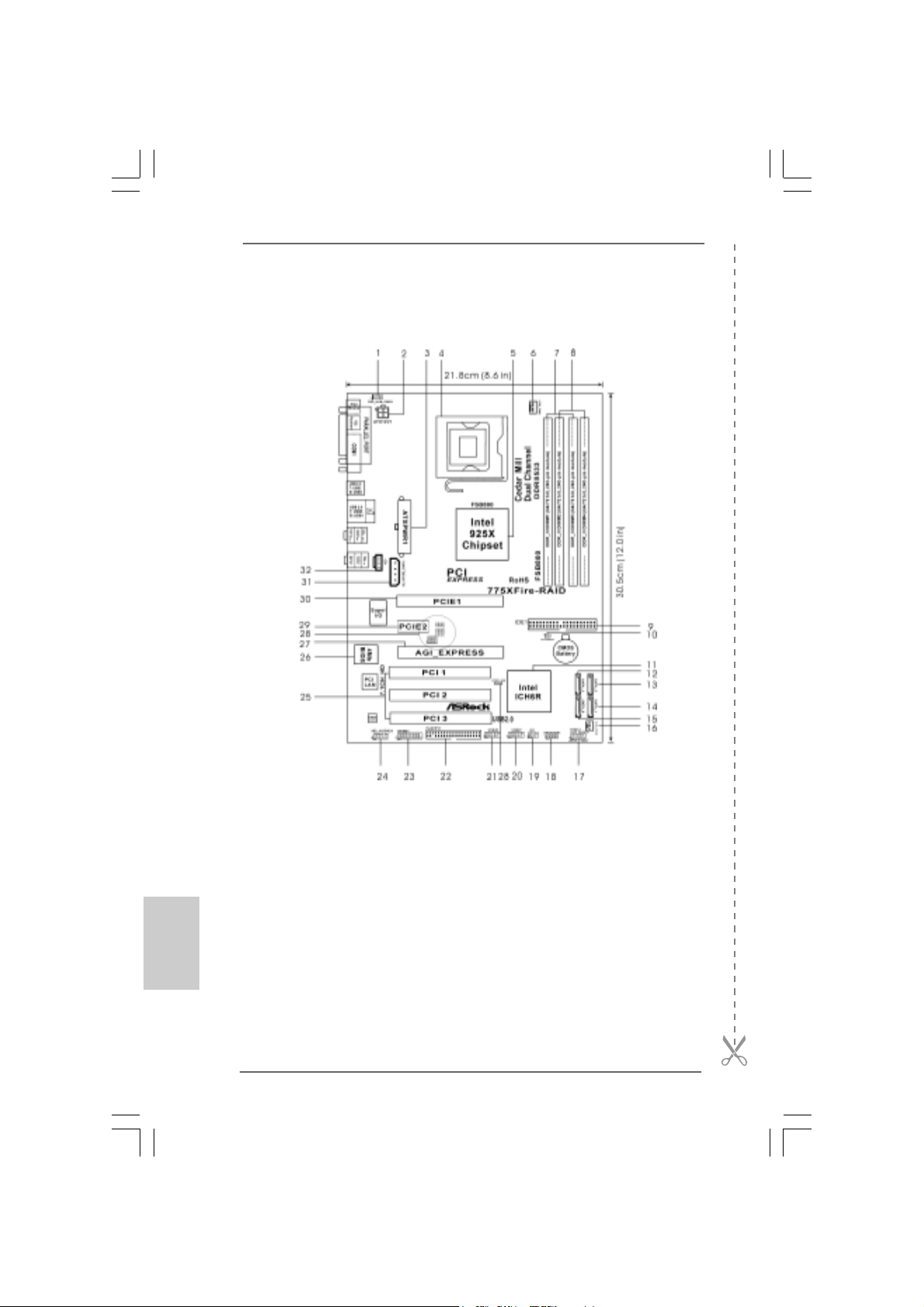
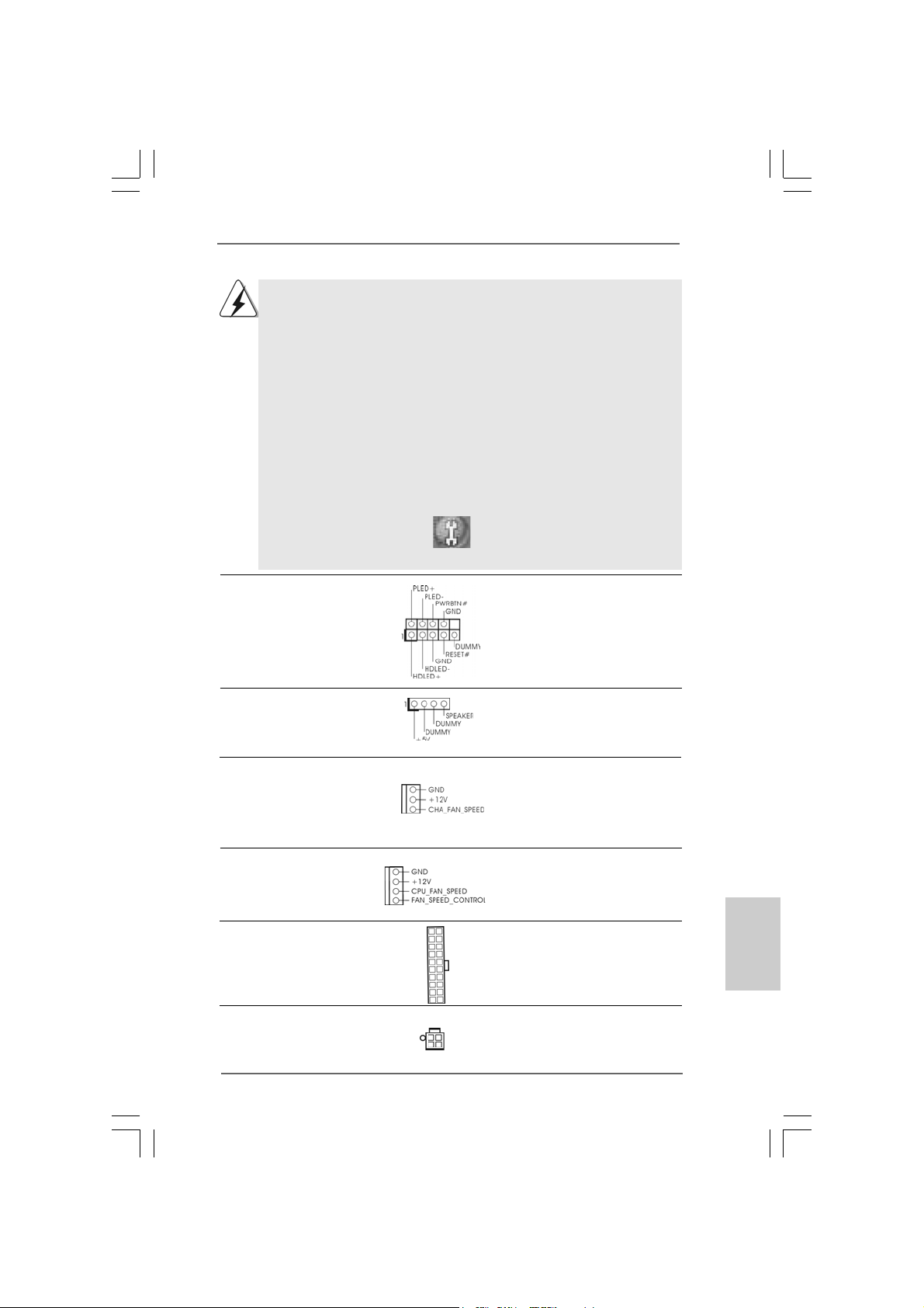
1 PS2_USB_PWR1 Jumper 16 Chassis Fan Connector (CHA_FAN1)
2 A TX 12V Connector (A TX12V1) 17 System Panel Hea der (P ANEL1)
3 A TX Power Connector (A TXPW R1) 18 Chassis Speaker Header (SPEAKER 1)
4 775-Pin CPU Socket 19 Infrared Module Connector (IR1)
5 North Bridge Controller 20 USB 2.0 Header (USB67, Blue)
6 CPU Fan Connector (CPU_FAN1) 21 USB 2.0 Header (USB45, Blue)
7 2 x 240-pin DDRII DIMM Slots 22 Floppy Connector (FLOPPY1)
(Dual Channel A: DDRII_1, DDRII_3; Yellow) 23 Game Port Header (GAME1)
8 2 x 240-pin DDRII DIMM Slots 24 Front Panel Audio Header (HD_AUDIO1)
(Dual Channel B: DDRII_2, DDRII_4; Orange) 25 PCI Slots (PCI1- 3)
9 IDE1 Connector (IDE1, Blue) 26 BIOS FWH Chip
10 Clear CMOS Jumper (CLRCMOS1) 27 AGI Express Slot (PCI Express x 4)
11 South Bridge Controller 28 PCIEX1_EN1 - 5
12 Serial A T A Connector 2 (SA T A_2, bla ck) 29 PCI Express x 1 Slot (PCIE2)
13 Serial A T A Connector 3 (SA T A_3, bla ck) 30 PCI Express x 16 Slot (PCIE1)
14 Serial A TA Connector 1 (SA TA_1, blue) 31 SLI / XFIRE Power Connector
15 Serial A TA Connector 0 (SA TA_0, blue) 32 Internal Audio Connector: CD1 (Black)
ASRock 775XFire-RAID Motherboard
Page 3
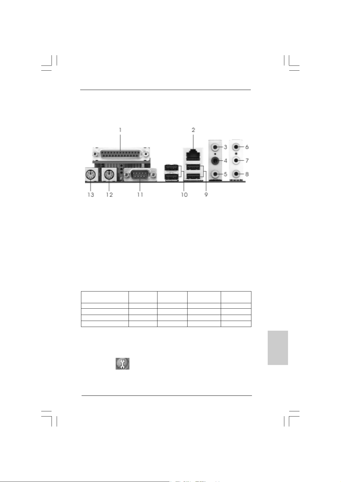
HD 8CH I/OHD 8CH I/O
HD 8CH I/O
HD 8CH I/OHD 8CH I/O
1 Parallel Port 8 Microphone (Pink)
2 RJ-45 Port 9 USB 2.0 Ports (USB01)
3 Side Speaker (Gray) 10 USB 2.0 Ports (USB23)
4 Rear Speaker (Black) 11 Serial Port: COM1
5 Central / Bass (Orange) 12 PS/2 Keyboard Port (Purple)
6 Line In (Light Blue) 13 PS/2 Mouse Port (Green)
*7 Front Speaker (Lime)
* If you use 2-channel spea ker, please connect the speaker’s plug into “Front Speaker Jack”. See
the table below for connection details in accordance with the type of speaker you use.
TABLE for Audio Output Connection
Audio Output Channels Front Speaker Rear Speaker Central / Bass Side Speaker
(No. 7) (No. 4) (No. 5) (No. 3)
2 V -- -- -4VV---6 VVV-8 VVVV
* If you use 8-channel audio and enable Multi-Streaming function, “Side Speaker” will be disabled
. Therefore, only 6-channel audio function will work but not 8-channel audio. To enable Multi Streaming function, you need to connect a front panel audio cable to the front panel audio
header. After restarting your computer, you will find “Mixer” tool on your system. Please select
“Mixer ToolBox” , click “Enable playback multi-streaming”, and click “ok”. Choose
“2CH”, “4CH”, or “6CH”, and then you are allowed to select “Realtek HDA Primary output” to use
Rear Speaker, Central/Bass, and Front Speaker, or select “Realtek HDA Audio 2nd output” to
use front panel audio to share Side Speaker.
ASRock 775XFire-RAID Motherboard
EnglishEnglish
EnglishEnglish
English
33
3
33
Page 4
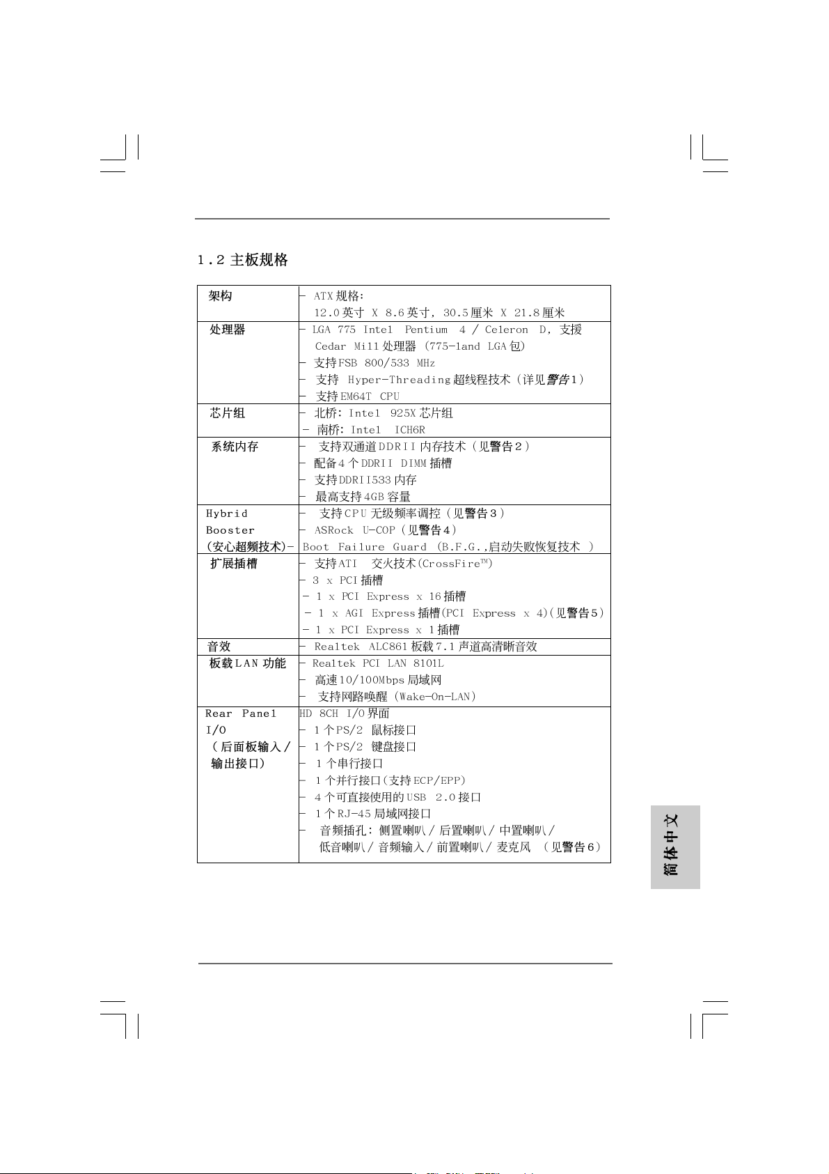
1. Introduction1. Introduction
1. Introduction
1. Introduction1. Introduction
Thank you for purchasing ASRock 775XFire-RAID motherboard, a reli able motherboard
produced under ASRock’s consistently stringent quality control. It delivers excellent
performance with robust design conforming to ASRock’s commitment to quality and
endurance.
This Quick Installation Guide contains introduction of the motherboard and step-bystep installation guide. More detailed information of the motherboard can be found in
the user manual presented in the Support CD.
Because the motherboard specifications and the BIOS software might be
updated, the content of this manual will be subject to change without
notice. In case any modifications of this manual occur, the updated
version will be available on ASRock website without further notice. You
may find the latest VGA cards and CPU support lists on ASRock website
as well. ASRock website
1.1 Package Contents1.1 Package Contents
1.1 Package Contents
1.1 Package Contents1.1 Package Contents
ASRock 775XFire-RAID Motherboard
(ATX Form Factor: 12.0-in x 8.6-in, 30.5 cm x 21.8 cm)
ASRock 775XFire-RAID Quick Installation Guide
ASRock 775XFire-RAID Support CD
(including LGA 775 CPU Installation Live Demo)
One 80-conductor Ultra ATA 66/100 IDE Ribbon Cable
One Ribbon Cable for a 3.5-in Floppy Drive
One Serial ATA (SATA) Data Cable (Optional)
One Serial ATA (SATA) HDD Power Cable (Optional)
One HD 8CH I/O Panel Shield
http://www.asrock.com
English
EnglishEnglish
EnglishEnglish
44
4
44
ASRock 775XFire-RAID Motherboard
Page 5
1.21.2
SpecificationsSpecifications
1.2
Specifications
1.21.2
SpecificationsSpecifications
Platform - ATX Form Factor: 12.0-in x 8.6-in, 30.5 cm x 21.8 cm
CPU - LGA 775 for Intel® Pentium® 4 / Celeron® D, supporting Cedar
Mill processors (in 775-land LGA package)
- FSB 800/533 MHz
- Supports Hyper-Threading Technology (see CAUTION 1)
- Supports EM64T CPU
Chipset - Northbridge: Intel® 925X chipset
- Southbridge: Intel® ICH6R
Memory - Dual Channel DDRII Memory T echnology (see CAUTION 2)
- 4 x DDRII DIMM slots
- Support DDRII533
- Max. capacity: 4GB
Hybrid Booster - CPU Frequency Stepless Control (see CAUTION 3)
- ASRock U-COP (see CAUTION 4)
- Boot Failure Guard (B.F.G.)
Expansion Slot - Supports ATI® CrossFire
- 3 x PCI slots
- 1 x PCI Express x 16 slot
- 1 x AGI Express slot (PCI Express x 4) (see CAUTION 5)
- 1 x PCI Express x 1 slot
Audio - Realtek ALC861 7.1 channel CODEC with High Definition
Audio
LAN - Realtek PCI LAN 8101L
- Speed: 10/100 Ethernet
- Supports Wake-On-LAN
Rear Panel I/O HD 8CH I/O
- 1 x PS/2 Mouse Port
- 1 x PS/2 Keyboard Port
- 1 x Serial Port: COM1
- 1 x Parallel Port (ECP/EPP Support)
- 4 x Ready-to-Use USB 2.0 Ports
- 1 x RJ-45 Port
- Audio Jack: Side Speaker/Rear Speaker/Central Bass/Line
in/Front Speaker/Microphone (see CAUTION 6)
TM
EnglishEnglish
EnglishEnglish
English
ASRock 775XFire-RAID Motherboard
55
5
55
Page 6
Connector - 4 x Serial ATA 1.5Gb/s connectors, support RAID (RAID 0,
RAID 1, and Intel Matrix Storage) and “Hot Plug” functions
- 1 x ATA100 IDE connector (supports 2 x IDE devices)
- 1 x Floppy connector
- 1 x IR header
- 1 x Game header
- CPU/Chassis FAN connector
- 20 pin ATX power connector
- 4 pin 12V power connector
- SLI/XFIRE power connector
- CD in header
- Front panel audio connector
- 2 x USB 2.0 headers (support 4 USB 2.0 ports)
(see CAUTION 7)
BIOS Feature - 4Mb AMI BIOS
- AMI Legal BIOS
- Supports “Plug and Play”
- ACPI 1.1 Compli ance Wa ke Up Events
- Supports jumperfree
Support CD - Drivers, Utilities, AntiVirus Software
Hardware - CPU Temperature Sensing
Monitor - Chassis Temperature Sensing
- CPU Overheat Shutdown to Protect CPU Life
- CPU Fan Ta chometer
- Chassis Fan Tachometer
- CPU Quiet Fan
- Voltage Monitoring: +12V, +5V, +3.3V, Vcore
OS - Microsoft® Windows® 2000/XP/XP 64-bit compliant
Certifications - FCC, CE, WHQL
English
EnglishEnglish
EnglishEnglish
66
6
66
ASRock 775XFire-RAID Motherboard
Page 7

CAUTION!
1. About the setting of “Hyper Threading Technology”, please che ck page 36
of “User Manual” in the Support CD.
2. This motherboard supports Dual Channel Memory Technology . Before you
implement Dual Channel Memory Technology, make sure to read the
installation guide of memory modules on page 12 for proper installation.
3. Although this motherboard offers stepless control, it is not recommended
to perform over-clocking. Frequencies other than the recommended CPU
bus frequencies may cause the instability of the system or damage the
CPU.
4. While CPU overheat is detected, the system will automatically shutdown.
Before you resume the system, please check if the CPU fan on the
motherboard functions properly and unplug the power cord, then plug it
back again. To improve heat dissipation, remember to spray thermal
grease between the CPU a nd the he atsink when you in stall the PC system.
5. If you install PCI Express VGA card to AGI Express slot (PCI Express x
4), PCIE2 slot (PCIE x 1) function will be disabled. For the information of
the compatible PCI Express VGA cards, please refer to the “Supported PCI
Express VGA Card List for AGI Express Slot (PCI Express x 4)” on page
8. For the proper installation of PCI Express VGA card, please refer to the
installation guide on page 14.
6. For microphone input, this motherboard supports both stereo and mono
modes. For audio output, this motherboard supports 2-channel, 4-channel,
6-channel, and 8-channel modes. Please check the table on page 3 for
proper connection.
7. Power Management for USB 2.0 works fine under Microsoft® Windows® XP
SP1 or SP2 / 2000 SP4.
ASRock 775XFire-RAID Motherboard
EnglishEnglish
EnglishEnglish
English
77
7
77
Page 8
1.31.3
Supported PCI Express VGA Card List for AGISupported PCI Express VGA Card List for AGI
1.3
Supported PCI Express VGA Card List for AGI
1.31.3
Supported PCI Express VGA Card List for AGISupported PCI Express VGA Card List for AGI
Express Slot (PCI Express x 4)Express Slot (PCI Express x 4)
Express Slot (PCI Express x 4)
Express Slot (PCI Express x 4)Express Slot (PCI Express x 4)
(for Windows 2000/Windows XP)
Graphics Chip Model Name Chipset Na me
Vendor
NVIDIA
ATI
For the latest updates of the supported PCI Express VGA card list for AGI Express
slot (PCI Express x 4), please visit our website for details.
ASRock website:
Note. It is not recommended to use Turbo cache PCI Express x 16 VGA cards.
ASUS Extreme N6200GE/TD GeForce 6200
ASUS Extreme N6200TC256/TD GeForce 6200
ASUS Extreme N6800/TD GeForce 6800
ASUS Extreme N6800GT GeForce 6800GT
ALBATRON PC6600GT GeForce 6600GT
GIGABYTE GV -NX66128D GeForce 6600
Inno3D GeFORCE 6600 LE GeForce 6600LE
LEADTEK PX6200 TC/TDH GeForce 6200TC
MSI PCX 5750-TD128E GeForce PCX5750
SPARKLE GeFORCE 6200TC GeForce 6200TC
ASUS Extreme AX600XT/HTVD RADEON X600XT
ASUS Extreme AX700PRO/TVD RADEON X700PRO
GECUBE Radeon X850XT 256M RADEON X850XT
MSI RX1300GPRO-TD256E RADEON X1300 PRO
http://www.asrock.com/support/index.htm
English
EnglishEnglish
EnglishEnglish
88
8
88
ASRock 775XFire-RAID Motherboard
Page 9
2.2.
InstallationInstallation
2.
Installation
2.2.
InstallationInstallation
Pre-installation PrecautionsPre-installation Precautions
Pre-installation Precautions
Pre-installation PrecautionsPre-installation Precautions
Take note of the following precautions before you install motherboard components or change any motherboard settings.
1. Unplug the power cord from the wall socket before touching any
component. Failure to do so may cause severe damage to the
motherboard, peripherals, and/or components.
2. To avoid damaging the motherboard components due to static
electricity, NEVER place your motherboard directly on the carpet
or the like. Also remember to use a grounded wrist strap or touch
a safety grounded object before you handle components.
3. Hold components by the edges and do not touch the ICs.
4. Whenever you uninstall any component, place it on a grounded
antstatic pad or in the bag that comes with the component.
5. When placing screws into the screw holes to secure the
motherboard to the chassis, please do not over-tighten the
screws! Doing so may damage the motherboard.
2.12.1
CPU InstallationCPU Installation
2.1
CPU Installation
2.12.1
CPU InstallationCPU Installation
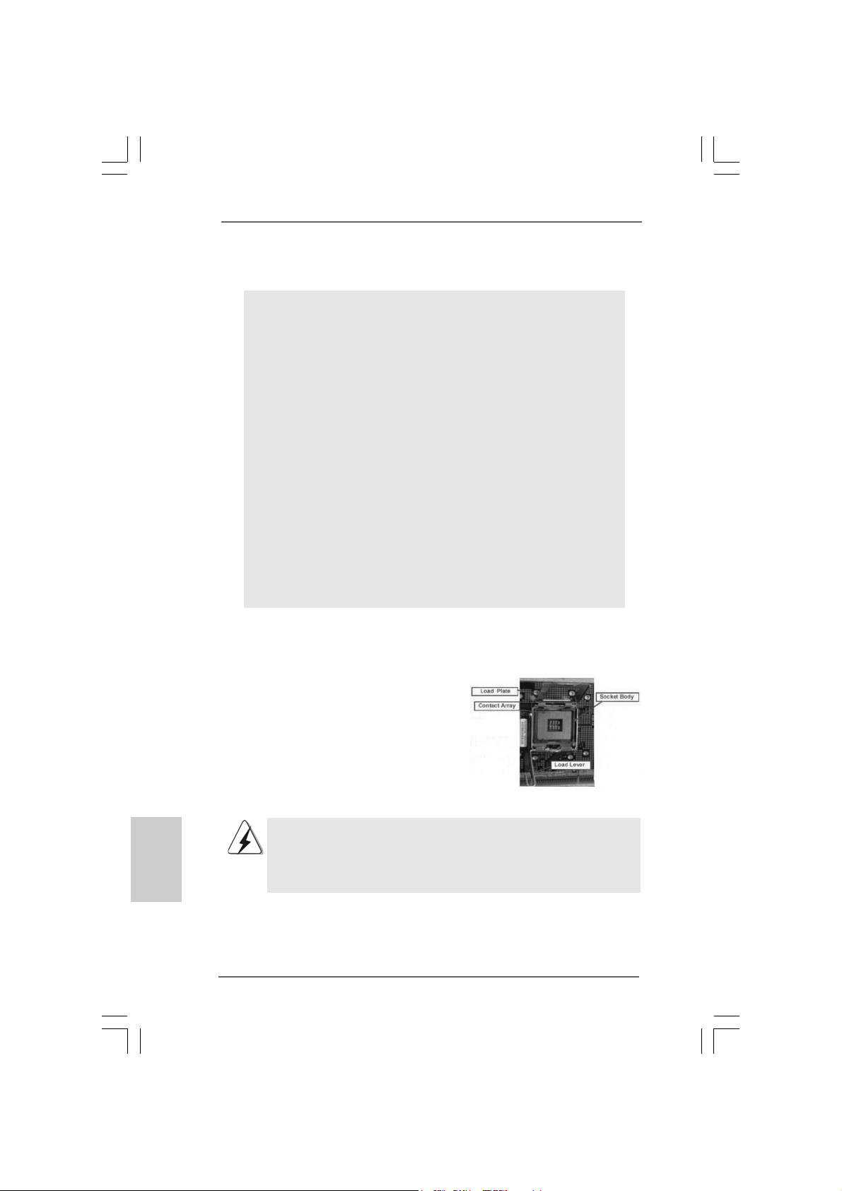
For the installation of Intel 775-LAND CPU,
please follow the steps below.
775-Pin Socket Overview
Before you insert the 775-LAND CPU into the socket, please check if
the CPU surface is unclean or if there is any bent pin on the socket.
Do not force to insert the CPU into the socket if above situation is
found. Otherwise, the CPU will be seriously damaged.
ASRock 775XFire-RAID Motherboard
EnglishEnglish
EnglishEnglish
English
99
9
99
Page 10
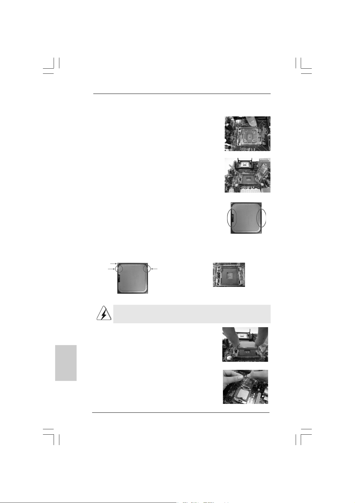
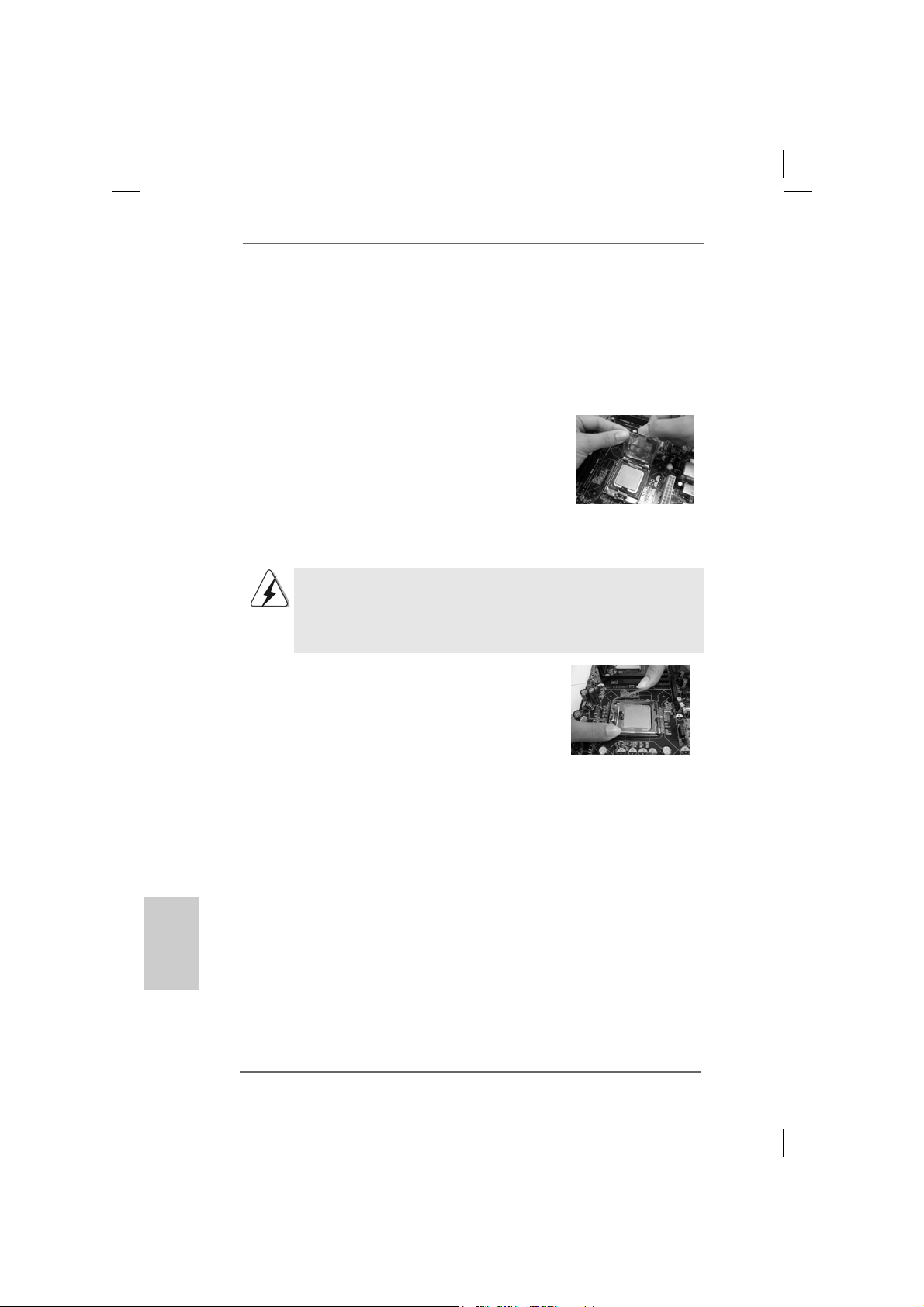
Step 1. Open the socket:
Step 1-1. Disengaging the lever by depressing
down and out on the hook to clear
retention tab.
Step 1-2. Rotate the load lever to fully open po-
sition at approximately 135 degrees.
Step 1-3. Rotate the load plate to fully open po-
sition at approximately 100 degrees.
Step 2. Insert the 775-LAND CPU:
Step 2-1. Hold the CPU by the edges where are
marked with black lines.
Step 2-2. Orient the CPU with IHS (Integrated
Heat Sink) up. Locate Pin1 and the two
orientation key notches.
Pin1
orientation
key notch
orientation
key notch
Pin1
alignment key
black line
black line
alignment key
English
EnglishEnglish
EnglishEnglish
775-LAND CPU
For proper inserting, please ensure to match the two orientation key
notches of the CPU with the two alignment keys of the socket.
Step 2-3. Carefully place the CPU into the socket
by using a purely vertical motion.
Step 2-4. Verify that the CPU is within the socket
and properly mated to the orient keys.
Step 3. Remove PnP Ca p (Pick a nd Place Cap):
Use your left hand index finger and thumb to
support the load plate edge, engage PnP cap
with right hand thumb and peel the cap from the
socket while pressing on center of PnP cap to
assist in removal.
1010
10
1010
ASRock 775XFire-RAID Motherboard
775-Pin Socket
Page 11
1. It is recommended to use the cap tab to handle and avoid kicking
off the PnP cap.
2. This cap must be placed if returning the motherboard for after
service.
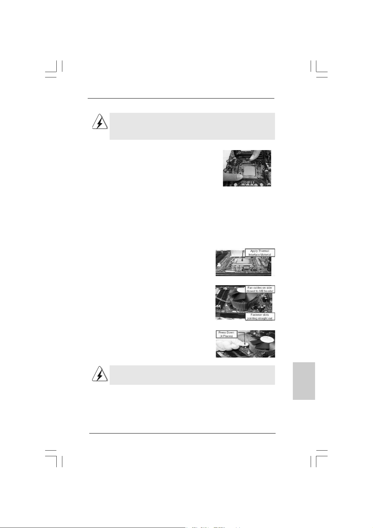
Step 4. Close the socket:
Step 4-1. Rotate the load plate onto the IHS.
Step 4-2. While pressing down lightly on load
plate, engage the load lever.
Step 4-3. Secure load lever with load plate tab
under retention tab of load lever.
2.22.2
Installation of CPU Fan and HeatsinkInstallation of CPU Fan and Heatsink
2.2
Installation of CPU Fan and Heatsink
2.22.2
Installation of CPU Fan and HeatsinkInstallation of CPU Fan and Heatsink
For proper installation, please kindly refer to the instruction manuals of your CPU fan
and heatsink.
Below is an example to illustrate the installation of the heatsink for 775-LAND CPU.
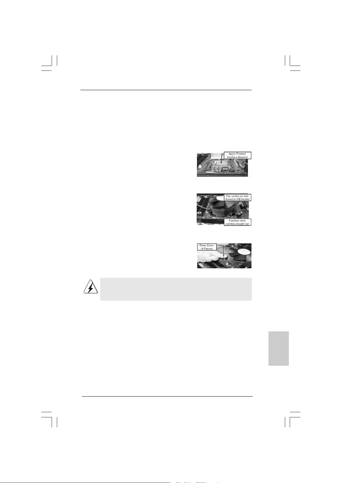
Step 1. Apply thermal interface material onto center
of IHS on the socket surface.
Step 2. Place the heatsink onto the socket. Ensure
fan cables are oriented on side closest to the
CPU fan connector on the motherboard
(CPU_FAN1, see page 2, No. 6).
Step 3. Align fasteners with the motherboard
throughholes.
Step 4. Rotate the fastener clockwise, then press
down on fastener caps with thumb to install
and lock. Repeat with remaining fasteners.
If you press down the fasteners without rotating them clockwise,
the heatsink cannot be secured on the motherboard.
Step 5. Connect fan header with the CPU fan
connector on the motherboard.
Step 6. Secure excess cable with tie-wrap to ensure
cable does not interfere with fan operation or
contact other components.
ASRock 775XFire-RAID Motherboard
1111
11
1111
EnglishEnglish
EnglishEnglish
English
Page 12
2.3 Installation of Memory Modules (DIMM)2.3 Installation of Memory Modules (DIMM)
2.3 Installation of Memory Modules (DIMM)
2.3 Installation of Memory Modules (DIMM)2.3 Installation of Memory Modules (DIMM)
775XFire-RAID motherboard provides four 240-pin DDRII (Double Data Rate II)
DIMM slots, and supports Dual Channel Memory Technology. For dual channel
configuration, you always need to install identical (the same brand, speed,
size and chip-type) DDRII DIMM pair in the slots of the same color. In other words,
you have to install identical DDRII DIMM pair in Dual Channel A (DDRII_1 and
DDRII_3; Yellow slots; see p.2 No.7) or identical DD RII DIMM pair in Dual Chan-
nel B (DDRII_2 and DDRII_4; Orange slots; see p.2 No.8), so that Dual Channel
Memory Technology can be activated. This motherboard also allows you to
install four DDRII DIMMs for dual channel configuration, and please install iden-
tical DDRII DIMMs in all four slots. You may refer to the Dual Channel Memory
Configuration Table below.
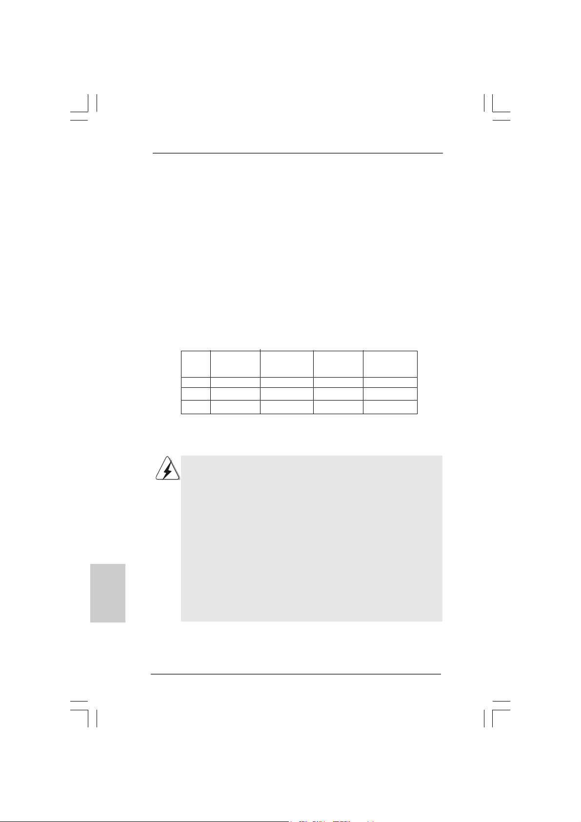
Dual Channel Memory Configurations
DDRII_1 DDRII_2 DDRII_3 DDRII_4
(Yellow Slot) (Orange Slot) (Yellow Slot) (Orange Slot)
(1) Populated - Populated (2) - Populated - Populated
(3)* Populated Populated Populated Populated
* For the configuration (3), please install identical DD RII DIMM s in all four slots.
English
EnglishEnglish
EnglishEnglish
1212
12
1212
1. If you want to install two memory modules, for optimal compatibility
and reliability, it is recommended to install them in the slots of the
same color. In other words, install them either in the set of yellow
slots (DDRII_1 and DDRII_3), or in the set of orange slots (DDRII_2
and DDRII_4).
2. If only one memory module or three memory modules are installed
in the DDRII DIMM slots on this motherboard, it is unable to activate
the Dual Channel Memory T e chnology.
3. If a pair of memory modules is NOT installed in the same Dual
Channel, for exa mple, in stalling a pair of memory module s in D DRII_1
and DDRII_2, it is unable to activate the Dual Channel Memory
Technology .
4. It is not allowed to install a DDR memory module into DDRII slot;
otherwise, this motherboard and DIMM may be damaged.
ASRock 775XFire-RAID Motherboard
Page 13
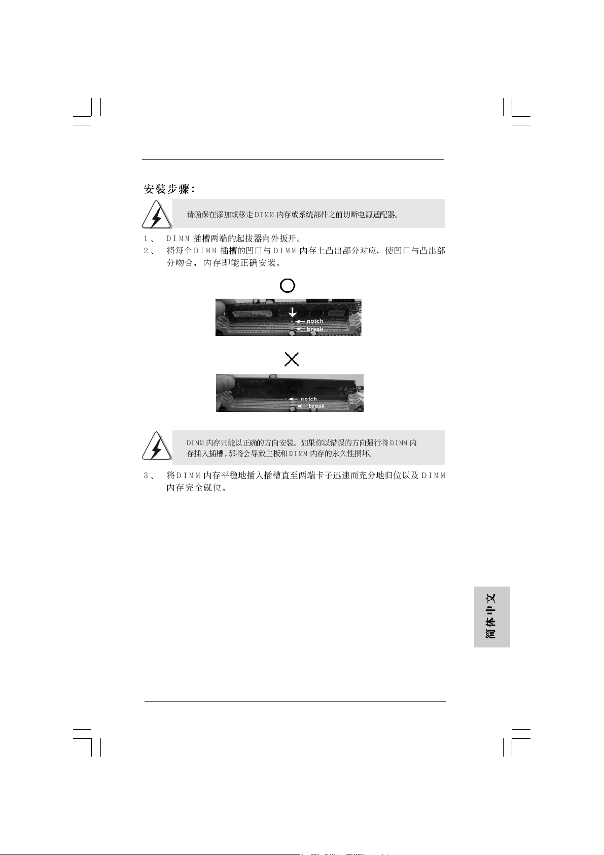
Installing a DIMMInstalling a DIMM
Installing a DIMM
Installing a DIMMInstalling a DIMM
Please make sure to disconnect power supply before adding or
removing DIMMs or the system components.
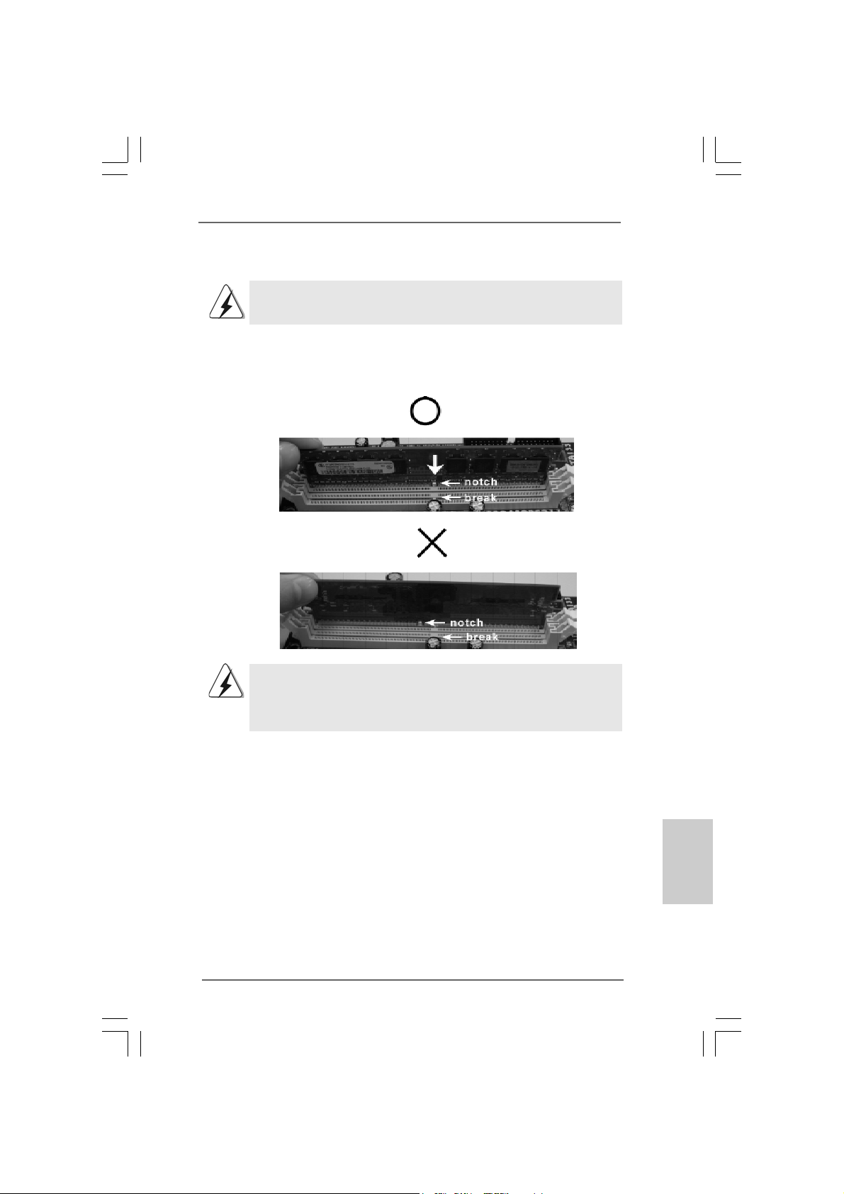
Step 1. Unlock a DIMM slot by pressing the retaining clips outward.
Step 2. Align a DIMM on the slot such that the notch on the DIMM matches the break
on the slot.
The DIMM only fits in one correct orientation. It will cause permanent
damage to the motherboard and the DIMM if you force the DIMM into the
slot at incorrect orientation.
Step 3. Firmly insert the DIMM into the slot until the retaining clips at both ends fully
snap back in place and the DIMM is properly seated.
ASRock 775XFire-RAID Motherboard
1313
13
1313
EnglishEnglish
EnglishEnglish
English
Page 14

2.4 Expansion Slots (PCI, PCI Express, and AGI Express2.4 Expansion Slots (PCI, PCI Express, and AGI Express
2.4 Expansion Slots (PCI, PCI Express, and AGI Express
2.4 Expansion Slots (PCI, PCI Express, and AGI Express2.4 Expansion Slots (PCI, PCI Express, and AGI Express
Slots) Slots)
Slots)
Slots) Slots)
There are 3 PCI slots, 2 PCI Express slots, and 1 AGI Express slot (PCI Express x 4)
on this motherboard.
PCI slots: PCI slots are used to install expansion cards that have the 32-bit PCI
interface.
PCIE Slots: PCIE1 (PCIE x 16 slot) is used for PCI Express cards with x16 lane
width graphics cards.
PCIE2 (PCIE x 1 slot) is used for PCI Express cards, such as
Gigabit LAN card, SATA2 card, etc. Please check the jumper set
tings on page 15 for different functions.
AGI Express slot (PCI Express x 4):
AGI Express slot (PCI Express x 4) is used to install PCI Express expan-
sion cards. For the information of the compatible PCI Express VGA cards,
please refer to the “Supported PCI Express VGA Card List for AGI Ex-
press Slot (PCI Express x 4)” on page 8. Please check the jumper set-
tings on page 15 for different functions.
Installing an expansion cardInstalling an expansion card
Installing an expansion card
Installing an expansion cardInstalling an expansion card
Step 1. Before installing the expansion card, please make sure that the power
supply is switched off or the power cord is unplugged. Please read the
documentation of the expansion card and make necessary hardware
settings for the card before you start the installation.
Step 2. Remove the bracket facing the slot that you intend to use. Keep the screws
for later use.
Step 3. Align the card connector with the slot and press firmly until the card is
completely seated on the slot.
Step 4. Fasten the card to the chassis with screws.
English
EnglishEnglish
EnglishEnglish
1414
14
1414
2.5 Dual Graphics Feature2.5 Dual Graphics Feature
2.5 Dual Graphics Feature
2.5 Dual Graphics Feature2.5 Dual Graphics Feature
This motherboard supports Dual Graphics Technology. When installing the add-on
VGA cards to this motherboard, you are allowed to choose two different ways to
decide the function of PCIE2 slot (PCIE x 1) and AGI Express slot. The default value
of this feature is to enable PCIE2 slot (PCIE x 1) and AGI Express slot (only PCI
Express x 1). You can also adjust the jumpers to disable PCIE2 slot (PCIE x 1). Then
only AGI Express slot (PCI Express x 4) will be enabled. In other words, you are able
to adjust the jumpers to enjoy the benefit of Dual Gra phics fe ature. Please refer to the
table below for the correct jumper settings.
ASRock 775XFire-RAID Motherboard
Page 15
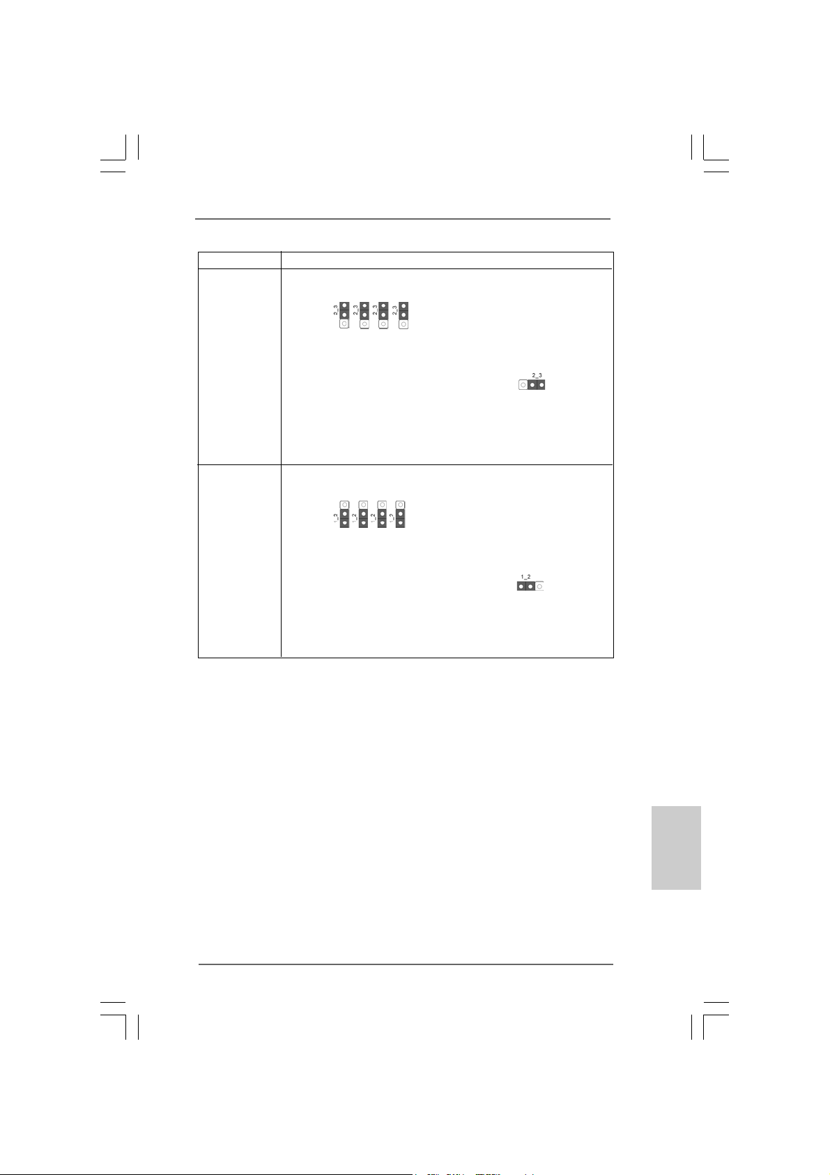
Function Jumper Settings
Enable
PCIE2 /
AGI Express
(only PCIE x 1)
PCIE x 1_EN3
PCIE x 1_EN2
(Default)
PCIE x 1_EN4
PCIE x 1_EN1
Enable
AGI Express
(PCIE x 4)
(Disable PCIE2)
PCIE x 1_EN3
PCIE x 1_EN2
PCIE x 1_EN4
PCIE x 1_EN1
PCIE x 1_EN5
PCIE x 1_EN5
TMTM
TM
2.6 CrossFire2.6 CrossFire
2.6 CrossFire
2.6 CrossFire2.6 CrossFire
TMTM
Operation Guide Operation Guide
Operation Guide
Operation Guide Operation Guide
This motherboard supports CrossFireTM feature. CrossFireTM technology offers the
most advantageous mea n s availa ble of combining multiple high perf ormance Gra phics
Processing Units (GPU) in a single PC. Combining a range of different operating
modes with intelligent software design and an innovative interconnect mechanism,
CrossFireTM enables the highest possible level of performance and image quality in
any 3D application. Currently CrossFireTM feature is only supported with Windows
XP with Service Pack 2; it may be supported with other OS in the future.
ASRock 775XFire-RAID Motherboard
1515
15
1515
EnglishEnglish
EnglishEnglish
English
Page 16
What graphics cards work with CrossFireTM?
A complete CrossFireTM system requires a CrossFireTM Ready motherboard,
a CrossFireTM Edition graphics card and a compatible standard Radeon
(CrossFireTM Ready) graphics card from the same series, or two CrossFire
Ready cards if they are software enabled. This applies to cards from ATI or
any of its partners.
Cards For AGI Express Slot Cards For PCI Express Slot
Radeon X1800 Series Radeon X1800 CrossFireTM Edition
Radeon X1600 Series Radeon X1600 Series
Radeon X1300 Series Radeon X1300 Series
Radeon X850 Series Radeon X850 CrossFireTM Edition
1. If a customer incorrectly configures their system they will not see the
performance benefits of CrossFireTM. All three CrossFireTM components, a
CrossFireTM Ready graphics card, a CrossFireTM Ready motherboard and
a CrossFireTM Edition co-processor graphics card, must be installed
correctly to benefit from the CrossFireTM multi-GPU platform.
2. If you pair a 12-pipe CrossFireTM Edition card with a 16-pipe card, both
cards will operate as 12-pipe cards while in CrossFireTM mode.
Enjoy the benefit of CrossFireEnjoy the benefit of CrossFire
Enjoy the benefit of CrossFire
Enjoy the benefit of CrossFireEnjoy the benefit of CrossFire
TMTM
TM
TMTM
TM
English
EnglishEnglish
EnglishEnglish
1616
16
1616
Currently, ATI has released Radeon X850XT, X1800XT, X1300, and X1600
CrossFireTM cards, which require different methods to enable CrossFire
feature. In the below procedures, we use Radeon X850XT as the example
graphics card. For other CrossFireTM cards that ATI has released or will
release in the future, please refer to ATI graphics card manuals for detailed
installation guide.
TM
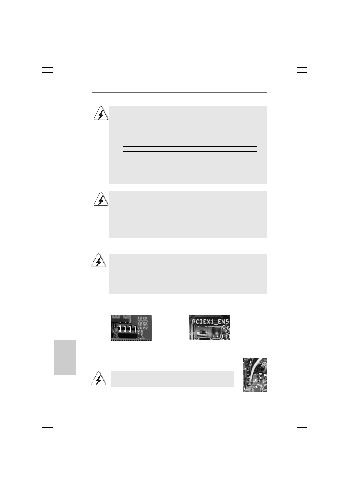
Step 1. Adjust the jumpers on this motherboard to enable AGI Express slot (PCI
Express x 4). Please refer to the pictures below for proper jumper setting.
PCIEx1_EN1-4: Short Pin1, Pin2
PCIEx1_EN5: Short Pin1, Pin2
Step 2. Connect to the system power supply. Please connect a hard
disk power connector to SLI/XFIRE Power connector.
It is recommended to use 500-Watt power supply or greater
to perform the benefit of CrossFireTM feature.
ASRock 775XFire-RAID Motherboard
Page 17
reTM Edition
TM
Edition
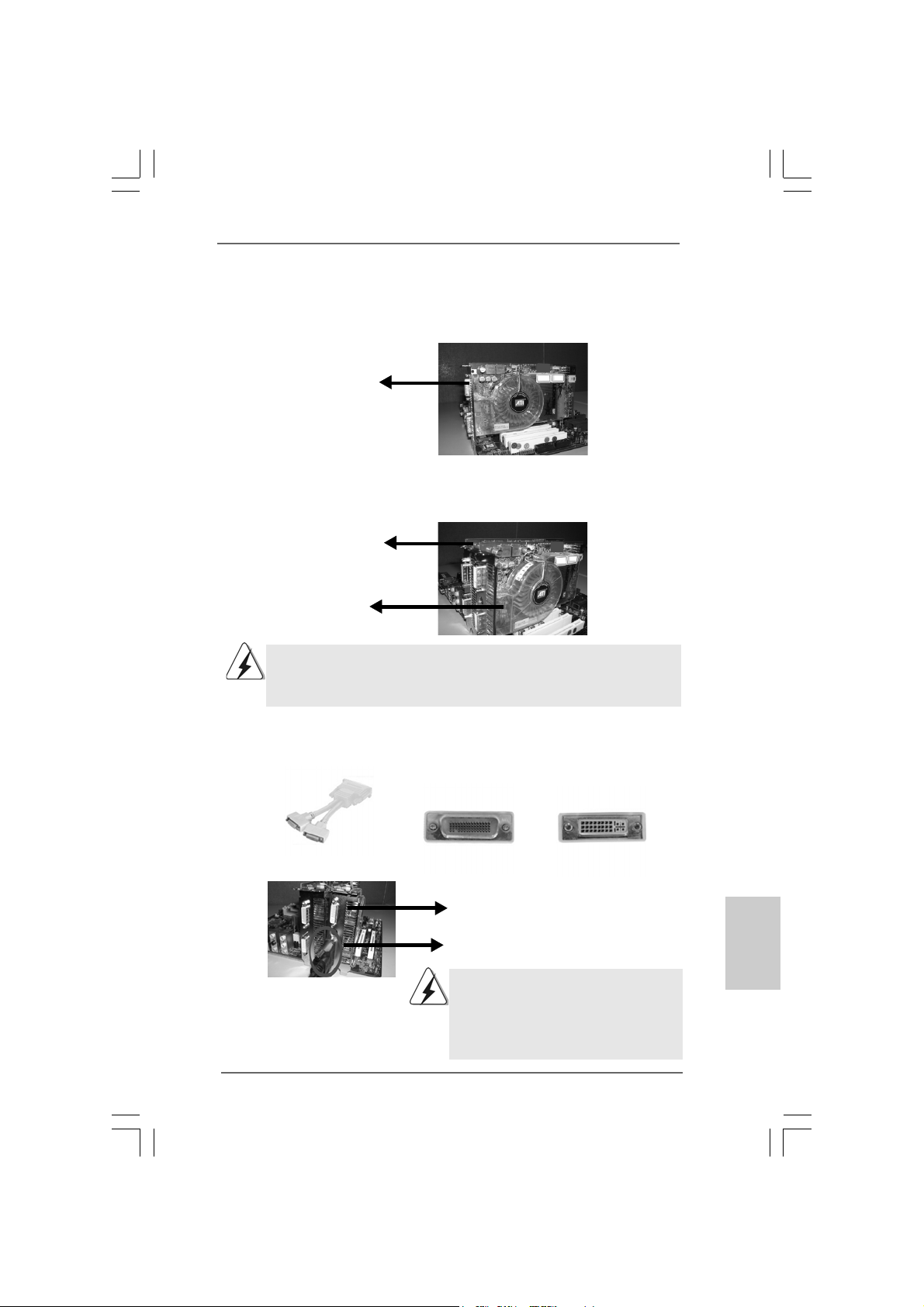
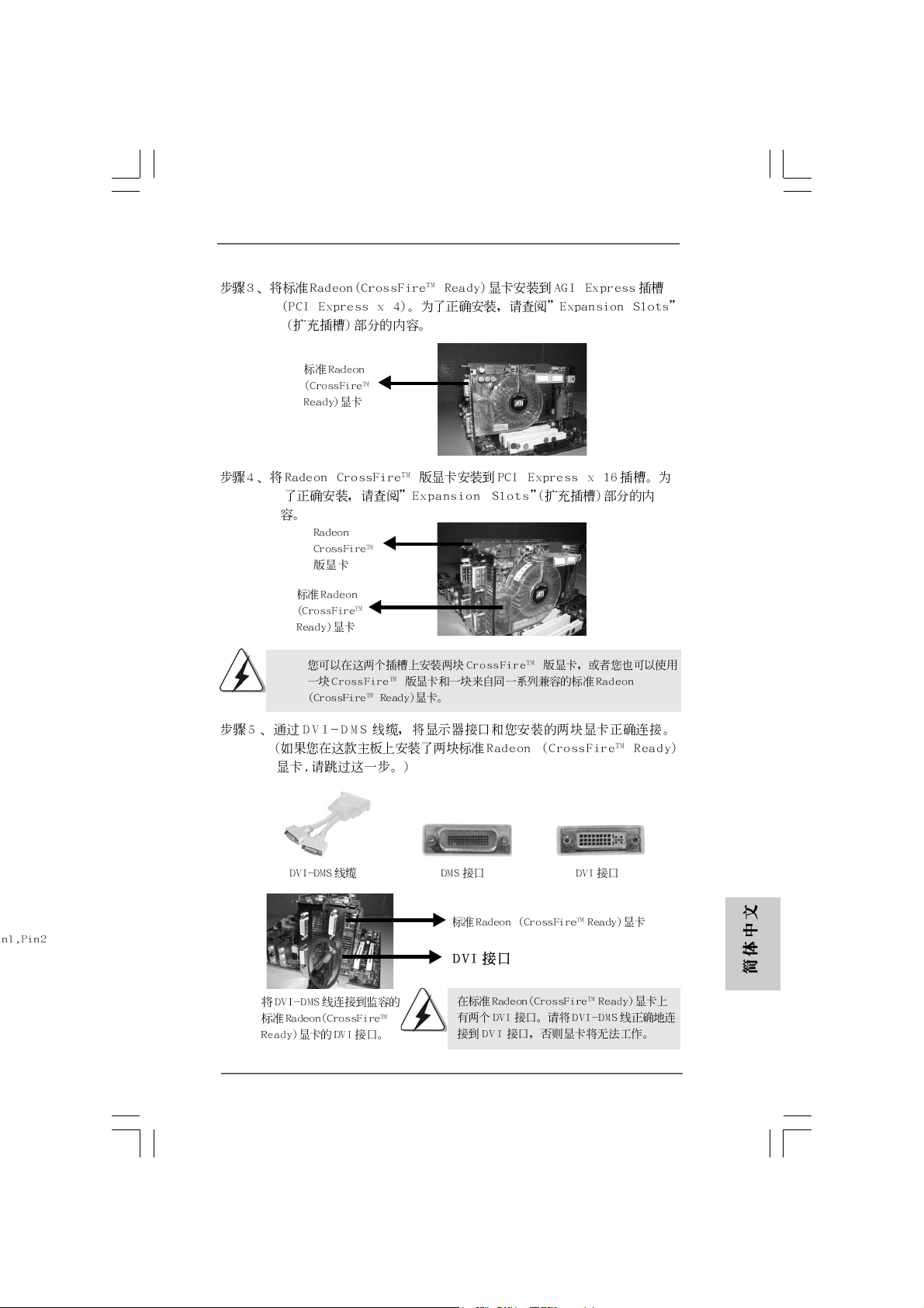
Step 3. Install the standard Radeon (CrossFireTM Ready) graphics card to AGI Ex-
press slot (PCI Express x 4). For the proper installation procedures, please
refer to section “Expansion Slots”.
Standard Radeon
(CrossFireTM Ready)
graphics card
Step 4. Install the Radeon CrossFireTM Edition graphics card to PCI Express x 16
slot. For the proper installation procedures, please refer to section “Expansion Slots”.
1, Pin2
Radeon CrossFire
Edition graphics card
Standard Radeon
(CrossFireTM Ready)
graphics card
You are allowed to install two CrossFireTM Edition graphics cards to both slots,
or you may use one CrossFire
standard Radeon (CrossFireTM Ready) graphics card from the same series.
TM
TM
Edition graphics cards and a compatible
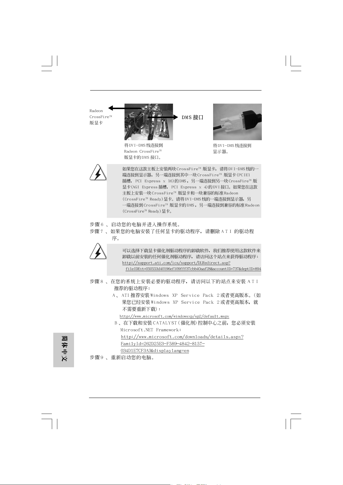
Step 5. Correctly connect the DVI-DMS cable to the monitor connector and two
graphics cards that you install. (If you install two standard Radeon
(CrossFireTM Ready) graphics cards to this motherboard, please skip this
step.)
DVI-DMS cable DMS connector
Standard Radeon (CrossFireTM Ready)
graphics card
DVI connector
D VI connector
Connect the DVI-DMS
cable to DVI connector of
the compatible standard
Radeon (CrossFire
Ready) graphics card.
TM
ASRock 775XFire-RAID Motherboard
There are two DVI connectors on the
standard Radeon (CrossFire
graphics card. Please connect the DVI-DMS
cable to the correct DVI connector; otherwise
, the graphics card will not work.
TM
Ready)
1717
17
1717
EnglishEnglish
EnglishEnglish
English
Page 18
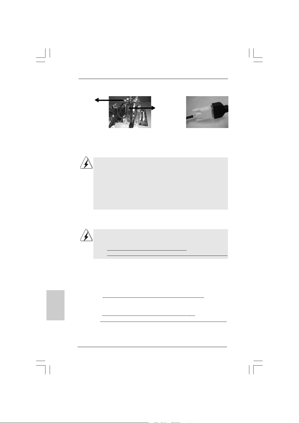
Radeon
CrossFire
Edition graphics
card
TM
DMS
connector
English
EnglishEnglish
EnglishEnglish
Connect the DVI-DMS
cable to DMS connector
of the CrossFire
graphics card.
If you install two CrossFireTM Edition graphics cards to this motherboard, please
connect one end of DVI-DMS cable to the monitor, another end to DMS of one
of the CrossFireTM Edition graphics cards to PCIE1 slot (PCI Express x 16), a n d
the other end to DVI of another CrossFireTM Edition graphics card to AGI
Express slot (PCI Express x 4). If you install one CrossFireTM Edition graphics
card and one compatible standard Radeon (CrossFireTM Ready) graphics card
to this motherboard, please connect one end of DVI-DMS cable to the monitor,
another end to DMS of the CrossFireTM Edition graphics card, a nd the other end
to DVI of the compatible standard Radeon (CrossFireTM Ready) graphics card.
TM
Edition
Connect the DVI-DMS
cable to the monitor
connector.
Step 6. Power on your computer and boot into OS.
Step 7. Remove the ATI driver if you have any VGA driver installed in your system.
The Catalyst Uninstaller is an optional download. We recommend using this
utility to uninstall any previously installed Catalyst drivers prior to installation.
Please visit this website for the driver:
http://support.ati.com/ics/support/DLRedirect.asp?
fileIDExt=050553d40196ef109fff37cbb40aaf28&accountID=737&deptID=894
Step 8. Install the required drivers to your system. Please visit the websites below
for installing the drivers that ATI recommends:
A. ATI recommends Windows XP Service Pack 2 or higher to be installed
(If you have Windows XP Service Pack 2 or higher installed in your
system, there is no need to download it again):
http://www.microsoft.com/windowsxp/sp2/default.mspx
B. You must have Microsoft .NET Framework installed prior to
downloading and installing the CATALYST Control Center:
http://www.microsoft.com/downloads/details.aspx?
FamilyId=262D25E3-F589-4842-8157-034D1E7CF3A3&displaylang=en
Step 9. Restart your computer.
1818
18
1818
ASRock 775XFire-RAID Motherboard
Page 19
Step 10. Install the VGA card drivers to your system, and restart your computer.
Then you will find “ATI Catalyst Control Center” on your desktop (ATI
Catalyst driver should be version 5.10 or higher).
t
t
You will find “ATI Catalyst
Control Center” on your
desktop.
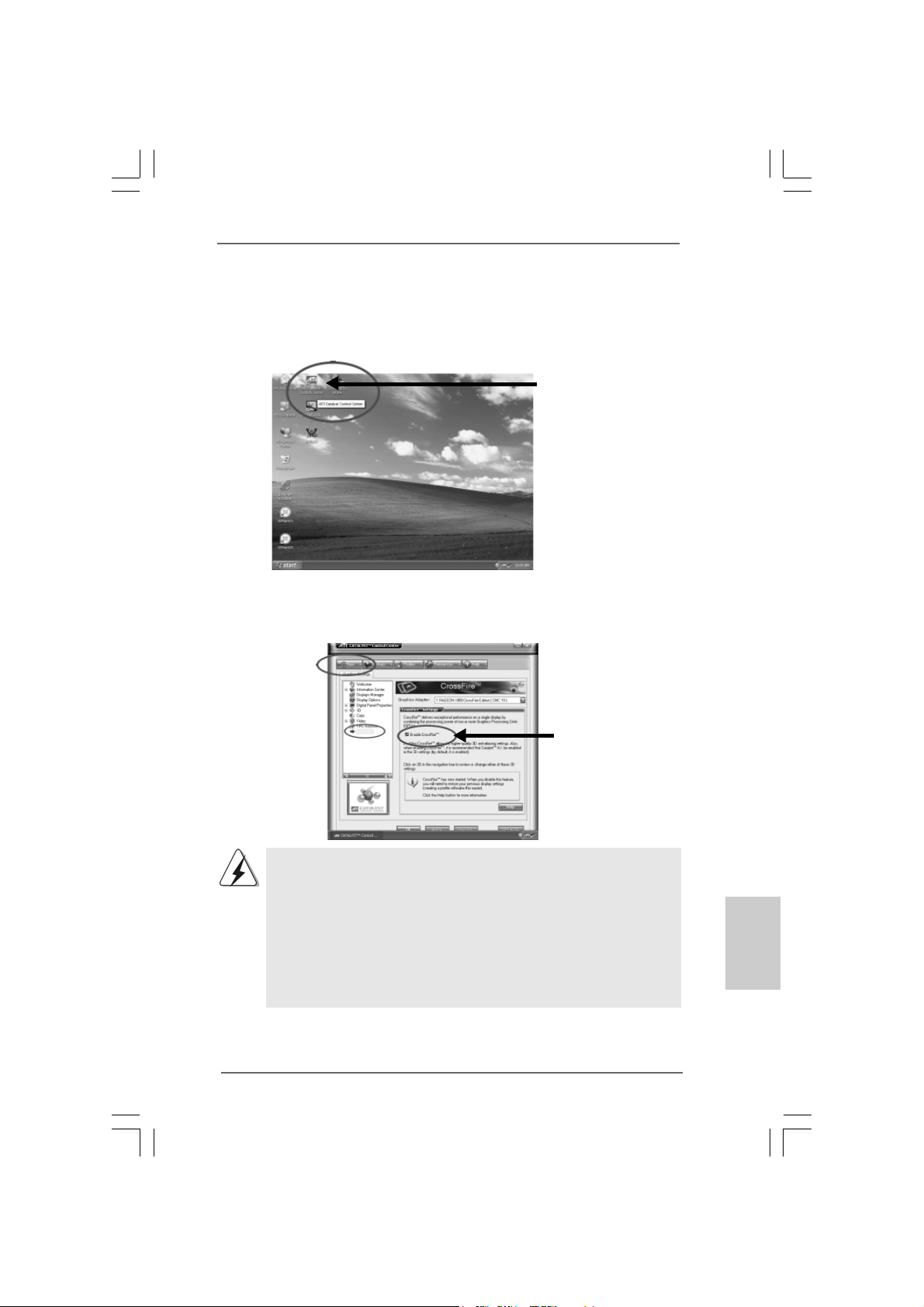
Step 11. Double-click “ATI Catalyst Control Center”. Click “View”, and select “Ad-
vanced View”. Click “CrossFire
TM
”, and then set the option “Enable
CrossFireTM” to “Yes”.
View
CrossFire
TM
Enable CrossFire
TM
If you install one Radeon CrossFireTM Edition graphics card a nd one compatible
standard Radeon (CrossFireTM Ready) graphics card to this motherboard but
not two Radeon CrossFireTM Edition graphics cards, please as well follow the
above steps. However, although you have selected the option “Enable
CrossFireTM”, the CrossFireTM function can not work actually. Your computer
will automatically reboot. After restarting your computer, please confirm whether
the option “Enable CrossFireTM” in “ATI Catalyst Control Center” is selected or
not; if not, please select it again, and then you are able to enjoy the benefit of
CrossFire
TM
feature.
Step 12. You c an freely enjoy the benefit of CrossFireTM feature.
* CrossFireTM appearing here is a registered trademark of ATI Technologies Inc., a nd is used only
for identification or explanation and to the owners’ benefit, without intent to infringe.
ASRock 775XFire-RAID Motherboard
1919
19
1919
EnglishEnglish
EnglishEnglish
English
Page 20
2.7 Surround Display Feature2.7 Surround Display Feature
2.7 Surround Display Feature
2.7 Surround Display Feature2.7 Surround Display Feature
This motherboard supports Surround Display upgrade. With the external add-on
PCI Express VGA card, you can easily enjoy the benefits of Surround Display
feature. For the detailed instruction, please refer to the document at the following
path in the Support CD:
..\ Surround Display Information
2.8 Jumpers Setup2.8 Jumpers Setup
2.8 Jumpers Setup
2.8 Jumpers Setup2.8 Jumpers Setup
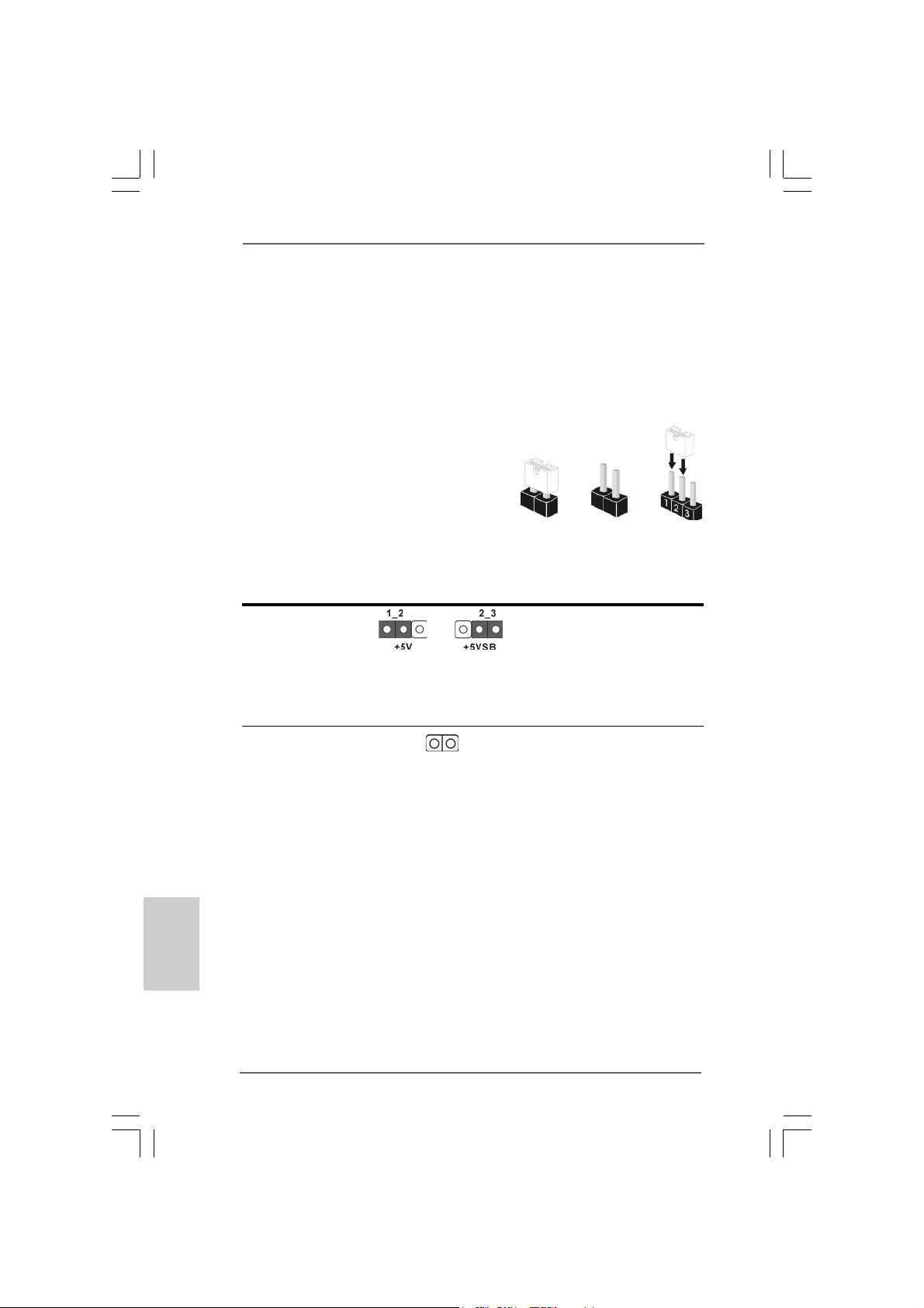
The illustration shows how jumpers are
setup. When the jumper cap is placed on
pins, the jumper is “Short”. If no jumper cap
is placed on pins, the jumper is “Open”. The
illustration shows a 3-pin jumper whose pin1
and pin2 are “Short” when jumper cap is
placed on these 2 pins.
Jumper Setting Description
PS2_USB_PWR1 Short pin2, pin3 to enable
(see p.2 No. 1) +5VSB (standby) for PS/2
Note: To select +5VSB, it requires 2 Amp and higher standby current provided by
power supply.
Short Open
or USB wake up events.
English
EnglishEnglish
EnglishEnglish
2020
20
2020
Clear CMOS
(CLRCMOS1, 2-pin jumper)
(see p.2 No. 10)
Note: CLRCMOS1 allows you to clear the data in CMOS. The data in CMOS includes
system setup information such as system password, date, time, and system
setup parameters. To clear and reset the system parameters to default setup,
please turn off the computer and unplug the power cord from the power
supply. After waiting for 15 seconds, use a jumper cap to short 2 pins on
CLRCMOS1 for 5 seconds.
ASRock 775XFire-RAID Motherboard
2-pin jumper
Page 21
2.9 Onboard Headers and Connectors2.9 Onboard Headers and Connectors
2.9 Onboard Headers and Connectors
2.9 Onboard Headers and Connectors2.9 Onboard Headers and Connectors
Onboard headers and connectors are NOT jumpers. Do NOT place
jumper caps over these headers and connectors. Placing jumper caps
over the headers and connectors will cause permanent damage of the
motherboard!
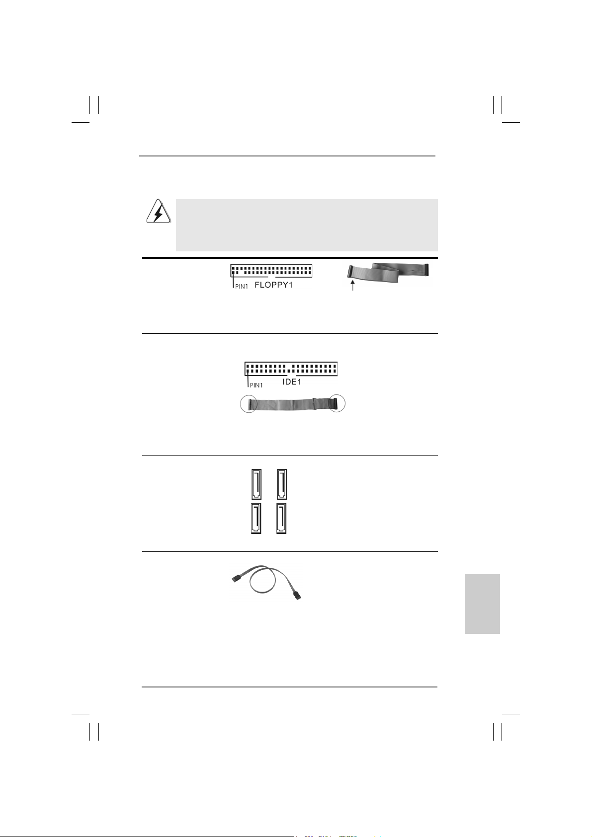
FDD connector
(33-pin FLOPPY1)
(see p.2 No. 22)
the red-striped side to Pin1
Note: Make sure the red-striped side of the cable is plugged into Pin1 side of the
connector.
Primary IDE connector (Blue)
(39-pin IDE1, see p.2 No. 9)
connect the blue end
to the motherboard
connect the black end
to the IDE devices
80-conductor ATA 66/100 cable
Note: Please refer to the instruction of your IDE device vendor for the details.
Serial A TAI Connectors These four Serial AT A
(SAT A_0: see p.2, No. 15) (SATA) connectors support
(SAT A_1: see p.2, No. 14) SATA data cables for internal
(SAT A_2: see p.2, No. 12) storage devices. The current
(SAT A_3: see p.2, No. 13) SATA interface allows up to
SATA_2
SATA_0
SATA_3
SATA_1
1.5 Gb/s data transfer rate.
Serial A TA (SATA) Either end of the SATA data ca ble
Data Cable can be connected to the SATA
hard disk or the SA TA conne ctor
on the motherboard.
EnglishEnglish
EnglishEnglish
English
ASRock 775XFire-RAID Motherboard
2121
21
2121
Page 22
Serial ATA (SATA) Please connect the black end of
Power Cable SATA power cable to the power
(Optional) connector on each drive. Then
connect to the SAT A
HDD power connector
connect to the
power supply
connect the white end of SATA
power cable to the power
connector of the power supply.
USB 2.0 Header HD 8CH I/O accommo-
(9-pin USB67) dates 4 default USB 2.0 ports. If
(see p.2 No. 20) those USB 2.0 ports on the I/O
panel are not sufficient, this
USB 2.0 header is available to
support 2 additional USB 2.0
ports.
USB 2.0 Header HD 8CH I/O accommo-
(9-pin USB45) dates 4 default USB 2.0 ports. If
(see p.2 No. 21) those USB 2.0 ports on the I/O
panel are not sufficient, this
USB 2.0 header is available to
support 2 additional USB 2.0
ports.
Infrared Module Header This header supports an
(5-pin IR1) optional wireless transmitting
(see p.2 No. 19) and receiving infrared module.
English
EnglishEnglish
EnglishEnglish
2222
22
2222
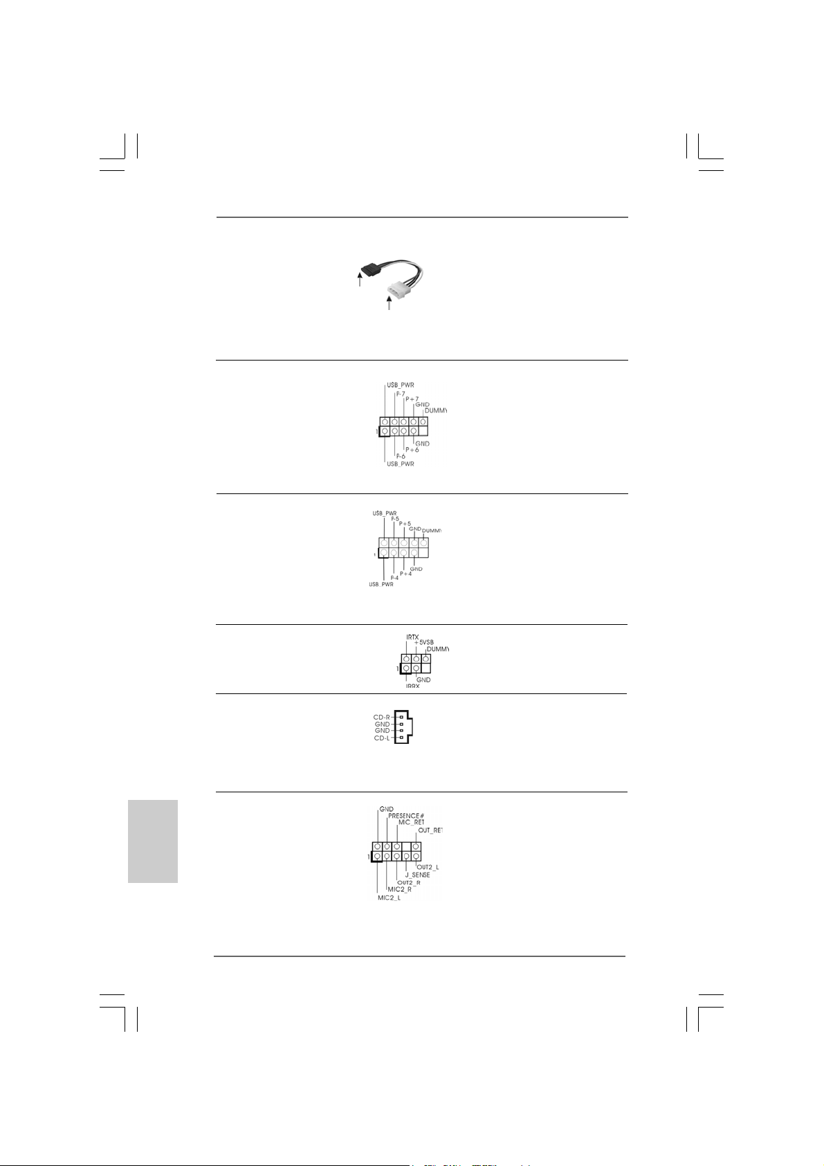
Internal Audio Connectors Thise connector allows you
(4-pin CD1) to receive stereo audio input
(CD1: see p.2 No. 32) from sound sources such as
CD1
a CD-ROM, D VD-ROM, TV
tuner card, or MPEG card.
Front Panel Audio Header This is an interface for front
(9-pin HD_AUDIO1) panel audio cable that allows
(see p.2 No. 24) convenient connection and
control of audio devices.
ASRock 775XFire-RAID Motherboard
Page 23
1. High Definition Audio supports Jack Sensing, but the panel wire on the
chassis must support HDA to function correctly. Please follow the
instruction in our manual and chassis manual to install your system.
2. If you use AC’97 audio panel, please install it to the front panel audio
header as below:
A. Connect Mic_IN (MIC) to MIC2_L.
B. Connect Audio_R (RIN) to OUT2_R and Audio_L (LIN) to OUT2_L.
C. MIC_RET and OUT_RET are for HD audio panel only. You don’t
need to connect them for AC’97 audio panel.
D. Enter BIOS Setup Utility. Enter Advanced Settings, and then select
Chipset Configuration. Set the Front Panel Control option from
[Auto] to [Enabled].
E. Enter Windows system. Click the icon on the lower right hand
taskbar to enter Realtek HD Audio Manager. Click “Audio I/O”, select
“Connector Settings” , choose “Disable front panel jack
detection”, and save the change by clicking “OK”.
System Panel Header This header accommodates
(9-pin PANEL1) several system front panel
(see p.2 No. 17) functions.
Chassis Speaker Header Please connect the chassis
(4-pin SPEAKER 1) speaker to this header.
(see p.2 No. 18)
Chassis Fan Connector Please connect a chassis fan
(3-pin CHA_FAN1) cable to this connector and
(see p.2 No. 16) match the black wire to the
ground pin.
CPU Fan Connector Please connect a CPU fan cable
(4-pin CPU_FAN1) to this connector and match
(see p.2 No. 6) the black wire to the ground pin.
ATX Power Connector Please connect an ATX power
(20-pin ATXPW R1) supply to this connector.
(see p.2 No. 3)
ATX 12V Connector Please connect an ATX 12V
(4-pin A TX12V1) power supply to this connector.
(see p.2 No. 2)
ASRock 775XFire-RAID Motherboard
2323
23
2323
EnglishEnglish
EnglishEnglish
English
Page 24
SLI/XFIRE Power Connector It is not necessary to use this
(4-pin SLI/XFIRE_POWER1) connector, but please connect it
(see p.2 No. 31) with a hard disk power connecor
SLI/XFIRE_POWER1
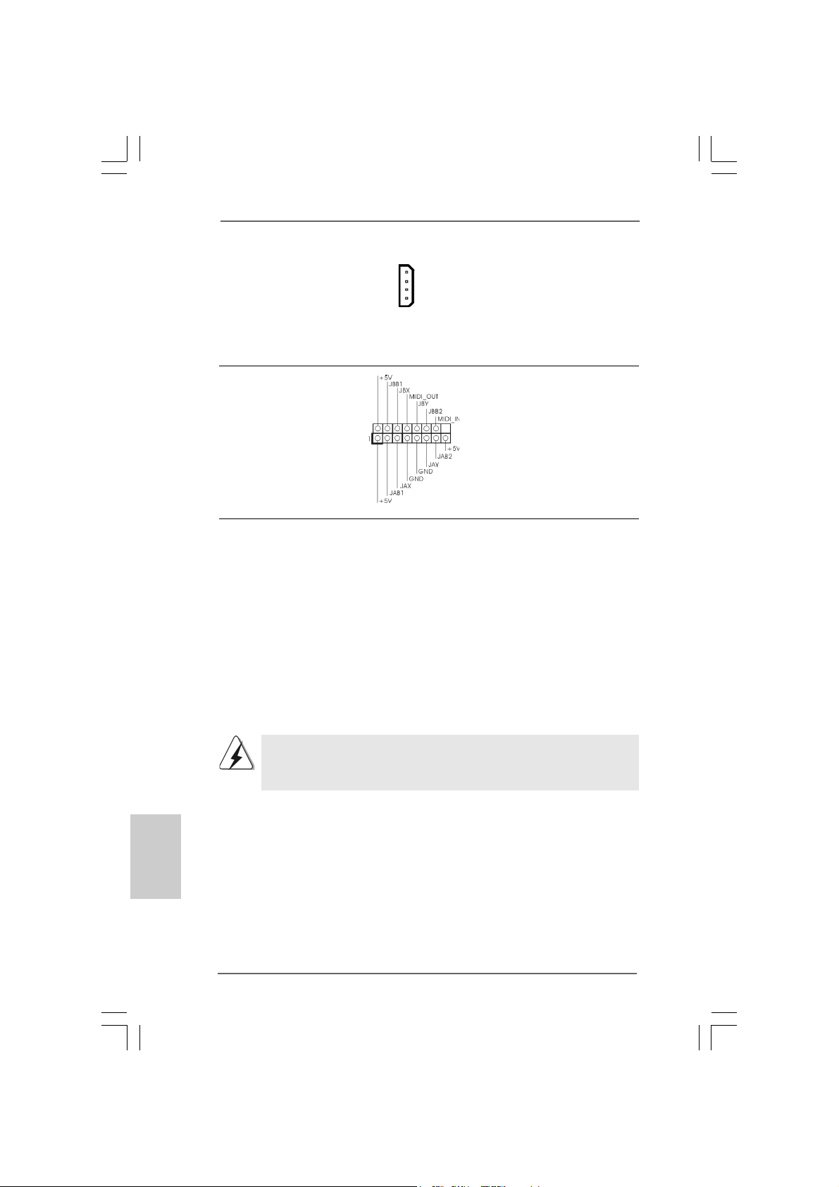
Game Port Hea der Connect a Game cable to this
(15-pin GAME1) header if the Game port bracket
(see p.2 No. 23) is installed.
2.102.10
Serial ASerial A
2.10
Serial A
2.102.10
Serial ASerial A
This motherboard adopts Intel ICH6R south bridge chipset that supports Serial ATA
(SATA) hard disks and RAID (RAID 0, RAID 1, and Intel Matrix Storage) functions.
You may install SATA hard disks on this motherboard for internal storage devices.
This section will guide you to install the SATA hard disks.
STEP 1: Install the SATA hard disks into the drive bays of your chassis.
STEP 2: Connect the SATA power cable to the SATA hard disk.
STEP 3: Connect one end of the SATA data cable to the motherboard’s SATA
connector.
STEP 4: Connect the other end of the SATA data cable to the SATA hard disk.
TT
A (SAA (SA
T
A (SA
TT
A (SAA (SA
TT
A) Hard Disks InstallationA) Hard Disks Installation
T
A) Hard Disks Installation
TT
A) Hard Disks InstallationA) Hard Disks Installation
when two graphics cards are
plugged to this motherboard at
the same ti me.
English
EnglishEnglish
EnglishEnglish
2424
24
2424
It is not recommended to switch the “Configure SATA as” setting between
AHCI, RAID, and IDE mode after OS installation.
ASRock 775XFire-RAID Motherboard
Page 25
2.11 Hot Plug and Hot Swap F2.11 Hot Plug and Hot Swap F
2.11 Hot Plug and Hot Swap F
2.11 Hot Plug and Hot Swap F2.11 Hot Plug and Hot Swap F
775XFire-RAID motherboard supports Hot Plug and Hot Swap functions
for SATA Devices.
NOTE
What is Hot Plug Function?
If the SATA HDDs are NOT set for RAID configuration, it is called “Hot
Plug” for the action to insert and remove the SATA HDDs while the system
is still power-on and in working condition.
However, please note that it cannot perform Hot Plug if the OS has been
installed into the SATA HDD.
What is Hot Swap Function?
If SATA HDDs are built as RAID1 then it is called “Hot Swap” for the action
to insert and remove the SATA HDDs while the system is still power-on
and in working condition.
unctions for SAunctions for SA
unctions for SA
unctions for SAunctions for SA
TT
T
TT
A HDDsA HDDs
A HDDs
A HDDsA HDDs
ASRock 775XFire-RAID Motherboard
2525
25
2525
EnglishEnglish
EnglishEnglish
English
Page 26

English
EnglishEnglish
EnglishEnglish
2.122.12
Installing Windows 2000 / Windows XP /Installing Windows 2000 / Windows XP /
2.12
Installing Windows 2000 / Windows XP /
2.122.12
Installing Windows 2000 / Windows XP /Installing Windows 2000 / Windows XP /
Windows XP 64-bit With RAID FunctionsWindows XP 64-bit With RAID Functions
Windows XP 64-bit With RAID Functions
Windows XP 64-bit With RAID FunctionsWindows XP 64-bit With RAID Functions
If you want to install Windows 2000 / Windows XP / Windows XP-64bit OS on your
SATA HDDs with RAID functions, please follow the below steps.
STEP 1: Set up BIOS.
A. Enter BIOS SETUP UTILITY Advanced screen IDE Configuration.
B. Set “ATA/IDE Configuration” to [Enhanced], and then in the option “Configure
SATA as”, please set the option to [RAID].
STEP 2: Make a SATA Driver Diskette.
A. Insert the Support CD into your optical drive to boot your system.
B. During POST at the beginning of system boot-up, press <F11> key, and then a
window for boot devices selection appears. Please select CD-ROM as the boot
device.
C. When you see the message on the screen, “Do you want to generate Serial
ATA driver diskette [YN]?”, press <Y>.
D. Then you will see these messages,
Please insert a diskette into the floppy drive.
WARNING! Formatting the floppy diskette will
lose ALL data in it!
Start to format and copy files [YN]?
Please insert a floppy diskette into the floppy drive, and press <Y>.
E. The system will start to format the floppy diskette and copy SATA drivers into
the floppy diskette.
STEP 3: Use “RAID Installation Guide” to set RAID configuration.
Before you start to configure the RAID function, you need to check the installation
guide in the Support CD for proper configuration. Please refer to the document in the
Support CD, “Guide to SATA Hard Disks Installation and RAID Configuration”, which is
located in the folder at the following path: .. \ RAID Installation Guide
STEP 4: Install Windows 2000 / Windows XP / Windows XP 64-bit OS on
your system.
After making a SATA driver diskette and using “RAID Installation Guide” to set RAID
configuration, you can start to install Windows 2000 / Windows XP / Windows XP
64-bit on your system. At the beginning of Windows setup, press F6 to install a thirdparty SCSI or RAID driver. When prompted, insert a floppy disk containing the Intel
RAID driver. After reading the floppy disk, the driver will be presented. Select the
driver to install according to the mode you choose and the OS you install. You
may select: “Intel(R) 82801FR SATA RAID Controller (Desktop ICH6R-Windows XP/
2000)” for Windows XP/2000 or “Intel(R) 82801FR SATA RAID Controller (Desktop
ICH6R-Windows XP64)” for Windows XP 64-bit.
2626
26
2626
ASRock 775XFire-RAID Motherboard
Page 27
After the installation of Windows 2000 / Windows XP / Windows XP 64-bit OS, if you want to
manage RAID functions, you are allowed to use both “RAID Installation Guide” and “Intel
Matrix Storage Manager Information” for RAID configuration. Please refer to the document
in the Support CD, “Guide to SATA Hard Disks Installation and RAID Configuration”, which
is located in the folder at the following path: .. \ RAID Installation Guide and the document
in the support CD, “Guide to Intel Matrix Storage Manager”, which is located in the folder at
the following path: .. \ Intel Matrix Storage Manager Information
If you want to use “Intel Matrix Storage Manager” in Windows environment,
please install SATA drivers from the Support CD again so that “Intel Matrix
Storage Manager” will be installed to your system as well.
2.12.1 Setting Up a “RAID Ready” System2.12.1 Setting Up a “RAID Ready” System
2.12.1 Setting Up a “RAID Ready” System
2.12.1 Setting Up a “RAID Ready” System2.12.1 Setting Up a “RAID Ready” System
You can also set up a “RAID Ready” system with a single SATA hard disk. A “RAID
Ready” system can be seamlessly upgraded to RAID 0 or RAID 1 at a later date by
using RAID migration feature of Intel Matrix Storage. The following steps outline
how to build an Intel “RAID Ready” system.
1. Assemble the system and attach a single SATA hard drive.
2. Set up system BIOS as step 1 of page 26. When done, exit Setup.
3. Make a SATA driver diskette as step 2 of page 26. Begin Windows setup by
booting from the installation CD.
4. At the beginning of Windows setup, press F6 to install a third-party SCSI or
RAID driver. When prompted, insert a floppy disk containing the Intel RAID
driver. After reading the floppy disk, the driver will be presented. Select the
driver to install according to the mode you choose and the OS you install. You
may select: “Intel(R) 82801FR SATA RAID Controller (Desktop ICH6R-Windows
XP/2000)” for Windows XP/2000 or “Intel(R) 82801FR SATA RAID Controller
(Desktop ICH6R-Windows XP64)” for Windows XP 64-bit.
5. Finish the Windows installation and install all necessary drivers.
6. Install the Intel(R) Matrix Storage Manager software via the CD-ROM included
with your motherboard or after downloading it from the Internet. This will add
the Intel(R) Matrix Storage Console which can be used to manage the RAID
configuration.
7. After setting up a “RAID Ready” system as the above steps, you can follow the
procedures of the next section to migrate the system to RAID 0 or RAID 1.
2.12.2 Migrating a “RAID Ready” System to RAID 0 or2.12.2 Migrating a “RAID Ready” System to RAID 0 or
2.12.2 Migrating a “RAID Ready” System to RAID 0 or
2.12.2 Migrating a “RAID Ready” System to RAID 0 or2.12.2 Migrating a “RAID Ready” System to RAID 0 or
RAID 1 RAID 1
RAID 1
RAID 1 RAID 1
If you have an existing “RAID Ready” system, then you can use the following
steps to perform a migration from a single non-RAID configuration to a two drive
RAID 0 or RAID 1 configuration. To prepare for this, you will need another SATA
hard drive with a capacity equal to or greater than that currently being used as the
source hard drive.
ASRock 775XFire-RAID Motherboard
2727
27
2727
EnglishEnglish
EnglishEnglish
English
Page 28
English
EnglishEnglish
EnglishEnglish
2828
28
2828
1. Physically attach one additional SATA hard drive to the SATA port not being
used. Note the serial number of the hard drive already in the system; you will
use this to select it as the source hard drive when initiating the migration.
2. Boot Windows, install the Intel(R) Matrix Storage Manager software, if not
already installed, using the setup package obtained from a CD-ROM or from the
Internet. This will install the necessary Intel Storage Utility and start menu links.
3. Open the Intel Storage Utility from the Start Menu and select “Create RAID
volume from Existing Hard Drive” from the Actions menu. This will activate the
Create RAID volume from Existing Hard Drive Wizard. Click through the dialogs
as prompted. It’s important to understand what will occur during the migration
process because any data on the destination hard drive will be lost.
4. Once the migration is complete, reboot the system. If you migrated to a RAID 0
volume, use Disk Management from within Windows in order to partition and
format the empty space created when the two hard drive capacities are
combined. You may also use third-party software to extend any existing
partitions within the RAID volume.
2.132.13
Installing Windows 2000 / XP / XP 64-bit WithoutInstalling Windows 2000 / XP / XP 64-bit Without
2.13
Installing Windows 2000 / XP / XP 64-bit Without
2.132.13
Installing Windows 2000 / XP / XP 64-bit WithoutInstalling Windows 2000 / XP / XP 64-bit Without
RAID FunctionsRAID Functions
RAID Functions
RAID FunctionsRAID Functions
If you want to install Windows 2000 / XP / XP 64-bit on your SAT A HDDs without RAID
functions, please follow the below steps.
STEP 1: Set Up BIOS.
A. Enter BIOS SETUP UTILITY Advanced screen IDE Configuration.
B. Set “ATA/IDE Configuration” to [Enhanced], and then in the option “Configure
SATA as”, please set the option to [AHCI] or [IDE].
STEP 2: Make a SATA Driver Diskette. (Only when you select AHCI mode
and use SATA HDD.)
If you set “Configure SATA as” to [IDE], there is no need to make a
SATA driver diskette. If you select [AHCI] mode and install Windows OS on
IDE drive, you do not have to make a driver diskette.
If you set “Configure SATA as” to [AHCI] mode, and plan to install Windows OS on
a SATA hard disk, you have to make a SATA driver diskette. Please refer to step 2
on page 26 for details. But if you choose [IDE] mode, please ignore this step.
STEP 3: Install Windows 2000 / XP / XP 64-bit OS on your system.
After making a SATA driver diskette, you can start to install Windows 2000 / Windows
XP / Windows XP 64-bit on your system. At the beginning of Windows setup, press
F6 to install a third-party SCSI or RAID driver. When prompted, insert a floppy disk
containing the Intel RAID driver. After reading the floppy disk, the driver will be
presented. Select the driver to install according to the mode you choose and the OS
you install. You may select: “Intel(R) 82801FR SATA AHCI Controller (Desktop ICH6RWindows XP/2000)” for Windows XP/2000 or “Intel(R) 82801FR SA TA AHCI Controller
(Desktop ICH6R-Windows XP64)” for Windows XP 64-bit.
ASRock 775XFire-RAID Motherboard
Page 29

3. BIOS Information3. BIOS Information
3. BIOS Information
3. BIOS Information3. BIOS Information
The BIOS Setup Utility is stored in the BIOS FWH chip. When you start up the
computer, please press <F2> during the Power-On-Self-Test (POST) to enter the
BIOS Setup Utility; otherwise, POST continues with its test routines. If you wish to
enter the BIOS Setup Utility after POST, please resume the system by pressing <Ctl>
+ <Alt> + <Delete>, or pressing the reset button on the system chassis. For the
detailed information about the BIOS Setup Utility, please refer to the User Manual
(PDF file) contained in the Support CD.
4. Software Suppor4. Software Suppor
4. Software Suppor
4. Software Suppor4. Software Suppor
This motherboard supports various Microsoft® Windows® operating systems: 2000 /
XP / XP 64-bit. The Support CD that came with the motherboard contains necessary
drivers and useful utilities that will enhance motherboard features.
To begin using the Support CD, insert the CD into your CD-ROM drive. It will display
the Main Menu automatically if “AUTORUN” is enabled in your computer. If the Main
Menu does not appear automatically, locate and double-click on the file
“ASSETUP.EXE” from the “BIN” folder in the Support CD to display the menus.
“LGA 775 CPU Installation Live Demo”
This motherboard is equipped with Intel LGA 775 socket, which is a new CPU
socket interface that Intel has released. Since it has several tiny pins, whcih
are easily to be damaged by improper handling, ASRock sincerely presents
you a clear installation guide through this “LGA 775 CPU Installation Live
Demo”. We hope you may check this live demo program before you start the
installation of LGA 775 CPU in order to reduce the risks of CPU and
motherboard damages caused by any improper handling. To see this Live
Demo, you can run Microsoft® Media Player® to play the file. You may find this
Live Demo in the motherboard’s Support CD through the following path:
..\ MPEGAV \ LGA775INST.DAT
t CD informationt CD information
t CD information
t CD informationt CD information
ASRock 775XFire-RAID Motherboard
2929
29
2929
EnglishEnglish
EnglishEnglish
English
Page 30
3030
30
3030
ASRock 775XFire-RAID Motherboard
Page 31
® ® ®
®
®
®
ASRock 775XFire-RAID Motherboard
3131
31
3131
Page 32

-
3232
32
3232
®
®
ASRock 775XFire-RAID Motherboard
Page 33
ASRock 775XFire-RAID Motherboard
3333
33
3333
Page 34
3434
34
3434
ASRock 775XFire-RAID Motherboard
Page 35

ASRock 775XFire-RAID Motherboard
3535
35
3535
Page 36

3636
36
3636
ASRock 775XFire-RAID Motherboard
Page 37

ASRock 775XFire-RAID Motherboard
3737
37
3737
Page 38

DDRII_1 DDRII_2 DDRII_3 DDRII_4
( )( )( )( )
(1) - (2) - (3)
3838
38
3838
ASRock 775XFire-RAID Motherboard
Page 39
ASRock 775XFire-RAID Motherboard
3939
39
3939
Page 40
“
”
4040
40
4040
ASRock 775XFire-RAID Motherboard
Page 41

2.62.6
2.6
2.62.6
ASRock 775XFire-RAID Motherboard
4141
41
4141
Page 42

4242
42
4242
ASRock 775XFire-RAID Motherboard
Page 43
ASRock 775XFire-RAID Motherboard
4343
43
4343
Page 44
4444
44
4444
ASRock 775XFire-RAID Motherboard
Page 45

ASRock 775XFire-RAID Motherboard
4545
45
4545
Page 46

4646
46
4646
ASRock 775XFire-RAID Motherboard
Page 47

SAT A_2
SAT A_3
SATA_0
SATA_1
ASRock 775XFire-RAID Motherboard
4747
47
4747
Page 48

CD1
4848
48
4848
ASRock 775XFire-RAID Motherboard
Page 49

SLI/XFIRE_POWER1
ASRock 775XFire-RAID Motherboard
4949
49
4949
Page 50

5050
50
5050
ASRock 775XFire-RAID Motherboard
Page 51

ASRock 775XFire-RAID Motherboard
5151
51
5151
Page 52

5252
52
5252
ASRock 775XFire-RAID Motherboard
Page 53

ASRock 775XFire-RAID Motherboard
5353
53
5353
Page 54
5454
54
5454
ASRock 775XFire-RAID Motherboard
Page 55

“LGA 775 CPU Installation Live Demo”
® ®
ASRock 775XFire-RAID Motherboard
5555
55
5555
Page 56
1. Einführung1. Einführung
1. Einführung
1. Einführung1. Einführung
Wir danken Ihnen für den Kauf des ASRock 775XFire-RAID Motherboard, ein
zuverlässiges Produkt, welches unter den ständigen, strengen Qualitätskontrollen
von ASRock gefertigt wurde. Es bietet Ihnen exzellente Leistung und robuste s Design,
gemäß der Verpflichtung von ASRock zu Qualität und Halbarkeit.
Diese Schnellinstallationsanleitung führt in das Motherboard und die schrittweise
Installation ein. Details über das Motherboard finden Sie in der
Bedienungsanleitung auf der Support-CD.
Da sich Motherboard-Spezifikationen und BIOS-Software verändern können,
kann der Inhalt dieses Handbuches ebenfalls jederzeit geändert werden. Für
den Fall, dass sich Änderungen an diesem Handbuch ergeben, wird eine neue
Version auf der ASRock-Website, ohne weitere Ankündigung, verfügbar sein.
Die neuesten Grafikkarten und unterstützten CPUs sind auch auf der
ASRock-Website aufgelistet.
ASRock-Website: http://www.asrock.com
1.1 Kartoninhalt
ASRock 775XFire-RAID Motherboard
(ATX-Formfaktor: 30.5 cm x 21.8 cm; 12.0 Zoll x 8.6 Zoll)
ASRock 775XFire-RAID Schnellinstallationsanleitung
ASRock 775XFire-RAID Support-CD
(einschl. LGA 775 CPU Installation Live-Demo)
Ein 80-adriges Ultra-ATA 66/100 IDE-Flachba ndkabel
Ein Flachbandkabel für ein 3,5-Zoll-Diskettenlaufwerk
Ein Seriell-ATA- (SATA) Datenkabel (Option)
Ein Seriell-ATA (SATA) Festplattennetzkabel (Option)
Ein HD 8CH I/O Shield
Deutsch
DeutschDeutsch
DeutschDeutsch
5656
56
5656
ASRock 775XFire-RAID Motherboard
Page 57

1.21.2
SpezifikationenSpezifikationen
1.2
Spezifikationen
1.21.2
SpezifikationenSpezifikationen
Plattform - ATX-Formfaktor: 30.5 cm x 21.8 cm; 12.0 Zoll x 8.6 Zoll
CPU - LGA 775 Intel® Pentium® 4 / Celeron® D, unterstützt
Cedar Mill-Prozessor (im 775-poligen LGA-Gehäuse)
- FSB 800/533 MHz
- Unterstützt Hyper-Threading-Technologie
(siehe VORSICHT 1)
- Unterstützt EM64T -CPU
Chipsatz - Northbridge: Intel® 925X-Chipsatz
- Southbridge: Intel® ICH6R
Speicher - Unterstützung von Dual-Kanal-DDRII-Speichertechnologie
(siehe VORSICHT 2)
- 4 x Steckplätze für DDRII
- Unterstützt DD RII533
- Max. 4GB
Hybrid Booster - Schrittloser CPU-Frequenz-Kontrolle (siehe VORSICHT 3)
- ASRock U-COP (siehe VORSICHT 4)
- Boot Failure Guard (B.F.G. – Systemstartfehlerschutz)
Erweiterungs- - Unterstützt ATI CrossFire
steckplätze - 3 x PCI -Steckplätze
- 1 x PCI Express x 16-Steckplätze
- 1 x AGI Express (PCI Express x 4)-Steckplätze
(siehe VORSICHT 5)
- 1 x PCI Express x 1-Steckplätze
Audio - Realtek ALC861 7.1-Ka nal-CODEC mit High Definition Audio
LAN - Realtek PCI LAN 8101L
- Speed: 10/100 Ethernet
- Unterstützt Wake-On-LAN
E/A-Anschlüsse HD 8CH I/O
an der - 1 x PS/2 Mouse Port
Rückseite - 1 x PS/2 Keyboard Port
- 1 x Serieller Port: COM 1
- 1 x Parallel Port (ECP/EPP Support)
- 4 x Ready-to-Use USB 2.0 Ports
- 1 x RJ-45 Port
- Audio Jack: Side Speaker / Rear Speaker / Central/Bass /
Line In / Front Speaker / Microphone (siehe VORSICHT 6)
TM
DeutschDeutsch
DeutschDeutsch
Deutsch
-
ASRock 775XFire-RAID Motherboard
5757
57
5757
Page 58

Anschlüsse - 4 x Serial ATA 1,5 GB/s-Anschlüsse, unterstützen RAID-
(RAID 0, RAID 1 und Intel Matrix Storage) und “Hot Plug”
Funktionen
- 1 x ATA100 IDE-Anschlüsse (Unterstützt bis 2 IDE-Geräte)
- 1 x FDD-Anschlüsse
- 1 x Infrarot-Modul-Header
- 1 x Game-Anschluss
- CPU/Gehäuse-Lüfteranschluss
- 20-pin ATX-Netz-Header
- 4-pin anschluss für 12V-ATX-Netzteil
- SLI/XFIRE-Netz-Header
- Interne Audio-Anschlüsse
- Anschluss für Audio auf der Gehäusevorderseite
- 2 x USB 2.0-Anschlüsse (Unterstützung 4
zusätzlicher USB 2.0-Anschlüsse) (siehe VORSICHT 7)
BIOS - 4Mb AMI BIOS
- AMI legal BIOS mit Unterstützung für “Plug and Play”
- ACPI 1.1-Weckfunktionen
- JumperFree-Modus
Support-CD - Treiber, Dien stprogramme, Antivirussoftware
Hardware Monitor - Überwachung der CPU-Temperatur
- Motherboardtemperaturerkennung
- CPU-Überhitzungsschutz durch rechtzeitigen
- Systemshutdown
- Drehzahlmessung für CPU-Lüfter
- Drehzahlmessung für Gehäuselüfter
- Spannungsüberwachung: +12V, +5V, +3.3V, Vcore
Betriebssysteme - Unterstützt Microsoft® Windows® 2000 / XP / XP 64-Bit
Zertifizierungen - FCC, CE, WHQL
Deutsch
DeutschDeutsch
DeutschDeutsch
5858
58
5858
ASRock 775XFire-RAID Motherboard
Page 59

VORSICHT!
1. Die Einstellung der “Hyper-Threading Technology”, finden Sie auf Seite
36 des auf der Support-CD enthaltenen Benutzerhandbuches
beschrieben.
2. Dieses Motherboard unterstützt Dual-Kanal-Speichertechnologie. Vor
Implementierung der Dual-Kanal-Speichertechnologie müssen Sie die
Installationsanleitung für die Speichermodule auf Seite 64 zwecks richtiger
Installation gelesen haben.
3. Obwohl dieses Motherboard stufenlose Steuerung bietet, wird Overclocking nicht empfohlen. Frequenzen, die über den für den jeweiligen
Prozessor vorgesehenen liegen, können das System instabil werden
lassen oder die CPU beschädigen.
4. Wird eine Überhitzung der CPU registriert, führt das System einen
automatischen Shutdown durch. Bevor Sie das System neu starten, prüfen
Sie bitte, ob der CPU-Lüfter am Motherboard richtig funktioniert, und
stecken Sie bitte den Stromkabelstecker aus und dann wieder ein. Um die
Wärmeableitung zu verbessern, bitte nicht vergessen, etwa s Wärmeleitpa ste
zwischen CPU und Kühlkörper zu sprühen.
5. Wenn Sie eine PCI Express-VGA-Karte im AGI Express-Steckplatz
installieren (PCI Express x 4), wird der PCIE2-Steckplatz (PCIE x 1)
deaktiviert. Informationen zu kompatiblen PCI Express-VGA-Karten
finden Sie unter „Unterstützte PCI Express-VGA-Karten für AGI
Express-Steckplatz (PCI Express x 4)“ auf Seite 8. Hinweise zur
richtigen Installation von PCI Express-VGA-Karten finden Sie in der
Installationsanleitung auf Seite 66.
6. Der Mikrofoneingang dieses Motherboards unterstützt Stereo- und MonoModi. Der Audioausgang dieses Motherboards unterstützt 2-Kanal-, 4Kanal-, 6-Kanal- und 8-Kanal-Modi. Stellen Sie die richtige Verbindung
anhand der Tabelle auf Seite 3 her.
7. Das Power Management für USB 2.0 arbeitet unter Microsoft® Windows
XP SP1; SP2/2000 SP4 einwandfrei.
®
ASRock 775XFire-RAID Motherboard
5959
59
5959
DeutschDeutsch
DeutschDeutsch
Deutsch
Page 60
2. Installation2. Installation
2. Installation
2. Installation2. Installation
Sicherheitshinweise vor der MontageSicherheitshinweise vor der Montage
Sicherheitshinweise vor der Montage
Sicherheitshinweise vor der MontageSicherheitshinweise vor der Montage
Bitte nehmen Sie die folgende Sicherheitshinweise zur Kenntnis, bevor Sie das
Motherboard einbauen oder Veränderungen an den Einstellungen vornehmen.
1. Trennen Sie das System vom Stromnetz, bevor Sie eine ystemkomponente
berühren, da es sonst zu schweren Schäden am Motherboard oder den
sonstigen internen, bzw. externen omponenten kommen kann.
2. Um Schäden aufgrund von statischer Elektrizität zu vermeiden, das
Motherboard NIEMALS auf einen Teppich o.ä.legen. Denken Sie außerem
daran, immer ein geerdetes Armband zu tragen oder ein geerdetes Objekt
aus Metall zu berühren, bevor Sie mit Systemkomponenten hantieren.
3. Halten Sie Komponenten immer an den Rändern und vermeiden Sie
Berührungen mit den ICs.
4. Wenn Sie Komponenten ausbauen, legen Sie sie immer auf eine
antistatische Unterlage, oder zurück in die Tüte, mit der die Komponente
geliefert wurde.
5. Wenn Sie das Motherboard mit den Schrauben an dem Computergehäuse
befestigen, überziehen Sie bitte die Schrauben nicht! Das Motherboard kann
sonst beschädigt werden.
2.1 CPU Installation2.1 CPU Installation
2.1 CPU Installation
2.1 CPU Installation2.1 CPU Installation
Für die Installation des Intel 775-Pin CPU
führen Sie bitte die folgenden Schritte durch.
(Ladeplatte)
(Kontaktreihe)
(Sockel)
Deutsch
DeutschDeutsch
DeutschDeutsch
6060
60
6060
775-Pin Sockel Übersicht
Bevor Sie die 775-Pin CPU in den Sockel sitzen, prüfen Sie bitte,
ob die CPU-Oberfläche sauber ist und keine der Kontakte verbogen
sind. Setzen Sie die CPU nicht mit Gewalt in den Sockel, dies kann
die CPU schwer beschädigen.
ASRock 775XFire-RAID Motherboard
Page 61

Schritt 1. Öffnen Sie den Sockel:
Schritt 1-1. Öffnen Sie den Hebel, indem
Sie ihn nach unten drücken und
aushaken.
Schritt 1-2. Drehen Sie den Ladehebel, bis
er in geöffneter Position steht,
ca. 135 Grad.
Schritt 1-3. Drehen Sie die Ladeplatte, bis
sie in geöffneter Position steht,
ca. 100 Grad.
Schritt 2. 775-Pin CPU einstecken:
Schritt 2-1. Halten Sie die CPU an den mit
schwarzen Linien
gekennzeichneten Seiten.
Schritt 2-2. Halten Sie das Teil mit dem IHS
(Integrated Heat Sink –
integrierter Kühlkörper) nach
oben. Suchen Sie Pin 1 und die
zwei
Orientierungseinkerbungen.
Pin1
Orientierungskerbe
Ausrichtungsmarkierung
Orientierungskerbe
Pin1
Schwarze Linie
775-Pin Sockel
Schwarze Linie
Ausrichtungsmarkierung
775-Pin CPU
Um die CPU ordnungsgemäß einsetzen zu können, richten Sie die
zwei Orientierungskerben der CPU mit den beiden Markierungen des
Sockels aus.
Schritt 2-3. Drücken Sie die CPU vorsichtig
in vertikaler Richtung in den
Sockel.
ASRock 775XFire-RAID Motherboard
6161
61
6161
DeutschDeutsch
DeutschDeutsch
Deutsch
Page 62
Schritt 2-4. Prüfen Sie, dass die CPU
ordnungsgemäß im Sockel sitzt
und die Orientierungskerben
einwandfrei in den
entsprechenden Auskerbungen
sitzen.
Schritt 3. PnP-Kappe entfernen (Pick and Place-Kappe):
Halten Sie den Rand der Ladeplatte mit
Zeigefinger und Daumen Ihrer linken Hand,
halten Sie die PnP-Kappe mit dem Daumen
der rechten Hand und ziehen Sie die Kappe
vom Sockel während Sie auf die Mitte der
Kappe drücken, um ein Entfernen zu
erleichtern.
1. Verwenden Sie beim Entfernen die Kappenlasche und vermeiden
Sie ein Abreißen der PnP-Kappe.
2. Diese Kappe muss angebracht werden, falls Sie das Motherboard
zur Reparatur bringen.
Schritt 4. Sockel schließen:
Schritt 4-1. Drehen Sie die Ladeplatte auf
den Kühlkörper (IHS).
Schritt 4-2. Drücken Sie leicht auf die
Ladeplatte und schließen Sie
den Ladehebel.
Schritt 4-3. Sichern Sie Ladehebel und
Ladeplatte mithilfe des
Hebelverschlusses.
Deutsch
DeutschDeutsch
DeutschDeutsch
6262
62
6262
ASRock 775XFire-RAID Motherboard
Page 63
2.22.2
Installation des CPU-Lüfters und KühlkörpersInstallation des CPU-Lüfters und Kühlkörpers
2.2
Installation des CPU-Lüfters und Kühlkörpers
2.22.2
Installation des CPU-Lüfters und KühlkörpersInstallation des CPU-Lüfters und Kühlkörpers
Für Installationshinweise, siehe Betriebsanleitung Ihres CPU-Lüfters und
Kühlkörpers.
Unten stehend ein Beispiel zur Installation eines Kühlkörpers für den 775-Pin CPU.
Schritt 1. Geben Sie Wärmeleitmaterial auf die Mitte
des IHS, auf die Sockeloberfläche.
Schritt 2. Setzen Sie den Kühlkörper auf den Sockel.
Prüfen Sie, dass die Lüfterkabel auf der
Seite am nächsten zum CPU-LüfterAnschluss des Motherboards verlaufen
(CPU_FAN1, siehe Seite 2, Nr. 6).
Schritt 3. Richten Sie Verbindungselemente und
Löcher im Motherboard aus.
Schritt 4. Drehen Sie die Verbindungselemente im
Uhrzeigersinn und drücken Sie mit dem
Daumen auf die Kappen der Elemente zum
Feststellen. Wiederholen Sie dies mit den
anderen Verbindungselementen.
Wenn Sie die Verbindungselemente nur drücken, ohne sie im
Uhrzeigersinn zu drehen, wird der Kühlkörper nicht ordnungsgemäß
am Motherboard befestigt.
(Tragen Sie Wärmeleitmaterial auf. )
(Lüfterkabel auf der Seite am nächsten
zum Anschluss des Motherboards)
(Schlitze der Verbindungselemente
nach außen)
(Nach unten drücken (4 Stellen))
Schritt 5. Schließen Sie den Lüfter an den CPU-
Lüfteranschluss des Motherboards.
Schritt 6. Befestigen Sie überschüssiges Kabel mit
Band, um eine Störung des Lüfters oder
Kontakt mit anderen Teilen zu vermeiden.
ASRock 775XFire-RAID Motherboard
6363
63
6363
DeutschDeutsch
DeutschDeutsch
Deutsch
Page 64

2.3 Installation der Speichermodule (DIMM)2.3 Installation der Speichermodule (DIMM)
2.3 Installation der Speichermodule (DIMM)
2.3 Installation der Speichermodule (DIMM)2.3 Installation der Speichermodule (DIMM)
Die Motherboards 775XFire-RAID bieten vier 240-pol. DDRII (Double Data Rate II)
DIMM-Steckplätze und unterstützen die Dual-Kanal-Speichertechnologie. Für die
Dual-Kanalkonfiguration dürfen Sie nur identische (gleiche Marke,
Geschwindigkeit, Größe und gle icher Chiptyp) DDRII DIMM-Paare in den
Steckplätzen gleicher Farbe installieren. Mit anderen Worten, sie müssen ein
identisches DDR DIMM-Paar im Dual-Kanal A (DDRII_1 und DDRII_3; gelbe
Steckplätze, siehe Seite 2 Nr. 7) oder ein identisches DDRII DIMM-Paar im DualKanal B (DDRII_2 und DDRII_4; orange Steckplätze, siehe Seite 2 Nr. 8) installieren,
damit die Dual-Kanal-Speichertechnologie aktiviert werden kann. Auf diesem
Motherboard können Sie auch vier DDRII DIMMs für eine Dual-Kanalkonfiguration
installieren. Auf diesem Motherboard können Sie auch vier DDRII DIMM-Module für
eine Dual-Kanalkonfiguration installieren, wobei Sie bitte in allen vier Steckplätzen
identische DDRII DIMM-Module installieren. Beziehen Sie sich dabei auf die
nachstehende Konfigurationstabelle für Dual-Kanalspeicher.
Dual-Kanal-Speicherkonfigurationen
DDRII_1 DDRII_2 DDRII_3 DD RII_4
(gelbe Steckplätze) (orange Steckplätze) (gelbe Steckplätze) (orange Steckplätze)
(1) Bestückt - Bestückt (2) - Bestückt - Bestückt
(3) Bestückt Bestückt Bestückt Bestückt
Deutsch
DeutschDeutsch
DeutschDeutsch
6464
64
6464
* Für Konfiguration (3) installieren Sie bitte identische DDRII DIMMs in allen vier
Steckplätzen.
1. Wenn Sie zwei Speichermodule installieren möchten, verwenden Sie
dazu für optimale Kompatibilität und Stabilität Steckplätze gleicher
Farbe. Installieren Sie die beiden Speichermodule also entweder in
den gelbe Steckplätzen (DDRII_1 und DDRII_3) oder den orange
Steckplätzen (DDRII_2 und DDRII_4).
2. Wenn nur ein Speichermodul oder drei Speichermodule in den DDRII
DIMM-Steckplätzen auf diesem Motherboard installiert sind, kann es
die Dual-Kanal-Speichertechnologie nicht aktivieren.
3. Ist ein Speichermodulpaar NICHT im gleichen “Dual-Kanal” installiert,
z.B. ein Speichermodulpaar wird in DDRII_1 und DDRII_2 installiert,
kann es die Dual-Kanal-Speichertechnologie nicht aktivieren.
4. Es ist nicht zulässig, DDR in einen DDRII Steckplatz zu installieren;
andernfalls könnten Motherboard und DIMMs beschädigt werden.
ASRock 775XFire-RAID Motherboard
Page 65

Einsetzen eines DIMM-Moduls
Achten Sie darauf, das Netzteil abzustecken, bevor Sie DIMMs oder
Systemkomponenten hinzufügen oder entfernen.
Schritt 1: Öffnen Sie einen DIMM-Slot, indem Sie die seitlichen Clips nac h außen
drücken.
Schritt 2: Richten Sie das DIMM-Modul so über dem Slot aus, dass das Modul mit
der Kerbe in den Slot passt.
Die DIMM-Module passen nur richtig herum eingelegt in die
Steckplätze. Falls Sie versuchen, die DIMM-Module mit Gewalt falsch
herum in die Steckplätze zu zwingen, führt dies zu dauerhaften
Schäden am Mainboard und am DIMM-Modul.
Schritt 3: Drücken Sie die DIMM-Module fest in die Steckplätze, so dass die
Halteklammern an beiden Enden des Moduls einschnappen und das
DIMM-Modul fest an Ort und Stelle sitzt.
ASRock 775XFire-RAID Motherboard
6565
65
6565
DeutschDeutsch
DeutschDeutsch
Deutsch
Page 66

Deutsch
DeutschDeutsch
DeutschDeutsch
2.4 Erweiterungssteckplätze: (PCI- , PCI Express-und AGI2.4 Erweiterungssteckplätze: (PCI- , PCI Express-und AGI
2.4 Erweiterungssteckplätze: (PCI- , PCI Express-und AGI
2.4 Erweiterungssteckplätze: (PCI- , PCI Express-und AGI2.4 Erweiterungssteckplätze: (PCI- , PCI Express-und AGI
Express-Slots): Express-Slots):
Express-Slots):
Express-Slots): Express-Slots):
Es stehen 3 PCI- , 2 PCI Express - und 1 AGI Express -Slot (PCI Express x 4) auf
dem 775XFire-RAID Motherboard zur Verfügung.
PCI-Slots: PCI-Slots werden zur Installation von Erweiterungskarten mit dem 32bit
PCI-Interface genutzt.
PCI Express-Slots: PCIE1 (PCIE x16-Steckplatz) wird für PCI Express-
Grafikkarten mit x16-Busbreite verwendet. PCIE2 (PCIE x1 Steckplatz) wird für PCI Express-Karten wie Gigabit LAN Karten, SATA 2-Karten, usw. eingesetzt. Auf Seite 67 finden
Sie Steckbrückeneinstellungen für unterschiedliche
Funktionen.
AGI Express-Slot: AGI Express Steckplatz (PCI Express x 4) ist für den
Anschluss von PCI Express-Erweiterungskarten. Für weitere
Informationen bezüglich kompatibler PCI Express VGA-Karten,
siehe „Liste unterstützter PCI Express VGA-Karten für AGI
Express Steckplatz (PCI Express x 4)” auf Seite 8. Auf Seite
67 finden Sie Steckbrückeneinstellungen für unterschiedliche
Funktionen.
Einbau einer ErweiterungskarteEinbau einer Erweiterungskarte
Einbau einer Erweiterungskarte
Einbau einer ErweiterungskarteEinbau einer Erweiterungskarte
Schritt 1: Bevor Sie die Erweiterungskarte installieren, vergewissern Sie sich,
dass das Netzteil ausgeschaltet und das Netzkabel abgezogen ist.
Bitte lesen Sie die Dokumentation zur Erweiterungskarte und nehmen
Sie nötige Hardware-Einstellungen für die Karte vor, ehe Sie mit der
Installation beginnen.
Schritt 2: Entfernen Sie das Abdeckungsblech (Slotblende) von dem
Gehäuseschacht (Slot) , den Sie nutzen möchten und behalten die
Schraube für den Einbau der Karte.
Schritt 3: Richten Sie die Karte über dem Slot aus und drücken Sie sie ohne
Gewalt hinein, bis sie den Steckplatz korrekt ausfüllt.
Schritt 4: Befestigen Sie die Karte mit der Schraube aus Schritt 2.
6666
66
6666
ASRock 775XFire-RAID Motherboard
Page 67

2.52.5
Dual Graphics-FunktionDual Graphics-Funktion
2.5
Dual Graphics-Funktion
2.52.5
Dual Graphics-FunktionDual Graphics-Funktion
Dieses Motherboard unterstützt die Dual Graphics-Technologie. Wenn Sie eine
VGA-Steckkarte in diesem Motherboard installieren, können Sie aus zwei
unterschiedlichen Möglichkeiten zur Definition de s PCIE2- (PCIE x 1) und AGI
Express-Steckplatzes wählen. Die Standardvorgabe dieser Funktion besteht im
Aktivieren des PCIE2-Steckplatzes (PCIE x 1) und des AGI Express-Steckplatzes
(nur PCI Express x 1). Sie können den PCIE2-Steckplatz (PCIE x 1) auch mit Hilfe
der Steckbrücken (Jumper) deaktivieren. Danach wird lediglich der AGI ExpressSteckplatz (PCI Express x 4) aktiviert. Mit anderen Worten: Mit Hilfe der
Steckbrücken können Sie die Vorzüge der Dual Graphics-Funktionen genießen. In
der nachstehenden Tabelle finden Sie die richtigen Steckbrückeneinstellungen.
Funktion
PCIE2 / AGI
Express
(nur PCIE x 1)
aktivieren
(Vorgabe)
AGI Express
(PCIE x 4)
aktivieren
(PCIE2
deaktivieren)
TMTM
TM
2.62.6
CrossFireCrossFire
2.6
CrossFire
2.62.6
CrossFireCrossFire
Dieses Motherboard unterstützt die CrossFireTM-Funktion. Die CrossFireTMTechnologie bietet die nützlichsten Vorteile beim Zusammenschließen mehrerer
leistungsstarken GPUs (Graphics Processing Units) in einem PC an. Durch das
Kombinieren verschiedener Betriebsmodi, das intelligente Software-Design sowie
einen innovativen Zusammenschaltmechanismus ermöglicht CrossFireTM das
maximal mögliche Leistungsniveau und die maximale Bildqualität in allen 3DApplikationen. Zur Zeit wird die CrossFireTM-Funktion nur von Windows XP mit
Service Pack 2 unterstützt. Die anderen Betriebssysteme werden in der Zukunft
möglicherweise auch diese Funktion unterstützen.
TMTM
Bedienungsanleitung Bedienungsanleitung
Bedienungsanleitung
Bedienungsanleitung Bedienungsanleitung
Jumpereinstellungen
PCIE x 1_EN3
PCIE x 1_EN2
PCIE x 1_EN4
PCIE x 1_EN4
PCIE x 1_EN1
PCIE x 1_EN3
PCIE x 1_EN1
PCIE x 1_EN2
PCIE x 1_EN5
PCIE x 1_EN5
DeutschDeutsch
DeutschDeutsch
Deutsch
ASRock 775XFire-RAID Motherboard
6767
67
6767
Page 68

Welche Grafikkarten funktionieren mit CrossFireTM?
Ein rundum CrossFire TM-kompatibles System erfordert ein CrossFire TM ReadyMotherboard, eine CrossFire TM Edition-Grafikkarte und eine kompatible
Radeon-Standardgrafikkarte (CrossFire TM Ready) derselben Serie, oder zwei
CrossFire TM Ready-Karte, sofern diese durch Software aktiviert werden. Dies
gilt für ATI-Karten und Karten von ATI-Partnern.
Karten für AGI Express-Steckplatz Karten für PCI Express-Steckplatz
Radeon X1800-Serie Radeon X1800 CrossFire TM Edition
Radeon X1600-Serie Radeon X1600-Serie
Radeon X1300-Serie Radeon X1300-Serie
Radeon X850-Serie Radeon X850 CrossFire TM Edition
Deutsch
DeutschDeutsch
DeutschDeutsch
Den VDen V
Den V
Den VDen V
1. Wenn IHr System nicht richtig konfiguriert ist, konnen Sie die
Leistungsvorteile von CrossFire
Komponenten, eine CrossFireTM Ready Grafikkarte, ein CrossFireTM Ready
Motherboard und eine CrossFireTM Edition Co-Prozessor-Grafikkarte, müssen
richtig installiert werden, um Nutzen aus der CrossFireTM Multi-GPU-Plattform
zu ziehen.
2. Wenn eine 12-Pipe CrossFireTM Edition Karte mit einer 16-Pipe-Karte
zusammen verwendet wird, arbeiten die beiden Karten nur mit 12 Pipelines
im CrossFireTM-Modus.
oror
teil der CrossFteil der CrossF
or
teil der CrossF
oror
teil der CrossFteil der CrossF
ATI bietet derzeit Grafikkarten der Serie Radeon X850XT, X1800XT, X1300 und
X1600 CrossFireTM an, bei denen die CrossFireTM-Funktionen jeweils
unterschiedlich aktiviert werden. Bei den folgenden Schritten benutzen wir eine
Radeon X850XT zur Verdeutlichung. Bei anderen CrossFireTM-Karten aus der
aktuellen oder zukünftigen Produktpalette von ATI lesen Sie zur Installation bitte
in den jeweiligen Bedienungsanleitungen zur Grafikkarte nach.
ireire
ire
ireire
TM
nicht erleben. Alle drei CrossFire
TMTM
TM
TMTM
genießen genießen
genießen
genießen genießen
TM
Schritt 1. Stellen Sie die Jumper am Motherboard ein, um den AGI Express-
Steckplatz (PCI Express x 4) zu aktivieren. Schauen Sie sich die
Bilder unten an, um die Jumper richtig einzustellen.
6868
68
6868
PCIEx1_EN1-4: Pol1 und
Pol2 kurzschließen
ASRock 775XFire-RAID Motherboard
PCIEx1_EN5: Pol1 und
Pol2 kurzschließen
Page 69

Schritt 2. Nehmen Sie die Stromversorgungsverbindung vor. Verbinden Sie
bitte einen Festplattenstromsteckverbinder mit dem SLI/XFIRE PowerAnschluss.
Wir empfehlen Ihnen ein Netzteil mit 500 Watt oder noch
höherer Leistung zu verwenden, um die CrossFireTMFunktion zu nutzen.
Schritt 3. Stecken Sie die normale Radeon (CrossFireTM Ready) Grafikkarte in
den AGI Express-Steckplatz (PCI Express x 4) ein. Für Hinweise zur
Installation sehen Sie bitte im Abschnitt “Erweiterungssteckplätze”
nach.
Normale Radeon
(CrossFireTM Ready)
Grafikkarte
Schritt 4. Stecken Sie die Ra deon CrossFireTM Edition Grafikkarte in den PCI
Express x 16-Steckplatz ein. Für Hinweise zur Installation sehen Sie
bitte im Abschnitt “Erweiterungssteckplätze” nach.
Radeon CrossFire
Edition Grafikkarte
Normale Radeon
(CrossFireTM Ready)
Grafikkarte
Sie können entweder zwei CrossFireTM Edition Grafikkarten in die beiden
Steckplätze einstecken oder eine CrossFireTM Edition Grafikkarte und eine
kompatible normale Radeon (CrossFireTM Ready) Grafikkarte von der selben
Serie verwenden.
TM
Schritt 5. Verbinden Sie das DVI-DMS-Kabel mit den zwei installierten
Grafikkarten und dem Anschluss am Monitor. (Wenn Sie zwei
Radeon-Standardgrafikkarten (CrossFire TM Ready) in diesem
Motherboard installieren, überspringen Sie bitte diesen Schritt.)
DVI-DMS-Kabel
DMS-Anschluss
DVI-Anschluss
ASRock 775XFire-RAID Motherboard
6969
69
6969
DeutschDeutsch
DeutschDeutsch
Deutsch
Page 70

Normale Radeon (CrossFireTM Ready)
Grafikkarte
D VI-Anschluss
Verbinden Sie das DVI-DMS
-Kabel mit dem DVIAnschluss an der kompatiblen
normalen Radeon (CrossFire
Ready) Grafikkarte.
Radeon CrossFire
Edition Grafikkarte
Wenn Sie zwei CrossFire
ein Ende des DVI-DMS-Kabels mit dem Anschluss am Monitor, ein anderes
Ende mit dem DMS-Anschluss an der CrossFireTM Edition Grafikkarte, die im
PCIE1-Steckplatz (PCI Express x 16) sitzt, und das andere Ende mit dem DVIAnschluss an der CrossFireTM Edition Grafikkarte, die im AGI ExpressSteckplatz (PCI Express x 4) sitzt. Wenn Sie eine CrossFireTM Edition
Grafikkarte und eine kompatible normale Radeon (CrossFireTM Ready)
Grafikkarte installieren, verbinden Sie bitte ein Ende des DVI-DMS-Kabels mit
dem DVI-Anschluss am Monitor, ein anderes Ende mit dem DMS-Anschluss an
der CrossFireTM Edition Grafikkarte und das andere Ende mit dem Anschluss an
der Radeon (CrossFireTM Ready) Grafikkarte.
Es gibt zwei DVI-Anschlüsse an der normalen
Radeon (CrossFireTM Ready) Grafikkarte.
TM
TM
Bitte verbinden Sie das DVI-DMS-Kabel mit
dem richtigen DVI-Anschluss. Andernfalls
kann die Grafikkarte nicht funktionieren.
DMSAnschluss
Verbinden Sie das D VI-DMSKabel mit dem DMS-Anschluss
an der CrossFire
Grafikkarte.
TM
Edition
TM
Edition Grafikkarten installieren, verbinden Sie bitte
Verbinden Sie da s DVI-DMSKabel mit dem Anschluss
am Monitor.
Deutsch
DeutschDeutsch
DeutschDeutsch
7070
70
7070
Schritt 6. Schalten Sie den Computer ein und fahren das Betriebssystem hoch.
Schritt 7. Entfernen Sie jeden früher installierten ATI-VGA-Treiber von Ihrem
System.
Hierzu ist der Catalyst Uninstaller hilfreich. Wir empfehlen Ihnen, dieses
Dienstprogramm zu verwenden, um alle früher installierten Catalyst-Treiber zu
deinstallieren. Bitte besuchen Sie die folgende Website, um das Dienstprogramm
herunterzuladen: http://support.ati.com/ics/support/DLRedirect.asp?
fileIDExt=050553d40196ef109fff37cbb40aaf28&accountID=737&deptID=894
ASRock 775XFire-RAID Motherboard
Page 71

Schritt 8. Installieren Sie die notwendigen Treiber für Ihr System. Bitte
besuchen Sie die folgenden Websites für die Treiber, die ATI
empfiehlt:
A. ATI empfiehlt die Installation des windows XP service Pack 2 order
dessen Nachfolger (Wenn Windows XP Service Pack 2 oder
dessen Nachfolger bereits in lhrem System installiert ist, dann
mussen Sie es nicht emeut downloaden):
http://www.microsoft.com/windowsxp/sp2/default.mspx
B. Vor dem Downloaden und Installieren des CATALYST Control
Center muss Microsoft .NET Framework installiert werden:
http://www.microsoft.com/downloads/details.aspx?
FamilyId=262D25E3-F589-4842-8157-
034D1E7CF3A3&displaylang=en
Schritt 9. Starten Sie den Computer neu.
Schritt 10. Installieren Sie die VGA-Kartentreiber und starten dann den Computer
neu. “ATI Catalyst Control Center” wird auf Ihrem Desktop angezeigt
(der ATI Catalyst-Treiber sollte die Version 5.10 oder eine noch
neuere Version sein).
“ATI Catalyst Control
Center” wird auf Ihrem
Desktop angezeigt.
Schritt 11. Klicken Sie doppelt auf “ATI Catalyst Control Center”. Klicken Sie auf
“View” (Ansicht) und wählen dann “Advanced View” (Erweiterte
Ansicht). Klicken Sie auf “CrossFireTM” und haken dann die Option
“Enable CrossFireTM” (CrossFireTM aktivieren) an.
ASRock 775XFire-RAID Motherboard
7171
71
7171
DeutschDeutsch
DeutschDeutsch
Deutsch
Page 72

View
(Ansicht)
CrossFire
TM
Enable CrossFire
(CrossFire
Befolgen Sie bitte auch die obigen Schritte, wenn Sie statt zwei Radeon
CrossFireTM Edition Grafikkarten eine Radeon CrossFireTM Edition Grafikkarte
und eine normale kompatible Radeon (CrossFireTM Ready) installieren. Dennoch
kann die CrossFireTM-Funktion nicht wirklich in Kraft treten, nachdem Sie die
Option “Enable CrossFireTM” angehakt haben. Der Computer wird automatisch
neu gestartet. Überprüfen Sie nach dem Neustarten des Computers, ob die
Option “Enable CrossFireTM” (CrossFireTM aktivieren) angehakt ist. Wenn nicht,
haken Sie sie bitte erneut an. Dann können Sie die Vorzüge der CrossFireTMFunktion genießen.
Schritt 12. Jetzt können Sie den Nutzen aus der CrossFireTM-Funktion ziehen.
* CrossFireTM ist ein eingetragenes Warenzeichen der ATI Technologies Inc. und wird nur zur
Identifizierung oder Erläuterung und zu Gunsten des Inhabers, ohne
Rechtverletzungsabsicht, verwendet.
TM
aktivieren)
TM
Deutsch
DeutschDeutsch
DeutschDeutsch
7272
72
7272
ASRock 775XFire-RAID Motherboard
Page 73

2.7 “Surround Display”2.7 “Surround Display”
2.7 “Surround Display”
2.7 “Surround Display”2.7 “Surround Display”
Dieses Motherboard unterstützt Surround Display-Aufrüstung. Mit zusätzlichen
PCI Express-VGA-Karte können Sie die Vorteile der Surround Display-Funktion
problemlos genießen. Für detaillierte Informationen, siehe folgendes Dokument auf
beiliegender Support-CD: ..\ Surround Display Information
2.8 Einstellung der Jumper2.8 Einstellung der Jumper
2.8 Einstellung der Jumper
2.8 Einstellung der Jumper2.8 Einstellung der Jumper
Die Abbildung verdeutlicht, wie Jumper
gesetzt werden. Werden Pins durch
Jumperkappen verdeckt, ist der Jumper
“Gebrückt”. Werden keine Pins durch
Jumperkappen verdeckt, ist der Jumper
“Offen”. Die Abbildung zeigt einen 3-Pin
Jumper dessen Pin1 und Pin2 “Gebrückt”
sind, bzw. es befindet sich eine JumperKappe auf diesen beiden Pins.
Jumper Einstellun Beschreibung
PS2_USB_PWR1 Überbrücken Sie Pin2, Pin3, um
(siehe S.2 - No. 1) +5VSB (Standby) zu setzen
Hinweis: Um +5VSB nutzen zu können, muss das Netzteil auf dieser Leitung 2A
oder mehr leisten können.
Gebrückt Offen
und die PS/2 oder USBWeckfunktionen zu aktivieren.
CMOS löschen
(CLRCMOS1, 2-Pin jumper)
(siehe S.2 - No. 10)
Hinweis: CLRCMOS1 erlaubt Ihnen das Löschen der CMOS-Daten. Diese
beinhalten das System-Passwort, Datum, Zeit und die verschiedenen
BIOS-Parameter. Um die Systemparameter zu löschen und auf die
Werkseinstellung zurückzusetzen, schalten Sie bitte den Computer ab
und entfernen das Stromkabel. Benutzen Sie eine Jumperkappe, um die
Pins an CLRCMOS1 für 3 Sekunden kurzzuschließen.
ASRock 775XFire-RAID Motherboard
2-Pin jumper
7373
73
7373
DeutschDeutsch
DeutschDeutsch
Deutsch
Page 74

2.9 Integrierte Header und Anschlüsse2.9 Integrierte Header und Anschlüsse
2.9 Integrierte Header und Anschlüsse
2.9 Integrierte Header und Anschlüsse2.9 Integrierte Header und Anschlüsse
Integrierte Header und Anschlüsse sind KEINE Jumper. Setzen Sie KEINE
Jumperkappen auf die se Hea der und Anschlüsse. W enn Sie Jumperk appen
auf Header und Anschlüsse setzen, wird das Motherboard unreparierbar
beschädigt!
Anschluss für das
Floppy-Laufwerk
(33-Pin FLOPPY1)
(siehe S.2 - No. 22)
die rotgestreifte Seite auf Stift 1
Hinweis: Achten Sie darauf, dass die rotgestreifte Seite des Kabel mit der Stift 1-
Seite des Anschlusses verbunden wird.
Primärer IDE-Anschluss (blau)
(39-pin IDE1, siehe S.2 - No. 9)
Blauer Anschluss Schwarzer Anschluss
zum Motherboard zur Festplatte
80-adriges A T A 66/100 Kabel
Hinweis: Details entnehmen Sie bitte den Anweisungen Ihres IDE-Gerätehändlers.
Seriell-ATA-Anschlüsse Diese beiden Serial ATA-
(SAT A_0: siehe S.2 - No. 15) (SATA-)Verbínder unterstützten
(SAT A_1: siehe S.2 - No. 14) SATA-Datenkabel für interne
(SAT A_2: siehe S.2 - No. 12) Massenspeichergeräte. Die
(SAT A_3: siehe S.2 - No. 13) aktuelle SATA-Schnittstelle
SAT A_2
SATA_3
SAT A_0
SATA_1
ermöglicht eine
Datenübertragungsrate bis
1,5 Gb/s.
Deutsch
DeutschDeutsch
DeutschDeutsch
7474
74
7474
Serial A TA- (SAT A-) Sie können beide Enden des
Datenkabel SATA-Datenkabels entweder mit
der SATA-Festplatte oder dem
SATA-Anschluss am Mainboard
verbinden.
ASRock 775XFire-RAID Motherboard
Page 75

Serial A TA- (SATA-) Verbinden Sie bitte das
Stromversorgungskabel schwarze Ende des SATA-
(Option) Stromversorgungskabels mit
SATA-HDD-Stromanschluss
Verbindung zum
Verbindung zum
Netzteil
dem Stromanschluss jedes
Laufwerks. Verbinden Sie
dann das weiße Ende des
SATA-Stromversorgungskabels
mit dem Stromanschluss des
Netzteils.
USB 2.0-Header HD 8CH I/O (E/A) verfügt
(9-pol. USB67) über 4 Standard-USB 2.0-
(siehe S.2 - Nr. 20) Anschlüsse auf der Rückseite.
Wenn die hinteren USB Anschlüsse nicht ausreichen,
steht dieser USB 2.0-Header
(USB67) zur Unterstützung 2
weiterer USB 2.0-Anschlüsse
zur Verfügung.
USB 2.0-Header HD 8CH I/O (E/A) verfügt
(9-pol. USB_45) über 4 Standard-USB 2.0-
(siehe S.2 - Nr. 21) Anschlüsse auf der Rückseite.
Wenn die hinteren USB Anschlüsse nicht ausreichen,
steht dieser USB 2.0-Header
(USB_45) zur Unterstützung 2
weiterer USB 2.0-Anschlüsse
zur Verfügung.
Infrarot-Modul-Header Dieser Header unterstützt ein
(5-pin IR1) optionales, drahtloses Sende-
(siehe S.2 - No. 19) und Empfangs-Infrarotmodul.
Interne Audio-Anschlüsse Diese ermöglichen Ihnen
(4-Pin CD1) Stereo-Signalquellen, wie z. B.
(CD1: siehe S.2 - No. 32) CD-ROM, DV D-ROM, TV-Tuner
CD1
oder MPEG-Karten mit Ihrem
System zu verbinden.
ASRock 775XFire-RAID Motherboard
7575
75
7575
DeutschDeutsch
DeutschDeutsch
Deutsch
Page 76

Anschluss für Audio auf Dieses Interface zu einem
der Gehäusevorderseite Audio-Panel auf der Vorderseite
(9-Pin HD_AUDIO1) Ihres Gehäuses, ermöglicht
(siehe S.2 - No. 24) Ihnen eine bequeme
Anschlussmöglichkeit und
Kontrolle über Audio-Geräte.
1. High Definition Audio unterstützt Jack Sensing (automatische Erkennung
falsch angeschlossener Geräte), wobei jedoch die Bildschirmverdrahtung am
Gehäuse HDA unterstützen muss, um richtig zu funktionieren. Beachten Sie
bei der Installation im System die Anweisungen in unserem Handbuch und
im Gehäusehandbuch.
2. Wenn Sie die AC’97-Audioleiste verwenden, installieren Sie diese wie
nachstehend beschrieben an der Front-Audioanschlussleiste:
A. Schließen Sie Mic_IN (MIC) an MIC2_L an.
B. Schließen Sie Audio_R (RIN) an OUT2_R und Audio_L (LIN) an OUT2_L
an.
C. MIC_RET und OUT_RET sind nur für den HD-Audioanschluss gedacht.
Diese Anschlüsse müssen nicht an die AC’97-Audioleiste angeschlossen
werden.
D. Rufen Sie das BIOS-Setup-Dienstprogramm auf. Wechseln Sie zu
Erweiterte Einstellungen und wählen Sie Chipset-Konfiguration. Setzen Sie
die Option Frontleistenkontrolle von [Automatisch] auf [Aktiviert].
E. Rufen Sie das Windows-System auf. Klicken Sie auf das Symbol in der
Taskleiste unten rechts, um den Realtek HD Audio-Manager aufzurufen.
Klicken Sie auf “Audio-E/A”, wählen Sie die “Anschlusseinstellungen”
, wählen Sie “Erkennung der Frontleistenbuchse deaktivieren”
Deutsch
DeutschDeutsch
DeutschDeutsch
7676
76
7676
und speichern Sie die Änderung durch Klicken auf “OK”.
System Panel-Header Dieser Header unterstützt
(9-pin PANEL1) mehrere Funktion der
(siehe S.2 - No. 17) Systemvorderseite.
Gehäuselautsprecher-Header Schließen Sie den
(4-pin SPEAKER1) Gehäuselautsprecher an
(siehe S.2 - No. 18) diesen Header an.
ASRock 775XFire-RAID Motherboard
Page 77

Gehäuselüfteranschluss Verbinden Sie das
(3-pin CHA_FAN1) Gehäuselüfterkabel mit diesem
(siehe S.2 - No. 16) Anschluss und passen Sie den
schwarzen Draht dem
Erdungsstift an.
CPU-Lüfteranschluss Verbinden Sie das CPU -
(4-pin CPU_FAN1) Lüfterkabel mit diesem
(siehe S.2 - No. 6) Anschluss und passen Sie den
schwarzen Draht dem
Erdungsstift an.
ATX-Netz-Header Verbinden Sie die ATX-
(20-pin A TXPWR1) Stromversorgung mit diesem
(siehe S.2 - No. 3) Header.
ATX 12V Anschluss Bitte schließen Sie an diesen
(4-pin A TX12V1) Anschluss die ATX 12V
(siehe S.2 - No. 2) Stromversorgung an.
SLI/XFIRE-Stromanschluss
(4-pin SLI/XFIRE_POWER1)
(siehe S.2 - No. 31)
Sie müssen diesen Anschluss
nicht zwingend verwenden.
Wenn allerdings zwei
Grafikkarten gleichzeitig am
SLI/XFIRE_POWER1
Motherboard angeschlossen
sind, verbinden Sie diesen
Anschluss bitte mit einem
Festplatten-Stromversorgungsstecker.
Game-Anschluss Verbinden Sie ein Game-Ka bel
(15-pin GAME1) mit diesem Anschluss, wenn
(siehe S.2 - No. 23) der Game-Anschlusshalter
installiert ist.
ASRock 775XFire-RAID Motherboard
7777
77
7777
DeutschDeutsch
DeutschDeutsch
Deutsch
Page 78

2.102.10
Serial ASerial A
2.10
Serial A
2.102.10
Serial ASerial A
Dieses Motherboard nutzt den Intel ICH6R south bridge-Chipsatz zur
Unterstützung von Serial ATA- (SATA-) und RAID-(RAID 0, RAID 1 und Intel Matrix
Storage) Funktionen. Sie können SATA-Festplatten als interne Speichergeräte mit
diesem Motherboard verbinden. In diesem Abschnitt erfahren Sie, wie Sie SATAFestplatten installieren.
SCHRITT 1: Installieren Sie die SATA-Festplatten in den Laufwerkseinschüben des
SCHRITT 2: Verbinden Sie das SATA-Netzkabel mit der SATA-Festplatte.
SCHRITT 3: Schließen Sie ein Ende des SATA-Datenkabels am SATA-Anschluss
SCHRITT 4: Schließen Sie das andere Ende des SATA-Datenkabels an die SATA-
2.112.11
Hot-Plug- und Hot-Swap-FHot-Plug- und Hot-Swap-F
2.11
Hot-Plug- und Hot-Swap-F
2.112.11
Hot-Plug- und Hot-Swap-FHot-Plug- und Hot-Swap-F
Das Motherboard 775XFire-RAID unterstützt Hot-Plug-Funktion für SATA-Geräte.
TT
AA
- (SA- (SA
TT
A) FA) F
T
A
- (SA
TT
AA
- (SA- (SA
Gehäuses.
des Motherboards an.
Festplatte an.
Wir raten davon ab, „Configure SATA as“ („SATA konfigurieren als“) nach der
Betriebssysteminstallation zwischen AHCI, RAID und IDE umzuschalten.
estplatteninstallationestplatteninstallation
T
A) F
estplatteninstallation
TT
A) FA) F
estplatteninstallationestplatteninstallation
unktion für SAunktion für SA
unktion für SA
unktion für SAunktion für SA
TT
AA
-F-F
estplattenestplatten
T
A
-F
estplatten
TT
AA
-F-F
estplattenestplatten
Deutsch
DeutschDeutsch
DeutschDeutsch
7878
78
7878
HIN WEIS
Was ist die Hot-Plug-Funktion?
Wenn SATA-Festplatten NICHT für RAID-Konfiguration eingestellt
sind, werden sie “Hot-Plug” genannt: Ein Einfügen und Entfernen von
SATA-Festplatten, während das System in Betrieb ist und einwandfrei
läuft.
Was ist die Hot-Swap-Funktion?
Wenn SATA-Festplatten als RAID1 eingebaut sind, werden sie “HotSwap” genannt: Ein Einfügen und Entfernen von SATA-Festplatten,
während das System in Betrieb ist und einwandfrei läuft.
ASRock 775XFire-RAID Motherboard
Page 79
2.122.12
Windows 2000 / Windows XP / Windows XP 64-Bit mitWindows 2000 / Windows XP / Windows XP 64-Bit mit
2.12
Windows 2000 / Windows XP / Windows XP 64-Bit mit
2.122.12
Windows 2000 / Windows XP / Windows XP 64-Bit mitWindows 2000 / Windows XP / Windows XP 64-Bit mit
RAID-Funktionalität installierenRAID-Funktionalität installieren
RAID-Funktionalität installieren
RAID-Funktionalität installierenRAID-Funktionalität installieren
Wenn Sie in Ihrem System ein Windows 2000- / Windows XP- / Windows XP64Bit-Betriebssystem mit RAID-Funktionalität installieren möchten, gehen Sie
bitte wie folgt vor.
SCHRITT 1: BIOS einrichten.
A. Rufen Sie das BIOS SETUP UTILITY auf, wählen Sie den „Advanced“ Bildschirm (Erweitert), dann „IDE Configuration“ (IDE-Konfiguration).
B. Stellen Sie “ATA/IDE-Konfiguration” auf [Erweitert] ein, stellen Sie danach “SATA
konfigureren als” auf [RAID] ein.
SCHRITT 2: SATA-Treiberdiskette erstellen.
A. Legen Sie die ASRock Support-CD in Ihr optisches Laufwerk, um Ihr
System hochzufahren. (Legen Sie zu diesem Zeitpunkt KEINE Diskette in
das Diskettenlaufwerk ein!)
B. Während des Selbsttests zu Beginn des Systemstarts drücken Sie die
<F11>-Taste – ein Fenster zur Auswahl des Boot-Laufwerkes
(Startlaufwerk) erscheint. Bitte wählen Sie das CD-ROM-Laufwerk als
Boot-Laufwerk.
C. Die Meldung „Do you want to generate Serial ATA driver diskette [Y/N]?“
[Serial ATA-Treiberdiskette erstellen [Y/N]?] bestätigen Sie mit <Y>.
D. Daraufhin werden die Meldungen
Please insert a diskette into the floppy drive.
WARNING! Formatting the floppy diskette will
lose ALL data in it!
Start to format and copy files [Y/N]?
[Bitte legen Sie eine Diskette in das Diskettenlaufwerk ein.
WARNUNG! Das Formatieren der Diskette löscht ALLE darauf
enthaltenen Daten!
Formatieren und Kopieren der Dateien starten [Y/N]?]
angezeigt. Legen Sie bitte eine Diskette in das
Diskettenlaufwerk ein und drücken Sie <Y>.
E. Das System beginnt mit dem Formatieren der Dis kette und kopiert die SATA Treiber auf die Diskette.
SCHRITT 3: „RAID Installation Guide“ zum Festlegen der RAID-
Konfiguration verwenden.
Bevor Sie mit der Konfiguration der RAID-Funktionalität beginnen, müssen Sie in
der Installationsanleitung auf der Support-CD hinsichtlich der richtigen
Komfiguration nachlesen. Bitte lesen Sie dazu das Dokument „Anleitung zur SATAFestplatteninstallation und RAID-Konfiguration“, das sich in folgendem Ordner auf
der Support-CD befindet: .. \ RAID Installation Guide
ASRock 775XFire-RAID Motherboard
7979
79
7979
DeutschDeutsch
DeutschDeutsch
Deutsch
Page 80

SCHRITT 4: Installieren Sie Windows 2000 / Windows XP / Windows
XP 64-bit in Ihrem System.
Sie mit der Installation von Windows 2000 / XP / XP 64-Bit beginnen. Zu Beginn
der Windows-Einrichtung drücken Sie die F6-Taste zur Installation eines
Drittanbieter-SCSI- oder RAID-Tre ibers. Legen Sie die Diskette mit dem Intel RAIDTreiber ein, wenn Sie dazu aufgefordert werden. Nach dem Einlesen der Diskette
wid der entsprechende Treiber angezeigt. Wählen Sie den zu installierenden
Treiber passend zum gewünschten Modus und zum Betriebssystem. Sie können
wählen: “Intel(R) 82801FR SATA RAID Controller (Desktop ICH6R-Windows XP/
2000)” oder “Intel(R) 82801FR SATA RAID Controller (Desktop ICH6R-Windows
XP64)”.
Wenn Sie nach der Installation von Windows 2000 / Windows XP / Windows XP
64-bit RAID-Funktionen verwalten möchten, können Sie sowohl die “RAIDInstallationsanleitung” als auch “Hinweise zum Intel Matrix Storage Manager” zur
RAID-Konfiguration verwenden. Bitte lesen Sie das Dokument “Anleitung zur
SATA-Festplatteninstallation und RAID-Konfiguration”. Dieses befindet sich in
folgendem Pfad auf der Support-CD: .. \RAID-Installationsanleitung. Lesen Sie
auch das Dokument “Anleitung zum Intel Matrix Storage Manager” den Sie in
folgendem Pfad finden: .. \Hinweise zum Intel Matrix Storage Manager
Wenn Sie das „Intel Matrix Storage Manager“ unter Windows benutzen möchten,
installieren Sie die SATA-Treiber erneut von der Support-CD, so dass das „Intel
Matrix Storage Manager“ ebenfalls auf Ihrem System installiert wird.
Deutsch
DeutschDeutsch
DeutschDeutsch
8080
80
8080
2.12.1 2.12.1
2.12.1
2.12.1 2.12.1
Sie können ein „RAID Ready“-System auch mit einer einzelnen SATA-Festplatte
aufbauen. Ein „RAID Ready“-System kann zu einem späteren Zeitpunkt nahtlos zu
einem RAID 0 - oder RAID 1-System aufgerüstet werden, indem Sie die RAIDMigrationsfunktion von Intel Matrix Storage verwenden. Die folgenden Schritte
skizzieren, wie Sie ein Intel-„RAID Ready“-System aufbauen.
1. Bauen Sie das System auf und schließen Sie eine einzelne SATA-Festplatte an.
2. Richten Sie das BIOS gemäß Schritt 1 auf Seite 79 ein. Danach beenden Sie das
BIOS Setup.
3. Erstellen Sie eine SATA-Treiberdiskette - Schritt 2 auf Seite 79. Beginnen Sie mit
der Windows-Einrichtung, indem Sie von der Installations-CD starten.
4. Zu Beginn der Windows-Einrichtung drücken Sie die F6-Taste zur Installation
eines Drittanbieter-SCSI- oder RAID-Treibers. Legen Sie die Diskette mit dem
Intel RAID-Treiber ein, wenn Sie dazu aufgefordert werden. Nach dem Einlesen
der Diskette wid der entsprechende Treiber angezeigt. Wählen Sie den zu
„RAID Ready“-System einrichten„RAID Ready“-System einrichten
„RAID Ready“-System einrichten
„RAID Ready“-System einrichten„RAID Ready“-System einrichten
ASRock 775XFire-RAID Motherboard
Page 81

installierenden Treiber passend zum gewünschten Modus und zum
Betriebssystem. Sie können wählen: “Intel(R) 82801FR SATA RAID Controller
(Desktop ICH6R-Windows XP/2000)” oder “Intel(R) 82801FR SATA RAID
Controller (Desktop ICH6R-Windows XP64)”.
5. Beenden Sie die Windows-Installation und installieren Sie sämtliche
notwendigen Treiber.
6. Installieren Sie die Intel Matrix Storage Manager-Software von der mit Ihrem
Motherboard gelieferten CD-ROM. Sie können die Software auch aus dem
Internet herunterladen. Dadurch erhalten Sie Zugriff auf die Intel Matrix Storage
Console, mit der Sie Ihre RAID-Konfiguration verwalten können.
7. Nachdem Sie mit den obigen Schritten ein „RAID Ready“-System eingerichtet
haben, können Sie die Schritte des nächsten Abschnitts ausführen, um Ihr
System auf RAID 0 oder RAID 1 umzustellen, also zu migrieren.
2.12.2 2.12.2
2.12.2
2.12.2 2.12.2
Wenn Sie ein „RAID Ready“-System nutzen, können Sie mit Hilfe der folgenden
Schritte eine Migration (also eine Umstellung) von einer Nicht-RAID-Konfiguration
mit einem Laufwerk zu einer RAID 0 - oder RAID 1-Konfiguration mit zwei
Laufwerken durchführen. Dazu brauchen Sie ein weiteres SATAFestplattenlaufwerk, dessen Kapazität der des vorhandenen Laufwerks
entspricht oder diese übertrifft.
1. Schließen Sie ein zusätzliche SATA-Festplattenlaufwerk an den bisher
ungenutzten SATA-Anschluss an. Notieren Sie sich die Seriennummer der
bereits in Ihrem System vorhandenen Festplatte; diese brauchen Sie zur
Auswahl des Quelllaufwerkes zu Beginn der Migration.
2. Starten Sie Windows, installieren Sie die Intel Matrix Storage Manager-Software
(sofern Sie diese noch nicht installiert haben), verwenden Sie dazu das
Installationspaket der CD-ROM oder aus dem Internet. Dadurch werden das
notwendige Intel Storage Utility und entsprechende Startmenüeinträge installiert.
3. Öffnen Sie das Intel Storage Utility aus dem Startmenü und wählen Sie “Create
RAID volume from Existing Hard Drive”(„RAID-Volume aus vorhandener
Festplatte erstellen“) aus dem Aktionen-Menü. Ein Assistant zum Erstellen eines
RAID-Volume aus vorhandener Festplatte öffnet sich. Klicken Sie sich durch die
Dialogfenster. Dabei ist es wichtig, dass Sie wissen, was beim
Migrationsvorgang geschieht, da sämtliche auf dem Ziellaufwerk vorhandenen
Daten gelöscht werden.
4. Nach dem Abschluss der Migration starten Sie Ihr System neu. Wenn Sie zu
einem RAID 0-Volume migriert haben, benutzen Sie die Datenträgerverwaltung
von Windows zum Partitionieren und Formatieren des freien Speicherplatzes,
der durch die Kombination der beiden Festplatten entstanden ist. Sie können
„RAID Ready“-System zu RAID 0 oder RAID 1„RAID Ready“-System zu RAID 0 oder RAID 1
„RAID Ready“-System zu RAID 0 oder RAID 1
„RAID Ready“-System zu RAID 0 oder RAID 1„RAID Ready“-System zu RAID 0 oder RAID 1
migrieren.migrieren.
migrieren.
migrieren.migrieren.
ASRock 775XFire-RAID Motherboard
8181
81
8181
DeutschDeutsch
DeutschDeutsch
Deutsch
Page 82

Deutsch
DeutschDeutsch
DeutschDeutsch
auch Drittanbietersoftware benutzen, um Partitionen innerhalb des RAID Volumes zu erweitern.
2.132.13
Windows 2000 / XP / XP 64-Bit ohne RAID- Windows 2000 / XP / XP 64-Bit ohne RAID-
2.13
Windows 2000 / XP / XP 64-Bit ohne RAID-
2.132.13
Windows 2000 / XP / XP 64-Bit ohne RAID- Windows 2000 / XP / XP 64-Bit ohne RAID-
Funktionalität installierenFunktionalität installieren
Funktionalität installieren
Funktionalität installierenFunktionalität installieren
Wenn Sie Windows 2000 / XP / XP 64-Bit ohne RAID-Funktionalität auf Ihren
SATA-Festplatten installieren, gehen Sie bitte wie folgt vor:
SCHRITT 1: BIOS einrichten.
A. Rufen Sie das BIOS SETUP UTILITY auf, wählen Sie den „Advanced“ Bildschirm (Erweitert), dann „IDE Configuration“ (IDE-Konfiguration).
B. Stellen Sie „ATA/IDE Configuration“ auf [Enhanced] ein, stellen Sie danach bitte
die Option „Configure SATA as” auf [AHCI] oder [IDE] ein.
Schritt 2: Legen Sie eine SATA-Treiberdiskette an.(Gilt nur, wenn Sie
AHCI-Modus und SATA-Festplatte(n) nutzen.)
Wenn Sie “SATA konfigurieren als” auf [IDE] einstellen, müssen Sie keine SATATreiberdiskette anlegen. Wenn Sie den [AHCI]-Modus wählen und ein WindowsBetriebssystem auf einem IDE-Laufwerk installieren, müssen Sie keine
Treiberdiskette anlegen.
Wenn Sie “SATA konfigurieren als” auf [AHCI] einstellen und ein WindowsBetriebssystem auf einer SATA-Festplatte installieren möchten, müssen Sie eine
SATA-Treiberdiskette anlegen. In Schritt 2 auf Seite 79 finden Sie Details dazu.
Wenn Sie den [IDE]-Modus wählen, ignorieren Sie diesen Schritt bitte.
SCHRITT 3: Installieren Sie Windows 2000 / Windows XP / Windows
XP 64-bit in Ihrem System.
Sie mit der Installation von Windows 2000 / XP / XP 64-Bit beginnen. Zu Beginn
der Windows-Einrichtung drücken Sie die F6-Taste zur Installation eines
Drittanbieter-SCSI- oder RAID-Tre ibers. Legen Sie die Diskette mit dem Intel RAIDTreiber ein, wenn Sie dazu aufgefordert werden. Nach dem Einlesen der Diskette
wid der entsprechende Treiber angezeigt. Wählen Sie den zu installierenden
Treiber passend zum gewünschten Modus und zum Betriebssystem. Sie können
wählen: “Intel(R) 82801FR SATA AHCI Controller (Desktop ICH6R-Windows XP/
2000)” oder “Intel(R) 82801FR SATA AHCI Controller (Desktop ICH6R-Windows
XP64)”.
8282
82
8282
ASRock 775XFire-RAID Motherboard
Page 83

3. BIOS-Information3. BIOS-Information
3. BIOS-Information
3. BIOS-Information3. BIOS-Information
Das BIOS-Setup-Programm ist im BIOS FWH-Chip gespeichert. Wenn Sie den
Computer starten, drücken Sie während des Einschaltselbsttests (POST) <F2>,
um das BIOS-Setup-Programm aufzurufen; andernfalls setzt POST die
Testroutinen fort. Wenn Sie das BIOS-Setup-Programm nach dem POST aufrufen
möchten, starten Sie das System erneut durch Drücken von <Strg> + <Alt> +
<Entf> oder durch Drücken der Reset-Tasten am Systemgehäuse. Details über das
BIOS-Setup-Programm entnehmen Sie bitte der Bedienungsanleitung (PDF-Datei)
auf der Support-CD.
4. Software Suppor4. Software Suppor
4. Software Suppor
4. Software Suppor4. Software Suppor
Dieses Motherboard unterstützt eine Reiche von Microsoft Windows
Betriebssystemen: 2000 / XP/ XP 64-Bit. Die Ihrem Motherboard beigefügte
Support-CD enthält hilfreiche Software, Treiber und Hilfsprogramme, mit denen Sie
die Funktionen Ihres Motherboards verbessern können Legen Sie die Support-CD
zunächst in Ihr CD-ROM-Laufwerk ein. Der Willkommensbildschirm mit den
Installationsmenüs der CD wird automatisch aufgerufen, wenn Sie die “Autorun”Funktion Ihres Systems aktiviert haben.
Erscheint der Wilkommensbildschirm nicht, so “doppelklicken” Sie bitte auf das File
“ASSETUP.EXE” im BIN-Verzeichnis der Support-CD, um die Menüs aufzurufen.
Das Setup-Progra mm soll es Ihnen so le icht wie möglich ma chen. Es ist menügesteuert,
d.h. Sie können in den verschiedenen Untermenüs Ihre Auswahl treffen und die
Programme werden dann automatisch installiert.
“LGA 775 CPU Installation Live Demo”
Dieses Motherboard ist bestückt mit Intel LGA 775 Sockel, dem neuen CPUSockel von Intel. Die CPU hat viele kleine Kontakte, die durch unsachgemäße
Handhabung leicht beschädigt werden können, ASRock bietet Ihnen
deshalb mit diesem „LGA 775 CPU Installation Live-Demo” eine klare und
leicht verständliche Installationsanleitung. Bitte sehen Sie sich dieses Live
Demoprogramm vor der Installation des LGA 775 CPU an, um die Gefahr von
Beschädigungen der CPU oder Motherboards durch unsachgemäße
Handhabung zu verringern. Öffnen Sie die Datei mit Microsoft Media Player,
um das Live-Demo anzusehen. Sie finden das Live-Demo auf der
Motherboard Support-CD in folgendem Verzeichnis:
..\ MPEGAV \ LGA775INST.DAT
t CD informationt CD information
t CD information
t CD informationt CD information
DeutschDeutsch
DeutschDeutsch
Deutsch
ASRock 775XFire-RAID Motherboard
8383
83
8383
Page 84

1. Introduction1. Introduction
1. Introduction
1. Introduction1. Introduction
Merci pour votre achat d’une carte mère ASRock 775XFire-RAID, une carte mère très
fiable produite selon les critères de qualité rigoureux de ASRock. Elle offre des
performances excellentes et une conception robuste conformément à l’engagement
d’ASRock sur la qualité et la fiabilité au long terme.
Ce Guide d’installation rapide présente la carte mère et constitue un guide
d’installation pas à pas. Des informations plus détaillées concernant la carte mère
pourront être trouvées dans le manuel l’utilisateur qui se trouve sur le CD
d’assistance.
Les spécifications de la carte mère et le BIOS ayant pu être mis à jour,
le contenu de ce manuel est sujet à des changements sans notification.
Au cas où n’importe qu’elle modification intervenait sur ce manuel, la
version mise à jour serait disponible sur le site web ASRock sans
nouvel avis. Vous trouverez les listes de prise en charge des cartes
VGA et CPU également sur le site Web ASRock.
Site web ASRock, http://www.asrock.com
1.1 Contenu du paquet1.1 Contenu du paquet
1.1 Contenu du paquet
1.1 Contenu du paquet1.1 Contenu du paquet
Carte mère ASRock 775XFire-RAID
(Facteur de forme ATX : 12.0 pouces x 8.6 pouces, 30.5 cm x 21.8 cm)
Guide d’installation ra pide ASRock 775XFire-RAID
CD de soutien ASRock 775XFire-RAID
(avec Démo vidéo d’installation de processeur LGA 775)
Un câble ruban IDE Ultra ATA 66/100 80 conducteurs
Un câble ruban pour un lecteur de disquettes 3,5 pouces
Un câble de données Serial ATA (SATA) (en option)
Un cordon d’alimentation DD série ATA (SATA) (en option)
Un écra n HD 8CH I/O
Français
FrançaisFrançais
FrançaisFrançais
8484
84
8484
ASRock 775XFire-RAID Motherboard
Page 85

1.21.2
SpécificationsSpécifications
1.2
Spécifications
1.21.2
SpécificationsSpécifications
Format - Facteur de forme ATX:
12.0 pouces x 8.6 pouces, 30.5 cm x 21.8 cm
CPU - LGA 775 Intel® Pentium® 4 / Celeron® D prenant en charge le
processeur Cedar Mill (en paquet LGA à 775 plages d’accueil)
- FSB 800/533 MHz
- Prise en charge de la technologie Hyper-Threading
(voir ATTENTION 1)
- Prise en charge de la technologie EM64T par le CPU
Chipsets - Northbridge: Chipset Intel® 925X
- Southbridge: Intel® ICH6R
Mémoire - Compatible avec la Technologie de Mémoire à Canal Double
(voir ATTENTION 2)
- 4 x slots DIMM DDRII
- Supporte DDRII533
- Max. 4Go
L’accélérateur - Contrôle direct de la fréquence CPU (voir ATTENTION 3)
hybride - ASRock U-COP (voir ATTENTION 4)
- Garde d’échec au démarrage (B.F.G.)
Slot d’extension - Prend en charge ATI CrossFire
- 3 x slots PCI
- 1 x slot PCI Express x 16
- 1 x slot AGI Express (PCI Express x 4) (voir ATTENTION 5)
- 1 x slot PCI Express x 1
Audio - CODEC de canal 7.1 Realtek ALC861 avec audio à haute
définition
LAN - Realtek PCI LAN 8101L
- Vitesse: 10/100 Ethernet
- Support du Wake-On-LAN
Panneau arrière HD 8CH I/O
E/S - 1 x port souris PS/2
- 1 x port clavier PS/2
- 1 x port série: COM 1
- 1 x port parallèle: Support ECP/EPP
- 4 x ports USB 2.0 par défaut
- 1 x port RJ-45
- Prise Audio: Haut-parleur latéral / Haut-parleur arrière /
Central /Basses / Entrée Ligne / Haut-parleur frontal /
Microphone (voir ATTENTION 6)
TM
çaisçais
çaisçais
çais
FranFran
FranFran
Fran
ASRock 775XFire-RAID Motherboard
8585
85
8585
Page 86

Français
FrançaisFrançais
FrançaisFrançais
Connecteurs - 4 x connecteurs séries ATA 1,5 Gb/s, prise en charge des
fonctions RAID (RAID 0, RAID 1, et mémoire à sélection
matricielle) et “Hot-Plug”(Connexion à chaud)
- 1 x ATA100 IDE connecteurs
(prend en charge jusqu’à 2 périphériques IDE)
- 1 x Port Disquette
- 1 x Connecteur module infrarouge
- 1 x Connecteur jeux
- Connecteur pour ventilateur de CPU/Châssis
- br. 20 connecteur d’alimentation ATX
- br. 4 connecteur d’alimentation 12V ATX
- Connecteur d’alimentation SLI/XFIRE
- Connecteurs audio internes
- Connecteur audio panneau avant
- 2 x En-tête USB 2.0 (prendre en charge 4 ports USB 2.0
supplémentaires) (voir ATTENTION 7)
BIOS - 4Mb BIOS AMI
- BIOS AMI
- Support du “Plug and Play”
- Compatible pour événements de réveil ACPI 1.1
- Gestion jumperless
CD d’assistance - Pilotes, utilitaires, logiciel anti-virus
Surveillance - Contrôle de la température CPU
système - Mesure de température de la carte mère
- Coupure du CPU en cas de surchauffe afin de protéger la
durée de vie du CPU
- Tachéomètre ventilateur CPU
- Tachéomètre ventilateur châssis
- Monitoring de la tension: +12V, +5V, +3.3V, Vcore
OS - Microsoft® Windows® 2000/XP/XP 64-bit
Certifications - FCC, CE, WHQL
8686
86
8686
ASRock 775XFire-RAID Motherboard
Page 87

ATTENTION!
1. En ce qui concerne le paramétrage “Hyper-Threading Technology”,
veuillez consulter la page 36 du manuel de l’utilisateur sur le CD
technique.
2. Cette carte mère supporte la Technologie de Mémoire à Canal Double.
Avant d’intégrer la Technologie de Mémoire à Canal Double, assurezvous de bien lire le guide d’installation des modules mémoire en page 91
pour réaliser une installation correcte.
3. Même si cette carte mère offre un contrôle sans souci, il n’est pas
recommandé d’y appliquer un over clocking. Des fréquences de bus CPU
autres que celles recommandées risquent de rendre le système instable
ou d’endommager le CPU et la carte mère.
4. Lorsqu’une surchauffe du CPU est détectée, le système s’arrête
automatiquement. Avant de redémarrer le système, veuillez vérifier que
le ventilateur d’UC sur la carte mère fonctionne correctement et débranchez
le cordon d’alimentation, puis rebranchez-le. Pour améliorer la dissipation
de la chaleur, n’oubliez pas de mettre de la pâte thermique entre le CPU le
dissipateur lors de l’installation du PC.
5. Si vous installez la carte VGA PCI Express sur la fente AGI Express
(PCI Express x 4), la fonction de fente PCIE2 (PCIE x 1) sera
désactivée. Pour plus d’informations sur les cartes VGA compatibles de
PCI Express, veuillez vous reporter à «Liste des carte VGA PCI
Express prises en charge pour la fente AGI Express (PCI Express x 4)»
à la page 8. Pour l’installation appropriée de la carte VGA PCI Express,
veuillez vous reporter au guide d’installation à la page 93.
6. Pour l’entrée microphone, cette carte mère supporte les deux modes
stéréo et mono. Pour la sortie audio, cette carte mère supporte les modes
2-canaux, 4-canaux, 6-canaux et 8-canaux. Veuillez vous référer au tableau en page 3 pour effectuer la bonne connexion.
7. La gestion de l’alimentation pour l’USB 2.0 fonctionne bien sous
Microsoft® Windows® XP SP1; SP2/2000 SP4.
ASRock 775XFire-RAID Motherboard
8787
87
8787
çaisçais
çaisçais
çais
FranFran
FranFran
Fran
Page 88
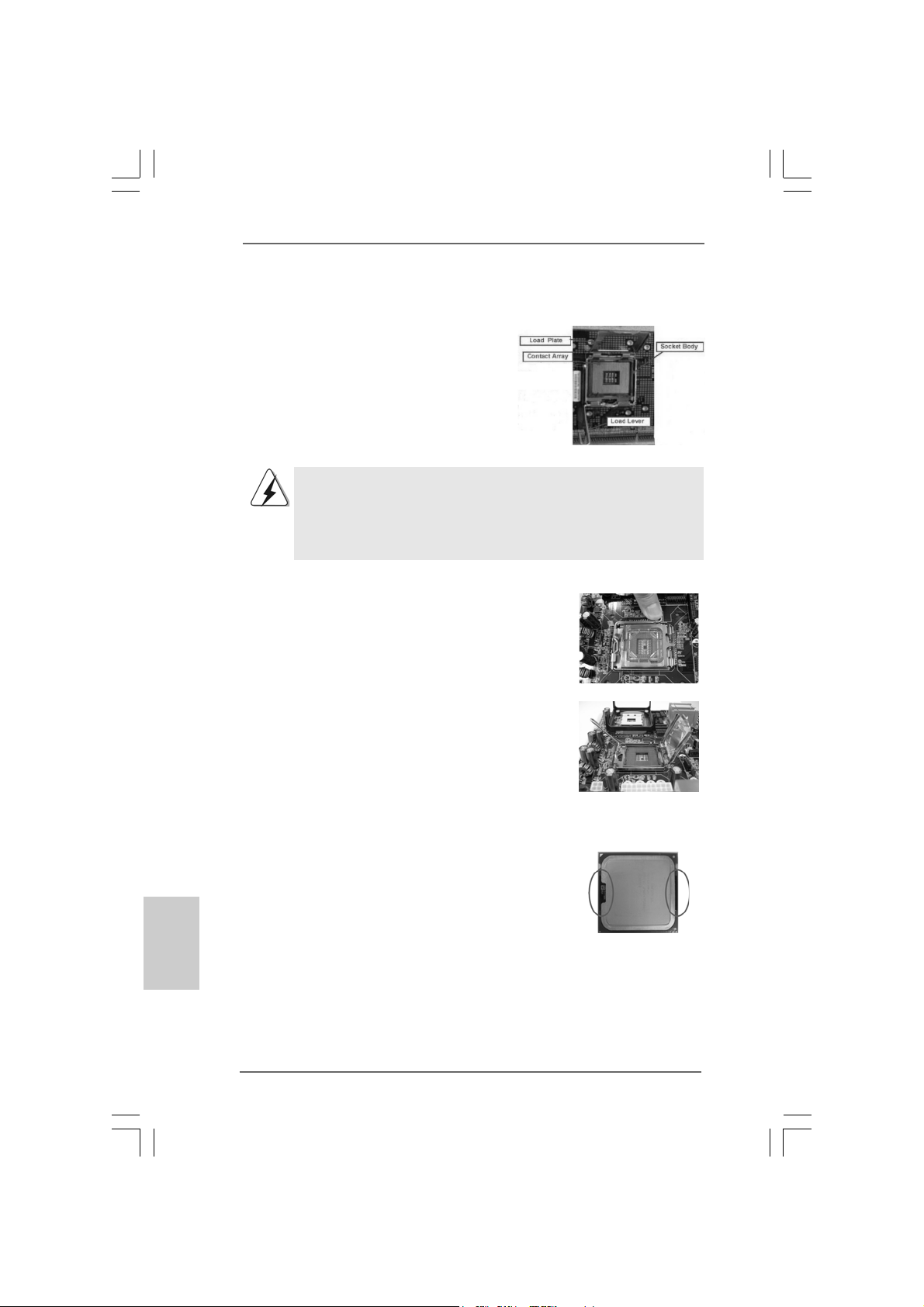
2.1 Installation du CPU2.1 Installation du CPU
2.1 Installation du CPU
2.1 Installation du CPU2.1 Installation du CPU
Pour l’installation du processeur Intel 775
broches, veuillez suivre la procédure
ci-dessous.
Avant d’insérer le processeur 775 broches dans le socket, veuillez
vérifier que la surface du processeur est bien propre, et qu’il n’y a
aucune broche tordue sur le socket. Si c’est le cas, ne forcez pas
pour insérer le processeur dans le socket. Sinon, le processeur
sera gravement endommagé.
Etape 1. Ouvrez le socle :
Etape 1-1. Dégagez le levier en appuyant sur
le crochet et en le faisant ressortir
pour dégager la languette de
retenue.
Etape 1-2. Faites tourner le levier de
chargement en position ouverte
maximum à 135 degrés.
Etape 1-3. Faites pivoter la plaque de
chargement pour l’ouvrir au
maximum à environ 100 degrés.
(Plaque de chargement)
(Barrette de contact)
Vue d’ensemble du socket 775 broches
(Corps du
socket)
Français
FrançaisFrançais
FrançaisFrançais
8888
88
8888
Etape 2. Insérez le processeur 775 broches :
Etape 2-1. Tenez le processeur par ses
bords là où se trouvent des lignes
noires.
Etape 2-2. Orientez le paquet avec le
dissipateur thermique intégré (IHS)
vers le haut. Repérez la broche 1
et les deux encoches
d’orientation.
ASRock 775XFire-RAID Motherboard
Ligne noire
Ligne noire
Page 89

broche 1
Encoche
d’orientation
Processeur 775 broches
Encoche
d’orientation
Pour une insertion correcte, veuillez vérifier que vous faites bien
correspondre les deux encoches d’orientation sur le processeur
avec les deux détrompeurs du socket
Détrompeur
Etape 2-3. Mettez soigneusement en place le
processeur dans le socle en un
mouvement strictement vertical.
Etape 2-4. Vérifiez que le processeur est
bien installé dans le socle et que
les encoches d’orientation sont
dans la bonne position.
Etap e 3. Enlevez le capuchon PnP (Pick et Place) :
De l’index et du de votre main gauche,
soutenez le bord de la plaque de
chargement, engagez le PnP avec le pouce
de votre main droite, et enlevez le capuchon
du socle tout en appuyant sur le centre du
capuchon PnP pour vous aider.
broche 1
Détrompeur
Socket 775 broches
.
1. Il est recommandé d’utiliser la languette du capuchon ; évitez de
faire sortir le capuchon PnP.
2. Ce capuchon doit être mis en place si vous renvoyez la carte
mère pour service après vente.
Etape 4. Refermez le socle :
Etape 4-1. Faites pivoter la plaque de
chargement sur l’IHS.
Etape 4-2. Tout en appuyant doucement sur
la plaque de chargement, engagez
le levier de chargement
Etape 4-3. Fixez le levier de chargement
avec la languette de la plaque de
chargement sous la languette de
retenue du levier de chargement.
ASRock 775XFire-RAID Motherboard
8989
89
8989
çaisçais
çaisçais
çais
FranFran
FranFran
Fran
Page 90
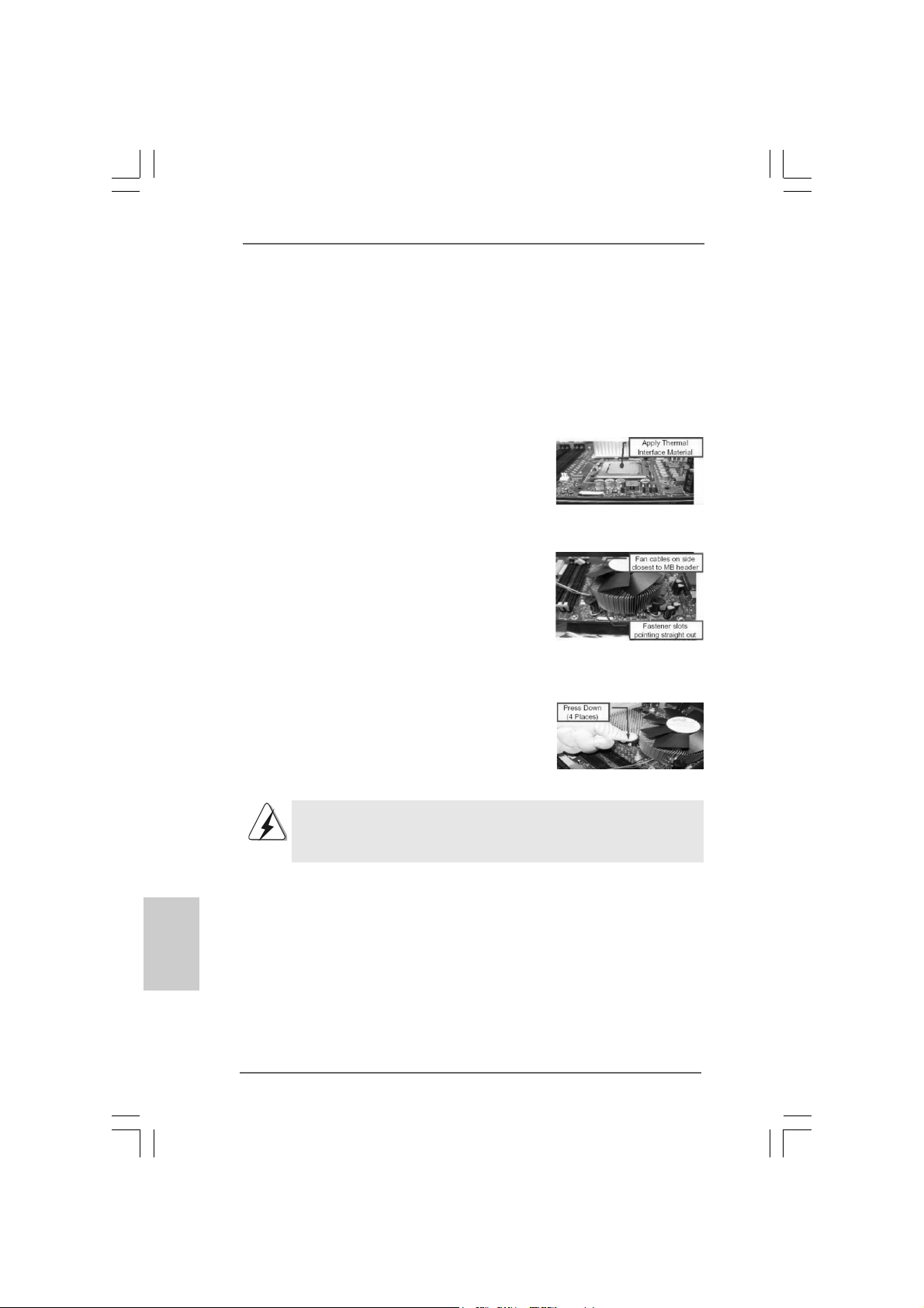
2.22.2
Installation du ventilateur du processeur etInstallation du ventilateur du processeur et
2.2
Installation du ventilateur du processeur et
2.22.2
Installation du ventilateur du processeur etInstallation du ventilateur du processeur et
dissipateur thermiquedissipateur thermique
dissipateur thermique
dissipateur thermiquedissipateur thermique
Pour une installation correcte, veuillez vous reporter aux manuels d’instructions de
votre ventilateur de processeur et de votre dissipateur thermique.
L’exemple ci-dessous illustre l’installation du dissipateur thermique pour un
processeur 775 broches.
Etape 1. Appliquez le matériau d’interface thermique
au centre de IHS sur la surface du socket.
Etape 2. Placez le dissipateur thermique sur le socket.
Vérifiez que les câbles du ventilateur sont
orientés vers le côté le plus proche du
connecteur pour ventilateur de processeur
sur la carte mère (CPU_FAN1, voir page 2,
no. 6).
Etape 3. Alignez les attaches avec la carte mère par
les orifices.
Etape 4. Faites tourner les attaches dans le sens des
aiguilles d’une montre, puis, du pouce,
enfoncez les capuchons des attaches pour
les installer et les verrouiller. Répétez
l’opération avec les autres attaches.
(Appliquez le matériau d’interface thermique)
(Câbles du ventilateur du côté le plus
proche du connecteur sur la carte mère)
(Orifices des attaches ressortant)
(Enfoncez (4 endroits))
Français
FrançaisFrançais
FrançaisFrançais
9090
90
9090
Si vous enfoncez les attaches sans les faire tourner dans le sens
des aiguilles d’une montre, le dissipateur thermique ne sera pas fixé
sur la carte mère.
Etape 5. Connectez l’en-tête du ventilateur sur le
connecteur pour ventilateur de processeur
sur la carte mère.
Etape 6. Fixez la longueur de câble en excès avec du
ruban adhésif pour vous assurer que le
câble ne gênera pas le fonctionnement du
ventilateur ou n’entrera pas en contact avec
les autres composants.
ASRock 775XFire-RAID Motherboard
Page 91

2.3 Installation des modules m émoire [DIMM]2.3 Installation des modules m émoire [DIMM]
2.3 Installation des modules m émoire [DIMM]
2.3 Installation des modules m émoire [DIMM]2.3 Installation des modules m émoire [DIMM]
La carte mère 775XFire-RAID dispose de quatre emplacements DIMM DDRII
(Double Data Rate II) de 240-broches, et supporte la Technologie de Mémoire à
Canal Double. Pour effectuer une configuration à canal double, vous devez
toujours installer des paires de DIMM DDRII identiques (de la même marque, de la
même vitesse, de la même taille et du même type de puce) dans les slots de même
couleur. En d’autres termes, vous devez in staller une paire de DIMM DDRII
identiques dans le Canal Double A (DDRII_1 et DD RII_3; slots jaune s; voir p.2 No. 7)
ou une paire de DIMM DDRII identique s da ns le Ca nal Double B (DD RII_2 et DDRII_4;
slots orange; voir p.2 No. 8), de façon à ce que la Technologie de Mémoire à Canal
Double puisse être activée. Cette carte vous permet également d’installer quatre
modules DIMM DDRII pour la configuration à can al double. Cette carte mère vous
permet également d’installer quatre modules DIMM DDRII pour une configuration
double canal; veuillez installer les mêmes module s DIMM DDRII dans les quatre
emplacements. Vous pouvez vous reporter au Tableau de configuration mémoire
double canal ci-dessous.
Configurations de Mémoire à Canal Double
DDRII_1 DDRII_2 DDRII_3 DDRII_4
(Slot Jaunes) (Slot Orange) (Slot Jaunes) (Slot Orange)
(1) Occupé - Occupé (2 ) - Occupé - Occupé
(3) Occupé Occupé Occupé Occupé
* Pour la configuration (3), veuillez installer des DIMM DDRII identiques dans les
quatre emplacements.
1. Si vous voulez installer deux modules de mémoire, pour une
compatibilité et une fiabilité optimales, il est recommandé de les
installer dans des emplacements de la même couleur. En d’autres
termes, installez-les soit dans les emplacements jaunes (DDRII_1 et
DDRII_3), soit dans les emplacements orange (DDRII_2 et
DDRII_4).
2. Si un seul module mémoire ou trois modules mémoire sont installés
dans les slots DIMM DDRII sur cette carte mère, il sera impossible
d’activer la Technologie de Mémoire à Canal Double.
3. Si une paire de modules mémoire N’est PAS installée dans le
même “Canal Double”, par exemple, installer une paire de modules
mémoire dans le DDRII_1 et le DDRII_2, il sera impossible
d’activer la Technologie de Mémoire à Canal Double.
4. Il n’est pas permis d’installer de la DDR sur le slot DDRII; la carte mère et
les DIMM pourraient être endommagés.
ASRock 775XFire-RAID Motherboard
9191
91
9191
çaisçais
çaisçais
çais
FranFran
FranFran
Fran
Page 92

Installation d’un module DIMMInstallation d’un module DIMM
Installation d’un module DIMM
Installation d’un module DIMMInstallation d’un module DIMM
Ayez bien le soin de débrancher l’alimentation avant d’ajouter ou de
retirer des modules DIMM ou les composants du système.
Etape 1. Déverrouillez un connecteur DIMM en poussant les taquets de maintien
vers l’extérieur.
Eta pe 2. Alignez le module DIMM sur son emplacement en faisant correspondre les
encoches du module DIMM aux trous du connecteur.
Le module DIMM s’insère uniquement dans un seul sens. Si vous
forcezle module DIMM dans son emplacement avec une mauvaise
orientation cela provoquera des dommages irrémédiables à la carte
mère et au module DIMM.
Français
FrançaisFrançais
FrançaisFrançais
9292
92
9292
Etape 3. Insérez fermement le module DIMM da n s son emplacement jusqu’à ce que
les clips de maintien situés aux deux extrémités se ferment complètement
et que le module DIMM soit inséré correctement.
ASRock 775XFire-RAID Motherboard
Page 93

2.4 Slots d’extension2.4 Slots d’extension
2.4 Slots d’extension
2.4 Slots d’extension2.4 Slots d’extension
(Slots PCI, PCI Express et AGI Express) (Slots PCI, PCI Express et AGI Express)
(Slots PCI, PCI Express et AGI Express)
(Slots PCI, PCI Express et AGI Express) (Slots PCI, PCI Express et AGI Express)
Il y a 3 slots PCI , 2 slots PCI Express et 1 slot AGI Express (PCI Express x 4) sur le s
cartes mères 775XFire-RAID.
Slots PCI: Les slots PCI sont utilisés pour installer des cartes d’extension dotées
d’une interface PCI 32 bits.
Slots PCIE: PCIE1 (emplacement PCIE x16) est utilisé pour le s carte s PCI Expre ss
avec cartes gra phique s de largeur x16 voie s. PCIE2 (emplacement PCIE
x1) est utilisé pour les cartes PCI Express, telles que les cartes
Gigabit LAN, les cartes SATA 2, etc. Veuillez vérifier les réglages des
cavaliers à la page 94 pour des fonctions différentes.
Slot AGI Express (PCI Express x 4):
L’emplacement AGI Express (PCI Express x 4) est utilisé pour installer
les cartes d’extension PCI Express. Pour les informations concernant
les cartes PCI Express VGA compatibles, veuillez vous reporter à la
“Liste des cartes PCI Express VGA prises en charge pour
l’emplacement AGI Express (PCI Express x 4)” page 8. Veuillez vérifier
les réglages des cavaliers à la page 94 pour des fonctions
différentes.
Installation d’une carte d’extensionInstallation d’une carte d’extension
Installation d’une carte d’extension
Installation d’une carte d’extensionInstallation d’une carte d’extension
Etape 1. Avant d’installer les cartes d’extension, veuillez vous assurer de bien
avoir coupé l’alimentation ou d’avoir débranché le cordon d’alimentation.
Veuillez lire la documentation des cartes d’extension et effectuer les
réglages matériels nécessaires pour les cartes avant de débuter
l’installation.
Etape 2. Retirez l’équerre correspondant au connecteur que vous voulez utiliser.
Gardez la vis pour un usage ultérieur.
Etap e 3. Alignez la carte sur le connecteur et appuyez ferme ment jus qu’à l’in sertion
complète de la carte dans son emplacement.
Etape 4. Fixez la carte sur le châssis à l’aide d’une vis.
ASRock 775XFire-RAID Motherboard
9393
93
9393
çaisçais
çaisçais
çais
FranFran
FranFran
Fran
Page 94

2.52.5
La caractéristique Dual GraphicLa caractéristique Dual Graphic
2.5
La caractéristique Dual Graphic
2.52.5
La caractéristique Dual GraphicLa caractéristique Dual Graphic
Cette carte mère prend en charge la technologie Dual Graphics. Lors de
l’installation de cartes VGA compagnon sur cette carte mère, vous pouvez choisir
deux façons différentes de décider la fonction de la fente PCIE2 (PCIE x 1) et de la
fente AGI Express. La valeur par défaut de cette fonctionnalité est d’activer la
fente PCIE2 (PCIE x 1) et la fente AGI Express (uniquement PCI Expre s s x 1). Vous
pouvez également ajuster les cavaliers pour désactiver la fente PCIE2 (PCIE x 1).
Ensuite seulement la fente AGI Express (PCI Express x 4) sera activée. En
d’autres termes, vous pouvez ajuster les cavaliers pour apprécier l’avantage de la
fonctionnalité Dual Graphics. Veuillez vous reporter à la table ci-dessous pour les
correctes configurations de cavalier.
Français
FrançaisFrançais
FrançaisFrançais
9494
94
9494
Fonction
Réglages des cavaliers
Active PCIE2 /
AGI Express
(seulement
PCIE x 1)
(Défaut)
PCIE x 1_EN3
PCIE x 1_EN4
PCIE x 1_EN2
PCIE x 1_EN1
PCIE x 1_EN5
Active AGI
Express
(PCIE x 4)
(Désactive
PCIE2)
2.62.6
Guide de Fonctionnement CrossFireGuide de Fonctionnement CrossFire
2.6
Guide de Fonctionnement CrossFire
2.62.6
Guide de Fonctionnement CrossFireGuide de Fonctionnement CrossFire
Cette carte mère supporte la fonction CrossFireTM. La technologie CrossFire
PCIE x 1_EN3
PCIE x 1_EN4
PCIE x 1_EN2
PCIE x 1_EN1
TMTM
TM
TMTM
PCIE x 1_EN5
TM
propose les moyens les plus avantageux disponibles en combinant plusieurs CPU
(Unité de traitement graphique) de haute performance dans un seul ordinateur. En
combinant une plage de modes de fonctionnement différents avec une conception
logicielle intelligente et un mécanisme d’interconnexion innovant, CrossFire
TM
autorise les meilleures performances et la meilleure qualité d’image pour n’importe
quelle application 3D. La fonction CrossFireTM est actuellement compatible
uniquement avec Windows XP avec le Service Pack 2; elle sera compatible avec
d’autres systèmes d’exploitation dans le futur.
ASRock 775XFire-RAID Motherboard
Page 95

Quelles cartes graphiques fonctionnent avec CrossFireTM?
Un système CrossFireTM complet nécessite une carte-mère CrossFire
Ready, une carte graphique CrossFireTM Edition et une carte graphique standard
compatible Radeon (CrossFireTM Ready) de la même série ou deux cartes
CrossFireTM Ready si elles sont activées pour le logiciel. Cela s’applique aux
cartes d’ATI ou de ses partenaires.
Cartes pour la fente AGI express Cartes pour la fente PCI express
Radeon série X1800 Radeon X1800 CrossFire TM Edition
Radeon série X1600 Radeon série X1600
Radeon série X1300 Radeon série X1300
Radeon série X850 Radeon X850 CrossFire TM Edition
TM
1. Si un client configure mal son système, il ne pourra pas bénéficier des
performances CrossFire
carte graphique compatible CrossFireTM , la carte mère compatible
CrossFireTM et la carte graphique du coprocesseur CrossFireTM Edition
doivent tous être installés correctement afin de pouvoir bénéficier des
x
Profiter des avantages de CrossFireProfiter des avantages de CrossFire
Profiter des avantages de CrossFire
Profiter des avantages de CrossFireProfiter des avantages de CrossFire
avantages de la plate-forme multi-GPU CrossFireTM.
2. Si vous associez une carte CrossFireTM Edition “12-pipe” avec une carte “16 pipe”, les deux cartes fonctionneront comme des cartes “12-pipe” en mode
CrossFireTM.
Actuellement, ATI a mis sur le marché les cartes Radeon X850XT, X1800XT,
X1300, et X1600 CrossFireTM, qui exigent différentes méthodes afin d’activer la
fonctionnalité CrossFireTM. Dans les procédures ci-dessous, nous utilisons la
Radeon X850XT comme exemple de carte graphique. Pour d’autres cartes
CrossFire
reporter aux manuels de cartes graphiques d’ATI pour le guide d’installation
détaillé.
TM
qu’ATI a mis ou mettra sur le marché à l’avenir, veuillez vous
TM.
Les trois composants CrossFireTM, à savoir la
TMTM
TM
TMTM
Etape 1. Réglez les cavaliers sur la carte mère pour activer le slot AGI Express
slot (PCI Express x 4). Veuillez vous référer aux figures ci-dessous
pour connaître le réglage des cavaliers approprié.
çaisçais
çaisçais
çais
FranFran
FranFran
Fran
PCIEx1_EN1-4: Court-circuiter
la broche 1 et la broche 2
ASRock 775XFire-RAID Motherboard
PCIEx1_EN5: Court-circuiter
la broche 1 et la broche 2
9595
95
9595
Page 96

Etape 2. Réalisez la connexion avec l’alimentation du système. Veuillez
connecter un connecteur d’alimentation pour disque dur sur le
connecteur d’alimentation SLI/XFIRE.
Il est recommandé d’utiliser une alimentation d’une
puissance de 500-Watts ou plus pour pouvoir profiter
des avantages de la fonction CrossFireTM.
Etape 3. Installez la carte graphique Radeon standard (compatible CrossFireTM)
sur le slot AGI Express (PCI Express x 4). Pour connaître les
procédures d’installation appropriées, référez-vous à la section “Slots
d’extension”.
Carte graphique Radeon
(compatible CrossFireTM)
standard
Etape 4. Installez la carte graphique Radeon CrossFireTM Edition sur le slot PCI
Express x 16. Pour connaître les procédures d’installation
appropriées, référez-vous à la section “Slots d’extension”.
Français
FrançaisFrançais
FrançaisFrançais
9696
96
9696
Carte graphique Radeon
CrossFire
Carte graphique Radeon
(compatible CrossFireTM)
standard
TM
Edition
Vous pouvez installer deux cartes graphiques CrossFire
slots ou vous pouvez également utiliser une carte graphique CrossFireTM Edition
et une carte graphique Radeon (Compatible CrossFireTM ) standard compatible
de la même série.
TM
Edition sur les deux
Etape 5. Connectez correctement le câble DVI-DMS sur le connecteur du
moniteur et sur les deux cartes graphiques installées. (Si vous
installez deux cartes graphiques standard Radeon (CrossFire
Ready) à cette carte mère, passez cette étape.)
Câble DVI-DMS
Connecteur DMS
Connecteur DVI
ASRock 775XFire-RAID Motherboard
TM
Page 97

Carte graphique Radeon (compatible
CrossFireTM) standard
Connecteur DVI
Connectez le câble DVI-DMS
sur le connecteur DVI de la
carte graphique Radeon
(Compatible CrossFireTM )
standard compatible.
Carte graphique
Radeon CrossFire
Edition
Il existe deux connecteurs DVI sur la carte
graphique Radeon (Compatible CrossFire
standard. Veuillez connecter le câble DVI-DMS
sur le bon connecteur DVI; dans le cas
contraire, la carte graphique ne fonctionnera
pas.
TM
Connecteur
TM
DMS
Connectez le câble DVI-DMS
sur le connecteur DMS de la
carte graphique CrossFire
Edition.
Si vous installez deux cartes graphiques CrossFireTM Edition sur la carte mère,
veuillez connecter une extrémité du câble DVI-DMS sur le moniteur, une
extrémité sur le connecteur DMS de l’une des cartes graphiques CrossFire
Edition sur le slot PCIE1(PCI Express x 16), et l’autre extrémité sur le
connecteur DVI de la deuxième carte graphique CrossFireTM Edition sur le slot
AGI Express (PCI Express x 4). Si vous installez une carte graphique
CrossFireTM Edition et une carte graphique Radeon (Compatible CrossFireTM )
standard compatible sur la carte mère, veuillez connecter une extrémité du
câble DVI-DMS sur le moniteur, une extrémité sur le connecteur DMS de la
carte graphique CrossFireTM Edition et la troisième extrémité sur le connecteur
DVI de la carte graphique Radeon (Compatible CrossFireTM) standard
compatible.
TM
Connectez le câble DVI-DMS
sur le connecteur du
moniteur.
TM
)
Etape 6. Allumez votre ordinateur et démarrez dans le système d’exploitation.
Etape 7. Supprimez le pilote ATI si vous avez déjà installé un pilote VGA sur
votre système.
Le programme de désinstallation ‘Catalyst Uninstaller’ est un téléchargement
optionnel. Nous vous recommandons d’utiliser cet utilitaire pour désinstaller les
pilotes Catalyst précédemment installés avant l’installation.
Veuillez visiter ce site web pour obtenir le pilote:
http://support.ati.com/ics/support/DLRedirect.asp?
fileIDExt=050553d40196ef109fff37cbb40aaf28&accountID=737&deptID=894
ASRock 775XFire-RAID Motherboard
9797
97
9797
çaisçais
çaisçais
çais
FranFran
FranFran
Fran
Page 98

Etape 8. Installez les pilotes requis sur votre système. Veuillez visiter les sites
web ci-dessous pour installer les pilotes recommandés par ATI:
A. ATI recommande d’installer Windows XP Service Pack 2 ou plus
(Si vous avez déja installé Windows XP Service Pack 2 ou plus
sur votre systéme, il n’est pas nécessaire de le télécharger de
nouveau):
http://www.microsoft.com/windowsxp/sp2/default.mspx
B. Vous devez au préalable avoir Microsoft .NET Framework installé
avant de télécharger et d’installer CATALYST Control Center:
http://www.microsoft.com/downloads/details.aspx?
FamilyId=262D25E3-F589-4842-8157-
034D1E7CF3A3&displaylang=en
Etape 9. Redémarrez votre ordinateur.
Etape 10. Installez les pilotes de la carte VGA sur votre système et redémarrez
votre ordinateur. Vous trouverez ensuite l’icône “ATI Catalyst Control
Center” sur votre bureau (le pilote ATI Catalyst doit être de la version
5.10 ou plus).
Vous trouverez l’icône
“ATI Catalyst Control
Center” sur votre
bureau.
Français
FrançaisFrançais
FrançaisFrançais
9898
98
9898
ASRock 775XFire-RAID Motherboard
Page 99

Etape 11. Double-cliquez sur l’icône “ATI Catalyst Control Center”. Cliquez sur
“View (Affichage)” et sélectionnez “Advanced View (Affichage
Avancé)”. Cliquez sur “CrossFireTM” puis réglez l’option “Enable
CrossFireTM (Activer CrossFireTM)” sur “Yes[Oui]”.
Affichage
CrossFire
t
TM
Si vous installez une carte graphique Radeon CrossFireTM Edition et une carte
graphique Radeon (Compatible CrossFireTM) standard compatible sur cette carte
mère au lieu de deux cartes graphiques Radeon CrossFireTM Edition, veuillez
également suivre les étapes ci-dessus. Cependant, bien que vous ayez
sélectionné l’option “Enable CrossFire
CrossFireTM ne sera pas disponible. Votre ordinateur redémarrera
automatiquement. Après le redémarrage de votre ordinateur, veuillez vérifier si
l’option “Enable CrossFireTM (Activer CrossFireTM) dans “ATI Catalyst Control
Center” est sélectionnée ou pas; dans la négative, veuillez la sélectionner une
nouvelle fois et vous pourrez maintenant profiter des avantages de la fonction
TM
CrossFire
.
TM
(Activer CrossFireTM), la fonction
Activer CrossFire
TM
Etape 12. Vous pouvez profiter librement des avantages de la fonction
CrossFireTM.
* Le terme CrossFire
ATI Technologies Inc., et est utilisé uniquement à des fins d’identification ou d’explication et
pour les bénéfices de l’utilisateur sans aucune intention de violation.
TM
présent dans ce document est une marque commerciale déposée de
ASRock 775XFire-RAID Motherboard
9999
99
9999
çaisçais
çaisçais
çais
FranFran
FranFran
Fran
Page 100

2.7 “Surround Display”2.7 “Surround Display”
2.7 “Surround Display”
2.7 “Surround Display”2.7 “Surround Display”
Cette carte mère supporte la mise à niveau de Surround Display. Avec la carte
externe d’extension VGA PCI Express, vous pouvez facilement jouir des
avantages de la caractéristique de l’affichage Surround. Pour les instructions
détaillées, veuillez vous reporter au document qui se trouve sur le chemin suivant
dans le CD d’assistance : ..\ Surround Display Information
2.8 Réglage des cavaliers2.8 Réglage des cavaliers
2.8 Réglage des cavaliers
2.8 Réglage des cavaliers2.8 Réglage des cavaliers
L’illustration explique le réglage des cavaliers.
Quand un capuchon est placé sur les broches,
le cavalier est « FERME ». Si aucun capuchon
ne relie les broches,le cavalier est « OUVERT ».
L’illustration montre un cavalier à 3 broches dont
les broches 1 et 2 sont “FERMEES” quand le
capuchon est placé sur ces 2 broches.
Le cavalier Des cription
PS2_USB_PWR1 Court-circuitez les broches 2
(voir p.2 No. 1) et 3 pour choisir +5VSB
Note: Pour sélectionner +5VSB, il faut obligatoirement 2 Amp et un courant
standby supérieur fourni par l’alimentation.
Ferme Ouvert
(standby) et permettre aux
périphériques PS/2 ou USB de
réveiller le système.
Français
FrançaisFrançais
FrançaisFrançais
100100
100
100100
Effacer la CMOS
(CLRCMOS1,
le cavalier à 2 broches)
(voir p.2 No. 10)
Note: CLRCMOS1 vous permet d’effacer les données de la CMOS. Ces données
incluent les informations système telles que le mot de passe, la date, l’heure,
et les paramètres du système. Pour restaurer les paramètres système à leur
valeur par défaut, éteignez l’ordinateur et débranchez le câble
d’alimentation. Puis placez un cavalier sur les pins CLRCMOS1 pendant 3
secondes. N’oubliez pas de retirer le cavalier avant après avoir restauré le
CMOS.
le cavalier à 2 broches
ASRock 775XFire-RAID Motherboard
 Loading...