

Page 1
Copyright Notice:Copyright Notice:
Copyright Notice:
Copyright Notice:Copyright Notice:
No part of this installation guide may be reproduced, transcribed, transmitted, or
translated in any language, in any form or by any means, except duplication of
documentation by the purchaser for backup purpose, without written consent of
ASRock Inc.
Products and corporate names appearing in this guide may or may not be registered
trademarks or copyrights of their respective companies, and are used only for
identification or explanation and to the owners’ benefit, without intent to infringe.
Disclaimer:Disclaimer:
Disclaimer:
Disclaimer:Disclaimer:
Specifications and information contained in this guide are furnished for informational
use only and subject to change without notice, and should not be constructed as a
commitment by ASRock. ASRock assumes no responsibility for any errors or
omissions that may appear in this guide.
With respect to the contents of this guide, ASRock does not provide warranty of any
kind, either expressed or implied, including but not limited to the implied warranties or
conditions of merchantability or fitness for a particular purpose.
In no event shall ASRock, its directors, officers, employees, or agents be liable for
any indirect, special, incidental, or consequential damages (including damages for
loss of profits, loss of business, loss of data, interruption of business and the like),
even if ASRock has been advised of the possibility of such damages arising from any
defect or error in the guide or product.
This device complies with Part 15 of the FCC Rules. Operation is subject to the
following two conditions:
(1) this device may not cause harmful interference, and
(2) this device must accept any interference received, including interference that
may cause undesired operation.
ASRock Website: http://www.asrock.com
Published April 2006
Copyright©2006 ASRock INC. All rights reserved.
ASRock 775XFire-eSATA2+ Motherboard
EnglishEnglish
EnglishEnglish
English
11
1
11
Page 2
Motherboard LMotherboard L
Motherboard L
Motherboard LMotherboard L
ayoutayout
ayout
ayoutayout
English
EnglishEnglish
EnglishEnglish
22
2
22
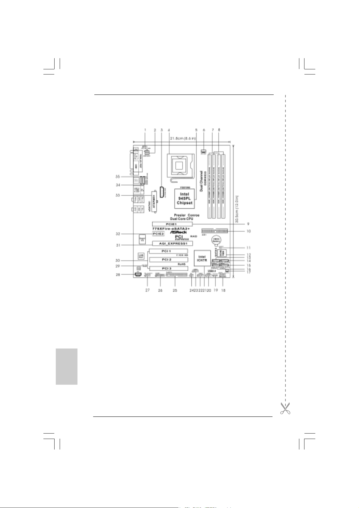
1 PS2_USB_PWR1 Jumper 18 System Panel Hea der (P ANEL1)
2 A TX 12V Connector (A TX12V1) 19 Chassis Speaker Header (SPEAKER 1)
3 SLI / XFIRE Power Connector 20 USB 2.0 Header (USB67, Blue)
4 775-Pin CPU Socket 21 South Bridge Controller
5 North Bridge Controller 22 USB 2.0 Header (USB45, Blue)
6 CPU Fan Connector (CPU_FAN1) 23 USB 2.0 Header (USB23, Blue)
7 2 x 240-pin DDRII DIMM Slots 24 Infrared Module Connector (IR1)
(Dual Channel A: DDRII_1, DDRII_3; Yellow) 25 Floppy Connector (FLOPPY1)
8 2 x 240-pin DDRII DIMM Slots 26 Game Port Header (GAME1)
(Dual Channel B: DDRII_2, DDRII_4; Orange) 27 Front Panel Audio Header (HD_AUDIO1)
9 PCI Express x16 Slot (PCIE1) 28 Internal Audio Connector: CD1 (Black)
10 IDE1 Connector (IDE1, Blue) 29 HDMI_SPDIF Header (HDMI_SPDIF1)
11 Clear CMOS Jumper (CLRCMOS1) 30 PCI Slots (PCI1- 3)
12 BIOS FWH Chip 31 AGI Express Slot (PCI Express x4)
13 Serial ATAII Connector (SATAII_RED (PORT2)) 32 PCI Express x1 Slot (PCIE2)
14 Serial A T AII Connector (SATAII_ORANGE (PORT3)) 33 ATX Power Connector (ATXPWR1)
15 Serial ATAII Connector (SA TAII_BLACK (PORT1)) 34 eSA T AII Connector (eSA T AII_BOTT OM)
16 Serial A TAII Connector (SAT AII_BLUE (PORT0)) 35 eSA T AII Connector (eSATAII_TOP)
17 Chassis Fan Connector (CHA_FAN1)
ASRock 775XFire-eSATA2+ Motherboard
Page 3
ASRASR
ock 8CH_eSock 8CH_eS
ASR
ock 8CH_eS
ASRASR
ock 8CH_eSock 8CH_eS
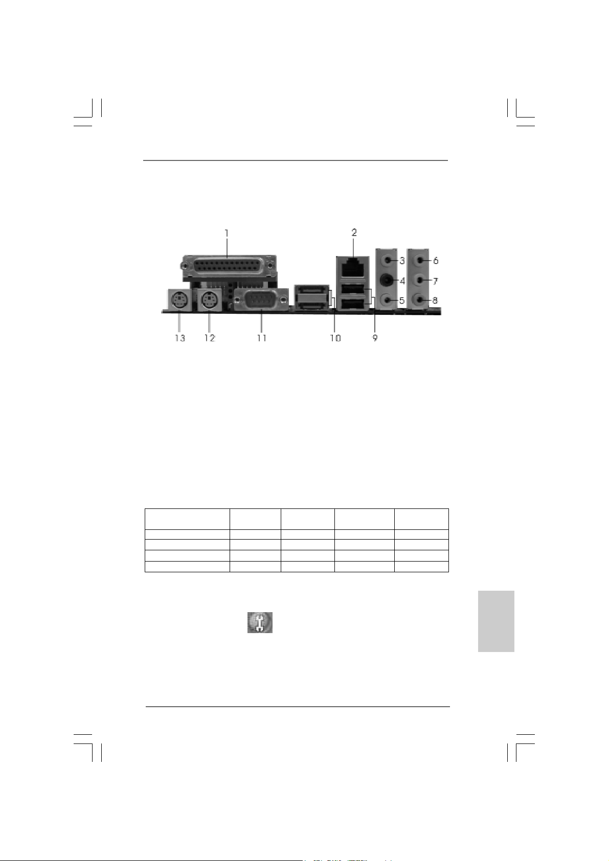
1 Parallel Port 8 Microphone (Pink)
2 RJ-45 Port 9 USB 2.0 Ports (USB01)
3 Side Speaker (Gray) 10 eSATAII Ports
4 Rear Speaker (Black) 11 COM Port
5 Central / Bass (Orange) 12 PS/2 Keyboard Port (Purple)
6 Line In (Light Blue) 13 PS/2 Mouse Port (Green)
*7 Front Speaker (Lime)
* If you use 2-channel spea ker, please connect the speaker’s plug into “Front Speaker Jack”. See
the table below for connection details in accordance with the type of speaker you use.
AA
TT
AII I/OAII I/O
A
T
AII I/O
AA
TT
AII I/OAII I/O
TABLE for Audio Output Connection
Audio Output Channels Front Speaker Rear Speaker Central / Bass Side Speaker
(No. 7) (No. 4) (No. 5) (No. 3)
2 V -- -- -4VV---6 VVV-8 VVVV
* To enable Multi-Streaming function, you need to connect a front panel audio cable to the front
panel audio header. After restarting your computer, you will find “Mixer” tool on your system.
Please select “Mixer ToolBox” , click “Enable playback multi-streaming”, and click
“ok”. Choose “2CH”, “4CH”, “6CH”, or “8CH” and then you are allowed to select “Realtek HDA
Primary output” to use Rear Speaker, Central/Bass, and Front Speaker, or select “Realtek HDA
Audio 2nd output” to use front panel audio.
ASRock 775XFire-eSATA2+ Motherboard
EnglishEnglish
EnglishEnglish
English
33
3
33
Page 4
1. Introduction1. Introduction
1. Introduction
1. Introduction1. Introduction
Thank you for purchasing ASRock 775XFire-eSATA2+ motherboard, a reliable
motherboard produced under ASRock’s consistently stringent quality control. It delivers excellent performance with robust design conforming to ASRock’s commitment to quality and endurance.
This Quick Installation Guide contains introduction of the motherboard and step-bystep installation guide. More detailed information of the motherboard can be found in
the user manual presented in the Support CD.
Because the motherboard specifications and the BIOS software might be
updated, the content of this manual will be subject to change without
notice. In case any modifications of this manual occur, the updated
version will be available on ASRock website without further notice. You
may find the latest VGA cards and CPU support lists on ASRock website
as well. ASRock website
1.1 Package Contents1.1 Package Contents
1.1 Package Contents
1.1 Package Contents1.1 Package Contents
ASRock 775XFire-eSATA2+ Motherboard
(ATX Form Factor: 12.0-in x 8.6-in, 30.5 cm x 21.8 cm)
ASRock 775XFire-eSATA2+ Quick Installation Guide
ASRock 775XFire-eSATA2+ Support CD
(including LGA 775 CPU Installation Live Demo)
One 80-conductor Ultra ATA 66/100 IDE Ribbon Cable
One Ribbon Cable for a 3.5-in Floppy Drive
Four Serial AT A (SAT A) Data Cables (Optional)
Two Serial ATA (SATA) HDD Power Cables (Optional)
One HDMI_SPDIF Cable (Optional)
One ASRock 8CH_eSATAII I/O Pa nel Shield
One USB Bracket
http://www.asrock.com
English
EnglishEnglish
EnglishEnglish
44
4
44
ASRock 775XFire-eSATA2+ Motherboard
Page 5
1.21.2
SpecificationsSpecifications
1.2
Specifications
1.21.2
SpecificationsSpecifications
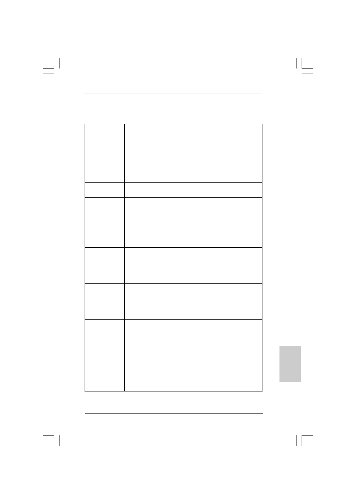
Platform - ATX Form Factor: 12.0-in x 8.6-in, 30.5 cm x 21.8 cm
CPU - LGA 775 f or Intel® Dual Core Pentium® D / Pentium® 4 / Celeron
D, supporting Conroe, Presler and Cedar Mill processors
(in 775-land LGA package)
- FSB 800/533 MHz
- Supports Hyper-Threading Technology (see CAUTION 1)
- Supports Untied Overclocking Technology (see CAUTION 2)
- Supports EM64T CPU
Chipset - Northbridge: Intel® 945PL chipset
- Southbridge: Intel® ICH7R
Memory - Dual Channel DDRII Memory Technology (see CAUTION 3)
- 4 x DDRII DIMM slots
- Support DDRII533 (see CAUTION 4)
- Max. capacity: 2GB
Hybrid Booster - CPU Frequency Stepless Control (see CAUTION 5)
- ASRock U-COP (see CAUTION 6)
- Boot Failure Guard (B.F.G.)
Expansion Slot - Supports ATI® CrossFire
- 3 x PCI slots
- 1 x PCI Express x16 slot
- 1 x AGI Express slot (PCI Express x4) (see CAUTION 7)
- 1 x PCI Express x1 slot
Audio - Realtek ALC888 7.1 channel CODEC with High Definition
Audio
LAN - Realtek PCI LAN 8101L
- Speed: 10/100 Ethernet
- Supports Wake-On-LAN
Rear Panel I/O ASRock 8CH_eSA T AII I/O
- 1 x PS/2 Mouse Port
- 1 x PS/2 Keyboard Port
- 1 x Serial Port: COM1
- 1 x Parallel Port (ECP/EPP Support)
- 2 x Ready-to-Use USB 2.0 Ports
- 2 x eSATAII Ports
- 1 x RJ-45 LAN Port
- HD Audio Jack: Side Speaker/Rear Speaker/Central Bass/
Line in/Front Speaker/Microphone (see CAUTION 8)
TM
®
EnglishEnglish
EnglishEnglish
English
ASRock 775XFire-eSATA2+ Motherboard
55
5
55
Page 6
English
EnglishEnglish
EnglishEnglish
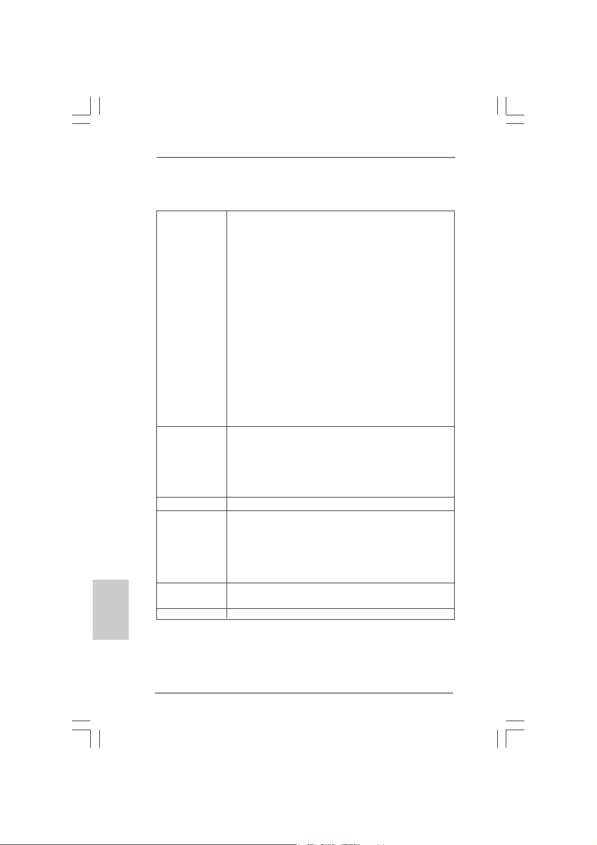
Connector - 4 x Serial ATAII 3.0Gb/s connectors, support RAID (RAID 0,
RAID 1, RAID 10, RAID 5, and Intel Matrix Storage), NCQ,
AHCI and “Hot Plug” functions (see CAUTION 9)
- 2 x eSATAII 3.0Gb/s connectors (shared with 2 SATAII
connectors), support “Hot Plug” function (see CAUTION 10)
- 1 x ATA100 IDE connector (supports 2 x IDE devices)
- 1 x Floppy connector
- 1 x IR header
- 1 x Game header
- 1 x HDMI_SPDIF header
- CPU/Chassis FAN connector
- 20 pin ATX power connector
- 4 pin 12V power connector
- SLI/XFIRE power connector
- CD in header
- Front panel audio connector
- 3 x USB 2.0 headers (support 6 USB 2.0 ports)
(see CAUTION 11)
BIOS Feature - 4Mb AMI BIOS
- AMI Legal BIOS
- Supports “Plug and Play”
- ACPI 1.1 Compli ance Wake Up Events
- Supports jumperfree
- SMBIOS 2.3.1 Support
Support CD - Drivers, Utilities, AntiVirus Software (Trial Version)
Hardware - CPU Temperature Sensing
Monitor - Chassis Temperature Sensing
- CPU Fan Tachometer
- Chassis Fan Tachometer
- CPU Quiet Fan
- Voltage Monitoring: +12V, +5V, +3.3V, Vcore
OS - Microsoft® Windows® 2000/XP/XP 64-bit/VistaTM compliant
(see CAUTION 12)
Certifications - FCC, CE, WHQL
66
6
66
ASRock 775XFire-eSATA2+ Motherboard
Page 7
CAUTION!
1. About the setting of “Hyper Threading Technology”, please check page 44
of “User Manual” in the support CD.
2. This motherboard supports Untied Overclocking Technology. Please read “Untied Overclocking Technology” on page 36 of “User Manual” in the support CD
for details.
3. This motherboard supports Dual Channel Memory Technology. Before you
implement Dual Channel Memory Technology, make sure to read the
installation guide of memory modules on page 13 for proper installation.
4. There are memory module installation limitations on this motherboard,
please read “Installation of Memory Modules (DIMM)” on page 13 for
details.
5. Although this motherboard offers stepless control, it is not recommended
to perform over-clocking. Frequencies other than the recommended CPU
bus frequencies may cause the instability of the system or damage the
CPU.
6. While CPU overheat is detected, the system will automatically shutdown.
Before you resume the system, please check if the CPU fan on the
motherboard functions properly and unplug the power cord, then plug it
back again. To improve heat dissipation, remember to spray thermal
grease between the CPU a nd the he atsink when you in stall the PC system.
7. For the information of the compatible PCI Express VGA cards, please
refer to the “Supported PCI Express VGA Card List for AGI Express Slot
(PCI Express x4)” on page 9. For the proper installation of PCI Express
VGA card, please refer to the installation guide on page 15.
8. For microphone input, this motherboard supports both stereo and mono
modes. For audio output, this motherboard supports 2-channel, 4-channel,
6-channel, and 8-channel modes. Please check the table on page 3 for
proper connection.
9. Before installing SATAII hard disk to SATAII connector, please read the
“SATAII Hard Disk Setup Guide” on page 30 to a djust your SATAII hard disk
drive to SATAII mode. Besides, you are allowed to downgrade the SATAII
hard disk to SATA hard disk (from SATAII 3Gb/s down to SATA 1.5Gb/s),
and connect it to the SATAII connector. You can also connect SATA hard
disk to SATAII connector directly.
10. This motherboard supports eSATAII interface, the external SATAII
specification. Please read “eSATAII Interface Introduction” on page 27 for
details about eSATAII and eSATAII installation procedures. (Port Multiplier
Technology is not supported with eSATAII interface on this motherboard.)
11. Power Management for USB 2.0 works fine under Microsoft® Windows
VistaTM / XP 64-bit / XP SP1 or SP2 / 2000 SP4.
12. Microsoft® Windows® VistaTM driver is not ready yet. We will update it to our
website in the future. Please visit our website for Microsoft® Windows® Vista
driver and related information.
ASRock website http://www.asrock.com
®
EnglishEnglish
EnglishEnglish
English
TM
ASRock 775XFire-eSATA2+ Motherboard
77
7
77
Page 8
1.31.3
Minimum Hardware RMinimum Hardware R
1.3
Minimum Hardware R
1.31.3
Minimum Hardware RMinimum Hardware R
TMTM
TM
TMTM
VistaVista
Vista
VistaVista
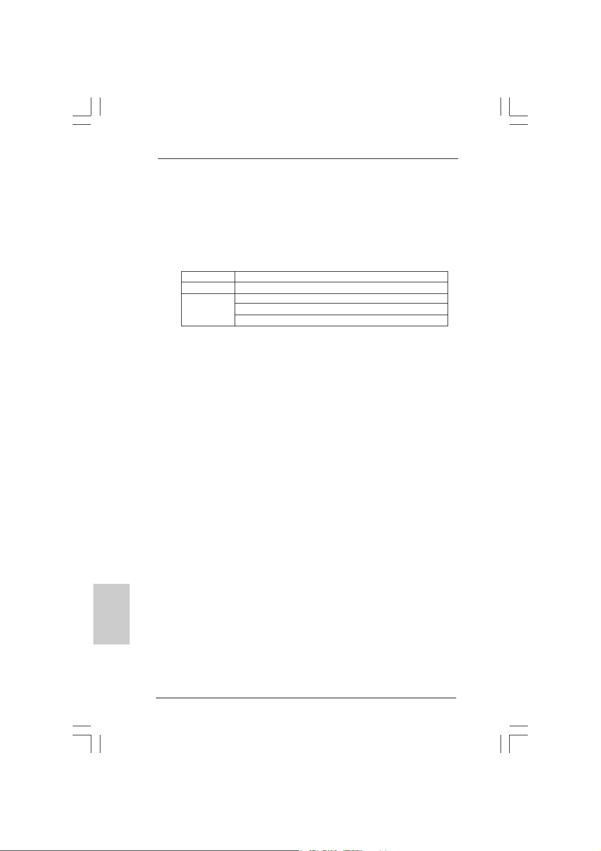
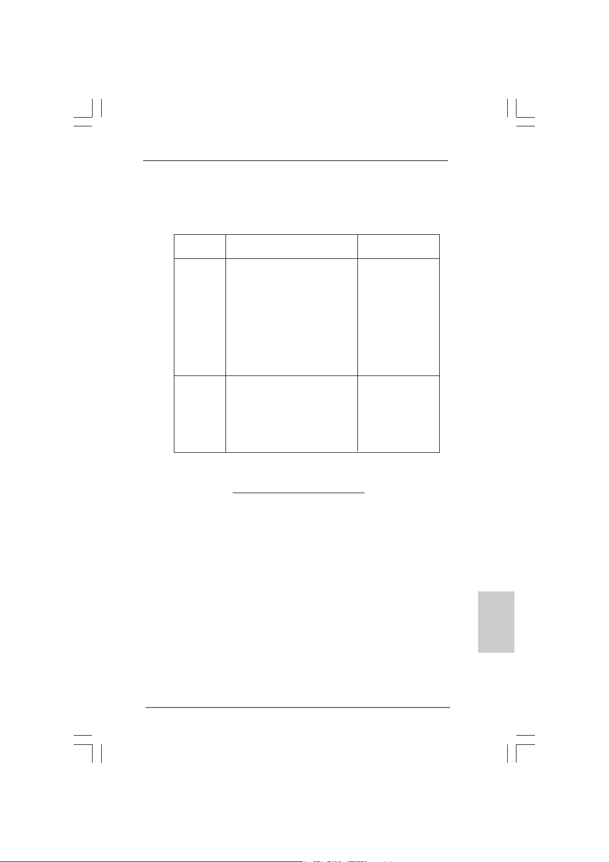
For system integrators and users who purchase this motherboard and
plan to submit Windows® VistaTM Premium and Basic logo, please follow the
below table for minimum hardware requirement. Please adopt the CPU,
memory, and VGA that we suggest.
CPU Celeron D 326
Memory 512MB Single Channel
VGA DX9.0 with WDDM Driver
Premium and Basic Logo Premium and Basic Logo
Premium and Basic Logo
Premium and Basic Logo Premium and Basic Logo
with 128bit VGA memory (Premium)
with 64bit VGA memory (Basic)
equirement Tequirement T
equirement T
equirement Tequirement T
able for Wable for W
able for W
able for Wable for W
indowsindows
indows
indowsindows
®®
®
®®
English
EnglishEnglish
EnglishEnglish
88
8
88
ASRock 775XFire-eSATA2+ Motherboard
Page 9
1.41.4
Supported PCI Express VGA Card List for AGISupported PCI Express VGA Card List for AGI
1.4
Supported PCI Express VGA Card List for AGI
1.41.4
Supported PCI Express VGA Card List for AGISupported PCI Express VGA Card List for AGI
Express Slot (PCI Express x4)Express Slot (PCI Express x4)
Express Slot (PCI Express x4)
Express Slot (PCI Express x4)Express Slot (PCI Express x4)
(for Windows® 2000/XP/XP 64-bit/VistaTM)
Graphics Chip Model Name Chipset Name
Vendor
NVIDIA ASUS Extreme N6200GE/TD GeForce 6200
ASUS Extreme N6200TC256/TD GeForce 6200
ASUS Extreme N6800GT GeForce 6800GT
ASUS Extreme N6800/TD GeForce 6800
ASUS Extreme 7800GTX/2DHTV/256M GeForce 7800 GTX
Albatron PC6600GT GeForce 6600GT
Gigabyte GV -NX66128D GeForce 6600
Inno3D GeFORCE 6600 LE GeForce 6600LE
Leadtek PX6200 TC/TDH GeForce 6200TC
MSI PCX 5750-TD128E GeForce PCX5750
SPARKLE GeFORCE 6200TC GeForce 6200TC
ATI ASUS Extreme AX600XT/HTVD RADEON X600XT
ASUS Extreme AX700PRO/TVD
Gecube Radeon X850XT 256M RADEON X850XT
Gecube RX1600XTG3-D3/256M
Gecube RX1300PG2-D3/256M
MSI RX1300GPRO-TD256E
MSI RX1600GPRO-TD256E
For the latest updates of the supported PCI Express VGA card list for AGI Express
slot (PCI Express x4), please visit our website for details.
ASRock website: http://www.asrock.com/support/index.htm
RADEON X700PRO
RADEON X1600XT
RADEON X1300PRO
RADEON X1300PRO
RADEON X1600PRO
ASRock 775XFire-eSATA2+ Motherboard
EnglishEnglish
EnglishEnglish
English
99
9
99
Page 10
2.2.
InstallationInstallation
2.
Installation
2.2.
InstallationInstallation
Pre-installation PrecautionsPre-installation Precautions
Pre-installation Precautions
Pre-installation PrecautionsPre-installation Precautions
Take note of the following precautions before you install motherboard components or change any motherboard settings.
1. Unplug the power cord from the wall socket before touching any
component. Failure to do so may cause severe damage to the
motherboard, peripherals, and/or components.
2. To avoid damaging the motherboard components due to static
electricity, NEVER place your motherboard directly on the carpet
or the like. Also remember to use a grounded wrist strap or touch
a safety grounded object before you handle components.
3. Hold components by the edges and do not touch the ICs.
4. Whenever you uninstall any component, place it on a grounded
antstatic pad or in the bag that comes with the component.
5. When placing screws into the screw holes to secure the
motherboard to the chassis, please do not over-tighten the
screws! Doing so may damage the motherboard.
2.12.1
CPU InstallationCPU Installation
2.1
CPU Installation
2.12.1
CPU InstallationCPU Installation
For the installation of Intel 775-LAND CPU,
please follow the steps below.
English
EnglishEnglish
EnglishEnglish
1010
10
1010
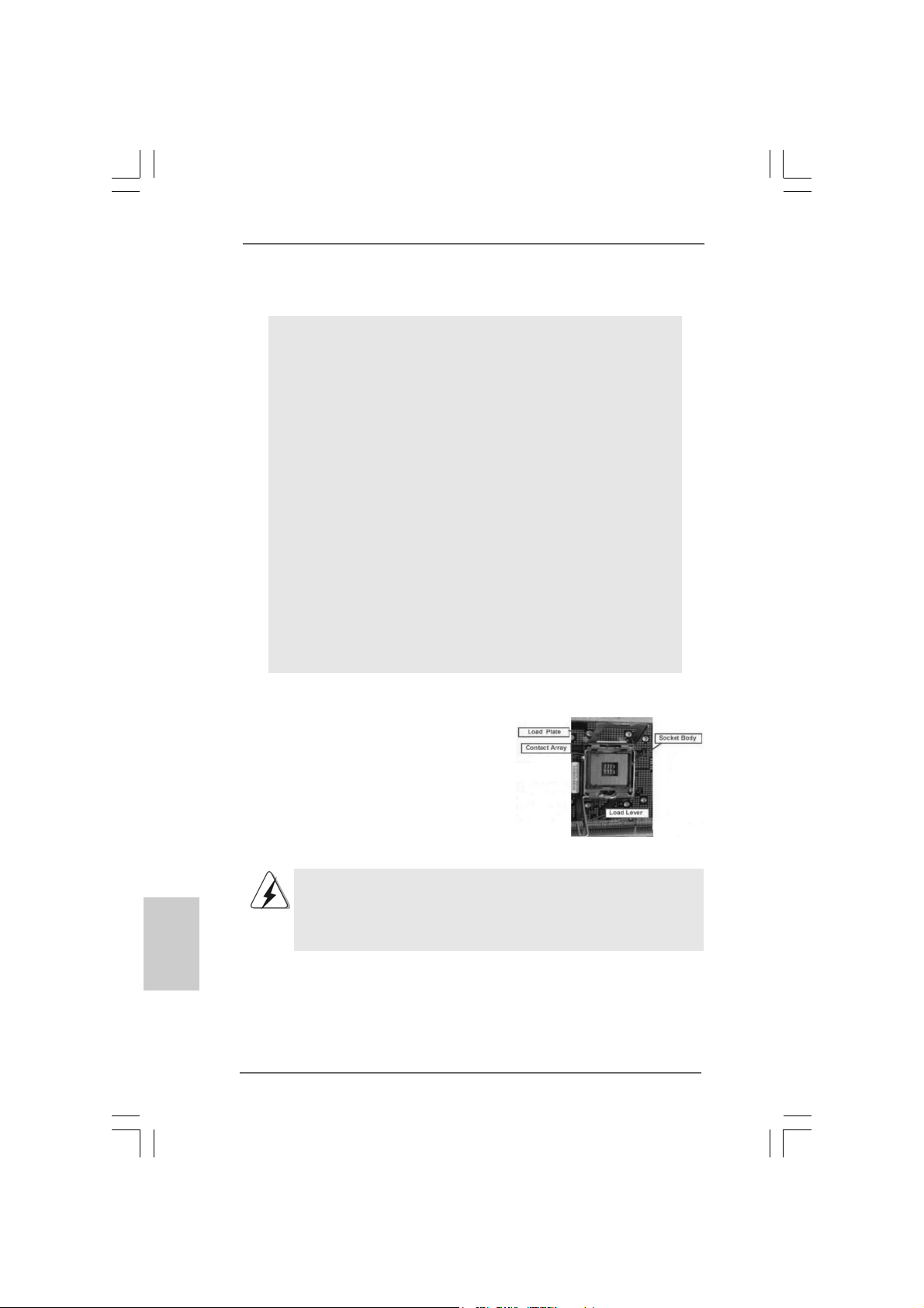
775-Pin Socket Overview
Before you insert the 775-LAND CPU into the socket, please check if
the CPU surface is unclean or if there is any bent pin on the socket.
Do not force to insert the CPU into the socket if above situation is
found. Otherwise, the CPU will be seriously damaged.
ASRock 775XFire-eSATA2+ Motherboard
Page 11
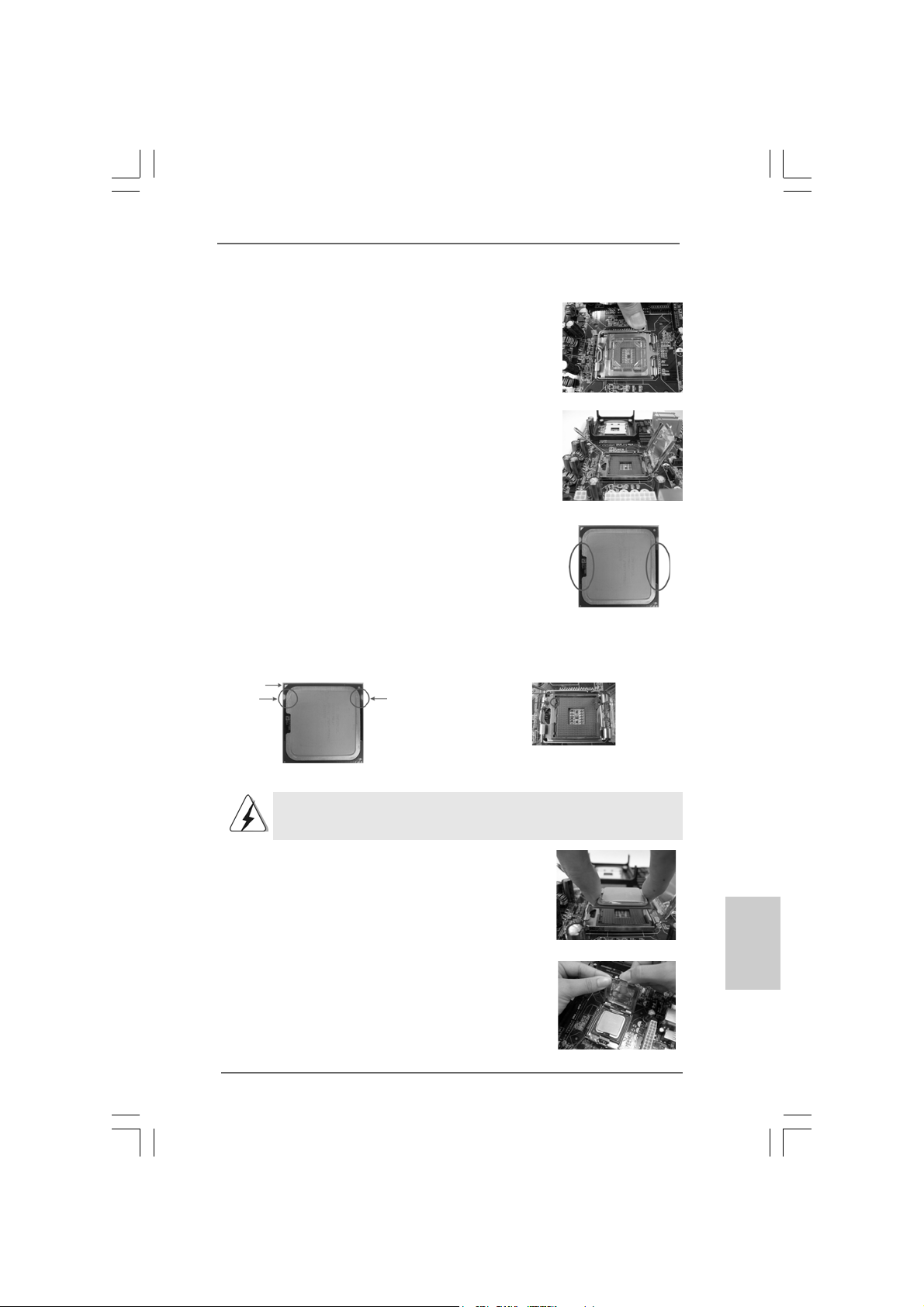
Step 1. Open the socket:
Step 1-1. Disengaging the lever by depressing
down and out on the hook to clear
retention tab.
Step 1-2. Rotate the load lever to fully open po-
sition at approximately 135 degrees.
Step 1-3. Rotate the load plate to fully open po-
sition at approximately 100 degrees.
Step 2. Insert the 775-LAND CPU:
Step 2-1. Hold the CPU by the edges where are
marked with black lines.
Step 2-2. Orient the CPU with IHS (Integrated
Heat Sink) up. Locate Pin1 and the two
orientation key notches.
Pin1
orientation
key notch
orientation
key notch
Pin1
alignment key
black line
black line
alignment key
775-LAND CPU
For proper inserting, please ensure to match the two orientation key
notches of the CPU with the two alignment keys of the socket.
Step 2-3. Carefully place the CPU into the socket
by using a purely vertical motion.
Step 2-4. Verify that the CPU is within the socket
and properly mated to the orient keys.
Step 3. Remove PnP Ca p (Pick a nd Place Cap):
Use your left hand index finger and thumb to
support the load plate edge, engage PnP cap
with right hand thumb and peel the cap from the
socket while pressing on center of PnP cap to
assist in removal.
ASRock 775XFire-eSATA2+ Motherboard
775-Pin Socket
1111
11
1111
EnglishEnglish
EnglishEnglish
English
Page 12
1. It is recommended to use the cap tab to handle and avoid kicking
off the PnP cap.
2. This cap must be placed if returning the motherboard for after
service.
Step 4. Close the socket:
Step 4-1. Rotate the load plate onto the IHS.
Step 4-2. While pressing down lightly on load
plate, engage the load lever.
Step 4-3. Secure load lever with load plate tab
under retention tab of load lever.
2.22.2
Installation of CPU Fan and HeatsinkInstallation of CPU Fan and Heatsink
2.2
Installation of CPU Fan and Heatsink
2.22.2
Installation of CPU Fan and HeatsinkInstallation of CPU Fan and Heatsink
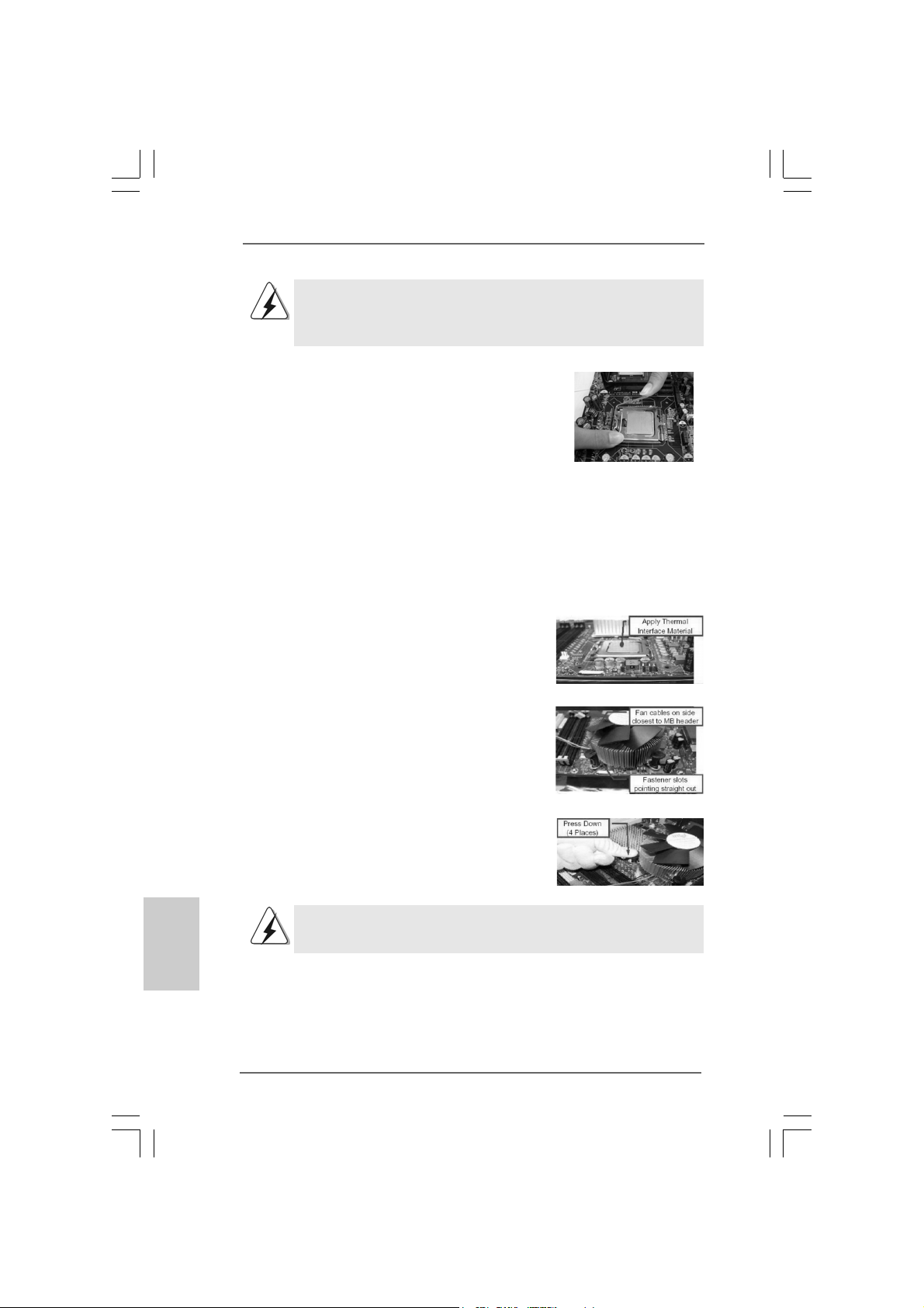
For proper installation, please kindly refer to the instruction manuals of your CPU fan
and heatsink.
Below is an example to illustrate the installation of the heatsink for 775-LAND CPU.
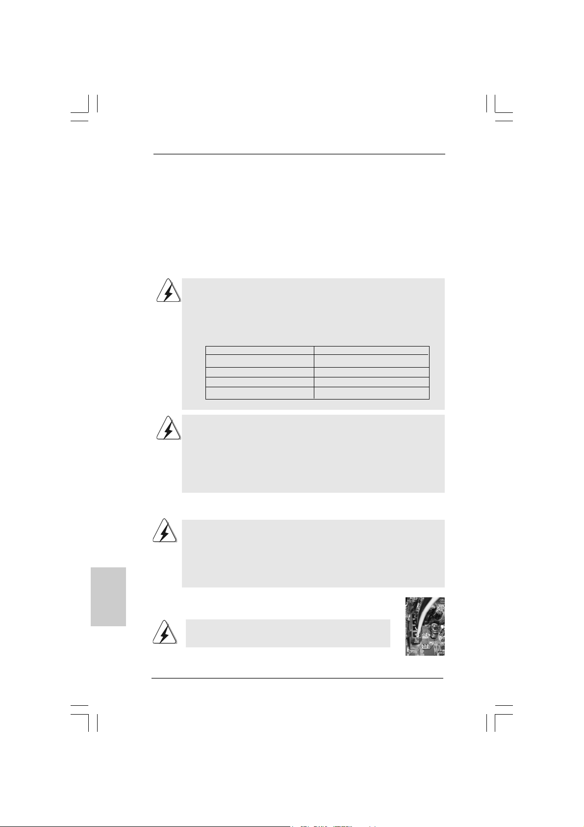
Step 1. Apply thermal interface material onto center
of IHS on the socket surface.
Step 2. Place the heatsink onto the socket. Ensure
fan cables are oriented on side closest to the
CPU fan connector on the motherboard
(CPU_FAN1, see page 2, No. 6).
Step 3. Align fasteners with the motherboard
throughholes.
Step 4. Rotate the fastener clockwise, then press
down on fastener caps with thumb to install
and lock. Repeat with remaining fasteners.
English
EnglishEnglish
EnglishEnglish
1212
12
1212
If you press down the fasteners without rotating them clockwise,
the heatsink cannot be secured on the motherboard.
Step 5. Connect fan header with the CPU fan
connector on the motherboard.
Step 6. Secure excess cable with tie-wrap to ensure
cable does not interfere with fan operation or
contact other components.
ASRock 775XFire-eSATA2+ Motherboard
Page 13
2.3 Installation of Memory Modules (DIMM)2.3 Installation of Memory Modules (DIMM)
2.3 Installation of Memory Modules (DIMM)
2.3 Installation of Memory Modules (DIMM)2.3 Installation of Memory Modules (DIMM)
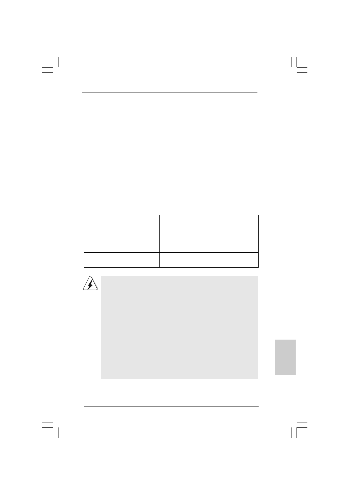
775XFire-eSATA2+ motherboard provides four 240-pin DDRII (Double Data Rate
II) DIMM slots, a nd supports Dual Channel Memory Technology. For dual channel
configuration, you always need to install identical (the same brand, speed,
size and chip-type) DDRII DIMM pair in the slots of the sa me color. In other words,
you have to install identical DDRII DIMM pair in Dual Channel A (DDRII_1 and
DDRII_3; Yellow slots; see p.2 No.7) or identical DDRII DIMM pair in Dual Chan-
nel B (DDRII_2 and DDRII_4; Orange slots; see p.2 No.8), so that Dual Channel
Memory Technology can be activated. This motherboard also allows you to
install four DDRII DIMMs for dual channel configuration, and please install iden-
tical DDRII DIMMs in all four slots. You may refer to the Dual Channel Memory
Configuration Table below.
Dual Channel Memory Configurations
(DS: Double Side, SS: Single Side)
DDRII_1 DDRII_2 DDRII_3 DDRII_4
(Yellow Slot) (Orange Slot) (Yellow Slot) (Orange Slot)
2 memory modules SS X SS X
2 memory modules DS X DS X
2 memory modules X SS X SS
2 memory modules X DS X DS
4 memory modules SS SS SS SS
1. If you want to install two memory modules, for optimal compatibility
and reliability, it is recommended to install them in the slots of the
same color. In other words, install them either in the set of yellow
slots (DDRII_1 and DDRII_3), or in the set of orange slots (DDRII_2
and DDRII_4).
2. If only one memory module or three memory modules are installed
in the DDRII DIMM slots on this motherboard, it is unable to activate
the Dual Channel Memory T e chnology.
3. If a pair of memory modules is NOT installed in the same Dual
Channel, for exa mple, in stalling a pair of memory module s in DD RII_1
and DDRII_2, it is unable to activate the Dual Channel Memory
Technology .
4. It is not allowed to install a DDR memory module into DDRII slot;
otherwise, this motherboard and DIMM may be damaged.
ASRock 775XFire-eSATA2+ Motherboard
1313
13
1313
EnglishEnglish
EnglishEnglish
English
Page 14
Recommended Memory Configurations
(DS: Double Side, SS: Single Side)
DDRII_1 DDRII_2 DDRII_3 DDRII_4
(Yellow Slot) (Orange Slot) (Yellow Slot) (Orange Slot)
1 memory module DS/SS* X X X
2 memory modules DS/SS X DS/SS X
2 memory modules X DS/SS X DS/SS
3 memory modules SS SS DS/SS X
4 memory modules SS SS SS SS
* If you only install one memory module, you can install it to any one of the four slots.
These two TRANSCEND memory modules can only be supported under the
following conditions:
DRAM SIZE TYPE CELL CELL NO. SINGLE SIDE /
VENDOR (MB) VENDOR DOUBLE SIDE
TRANSCEND 256 DDRII533 SAMSUNG K4T56083QF-ZCD5 SINGLE SIDE
TRANSCEND 512 DDRII533 INFINEON HYB18T512800AF37 SINGLE SIDE
1. If you plan to install one above me mory module, you can install it to any DDRII
slot of this motherboard.
2. If you plan to install two above memory modules, it is recommended to
install them either in the set of yellow slots (DDRII_1 a nd DD RII_3), or in the set
of orange slots (DDRII_2 and DDRII_4).
3. This motherboard does not support three or four above memory modules.
English
EnglishEnglish
EnglishEnglish
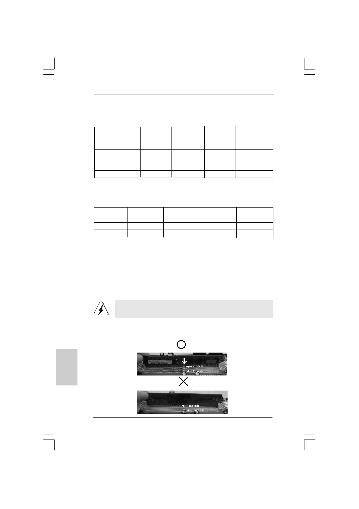
Installing a DIMMInstalling a DIMM
Installing a DIMM
Installing a DIMMInstalling a DIMM
Please make sure to disconnect power supply before adding or
removing DIMMs or the system components.
Step 1. Unlock a DIMM slot by pressing the retaining clips outward.
Step 2. Align a DIMM on the slot such that the notch on the DIMM matches the break
on the slot.
1414
14
1414
ASRock 775XFire-eSATA2+ Motherboard
Page 15
The DIMM only fits in one correct orientation. It will cause permanent damage
to the motherboard and the DIMM if you force the DIMM into the slot at
incorrectorientation.
Step 3. Firmly insert the DIMM into the slot until the retaining clips at both ends fully
snap back in place and the DIMM is properly seated.
2.4 Expansion Slots (PCI, PCI Express, and AGI Express2.4 Expansion Slots (PCI, PCI Express, and AGI Express
2.4 Expansion Slots (PCI, PCI Express, and AGI Express
2.4 Expansion Slots (PCI, PCI Express, and AGI Express2.4 Expansion Slots (PCI, PCI Express, and AGI Express
Slots) Slots)
Slots)
Slots) Slots)
There are 3 PCI slots, 2 PCI Express slots, and 1 AGI Express slot (PCI Express x4)
on this motherboard.
PCI slots: PCI slots are used to install expansion cards that have the 32-bit PCI
interface.
PCIE Slots: PCIE1 (PCIE x16 slot) is used for PCI Express cards with x16 lane
width graphics cards.
PCIE2 (PCIE x1 slot) is used for PCI Express cards, such as
Gigabit LAN card, SATA2 card, etc.
AGI Express slot (PCI Express x4):
AGI Express slot (PCI Express x4) is used to install PCI Express expan-
sion cards. For the information of the compatible PCI Express VGA cards,
please refer to the “Supported PCI Express VGA Card List for AGI Ex-
press Slot (PCI Express x4)” on page 9.
Installing an expansion cardInstalling an expansion card
Installing an expansion card
Installing an expansion cardInstalling an expansion card
Step 1. Before installing the expansion card, please make sure that the power
supply is switched off or the power cord is unplugged. Please read the
documentation of the expansion card and make necessary hardware
settings for the card before you start the installation.
Step 2. Remove the bracket facing the slot that you intend to use. Keep the screws
for later use.
Step 3. Align the card connector with the slot and press firmly until the card is
completely seated on the slot.
Step 4. Fasten the card to the chassis with screws.
ASRock 775XFire-eSATA2+ Motherboard
1515
15
1515
EnglishEnglish
EnglishEnglish
English
Page 16
TMTM
TM
2.5 CrossFire2.5 CrossFire
2.5 CrossFire
2.5 CrossFire2.5 CrossFire
TMTM
Operation Guide Operation Guide
Operation Guide
Operation Guide Operation Guide
This motherboard supports CrossFireTM feature. CrossFireTM technology offers the
most advantageous mea n s availa ble of combining multiple high perf ormance Gra phics
Processing Units (GPU) in a single PC. Combining a range of different operating
modes with intelligent software design and an innovative interconnect mechanism,
CrossFireTM enables the highest possible level of performance and image quality in
any 3D application. Currently CrossFireTM feature is only supported with Windows
XP with Service Pack 2; it may be supported with other OS in the future.
What graphics cards work with CrossFireTM?
A complete CrossFireTM system requires a CrossFireTM Ready motherboard,
a CrossFireTM Edition graphics card and a compatible standard Radeon
(CrossFireTM Ready) graphics card from the same series, or two CrossFire
Ready cards if they are software enabled. This applies to cards from ATI or
any of its partners.
Cards For AGI Express Slot Cards For PCI Express Slot
Radeon X1800 Series Radeon X1800 CrossFireTM Edition
Radeon X1600 Series Radeon X1600 Series
Radeon X1300 Series Radeon X1300 Series
Radeon X850 Series Radeon X850 CrossFireTM Edition
1. If a customer incorrectly configures their system they will not see the
performance benefits of CrossFireTM. All three CrossFireTM components, a
CrossFireTM Ready graphics card, a CrossFireTM Ready motherboard and
a CrossFireTM Edition co-processor graphics card, must be installed
correctly to benefit from the CrossFireTM multi-GPU platform.
2. If you pair a 12-pipe CrossFireTM Edition card with a 16-pipe card, both
cards will operate as 12-pipe cards while in CrossFireTM mode.
TM
English
EnglishEnglish
EnglishEnglish
1616
16
1616
TMTM
TM
Enjoy the benefit of CrossFireEnjoy the benefit of CrossFire
Enjoy the benefit of CrossFire
Enjoy the benefit of CrossFireEnjoy the benefit of CrossFire
Currently, ATI ha s rele ased Radeon X850XT, X1800XT, X1300, a nd X1600
CrossFireTM cards, which require different methods to enable CrossFire
feature. In the below procedures, we use Radeon X850XT as the example
graphics card. For other CrossFireTM cards that ATI has released or will
release in the future, please refer to ATI graphics card manuals for detailed
installation guide.
TMTM
Step 1. Connect to the system power supply. Please connect a hard
disk power connector to SLI/XFIRE Power connector.
It is recommended to use 500-Watt power supply or greater
to perform the benefit of CrossFireTM feature.
ASRock 775XFire-eSATA2+ Motherboard
TM
Page 17
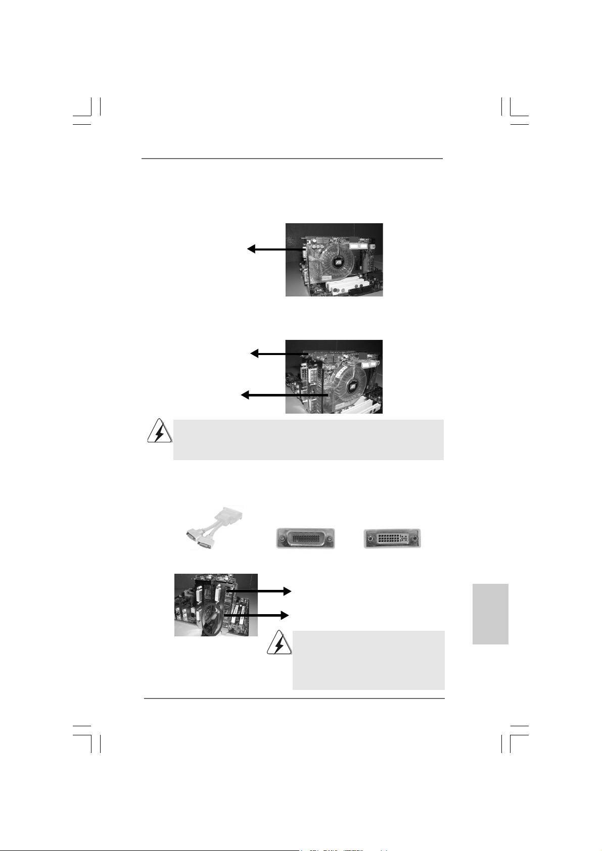
Step 2. Install the standard Radeon (CrossFireTM Ready) graphics card to AGI Ex-
press slot (PCI Express x 4). For the proper installation procedures, please
refer to section “Expansion Slots”.
Standard Radeon
(CrossFireTM Ready)
graphics card
Step 3. Install the Radeon CrossFireTM Edition graphics card to PCI Express x 16
slot. For the proper installation procedures, please refer to section “Expansion Slots”.
Radeon CrossFire
Edition graphics card
Standard Radeon
(CrossFireTM Ready)
graphics card
You are allowed to install two CrossFireTM Edition graphics cards to both slots,
or you may use one CrossFire
standard Radeon (CrossFireTM Ready) graphics card from the same series.
TM
TM
Edition graphics cards and a compatible
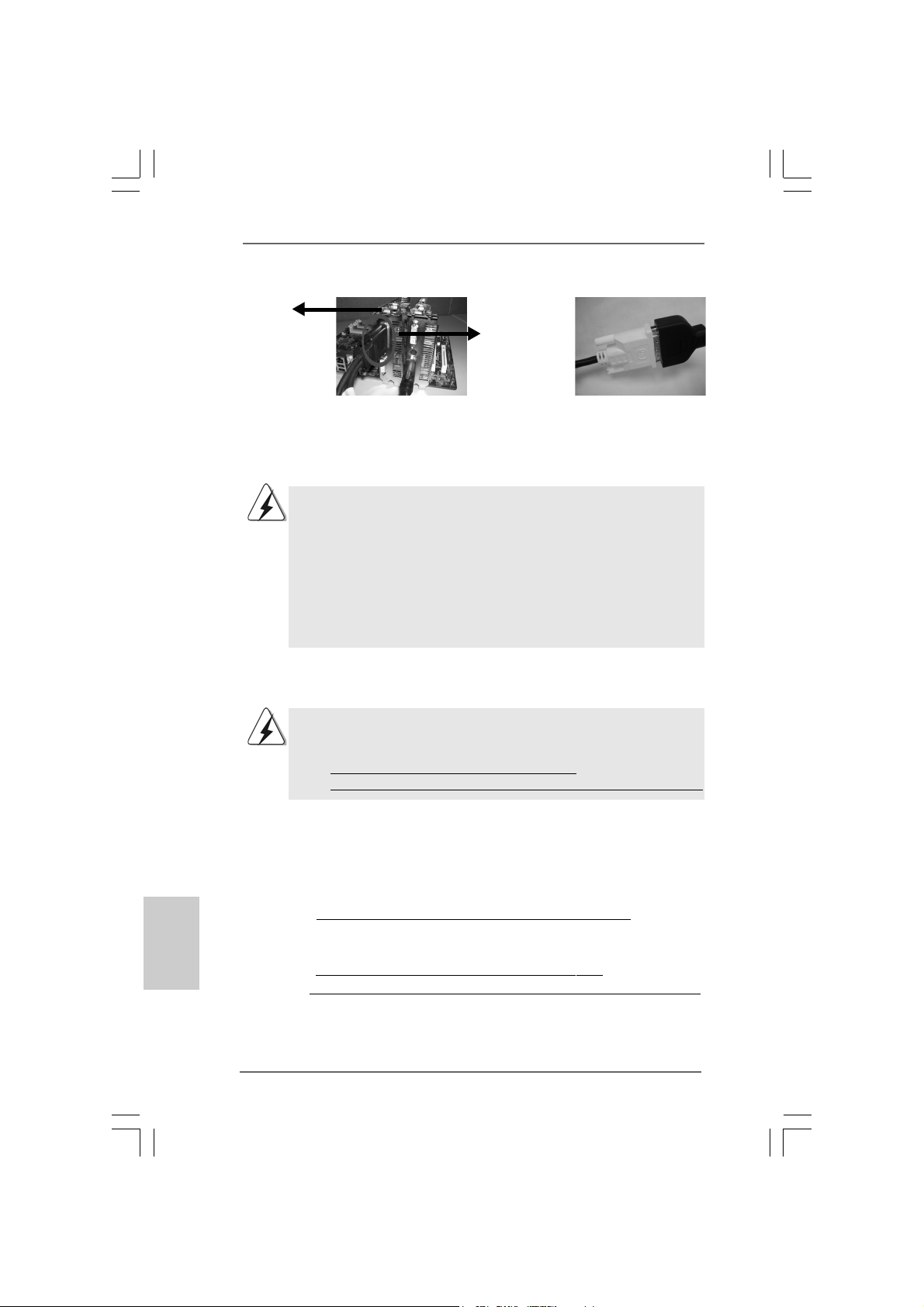
Step 4. Correctly connect the DVI-DMS cable to the monitor connector and two
graphics cards that you install. (If you install two standard Radeon
(CrossFireTM Ready) graphics cards to this motherboard, please skip this
step.)
DVI-DMS cable DMS connector
Standard Radeon (CrossFireTM Ready)
graphics card
DVI connector
D VI connector
Connect the DVI-DMS
cable to DVI connector of
the compatible standard
Radeon (CrossFire
Ready) graphics card.
TM
ASRock 775XFire-eSATA2+ Motherboard
There are two DVI connectors on the
standard Radeon (CrossFire
graphics card. Please connect the DVI-DMS
cable to the correct DVI connector; otherwise
, the graphics card will not work.
TM
Ready)
1717
17
1717
EnglishEnglish
EnglishEnglish
English
Page 18
Radeon
TM
CrossFire
Edition graphics
card
DMS
connector
English
EnglishEnglish
EnglishEnglish
Connect the DVI-DMS
cable to DMS connector
of the CrossFire
graphics card.
If you install two CrossFireTM Edition graphics cards to this motherboard, please
connect one end of DVI-DMS cable to the monitor, another end to DMS of one
of the CrossFireTM Edition graphics cards to PCIE1 slot (PCI Express x 16), a n d
the other end to DVI of another CrossFireTM Edition graphics card to AGI
Express slot (PCI Express x 4). If you install one CrossFireTM Edition graphics
card and one compatible standard Radeon (CrossFireTM Ready) graphics card
to this motherboard, please connect one end of DVI-DMS cable to the monitor,
another end to DMS of the CrossFireTM Edition graphics card, a nd the other end
to DVI of the compatible standard Radeon (CrossFireTM Ready) graphics card.
TM
Edition
Connect the DVI-DMS
cable to the monitor
connector.
Step 5. Power on your computer and boot into OS.
Step 6. Remove the ATI driver if you have any VGA driver installed in your system.
The Catalyst Uninstaller is an optional download. We recommend using this
utility to uninstall any previously installed Catalyst drivers prior to installation.
Please visit this website for the driver:
http://support.ati.com/ics/support/DLRedirect.asp?
fileIDExt=050553d40196ef109fff37cbb40aaf28&accountID=737&deptID=894
Step 7. Install the required drivers to your system. Please visit the websites below
for installing the drivers that ATI recommends:
A. ATI recommends Windows XP Service Pack 2 or higher to be installed
(If you have Windows XP Service Pack 2 or higher installed in your
system, there is no need to download it again):
http://www.microsoft.com/windowsxp/sp2/default.mspx
B. You must have Microsoft .NET Framework installed prior to
downloading and installing the CATALYST Control Center:
http://www.microsoft.com/downloads/details.aspx?
FamilyId=262D25E3-F589-4842-8157-034D1E7CF3A3&displaylang=en
Step 8. Restart your computer.
1818
18
1818
ASRock 775XFire-eSATA2+ Motherboard
Page 19
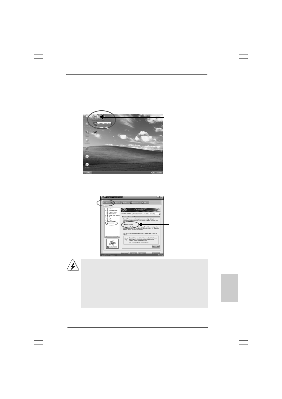
Step 9. Install the VGA card drivers to your system, and restart your computer.
Then you will find “ATI Catalyst Control Center” on your desktop (ATI
Catalyst driver should be version 5.10 or higher).
t
t
You will find “ATI Catalyst
Control Center” on your
desktop.
Step 10. Double-click “ATI Catalyst Control Center”. Click “View”, and select “Ad-
vanced View”. Click “CrossFire
TM
”, and then set the option “Enable
CrossFireTM” to “Yes”.
View
CrossFire
TM
Enable CrossFire
TM
If you install one Radeon CrossFireTM Edition graphics card a nd one compatible
standard Radeon (CrossFireTM Ready) graphics card to this motherboard but
not two Radeon CrossFireTM Edition graphics cards, please as well follow the
above steps. However, although you have selected the option “Enable
CrossFireTM”, the CrossFireTM function can not work actually. Your computer
will automatically reboot. After restarting your computer, please confirm whether
the option “Enable CrossFireTM” in “ATI Catalyst Control Center” is selected or
not; if not, please select it again, and then you are able to enjoy the benefit of
CrossFire
TM
feature.
Step 11. You can freely enjoy the benefit of CrossFireTM feature.
* CrossFireTM appearing here is a registered trademark of ATI Technologies Inc., and is used only
for identification or explanation and to the owners’ benefit, without intent to infringe.
ASRock 775XFire-eSATA2+ Motherboard
1919
19
1919
EnglishEnglish
EnglishEnglish
English
Page 20
2.6 Surround Display Feature2.6 Surround Display Feature
2.6 Surround Display Feature
2.6 Surround Display Feature2.6 Surround Display Feature
This motherboard supports Surround Display upgrade. With the external add-on
PCI Express VGA card, you can easily enjoy the benefits of Surround Display
feature. For the detailed instruction, please refer to the document at the following
path in the Support CD:
..\ Surround Display Information
2.7 Jumpers Setup2.7 Jumpers Setup
2.7 Jumpers Setup
2.7 Jumpers Setup2.7 Jumpers Setup
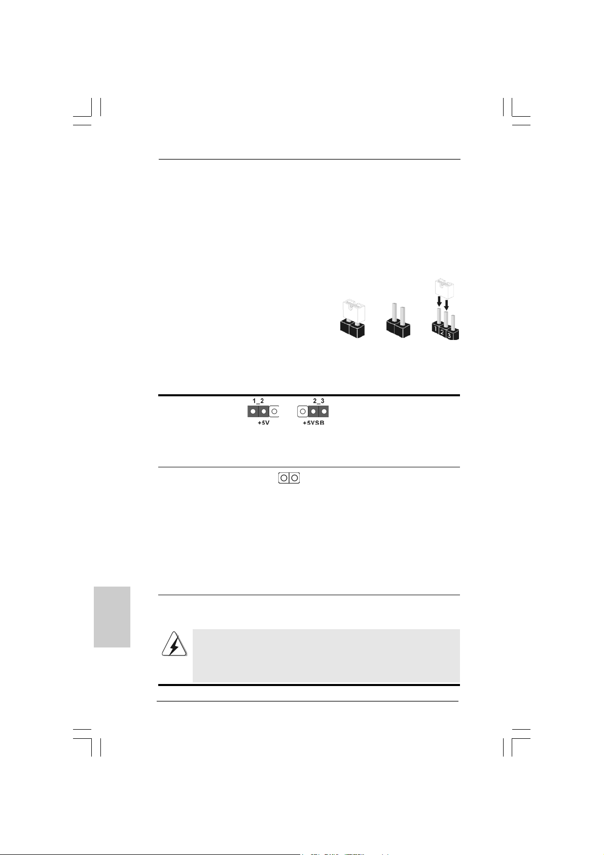
The illustration shows how jumpers are
setup. When the jumper cap is placed on
pins, the jumper is “Short”. If no jumper cap
is placed on pins, the jumper is “Open”. The
illustration shows a 3-pin jumper whose pin1
and pin2 are “Short” when jumper cap is
placed on these 2 pins.
Jumper Setting Description
PS2_USB_PWR1 Short pin2, pin3 to enable
(see p.2 No. 1) +5VSB (standby) for PS/2
Note: To select +5VSB, it requires 2 Amp and higher standby current provided by
power supply.
Clear CMOS
(CLRCMOS1, 2-pin jumper)
(see p.2 No. 1 1)
2-pin jumper
Short Open
or USB wake up events.
English
EnglishEnglish
EnglishEnglish
Note: CLRCMOS1 allows you to clear the data in CMOS. The data in CMOS includes
system setup information such as system password, date, time, and system
setup parameters. To clear and reset the system parameters to default setup,
please turn off the computer and unplug the power cord from the power
supply. After waiting for 15 seconds, use a jumper cap to short 2 pins on
CLRCMOS1 for 5 seconds.
2.8 Onboard Headers and Connectors2.8 Onboard Headers and Connectors
2.8 Onboard Headers and Connectors
2.8 Onboard Headers and Connectors2.8 Onboard Headers and Connectors
Onboard headers and connectors are NOT jumpers. Do NOT place
jumper caps over these headers and connectors. Placing jumper caps
over the headers and connectors will cause permanent damage of the
motherboard!
2020
20
2020
ASRock 775XFire-eSATA2+ Motherboard
Page 21
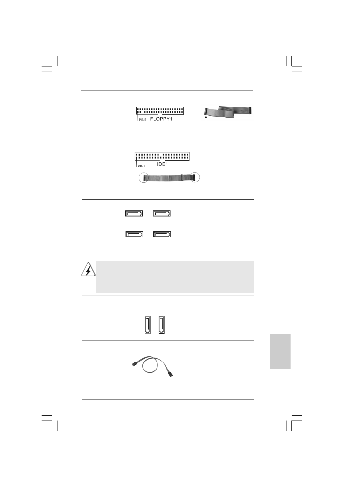
FDD connector
(33-pin FLOPPY1)
(see p.2 No. 25)
the red-striped side to Pin1
Note: Make sure the red-striped side of the cable is plugged into Pin1 side of the
connector.
Primary IDE connector (Blue)
(39-pin IDE1, see p.2 No. 10)
connect the blue end
to the motherboard
connect the black end
to the IDE devices
80-conductor ATA 66/100 cable
Note: Please refer t o t h e in struction of your IDE device vendor for the details.
Serial ATA II Connectors These four Serial AT A II
(SAT AII_BLUE (PORT0): (SATAII) connectors support
see p.2, No. 16) SATA data cables for internal
(SAT AII_BLACK (PORT1): storage devices. The current
see p.2, No. 15) SATA II interface allows up to
(SAT AII_RED (PORT2): 3.0 Gb/s data transfer rate.
see p.2, No. 13)
(SAT AII_ORANGE (PORT3):
see p.2, No. 14)
SATAII_RED (PORT2) a nd SATAII_ORANGE (PORT3) connectors can be
used for internal storage devices or be connected to eSATAII_BOTTOM
and eSA TAII_TOP connectors with corresponding color to support eSATAII
devices. Please read “eSATAII Interface Introduction” on page 27 for
details about eSATAII and eSATAII installation procedures.
SATAII_RED
(PORT2)
SATAII_BLUE
(PORT0)
SATAII_ORANGE
(PORT3)
SATAII_BLACK
(PORT1)
eSATA II Connectors These two eSATA II
(eSAT AII_TOP: see p.2, No. 35) connectors support SATA
(eSAT AII_BOTTOM: see p.2, No. 34) data cables for external
SATAII function. The current
eSATAII_BOTTOM
eSATAII_TOP
eSATA II interface allows up to
3.0 Gb/s data transfer rate.
Serial A TA (SA TA) Either end of the SATA data cable
Data Cable can be connected to the SATA /
SATAII hard disk or the SATAII
connector on the motherboard.
You can also use the SATA data
cable to connect SATAII connectors and eSATAII connectors
with corresponding color.
ASRock 775XFire-eSATA2+ Motherboard
2121
21
2121
EnglishEnglish
EnglishEnglish
English
Page 22
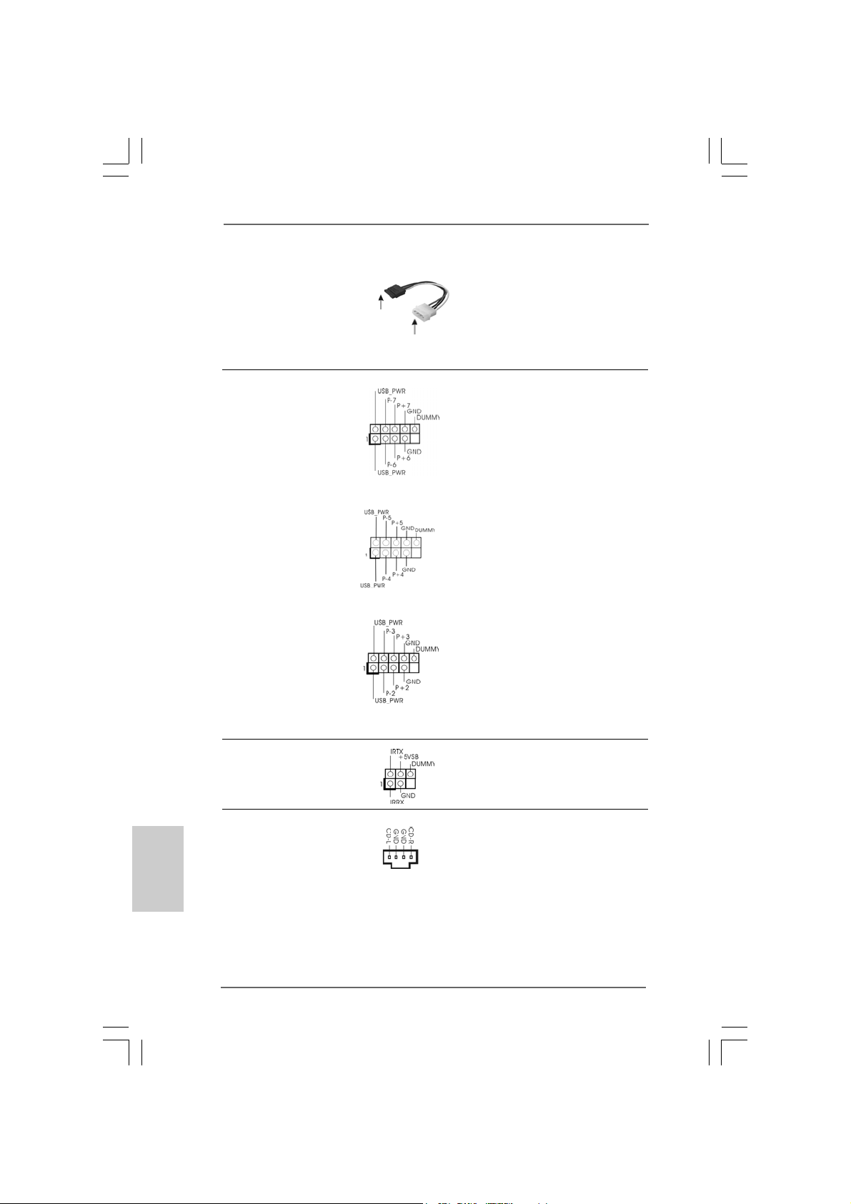
Serial ATA (SATA) Please connect the black end of
Power Cable SATA power cable to the power
(Optional) connector on each drive. Then
connect to the SAT A
HDD power connector
connect to the
power supply
connect the white end of SATA
power cable to the power
connector of the power supply.
USB 2.0 Headers Besides two default USB 2.0
(9-pin USB67) ports on the I/O panel, there are
(see p.2 No. 20) three USB 2.0 headers on this
motherboard. Each USB 2.0
header cansupport two USB
2.0 ports.
(9-pin USB45)
(see p.2 No. 22)
(9-pin USB23)
(see p.2 No. 23)
English
EnglishEnglish
EnglishEnglish
2222
22
2222
Infrared Module Header This header supports an
(5-pin IR1) optional wireless transmitting
(see p.2 No. 24) and receiving infrared module.
Internal Audio Connectors This connector allows you
(4-pin CD1) to receive stereo audio input
(CD1: see p.2 No. 28) from sound sources such as
CD1
a CD-ROM, D VD-ROM, TV
tuner card, or MPEG card.
ASRock 775XFire-eSATA2+ Motherboard
Page 23
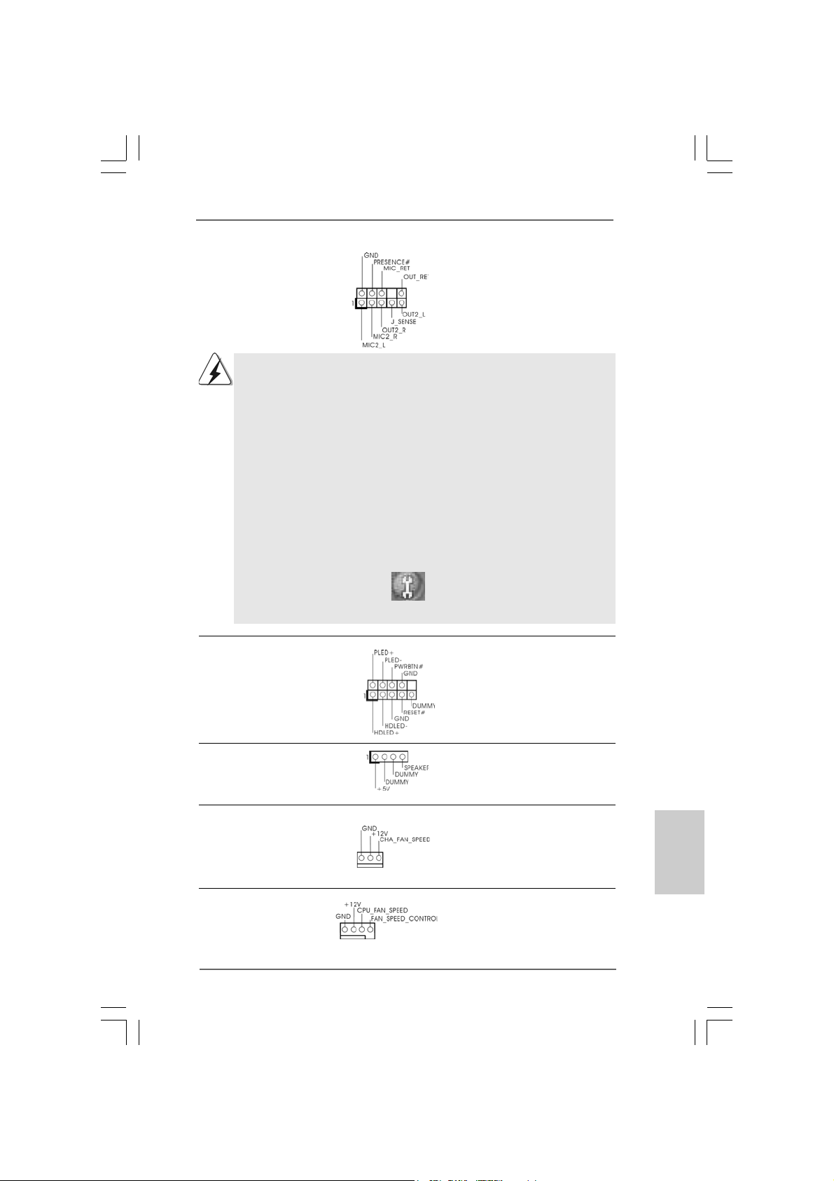
Front Panel Audio Header This is an interface for front
(9-pin HD_AUDIO1) panel audio cable that allows
(see p.2 No. 27) convenient connection and
control of audio devices.
1. High Definition Audio supports Jack Sensing, but the panel wire on the
chassis must support HDA to function correctly. Please follow the
instruction in our manual and chassis manual to install your system.
2. If you use AC’97 audio panel, please install it to the front panel audio
header as below:
A. Connect Mic_IN (MIC) to MIC2_L.
B. Connect Audio_R (RIN) to OUT2_R and Audio_L (LIN) to OUT2_L.
C. MIC_RET and OUT_RET are for HD audio panel only. You don’t
need to connect them for AC’97 audio panel.
D. Enter BIOS Setup Utility. Enter Advanced Settings, and then select
Chipset Configuration. Set the Front Panel Control option from
[Auto] to [Enabled].
E. Enter Windows system. Click the icon on the lower right hand
taskbar to enter Realtek HD Audio Manager. Click “Audio I/O”, select
“Connector Settings” , choose “Disable front panel jack
detection”, and save the change by clicking “OK”.
System Panel Header This header accommodates
(9-pin PANEL1) several system front panel
(see p.2 No. 18) functions.
Chassis Speaker Header Please connect the chassis
(4-pin SPEAKER 1) speaker to this header.
(see p.2 No. 19)
Chassis Fan Connector Please connect a chassis fan
(3-pin CHA_FAN1) cable to this connector and
(see p.2 No. 17) match the black wire to the
ground pin.
CPU Fan Connector Please connect a CPU fan cable
(4-pin CPU_FAN1) to this connector and match
(see p.2 No. 6) the black wire to the ground pin.
ASRock 775XFire-eSATA2+ Motherboard
2323
23
2323
EnglishEnglish
EnglishEnglish
English
Page 24
English
EnglishEnglish
EnglishEnglish
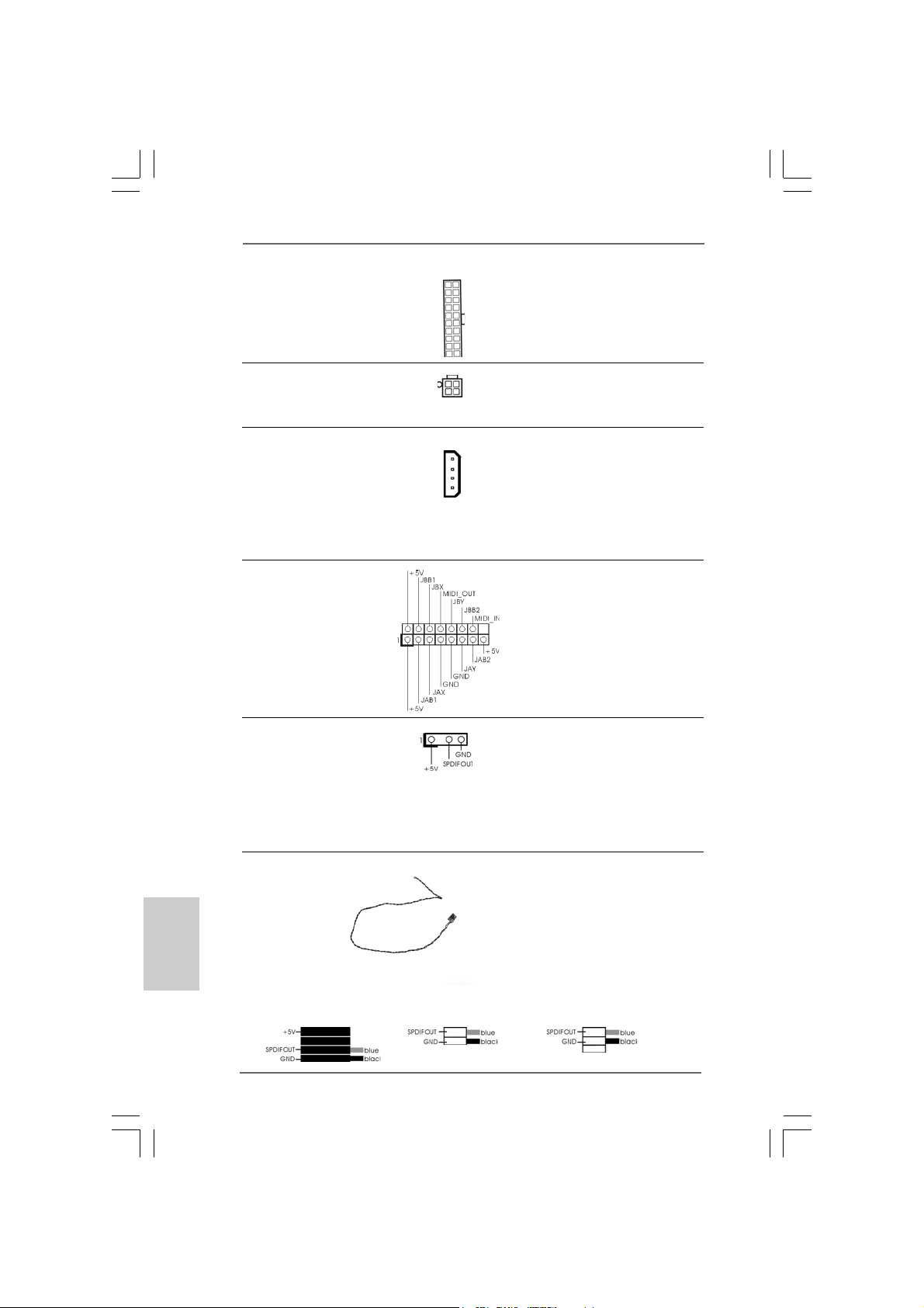
ATX Power Connector Please connect an ATX power
(20-pin ATXPW R1) supply to this connector.
(see p.2 No. 33)
ATX 12V Connector Please connect an ATX 12V
(4-pin A TX12V1) power supply to this connector.
(see p.2 No. 2)
SLI/XFIRE Power Connector It is not necessary to use this
(4-pin SLI/XFIRE_POWER1) connector, but please connect it
(see p.2 No. 3) with a hard disk power connecor
when two graphics cards are
SLI/XFIRE_POWER1
plugged to this motherboard at
the same time.
Game Port He ader Connect a Game cable to this
(15-pin GAME1) header if the Game port bracket
(see p.2 No. 26) is installed.
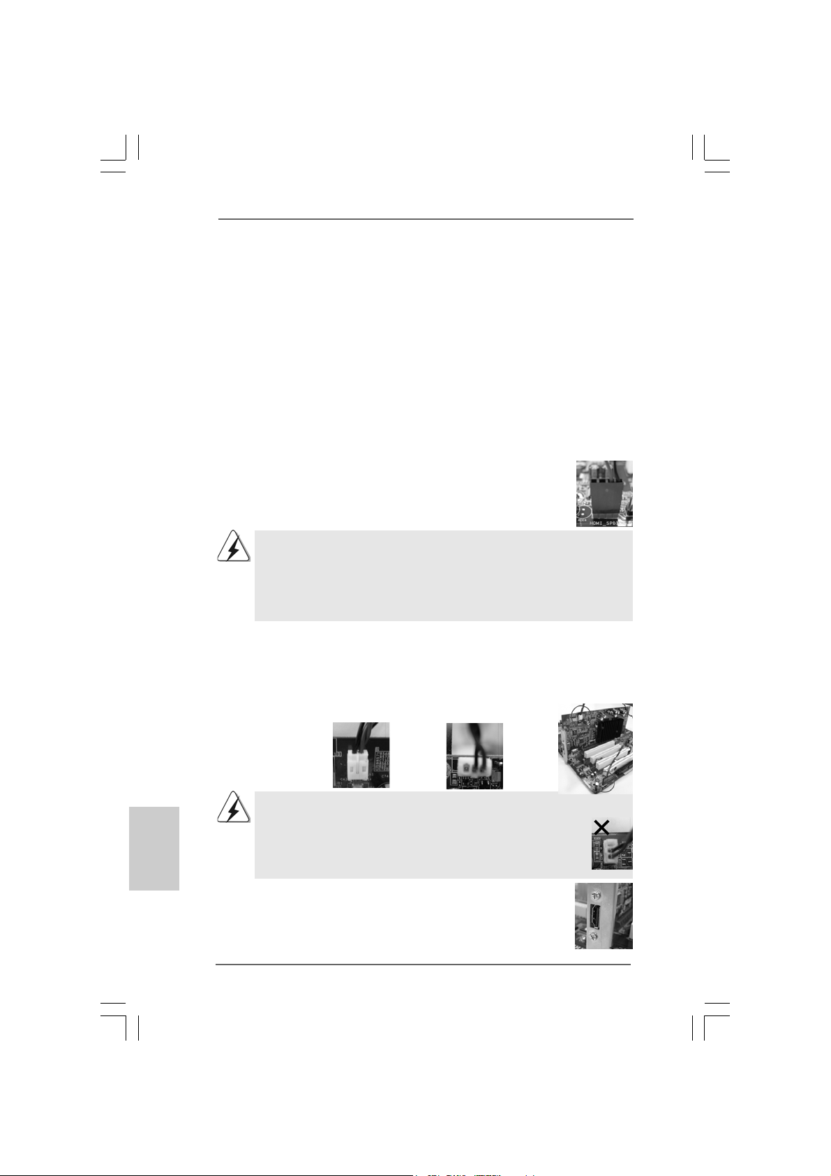
HDMI_SPDIF Header HDMI_SPDIF header, providing
(3-pin HDMI_SPDIF1) SPDIF audio output to HDMI V GA
(see p.2 No. 29) card, allows the system to
connect HDMI Digital TV/
projector/LCD devices. Please
connect the HDMI connector of
HDMI VGA card to this header.
HDMI_SPDIF Cable Please connect the bla ck end (A)
(Optional) of HDMI_SPDIF cable to the
C
B
A
HDMI_SPDIF header on the
motherboard. Then connect the
white end (B or C) of
HDMI_SPDIF cable to the
HDMI_SPDIF connector of HDMI
VGA card.
A. black end B. white end (2-pin) C. white end (3-pin)
2424
24
2424
ASRock 775XFire-eSATA2+ Motherboard
Page 25
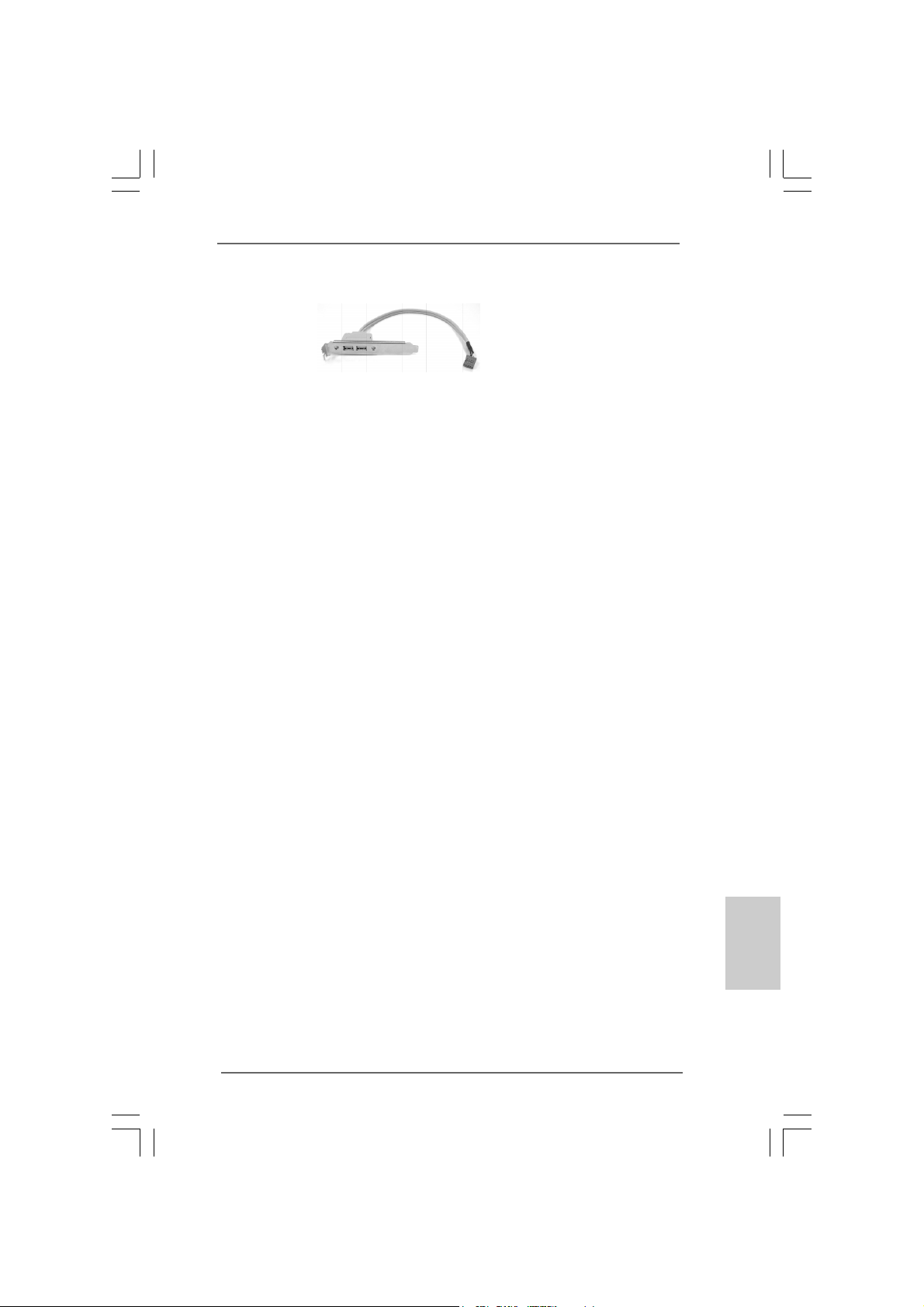
USB Bracket This USB bracket can support 2
additional USB 2.0 ports besides
the I/O panel. Please connect
the blue connector on the cable
of this USB bracket to the USB
2.0 header (USB23, USB45, or
USB67) and fasten the USB
bracket to the chassis with
screws.
ASRock 775XFire-eSATA2+ Motherboard
2525
25
2525
EnglishEnglish
EnglishEnglish
English
Page 26
English
EnglishEnglish
EnglishEnglish
2.9 HDMI_SPDIF Header Connection Guide2.9 HDMI_SPDIF Header Connection Guide
2.9 HDMI_SPDIF Header Connection Guide
2.9 HDMI_SPDIF Header Connection Guide2.9 HDMI_SPDIF Header Connection Guide
HDMI (High-Definition Multi-media Interfa ce) is an all-digital audio/video specification,
which provides an interface between any compatible digital audio/video source,
such as a set-top box, DVD player, A/V receiver and a compatible digital audio or
video monitor, such as a digital television (DTV). A complete HDMI system requires a
HDMI VGA card and a HDMI ready motherboard with a HDMI_SPDIF header. This
motherboard is equipped with a HDMI_SPDIF header, which provides SPDIF audio
output to HDMI VGA card, allows the system to connect HDMI Digital TV/projector/
LCD devices. To use HDMI function on this motherboard, please carefully follow the
below steps.
•
Step 1. Install the HDMI VGA card to the PCI Express Graphics slot on this
motherboard. For the proper installation of HDMI VGA card, please refer
to the installation guide on page 15.
Step 2. Connect the black end (A) of HDMI_SPDIF cable to the
HDMI_SPDIF header (HDMI_SPDIF1, yellow , see page 2, No.
29) on the motherboard.
Make sure to correctly connect the HDMI_SPDIF cable to the motherboard and the
HDMI VGA card according to the same pin definition. For the pin definition of
HDMI_SPDIF header and HDMI_SPDIF ca ble connectors, ple ase refer to page 24. For
the pin definition of HDMI_SPDIF connectors on HDMI VGA card, please refer to the
user manual of HDMI VGA card vendor. Incorrect connection may cause permanent
damage to this motherboard and the HDMI VGA card.
Step 3. Connect the white end (B or C) of HDMI_SPDIF cable to the HDMI_SPDIF
connector of HDMI VGA card. (There are two white ends (2-pin and 3-pin)
on HDMI_SPDIF cable. Please choose the appropriate white end a ccording
to the HDMI_SPDIF connector of the HDMI VGA card you install. Currently,
the HDMI_SPDIF connector of HDMI V GA card with A TI chi p is 3-pin (C), a nd
the HDMI_SPDIF connector of HDMI VGA card with other
vendor’s chip
is 2-pin (B).)
white end
(2-pin) (B)
Please do not connect the white end of HDMI_SPDIF cable to the wrong connector
of HDMI VGA card or other VGA card. Otherwise, the motherboard and the
VGA card may be damaged. For example, this picture shows the wrong
example of connecting HDMI_SPDIF cable to the fan connector of PCI
Express VGA card. Please refer to the VGA card user manual for
connector usage in advance.
white end
(3-pin) (C)
Step 4. Connect the HDMI output connector on HDMI VGA card to
HDMI device, such as HDTV. Please refer to the user manual
of HDTV and HDMI VGA card vendor for detailed connection
procedures.
Step 5. Install HDMI VGA card driver to your system.
2626
26
2626
ASRock 775XFire-eSATA2+ Motherboard
Page 27
2.10 eSA2.10 eSA
2.10 eSA
2.10 eSA2.10 eSA
What is eSATAII?
This motherboard supports eSATAII interface, the external SATAII specification.
eSATAII allows you to enjoy the SATAII function provided by the I/O of your
computer, offering the high speed data transfer rate up to 3.0Gb/s, and the
convenient mobility like USB. eSATAII is equipped with Hot Plug capability that
enables you to exchange drives easily. For example, with eSATAII interface, you
may simply plug your eSATAII hard disk to the eSATAII ports instead of opening
your chassis to exchange your SATAII hard disk. Currently, on the market, the
data transfer rate of USB 2.0 is up to 480Mb/s, and for IEEE 1394 is up to 400Mb/
s. However, eSATAII provides the data transfer rate up to 3000Mb/s, which is
much higher than USB 2.0 and IEEE 1394, and still keeps the convenience of Hot
Plug feature. Therefore, on the basis of the advantageous transfer speed and the
facilitating mobile capability, in the near future, eSATAII will replace USB 2.0 and
IEEE 1394 to be a trend for external interface.
How to install eSATAII?
TT
AII InterAII Inter
T
AII Inter
TT
AII InterAII Inter
face Introductionface Introduction
face Introduction
face Introductionface Introduction
SATAII_RED (PORT2) a nd
SAT AII_ORANGE (POR T3)
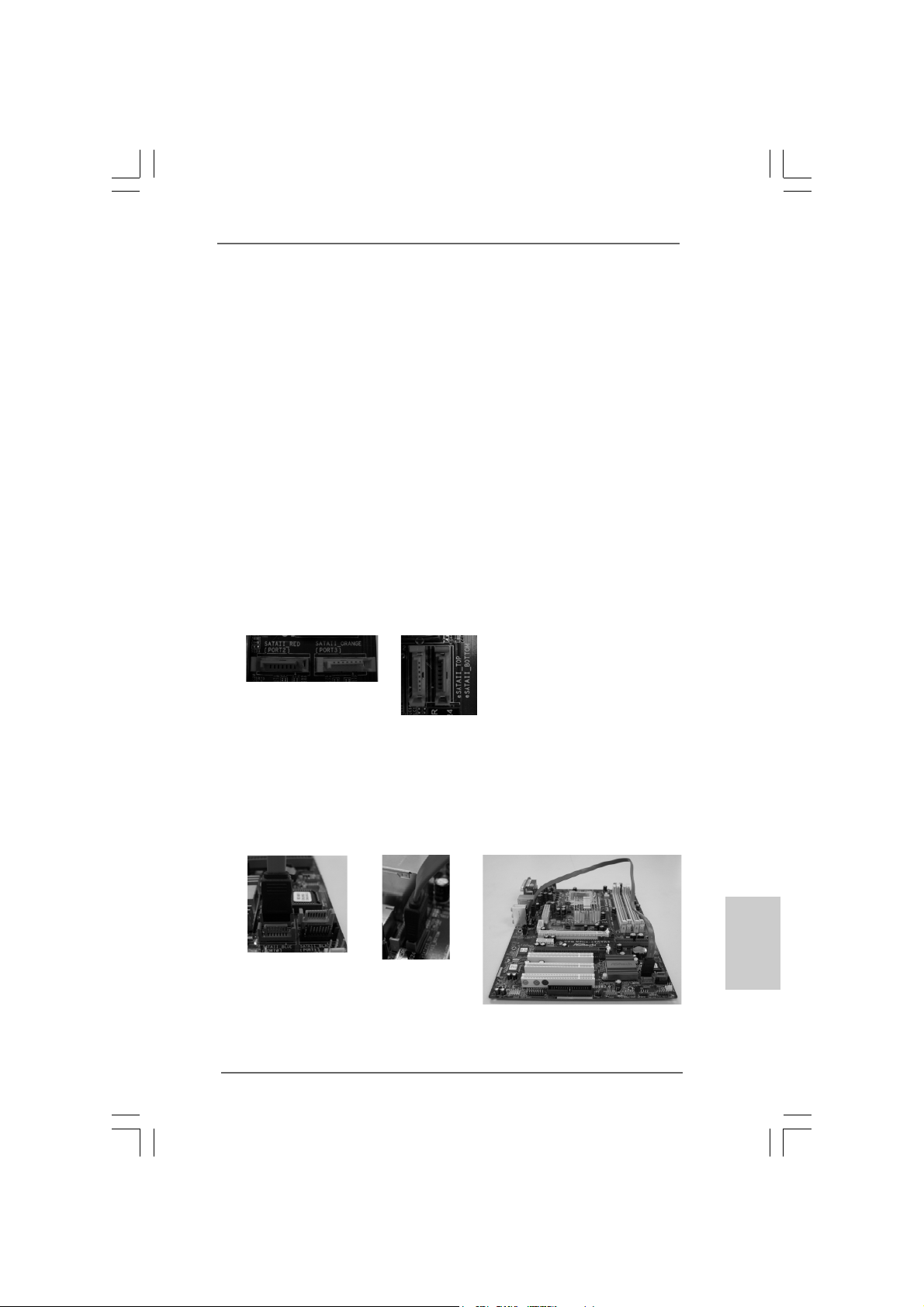
1. If you just plan to install one eSATAII device to this motherboard, it is recommended to enable the bottom eSATAII port of the I/O shield. In order to enable
the bottom eSATAII port of the I/O shield, you need to connect the red SATAII
connector (SATAII_RED; see p.2 No.13) and the red eSATAII connector
(eSATAII_BOTTOM; see p.2 No.34) with a SATA data cable first. Then the
bottom eSATAII port of the I/O shield is enabled.
Connect the SATA
data cable to the red
SATAII connector
(SATAII_RED (PORT2))
ASRock 775XFire-eSATA2+ Motherboard
Connect the SATA
data cable to the red
eSATAII connector
(eSATAII_BOTTOM)
eSAT AII_T OP and
eSATAII_BOTTOM
2727
27
2727
EnglishEnglish
EnglishEnglish
English
Page 28
2. If you plan to install two eSATAII devices to this motherboard, you need to
enable both the top and the bottom eSATAII ports of the I/O shield. In order to
enable the top and the bottom eSATAII ports of the I/O shield, you have to
connect the red SATAII connector (SATAII_RED; see p.2 No.13) and the red
eSATAII connector (eSATAII_BOTTOM; see p.2 No.34) with a SATA data
cable first, and then connect the orange SATAII connector (SATAII_ORANGE;
see p.2 No.14) and the orange eSATAII connector (eSATAII_TOP; see p.2 No.
35) with another SATA data cable. After that, both the top and the bottom
eSATAII ports of the I/O shield are enabled.
Connect the SATA
data cables to both
red SATAII connector
(SATAII_RED (PORT2))
and orange SATAII
connector (SATAII_
ORANGE (PORT3))
Please make sure to correctly connect the SATAII and eSATAII connectors
with corresponding color so that the eSATAII function will work successfully.
Connect the SATA
data cables to both
red eSATAII connector
(eSATAII_BOTTOM)
and orange eSATAII
connector (eSATAII_TOP)
English
EnglishEnglish
EnglishEnglish
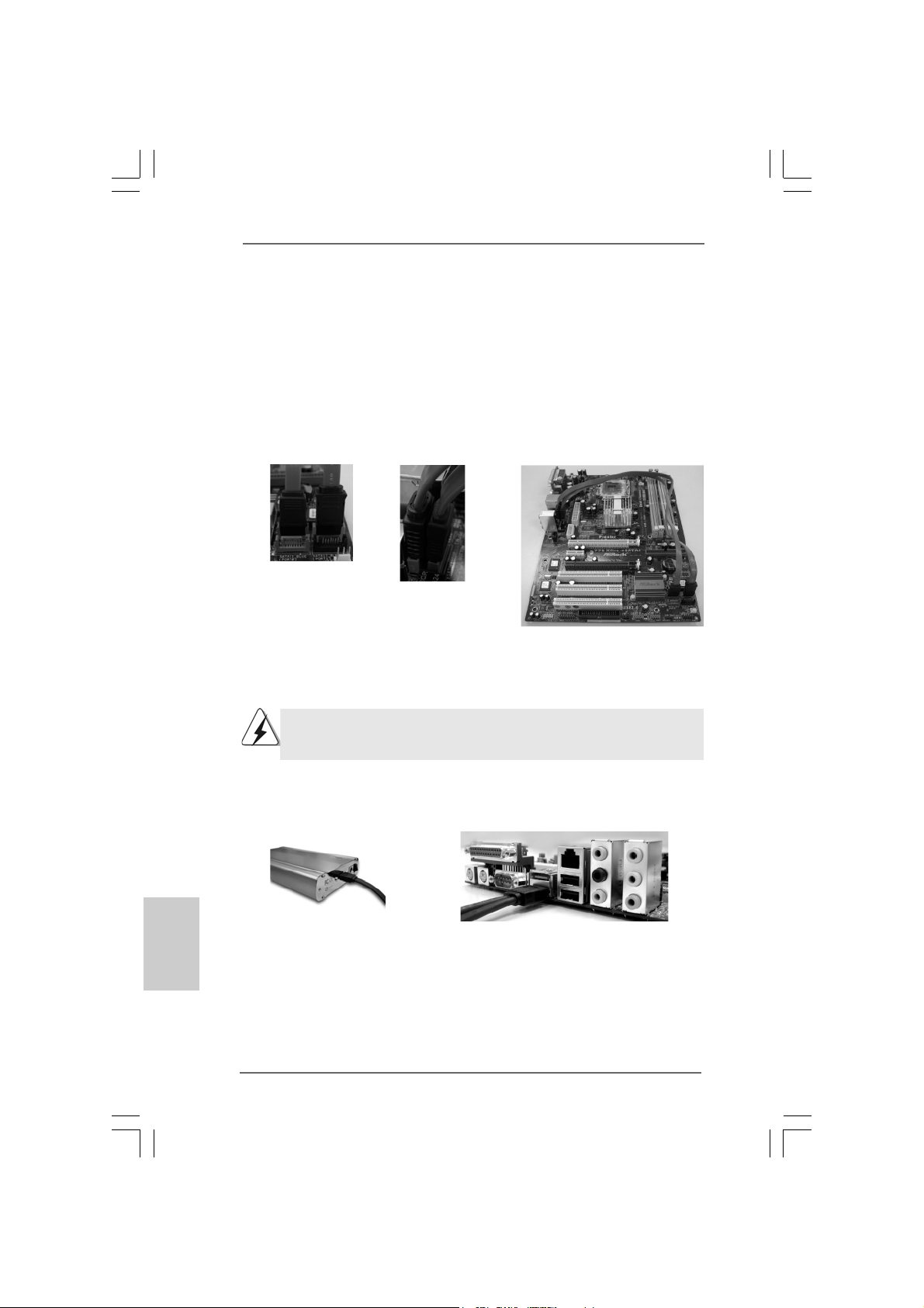
3. Use the eSATAII device cable to connect eSATAII device and the eSATAII port
of the I/O shield according to the eSATAII connector that you connect the
SATA data cable.
Connect the other end of the eSATAII
device cable to eSATAII port of the I/O
shield
2828
28
2828
Connect one end of the eSATAII
device cable to eSATAII device
ASRock 775XFire-eSATA2+ Motherboard
Page 29
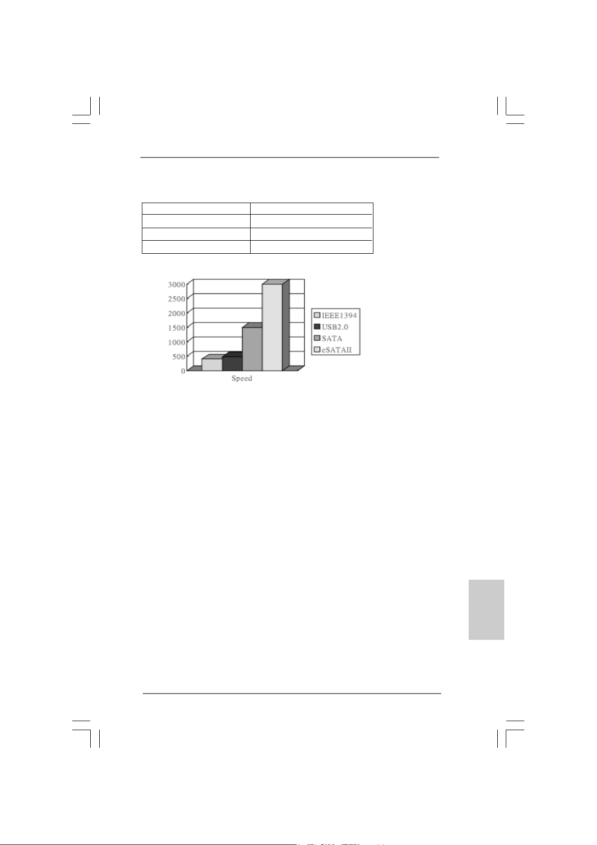
Comparison between eSATAII and other devices
IEEE 1394 400Mb/s
USB 2.0 480Mb/s
SATA 1.5Gb/s (1500Mb/s)
eSATAII/SATAII 3.0Gb/s (3000Mb/s)
ASRock 775XFire-eSATA2+ Motherboard
2929
29
2929
EnglishEnglish
EnglishEnglish
English
Page 30
2.11 SA2.11 SA
2.11 SA
2.11 SA2.11 SA
Before installing SATAII hard disk to your computer, please carefully read below
SATAII hard disk setup guide. Some default setting of SATAII hard disks may not
be at SATAII mode, which operate with the best performance. In order to enable
SATAII function, please follow the below instruction with different vendors to
correctly adjust your SATAII hard disk to SATAII mode in advance; otherwise, your
SATAII hard disk may fail to run at SA TAII mode.
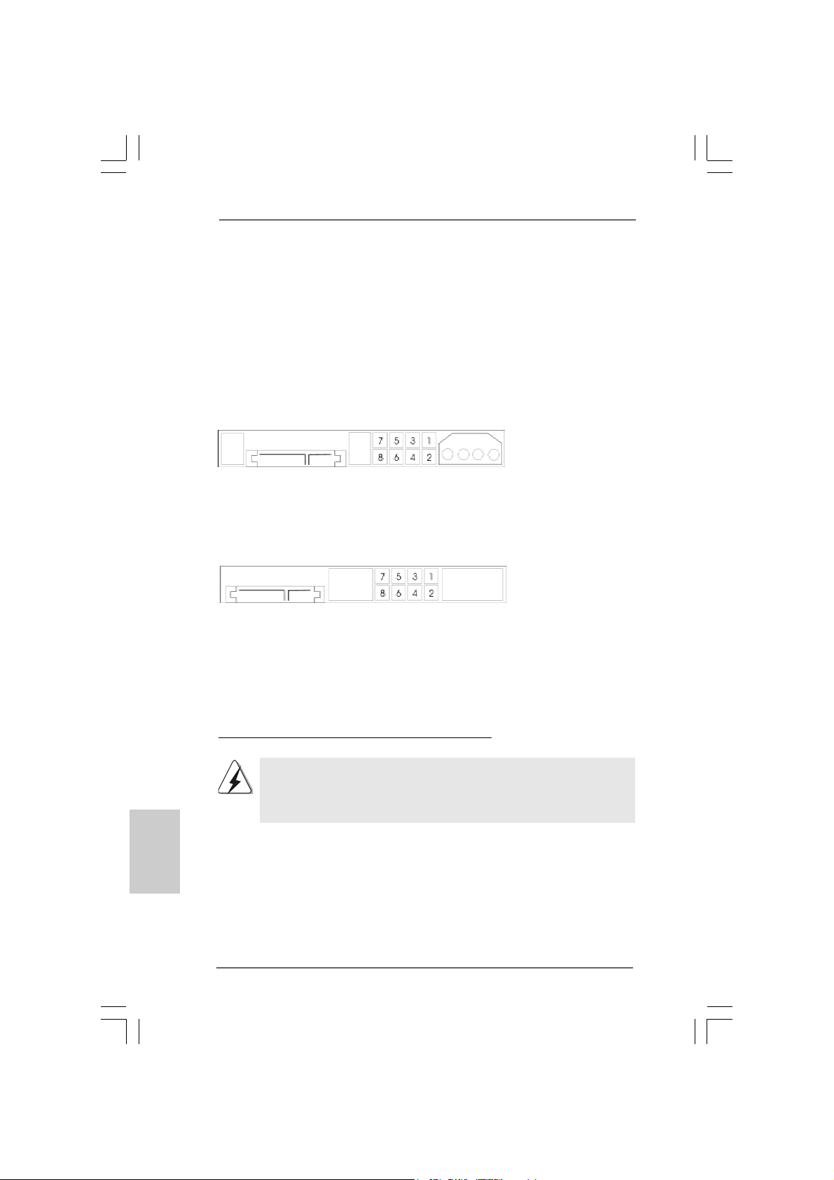
Western Digital
If pin 5 and pin 6 are shorted, SATA 1.5Gb/s will be enabled.
On the other hand, if you want to enable SATAII 3.0Gb/s, please remove the
jumpers from pin 5 and pin 6.
SAMSUNG
If pin 3 and pin 4 are shorted, SATA 1.5Gb/s will be enabled.
On the other hand, if you want to enable SATAII 3.0Gb/s, please remove the
jumpers from pin 3 and pin 4.
TT
AII Hard Disk Setup GuideAII Hard Disk Setup Guide
T
AII Hard Disk Setup Guide
TT
AII Hard Disk Setup GuideAII Hard Disk Setup Guide
English
EnglishEnglish
EnglishEnglish
3030
30
3030
HITACHI
Please use the Feature Tool, a DOS-bootable tool, for changing various ATA
features. Please visit HITACHI’s website for details:
http://www.hitachigst.com/hdd/support/download.htm
The above examples are just for your reference. For different SATAII hard
disk products of different vendors, the jumper pin setting methods may not
be the same. Please visit the vendors’ website for the updates.
ASRock 775XFire-eSATA2+ Motherboard
Page 31

2.122.12
Serial ASerial A
2.12
Serial A
2.122.12
Serial ASerial A
InstallationInstallation
Installation
InstallationInstallation
This motherboard adopts Intel® ICH7R south bridge chipset that supports Serial
ATA (SATA) / Seri al ATAII (SATAII) hard disks and RAID (RAID 0, RAID 1, RAID 10,
RAID 5, and Intel Matrix Storage) functions. You may install SATA / SATAII hard
disks on this motherboard for internal storage devices. This section will guide you
to install the SATA / SATAII hard disks.
STEP 1: Install the SATA / SATAII hard disks into the drive bays of your chassis.
STEP 2: Connect the SATA power cable to the SATA / SATAII hard disk.
STEP 3: Connect one end of the SATA data cable to the motherboard’s SATAII
connector.
STEP 4: Connect the other end of the SATA data cable to the SATA / SATAII hard
disk.
TT
A (SAA (SA
TT
A (SA
A (SAA (SA
A) / Serial AA) / Serial A
T
A) / Serial A
TT
A) / Serial AA) / Serial A
T
TT
1. If you plan to use RAID 0, RAID 1, or Intel Matrix Storage function, you
need to install at least 2 SATA / SATAII hard disks. If you plan to use
RAID 5 function, you need to install at least 3 SATA / SATAII hard disks.
If you plan to use RAID 10 function, you need to install at least 4 SATA /
SATAII hard disks. If you install 2 eSATAII devices, then only RAID 0,
RAID 1, or Intel Matrix Storage functions will be enabled.
2. It is not recommended to switch the “Configure SATA as” setting between
AHCI, RAID, and IDE mode after OS installation.
TT
AII (SAAII (SA
T
AII (SA
TT
AII (SAAII (SA
TT
AII) Hard DisksAII) Hard Disks
T
AII) Hard Disks
TT
AII) Hard DisksAII) Hard Disks
ASRock 775XFire-eSATA2+ Motherboard
3131
31
3131
EnglishEnglish
EnglishEnglish
English
Page 32

2.13 Hot Plug and Hot Swap F2.13 Hot Plug and Hot Swap F
2.13 Hot Plug and Hot Swap F
2.13 Hot Plug and Hot Swap F2.13 Hot Plug and Hot Swap F
HDDs and eSAHDDs and eSA
HDDs and eSA
HDDs and eSAHDDs and eSA
This motherboard supports Hot Plug and Hot Swap functions for SATA /
SATAII / eSATAII Devices.Intel® ICH7R south bridge chipset provides
hardware support for Advanced Host controller Interface (AHCI), a new
programming interface for SATA host controllers developed thru a joint
industry effort. AHCI also provides usability enhancements such as Hot
Plug. AHCI requires appropriate software support (e.g., an AHCI driver,
which is contained in our support CD).
NOTE
What is Hot Plug Function?
If the SATA / SATAII HDDs are NOT set for RAID configuration, it is called
“Hot Plug” for the action to insert and remove the SATA / SATAII HDDs
while the system is still power-on and in working condition.
However, please note that it cannot perform Hot Plug if the OS has been
installed into the SATA / SATAII HDD.
What is Hot Swap Function?
If SATA / SATAII HDDs are built as RAID1 then it is called “Hot Swap” for
the action to insert and remove the SATA / SATAII HDDs while the system
is still power-on and in working condition.
eSATAII is equipped with Hot Plug capability that enables you to exchange
drives easily. For example, with eSATAII interface, you may simply plug your
eSATAII devices to the eSATAII ports instead of opening your chassis to
exchange your SATAII hard disk.
TT
AII DevicesAII Devices
T
AII Devices
TT
AII DevicesAII Devices
unctions for SAunctions for SA
unctions for SA
unctions for SAunctions for SA
TT
A / SAA / SA
T
A / SA
TT
A / SAA / SA
TT
T
TT
AIIAII
AII
AIIAII
English
EnglishEnglish
EnglishEnglish
2.142.14
Driver Installation Guide Driver Installation Guide
2.14
Driver Installation Guide
2.142.14
Driver Installation Guide Driver Installation Guide
To install the drivers to your system, please insert the support CD to your optical
drive first. Then, the drivers compatible to your system can be auto-detected and
listed on the support CD driver page. Please follow the order from up to bottom
side to install those required drivers. Therefore, the drivers you install can work
properly.
3232
32
3232
ASRock 775XFire-eSATA2+ Motherboard
Page 33

2.152.15
Installing WindowsInstalling Windows
2.15
Installing Windows
2.152.15
Installing WindowsInstalling Windows
With RAID FunctionsWith RAID Functions
With RAID Functions
With RAID FunctionsWith RAID Functions
If you want to install Windows® 2000 / Windows® XP / Windows® XP 64-bit OS on
your SATA HDDs with RAID functions, please follow the below steps.
The installation procedures for Windows® VistaTM are subject to change.
STEP 1: Set up BIOS.
A. Enter BIOS SETUP UTILITY Advanced screen IDE Configuration.
B. Set “ATA/IDE Configuration” to [Enhanced], and then in the option “Configure
SATA as”, please set the option to [RAID].
STEP 2: Make a SATA Driver Diskette.
A. Insert the Support CD into your optical drive to boot your system.
B. During POST at the beginning of system boot-up, press <F11> key, and then a
window for boot devices selection appears. Please select CD-ROM as the boot
device.
C. When you see the message on the screen, “Do you want to generate Serial
ATA driver diskette [YN]?”, press <Y>.
D. Then you will see these messages,
Please insert a diskette into the floppy drive.
WARNING! Formatting the floppy diskette will
lose ALL data in it!
Start to format and copy files [YN]?
Please insert a floppy diskette into the floppy drive, and press <Y>.
E. The system will start to format the floppy diskette and copy SATA drivers into
the floppy diskette.
STEP 3: Use “RAID Installation Guide” to set RAID configuration.
Before you start to configure the RAID function, you need to check theinstallation
guide in the Support CD for proper configuration. Please refer to the document in the
Support CD, “Guide to SATA Hard Disks Installation and RAID Conf iguration”, which is
located in the folder at the following path: .. \ RAID Installation Guide
STEP 4: Install Windows® 2000 / Windows® XP / Windows® XP 64-bit OS on
your system.
After making a SATA driver diskette and using “RAID Installation Guide” to set RAID
configuration, you can start to install Windows® 2000 / Windows® XP / Windows® XP
64-bit on your system. At the beginning of Windows setup, press F6 to install a thirdparty SCSI or RAID driver. When prompted, insert a floppy disk containing the Intel
RAID driver. After reading the floppy disk, the driver will be presented. Select the
driver to install according to the mode you choose and the OS you install. You
may select: “Intel(R) 82801GR/GH SATA RAID Controller (Desktop ICH7R-Windows
XP/2000)” for Windows® XP/2000 or “Intel(R) 82801GR/GH SATA RAID Controller
(Desktop ICH7R-Windows XP64)” for Windows® XP 64-bit.
®
2000 / XP / XP 64-bit / Vista 2000 / XP / XP 64-bit / Vista
2000 / XP / XP 64-bit / Vista
2000 / XP / XP 64-bit / Vista 2000 / XP / XP 64-bit / Vista
TMTM
TM
TMTM
EnglishEnglish
EnglishEnglish
English
ASRock 775XFire-eSATA2+ Motherboard
3333
33
3333
Page 34

English
EnglishEnglish
EnglishEnglish
After the installation of Windows
to manage RAID functions, you are allowed to use both “RAID Installation Guide” and “Intel
Matrix Storage Manager Information” for RAID configuration. Please refer to the document
in the Support CD, “Guide to SATA Hard Disks Installation and RAID Configuration”, which
is located in the folder at the following path: .. \ RAID Installation Guide and the document
in the support CD, “Guide to Intel Matrix Storage Manager”, which is located in the folder at
the following path: .. \ Intel Matrix Storage Manager Information
If you want to use “Intel Matrix Storage Manager” in Windows® environment,
please install SATA drivers from the Support CD again so that “Intel Matrix
Storage Manager” will be installed to your system as well.
2.15.1 Setting Up a “RAID Ready” System2.15.1 Setting Up a “RAID Ready” System
2.15.1 Setting Up a “RAID Ready” System
2.15.1 Setting Up a “RAID Ready” System2.15.1 Setting Up a “RAID Ready” System
You can also set up a “RAID Ready” system with a single SATA hard disk. A “RAID
Ready” system can be seamlessly upgraded to RAID 0, RAID 1 or RAID 5 at a later
date by using RAID migration feature of Intel Matrix Storage. The following steps
outline how to build an Intel “RAID Ready” system.
1. Assemble the system and attach a single SATA hard drive.
2. Set up system BIOS as step 1 of page 33. When done, exit Setup.
3. Make a SATA driver diskette as step 2 of page 33. Begin Windows® setup by
booting from the installation CD.
4. At the beginning of Windows® setup, press F6 to install a third-party SCSI or
RAID driver. When prompted, insert a floppy disk containing the Intel RAID
driver. After reading the floppy disk, the driver will be presented. Select the
driver to install according to the mode you choose and the OS you install. You
may select: “Intel(R) 82801GR/GH SA TA RAID Controller (Desktop ICH7R Windows XP/2000)” for Windows® XP/2000 or “Intel(R) 82801GR/GH SATA
RAID Controller (Desktop ICH7R-Windows XP64)” for Windows® XP 64-bit.
5. Finish the Windows® installation and install all necessary drivers.
6. Install the Intel(R) Matrix Storage Manager software via the CD-ROM included
with your motherboard or after downloading it from the Internet. This will add
the Intel(R) Matrix Storage Console which can be used to manage the RAID
configuration.
7. After setting up a “RAID Ready” system as the above steps, you can follow the
procedures of the next section to migrate the system to RAID 0, RAID 1 or RAID
5.
®
2000 / Windows® XP / Windows® XP-64bit OS, if you want
3434
34
3434
ASRock 775XFire-eSATA2+ Motherboard
Page 35

2.15.2 Migrating a “RAID Ready” System to RAID 0,2.15.2 Migrating a “RAID Ready” System to RAID 0,
2.15.2 Migrating a “RAID Ready” System to RAID 0,
2.15.2 Migrating a “RAID Ready” System to RAID 0,2.15.2 Migrating a “RAID Ready” System to RAID 0,
RAID 1 or RAID 5 RAID 1 or RAID 5
RAID 1 or RAID 5
RAID 1 or RAID 5 RAID 1 or RAID 5
If you have an existing “RAID Ready” system, then you can use the following
steps to perform a migration from a single non-RAID configuration to a two drive
RAID 0, RAID 1 configuration or three drive RAID 5 configuration. To prepare for
this, you will need another SATA hard drive with a capacity equal to or greater
than that currently being used as the source hard drive.
1. Physically attach one additional SATA hard drive to the SATA port not being
used. Note the serial number of the hard drive already in the system; you will
use this to select it as the source hard drive when initiating the migration.
2. Boot Windows®, install the Intel(R) Matrix Storage Manager software, if not
already installed, using the setup package obtained from a CD-ROM or from the
Internet. This will install the necessary Intel Storage Utility and start menu links.
3. Open the Intel Storage Utility from the Start Menu and select “Create RAID
volume from Existing Hard Drive” from the Actions menu. This will activate the
Create RAID volume from Existing Hard Drive Wizard. Click through the dialogs
as prompted. It’s important to understand what will occur during the migration
process because any data on the destination hard drive will be lost.
4. Once the migration is complete, reboot the system. If you migrated to a RAID 0
volume, use Disk Management from within Windows® in order to partition and
format the empty space created when the two hard drive capacities are
combined. You may also use third-party software to extend any existing
partitions within the RAID volume.
2.162.16
Installing WindowsInstalling Windows
2.16
Installing Windows
2.162.16
Installing WindowsInstalling Windows
Without RAID FunctionsWithout RAID Functions
Without RAID Functions
Without RAID FunctionsWithout RAID Functions
If you want to install Windows® 2000 / XP / XP 64-bit on your SATA HDDs without
RAID functions, please follow the below steps.
The installation procedures for Windows® VistaTM are subject to change.
STEP 1: Set Up BIOS.
A. Enter BIOS SETUP UTILITY Advanced screen IDE Configuration.
B. Set “ATA/IDE Configuration” to [Enhanced], and then in the option “Configure
SATA as”, please set the option to [AHCI] or [IDE].
STEP 2: Make a SATA Driver Diskette. (Only when you select AHCI mode
and use SATA HDD.)
If you set “Configure SATA as” to [IDE], there is no need to make a
SATA driver diskette. If you select [AHCI] mode and install Windows® OS on
IDE drive, you do not have to make a driver diskette.
ASRock 775XFire-eSATA2+ Motherboard
®
2000 / XP / XP 64-bit / Vista 2000 / XP / XP 64-bit / Vista
2000 / XP / XP 64-bit / Vista
2000 / XP / XP 64-bit / Vista 2000 / XP / XP 64-bit / Vista
TMTM
TM
TMTM
3535
35
3535
EnglishEnglish
EnglishEnglish
English
Page 36

If you set “Configure SATA as” to [AHCI] mode, and plan to install Windows® 2000 /
XP / XP 64-bit OS on a SATA hard disk, you have to make a SATA driver diskette.
Please refer to step 2 on page 33 for details. (If you select AHCI mode and plan to
install Windows® Vista
driver diskette.) But if you choose [IDE] mode, please ignore this step.
STEP 3: Install Windows® 2000 / Windows® XP / Windows® XP 64-bit OS on
your system.
After making a SATA driver diskette, you can start to install Windows® 2000 /
XP / XP 64-bit on your system. At the beginning of Windows® setup, press F6 to
install a third-party SCSI or RAID driver. When prompted, insert a floppy disk
containing the Intel RAID driver. After reading the floppy disk, the driver will be
presented. Select the driver to install according to the mode you choose and the
OS you install. You may select: “Intel(R) 82801GR/GH SA TA AHCI Controller
(Desktop ICH7R-Windows XP/2000)” for Windows® XP/2000 or “Intel(R)
82801GR/GH SATA AHCI Controller (Desktop ICH7R-Windows XP64)” for Windows
XP 64-bit.
2.172.17
Untied Overclocking TUntied Overclocking T
2.17
Untied Overclocking T
2.172.17
Untied Overclocking TUntied Overclocking T
This motherboard supports Untied Overclocking Technology, which means during
overclocking, FSB enjoys better margin due to fixed PCI bus. You may set “CPU Host
Frequency” option of BIOS setup to [Auto], which will show you the actual CPU host
frequency in the following item. Therefore, CPU FSB is untied during overclocking,
but PCI bus is in the fixed mode so that FSB can operate under a more stable
overclocking environment.
TM
on a SATA hard disk, you don’t need to make a SATA
echnologyechnology
echnology
echnologyechnology
®
English
EnglishEnglish
EnglishEnglish
3636
36
3636
ASRock 775XFire-eSATA2+ Motherboard
Page 37

3. BIOS Information3. BIOS Information
3. BIOS Information
3. BIOS Information3. BIOS Information
The BIOS Setup Utility is stored in the BIOS FWH chip. When you start up the
computer, please press <F2> during the Power-On-Self-Test (POST) to enter the
BIOS Setup Utility; otherwise, POST continues with its test routines. If you wish to
enter the BIOS Setup Utility after POST, please resume the system by pressing <Ctl>
+ <Alt> + <Delete>, or pressing the reset button on the system chassis. For the
detailed information about the BIOS Setup Utility, please refer to the User Manual
(PDF file) contained in the Support CD.
4. Software Suppor4. Software Suppor
4. Software Suppor
4. Software Suppor4. Software Suppor
This motherboard supports various Microsoft® Windows® operating systems: 2000 /
XP / XP 64-bit / VistaTM. The Support CD that came with the motherboard contains
necessary drivers and useful utilities that will enhance motherboard features.
To begin using the Support CD, insert the CD into your CD-ROM drive. It will display
the Main Menu automatically if “AUTORUN” is enabled in your computer. If the Main
Menu does not appear automatically, locate and double-click on the file
“ASSETUP.EXE” from the “BIN” folder in the Support CD to display the menus.
“LGA 775 CPU Installation Live Demo”
This motherboard is equipped with Intel LGA 775 socket, which is a new CPU
socket interface that Intel has released. Since it has several tiny pins, whcih
are easily to be damaged by improper handling, ASRock sincerely presents
you a clear installation guide through this “LGA 775 CPU Installation Live
Demo”. We hope you may check this live demo program before you start the
installation of LGA 775 CPU in order to reduce the risks of CPU and
motherboard damages caused by any improper handling. To see this Live
Demo, you can run Microsoft® Media Player® to play the file. You may find this
Live Demo in the motherboard’s Support CD through the following path:
..\ MPEGAV \ LGA775INST.DAT
t CD informationt CD information
t CD information
t CD informationt CD information
ASRock 775XFire-eSATA2+ Motherboard
3737
37
3737
EnglishEnglish
EnglishEnglish
English
Page 38

3838
38
3838
ASRock 775XFire-eSATA2+ Motherboard
Page 39

® ® ®
®
®
®
®
ASRock 775XFire-eSATA2+ Motherboard
3939
39
3939
Page 40

4040
40
4040
®
®
ASRock 775XFire-eSATA2+ Motherboard
Page 41

®
®
®
®
®
ASRock 775XFire-eSATA2+ Motherboard
4141
41
4141
Page 42

®
®
4242
42
4242
ASRock 775XFire-eSATA2+ Motherboard
Page 43

ASRock 775XFire-eSATA2+ Motherboard
4343
43
4343
Page 44

4444
44
4444
ASRock 775XFire-eSATA2+ Motherboard
Page 45

ASRock 775XFire-eSATA2+ Motherboard
4545
45
4545
Page 46

4646
46
4646
ASRock 775XFire-eSATA2+ Motherboard
Page 47

DDRII_1 DDRII_2 DD RII_3 DDRII_4
( ) ( ) ( ) ( )
SS X SS X
DS X DS X
X SS X SS
X DS X DS
SS SS SS SS
DDRII_1 DDRII_2 DD RII_3 DDRII_4
( ) ( ) ( ) ( )
DS/SS* X X X
DS/SS X DS/SS X
X DS/SS X DS/SS
SS SS DS/SS X
SS SS SS SS
ASRock 775XFire-eSATA2+ Motherboard
4747
47
4747
Page 48

4848
48
4848
ASRock 775XFire-eSATA2+ Motherboard
Page 49

“
”
ASRock 775XFire-eSATA2+ Motherboard
4949
49
4949
Page 50

2.52.5
2.5
2.52.5
5050
50
5050
ASRock 775XFire-eSATA2+ Motherboard
Page 51

ASRock 775XFire-eSATA2+ Motherboard
5151
51
5151
Page 52

5252
52
5252
ASRock 775XFire-eSATA2+ Motherboard
Page 53

ASRock 775XFire-eSATA2+ Motherboard
5353
53
5353
Page 54

5454
54
5454
ASRock 775XFire-eSATA2+ Motherboard
Page 55

SATAII_RED
(PORT2)
SATAII_ORANGE
(PORT3)
SATAII_BLUE
(PORT0)
SATAII_BLACK
(PORT1)
eSATAII_BOTTOM
eSATAII_TOP
ASRock 775XFire-eSATA2+ Motherboard
5555
55
5555
Page 56

5656
56
5656
ASRock 775XFire-eSATA2+ Motherboard
Page 57

CD1
ASRock 775XFire-eSATA2+ Motherboard
5757
57
5757
Page 58

5858
58
5858
SLI/XFIRE_POWER1
ASRock 775XFire-eSATA2+ Motherboard
Page 59

C
B
A
ASRock 775XFire-eSATA2+ Motherboard
5959
59
5959
Page 60

6060
60
6060
ASRock 775XFire-eSATA2+ Motherboard
Page 61

ASRock 775XFire-eSATA2+ Motherboard
6161
61
6161
Page 62

6262
62
6262
ASRock 775XFire-eSATA2+ Motherboard
Page 63

IEEE 1394 400Mb/s
USB 2.0 480Mb/s
SATA 1.5Gb/s (1500Mb/s)
eSATAII/SATAII 3.0Gb/s (3000Mb/s)
ASRock 775XFire-eSATA2+ Motherboard
6363
63
6363
Page 64

6464
64
6464
®
ASRock 775XFire-eSATA2+ Motherboard
Page 65

ASRock 775XFire-eSATA2+ Motherboard
6565
65
6565
Page 66

®
® ®
®
®
6666
66
6666
® ®
®
®
® ® ®
ASRock 775XFire-eSATA2+ Motherboard
Page 67

® ® ®
®
®
®
®
ASRock 775XFire-eSATA2+ Motherboard
6767
67
6767
Page 68

®
®
6868
68
6868
ASRock 775XFire-eSATA2+ Motherboard
Page 69

®
® ®
®
®
®
®
®
®
ASRock 775XFire-eSATA2+ Motherboard
6969
69
6969
Page 70

“LGA 775 CPU Installation Live Demo”
® ®
7070
70
7070
ASRock 775XFire-eSATA2+ Motherboard
Page 71

1. Einführung1. Einführung
1. Einführung
1. Einführung1. Einführung
Wir danken Ihnen für den Kauf des ASRock 775XFire-eSATA2+ Motherboard, ein
zuverlässiges Produkt, welches unter den ständigen, strengen Qualitätskontrollen
von ASRock gefertigt wurde. Es bietet Ihnen exzellente Leistung und robuste s Design,
gemäß der Verpflichtung von ASRock zu Qualität und Halbarkeit.
Diese Schnellinstallationsanleitung führt in das Motherboard und die schrittweise
Installation ein. Details über das Motherboard finden Sie in der
Bedienungsanleitung auf der Support-CD.
Da sich Motherboard-Spezifikationen und BIOS-Software verändern können,
kann der Inhalt dieses Handbuches ebenfalls jederzeit geändert werden. Für
den Fall, dass sich Änderungen an diesem Handbuch ergeben, wird eine neue
Version auf der ASRock-Website, ohne weitere Ankündigung, verfügbar sein.
Die neuesten Grafikkarten und unterstützten CPUs sind auch auf der
ASRock-Website aufgelistet.
ASRock-Website: http://www.asrock.com
1.1 Kartoninhalt
ASRock 775XFire-eSATA2+ Motherboard
(ATX-Formfaktor: 30.5 cm x 21.8 cm; 12.0 Zoll x 8.6 Zoll)
ASRock 775XFire-eSATA2+ Schnellinstallationsanleitung
ASRock 775XFire-eSATA2+ Support-CD
(einschl. LGA 775 CPU Installation Live-Demo)
Ein 80-adriges Ultra-ATA 66/100 IDE-Flachbandkabel
Ein Flachbandkabel für ein 3,5-Zoll-Diskettenlaufwerk
Vier Serial ATA (SATA) -Datenkabel (optional)
Zwei Serial ATA (SATA) -Festplattenstromkabel (optional)
Ein HDMI_SPDIF-Kabel (Option)
Ein ASRock 8CH_eSAT AII I/O Shield
Ein USB-Halterung
ASRock 775XFire-eSATA2+ Motherboard
7171
71
7171
DeutschDeutsch
DeutschDeutsch
Deutsch
Page 72

1.21.2
SpezifikationenSpezifikationen
1.2
Spezifikationen
1.21.2
SpezifikationenSpezifikationen
Deutsch
DeutschDeutsch
DeutschDeutsch
Plattform - ATX-Formfaktor: 30.5 cm x 21.8 cm; 12.0 Zoll x 8.6 Zoll
CPU - LGA 775 für Intel® Dual Core Pentium® D- / Pentium® 4- / Celeron
D-Prozessoren, Conroe-, Presler- und Cedar M ill-Prozessoren
(im 775-poligen LGA-Gehäuse) werden unterstützt
- FSB 800/533 MHz
- Unterstützt Hyper-Threading-Technologie
(siehe VORSICHT 1)
- Unterstützt Untied-Übertaktungstechnologie
(siehe VORSICHT 2)
- Unterstützt EM64T -CPU
Chipsatz - Northbridge: Intel® 945PL-Chipsatz
- Southbridge: Intel® ICH7R
Speicher - Unterstützung von Dual-Kanal-DDRII-Speichertechnologie
(siehe VORSICHT 3)
- 4 x Steckplätze für DDRII
- Unterstützt DDRII533 (siehe VORSICHT 4)
- Max. 2GB
Hybrid Booster - Schrittloser CPU-Frequenz-Kontrolle (siehe VORSICHT 5)
- ASRock U-COP (siehe VORSICHT 6)
- Boot Failure Guard (B.F.G. – Systemstartfehlerschutz)
Erweiterungs- - Unterstützt ATI CrossFire
steckplätze - 3 x PCI -Steckplätze
- 1 x PCI Express x16-Steckplätze
- 1 x AGI Express (PCI Express x4)-Steckplätze
(siehe VORSICHT 7)
- 1 x PCI Express x1-Steckplätze
Audio - Realtek ALC888 7.1 Channel-CODEC mit High Def inition Audio
LAN - Realtek PCI LAN 8101L
- Speed: 10/100 Ethernet
- Unterstützt Wake-On-LAN
E/A-Anschlüsse ASRock 8CH_eSATAII I/O
an der - 1 x PS/2-Mausanschluss
Rückseite - 1 x PS/2-Tastaturanschluss
- 1 x Serieller port: COM 1
- 1 x Paralleler port: Unterstützung für ECP / EPP
- 2 x Standard-USB 2.0-Anschlüsse
- 2 x eSATAII Ports
- 1 x RJ-45 Port
TM
®
7272
72
7272
ASRock 775XFire-eSATA2+ Motherboard
Page 73

- HD Audiobuchse: Lautsprecher seitlich / Lautsprecher hinten
/ Mitte/Bass / Audioeingang/ Lautsprecher vorne / Mikrofon
(siehe VORSICHT 8)
Anschlüsse - 4 x Serial ATAII 3,0 GB/s-Anschlüsse, unterstützen RAID-
(RAID 0, RAID 1, RAID 10, RAID 5 und Intel Matrix Storage),
NCQ, AHCI und “Hot Plug” Funktionen (siehe VORSICHT 9)
- 2 x eSATAII 3.0 GB/s-Anschlüsse (mit 2 SATAII-An schlüssen
geteilt), unterstützt „Hot Plug“-Funktion (siehe VORSICHT 10)
- 1 x ATA100 IDE-Anschlüsse (Unterstützt bis 2 IDE-Geräte)
- 1 x FDD-Anschlüsse
- 1 x Infrarot-Modul-Header
- 1 x Game-Anschluss
- 1 x HDMI_SPDIF-Anschluss
- CPU/Gehäuse-Lüfteranschluss
- 20-pin ATX-Netz-Header
- 4-pin anschluss für 12V-ATX-Netzteil
- SLI/XFIRE-Netz-Header
- Interne Audio-Anschlüsse
- Anschluss für Audio auf der Gehäusevorderseite
- 3 x USB 2.0-Anschlüsse (Unterstützung 6
zusätzlicher USB 2.0-Anschlüsse) (siehe VORSICHT 11)
BIOS - 4Mb AMI BIOS
- AMI legal BIOS mit Unterstützung für “Plug and Play”
- ACPI 1.1-Weckfunktionen
- JumperFree-Modus
- SMBIOS 2.3.1
Support-CD - Treiber, Dienstprogramme, Antivirussoftware
(Probeversion)
Hardware Monitor - Überwachung der CPU-Temperatur
- Motherboardtemperaturerkennung
- Drehzahlmessung für CPU-Lüfter
- Drehzahlmessung für Gehäuselüfter
- CPU-Lüftergeräuschdämpfung
- Spannungsüberwachung: +12V, +5V, +3.3V, Vcore
Betriebssysteme - Unterstützt Microsoft® Windows® 2000 / XP / XP 64-Bit /
VistaTM (siehe VORSICHT 12)
Zertifizierungen - FCC, CE, WHQL
DeutschDeutsch
DeutschDeutsch
Deutsch
ASRock 775XFire-eSATA2+ Motherboard
7373
73
7373
Page 74

Deutsch
DeutschDeutsch
DeutschDeutsch
7474
74
7474
VORSICHT!
1. Die Einstellung der “Hyper-Threading Technology”, finden Sie auf Seite
44 des auf der Support-CD enthaltenen Benutzerhandbuches
beschrieben.
2. Dieses Motherboard unterstützt die Untied-Übertaktungstechnologie.
Unter “Entkoppelte Übertaktungstechnologie” auf Seite 103 finden Sie
detaillierte Informationen.
3. Dieses Motherboard unterstützt Dual-Kanal-Speichertechnologie. Vor
Implementierung der Dual-Kanal-Speichertechnologie müssen Sie die
Installationsanleitung für die Speichermodule auf Seite 80 zwecks richtiger
Installation gelesen haben.
4. Dieses Motherboard unterstützt zwei Doppelseitige DIMMs oder vier
Einseitige DIMMs. Details zu weiteren Einschränkungen finden Sie unter
„Installation von Speichermodulen (DIMMs)“ auf Seite 80.
5. Obwohl dieses Motherboard stufenlose Steuerung bietet, wird Overclocking nicht empfohlen. Frequenzen, die über den für den jeweiligen
Prozessor vorgesehenen liegen, können das System instabil werden
lassen oder die CPU beschädigen.
6. Wird eine Überhitzung der CPU registriert, führt das System einen
automatischen Shutdown durch. Bevor Sie das System neu starten, prüfen
Sie bitte, ob der CPU-Lüfter am Motherboard richtig funktioniert, und
stecken Sie bitte den Stromkabelstecker aus und dann wieder ein. Um die
Wärmeableitung zu verbessern, bitte nicht vergessen, etwa s Wärmeleitpa ste
zwischen CPU und Kühlkörper zu sprühen.
7. Informationen zu kompatiblen PCI Express-VGA-Karten finden Sie unter
„Unterstützte PCI Express-VGA-Karten für AGI Express-Steckplatz (PCI
Express x4)“ auf Seite 9. Hinweise zur richtigen Installation von PCI
Express-VGA-Karten finden Sie in der Installationsanleitung auf Seite
82.
8. For microphone input, this motherboard supports both stereo and mono
modes. For audio output, this motherboard supports 2-channel, 4-channel,
6-channel, and 8-channel modes. Please check the table on page 3 for
proper connection.
9. Bevor Sie eine SATA II Festplatte mit dem SATA II Anschluss verbinden,
lesen Sie bitte die “Anleitung zur SATA II Festplatteneinrichtung“ auf
Seite 97, um Ihre SATA II Festplatte in den SATA II Modus umzuschalten.
Übrigens können Sie eine SATA II-Festplatte auch als SATA Festplatte
einsetzen (von SATA II 3 GB/s auf SATA 1,5 GB/s herabstufen) und mit
dem SATA II Anschluss verbinden. SATA-Festplatten können Sie auch
direkt mit dem SATA II-Anschluss verbinden.
10. Dieses Motherboard unterstützt die eSATAII-Schnittstelle, externe
SATAII-Spezifikation. Bitte lesen Sie den Abschnitt „Vorstellung der
eSATAII-Schnittstelle“ auf Seite 95. Dort finden Sie detaillierte
Informationen über eSATAII und zur eSATAII-Installation. (Die Port
Multiplier-Technologie wird von der eSATAII-Schnittstelle dieses
Motherboards nicht unterstützt.)
ASRock 775XFire-eSATA2+ Motherboard
Page 75

11. Das Power Management für USB 2.0 arbeitet unter Microsoft® Windows
VistaTM / XP 64-Bit / XP SP1 oder SP2/2000 SP4 einwandfrei.
12. Der Treiber für Microsoft® Windows® VistaTM ist noch nicht einsatzbereit.
Sie können ihn bald von unserer Internetseite abrufen. Auf unserer
Internetseite finden Sie Angaben zum Microsoft® Windows® Vista
Treiber sowie weitere Informationen.
ASRock-Internetseite: http://www.asrock.com
TM
®
1.31.3
Minimale Hardwarevorausetzungen für WindowsMinimale Hardwarevorausetzungen für Windows
1.3
Minimale Hardwarevorausetzungen für Windows
1.31.3
Minimale Hardwarevorausetzungen für WindowsMinimale Hardwarevorausetzungen für Windows
TMTM
TM
TMTM
VistaVista
Vista
VistaVista
Systemintegratoren und Anwender unseres Motherboards, die ihre
Rechner auf die Vergabe des Windows® VistaTM Premium und Basic Logos vorbereiten möchten, finden die minimalen
Hardwarevoraussetzungen in der folgenden Tabelle. Bitte nutzen Sie die
von uns empfohlenen Prozessoren, Speicherbausteine und VGA Komponenten.
CPU Celeron D 326
Speicher 512 MB, Single Channel
VGA DX9.0 mit WDDM-Treiber
Premium und Basic Logo Premium und Basic Logo
Premium und Basic Logo
Premium und Basic Logo Premium und Basic Logo
mit 128 Bit-VGA-Speicher (Pre mium)
mit 64 Bit-VGA-Speicher (Basic)
®
ASRock 775XFire-eSATA2+ Motherboard
7575
75
7575
DeutschDeutsch
DeutschDeutsch
Deutsch
Page 76

2. Installation2. Installation
2. Installation
2. Installation2. Installation
Sicherheitshinweise vor der MontageSicherheitshinweise vor der Montage
Sicherheitshinweise vor der Montage
Sicherheitshinweise vor der MontageSicherheitshinweise vor der Montage
Bitte nehmen Sie die folgende Sicherheitshinweise zur Kenntnis, bevor Sie das
Motherboard einbauen oder Veränderungen an den Einstellungen vornehmen.
1. Trennen Sie das System vom Stromnetz, bevor Sie eine ystemkomponente
berühren, da es sonst zu schweren Schäden am Motherboard oder den
sonstigen internen, bzw. externen omponenten kommen kann.
2. Um Schäden aufgrund von statischer Elektrizität zu vermeiden, das
Motherboard NIEMALS auf einen Teppich o.ä.legen. Denken Sie außerem
daran, immer ein geerdetes Armband zu tragen oder ein geerdetes Objekt
aus Metall zu berühren, bevor Sie mit Systemkomponenten hantieren.
3. Halten Sie Komponenten immer an den Rändern und vermeiden Sie
Berührungen mit den ICs.
4. Wenn Sie Komponenten ausbauen, legen Sie sie immer auf eine
antistatische Unterlage, oder zurück in die Tüte, mit der die Komponente
geliefert wurde.
5. Wenn Sie das Motherboard mit den Schrauben an dem Computergehäuse
befestigen, überziehen Sie bitte die Schrauben nicht! Das Motherboard kann
sonst beschädigt werden.
2.1 CPU Installation2.1 CPU Installation
2.1 CPU Installation
2.1 CPU Installation2.1 CPU Installation
Für die Installation des Intel 775-Pin CPU
führen Sie bitte die folgenden Schritte durch.
(Ladeplatte)
(Kontaktreihe)
(Sockel)
Deutsch
DeutschDeutsch
DeutschDeutsch
7676
76
7676
775-Pin Sockel Übersicht
Bevor Sie die 775-Pin CPU in den Sockel sitzen, prüfen Sie bitte,
ob die CPU-Oberfläche sauber ist und keine der Kontakte verbogen
sind. Setzen Sie die CPU nicht mit Gewalt in den Sockel, dies kann
die CPU schwer beschädigen.
ASRock 775XFire-eSATA2+ Motherboard
Page 77

Schritt 1. Öffnen Sie den Sockel:
Schritt 1-1. Öffnen Sie den Hebel, indem
Sie ihn nach unten drücken und
aushaken.
Schritt 1-2. Drehen Sie den Ladehebel, bis
er in geöffneter Position steht,
ca. 135 Grad.
Schritt 1-3. Drehen Sie die Ladeplatte, bis
sie in geöffneter Position steht,
ca. 100 Grad.
Schritt 2. 775-Pin CPU einstecken:
Schritt 2-1. Halten Sie die CPU an den mit
schwarzen Linien
gekennzeichneten Seiten.
Schritt 2-2. Halten Sie das Teil mit dem IHS
(Integrated Heat Sink –
integrierter Kühlkörper) nach
oben. Suchen Sie Pin 1 und die
zwei
Orientierungseinkerbungen.
Pin1
Orientierungskerbe
Ausrichtungsmarkierung
Orientierungskerbe
Pin1
Schwarze Linie
775-Pin Sockel
Schwarze Linie
Ausrichtungsmarkierung
775-Pin CPU
Um die CPU ordnungsgemäß einsetzen zu können, richten Sie die
zwei Orientierungskerben der CPU mit den beiden Markierungen des
Sockels aus.
Schritt 2-3. Drücken Sie die CPU vorsichtig
in vertikaler Richtung in den
Sockel.
ASRock 775XFire-eSATA2+ Motherboard
7777
77
7777
DeutschDeutsch
DeutschDeutsch
Deutsch
Page 78

Schritt 2-4. Prüfen Sie, dass die CPU
ordnungsgemäß im Sockel sitzt
und die Orientierungskerben
einwandfrei in den
entsprechenden Auskerbungen
sitzen.
Schritt 3. PnP-Kappe entfernen (Pick and Place-Kappe):
Halten Sie den Rand der Ladeplatte mit
Zeigefinger und Daumen Ihrer linken Hand,
halten Sie die PnP-Kappe mit dem Daumen
der rechten Hand und ziehen Sie die Kappe
vom Sockel während Sie auf die Mitte der
Kappe drücken, um ein Entfernen zu
erleichtern.
1. Verwenden Sie beim Entfernen die Kappenlasche und vermeiden
Sie ein Abreißen der PnP-Kappe.
2. Diese Kappe muss angebracht werden, falls Sie das Motherboard
zur Reparatur bringen.
Schritt 4. Sockel schließen:
Schritt 4-1. Drehen Sie die Ladeplatte auf
den Kühlkörper (IHS).
Schritt 4-2. Drücken Sie leicht auf die
Ladeplatte und schließen Sie
den Ladehebel.
Schritt 4-3. Sichern Sie Ladehebel und
Ladeplatte mithilfe des
Hebelverschlusses.
Deutsch
DeutschDeutsch
DeutschDeutsch
7878
78
7878
ASRock 775XFire-eSATA2+ Motherboard
Page 79

2.22.2
Installation des CPU-Lüfters und KühlkörpersInstallation des CPU-Lüfters und Kühlkörpers
2.2
Installation des CPU-Lüfters und Kühlkörpers
2.22.2
Installation des CPU-Lüfters und KühlkörpersInstallation des CPU-Lüfters und Kühlkörpers
Für Installationshinweise, siehe Betriebsanleitung Ihres CPU-Lüfters und
Kühlkörpers.
Unten stehend ein Beispiel zur Installation eines Kühlkörpers für den 775-Pin CPU.
Schritt 1. Geben Sie Wärmeleitmaterial auf die Mitte
des IHS, auf die Sockeloberfläche.
Schritt 2. Setzen Sie den Kühlkörper auf den Sockel.
Prüfen Sie, dass die Lüfterkabel auf der
Seite am nächsten zum CPU-LüfterAnschluss des Motherboards verlaufen
(CPU_FAN1, siehe Seite 2, Nr. 6).
Schritt 3. Richten Sie Verbindungselemente und
Löcher im Motherboard aus.
Schritt 4. Drehen Sie die Verbindungselemente im
Uhrzeigersinn und drücken Sie mit dem
Daumen auf die Kappen der Elemente zum
Feststellen. Wiederholen Sie dies mit den
anderen Verbindungselementen.
Wenn Sie die Verbindungselemente nur drücken, ohne sie im
Uhrzeigersinn zu drehen, wird der Kühlkörper nicht ordnungsgemäß
am Motherboard befestigt.
(Tragen Sie Wärmeleitmaterial auf. )
(Lüfterkabel auf der Seite am nächsten
zum Anschluss des Motherboards)
(Schlitze der Verbindungselemente
nach außen)
(Nach unten drücken (4 Stellen))
Schritt 5. Schließen Sie den Lüfter an den CPU-
Lüfteranschluss des Motherboards.
Schritt 6. Befestigen Sie überschüssiges Kabel mit
Band, um eine Störung des Lüfters oder
Kontakt mit anderen Teilen zu vermeiden.
ASRock 775XFire-eSATA2+ Motherboard
7979
79
7979
DeutschDeutsch
DeutschDeutsch
Deutsch
Page 80

2.3 Installation der Speichermodule (DIMM)2.3 Installation der Speichermodule (DIMM)
2.3 Installation der Speichermodule (DIMM)
2.3 Installation der Speichermodule (DIMM)2.3 Installation der Speichermodule (DIMM)
Die Motherboards 775XFire-eSATA2+ bieten vier 240-pol. DDRII (Double Data
Rate II) DIMM-Steckplätze und unterstützen die Dual-Kanal-Speichertechnologie.
Für die Dual-Kanalkonfiguration dürfen Sie nur identische (gleiche Marke,
Geschwindigkeit, Größe und gle icher Chiptyp) DDRII DIMM-Paare in den
Steckplätzen gleicher Farbe installieren. Mit anderen Worten, sie müssen ein
identisches DDR DIMM-Paar im Dual-Kanal A (DDRII_1 und DDRII_3; gelbe
Steckplätze, siehe Seite 2 Nr. 7) oder ein identisches DDRII DIMM-Paar im DualKanal B (DDRII_2 und DDRII_4; orange Steckplätze, siehe Seite 2 Nr. 8) installieren,
damit die Dual-Kanal-Speichertechnologie aktiviert werden kann. Auf diesem
Motherboard können Sie auch vier DDRII DIMMs für eine Dual-Ka n a lkonf iguration
installieren. Auf diesem Motherboard können Sie auch vier DDRII DIMM-Module für
eine Dual-Kanalkonfiguration installieren, wobei Sie bitte in allen vier Steckplätzen
identische DDRII DIMM-Module installieren. Beziehen Sie sich dabei auf die
nachstehende Konfigurationstabelle für Dual-Kanalspeicher.
Dual-Kanal-Speicherkonfigurationen
(DS: Doppelseitig, SS: Einseitig)
DDRII_1 DDRII_2 DDRII_3 DDRII_4
(gelbe Steckplätze) (orange Steckplätze) (gelbe Steckplätze) (orange Steckplätze)
2 Speichermodule SS X SS X
2 Speichermodule DS X DS X
2 Speichermodule X SS X SS
2 Speichermodule X DS X DS
4 Speichermodule SS SS SS SS
Deutsch
DeutschDeutsch
DeutschDeutsch
8080
80
8080
1. Wenn Sie zwe i Speichermodule installieren möchten, verwenden Sie
dazu für optimale Kompatibilität und Stabilität Steckplätze gleicher
Farbe. Installieren Sie die beiden Speichermodule also entweder in
den gelbe Steckplätzen (DDRII_1 und DDRII_3) oder den orange
Steckplätzen (DDRII_2 und DDRII_4).
2. Wenn nur ein Speichermodul oder drei Speichermodule in den DDRII
DIMM-Steckplätzen auf diesem Motherboard installiert sind, kann es
die Dual-Kanal-Speichertechnologie nicht aktivieren.
3. Ist ein Speichermodulpaar NICHT im gleichen “Dual-Kanal” installiert,
z.B. ein Speichermodulpaar wird in DDRII_1 und DDRII_2 installiert,
kann es die Dual-Kanal-Speichertechnologie nicht aktivieren.
4. Es ist nicht zulässig, DDR in einen DDRII Steckplatz zu installieren;
andernfalls könnten Motherboard und DIMMs beschädigt werden.
ASRock 775XFire-eSATA2+ Motherboard
Page 81

Empfohlene Speicherkonfigurationen
(DS: Doppelseitig, SS: Einseitig)
DDRII_1 DDRII_2 DDRII_3 DD RII_4
(gelbe Steckplätze) (orange Steckplätze) (gelbe Steckplätze) (orange Steckplätze)
1 Speichermodule DS/SS* X X X
2 Speichermodule DS/SS X DS/SS X
2 Speichermodule X DS/SS X DS/SS
3 Speichermodule SS SS DS/SS X
4 Speichermodule SS SS SS SS
* Wenn Sie nur ein einziges Speichermodul installieren, können Sie dieses in einen der vier
Steckplätze einsetzen.
Diese beiden TRANSCEND-Speichermodule werden nur unter den folgenden
Bedingungen unterstützt:
DRAM- GRÖSSE TYP ZELLENAN ZELLENNUMMER EINSEITIG
ANBIETER (MB) -BIETER / DOPPEL
SEITIG
TRANSCEND 256 DD RII533 SAMSUNG K4T56083QF-ZCD5 EINSEITIG
TRANSCEND 512 DDRII533 INFINEON HYB18T512800AF37 EINSEITIG
1. Wenn Sie eines der oben genannten Speichermodule installieren möchten,
können Sie einen beliebigen DDRII-Steckplatz des Motherboards benutzen.
2. Falls Sie zwei der oben genannten Speichermodule installieren möchten, sollten
Sie diese jeweils entweder in den gelben Steckplätzen (DDRII_1 und DDRII_3)
oder in den orangefarbenen Steckplätzen (DDRII_2 und DDRII_4) installieren.
3. Drei oder vier der oben genannten Speichermodule werden nicht von diesem
Motherboard unterstützt.
Einsetzen eines DIMM-Moduls
Achten Sie darauf, das Netzteil abzustecken, bevor Sie DIMMs oder
Systemkomponenten hinzufügen oder entfernen.
Schritt 1: Öffnen Sie einen DIMM-Slot, indem Sie die seitlichen Clips nach außen
drücken.
Schritt 2: Richten Sie das DIMM-Modul so über dem Slot aus, dass das Modul mit
der Kerbe in den Slot passt.
ASRock 775XFire-eSATA2+ Motherboard
8181
81
8181
DeutschDeutsch
DeutschDeutsch
Deutsch
Page 82

Deutsch
DeutschDeutsch
DeutschDeutsch
Die DIMM-Module passen nur richtig herum eingelegt in die
Steckplätze. Falls Sie versuchen, die DIMM-Module mit Gewalt falsch
herum in die Steckplätze zu zwingen, führt dies zu dauerhaften
Schäden am Mainboard und am DIMM-Modul.
Schritt 3: Drücken Sie die DIMM-Module fest in die Steckplätze, so dass die
Halteklammern an beiden Enden des Moduls einschnappen und das
DIMM-Modul fest an Ort und Stelle sitzt.
2.4 Erweiterungssteckplätze: (PCI- , PCI Express-und AGI2.4 Erweiterungssteckplätze: (PCI- , PCI Express-und AGI
2.4 Erweiterungssteckplätze: (PCI- , PCI Express-und AGI
2.4 Erweiterungssteckplätze: (PCI- , PCI Express-und AGI2.4 Erweiterungssteckplätze: (PCI- , PCI Express-und AGI
Express-Slots): Express-Slots):
Express-Slots):
Express-Slots): Express-Slots):
Es stehen 3 PCI- , 2 PCI Express - und 1 AGI Express -Slot (PCI Express x4) auf
dem 775XFire-eSATA2+ Motherboard zur Verfügung.
PCI-Slots: PCI-Slots werden zur Installation von Erweiterungskarten mit dem 32bit
PCI-Interface genutzt.
PCI Express-Slots: PCIE1 (PCIE x16-Steckplatz) wird für PCI Express-
Grafikkarten mit x16-Busbreite verwendet. PCIE2 (PCIE x1 Steckplatz) wird für PCI Express-Karten wie Gigabit LAN Karten, SATA 2-Karten, usw. eingesetzt.
AGI Express-Slot: AGI Express Steckplatz (PCI Express x4) ist für den
Anschluss von PCI Express-Erweiterungskarten. Für weitere
Informationen bezüglich kompatibler PCI Express VGA-Karten,
siehe „Liste unterstützter PCI Express VGA-Karten für AGI
Express Steckplatz (PCI Express x4)” auf Seite 9.
Einbau einer ErweiterungskarteEinbau einer Erweiterungskarte
Einbau einer Erweiterungskarte
Einbau einer ErweiterungskarteEinbau einer Erweiterungskarte
Schritt 1: Bevor Sie die Erweiterungskarte installieren, vergewissern Sie sich,
dass das Netzteil ausgeschaltet und das Netzkabel abgezogen ist.
Bitte lesen Sie die Dokumentation zur Erweiterungskarte und nehmen
Sie nötige Hardware-Einstellungen für die Karte vor, ehe Sie mit der
Installation beginnen.
Schritt 2: Entfernen Sie das Abdeckungsblech (Slotblende) von dem
Gehäuseschacht (Slot) , den Sie nutzen möchten und behalten die
Schraube für den Einbau der Karte.
Schritt 3: Richten Sie die Karte über dem Slot aus und drücken Sie sie ohne
Gewalt hinein, bis sie den Steckplatz korrekt ausfüllt.
Schritt 4: Befestigen Sie die Karte mit der Schraube aus Schritt 2.
8282
82
8282
ASRock 775XFire-eSATA2+ Motherboard
Page 83

TMTM
TM
2.52.5
CrossFireCrossFire
2.5
CrossFire
2.52.5
CrossFireCrossFire
Dieses Motherboard unterstützt die CrossFireTM-Funktion. Die CrossFireTMTechnologie bietet die nützlichsten Vorteile beim Zusammenschließen mehrerer
leistungsstarken GPUs (Graphics Processing Units) in einem PC an. Durch das
Kombinieren verschiedener Betriebsmodi, das intelligente Software-Design sowie
einen innovativen Zusammenschaltmechanismus ermöglicht CrossFireTM das
maximal mögliche Leistungsniveau und die maximale Bildqualität in allen 3DApplikationen. Zur Zeit wird die CrossFireTM-Funktion nur von Windows XP mit
Service Pack 2 unterstützt. Die anderen Betriebssysteme werden in der Zukunft
möglicherweise auch diese Funktion unterstützen.
Karten für AGI Express-Steckplatz Karten für PCI Express-Steckplatz
Radeon X1800-Serie Radeon X1800 CrossFire TM Edition
Radeon X1600-Serie Radeon X1600-Serie
Radeon X1300-Serie Radeon X1300-Serie
Radeon X850-Serie Radeon X850 CrossFire TM Edition
TMTM
Bedienungsanleitung Bedienungsanleitung
Bedienungsanleitung
Bedienungsanleitung Bedienungsanleitung
Welche Grafikkarten funktionieren mit CrossFireTM?
Ein rundum CrossFire TM-kompatibles System erfordert ein CrossFire TM ReadyMotherboard, eine CrossFire TM Edition-Grafikkarte und eine kompatible
Radeon-Standardgrafikkarte (CrossFire TM Ready) derselben Serie, oder zwei
CrossFire TM Ready-Karte, sofern diese durch Software aktiviert werden. Dies
gilt für ATI-Karten und Karten von ATI-Partnern.
Den VDen V
Den V
Den VDen V
1. Wenn IHr System nicht richtig konfiguriert ist, konnen Sie die
Leistungsvorteile von CrossFire
Komponenten, eine CrossFireTM Ready Grafikkarte, ein CrossFireTM Ready
Motherboard und eine CrossFireTM Edition Co-Prozessor-Grafikkarte, müssen
richtig installiert werden, um Nutzen aus der CrossFireTM Multi-GPU-Plattform
zu ziehen.
2. Wenn eine 12-Pipe CrossFireTM Edition Karte mit einer 16-Pipe-Karte
zusammen verwendet wird, arbeiten die beiden Karten nur mit 12 Pipelines
im CrossFireTM-Modus.
oror
teil der CrossFteil der CrossF
or
teil der CrossF
oror
teil der CrossFteil der CrossF
ATI bietet derzeit Grafikkarten der Serie Radeon X850XT, X1800XT, X1300 und
X1600 CrossFireTM an, bei denen die CrossFireTM-Funktionen jeweils
unterschiedlich aktiviert werden. Bei den folgenden Schritten benutzen wir eine
Radeon X850XT zur Verdeutlichung. Bei anderen CrossFireTM-Karten aus der
aktuellen oder zukünftigen Produktpalette von ATI lesen Sie zur Installation bitte
in den jeweiligen Bedienungsanleitungen zur Grafikkarte nach.
ASRock 775XFire-eSATA2+ Motherboard
ireire
ire
ireire
TM
nicht erleben. Alle drei CrossFire
TMTM
TM
TMTM
genießen genießen
genießen
genießen genießen
TM
DeutschDeutsch
DeutschDeutsch
Deutsch
8383
83
8383
Page 84

Schritt 1. Nehmen Sie die Stromversorgungsverbindung vor. Verbinden Sie
bitte einen Festplattenstromsteckverbinder mit dem SLI/XFIRE PowerAnschluss.
Wir empfehlen Ihnen ein Netzteil mit 500 Watt oder noch
höherer Leistung zu verwenden, um die CrossFireTMFunktion zu nutzen.
Schritt 2. Stecken Sie die normale Radeon (CrossFireTM Ready) Grafikkarte in
den AGI Express-Steckplatz (PCI Express x 4) ein. Für Hinweise zur
Installation sehen Sie bitte im Abschnitt “Erweiterungssteckplätze”
nach.
Normale Radeon
(CrossFireTM Ready)
Grafikkarte
Schritt 3. Stecken Sie die Radeon CrossFireTM Edition Grafikkarte in den PCI
Express x 16-Steckplatz ein. Für Hinweise zur Installation sehen Sie
bitte im Abschnitt “Erweiterungssteckplätze” nach.
Deutsch
DeutschDeutsch
DeutschDeutsch
8484
84
8484
Radeon CrossFire
Edition Grafikkarte
Normale Radeon
(CrossFireTM Ready)
Grafikkarte
Sie können entweder zwei CrossFireTM Edition Grafikkarten in die beiden
Steckplätze einstecken oder eine CrossFireTM Edition Grafikkarte und eine
kompatible normale Radeon (CrossFireTM Ready) Grafikkarte von der selben
Serie verwenden.
TM
Schritt 4. Verbinden Sie das DVI-DMS-Kabel mit den zwei installierten
Grafikkarten und dem Anschluss am Monitor. (Wenn Sie zwei
Radeon-Standardgrafikkarten (CrossFire TM Ready) in diesem
Motherboard installieren, überspringen Sie bitte diesen Schritt.)
DVI-DMS-Kabel
DMS-Anschluss
DVI-Anschluss
ASRock 775XFire-eSATA2+ Motherboard
Page 85

Normale Radeon (CrossFireTM Ready)
Grafikkarte
DVI-Anschluss
Verbinden Sie das DVI-DMS
-Kabel mit dem DVIAnschluss an der kompatiblen
normalen Radeon (CrossFire
Ready) Grafikkarte.
Radeon CrossFire
Edition Grafikkarte
Wenn Sie zwei CrossFire
ein Ende des DVI-DMS-Kabels mit dem Anschluss am Monitor, ein anderes
Ende mit dem DMS-Anschluss an der CrossFireTM Edition Grafikkarte, die im
PCIE1-Steckplatz (PCI Express x 16) sitzt, und das andere Ende mit dem DVIAnschluss an der CrossFireTM Edition Grafikkarte, die im AGI ExpressSteckplatz (PCI Express x 4) sitzt. Wenn Sie eine CrossFireTM Edition
Grafikkarte und eine kompatible normale Radeon (CrossFireTM Ready)
Grafikkarte installieren, verbinden Sie bitte ein Ende des DVI-DMS-Kabels mit
dem DVI-Anschluss am Monitor, ein anderes Ende mit dem DMS-Anschluss an
der CrossFireTM Edition Grafikkarte und das andere Ende mit dem Anschluss an
der Radeon (CrossFireTM Ready) Grafikkarte.
Es gibt zwei DVI-Anschlüsse an der normalen
Radeon (CrossFireTM Ready) Grafikkarte.
TM
TM
Bitte verbinden Sie das DVI-DMS-Kabel mit
dem richtigen DVI-Anschluss. Andernfalls
kann die Grafikkarte nicht funktionieren.
DMSAnschluss
Verbinden Sie da s DVI-DMSKabel mit dem DMS-Anschluss
an der CrossFire
Grafikkarte.
TM
Edition
TM
Edition Grafikkarten installieren, verbinden Sie bitte
Verbinden Sie das DVI-DMSKabel mit dem Anschluss
am Monitor.
Schritt 5. Schalten Sie den Computer ein und fahren das Betriebssystem hoch.
Schritt 6. Entfernen Sie jeden früher installierten ATI-VGA-Treiber von Ihrem
System.
Hierzu ist der Catalyst Uninstaller hilfreich. Wir empfehlen Ihnen, dieses
Dienstprogramm zu verwenden, um alle früher installierten Catalyst-Treiber zu
deinstallieren. Bitte besuchen Sie die folgende Website, um das Dienstprogramm
herunterzuladen: http://support.ati.com/ics/support/DLRedirect.asp?
fileIDExt=050553d40196ef109fff37cbb40aaf28&accountID=737&deptID=894
ASRock 775XFire-eSATA2+ Motherboard
8585
85
8585
DeutschDeutsch
DeutschDeutsch
Deutsch
Page 86

Schritt 7. Installieren Sie die notwendigen Treiber für Ihr System. Bitte
besuchen Sie die folgenden Websites für die Treiber, die ATI
empfiehlt:
A. ATI empfiehlt die Installation des windows XP service Pack 2 order
dessen Nachfolger (Wenn Windows XP Service Pack 2 oder
dessen Nachfolger bereits in lhrem System installiert ist, dann
mussen Sie es nicht emeut downloaden):
http://www.microsoft.com/windowsxp/sp2/default.mspx
B. Vor dem Downloaden und Installieren des CATALYST Control
Center muss Microsoft .NET Framework installiert werden:
http://www.microsoft.com/downloads/details.aspx?
FamilyId=262D25E3-F589-4842-8157-
034D1E7CF3A3&displaylang=en
Schritt 8. Starten Sie den Computer neu.
Schritt 9. Installieren Sie die VGA-Kartentreiber und starten dann den Computer
neu. “ATI Catalyst Control Center” wird auf Ihrem Desktop angezeigt
(der ATI Catalyst-Treiber sollte die Version 5.10 oder eine noch
neuere Version sein).
“ATI Catalyst Control
Center” wird auf Ihrem
Desktop angezeigt.
Deutsch
DeutschDeutsch
DeutschDeutsch
8686
86
8686
Schritt 10. Klicken Sie doppelt auf “ATI Catalyst Control Center”. Klicken Sie auf
“View” (Ansicht) und wählen dann “Advanced View” (Erweiterte
Ansicht). Klicken Sie auf “CrossFireTM” und haken dann die Option
“Enable CrossFireTM” (CrossFireTM aktivieren) an.
ASRock 775XFire-eSATA2+ Motherboard
Page 87

View
(Ansicht)
CrossFire
Schritt 11. Jetzt können Sie den Nutzen aus der CrossFireTM-Funktion ziehen.
* CrossFireTM ist ein eingetragenes Warenzeichen der ATI Technologies Inc. und wird nur zur
Identifizierung oder Erläuterung und zu Gunsten des Inhabers, ohne
Rechtverletzungsabsicht, verwendet.
2.6 “Surround Display”2.6 “Surround Display”
2.6 “Surround Display”
2.6 “Surround Display”2.6 “Surround Display”
Dieses Motherboard unterstützt Surround Display-Aufrüstung. Mit zusätzlichen
PCI Express-VGA-Karte können Sie die Vorteile der Surround Display-Funktion
problemlos genießen. Für detaillierte Informationen, siehe folgendes Dokument auf
beiliegender Support-CD: ..\ Surround Display Information
TM
Enable CrossFire
(CrossFire
Befolgen Sie bitte auch die obigen Schritte, wenn Sie statt zwei Radeon
CrossFireTM Edition Grafikkarten eine Radeon CrossFireTM Edition Grafikkarte
und eine normale kompatible Radeon (CrossFireTM Ready) installieren. Dennoch
kann die CrossFireTM-Funktion nicht wirklich in Kraft treten, nachdem Sie die
Option “Enable CrossFireTM” angehakt haben. Der Computer wird automatisch
neu gestartet. Überprüfen Sie nach dem Neustarten des Computers, ob die
Option “Enable CrossFireTM” (CrossFireTM aktivieren) angehakt ist. Wenn nicht,
haken Sie sie bitte erneut an. Dann können Sie die Vorzüge der CrossFireTMFunktion genießen.
TM
TM
aktivieren)
2.7 Einstellung der Jumper2.7 Einstellung der Jumper
2.7 Einstellung der Jumper
2.7 Einstellung der Jumper2.7 Einstellung der Jumper
Die Abbildung verdeutlicht, wie Jumper
gesetzt werden. Werden Pins durch
Jumperkappen verdeckt, ist der Jumper
“Gebrückt”. Werden keine Pins durch
Jumperkappen verdeckt, ist der Jumper
“Offen”. Die Abbildung zeigt einen 3-Pin
Jumper dessen Pin1 und Pin2 “Gebrückt”
sind, bzw. es befindet sich eine JumperKappe auf diesen beiden Pins.
ASRock 775XFire-eSATA2+ Motherboard
Gebrückt Offen
8787
87
8787
DeutschDeutsch
DeutschDeutsch
Deutsch
Page 88

Jumper Einstellun Beschreibung
PS2_USB_PWR1 Überbrücken Sie Pin2, Pin3, um
(siehe S.2 - No. 1) +5VSB (Standby) zu setzen
und die PS/2 oder USBWeckfunktionen zu aktivieren.
Hinweis: Um +5VSB nutzen zu können, muss das Netzteil auf dieser Leitung 2A
oder mehr leisten können.
CMOS löschen
(CLRCMOS1, 2-Pin jumper)
(siehe S.2 - No. 1 1)
2-Pin jumper
Hinweis: CLRCMOS1 erlaubt Ihnen das Löschen der CMOS-Daten. Diese
beinhalten das System-Passwort, Datum, Zeit und die verschiedenen
BIOS-Parameter. Um die Systemparameter zu löschen und auf die
Werkseinstellung zurückzusetzen, schalten Sie bitte den Computer ab
und entfernen das Stromkabel. Benutzen Sie eine Jumperkappe, um die
Pins an CLRCMOS1 für 5 Sekunden kurzzuschließen.
2.8 Integrierte Header und Anschlüsse2.8 Integrierte Header und Anschlüsse
2.8 Integrierte Header und Anschlüsse
2.8 Integrierte Header und Anschlüsse2.8 Integrierte Header und Anschlüsse
Integrierte Header und Anschlüsse sind KEINE Jumper. Setzen Sie KEINE
Jumperkappen auf diese He ader und Anschlüsse. Wenn Sie Jumperkappen
auf Header und Anschlüsse setzen, wird das Motherboard unreparierbar
beschädigt!
Deutsch
DeutschDeutsch
DeutschDeutsch
8888
88
8888
Anschluss für das
Floppy-Laufwerk
(33-Pin FLOPPY1)
(siehe S.2 - No. 25)
die rotgestreifte Seite auf Stift 1
Hinweis: Achten Sie darauf, dass die rotgestreifte Seite des Kabel mit der Stift 1-
Seite des Anschlusses verbunden wird.
Primärer IDE-Anschluss (blau)
(39-pin IDE1, siehe S.2 - No. 10)
Blauer Anschluss Schwarzer Anschluss
zum Motherboard zur Festplatte
80-adriges A T A 66/100 Kabel
Hinweis: Details entnehmen Sie bitte den Anweisungen Ihres IDE-Gerätehändlers.
ASRock 775XFire-eSATA2+ Motherboard
Page 89

Seriell-ATAII-Anschlüsse Diese beiden Serial ATAII-
(SAT AII_BLUE (PORT0): (SATAII-)Verbínder unterstützten
siehe S.2 - No. 16) SATA-Datenkabel für interne
(SAT AII_BLACK (PORT1): Massen spe ichergeräte. Die
siehe S.2 - No. 15) aktuelle SATAII-Schnittstelle
(SAT AII_RED (PORT2): ermöglicht eine
siehe S.2 - No. 13) Datenübertragungsrate bis
(SAT AII_ORANGE (PORT3): 3,0 Gb/s.
siehe S.2 - No. 14)
SATAII_RED
(PORT2)
SATAII_BLUE
(PORT0)
Die Anschlüsse SATAII_RED (PORT2) (rot) und SATAII_ORANGE (PORT3)
(orange) können für interne Speichergeräte verwendet oder zur Unterstützung
von eSATAII-Geräten mit den Anschlüssen eSA TAII_BOTTOM und eSATAII_TOP
in den entsprechenden Farben verbunden werden. Bitte lesen Sie den Abschnitt
„Vorstellung der eSATAII-Schnittstelle“ auf Seite 95. Dort finden Sie detaillierte
Informationen über eSATAII und zur eSATAII-Installation.
SATAII_ORANGE
(PORT3)
SATAII_BLACK
(PORT1)
eSATAII-Anschlüsse
(eSAT AII_TOP: siehe S.2 - No. 35)
(eSAT AII_BOTTOM: siehe S.2 - No. 34)
An diese beiden eSATAIIAnschlüsse können Sie SATADatenkabel für externe SATAIIFunktionen anschließen. Die
derzeitige eSATAII-Schnittstelle
eSATAII_BOTTOM
eSATAII_TOP
ermöglicht Datentransferraten
von bis zu 3,0 GB/s.
Serial A TA- (SATA-) Sie können beide Enden des
Datenkabel SATA-Datenkabels entweder
mit der SATA / SATAIIFestplatte oder
dem SATAII-Anschluss am
Mainboard verbinden.
Serial A TA- (SAT A-) Verbinden Sie bitte das
Stromversorgungskabel schwarze Ende des SATA-
(Option) Stromversorgungskabels mit
SATA-HDD-Stromanschluss
Verbindung zum
Verbindung zum
Netzteil
dem Stromanschluss jedes
Laufwerks. Verbinden Sie
dann das weiße Ende des
SATA-Stromversorgungskabels
mit dem Stromanschluss des
Netzteils.
DeutschDeutsch
DeutschDeutsch
Deutsch
ASRock 775XFire-eSATA2+ Motherboard
8989
89
8989
Page 90

USB 2.0-Header Zusätzlich zu den beiden
(9-pol. USB67) üblichen USB 2.0-Ports an den
(siehe S.2 - Nr. 20) I/O-Anschlüssen befinden sich
zwei USB 2.0-Anschlussleisten
am Motherboard. Pro USB 2.0 Anschlussleiste werden zwei
USB 2.0-Ports unterstützt.
(9-pol. USB45)
(siehe S.2 - Nr. 22)
(9-pol. USB23)
(siehe S.2 - Nr. 23) .
Infrarot-Modul-Header Dieser Header unterstützt ein
(5-pin IR1) optionales, drahtloses Sende-
(siehe S.2 - No. 24) und Empfangs-Infrarotmodul.
Interne Audio-Anschlüsse Diese ermöglichen Ihnen
(4-Pin CD1) Stereo-Signalquellen, wie z. B.
(CD1: siehe S.2 - No. 28) CD-ROM, DV D-ROM, TV-Tuner
oder MPEG-Karten mit Ihrem
CD1
System zu verbinden.
Deutsch
DeutschDeutsch
DeutschDeutsch
9090
90
9090
Anschluss für Audio auf Dieses Interface zu einem
der Gehäusevorderseite Audio-Panel auf der Vorderseite
(9-Pin HD_AUDIO1) Ihres Gehäuses, ermöglicht
(siehe S.2 - No. 27) Ihnen eine bequeme
Anschlussmöglichkeit und
Kontrolle über Audio-Geräte.
ASRock 775XFire-eSATA2+ Motherboard
Page 91

1. High Definition Audio unterstützt Jack Sensing (automatische Erkennung
falsch angeschlossener Geräte), wobei jedoch die Bildschirmverdrahtung am
Gehäuse HDA unterstützen muss, um richtig zu funktionieren. Beachten Sie
bei der Installation im System die Anweisungen in unserem Handbuch und
im Gehäusehandbuch.
2. Wenn Sie die AC’97-Audioleiste verwenden, installieren Sie diese wie
nachstehend beschrieben an der Front-Audioanschlussleiste:
A. Schließen Sie Mic_IN (MIC) an MIC2_L an.
B. Schließen Sie Audio_R (RIN) an OUT2_R und Audio_L (LIN) an OUT2_L
an.
C. MIC_RET und OUT_RET sind nur für den HD-Audioanschluss gedacht.
Diese Anschlüsse müssen nicht an die AC’97-Audioleiste angeschlossen
werden.
D. Rufen Sie das BIOS-Setup-Dienstprogramm auf. Wechseln Sie zu
Erweiterte Einstellungen und wählen Sie Chipset-Konfiguration. Setzen Sie
die Option Frontleistenkontrolle von [Automatisch] auf [Aktiviert].
E. Rufen Sie das Windows-System auf. Klicken Sie auf das Symbol in der
Taskleiste unten rechts, um den Realtek HD Audio-Manager aufzurufen.
Klicken Sie auf “Audio-E/A”, wählen Sie die “Anschlusseinstellungen”
, wählen Sie “Erkennung der Frontleistenbuchse deaktivieren”
und speichern Sie die Änderung durch Klicken auf “OK”.
System Panel-Header Dieser Header unterstützt
(9-pin PANEL1) mehrere Funktion der
(siehe S.2 - No. 18) Systemvorderseite.
Gehäuselautsprecher-Header Schließen Sie den
(4-pin SPEAKER1) Gehäuselautsprecher an
(siehe S.2 - No. 19) diesen Header an.
Gehäuselüfteranschluss Verbinden Sie das
(3-pin CHA_FAN1) Gehäuselüfterkabel mit diesem
(siehe S.2 - No. 17) Anschluss und passen Sie den
schwarzen Draht dem
Erdungsstift an.
CPU-Lüfteranschluss Verbinden Sie das CPU -
(4-pin CPU_FAN1) Lüfterkabel mit diesem
(siehe S.2 - No. 6) Anschluss und passen Sie den
schwarzen Draht dem
Erdungsstift an.
ASRock 775XFire-eSATA2+ Motherboard
9191
91
9191
DeutschDeutsch
DeutschDeutsch
Deutsch
Page 92

ATX-Netz-Header Verbinden Sie die ATX-
(20-pin A TXPWR1) Stromversorgung mit diesem
(siehe S.2 - No. 33) Header.
ATX 12V Anschluss Bitte schließen Sie an diesen
(4-pin A TX12V1) Anschluss die ATX 12V
(siehe S.2 - No. 2) Stromversorgung an.
Deutsch
DeutschDeutsch
DeutschDeutsch
SLI/XFIRE-Stromanschluss
(4-pin SLI/XFIRE_POWER1)
(siehe S.2 - No. 3)
SLI/XFIRE_POWER1
Sie müssen diesen Anschluss
nicht zwingend verwenden.
Wenn allerdings zwei
Grafikkarten gleichzeitig am
Motherboard angeschlossen
sind, verbinden Sie diesen
Anschluss bitte mit einem
Festplatten-Stromversorgungsstecker.
Game-Anschluss Verbinden Sie ein Game-Kabel
(15-pin GAME1) mit diesem Anschluss, wenn
(siehe S.2 - No. 26) der Game-Anschlusshalter
installiert ist.
HDMI_SPDIF-Anschluss Der HDMI_SPDIF-Anschluss
(HDMI_SPDIF1, dreipolig) stellt einen SPDIF-
(siehe S.2 - No. 29) Audioausgang für eine HDMI-
VGA-Karte zur Verfügung und
ermöglicht den Anschluss von
HDMI-Digitalgeräten wie
Fernsehgeräten, Projektoren,
LCD-Geräten an das System.
Bitte verbinden Sie den
HDMI_SPDIF-Anschluss der
HDMI-VGA-Karte mit diesem
Anschluss.
9292
92
9292
ASRock 775XFire-eSATA2+ Motherboard
Page 93

HDMI_SPDIF-Kabel Bitte verbinden Sie das
(Option) schwarze Ende (A) des
A. Schwarzes Ende B. Weißes Ende (zweipolig) C. Weißes Ende (dreipolig)
s
v
C
B
HDMI_SPDIF-Kabels mit dem
HDMI_SPDIF-Anschluss am
A
Motherboard. Schließen Sie
dann das weiße Ende (B oder
C) des HDMI_SPDIF-Kabels an
den HDMI-Anschluss der HDMI VGA-Karte an.
i
S
m
USB-Halterung Das USB-Blech unterstützt zwei
weitere USB 2.0-Ports, die
zusätzlich zu den an den I/O Anschlüssen vorhandenen.
Bitte verbinden Sie den blauen
Stecker des Kabels zum USB Blech mit der USB 2.0 Anschlussleiste (USB23,
USB45 oder USB67) und
befestigen Sie das USB-Blech
mit Schrauben am Gehäuse.
2.92.9
HDMI_SPDIF-Anschluss – InstallationshinweiseHDMI_SPDIF-Anschluss – Installationshinweise
2.9
HDMI_SPDIF-Anschluss – Installationshinweise
2.92.9
HDMI_SPDIF-Anschluss – InstallationshinweiseHDMI_SPDIF-Anschluss – Installationshinweise
HDMI (Hochauflösende Multimedia-Schnittstelle) ist eine komplett digitale Audio/
Video-Spezifikation, die eine Schnittstelle zwischen sämtlichen kompatiblen
Digitalaudio-/Videoquellen zur Verfügung stellt. Beispiele für solche Digitalgeräte
sind Digitalempfänger , D VD-Player, A/V-Receiver sowie kompatible Audiosysteme
und Videoanzeigegeräte zum digitalen Fernsehen (DTV). Ein komplettes HDMISystem benötigt eine HDMI-VGA-Karte und ein HDMI-kompatibles Motherboard mit
verbundenem HDMI_SPDIF-Anschluss. Ihr Motherboard ist mit einem HDMI_SPDIFAnschluss ausgestattet, der einen SPDIF-Audioausgang für eine HDMI-VGA-Karte
zur Verfügung stellt und den Anschluss von HDMI-Digitalgeräten wie
Fernsehgeräten/Projektoren/LCD-Geräten an das System ermöglicht. Um die HDMIFunktionen Ihres Motherboards nutzen zu können, führen Sie bitte die
nachstehenden Schritte aus.
DeutschDeutsch
DeutschDeutsch
Deutsch
ASRock 775XFire-eSATA2+ Motherboard
9393
93
9393
Page 94

Schritt 1: Installieren Sie die HDMI-VGA-Karte im PCI Express-Steckplatz Ihres
Motherboards. Hinweise zur Installation der HDMI-VGA-Karte finden Sie
in der Installationsanleitung auf Seite 82.
Schritt 2: Verbinden Sie das schwarze Ende (A) des HDMI_SPDIF-
Kabels mit dem HDMI_SPDIF-Anschluss (HDMI_SPDIF1, gelb,
siehe Seite 2, Nr. 29) am Motherboard.
Achten Sie darauf, dass das HDMI_SPDIF-Kabel richtig an Motherboard und HDMIVGA-Karte a nge schlossen wird; beachten Sie die jeweilige Pinbelegung. Hinweise zur
Pinbelegung des HDMI_SPDIF-Anschlusses sowie der Stecker am HDMI_SPDIF-Kabel
finden Sie auf Seite 92. Die Pinbelegung des HDMI_SPDIF-Anschlusses finden Sie in
der Dokumentation Ihrer HDMI-VGA-Karte. Anschlussfehler können Motherboard und
HDMI-VGA-Karte irrepara bel beschädigen.
Schritt 3: Schließen Sie das weiße Ende (B oder C) des HDMI_SPDIF-Kabels an
den HDMI_SPDIF-Anschluss der HDMI-V GA-Karte a n. Am HDMI_SPDIFKabel befinden sich zwei weiße Enden (zwei- und dreipolig). Bitte
wählen Sie das zum HDMI_SPDIF-Anschluss Ihrer VGA-Karte passende
weiße Ende aus. Derzeit verwenden HDMI-VGA-Karte mit ATI-Chipsatz
den dreipoligen Anschluss (C), HDMI-VGA-Karten anderer Hersteller
nutzen den zweipoligen Anschluss (B).
Deutsch
DeutschDeutsch
DeutschDeutsch
9494
94
9494
Weiße s Ende
(zweipolig) (B)
Schließen Sie das weiße Ende des HDMI_SPDIF-Kabels keinesfalls an
den falschen Anschluss der HDMI-VGA-Karte oder gar an eine andere
VGA-Karte an. Dadurch können Motherboard und VGA-Karte schwer
beschädigt werden. In der Abbildung sehen Sie ein Beispiel für einen
falschen Anschluss: Hier wird versucht, das HDMI_SPDIF-Kabel mit dem
Lüfteranschluss der PCI Express-VGA-Karte zu verbinden. Schauen Sie in die
Dokumentation Ihrer VGA-Karte und informieren Sie sich schon im Vorfeld über die
richtige Nutzung der Anschlüsse.
Weiße s Ende
(dreipolig) (C)
Schritt 4: Schließen Sie den HDMI-Ausgang an ein HDMI-Gerät an; z. B.
an ein HDTV-Gerät. Hinweise zum richtigen Anschluss finden
Sie in der Dokumentation des HDMI-Gerätes und der VGA-Karte.
Schritt 5: Installieren Sie die HDMI-VGA-Kartentreiber in Ihrem System.
ASRock 775XFire-eSATA2+ Motherboard
Page 95

2.10 V2.10 V
2.10 V
2.10 V2.10 V
Was ist eSATAII ?
Dieses Motherboard unterstützt die eSATAII-Schnittstelle, externe SATAIISpezifikation. eSATAII ermöglicht die Nutzung von SATAII-Funktionen, die von den
Ein-/Ausgabeschnittstellen Ihres Computers zur Verfügung gestellt werden, dabei
stehen Ihnen schnelle Datentransferraten von bis zu 3,0 GB/s bei einer ähnlich
guten Mobilität wie bei USB-Verbindungen zur Verfügung. eSATAII ist „Hot Plug“fähig - das bedeutet, dass Sie Laufwerke ganz einfach austauschen können.
Beispielsweise können Sie eine eSATAII-Festplatte durch die eSATAII-Schnittstelle
einfach mit den eSATAII-Anschlüssen verbinden, statt das Gehäuse zum
Austausch öffnen zu müssen. Derzeit beträgt die maximale Datentransferrate von
USB 2.0 bis zu 480 MB/s, die von IEEE 1394 bis zu 400 MB/s. eSATAII dagegen
bietet eine Datentransferrate von bis zu 3000 MB/s, also erheblich mehr als USB
2.0 und IEEE 1394 - und ist durch die „Hot Plug“-Funktionalität genauso
komfortabel. Aus diesem Grund werden USB 2.0 und IEEE 1394 als externe
Schnittstellen in naher Zukunft vermutlich durch eSATAII abgelöst, da eSATAII
höhere Transferraten bei identisch komfortabler Handhabung bietet.
Wie installieren Sie eSATAII ?
orstellung der eSAorstellung der eSA
orstellung der eSA
orstellung der eSAorstellung der eSA
TT
AII-SchnittstelleAII-Schnittstelle
T
AII-Schnittstelle
TT
AII-SchnittstelleAII-Schnittstelle
SATAII_RED (PORT2) und
SAT AII_ORANGE (POR T3)
1. Wenn Sie nur ein eSATAII-Gerät an Ihr Motherboard anschließen möchten,
sollten Sie den unteren eSATA-Anschluss am Ein-/Ausgabefeld
verwenden. Zum Aktivieren des unteren eSATAII-Anschlusses des Ein-/
Ausgabefeldes müssen Sie zunächst den roten SATAII-Anschluss
(SATAII_RED(rot); siehe Seite 2, Nr. 13) und den roten eSATAII-Anschluss
(eSATAII_BOTTOM; siehe Seite 2, Nr. 34) mit einem SATA-Datenkabel
verbinden. Danach ist der untere eSATAII-Anschluss am Ein-/Ausgabefeld
aktiviert.
Schließen Sie das SA TADatenkabel an den roten
SATAII-Anschluss (SATAII
_RED(rot) (PORT2)) an.
ASRock 775XFire-eSATA2+ Motherboard
Verbinden Sie das
SATA-Datenkabel
mit dem roten eSATAIIAnschluss (eSATAII_BOTTOM).
eSAT AII_T OP und
eSATAII_BOTTOM
9595
95
9595
DeutschDeutsch
DeutschDeutsch
Deutsch
Page 96

2. Wenn Sie zwei eSATAII-Geräte mit Ihrem Motherboard verwenden möchten,
müssen Sie sowohl den oberen als auch den unteren eSATAII-Anschluss
am Ein-/Ausgabefeld aktivieren. Zum Aktivieren des oberen und unteren
eSATAII-Anschlusses am Ein-/Ausgabefeld müssen Sie zunächst den roten
SATAII-Anschluss (SATAII_RED(rot); siehe Seite 2, Nr. 13) und den roten
eSATAII-Anschluss (eSATAII_BOTTOM; siehe Seite 2, Nr. 34) mit einem
SATA-Datenkabel verbinden und danach den orangefarbenen SATAIIAnschluss (SATAII_ORANGE(orange); siehe Seite 2, Nr. 14) und den
orangefarbenen eSATAII-Anschluss (eSATAII_TOP; Seite 2, Nr. 35) mit
einem weiteren SATA-Datenkabel verbinden. Danach sind sowohl der
obere als auch der untere eSATAII-Anschluss am Ein-/Ausgabefeld
aktiviert.
Schließen Sie die
SATA-Datenkabel
sowohl an den roten
SATAII-Anschluss
(SATAII_RED(rot)
(PORT2)) als auch an
den orangefarbenen
SATAII-Anschluss
(SATAII_ORANGE
(orange) (PORT3)) an.
Verbinden Sie die SA TADatenkabel sowohl mit
dem roten eSATAIIAnschluss (eSATAII_
BOTTOM) als auch mit
dem orangefarbenen
eSATAII-Anschluss
(eSATAII_TOP).
Deutsch
DeutschDeutsch
DeutschDeutsch
9696
96
9696
Achten Sie darauf, die SATAII- und eSATAII-Stecker an die Anschlüsse der
passenden Farbe anzuschließen; nur so können die eSAT AII-Funktionen richtig
arbeiten.
3. Verbinden Sie ein eSATAII-Gerät und den eSATAII-Anschluss am Ein-/
Ausgabefeld über das eSATAII-Gerätekabel mit dem eSATAII-Anschluss, an
den Sie das SATA-Datenkabel angeschlossen haben.
Schließen Sie ein Ende des
eSATAII-Gerätekabels an das
eSATAII-Gerät an.
Verbinden Sie das andere Ende des eSATAIIGerätekabels mit dem eSATAII-Anschluss am
Ein-/Ausgabefeld.
ASRock 775XFire-eSATA2+ Motherboard
Page 97

Vergleich von eSATAII- mit anderen Geräten
IEEE 1394 400Mb/s
USB 2.0 480Mb/s
SATA 1.5Gb/s (1500Mb/s)
eSATAII/SATAII 3.0Gb/s (3000Mb/s)
2.112.11
Anleitung zur SAAnleitung zur SA
2.11
Anleitung zur SA
2.112.11
Anleitung zur SAAnleitung zur SA
Bevor Sie eine SA TA II Festplatte in Ihre m Computer installieren, lesen Sie bitte die
folgende Anleitung zur SATA II Festplatteneinrichtung aufmerksam durch. Einige
Standardeinstellungen von SATA II Festplatten sind möglicherweise nicht in den
SATA II Modus geschaltet und arbeiten daher nicht mit optimaler Leistung. Um die
SATA II Funktionalität zu aktivieren, führen Sie bitte die nachstehenden Schritte für
Festplatten unterschiedlicher Hersteller aus und stellen Ihre SATA II Festplatte
schon vorher auf den SATA II Modus um; andernfalls kann es vorkommen, dass
Ihre SATA II Festplatte nicht i m SATA II-Modus arbeitet.
TT
A II FA II F
T
estplatteneinrichtungestplatteneinrichtung
A II F
estplatteneinrichtung
TT
A II FA II F
estplatteneinrichtungestplatteneinrichtung
Western Digital
Falls die Pins 5 und 6 verbunden werden, wird SATA mit 1,5 Gb/s aktiviert.
Wenn Sie andererseits SATA II mit 3,0 Gb/s aktivieren möchten, ziehen Sie bitte die
Steckbrücke (Jumper) von den Pins 5 und 6 ab.
SAMSUNG
ASRock 775XFire-eSATA2+ Motherboard
9797
97
9797
DeutschDeutsch
DeutschDeutsch
Deutsch
Page 98

Falls die Pins 3 und 4 verbunden werden, wird SATA mit 1,5 Gb/s aktiviert.
Wenn Sie andererseits SATA II mit 3,0 Gb/s aktivieren möchten, ziehen Sie bitte die
Steckbrücke (Jumper) von den Pins 3 und 4 ab.
HITACHI
Zum Ändern verschiedener ATA-Funktionen benutzen Sie bitte das Feature Tool –
ein unter DOS ausführbares Dienstprogra mm. Auf der Internetseite von HITACHI
finden Sie entsprechende Details:
http://www.hitachigst.com/hdd/support/download.htm
Die Beispiele oben dienen lediglich Ihrer Referenz. Die
Steckbrückeneinstellungen können bei unterschiedlichen SATA II Festplatten
verschiedener Hersteller abweichen. Aktualisierungen und ergänzende
Informationen finden Sie auf der Internetseite des Herstellers.
2.122.12
Serial ASerial A
2.12
Serial A
2.122.12
Serial ASerial A
Festplatteninstallation Festplatteninstallation
Festplatteninstallation
Festplatteninstallation Festplatteninstallation
Dieses Motherboard nutzt den Intel® ICH7R south bridge-Chipsatz zur
Unterstützung von Serial ATA- (SATA-) / Serial ATAII- (SATAII-) und RAID-(RAID 0,
RAID 1, RAID 10, RAID 5 und Intel Matrix Storage) Funktionen. Sie können SATA /
SATAII-Festplatten als interne Speichergeräte mit diesem Motherboard verbinden.
In diesem Abschnitt erfahren Sie, wie Sie SATA / SATAII-Festplatten installieren.
TT
AA
T
A
TT
AA
- (SA- (SA
- (SA
- (SA- (SA
TT
T
TT
A) / Serial AA) / Serial A
A) / Serial A
A) / Serial AA) / Serial A
TT
AII- (SAAII- (SA
T
AII- (SA
TT
AII- (SAAII- (SA
TT
AII)AII)
T
AII)
TT
AII)AII)
Deutsch
DeutschDeutsch
DeutschDeutsch
9898
98
9898
SCHRITT 1: Installieren Sie die SATA / SATAII-Festplatten in den
Laufwerkseinschüben des Gehäuses.
SCHRITT 2: Verbinden Sie das SATA-Netzkabel mit der SATA / SATAII-Festplatte.
SCHRITT 3: Schließen Sie ein Ende des SATA-Datenkabels am SATAII-Anschluss
des Motherboards an.
SCHRITT 4: Schließen Sie das andere Ende des SATA-Datenkabels an die SATA /
SATAII-Festplatte an.
1. Wenn Sie RAID 0, RAID 1 oder die Intel Matrix Storage-Funktionalität
verwenden möchten, müssen Sie mindestens zwei SATA- / SATAII Festplatten installieren. Wenn Sie RAID 5 verwenden möchten, müssen Sie
mindestens drei SATA- / SATAII-Festplatten installieren. Wenn Sie RAID 10
nutzen möchten, müssen Sie mindestens vier SATA- / SATAII-Festplatten
installieren. W enn Sie zwei eSATAII-Geräte in stallieren, werden lediglich RAID
0-, RAID 1- oder Intel Matrix Storage-Funktionen aktiviert.
2. Wir raten davon ab, „Configure SATA as“ („SATA konfigurieren als“) nach der
Betriebssysteminstallation zwischen AHCI, RAID und IDE umzuschalten.
ASRock 775XFire-eSATA2+ Motherboard
Page 99

2.132.13
Hot-Plug- und Hot-Swap-FHot-Plug- und Hot-Swap-F
2.13
Hot-Plug- und Hot-Swap-F
2.132.13
Hot-Plug- und Hot-Swap-FHot-Plug- und Hot-Swap-F
FF
estplatten und eSAestplatten und eSA
F
estplatten und eSA
FF
estplatten und eSAestplatten und eSA
Das 775XFire-eSATA2+-Motherboard unterstützt Hot Plug- und Hot Swap-
Funktionen für SATA- / SATAII- / eSATAII-Geräte. Der Intel® ICH7R South BridgeChipsatz bietet Hardwareunterstützung für das Advanced Host Controller
Interface (AHCI), eine neue Programmierungsschnittstelle für SATA Host Controller,
die durch gemeinsame Bemühungen der Branche entstanden ist. AHCI bietet
darüber hinaus auch komfortable Erweiterungen wie Hot Plug. AHCI muss durch
geeignete Software unterstützt werden (z. B. durch einen AHCI-Treiber, der auf
unserer Support-CD enthalten ist).
HIN WEIS
Was ist die Hot-Plug-Funktion?
Wenn SATA / SATAII-Festplatten NICHT für RAID-Konfiguration
eingestellt sind, werden sie “Hot-Plug” genannt: Ein Einfügen und
Entfernen von SATA / SATAII-Festplatten, während das System in
Betrieb ist und einwandfrei läuft.
Was ist die Hot-Swap-Funktion?
Wenn SATA / SATAII-Festplatten als RAID1 eingebaut sind, werden
sie “Hot-Swap” genannt: Ein Einfügen und Entfernen von SATA /
SATAII-Festplatten, während das System in Betrieb ist und
einwandfrei läuft.
eSATAII ist „Hot Plug“-fähig - das bedeutet, dass Sie Laufwerke ganz
einfach austauschen können. Beispielsweise können Sie eSATAII-Geräte
durch die eSATAII-Schnittstelle einfach mit den eSATAII-Anschlüssen
verbinden, statt das Gehäuse zum Austausch öffnen zu müssen.
unktion für SAunktion für SA
unktion für SA
unktion für SAunktion für SA
TT
AII-AII-
GeräteGeräte
T
AII-
Geräte
TT
AII-AII-
GeräteGeräte
TT
A / SAA / SA
T
A / SA
TT
A / SAA / SA
TT
AII-AII-
T
AII-
TT
AII-AII-
2.142.14
TT
2.14
2.142.14
Zur Treiberinstallation Sie bitte die Unterstützungs-CD in Ihr optisches Laufwerk
ein. Anschließend werden die mit Ihrem System kompatiblen Treiber automatisch
erkannt und auf dem Bildschirm angezeigt. Zur Installation der nötigen Treiber
gehen Sie bitte der Reihe nach von oben nach unten vor. Nur so können die von
Ihnen installierten Treiber richtig arbeiten.
reiberinstallationreiberinstallation
T
reiberinstallation
TT
reiberinstallationreiberinstallation
ASRock 775XFire-eSATA2+ Motherboard
9999
99
9999
DeutschDeutsch
DeutschDeutsch
Deutsch
Page 100

Deutsch
DeutschDeutsch
DeutschDeutsch
100100
100
100100
®®
®
2.152.15
WindowsWindows
2.15
Windows
2.152.15
WindowsWindows
Funktionalität installierenFunktionalität installieren
Funktionalität installieren
Funktionalität installierenFunktionalität installieren
Wenn Sie in Ihrem System ein Windows® 2000 / Windows® XP / Windows® XP 64Bit Betriebssystem mit RAID-Funktionalität installieren möchten, gehen Sie bitte wie
folgt vor.
SCHRITT 1: BIOS einrichten.
A. Rufen Sie das BIOS SETUP UTILITY auf, wählen Sie den „Advanced“ Bildschirm (Erweitert), dann „IDE Configuration“ (IDE-Konfiguration).
B. Stellen Sie “ATA/IDE-Konfiguration” auf [Erweitert] ein, stellen Sie danach “SATA
konfigureren als” auf [RAID] ein.
SCHRITT 2: SATA-Treiberdiskette erstellen.
A. Legen Sie die ASRock Support-CD in Ihr optisches Laufwerk, um Ihr
System hochzufahren. (Legen Sie zu diesem Zeitpunkt KEINE Diskette in
das Diskettenlaufwerk ein!)
B. Während des Selbsttests zu Beginn des Systemstarts drücken Sie die
<F11>-Taste – ein Fenster zur Auswahl des Boot-Laufwerkes
(Startlaufwerk) erscheint. Bitte wählen Sie das CD-ROM-Laufwerk als
Boot-Laufwerk.
C. Die Meldung „Do you want to generate Serial ATA driver diskette [Y/N]?“
[Serial ATA-Treiberdiskette erstellen [Y/N]?] bestätigen Sie mit <Y>.
D. Daraufhin werden die Meldungen
E. Das System beginnt mit dem Formatieren der Diskette und kopiert die SATA Treiber auf die Diskette.
SCHRITT 3: „RAID Installation Guide“ zum Festlegen der RAID-
Bevor Sie mit der Konfiguration der RAID-Funktionalität beginnen, müssen Sie in
der Installationsanleitung auf der Support-CD hinsichtlich der richtigen
Komfiguration nachlesen. Bitte lesen Sie dazu das Dokument „Anleitung zur SATAFestplatteninstallation und RAID-Konfiguration“, das sich in folgendem Ordner auf
der Support-CD befindet: .. \ RAID Installation Guide
®®
2000 / XP / XP 64-Bit / Vista 2000 / XP / XP 64-Bit / Vista
2000 / XP / XP 64-Bit / Vista
2000 / XP / XP 64-Bit / Vista 2000 / XP / XP 64-Bit / Vista
Der Installationsablauf unter Windows® VistaTM kann sich ändern.
Please insert a diskette into the floppy drive.
WARNING! Formatting the floppy diskette will
lose ALL data in it!
Start to format and copy files [Y/N]?
[Bitte legen Sie eine Diskette in das Diskettenlaufwerk ein.
WARNUNG! Das Formatieren der Diskette löscht ALLE darauf
enthaltenen Daten!
Formatieren und Kopieren der Dateien starten [Y/N]?]
angezeigt. Legen Sie bitte eine Diskette in das
Diskettenlaufwerk ein und drücken Sie <Y>.
Konfiguration verwenden.
ASRock 775XFire-eSATA2+ Motherboard
TMTM
TM
TMTM
mit RAID- mit RAID-
mit RAID-
mit RAID- mit RAID-
 Loading...