

ASRock 775Twins-HDTV User Manual

775Twins-HDTV
User Manual
Version 1.1
Published November 2005
Copyright©2005 ASRock INC. All rights reserved.
11
1
11

Copyright Notice:Copyright Notice:
Copyright Notice:
Copyright Notice:Copyright Notice:
No part of this manual may be reproduced, transcribed, transmitted, or translated in
any language, in any form or by any means, except duplication of documentation by
the purchaser for backup purpose, without written consent of ASRock Inc.
Products and corporate names appearing in this manual may or may not be registered trademarks or copyrights of their respective companies, and are used only for
identification or explanation and to the owners’ benefit, without intent to infringe.
Disclaimer:Disclaimer:
Disclaimer:
Disclaimer:Disclaimer:
Specifications and information contained in this manual are furnished for informational use only and subject to change without notice, and should not be constructed
as a commitment by ASRock. ASRock assumes no responsibility for any errors or
omissions that may appear in this manual.
With respect to the contents of this manual, ASRock does not provide warranty of
any kind, either expressed or implied, including but not limited to the implied warranties or conditions of merchantability or fitness for a particular purpose.
In no event shall ASRock, its directors, officers, employees, or agents be liable for
any indirect, special, incidental, or consequential damages (including damages for
loss of profits, loss of business, loss of data, interruption of business and the like),
even if ASRock has been advised of the possibility of such damages arising from any
defect or error in the manual or product.
This device complies with Part 15 of the FCC Rules. Operation is subject to the
following two conditions:
(1) this device may not cause harmful interference, and
(2) this device must accept any interference received, including interference that
may cause undesired operation.
ASRock Website: http://www.asrock.com
22
2
22

ContentsContents
Contents
ContentsContents
1 Introduction1 Introduction
1 Introduction
1 Introduction1 Introduction
1.1 Package Contents.......................................................... 5
1.2 Spec if ic at io ns ................................................................ 6
1.3 Motherboard Layout ...................................................... 9
1.4 ASRock 8CH I/O............................................................. 10
2 Installation2 Installation
2 Installation
2 Installation2 Installation
2.1 Screw Holes ................................................................. 11
2.2 Pre-installation Precautions........................................... 11
2.3 CPU Installation .............................................................. 12
2.4 Installation of Heatsink and CPU fan ............................. 14
2.5 Installation of Memory Modules (DIMM)......................... 15
2.6 Expansion Slots............................................................. 16
2.7 Jumpers Setup .............................................................. 17
2.8 Onboard Headers and Connectors .............................. 17
2.9 Installing VGA_HDTV Panel to Enjoy HDTV (High-
Definition TV) / TV Support Function ............................ 21
2.9.1 HDTV (High-Definition TV) Support Function...... 22
2.9.2 TV Support Function ........................................... 24
2.10 Untied Overclocking Technology................................... 25
2.11 Serial ATA (SATA) Hard Disks Installation...................... 25
2.12 Making a SATA Driver Diskette For SATA Operation in
“RAID” Mode .................................................................. 26
3 BIOS S3 BIOS S
3 BIOS S
3 BIOS S3 BIOS S
ETUP UTILITYETUP UTILITY
ETUP UTILITY
ETUP UTILITYETUP UTILITY
3.1 Introduction .................................................................... 2 7
3.1.1 BIOS Menu Bar .................................................... 27
3.1.2 Navigation Keys................................................... 28
3.2 Main Screen................................................................... 28
3.3 Advanced Screen ......................................................... 29
3.3.1 CPU Configuration................................................ 29
3.3.2 Chipset Configuration .......................................... 30
3.3.3 ACPI Configuration............................................... 33
3.3.4 IDE Configuration ................................................. 3 4
3.3.5 PCIPnP Configuration ........................................... 36
3.3.6 Floppy Configuration ........................................... 37
3.3.7 Super IO Configuration ........................................ 37
3.3.8 USB Configuration ............................................... 39
3.4 Hardware Health Event Monitoring Screen .................. 39
3.5 Boot Screen................................................................... 40
3.5.1 Boot Settings Configuration.................................. 40
......................................................................................................
...................................................
......................................................................................................
............................................................................................................
......................................................
............................................................................................................
......................................................................................
...........................................
......................................................................................
5 5
5
5 5
11 11
11
11 11
27 27
27
27 27
33
3
33

3.6 Security Screen ............................................................ 41
3.7 Exit Screen .................................................................... 42
4 Software Support4 Software Support
4 Software Support
4 Software Support4 Software Support
4.1 Install Operating System ............................................... 43
4.2 Support CD Information ................................................. 43
4.2.1 Running Support CD ............................................ 43
4.2.2 Drivers Menu........................................................ 43
4.2.3 Utilities Menu ........................................................ 43
4.2.4 “LGA 775 CPU Installation Live Demo” Program .. 43
4.2.5 Contact Information.............................................. 43
......................................................................................
...........................................
......................................................................................
43 43
43
43 43
44
4
44
Chapter 1 IntroductionChapter 1 Introduction
Chapter 1 Introduction
Chapter 1 IntroductionChapter 1 Introduction
Thank you for purchasing ASRock 775Twins-HDTV motherboard, a reliable
motherboard produced under ASRock’s consistently stringent quality control. It delivers excellent performance with robust design conforming to ASRock’s commitment to quality and endurance. In this manual, chapter 1 and 2 contain introduction of
the motherboard and step-by-step guide to the hardware installation. Chapter 3 and
4 contain the configuration guide to BIOS setup and information of the Support CD.
Because the motherboard specifications and the BIOS software might be
updated, the content of this manual will be subject to change without
notice. In case any modifications of this manual occur, the updated
version will be available on ASRock website without further notice. You
may find the latest memory and CPU support lists on ASRock website as
well. ASRock website
1.1 Package Contents1.1 Package Contents
1.1 Package Contents
1.1 Package Contents1.1 Package Contents
ASRock 775Twins-HDTV Motherboard
(Micro ATX Form Factor: 9.6-in x 9.6-in, 24.4 cm x 24.4 cm)
ASRock 775Twins-HDTV Quick Installation Guide
ASRock 775Twins-HDTV Support CD
(including LGA 775 CPU Installation Live Demo)
One 80-conductor Ultra ATA 66/100/133 IDE Ribbon Cable
One Ribbon Cable for a 3.5-in Floppy Drive
One Serial ATA (SATA) Data Cable (Optional)
One Serial ATA (SATA) HDD Power Cable (Optional)
One ASRock 8CH I/O
One ASRock MR Card (Optional)
One ASRock VGA_HDTV Panel
One VGA_2x8 Cable
One AV/S_2x3 Cable
http://www.asrock.com
55
5
55
1.21.2
SpecificationsSpecifications
1.2
Specifications
1.21.2
SpecificationsSpecifications
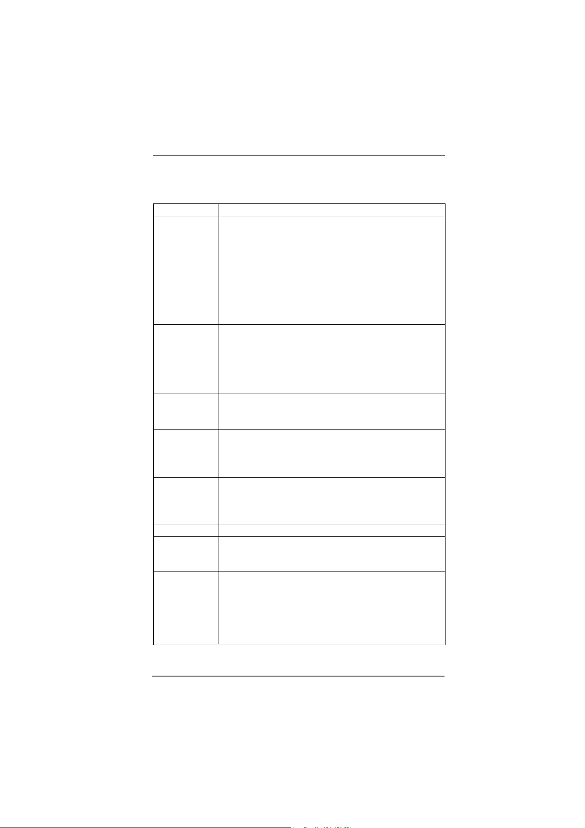
Platform - Micro ATX Form Factor: 9.6-in x 9.6-in, 24.4 cm x 24.4 cm
CPU - 775-Pin Socket supporting Intel® Dual Core Pentium® XE and
Pentium® D / Pentium® 4 / Celeron® D processor
(in 775-land LGA package)
- FSB 1066/800/533 MHz
- Supports EM64T CPU
- Supports Hyper-Threading Technology (see CAUTION 1)
- Supports Untied Overclocking Technology (see CAUTION 2)
Chipset - Northbridge: ATITM Radeon® Xpress 200 chipset
- Southbridge: ULi® 1573
Memory - 2 x DDR DIMM slots
- Support DDR400/333/266
- Max. capacity: 4GB
- 2 x DDRII DIMM slots
- Support DDRII667/533/400
- Max. capacity: 4GB
Hybrid Booster - CPU Frequency Stepless Control (see CAUTION 3)
- ASRock U-COP (see CAUTION 4)
- Boot Failure Guard (B.F.G.)
Expansion Slot - 2 x PCI slots
- 1 x PCI Express x 16 slot
- 1 x PCI Express x 1 slot
- 1 x AMR slot
Graphics - Integrated ATI
- DirectX 9.0 VGA
- Pixel Shader 2.0
- Max. shared memory 128MB
Audio - Realtek ALC850 7.1 channel AC’97 audio codec
LAN - Realtek PHY RTL8201CL
- Speed: 10/100Mb Ethernet
- Supports Wake-On-LAN
Rear Panel I/O ASRock 8CH I/O
- 1 x PS/2 Mouse
- 1 x PS/2 Keyboard Port
- 1 x Serial Port: COM1
- 1 x Parallel Port (ECP/EPP Support)
- 4 x Ready-to-Use USB 2.0 Ports
TM
Radeon® X300 based graphics
66
6
66
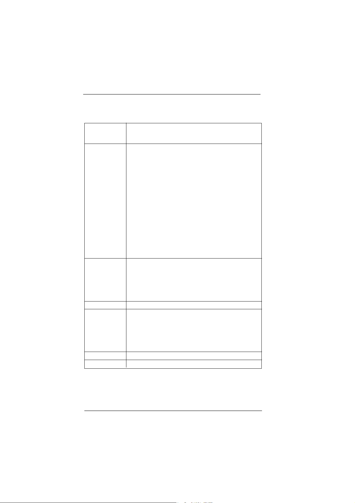
- 1 x RJ-45 Port
- Audio Jack: Side Speaker/Rear Speaker/Central Bass/Line
in/Front Speaker/Microphone (see CAUTION 5)
Connector - 4 x Serial ATA 1.5Gb/s connectors
(Supports RAID 0, 1, JBOD)
(No support for “Hot Plug” function)
- 2 x ATA133 IDE connector (supports 4 x IDE devices)
- 1 x Floppy connector
- 1 x Game header
- 1 x IR header
- 1 x VGA header
- 1 x TV-OUT header
- CPU/Chassis FAN connector
- 20 pin ATX power connector
- 4 pin 12V power connector
- CD in header
- Front panel audio connector
- 2 x USB 2.0 headers (support 4 USB 2.0 ports)
(see CAUTION 6)
BIOS Feature - 4Mb AMI BIOS
- AMI Legal BIOS
- Supports “Plug and Play”
- ACPI 1.1 Compli ance Wake Up Events
- Supports jumperfree
- SMBIOS 2.3.1 Support
Support CD - Drivers, Utilities, AntiVirus Software
Hardware - CPU Temperature Sensing
Monitor - Chassis Temperature Sensing
- CPU Overheat Shutdown to Protect CPU Life
- CPU Fan Tachometer
- Chassis Fan Tachometer
- Voltage Monitoring: +12V, +5V, +3.3V, Vcore
OS - Microsoft® Windows® 2000/XP/XP 64-bit compliant
Certifications - FCC, CE, WHQL
77
7
77

CAUTION!
1. About the setting of “Hyper Threading Technology”, please che ck page 30.
2. This motherboard supports U ntied Overclocking Technology. Please read “Untied Overclocking Technology” on page 25 for details.
3. Although this motherboard offers stepless control, it is not recommended
to perform over-clocking. Frequencies other than the recommended CPU
bus frequencies may cause the instability of the system or damage the
CPU.
4. While CPU overheat is detected, the system will automatically shutdown.
Before you resume the system, please check if the CPU fan on the
motherboard functions properly and unplug the power cord, then plug it
back again. To improve heat dissipation, remember to spray thermal
grease between the CPU and the heatsink when you install the PC system.
5. For microphone input, this motherboard supports both stereo and mono
modes. For audio output, this motherboard supports 2-channel, 4-channel,
6-channel, and 8-channel modes. Please check the table on page 10 for
proper connection.
6. Power Management for USB 2.0 works fine under Microsoft® Windows® XP
SP1 or SP2 / 2000 SP4.
88
8
88
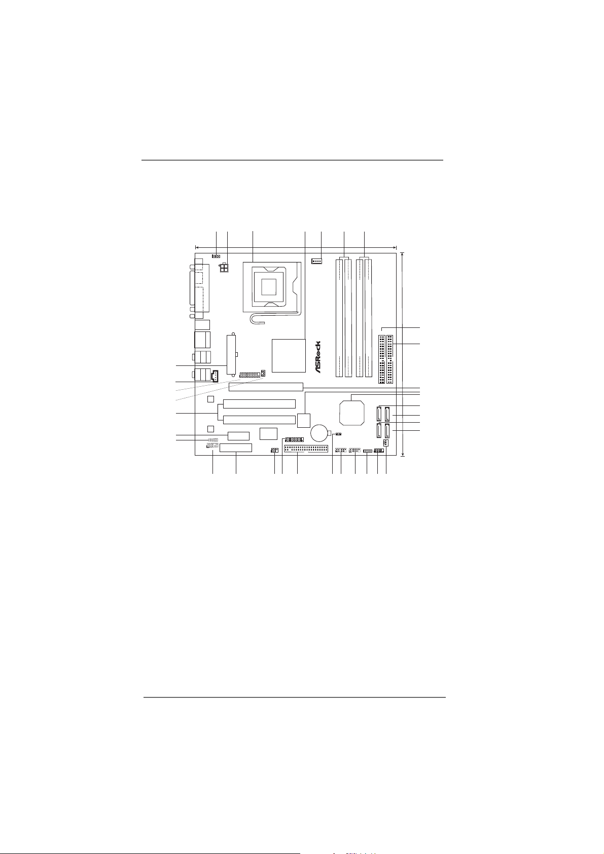
1.3 Motherboard Layout1.3 Motherboard Layout
1.3 Motherboard Layout
1.3 Motherboard Layout1.3 Motherboard Layout
2
1
3
24.4cm (9.6 in)
1
PS2_USB_PWR1
PS2
Mouse
Keyboard
PARALLEL PORT
ATX12V1
PS2
7
6
5
4
DDRII667/DDR400
CPU_FAN1
COM1
Dual CoreCPU
SATA4
SATA2
17
24.4cm (9.6 in)
IDE2
8
9
10
11
12
13
SATA3
SATA1
CHA_FAN1
14
15
16
34
33
32
30
29
28
31
USB2.0
T:USB2
B:USB3
USB2.0
T:USB0
B:USB1
CTRBASS
MICIN
PCI2
PCI1
1
TV-OUT1
PCIE1
PCI
EXPRESS
Super
FSB1066
Radeon
Xpress 200
Chipset
7.1 CH
I/O
IR1
1
24
2526
ATI
1
FLOPPY1
DDRII_1 (64/72bit, 240-pin module)
`
775Twins-HDTV
ULi
22
CLRCMOS1
USB67
1
1573
21
4Mb
BIOS
CMOS
Battery
GAME1
23
Top:
RJ-45
Top:
REARSPK
Bottom:
Center:
SIDESPK
Bottom:
ATXPWR1
Top:
LINEIN
Center:
FRONT
1
1
CD1
VGA1
LAN
PHY
Audio
USB2.0
CODEC
PCIE2
JL1
JR1
AMR1
AUDIO1
27
DDRII_2 (64/72bit, 240-pin module)
USB45
1
20
DDR1 (64/72bit, 184-pin module)
SPEAKER1
1
19
DDR2 (64/72bit, 184-pin module)
PANEL1
PLEDPWRBTN
1
HDLED RESET
18
IDE1
ATA133
SATA
1 PS2_USB_PWR1 Jumper 17 Chassis Fan Connector (CHA_FAN1)
2 A TX 12V Connector (A TX12V1) 18 System Panel Hea der (P ANEL1)
3 775-Pin CPU Socket 19 Chassis Speaker Header (SPEAKER 1)
4 North Bridge Controller 20 USB 2.0 Header (USB45, Blue)
5 CPU Fan Connector (CPU_FAN1) 2 1 USB 2.0 Header (USB67, Blue)
6 2 x 240-pin DDRII DIMM Slots 22 Clear CMOS Jumper (CLRCMOS1)
(DDRII_1, DDRII_2; Yellow) 23 Floppy Connector (FLOPPY1)
7 2 x 184-pin DDR DIMM Slots 24 Game Port Header (GAME1)
(DDR1, DDR2; Blue) 25 Infrared Module Connector (IR1)
8 Primary IDE Connector (IDE1, Blue) 26 AMR Slot (AMR1)
9 Secondary IDE Connector (IDE2, Black) 27 Front Panel Audio Header (AUDIO1)
10 PCI EXPRESS Slot (PCIE1) 28 JR1 / JL1 Jumpers
11 BIOS FWH Chip 29 PCI EXPRESS Slot (PCIE2)
12 South Bridge Controller 30 PCI Slots (PCI1- 2)
13 Fourth Serial A T A Connector (SAT A4, black) 31 TV-OUT Header (TV-OUT1)
14 Third Serial A T A Connector (SAT A3, black) 32 VGA He a der (VGA1)
15 Secondary Serial A TA Connector (SA T A2, black) 3 3 Internal Audio Connector: CD1 (Black)
16 Primary Serial A T A Connector (SATA1, blue) 34 ATX Power Connector (ATXPW R1)
99
9
99
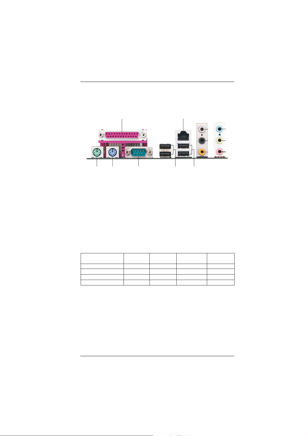
1.41.4
ASRock 8CH I/OASRock 8CH I/O
1.4
ASRock 8CH I/O
1.41.4
ASRock 8CH I/OASRock 8CH I/O
12
3
4
5
13
1 Parallel Port 8 Microphone (Pink)
2 RJ-45 Port 9 USB 2.0 Ports (USB01)
3 Side Speaker (Gray) 10 USB 2.0 Ports (USB23)
4 Rear Speaker (Black) 11 Serial Port: COM1
5 Central / Bass (Orange) 1 2 PS/2 Keyboard Port (Purple)
6 Line In (Light Blue) 13 PS/2 Mouse Port (Green)
*7 Front Speaker (Lime)
* If you use 2-channel speaker, please connect the spea ker’s plug into “Front Speaker Jack”. See
the table below for connection details in accordance with the type of speaker you use.
Audio Output Channels Front Speaker Rear Speaker Central / Bass Side Speaker
12
TABLE for Audio Output Connection
2 V -- -- -4VV---6VVV-8VVVV
11
(No. 7) (No. 4) (No. 5) (No. 3)
910
6
7
8
1010
10
1010
Chapter 2 InstallationChapter 2 Installation
Chapter 2 Installation
Chapter 2 InstallationChapter 2 Installation
775Twins-HDTV is a Micro ATX form factor (9.6" x 9.6", 24.4 x 24.4 cm) motherboard.
Before you install the motherboard, study the configuration of your chassis to
ensure that the motherboard fits into it.
Make sure to unplug the power cord before installing or removing the
motherboard. Failure to do so may cause physical injuries to you and
damages to motherboard components.
2.1 Screw Holes2.1 Screw Holes
2.1 Screw Holes
2.1 Screw Holes2.1 Screw Holes
Place screws into the holes indicated by circles to secure the motherboard to the
chassis.
Do not over-tighten the screws! Doing so may damage the motherboard.
2.2 Pre-installation Precautions2.2 Pre-installation Precautions
2.2 Pre-installation Precautions
2.2 Pre-installation Precautions2.2 Pre-installation Precautions
Take note of the following precautions before you install motherboard components
or change any motherboard settings.
1. Unplug the power cord from the wall socket before touching any component.
2. To avoid damaging the motherboard components due to static electricity, NEVER
place your motherboard directly on the carpet or the like. Also remember to use
a grounded wrist strap or touch a safety grounded object before you handle
components.
3. Hold components by the edges and do not touch the ICs.
4. Whenever you uninstall any component, place it on a grounded antistatic pad or
in the bag that comes with the component.
Before you install or remove any component, ensure that the power is
switched off or the power cord is detached from the power supply.
Failure to do so may cause severe damage to the motherboard, peripherals,
and/or components.
1111
11
1111
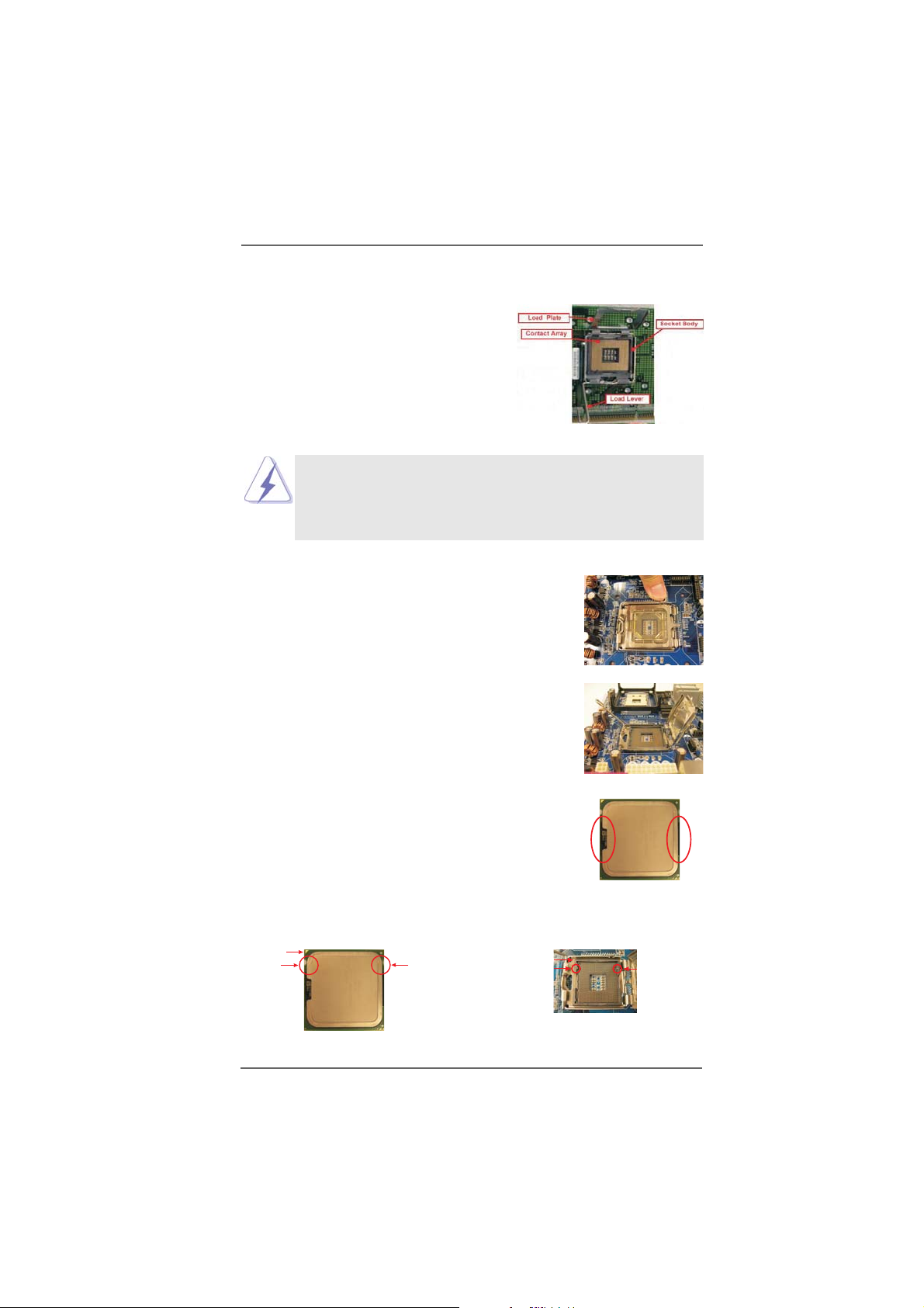
2.3 775-LAND CPU Installation2.3 775-LAND CPU Installation
2.3 775-LAND CPU Installation
2.3 775-LAND CPU Installation2.3 775-LAND CPU Installation
For the installation of Intel 775-LAND CPU,
please follow the steps below.
Before you insert the 775-LAND CPU into the socket, please check if
the CPU surface is unclean or if there is any bent pin on the socket.
Do not force to insert the CPU into the socket if above situation is
found. Otherwise, the CPU will be seriously damaged.
Step 1. Open the socket:
Step 1-1. Disengaging the lever by depressing
down and out on the hook to clear
retention tab.
Step 1-2. Rotate the load lever to fully open po-
sition at approximately 135 degrees.
Step 1-3. Rotate the load plate to fully open po-
sition at approximately 100 degrees.
775-Pin Socket Overview
Step 2. Insert the 775-LAND CPU:
Step 2-1. Hold the CPU by the edges where are
marked with black lines.
Step 2-2. Orient the CPU with IHS (Integrated
Heat Sink) up. Locate Pin1 and the two
orientation key notches.
Pin1
orientation
key notch
775-LAND CPU
orientation
key notch
1212
12
1212
Pin1
alignment key
black line
775-Pin Socket
black line
alignment key
For proper inserting, please ensure to match the two orientation key
notches of the CPU with the two alignment keys of the socket.
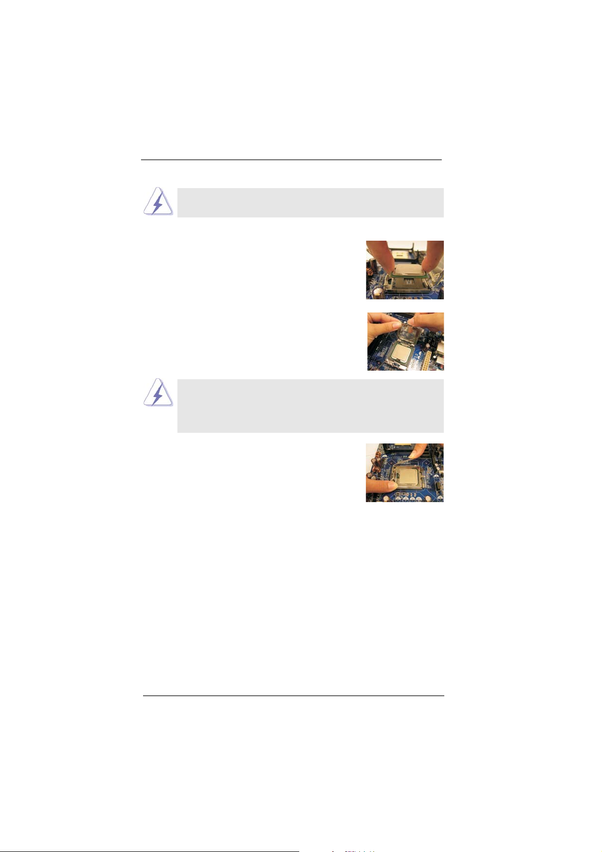
Step 2-3. Carefully place the CPU into the socket
by using a purely vertical motion.
Step 2-4. Verify that the CPU is within the socket
and properly mated to the orient keys.
Step 3. Remove PnP Cap (Pick and Pla ce Cap):
Use your left hand index finger and thumb to
support the load plate edge, engage PnP cap
with right hand thumb and peel the cap from the
socket while pressing on center of PnP cap to
assist in removal.
1. It is recommended to use the cap tab to handle and avoid kicking
off the PnP cap.
2. This cap must be placed if returning the motherboard for after
service.
Step 4. Close the socket:
Step 4-1. Rotate the load plate onto the IHS.
Step 4-2. While pressing down lightly on load
plate, engage the load lever.
Step 4-3. Secure load lever with load plate tab
under retention tab of load lever.
1313
13
1313
 Loading...