

Page 1

775S61
User Manual
Version 1.0
Published September 2004
Copyright©2004 ASRock INC. All rights reserved.
11
1
11
Page 2

Copyright Notice:Copyright Notice:
Copyright Notice:
Copyright Notice:Copyright Notice:
No part of this manual may be reproduced, transcribed, transmitted, or translated in
any language, in any form or by any means, except duplication of documentation by
the purchaser for backup purpose, without written consent of ASRock Inc.
Products and corporate names appearing in this manual may or may not be registered trademarks or copyrights of their respective companies, and are used only for
identification or explanation and to the owners’ benefit, without intent to infringe.
Disclaimer:Disclaimer:
Disclaimer:
Disclaimer:Disclaimer:
Specifications and information contained in this manual are furnished for informational use only and subject to change without notice, and should not be constructed
as a commitment by ASRock. ASRock assumes no responsibility for any errors or
omissions that may appear in this manual.
With respect to the contents of this manual, ASRock does not provide warranty of
any kind, either expressed or implied, including but not limited to the implied warranties or conditions of merchantability or fitness for a particular purpose.
In no event shall ASRock, its directors, officers, employees, or agents be liable for
any indirect, special, incidental, or consequential damages (including damages for
loss of profits, loss of business, loss of data, interruption of business and the like),
even if ASRock has been advised of the possibility of such damages arising from a n y
defect or error in the manual or product.
ASRock Website: http://www.asrock.com
22
2
22
Page 3

ContentsContents
Contents
ContentsContents
1 Introduction1 Introduction
1 Introduction
1 Introduction1 Introduction
1.1 Package Contents........................................................... 4
1.2 Specifications ................................................................. 5
1.3 Motherboard Layout ....................................................... 7
1.4 ASRock I/OTM................................................................... 8
2 Installation2 Installation
2 Installation
2 Installation2 Installation
2.1 Screw Holes ................................................................... 9
2.2 Pre-installation Precautions ............................................ 9
2.3 CPU Installation ............................................................... 1 0
2.4 Installation of Heatsink and CPU fan .............................. 12
2.5 Installation of Memory Modules (DIMM) .......................... 13
2.6 Expansion Slots .............................................................. 1 4
2.7 Jumpers Setup................................................................ 15
2.8 Onboard Headers and Connectors ................................ 16
3 BIOS Setup3 BIOS Setup
3 BIOS Setup
3 BIOS Setup3 BIOS Setup
3.1 BIOS Setup Utility ............................................................ 18
3.1.1 BIOS Menu Bar ..................................................... 18
3.1.2 Legend Bar ........................................................... 18
3.2 Main Menu ....................................................................... 19
3.3 Advanced, Security, Power, Boot, and Exit Menus ...... 2 1
4 Software Support4 Software Support
4 Software Support
4 Software Support4 Software Support
4.1 Installing Operating System ............................................ 2 2
4.2 Support CD Information ................................................... 22
4.2.1 Running Support CD ............................................. 22
4.2.2 Drivers Menu ........................................................ 22
4.2.3 Utilities Menu ......................................................... 2 2
4.2.4 ASRock “PC-DIY Live De mo” Program ................. 22
4.2.5 “LGA 775 CPU Installation Live Demo” Program...... 22
4.2.6 Contact Information ............................................... 22
AppendixAppendix
Appendix
AppendixAppendix
1. Advanced Menu ............................................................. 2 3
2. Security Menu................................................................. 28
3. Power Menu ................................................................... 29
4. Boot Menu ....................................................................... 30
5. Exit Menu ......................................................................... 31
........................................................................................................
....................................................
........................................................................................................
............................................................................................................
......................................................
............................................................................................................
............................................................................................................
......................................................
............................................................................................................
......................................................................................
...........................................
......................................................................................
......................................................................................................................
...........................................................
......................................................................................................................
4 4
4
4 4
9 9
9
9 9
18 18
18
18 18
22 22
22
22 22
23 23
23
23 23
33
3
33
Page 4

Chapter 1 IntroductionChapter 1 Introduction
Chapter 1 Introduction
Chapter 1 IntroductionChapter 1 Introduction
Thank you for purchasing ASRock 775S61 motherboard, a reliable motherboard
produced under ASRock’s consistently stringent quality control. It delivers excellent
performance with robust design conforming to ASRock’s commitment to quality and
endurance.
Chapter 1 and 2 of this manual contain introduction of the motherboard and step-bystep installation guide for new DIY system builders. Chapter 3 and 4 contain basic
BIOS setup and Support CD information. For advanced users’ reference, the Appendix appearing on page 23 offers more advanced BIOS setup information.
Because the motherboard specifications and the BIOS software
might be updated, the content of this manual will be subject to
change without notice. In case any modifications of this manual
occur, the updated version will be available on ASRock website
without further notice. You may find the latest memory and CPU
support lists on ASRock website as well.
ASRock website http://www.asrock.com
1.1 Package Contents1.1 Package Contents
1.1 Package Contents
1.1 Package Contents1.1 Package Contents
ASRock 775S61 Motherboard
(Micro ATX Form Factor: 9.6-in x 9.0-in, 24.4 cm x 22.9 cm)
ASRock 775S61 Quick Installation Guide
ASRock 775S61 Support CD (including LGA 775 CPU Installation Live Demo)
One 80-conductor Ultra ATA 66/100/133 IDE Ribbon Cable
One Ribbon Cable for a 3.5-in Floppy Drive
One ASRock I/OTM Shield
One COM Port Bracket
One ASRock MR Card (Optional)
44
4
44
Page 5

1.2 Specifications1.2 Specifications
1.2 Specifications
1.2 Specifications1.2 Specifications
Platform: Micro ATX Form Factor: 9.6-in x 9.0-in, 24.4 cm x 22.9 cm
CPU: 775-Pin Socket
supporting Intel® Pentium® 4 / Celeron® processor (in 775-land
LGA package)
Chipsets: North Bridge:
SiS 661FX chipset, FSB @ 800/533MHz,
supports Hyper-Threading Technology (see CAUTION 1)
South Bridge:
SiS 963L chipset, supports USB 2.0, ATA 133
VGA: SiS Real256E, 32MB-64MB VRAM (share memory)
Memory: 3 DDR DIMM slots: DDR1, DDR2, and DDR3
PC2100 (DDR266) for 3 DDR DIMM slots, Max. 3GB;
PC2700 (DDR333) for 2 DDR DIMM slots, Max. 2GB;
PC3200 (DDR400) for 1 DDR DIMM slots, Max. 1GB
IDE: IDE1: ATA 133 / Ultra DMA Mode 6;
IDE2: ATA 133 / Ultra DMA Mode 6;
Supports up to 4 IDE devices
Floppy Port: Supports up to 2 floppy disk drives
Audio: 6 channels AC’97 Audio
LAN: Speed: 802.3u (10/100 Ethernet), supports Wake-On-LAN
Hardware Monitor: CPU temperature sensing;
Chassis temperature sensing;
CPU overheat shutdown to protect CPU life (ASRock U-COP)
(see CAUTION 2);
CPU fan tachometer; Chassis fan tachometer;
Voltage monitoring: +12V, +5V, +3.3V, Vcore
PCI slots: 3 slots with PCI Specification 2.2, PCI3 slot shared with AMR
AGP slot: 1 AGP slot, AGP 3.5 compliant,
supports 1.5V, 8X / 4X AGP card (see CAUTION 3)
AMR slot: 1 slot, supports ASRock MR card
USB 2.0: 6 USB 2.0 ports:
includes 4 default USB 2.0 ports on the rear panel,
plus one header to support 2 additional USB 2.0 ports
(see CAUTION 4)
ASRock I/OTM: 1 PS/2 keyboard port, 1 PS/2 mouse port;
1 V GA port; 1 parallel port: ECP/EPP support;
55
5
55
Page 6

1 RJ 45 port; 4 default USB 2.0 ports;
Audio Jack: Line Out / Line In / Microphone + Game port
BIOS: AMI legal BIOS; Supports “Plug and Play”;
ACPI 1.1 compliance wake up events;
CPU frequency stepless control
(only for advanced users’ reference, see CAUTION 5)
OS: Microsoft® Windows® 98SE / ME / 2000 / XP compliant
CAUTION!
1. About the setting of “Hyper Threading Technology”, please check page 23.
2. While CPU overheat is detected, the system will automatically shutdown.
Please check if the CPU fan on the motherboard functions properly
before you resume the system. To improve heat dissipation, remember to
spray thermal grease between the CPU and the heatsink when you install
the PC system.
3. Do NOT use a 3.3V AGP card on the AGP slot of 775S61 motherboard!
It may cause permanent damage!
4. Power Management for USB 2.0 works fine under Microsoft® Windows
XP SP1/2000 SP4. It may not work properly under Microsoft® Windows
98/ME. Please refer to Microsoft® official document at
http://www.microsoft.com/whdc/hwdev/bus/USB/USB2support.mspx
5. Although 775S61 offers stepless control, it is not recommended to perform
over clocking. When the CPU frequency of 775S61 is set to perform over
clocking, other clocks, such as PCI clock, AGP clock and Memory clock
will also be overclocked proportionally. Frequencies other than the
recommended CPU bus frequencies may cause the instability of the
system or damage the CPU and the motherboard.
®
®
66
6
66
Page 7
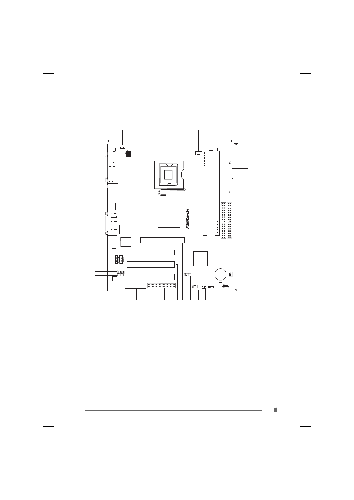
1.3 Motherboard Layout1.3 Motherboard Layout
1.3 Motherboard Layout
1.3 Motherboard Layout1.3 Motherboard Layout
25
24
23
22
21
PS/2
Mouse
PS/2
Keyboard
VGA
USB 2.0
Ports
USB 2.0
Ports
GAME AUDIO1
GAME AUDIO1
LAN
Lineout
Linein
Line
In
Mic
Micin
In
LAN
PHY
AUDIO
CODEC
2
1
22.9cm (9.0 in)
PS2_USB_PWR1
1
ATX12V1
PARALLEL PORT
2Mb
BIOS
Super
I/O
CD1
AUX1
AUDIO1
JL11JR1
AMR1
PCI 1
PCI 2
PCI 3
FLOPPY1
661FX
Chipset
1.5V_AGP1
775S61
SIS
4
3
5
CPU_FAN1
6
7
ATXPWR1
8
`
Prescott 800
USB45
1
1
DDR400 FSB800
SIS
963L
5.1CH
USB2.0
COM1
IR1
DDR DIMM1(64/72 bit, 184-pinmodule)
10
SPEAKER1
1
DDR DIMM2(64/72 bit, 184-pinmodule)
32
DDR DIMM3(64/72 bit, 184-pinmodule)
54
IDE2 IDE1
ATA133
CMOS
Battery
1
PLED PWRBTN
HDLED RST
PANEL1
1
CHA_FAN1
9
24.4cm (9.6 in)
10
11
20
19
18
17
16
15
14
13
12
1 PS2_USB_PWR1 Jumper 14 Infrared Module Connector (IR1)
2 A TX 12V Connector (A TX12V1) 15 Serial Port Connector (COM1)
3 775-Pin CPU Socket 16 USB 2.0 Header (USB45, Blue)
4 North Bridge Controller 17 AGP Slot (1.5V_AGP1)
5 CPU Fan Connector (CPU_FAN1) 18 PCI Slots (PCI1- 3)
6 184-pin DDR DIMM Slots (DDR DIMM1- 3) 1 9 Floppy Connector (FLOPPY1)
7 ATX Power Connector (ATXPWR1) 20 AMR Slot (AMR1)
8 Secondary IDE Connector (IDE2, Black) 21 JR1 / JL1 Jumpers
9 Primary IDE Connector (IDE1, Blue) 22 Front Panel Audio Connector (AUDIO1)
10 South Bridge Controller 23 Internal Audio Connector: CD1 (Black)
11 Chassis Fan Connector (CHA_FAN1) 24 Internal Audio Connector: AUX1 (White)
12 System Panel Connector (P ANEL1) 25 Flash Memor y
13 External Speaker Connector (SPEAKER1)
77
7
77
Page 8
TMTM
TM
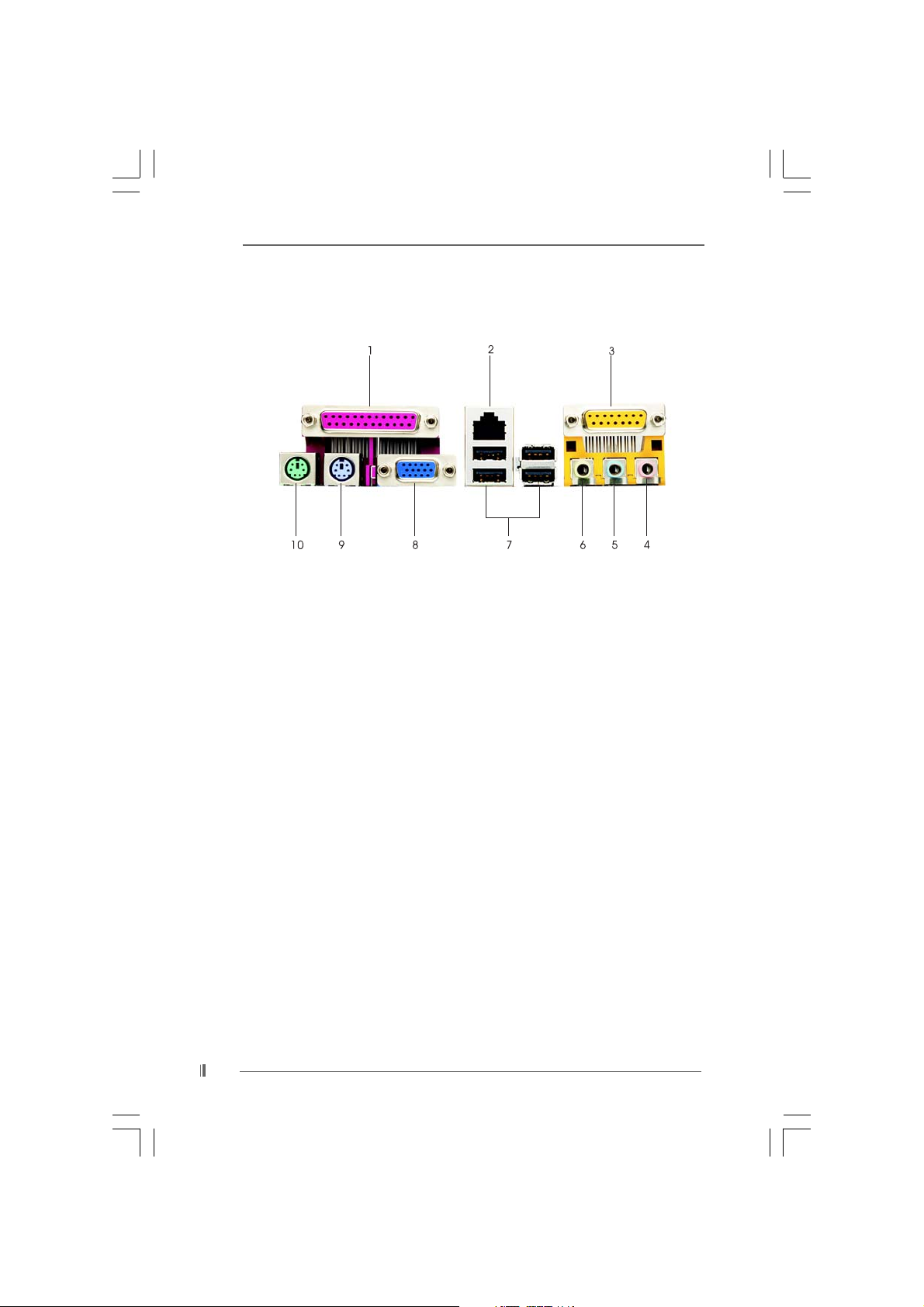
1.4 ASRock I/O1.4 ASRock I/O
1.4 ASRock I/O
1.4 ASRock I/O1.4 ASRock I/O
1 Parallel Port 6 Line Out (Lime)
2 RJ-45 Port 7 USB 2.0 Ports
3 Game Port 8 V GA Port
4 Microphone (Pink) 9 PS/2 Keyboard Port (Purple)
5 Line In (Light Blue) 10 PS/2 Mouse Port (Green)
TMTM
88
8
88
Page 9

Chapter 2 InstallationChapter 2 Installation
Chapter 2 Installation
Chapter 2 InstallationChapter 2 Installation
775S61 is a Micro ATX form factor (9.6" x 9.0", 24.4 x 22.9 cm) motherboard. Before
you install the motherboard, study the configuration of your chassis to
ensure that the motherboard fits into it.
Make sure to unplug the power cord before installing or removing the
motherboard. Failure to do so may cause physical injuries to you and
damages to motherboard components.
2.1 Screw Holes2.1 Screw Holes
2.1 Screw Holes
2.1 Screw Holes2.1 Screw Holes
Place screws into the holes indicated by circles to secure the motherboard to the
chassis.
Do not over-tighten the screws! Doing so may damage the motherboard.
2.2 Pre-installation Precautions2.2 Pre-installation Precautions
2.2 Pre-installation Precautions
2.2 Pre-installation Precautions2.2 Pre-installation Precautions
Take note of the following precautions before you install motherboard components
or change any motherboard settings.
1. Unplug the power cord from the wall socket before touching any component.
2. To avoid damaging the motherboard components due to static electricity, NEVER
place your motherboard directly on the carpet or the like. Also remember to use
a grounded wrist strap or touch a safety grounded object before you handle
components.
3. Hold components by the edges and do not touch the ICs.
4. Whenever you uninstall any component, place it on a grounded antistatic pad or
in the bag that comes with the component.
Before you install or remove any component, ensure that the power is
switched off or the power cord is detached from the power supply.
Failure to do so may cause severe damage to the motherboard, peripherals,
and/or components.
99
9
99
Page 10
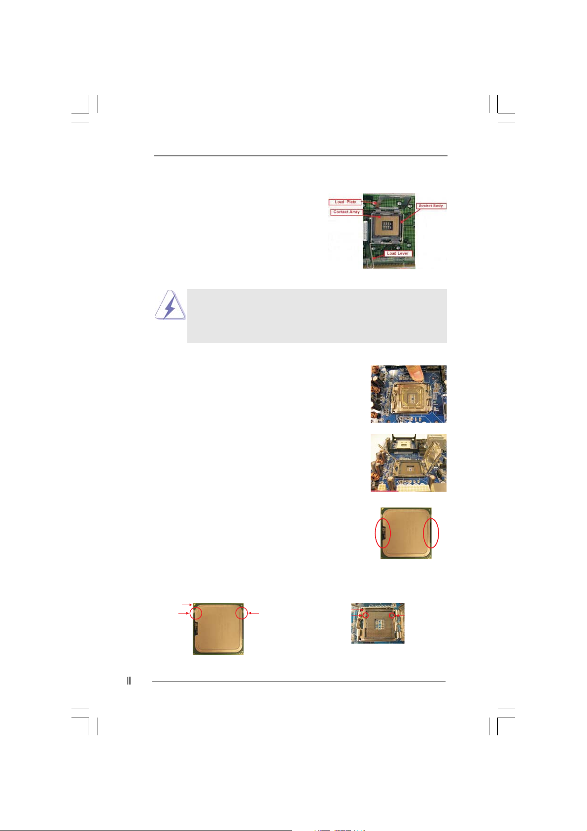
2.3 CPU Installation2.3 CPU Installation
2.3 CPU Installation
2.3 CPU Installation2.3 CPU Installation
For the installation of Intel 775-Pin CPU,
please follow the steps below.
Before you insert the 775-Pin CPU into the socket, please check if the
CPU surface is unclean or if there is any bent pin on the socket. Do
not force to insert the CPU into the socket if above situation is found.
Otherwise, the CPU will be seriously damaged.
Step 1. Open the socket:
Step 1-1. Disengaging the lever by depressing
down and out on the hook to clear
retention tab.
Step 1-2. Rotate the load lever to fully open po-
sition at approximately 135 degrees.
Step 1-3. Rotate the load plate to fully open po-
sition at approximately 100 degrees.
775-Pin Socket Overview
Step 2. Insert the 775-Pin CPU:
Step 2-1. Hold the CPU by the edges where are
marked with black lines.
Step 2-2. Orient the CPU with IHS (Integrated
Heat Sink) up. Locate Pin1 and the two
orientation key notches.
Pin1
orientation
key notch
775-Pin CPU
1010
10
1010
orientation
key notch
Pin1
alignment key
black line
775-Pin Socket
black line
alignment key
Page 11

For proper inserting, please ensure to match the two orientation key
notches of the CPU with the two alignment keys of the socket.
Step 2-3. Carefully pla ce the CPU into the socket
by using a purely vertical motion.
Step 2-4. Verify that the CPU is within the socket
and properly mated to the orient keys.
Step 3. Remove PnP Cap (Pick a nd Pla ce Cap):
Use your left hand index finger and thumb to
support the load plate edge, engage PnP cap
with right hand thumb and peel the cap from the
socket while pressing on center of PnP cap to
assist in removal.
It is recommended to use the cap tab to handle and avoid kicking off
the PnP cap.
Step 4. Close the socket:
Step 4-1. Rotate the load plate onto the IHS.
Step 4-2. While pressing down lightly on load
plate, engage the load lever.
Step 4-3. Secure load lever with load plate tab
under retention tab of load lever.
1111
11
1111
Page 12

2.42.4
Installation of CPU Fan and HeatsinkInstallation of CPU Fan and Heatsink
2.4
Installation of CPU Fan and Heatsink
2.42.4
Installation of CPU Fan and HeatsinkInstallation of CPU Fan and Heatsink
This motherboard is equipped with 775-Pin socket that supports Intel 775-Pin CPU.
Please a dopt the type of he atsink and cooling fan complia nt with Intel 775-Pin CPU to
dissipate heat. Before you installed the heatsink, you need to spray thermal interface
material between the CPU and the heatsink to improve heat dissipation. Ensure that
the CPU and the heatsink are securely fastened and in good contact with each other.
Then connect the CPU fan to the CPU_FAN connector (CPU_FAN1, see page 7,
No. 5).
For proper installation, please kindly refer to the instruction manuals of
your CPU fan and heatsink.
Below is an example to illustrate the installation of the heatsink for 775-Pin CPU.
Step 1. Apply thermal interface material onto center
of IHS on the socket surface.
Step 2. Place the heatsink onto the socket. Ensure
fan cables are oriented on side closest to the
CPU fan connector on the motherboard
(CPU_FAN1, see page 7, No. 5).
Step 3. Align fasteners with the motherboard
throughholes.
Step 4. Rotate the fastener clockwise, then press
down on fastener caps with thumb to install
and lock. Repeat with remaining fasteners.
If you press down the fasteners without rotating them clockwise,
the heatsink cannot be secured on the motherboard.
Step 5. Connect fan header with the CPU fan
connector on the motherboard.
Step 6. Secure excess cable with tie-wrap to ensure
cable does not interfere with fan operation or
contact other components.
1212
12
1212
Page 13

2.5 Installation of Memory Modules (DIMM)2.5 Installation of Memory Modules (DIMM)
2.5 Installation of Memory Modules (DIMM)
2.5 Installation of Memory Modules (DIMM)2.5 Installation of Memory Modules (DIMM)
775S61 motherboard provides three 184-pin DD R (Double Data Rate) DIMM slots.
Please make sure to disconnect power supply before adding or
removing DIMMs or the system components.
Step 1. Unlock a DIMM slot by pressing the retaining clips outward.
Step 2. Align a DIMM on the slot such that the notch on the DIMM matche s the bre a k
on the slot.
notch
break
notch
break
The DIMM only fits in one correct orientation. It will cause permanent
damage to the motherboard and the DIMM if you force the DIMM into the
slot at incorrect orientation.
Step 3. Firmly insert the DIMM into the slot until the retaining clips at both ends fully
snap back in place and the DIMM is properly seated.
1313
13
1313
Page 14

2.6 Expansion Slots (PCI, AMR, and AGP Slots)2.6 Expansion Slots (PCI, AMR, and AGP Slots)
2.6 Expansion Slots (PCI, AMR, and AGP Slots)
2.6 Expansion Slots (PCI, AMR, and AGP Slots)2.6 Expansion Slots (PCI, AMR, and AGP Slots)
There are 3 PCI slots, 1 AMR slot, and 1 AGP slot on 775S61 motherboard.
PCI slots: The PCI slots are used to install expansion cards that have the 32-bit
PCI interface.
AMR slot: The AMR slot is used to insert an ASRock MR card with v.92 Modem
functionality.
AGP slot: The AGP slot is AGP 3.5 compliant and it supports an 8X / 4X AGP
card.
Do NOT use a 3.3V AGP card on the AGP slot of 775S61 motherboard!
It may cause permanent damage!
Installing an expansion cardInstalling an expansion card
Installing an expansion card
Installing an expansion cardInstalling an expansion card
Step 1. Before installing the expansion card, please make sure that the power
supply is switched off or the power cord is unplugged. Please read the
documentation of the expansion card and make necessary hardware
settings for the card before you start the installation.
Step 2. Remove the system unit cover (if your motherboard is already installed in a
chassis).
Step 3. Remove the bracket facing the slot that you intend to use. Keep the screws
for later use.
Step 4. Align the card connector with the slot and press firmly until the card is
completely seated on the slot.
Step 5. Fasten the card to the chassis with screws.
Step 6. Replace the system cover.
1414
14
1414
Page 15

2.7 Jumpers Setup2.7 Jumpers Setup
2.7 Jumpers Setup
2.7 Jumpers Setup2.7 Jumpers Setup
The illustration shows how jumpers are
setup. When the jumper cap is placed on
pins, the jumper is “SHORT”. If no jumper ca p
is placed on pins, the jumper is “OPEN”. The
illustration shows a 3-pin jumper whose pin1
and pin2 are “SHORT” when jumper cap is
placed on these 2 pins.
Jumper Setting Description
PS2_USB_PWR1 Short pin2, pin3 to enable
(see p.7 item 1) +5VSB (standby) for PS/2 or
1_2
+5V
2_3
+5VSB
USB wake up events.
Note: To select +5VSB, it requires 2 Amp and higher standby current provided by
power supply.
JR1(see p.7 item 21)
JL1(see p.7 item 21)
JR1 J L1
Note: If the jumpers JL1 and JR1 are short, both front panel and rear panel audio
connectors can work.
1515
15
1515
Page 16

2.8 Onboard Headers and Connectors2.8 Onboard Headers and Connectors
2.8 Onboard Headers and Connectors
2.8 Onboard Headers and Connectors2.8 Onboard Headers and Connectors
Connectors are NOT jumpers. DO NOT pla ce jumper caps over
these connectors.
FDD Connector
(33-pin FLOPPY1)
(see p.7, No. 19)
Pin1
FLOPPY1
the red-striped side to Pin1
Note: Make sure the red-striped side of the cable is plugged into Pin1 side of the
connector.
Primary IDE Connector (Blue) Secondary IDE Connector (Black)
(39-pin IDE1, see p.7, No. 9) (39-pin IDE2, see p.7, No. 8)
PIN1
IDE1
connect the blue end
to the motherboard
PIN1
IDE2
connect the black end
to the IDE devices
80-conductor ATA 66/100/133 ca bl e
Note: If you use only one IDE device on this motherboard, please set the IDE
device as “Master”. Please refer to the instruction of your IDE device vendor
for the details. Besides, to optimize compatibility and performance, please
connect your hard disk drive to the primary IDE connector (IDE1, blue) and
CD-ROM to the secondary IDE connector (IDE2, black).
USB 2.0 Header ASRock I/O PlusTM provides you
(9-pin USB45) 6 ready-to-use USB 2.0 ports on
(see p.7, No. 16) the rear panel. If the rear USB
Infrared Module Header This header supports an optional
(5-pin IR1) wireless transmitting and
(see p.7, No. 14) receiving infrared module.
Internal Audio Connectors These connectors allow you
(4-pin CD1, 4-pin AUX1) to receive stereo audio input
(CD1: see p.7, No. 23) from sound sources such as
(AUX1: see p.7, No. 24) a CD-ROM, D V D-ROM, TV
1
AUX- R
GND
GND
AUX- L
USB_PWR
P-5
P-4
USB_PWR
IRTX
1
IRRX
AUX1
P+5
P+4
+5V
GND
GND
DUMMY
GND
DUMMY
CD- R
GND
GND
CD-L
ports are not sufficient, this
USB 2.0 header is available to
support 2 extra USB 2.0 ports.
CD1
tuner card, or MPEG card.
1616
16
1616
Page 17

1
1
1
GND
+5VA
MIC-POWER
MIC
PLED+
PLED-
HDLED-
HDLED+
+5V
BACKOUT-R
AUD-OUT- R
PWRBTN#
GND
RESET#
GND
DUMMY
DUMMY
BACKOUT-L
AUD-OUT- L
GND
DUMMY
SPEAKER
control of audio devices.
Front panel audio connector This is an interface for front
(9-pin AUDIO1) panel audio cable that allows
(see p.7 item 22) convenient connection and
System panel connector This connector accommo-
(9-pin PANEL1) dates several system front
(see p.7 item 12) panel functions.
Chassis speaker connector This connector allows you
(4-pin SPEAKER 1) to attach to the chassis
(see p.7 item 13) speaker.
Chassis fan connector Connect the fan cable to the
(3-pin CHA_FAN1) connector matching the black
(see p.7 item 11) wire to the ground pin.
GND
+12V
CHA_FAN_SPEED
CPU fan connector Connect the fan cable to the
(4-pin CPU_FAN1) connector matching the black
(see p.7 item 5) wire to the ground pin.
+12V
CPU_FAN_SPEED
N/C
GND
ATX power connector Connect an ATX power
(20-pin ATXPWR1) supply to the connector.
(see p.7 item 7)
1
RRXD1
DDTR#1
TTXD1
DDCD#1
DDSR#1
CCTS#1
RRTS#1
GND
RRI#1
Serial port connector This COM1 connector
(9-pin COM1) supports a serial port module.
(see p.7 item 15)
ATX 12V Connector Please note that it is necessary
(4-pin A TX12V1) to connect a power supply with
(see p.7 No. 2) ATX 12V plug to this connector
so that it can provides sufficient
power. Failing to do so will cause
the failure to power up.
1717
17
1717
Page 18

Chapter 3 BIOS SetupChapter 3 BIOS Setup
Chapter 3 BIOS Setup
Chapter 3 BIOS SetupChapter 3 BIOS Setup
3.1 BIOS Setup Utility3.1 BIOS Setup Utility
3.1 BIOS Setup Utility
3.1 BIOS Setup Utility3.1 BIOS Setup Utility
This section explains how to configure your system using the BIOS Setup Utility. The
Flash Memory on the motherboard stores the BIOS Setup Utility. When you start up
the computer, there is a chance for you to run the BIOS Setup. Press <F2> during the
Power-On-Self-Test (POST) to enter the BIOS Setup Utility, otherwise, POST
continues with its test routines.
If you wish to enter the BIOS Setup after POST, restart the system by pressing
<Ctl> + <Alt> + <Delete>, or by pressing the reset button on the system chassis. You
can also restart by turning the system off and then back on.
The BIOS Setup Utility is designed to be user-friendly. It is a menu-driven program,
which allows you to scroll through its various sub-menus and select among the
predetermined choices.
Because the BIOS software is constantly being updated, the
following BIOS setup screens and descriptions are for reference
purpose only, and may not exactly match what you see on your
screen.
3.1.1 BIOS Menu Bar3.1.1 BIOS Menu Bar
3.1.1 BIOS Menu Bar
3.1.1 BIOS Menu Bar3.1.1 BIOS Menu Bar
The top of the screen has a menu bar with the following selections:
MAIN Sets up the basic system configuration
ADVANCED Sets up the advanced features
SECURITY Sets up the security features
POWER Configures Power Management features
BOOT Configures the default system device that is used
to locate and load the Operating System
EXIT Exits the current menu or the BIOS Setup
To access the menu bar items, press the right or left arrow key on the keyboard
until the desired item is highlighted.
3.1.2 Legend Bar3.1.2 Legend Bar
3.1.2 Legend Bar
3.1.2 Legend Bar3.1.2 Legend Bar
At the bottom of the Setup Screen is a legend bar. The following table lists the keys
in the legend bar with their corresponding functions.
1818
18
1818
Page 19

Navigation Key(s) Function Description
<F1> Displays the General Help Screen
<ESC> Jumps to the Exit menu or returns to the upper menu
from the current menu
/ Moves cursor up or down between fields
/ Selects menu to the left or right
+ / - Increases or decreases values
<Enter> Brings up a selected menu for a highlighted field
<F9> Loads all the setup items to default value
<F10> Saves changes and exits Setup
3.2 Main Menu3.2 Main Menu
3.2 Main Menu
3.2 Main Menu3.2 Main Menu
When you enter the BIOS Setup Utility, the following screen appears.
Advanced
Main
System Date
System Time
Floppy Drives
IDE Devices
BIOS Version
Processor Type
Processor Speed
Cache Size
Microcode Update
TotalMemory
DDR1
DDR2
DDR3
F1:Help
Esc:Exit
AMIBIOS SETUPUTILITY -VERSION 3.31a
Security
1 2004 Wed
Sep
20:07:40
775S61 BIOS P1.00
Intel (R) CPU
2933 MHz
256 KB
F41/05
1024 MBwith 64 MBShared Memory
512 MB/ 166 MHz (DDR333)
512 MB/ 166 MHz (DDR333)
None
:Select Item
:Select Menu
Power
+/-:Change Values
Enter:Select
Boot
Exit
Sub-Menu
[ Setup Help ]
Month: Jan - Dec
Day: 01-31
Year:1980-2099
F9:Setup Defaults
F10:Save &Exit
System Date [Month/Day/Year]
Set the system date that you specify. Valid values for month, day, and year are
Month: (Jan to Dec), Day: (1 to 31), Year: (up to 2099). Use keys to move
between the Month, Day and Year fields.
System Time [Hour:Minute:Second]
Set the system to the time that you specify. Use keys to move between
the Hour, Minute and Second fields.
Floppy Drives
Use this to set the type of floppy drives installed.
IDE Devices
Use this to configure IDE devices.
1919
19
1919
Page 20

TYPE
AMIBIOS SETUP UTILITY - VERSION 3.31a
Main
Type
Cylinders
Heads
Write Precompensation
Sectors
Maximum Capacity
LBA Mode
Block Mode
Fast Programmed I/O Modes
32 Bit Transfer Mode
Ultra DMA Mode
[ Setup Help ]
F1:Help
Esc:Previous Menu
F9:Setup Defaults
F10:Save & Exit
+/-:Change Values
Enter:Select
Sub-Menu
:Select Item
Primary IDEMaster:
On
On
Auto
On
Auto
Select how to set the
parameters of drive,
Or
Select [AUTO] to set
all HDD parameters
automatically.
Auto
To set the type of the IDE device, first, please select “IDE Devices” on Main
menu and press <Enter> to get into the sub-menu. Then, select among
“Primary IDE Master”, “Primary IDE Slave”, “Secondary IDE Master”, and
“Secondary IDE Slave” to make configuration of its type. Below are the
configuration options.
[USER]: It allows user to manually enter the number of cylinders, heads,
and sectors per track for the drive.
Before attempting to configure a hard disk drive, make sure you
have the correct configuration information supplied by the drive
manufacturer. Incorrect settings may cause the system to fail
to recognize the installed hard disk.
2020
20
2020
[Auto]: Select [Auto] to automatically detect hard disk drive. If auto-
detection is successful, the BIOS Setup automatically fills in the
correct values for the remaining fields on this sub-menu. If the autodetection fails, it may due to that the hard disk is too old or too new.
If the hard disk was already formatted on an older system, the BIOS
Setup may detect incorrect parameters. In these cases, select [User]
to manually enter the IDE hard disk drive parameters.
After entering the hard disk information into BIOS, use a disk utility,
such as FDISK, to partition and format new IDE hard disk drives.
This is necessary so that you can write or read data from the hard
disk. Make sure to set the partition of the Primary IDE hard disk
drives to active.
Page 21

[CD/DVD]: This is used for IDE CD/D VD drives.
[ARMD]: This is used for IDE ARMD (ATAPI Removable Media Device),
such as MO.
Cylinders
This is used to configure the number of cylinders. Refer to the drive
documentation to determine the correct value.
Heads
This is used to configure the number of read/write heads. Refer to the
drive documentation to determine the correct values.
Write Pre-compensation
Enter Write Pre-compensation sector. Refer to the drive documentation to
determine the correct value.
Sectors
This is used to configure the number of sectors per track. Refer to the
drive documentation to determine the correct value.
Maximum Capacity
This field shows the drive’s maximum capacity as calculated by the BIOS
based on the drive information you entered.
LBA Mode
This allows user to select the LBA mode for a hard disk > 512 MB under
DOS and Windows; for Netware and UNIX user, select [Off] to disable the
LBA mode.
Block Mode
Set the block mode to [On] will enhance hard disk performance by reading
or writing more data during each transfer.
Fast Programmed I/O Modes
This allows user to set the PIO mode to enhance hard disk performance by
optimizing the hard disk timing.
32 Bit Transfer Mode
It allows user to enable 32-bit access to maximize the IDE hard disk data
transfer rate.
Ultra DMA Mode
Ultra DMA capability allows improved transfer speeds and data integrity
for compatible IDE devices. Set to [Disabled] to suppress Ultra DMA
capability.
3.3 Advanced, Security, Power, Boot, and Exit Menus3.3 Advanced, Security, Power, Boot, and Exit Menus
3.3 Advanced, Security, Power, Boot, and Exit Menus
3.3 Advanced, Security, Power, Boot, and Exit Menus3.3 Advanced, Security, Power, Boot, and Exit Menus
Detailed descriptions of these menus are listed in the Appendix. See page 21.
2121
21
2121
Page 22

Chapter 4 Software SupporChapter 4 Software Suppor
Chapter 4 Software Suppor
Chapter 4 Software SupporChapter 4 Software Suppor
4.1 Install Operating System4.1 Install Operating System
4.1 Install Operating System
4.1 Install Operating System4.1 Install Operating System
This motherboard supports various Microsoft® Windows® operating systems:
98 SE / ME / 2000 / XP. Because motherboard settings and hardware options vary,
use the setup procedures in this chapter for general reference only. Refer to your
OS documentation for more information.
4.2 Support CD Information4.2 Support CD Information
4.2 Support CD Information
4.2 Support CD Information4.2 Support CD Information
The Support CD that came with the motherboard contains necessary drivers and
useful utilities that enhance the motherboard features.
4.2.1 Running The Support CD4.2.1 Running The Support CD
4.2.1 Running The Support CD
4.2.1 Running The Support CD4.2.1 Running The Support CD
To begin using the support CD, insert the CD into your CD-ROM drive. The CD
automatically displays the Main Menu if “AUTORUN” is enabled in your computer.
If the Main Menu did not appe ar automatically, locate and double click on the file
“ASSETUP.EXE” from the “BIN” folder in the Support CD to display the menus.
4.2.2 Drivers Menu4.2.2 Drivers Menu
4.2.2 Drivers Menu
4.2.2 Drivers Menu4.2.2 Drivers Menu
The Drivers Menu shows the available devices drivers if the system detects
installed devices. Please install the necessary drivers to activate the devices.
4.2.3 Utilities Menu4.2.3 Utilities Menu
4.2.3 Utilities Menu
4.2.3 Utilities Menu4.2.3 Utilities Menu
The Utilities Menu shows the applications software that the motherboard
supports. Click on a specific item then follow the installation wizard to install it.
4.2.4 ASRock PC-DIY Live Demo Program4.2.4 ASRock PC-DIY Live Demo Program
4.2.4 ASRock PC-DIY Live Demo Program
4.2.4 ASRock PC-DIY Live Demo Program4.2.4 ASRock PC-DIY Live Demo Program
ASRock presents you a multimedia PC-DIY live demo, which shows you how to
install your own PC system step by step. You can find the file through the
following path:
..\ MPEGA V \ AVSEQ01.DAT
To see this demo program, you can run Microsoft® Media Player® to play the file.
tt
t
tt
2222
22
2222
4.2.54.2.5
4.2.5
4.2.54.2.5
4.2.64.2.6
4.2.6
4.2.64.2.6
If you need to contact ASRock or want to know more about ASRock, welcome
to visit ASRock’s website at http://www.asrock.com; or you may contact your
dealer for further information.
“LGA 775 CPU Installation Live Demo” Program“LGA 775 CPU Installation Live Demo” Program
“LGA 775 CPU Installation Live Demo” Program
“LGA 775 CPU Installation Live Demo” Program“LGA 775 CPU Installation Live Demo” Program
This motherboard is equipped with Intel LGA 775 socket, which is a new CPU socket
interface that Intel has released. Since it has several tiny pins, which are easily to be
damaged by improper handling, ASRock sincerely presents you a clear installation guide
through this “LGA 775 CPU Installation Live Demo”. We hope you may check this live
demo program bef ore you start the in stallation of LGA 775 CPU in order to reduce the risks
of CPU and motherboard damages caused by any improper handling. To see this Live
Demo, you can run Microsoft® Media Player® to play the file. You may find this Live Demo
in the motherboard’s Support CD through the following path:
..\ MPEGAV \ LGA775INST.DAT
Contact InformationContact Information
Contact Information
Contact InformationContact Information
Page 23

Appendix: Advanced BIOS SetupAppendix: Advanced BIOS Setup
Appendix: Advanced BIOS Setup
Appendix: Advanced BIOS SetupAppendix: Advanced BIOS Setup
This section will introduce you the following BIOS Setup menus: “Advanced,”
“Security,” “Power,” “Boot,” and “Exit.”
1. Advanced BIOS Setup Menu1. Advanced BIOS Setup Menu
1. Advanced BIOS Setup Menu
1. Advanced BIOS Setup Menu1. Advanced BIOS Setup Menu
Advanced
Main
Spread Spectrum
CPU Host Frequency
Actual Frequency
CPU Ratio Selection
DRAM Frequency
Flexibility Option
Hyper-Threading Technology
Chipset Configuration
Resource
Configuration
Peripheral
Configuration
System Hardware Monitor
AMIBIOS SETUPUTILITY -VERSION 3.31a
Security
Power
Disabled
Auto
200MHz
Locked
Auto
[Disabled]
Auto
Boot
Exit
[ Setup Help ]
<Enter> to enable or
disable the feature of
spread spectrum.
F1:Help
Esc:Exit
:Select Item
:Select Menu
+/-:Change Values
Enter:Select
Sub-Menu
F9:Setup Defaults
F10:Save &Exit
Spread Spectrum:
This field should always be [Disabled] for better system stability.
CPU Host Frequency:
This shows current CPU host frequency of the installed motherboard.
CPU Ratio Selection:
CPU Ratio is the multiple that times the front side bus frequency will equal
the core speed of the installed processor. Whether the option is open or locked
is determined by the installed processor.
DRAM Frequency:
If [Auto] is selected, the motherboard will detect the memory module(s) inserted
and assigns appropriate frequency automatically.
Flexibility Option:
The default value of this option is [Disabled]. It will allow better tolerance
for memory compatibility when it is set to [Enabled].
Hyper-Threading Technology:
To enable this feature, it requires a computer system with an Intel® Pentium®4
processor that supports Hyper-Threading technology and an operating system
that includes optimization for this technology, such as Microsoft® Windows
XP. Set to [Auto] if using Microsoft® Windows® XP, or Linux kernel version
2.4.18 or higher. This option will be hidden if the current CPU does not support
Hyper-Threading technology.
®
2323
23
2323
Page 24

Chipset Configuration:
Advanced
Chipset Configuration
AGP Aperture Size
Onboard VGA Share Memory
USB Controller
USB Device Legacy Support
USB 2.0 Controller
DRAM CAS# Latency
MA 1T/2T Select
Vccm Voltage
Defer Function
CPU Thermal Throttling
No-Excute MemoryProtection
AGP / PCI Fix Frequency
F1:Help
Esc:Previous Menu
AMIBIOS SETUPUTILITY -VERSION 3.31a
64MB
Auto
Enabled
Disabled
Enabled
Auto
MA2T
2.62V
Auto
Enabled
Enabled
Sync.
:Select Item
+/-:Change Values
Enter:Select
Sub-Menu
[ Setup Help ]
<Enter> to select the
size of mapped memory
for graphics data.
F9:Setup Defaults
F10:Save &Exit
AGP Aperture Size: It refers to a section of the PCI memory address range
used for graphics memory. It is recommended to leave this field at the
default value unless your AGP card requires other sizes.
OnBoard VGA Share Memory: This allows you to select the size of share
memory for onboard VGA. Onboard VGA will get better resolution if larger
size of share memory is selected.
USB Controller: Use this to enable or disable the use of USB controller.
USB Device Legacy Support: Use this to enable or disable support to emulate
legacy I/O devices such as mouse, keyboard,... etc.
USB 2.0 Controller: Use this to enable or disable the use of USB 2.0 controller.
DRAM CAS# Latency: This parameter controls the latency between the read
command and the time the data available.
MA 1T/2T Select: Use this item to meet the timing and loading condition for
optimized result of DRAM address/control signals. The default value of this
item is [MA2T], and other configuration options are [Auto] and [MA1T].
Vccm Voltage:
Defer Function: It allows you to adjust defer function.
Use this to select VCCM voltage between [2.62V] and [2.55V].
The default setting is
[Auto].
CPU Thermal Throttling: Select [Enabled] will enable P4 thermalcontrol cir
cuit tokeep CPU from overheated.
2424
24
2424
Page 25

No-Excute Memory Protection: No-Execution (NX) Memory Protection Tech
nology is an enhancement to the IA-32 Intel Architecture. An IA-32 proces
sor with “No Execute (NX) Memory Protection” can prevent data pages
from being used by malicious software to execute code. This option will be
hidden if the current CPU does not support No-Excute Memory Protection.
AGP/PCI Fix Frequency: Use this item to select AGP frequency to run
synchronous or asychronous with the CPU host frequency among the
following sets of values: [72 MHz / 36 MHz], [64 MHz / 32 MHz],
[77 MHz / 39 MHz], [67 MHz / 34 MHz], and the default value is [Sync].
P4 input strobe delay control: This option controls strobe timing between
CPU and northbridge.
P4 input data delay control:
This option controls data timing between CPU and
northbridge.
Output DQS control: This option allows you to control the Output DQS. The
default setting is [Auto]. When setting is [Manual], the next option [Output
DQS] will be adjustable.
Output DQS: It allows you to adjust Output DQS as [+0.0ns], [+0.2ns], [+0.
and [+0.6ns].
IDE Driving: This option will help you to control IDE I/O buffer driving strength.
The default setting is [Normal].
4ns],
2525
25
2525
Page 26

Resource Configuration:
Advanced
Resource Configuration
PCI Latency Timer (PCI Clocks)
Primary Graphics Adapter
AMIBIOS SETUP UTILITY - VERSION 3.31a
32
PCI
[ Setup Help ]
<Enter> to select PCI
clocks. Leave on
default setting for the
best PCI performance.
F1:Help
Esc:Previous Menu
:Select Item
+/-:Change Values
Enter:Select
Sub-Menu
F9:Setup Defaults
F10:Save & Exit
PCI Latency Timer (PCI Clocks): The default is 32. We recommend you to
keep the default value unless your PCI expansion cards’ specifications
require other settings.
Primary Graphics Adapter: This allows you to select [PCI] or [AGP] as the
primary graphics adapter.
Peripheral Configuration:
Advanced
Peripheral Configuration
OnBoard FDC
OnBoard Serial Port
OnBoard Infrared Port
OnBoard Parallel Port
Parallel Port Mode
EPP Version
Parallel Port IRQ
Parallel Port DMA Channel
OnBoard Midi Port
Midi IRQ Select
OnBoard Game Port
OnBoard IDE
OnBoard LAN
OnBoard AC' 97 Audio
OnBoard MC' 97 Modem
F1:Help
Esc:Previous Menu
AMIBIOS SETUP UTILITY - VERSION 3.31a
Auto
Auto
Disabled
Auto
ECP+EPP
1.9
Auto
Auto
Disabled
5
200
Both
Enabled
Auto
Auto
:Select Item
+/-:Change Values
Enter:Select
Sub-Menu
[ Setup Help ]
<Enter> to enable or
disable the floppy
drive controller.
F9:Setup Defaults
F10:Save & Exit
OnBoard FDC: Use this to enable or disable floppy drive controller.
OnBoard Serial Port: Use this to set addresses for the onboard serial ports or
disable serial ports. Configuration options: [Auto], [Disabled], [3F8 / IRQ4 /
COM1], [2F8 / IRQ3 / COM2], [3E8 / IRQ4 / COM3], [2E8 / IRQ3 / COM4].
OnBoard Infrared Port: You may select [Enabled] or [Disabled] for this
onboard infrared port feature.
2626
26
2626
Page 27

OnBoard Parallel Port: Select Parallel Port address or disable Parallel Port.
Configuration options: [Auto], [Disabled], [378], [278].
Parallel Port Mode: Set the operation mode of the parallel port. The
default value is [ECP+EPP]. If this option is set to [ECP+EPP], it will
show the EPP version in the following item, “EPP Version”.
OnBoard Midi Port: Select address for Midi Port or disable Midi Port.
Midi IRQ Select: Use this to select Midi IRQ.
OnBoard Game Port: Select address for Game Port or disable Game Port.
Configuration options: [Disabled], [200], [208].
OnBoard IDE: You may enable either the primary IDE channel or the secondary
IDE channel. Or you may enable both the primary and the secondary IDE
channels by selecting [Both]. Set to [Disabled] will disable the both.
Configuration options: [Disabled], [Primary], [Secondary], [Both].
OnBoard LAN: This allows you to enable or disable the “OnBoard LAN” feature.
OnBoard AC’97 Audio: Select [Disabled], [Auto] or [Enabled] for the onboard
AC’97 Audio feature.
OnBoard MC’97 Modem: Select [Auto] or [Disabled] for the onboard MC’97
Modem feature.
System Hardware Monitor: You can check the status of the hardware on your
system. It allows you to monitor the parameters for CPU temperature, Motherboard temperature, CPU fan speed, and critical voltage.
Advanced
System Hardware Monitor
CPU Temperature
M/B
Temperature
CPU FAN Speed
Chassis
FAN Speed
Vcore
+ 3.30V
+ 5.00V
+ 12.00V
F1:Help
Esc:Previous Menu
AMIBIOS SETUP UTILITY - VERSION 3.31a
35C/95F
27C/ 82F
3110 RPM
N/A
1.603 V
3.383 V
4.780 V
12.167 V
:Select Item
+/-:Change Values
Enter:Select
Sub-Menu
[ Setup Help ]
F9:Setup Defaults
F10:Save & Exit
2727
27
2727
Page 28

2. Security Setup Menu2. Security Setup Menu
2. Security Setup Menu
2. Security Setup Menu2. Security Setup Menu
Advanced
Main
Supervisor Password
User Password
Set Supervisor Password
Set User Password
Password Check
F1:Help
Esc:Exit
AMIBIOS SETUP UTILITY - VERSION 3.31a
Security
Clear
Clear
[ Enter ]
[ Enter ]
Setup
:Select Item
:Select Menu
Power
+/-:Change Values
Enter:Select
Boot
Exit
Sub-Menu
[ Setup Help ]
<Enter> to set the
supervisor password.
F9:Setup Defaults
F10:Save & Exit
Supervisor Password: This field shows the status of the Supervisor Password.
[Clear]: No password has been set.
[Set]: Supervisor password has been set.
User Password: This field shows the status of the User Password.
[Clear]: No password has been set.
[Set]: User password has been set.
Set Supervisor Password: Press <Enter> to set Supervisor Password. Valid
password can be a 1 to 6 alphanumeric characters combination. If you already
have a password, you must enter your current password first in order to
create a new password.
Set User Password: Press <Enter> to set User Password. Valid password can
be a 1 to 6 alphanumeric characters combination. If you already have a
password, you must enter your current password first in order to create a new
password.
Password Check: Select the check point for “Password Check”. Configuration
options: [Setup], [Always]. If [Setup] option is selected, the “Password Check”
is performed before BIOS setup. If [Always] option is selected, the “Password
Check” is performed before both boot-up and BIOS setup.
2828
28
2828
Page 29

3. Power Setup Menu3. Power Setup Menu
3. Power Setup Menu
3. Power Setup Menu3. Power Setup Menu
Advanced
Main
Suspend To RAM (S3)
Repost Video on S3 Resume
Restore on AC / Power Loss
Ring-In Power On
PCI Devices Power On
PS / 2 Keyboard Power On
RTC Alarm Power On
RTC Alarm Date
RTC Alarm Hour
RTC Alarm Minute
RTC Alarm Second
F1:Help
Esc:Exit
:Select Item
:Select Menu
AMIBIOS SETUP UTILITY - VERSION 3.31a
Security
Power
Disabled
Disabled
Power Off
Disabled
Disabled
Disabled
Disabled
Every Day
12
30
00
+/-:Change Values
Enter:Select
Boot
Exit
Sub-Menu
[ Setup Help ]
Set the power state
after an unexpected
AC / Power loss.
F9:Setup Defaults
F10:Save & Exit
Suspend to RAM (S3): This field allows you to select whether to auto-detect or
disable the ACPI Suspend-to-RAM (S3) feature. Select [Auto] will enable this
feature if the system supports it.
Repost Video on S3 Resume: This feature allows you to repost video on S3
resume. It is recommended to enable this feature under Microsoft® Windows
®
98 / ME.
Restore on AC/Power Loss: This allows you to set the power state after an
unexpected AC/Power loss. If [Power Off] is selected, the AC/Power remains
off when the power recovers. If [Power On] is selected, the AC/Power
resumes and the system starts to boot up when the power recovers.
Ring-In Power On: Use this to enable or disable Ring-in signals to turn on the
system from the power-soft-off mode.
PCI Devices Power On: Use this to enable or disable PCI devices to turn on the
system from the power-soft-off mode.
PS/2 Keyboard Power On: Use this to enable or disable PS/2 keyboard to turn on
the system from the power-soft-off mode.
RTC Alarm Power On: Use this to enable or disable RTC (Real Time Clock) to
power on the system. If [Enable] is selected, you must fill the RTC Alarm Date /
Hour / Minute / Second sub-fields with the actual wake up time you desire.
2929
29
2929
Page 30

4. Boot Setup Menu4. Boot Setup Menu
4. Boot Setup Menu
4. Boot Setup Menu4. Boot Setup Menu
Advanced
Main
Quick Boot Mode
Boot Up Num-Lock
Boot To OS/2
Boot From Network
Boot Device Priority
F1:Help
Esc:Exit
AMIBIOS SETUP UTILITY - VERSION 3.31a
Security
Enabled
On
No
Disabled
:Select Item
:Select Menu
Power
+/-:Change Values
Enter:Select
Boot
Exit
Sub-Menu
[ Setup Help ]
<Enter> to enable or
disable the quick boot
mode.
F9:Setup Defaults
F10:Save & Exit
Quick Boot Mode: Enable this mode will speed up the boot-up routine by skipping
memory retestings.
Boot Up Num-Lock: If this is enabled, it will automatically activate the Numeric Lock
function after boot-up.
Boot To OS/2: Select [Yes] will enable boot-up to OS/2 operating system.
Boot From Network: Use this to enable or disable “boot from network” feature.
Boot Device Priority: This allows you to set the boot device priority.
3030
30
3030
Page 31

5. Exit Menu5. Exit Menu
5. Exit Menu
5. Exit Menu5. Exit Menu
Advanced
Main
Exit Saving Changes
Exit Discarding Changes
Load Default Settings
Discard Changes
F1:Help
Esc:Exit
AMIBIOS SETUP UTILITY - VERSION 3.31a
Security
[ Enter ]
[ Enter ]
[ Enter ]
[ Enter ]
:Select Item
:Select Menu
Power
+/-:Change Values
Enter:Select
Boot
Exit
Sub-Menu
[ Setup Help ]
Exits and saves the
changestoCMOSRAM
F9:Setup Defaults
F10:Save & Exit
Exit Saving Changes: After you enter the sub-menu, the message “Save current
settings and exit” will appear. If you press <ENTER>, it will save the current
settings and exit the BIOS SETUP Utility.
Exit Discarding Changes: After you enter the submenu, the message “Quit
without saving changes” will appear. If you press <ENTER>, you will exit the
BIOS SETUP Utility without making any changes to the settings.
Load Default Settings: After you enter the submenu, the message “Load default
settings” will appear. If you press <Enter>, it will load the default values for all
the setup configuration.
Discard Changes: After you enter the sub-menu, the message “Load setup
original values” will appear. If you press <ENTER>, original values will be
restored and all changes are discarded.
3131
31
3131
 Loading...