

Copyright Notice:Copyright Notice:
Copyright Notice:
Copyright Notice:Copyright Notice:
No part of this installation guide may be reproduced, transcribed, transmitted, or
translated in any language, in any form or by any means, except duplication of
documentation by the purchaser for backup purpose, without written consent of
ASRock Inc.
Products and corporate names appearing in this guide may or may not be registered
trademarks or copyrights of their respective companies, and are used only for
identification or explanation and to the owners’ benefit, without intent to infringe.
Disclaimer:Disclaimer:
Disclaimer:
Disclaimer:Disclaimer:
Specifications and information contained in this guide are furnished for informational
use only and subject to change without notice, and should not be constructed as a
commitment by ASRock. ASRock assumes no responsibility for any errors or
omissions that may appear in this guide.
With respect to the contents of this guide, ASRock does not provide warranty of any
kind, either expressed or implied, including but not limited to the implied warranties or
conditions of merchantability or fitness for a particular purpose.
In no event shall ASRock, its directors, officers, employees, or agents be liable for
any indirect, special, incidental, or consequential damages (including damages for
loss of profits, loss of business, loss of data, interruption of business and the like),
even if ASRock has been advised of the possibility of such damages arising from any
defect or error in the guide or product.
This device complies with Part 15 of the FCC Rules. Operation is subject to the
following two conditions:
(1) this device may not cause harmful interference, and
(2) this device must accept any interference received, including interference that
may cause undesired operation.
ASRock Website: http://www.asrock.com
Published July 2004
Copyright©2004 ASRock INC. All rights reserved.
ASRock 775i65GV Motherboard
EnglishEnglish
EnglishEnglish
English
11
1
11
Motherboard LMotherboard L
Motherboard L
Motherboard LMotherboard L
ayoutayout
ayout
ayoutayout
English
EnglishEnglish
EnglishEnglish
22
2
22
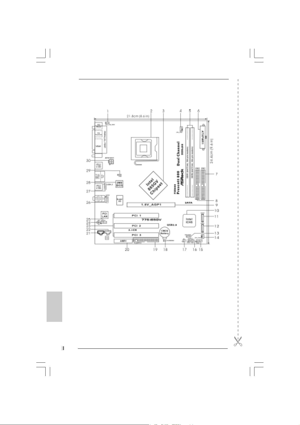
1 PS2_USB_PWR1 Jumper 16 System Panel Hea der (P ANEL1)
2 775-Pin CPU Socket 17 Infrared Module Header (IR1)
3 North Bridge Controller 18 Clear CMOS Jumper (CLRCMOS0)
4 CPU Fan Connector (CPU_FAN1) 19 Floppy Connector (FLOPPY1)
5 184-pin DDR DIMM Slots (DDR1- 2, Dual Channel) 20 AMR Slot (AMR1)
6 A TX Power Connector (ATXPWR1) 21 Internal Audio Connector: CD1 (Black)
7 Primary IDE Connector (IDE1, Blue) 22 Internal Audio Connector: AUX1 (White)
8 Secondary IDE Connector (IDE2, Black) 23 PCI Slots (PCI1- 3)
9 ASRock Graphics Interface Slot (1.5V_AGP1) 24 JR1 Jumper / JL1 Jumper
10 South Bridge Controller 25 Front Panel Audio Header (AUDIO1)
11 Secondary Serial A TA Connector (SA TA2) 26 COM Port Header (COM1)
12 Primary Serial A T A Connector (SATA1) 27 Shared USB 2.0 Header (USB4_5, Blue)
13 Chassis Speaker Header (SPEAKER 1) 2 8 BIOS FWH Chip
14 Chassis Fan Connector (CHA_FAN1) 29 FSB Select Jumper (FSB1)
15 USB 2.0 Header (USB67, Blue) 30 A TX 12V Connector (ATX12V1)
ASRock 775i65GV Motherboard
TMTM
TM
ASRock I/O PlusASRock I/O Plus
ASRock I/O Plus
ASRock I/O PlusASRock I/O Plus
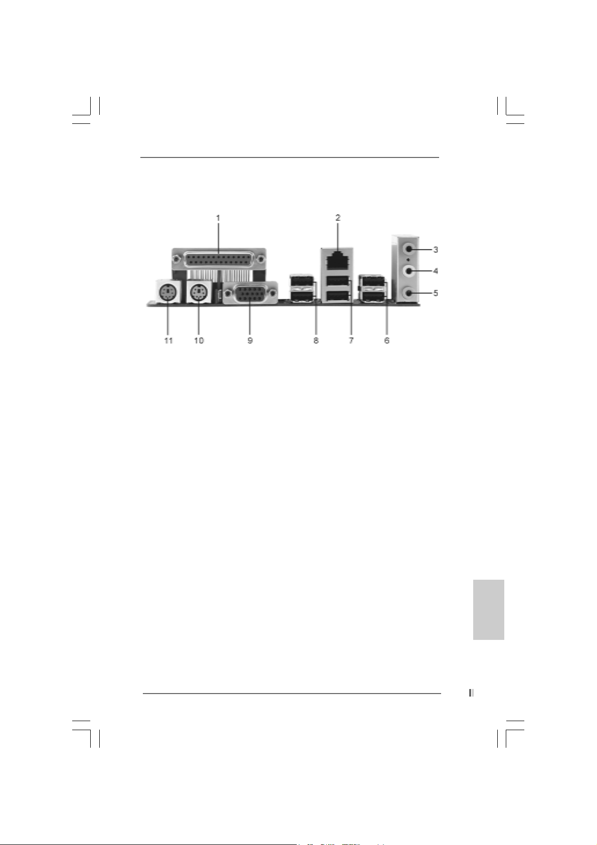
1 Parallel Port 7 USB 2.0 Ports (USB01)
2 RJ-45 Port 8 USB 2.0 Ports (USB23)
3 Line In (Light Blue) 9 VGA Port
4 Line Out (Lime) 10 PS/2 Keyboard Port (Purple)
5 Microphone (Pink) 11 PS/2 Mouse Port (Green)
6 Shared USB 2.0 Ports (USB45)
TMTM
ASRock 775i65GV Motherboard
EnglishEnglish
EnglishEnglish
English
33
3
33
1. Introduction1. Introduction
1. Introduction
1. Introduction1. Introduction
Thank you for purchasing ASRock 775i65GV motherboard, a reliable motherboard
produced under ASRock’s consistently stringent quality control. It delivers excellent
performance with robust design conforming to ASRock’s commitment to quality and
endurance.
This Quick Installation Guide contains introduction of the motherboard and step-bystep installation guide. More detailed information of the motherboard can be found in
the user manual presented in the Support CD.
Because the motherboard specifications and the BIOS software might be
updated, the content of this manual will be subject to change without
notice. In case any modifications of this manual occur, the updated
version will be available on ASRock website without further notice. You
may find the latest memory and CPU support lists on ASRock website as
well. ASRock website
1.1 Package Contents1.1 Package Contents
1.1 Package Contents
1.1 Package Contents1.1 Package Contents
ASRock 775i65GV Motherboard
(Micro ATX Form Factor: 9.6-in x 8.6-in, 24.4 cm x 21.8 cm)
ASRock 775i65GV Quick Installation Guide
ASRock 775i65GV Support CD (including LGA 775 CPU Installation Live Demo)
One 80-conductor Ultra ATA 66/100 IDE Ribbon Cable
One Ribbon Cable for a 3.5-in Floppy Drive
One Serial ATA (SATA) Data Cable
One Serial ATA (SATA) HDD Power Cable (Optional)
One ASRock I/O PlusTM Shield
One COM Port Bracket
One ASRock M R Card (Option al)
http://www.asrock.com
English
EnglishEnglish
EnglishEnglish
44
4
44
ASRock 775i65GV Motherboard

1.2 Specifications1.2 Specifications
1.2 Specifications
1.2 Specifications1.2 Specifications
Platform: Micro ATX Form Factor: 9.6-in x 8.6-in, 24.4 cm x 21.8 cm
CPU: 775-Pin Socket
supporting Intel® Pentium® 4 / Celeron® processor (in 775-land
LGA package)
Chipsets: North Bridge:
Intel® 865GV chipset, FSB @ 800 / 533 MHz,
supports Hyper-Threading Technology (see CAUTION 1)
South Bridge:
Intel® ICH5, supports SATA 1.5Gb/s
Memory: 2 DDR DIMM slots: DDR1 and DDR2
supports PC3200 (DDR400) / PC2700 (DDR333) /
PC2100 (DDR266), Max. 2GB (see CAUTION 2)
Dual Channel Memory Technology support
(see CAUTION 3)
IDE: IDE1: ATA 100 / Ultra DMA Mode 5
IDE2: ATA 100 / Ultra DMA Mode 5
Supports up to 4 IDE devices
Serial ATA: Supports up to 2 SATA devices at 1.5Gb/s data transfer rate.
(No Support for “RAID” and “Hot Plug” functions)
Floppy Port: Supports up to 2 floppy disk drives
Audio: 5.1 channels AC’97 Audio
PCI LAN: Speed: 802.3u (10/100 Ethernet), supports Wake-On-LAN
Hardware Monitor:CPU temperature sensing
Motherboard temperature sensing
CPU overheat shutdown to protect CPU life
(ASRock U-COP)(see CAUTION 4)
CPU fan ta chometer
Chassis fan tachometer
Voltage monitoring: +12V, +5V, +3.3V, Vcore
PCI slots: 3 PCI slots with PCI Specification 2.2 (see CAUTION 5)
AMR slot: 1 slot, supports ASRock MR card (Optional)
AGI slot: 1 AGI [ASRock Graphics Interface] slot (see CAUTION 6)
USB 2.0: 8 USB 2.0 ports:
includes 6 default USB 2.0 ports on the rear panel,
plus one header to support 2 additional USB 2.0 ports
(see CAUTION 7)
ASRock I/O PlusTM: 1 PS/2 mouse port, 1 PS/2 keyboard port,
1 VG A port, 1 parallel port: ECP/EPP support,
6 default USB 2.0 ports,
1 RJ-45 port,
Audio Jack: Line In / Line Out / Microphone
ASRock 775i65GV Motherboard
EnglishEnglish
EnglishEnglish
English
55
5
55
English
EnglishEnglish
EnglishEnglish
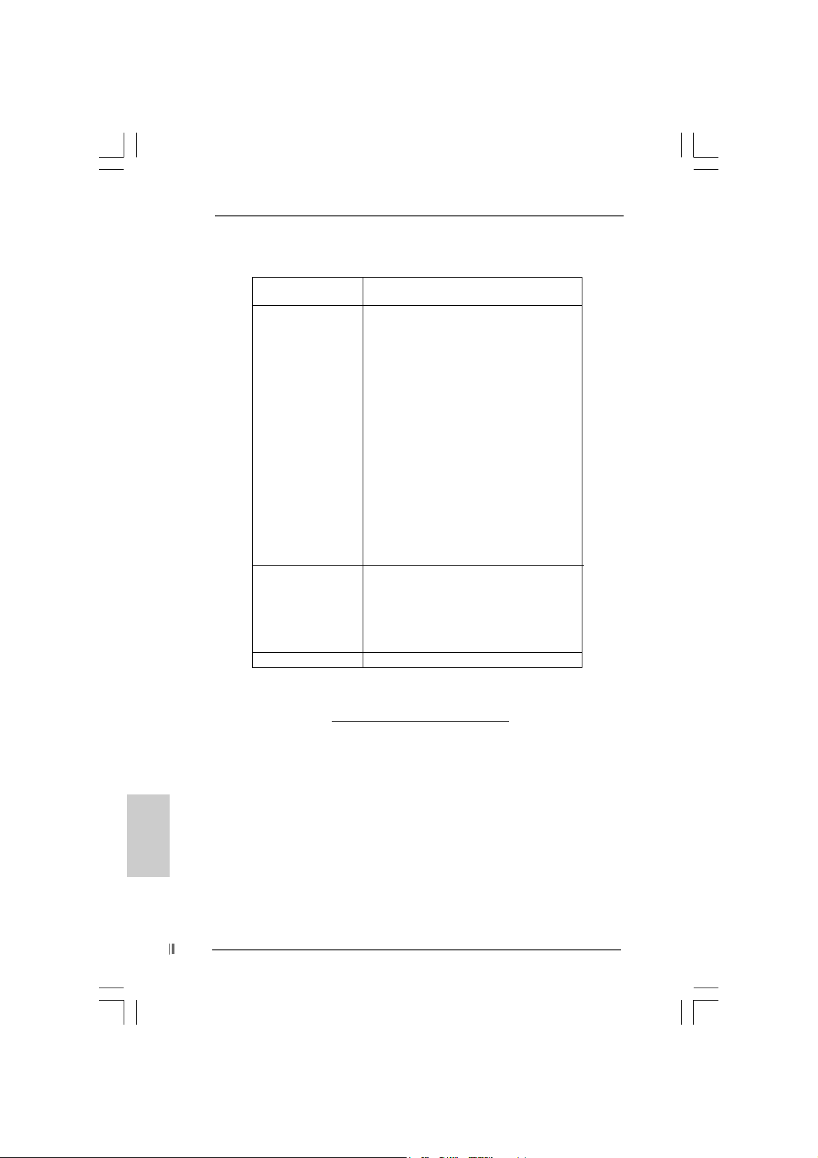
COM Port: 1 COM Port Header to support a COM port module
BIOS: AMI legal BIOS, Supports “Plug and Play”,
ACPI 1.1 compliance wake up events,
CPU frequency stepless control
(only for advanced users’ reference, see CAUTION 8)
OS: Microsoft® Windows® 98 SE / ME / 2000 / XP compliant
CAUTION!
1. About the setting of “Hyper Threading T echnology”, please check page 27
of “User Manual” in the Support CD.
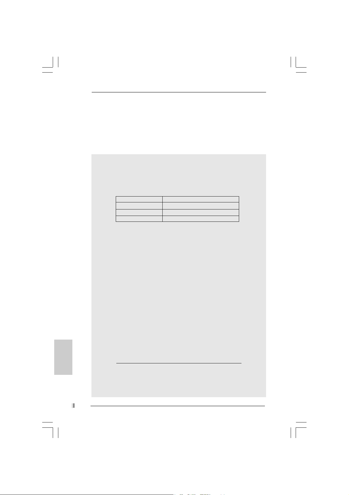
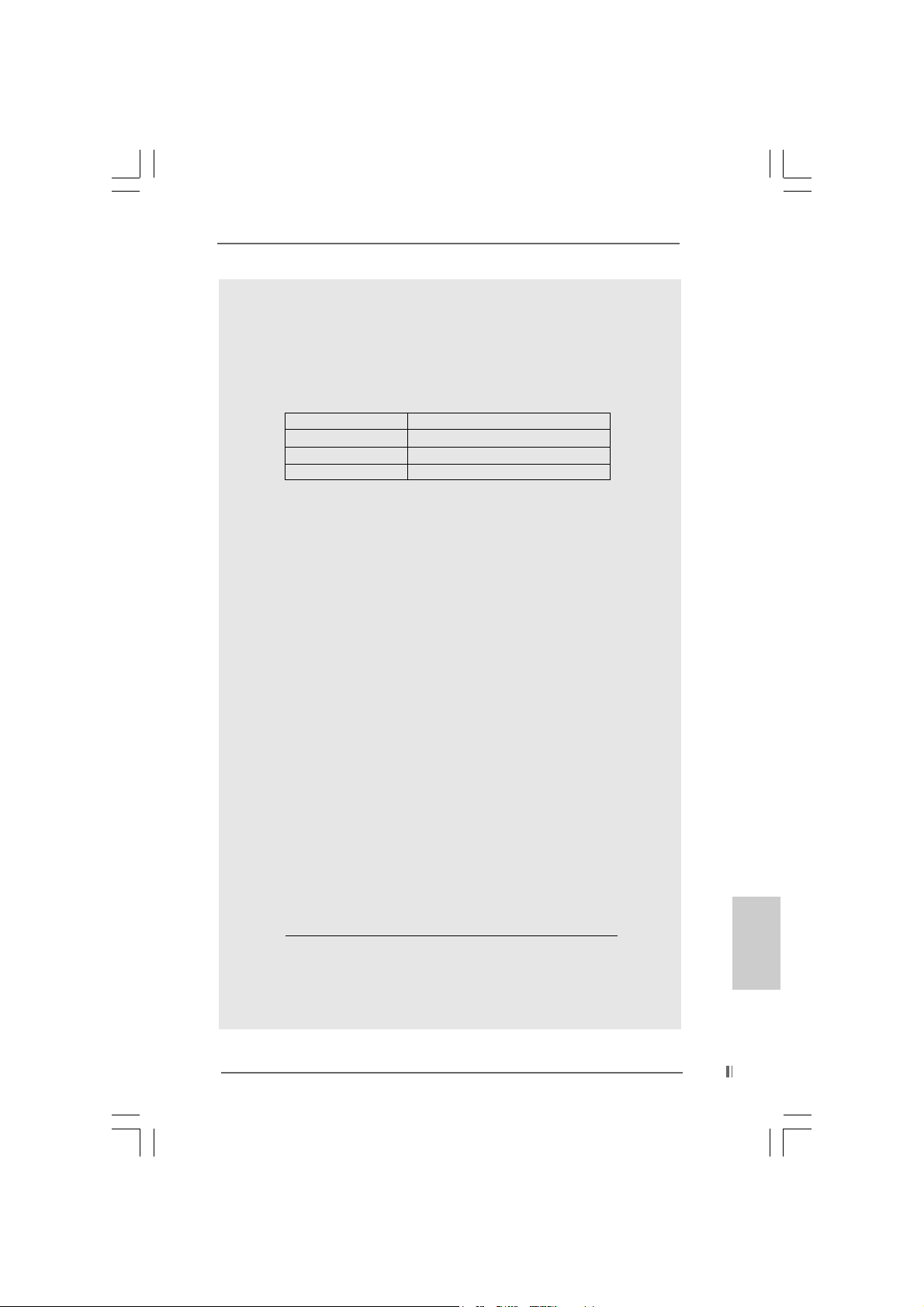
2. Please check the table below for the memory support frequency and its
corresponding CPU FSB frequency.
CPU FSB Frequency Memory Support Frequency
800 DDR266, DDR320
533 DDR266, DDR333
400 DDR266
* When you use an FSB800-CPU on this motherboard, it will run at
DDR320 if you adopt a DDR333 memory module.
3. This motherboard supports Dual Channel Memory Technology . Bef ore you
implement Dual Channel Memory Technology, make sure to read the
installation guide of memory modules on page 12 for proper installation.
4. While CPU overheat is detected, the system will automatically shutdown.
Before you resume the system, please check if the CPU fan on the
motherboard functions properly and unplug the power cord, then plug it
back again. To improve heat dissipation, remember to spray thermal
grease between the CPU a nd the he atsink when you install the PC syste m.
5. Because the installed AMR card will occupy the same external connecting
position with the PCI card that are installed in “PCI3” slot, you will not be
able to install any PCI card in “PCI3” slot if an AMR card has already been
installed in the AMR slot.
6. The AGI [ASRock Graphics Interface] slot is a special design that only
supports compatible AGP VGA cards. For the information of the compatible
AGP VGA cards, please refer to the “Supported AGP VGA Cards List” on
page 7 and page 8. For the proper installation of AGP VGA card, please
refer to the installation guide on page 13.
7. Power Management for USB 2.0 works fine under Microsoft
SP1 / 2000 SP4. It may not work properly under Microsoft® Windows® 98/
ME. Please refer to Microsoft® official document at
http://www.microsoft.com/whdc/hwdev/bus/USB/USB2support.mspx
8. Although this motherboard offers stepless control, it is not recommended
to perform over-clocking. Frequencies other than the recommended CPU
bus frequencies may cause the instability of the system or damage the
CPU.
*, DDR400
®
Windows® XP
66
6
66
ASRock 775i65GV Motherboard

1.31.3
Supported AGP VGA Cards ListSupported AGP VGA Cards List
1.3
Supported AGP VGA Cards List
1.31.3
Supported AGP VGA Cards ListSupported AGP VGA Cards List
(for Windows 2000/Windows XP)
I. AGP 4X
Graphics Chip Model Name
Vendor
n-VIDIA ASUS AGP-V7100
A T I Gigabyte GV-AP64D
SiS SYNNEX GCM-SiS315EA32
ASUS AGP-V7100PRO
ASUS AGP-V7100 MAGIC / 32M
ASUS AGP-V7700Ti
ASUS AGP-V8170DDR
ASUS AGP-V8170SE / LP
ASUS AGP-V8200 T2
ASUS AGP-V8200 T5
ASUS AGP-V8440
ASUS AGP-V8460 Ultra
GAINW ARD- GF3-TI500/64M
GAINW ARD- GF3-TI500/128M
Inno3D GeForce2 MX400
Leadtek WinFa st A170 TH
Leadtek WinFast A170 DDR
Leadtek WinFast A250LE TD
Leadtek WinFa st GeForce2 M X MX64
Leadtek WinFast GeForce2 H MX400
MSI- GF4-MX440SE
PROLINK GF4-MX440
SPARKLE GF4-M X440
Gigabyte GV-AP64D-H
Gigabyte GV-AR64S-H
POWERCOLOR RADEON 9000
POWERCOLOR RADEON 9100
TRANSCEND TS64MVDR7
For the latest updates of the supported AGP VGA cards list, please visit
ASRock website for details.
ASRock website: http://www.asrock.com/support/index.htm
ASRock 775i65GV Motherboard
EnglishEnglish
EnglishEnglish
English
77
7
77
II. AGP 8X
Graphics Chip Model Name
Vendor
n-VIDIA ALBATRON GF4-M X440 64M
AOPEN Aeolus FX5600S-DV128
AOPEN Aeolus FX5200-V128
ASUS AGP-V9180
ASUS AGP-V9280 VIEDO SUITE
ASUS AGP-V9520 MAGIC/T
ASUS V9900
ASUS V9900 ULTRA
ELSA-GLADIC 518
ELSA-GLADIC 518 P
Inno3D GeForce FX5600
LEADTEK A280 LE
LEADTEK A340TDH
MSI Ti4800SE-VT D8X
PALIT GF4 M X440 8X 64MB
PROLINK GeForceFX5900
PROLINK GF4-TI4200
SPARKLE GF4-M X440-8X
A T I CLUB3D ATI R9800
Gigabyte GV R9000 PRO
Gigabyte RADEON 9500
Gigabyte RADEON 9700 PRO
POWER COLOR 9200
SAPHIRE RADEON 9200-128MB
SiS POWER COLOR XABRE600
English
EnglishEnglish
EnglishEnglish
88
8
88
For the latest updates of the supported AGP VGA cards list, please visit
ASRock website for details.
ASRock website:
http://www.asrock.com/support/index.htm
ASRock 775i65GV Motherboard
2.2.
InstallationInstallation
2.
Installation
2.2.
InstallationInstallation
Pre-installation PrecautionsPre-installation Precautions
Pre-installation Precautions
Pre-installation PrecautionsPre-installation Precautions
Take note of the following precautions before you install motherboard components or change any motherboard settings.
1. Unplug the power cord from the wall socket before touching any
component. Failure to do so may cause severe damage to the
motherboard, peripherals, and/or components.
2. To avoid damaging the motherboard components due to static
electricity, NEVER place your motherboard directly on the carpet
or the like. Also remember to use a grounded wrist strap or touch
a safety grounded object before you handle components.
3. Hold components by the edges and do not touch the ICs.
4. Whenever you uninstall any component, place it on a grounded
antstatic pad or in the bag that comes with the component.
5. When placing screws into the screw holes to secure the
motherboard to the chassis, please do not over-tighten the
screws! Doing so may damage the motherboard.
2.12.1
CPU InstallationCPU Installation
2.1
CPU Installation
2.12.1
CPU InstallationCPU Installation
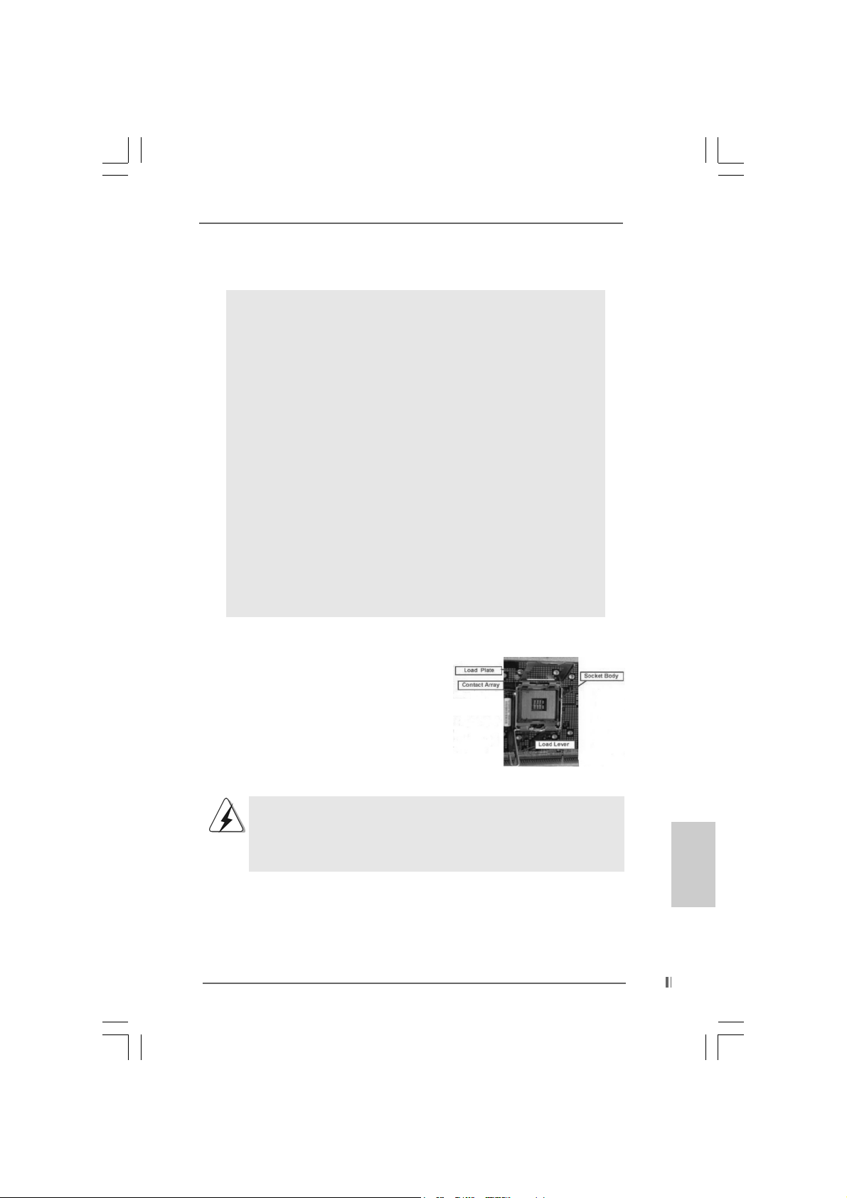
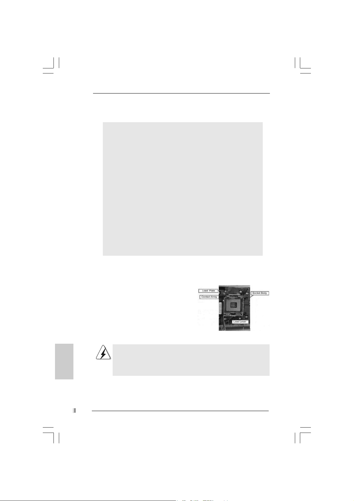
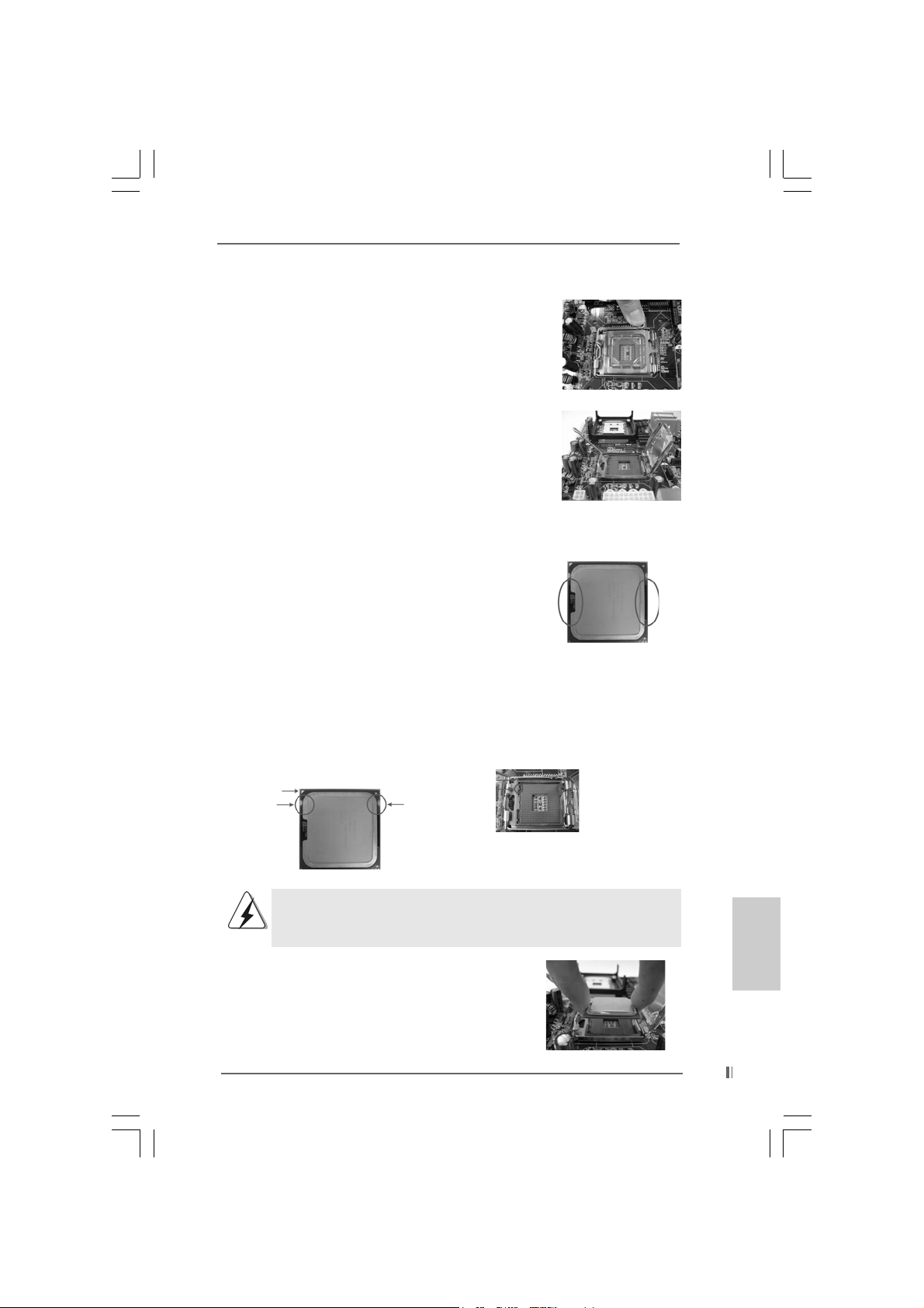
For the installation of Intel 775-Pin CPU,
please follow the steps below.
775-Pin Socket Overview
Before you insert the 775-Pin CPU into the socket, please check if the
CPU surface is unclean or if there is any bent pin on the socket. Do
not force to insert the CPU into the socket if above situation is found.
Otherwise, the CPU will be seriously damaged.
ASRock 775i65GV Motherboard
EnglishEnglish
EnglishEnglish
English
99
9
99
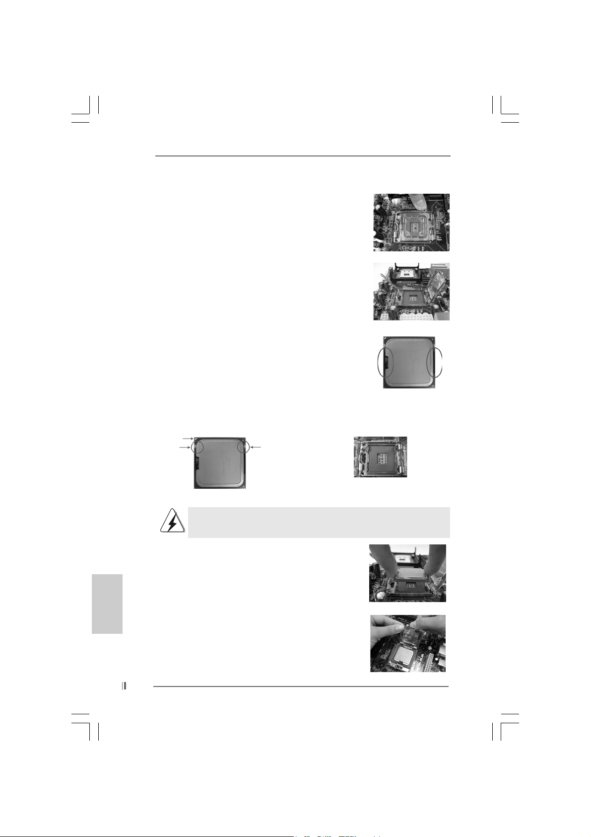
Step 1. Open the socket:
Step 1-1. Disengaging the lever by depressing
down and out on the hook to clear
retention tab.
Step 1-2. Rotate the load lever to fully open po-
sition at approximately 135 degrees.
Step 1-3. Rotate the load plate to fully open po-
sition at approximately 100 degrees.
Step 2. Insert the 775-Pin CPU:
Step 2-1. Hold the CPU by the edges where are
marked with black lines.
Step 2-2. Orient the CPU with IHS (Integrated
Heat Sink) up. Locate Pin1 and the two
orientation key notches.
Pin1
orientation
key notch
orientation
key notch
Pin1
alignment key
black line
black line
alignment key
English
EnglishEnglish
EnglishEnglish
1010
10
1010
775-Pin Socket
775-Pin CPU
For proper inserting, please ensure to match the two orientation key
notches of the CPU with the two alignment keys of the socket.
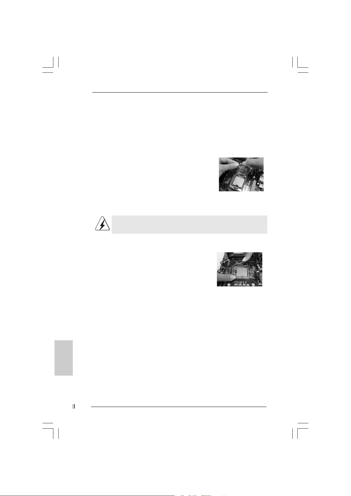
Step 2-3. Carefully place the CPU into the socket
by using a purely vertical motion.
Step 2-4. Verify that the CPU is within the socket
and properly mated to the orient keys.
Step 3. Remove PnP Cap (Pick and Pla ce Cap):
Use your left hand index finger and thumb to
support the load plate edge, engage PnP cap
with right hand thumb and peel the cap from the
socket while pressing on center of PnP cap to
assist in removal.
ASRock 775i65GV Motherboard
It is recommended to use the cap tab to handle and avoid kicking off
the PnP cap.
Step 4. Close the socket:
Step 4-1. Rotate the load plate onto the IHS.
Step 4-2. While pressing down lightly on load
plate, engage the load lever.
Step 4-3. Secure load lever with load plate tab
under retention tab of load lever.
2.22.2
Installation of CPU Fan and HeatsinkInstallation of CPU Fan and Heatsink
2.2
Installation of CPU Fan and Heatsink
2.22.2
Installation of CPU Fan and HeatsinkInstallation of CPU Fan and Heatsink
For proper installation, please kindly refer to the instruction manuals of
your CPU fan and heatsink.
Below is an example to illustrate the installation of the heatsink for 775-Pin CPU.
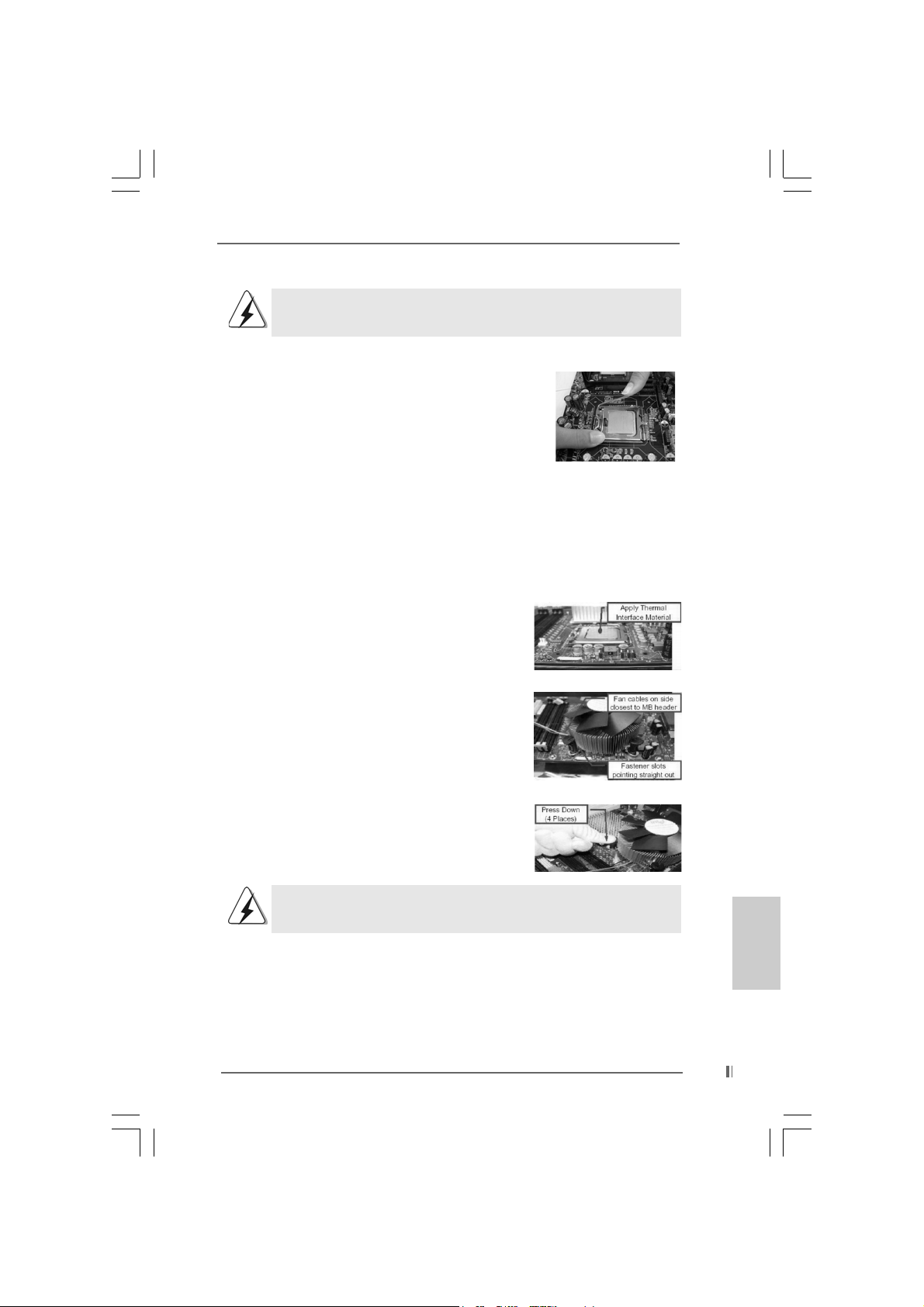
Step 1. Apply thermal interface material onto center
of IHS on the socket surface.
Step 2. Place the heatsink onto the socket. Ensure
fan cables are oriented on side closest to the
CPU fan connector on the motherboard
(CPU_FAN1, see page 10, No. 4).
Step 3. Align fasteners with the motherboard
throughholes.
Step 4. Rotate the fastener clockwise, then press
down on fastener caps with thumb to install
and lock. Repeat with remaining fasteners.
If you press down the fasteners without rotating them clockwise,
the heatsink cannot be secured on the motherboard.
Step 5. Connect fan header with the CPU fan
connector on the motherboard.
Step 6. Secure excess cable with tie-wrap to ensure
cable does not interfere with fan operation or
contact other components.
ASRock 775i65GV Motherboard
1111
11
1111
EnglishEnglish
EnglishEnglish
English
2.32.3
Installation of Memory Modules (DIMM)Installation of Memory Modules (DIMM)
2.3
Installation of Memory Modules (DIMM)
2.32.3
Installation of Memory Modules (DIMM)Installation of Memory Modules (DIMM)
775i65GV motherboard provides two 184-pin DDR (Double Data Rate) DIMM slots,
and supports Dual Channel Memory Technology. For dual channel configuration,
you always need to install two identical (the same brand, speed, size and chiptype) memory modules in the DDR DIMM slots to activate Dual Channel Memory
Technology. Otherwise, it will operate at single channel mode.
If you install only one memory module or two non-identical memory
modules, it is unable to activate the Dual Channel Memory Technology.
Installing a DIMMInstalling a DIMM
Installing a DIMM
Installing a DIMMInstalling a DIMM
Please make sure to disconnect power supply before adding or
removing DIMMs or the system components.
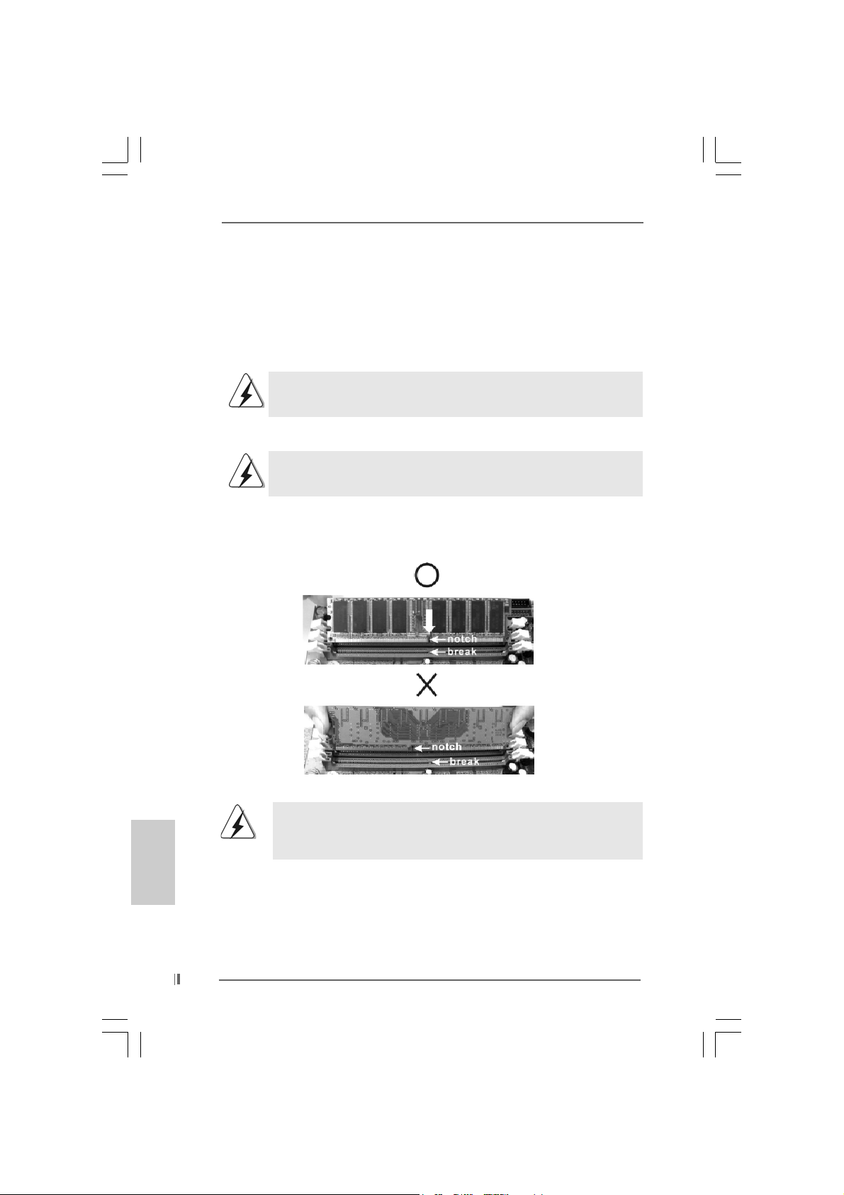
Step 1. Unlock a DIMM slot by pressing the retaining clips outward.
Step 2. Align a DIMM on the slot such that the notch on the DIMM matche s the brea k
on the slot.
English
EnglishEnglish
EnglishEnglish
1212
12
1212
The DIMM only fits in one correct orientation. It will cause permanent
damage to the motherboard and the DIMM if you force the DIMM into
the slot at incorrect orientation.
Step 3. Firmly insert the DIMM into the slot until the retaining clips at both ends fully
snap back in place and the DIMM is properly seated.
ASRock 775i65GV Motherboard
2.4 Expansion Slots (PCI, AMR, and AGI Slots)2.4 Expansion Slots (PCI, AMR, and AGI Slots)
2.4 Expansion Slots (PCI, AMR, and AGI Slots)
2.4 Expansion Slots (PCI, AMR, and AGI Slots)2.4 Expansion Slots (PCI, AMR, and AGI Slots)
There are 3 PCI slots, 1 AMR slot, and 1 AGI slot on this motherboard.
PCI slots: PCI slots are used to install expansion cards that have the 32-bit PCI
interface.
Because the installed AMR card will occupy the same external
connecting position with the PCI card installed in “PCI3” slot, you will
no be able to install any PCI card in “PCI3” slot if an AMR card has
already been installed in the AMR slot.
AMR slot: AMR slot is used to insert an ASRock MR card (optional) with v.92
Modem functionality.
AGI slot: The AGI [ASRock Graphics Interface] slot is a special design that only
supports compatible AGP VGA cards. For the information of the compatible AGP VGA cards, please refer to the “Supported AGP VGA Cards List”
on page 7 and page 8.
To install the system with an add-on AGP VGA card, you must make
sure to install the driver of add-on AGP VGA card before you install
the onboard VGA driver. If the onboard VGA driver has already been
installed before you install the add-on AGP VGA card, the system will
automatically set the onboard V GA as the primary graphics adapter. In
that case, if you want to install the add-on AGP VGA card, you need
to remove the onboard VGA driver first, and then install the add-on
AGP VGA card and its driver. For the detailed instruction, plea se refer
to the documents in the Support CD, “AGI Slot Installation Guide (for
Windows 2000)” and “AGI Slot Installation Guide (for Windows XP)”,
which are located in the folder at the following path:
..\ Easy Dual Monitor
Installing an expansion cardInstalling an expansion card
Installing an expansion card
Installing an expansion cardInstalling an expansion card
Step 1. Before installing the expansion card, please make sure that the power
supply is switched off or the power cord is unplugged. Please read the
documentation of the expansion card and make necessary hardware
settings for the card before you start the installation.
Step 2. Remove the bracket facing the slot that you intend to use. Keep the screws
for later use.
Step 3. Align the card connector with the slot and press firmly until the card is
completely seated on the slot.
Step 4. Fasten the card to the chassis with screws.
ASRock 775i65GV Motherboard
1313
13
1313
EnglishEnglish
EnglishEnglish
English
2.5 Easy Dual Monitor Feature2.5 Easy Dual Monitor Feature
2.5 Easy Dual Monitor Feature
2.5 Easy Dual Monitor Feature2.5 Easy Dual Monitor Feature
Thanks to ASRock patented AGI8X Technology, this motherboard supports Easy
Dual Monitor upgrade. With the internal onboard VGA and the external add-on AGP
VGA card, you can easily enjoy the benefits of Dual Monitor feature. For the
detailed instruction, please refer to the document at the following path in the
Support CD: ..\ Easy Dual Monitor
2.6 Jumpers Setup2.6 Jumpers Setup
2.6 Jumpers Setup
2.6 Jumpers Setup2.6 Jumpers Setup
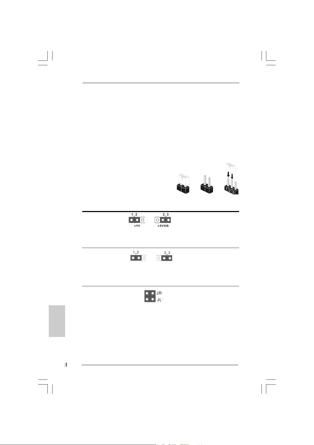
The illustration shows how jumpers are
setup. When the jumper cap is placed on
pins, the jumper is “SHORT”. If no jumper ca p
is placed on the pins, the jumper is “OPEN”.
The illustration shows a 3-pin jumper whose
pin1 and pin2 are “SHORT” when jumper cap
is placed on these 2 pins.
Jumper Setting Description
PS2_USB_PWR1 Short pin2, pin3 to enable
(see p.2 No. 1) +5VSB (standby) for PS/2
Note: To select +5VSB, it requires 2 Amp and higher standby current provided by
power supply.
Short Open
or USB wake up events.
English
EnglishEnglish
EnglishEnglish
1414
14
1414
FSB Select Jumper
(see p.2 No. 29)
Note: The default setting of the FSB Select jumper is “NORMAL” (short pin1, pin2).
For the system’s stability, please keep the default setting.
JR1 / JL1 Jumpers
(see p.2 No. 24)
Note:If JR1 and JL1 Jumpers are short, both the front panel and the rear panel
audio connectors can work.
NORMAL
ASRock 775i65GV Motherboard
TEST
Clear CMOS
(CLRCMOS0)
(see p.2 No. 18)
Note:CLRCMOS0 allows you to clear the data in CMOS. The data in CMOS includes
system setup information such as system password, date, time, and system
setup parameters. To clear and reset the system parameters to default setup,
please turn off the computer and unplug the power cord from the power
supply. After waiting for 15 seconds, use a jumper cap to short the Clear CMOS
jumper for 5 seconds. After shorting the Clear CMOS jumper, please remove
the jumper cap. However, please do not clear the CMOS right after you update
the BIOS. If you need to clear the CMOS when you just finish updating the BIOS,
you must boot up the system first, and then shut it down before you do the
clear-CMOS action.
2-pin jumper
ASRock 775i65GV Motherboard
1515
15
1515
EnglishEnglish
EnglishEnglish
English
2.7 Onboard Headers and Connectors2.7 Onboard Headers and Connectors
2.7 Onboard Headers and Connectors
2.7 Onboard Headers and Connectors2.7 Onboard Headers and Connectors
Onboard headers and connectors are NOT jumpers. Do NOT place
jumper caps over these headers and connectors. Placing jumper caps
over the headers and connectors will cause permanent damage of the
motherboard!
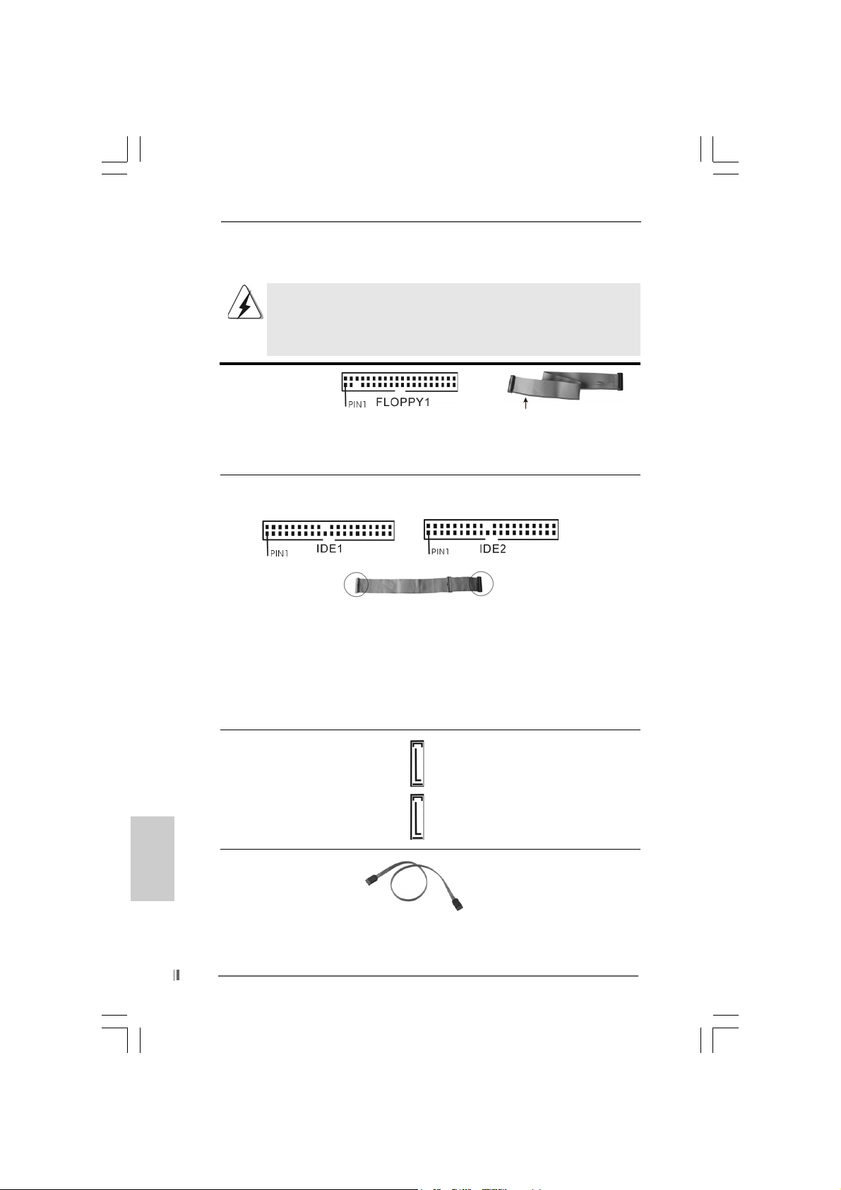
FDD connector
(33-pin FLOPPY1)
(see p.2 No. 19)
the red-striped side to Pin1
Note: Make sure the red-striped side of the cable is plugged into Pin1 side of the
connector.
Primary IDE connector (Blue) Secondary IDE connector (Black)
(39-pin IDE1, see p.2 No. 7) (39-pin IDE2, see p.2 No. 8)
English
EnglishEnglish
EnglishEnglish
1616
16
1616
connect the blue end
to the motherboard
connect the black end
to the IDE devices
80-Conductor ATA 66/100 cable
Note: If you use only one IDE device on this motherboard, please set the IDE
device as “Master”. Please refer to the instruction of your IDE device vendor
for the details. Besides, to optimize compatibility and performance, please
connect your hard disk drive to the primary IDE connector (IDE1, blue) and
CD-ROM to the secondary IDE connector (IDE2, black).
Serial ATA Connectors These two Serial ATA (SATA)
(SAT A1: see p.2 No. 12) connectors support SATA data
(SAT A2: see p.2 No. 1 1) cables for internal storage
SAT A2
SAT A1
devices. The current SATA
interface allows up to 1.5 Gb/s
data transfer rate.
Serial A TA (SATA) Either end of the SATA data ca ble
Data Cable can be connected to the SATA
hard disk or the SA TA conne ctor
on the motherboard.
ASRock 775i65GV Motherboard
Serial ATA (SATA) Please connect the black end of
Power Cable SATA power cable to the power
(Optional) connector on each drive. Then
connect to the SAT A
HDD power connector
connect to the
power supply
connect the white end of SATA
power cable to the power
connector of the power supply.
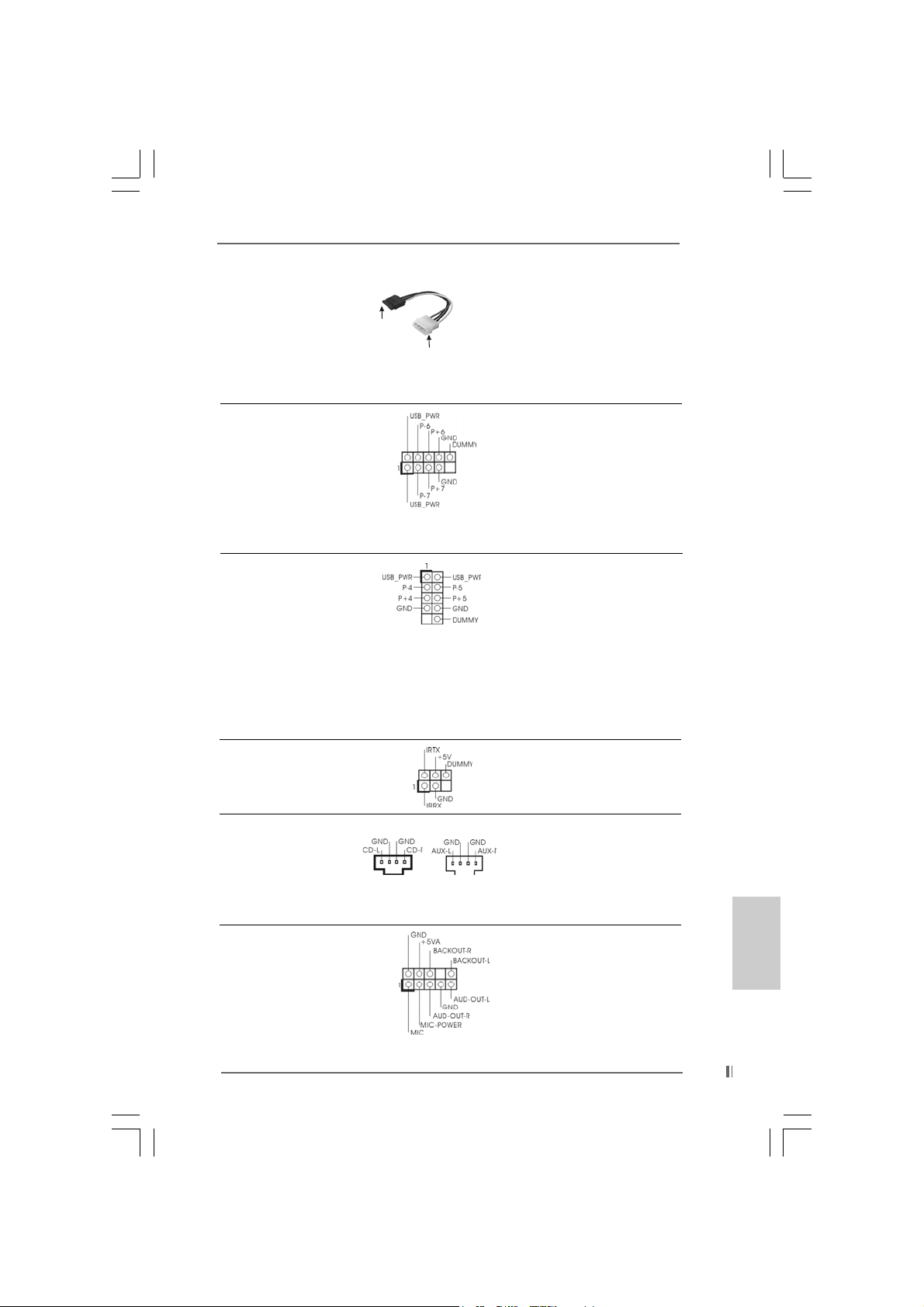
USB 2.0 Header ASRock I/O PlusTM accommo-
(9-pin USB67) dates 6 default USB 2.0 ports. If
(see p.2 No. 15) those USB 2.0 ports on the I/O
panel are not sufficient, this
USB 2.0 header is available to
support 2 additional USB 2.0
ports.
Shared USB 2.0 Header This USB4_5 co nnector is shared
(9-pin USB4_5) with the USB 2.0 ports 4,5 on
(see p.2 No. 27) ASRock I/O Plus
TM
. When using
the front panel USB ports by
attaching the front panel USB
cable to this connector
(USB4_5), the USB ports 4,5 on
ASRock I/O PlusTM will not be able
to function.
Infrared Module Header This header supports an
(5-pin IR1) optional wireless transmitting
(see p.2 No. 17) and receiving infrared module.
Internal Audio Connectors These connectors allow you
(4-pin CD1, 4-pin AUX1) to receive stereo audio input
(CD1: see p.2 No. 21) from sound sources such as
(AUX1: see p.2 No. 22) a CD-ROM, D VD-ROM, TV
CD1 AUX1
tuner card, or MPEG card.
Front Panel Audio Header This is an interface for front
(9-pin AUDIO1) panel audio cable that allows
(see p.2 No. 25) convenient connection and
control of audio devices.
ASRock 775i65GV Motherboard
1717
17
1717
EnglishEnglish
EnglishEnglish
English
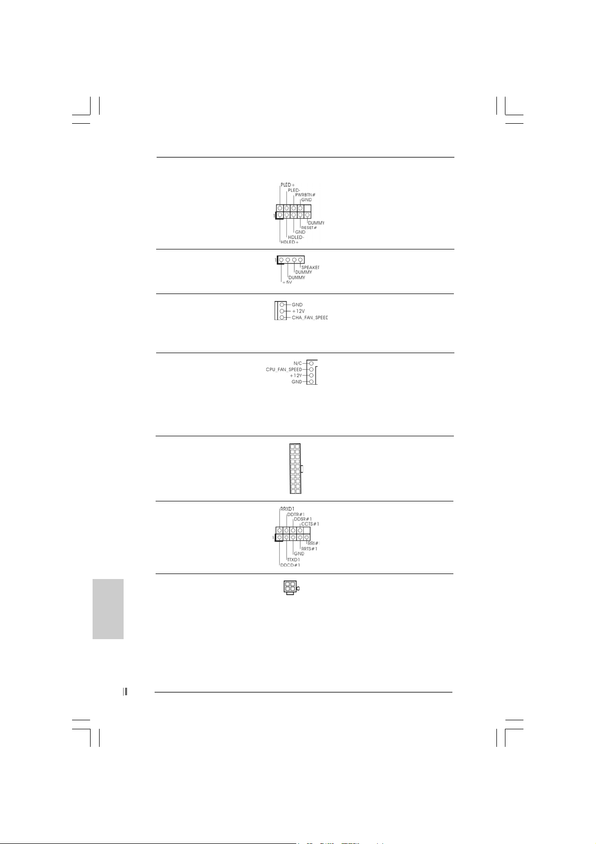
System Panel Header This header accommodates
(9-pin PANEL1) several system front panel
(see p.2 No. 16) functions.
Chassis Speaker Header Please connect the chassis
(4-pin SPEAKER 1) speaker to this header.
(see p.2 No. 13)
Chassis Fan Connector Please connect a chassis fan
(3-pin CHA_FAN1) cable to this connector and
(see p.2 No. 14) match the black wire to the
ground pin.
CPU Fan Connector You may connect either a 3-pin
(4-pin CPU_FAN1) or a 4-pin CPU fan cable to this
(see p.2 No. 4) connector, then match the black
wire to the ground pin.
Note: If you use a 3-pin CPU fan cable, insert it to the connector by aligning it with the pins
“GND”, “+12V”, and “CPU_FAN_SPEED”.
ATX Power Connector Please connect an ATX power
(20-pin ATXPW R1) supply to this connector.
(see p.2 No. 7)
English
EnglishEnglish
EnglishEnglish
1818
18
1818
COM Port Header This COM port header is used
(9-pin COM1) to support a COM port module.
(see p.2 No. 23)
ATX 12V Connector Please note that it is necessary
(4-pin A TX12V1) to connect a power supply with
(see p.2 No. 30) ATX 12V plug to this connector
so that it can provides sufficient
power. Failing to do so will cause
the failure to power up.
ASRock 775i65GV Motherboard
2.82.8
Serial ASerial A
2.8
Serial A
2.82.8
Serial ASerial A
This motherboard adopts Intel ICH5 south bridge chipset that supports Serial ATA
(SATA) hard disks. You may install SATA hard disks on this motherboard for
internal storage devices. This section will guide you to install the SATA hard disks.
STEP 1: Install the SATA hard disks into the drive bays of your chassis.
STEP 2: Connect the SATA power cable to the SATA hard disk.
STEP 3: Connect one end of the SATA data cable to the motherboard’s SATA
connector.
STEP 4: Connect the other end of the SATA data cable to the SATA hard disk.
3. BIOS Information3. BIOS Information
3. BIOS Information
3. BIOS Information3. BIOS Information
The BIOS Setup Utility is stored in the BIOS FWH chip. When you start up the
computer, please press <F2> during the Power-On-Self-Test (POST) to enter the
BIOS Setup Utility; otherwise, POST continues with its test routines. If you wish to
enter the BIOS Setup Utility after POST, please resume the system by pressing <Ctl>
+ <Alt> + <Delete>, or pressing the reset button on the system chassis. For the
detailed information about the BIOS Setup Utility, please refer to the User Manual
(PDF file) contained in the Support CD.
TT
A (SAA (SA
TT
T
TT
Before you install OS into the SATA hard disk, you need to check and
ensure the configuration of the OnBoard IDE Operate Mode option in
BIOS setup is correct according to the condition of your system. For
the configuration details, please refer to the instruction on page 27 of
“User Manual” in the Support CD.
A) Hard Disks InstallationA) Hard Disks Installation
A (SA
T
A) Hard Disks Installation
A (SAA (SA
TT
A) Hard Disks InstallationA) Hard Disks Installation
ASRock 775i65GV Motherboard
1919
19
1919
EnglishEnglish
EnglishEnglish
English

4. Software Suppor4. Software Suppor
4. Software Suppor
4. Software Suppor4. Software Suppor
This motherboard supports various Microsoft® Windows® operating systems: 98 SE/
ME / 2000 / XP. The Support CD that came with the motherboard contains necessary
drivers and useful utilities that will enhance motherboard features.
To begin using the Support CD, insert the CD into your CD-ROM drive. It will display
the Main Menu automatically if “AUTORUN” is enabled in your computer. If the Main
Menu does not appear automatically, locate and double-click on the file
“ASSETUP.EXE” from the “BIN” folder in the Support CD to display the menus.
“PC-DIY Live Demo”
ASRock presents you a multimedia PC-DIY live demo, which shows you a
step-by-step guide to install your own PC system. To see this demo program,
you can run Microsoft® Media Player® to play the file, which can be found
through the following path:
..\ MPEGAV \ AVSEQ01.DAT
“LGA 775 CPU Installation Live Demo”
This motherboard is equipped with Intel LGA 775 socket, which is a new CPU
socket interface that Intel has released. Since it has several tiny pins, whcih
are easily to be damaged by improper handling, ASRock sincerely presents
you a clear installation guide through this “LGA 775 CPU Installation Live
Demo”. We hope you may check this live demo program before you start the
installation of LGA 775 CPU in order to reduce the risks of CPU and
motherboard damages caused by any improper handling. To see this Live
Demo, you can run Microsoft® Media Player® to play the file. You may find this
Live Demo in the motherboard’s Support CD through the following path:
..\ MPEGAV \ LGA775INST.DAT
t CD informationt CD information
t CD information
t CD informationt CD information
English
EnglishEnglish
EnglishEnglish
2020
20
2020
ASRock 775i65GV Motherboard
1. Einführung1. Einführung
1. Einführung
1. Einführung1. Einführung
Wir danken Ihnen für den Kauf des ASRock 775i65GV Motherboard, ein zuverlässiges
Produkt, welches unter den ständigen, strengen Qualitätskontrollen von ASRock
gefertigt wurde. Es bietet Ihnen exzellente Leistung und robustes Design, gemäß der
Verpflichtung von ASRock zu Qualität und Halbarkeit.
Diese Schnellinstallationsanleitung führt in das Motherboard und die schrittweise
Installation ein. Details über das Motherboard finden Sie in der
Bedienungsanleitung auf der Support-CD.
Da sich Motherboard-Spezifikationen und BIOS-Software verändern können,
kann der Inhalt dieses Handbuches ebenfalls jederzeit geändert werden. Für
den Fall, dass sich Änderungen an diesem Handbuch ergeben, wird eine neue
Version auf der ASRock-Website, ohne weitere Ankündigung, verfügbar sein.
Die jeweils neueste Liste der unterstützten Speichertypen CPUs finden Sie
ebenfalls auf der Webseite von ASRock.
ASRock-Website: http://www.asrock.com
1.1 Kartoninhalt
ASRock 775i65GV Motherboard
(Micro ATX-Formfaktor: 24.4 cm x 21.8 cm; 9.6 Zoll x 8.6 Zoll)
ASRock 775i65GV Schnellinstallationsanleitung
ASRock 775i65GV Support-CD (einschl. LGA 775 CPU Installation Live-Demo)
Ein 80-adriges Ultra-ATA 66/100 IDE-Flachba ndk abel
Ein Flachbandkabel für ein 3,5-Zoll-Diskettenlaufwerk
Ein Seriell-ATA- (SATA) Datenkabel
Ein Seriell-ATA (SATA) Festplattennetzkabel (Option)
Ein ASRock I/O Plus
Ein COM Port-Anschlusshalter
Ein ASRock MR-Karte (Option)
TM
Shield
1.2 Spezifikationen1.2 Spezifikationen
1.2 Spezifikationen
1.2 Spezifikationen1.2 Spezifikationen
Plattform: Micro ATX-Formfaktor: 24.4 cm x 21.8 cm; 9.6 Zoll x 8.6 Zoll
CPU: Unterstützt 775-Pin Socket für Intel Pentium 4 / Celeron
Prozessor (in 775-land LGA Paket)
Chipsatz: North Bridge:
Intel® 865GV-Chipsatz, FSB @ 800 / 533 MHz,
unterstützt Hyper-Threading Technology
(siehe VORSICHT 1)
South Bridge:
Intel® ICH5, unterstützt SATA 1.5Gb/s
ASRock 775i65GV Motherboard
2121
21
2121
DeutschDeutsch
DeutschDeutsch
Deutsch

Deutsch
DeutschDeutsch
DeutschDeutsch
RAM: 2 DDR Slots: DIMM1 und DIMM2
Unterstützt PC3200 (DDR400) /PC2700 (DD R333) /
PC2100 (DDR266), Max. 2GB (siehe VORSICHT 2)
Unterstützung von Dual-Kanal-Speichertechnologi
(siehe VORSICHT 3)
HDD: IDE1: ATA 100 / Ultra DMA Mode 5
IDE2: ATA 100 / Ultra DMA Mode 5
Unterstützt bis 4 IDE-Geräte
Seriell-ATA: 2 SATA-Anschlüsse, unterstützt bis 1.5 Gb/s
Datenübertragungsrate
(Unterstützt keine “RAID”- und “Hot-Plug”-Funktionen)
FDD: Unterstützt bis 2 Diskettenlaufwerke
Audio: 5.1 Kanal AC’97 Audio
PCI LAN: Speed: 802.3u (10/100 Ethernet), unterstützt Wake-On-LAN
Hardware Monitor: CPU Temperaturmessung,
Motherboardtemperaturerkennung,
CPU Shutdown bei Überhitzung, schützt die CPU vor dem
Hitzetod (ASRock U-COP)(siehe VORSICHT 4),
Rotationskontrolle für CPU-Lüfter,
Rotationskontrolle für Gehäuse-Lüfter,
Spannungsüberwachung: +12V, +5V, +3.3V, Vcore
PCI-Slots: 3 Slots nach PCI-Spezifikation 2.2 (siehe VORSICHT 5)
AMR-Slot: Unterstützt ASRock MR-Karten (Option)
AGI-Slot: 1x AGI-Slot [ASRock Graphics Interface] (siehe VORSICHT 6)
USB 2.0: 8 USB 2.0-Anschlüsse:
einschließlich 6 Standard-USB 2.0-Anschlüsse auf der
Rückseite, plus einem Header zur Unterstützung 2
zusätzlicher USB 2.0-Anschlüsse (siehe VORSICHT 7)
ASRock I/O PlusTM: 1 PS/2-Mausanschluss, 1 PS/2-Tastaturanschluss,
1 VGA Port, 1 paralleler port: Unterstützung für ECP / EPP,
6 hintere USB 2.0-Ports, 1 RJ 45 port,
Audioanschlüsse: Line In / Line Out / Mikrofon
COM-Anschluss: 1 COM-Anschluss-Header für ein COM-Anschlussmodul
BIOS: AMI legal BIOS mit Unterstützung für “Plug and Play”,
ACPI 1.1-Weckfunktionen,
Schrittloser CPU-Frequenz-Kontrolle (Nur für erfahrene
Anwender empfohlen, siehe VORSICHT 8)
Betriebssysteme: Unterstützt Microsoft® Windows® 98SE / ME / 2000 / XP
2222
22
2222
ASRock 775i65GV Motherboard
VORSICHT!
1. Die Einstellung der “Hyper-Threading Technology”, finden Sie auf Seite
27 des auf der Support-CD enthaltenen Benutzerhandbuches
beschrieben.
2. Die unterstützten Arbeitsspeicherfrequenzen und die entsprechende
CPU FSB-Frequenz entnehmen Sie bitte der nachstehenden Tabelle.
CPU FSB-Frequenz Unterstützte Arbeitsspeicherfrequenz
800 DDR266, DDR320
533 DDR266, DDR333
400 DDR266
* Bei Verwendung einer FSB800-CPU auf diesem Motherboard läuft es mit
DDR320, wenn Sie ein DDR333-Speichermodul verwenden.
3. Dieses Motherboard unterstützt Dual-Kanal-Speichertechnologie. Vor
Implementierung der Dual-Kanal-Speichertechnologie müssen Sie die
Installationsanleitung für die Speichermodule auf Seite 28 zwecks richtiger
Installation gelesen haben.
4. Wird eine Überhitzung der CPU registriert, führt das System einen
automatischen Shutdown durch. Bevor Sie das System neu starten, prüfen
Sie bitte, ob der CPU-Lüfter am Motherboard richtig funktioniert, und
stecken Sie bitte den Stromkabelstecker aus und dann wieder ein. Um die
Wärmeableitung zu verbessern, bitte nicht vergessen, etwa s Wärmeleitpa ste
zwischen CPU und Kühlkörper zu sprühen.
5. Da die installierte AMR-Karte die gleiche externe Anschlussposition wie
die im “PCI3”-Steckplatz installierte PCI-Karte belegt, können Sie keine
PCI-Karte im “PCI3”-Steckplatz installieren, wenn bereits eine AMRKarte im AMR-Steckplatz installiert ist.
6. Der AGI- [ASRock Graphics Interface] Steckplatz ist so ausgelegt, dass
nur kompatible AGP-Grafikkarten unterstützt werden. Informationen über
kompatible AGP VGA-Karten finden Sie in der “Liste unterstützter AGP
VGA-Karten” auf den Seiten 7 und 8. (Nur Englisch) Die richtige
Installation der AGP-Grafikkarte ist in der Installationsanleitung auf
Seite 29 angegeben.
7. Das Power Management für USB 2.0 arbeitet unter Microsoft
XP SP1/2000 SP4 einwandfrei. Unter Microsoft® Windows® 98/ME
könnte es dagegen zu Störungen kommen. Bitte lessen Sie hierzu das
offizielle Microsoft-Dokument, welches Sie unter folgender Adresse
finden:
http://www.microsoft.com/whdc/hwdev/bus/USB/USB2support.mspx
8. Obwohl dieses Motherboard stufenlose Steuerung bietet, wird Overclocking nicht empfohlen. Frequenzen, die über den für den jeweiligen
Prozessor vorgesehenen liegen, können das System instabil werden
lassen oder die CPU beschädigen.
*, DDR400
®
Windows
®
DeutschDeutsch
DeutschDeutsch
Deutsch
ASRock 775i65GV Motherboard
2323
23
2323
2. Installation2. Installation
2. Installation
2. Installation2. Installation
Sicherheitshinweise vor der MontageSicherheitshinweise vor der Montage
Sicherheitshinweise vor der Montage
Sicherheitshinweise vor der MontageSicherheitshinweise vor der Montage
Bitte nehmen Sie die folgende Sicherheitshinweise zur Kenntnis, bevor Sie das
Motherboard einbauen oder Veränderungen an den Einstellungen vornehmen.
1. Trennen Sie das System vom Stromnetz, bevor Sie eine ystemkomponente
berühren, da es sonst zu schweren Schäden am Motherboard oder den
sonstigen internen, bzw. externen omponenten kommen kann.
2. Um Schäden aufgrund von statischer Elektrizität zu vermeiden, das
Motherboard NIEMALS auf einen Teppich o.ä.legen. Denken Sie außerem
daran, immer ein geerdetes Armband zu tragen oder ein geerdetes Objekt
aus Metall zu berühren, bevor Sie mit Systemkomponenten hantieren.
3. Halten Sie Komponenten immer an den Rändern und vermeiden Sie
Berührungen mit den ICs.
4. Wenn Sie Komponenten ausbauen, legen Sie sie immer auf eine
antistatische Unterlage, oder zurück in die Tüte, mit der die Komponente
geliefert wurde.
5. Wenn Sie da s Motherboard mit den Schrauben an dem Computergehäuse
befestigen, überziehen Sie bitte die Schrauben nicht! Das Motherboard kann
sonst beschädigt werden.
2.1 CPU Installation2.1 CPU Installation
2.1 CPU Installation
2.1 CPU Installation2.1 CPU Installation
Für die Installation des Intel 775-Pin CPU
führen Sie bitte die folgenden Schritte durch.
(Ladeplatte)
(Kontaktreihe)
(Sockel)
Deutsch
DeutschDeutsch
DeutschDeutsch
2424
24
2424
775-Pin Sockel Übersicht
Bevor Sie die 775-Pin CPU in den Sockel sitzen, prüfen Sie bitte,
ob die CPU-Oberfläche sauber ist und keine der Kontakte verbogen
sind. Setzen Sie die CPU nicht mit Gewalt in den Sockel, dies kann
die CPU schwer beschädigen.
ASRock 775i65GV Motherboard
Schritt 1. Öffnen Sie den Sockel:
Schritt 1-1. Öffnen Sie den Hebel, indem
Sie ihn nach unten drücken und
aushaken.
Schritt 1-2. Drehen Sie den Ladehebel, bis
er in geöffneter Position steht,
ca. 135 Grad.
Schritt 1-3. Drehen Sie die Ladeplatte, bis
sie in geöffneter Position steht,
ca. 100 Grad.
Schritt 2. 775-Pin CPU einstecken:
Schritt 2-1. Halten Sie die CPU an den mit
schwarzen Linien
gekennzeichneten Seiten.
Schritt 2-2. Halten Sie das Teil mit de m IHS
(Integrated Heat Sink –
integrierter Kühlkörper) nach
oben. Suchen Sie Pin 1 und die
zwei
Orientierungseinkerbungen.
Pin1
Orientierungskerbe
Ausrichtungsmarkierung
Orientierungskerbe
Pin1
Schwarze Linie
775-Pin Sockel
Schwarze Linie
Ausrichtungsmarkierung
775-Pin CPU
Um die CPU ordnungsgemäß einsetzen zu können, richten Sie die
zwei Orientierungskerben der CPU mit den beiden Markierungen des
Sockels aus.
Schritt 2-3. Drücken Sie die CPU vorsichtig
in vertikaler Richtung in den
Sockel.
ASRock 775i65GV Motherboard
2525
25
2525
DeutschDeutsch
DeutschDeutsch
Deutsch
Schritt 2-4. Prüfen Sie, dass die CPU
ordnungsgemäß im Sockel sitzt
und die Orientierungskerben
einwandfrei in den
entsprechenden Auskerbungen
sitzen.
Schritt 3. PnP-Kappe entfernen (Pick and Place-Kappe):
Halten Sie den Rand der Ladeplatte mit
Zeigefinger und Daumen Ihrer linken Hand,
halten Sie die PnP-Kappe mit dem Daumen
der rechten Hand und ziehen Sie die Kappe
vom Sockel während Sie auf die Mitte der
Kappe drücken, um ein Entfernen zu
erleichtern.
Verwenden Sie beim Entfernen die Kappenlasche und verme iden Sie
ein Abreißen der PnP-Kappe.
Schritt 4. Sockel schließen:
Schritt 4-1. Drehen Sie die Ladeplatte auf
den Kühlkörper (IHS).
Schritt 4-2. Drücken Sie leicht auf die
Ladeplatte und schließen Sie
den Ladehebel.
Schritt 4-3. Sichern Sie Ladehebel und
Ladeplatte mithilfe des
Hebelverschlusses.
Deutsch
DeutschDeutsch
DeutschDeutsch
2626
26
2626
ASRock 775i65GV Motherboard
 Loading...