


ASRock 775i65G R3.0 Quick Start Manual
Copyright Notice:Copyright Notice:
Copyright Notice:
Copyright Notice:Copyright Notice:
No part of this installation guide may be reproduced, transcribed, transmitted, or translated in any language, in any form or by any means, except duplication of documentation by the purchaser for backup purpose, without written consent of ASRock Inc.
Products and corporate names appearing in this guide may or may not be registered
trademarks or copyrights of their respective companies, and are used only for identification or explanation and to the owners’ benefit, without intent to infringe.
Disclaimer:Disclaimer:
Disclaimer:
Disclaimer:Disclaimer:
Specifications and information contained in this guide are furnished for informational
use only and subject to change without notice, and should not be constructed as a
commitment by ASRock. ASRock assumes no responsibility for any errors or omissions
that may appear in this guide.
With respect to the contents of this guide, ASRock does not provide warranty of any kind,
either expressed or implied, including but not limited to the implied warranties or
conditions of merchantability or fitness for a particular purpose. In no event shall
ASRock, its directors, officers, employees, or agents be liable for any indirect, special,
incidental, or consequential damages (including damages for loss of profits, loss of
business, loss of data, interruption of business and the like), even if ASRock has been
advised of the possibility of such damages arising from any defect or error in the guide
or product.
This device complies with Part 15 of the FCC Rules. Operation is subject to the
following two conditions:
(1) this device may not cause harmful interference, and
(2) this device must accept any interference received, including interference that
may cause undesired operation.
CALIFORNIA, USA ONLY
The Lithium battery adopted on this motherboard contains Perchlorate, a toxic
substance controlled in Perchlorate Best Management Practices (BMP) regulations
passed by the California Legislature. When you discard the Lithium battery in
California, USA, please follow the related regulations in advance.
“Perchlorate Material-special handling may apply, see
www.dtsc.ca.gov/hazardouswaste/perchlorate”
ASRock Website: http://www.asrock.com
Published June 2012
Copyright©2012 ASRock INC. All rights reserved.
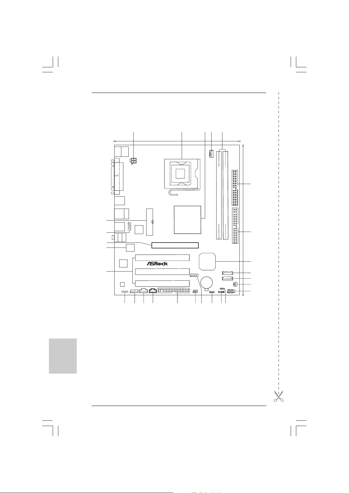
ASRock 775i65G Motherboard
11
1
11
EnglishEnglish
EnglishEnglish
English
Motherboard LMotherboard L
Motherboard L
Motherboard LMotherboard L
ayoutayout
ayout
ayoutayout
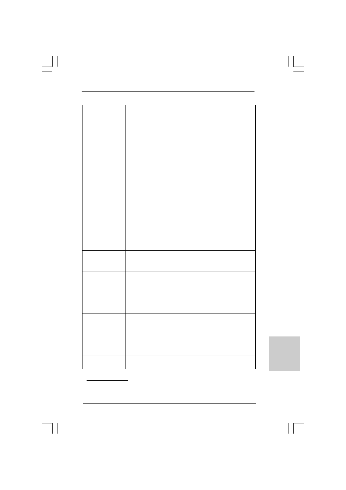
1
2
3
5
4
20.3cm (8.0in)
Keyboard
Mouse
PS2
PS2
CPU_FAN1
COM1
ATX12V 2
PARALLEL PORT
VGA1
USB2.0
T: US B2
B:USB3
USB2.0
Top:
T: US B0
RJ-45
B:USB1
27
26
25
24
23
USB2.0
T: US B4
B:USB5
Bottom:
MicIn
1
USB4_5
Center:
LineOut
Top:
LineIn
4Mb
BIOS
LAN
PHY
Audio
CODEC
JR1
JL1
1
ATXPWR1
Super
I/O
PCI1
PCI2
RoHS
PCI3
AUX1
AUDIO1
CD1
FLOPPY1
Intel
865G
Chipset
1.5V_AGP1
1
FSB1066
775i65G
Intel
ICH5
USB67
CMOS
Battery
IR1
CLRCMOS0
1
1
FSB800
DDR1 (64/72bit, 184-pin module)
DDR2 (64/72bit, 184-pin module)
SATA2
SATA1
PLED1
1
SPEAKER1
1
1
PANEL1
PLEDPWRBTN
HDLED RESET
IDE2
IDE1
ErP/EuP Ready
CHA_FAN1
6
24.4cm (9.6in)
7
8
9
10
11
12
English
EnglishEnglish
EnglishEnglish
22
2
22
17
22
20
21
19
18
15
13
16
14
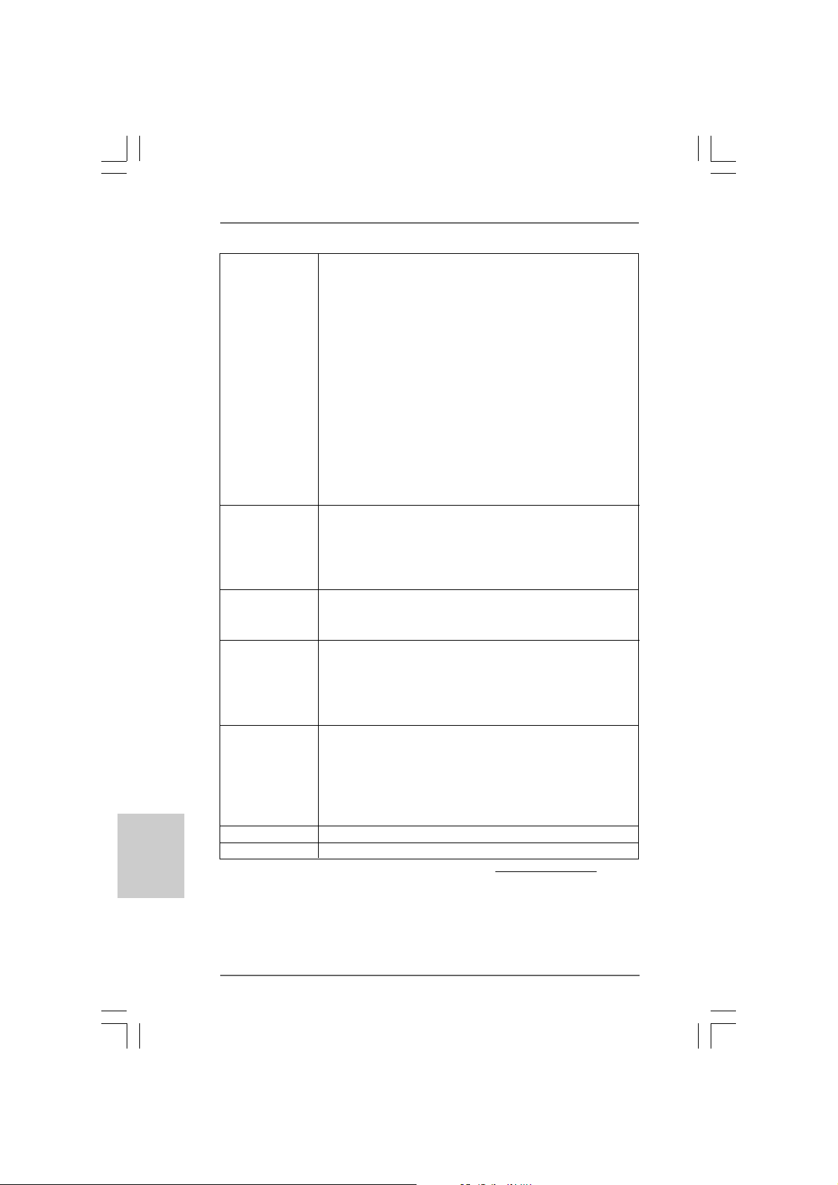
1 ATX 12V Connector (ATX12V2) 15 Clear CMOS Jumper (CLRCMOS0)
2 775-Pin CPU Socket 16 USB 2.0 Header (USB67)
3 North Bridge Controller 17 Infrared Module Header (IR1)
4 CPU Fan Connector (CPU_FAN1) 18 Floppy Connector (FLOPPY1)
5 184-pin DDR DIMM Slots (DDR1- 2) 19 Internal Audio Connector: CD1 (Black)
6 Secondary IDE Connector (IDE2, Black) 20 Internal Audio Connector: AUX1 (White)
7 Primary IDE Connector (IDE1, Blue) 21 Front Panel Audio Header (AUDIO1)
8 South Bridge Controller 22 JR1 / JL1 Jumpers
9 Secondary Serial ATA Connector (SATA2) 23 PCI Slots (PCI1- 3)
10 Primary Serial ATA Connector (SATA1) 24 BIOS FWH Chip
11 Chassis Fan Connector (CHA_FAN1) 25 AGP Slot (1.5V_AGP1)
12 System Panel Header (PANEL1) 26 Shared USB 2.0 Header (USB4_5)
13 Power LED Header (PLED1) 27 ATX Power Connector (ATXPWR1)
14 Chassis Speaker Header (SPEAKER1)
ASRock 775i65G Motherboard
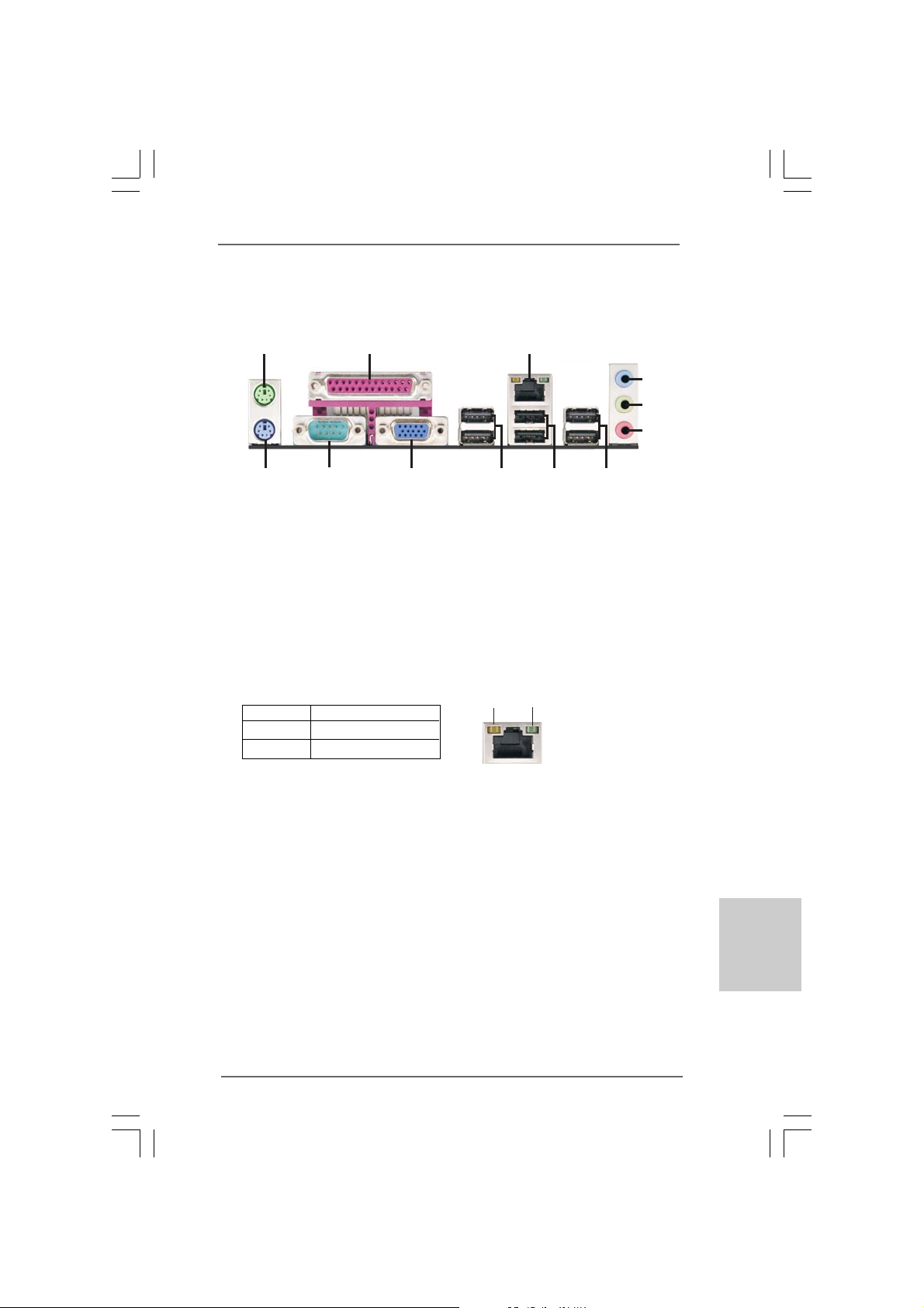
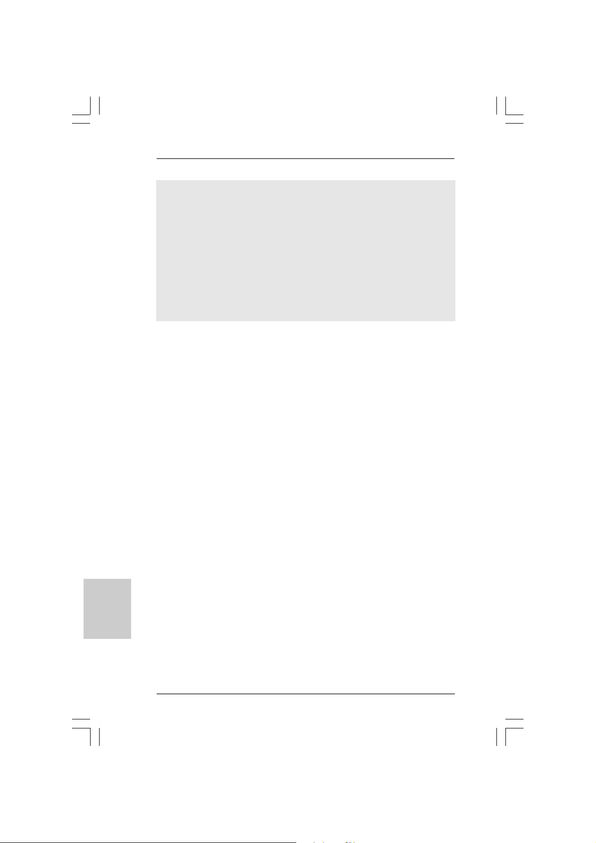
I/O PI/O P
I/O P
I/O PI/O P
anelanel
anel
anelanel
9
LAN Port
3
4
5
6
8
7
1
12
1 PS/2 Mouse Port (Green) 7 Shared USB 2.0 Ports (USB45)
2 Parallel Port 8 USB 2.0 Ports (USB01)
* 3 RJ-45 Port 9 USB 2.0 Ports (USB23)
4 Line In (Light Blue) 10 VGA Port
5 Line Out (Lime) 11 Serial Port: COM1
6 Microphone (Pink) 12 PS/2 Keyboard Port (Purple)
* There are two LED next to the LAN port. Please refer to the table below for the LAN port LED
indications.
SPEED LED
Status Description
Yellow 10Mbps connection
Green 100Mbps connection
LAN Port LED Indications
11
2
10
10Mbps 100Mbps
ASRock 775i65G Motherboard
33
3
33
EnglishEnglish
EnglishEnglish
English

1. Introduction1. Introduction
1. Introduction
1. Introduction1. Introduction
Thank you for purchasing ASRock 775i65G motherboard, a reliable motherboard
produced under ASRock’s consistently stringent quality control. It delivers excellent
performance with robust design conforming to ASRock’s commitment to quality and
endurance.
This Quick Installation Guide contains introduction of the motherboard and step-bystep installation guide. More detailed information of the motherboard can be found in
the user manual presented in the Support CD.
Because the motherboard specifications and the BIOS software might
be updated, the content of this manual will be subject to change without
notice. In case any modifications of this manual occur, the updated
version will be available on ASRock website without further notice. You
may find the latest VGA cards and CPU support lists on ASRock website
as well. ASRock website http://www.asrock.com
If you require technical support related to this motherboard, please visit
our website for specific information about the model you are using.
www.asrock.com/support/index.asp
1.1 P1.1 P
ackack
1.1 P
1.1 P1.1 P
ASRock 7775i65G Motherboard
(Micro ATX Form Fa ctor: 9.6-in x 8.0-in, 24.4 cm x 20.3 cm)
ASRock 775i65G Quick Installation Guide
ASRock 775i65G Support CD
One 80-conductor Ultra AT A 66/100 IDE Ribbon Ca ble
One Serial AT A (SA TA) Data Cable (Optional)
One I/O Panel Shield
age Contentsage Contents
ack
age Contents
ackack
age Contentsage Contents
English
EnglishEnglish
EnglishEnglish
44
4
44
ASRock 775i65G Motherboard
1.21.2
SpecificationsSpecifications
1.2
Specifications
1.21.2
SpecificationsSpecifications
Platform - Micro ATX Form Factor: 9.6-in x 8.0-in, 24.4 cm x 20.3 cm
CPU - LGA 775 for Intel® Dual-Core CoreTM 2 Extreme / CoreTM 2 Duo
/ Pentium® D / Pentium® 4 / Celeron® D
- FSB 1066 MHz for external gra phics (see CAUTION 1)
- FSB 800/533 MHz for internal gra phics
- Supports Hyper-Threading Technology (see CAUTION 2)
- Supports Untied Overclocking Te chnology (see CAUTION 3)
- Supports EM64T CPU
Chipset - Northbridge: Intel® 865G
- Southbridge: Intel® ICH5
Memory - Dual Channel DDR Memory Technology (see CAUTION 4)
- 2 x DDR DIMM slots
- Support DDR400/333/266 (see CAUTION 5)
- Max. capacity: 2GB
Expansion Slot - 3 x PCI slots
- 1 x AGP slot f or 1.5V 8X/4X AGP card (see CAUTION 6)
Graphics - Integrated Intel® Extreme Graphics 2
- DirectX 8.0
- Max. shared memory 96MB
- Supports D-Sub with max. resolution up to 2048x1536 @ 75Hz
Audio - 5.1 CH Audio (C-Media 9761A Audio Codec)
LAN - Realtek PCI LAN 8101L
- Speed: 10/100 Ethernet
- Supports Wa ke-On-LAN
- Supports PXE
Rear Panel I/O I/O Panel
- 1 x PS/2 Mouse Port
- 1 x PS/2 Keyboard Port
- 1 x Serial Port: COM1
- 1 x VGA Port
- 1 x Parallel Port (ECP/EPP Support)
- 6 x Ready-to-Use USB 2.0 Ports
- 1 x RJ-45 LAN Port with LED (SPEED LED)
- Audio Ja ck: Line In / Line Out / M icrophone
EnglishEnglish
EnglishEnglish
English
ASRock 775i65G Motherboard
55
5
55
English
EnglishEnglish
EnglishEnglish
Connector - 2 x SATA 1.5Gb/s connectors
(No Support for “RAID” and “Hot Plug” functions)
- 2 x AT A100 IDE connectors (support 4 x IDE devices )
- 1 x Floppy connector
- 1 x IR header
- 1 x Power LED header
- 1 x CPU Fan connector (4-pin)
- 1 x Chassis Fan connector (3-pin)
- 20 pin A TX power connector
- 4 pin 12V power connector
- CD in header
- AUX in header
- Front panel audio connector
- 2 x USB 2.0 headers (support 4 USB 2.0 ports; 2 of them are
shared with USB45) (see CAUTION 7)
BIOS Feature - 4Mb AMI Legal BIOS
- Supports “Plug and Play”
- ACPI 1.1 Compliance Wake Up Events
- Supports jumperfree
- SMBIOS 2.3.1 Support
Support CD - Drivers, Utilities, AntiV irus Software (T ri al Version), CyberLink
MediaEspresso 6.5 Tri al, ASRock MAGIX Multimedia Suite OEM
Unique Feature - ASRock APP Charger (see CAUTION 8)
- Hybrid Booster:
- CPU Frequency Stepless Control (see CAUTION 9)
- ASRock U-COP (see CAUTION 10)
- Boot Failure Guard (B.F.G.)
Hardware - CPU T e mperature Sensing
Monitor - Chassis Temperature Sensing
- CPU Fan Ta chometer
- Chassis Fa n Tachometer
- CPU Quiet Fan
- Voltage Monitoring: +12V, +5V, +3.3V, Vcore
OS - Microsoft® Windows® 98SE/ME/2000/XP compliant
Certifications - FCC, CE, WHQL
* For detailed product information, please visit our website: http://www.asrock.com
66
6
66
ASRock 775i65G Motherboard

WAR NING
Please realize that there is a certain risk involved with overclocking, including
adjusting the setting in the BIOS, applying Untied Overclocking Technology, or using
the third-party overclocking tools. Overclocking may affect your system stability, or
even cause damage to the components and devices of your system. It should be
done at your own risk and expense. We are not responsible for possible damage
caused by overclocking.
CAUTION!
1. FSB1066-CPU is supported only when you install AGP VGA card into
AGP slot. Besides, if you use a FSB1066-CPU on this motherboard,
please adopt a DDR400 CL2.5 memory module.
2. About the setting of “Hyper Threading Technology”, please check page
29 of “User Manual” in the support CD.
3. This motherboard supports Untied Overclocking Technology. Please read
“Untied Overclocking Technology” on page 19 for details.
4. This motherboard supports Dual Channel Memory Technology. Before
you implement Dual Channel Memory Technology, make sure to read
the installation guide of memory modules on page 13 for proper
installation.
5. Please check the table below for the memory support frequency and its
corresponding CPU FSB frequency.
CPU FSB Frequency Memory Support Frequency
800 DDR266, DDR320
533 DDR266, DDR333
* When you use an FSB800-CPU on this motherboard, it will run at
DDR320 if you adopt a DDR333 memory module.
6. Do NOT use a 3.3V AGP card on the AGP slot of this motherboard!
It may cause permanent damage!
7. Power Management for USB 2.0 works fine under Microsoft
XP SP1 or SP2 / 2000 SP4. It may not work properly under Microsoft
Windows® 98/ ME.
8. If you desire a faster, less restricted way of charging your Apple devices,
such as iPhone/iPod/iPad Touch, ASRock has prepared a wonderful
solution for you - ASRock APP Charger. Simply installing the APP Charger
driver, it makes your iPhone charged much quickly from your computer
and up to 40% faster than before. ASRock APP Charger allows you to
quickly charge many Apple devices simultaneously and even supports
continuous charging when your PC enters into Standby mode (S1),
hibernation mode (S4) or power off (S5). With APP Charger driver
installed, you can easily enjoy the marvelous charging experience than
ever.
ASRock website: http://www.asrock.com/Feature/AppCharger/index.asp
*, DDR400
®
Windows
®
®
EnglishEnglish
EnglishEnglish
English
ASRock 775i65G Motherboard
77
7
77
9. Although this motherboard offers stepless control, it is not recom-
mended to perform over-clocking. Frequencies other than the recommended CPU bus frequencies may cause the instability of the system
or damage the CPU.
10. While CPU overheat is detected, the system will automatically shutdown.
Before you resume the system, please check if the CPU fan on the
motherboard functions properly and unplug the power cord, then plug it
back again. To improve heat dissipation, remember to spray thermal
grease between the CPU and the heatsink when you install the PC
system.
English
EnglishEnglish
EnglishEnglish
88
8
88
ASRock 775i65G Motherboard
2. Installation2. Installation
2. Installation
2. Installation2. Installation
775i65G is a Micro A TX f orm fa ctor (9.6" x 8.0", 24.4 x 20.3 cm) motherboard. Before you
install the motherboard, study the configuration of your chassis to
ensure that the motherboard fits into it.
Make sure to unplug the power cord before installing or removing the
motherboard. Failure to do so may cause physical injuries to you and
damages to motherboard components.
2.1 Screw Holes2.1 Screw Holes
2.1 Screw Holes
2.1 Screw Holes2.1 Screw Holes
Place screws into the holes indicated by circles to secure the motherboard to the cha ssis.
Do not over-tighten the screws! Doing so may damage the motherboard.
2.2 Pre-installation Precautions2.2 Pre-installation Precautions
2.2 Pre-installation Precautions
2.2 Pre-installation Precautions2.2 Pre-installation Precautions
Take note of the following precautions before you install motherboard components or
change any motherboard settings.
1. Unplug the power cord from the wall socket bef ore touching any component.
2. To avoid damaging the motherboard components due to static electricity, NEVER
place your motherboard directly on the carpet or the like. Also remember to use
a grounded wrist strap or touch a safety grounded object bef ore you ha ndle
components.
3. Hold components by the edges and do not touch the ICs.
4. Whenever you uninstall any component, pla ce it on a grounded a ntistatic pa d or
in the bag that comes with the component.
Before you install or remove any component, ensure that the power is
switched off or the power cord is detached from the power supply. Failure to
do so may cause severe damage to the motherboard, peripherals, and/or
components.
ASRock 775i65G Motherboard
99
9
99
EnglishEnglish
EnglishEnglish
English
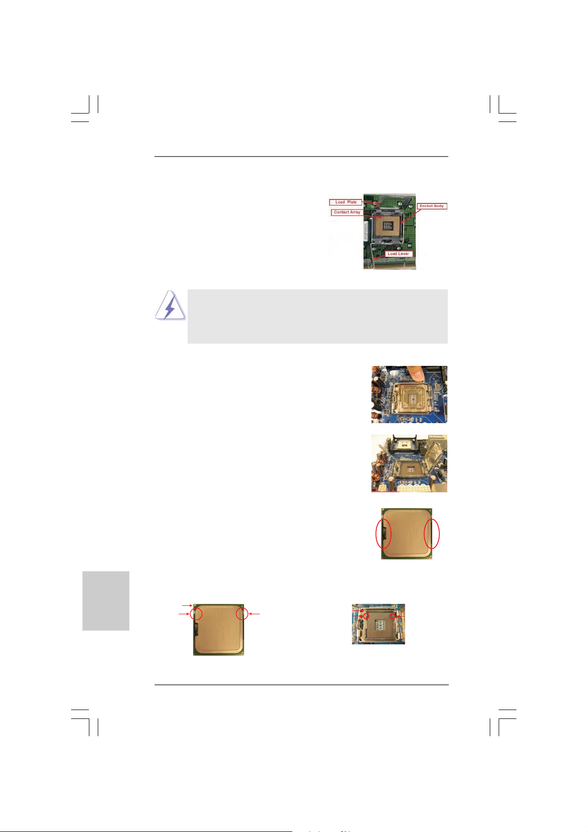
2.3 CPU Installation2.3 CPU Installation
2.3 CPU Installation
2.3 CPU Installation2.3 CPU Installation
For the installation of Intel 775-LAND CPU,
please follow the steps below.
Before you insert the 775-LAND CPU into the socket, please check if
the CPU surface is unclean or if there is any bent pin on the socket.
Do not force to insert the CPU into the socket if above situation is
found. Otherwise, the CPU will be seriously damaged.
775-Pin Socket Overview
English
EnglishEnglish
EnglishEnglish
Step 1. Open the socket:
Step 1-1. Disengaging the lever by depressing
Lift Lever Up to 90°
down and out on the hook to clear retention tab.
Step 1-2. Rotate the load lever to fully open posi-
tion at approximately 135 degree s.
Step 1-3. Rotate the load plate to fully open posi-
tion at approximately 100 degree s.
Step 2. Insert the 775-LAND CPU:
Step 2-1. Hold the CPU by the edges where are
marked with black lines.
Step 2-2. Orient the CPU with IHS (Integrated Heat
Sink) up. Locate Pin1 and the two orientation key notches.
Pin1
orientation
key notch
orientation
key notch
CPU Marked Corner
Socket Marked Corner
alignment key
Pin1
black line
black line
alignment key
1010
10
1010
775-Pin Socket
775-LAND CPU
ASRock 775i65G Motherboard
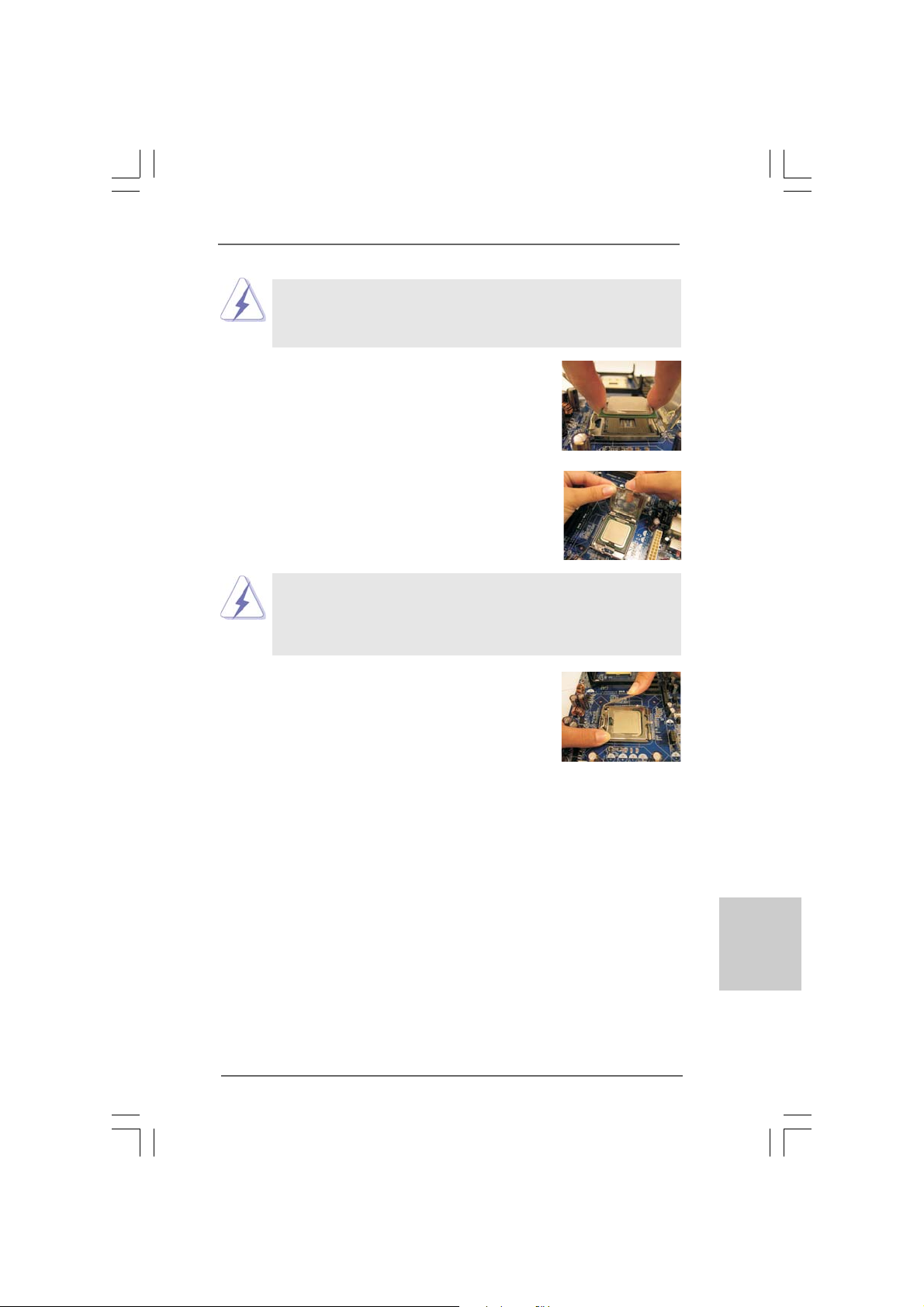
For proper inserting, please ensure to match the two orientation
key notches of the CPU with the two alignment keys of the
socket.
Step 2-3. Carefully place the CPU into the socket
by using a purely vertical motion.
Step 2-4. Verify that the CPU is within the socket
and properly mated to the orient keys.
Step 3. Remove PnP Ca p (Pick a nd Place Cap):
Use your left hand index finger a nd thumb to support the load plate edge, engage PnP ca p with right
hand thumb a nd peel the ca p from the socket while
pressing on center of PnP ca p to a ssist in removal.
1. It is recommended to use the cap tab to handle and avoid kicking
off the PnP cap.
2. This cap must be placed if returning the motherboard for after
service.
Step 4. Close the socket:
Step 4-1. Rotate the load plate onto the IHS.
Step 4-2. While pressing down lightly on load
plate, engage the load lever.
Step 4-3. Secure load lever with load plate tab
under retention tab of load lever.
ASRock 775i65G Motherboard
1111
11
1111
EnglishEnglish
EnglishEnglish
English
2.42.4
Installation of CPU Fan and HeatsinkInstallation of CPU Fan and Heatsink
2.4
Installation of CPU Fan and Heatsink
2.42.4
Installation of CPU Fan and HeatsinkInstallation of CPU Fan and Heatsink
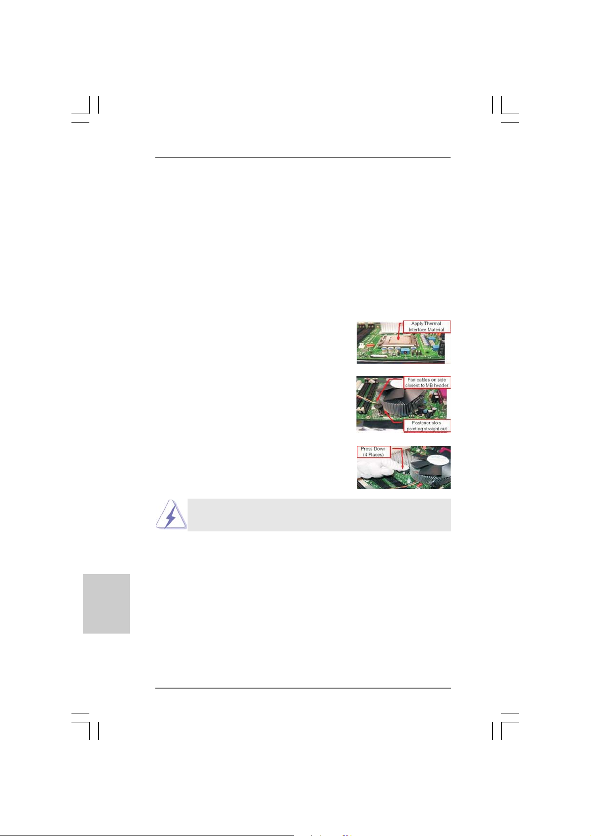
This motherboard is equipped with 775-Pin socket that supports Intel 775-LAND CPU.
Plea se adopt the type of heatsink a nd cooling fa n compli a nt with Intel 775-LAND CPU to
dissipate heat. Before you installed the heatsink, you need to spray thermal interface
material between the CPU and the heatsink to i mprove heat dissipation. Ensure that the
CPU and the heatsink are securely fastened and in good conta ct with e ach other. Then
connect the CPU fan to the CPU_F AN connector (CPU_FAN1, see page 2, No. 4).
For proper installation, please kindly refer to the instruction manuals of your
CPU fan and heatsink.
Below is an example to illustrate the installation of the heatsink for 775-LAND CPU.
Step 1. Apply thermal interface material onto center of
IHS on the socket surface.
Step 2. Place the heatsink onto the socket. Ensure fan
cables are oriented on side closest to the CPU
fan connector on the motherboard (CPU_F AN1,
see page 2, No. 4).
Step 3. Align fasteners with the motherboard
throughholes.
Step 4. Rotate the fastener clockwise, then press down
on fastener caps with thumb to install and lock.
Repeat with remaining fa steners.
English
EnglishEnglish
EnglishEnglish
1212
12
1212
If you press down the fasteners without rotating them clockwise,
the heatsink cannot be secured on the motherboard.
Step 5. Connect fan header with the CPU fan connector
on the motherboard.
Step 6. Secure excess cable with tie-wrap to ensure
cable does not interfere with fan operation or
contact other components.
ASRock 775i65G Motherboard
2.5 Installation of Memor2.5 Installation of Memor
2.5 Installation of Memor
2.5 Installation of Memor2.5 Installation of Memor
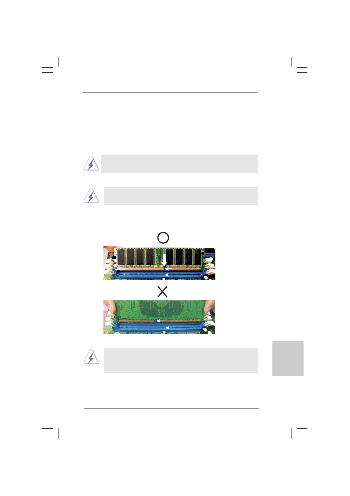
This motherboard provides two 184-pin DDR (Double Data Rate) DIMM slots, and supports
Dual Channel Memory Technology. For dual cha nnel configuration, you always need to
install two identical (the same brand, speed, size and chip-type) memory modules in
the DDR DIMM slots to activate Dual Channel Memory Technology. Otherwise, it will
operate at single channel mode.
If you install only one memory module or two non-identical memory
modules, it is unable to activate the Dual Channel Memory Technology.
Installing a DIMMInstalling a DIMM
Installing a DIMM
Installing a DIMMInstalling a DIMM
Please make sure to disconnect power supply before adding or
removing DIMMs or the system components.
Step 1. Unlock a DIMM slot by pressing the retaining clips outward.
Step 2. Align a DIMM on the slot such that the notch on the DIMM matches the break
on the slot.
y Modules (DIMM)y Modules (DIMM)
y Modules (DIMM)
y Modules (DIMM)y Modules (DIMM)
notch
break
notch
break
The DIMM only fits in one correct orientation. It will cause permanent
damage to the motherboard and the DIMM if you force the DIMM into the
slot at incorrect orientation.
Step 3. Firmly insert the DIMM into the slot until the retaining clips at both ends fully
sna p back in place a nd the DIMM is properly seated.
ASRock 775i65G Motherboard
1313
13
1313
EnglishEnglish
EnglishEnglish
English
2.6 Expansion Slots (PCI and AGPSlots)2.6 Expansion Slots (PCI and AGPSlots)
2.6 Expansion Slots (PCI and AGPSlots)
2.6 Expansion Slots (PCI and AGPSlots)2.6 Expansion Slots (PCI and AGPSlots)
There are 3 PCI slots and 1 A GP slot on this motherboard.
PCI slots: The PCI slots are used to install expansion cards that have the 32-bit
PCI interface.
AGP slot: The AGP slot is used to install a graphics card. The ASRock AGP slot has
a special design of cla sp that can securely fasten the inserted graphics
card.
Do NOT use a 3.3V AGP card on the AGP slot of this motherboard!
It may cause permanent damage!
Installing an expansion cardInstalling an expansion card
Installing an expansion card
Installing an expansion cardInstalling an expansion card
Step 1. Before installing the expansion card, plea se make sure that the power
supply is switched off or the power cord is unplugged. Plea se re a d the
documentation of the expansion card a nd ma ke nece ssary hardware
settings for the card before you start the installation.
Step 2. Remove the system unit cover (if your motherboard is already installed in a
chassis).
Step 3. Remove the bracket facing the slot that you intend to use. Keep the screws
for later use.
Step 4. Align the card connector with the slot and press firmly until the card is
completely seated on the slot.
Step 5. Fasten the card to the chassis with screws.
Step 6. Replace the system cover.
English
EnglishEnglish
EnglishEnglish
1414
14
1414
ASRock 775i65G Motherboard
2.7 Jumpers Setup2.7 Jumpers Setup
2.7 Jumpers Setup
2.7 Jumpers Setup2.7 Jumpers Setup
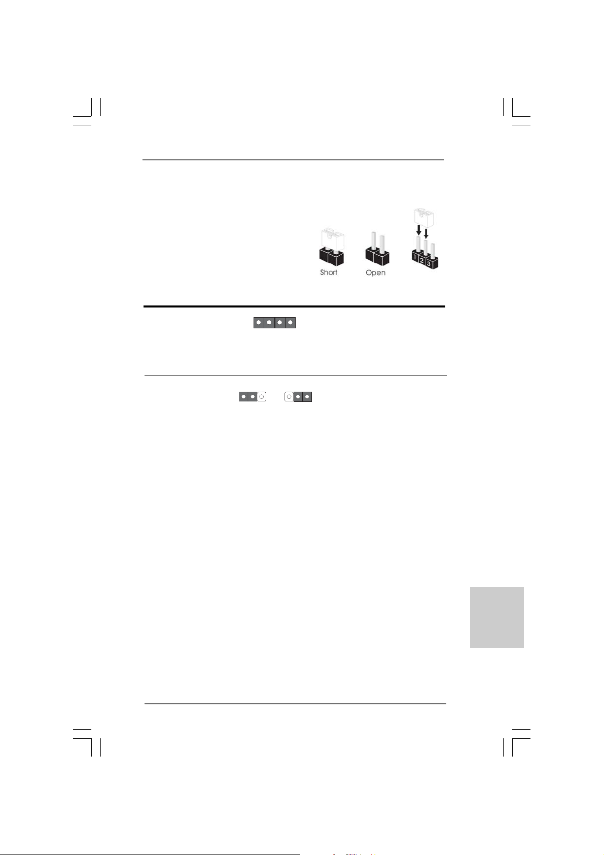
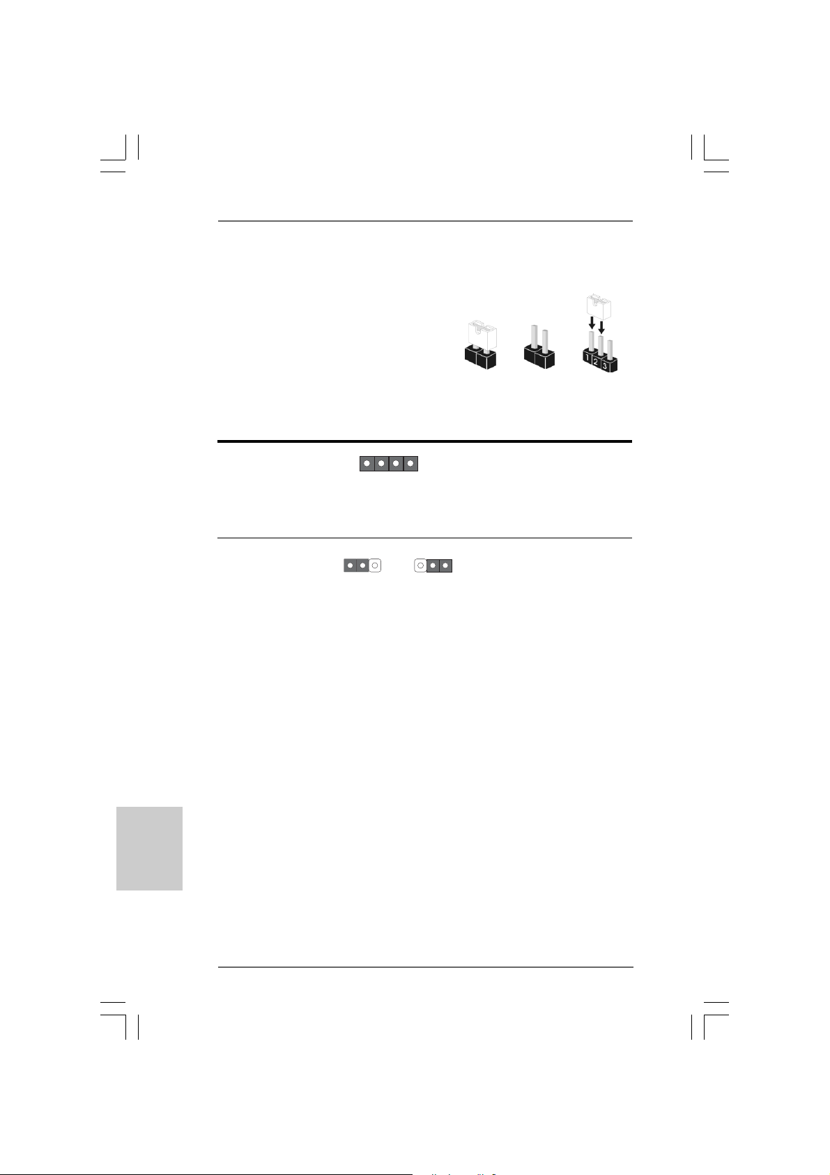
The illustration shows how jumpers are setup.
When the jumper cap is placed on
pins, the jumper is “Short”. If no jumper cap is
placed on pins, the jumper is “Open”. The illustration shows a 3-pin jumper whose pin1
an d pin2 are “Short” when jumper cap is placed
on these 2 pins.
Jumper Setting Description
JR1 (see p.2 No. 22)
JL1 (see p.2 No. 22)
Note: If the jumpers JL1 and JR1 are short, both the front panel and the rear pa nel
audio connectors can work.
JR1 JL1
Clear CMOS Jumper
(CLRCMOS0)
(see p.2 No. 15)
Note: CLRCMOS0 allows you to clear the data in CMOS. The data in CMOS includes
system setup information such as system password, date, time, and system
setup parameters. To clear and reset the system parameters to default setup,
please turn off the computer and unplug the power cord from the power supply.
After waiting for 15 seconds, use a jumper ca p to short pin2 and pin3 on CLRCMOS0
for 5 seconds. However, ple ase do not clear the CMOS right after you update the
BIOS. If you need to clear the CMOS when you just finish updating the BIOS, you
must boot up the system first, and then shut it down before you do the clearCMOS action.
1_2
Default
2_3
Clear CMOS
EnglishEnglish
EnglishEnglish
English
ASRock 775i65G Motherboard
1515
15
1515
2.8 Onboard Headers and Connectors2.8 Onboard Headers and Connectors
2.8 Onboard Headers and Connectors
2.8 Onboard Headers and Connectors2.8 Onboard Headers and Connectors
Onboard headers and connectors are NOT jumpers. Do NOT place
jumper caps over these headers and connectors. Placing jumper
caps over the headers and connectors will cause permanent damage of the motherboard!
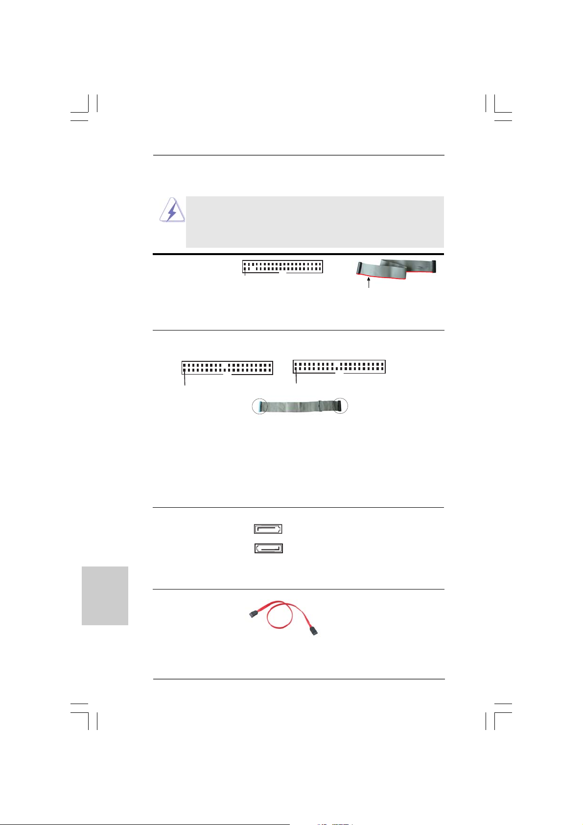
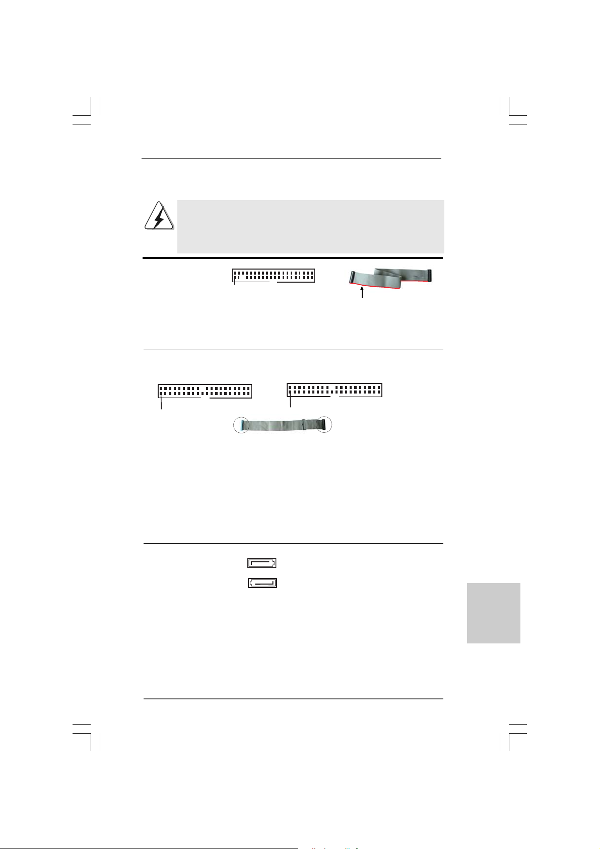
F DD connector
(33-pin FLOPPY1)
(see p.2 No. 18)
Note: Make sure the red-striped side of the cable is plugged into Pin1 side of the
Pin1
FLOPPY1
the red-striped side to
Pin1
connector.
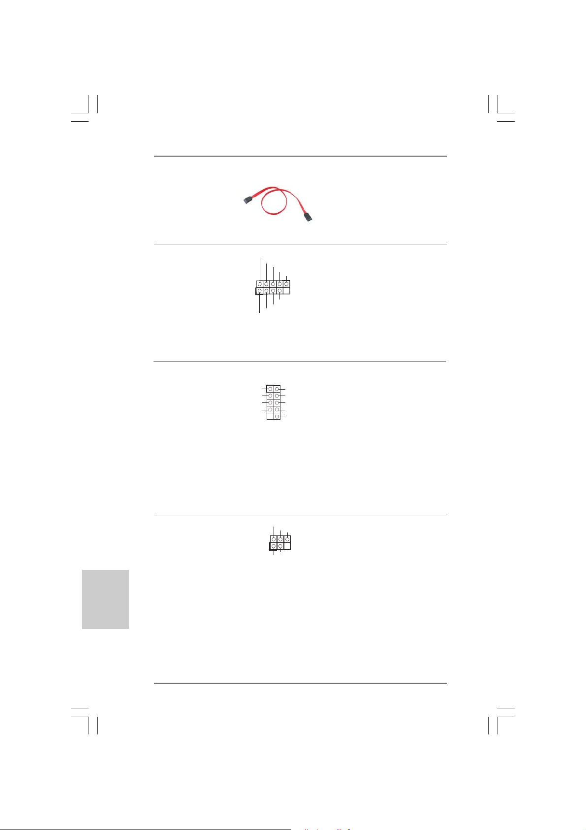
Primary IDE connector (Blue) Secondary IDE connector (Black)
(39-pin IDE1, see p.2 No. 7) (39-pin IDE2, see p.2 No. 6)
English
EnglishEnglish
EnglishEnglish
PIN1
IDE1
connect the blue end
to the motherboard
PIN1
IDE2
connect the black end
to the IDE devices
80-conductor AT A 66/100 cable
Note: If you use only one IDE device on this motherboard, please set the IDE
device as “Master”. Plea se refer to the instruction of your IDE device vendor
for the details. Besides, to optimize compatibility a nd performance, please
connect your hard disk drive to the primary IDE connector (IDE1, blue) an d
CD-ROM to the secondary IDE connector (IDE2, black).
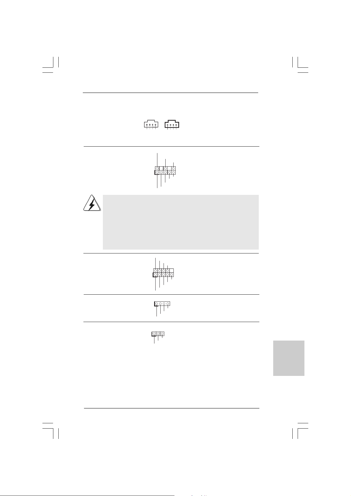
Serial AT A Connectors These two Serial AT A (SA TA)
(SATA1: see p.2 No. 10) connectors support SATA data
(SATA2: see p.2 No. 9) cables for internal storage
SAT A2
SAT A1
devices. The current SA T A
interface allows up to 1.5 Gb/s
data transfer rate.
Serial A TA (SA T A) Either end of the SATA data cable
Data Cable can be connected to the SATA
hard disk or the SATA connector
on the motherboard.
1616
16
1616
ASRock 775i65G Motherboard
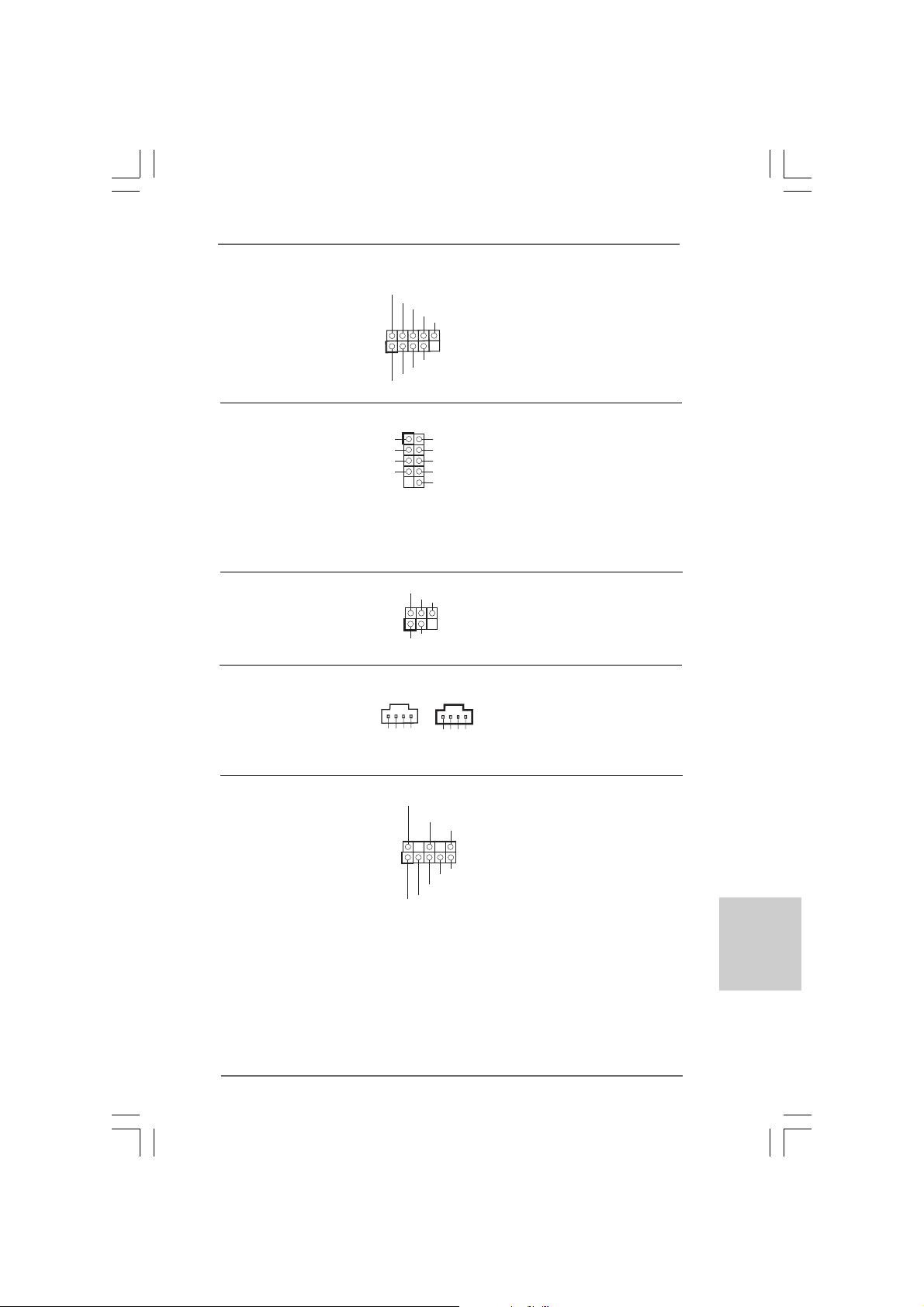
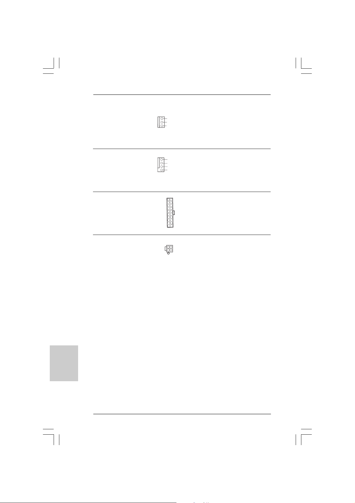
USB 2.0 Header The I/O panel accommodate s
CD-L
GND
GND
CD-R
AUX-L
GND
GND
AUX-R
(9-pin USB67) 6 default USB 2.0 ports. If those
(see p.2 No. 16) USB 2.0 ports on the I/O panel
1
USB_PWR
P-7
P-6
USB_PWR
P+7
P+6
GND
GND
DUMMY
are not sufficient, this USB 2.0
header is available to support 2
additional USB 2.0 ports.
Shared USB 2.0 Header This USB4_5 connector is shared
(9-pin USB4_5) with the USB 2.0 ports 4,5 on
(see p.2 No. 26) the I/O panel. When using the front
USB_PWR
P+5
GND
1
P-5
USB_PWR
P-4
P+4
GND
DUMMY
panel USB ports by attaching the
front panel USB cable to this
connector (USB4_5), the USB
ports 4,5 on the I/O panel will not
be able to function.
Infrared Module Header This header supports an
(5-pin IR1) optional wireless transmitting
(see p.2 No. 17) and receiving infrared module.
Internal Audio Connectors These connectors allow you
(4-pin CD1, 4-pin AUX1) to receive stereo audio input
(CD1: see p.2 No. 19) from sound sources such as
(AUX1: see p.2 No. 20) a CD-ROM, DVD-ROM, TV
1
AUX1
IRTX
IRRX
+5VSB
GND
DUMMY
CD1
tuner card, or MPEG card.
Front Panel AC’97 Audio Header This is an interface f or front
1
GND
MIC-POWER
MIC
BACKOUT-R
BACKOUT-L
AUD-OUT- L
GND
AUD-OUT- R
control of audio devices.
(8-pin AUDIO1) panel audio cable that allows
(see p.2 No. 21) convenient connection and
EnglishEnglish
EnglishEnglish
English
1717
17
ASRock 775i65G Motherboard
1717
1. +5VA is used for audio power only, please don’t connect it to any
other power, such as USB.
2. HD (Azalia) audio front panel and AC’97 audio front panel have
different pin-definition. Incorrect connection of the audio front panel
and the front panel audio header may cause permanent damage
to this motherboard.
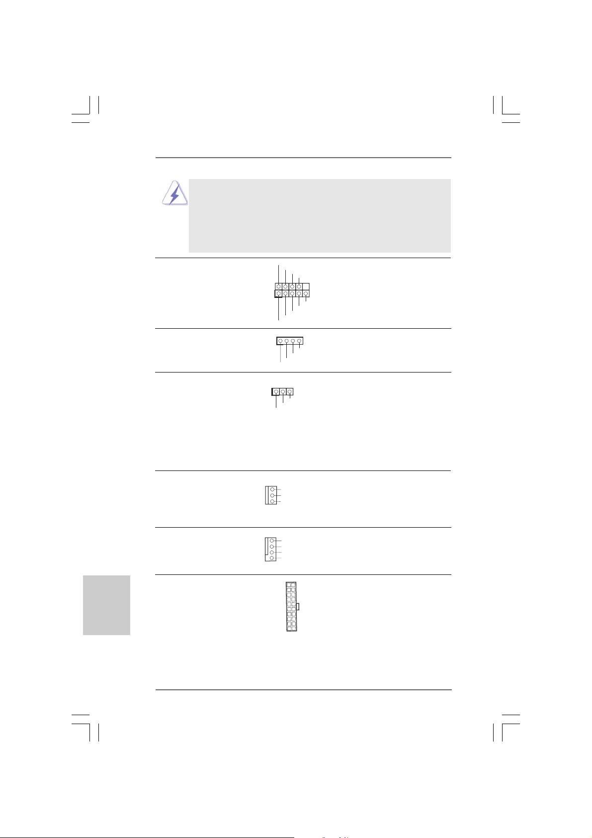
1
1
PLED+
PLED-
HDLED -
HDLED +
DUMMY
+5V
PWRBTN#
GND
DUMMY
RESET#
GND
SPEAKER
DUMMY
System Panel Header This header a ccommodates
(9-pin PANEL1) several system front pa nel
(see p.2 No. 12) functions.
Chassis Spea ker Hea der Please connect the chassis
(4-pin SPEAKER 1) speaker to this header.
(see p.2 No. 14)
Power LED Header Please connect the cha ssis power
(3-pin PLED1) LED to this header to indicate
(see p.2 No. 13) system power status. The LED is
1
PLED+
PLED+
PLED-
on when the system is operating.
The LED keeps blinking in S1
state. The LED is off in S4
state or S5 state (power off).
Cha ssis Fan Connector Please connect a chassis fan
(3-pin CHA_FAN1) cable to this connector and
(see p.2 No. 11) match the black wire to the
GND
+12V
CHA_FAN_SPEED
ground pin.
CPU Fan Connector Plea se connect a CPU fan cable
(4-pin CPU_FAN1) to this connector and match
(see p.2 No. 4) the bla ck wire to the ground pin.
GND
+12V
CPU_FAN_SPEED
FAN_SPEED _CONTROL
English
EnglishEnglish
EnglishEnglish
1818
18
1818
ATX Power Conne ctor Please connect an A TX power
(20-pin ATXPWR1) supply to this connector.
(see p.2 No. 27)
ASRock 775i65G Motherboard
ATX 12V Connector Please note that it is necessary
(4-pin ATX12V2) to connect a power supply with
(see p.2 No. 1) A TX 12V plug to this connector
so that it can provides sufficient
power. Failing to do so will cause
the failure to power up.
2.9 Driver Installation Guide2.9 Driver Installation Guide
2.9 Driver Installation Guide
2.9 Driver Installation Guide2.9 Driver Installation Guide
To install the drivers to your system, please insert the support CD to your optical drive
first. Then, the drivers compatible to your system can be auto-detected and listed on
the support CD driver page. Please follow the order from up to bottom side to install
those required drivers. Therefore, the drivers you install can work properly.
2.102.10
Untied Overclocking TUntied Overclocking T
2.10
Untied Overclocking T
2.102.10
Untied Overclocking TUntied Overclocking T
This motherboard supports Untied Overclocking Technology, which means during
overclocking, FSB enjoys better margin due to fixed AGP / PCI bus. You may set “CPU
Host Frequency” option of BIOS setup to [Auto], which will show you the actual CPU
host frequency in the following item. Therefore, CPU FSB is untied during overclocking,
but AGP / PCI bus is in the fixed mode so that FSB can operate under a more stable
overclocking environment.
echnologyechnology
echnology
echnologyechnology
Please refer to the warning on page 7 for the possible overclocking risk
before you apply Untied Overclocking Technology.
ASRock 775i65G Motherboard
1919
19
1919
EnglishEnglish
EnglishEnglish
English
3. BIOS Information3. BIOS Information
3. BIOS Information
3. BIOS Information3. BIOS Information
The Flash Memory on the motherboard stores BIOS Setup Utility. When you start up
the computer, please press <F2> during the Power-On-Self-Test (POST) to enter
BIOS Setup utility; otherwise, POST continues with its test routines. If you wish to
enter BIOS Setup after POST, please restart the system by pressing <Ctl> + <Alt> +
<Delete>, or pressing the reset button on the system chassis.
The BIOS Setup program is designed to be user-friendly. It is a menu-driven program,
which allows you to scroll through its various sub-menus and to select among the
predetermined choices. For the detailed information about BIOS Setup, please refer
to the User Manual (PDF file) contained in the Support CD.
English
EnglishEnglish
EnglishEnglish
4. Sof4. Sof
4. Sof
4. Sof4. Sof
This motherboard supports various Microsoft® Windows® operating systems: 98SE / ME
/ 2000 / XP . The Support CD that ca me with the motherboard contains nece ssary drivers
and useful utilities that will enha nce motherboard features.
To begin using the Support CD, insert the CD into your CD-ROM drive. It will display
the Main Menu automatically if “AUTORUN” is enabled in your computer. If the Main
Menu does not appear automatically, locate and double-click on the file
“ASSETUP.EXE” from the BIN folder in the Support CD to display the menus.
tware Supportware Suppor
tware Suppor
tware Supportware Suppor
t CD informationt CD information
t CD information
t CD informationt CD information
2020
20
2020
ASRock 775i65G Motherboard
1. Einführung1. Einführung
1. Einführung
1. Einführung1. Einführung
Wir danken Ihnen für den Kauf des ASRock 775i65G Motherboard, ein zuverlässiges
Produkt, welches unter den ständigen, strengen Qualitätskontrollen von ASRock
gefertigt wurde. Es bietet Ihnen exzellente Leistung und robustes Design, gemäß der
Verpflichtung von ASRock zu Qualität und Halbarkeit.
Diese Schnellinstallationsanleitung führt in das Motherboard und die schrittweise
Installation ein. Details über das Motherboard finden Sie in der Bedienungsanleitung
auf der Support-CD.
Da sich Motherboard-Spezifikationen und BIOS-Software verändern
können, kann der Inhalt dieses Handbuches ebenfalls jederzeit geändert
werden. Für den Fall, dass sich Änderungen an diesem Handbuch
ergeben, wird eine neue Version auf der ASRock-Website, ohne weitere
Ankündigung, verfügbar sein. Die neuesten Grafikkarten und unterstützten
CPUs sind auch auf der ASRock-Website aufgelistet.
ASRock-Website: http://www.asrock.com
Wenn Sie technische Unterstützung zu Ihrem Motherboard oder spezifische
Informationen zu Ihrem Modell benötigen, besuchen Sie bitte unsere
Webseite:
www.asrock.com/support/index.asp
1.1 Kartoninhalt
ASRock 775i65G Motherboard
(Micro ATX-Formfaktor: 24.4 cm x 20.3 cm; 9.6 Zoll x 8.0 Zoll)
ASRock 775i65G Schnellinstallationsanleitung
ASRock 775i65G Support-CD
Ein 80-adriges Ultra-ATA 66/100 IDE-Flachbandkabel
Ein Seriell-ATA- (SATA) Datenkabel (Option)
Ein Seriell-ATA (SATA) Festplattennetzkabel (Option)
Ein I/O Shield
ASRock 775i65G Motherboard
2121
21
2121
DeutschDeutsch
DeutschDeutsch
Deutsch
Deutsch
DeutschDeutsch
DeutschDeutsch
1.21.2
SpezifikationenSpezifikationen
1.2
Spezifikationen
1.21.2
SpezifikationenSpezifikationen
Plattform - Micro ATX-Formfaktor: 24.4 cm x 20.3 cm; 9.6 Zoll x 8.0 Zoll
CPU - LGA 775 für Intel® Dual-Core CoreTM 2 Extreme / CoreTM 2 Duo
/ Pentium® D / Pentium® 4 / Celeron® D
- FSB 1066 MHz für externe Grafik (siehe VORSICHT 1)
- FSB 800/533 MHz für interne Grafik
- Unterstützt Hyper-Threading-Technologie
(siehe VORSICHT 2)
- Unterstützt Untied-Übertaktungstechnologie
(siehe VORSICHT 3)
- Unterstützt EM64T -CPU
Chipsatz - Northbridge: Intel® 865G
- Southbridge: Intel® ICH5
Speicher - Unterstützung von Dual-Kanal-DDR-Speichertechnologie
(siehe VORSICHT 4)
- 2 x Steckplätze für DDR
- Unterstützt DDR400/333/266 (siehe VORSICHT 5)
- Max. 2GB
Erweiterungs- - 3 x PCI -Steckplätze
steckplätze - 1x AGP -Steckplätze, unterstützt 1.5V, 8X/4X AGP-Karten
(siehe VORSICHT 6)
Onboard-VG A - Integrated Intel® Extreme Gra phics 2
- DirectX 8.0 VGA
- Maximal gemeinsam genutzter Speicher 96 MB
- Unterstützt D-Sub mit einer maximalen Auflösung von
2048 x 1536 bei 75 Hz
Audio - 5.1 CH Audio (C-Medi a 9761A Audio Codec)
LAN - Realtek PCI LAN 8101L
- Speed: 10/100 Ethernet
- Unterstützt W ake-On-LAN
- Unterstützt PXE
E/A-Anschlüsse I/O Panel
an der - 1 x PS/2 Mouse Port
Rückseite - 1 x PS/2 Keyboard Port
- 1 x Serieller port: COM 1
- 1 x VGA Port
- 1 x Parallel Port (ECP/EPP Support)
- 6 x Ready-to-Use USB 2.0 Ports
- 1 x RJ-45 LAN Port mit LED (SPEED LED)
- Audioa n schlüsse: Line In / Line Out / Mikrofon
2222
22
2222
ASRock 775i65G Motherboard
Anschlüsse - 2 x SATA-Anschlüsse, unterstützt bis 1.5 Gb/s
Datenübertragungsrate (U nterstützt keine “RAID”- und “Hot-Plug” Funktionen)
- 2 x ATA100 IDE-Anschlüsse (Unterstützt bis 4 IDE-Geräte)
- 1 x FDD-Anschlüsse
- 1 x Infrarot-Modul-Header
- 1 x Betriebs-LED-Header
- CPU-Lüfteranschluss (4-pin)
- Gehäuse-Lüfteranschluss (3-pin)
- 20-pin ATX-Netz-Header
- 4-pin anschluss für 12V-ATX-Netzteil
- Interne Audio-Anschlüsse
- Anschluss für Audio auf der Gehäusevorderseite
- 2 x USB 2.0-Anschlüsse (Unterstützt 4 USB 2.0-Ports;
2 davon werden gemeinsa m mit USB45 genutzt.)
(siehe VORSICHT 7)
BIOS - 4Mb AMI BIOS
- Unterstützung für “Plug and Play”
- ACPI 1.1-Weckfunktionen
- JumperFree-Modus
- SMBIOS 2.3.1
Support-CD - Tre iber, Dienstprogra mme, Antivirussoftware (Probeversion),
CyberLink MediaEspresso 6.5 Tri al, ASRock MAGIX Multimedia-Suite - OEM
Einzigartige - ASRock APP Charger (siehe VORSICHT 8)
Eigenschaft - Hybrid Booster:
- Schrittloser CPU-Frequenz-Kontrolle
(siehe VORSICHT 9)
- ASRock U-COP (siehe VORSICHT 10)
- Boot Failure Guard (B.F.G. – Systemstartfehlerschutz)
Hardware Monitor - Überwachung der CPU-T emperatur
- Motherboardtemperaturerkennung
- Drehza hlmessung für CPU-Lüfter
- Drehzahlmessung für Gehäuselüfter
- CPU-Lüftergeräuschdämpfung
- Spannungsüberwachung: +12V, +5V, +3.3V, Vcore
Betriebssysteme - Unterstützt Microsoft® Windows® 98SE / ME / 2000 / XP
Zertifizierungen - FCC, CE, WHQL
* Für die ausführliche Produktinformation, besuchen Sie bitte unsere Website:
http://www.asrock.com
DeutschDeutsch
DeutschDeutsch
Deutsch
ASRock 775i65G Motherboard
2323
23
2323
Deutsch
DeutschDeutsch
DeutschDeutsch
WAR NUNG
Beachten Sie bitte, dass Overclocking, einschließlich der Einstellung im BIOS, Anwenden
der Untied Overclocking-Technologie oder Verwenden von Overclocking-Werkzeugen von
Dritten, mit einem gewissen Risiko behaftet ist. Overclocking kann sich nachteilig auf die
Stabilität Ihres Systems auswirken oder sogar Komponenten und Geräte Ihres Systems
beschädigen. Es geschieht dann auf eigene Gefahr und auf Ihre Kosten. Wir übernehmen
keine Verantwortung für mögliche Schäden, die aufgrund von Overclocking verursacht
wurden.
VORSICHT!
1. Die FSB1066-CPU wird nur unterstützt, wenn Sie eine AGP-VGA-Karte
im AGP-Steckplatz installieren. Wenn Sie allerdings eine FSB1066-CPU
mit diesem Motherboard verwenden, nutzen Sie bitte ein DDR400 CL2.
5-Speichermodul.
2. Die Einstellung der “Hyper-Threading Technology”, finden Sie auf
Seite 29 des auf der Support-CD enthaltenen Benutzerhandbuches
beschrieben.
3. Dieses Motherboard unterstützt die Untied-Übertaktungstechnologie.
Unter “Entkoppelte Übertaktungstechnologie” auf Seite 19 finden Sie
detaillierte Informationen.
4. Dieses Motherboard unterstützt Dual-Kanal-Speichertechnologie. Vor
Implementierung der Dual-Kanal-Speichertechnologie müssen Sie die
Installationsanleitung für die Speichermodule auf Seite 13 zwecks
richtigerInstallation gelesen haben.
5. Die unterstützten Arbeitsspeicherfrequenzen und die entsprechende
CPU FSB-Frequenz entnehmen Sie bitte der nachstehenden Tabelle.
CPU FSB-Frequenz Unterstützte Arbeitsspeicherfrequenz
800 DDR266, DDR320
533 DDR266, DDR333
* Bei Verwendung einer FSB800-CPU auf diesem Motherboard läuft es mit
DDR320, wenn Sie ein DDR333-Speichermodul verwenden.
6. Stecken Sie KEINE 3,3V AGP-Karte in den AGP-Steckplatz dieses
Motherboards! Permanente Beschädigung könnte die Folge sein!
7. Das Power Management für USB 2.0 arbeitet unter Microsoft
Windows® XP SP1 oder SP2/2000 SP4 einwandfrei. Unter Microsoft
Windows® 98/ME könnte es dagegen zu Störungen kommen.
*, DDR400
®
®
2424
24
2424
ASRock 775i65G Motherboard
8. Wenn Sie nach einer schnelleren, weniger eingeschränkten
Möglichkeit zur Aufladung Ihrer Apple-Geräte (z. B. iPhone/iPad/iPod
touch) suchen, bietet ASRock Ihnen eine wunderbare Lösung – den
ASRock APP Charger. Installieren Sie einfach den ASRock APP
Charger-Treiber; dadurch lädt sich Ihr iPhone wesentlich schneller
über einen Computer auf – genaugenommen bis zu 40 % schneller
als zuvor. Der ASRock APP Charger ermöglicht Ihnen die schnelle
Aufladung mehrerer Apple-Geräte gleichzeitig; der Ladevorgang wird
sogar dann fortgesetzt, wenn der PC den Ruhezustand (S1) oder
Tiefschlafmodus (S4) aufruft oder ausgeschaltet wird (S5). Nach der
Installation des APP Charger-Treibers können Sie im Handumdrehen
das großartigste Ladeerlebnis überhaupt genießen.
ASRock-Webseite: http://www.asrock.com/Feature/AppCharger/index.
asp
9. Obwohl dieses Motherboard stufenlose Steuerung bietet, wird
Overclocking nicht empfohlen. Frequenzen, die von den empfohlenen
CPU-Busfrequenzen abweichen, können Instabilität des Systems
verursachen oder die CPU beschädigen.
10. Wird eine Überhitzung der CPU registriert, führt das System einen
automatischen Shutdown durch. Bevor Sie das System neu starten,
prüfen Sie bitte, ob der CPU-Lüfter am Motherboard richtig funktioniert,
und stecken Sie bitte den Stromkabelstecker aus und dann wieder ein.
Um die Wärmeableitung zu verbessern, bitte nicht vergessen, etwas
Wärmeleitpaste zwischen CPU und Kühlkörper zu sprühen.
ASRock 775i65G Motherboard
2525
25
2525
DeutschDeutsch
DeutschDeutsch
Deutsch
1.3 Einstellung der Jumper1.3 Einstellung der Jumper
1.3 Einstellung der Jumper
1.3 Einstellung der Jumper1.3 Einstellung der Jumper
Die Abbildung verdeutlicht, wie Jumper gesetzt
werden. Werden Pins durch Jumperkappen
verdeckt, ist der Jumper “Gebrückt”. Werden
keine Pins durch Jumperkappen verdeckt, ist
der Jumper “Offen”. Die Abbildung ze igt einen
3-Pin Jumper dessen Pin1 und Pin2 “Gebrückt”
sind, bzw. es befindet sich eine Jumper-Ka ppe
auf diesen beiden Pins.
Jumper Einstellun Beschreibung
JR1(siehe S.2 - Nr. 22)
JL1 (siehe S.2 - Nr. 22)
Hinweis: Sind die Jumper JL1 und JR1 gesetzt funktionieren beide
Audioanschlüsse, Front- und Rückseite.
JR1 JL1
Gebrückt Offen
Deutsch
DeutschDeutsch
DeutschDeutsch
CMOS löschen
(CLRCMOS0, 3-Pin jumper)
(siehe S.2 - Nr. 15)
Hinweis: CLRCMOS0 erlaubt Ihnen das Löschen der CMOS-Daten. Diese be inhalten
das System-Passwort, Datum, Ze it und die verschiedenen BIOS-Parameter.
Um die Systemparameter zu löschen und auf die Werksei nstellung
zurückzusetzen, schalten Sie bitte den Computer ab und entfernen das
Stromkabel. Benutzen Sie eine Jumperkappe, um die Pin 2 und Pin 3 an
CLRCMOS0 für 5 Sekunden kurzzuschließen. Bitte vergessen Sie nicht,
den Jumper wieder zu entfernen, nachdem das CMOS gelöscht wurde. Bitte
vergessen Sie nicht, den Jumper wieder zu entfernen, nachdem das CMOS
gelöscht wurde. W enn Sie den CMOS-Inhalt gleich nach dem Aktualisieren
des BIOS löschen müssen, müssen Sie zuerst das System starten und
dann wieder ausschalten, bevor Sie den CMOS-Inhalt löschen.
1_2
DefaultEinstellung
2_3
CMOS
löschen
2626
26
2626
ASRock 775i65G Motherboard
1.4 Integrierte Header und Anschlüsse1.4 Integrierte Header und Anschlüsse
1.4 Integrierte Header und Anschlüsse
1.4 Integrierte Header und Anschlüsse1.4 Integrierte Header und Anschlüsse
Integrierte Header und Anschlüsse sind KEINE Jumper. Setzen Sie KEINE
Jumperkappen auf diese Header und Anschlüsse. W enn Sie Jumperkappen
auf Header und Anschlüsse setzen, wird das Motherboard unreparierbar
beschädigt!
Anschluss für das
Floppy-Laufwerk
(33-Pin FLOPPY1)
(siehe S.2 - Nr. 18)
Pin1
FLOPPY1
die rotgestreifte Seite auf Stift 1
Hinweis: Achten Sie darauf, dass die rotgestreifte Seite des Kabel mit der Stift 1-
Seite des Anschlusses verbunden wird.
Primärer IDE-Anschluss (blau) Sekundärer IDE-Anschluss (schwarz)
(39-pin IDE1, siehe S.2 - Nr. 7) (39-pin IDE2, siehe S.2 - Nr. 6)
PIN1
IDE1
PIN1
IDE2
Blauer Anschluss Schwarzer Anschluss
zum Motherboard zur Festplatte
80-adriges A TA 66/100-Kabel
Hinweis: Wenn Sie auf diese m Motherboard nur ein IDE-Gerät einsetzen, richten Sie
das IDE-Gerät als “Master” ein. Details entnehmen Sie bitte den
Anweisungen Ihres IDE-Gerätehändlers. Zur Optimierung der Kompatibilität
und Leistung verbinden Sie die Festplatte mit dem primären IDE-Anschluss
(IDE1, blau) und das CD-ROM mit dem sekundären IDE-Anschluss (IDE2,
schwarz).
Seriell-ATA-Anschlüsse Diese beiden Serial ATA-
(SATA1: siehe S.2 - No. 10) (SAT A-)V erbínder
(SATA2: siehe S.2 - No. 9) unterstützten SATA-Datenkabel
SAT A2
SAT A1
für interne
Massen spe ichergeräte. Die
aktuelle SATA-Schnittstelle
ermöglicht eine
Datenübertragungsrate bis
1,5 Gb/s.
DeutschDeutsch
DeutschDeutsch
Deutsch
ASRock 775i65G Motherboard
2727
27
2727
Serial ATA- (SAT A-) Sie können beide Enden des
Datenkabel SATA-Datenkabels entweder mit
(Option) der SATA-Festplatte oder dem
SATA-Anschluss am Mainboard
verbinden.
Deutsch
DeutschDeutsch
DeutschDeutsch
USB 2.0-Header E/A-Anschlüsse an der Rückseite
(9-pin USB67) besitzt 6 Standard-USB 2.0-
(siehe S.2 - No. 16) Anschlüsse auf der Rückseite.
1
USB_PWR
P-7
P-6
USB_PWR
P+7
P+6
GND
GND
DUMMY
Wenn die hinteren USBAnschlüsse nicht ausreichen,
steht dieser USB 2.0-Header
(USB67) zur Unterstützung von 2
zusätzlichen USB 2.0Anschlüssen zur V erfügung.
Gemeinsam genutzter Dieser USB4_5-Header wird mit
USB 2.0-Header den USB 2.0-Anschlüssen 4,5
(9-pin USB4_5) auf E/A-Anschlüsse an der
(siehe S.2 - No. 26) Rückseite gemeinsam genutzt. Bei
USB_PWR
GND
P+5
1
P-5
USB_PWR
P-4
P+4
GND
DUMMY
Verwendung der vorderseitigen
USB-Anschlüsse durch
Verbinden des vorseitigen USBKabels mit diesem Header
(USB4_5) werden die USBAnschlüsse 4,5 auf E/AAnschlüsse an der Rückseite nicht
funktionieren.
Anschluss für Dieser Anschluss unterstützt
Infrarot-Modul einen optionalen Infrarot-
(5-Pin IR1) Sender/Empfänger.
(siehe S.2 - No. 17)
IRTX
+5VSB
DUMMY
1
GND
IRRX
2828
28
2828
ASRock 775i65G Motherboard
CD-L
GND
GND
CD-R
AUX- L
GND
GND
AUX- R
Interne Audio-Anschlüsse Diese ermöglichen Ihnen
(4-Pin CD1, 4-Pin AUX1) Stereo-Signalquellen, wie z. B.
(CD1: siehe S.2 - No. 19) CD-ROM, DV D-ROM, TV-Tuner
(AUX1: siehe S.2 - No. 20) oder MPEG-Karten mit Ihrem
AUX1
CD1
System zu verbinden.
Anschluss für AC’97 Audio auf Dieses Interface zu einem
der Gehäusevorderseite Audio-Panel auf der Vorderseite
(8-Pin AUDIO1) Ihres Gehäuses, ermöglicht
(siehe S.2 - No. 21) Ihnen eine bequeme
1
GND
MIC-POWER
MIC
BACKOUT-R
BACKOUT-L
AUD-OUT-L
GND
AUD-OUT-R
Anschlussmöglichkeit und
Kontrolle über Audio-Geräte.
1. +5VA wird nur zur Audio-Stromversorgung verwendet. Bitte schließen
Sie diesen Anschluss nicht an andere stromführende Geräte, wie
USB-Geräte an.
2. Das HD- (Azalia) Frontaudio-Anschlussfeld und das AC’97 Frontaudio-Anschlussfeld verfügen über unterschiedliche
Pinbelegungen. Der falsche Anschluss von Frontaudio
Anschlussfeld und Frontaudio-Anschlussleiste kann dauerhafte
Schäden am Motherboard verursachen.
1
1
PLED+
PLED-
HDLED-
HDLED+
DUMMY
+5V
PWRBTN#
GND
RESET#
GND
SPEAKER
DUMMY
DUMMY
System Panel Anschluss Dieser Anschluss ist für die
(9-Pin PANEL1) verschiedenen Funktionen der
(siehe S.2 - No. 12) Gehäusefront.
Gehäuselautsprecher-Header Schließen Sie den
(4-pin SPEAKER1) Gehäuselautsprecher an diesen
(siehe S.2 - No. 14) Header an.
Betriebs-LED-Header Bitte schließen Sie die
(3-pin PLED1) Betriebs-LED des Gehäuses
(siehe S.2 - No. 13) zur Anzeige des
1
PLED-
PLED+
PLED+
Systembetriebsstatus an
diesem Header an. Die LED
leuchtet, wenn das System in
DeutschDeutsch
DeutschDeutsch
Betrieb ist. Die LED blinkt im S1-
Deutsch
Zustand. Im S4- oder S5Zustand (ausgeschaltet)
leuchtet die LED nicht.
2929
29
ASRock 775i65G Motherboard
2929
Gehäuselüfteranschluss V erbinden Sie das
(3-pin CHA_FAN1) Gehäuselüfterkabel mit diesem
(siehe S.2 - No. 11) Anschluss und passen Sie den
GND
+12V
CHA_FAN_SPEED
schwarzen Draht dem
Erdungsstift an.
CPU-Lüfteranschluss Verbinden Sie das CPU -
(4-pin CPU_FAN1) Lüfterkabel mit diesem
(siehe S.2 - No. 4) Anschluss und passen Sie den
GND
+12V
CPU_FAN_SPEED
FAN_S PEED_CONTROL
schwarzen Draht dem
Erdungsstift an.
A TX-Netz-Header Verbinden Sie die A TX-
(20-pin ATXPWR1) Stromversorgung mit diesem
(siehe S.2 - No. 27) Header.
Anschluss für Beachten Sie bitte, dass Sie eine
12V-ATX-Netzteil Stromversorgung mit ATX 12-
(4-pin ATX12V2) Volt-Stecker mit diesem
(siehe S.2 - No. 1) Anschluss verbinden müssen,
damit ausreichend Strom
geliefert werden kann.
Andernfalls reicht der Strom
nicht aus, das System zu starten.
Deutsch
DeutschDeutsch
DeutschDeutsch
3030
30
3030
ASRock 775i65G Motherboard