

Page 1
Copyright Notice:Copyright Notice:
Copyright Notice:
Copyright Notice:Copyright Notice:
No part of this installation guide may be reproduced, transcribed, transmitted, or
translated in any language, in any form or by any means, except duplication of
documentation by the purchaser for backup purpose, without written consent of
ASRock Inc.
Products and corporate names appearing in this guide may or may not be registered
trademarks or copyrights of their respective companies, and are used only for
identification or explanation and to the owners’ benefit, without intent to infringe.
Disclaimer:Disclaimer:
Disclaimer:
Disclaimer:Disclaimer:
Specifications and information contained in this guide are furnished for informational
use only and subject to change without notice, and should not be constructed as a
commitment by ASRock. ASRock assumes no responsibility for any errors or
omissions that may appear in this guide.
With respect to the contents of this guide, ASRock does not provide warranty of any
kind, either expressed or implied, including but not limited to the implied warranties or
conditions of merchantability or fitness for a particular purpose.
In no event shall ASRock, its directors, officers, employees, or agents be liable for
any indirect, special, incidental, or consequential damages (including damages for
loss of profits, loss of business, loss of data, interruption of business and the like),
even if ASRock has been advised of the possibility of such damages arising from any
defect or error in the guide or product.
This device complies with Part 15 of the FCC Rules. Operation is subject to the
following two conditions:
(1) this device may not cause harmful interference, and
(2) this device must accept any interference received, including interference that
may cause undesired operation.
ASRock Website: http://www.asrock.com
Published October 2006
Copyright©2006 ASRock INC. All rights reserved.
ASRock 775Dual-VSTA Motherboard
EnglishEnglish
EnglishEnglish
English
11
1
11
Page 2
Motherboard LMotherboard L
Motherboard L
Motherboard LMotherboard L
ayoutayout
ayout
ayoutayout
English
EnglishEnglish
EnglishEnglish
22
2
22
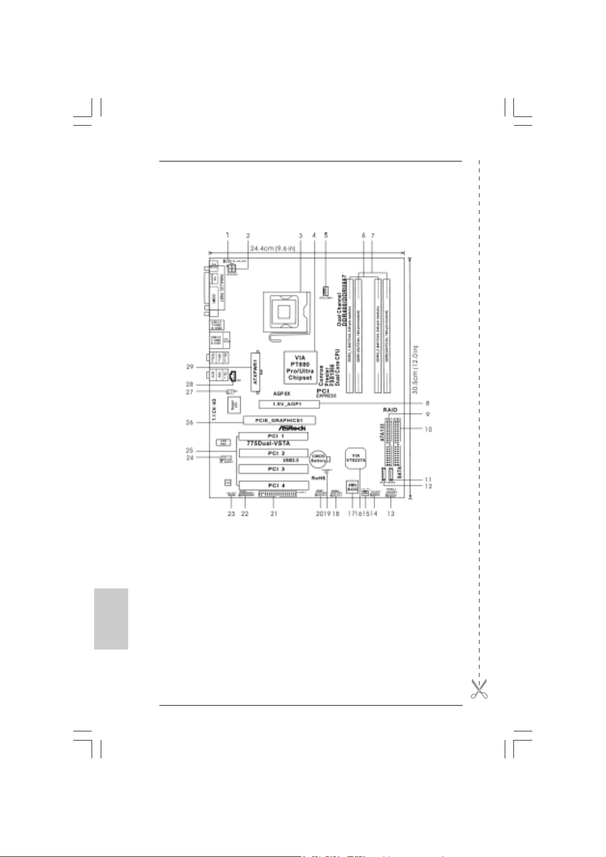
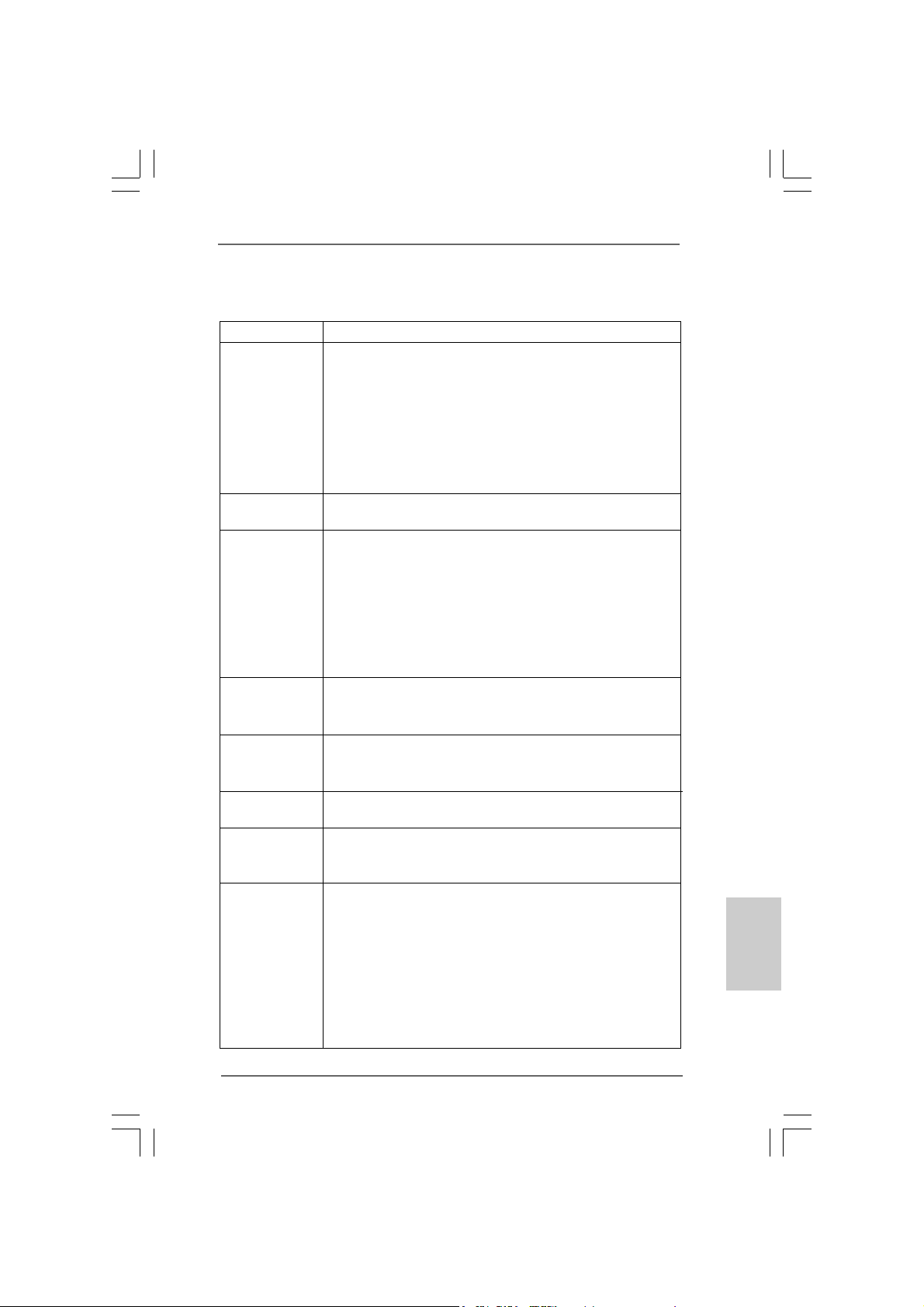
1 PS2_USB_PWR1 Jumper 15 Chassis Fan Connector (CHA_FAN1)
2 A TX 12V Connector (A TX12V1) 16 South Bridge Controller
3 775-Pin CPU Socket 17 Flash Memory
4 North Bridge Controller 18 USB 2.0 Header (USB45, Blue)
5 CPU Fan Connector (CPU_FAN1) 19 Clear CMOS Jumper (CLRCMOS1)
6 2 x 240-pin DDRII DIMM Slots 20 USB 2.0 Header (USB67, Blue)
(Dual Channel A: DDRII_1, DDRII_2; Yellow) 21 Floppy Connector (FLOPPY1)
7 2 x 184-pin DDR DIMM Slots 22 Game Connector (GAME1)
(Dual Channel B: DDR1, DDR2; Blue) 23 HDMI_SPDIF Header (HDMI_SPDIF1)
8 AGP Slot (1.5V_AGP1) 24 Front Panel Audio Header (HD_AUDIO1)
9 Primary IDE Connector (IDE1, Blue) 25 4 x PCI Slots (PCI1- 4)
10 Secondary IDE Connector (IDE2, Black) 26 PCI Express Graphics Slot
11 Secondary Serial A T A Conne ctor (SA T A2 ) 27 Infrared Module Header (IR1)
12 Primary Serial A T A Conne ctor (SA T A1) 28 Internal Audio Connector: CD1 (Black)
13 System Panel Header (P ANEL1) 29 ATX Power Connector (A TXPW R1)
14 Chassis Speaker Header (SPEAKER 1)
ASRock 775Dual-VSTA Motherboard
Page 3
HD 8CH I/OHD 8CH I/O
HD 8CH I/O
HD 8CH I/OHD 8CH I/O
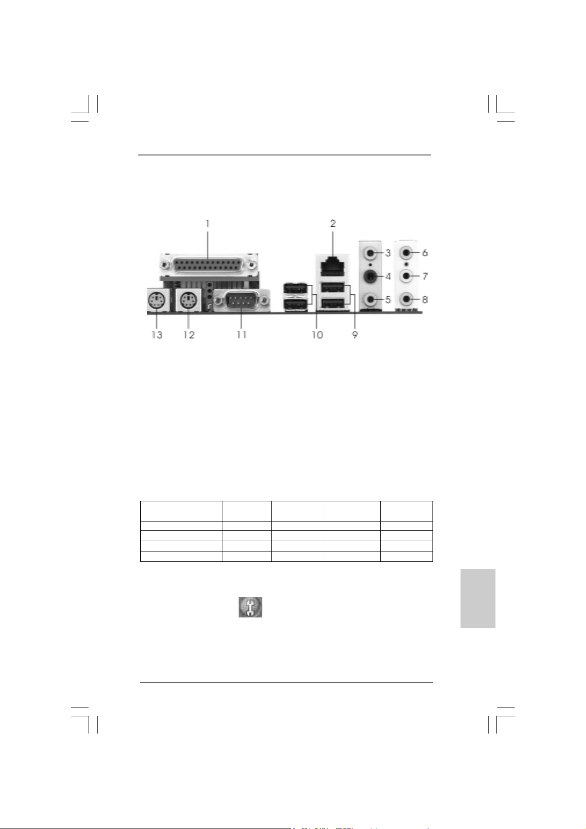
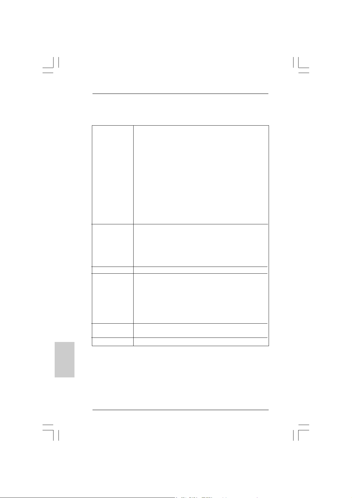
1 Parallel Port 8 Microphone (Pink)
2 RJ-45 Port 9 USB 2.0 Ports (USB01)
3 Side Speaker (Gray) 10 USB 2.0 Ports (USB23)
4 Rear Speaker (Black) 11 Serial Port: COM1
5 Central / Bass (Orange) 12 PS/2 Keyboard Port (Purple)
6 Line In (Light Blue) 13 PS/2 Mouse Port (Green)
*7 Front Speaker (Lime)
* If you use 2-channel spea ker, please connect the speaker’s plug into “Front Speaker Jack”. See
the table below for connection details in accordance with the type of speaker you use.
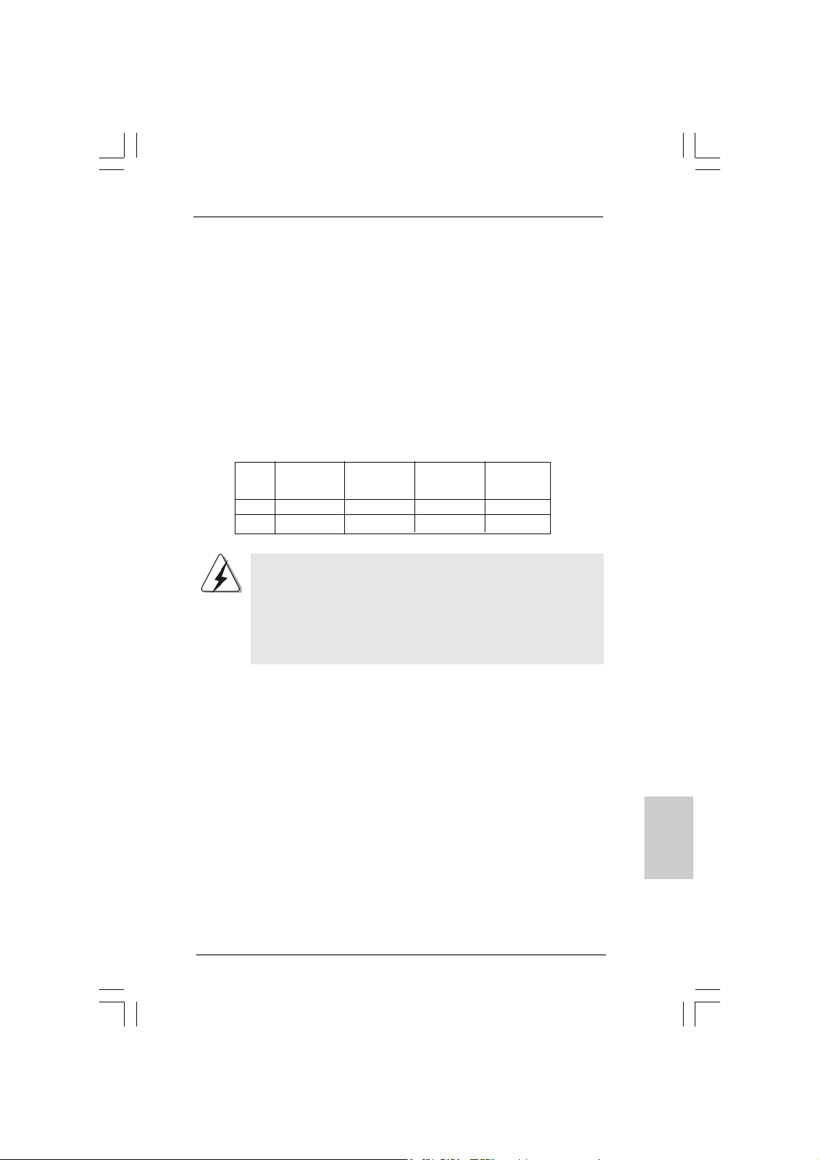
TABLE for Audio Output Connection
Audio Output Channels Front Speaker Rear Speaker Central / Bass Side Speaker
(No. 7) (No. 4) (No. 5) (No. 3)
2 V -- -- -4VV---6 VVV-8 VVVV
* To enable Multi-Streaming function, you need to connect a front panel audio cable to the front
panel audio header. After restarting your computer, you will find “Mixer” tool on your system.
Please select “Mixer ToolBox” , click “Enable playback multi-streaming”, and click
“ok”. Choose “2CH”, “4CH”, “6CH”, or “8CH” and then you are allowed to select “Realtek HDA
Primary output” to use Rear Speaker, Central/Bass, and Front Speaker, or select “Realtek HDA
Audio 2nd output” to use front panel audio.
ASRock 775Dual-VSTA Motherboard
EnglishEnglish
EnglishEnglish
English
33
3
33
Page 4
1. Introduction1. Introduction
1. Introduction
1. Introduction1. Introduction
Thank you for purchasing ASRock 775Dual-VSTA motherboard, a reliable motherboard produced under ASRock’s consistently stringent quality control. It delivers
excellent performance with robust design conforming to ASRock’s commitment to
quality and endurance.
This Quick Installation Guide contains introduction of the motherboard and step-bystep installation guide. More detailed information of the motherboard can be found in
the user manual presented in the Support CD.
Because the motherboard specifications and the BIOS software might
be updated, the content of this manual will be subject to change
without notice. In case any modifications of this manual occur, the
updated version will be available on ASRock website without further
notice. You may find the latest VGA cards and CPU support lists on
ASRock website as well.
ASRock website
1.1 Package Contents1.1 Package Contents
1.1 Package Contents
1.1 Package Contents1.1 Package Contents
ASRock 775Dual-VSTA Motherboard
(ATX Form Factor: 12.0-in x 9.6-in, 30.5 cm x 24.4 cm)
ASRock 775Dual-VSTA Quick Installation Guide
ASRock 775Dual-VSTA Support CD
(including LGA 775 CPU Installation Live Demo)
One 80-conductor Ultra ATA 66/100/133 IDE Ribbon Cable
One Ribbon Cable for a 3.5-in Floppy Drive
One Serial ATA (SATA) Cable (Optional)
One Serial ATA (SATA) HDD Power Cable (Optional)
One HDMI_SPDIF Cable (Optional)
One HD 8CH I/O Panel Shield
http://www.asrock.com
English
EnglishEnglish
EnglishEnglish
44
4
44
ASRock 775Dual-VSTA Motherboard
Page 5
1.21.2
SpecificationsSpecifications
1.2
Specifications
1.21.2
SpecificationsSpecifications
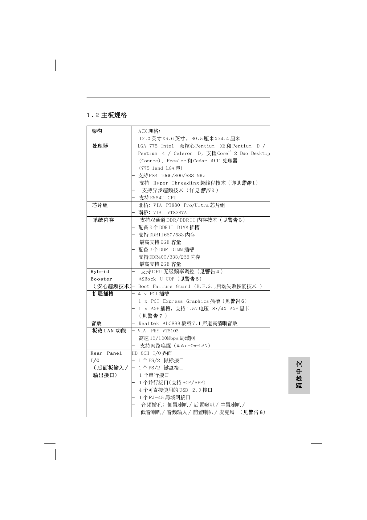
Platform - ATX Form Factor: 12.0-in x 9.6-in, 30.5 cm x 24.4 cm
CPU - LGA 775 for Intel® Dual Core Pentium® XE and Pentium® D /
Pentium® 4 / Celeron® D, supporting CoreTM 2 Duo De sktop
(Conroe), Presler and Cedar Mill processors
(in 775-land LGA package)
- FSB 1066/800/533 MHz
- Supports Hyper-Threading Technology (see CAUTION 1)
- Supports Untied Overclocking Technology (see CAUTION 2)
- Supports EM64T CPU
Chipset - Northbridge: VIA® PT880 Pro/Ultra chipset
- Southbridge: VIA® VT8237A
Memory - Dual Channel DDR/DDRII Memory T echnology
(see CAUTION 3)
- 2 x DDRII DIMM slots
- Support DDRII667/533
- Max. capacity: 2GB
- 2 x DDR DIMM slots
- Support DDR400/333/266
- Max. capacity: 2GB
Hybrid Booster - CPU Frequency Stepless Control (see CAUTION 4)
- ASRock U-COP (see CAUTION 5)
- Boot Failure Guard (B.F.G.)
Expansion Slot - 4 x PCI slots
- 1 x PCI Express Graphics slot (see CAUTION 6)
- 1 x AGP slot for 1.5V 8X/4X AGP card (see CAUTION 7)
Audio - Realtek ALC888 7.1 cha nnel audio CODEC with High
Definition audio
LAN - VIA® PHY VT6103
- Speed: 10/100 Ethernet
- Supports Wake-On-LAN
Rear Panel I/O HD 8CH I/O
- 1 x PS/2 Mouse Port
- 1 x PS/2 Keyboard Port
- 1 x Serial Port: COM1
- 1 x Parallel Port (ECP/EPP Support)
- 4 x Ready-to-Use USB 2.0 Ports
- 1 x RJ-45 Port
- Audio Jack: Side Speaker/Rear Speaker/Central Bass/Line
in/Front Speaker/Microphone (see CAUTION 8)
EnglishEnglish
EnglishEnglish
English
ASRock 775Dual-VSTA Motherboard
55
5
55
Page 6
English
EnglishEnglish
EnglishEnglish
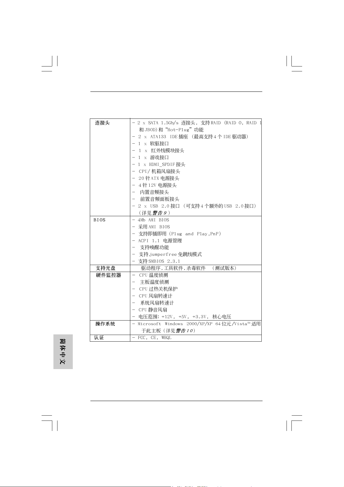
Connector - 2 x Serial ATA 1.5Gb/s connectors, support RAID (RAID 0,
RAID 1, and JBOD) and “Hot Plug” functions
- 2 x ATA133 IDE connector (supports 4 x IDE devices)
- 1 x Floppy connector
- 1 x IR header
- 1 x Game header
- 1 x HDMI_SPDIF header (HDMI_SPDIF1)
- CPU/Chassis FAN connector
- 20 pin ATX power connector
- 4 pin 12V power connector
- CD in header
- Front panel audio connector
- 2 x USB 2.0 headers (support 4 USB 2.0 ports)
(see CAUTION 9)
BIOS Feature - 4Mb AMI BIOS
- AMI Legal BIOS
- Supports “Plug and Play”
- ACPI 1.1 Compli ance Wake Up Events
- Supports jumperfree
- SMBIOS 2.3.1 Support
Support CD - Drivers, Utilities, AntiVirus Software (Trial Version)
Hardware - CPU Temperature Sensing
Monitor - Chassis Temperature Sensing
- CPU Overheat Shutdown to Protect CPU Life
- CPU Fan Tachometer
- Chassis Fan Tachometer
- CPU Quiet Fan
- Voltage Monitoring: +12V, +5V, +3.3V, Vcore
OS - Microsoft
(see CAUTION 10)
Certifications - FCC, CE, WHQL
®
Windows® 2000/XP/XP 64-bit/VistaTM compliant
66
6
66
ASRock 775Dual-VSTA Motherboard
Page 7
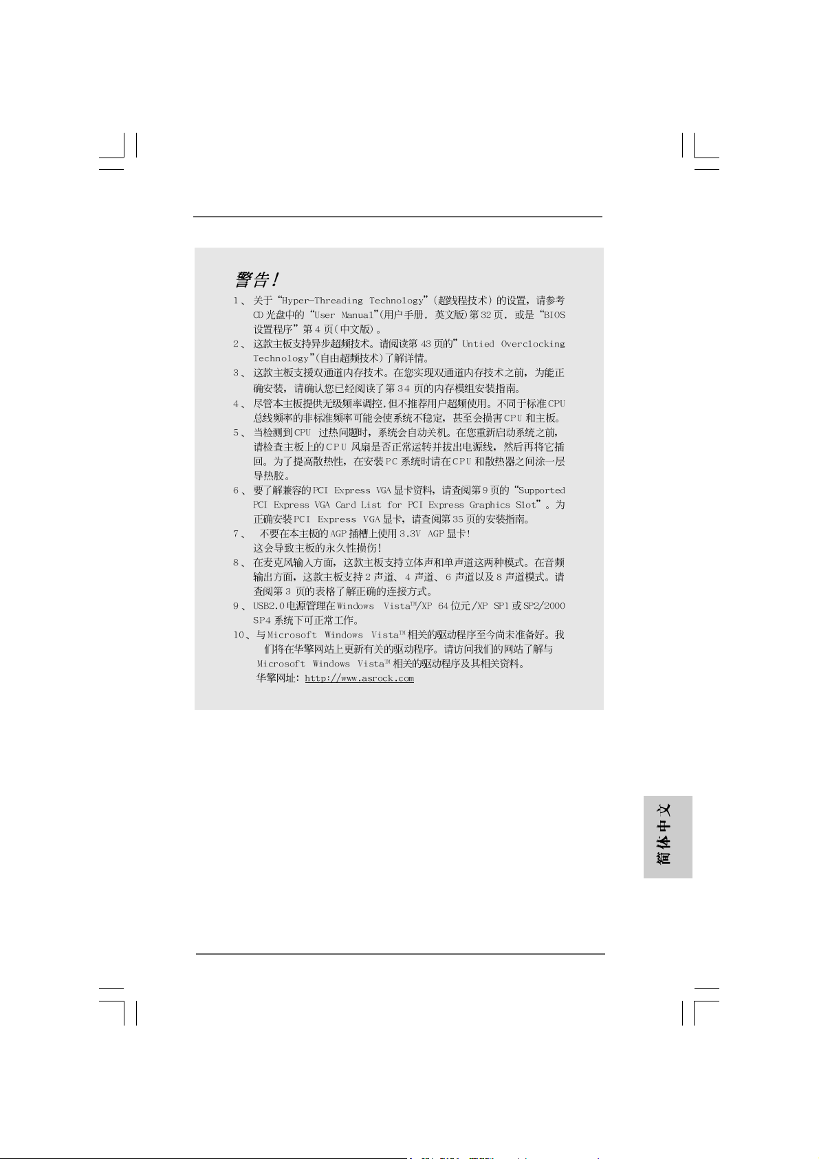
CAUTION!
1. About the setting of “Hyper Threading Te chnology”, please check page 32
of “User Manual” in the support CD.
2. This motherboard supports Untied Overclocking Technology. Please read
“Untied Overclocking Technology” on page 24 for details.
3. This motherboard supports Dual Cha nnel Me mory Technology. Before you
implement Dual Channel Memory Technology, make sure to read the
installation guide of memory modules on page 13 for proper installation.
4. Although this motherboard offers stepless control, it is not recommended
to perform over-clocking. Frequencies other than the recommended CPU
bus frequencies may cause the instability of the system or damage the
CPU.
5. While CPU overheat is detected, the system will automatically shutdown.
Before you resume the system, please check if the CPU fan on the
motherboard functions properly and unplug the power cord, then plug it
back again. To improve heat dissipation, remember to spray thermal
grease between the CPU a nd the he atsink when you install the PC syste m.
6. For the information of the compatible PCI Express VGA cards, please
refer to the “Supported PCI Express VGA Card List for PCI Express
Graphics Slot” on page 9. For the proper installation of PCI Express VGA
card, please refer to the installation guide on page 15.
7. Do NOT use a 3.3V AGP card on the AGP slot of this motherboard!
It may cause permanent damage!
8. For microphone input, this motherboard supports both stereo and mono
modes. For audio output, this motherboard supports 2-channel, 4-channel,
6-channel, and 8-channel modes. Please check the table on page 3 for
proper connection.
9. Power Management for USB 2.0 works fine under Microsoft® Windows
VistaTM / XP 64-bit / XP SP1 or SP2 / 2000 SP4.
10. Microsoft® Windows® VistaTM driver is not ready yet. We will update it to our
website in the future. Please visit our website for Microsoft® Windows® Vista
driver and related information.
ASRock website http://www.asrock.com
®
TM
ASRock 775Dual-VSTA Motherboard
EnglishEnglish
EnglishEnglish
English
77
7
77
Page 8
1.31.3
Minimum Hardware RMinimum Hardware R
1.3
Minimum Hardware R
1.31.3
Minimum Hardware RMinimum Hardware R
TMTM
TM
TMTM
VistaVista
Vista
VistaVista
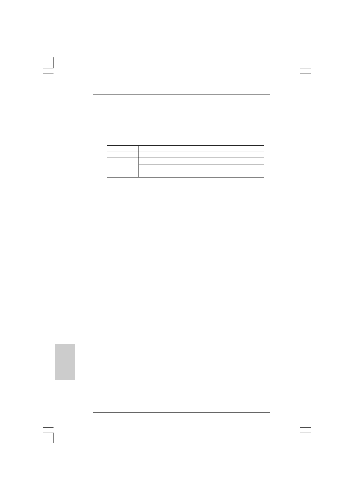
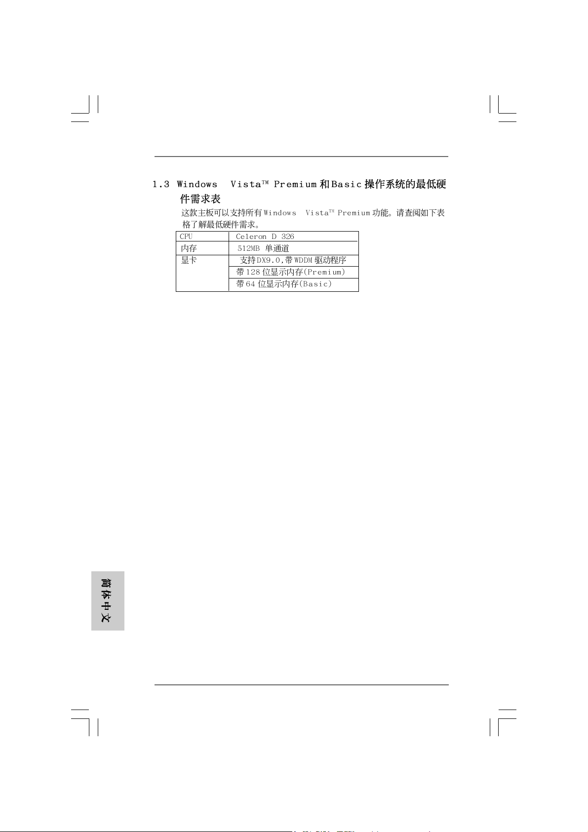
This motherboard can support all features in Windows® VistaTM Premium.
Please follow the below table for minimum hardware requirement.
CPU Celeron D 326
Memory 512MB Single Channel
VGA DX9.0 with WDDM Driver
Premium and Basic OS Premium and Basic OS
Premium and Basic OS
Premium and Basic OS Premium and Basic OS
with 128bit VGA memory (Premium)
with 64bit VGA memory (Basic)
equirement Tequirement T
equirement T
equirement Tequirement T
able for Wable for W
able for W
able for Wable for W
indowsindows
indows
indowsindows
®®
®
®®
English
EnglishEnglish
EnglishEnglish
88
8
88
ASRock 775Dual-VSTA Motherboard
Page 9
1.41.4
Supported PCI Express VGA Card List for PCISupported PCI Express VGA Card List for PCI
1.4
Supported PCI Express VGA Card List for PCI
1.41.4
Supported PCI Express VGA Card List for PCISupported PCI Express VGA Card List for PCI
Express Graphics SlotExpress Graphics Slot
Express Graphics Slot
Express Graphics SlotExpress Graphics Slot
(for Windows® 2000/XP/XP 64-bit/VistaTM)
Graphics Chip Model Name
Vendor
n-VIDIA ASUS Extreme N6200GE/TD
ASUS Extreme N6200TC256/TD
ASUS Extreme N6800GT
ASUS Extreme N6800/TD
ALBATRON PC6600GT
GIGABYTE GV -NX66128D
Inno3D GeFORCE 6600 LE
LEADTEK PX6200 TC/TDH
MSI PCX 5750-TD128E
SPARKLE GeFORCE 6200TC
A T I ASUS Extreme AX700PRO/TVD
ABIT RX600XT-PCIE
GECUBE Radeon X850XT 256M
For the latest updates of the supported PCI Express VGA card list for PCI
Express Graphics slot, please visit ASRock website for details.
ASRock website:
http://www.asrock.com/support/index.htm
ASRock 775Dual-VSTA Motherboard
EnglishEnglish
EnglishEnglish
English
99
9
99
Page 10
2.2.
InstallationInstallation
2.
Installation
2.2.
InstallationInstallation
Pre-installation PrecautionsPre-installation Precautions
Pre-installation Precautions
Pre-installation PrecautionsPre-installation Precautions
Take note of the following precautions before you install motherboard components or change any motherboard settings.
1. Unplug the power cord from the wall socket before touching any
component. Failure to do so may cause severe damage to the
motherboard, peripherals, and/or components.
2. To avoid damaging the motherboard components due to static
electricity, NEVER place your motherboard directly on the carpet
or the like. Also remember to use a grounded wrist strap or touch
a safety grounded object before you handle components.
3. Hold components by the edges and do not touch the ICs.
4. Whenever you uninstall any component, place it on a grounded
antstatic pad or in the bag that comes with the component.
5. When placing screws into the screw holes to secure the
motherboard to the chassis, please do not over-tighten the
screws! Doing so may damage the motherboard.
2.12.1
CPU InstallationCPU Installation
2.1
CPU Installation
2.12.1
CPU InstallationCPU Installation
For the installation of Intel 775-LAND CPU,
please follow the steps below.
English
EnglishEnglish
EnglishEnglish
1010
10
1010
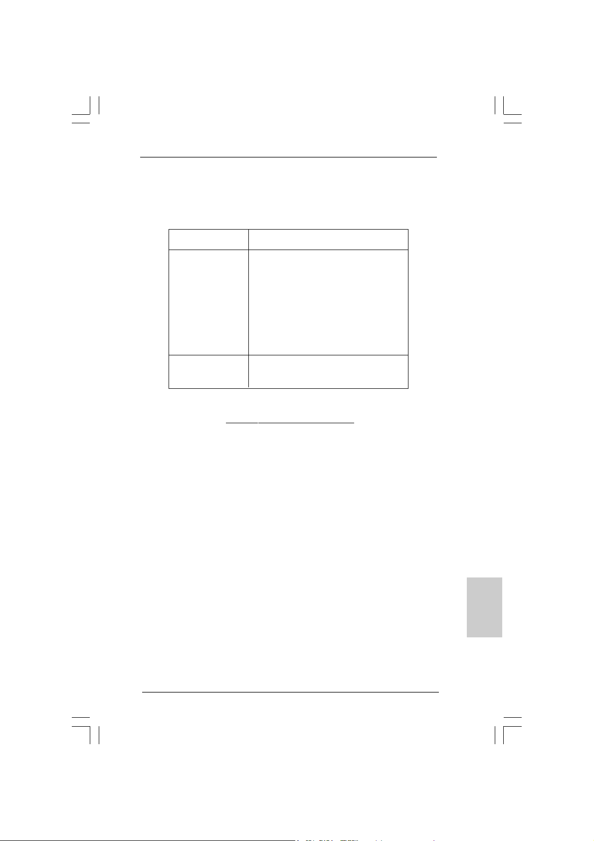
775-Pin Socket Overview
Before you insert the 775-LAND CPU into the socket, please check if
the CPU surface is unclean or if there is any bent pin on the socket.
Do not force to insert the CPU into the socket if above situation is
found. Otherwise, the CPU will be seriously damaged.
ASRock 775Dual-VSTA Motherboard
Page 11
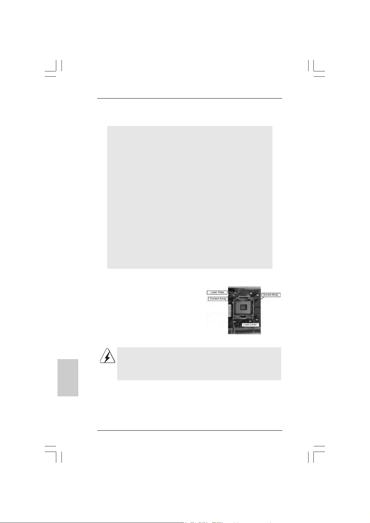
Step 1. Open the socket:
Step 1-1. Disengaging the lever by depressing
down and out on the hook to clear
retention tab.
Step 1-2. Rotate the load lever to fully open po-
sition at approximately 135 degrees.
Step 1-3. Rotate the load plate to fully open po-
sition at approximately 100 degrees.
Step 2. Insert the 775-LAND CPU:
Step 2-1. Hold the CPU by the edges where are
marked with black lines.
Step 2-2. Orient the CPU with IHS (Integrated
Heat Sink) up. Locate Pin1 and the two
orientation key notches.
Pin1
orientation
key notch
orientation
key notch
Pin1
alignment key
black line
black line
alignment key
775-LAND CPU
For proper inserting, please ensure to match the two orientation key
notches of the CPU with the two alignment keys of the socket.
Step 2-3. Carefully place the CPU into the socket
by using a purely vertical motion.
Step 2-4. Verify that the CPU is within the socket
and properly mated to the orient keys.
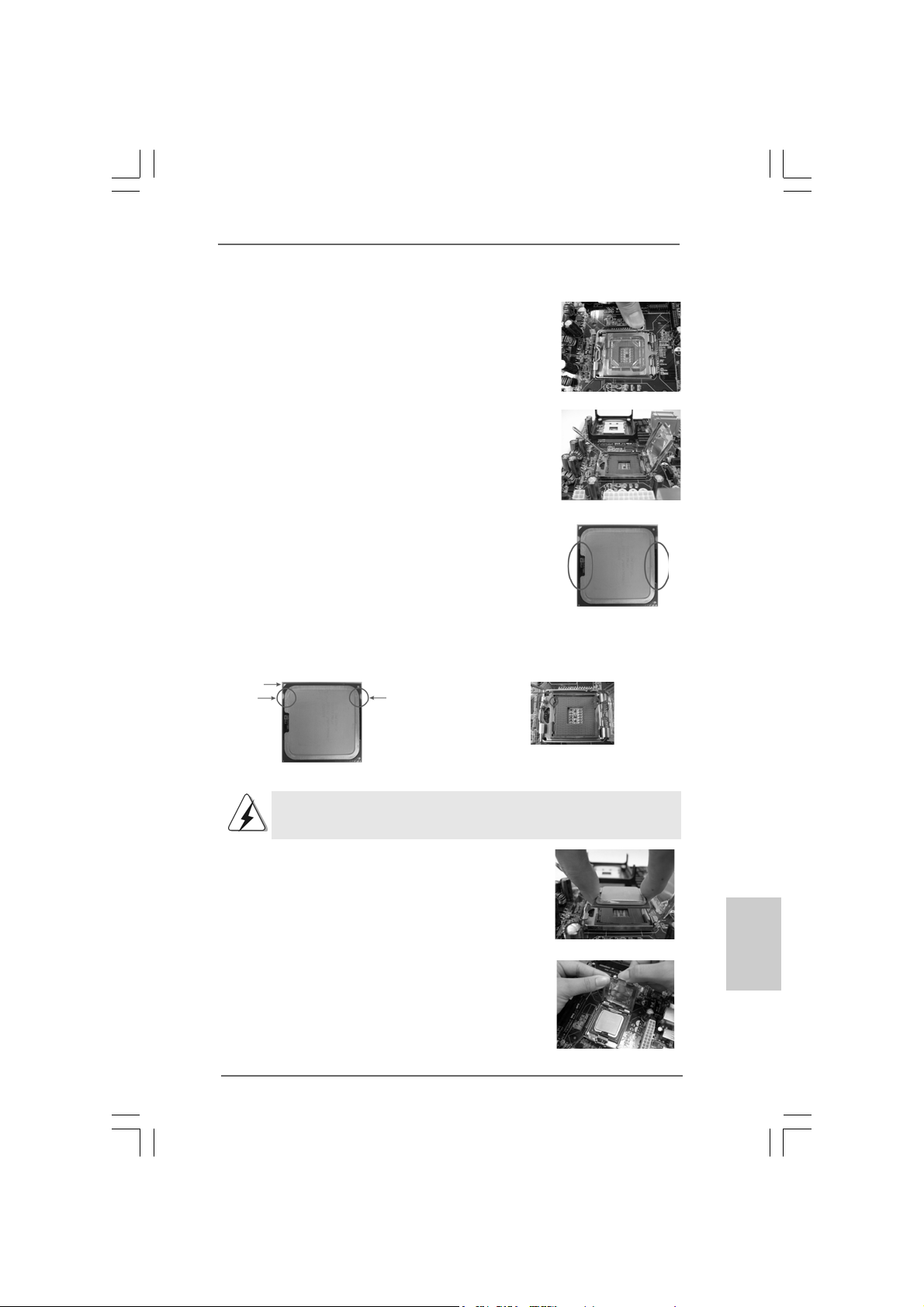
Step 3. Remove PnP Ca p (Pick a nd Place Ca p):
Use your left hand index finger and thumb to
support the load plate edge, engage PnP cap
with right hand thumb and peel the cap from the
socket while pressing on center of PnP cap to
assist in removal.
ASRock 775Dual-VSTA Motherboard
775-Pin Socket
1111
11
1111
EnglishEnglish
EnglishEnglish
English
Page 12
English
EnglishEnglish
EnglishEnglish
1. It is recommended to use the cap tab to handle and avoid kicking
off the PnP cap.
2. This cap must be placed if returning the motherboard for after
service.
Step 4. Close the socket:
Step 4-1. Rotate the load plate onto the IHS.
Step 4-2. While pressing down lightly on load
plate, engage the load lever.
Step 4-3. Secure load lever with load plate tab
under retention tab of load lever.
2.22.2
Installation of CPU Fan and HeatsinkInstallation of CPU Fan and Heatsink
2.2
Installation of CPU Fan and Heatsink
2.22.2
Installation of CPU Fan and HeatsinkInstallation of CPU Fan and Heatsink
For proper installation, please kindly refer to the instruction manuals of your CPU fan
and heatsink.
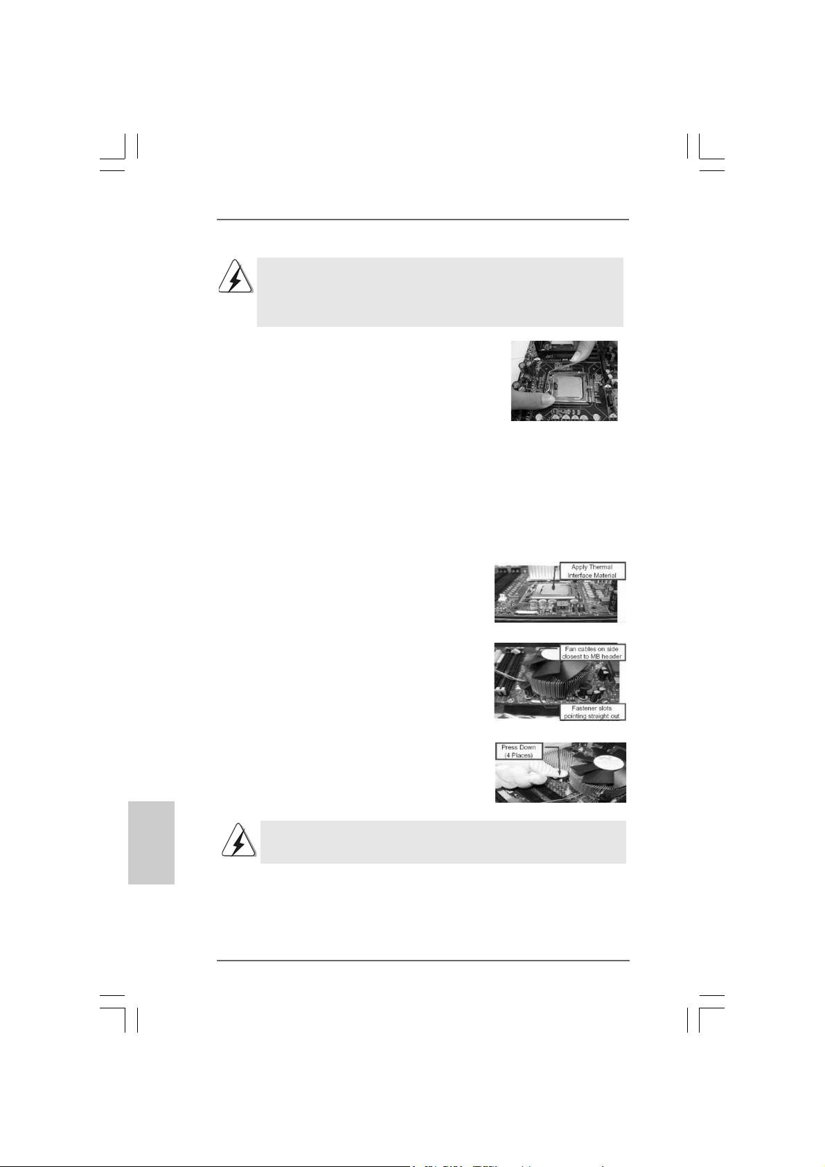
Below is an example to illustrate the installation of the heatsink for 775-LAND CPU.
Step 1. Apply thermal interface material onto center
of IHS on the socket surface.
Step 2. Place the heatsink onto the socket. Ensure
fan cables are oriented on side closest to the
CPU fan connector on the motherboard
(CPU_FAN1, see page 2, No. 5).
Step 3. Align fasteners with the motherboard
throughholes.
Step 4. Rotate the fastener clockwise, then press
down on fastener caps with thumb to install
and lock. Repeat with remaining fasteners.
If you press down the fasteners without rotating them clockwise, the heatsink cannot be
secured on the motherboard.
Step 5. Connect fan header with the CPU fan
connector on the motherboard.
Step 6. Secure excess cable with tie-wrap to ensure
cable does not interfere with fan operation or
1212
12
1212
contact other components.
ASRock 775Dual-VSTA Motherboard
Page 13
2.3 Installation of Memory Modules (DIMM)2.3 Installation of Memory Modules (DIMM)
2.3 Installation of Memory Modules (DIMM)
2.3 Installation of Memory Modules (DIMM)2.3 Installation of Memory Modules (DIMM)
775Dual-VSTA motherboard provides two 184-pin DDR (Double Data Rate)
DIMM slots and two 240-pin DDRII DIMM slots, and supports Dual Cha nnel Memory
Technology. For dual channel configuration, you always need to install identi-
cal (the same brand, speed, size and chip-type) DDR / DDRII DIMM pair in the
slots of the same color. In other words, you have to install identical DDRII DIMM
pair in Dual Channel A (DDRII_1 and DDRII_2; Yellow slots; see p.2 No.6) or
identical DDR DIMM pair in Dual Cha nnel B (DD R1 a nd DDR2; Blue slots; see p.
2 No.7), so that Dual Channel Memory Technology can be activated. You may
refer to the Dual Channel Memory Configuration Table below.
Dual Channel Memory Configurations
DDRII_1 DDR1 DDRII_2 DDR2
(Yellow Slot) (Blue Slot) (Yellow Slot) (Blue Slot)
(1) Populated - Populated (2) - Populated - Populated
1. It is not allowed to install a DDR memory module into DDRII slot or
a DDRII memory module into DDR slot; otherwise, this motherboard
and DIMM may be damaged.
2. It is not allowed to install both DDR and DDRII memory modules to
this motherboard at the same time; otherwise, this motherboard and
DIMM may be damaged.
ASRock 775Dual-VSTA Motherboard
1313
13
1313
EnglishEnglish
EnglishEnglish
English
Page 14
Installing a DIMMInstalling a DIMM
Installing a DIMM
Installing a DIMMInstalling a DIMM
Please make sure to disconnect power supply before adding or
removing DIMMs or the system components.
STEP 1: Unlock a DIMM slot by pressing the retaining clips outward.
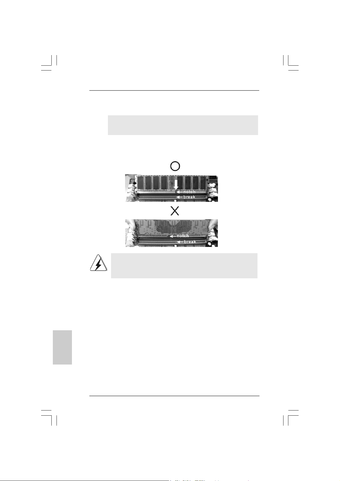
STEP 2: Align a DIMM on the slot such that the notch on the DIMM matches the
break on the slot.
The DIMM only fits in one correct orientation. It will cause permanent
damage to the motherboard and the DIMM if you force the DIMM into the
slot at incorrect orientation.
English
EnglishEnglish
EnglishEnglish
1414
14
1414
STEP 3: Firmly insert the DIMM into the slot until the retaining clips at both ends
fully snap back in place and the DIMM is properly seated.
ASRock 775Dual-VSTA Motherboard
Page 15
2.4 Expansion Slots (PCI, AGP, and PCI Express Graphics2.4 Expansion Slots (PCI, AGP, and PCI Express Graphics
2.4 Expansion Slots (PCI, AGP, and PCI Express Graphics
2.4 Expansion Slots (PCI, AGP, and PCI Express Graphics2.4 Expansion Slots (PCI, AGP, and PCI Express Graphics
Slots) Slots)
Slots)
Slots) Slots)
There are 4 PCI slots, 1 AGP slot, and 1 PCI Express Graphics slot on 775Dual-VSTA
motherboard.
PCI slots: PCI slots are used to install expansion cards that have the 32-bit PCI
interface.
AGP slot: The AGP slot is used to install a graphics card. The ASRock AGP slot has
a special design of clasp that can securely fasten the inserted graphics
card. AGP slot is used to install AGP expansion cards.
Please do NOT use a 3.3V AGP card on the AGP slot of this motherboard!
It may cause permanent damage! For the voltage information of your
AGP card, please check with the AGP card vendors.
PCI Express Graphics slot:
PCI Express Graphics slot is used to install PCI Express expa nsion cards.
For the information of the compatible PCI Express VGA cards, please
refer to the “Supported PCI Express VGA Card List for PCI Express
Graphics Slot” on page 9.
Installing an expansion cardInstalling an expansion card
Installing an expansion card
Installing an expansion cardInstalling an expansion card
Step 1. Before installing the expansion card, please make sure that the power
supply is switched off or the power cord is unplugged. Please read the
documentation of the expansion card and make necessary hardware
settings for the card before you start the installation.
Step 2. Remove the system unit cover (if your motherboard is already installed in a
chassis).
Step 3. Remove the bracket facing the slot that you intend to use. Keep the screws
for later use.
Step 4. Align the card connector with the slot and press firmly until the card is
completely seated on the slot.
Step 5. Fasten the card to the chassis with screws.
Step 6. Replace the system cover.
ASRock 775Dual-VSTA Motherboard
1515
15
1515
EnglishEnglish
EnglishEnglish
English
Page 16
2.5 Surround Display Feature2.5 Surround Display Feature
2.5 Surround Display Feature
2.5 Surround Display Feature2.5 Surround Display Feature
Thanks to ASRock patented PCI Express Graphics Technology, this motherboard
supports Surround Display upgrade. With the external add-on AGP VGA card and
PCI Express VGA card, you can easily enjoy the benefits of Surround Display
feature. For the detailed instruction, please refer to the document at the following
path in the Support CD: ..\ Surround Display Information
2.6 Jumpers Setup2.6 Jumpers Setup
2.6 Jumpers Setup
2.6 Jumpers Setup2.6 Jumpers Setup
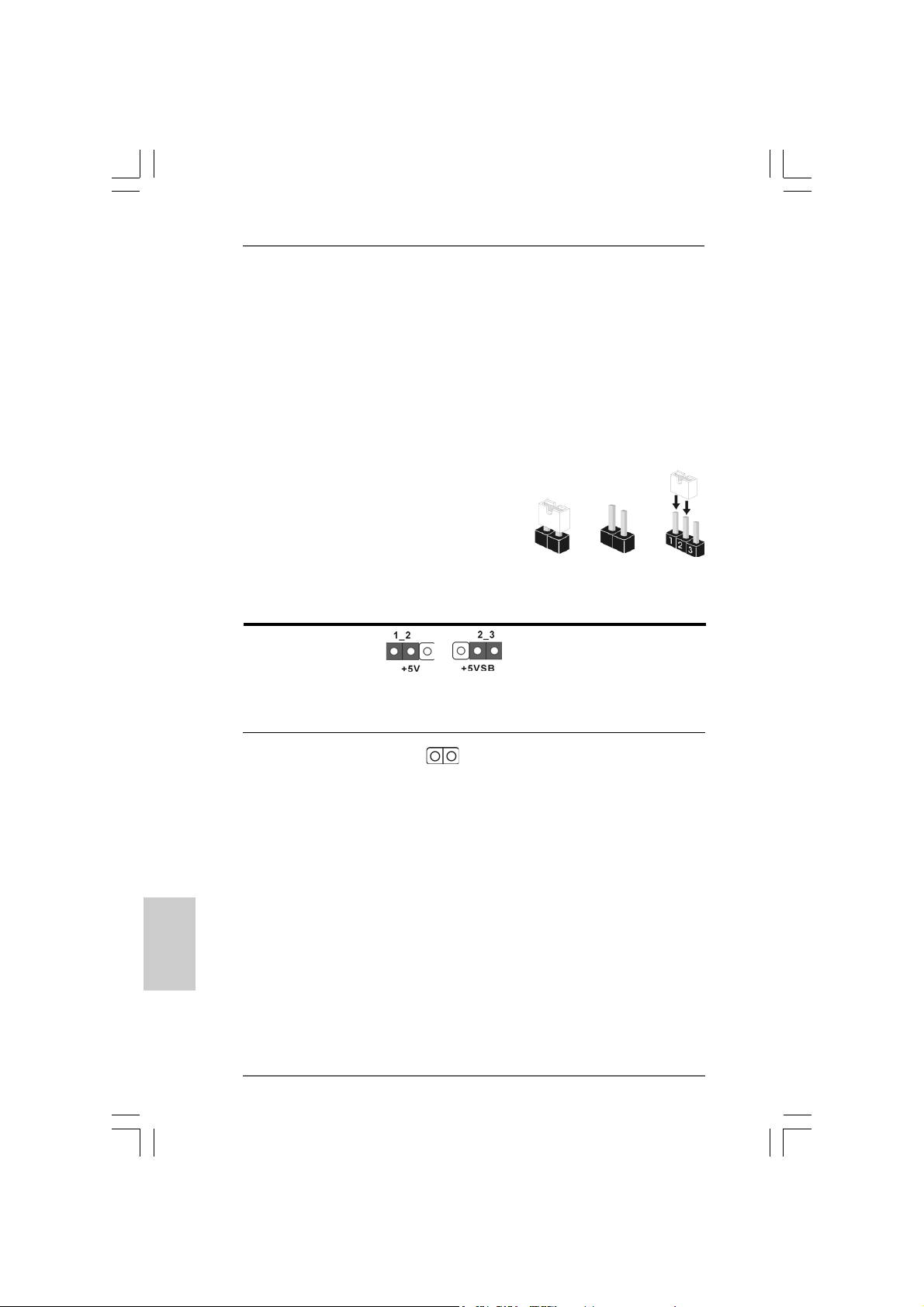
The illustration shows how jumpers are
setup. When the jumper cap is placed on
pins, the jumper is “Short”. If no jumper cap
is placed on pins, the jumper is “Open”. The
illustration shows a 3-pin jumper whose pin1
and pin2 are “Short” when jumper cap is
placed on these 2 pins.
Jumper Setting
PS2_USB_PWR1 Short pin2, pin3 to enable
(see p.2, No. 1) +5VSB (standby) for PS/2
Note: To select +5VSB, it requires 2 Amp and higher standby current provided
by power supply.
Short
or USB wake up events.
Open
English
EnglishEnglish
EnglishEnglish
1616
16
1616
Clear CMOS
(CLRCMOS1, 2-pin jumper)
(see p.2, No. 19)
Note: CLRCMOS1 allows you to clear the data in CMOS. The data in CMOS includes
system setup information such as system password, date, time, and system
setup parameters. To clear and reset the system parameters to default setup,
please turn off the computer and unplug the power cord from the power
supply. After waiting for 15 seconds, use a jumper cap to short 2 pins on
CLRCMOS1 for 5 seconds.
ASRock 775Dual-VSTA Motherboard
2-pin jumper
Page 17
2.7 Onboard Headers and Connectors2.7 Onboard Headers and Connectors
2.7 Onboard Headers and Connectors
2.7 Onboard Headers and Connectors2.7 Onboard Headers and Connectors
Onboard headers and connectors are NOT jumpers. Do NOT place
jumper caps over these headers and connectors. Placing jumper caps
over the headers and connectors will cause permanent damage of the
motherboard!
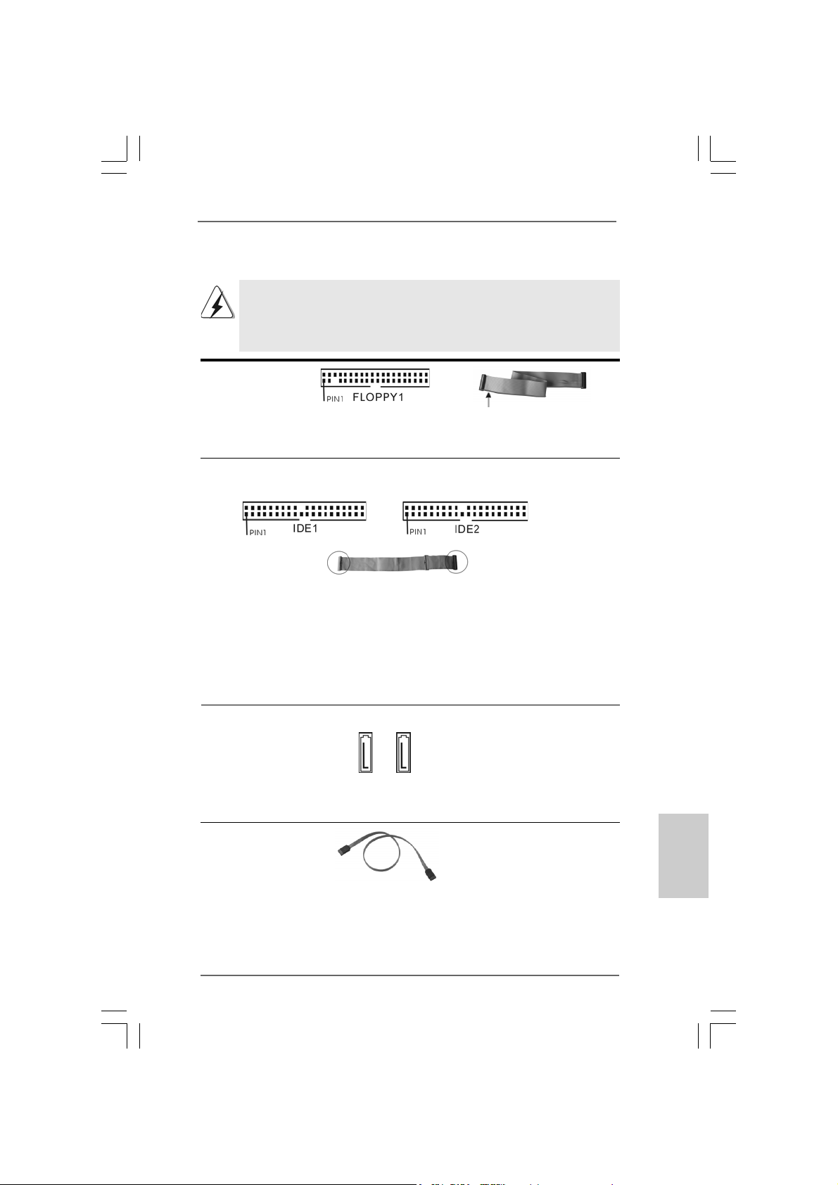
F DD Connector
(33-pin FLOPPY1)
(see p.2 No. 21)
the red-striped side to Pin1
Note: Make sure the red-striped side of the cable is plugged into Pin1 side of the
connector.
Primary IDE Connector (Blue) Secondary IDE Connector (Black)
(39-pin IDE1, see p.2 No. 9) (39-pin IDE2, see p.2 No. 10)
connect the blue end
to the motherboard
80-conductor ATA 66/100/133 cable
connect the black end
to the IDE devices
Note: If you use only one IDE device on this motherboard, please set the IDE
device as “Master”. Please refer to the instruction of your IDE device vendor
for the details. Besides, to optimize compatibility and performance, please
connect your hard disk drive to the primary IDE connector (IDE1, blue) and
CD-ROM to the secondary IDE connector (IDE2, black).
Serial ATA Connectors These two Serial ATA (SATA)
(SAT A1: see p.2 No. 12) connectors support SATA data
(SAT A2: see p.2 No. 1 1) cables for internal storage
devices. The current SATA
SAT A1 SATA2
interface allows up to 1.5 Gb/s
data transfer rate.
Serial A TA (SAT A) Either end of the SATA data cable
Data Cable can be connected to the SATA
hard disk or the SA TA connector
on the motherboard.
EnglishEnglish
EnglishEnglish
English
ASRock 775Dual-VSTA Motherboard
1717
17
1717
Page 18
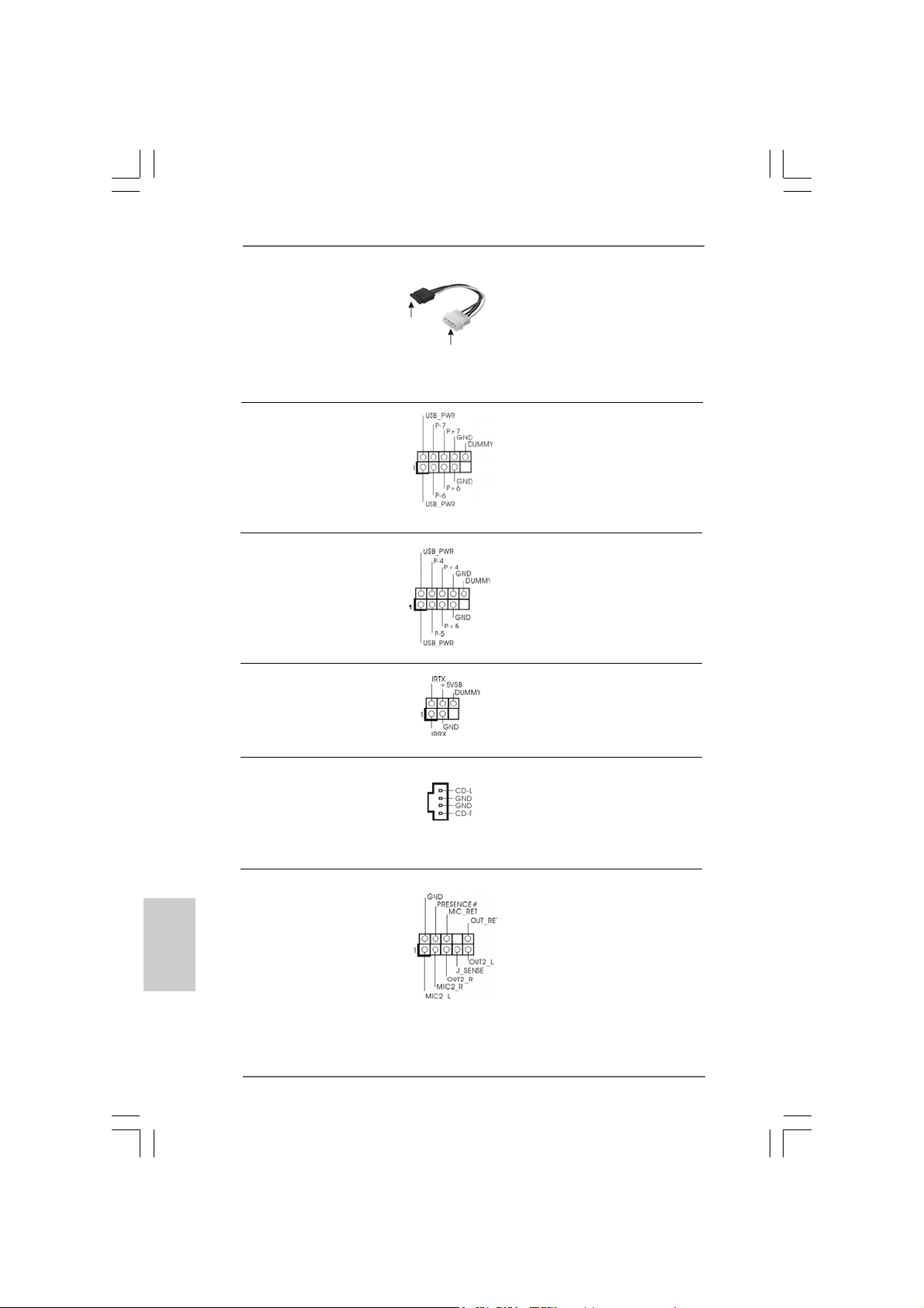
Serial ATA (SATA) Please connect the black end of
Power Cable SATA power cable to the power
(Optional) connector on the drive. Then
connect to the SAT A
HDD power connector
connect to the
power supply
connect the white end of SATA
power cable to the power
connector of the power supply.
USB 2.0 Header HD 8CH I/O provides you
(9-pin USB67) 4 ready-to-use USB 2.0 ports on
(see p.2, No. 20) the rear panel. If the rear USB
ports are not sufficient, this
USB 2.0 header is available to
support 2 extra USB 2.0 ports.
USB 2.0 Header HD 8CH I/O provides you
(9-pin USB45) 4 ready-to-use USB 2.0 ports on
(see p.2, No. 18) the rear panel. If the rear USB
ports are not sufficient, this
USB 2.0 header is available to
support 2 extra USB 2.0 ports.
Infrared Module Header This header supports an optional
(5-pin IR1) wireless transmitting and
(see p.2, No. 27) receiving infrared module.
English
EnglishEnglish
EnglishEnglish
1818
18
1818
Internal Audio Connector This connector allows you
(4-pin CD1) to receive stereo audio input
(CD1: see p.2, No. 28) from sound sources such as
CD1
a CD-ROM, D VD-ROM, TV
tuner card, or MPEG card.
Front Panel Audio Header This is an interface for the front
(9-pin HD_AUDIO1) panel audio cable that allows
(see p.2, No. 24) convenient connection and
control of audio devices.
ASRock 775Dual-VSTA Motherboard
Page 19
1. High Definition Audio supports Jack Sensing, but the panel wire on the
chassis must support HDA to function correctly. Please follow the
instruction in our manual and chassis manual to install your system.
2. If you use AC’97 audio panel, please install it to the front panel audio
header as below:
A. Connect Mic_IN (MIC) to MIC2_L.
B. Connect Audio_R (RIN) to OUT2_R and Audio_L (LIN) to OUT2_L.
C. Connect Ground (GND) to Ground (GND).
D. MIC_RET and OUT_RET are for HD audio panel only. You don’t
need to connect them for AC’97 audio panel.
E. Enter BIOS Setup Utility. Enter Advanced Settings, and then select
Chipset Configuration. Set the Front Panel Control option from
[Auto] to [Enabled].
F. Enter Windows system. Click the icon on the lower right hand
taskbar to enter Realtek HD Audio Manager. Click “Audio I/O”,
select “Connector Settings” , choose “Disable front
panel jack detection”, and save the change by clicking “OK”.
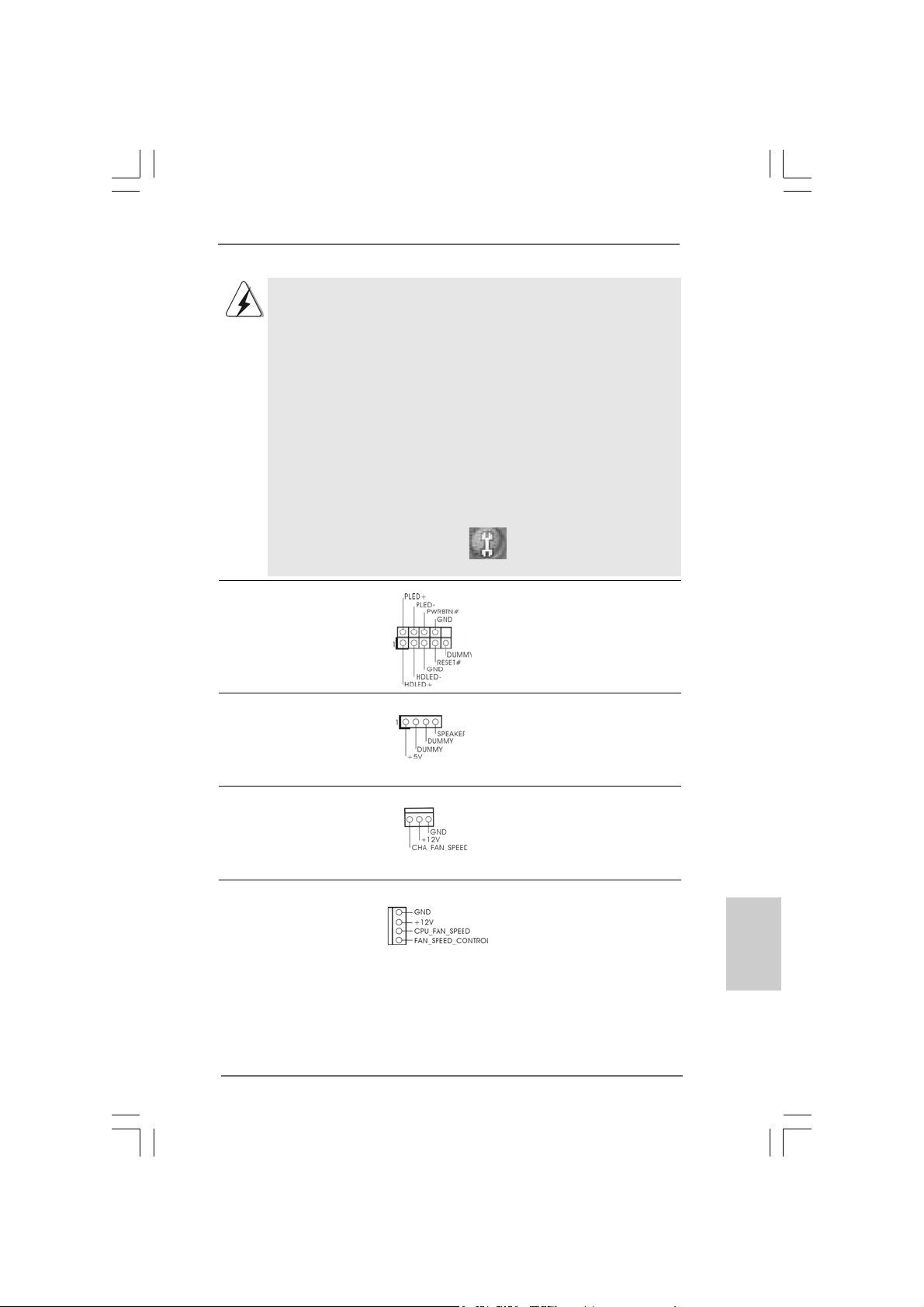
System Panel Header This header accommodates
(9-pin PANEL1) several system front panel
(see p.2, No. 13) functions.
Chassis Speaker Header Please connect the chassis
(4-pin SPEAKER 1) speaker to this header.
(see p.2, No. 14)
Chassis Fan Connector Please connect the chassis fan
(3-pin CHA_FAN1) cable to this connector and
(see p.2, No. 15) match the black wire to the
ground pin.
CPU Fan Connector Please connect the CPU fan
(4-pin CPU_FAN1) cable to this connector and
(see p.2, No. 5) match the black wire to the
ground pin.
ASRock 775Dual-VSTA Motherboard
1919
19
1919
EnglishEnglish
EnglishEnglish
English
Page 20
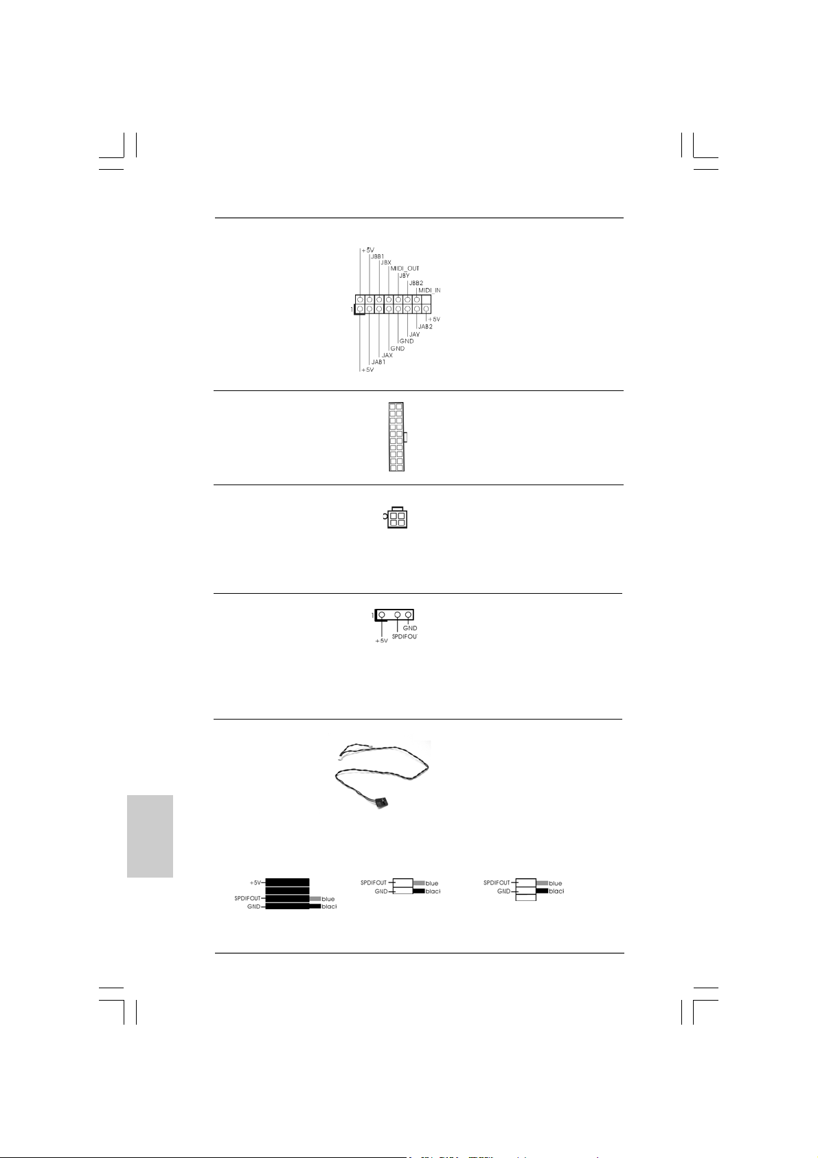
Game Conne ctor Connect a Game cable to this
(15-pin GAME1) connector if the Game port
(see p.2, No. 22) bracket is installed.
ATX Power Connector Please connect an ATX power
(20-pin ATXPW R1) supply to this connector.
(see p.2, No. 29)
ATX 12V Connector Please note that it is necessary
(4-pin A TX12V1) to connect a power supply with
(see p.2, No. 2) ATX 12V plug to this connector
so that it can provides sufficient
power. Failing to do so will cause
the failure to power up.
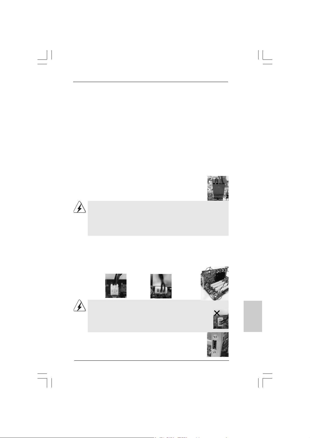
HDMI_SPDIF Header HDMI_SPDIF header, providing
(3-pin HDMI_SPDIF1) SPDIF audio output to HDMI V GA
(see p.2 No. 23) card, allows the system to
connect HDMI Digital TV/
projector/LCD devices. Please
connect the HDMI connector of
HDMI VGA card to this header.
English
EnglishEnglish
EnglishEnglish
2020
20
2020
HDMI_SPDIF Cable Please connect the black end (A)
(Optional) of HDMI_SPDIF cable to the
B
C
HDMI_SPDIF header on the
motherboard. Then connect the
A
white end (B or C) of
HDMI_SPDIF cable to the HDMI
connector of HDMI VGA card.
A. black end B. white end (2-pin) C. white end (3-pin)
ASRock 775Dual-VSTA Motherboard
Page 21
2.8 HDMI_SPDIF Header Connection Guide2.8 HDMI_SPDIF Header Connection Guide
2.8 HDMI_SPDIF Header Connection Guide
2.8 HDMI_SPDIF Header Connection Guide2.8 HDMI_SPDIF Header Connection Guide
HDMI (High-Definition Multi-media Interfa ce) is an all-digital audio/video specification,
which provides an interface between any compatible digital audio/video source,
such as a set-top box, DVD player, A/V receiver and a compatible digital audio or
video monitor, such as a digital television (DTV). A complete HDMI system requires a
HDMI V GA card and a HDMI rea dy motherboard with a HDMI_SPDIF header connected.
This motherboard is equipped with a HDMI_SPDIF header, which provides SPDIF
audio output to HDMI VGA card, allows the system to connect HDMI Digital TV/
projector/LCD devices. To use HDMI function on this motherboard, please carefully
follow the below steps.
•
Step 1. Install the HDMI VGA card to the PCI Express Graphics slot on this
motherboard. For the proper installation of HDMI VGA card, please refer to
the installation guide on page 15.
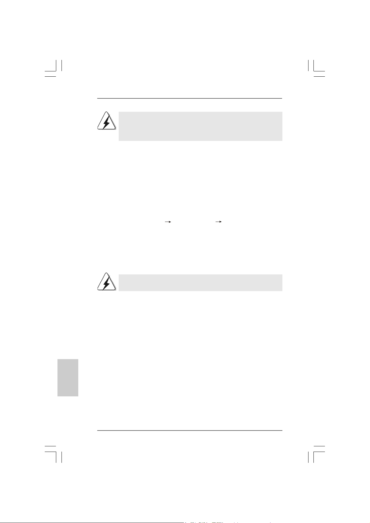
Step 2. Connect the black end (A) of HDMI_SPDIF cable to the
HDMI_SPDIF header (HDMI_SPDIF1, yellow , see page 2, No.
23) on the motherboard.
Make sure to correctly connect the HDMI_SPDIF cable to the motherboard and the
HDMI VGA card according to the same pin definition. For the pin definition of
HDMI_SPDIF header and HDMI_SPDIF ca ble connectors, ple ase refer to page 20. For
the pin definition of HDMI connectors, please refer to the user manual of HDMI VGA
card vendor. Incorrect connection may cause permanent damage to this motherboard
and the HDMI VGA card.
Step 3. Connect the white end (B or C) of HDMI_SPDIF cable to the HDMI connector
of HDMI VGA card. (There are two white ends (2-pin and 3-pin) on HDMI_
_SPDIF cable. Please choose the appropriate white end according to the
HDMI connector of the HDMI VGA card you install. Currently, the HDMI connector of HDMI VGA card with ATI chip is 3-pin (C), and the HDMI connector of HDMI VGA card with other vendor’s chip is 2-pin (B).)
white end
(2-pin) (B)
Please do not connect the white end of HDMI_SPDIF cable to the wrong connector
of HDMI VGA card or other VGA card. Otherwise, the motherboard and the
VGA card may be damaged. For example, this picture shows the wrong
example of connecting HDMI_SPDIF cable to the fan connector of PCI
Express VGA card. Please refer to the VGA card user manual for
connector usage in advance.
white end
(3-pin) (C)
Step 4. Connect the HDMI output connector to HDMI device, such as
HDTV. Please refer tothe user manual of HDTV and HDMI
VGA card vendor for detailed connection procedures.
Step 5. Install HDMI VGA card driver to your system.
ASRock 775Dual-VSTA Motherboard
2121
21
2121
EnglishEnglish
EnglishEnglish
English
Page 22
2.9 Serial A2.9 Serial A
2.9 Serial A
2.9 Serial A2.9 Serial A
This motherboard adopts VIA® VT8237A southbridge chipset that supports Serial
ATA (SATA) hard disks and RAID (RAID 0, RAID 1, and JBOD) functions. You may
install SATA hard disks on this motherboard for internal storage devices. This
section will guide you to install the SATA hard disks.
STEP 1: Install the SATA hard disks into the drive bays of your chassis.
STEP 2: Connect the SATA power cable to the SATA hard disk.
STEP 3: Connect one end of the SATA data cable to the motherboard’s SATA
STEP 4: Connect the other end of the SATA data cable to the SATA hard disk.
TT
T
TT
connector.
A (SAA (SA
TT
A) Hard Disks InstallationA) Hard Disks Installation
A (SA
T
A) Hard Disks Installation
A (SAA (SA
TT
A) Hard Disks InstallationA) Hard Disks Installation
English
EnglishEnglish
EnglishEnglish
2.10 Hot Plug and Hot Swap F2.10 Hot Plug and Hot Swap F
2.10 Hot Plug and Hot Swap F
2.10 Hot Plug and Hot Swap F2.10 Hot Plug and Hot Swap F
775Dual-VSTA motherboard supports Hot Plug and Hot Swap functions
for SATA Devices.
NOTE
What is Hot Plug Function?
If the SATA HDDs are NOT set for RAID configuration, it is called “Hot
Plug” for the action to insert and remove the SATA HDDs while the system
is still power-on and in working condition.
However, please note that it cannot perform Hot Plug if the OS has been
installed into the SATA HDD.
What is Hot Swap Function?
If SATA HDDs are built as RAID1 then it is called “Hot Swap” for the action
to insert and remove the SATA HDDs while the system is still power-on
and in working condition.
unctions for SAunctions for SA
unctions for SA
unctions for SAunctions for SA
TT
A HDDsA HDDs
T
A HDDs
TT
A HDDsA HDDs
2222
22
2222
ASRock 775Dual-VSTA Motherboard
Page 23

®®
®
2.112.11
Installing WindowsInstalling Windows
2.11
Installing Windows
2.112.11
Installing WindowsInstalling Windows
With RAID FunctionsWith RAID Functions
With RAID Functions
With RAID FunctionsWith RAID Functions
If you want to install Windows® 2000 / Windows® XP / Windows® XP-64bit / Windows
VistaTM OS on your SATA HDDs with RAID functions, please follow the below steps.
STEP 1: Make a SATA Driver Diskette.
A. Insert the ASRock Support CD into your optical drive to boot your system.
B. During POST at the beginning of system boot-up, press <F11> key, and then a
window for boot devices selection ap pears. Please select CD-ROM as the boot
device.
C. When you see the message on the screen, “Do you want to generate Serial
ATA driver diskette [YN]?”, press <Y>.
D. Then you will see these messages,
Please insert a diskette into the floppy drive.
WARNING! Formatting the floppy diskette will
lose ALL data in it!
Start to format and copy files [YN]?
Please insert a floppy diskette into the floppy drive, and press <Y>.
E. The system will start to format the floppy diskette and copy SATA drivers into
the floppy diskette.
STEP 2: Use “RAID Installation Guide” to set RAID configuration.
Before you start to configure the RAID function, you need to check theinstallation
guide in the Support CD for proper configuration. Please refer to the document in the
Support CD, “Guide to SATA Hard Disk s Installation and RAID Configuration”, which is
located in the folder at the following path: .. \ RAID Installation Guide
STEP 3: Install Windows® 2000 / Windows® XP / Windows® XP-64bit /
Windows® VistaTM OS on your system.
After making a SATA driver diskette and using “RAID Installation Guide” to set RAID
configuration, you can start to installWindows® 2000 / Windows® XP / Windows® XP64bit / Windows® VistaTM on your system.
®®
2000 / XP / XP 64-bit / Vista 2000 / XP / XP 64-bit / Vista
2000 / XP / XP 64-bit / Vista
2000 / XP / XP 64-bit / Vista 2000 / XP / XP 64-bit / Vista
TM
TMTM
TMTM
®
After the installation of Windows® 2000 / Windows® XP / Windows® XP-64bit /
Windows® VistaTM OS, if you want to manage RAID functions, you are allowed
to use both “RAID Installation Guide” and “VIA RAID Tool Information” for RAID
configuration. Please refer to the document in the Support CD, “Guide to SATA
Hard Disks Installation and RAID Configuration”, which is located in the folder at
the following path: .. \ RAID Installation Guide and the document in the support CD, “Guide to VIA RAID Tool”, which is located in the folder at the following
path: .. \ VIA RAID Tool Information
ASRock 775Dual-VSTA Motherboard
2323
23
2323
EnglishEnglish
EnglishEnglish
English
Page 24
If you want to use “VIA RAID Tool Information” in Windows® environment,
please install SATA drivers from the Support CD again so that “VIA RAID
Tool Information” will be installed to your system as well.
English
EnglishEnglish
EnglishEnglish
®®
®
2.122.12
Installing WindowsInstalling Windows
2.12
Installing Windows
2.122.12
Installing WindowsInstalling Windows
Without RAID FunctionsWithout RAID Functions
Without RAID Functions
Without RAID FunctionsWithout RAID Functions
If you want to install Windows® 2000 / Windows® XP / Windows® XP-64bit / Windows
VistaTM on your SATA HDDs without RAID functions or you want to install Windows
2000 / Windows® XP / Windows® XP-64bit / Windows® VistaTM on your IDE HDDs
instead of SATA HDDs, please follow the below steps.
STEP 1: Set Up BIOS.
A. Enter BIOS SETUP UTILITY Advanced screen IDE Configuration.
B. Set the “Onboard SATA Operation Mode” option from [RAID] to [non-RAID].
STEP 2: Install Windows® 2000 / Windows® XP / Windows® XP-64bit /
Windows® VistaTM OS on your system.
After setting up BIOS, you can start to install Windows® 2000 / Windows® XP /
Windows® XP-64bit / Windows® VistaTM on your system.
If you don’t want to set up RAID functions, there is no need to make a
SATA driver diskette.
2.132.13
Untied Overclocking TUntied Overclocking T
2.13
Untied Overclocking T
2.132.13
Untied Overclocking TUntied Overclocking T
This motherboard supports Untied Overclocking Technology, which means during
overclocking, FSB enjoys better margin due to fixed AGP / PCI / PCIE bus. You may
set “CPU Host Frequency” option of BIOS setup to [Auto], which will show you the
actual CPU host frequency in the following ite m. Therefore, CPU FSB is untied during
overclocking, but AGP / PCI / PCIE bus is in the fixed mode so that FSB can operate
under a more stable overclocking environment.
®®
2000 / XP / XP 64-bit / Vista 2000 / XP / XP 64-bit / Vista
2000 / XP / XP 64-bit / Vista
2000 / XP / XP 64-bit / Vista 2000 / XP / XP 64-bit / Vista
echnologyechnology
echnology
echnologyechnology
TMTM
TM
TMTM
®
®
2424
24
2424
ASRock 775Dual-VSTA Motherboard
Page 25
3. BIOS Information3. BIOS Information
3. BIOS Information
3. BIOS Information3. BIOS Information
The Flash Memory on the motherboard stores BIOS Setup Utility. When you start up
the computer, please press <F2> during the Power-On-Self-Test (POST) to enter
BIOS Setup utility; otherwise, POST continues with its test routines. If you wish to
enter BIOS Setup after POST, please restart the system by pressing <Ctl> + <Alt> +
<Delete>, or pressing the reset button on the system chassis.
The BIOS Setup program is designed to be user-friendly. It is a menu-driven program,
which allows you to scroll through its various sub-menus and to select among the
predetermined choices. For the detailed information about BIOS Setup, please refer
to the User Manual (PDF file) contained in the Support CD.
4. Software Suppor4. Software Suppor
4. Software Suppor
4. Software Suppor4. Software Suppor
This motherboard supports various Microsoft® Windows® operating systems: 2000 /
XP / XP 64-bit / VistaTM. The Support CD that came with the motherboard contains
necessary drivers and useful utilities that will enhance motherboard features. To
begin using the Support CD, insert the CD into your CD-ROM drive. It will display the
Main Menu automatically if “AUTORUN” is enabled in your computer. If the Main Menu
does not appear automatically, locate and double-click on the file “ASSETUP.EXE”
from the BIN folder in the Support CD to display the menus.
“LGA 775 CPU Installation Live Demo”
This motherboard is equipped with Intel LGA 775 socket, which is a new CPU
socket interface that Intel has released. Since it has several tiny pins, whcih
are easily to be damaged by improper handling, ASRock sincerely presents
you a clear installation guide through this “LGA 775 CPU Installation Live
Demo”. We hope you may check this live demo program before you start the
installation of LGA 775 CPU in order to reduce the risks of CPU and
motherboard damages caused by any improper handling. To see this Live
Demo, you can run Microsoft® Media Player® to play the file. You may find this
Live Demo in the motherboard’s Support CD through the following path:
..\ MPEGAV \ LGA775INST.DAT
t CD informationt CD information
t CD information
t CD informationt CD information
EnglishEnglish
EnglishEnglish
English
ASRock 775Dual-VSTA Motherboard
2525
25
2525
Page 26
2626
26
2626
ASRock 775Dual-VSTA Motherboard
Page 27
® ® ®
® ®
®
®
®
ASRock 775Dual-VSTA Motherboard
2727
27
2727
Page 28
-
2828
28
2828
®
®
ASRock 775Dual-VSTA Motherboard
Page 29
®
®
®
®
®
ASRock 775Dual-VSTA Motherboard
2929
29
2929
Page 30
®
®
3030
30
3030
ASRock 775Dual-VSTA Motherboard
Page 31

ASRock 775Dual-VSTA Motherboard
3131
31
3131
Page 32

3232
32
3232
ASRock 775Dual-VSTA Motherboard
Page 33

ASRock 775Dual-VSTA Motherboard
3333
33
3333
Page 34

DDRII_1 DDR1 DDRII_2 DDR2
( )( )( )( )
(1) - (2) - -
3434
34
3434
ASRock 775Dual-VSTA Motherboard
Page 35

”
ASRock 775Dual-VSTA Motherboard
“
3535
35
3535
Page 36

3636
36
3636
ASRock 775Dual-VSTA Motherboard
Page 37

“ ”
SAT A1 SATA2
ASRock 775Dual-VSTA Motherboard
3737
37
3737
Page 38

3838
38
3838
CD1
ASRock 775Dual-VSTA Motherboard
Page 39

ASRock 775Dual-VSTA Motherboard
3939
39
3939
Page 40

C
B
A
4040
40
4040
ASRock 775Dual-VSTA Motherboard
Page 41

®
ASRock 775Dual-VSTA Motherboard
4141
41
4141
Page 42

®
®
®
®
®
4242
42
4242
®
®
®
®
®
®
®
ASRock 775Dual-VSTA Motherboard
®
®
®
®
®
Page 43

®
®
®
®
®
®
®
®
®
®
®
®
®
®
®
®
®
®
ASRock 775Dual-VSTA Motherboard
4343
43
4343
Page 44

“LGA 775 CPU Installation Live Demo”
® ®
4444
44
4444
ASRock 775Dual-VSTA Motherboard
Page 45

1. Einführung1. Einführung
1. Einführung
1. Einführung1. Einführung
Wir danken Ihnen für den Kauf des ASRock 775Dual-VSTA Motherboard, ein
zuverlässiges Produkt, welches unter den ständigen, strengen Qualitätskontrollen
von ASRock gefertigt wurde. Es bietet Ihnen exzellente Leistung und robuste s Design,
gemäß der Verpflichtung von ASRock zu Qualität und Halbarkeit.
Diese Schnellinstallationsanleitung führt in das Motherboard und die schrittweise
Installation ein. Details über das Motherboard finden Sie in der Bedienungsanleitung
auf der Support-CD.
Da sich Motherboard-Spezifikationen und BIOS-Software verändern können,
kann der Inhalt dieses Handbuches ebenfalls jederzeit geändert werden. Für
den Fall, dass sich Änderungen an diesem Handbuch ergeben, wird eine neue
Version auf der ASRock-Website, ohne weitere Ankündigung, verfügbar sein.
Die neuesten Grafikkarten und unterstützten CPUs sind auch auf der
ASRock-Website aufgelistet.
ASRock-Website: http://www.asrock.com
1.1 Kartoninhalt
ASRock 775Dual-VSTA Motherboard
(ATX-Formfaktor: 30.5 cm x 24.4 cm; 12.0 Zoll x 9.6 Zoll)
ASRock 775Dual-VSTA Schnellinstallationsanleitung
ASRock 775Dual-VSTA Support-CD
(einschl. LGA 775 CPU Installation Live-Demo)
Ein 80-adriges Ultra-ATA 66/100/133 IDE-Flachbandkabel
Ein Flachbandkabel für ein 3,5-Zoll-Diskettenlaufwerk
Ein Seriell-ATA- (SATA) Datenkabel (Option)
Ein Seriell-ATA (SATA) Festplattennetzkabel (Option)
Ein HDMI_SPDIF-Kabel (Option)
Ein HD 8CH I/O Shield
ASRock 775Dual-VSTA Motherboard
4545
45
4545
DeutschDeutsch
DeutschDeutsch
Deutsch
Page 46

Deutsch
DeutschDeutsch
DeutschDeutsch
1.21.2
SpezifikationenSpezifikationen
1.2
Spezifikationen
1.21.2
SpezifikationenSpezifikationen
Plattform - ATX-Formfaktor: 30.5 cm x 24.4 cm; 12.0 Zoll x 9.6 Zoll
CPU - LGA 775 für Intel® Dual Core Pentium® XE- und Pentium® D- /
Pentium® 4- / Celeron® D-Prozessoren, CoreTM 2 Duo De sktop
(Conroe)-, Presler- und Cedar Mill-Prozessoren (im 775 poligen LGA-Gehäuse) werden unterstützt
- FSB 1066/800/533 MHz
- Unterstützt Hyper-Threading-Technologie
(siehe VORSICHT 1)
- Unterstützt Untied-Übertaktungstechnologie
(siehe VORSICHT 2)
- Unterstützt EM64T -CPU
Chipsatz - Northbridge: VIA® PT880 Pro/Ultra-Chipsatz
- Southbridge: VIA® VT8237A
Speicher - Unterstützung von Dual-Ka n al-DDR/DD RII-
Speichertechnologie (siehe VORSICHT 3)
- 2 x Steckplätze für DDRII
- Unterstützt DDRII667/533
- Max. 2GB
- 2 x Steckplätze für DDR
- Unterstützt DDR400/333/266
- Max. 2GB
Hybrid Booster - Schrittloser CPU-Frequenz-Kontrolle (siehe VORSICHT 4)
- ASRock U-COP (siehe VORSICHT 5)
- Boot Failure Guard (B.F.G. – Systemstartfehlerschutz)
Erweiterungs- - 4 x PCI -Steckplätze
steckplätze - 1 x PCI Express Grafik-Steckplätze (siehe VORSICHT 6)
- 1x AGP -Steckplätze, unterstützt 1.5V, 8X/4X AGP-Karten
(siehe VORSICHT 7)
Audio - Realtek ALC888 7.1-Ka nal-CODEC mit High Definition Audio
LAN - Realtek VIA® PHY VT6103
- Speed: 10/100 Ethernet
- Unterstützt Wake-On-LAN
E/A-Anschlüsse HD 8CH I/O
an der - 1 x PS/2-Mausanschluss
Rückseite - 1 x PS/2-Tastaturanschluss
- 1 x Serieller port: COM 1
- 1 x Paralleler port: Unterstützung für ECP / EPP
- 4 x Standard-USB 2.0-Anschlüsse
4646
46
4646
ASRock 775Dual-VSTA Motherboard
Page 47

- 1 x RJ-45 port
- Audiobuchse: Lautsprecher seitlich / Lautsprecher hinten
/ Mitte/Bass / Audioeingang/ Lautsprecher vorne / Mikrofon
(siehe VORSICHT 8)
Anschlüsse - 2 x SATA-Anschlüsse, unterstützt bis 1.5 Gb/s
Datenübertragungsrate, unterstützt RAID (RAID 0, RAID 1
und JBOD) und “Hot-Plug”-Funktionen
- 2 x ATA133 IDE-Anschlüsse (Unterstützt bis 4 IDE-Geräte)
- 1 x FDD-Anschlüsse
- 1 x Infrarot-Modul-Header
- 1 x Game-Anschluss
- 1 x HDMI_SPDIF-Anschluss
- CPU/Gehäuse-Lüfteranschluss
- 20-pin ATX-Netz-Header
- 4-pin anschluss für 12V- ATX-Netzteil
- Interne Audio-Anschlüsse
- Anschluss für Audio auf der Gehäusevorderseite
- 2 x USB 2.0-Anschlüsse (Unterstützung 4
zusätzlicher USB 2.0-Anschlüsse) (siehe VORSICHT 9)
BIOS - 4Mb AMI BIOS
- AMI legal BIOS mit Unterstützung für “Plug and Play”
- ACPI 1.1-Weckfunktionen
- JumperFree-Modus
- SMBIOS 2.3.1
Support-CD - Treiber, Dienstprogramme, Antivirussoftware
(Probeversion)
Hardware Monitor - Überwachung der CPU-Temperatur
- Motherboardtemperaturerkennung
- CPU-Überhitzungsschutz durch rechtzeitigen
- Systemshutdown
- Drehzahlmessung für CPU-Lüfter
- Drehzahlmessung für Gehäuselüfter
- CPU-Lüftergeräuschdämpfung
- Spannungsüberwachung: +12V, +5V, +3.3V, Vcore
Betriebssysteme - Unterstützt Microsoft® Windows® 2000 / XP / XP 64-Bit /
VistaTM (siehe VORSICHT 10)
Zertifizierungen - FCC, CE, WHQL
DeutschDeutsch
DeutschDeutsch
Deutsch
ASRock 775Dual-VSTA Motherboard
4747
47
4747
Page 48

Deutsch
DeutschDeutsch
DeutschDeutsch
VORSICHT!
1. Die Einstellung der “Hyper-Threading Technology”, finden Sie auf Seite
32 des auf der Support-CD enthaltenen Benutzerhandbuches
beschrieben.
2. Dieses Motherboard unterstützt die Untied-Übertaktungstechnologie.
Unter “Entkoppelte Übertaktungstechnologie” auf Seite 65 finden Sie
detaillierte Informationen.
3. Dieses Motherboard unterstützt Dual-Kanal-Speichertechnologie. Vor
Implementierung der Dual-Kanal-Speichertechnologie müssen Sie die
Installationsanleitung für die Speichermodule auf Seite 54 zwecks richtiger
Installation gelesen haben.
4. Obwohl dieses Motherboard stufenlose Steuerung bietet, wird Overclocking nicht empfohlen. Frequenzen, die über den für den jeweiligen
Prozessor vorgesehenen liegen, können das System instabil werden
lassen oder die CPU beschädigen.
5. Wird eine Überhitzung der CPU registriert, führt das System einen
automatischen Shutdown durch. Bevor Sie das System neu starten,
prüfen Sie bitte, ob der CPU-Lüfter am Motherboard richtig funktioniert,
und stecken Sie bitte den Stromkabelstecker aus und dann wieder ein.
Um die Wärmeableitung zu verbessern, bitte nicht vergessen, etwas
Wärmeleitpaste zwischen CPU und Kühl körper zu sprühen.
6. Informationen über kompatible PCI Express VGA-Karten finden Sie in
der “Liste unterstützter PCI Express VGA-Karten” auf den Seiten 9. (Nur
Englisch) Die richtige Installation der PCI Express-Grafikkarte ist in der
Installationsanleitung auf Seite 56 angegeben.
7. Stecken Sie KEINE 3,3V AGP-Karte in den AGP-Steckplatz dieses
Motherboards! Permanente Beschädigung könnte die Folge sein!
8. Der Mikrofoneingang dieses Motherboards unterstützt Stereo- und MonoModi. Der Audioausgang dieses Motherboards unterstützt 2-Kanal-, 4Kanal-, 6-Kanal- und 8-Kanal-Modi. Stellen Sie die richtige Verbindung
anhand der Tabelle auf Seite 3 her.
9. Das Power Management für USB 2.0 arbeitet unter Microsoft® Windows
VistaTM / XP 64-Bit / XP SP1 oder SP2/2000 SP4 einwandfrei.
10. Der Treiber für Microsoft® Windows® VistaTM ist noch nicht einsatzbereit.
Sie können ihn bald von unserer Internetseite abrufen. Auf unserer
Internetseite finden Sie Angaben zum Microsoft® Windows® Vista
Treiber sowie weitere Informationen.
ASRock-Internetseite: http://www.asrock.com
TM
®
4848
48
4848
ASRock 775Dual-VSTA Motherboard
Page 49

1.31.3
TT
1.3
1.31.3
abelle mit minimalen Hardwarevoraussetzungen fürabelle mit minimalen Hardwarevoraussetzungen für
T
abelle mit minimalen Hardwarevoraussetzungen für
TT
abelle mit minimalen Hardwarevoraussetzungen fürabelle mit minimalen Hardwarevoraussetzungen für
®®
®
die Betriebssysteme Windowsdie Betriebssysteme Windows
die Betriebssysteme Windows
die Betriebssysteme Windowsdie Betriebssysteme Windows
BasicBasic
Basic
BasicBasic
Dieses Motherboard kann sämtliche Leistungsmerkmale von Windows
VistaTM Premium unterstützen. Die minimalen Hardwarevoraussetzungen
entnehmen Sie bitte der nachstehenden Tabelle.
CPU Celeron D 326
Speicher 512 MB, Single Channel
VGA DX9.0 mit WDDM-Treiber
mit 128 Bit-VGA-Speicher (Pre mium)
mit 64 Bit-VGA-Speicher (Basic)
®®
Vista Vista
Vista
Vista Vista
TMTM
TM
TMTM
Premium und Premium und
Premium und
Premium und Premium und
®
ASRock 775Dual-VSTA Motherboard
4949
49
4949
DeutschDeutsch
DeutschDeutsch
Deutsch
Page 50

2. Installation2. Installation
2. Installation
2. Installation2. Installation
Sicherheitshinweise vor der MontageSicherheitshinweise vor der Montage
Sicherheitshinweise vor der Montage
Sicherheitshinweise vor der MontageSicherheitshinweise vor der Montage
Bitte nehmen Sie die folgende Sicherheitshinweise zur Kenntnis, bevor Sie das
Motherboard einbauen oder Veränderungen an den Einstellungen vornehmen.
1. Trennen Sie das System vom Stromnetz, bevor Sie eine ystemkomponente
berühren, da es sonst zu schweren Schäden a m Motherboard oder den
sonstigen internen, bzw. externen omponenten kommen kann.
2. Um Schäden aufgrund von statischer Elektrizität zu vermeiden, das
Motherboard NIEMALS auf einen Teppich o.ä.legen. Denken Sie außerem
daran, immer ein geerdetes Armband zu tragen oder ein geerdetes Objekt
aus Metall zu berühren, bevor Sie mit Systemkomponenten hantieren.
3. Halten Sie Komponenten immer an den Rändern und vermeiden Sie
Berührungen mit den ICs.
4. Wenn Sie Komponenten ausbauen, legen Sie sie immer auf eine
antistatische Unterlage, oder zurück in die Tüte, mit der die Komponente
geliefert wurde.
5. Wenn Sie das Motherboard mit den Schrauben an dem Computergehäuse
befestigen, überziehen Sie bitte die Schrauben nicht! Das Motherboard kann
sonst beschädigt werden.
2.1 CPU Installation2.1 CPU Installation
2.1 CPU Installation
2.1 CPU Installation2.1 CPU Installation
Für die Installation des Intel 775-Pin CPU
führen Sie bitte die folgenden Schritte durch.
(Ladeplatte)
(Kontaktreihe)
(Sockel)
Deutsch
DeutschDeutsch
DeutschDeutsch
5050
50
5050
775-Pin Sockel Übersicht
Bevor Sie die 775-Pin CPU in den Sockel sitzen, prüfen Sie bitte,
ob die CPU-Oberfläche sauber ist und keine der Kontakte verbogen
sind. Setzen Sie die CPU nicht mit Gewalt in den Sockel, dies kann
die CPU schwer beschädigen.
ASRock 775Dual-VSTA Motherboard
Page 51

Schritt 1. Öffnen Sie den Sockel:
Schritt 1-1. Öffnen Sie den Hebel, indem
Sie ihn nach unten drücken und
aushaken.
Schritt 1-2. Drehen Sie den Ladehebel, bis
er in geöffneter Position steht,
ca. 135 Grad.
Schritt 1-3. Drehen Sie die Ladeplatte, bis
sie in geöffneter Position steht,
ca. 100 Grad.
Schritt 2. 775-Pin CPU einstecken:
Schritt 2-1. Halten Sie die CPU an den mit
schwarzen Linien
gekennzeichneten Seiten.
Schritt 2-2. Halten Sie das Teil mit dem IHS
(Integrated Heat Sink –
integrierter Kühlkörper) nach
oben. Suchen Sie Pin 1 und die
zwei
Orientierungseinkerbungen.
Pin1
Orientierungskerbe
Ausrichtungsmarkierung
Orientierungskerbe
Pin1
Schwarze Linie
775-Pin Sockel
Schwarze Linie
Ausrichtungsmarkierung
775-Pin CPU
Um die CPU ordnungsgemäß einsetzen zu können, richten Sie die
zwei Orientierungskerben der CPU mit den beiden Markierungen des
Sockels aus.
Schritt 2-3. Drücken Sie die CPU vorsichtig
in vertikaler Richtung in den
Sockel.
ASRock 775Dual-VSTA Motherboard
5151
51
5151
DeutschDeutsch
DeutschDeutsch
Deutsch
Page 52

Schritt 2-4. Prüfen Sie, dass die CPU
ordnungsgemäß im Sockel sitzt
und die Orientierungskerben
einwandfrei in den
entsprechenden Auskerbungen
sitzen.
Schritt 3. PnP-Kappe entfernen (Pick and Place-Kappe):
Halten Sie den Rand der Ladeplatte mit
Zeigefinger und Daumen Ihrer linken Hand,
halten Sie die PnP-Kappe mit dem Daumen
der rechten Hand und ziehen Sie die Kappe
vom Sockel während Sie auf die Mitte der
Kappe drücken, um ein Entfernen zu
erleichtern.
1. Verwenden Sie beim Entfernen die Kappenlasche und vermeiden
Sie ein Abreißen der PnP-Kappe.
2. Diese Kappe muss angebracht werden, falls Sie das Motherboard
zur Reparatur bringen.
Schritt 4. Sockel schließen:
Schritt 4-1. Drehen Sie die Ladeplatte auf
den Kühlkörper (IHS).
Schritt 4-2. Drücken Sie leicht auf die
Ladeplatte und schließen Sie
den Ladehebel.
Schritt 4-3. Sichern Sie Ladehebel und
Ladeplatte mithilfe des
Hebelverschlusses.
Deutsch
DeutschDeutsch
DeutschDeutsch
5252
52
5252
ASRock 775Dual-VSTA Motherboard
Page 53

2.22.2
Installation des CPU-Lüfters und KühlkörpersInstallation des CPU-Lüfters und Kühlkörpers
2.2
Installation des CPU-Lüfters und Kühlkörpers
2.22.2
Installation des CPU-Lüfters und KühlkörpersInstallation des CPU-Lüfters und Kühlkörpers
Für Installationshinweise, siehe Betriebsanleitung Ihres CPU-Lüfters und
Kühlkörpers.
Unten stehend ein Beispiel zur Installation eines Kühlkörpers für den 775-Pin CPU.
Schritt 1. Geben Sie Wärmeleitmaterial auf die Mitte
des IHS, auf die Sockeloberfläche.
Schritt 2. Setzen Sie den Kühlkörper auf den Sockel.
Prüfen Sie, dass die Lüfterkabel auf der
Seite am nächsten zum CPU-LüfterAnschluss des Motherboards verlaufen
(CPU_FAN1, siehe Seite 2, Nr. 5).
Schritt 3. Richten Sie Verbindungselemente und
Löcher im Motherboard aus.
Schritt 4. Drehen Sie die Verbindungselemente im
Uhrzeigersinn und drücken Sie mit dem
Daumen auf die Kappen der Elemente zum
Feststellen. Wiederholen Sie dies mit den
anderen Verbindungselementen.
Wenn Sie die Verbindungselemente nur drücken, ohne sie im
Uhrzeigersinn zu drehen, wird der Kühlkörper nicht ordnungsgemäß
am Motherboard befestigt.
(Tragen Sie Wärmeleitmaterial auf. )
(Lüfterkabel auf der Seite am nächsten
zum Anschluss des Motherboards)
(Schlitze der Verbindungselemente
nach außen)
(Nach unten drücken (4 Stellen))
Schritt 5. Schließen Sie den Lüfter an den CPU-
Lüfteranschluss des Motherboards.
Schritt 6. Befestigen Sie überschüssiges Kabel mit
Band, um eine Störung des Lüfters oder
Kontakt mit anderen Teilen zu vermeiden.
ASRock 775Dual-VSTA Motherboard
5353
53
5353
DeutschDeutsch
DeutschDeutsch
Deutsch
Page 54

2.3 Installation der Speichermodule (DIMM)
Das 775Dual-VSTA Motherboard bietet zwei 184-polige DDR (Double Data Rate)
DIMM Steckplätze, zwei 240-polige DDRII DIMM Steckplätze und unterstützt
Doppelkanal-Speichertechnologie. Für die Doppelkanalkonfiguration müssen Sie
immer identische (selbe Marke, selbe Frequenz, selbe Größe und selber Chiptyp)
DDR/DDRII DIMM Paare in den Ste ckplätzen derselben Farbe installieren. M it
anderen Worten, Sie müssen ein identisches Paar DDR DIMMs in Doppelkanal A
(DDRII_1 und DDRII_2; gelbe Steckplätze; siehe S. 2 Nr. 6) oder ein identisches
Paar DDR DIMMs in Doppelkanal B (DDR1 und DDR2; blaue Steckplätze; siehe S. 2
Nr. 7) installieren, damit die Doppelkanal-Speichertechnologie aktiviert werden
kann. Bitte verwenden Sie hierzu auch die nachstehende DoppelkanalSpeicherkonfigurationstabelle.
Dual-Kanal-Speicherkonfigurationen
DDRII_1 DDR1 DDRII_2 DDR2
(gelbe Steckplätze) (blaue Steckplätze) (gelbe Steckplätze) (blaue Steckplätze)
(1) Bestückt - Bestückt (2) - Bestückt - Bestückt
1. Es ist nicht zulässig, DDR in einen DDRII Steckplatz oder DDRII in einen
DDR Steckplatz zu installieren; andernfalls könnten Motherboard und DIMMs
beschädigt werden.
2. DDR- und DDRII-RAM dürfen nicht gleichzeitig in diesem Motherboard
installiert werden; andernfalls kann es zu Schäden an Motherboard und
DIMMs kommen.
Deutsch
DeutschDeutsch
DeutschDeutsch
5454
54
5454
ASRock 775Dual-VSTA Motherboard
Page 55

Einsetzen eines DIMM-Moduls
Achten Sie darauf, das Netzteil abzustecken, bevor Sie DIMMs oder
Systemkomponenten hinzufügen oder entfernen.
Schritt 1: Öffnen Sie einen DIMM-Slot, indem Sie die seitlichen Clips nach außen
drücken.
Schritt 2: Richten Sie das DIMM-Modul so über dem Slot aus, dass das Modul mit
der Kerbe in den Slot passt.
Die DIMM-Module passen nur richtig herum eingelegt in die
Steckplätze. Falls Sie versuchen, die DIMM-Module mit Gewalt falsch
herum in die Steckplätze zu zwingen, führt dies zu dauerhaften
Schäden am Mainboard und am DIMM-Modul.
Schritt 3: Drücken Sie die DIMM-Module fest in die Steckplätze, so dass die
Halteklammern an beiden Enden des Moduls einschnappen und das
DIMM-Modul fest an Ort und Stelle sitzt.
ASRock 775Dual-VSTA Motherboard
5555
55
5555
DeutschDeutsch
DeutschDeutsch
Deutsch
Page 56

Deutsch
DeutschDeutsch
DeutschDeutsch
2.4 Er2.4 Er
weiterungssteckplätze: (PCI-, Aweiterungssteckplätze: (PCI-, A
2.4 Er
weiterungssteckplätze: (PCI-, A
2.4 Er2.4 Er
weiterungssteckplätze: (PCI-, Aweiterungssteckplätze: (PCI-, A
Express Grafik-Slots): Express Grafik-Slots):
Express Grafik-Slots):
Express Grafik-Slots): Express Grafik-Slots):
Es stehen 4 PCI-, 1 AGP-, und 1 PCI Express Grafik-Slot auf dem 775Dual-VSTA
Motherboard zur Verfügung.
PCI-Slots: PCI-Slots werden zur Installation von Erweiterungskarten mit dem
32bit PCI-Interface genutzt.
AGP-Slot: Der AGP-Steckplatz dient zur Installation einer Grafikkarte. Der
ASRock AGP-Steckplatz hat speziell entwickelte Klammern, die die
eingefügte Grafikkarte sicher festhalten. AGP Steckplatz ist für den
Anschluss von AGP-Erweiterungskarten.
Stecken Sie KEINE 3,3V AGP-Karte in den AGP-Steckplatz dieses
Motherboards! Permanente Beschädigung könnte die Folge sein
Erkundigen Sie sich beim Verkäufer der Grafikkarte nach den
Spannungsdaten für Ihre Grafikkarte.
PCI Express Grafik-Slot:
PCI Express Grafik Steckplatz ist für den Anschluss von PCI
Express-Erweiterungskarten. Für weitere Informationen bezüglich
kompatibler PCI Express VGA-Karten, siehe „Liste unterstützter PCI
Express VGA-Karten für PCI Express Grafik Steckplatz” auf Seite 9.
Einbau einer ErweiterungskarteEinbau einer Erweiterungskarte
Einbau einer Erweiterungskarte
Einbau einer ErweiterungskarteEinbau einer Erweiterungskarte
Schritt 1: Bevor Sie die Erweiterungskarte installieren, vergewissern Sie sich,
dass das Netzteil ausgeschaltet und das Netzkabel abgezogen ist.
Bitte lesen Sie die Dokumentation zur Erweiterungskarte und nehmen
Sie nötige Hardware-Einstellungen für die Karte vor, ehe Sie mit der
Installation beginnen.
Schritt 2: Entfernen Sie das Abdeckungsblech (Slotblende) von dem
Gehäuseschacht (Slot) , den Sie nutzen möchten und behalten die
Schraube für den Einbau der Karte.
Schritt 3: Richten Sie die Karte über dem Slot aus und drücken Sie sie ohne
Gewalt hinein, bis sie den Steckplatz korrekt ausfüllt.
Schritt 4: Befestigen Sie die Karte mit der Schraube aus Schritt 2.
GPGP
-, und PCI-, und PCI
GP
-, und PCI
GPGP
-, und PCI-, und PCI
5656
56
5656
ASRock 775Dual-VSTA Motherboard
Page 57

2.5 “Surround Display”2.5 “Surround Display”
2.5 “Surround Display”
2.5 “Surround Display”2.5 “Surround Display”
Dank ASRock patentierter PCI Express Grafik Technologie bietet dieses
Motherboard Surround Display Aufrüstung. Mit interner AGP VGA oder PCI
Express VGA-Erweiterungskarte können Sie Surround Display genießen. Für
detaillierte Informationen, siehe folgendes Dokument auf beiliegender Support-CD:
..\ Surround Display Information
2.6 Einstellung der Jumper2.6 Einstellung der Jumper
2.6 Einstellung der Jumper
2.6 Einstellung der Jumper2.6 Einstellung der Jumper
Die Abbildung verdeutlicht, wie Jumper
gesetzt werden. Werden Pins durch
Jumperkappen verdeckt, ist der Jumper
“Gebrückt”. Werden keine Pins durch
Jumperkappen verdeckt, ist der Jumper
“Offen”. Die Abbildung zeigt einen 3-Pin
Jumper dessen Pin1 und Pin2 “Gebrückt”
sind, bzw. es befindet sich eine JumperKappe auf diesen beiden Pins.
Jumper Einstellun Beschreibung
PS2_USB_PWR1 Überbrücken Sie Pin2, Pin3, um
(siehe S.2 - Nr. 1) +5VSB (Standby) zu setzen
Hinweis: Um +5VSB nutzen zu können, muss das Netzteil auf dieser Leitung 2A
oder mehr leisten können.
Gebrückt Offen
und die PS/2 oder USBWeckfunktionen zu aktivieren.
CMOS löschen
(CLRCMOS1, 2-Pin jumper)
(siehe S.2 - Nr. 19)
Hinweis: CLRCMOS1 erlaubt Ihnen das Löschen der CMOS-Daten. Diese
beinhalten das System-Passwort, Datum, Zeit und die verschiedenen
BIOS-Parameter. Um die Systemparameter zu löschen und auf die
Werkseinstellung zurückzusetzen, schalten Sie bitte den Computer ab
und entfernen das Stromkabel. Benutzen Sie eine Jumperkappe, um die
Pins an CLRCMOS1 für 5 Sekunden kurzzuschließen.
ASRock 775Dual-VSTA Motherboard
2-Pin jumper
5757
57
5757
DeutschDeutsch
DeutschDeutsch
Deutsch
Page 58

2.7 Anschlüsse2.7 Anschlüsse
2.7 Anschlüsse
2.7 Anschlüsse2.7 Anschlüsse
Anschlussleisten sind KEINE Jumper. Setzen Sie KEINE Jumperkappen
auf die Pins der Anschlussleisten. Wenn Sie die Jumperkappen auf die
Anschlüsse setzen, wird das Motherboard permanent beschädigt!
Anschluss Beschreibung
Anschluss für das
Floppy-Laufwerk
(33-Pin FLOPPY1)
(siehe S.2, Nr. 21)
die rotgestreifte Seite auf Stift 1
Hinweis: Achten Sie darauf, dass die rotgestreifte Seite des Kabel mit der Stift 1-
Seite des Anschlusses verbunden wird.
Primärer IDE-Anschluss (blau) Sekundärer IDE-Anschluss (schwarz)
(39-pin IDE1, siehe S.2, Nr. 9) (39-pin IDE2, siehe S.2, Nr. 10)
Blauer Anschluss Schwarzer Anschluss
zum Motherboard zur Festplatte
80-adriges A T A 66/100/133-Kabel
Hinweis: Wenn Sie auf diesem Motherboard nur ein IDE-Gerät einsetzen, richten Sie
das IDE-Gerät als “M a ster” ein. Details entnehmen Sie bitte den Anweisungen
Ihres IDE-Gerätehändlers. Zur Optimierung der Kompatibilität und Leistung
verbinden Sie die Festplatte mit dem primären IDE-Anschluss (IDE1, blau)
und das CD-ROM mit dem sekundären IDE-Anschluss (IDE2, schwarz).
Deutsch
DeutschDeutsch
DeutschDeutsch
5858
58
5858
Seriell-ATA-Anschlüsse Diese beiden Serial ATA-
(SAT A1: siehe S.2, Nr . 12) (SATA-)Verbínder
(SAT A2: siehe S.2, Nr . 1 1) unterstützten SATA-Datenkabel
für interne
SAT A2SAT A1
Massen speichergeräte. Die
aktuelle SATA-Schnittstelle
ermöglicht eine
Datenübertragungsrate bis
1,5 Gb/s.
ASRock 775Dual-VSTA Motherboard
Page 59

Serial A TA- (SATA-) Sie können beide Enden des
Datenkabel SATA-Datenkabels entweder
(Option) mit der SATA
Festplatte oder
dem SATA- Anschluss am
Mainboard verbinden.
Serial A TA- (SATA-) Verbinden Sie bitte das
Stromversorgungskabel schwarze Ende des SATA(Option) Stromversorgungskabels mit
SATA-HDD-Stromanschluss
Verbindung zum
Verbindung zum
Netzteil
dem Stromanschluss jedes
Laufwerks. Verbinden Sie
dann das weiße Ende des
SATA-tromversorgungskabels
mit dem Stromanschluss des
Netzteils.
USB 2.0-Header HD 8CH I/O (E/A) verfügt
(9-pol. USB67) über 4 Standard-USB 2.0-
(siehe S.2 - Nr. 20) Anschlüsse auf der Rückseite.
Wenn die hinteren USB Anschlüsse nicht ausreichen,
steht dieser USB 2.0-Header
zur Unterstützung 2 weiterer
USB 2.0-Anschlüsse zur
Verfügung.
USB 2.0-Header HD 8CH I/O (E/A) verfügt
(9-pol. USB45) über 4 Standard-USB 2.0-
(siehe S.2 - Nr. 18) Anschlüsse auf der Rückseite.
Wenn die hinteren USB Anschlüsse nicht ausreichen,
steht dieser USB 2.0-Header
zur Unterstützung 2 weiterer
USB 2.0-Anschlüsse zur
Verfügung.
Infrarot-Modul-Header Dieser Header unterstützt ein
(5-pin IR1) optionales, drahtloses Sende-
(siehe S.2 - Nr. 27) und Empfangs-Infrarotmodul.
ASRock 775Dual-VSTA Motherboard
5959
59
5959
DeutschDeutsch
DeutschDeutsch
Deutsch
Page 60

Interne Audio-Anschlüsse Diese ermöglichen Ihnen
(4-Pin CD1) Stereo-Signalquellen, wie z. B.
(CD1: siehe S.2 - Nr. 28) CD-ROM, D VD-ROM, TV -Tuner
CD1
oder MPEG-Karten mit Ihrem
System zu verbinden.
Anschluss für Audio auf Dieses Interface zu einem
der Gehäusevorderseite Audio-Panel auf der Vorderseite
(9-Pin HD_AUDIO1) Ihres Gehäuses, ermöglicht
(siehe S.2 - Nr. 24) Ihnen eine bequeme
Anschlussmöglichkeit und
Kontrolle über Audio-Geräte.
1. High Definition Audio unterstützt Jack Sensing (automatische Erkennung
falsch angeschlossener Geräte), wobei jedoch die Bildschirmverdrahtung am
Gehäuse HDA unterstützen muss, um richtig zu funktionieren. Beachten Sie
bei der Installation im System die Anweisungen in unserem Handbuch und
im Gehäusehandbuch.
2. Wenn Sie die AC’97-Audioleiste verwenden, installieren Sie diese wie
nachstehend beschrieben an der Front-Audioanschlussleiste:
A. Schließen Sie Mic_IN (MIC) an MIC2_L an.
B. Schließen Sie Audio_R (RIN) an OUT2_R und Audio_L (LIN) an OUT2_L
an.
C. Schließen Sie Ground (GND) an Ground (GND) an.
D. MIC_RET und OUT_RET sind nur für den HD-Audioanschluss gedacht.
Diese Anschlüsse müssen nicht an die AC’97-Audioleiste angeschlossen
werden.
E. Rufen Sie das BIOS-Setup-Dienstprogramm auf. Wechseln Sie zu
Erweiterte Einstellungen und wählen Sie Chipset-Konfiguration. Setzen Sie
die Option Frontleistenkontrolle von [Automatisch] auf [Aktiviert].
F. Rufen Sie das Windows-System auf. Klicken Sie auf das Symbol in der
Taskleiste unten rechts, um den Realtek HD Audio-Manager aufzurufen.
Klicken Sie auf “Audio-E/A”, wählen Sie die “Anschlusseinstellungen”
, wählen Sie “Erkennung der Frontleistenbuchse deaktivieren”
Deutsch
DeutschDeutsch
DeutschDeutsch
6060
60
6060
und speichern Sie die Änderung durch Klicken auf “OK”.
System Panel Anschluss Dieser Anschluss ist für die
(9-Pin PANEL1) verschiedenen Funktionen der
(siehe S.2 - Nr. 13) Gehäusefront.
Gehäuselautsprecher-Header Schließen Sie den
(4-pin SPEAKER1) Gehäuselautsprecher an diesen
(siehe S.2 - Nr. 14) Header an.
ASRock 775Dual-VSTA Motherboard
Page 61

Gehäuselüfteranschluss Verbinden Sie das
(3-pin CHA_FAN1) Gehäuselüfterkabel mit diesem
(siehe S.2 - Nr. 15) Anschluss und passen Sie den
schwarzen Draht dem
Erdungsstift an.
CPU-Lüfteranschluss Verbinden Sie das CPU -
(4-pin CPU_FAN1) Lüfterkabel mit diesem
(siehe S.2 - Nr. 5) Anschluss und passen Sie den
schwarzen Draht dem
Erdungsstift an.
Game-Anschluss Verbinden Sie ein Game-Kabel
(15-pin GAME1) mit diesem Anschluss, wenn
(siehe S.2 - Nr. 22) der Game-Anschlusshalter
installiert ist.
ATX-Netz-Header Verbinden Sie die ATX-
(20-pin ATXPW R1) Stromversorgung mit diesem
(siehe S.2 - Nr. 29) Header.
Anschluss für Beachten Sie bitte, dass Sie eine
12V-ATX-Netzteil Stromversorgung mit ATX 12-
(4-pin ATX12V1) Volt-Stecker mit diesem
(siehe S.2 - Nr. 2) Anschluss verbinden müssen,
damit ausreichend Strom
geliefert werden kann.
Andernfalls reicht der Strom
nicht aus, das System zu starten.
HDMI_SPDIF-Anschluss Der HDMI_SPDIF-Anschluss
(HDMI_SPDIF1, dreipolig) stellt einen SPDIF-
(siehe S.2 - Nr. 23) Audioausgang für eine HDMI-
VGA-Karte zur Verfügung und
ermöglicht den Anschluss von
HDMI-Digitalgeräten wie
Fernsehgeräten, Projektoren,
LCD-Geräten an das System.
Bitte verbinden Sie den HDMI Anschluss der HDMI-VGA Karte mit diesem Anschluss.
ASRock 775Dual-VSTA Motherboard
6161
61
6161
DeutschDeutsch
DeutschDeutsch
Deutsch
Page 62

HDMI_SPDIF-Kabel Bitte verbinden Sie das
(Option) schwarze Ende (A) des
B
A. Schwarzes Ende B. Weißes Ende (zweipolig) C. Weißes Ende (dreipolig)
2.82.8
HDMI_SPDIF-Anschluss – InstallationshinweiseHDMI_SPDIF-Anschluss – Installationshinweise
2.8
HDMI_SPDIF-Anschluss – Installationshinweise
2.82.8
HDMI_SPDIF-Anschluss – InstallationshinweiseHDMI_SPDIF-Anschluss – Installationshinweise
HDMI (Hochauflösende Multimedia-Schnittstelle) ist eine komplett digitale Audio/
Video-Spezifikation, die eine Schnittstelle zwischen sämtlichen kompatiblen
Digitalaudio-/Videoquellen zur Verfügung stellt. Beispiele für solche Digitalgeräte
sind Digitalempfänger , D VD-Player, A/V -Rece iver sowie kompatible Audiosysteme
und Videoanzeigegeräte zum digitalen Fernsehen (DTV). Ein komplettes HDMISystem benötigt eine HDMI-VGA-Karte und ein HDMI-kompatibles Motherboard mit
verbundenem HDMI_SPDIF-Anschluss. Ihr Motherboard ist mit einem HDMI_SPDIFAnschluss ausgestattet, der einen SPDIF-Audioausgang für eine HDMI-VGA-Karte
zur Verfügung stellt und den Anschluss von HDMI-Digitalgeräten wie
Fernsehgeräten/Projektoren/LCD-Geräten an das System ermöglicht. Um die HDMIFunktionen Ihres Motherboards nutzen zu können, führen Sie bitte die
nachstehenden Schritte aus.
C
HDMI_SPDIF-Kabels mit dem
HDMI_SPDIF-Anschluss am
Motherboard. Schließen Sie
A
dann das weiße Ende (B oder
C) des HDMI_SPDIF-Kabels an
den HDMI-Anschluss der HDMI VGA-Karte an.
Deutsch
DeutschDeutsch
DeutschDeutsch
6262
62
6262
Schritt 1: Installieren Sie die HDMI-VGA-Karte im PCI Express-Steckplatz Ihres
Motherboards. Hinweise zur Installation der HDMI-VGA-Karte finden Sie
in der Installationsanleitung auf Seite 56.
Schritt 2: Verbinden Sie das schwarze Ende (A) des HDMI_SPDIF-
Kabels mit dem HDMI_SPDIF-Anschluss (HDMI_SPDIF1, gelb,
siehe Seite 2, Nr. 23) am Motherboard.
Achten Sie darauf, dass das HDMI_SPDIF-Kabel richtig an Motherboard und HDMIVGA-Karte a nge schlossen wird; beachten Sie die jeweilige Pinbelegung. Hinweise zur
Pinbelegung des HDMI_SPDIF-Anschlusses sowie der Stecker am HDMI_SPDIF-Kabel
finden Sie auf Seite 61. Die Pinbelegung des HDMI-Anschlusses finden Sie in der
Dokumentation Ihrer HDMI-VGA-Karte. Anschlussfehler können Motherboard und
HDMI-VGA-Karte irrepara bel beschädigen.
Schritt 3: Schließen Sie das weiße Ende (B oder C) des HDMI_SPDIF-Kabels an
den HDMI-Anschluss der HDMI-VGA-Karte an. Am HDMI_SPDIF-Kabel
befinden sich zwei weiße Enden (zwei- und dreipolig). Bitte wählen Sie
das zum HDMI-Anschluss Ihrer VGA-Karte passende weiße Ende aus.
Derzeit verwenden HDMI-VGA-Karte mit ATI-Chipsatz den dreipoligen
ASRock 775Dual-VSTA Motherboard
Page 63

Anschluss (C), HDMI-VGA-Karten anderer Hersteller nutzen den
zweipoligen Anschluss (B).
Weiße s Ende
(zweipolig) (B)
Schließen Sie das weiße Ende des HDMI_SPDIF-Kabels keinesfalls an
den falschen Anschluss der HDMI-VGA-Karte oder gar an eine andere
VGA-Karte an. Dadurch können Motherboard und VGA-Karte schwer
beschädigt werden. In der Abbildung sehen Sie ein Beispiel für einen
falschen Anschluss: Hier wird versucht, das HDMI_SPDIF-Kabel mit dem
Lüfteranschluss der PCI Express-VGA-Karte zu verbinden. Schauen Sie in die
Dokumentation Ihrer VGA-Karte und informieren Sie sich schon im Vorfeld über die
richtige Nutzung der Anschlüsse.
Schritt 4: Schließen Sie den HDMI-Ausgang an ein HDMI-Gerät an; z. B.
an ein HDTV-Gerät. Hinweise zum richtigen Anschluss finden
Sie in der Dokumentation des HDMI-Gerätes und der VGA-Karte.
Schritt 5: Installieren Sie die HDMI-VGA-Kartentreiber in Ihrem System.
2.92.9
Serial ASerial A
2.9
Serial A
2.92.9
Serial ASerial A
Dieses Motherboard nutzt den VIA® VT8237A Southbridge-Chipsatz, der Serial ATA
(SATA) -Festplatten und RAID-Funktionen (RAID 0, RAID 1 und JBOD) unterstützt. Sie
können also SATA-Festplatten intern an dieses Motherboard anschließen. In diesem
Abschnitt erfahren Sie, wie Sie die SATA-Festplatten installieren.
SCHRITT 1: Installieren Sie die SATA-Festplatten in den Laufwerkseinschüben
SCHRITT 2: Verbinden Sie das SATA-Netzkabel mit der SATA-Festplatte.
SCHRITT 3: Schließen Sie ein Ende des SATA-Datenkabels am SATA-Anschluss
SCHRITT 4: Schließen Sie das andere Ende des SATA-Datenkabels an die SATA-
TT
AA
- (SA- (SA
TT
- (SA
- (SA- (SA
A) FA) F
T
A) F
TT
A) FA) F
T
A
TT
AA
des Gehäuses.
des Motherboards an.
Festplatte an.
estplatteninstallationestplatteninstallation
estplatteninstallation
estplatteninstallationestplatteninstallation
Weiße s Ende
(dreipolig) (C)
2.102.10
Hot-Plug- und Hot-Swap-FHot-Plug- und Hot-Swap-F
2.10
Hot-Plug- und Hot-Swap-F
2.102.10
Hot-Plug- und Hot-Swap-FHot-Plug- und Hot-Swap-F
Das Motherboard 775Dual-VSTA unterstützt Hot-Plug-Funktion für SATA-Geräte.
HIN WEIS
Was ist die Hot-Plug-Funktion?
Wenn SATA-Festplatten NICHT für RAID-Konfiguration eingestellt
sind, werden sie “Hot-Plug” genannt: Ein Einfügen und Entfernen von
SATA-Festplatten, während das System in Betrieb ist und einwandfrei
läuft.
Was ist die Hot-Swap-Funktion?
Wenn SATA-Festplatten als RAID1 eingebaut sind, werden sie “HotSwap” genannt: Ein Einfügen und Entfernen von SATA-Festplatten,
während das System in Betrieb ist und einwandfrei läuft.
ASRock 775Dual-VSTA Motherboard
unktion für SAunktion für SA
unktion für SA
unktion für SAunktion für SA
TT
AA
-F-F
estplattenestplatten
T
A
-F
estplatten
TT
AA
-F-F
estplattenestplatten
6363
63
6363
DeutschDeutsch
DeutschDeutsch
Deutsch
Page 64

Deutsch
DeutschDeutsch
DeutschDeutsch
6464
64
6464
®®
®
2.112.11
Windows Windows
2.11
Windows
2.112.11
Windows Windows
Bit / Windows Bit / Windows
Bit / Windows
Bit / Windows Bit / Windows
installieren installieren
installieren
installieren installieren
Wenn Sie in Ihrem System ein Windows® 2000 / Windows® XP / Windows® XP 64Bit / Windows® VistaTM Betriebssystem mit RAID-Funktionalität installieren möchten,
gehen Sie bitte wie folgt vor:
SCHRITT 1: SATA-Treiberdiskette erstellen.
A. Legen Sie die ASRock Support-CD in Ihr optisches Laufwerk,
um Ihr System hochzufahren. (Legen Sie zu diesem Zeitpunkt
KEINE Diskette in das Diskettenlaufwerk ein!)
B. Während des Selbsttests zu Beginn des Systemstarts drücken
Sie die <F11>-Taste – ein Fenster zur Auswahl des Boot Laufwerkes (Startlaufwerk) erscheint. Bitte wählen Sie das CD ROM-Laufwerk als Boot-Laufwerk.
C. Die Meldung „Do you want to generate Serial ATA driver diskette
[Y/N]?“ [Serial ATA-Treiberdiskette erstellen [Y/N]?] bestätigen
Sie mit <Y>.
D. Daraufhin werden die Meldungen
E. Das System beginnt mit dem Formatieren der Diskette und kopiert
die SATA-Treiber auf die Diskette.
SCHRITT 2: „RAID Installation Guide“ zum Festlegen der RAID-
SCHRITT 3: Installieren Sie Windows® 2000 / Windows® XP / Wind-
®®
2000 / Windows 2000 / Windows
2000 / Windows
2000 / Windows 2000 / Windows
®®
®
®®
Please insert a diskette into the floppy drive.
WARNING! Formatting the floppy diskette will
lose ALL data in it!
Start to format and copy files [Y/N]?
[Bitte legen Sie eine Diskette in das Diskettenlaufwerk ein.
WARNUNG! Das Formatieren der Diskette löscht ALLE darauf
enthaltenen Daten!
Formatieren und Kopieren der Dateien starten [Y/N]?]
angezeigt. Legen Sie bitte eine Diskette in das
Diskettenlaufwerk ein und drücken Sie <Y>.
Konfiguration verwenden.
Bevor Sie mit der Konfiguration der RAID-Funktionalität beginnen,
müssen Sie in der Installationsanleitung auf der Support-CD
hinsichtlich der richtigen Komfiguration nachlesen. Bitte lesen Sie
dazu das Dokument „Anleitung zur SATA-Festplatteninstallation und
RAID-Konfiguration“, das sich in folgendem Ordner auf der SupportCD befindet: .. \ RAID Installation Guide
ows® XP 64-Bit / Windows® VistaTM in Ihrem System.
ASRock 775Dual-VSTA Motherboard
Vista Vista
Vista
Vista Vista
TMTM
TM
TMTM
®®
®
®®
XP / Windows XP / Windows
XP / Windows
XP / Windows XP / Windows
mit RAID-Funktionalität mit RAID-Funktionalität
mit RAID-Funktionalität
mit RAID-Funktionalität mit RAID-Funktionalität
®®
®
®®
XP 64- XP 64-
XP 64-
XP 64- XP 64-
Page 65

Sie mit der Installation von Windows® 2000 / Windows® XP /
Windows® XP 64-Bit / Windows® Vista
Nach der Installation von Windows® 2000 / Windows® XP / Windows® XP 64-Bit / Windows
VistaTM können Sie sowohl „RAID Installation Guide“ als auch das „VIA RAID Tool Information“
zur RAID-Konfiguration und zur Verwaltung der RAID-Funktionalität verwenden. Bitte lesen Sie
dazu das Dokument „Anleitung zur SATA-Festplatteninstallation und RAID-Konfiguration“, das
sich in folgendem Ordner auf der Support-CD befindet: .. \ RAID Installation Guide Lesen
Sie bitte auch das Dokument „Anleitung zum VIA RAID Tool“, das sich in diesem Ordner der
Support-CD befindet: .. \ VIA RAID Tool Information
Wenn Sie das „VIA RAID Tool Information“ unter Windows® benutzen möchten,
installieren Sie die SATA-Treiber erneut von der Support-CD, so dass das „VIA
RAID Tool Information“ ebenfalls auf Ihrem System installiert wird.
®®
®
2.122.12
WindowsWindows
2.12
Windows
2.122.12
WindowsWindows
Bit / WindowsBit / Windows
Bit / Windows
Bit / WindowsBit / Windows
installiereninstallieren
installieren
installiereninstallieren
Wenn Sie Windows® 2000 / Windows® XP / Windows® XP 64-Bit / Windows
VistaTM ohne RAID-Funktionalität auf Ihren SATA-Festplatten installieren oder
Windows® 2000 / Windows® XP / Windows® XP 64-Bit / Windows® VistaTM statt
auf SATA-Festplatten auf IDE-Festplatten installieren möchten, halten Sie sich bitte
an die nachstehend aufgeführten Vorgehensweisen für die unterschiedlichen
Windows-Betriebssystemversionen.
SCHRITT 1: BIOS einrichten.
A. Rufen Sie das BIOS SETUP UTILITY auf, wählen Sie den „Advanced“ Bildschirm (Erweitert), dann „IDE Configuration“ (IDE-Konfiguration).
B. Schalten Sie die Option “Onboard SATA Operation Mode“ (SATA Betriebsmodus) von [RAID] auf [non-RAID] (nicht-RAID) um.
SCHRITT 2: Installieren Sie Windows® 2000 / Windows® XP / Windows® XP
64-Bit / Windows® VistaTM.
Nach Einrichten des BIOS können Sie mit der Installation von Windows® 2000 /
Windows® XP / Windows® XP 64-Bit / Windows® VistaTM beginnen.
®®
2000 / Windows 2000 / Windows
2000 / Windows
2000 / Windows 2000 / Windows
®®
®
®®
Falls Sie die RAID-Funktionalität nicht einrichten möchten, müssen Sie keine
SATA-Treiberdiskette erstellen.
Vista Vista
Vista
Vista Vista
TMTM
TM
TMTM
ohne RAID-Funktionalität ohne RAID-Funktionalität
ohne RAID-Funktionalität
ohne RAID-Funktionalität ohne RAID-Funktionalität
TM
beginnen.
®®
®
®®
XP / Windows XP / Windows
XP / Windows
XP / Windows XP / Windows
®®
®
®®
XP 64- XP 64-
XP 64-
XP 64- XP 64-
®
®
2.132.13
Entkoppelte ÜbertaktungstechnologieEntkoppelte Übertaktungstechnologie
2.13
Entkoppelte Übertaktungstechnologie
2.132.13
Entkoppelte ÜbertaktungstechnologieEntkoppelte Übertaktungstechnologie
Dieses Motherboard unterstützt die „Untied Overclocking“-Technologie, die durch
einen fixierten AGP/PCI/PCIE-Bus einen be sseren FSB-Spielraum be i m Übertakten
ermöglicht. Im BIOS Setup können Sie die Option „CPU Host-Frequenz“ auf [Auto]
einstellen; dadurch wird die tatsächliche CPU Host-Frequenz beim folgenden
Eintrag angezeigt. Der CPU-FSB wird dadurch beim Übertakten freigegeben,
allerdings befindet sich der AGP/PCI/PCIE-Bus in einem fixierten Modus, so dass
der FSB in einer stabileren Übertaktungsumgebung arbeiten kann.
ASRock 775Dual-VSTA Motherboard
6565
65
6565
DeutschDeutsch
DeutschDeutsch
Deutsch
Page 66

3. BIOS-Information3. BIOS-Information
3. BIOS-Information
3. BIOS-Information3. BIOS-Information
Das Flash Memory dieses Motherboards speichert das Setup-Utility. Drücken Sie
<F2> während des POST (Power-On-Self-Test) um ins Setup zu gelangen, an sonsten
werden die Testroutinen weiter abgearbeitet. Wenn Sie ins Setup gelangen wollen,
nachdem der POST durchgeführt wurde, müssen Sie das System über die
Tastenkombination <Ctrl> + <Alt> + <Delete> oder den Reset-Knopf auf der
Gehäusevorderseite, neu starten. Natürlich können Sie einen Neustart auch
durchführen, indem Sie das System kurz ab- und danach wieder anschalten.
Das Setup-Programm ist für eine bequeme Bedienung entwickelt worden. Es ist
ein menügesteuertes Programm, in dem Sie durch unterschiedliche Untermenüs
scrollen und die vorab festgelegten Optionen auswählen können. Für detaillierte
Informationen zum BIOS-Setup, siehe bitte das Benutzerhandbuch (PDF Datei) auf
der Support CD.
Deutsch
DeutschDeutsch
DeutschDeutsch
4. Software Suppor4. Software Suppor
4. Software Suppor
4. Software Suppor4. Software Suppor
Dieses Motherboard unterstützt eine Reiche von Microsoft Windows
Betriebssystemen: 2000 / XP / XP 64-Bit / VistaTM. Die Ihrem Motherboard
beigefügte Support-CD enthält hilfreiche Software, Treiber und Hilfsprogramme,
mit denen Sie die Funktionen Ihres Motherboards verbessern können Legen Sie
die Support-CD zunächst in Ihr CD-ROM-Laufwerk ein. Der Willkommensbildschirm
mit den Installationsmenüs der CD wird automatisch aufgerufen, wenn Sie die
“Autorun”-Funktion Ihres Systems aktiviert haben.
Erscheint der Wilkommensbildschirm nicht, so “doppelklicken” Sie bitte auf das File
ASSETUP.EXE im BIN-Verzeichnis der Support-CD, um die Menüs aufzurufen.
Das Setup-Progra mm soll e s Ihnen so leicht wie möglich ma chen. Es ist menügesteuert,
d.h. Sie können in den verschiedenen Untermenüs Ihre Auswahl treffen und die
Programme werden dann automatisch installiert.
“LGA 775 CPU Installation Live Demo”
Dieses Motherboard ist bestückt mit Intel LGA 775 Sockel, dem neuen CPUSockel von Intel. Die CPU hat viele kleine Kontakte, die durch unsachgemäße
Handhabung leicht beschädigt werden können, ASRock bietet Ihnen
deshalb mit diesem „LGA 775 CPU Installation Live-Demo” eine klare und
leicht verständliche Installationsanleitung. Bitte sehen Sie sich dieses Live
Demoprogramm vor der Installation des LGA 775 CPU an, um die Gefahr von
Beschädigungen der CPU oder Motherboards durch unsachgemäße
Handhabung zu verringern. Öffnen Sie die Datei mit Microsoft Media Player,
um das Live-Demo anzusehen. Sie finden das Live-Demo auf der
Motherboard Support-CD in folgendem Verzeichnis:
..\ MPEGAV \ LGA775INST.DAT
t CD informationt CD information
t CD information
t CD informationt CD information
6666
66
6666
ASRock 775Dual-VSTA Motherboard
Page 67

1. Introduction1. Introduction
1. Introduction
1. Introduction1. Introduction
Merci pour votre achat d’une carte mère ASRock 775Dual-VSTA, une carte mère très
fiable produite selon les critères de qualité rigoureux de ASRock. Elle offre des
performances excellentes et une conception robuste conformément à l’engagement
d’ASRock sur la qualité et la fiabilité au long terme.
Ce Guide d’installation rapide présente la carte mère et constitue un guide
d’installation pas à pas. Des informations plus détaillées concernant la carte mère
pourront être trouvées dans le manuel l’utilisateur qui se trouve sur le CD
d’assistance.
Les spécifications de la carte mère et le BIOS ayant pu être mis à jour,
le contenu de ce manuel est sujet à des changements sans notification.
Au cas où n’importe qu’elle modification intervenait sur ce manuel, la
version mise à jour serait disponible sur le site web ASRock sans
nouvel avis. Vous trouverez les listes de prise en charge des cartes
VGA et CPU également sur le site Web ASRock.
Site web ASRock, http://www.asrock.com
1.1 Contenu du paquet
Carte mère ASRock 775Dual-VSTA
(Facteur de forme ATX : 12.0 pouces x 9.6 pouces, 30.5 cm x 24.4 cm)
Guide d’installation rapide ASRock 775Dual-VSTA
CD de soutien ASRock 775Dual-VSTA
(avec Démo vidéo d’installation de processeur LGA 775)
Un câble ruban IDE Ultra ATA 66/100/133 80 conducteurs
Un câble ruban pour un lecteur de disquettes 3,5 pouces
Un câble de données Serial ATA (SATA) (en option)
Un cordon d’alimentation DD série ATA (SATA) (en option)
Un câble HDMI_SPDIF (en option)
Un écra n HD 8CH I/O
ASRock 775Dual-VSTA Motherboard
6767
67
6767
çaisçais
çaisçais
çais
FranFran
FranFran
Fran
Page 68

Français
FrançaisFrançais
FrançaisFrançais
6868
68
6868
1.21.2
SpécificationsSpécifications
1.2
Spécifications
1.21.2
SpécificationsSpécifications
Format - Facteur de forme ATX:
12.0 pouces x 9.6 pouces, 30.5 cm x 24.4 cm
CPU - LGA 775 pour Intel® Dual Core Pentium® XE et Pentium® D /
Pentium® 4 / Celeron® D, gérant les processeurs CoreTM 2 Duo
Desktop (Conroe), Presler et Cedar Mill
(dans le progiciel 775-land LGA)
- FSB 1066/800/533 MHz
- Prise en charge de la technologie Hyper-Threading
(voir ATTENTION 1)
- Prend en charge la technologie Untied Overclocking
(voir ATTENTION 2)
- Prise en charge de la technologie EM64T par le CPU
Chipsets - Northbridge: Chipset VIA® PT880 Pro/Ultra
- Southbridge: VIA® VT8237A
Mémoire - Compatible avec la Technologie de Mémoire à Canal Double
(voir ATTENTION 3)
- 2 x slots DIMM DDRII
- Supporte DDRII667/533
- Max. 2Go
- 2 x slots DIMM DDR
- Supporte DDR400/333/266
- Max. 2Go
L’accélérateur - Contrôle direct de la fréquence CPU (voir ATTENTION 4)
hybride - ASRock U-COP (voir ATTENTION 5)
- Garde d’échec au démarrage (B.F.G.)
Slot d’extension - 4 x slots PCI
- 1 x slot PCI Express Graphiques (voir ATTENTION 6)
- 1 x slot AGP, support des cartes AGP 1.5V, 8X / 4X
(voir ATTENTION 7)
Audio - Codec de voie Realtek ALC888 7.1 avec son haute définition
LAN - Realtek VIA® PHY VT6103
- Vitesse: 10/100 Ethernet
- Support du Wake-On-LAN
Panneau arrière HD 8CH I/O
E/S - 1 x port souris PS/2
- 1 x port clavier PS/2
- 1 x port série: COM 1
- 1 x port parallèle: Support ECP/EPP
- 4 x ports USB 2.0 par défaut
- 1 x port RJ-45
ASRock 775Dual-VSTA Motherboard
Page 69

- Prise Audio: Haut-parleur latéral / Haut-parleur arrière /
Central /Basses / Entrée Ligne / Haut-parleur frontal /
Microphone (voir ATTENTION 8)
Connecteurs - 2 connecteurs SATA, prennent en charge un taux de
transfert de données pouvant aller jusqu’à 1.5Go/s, supporte
pas les fonctions RAID (RAID 0, 1 et JBOD) et “Hot-Plug”
(Connexion à chaud))
- 2 x ATA133 IDE connecteurs
(prend en charge jusqu’à 4 périphériques IDE)
- 1 x Port Disquette
- 1 x Connecteur module infrarouge
- 1 x Connecteur jeux
- 1 x Connecteur HDMI_SPDIF
- Connecteur pour ventilateur de CPU/Châssis
- br. 20 connecteur d’alimentation ATX
- br. 4 connecteur d’alimentation 12V ATX
- Connecteurs audio internes
- Connecteur audio panneau avant
- 2 x En-tête USB 2.0 (prendre en charge 4 ports USB 2.0
supplémentaires) (voir ATTENTION 9)
BIOS - 4Mb BIOS AMI
- BIOS AMI
- Support du “Plug and Play”
- Compatible pour événements de réveil ACPI 1.1
- Gestion jumperless
- Support SMBIOS 2.3.1
CD d’assistance - Pilotes, utilitaires, logiciel anti-virus (Version d’essai)
Surveillance - Contrôle de la température CPU
système - Mesure de température de la carte mère
- Coupure du CPU en cas de surchauffe afin de protéger la
durée de vie du CPU
- Tachéomètre ventilateur CPU
- Tachéomètre ventilateur châssis
- Ventilateur silencieux d’unité centrale
- Monitoring de la tension: +12V, +5V, +3.3V, Vcore
OS - Microsoft® Windows® 2000 / XP / XP 64-bit / Vista
(voir ATTENTION 10)
Certifications - FCC, CE, WHQL
TM
çaisçais
çaisçais
çais
FranFran
FranFran
Fran
ASRock 775Dual-VSTA Motherboard
6969
69
6969
Page 70

Français
FrançaisFrançais
FrançaisFrançais
ATTENTION!
1. En ce qui concerne le paramétrage “Hyper-Threading Technology”,
veuillez consulter la page 32 du manuel de l’utilisateur sur le CD
technique.
2. Cette carte mère prend en charge la technologie Untied Overclocking.
Veuillez lire “La technologie de surcadençage à la volée” à la page 86
pour plus d’informations.
3. Cette carte mère supporte la Technologie de Mémoire à Canal Double.
Avant d’intégrer la Technologie de Mémoire à Canal Double, assurezvous de bien lire le guide d’installation des modules mémoire en page 75
pour réaliser une installation correcte.
4. Même si cette carte mère offre un contrôle sans souci, il n’est pas
recommandé d’y appliquer un over clocking. Des fréquences de bus CPU
autres que celles recommandées risquent de rendre le système instable
ou d’endommager le CPU et la carte mère.
5. Lorsqu’une surchauffe du CPU est détectée, le système s’arrête
automatiquement. Avant de redémarrer le système, veuillez vérifier que
le ventilateur d’UC sur la carte mère fonctionne correctement et
débranchez le cordon d’alimentation, puis rebranchez-le. Pour améliorer
la dissipation de la chaleur, n’oubliez pas de mettre de la pâte thermique
entre le CPU le dissipateur lors de l’installation du PC.
6. Pour les informations concernant les cartes PCI Express VGA
compatibles, veuillez vous reporter à la “Liste des cartes PCI Express
VGA prises en charge” page 9 (Anglais uniquement). Pour l’installation
correcte de la carte PCI Express VGA, veuillez vous reporter au guide
d’installation page 77.
7. Ne PAS utiliser de carte AGP 3,3V AGP sur l’emplacement AGP de
cette carte mère! Cela pourrait l’endommager de manière définitive!
8. Pour l’entrée microphone, cette carte mère supporte les deux modes
stéréo et mono. Pour la sortie audio, cette carte mère supporte les modes
2-canaux, 4-canaux, 6-canaux et 8-canaux. Veuillez vous référer au tableau en page 3 pour effectuer la bonne connexion.
9. La gestion de l’alimentation pour l’USB 2.0 fonctionne bien sous
Microsoft® Windows® VistaTM / XP 64-bit / XP SP1; SP2/2000 SP4.
10. Les pilotes de Microsoft® Windows® VistaTM ne sont pas encore prêts.
Nous les mettrons à jour sur notre site Web dans l’avenir. Veuillez
visiter notre site Web pour obtenir les pilotes de Microsoft® Windows
VistaTM et l’information relative.
Site Web de ASRock : http://www.asrock.com
®
7070
70
7070
ASRock 775Dual-VSTA Motherboard
Page 71

1.31.3
TT
1.3
1.31.3
ableau de la configuration matérielle minimaleableau de la configuration matérielle minimale
T
ableau de la configuration matérielle minimale
TT
ableau de la configuration matérielle minimaleableau de la configuration matérielle minimale
®®
®
requise pour les OS Windowsrequise pour les OS Windows
requise pour les OS Windows
requise pour les OS Windowsrequise pour les OS Windows
Cette carte mère peut prendre en charge toutes les caractéristiques de
Windows® VistaTM. Veuillez consulter le tableau suivant pour la
configuration matérielle minimale requise.
Unité centrale Celeron D 326
Mémoire 512 Mo Canal simple
Adaptateur VGA DX9.0 avec pilote WDDM
avec mémoire VGA 128bits (Premium)
avec mémoire VGA 64bits (Basic)
®®
Vista Vista
Vista
Vista Vista
TMTM
TM
TMTM
Premium et Basic Premium et Basic
Premium et Basic
Premium et Basic Premium et Basic
ASRock 775Dual-VSTA Motherboard
7171
71
7171
çaisçais
çaisçais
çais
FranFran
FranFran
Fran
Page 72

2.1 Installation du CPU2.1 Installation du CPU
2.1 Installation du CPU
2.1 Installation du CPU2.1 Installation du CPU
Pour l’installation du processeur Intel 775
broches, veuillez suivre la procédure
ci-dessous.
Avant d’insérer le processeur 775 broches dans le socket, veuillez
vérifier que la surface du processeur est bien propre, et qu’il n’y a
aucune broche tordue sur le socket. Si c’est le cas, ne forcez pas
pour insérer le processeur dans le socket. Sinon, le processeur
sera gravement endommagé.
Etape 1. Ouvrez le socle :
Etape 1-1. Dégagez le levier en appuyant sur
le crochet et en le faisant ressortir
pour dégager la languette de
retenue.
Etape 1-2. Faites tourner le levier de
chargement en position ouverte
maximum à 135 degrés.
Etape 1-3. Faites pivoter la plaque de
chargement pour l’ouvrir au
maximum à environ 100 degrés.
(Plaque de chargement)
(Barrette de contact)
Vue d’ensemble du socket 775 broches
(Corps du
socket)
Français
FrançaisFrançais
FrançaisFrançais
7272
72
7272
Etape 2. Insérez le processeur 775 broches :
Etape 2-1. Tenez le processeur par ses
bords là où se trouvent des lignes
noires
Etape 2-2. Orientez le paquet avec le
dissipateur thermique intégré (IHS)
vers le haut. Repérez la broche 1
et les deux encoches
d’orientation.
ASRock 775Dual-VSTA Motherboard
Ligne noire
Ligne noire
Page 73

broche 1
Encoche
d’orientation
Processeur 775 broches
Encoche
d’orientation
Pour une insertion correcte, veuillez vérifier que vous faites bien
correspondre les deux encoches d’orientation sur le processeur
avec les deux détrompeurs du socket
Détrompeur
Etape 2-3. Mettez soigneusement en place le
processeur dans le socle en un
mouvement strictement vertical.
Etape 2-4. Vérifiez que le processeur est
bien installé dans le socle et que
les encoches d’orientation sont
dans la bonne position.
Etap e 3. Enlevez le capuchon PnP (Pick et Place) :
De l’index et du de votre main gauche,
soutenez le bord de la plaque de
chargement, engagez le PnP avec le pouce
de votre main droite, et enlevez le capuchon
du socle tout en appuyant sur le centre du
capuchon PnP pour vous aider.
broche 1
Détrompeur
Socket 775 broches
.
1. Il est recommandé d’utiliser la languette du capuchon ; évitez de
faire sortir le capuchon PnP.
2. Ce capuchon doit être mis en place si vous renvoyez la carte
mère pour service après vente.
Etape 4. Refermez le socle :
Etape 4-1. Faites pivoter la plaque de
chargement sur l’IHS.
Etape 4-2. Tout en appuyant doucement sur
la plaque de chargement, engagez
le levier de chargement
Etape 4-3. Fixez le levier de chargement
avec la languette de la plaque de
chargement sous la languette de
retenue du levier de chargement.
ASRock 775Dual-VSTA Motherboard
7373
73
7373
çaisçais
çaisçais
çais
FranFran
FranFran
Fran
Page 74

2.22.2
Installation du ventilateur du processeur etInstallation du ventilateur du processeur et
2.2
Installation du ventilateur du processeur et
2.22.2
Installation du ventilateur du processeur etInstallation du ventilateur du processeur et
dissipateur thermiquedissipateur thermique
dissipateur thermique
dissipateur thermiquedissipateur thermique
Pour une installation correcte, veuillez vous reporter aux manuels d’instructions de
votre ventilateur de processeur et de votre dissipateur thermique.
L’exemple ci-dessous illustre l’installation du dissipateur thermique pour un
processeur 775 broches.
Etape 1. Appliquez le matériau d’interface thermique
au centre de IHS sur la surface du socket.
Etape 2. Placez le dissipateur thermique sur le socket.
Vérifiez que les câbles du ventilateur sont
orientés vers le côté le plus proche du
connecteur pour ventilateur de processeur
sur la carte mère (CPU_FAN1, voir page 2,
no. 5).
Etape 3. Alignez les attaches avec la carte mère par
les orifices.
Etape 4. Faites tourner les attaches dans le sens des
aiguilles d’une montre, puis, du pouce,
enfoncez les capuchons des attaches pour
les installer et les verrouiller. Répétez
l’opération avec les autres attaches.
(Appliquez le matériau d’interface thermique)
(Câbles du ventilateur du côté le plus
proche du connecteur sur la carte mère)
(Orifices des attaches ressortant)
(Enfoncez (4 endroits))
Français
FrançaisFrançais
FrançaisFrançais
7474
74
7474
Si vous enfoncez les attaches sans les faire tourner dans le sens
des aiguilles d’une montre, le dissipateur thermique ne sera pas fixé
sur la carte mère.
Etape 5. Connectez l’en-tête du ventilateur sur le
connecteur pour ventilateur de processeur
sur la carte mère.
Etape 6. Fixez la longueur de câble en excès avec du
ruban adhésif pour vous assurer que le
câble ne gênera pas le fonctionnement du
ventilateur ou n’entrera pas en contact avec
les autres composants.
ASRock 775Dual-VSTA Motherboard
Page 75

2.3 Installation des modules mémoire (DIMM)2.3 Installation des modules mémoire (DIMM)
2.3 Installation des modules mémoire (DIMM)
2.3 Installation des modules mémoire (DIMM)2.3 Installation des modules mémoire (DIMM)
La carte mère 775Dual-VSTA comprend deux slots pour DIMM DDR 184 broches
(Débit de données double) et deux slots pour DIMM DDRII 240 broches; elle prend
en charge la technologie mémoire double voie (Dual Channel Memory). Pour la
configuration double voie, il vous faut toujours installer des paires de DIMM DDR/
DDRII identiques (même marque, même vitesse, même taille et même type de puce)
dans les slots de même couleur. En d’autres termes, vous devez installer une
paire de DIMM DDR identique s sur la voie double A (DDRII_1 et DDRII_2; Slots
jaunes; voir p.2 N°.6) ou une paire de DIMM DDR identiques sur la double voie B
(DDR1 et DDR2; Slots bleus; voir p.2 N°.7), de sorte que la technologie mémoire
double voie puisse être activée. Vous pouvez vous référer au tableau de
configuration Mémoire double voie ci-dessous.
Configurations de Mémoire à Canal Double
DDRII_1 DDR1 DDRII_2 DDR2
(Slot Jaunes) (Slot Bleus) (Slot Jaunes) (Slot Bleus)
(1) Occupé - Occupé (2) - Occupé - Occupé
1. Il n’est pas permis d’installer de la DDR sur le slot DDRII ni de la
DDRII sur le slot DDR; la carte mère et les DIMM pourraient être
endommagés.
2. Il n’est pas permis d’installer à la fois les mémoires DDR et DDRII sur cette
carte mère en même temps autrement cette carte mère et la mémoire DIMM
peuvent être endommagés
ASRock 775Dual-VSTA Motherboard
7575
75
7575
çaisçais
çaisçais
çais
FranFran
FranFran
Fran
Page 76

Installation d’un module DIMMInstallation d’un module DIMM
Installation d’un module DIMM
Installation d’un module DIMMInstallation d’un module DIMM
Ayez bien le soin de débrancher l’alimentation avant d’ajouter ou de
retirer des modules DIMM ou les composants du système.
Etape 1. Déverrouillez un connecteur DIMM en poussant les taquets de maintien
vers l’extérieur.
Etap e 2 . Alignez le module DIMM sur son emplacement en faisant corre spondre le s
encoches du module DIMM aux trous du connecteur.
Le module DIMM s’insère uniquement dans un seul sens. Si vous
forcezle module DIMM dans son emplacement avec une mauvaise
orientation cela provoquera des dommages irrémédiables à la carte
mère et au module DIMM.
Français
FrançaisFrançais
FrançaisFrançais
7676
76
7676
Etape 3. Insérez fermement le module DIMM da n s son emplacement jusqu’à ce que
les clips de maintien situés aux deux extrémités se ferment complètement
et que le module DIMM soit inséré correctement.
ASRock 775Dual-VSTA Motherboard
Page 77

2.4 Slots d’extension (Slots PCI, AGP, et PCI Express2.4 Slots d’extension (Slots PCI, AGP, et PCI Express
2.4 Slots d’extension (Slots PCI, AGP, et PCI Express
2.4 Slots d’extension (Slots PCI, AGP, et PCI Express2.4 Slots d’extension (Slots PCI, AGP, et PCI Express
Graphiques) Graphiques)
Graphiques)
Graphiques) Graphiques)
Il y a 4 slots PCI, 1 slot AGP, et 1 slot PCI Express Graphiques sur les cartes mères
775Dual-VSTA.
Slots PCI: Les slots PCI sont utilisés pour installer des cartes d’extension dotées
d’une interface PCI 32 bits.
Slot AGP: Le slot AGP est utilisé pour installer une carte graphique. Le slot AGP
ASRock utilise un design de fermoir spécial qui permet de fixer
correctement la carte graphique insérée. L’emplacement AGP est utilisé
pour installer les cartes d’extension AGP.
Ne PAS utiliser de carte AGP 3,3V AGP sur l’emplacement AGP de
cette carte mère! Cela risque de causer des dommages irréversibles!
Pour les informations concernant le voltage de votre carte AGP,
veuillez consulter le fournisseur de votre carte.
Slot PCI Express Graphiques:
L’emplacement PCI Express Graphiques est utilisé pour installer les
cartes d’extension PCI Express. Pour les informations concernant les
cartes PCI Express VGA compatibles, veuillez vous reporter à la “Liste
des cartes PCI Express VGA prises en charge pour l’emplacement PCI
Express Graphiques” page 9.
Installation d’une carte d’extensionInstallation d’une carte d’extension
Installation d’une carte d’extension
Installation d’une carte d’extensionInstallation d’une carte d’extension
Etape 1. Avant d’installer les cartes d’extension, veuillez vous assurer de bien
avoir coupé l’alimentation ou d’avoir débranché le cordon d’alimentation.
Veuillez lire la documentation des cartes d’extension et effectuer les
réglages matériels nécessaires pour les cartes avant de débuter
l’installation.
Etape 2. Retirez l’équerre correspondant au connecteur que vous voulez utiliser.
Gardez la vis pour un usage ultérieur.
Etap e 3. Alignez la carte sur le connecteur et appuyez fermement jusqu’à l’insertion
complète de la carte dans son emplacement.
Etape 4. Fixez la carte sur le châssis à l’aide d’une vis.
çaisçais
çaisçais
çais
ASRock 775Dual-VSTA Motherboard
7777
77
7777
FranFran
FranFran
Fran
Page 78

2.5 “Surround Display”2.5 “Surround Display”
2.5 “Surround Display”
2.5 “Surround Display”2.5 “Surround Display”
Grâce aux technologies PCI Express Graphiques brevetées d’ASRock, cette carte
mère prend en charge la mise à niveau Affichage Surround. Avec la carte VGA
AGP complémentaire externe et la carte PCI Express VGA, vous pouvez
facilement profiter de la fonction Affichage Surround. Pour les instructions
détaillées, veuillez vous reporter au document qui se trouve sur le chemin suivant
dans le CD d’assistance : ..\ Surround Display Information
2.6 Réglage des cavaliers2.6 Réglage des cavaliers
2.6 Réglage des cavaliers
2.6 Réglage des cavaliers2.6 Réglage des cavaliers
L’illustration explique le réglage des
cavaliers. Quand un capuchon est placé sur
les broches, le cavalier est « FERME ». Si
aucun capuchon ne relie le s broches,le cavalier est « OUVERT ». L’illustration montre un
cavalier à 3 broches dont les broches 1 et 2
sont « FERMEES » quand le capuchon est
placé sur ces 2 broches.
Le Cavalier Description
PS2_USB_PWR1 Court-circuitez les broches 2
(voir p.2 No. 1) et 3 pour choisir +5VSB
Note: Pour sélectionner +5VSB, il faut obligatoirement 2 Amp et un courant
standby supérieur fourni par l’alimentation.
Ferme Ouvert
(standby) et permettre aux
périphériques PS/2 ou USB de
réveiller le système.
Français
FrançaisFrançais
FrançaisFrançais
7878
78
7878
Effacer la CMOS
(CLRCMOS1,
le cavalier à 2 broches)
(voir p.2 No. 19)
Note: CLRCMOS1 vous permet d’effacer les données de la CMOS. Ces données
incluent les informations système telles que le mot de passe, la date, l’heure,
et les paramètres du système. Pour restaurer les paramètres système à leur
valeur par défaut, éteignez l’ordinateur et débranchez le câble
d’alimentation. Puis placez un cavalier sur les pins CLRCMOS1 pendant 5
secondes.
ASRock 775Dual-VSTA Motherboard
le cavalier
à 2 broches
Page 79

2.7 En-têtes et Connecteurs sur Carte2.7 En-têtes et Connecteurs sur Carte
2.7 En-têtes et Connecteurs sur Carte
2.7 En-têtes et Connecteurs sur Carte2.7 En-têtes et Connecteurs sur Carte
Les en-têtes et connecteurs sur carte NE SONT PAS des cavaliers.
NE PAS placer les capuchons de cavalier sur ces en-têtes et
connecteurs. Le fait de placer les capuchons de cavalier sur les entêtes et connecteurs causera à la carte mère des dommages
irréversibles!
Connecteur du lecteur
de disquette
(FLOPPY1 br. 33)
(voir p.2 No. 21)
Note: Assurez-vous que le côté avec fil rouge du câble est bien branché sur le
côté Broche1 du connecteur.
Connecteur IDE primaire (bleu) Connecteur IDE secondaire (noir)
(39-pin IDE1, voir p.2 No. 9) (39-pin IDE2, voir p.2 No. 10)
Connecteur bleu Connecteur noir
vers la carte mère vers le disque dur
Câble ATA 66/100/133 80 conducteurs
Note: Si vous utilisez seulement un périphérique IDE sur cette carte mère, veuillez
configurer le périphérique IDE comme “Maître”. Veuillez vous reporter aux
instructions du fabricant de votre IDE périphérique pour les détails. En outre,
pour optimiser la compatibilité et les performances, veuillez connecter votre
unité de disque dur sur le connecteur IDE principal (IDE1, bleu) et votre CDROM sur le connecteur IDE secondaire (IDE2, noir).
le côté avec fil rouge côté Broche1
Connecteurs Série ATA Ces deux connecteurs Série
(SAT A1: voir p.2 No. 12) ATA (SATA) prennent en
(SAT A2: voir p.2 No. 1 1) charge les câbles SATA pour
les périphériques de stockage
SAT A1 SATA2
Câble de données L’une des deux extrémités du
Série ATA (SATA) câble de données SATA peut
ASRock 775Dual-VSTA Motherboard
internes. L’interface SATA
actuelle permet des taux
transferts de données pouvant
aller jusqu’à 1,5 Go/s.
être connectée au disque dur
SATA ou au connecteur SA T A sur
la carte mère.
7979
79
7979
çaisçais
çaisçais
çais
FranFran
FranFran
Fran
Page 80

Cordon d’alimentation Veuillez connecter l’extrémité noire
Série ATA (SAT A) du cordon d’alimentation SATA sur
(en option) le connecteur d’alimentation de
connecter au connecteur
d’alimentation du disque
dur SAT A
connecter à l’unité
d’alimentation
électrique
l’unité. Connectez ensuite
l’extrémité blanche du cordon
d’alimentation SATA sur le
connecteur d’alimentation de l’unité
d’alimentation électrique.
En-tête USB 2.0 L’HD 8CH I/O (E/S HD
(USB67 br.9) 8CH) vous fournit 4 ports USB
(voir p.2 No. 20) 2.0 par défaut situés sur le
panneau arrière. Si les ports
USB arrières ne sont pas
suffisants, cet en-tête USB 2.0
(USB67) est capable de
supporter 2 ports USB 2.0
supplémentaires.
En-tête USB 2.0 L’HD 8CH I/O (E/S HD
(USB_45 br.9) 8CH) vous fournit 4 ports USB
(voir p.2 No. 18) 2.0 par défaut situés sur le
panneau arrière. Si les ports
USB arrières ne sont pas
suffisants, cet en-tête USB 2.0
(USB_45) est capable de
supporter 2 ports USB 2.0
supplémentaires.
Connecteur module Ce connecteur gère un module
infrarouge en option d’émission/réception
(IR1 br. 5) sans fil infrarouge.
(voir p.2 No. 27)
Français
FrançaisFrançais
FrançaisFrançais
8080
80
8080
Connecteurs audio internes Ils vous permettent de gérer des
(CD1 br. 4, AUX1 br. 4) entrées audio à partir de sources
(CD1: voir p.2 No. 28) stéréo comme un CD-ROM, DV D-
CD1
ROM, un tuner TV ou une carte
MPEG.
Connecteur audio panneau C’est une interfa ce pour un câble
avant audio en façade qui permet le
(HD_AUDIO1 br. 9) branchement et le contrôle
(voir p.2 fig. 24) commodes de périphériques
audio.
ASRock 775Dual-VSTA Motherboard
Page 81

1. L’audio à haute définition (HDA) prend en charge la détection de fiche, mais
le fil de panneau sur le châssis doit prendre en charge le HDA pour
fonctionner correctement. Veuillez suivre les instructions dans notre manuel
et le manuel de châssis afin installer votre système.
2. Si vous utilisez le panneau audio AC’97, installez-le sur l’adaptateur audio du
panneau avant conformément à la procédure ci-dessous :
A. Connectez Mic_IN (MIC) à MIC2_L.
B. Connectez Audio_R (RIN) à OUT2_R et Audio_L (LIN) à OUT2_L.
C. Connectez Ground (GND) à Ground (GND).
D. MIC_RET et OUT_RET sont réservés au panneau audio HD. Vous n’avez
pas besoin de les connecter pour le panneau audio AC’97.
E. Entrer dans l’utilitaire de configuration du BIOS. Saisir les Paramètres
avancés puis sélectionner Configuration du jeu de puces. Définir l’option
panneau de commande de [Auto] à [Activé].
F. Entrer dans le système Windows. Cliquer sur l’icône sur la barre de
tâches dans le coin inférieur droite pour entrer dans le Gestionnaire audio
Realtek HD. Cliquer sur « E/S audio», sélectionner « Paramètres du
connecteur » , choisir « Désactiver la détection de la prise du
panneau de commande » et sauvegarder les changements en cliquant
sur « OK ».
Connecteur pour panneau Ce connecteur offre plusieurs
(PANEL1 br . 9) fonctions système en façade.
(voir p.2 No. 13)
En-tête du haut-parleur Veuillez connecter le
de châssis haut-parleur de châssis sur
(SPEAKER1 br. 4) cet en-tête.
(voir p.2 No. 14)
Connecteur du ventilateur Veuillez connecter le câble du
de châssis ventilateur du châssis sur ce
(CHA_FAN1 br. 3) connecteur en branchant le fil
(voir p.2 No. 15) noir sur la broche de terre.
Connecteur du ventilateur Veuillez connecter le câble de
de l’UC ventilateur d’UC sur ce
(CPU_FAN1 br. 4) connecteur et brancher le fil
(voir p.2 No. 5) noir sur la broche de terre.
ASRock 775Dual-VSTA Motherboard
8181
81
8181
çaisçais
çaisçais
çais
FranFran
FranFran
Fran
Page 82

Français
FrançaisFrançais
FrançaisFrançais
Connecteur jeux Connectez un câble jeux sur ce
(GAME1 br. 15) connecteur si le support pour
(voir p.2 No. 22) port jeux est installée.
En-tête d’alimentation ATX Veuillez connecter l’unité
(ATXPW R1 br. 20) d’alimentation ATX sur cet en-
(voir p.2 No. 29) tête.
Connecteur d’alimentation Veuillez noter qu’il est nécessaire
12V ATX de connecter une unité
(ATX12V1 br . 4) d’alimentation électrique avec
(voir p.2 No. 2) prise ATX 12V sur ce connecteur
afin d’avoir une alimentation
suffisante. Faute de quoi, il ne
sera pas possible de mettre sous
tension.
Connecteur HDMI_SPDIF Connecteur HDMI_SPDIF,
(HDMI_SPDIF1 3-pin) fournissant une sortie audio
(voir p.2 No. 23) SPDIF vers la carte VGA HDMI,
et permettant au système de
se connecter au un téléviseur
numérique HDMI /un projecteur
/ un périphérique LCD. Veuillez
brancher le connecteur HDMI
de la carte VGA HDMI sur ce
connecteur.
Câble HDMI_SPDIF Veuillez connecter l’extrémité
(en option) noire (A) du câble HDMI_SPDIF
B
C
au collecteur HDMI_SPDIF de la
carte-mère. Connectez ensuite
l’extrémité blanche (B ou C) du
A
câble HDMI_SPDIF au
connecteur HDMI de la carte
VGA HDMI.
A. extrémité noire
B. extrémité blanche
(2 briches)
C. extrémité blanche
(3 broches)
8282
82
8282
ASRock 775Dual-VSTA Motherboard
Page 83

2.82.8
Guide de connexion du collecteur HDMI_SPDIFGuide de connexion du collecteur HDMI_SPDIF
2.8
Guide de connexion du collecteur HDMI_SPDIF
2.82.8
Guide de connexion du collecteur HDMI_SPDIFGuide de connexion du collecteur HDMI_SPDIF
L’interface HDMI (interface multimédia haute définition) est une caractéristique
audio/vidéo entièrement numérique qui offre une interface entre toute source
audio/vidéo numérique compatible, telle qu’un boîtier décodeur, un lecteur DVD, un
récepteur A/V, et un moniteur audio ou vidéo numérique compatible, tel qu’une
télévision numérique (TVN).Un système HDMI complet nécessite une carte VGA
HDMI et une carte-mère compatible HDMI avec collecteur HDMI_SPDIF connecté.
Cette carte-mère est équipée d’un collecteur HDMI_SPDIF qui offre une sortie
audio SPDIF vers la carte VGA HDMI, ce qui permet au système de connecter les
périphériques HDMI TV numérique/projecteur/écran LCD. Pour utiliser la fonction
HDMI sur cette carte-mère, veuillez suivre attentivement les étapes ci-dessous.
Etape 1. Installez la carte VGA HDMI sur la fente PCI Express Graphique de cette
carte-mère. Pour une bonne installation de la carte VGA HDMI, veuillez
vous reporter à la page 77 du guide d’installation.
Etape 2. Connectez l’extrémité noire (A) du câble HDMI_SPDIF au
collecteur HDMI_SPDIF (HDMI_SPDIF1, jaune, voir page 2, n°
23) de la carte-mère.
Assurez-vous de connecter correctement le câble HDMI_SPDIF à la carte-mère et à la
carte VGA HDMI selon la même définition de broche. Pour la définition de broche du
collecteur HDMI_SPDIF et des connecteurs du câble HDMI_SPDIF, veuillez vous
reporter à la page 82. Pour la définition de broche des connecteurs HDMI, veuillez
vous reporter au manuel de l’utilisateur du fournisseur de la carte VGA HDMI. Une
mauvaise connexion pourrait endommager cette carte-mère et la carte VGA HDMI de
façon permanente.
Etape 3. Connectez l’extrémité blanche (B ou C) du câble HDMI_SPDIF au
connecteur HDMI de la carte V GA HDMI. (Le câble HDMI_SPDIF comporte
deux extrémités blanches (2 broches et 3 broches). Veuillez choisir
l’extrémité blanche appropriée en fonction du connecteur HDMI de la carte
VGA HDMI que vous installez. Actuellement, le connecteur HDMI de la
carte VGA HDMI à puce ATI est un connecteur 3 broches (C), et le
connecteur HDMI de la carte VGA HDMI à puce de l’autre fournisseur est
un connecteur 2 broches (B)).
extrémité blanche
(2 briches) (B)
Veuillez ne pas connecter l’extrémité blanche du câble HDMI_SPDIF au
mauvais connecteur de la carte VGA HDMI ou de l’autre carte VGA.
Autrement, la carte-mère et la carte VGA pourraient être abîmées. Par
exemple, cetteimage montre le mauvais exemple de connexion du câble
HDMI_SPDIF au connecteur du ventilateur de la carte VGA PCI Express. Veuillez vous
reporter au préalable au manuel de l’utilisateur de la carte VGA pour l’utilisation du
connecteur.
ASRock 775Dual-VSTA Motherboard
extrémité blanche
(3 briches) (C)
8383
83
8383
çaisçais
çaisçais
çais
FranFran
FranFran
Fran
Page 84

Etape 4. Connectez le connecteur de sortie HDMI au périphérique HDMI,
tel que la TVHD. Veuillez vous reporter au manuel de l’utilisateur
de la TVHD et vous informer auprès du fournisseur de la carte
VGA HDMI pour obtenir les procédures de connexion détaillées.
Etape 5. Installez les pilotes de la carte VGA HDMI à votre système.
2.92.9
Installation des Disques Durs Serial AInstallation des Disques Durs Serial A
2.9
Installation des Disques Durs Serial A
2.92.9
Installation des Disques Durs Serial AInstallation des Disques Durs Serial A
Cette carte mère adopte le jeu de puce VIA® VT8237A Southbridge qui prend en
charge les disques dur Serial ATA (SATA) et les fonctions RAID (RAID 0, RAID 1 et
JBOD). Vous pouvez installer un disque dur SATA avec cette carte mère en tant que
stockage interne. La présente section explique comment installer un disque dur
SATA.
ETAPE 1 : Installez les disques durs SATA dans les baies pour disques de votre
châssis.
ETAPE 2 : Connectez le câble d’alimentation SATA au disque dur SATA.
ETAPE 3 : Connectez l’une des extrémités du câble de données SATA sur le
connecteur SATA de la carte mère.
ETAPE 4 : Connectez l’autre extrémité du câble de données SATA au disque dur
SATA.
2.102.10
Fonction “Hot Plug” (“Connexion à chaud”) et Fonction “Hot Plug” (“Connexion à chaud”) et
2.10
Fonction “Hot Plug” (“Connexion à chaud”) et
2.102.10
Fonction “Hot Plug” (“Connexion à chaud”) et Fonction “Hot Plug” (“Connexion à chaud”) et
“Hot Swap” (“Remplacement à chaud”) pour les “Hot Swap” (“Remplacement à chaud”) pour les
“Hot Swap” (“Remplacement à chaud”) pour les
“Hot Swap” (“Remplacement à chaud”) pour les “Hot Swap” (“Remplacement à chaud”) pour les
Disques Durs SA Disques Durs SA
Disques Durs SA
Disques Durs SA Disques Durs SA
La Carte Mère 775Dual-VSTA supporte la fonction “Hot Plug” pour les périphériques
SATA.
TT
AA
T
A
TT
AA
TT
A (SAA (SA
T
A (SA
TT
A (SAA (SA
TT
A)A)
T
A)
TT
A)A)
Français
FrançaisFrançais
FrançaisFrançais
8484
84
8484
REMARQUE
Qu’est-ce que la fonction « Hot Plug »?
Si les disques durs SATA ne sont pas en configuration RAID, l’action
d’insérer et de retirer des disques SATA alors que le système est sous
tension et en fonctionnement s’appelle le “Hot Plug”.
Qu’est-ce que la fonction « Hot Swap » ?
Si les disques durs sont montés en configuration RAID1 l’action d’insérer
et de retirer des disques SATA alors que le système est sous tension et
en fonctionnement s’appelle le “Hot Swap” .
2.112.11
Installation de Windows Installation de Windows
2.11
Installation de Windows
2.112.11
Installation de Windows Installation de Windows
Windows Windows
Windows
Windows Windows
fonctions RAID fonctions RAID
fonctions RAID
fonctions RAID fonctions RAID
Si vous voulez installer un système d’exploitation Windows® 2000, Windows® XP,
Windows® XP 64-bit ou Windows® VistaTM avec fonctions RAID sur votre système,
veuillez suivre la procédure ci-dessous.
®
XP 64-bit / Windows XP 64-bit / Windows
XP 64-bit / Windows
XP 64-bit / Windows XP 64-bit / Windows
ASRock 775Dual-VSTA Motherboard
®
2000 / Windows 2000 / Windows
2000 / Windows
2000 / Windows 2000 / Windows
®
Vista Vista
Vista
Vista Vista
TMTM
TM
TMTM
avec avec
avec
avec avec
®
XP / XP /
XP /
XP / XP /
Page 85

ETAPE 1 : Créez une disquette pilotes SATA.
A. Insérez le CD de soutien ASRock dans votre lecteur de disque optique
pour démarrer votre système. (N’insérez AUCUNE disquette dans le
lecteur de disquette pour l’instant!)
B. Pendant le POST au début du démarrage du système, appuyez sur la
touche <F11>, et une fenêtre s’affiche pour la sélection des
périphériques de démarrage. Veuillez sélectionner le CD-ROM comme
périphérique de démarrage.
C. Lorsque vous voyez s’afficher sur l’écran le message ”Do you want to
generate Serial ATA driver diskette [Y/N]?” (Voulez-vous générer une
disquette de pilotage Série ATA [Y/N]?), appuyez sur <Y>.
D. Vous voyez alors s’afficher les messages
Please insert a diskette into the floppy drive.,
WARNING! Formatting the floppy diskette will
lose ALL data in it!
Start to format and copy files [Y/N]?
(Insérez une disquette dans le lecteur de disquette.
ATTENTION ! Le formatage de la disquette provoquera
la perte de toutes les données qui s’y trouvent !
Commencer à formater et à copier les fichiers [Y/N].)
Veuillez insérez une disquette dans le lecteur de disquette, et
appuyer sur <Y>.
E. Le système commencera à formater la disquette et copiera les
données des disques durs SATA vers la disquette.
ETAPE 2 : Utilisez “RAID Installation Guide” pour définir la
configuration RAID.
Avant de commencer à configurer la fonction RAID, vous devez
consulter le guide d’installation sur le CD d’assistance pour connaître
la configuration correcte. Veuillez vous reporter à la documentation
qui se trouve sur le CD d’assistance, “Guide d’installation des
disques durs SATA et de configuration RAID, ” qui se trouve dans le
dossier sur le chemin suivant : .. \ RAID Installation Guide
ETAPE 3 : Installer le système d’exploitation Windows® 2000 /
Windows® XP / Windows® XP 64-bit / Windows® VistaTM sur
votre système.
Après avoir créé une disquette de pilotage SATA et utilisé “RAID
Installation Guide” pour définir la configuration RAID, vous pouvez
commencer à installer Windows® 2000, Windows® XP, Windows® XP
64-bit ou Windows® VistaTM sur votre système.
Après l’installation du système d’exploitation Windows® 2000 / Windows® XP / Windows® XP 64bit / Windows® VistaTM, si vous voulez gérer les fonctions RAID, vous pouvez utiliser à la fois
“RAID Installation Guide” et “VIA RAID Tool Information” pour la configuration RAID. Veuillez
ASRock 775Dual-VSTA Motherboard
8585
85
8585
çaisçais
çaisçais
çais
FranFran
FranFran
Fran
Page 86

vous reporter à la documentation qui se trouve sur le CD d’assistance, “Guide d’installation
des disques durs SATA et de configuration RAID, ” qui se trouve dans le dossier sur le chemin
suivant : .. \ RAID Installation Guide et le document sur le CD d’assistance, “Guide de
l’Utilitaire VIA RAID pour Windows,” qui se trouve dans le dossier sur le chemin suivant : .. \
VIA RAID Tool Information
Si vous voulez utiliser “VIA RAID Tool Information” dans un environnement
Windows®, veuillez réinstaller les pilotes SATA à partir du CD d’assistance afin
que “VIA RAID Tool Information” soit aussi installé dans votre système.
2.122.12
Installation de Windows Installation de Windows
2.12
Installation de Windows
2.122.12
Installation de Windows Installation de Windows
Windows Windows
Windows
Windows Windows
RAID RAID
RAID
RAID RAID
Si vous voulez installer Windows® 2000, Windows® XP, Windows® XP 64-bit ou
Windows® VistaTM sur vos disques durs SATA sans les fonctions RAID ou si vous
voulez installer Windows® 2000, Windows® XP, Windows® XP 64-bit ou
Windows® VistaTM sur vos disques durs IDE au lieu de disques durs SATA,
veuillez vous reporter aux méthodes ci-dessous pour l’installation correcte en
fonction des différentes versions du système d’exploitation Windows.
ETAPE 1 : Configurez le BIOS.
ETAPE 2 : Installez le système d’exploitation Windows® 2000 /
®
XP 64-bit / Windows XP 64-bit / Windows
XP 64-bit / Windows
XP 64-bit / Windows XP 64-bit / Windows
A. Accédez à BIOS SETUP UTILITY (Utilitaire de conf iguration BIOS)
écran Avancé Configuration IDE.
B. Réglez l’option “Onboard SATA Operation Mode” de [RAID] à
[non-RAID].
Windows® XP / Windows® XP 64-bit / Windows® VistaTM sur
votre système.
Après avoir configuré le BIOS, vous pouvez commencer à installer
Windows® 2000, Windows® XP, Windows® XP 64-bit ou Windows
VistaTM sur votre système.
Si vous ne voulez pas configurer les fonctions RAID, il n’est pas nécessaire de
créer une disquette de pilotage SA TA.
®
2000 / Windows 2000 / Windows
2000 / Windows
2000 / Windows 2000 / Windows
®
Vista Vista
Vista
Vista Vista
®
XP / XP /
XP /
XP / XP /
TMTM
TM
TMTM
sans fonctions sans fonctions
sans fonctions
sans fonctions sans fonctions
®
Français
FrançaisFrançais
FrançaisFrançais
8686
86
8686
2.13 La technologie de surcadençage à la volée2.13 La technologie de surcadençage à la volée
2.13 La technologie de surcadençage à la volée
2.13 La technologie de surcadençage à la volée2.13 La technologie de surcadençage à la volée
Cette carte-mère gère la technologie de surcadençage non lié, ce qui signifie que
pendant le surcadençage, le bus FSB bénéficie d’une meilleure marge en raison
du bus AGP/PCI/PCIE fixe. Vous pouvez régler l’option « Fréquence d’hôte de
l’UC » sur [Auto], ce qui vous indiquera la fréquence d’hôte de l’UC courante dans
l’item suivant. Par conséquent, le bus FSB de l’UC n’est pas lié pendant le
surcadençage, mais le bus AGP/PCI/PCIE est en mode fixe, si bien que le bus FSB
peut opérer dans un environnement de surcadençage plus stable.
ASRock 775Dual-VSTA Motherboard
Page 87

3. Informations sur le BIOS
La puce Flash Memory sur la carte mère stocke le Setup du BIOS. Lorsque vous
démarrez l’ordinateur, veuillez presser <F2> pendant le POST (Power-On-SelfTest) pour entrer dans le BIOS; sinon, le POST continue ses tests de routine. Si
vous désirez entrer dans le BIOS après le POST, veuillez redémarrer le système
en pressant <Ctl> + <Alt> + <Suppr>, ou en pressant le bouton de reset sur le
boîtier du système.
Vous pouvez également redémarrer en éteignant le système et en le rallumant.
L’utilitaire d’installation du BIOS est conçu pour être convivial. C’est un programme
piloté par menu, qui vous permet de faire défiler par ses divers sous-menus et de
choisir parmi les choix prédéterminés. Pour des informations détaillées sur le
BIOS, veuillez consulter le Guide de l’utilisateur (fichier PDF) dans le CD technique.
4. Informations sur le CD de suppor4. Informations sur le CD de suppor
4. Informations sur le CD de suppor
4. Informations sur le CD de suppor4. Informations sur le CD de suppor
Cette carte mère supporte divers systèmes d’exploitation Microsoft® Windows®:
2000 / XP / XP 64 bits / VistaTM. Le CD technique livré avec cette carte mère
contient les pilotes et les utilitaires nécessaires pour améliorer les fonctions de la
carte mère. Pour utiliser le CD technique, insérez-le dans le lecteur de CD-ROM. Le
Menu principal s’affiche automatiquement si “AUTORUN” est activé dans votre
ordinateur. Si le Menu principal n’apparaît pas automatiquement, localisez dans le
CD technique le fichier “ASSETUP.EXE” dans le dossier BIN et double-cliquez
dessus pour afficher les menus.
“LGA 775 CPU Installation Live Demo”
Cette carte mère est équipée d’un socket LGA 775, qui est une nouvelle interface de
socket de processeur mise sur le marché par Intel. Etant donné qu’il possède
plusieurs broches minuscules, qui sont facilement endommagées en cas de
mauvaise manipulation, ASRock a pris le soin de vous proposer un guide
d’installation clair par le biais de cette “Démo vidéo d’installation de processeur LGA
775”. Nous espérons que vous voudrez bien jeter un coup d’oeil à ce programme
vidéo de démonstration avant de commencer à installer le processeur LGA 775, de
façon à réduire les risques de dommages causés au processeur et à la carte mère du
fait d’une mauvaise manipulation. Pour voir cette Démo vidéo, vous pouvez exécuter
le Lecteur multimédia Microsoft pour lire le fichier. Vous trouverez cette Démo vidéo
dans le CD d’assistance de la carte mère sur le chemin d’accès suivant :
..\ MPEGAV \ LGA775INST.DAT
tt
t
tt
çaisçais
çaisçais
çais
FranFran
FranFran
Fran
ASRock 775Dual-VSTA Motherboard
8787
87
8787
Page 88

1. Introduzione1. Introduzione
1. Introduzione
1. Introduzione1. Introduzione
Grazie per aver scelto una scheda madre ASRock 775Dual-VSTA, una scheda
madre affidabile prodotta secondo i severi criteri di qualità ASRock. Le prestazioni
eccellenti e il design robusto si conformano all’impegno di ASRock nella ricerca della
qualità e della resistenza.
Questa Guida Rapida all’Installazione contiene l’introduzione alla motherboard e la
guida passo-passo all’installazione. Informazioni più dettagliate sulla motherboard si
possono trovare nel manuale per l’utente presente nel CD di supporto.
Le specifiche della scheda madre e il software del BIOS possono
essere aggiornati, pertanto il contenuto di questo manuale può
subire variazioni senza preavviso. Nel caso in cui questo manuale
sia modificato, la versione aggiornata sarà disponibile sul sito di
ASRock senza altro avviso. Sul sito ASRock si possono anche
trovare le più recenti schede VGA e gli elenchi di CPU supportate.
ASRock website http://www.asrock.com
1.1 Contenuto della confezione1.1 Contenuto della confezione
1.1 Contenuto della confezione
1.1 Contenuto della confezione1.1 Contenuto della confezione
Scheda madre ASRock 775Dual-VSTA
(ATX Form Factor: 12.0-in x 9.6-in, 30.5 cm x 24.4 cm)
Guida di installazione rapida ASRock 775Dual-VSTA
CD di supporto ASRock 775Dual-VSTA
(compreso il demo installazione CPU LGA 775 )
Un cavo IDE 80-pin Ultra ATA 66/100/133
Un cavo per floppy drive a 1,44 Mb
Un cavo dati Serial ATA (SATA) (Opzionale)
Un cavo alimentatore HDD Serial ATA (SATA) (Opzionale)
Un cavo HDMI_SPDIF (opzionale)
Un HD 8CH I/O Shield
Italiano
ItalianoItaliano
ItalianoItaliano
8888
88
8888
ASRock 775Dual-VSTA Motherboard
Page 89

1.21.2
SpecificheSpecifiche
1.2
Specifiche
1.21.2
SpecificheSpecifiche
Piattaforma - ATX Form Factor: 12.0-in x 9.6-in, 30.5 cm x 24.4 cm
Processore - LGA 775 per Intel® Dual Core Pentium® XE e Pentium® D /
Pentium® 4 / Celeron® D, con processori CoreTM 2 Duo Desktop
(Conroe), Presler e Cedar Mill (in socket 775 LGA)
- FSB 1066/800/533 MHz
- Supporto tecnologia Hyper Threading (vedi ATTENZIONE 1)
- Supporta la tecnologia overclocking “slegata”
(vedi ATTENZIONE 2)
- Supporto CPU EM64T
Chipset - Northbridge: Chipset VIA® PT880 Pro/Ultra
- Southbridge: VIA® VT8237A
Memoria - Supporto tecnologia Dual Channel DDR/DDRII Memory
(vedi ATTENZIONE 3)
- 2 x slot DDRII DIMM
- Supporta DDRII667/533
- Max. 2GB
- 2 x slot DDR DIMM
- Supporta DDR400/333/266
- Max. 2GB
Booster ibrido - Stepless control per frequenza del processore
(vedi ATTENZIONE 4)
- ASRock U-COP (vedi ATTENZIONE 5)
- Boot Failure Guard (B.F.G.)
Slot di - 4 x slot PCI
espansione - 1 x slot PCI Express Grafica (vedi ATTENZIONE 6)
- 1 x slot AGP, supporta scheda AGP a 1.5V, modelli 8X / 4X
(vedi ATTENZIONE 7)
Audio - CODEC Realtek ALC888 7.1 canali con funzione HDA
(High Definition Audio)
LAN - Realtek VIA® PHY VT6103
- Velocità: 10/100 Ethernet
- Supporta Wake-On-LAN
Pannello HD 8CH I/O
posteriore I/O - 1 x porta PS/2 per mouse
- 1 x porta PS/2 per tastiera
- 1 x Porta COM
- 1 x Porta parallela: supporto ECP/EPP
- 4 x porte USB 2.0 già integrate
- 1 x Porta RJ-45
ItalianoItaliano
ItalianoItaliano
Italiano
ASRock 775Dual-VSTA Motherboard
8989
89
8989
Page 90

Italiano
ItalianoItaliano
ItalianoItaliano
- Connettore Audio: cassa laterale / cassa posteriore / cassa
centrale / bassi / ingresso linea / cassa frontale / microfono
(vedi ATTENZIONE 8)
Connettori - 2 x connettori SATA 1.5Go/s, supporta le funzioni RAID (RAID 0,
RAID 1 e JBOD) e “Collegamento a caldo”
- 2 x connettori ATA133 IDE (supporta fino a 4 dispositivi IDE)
- 1 x porta Floppy
- 1 x connettore modulo infrarossi
- 1 x connettore porta giochi
- 1 x Header HDMI_SPDIF
- Connettore ventolina CPU/telaio
- 20-pin collettore alimentazione ATX
- 4-pin connettore ATX 12V
- Connettori audio interni
- Connettore audio sul pannello frontale
- 2 x Collettore USB 2.0 (supporta 4 porte USB 2.0)
(vedi ATTENZIONE 9)
BIOS - 4Mb AMI BIOS
- Suppor AMI legal BIOS
- Supporta “Plug and Play”
- Compatibile con ACPI 1.1 wake up events
- Supporta jumperfree
- Supporta SMBIOS 2.3.1
CD di - Driver, utilità, software antivirus (Versione dimostrativa)
supporto
Monitor- - Sensore per la temperatura del processore
aggio - Sensore temperatura scheda madre
Hardware - Chiusura automatica del processore in caso di surriscaldamento
per proteggere la CPU
- Indicatore di velocità per la ventola del processore
- Indicatore di velocità per la ventola di raffreddamento
- Ventola CPU silenziosa
- Voltaggio: +12V, +5V, +3.3V, Vcore
Compatibi- - Microsoft® Windows® 2000 / XP / XP 64 bit / Vista
lità SO (vedi ATTENZIONE 10)
Certificazioni- FCC, CE, WHQL
TM
9090
90
9090
ASRock 775Dual-VSTA Motherboard
Page 91

ATTENZIONE!
1. Per il settaggio della “Tecnologia Hyper-Threading”, per favore
controllare pagina 32 del Manuale dell’utente all’interno del CD di
supporto.
2. Questa scheda madre supporta la tecnologia overclocking “slegata”.
Per i dettagli leggere “Tecnologia di Untied Overclocking” a pagina 107.
3. Questa scheda madre supporta la tecnologia Dual Channel Memory. Prima
di implementare la tecnologia Dual Channel Memory, assicurarsi di leggere
la guida all’installazione dei moduli di memoria, a pagina 96, per seguire
un’installazione appropri ata.
4. Anche se questa motherboard offre il controllo stepless, non si consiglia
di effettuare l’overclocking. Frequenze del bus del processore diverse
da quelle raccomandate possono causare instabilità al sistema o danni
al processore e alla scheda madre.
5. Se il processore si surriscalda, il sistema si chiude automaticamente.
Prima di riavviare il sistema, assicurarsi che la ventolina CPU della
scheda madre funzioni correttamente; scollegare e ricollegare il cavo
d’alimentazione. Per migliorare la dissipazione del calore, ricordare di
applicare l’apposita pasta siliconica tra il processore e il dissipatore quando
si installa il sistema.
6. Per ottenere informazioni relativamente alle schede VGA PCI Express
compatibili, fare riferimento alla “Lista delle schede VGA PCI Express
supportate” di pagina 9 (Solamente in Inglese). Fare riferimento a pagina
98 della Guida all’installazione per informazioni sull’appropriata installazione
della scheda VGA PCI Express.
7. NON usare schede AGP da 3,3 V nello slot AGP di questa motherboard!
Ciò potrebbe provocare danni permanenti!
8. Questa scheda madre supporta l’ingresso stereo e mono per il microfono.
Questa scheda madre supporta le modalità 2 canali, 4 canali, 6 canali e 8
canali per l’uscita audio. Controllare la tavola a pagina 3 per eseguire il
collegamento a ppropri ato.
9. La Gestione Risorse per USB 2.0 funziona perfettamente con Microsoft
Windows® VistaTM / XP 64 bit / XP SP1; SP2/2000 SP4.
10. Il driver Microsoft® Windows® VistaTM non è ancora pronto. Vi terremo
aggiornati in futuro sul nostro sito web. Si prega di visitare il nostro sito
web per il driver Microsoft® Windows® VistaTM ed informazioni relative. Sito
web ASRock: http://www.asrock.com
®
ASRock 775Dual-VSTA Motherboard
9191
91
9191
ItalianoItaliano
ItalianoItaliano
Italiano
Page 92

1.31.3
TT
1.3
1.31.3
abella dei Rabella dei R
T
abella dei R
TT
abella dei Rabella dei R
TMTM
TM
TMTM
VistaVista
Vista
VistaVista
Questa scheda madre può supportare tutte le funzioni di Windows
VistaTM Premium. Fare riferimento alla tabella che segue per informazioni
sui requisiti minimi dell’hardware.
CPU Celeron D 326
Memoria 512MB ad un canale
VGA DX9.0 con driver WDDM
Premium e sistemi operativi di base Premium e sistemi operativi di base
Premium e sistemi operativi di base
Premium e sistemi operativi di base Premium e sistemi operativi di base
equisiti minimi del sistema per Wequisiti minimi del sistema per W
equisiti minimi del sistema per W
equisiti minimi del sistema per Wequisiti minimi del sistema per W
Con memoria VGA 128bit (Premium)
Con memoria VGA 64bit (Basic)
indowsindows
indows
indowsindows
®
®®
®
®®
Italiano
ItalianoItaliano
ItalianoItaliano
9292
92
9292
ASRock 775Dual-VSTA Motherboard
Page 93

2.1 Installazione del processore2.1 Installazione del processore
2.1 Installazione del processore
2.1 Installazione del processore2.1 Installazione del processore
Attenersi alle seguenti fasi per
installare la CPU Intel 775-Pin.
Prima da inserire la CPU da 775-Pin nel socket, verificare che la
superficie della CPU sia pulita e che non ci siano pin piegati nel
socket. Non forzare l’inserimento della CPU nel socket se ci sono
pin piegati. In caso contrario la CPU potrebbe essere seriamente
danneggiata.
Fase 1. Aprire la presa:
Fase 1-1. Sbloccare la leva premendola
verso il basso ed allontanandola
dal gancio per liberare la linguetta.
Fase 1-2. Ruotare di circa 135 gradi la leva
di carico per aprirla
completamente.
Fase 1-3. Ruotare di circa 100 gradi la
piastra di carico per aprirla
completamente.
Fase 2. Inserire la CPU 775-Pin:
Fase 2-1. Tenere la CPU dai bordi segnati
con linee nere.
(Piastra di carica mento)
(Disposizione comandi)
(Corpo socket)
Vista del socket 775-Pin
Linea nera
Linea nera
ASRock 775Dual-VSTA Motherboard
9393
93
9393
ItalianoItaliano
ItalianoItaliano
Italiano
Page 94

Fase 2-2. Orientare il pacchetto con l’IHS
(Integrated Heat Sink: dispersore
di calore integrato) verso l’alto.
Individuare il Pin1 ed i due dentelli
chiave d’orientamento.
Pin1
Dente di
orientamento
Dente di
orientamento
Ta cca di allinea mento
Pin1
T acca di allinea mento
Italiano
ItalianoItaliano
ItalianoItaliano
CPU da 775-Pin
Socket da 775-Pin
Per il corretto inserimento, verificare di far combaciare i due denti
di allineamento della CPU con le due tacche nel socket.
Fase 2-3. Collocare con delicatezza la CPU
sulla presa con un movimento
puramente verticale.
Fase 2-4. Verificare che la CPU sia
all’interno della presa e combaci in
modo appropriato con le chiavi
d’orientamento.
Fase 3. Rimuovere il cappuccio PnP
(Pick and Place: prelievo e posizionamento):
Sostenere il lato della piastra di carico con
l’indice ed il pollice della mano sinistra,
appoggiare il pollice destro sul cappuccio e
farlo scivolare per rimuovere il cappuccio
dalla presa premendo sul centro del
cappuccio per assistere la rimozione.
1. Si raccoma nda di utilizzare la linguetta del cappuccio per la
manipolazione ed evitare di far saltare via il cappuccio PnP.
2. Questo tappo deve essere inserito se se la scheda madre deve
essere restituita per l’assistenza.
Fase 4. Chiudere la presa:
9494
94
9494
Fase 4-1. Ruotare la piastra di carico
sull’IHS.
Fase 4-2. Bloccare la leva di carico mentre
si preme leggermente sulla piastra
di carico.
ASRock 775Dual-VSTA Motherboard
Page 95

Fase 4-3. Fissare la leva di carico con la
linguetta della piastra di carico che
si trova sulla parte inferiore della
linguetta di ritenzione della leva di
carico.
2.22.2
Installazione della ventola e del dissipatore diInstallazione della ventola e del dissipatore di
2.2
Installazione della ventola e del dissipatore di
2.22.2
Installazione della ventola e del dissipatore diInstallazione della ventola e del dissipatore di
calore della CPUcalore della CPU
calore della CPU
calore della CPUcalore della CPU
Per eseguire correttamente l’installazione si rimanda ai manuali di istruzione della
ventola e del dissipatore di calore della CPU.
Di seguito viene presentato un esempio che mostra l’installazione del dissipatore
per la CPU da 775-Pin.
(Applicare il materiale dell’interfaccia termica)
Fase1. Applicare il materiale di interfaccia termica al
dell’IHS sulla superficie del socket
(Cavi della ventola sul lato più vicino
Fase 2. Collocare il dissipatore di calore nel socket.
Verificare che i cavi della ventola sono
orientati sul lato più vicino al connettore della
ventola della CPU presente sulla scheda
madre (CPU_F AN1, si veda pagin a 2, No. 5).
Fase 3. Allineare i fastener con i fori passanti della
scheda madre.
Fase 4. Ruotare i fastener in senso orario, quindi
premere il cappuccio del fastener con il
pollice per installarlo e fissarlo. Ripetere la
stessa operazione con gli altri fastener.
all’header della MB)
(Fori per fastener che allineati ad
fori passa nti)
(Premere verso il basso (4 punti))
Se si premono i fastener verso il basso, senza ruotarli in senso
orario, il dissipatore non viene fissato bene alla scheda madre
Fase 5. Collegare il cavo di alimentazione della
ventola al connettore ventola della CPU sulla
scheda madre.
Fase 6. fissare il cavo in eccesso con fascette per
assicurare che il cavo non interferisca con il
funzionamento della ventola o che venga a
contatto con gli altri componenti.
ASRock 775Dual-VSTA Motherboard
9595
95
9595
ItalianoItaliano
ItalianoItaliano
Italiano
Page 96

2.3 Installazione dei moduli di memoria (DIMM)2.3 Installazione dei moduli di memoria (DIMM)
2.3 Installazione dei moduli di memoria (DIMM)
2.3 Installazione dei moduli di memoria (DIMM)2.3 Installazione dei moduli di memoria (DIMM)
La scheda madre 775Dual-VSTA fornisce due slot DDR (Double Data Rate) DIMM
184 pin e due slot DDRII DIMM 240 pin, e supporta la tecnologia di memoria a doppio
canale. Per la configurazione a doppio canale c’è sempre bisogno di installare una
coppia identica di DD R/DD RII DIMM (della stessa marca, velocità, dimensione e tipo
di chip) negli slot dello stesso colore. In altre parole, bisogna installare una coppia
identica di DDR DIMM nel doppio canale A (DD RII_1 e DD RII_2; slot gialli; vedere pag.
2 n. 6) o una coppia identica di DD R DIMM nel doppio canale B (DDR1 e DDR2; slot
blu; vedere pag. 2 n. 7), in modo tale che la tecnologia di memoria a doppio canale
possa essere attivata. Si può fare riferimento alla tabella di configurazione della
memoria a doppio canale in basso.
Configurazioni Dual Channel Memory
DDRII_1 DDR1 DDRII_2 DDR2
(alloggiamento gialli) (alloggiamento vedere) (alloggiamento gialli) (alloggiamento vedere)
(1) Popolato - Popolato (2) - Popolato - Popolato
1. Non è consentito installare la DDR nello slot DDRII o la DDRII nello slot
DDR, altrimenti si possono danneggiare questa scheda madre e la DIMM.
2. Non è consentito installare contemporaneamente sulla scheda DDR e
DDRII; diversamente si danneggeranno sia la scheda madre sia i DIMM.
Italiano
ItalianoItaliano
ItalianoItaliano
9696
96
9696
ASRock 775Dual-VSTA Motherboard
Page 97

Installare una DIMMInstallare una DIMM
Installare una DIMM
Installare una DIMMInstallare una DIMM
Scollegare l’alimentazione elettrica prima di aggiungere o rimuovere i
DIMM o altri componenti del sistema.
Step 1. Sbloccare lo slot DIMM premendo i fermi che lo trattengono verso
l’esterno.
Step 2. Allineare una DIMM sullo slot così che il pettine della DIMM combaci con
la sua sede sullo slot.
La DIMM può essere montata correttamente soltanto con un
orientamento. Se si dovesse installare a forza la DIMM nello slot con
un orientamento errato, si causerebbero danni permanenti alla scheda
madre e alla DIMM stessa.
Step 3. Inserire saldamente la DIMM nello slot fino a far scattare completamente
in posizione i fermagli di ritegno alle due estremità e fino ad installare
correttamente la DIMM nella sua sede.
ASRock 775Dual-VSTA Motherboard
9797
97
9797
ItalianoItaliano
ItalianoItaliano
Italiano
Page 98

Italiano
ItalianoItaliano
ItalianoItaliano
2.4 Slot di espansione (Slot PCI, Slot AGP, e Slot PCI Express2.4 Slot di espansione (Slot PCI, Slot AGP, e Slot PCI Express
2.4 Slot di espansione (Slot PCI, Slot AGP, e Slot PCI Express
2.4 Slot di espansione (Slot PCI, Slot AGP, e Slot PCI Express2.4 Slot di espansione (Slot PCI, Slot AGP, e Slot PCI Express
Grafica) Grafica)
Grafica)
Grafica) Grafica)
Esistono 4 slot PCI, 1 slot AGP, e 1 slot PCI Express Grafica su entrambe le schede
madri 775Dual-VSTA.
Slot PCI: Sono utilizzati per installare schede di espansione con Interfaccia PCI
a 32-bit.
Slot AGP: Lo slot AGP serve all’installazione di schede grafiche. Lo slot AGP
ASRock usa uno speciale gancio che permette di fissare in sede in
modo sicuro la scheda grafica. lo slot AGP viene usato per installare le
schede di espansione di AGP.
NON usare schede AGP da 3,3 V nello slot AGP di questa
motherboard! Ciò potrebbe provocare danni permanenti! Per le
informazioni relative alla tensione della scheda AGP, si prega di
contattare il fornitore della scheda AGP.
Slot PCI Express Grafica:
lo slot PCI Express Grafica viene usato per installare le schede di
espansione di PCI Express. Per le informazioni sulle schede VGA PCI
Express compatibili, fare riferimento a ”Elenco schede VGA PCI
Express per slot PCI Express Grafica” a pagina 9.
Installare una scheda di espansioneInstallare una scheda di espansione
Installare una scheda di espansione
Installare una scheda di espansioneInstallare una scheda di espansione
Step 1. Prima d’installare la scheda di espansione, assicurarsi che l’alimentazione
sia stata esclusa oppure che il cavo di alimentazione sia scollegato. Prima
di iniziare l’installazione, si prega di leggere la documentazione della scheda
di espansione e di effettuare le necessarie impostazioni del hardware.
Step 2. Rimuovere i ganci sullo slot che si intende utilizzare. Tenere a portata di
mano le viti.
Step 3. Allineare il connettore della scheda con lo slot e premere con decisione
finché la scheda è completamente inserita nello slot.
Step 4. Agganciare la scheda allo chassis con le viti.
9898
98
9898
ASRock 775Dual-VSTA Motherboard
Page 99

2.5 “Surround Display”2.5 “Surround Display”
2.5 “Surround Display”
2.5 “Surround Display”2.5 “Surround Display”
Grazie alle tecnologie PCI Express Grafica brevettate da ASRock, questa scheda
madre supporta l’aggiornamento del Surround Display. Con la scheda VGA AGP
aggiuntiva esterna e la scheda VGA PCI Express, è possibile godersi facilmente i
benefici della tecnologia Surround Display. Per le istruzioni dettagliate, fare
riferimento al documento nel seguente percorso sul CD di supporto:
..\ Surround Display Information
2.6 Setup dei Jumpers2.6 Setup dei Jumpers
2.6 Setup dei Jumpers
2.6 Setup dei Jumpers2.6 Setup dei Jumpers
L’illustrazione mostra come sono settati i jumper.
Quando il ponticello è posizionato sui pin, il jumper
è “CORTOCIRCUITATO”. Se sui pin non ci sono
ponticelli, il jumper è “APERTO”. L’illustrazione
mostra un jumper a 3 pin in cui il pin1 e il pin2
sono “CORTOCIRCUIT ATI” quando il ponticello è
posizionato su questi pin.
Jumper Settaggio del Jumper Descrizione
PS2_USB_PWR1 Cortocircuitare pin2, pin3 per
(vedi p.2 Nr. 1) settare a +5VSB (standby) e
Nota: Per selezionare +5VSB, si richiedono almeno 2 Ampere e il consumo di
corrente in standby sarà maggiore.
CORTOCIRCUITATO APERTO
abilitare PS/2 o USB wake up
events.
Resettare la CMOS
(CLRCMOS1, jumper a 2 pin)
(vedi p.2 Nr. 19)
Nota: CLRCMOS1 consente di pulire i dati nella CMOS. I dati nella CMOS includono
informazioni del setup del sistema, come per esempio la password di
sistema, la data, l’ora, e i parametri del setup di sistema. Per pulire I parametri
di sistema e resettare ai parametri di default, spegnere il computer e
scollegare l’alimentatore, poi collegare il jumper sul CLRCMOS1 per 5
secondi.
jumper a 2 pin
ASRock 775Dual-VSTA Motherboard
9999
99
9999
ItalianoItaliano
ItalianoItaliano
Italiano
Page 100

2.7 Collettori e Connettori su Scheda2.7 Collettori e Connettori su Scheda
2.7 Collettori e Connettori su Scheda
2.7 Collettori e Connettori su Scheda2.7 Collettori e Connettori su Scheda
I collettori ed i connettori su scheda NON sono dei jumper. NON installare
cappucci per jumper su questi collettori e connettori. L’installazione di
cappucci per jumper su questi collettori e connettori provocherà danni
permanenti alla scheda madre!
Connettore del
Floppy disk
(33-pin FLOPPY1)
(vedi p.2 Nr. 21)
Lato del Pin1 con la striscia rossa
Nota: Assicurarsi che il lato del cavo con la striscia rossa sia inserito nel lato Pin1
del connettore.
Connettore IDE primario (blu) Connettore IDE secondario (nero)
(39-pin IDE1, vedi p.2 Nr. 9) (39-pin IDE2, vedi p.2 Nr. 10)
Connettore blu Connettore nero
alla schedamadre all’hard disk drive
Cavo ATA 66/100/133 a 80 pin
Nota: Se utilizzate un solo dispositivo IDE su questa scheda madre, imposta tale
dispositivo come “Master”. Fate riferimento alle istruzioni del produttore del
dispositivo IDE per maggiori dettagli. Inoltre, per ottimizzare compatibilità e
prestazioni, connettete l’hard disk al connettore primario IDE (IDE1, blu) e il
CD-ROM al connettore IDE secondario (IDE2, nero).
Italiano
ItalianoItaliano
ItalianoItaliano
100100
100
100100
Connettori Serial ATA Questi due connettori Serial ATA
(SAT A1: vedi p.2 Nr . 12) (SATA) supportano cavi dati
(SAT A2: vedi p.2 Nr . 1 1) SATA per dispositivi di
immagazzina mento interni.
SAT A1 SATA2
ATA (SATA) supportano cavi
SATA per dispositivi di memoria
interni. L’interfaccia SATA
attuale permette velocità di
trasferimento dati fino a 1.5 Gb/s.
Cavi dati Serial ATA (SATA) Entrambe le estremità del cavo
dati SATA possono collegarsi
all’hard disk SATA o al
connettore SATA sulla scheda
madre.
ASRock 775Dual-VSTA Motherboard
 Loading...