

4X4 BOX-4800U
4X4 BOX-4500U
4X4 BOX-4300U
User Manual
Version 1.0
Published January 2021

Version 1.0
Published January 2021
Copyright©2021 ASRock Inc. All rights reserved.
Copyright Notice:
No part of this documentation may be reproduced, transcribed, transmitted, or
translated in any language, in any form or by any means, except duplication of
documentation by the purchaser for backup purpose, without written consent of
ASRock Inc.
Products and corporate names appearing in this documentation may or may not
be registered trademarks or copyrights of their respective companies, and are used
only for identication or explanation and to the owners’ benet, without intent to
infringe.
Disclaimer:
Specications and information contained in this documentation are furnished for
informational use only and subject to change without notice, and should not be
constructed as a commitment by ASRock. ASRock assumes no responsibility for
any errors or omissions that may appear in this documentation.
With respect to the contents of this documentation, ASRock does not provide
warranty of any kind, either expressed or implied, including but not limited to
the implied warranties or conditions of merchantability or tness for a particular
purpose.
In no event shall ASRock, its directors, ocers, employees, or agents be liable for
any indirect, special, incidental, or consequential damages (including damages for
loss of prots, loss of business, loss of data, interruption of business and the like),
even if ASRock has been advised of the possibility of such damages arising from any
defect or error in the documentation or product.
is device complies with Part 15 of the FCC Rules. Operation is subject to the following
two conditions:
(1) this device may not cause harmful interference, and
(2) this device must accept any interference received, including interference that
may cause undesired operation.
CALIFORNIA, USA ONLY
e Lithium battery adopted on this motherboard contains Perchlorate, a toxic substance
controlled in Perchlorate Best Management Practices (BMP) regulations passed by the
California Legislature. When you discard the Lithium battery in California, USA, please
follow the related regulations in advance.
“Perchlorate Material-special handling may apply, see ww w.dtsc.ca.gov/hazardouswaste/
perchlorate”
ASRock’s Website: ww w.ASRock.com

Replaceable batteries
CAU TION
RISK OF EX PLOSION IF BATTE RY IS REPLACE D BY AN INCOR REC T TYPE .
DISPOSE OF USED BATTERIE S ACCORDING TO THE INSTRUCTIONS
Contact Information
If you need to contact ASRock or want to know more about ASRock, you’re welcome
to visit ASRock’s website at www.ASRock.com; or you may contact your dealer for
further information.
ASRock Incorporation
6F., No.37, Sec. 2, Jhongyang S. Rd., Beitou District,
Taipei City 112, Taiwan (R.O.C.)
e terms HDMI® and HDMI High-Denition Multimedia Interface, and the HDMI
logo are trademarks or registered trademarks of HDMI Licensing LLC in the United
States and other countries.

Contents
Chapter 1 Introduction 1
1.1 Package Contents 1
1.2 Product Specications 2
1.3 Block Diagram 4
Chapter 2 Product Overview 5
2.1 Front View 5
2.2 Rear View 6
2.3 Inside View 8
Chapter 3 Hardware Installation 9
3.1 How to Remove the Bottom Case 9
3.2 How to Install the WiFi Module 10
3.3 How to Remove the M.2 SSD and the Bracket 11
3.4 How to Install the M.2 SSD 12
3.5 How to Install the 2.5-inch Hard Drive 13
3.6 How to Install the Memory Modules
(DDR4) 16
Chapter 4 Motherboard 17
4.1 Motherboard Layout 17
4.2 Motherboard Specications 18
4.3 Jumpers Setup 20
4.4 Onboard Headers and Connectors 21
4.5 Expansion Slots (M.2 Slots) 24

Chapter 6 UEFI Setup Utility 25
6.1 Introduction 25
6.2 Main Screen 26
6.3 Advanced Screen 27
6.4 Hardware Health Event Monitoring Screen 35
6.5 Security Screen 36
6.6 Boot Screen 37
6.7 Exit Screen 39
Chapter 8 Software Support 40
8.1 Install Operating System 40
8.2 Support CD Information 40


Chapter 1 Introduction
Becau se the hardware specications might be upd ated, the conte nt of this d ocumentation
will be subject to change without notice.
1.1 Package Contents
4X4 BOX-4000 Series
•
4X4 BOX-4000 Series (pre-installed motherboard)
•
1 x SATA 1 to 1 Power Cable
•
4 x HDD Screws (M3x4)
•
1 x WiFi Module Screw
•
1 x Screw for M.2 slot
•
1 x Bracket for M.2 2280 support
•
1 x 19V/90W Power Adapter
•
1 x VESA Mount Bracket & Screw Package
•
Support CD
•
Quick Installation Guide
•
4X4 BOX-4000 Series
If any items are missing or appear damaged, contac t your authoriz ed dealer.
English

1.2 Product Specications
4X4 BOX-4000
Series
CPU
OS
Chipset
Memory
HDD
LAN
Barebone
4X4 BOX-4800U
(AMD Ryzen™ 7 4800U, 8Cores, Max Speed up to 4.2GHz)
4X4 BOX-4500U
(AMD Ryzen™ 5 4500U, 6Cores, Max Speed up to 4.0GHz)
4X4 BOX-4300U
(AMD Ryzen™ 3 4300U, 4Cores, Max Speed up to 3.7GHz)
N/A
SoC
Supports Dual Channel DDR4 3200 MHz, 2 x SO-DIMM slots,
Max. 32GB
Optional
M.2 slot
Supports 1 x 2.5" SATA HDD*/SSD
2.5”HDD
Realtek RTL8125BG with 10/100/1000/2500 Mbps
Realtek R8111FPV with 10/100/1000 Mbps, support DASH
LAN1:
LAN2:
function
Optional
English
WiFi
Audio
Front I/O
Realtek ALC233, High Definition Audio
1 x USB 3.2 Gen2 (Type A), 2 x USB 3.2 Gen2 (Type C, Supports
DP1.2a display output), 1 x Audio-out with MIC-In
2 3

4X4 BOX-4000 Series
Rear I/O
Power Unit
Dimension
VESA
Volume
(Liters)
Operating
Temperature
* For 4X4 BOX-40 00 Series, it is not recommended to install 2 .5” HDD. If you install the 2.5” HDD, plea se keep the
4X4 BOX-4000 Ser ies in a vertical position to ensure better cooling per formance.
2 x USB 2.0 (Type A), 1 x HDMI, 2 x DP, 2 x LAN( 1 x 1 Gigabit
LAN, 1 x 2.5 Gigabit LAN), DC-IN, 1 x Kensington lock
19V/90W Adapter
110.mm (W)x 117.5mm (D) x 47.85mm (H)
Bracket included , supports 75 x 75 and 100 x 100 mm
0.6L
0°C~40°C
English

1.3 Block Diagram
English
4 5
4X4 BOX-4000 Series
Chapter 2 Product Overview
is chapter provides diagrams showing the location of important components of
the 4X4 BOX-4000 Series.
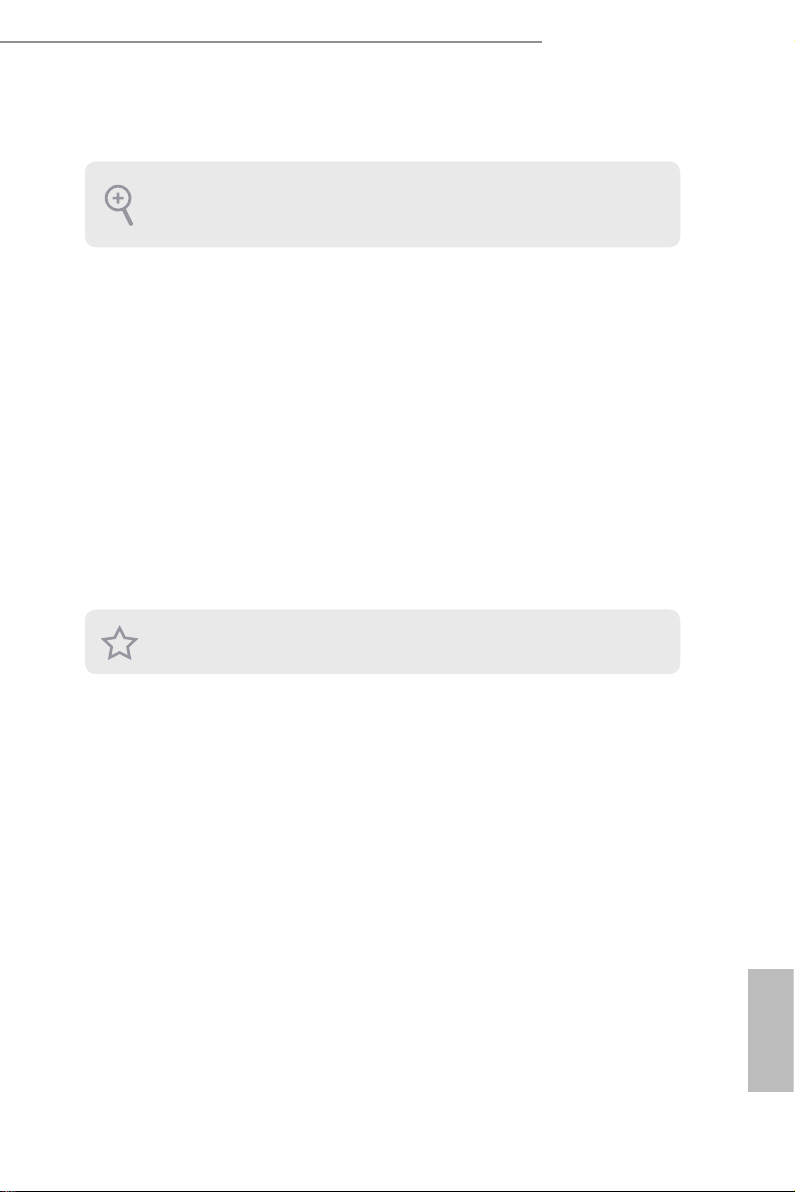
2.1 Front View
1 2
3
No. Description
1 Audio(Mic-in, Line-out)
2 2 x USB 3.2 Gen2 Ports (Type C, supports DP1.2a display output)
3 USB 3.2 Gen2 (Type A)
English
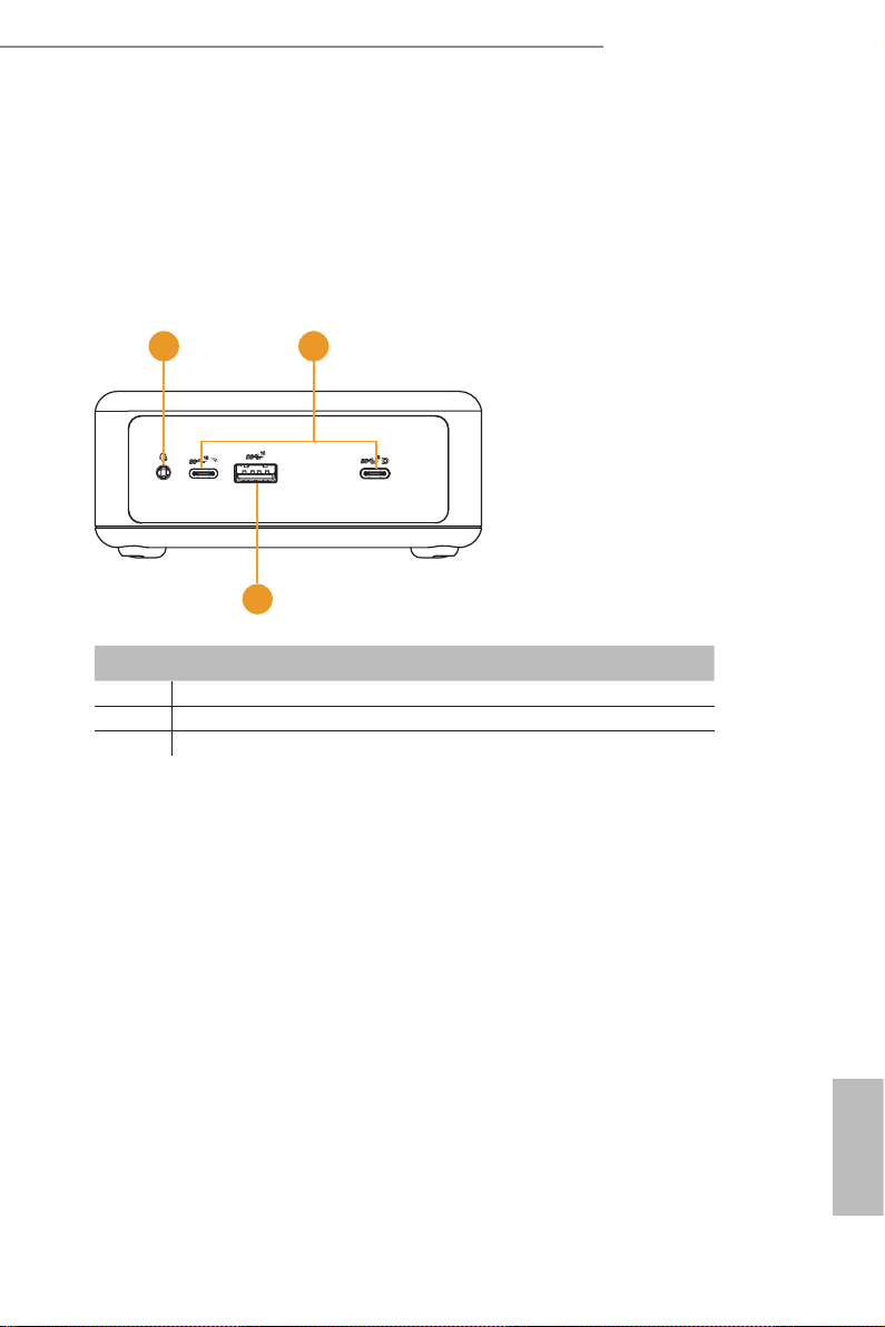
2.2 Rear View
1 2
4 5
No. Description
1 DC-IN
2 HDMI
3 RJ-45 (1G)*
4 2 x USB 2.0 Ports
5 DisplayPort
6 RJ-45 (2.5G)**
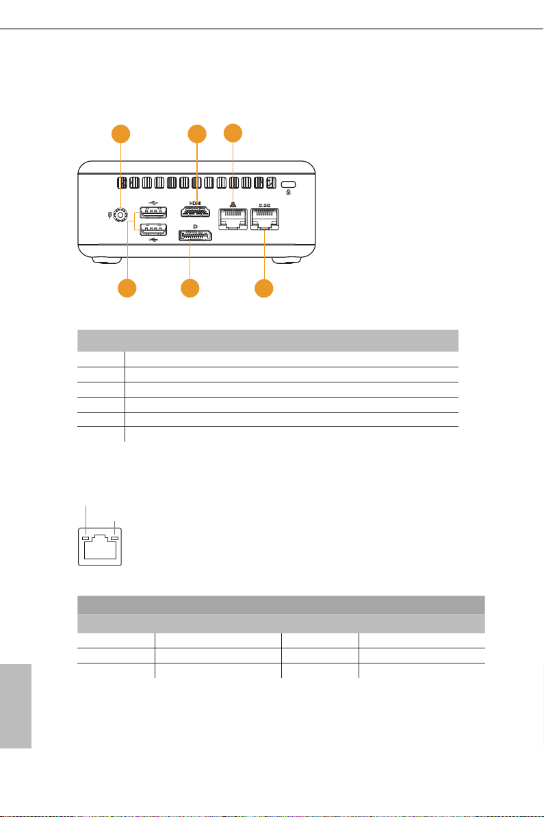
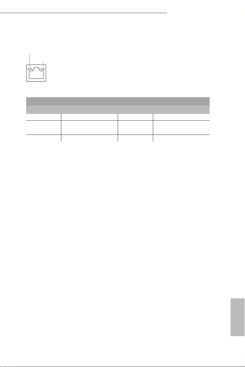
* ere are two LEDs on the LAN port. Please refer to the table below for the LAN port LED indications.
ACT/LINK LED
SPEED LED
3
6
LAN Por t
Activity / Link LED Speed LED
Status Description Status Description
O No Link O 10Mbps connection
Blinking Data Activity Orange 100Mbps connection
English
On Link Green 1Gbps connection
6 7
4X4 BOX-4000 Series
* ere are two LEDs on the LAN port. Please refer to the table below for the LAN port LED indications.
ACT/LINK LED
SPEED LED
LAN Por t
Activity / Link LED Speed LED
Status Description Status Description
O No Link O 10Mbps connection
Blinking Data Activity Orange 100Mbps/1Gbps
connection
On Link Green 2.5Gbps connection
English
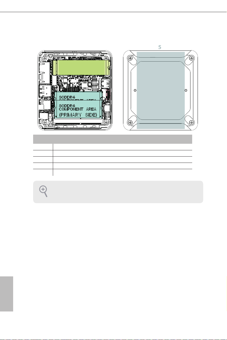
2.3 Inside View
5
4
3
2
1
No. Description
1 SO-DIMM Slot
2 SATA 3.0 Connector
3 Mini PCIe Slot
4 M.2 Slot
5 Hard disk drive tray (compatible with 2.5" SATA HDD/SSD)
SO-DIM M memory, hard drive and mSATA SSD are not inclu ded with this system.
English
8 9

Chapter 3 Hardware Installation
is chapter helps you install or remove important components.
3.1 How to Remove the Bottom Case
1. Remove the four screws on the bottom case.
2. en li up and remove the bottom panel..
1
2
4X4 BOX-4000 Series
English

3.2 How to Install the WiFi Module
1. Locate the WiFi Module slot on the motherboard.
2. Carefully insert the WiFi Module into the slot.
3. Tighten the screw to secure the WiFi Module to the motherboard.
English
10 11

3.3 How to Remove the M.2 SSD and the Bracket
1. Release the screw and carefully remove the M.2 SSD.
2. Release the screw and remove the bracket from the motherboard.
4X4 BOX-4000 Series
English

3.4 How to Install the M.2 SSD
1. Locate the M.2 slot on the motherboard
2. Carefully insert the M.2 SSD into the slot.
3. Tighten the screw to secure the M.2 SSD to the motherboard.
.
English
12 13

4X4 BOX-4000 Series
3.5 How to Install the 2.5-inch Hard Drive
1. Remove the four screws on the bottom case. en li up and remove the bottom panel.
2. Attach the HDD to the hard drive mounting bracket and secure it using the four
screws.
English

3. Connect the SATA Data and Power Cable to the HDD.
4. Connect the SATA Data and Power Cable to the HDD.
English
14 15

5. Connect the SATA Cable to the connector.
6. en reinstall the bottom panel.
4X4 BOX-4000 Series
English

3.6 How to Install the Memory Modules
(DDR4)
1. e 4X4 BOX-4000 Serie s requires DDR4 SO-DIMM.
2. For dual channel conguration, you always need to install identic al (the same brand,
speed , size and chip-type) DDR4 SO-DIMM pairs.
e SO-DIMM only ts in one cor rect orientation. It w ill cau se permanent damage to the
motherboard and the DIMM if you force the DIMM into the slot at incorrect orientation.
1. Carefully insert the SO-DIMM memory modules into the slot at a 30-degree angle.
2. Push down until the modules snap into place.
English
16 17

Chapter 4 Motherboard
4.1 Motherboard Layout
4X4 BOX-4000 Series
1 :
SIO_AT1
2 :
M.2 Key-M Socket (M2M_1)
3 :
M.2 Key-E Socket (M2E_1)
4 :
Front Panel Audio Header
5 : USB2.0 Connector (USB2H_1_2)
6 :
COM Port Header (RS232/422/485)
7 : SATA3 Port (SATA3_0)
8 :
Clear CMOS Header (CLRCMOS1)
9 :
System Panel Header (PANEL1)
Back Side :
Power Button (PWR_BTN3)
Fan Connector (FAN1)
Battery Connector (BAT1)
LPC Connector (LPC1)
English

4.2 Motherboard Specications
English
Form
Factor
Processor
System
Expansion
Slot
Memory
Graphics
Audio
Ethernet
Front I/O
Rear I/O
Dimensions NUC 4.09" x 4.02" (104 x 102mm)
4X4-4800U:
AMD Ryzen™ 7 4800U (Max Speed up to 4.2GHz)
CPU
Chipset SoC
BIOS AMI SPI 128 Mbit
M.2
Technology Dual Channel DDR4 3200 MHz
Capacity 64GB (32 GB per DIMM)
Socket 2 x 260-pin SO-DIMM
Controller AMD Radeon™ Graphics
HDMI
DisplayPort
Multi Display Max 4 display (Included 2 outputs from type C)
Interface Realtek ALC233, High Denition Audio.
Controller/
Speed
Connector 2 x RJ-45
USB
Audio 1 (headphone & microphone jack)
HDMI 1 x HDMI 2.0a
DisplayPort 1 x DP1.2a
Ethernet 2 x 1 Gigabit LAN
USB 2 x USB 2.0
DC Jack 1
4X4-4500U:
AMD Ryzen™ 5 4500U (Max Speed up to 4.0GHz)
4X4-4300U:
AMD Ryzen™ 3 4300U (Max Speed up to 3.7GHz)
1 x M.2 (Key E, 2230) with PCIe x1, USB 2.0 and
CNVio for Wireless
HDMI 2.0a
Max resolution up to 4096x2160@60Hz
DisplayPort 1.2a, DP++
Max resolution up to 4096x2160@60Hz
LAN1: 1 x Realtek RTL8125BG with
10/100/1000/2500 Mbps
LAN1: 1 x Realtek R8111FPV (Dash) with
10/100/1000 Mbps
2 x USB 3.2 Gen2 (Type A)
2 x USB 3.2 Gen2 (Type C) (Supports DP1.2a
display output)
18 19

Internal
Connector
Storage
Watchdog
Timer
Power
Requirements
Environment
4X4 BOX-4000 Series
USB 2 x USB2.0 (1 x 2.54 pitch header)
COM 1 x COM (RS-232/422/485)
TPM Innion SLB9670VQ2.0
eDP 1
1 x M.2 (KEY M, 2242/2260/2280) with
M.2
SATA 1 x SATA3.0 (6.0 Gb/s)
Output From Super I/O to drag RESETCON#
Interval 256 segments, 0,1,2…255sec
Input PWR 12V~19V DC-In Jack
Power On
Operating
Temp
Storage
Temp
Operating
Humidity
Storage
Humidity
PCIe x4 and SATA3 for SSD
*M.2 Key M 2280 (Supported by bracket)
AT/ATX Supported
AT: Directly PWR on as Power input ready
Environment ATX: Press Button to PWR on
after Power input ready
0ºC ~ 60ºC
-40ºC ~ 85°C
5% ~ 90%
5% ~ 90%
English

4.3 Jumpers Setup
The illustration shows how jumpers are
setup. When the jumper cap is placed on
pins, the jumper is “Short”. If no jumper cap
is placed on pins, the jumper is “Open”. The
illustration shows a 3-pin jumper whose
pin1 and pin2 are “Short” when jumper cap
is placed on these 2 pins.
Clear CMOS Jumper
(3-pin CLRMOS1)
(see p.8, No. 8)
Clear CMOSDefault
Note: CLRMOS1 allows you to clear the data in CMOS. To clear and reset the
system parameters to default setup, please turn o the computer and unplug
the power cord from the power supply. After waiting for 15 seconds, use a
jumper cap to short pin2 and pin3 on CLRMOS1 for 5 seconds. However,
please do not clear the CMOS right after you update the BIOS. If you need
to clear the CMOS when you just nish updating the BIOS, you must boot up
the system rst, and then shut it down before you do the clear-CMOS action.
Please be noted that the password, date, time, user default prole and MAC
address will be cleared only if the CMOS battery is removed.
ATX/AT Mode Jumper Open : ATX Mode
(2-pin SIO_AT1)
(see p.8, No. 1)
Short : AT Mode
English
20 21

4X4 BOX-4000 Series
1
4.4 Onboard Headers and Connectors
Onboard headers and connectors are NOT jumpers. Do NOT place
jumper caps over these headers and connectors. Placing jumper caps
over the headers and connectors will cause permanent damage of the
motherboard!
USB 2.0 Connector There is one USB 2.0
(9-pin USB2H_1_2)
(see p.8 No. 5)
System Panel Header This header accommodates
(9-pin PANEL1)
(see p.8 No. 9)
connector on this
motherboard.
several system front panel
functions.
HDLED+
HDLED-
GND
RESET#
DUMMY
NC
DUMMY
PLED+
PLED-
PWRBTN#
GND
Connect the power switch, reset switch and system status indicator on the
chassis to this header according to the pin assignments below. Note the
positive and negative pins before connecting the cables.
PWRBTN (Power Switch):
Connect to the power switch on the chassis front panel. You may congure
the way to turn o your system using the power switch.
RESET (Reset Switch):
Connect to the reset switch on the chassis front panel. Press the reset
switch to restart the computer if the computer freezes and fails to perform a
normal restart.
PLED (System Power LED):
Connect to the power status indicator on the chassis front panel. The LED
is on when the system is operating. The LED keeps blinking when the sys-
tem is in S1 sleep state. The LED is o when the system is in S3/S4 sleep
state or powered o (S5).
HDLED (Hard Drive Activity LED):
Connect to the hard drive activity LED on the chassis front panel. The LED
is on when the hard drive is reading or writing data.
The front panel design may dier by chassis. A front panel module mainly
consists of power switch, reset switch, power LED, hard drive activity LED,
speaker and etc. When connecting your chassis front panel module to this
header, make sure the wire assignments and the pin assign-ments are
matched correctly.
English

Front Panel Audio Header This is an interface for front
(9-pin HD_AUDIO1)
(see p.8 No. 4)
panel audio cable that allows
convenient connection and
control of audio devices.
Signal
PIN
Name
2 AGND 4 NC 6 LIN1_JD 8 LIN2_JD 10 NC
LIN1_L_
1
IN
1. High Denition Audio supports Jack Sensing, but the panel wire on
the chassis must support HDA to function correctly. Please follow the
instruction in our manual and chassis manual to install your system.
2. If you use AC’97 audio panel, please install it to the front panel audio
header as below:
A. Connect Mic_IN (MIC) to MIC2_L.
B. Connect Audio_R (RIN) to OUT2_R and Audio_L (LIN) to OUT2_L.
C. Connect Ground (GND) to Ground (GND).
D. MIC_RET and OUT_RET are for HD audio panel only. You don’t
need to connect them for AC’97 audio panel.
E. To activate the front mic.
Go to the “FrontMic” Tab in the Realtek Control panel. Adjust
“Recording Volume”.
PIN
3
Signal
Name
LIN1_R_
IN
PIN
5
Signal
Name
LIN2_R_
OUT
Signal
PIN
Name
7 AGND 9
PIN
Signal
Name
LIN2_L_
OUT
COM Port Header (RS232/422/485)
(9-pin COM1: see p.8, No. 6)
* This motherboard supports RS232/422/485 on COM1 port. Please refer to below table for the pin
denition. In addition, COM1 port (RS232/422/485) can be adjusted in BIOS setup utility > Advanced
Screen > Super IO Conguration. You may refer to page 23 for details.
RRXD1
DDTR#1
1
TTXD1
DDCD#1
DDSR#1
CCTS#1
RRTS#1
GND
RRI#1
COM1 Port Pin Denition
PIN RS232 RS422 RS485
1 DCD, Data Carrier Detect TX- RTX2 RXD, Receive Data TX+ RTX+
3 TXD, Transmit Data RX+ N/A
4 DTR, Data Terminal Ready RX- N/A
English
5 GND GND GND
6 DSR, Data Set Ready N/A N/A
7 RTS, Request To Send N/A N/A
8 CTS, Clear To Send N/A N/A
9 N/A N/A N/A
22 23

Back Side:
FAN_SPEED_CONTROL
FAN_SPEED
+12V
GND
Power Button Header
(PWR_BTN3)
Fan Connector
(FAN1)
1
4X4 BOX-4000 Series
English

4.5 Expansion Slots (M.2 Slots)
There are 2 M.2 slots on this motherboard.
M.2 for SSD:
1 x M.2 (KEY M, 2242/2260/2280) with PCIe x4 and SATA3 for SSD.
* M.2 Key M 2280 (Supported by bracket)
M.2 for Wi-Fi:
1 x M.2 (Key E, 2230) with PCIe x1, USB 2.0 and CNVio for
Wireless.
M.2 Key-M Socket (M2M_1) M.2 Key-E Socket (M2E_1)
PIN Signal Name PIN Signal Name
1 GND 2 +3.3V
3 GND 4 +3.3V
5 PERn3 6 USB_D+
7 PERp3 8 USB_D-
9 GND 10 SATA_LED
11 PETn3 12 +3.3V
13 PETp3 14 +3.3V
15 GND 16 +3.3V
17 PERn2 18 +3.3V
19 PERp2 20 NA
21 GND 22 NA
23
25
27 GND 28 NA
29 PERn1 30 NA
31 PERp1 32 NA
33 GND 34 NA
35 PETn1 36 NA
37 PETp1 38 DEVSLP
39 GND 40 SMB_CLK
41 PERn0/ SATA-B+ 42 SMB_DATA
43 PERp0/ SATA-B- 44 NA
45 GND 46 NA
47 PETn0/ SATA-A- 48 NA
49 PETP0/ SATA-A+ 50 PERST#
51 GND 52 CLKREQ#
53 PEFCLKn 54 WAKE#
55 PEFCLKp 56 NA
57 GND 58 NA
67 NA 68 NA
69 PEDET 70 +3.3V
71 GND 72 +3.3V
73 GND 74 +3.3V
75 GND
PETn2
PETp2
24
NA
26
NA
* Pin6 and Pin8 are dened as USB2.0
signal to support Key-M to Key-B exten-
sion card.
PIN Signal Name PIN Signal Name
1 GND 2 +3.3V
3 USB_D+ 4 +3.3V
5 USB_D- 6 NA
7 GND 8 NA
9 NA 10 NA
11 NA 12 NA
13 NA 14 NA
15 NA 16 NA
17 NA 18 GND
19 NA 20 NA
21 NA 22 NA
23 NA
33
35
37 PETn 36 NA
39 GND 38 NA
41 PERp 40 NA
43 PERn 42 NA
45 GND 44 NA
47 PEFCLKp 46 NA
49 PEFCLKn 48 NA
51 GND 50 SUSCLK
53 CLKREQ# 52 PERST0#
55 WAKE# 54 W_DISABLE1#
57 GND 56 W_DISABLE2#
59 NA 58 SMB_DATA
61 NA 60 SMB_CLK
63 GND 62 NA
65 NA 64 NA
67 NA 66 NA
69 GND 68 NA
71 NA 70 NA
73 NA 72 +3.3V
75 GND 74 +3.3V
32
GND
PETp
NA
34
NA
English
24 25

4X4 BOX-4000 Series
Chapter 6 UEFI Setup Utility
6.1 Introduction
This section explains how to use the UEFI SETUP UTILITY to congure your
system. The UEFI chip on the motherboard stores the UEFI SETUP UTILITY. You
may run the UEFI SETUP UTILITY when you start up the computer. Please press
<F2> or <Del> during the Power-On-Self-Test (POST) to enter the UEFI SETUP
UTILITY, otherwise, POST will continue with its test routines.
If you wish to enter the UEFI SETUP UTILITY after POST, restart the system by
pressing <Ctl> + <Alt> + <Delete>, or by pressing the reset button on the system
chassis. You may also restart by turning the system o and then back on.
Because the UEFI software is constantly being updated, the
following UEFI setup screens and descriptions are for reference
purpose only, and they may not exactly match what you see on
your screen.
6.1.1 UEFI Menu Bar
The top of the screen has a menu bar with the following selections:
Main
Advanced
H/W Monitor
Security
Boot
Exit
Use < > key or < > key to choose among the selections on the menu
bar, and then press <Enter> to get into the sub screen. You can also use the
mouse to click your required item.
To set up the system time/date information
To set up the advanced UEFI features
To display current hardware status
To set up the security features
To set up the default system device to locate and load the
Operating System
To exit the current screen or the UEFI SETUP UTILITY
English

6.1.2 Navigation Keys
Please check the following table for the function description of each navigation
key.
Navigation Key(s) Function Description
/
Moves cursor left or right to select Screens
/
Moves cursor up or down to select items
+ / -
<Enter>
<F1>
To display the General Help Screen
<F7>
Discard changes
<F9>
<F10>
<F12>
Print screen
<ESC>
To jump to the Exit Screen or exit the current screen
To change option for the selected items
To bring up the selected screen
To load optimal default values for all the settings
To save changes and exit the UEFI SETUP UTILITY
6.2 Main Screen
When you enter the UEFI SETUP UTILITY, the Main screen will appear and display
the system overview.
English
26 27

4X4 BOX-4000 Series
6.3 Advanced Screen
In this section, you may set the congurations for the following items: CPU Congu-
ration, Chipset Conguration, Storage Conguration, Super IO Conguration, ACPI
Conguration, USB Conguration, Trusted Computing, MCTP Conguration and Se-
rial Port Console Redirection.
Setting wrong values in this section may cause
the system to malfunction.
DASH Support
Enable or disable Realtek Lan DASH Function.
Instant Flash
Instant Flash is a UEFI ash utility embedded in Flash ROM. This conve-
nient UEFI update tool allows you to update system UEFI without entering
operating systems rst like MS-DOS or Windows®. Just launch this tool
and save the new UEFI le to your USB ash drive, oppy disk or hard
drive, then you can update your UEFI only in a few clicks without prepar-
ing an additional oppy diskette or other complicated ash utility. Please
be noted that the USB ash drive or hard drive must use FAT32/16/12 le
system. If you execute Instant Flash utility, the utility will show the UEFI
les and their respective information. Select the proper UEFI le to update
your UEFI, and reboot your system after UEFI update process completes.
English

6.3.1 CPU Conguration
Cool ‘n‘ Quiet
Use this item to enable or disable AMD’s Cool ‘n’ QuietTM technology.
The default value is [Enabled]. Conguration options: [Enabled] and [Dis-
abled]. If you install Windows® OS and want to enable this function, please
set this item to [Enabled]. Please note that enabling this function may re-
duce CPU voltage and memory frequency, and lead to system stability or
compatibility issue with some memory modules or power supplies. Please
set this item to [Disable] if above issue occurs.
Core Performance Boost
Core Performance Boost controls whether the processor transitions to a
higher frequency than the processor's rated speed if the processor has
available power and is within temperature specications. The default value
is [Enabled].
SVM Mode
When this is set to [Enabled], a VMM (Virtual Machine Architecture) can
utilize the additional hardware capabilities provided by AMD-V. The default
value is [Enabled]. Conguration options: [Enabled] and [Disabled].
English
28 29

4X4 BOX-4000 Series
6.3.2 Chipset Conguration
Share Memory
Congure the size of memory that is allocated to the integrated graphics
processor when the system boots up.
Onboard HD Audio
Select [Enabled] or [Disabled] for the onboard HD Audio feature.
Verb Table Select
The default value is [Combo Jack].
Onboard LAN 1
This allows you to enable or disable the Onboard LAN 1.
Onboard LAN 2
This allows you to enable or disable the Onboard LAN 2.
Restore on AC/Power Loss
Select the power state after a power failure. If [Power O] is selected, the
power will remain o when the power recovers. If [Power On] is selected,
the system will start to boot up when the power recovers.
Deep S5
[Auto] will disable the deep S5 conguration if RTC/LAN/USB
device power on settings are enabled. The default value is
[Disabled].
English

6.3.3 Storage Conguration
SATA Controller(s)
Use this item to enable or disable the SATA Controller feature.
SATA Mode Selection
Use this to select SATA mode. The default value is [AHCI Mode].
AHCI (Advanced Host Controller Interface) supports NCQ
and other new features that will improve SATA disk perfor-
mance but IDE mode does not have these advantages.
Aggressive Link Power Management
Use this item to congure SATA Aggressive Link Power Management.
Hard Disk S.M.A.R.T.
Use this item to enable or disable the S.M.A.R.T. (Self-Monitoring, Analy-
sis, and Reporting Technology) feature. Conguration options: [Disabled]
and [Enabled].
English
30 31

6.3.4 Super IO Conguration
COM1 Conguration
Use this to set parameters of COM1.
Type Select
Use this to select COM1 port type: [RS232], [RS422] or [RS485].
WDT Timeout Reset
Use this to set the Watch Dog Timer.
4X4 BOX-4000 Series
English

6.3.5 ACPI Conguration
Suspend to RAM
Use this item to select whether to auto-detect or disable the Suspend-to-
RAM feature. Select [Auto] will enable this feature if the OS supports it.
Onboard LAN Power On
Use this item to enable or disable onboard LAN to turn on the system from
the power-soft-o mode.
RTC Alarm Power On
Use this item to enable or disable RTC (Real Time Clock) to power on the
system.
English
32 33

6.3.6 USB Conguration
Legacy USB Support
Use this option to select legacy support for USB devices. There are two
conguration options: [Enabled] and [UEFI Setup Only]. The default value
is [Enabled]. Please refer to below descriptions for the details of these two
options:
[Enabled] - Enables support for legacy USB.
[UEFI Setup Only] - USB devices are allowed to use only under UEFI
setup and Windows / Linux OS.
USB Power Control
Use this to control USB power. The default value is [Default Setting].
4X4 BOX-4000 Series
English

6.3.7 Trusted Computing
Security Device Support
Enable or disable BIOS support for security device.
English
34 35

4X4 BOX-4000 Series
6.4 Hardware Health Event Monitoring Screen
In this section, it allows you to monitor the status of the hardware on your system,
including the parameters of the CPU temperature, motherboard temperature, CPU
fan speed, chassis fan speed, and the critical voltage.
CPU_FAN1 Setting
This allows you to set CPU_FAN1’s speed. Configuration options: [Full
On], [Manual] and [Automatic Mode]. The default value is [Automatic
Mode].
English

6.5 Security Screen
In this section, you may set, change or clear the supervisor/user password for the
system.
Supervisor Password
Set or change the password for the administrator account. Only the ad-
ministrator has authority to change the settings in the UEFI Setup Utility.
Leave it blank and press enter to remove the password.
User Password
Set or change the password for the user account. Users are unable to
change the settings in the UEFI Setup Utility. Leave it blank and press en-
ter to remove the password.
Secure Boot
Enable to support Windows 8.1 / 8 Secure Boot.
English
36 37

4X4 BOX-4000 Series
6.6 Boot Screen
In this section, it will display the available devices on your system for you to cong-
ure the boot settings and the boot priority.
Boot From Onboard LAN
Use this item to enable or disable the Boot From Onboard LAN feature.
Setup Prompt Timeout
This shows the number of seconds to wait for setup activation key.
65535(0XFFFF) means indenite waiting.
Bootup Num-Lock
If this item is set to [On], it will automatically activate the Numeric Lock
function after boot-up.
Full Screen Logo
Use this item to enable or disable OEM Logo. The default value is [Enabled].
English

CSM (Compatibility Support Module)
CSM
Enable to launch the Compatibility Support Module. Please do not disable
unless you’re running a WHCK test. If you are using Windows 8.1 64-bit
and all of your devices support UEFI, you may also disable CSM for faster
boot speed.
Launch PXE OpROM Policy
Select UEFI only to run those that support UEFI option ROM only. Select
Legacy only to run those that support legacy option ROM only. Select Do
not launch to not execute both legacy and UEFI option ROM.
Launch Storage OpROM Policy
Select UEFI only to run those that support UEFI option ROM only. Select
Legacy only to run those that support legacy option ROM only. Select Do
not launch to not execute both legacy and UEFI option ROM.
Launch Video OpROM Policy
Select UEFI only to run those that support UEFI option ROM only. Select
Legacy only to run those that support legacy option ROM only. Select Do
not launch to not execute both legacy and UEFI option ROM.
English
38 39

6.7 Exit Screen
Save Changes and Exit
When you select this option, it will pop-out the following message, “Save
conguration changes and exit setup?” Select [OK] to save the changes
and exit the UEFI SETUP UTILITY.
Discard Changes and Exit
When you select this option, it will pop-out the following message, “Discard
changes and exit setup?” Select [OK] to exit the UEFI SETUP UTILITY
without saving any changes.
Discard Changes
When you select this option, it will pop-out the following message, “Discard
changes?” Select [OK] to discard all changes.
Load UEFI Defaults
Load UEFI default values for all the setup questions. F9 key can be used
for this operation.
Launch EFI Shell from lesystem device
Attempts to Launch EFI Shell application (Shell64.efi) from one of the
available lesystem devices.
4X4 BOX-4000 Series
English

Chapter 8 Software Support
8.1 Install Operating System
This motherboard supports various Microsoft® Windows® operating systems:
10 64-bit / 8.1 64-bit / 7 32-bit / 7 64-bit. Because motherboard settings and hard-
ware options vary, use the setup procedures in this chapter for general reference
only. Refer your OS documentation for more information.
8.2 Support CD Information
The Support CD that came with the motherboard contains necessary drivers and
useful utilities that enhance the motherboard’s features.
8.2.1 Running The Support CD
To begin using the support CD, insert the CD into your CD-ROM drive. The
CD automatically displays the Main Menu if “AUTORUN” is enabled in your
computer. If the Main Menu did not appear automatically, locate and double
click on the le “ASRSETUP.EXE” from the BIN folder in the Support CD to
display the menus.
8.2.2 Drivers Menu
The Drivers Menu shows the available device’s drivers if the system detects
installed devices. Please install the necessary drivers to activate the devices.
8.2.3 Utilities Menu
The Utilities Menu shows the application software that the motherboard sup-
ports. Click on a specic item then follow the installation wizard to install it.
8.2.4 Contact Information
If you need to contact ASRock or want to know more about ASRock, you’re
welcome to visit ASRock’s website at http://www.asrock.com; or you may con-
tact your dealer for further information.
English
40 PB
 Loading...