

Page 1
PROXlIVlAf
Desktop Projector 5950
English
English
Español
• PRESEWTOTIO
• WORKING SESSIONS
-TRAINING
Page 2

'"«FORMATION TO THE USER
TE: This equipment has been tested and found to comply with the limits for a Class A digital device, pursue-
to Part 15 of the FCC Rules, These limits are designed to provide reasonable protection against hanf.
interference when the equipment is operated in a commercial environment This equipment generate
uses, and can radiate radio frequency energy and, if not installed and used in accordance with the user
guide, may cause harmful interference to radio communications. Operation of this equipment in
residential area is iikeiy to cause harmful tnierference in which case the user will be required to correc
the interference at his own expense.
TO THE OWNER
c
As the owner of a Desktop Projector 5950, you are probably eager to try out your new projector. Before you dc
m
we suggest that you spend a little time reading this guide to famiOarize yourself with the operating procedures
so that you will receive maximum satisfaction from the many features included in your new projector.
This user’s guide will acquaint you with your projector’s features. Reading it will help us too. Through the years
we have found that many service requests were not caused by problems with our projectors. They were cause«
by problems that could have been prevented, if the owner had followed the instructions in the guide.
You can often correct operating problems yourself. If your projector fails to work properly, se«
’TROUBLESHOOTING" section on pages 49 ~ 50 and try the solutions marked for each problem.
C
WARNING:
REDUCE THE RISK OF FIRE OR ELECTRIC SHOCK, DO NOT EXPOSE THIS APPLIANCE TO RAIN 0«
kOlSTURE. 1
This Projector has a grounding-type AC line plug. This is a safety feature to be sure that the plug will fit
into the power outlet. Do not try to defeat this safety feature.
intense light source. Do not stare directly into the projection lens as possible eye damage could result
Be especially careful that children do not stare directly into the beam.
If the Projector will not be used for an extended time, unplug the new Projector from the power outlet
READ AND KEEP THIS USER’S GUIDE FOR LATER USE.
CAUTION
RISK OF ELECTRIC SHOCK
A
CAUTION: TO REDUCE THE RISK OF ELECTRIC SHOCKy:DOiNOT REMOVE COVER (ORJ
BACK). NO USER-SERVICEABLE PARTS INSIDE EXCEPT^LAMP REPLACEMENT, REFER
SERVICING TO QUALIFIED SERVICE PERSONNEL. Lh
DO NOT OPEN
D
SAFETY PRECAUTIONS
ÆBBSAÊBÊA
THIS SYtlBOL INDICATES THAT DANGER
OUS VOLTAGE CONSTITUTING A RISK OF
ELECTRIC SHOCK IS PRESENT WITHIN
THIS UNIT.
THIS-SYMBOL-INDICATES THAT THERE ARE{
: (MPORTANT-ORERATiNG ANDWlAiNTENAHCEi
INSTRUCTIONS IN THE USER’S GUIDE wmf'
THIS UNIT. - %
Page 3
IMPORTANT SAFETY INSTRUCTIONS
c
■ 'I the safety and operating instructions should be read
the product is operated.
Read all of the instructions given here and retain them for
later use. Unplug this projector from AC power supply
before cleaning. Do not use liquid or aerosol cleaners. Use
a damp doth for cleaning.
Do not use attachments not recommended by the
manufacturer as they may cause hazards.
Do not place this projector on an unstable cart, stand, or
table. The projector may fall, causing serious injury to a
child or adult, and serious damage to the projector. Use
only with a cart or stand recommended by the
manufacturer, or sold with the projector. Wall or shelf
mounting should follow the manufacturer’s irrstructions,
and should use a mounting kit approved by the
manufacturer.
Do not expose this unit to rain or use near water... for
example, in a wet basement, near a swimming pool, etc...
Siots and openings in the back and bottom of the cabmet
are provided for ventilation, to insure reliable operation of
the equipment and to protect it from overheating.
\openings should never be covered with cloth or other
■ , f 'and the bottom opening should not be blocked by
,the projector on a bed. sofa. rug. or other similar
surface. This projector should never be placed near or
ever a radiator or heat register.
This projector should not be placed in a built-in installation
such as a bookcase unless proper ventilation is provided.
This projector should be operated only from the type of
power source indicated on the marking label. If you are no*
sure of the type of power supplied, consult your authorized
dealer or local power company.
Do not overload wall outlets and extension cords as this
can result in fire or electric shock. Do not allow anything to
rest on the
the cord may be damaged by persons walking on it.
Never push objects of any kind into this projector through
cabinet slots as they may touch dangerous voltage points
or short out parts that could result in a fire or electric
snock. Never spill liquid of any kind on the projector.
Do not attempt to service this proiector yourself as opening
cr removing covers may expose you to dangerous voltage
or other hazards. Refer ail servicing to' qualified ser\'ice
p " ortnef.
D. projector from wall outlet and refer servicing to
qualified service personnel under the following conditions:
pov^er cord. Do not locate this projector where
a. When the power cord or plug is damaged or frayed.
b. If liquid has been spilled into the projector,
c. If the projector has been exposed to rain or water.
d. if the projector does not operate normally by following
the operating instructions. Adjust only those controls
that are covered by the operating instruetjorrs as
improper adjustment of other controls may result in
damage and will often require extensive work by a
qualified technician to restore the projector to norma!
operation.
e. If the projector has been dropped or the cabinet has
been damaged. _
f. When Itie projector exhibits a distinct change inJ
performance-this indicates a need for service.
When replacement parts are required, be sure the service
technician has used replacement parts speciied by the
manufacturer that have the same characteristics as the
original part Unauthorized substitutions may result in fire,
electric shock, or injury to persons.
Upon completion of any service or repairs to ftiis projector,
ask the service technician to perform routine safety checks
to determine that the projector Is in safe operating
condition.
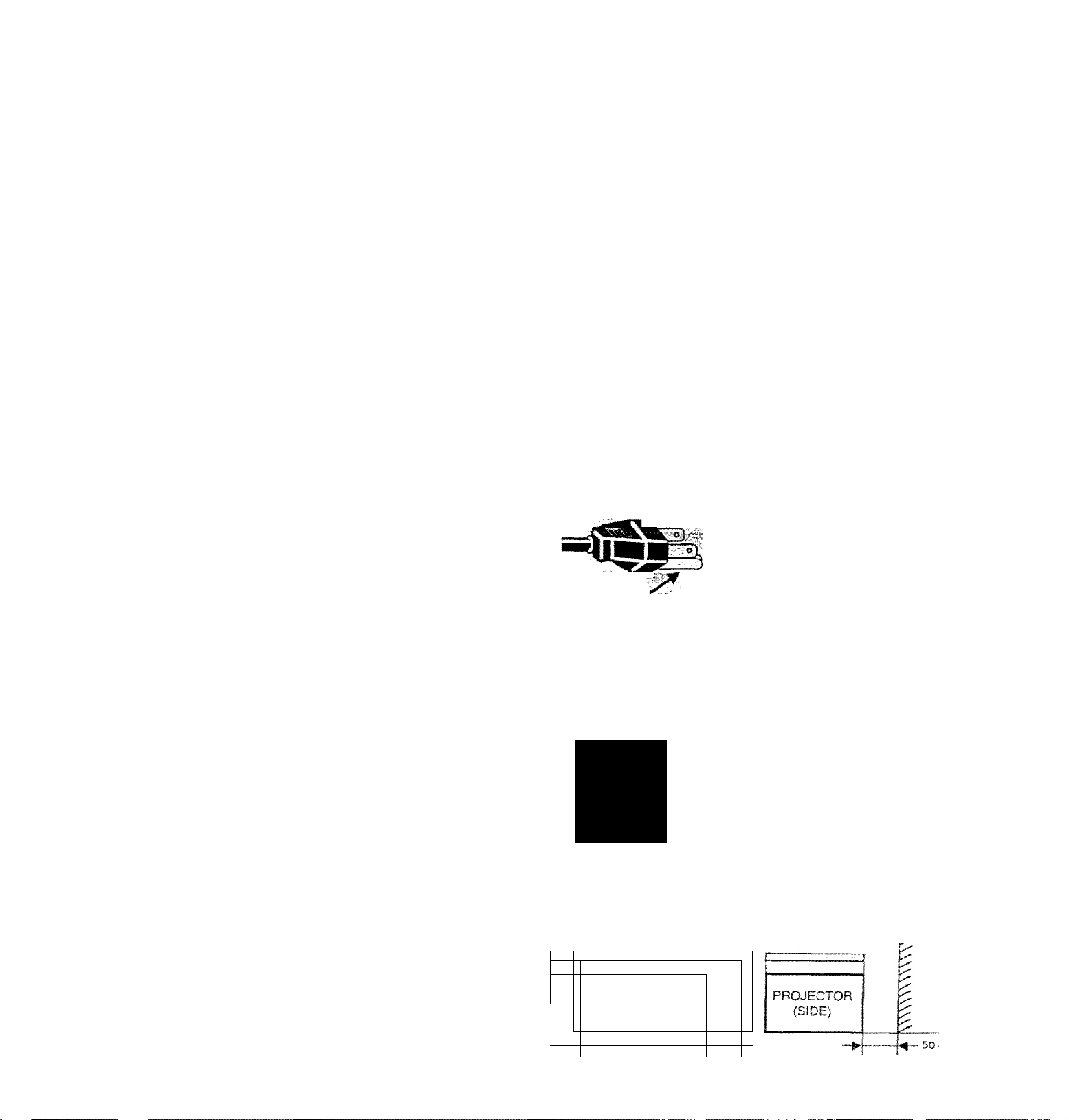
This projector is equipped with a
grounding type AC line plug.
Should you be unable to insert
the plug into the outlet, contact
your electrician. Do not defeat
GROUND
Follow all
projectors.
For added protection to the projector during a lightning
storm, or when it is left unattended and unused for tong
periods of time, unplug it from the wall outlet. This will
prevent damage due to lightning and powerline surges.
mw.
If the projector is to be built into a compartment or similarly
enclosed, the minimum distances must be maintained.
Do not cover the ventilation slot on the projector.
Heat bulld-up cars reduce the service life of your projector,
and can also be dangerous. , ^
1 r
-
20 cm
5
warnings
i
PROJECTOR
(FRONT)
the safety purpose of this
grounding type plug,
and instructions marked on the
An appliance and cart combination
should be moved with care. Quick
stops, excessive force, and uneven
surfaces may cause the appliance
and cart combination to overturn.
WAI
.So cm
Page 4

TABLE OF CONTENTS
PAGE
INTRODUCTION
COMPATlBiLITY
IMAGE RESOLUTION
PORTABILITY
UNPACKING THE PROJECTOR
TRADEMARKS
POWER REQUIREMENT
1 DESCRIPTION
SETTING-UP THE PROJECTOR
POSITIONING
ROOM LIGHT
VENTILATION
ADJUSTABLE FEET
MOVING THE PROJECTOR
CONNECTING THE PROJECTOR
CONNECTING THE COMPUTER
Connecting an IBM-compatible desktop computer
Connecting a Macintosh desktop computer
Connecting an IBM-compatible laptop computer
Connecting a Macintosh PowerBook computer
CONNECTING THE VIDEO EQUIPMENT
CONNECTING AN EXTERNAL SPEAKER
OPERATION OF CONTROLS
TOP OF THE PROJECTOR
REAR OF THE PROJECTOR
OPERATION OF REMOTE CONTROL
REMOTE CONTROL BATTERY INSTALLATION
USING THE REMOTE CONTROL UNIT
CONTROL THE PROJECTOR
DIRECT OPERATION
MENU OPERATION 25-26 . AIR FILTER CARE AND CLEANING
USING THE PROJECTOR 27-46
TO TURN ON THE PROJECTOR
TO TURN OFF THE PROJECTOR
DIRECT OPERATION
MODE SELECT
SOUND VOLUME ADJUSTMENT 28
5
■ 5
5
5
5 NORMAL PICTURE FUNCTION
5
6
7
8-9 AUTO IMAGE FUNCTION
8
8
8
9
9
10-17
10-14 PICTURE SCREEN ADJUSTMENT 33
11
12 COMPATIBLE COMPUTER SPECIFICATION 35
13
14
15-16
17 PC ADJUSTMENT
18-20
18-19
20 BLUE BACK 44-^
21-23
23
23 REAR
24-26
24
27
27
27 TROUBLESHOOTING
27 TECHNICAL SPECIFICATIONS
SOUND MUTE FUNCTION
ZOOM ADJUSTMENT
FOCUS ADJUSTMENT
DIGITAL ZOOM ADJUSTMENT
BLANK FUNCTION
P-TIMER FUNCTION 28
FREEZE PICTURE FUNCTION
MENU OPERATION
MODE SELECT
SOUND ADJUSTMENT 30
LANGUAGE ADJUSTMENT 30
COLOR SYSTEM SELECT
PICTURE IMAGE ADJUSTMENT
COMPUTER SYSTEM SELECT
AUTO IMAGE FUNCTION
PICTURE IMAGE ADJUSTMENT
PICTURE POSITION ADJUSTMENT 38'
PICTURE SCREEN ADJUSTMENT 43
OTHER FUNCTION SETTING
DISPLAY
CEILING
SPLIT WIPE
LAMP AGE 46
TEMPERATURE WARNING INDICATOR
LAMP REPLACEMENT
CLEANING THE LENS
,
PA
28
28
28
28
28
28
28
28
29-
29
31
32
34
3|-
%
39-^
44-^
44-i
44.,
44-^
44-i
47
47
48
49
49-5
51
Page 5

INTRODUCTION
c
The Desktop Proiectof 5950 is a muftmedta projector designed for portebtllly. duraWify, and ©ase of use The proJecto
res tjuífí-ín mufftmedta features, a palette of 16.77 milion colofs, and active matrix iquid crystal dlsoiav ILCD
Iwiinotogy. ^ ^ '
COMPATIBIOW'
The projector is compaflbte with many different ^pes of personal computers and video devices, incfoding;
• IBM-compaiibie computers, indodìng iaptops. up to 1024 x 760 resolution
•Apple Macifitosh and PowerSook computers tip to 1024 x 788 reso Won,
• Various VCRs, video disc players, video cameras. DVD players, satellite TV tunera or ofhisr AV ^
the worldwide video standards, including NTSC. NTSC4.43.PAL, SECAM ^d PAL-M ®<íUípment using any oi
IMAGE eeSOLUTIGN,
The resotuton: of the propcfor’s pr<|ect6d image is 800 x 6». The protector displays computer imaoes iust as thev
appear on your computers^monitor. Screen reploflops between 800 x 600 and 1024 x 768 Le compissi^L I»
600. The profector cannot display screen resolirtions above 1024 x ?ia ff wur eomauter’s screen Ithan 1024 X 768. reset ft to a lower resolufon before you connect fte computer s screen resoWon is higher
PORTABILITY
The pri^ector is e)dremeiy compact in size and weight. Having a sophisticated shape like an attaché case with a
relractaPie carrying handfe, the projector will help you make powerful presentations wherever you go
UNPACKING THE PROJECTOR
The profector comes wiih the parts listed below. Check to make sum ail are focluded If anv
auí.hónzed dealer or service station. ' ^ pans are missing, contact an
'' ‘'9r's Guide.
_ Powe,'" Cords ÍUL and European types).
• Hlmote Control Transmitter Unit and battenes.
• Lens Cover.
• Protective Dust Cover.
• VGA Cable.
• VGA/‘f4AC Adapter.
• Mouse Cable for PS/2 port.
• Mouse Cable lor serial port,
• Mouse Cable for A08 port.
• S-video cable (Mins DlN-4 type),
• AV cable ,'RCA t>'pe -x 3).
• PC audio cable (Stereo mini jack).
TRADEMARKS
• SSind f ”2 are trademarks or registered trademarks of Apple Comouter Inc
Desktop Projector is a trademark of Próxima Corporation
• Gtrier trademarks are the property of their respective owners.
Page 6
c
POWER REQUIREMENTS
_
••
Yoyr profector uses nomlnai input voitages o1 100-120 VAC or
200'240 VAC. The projector automaticaliy selects the correct
input voltage, it is designed to work with single-phase power
systems having a grounded neutral conducior. To reduce the rislc
of electilcai shock, do not plug into any other type of power
system.
Consult your authorized dealer or service station if you are not
sure of the type of power supply being in use.
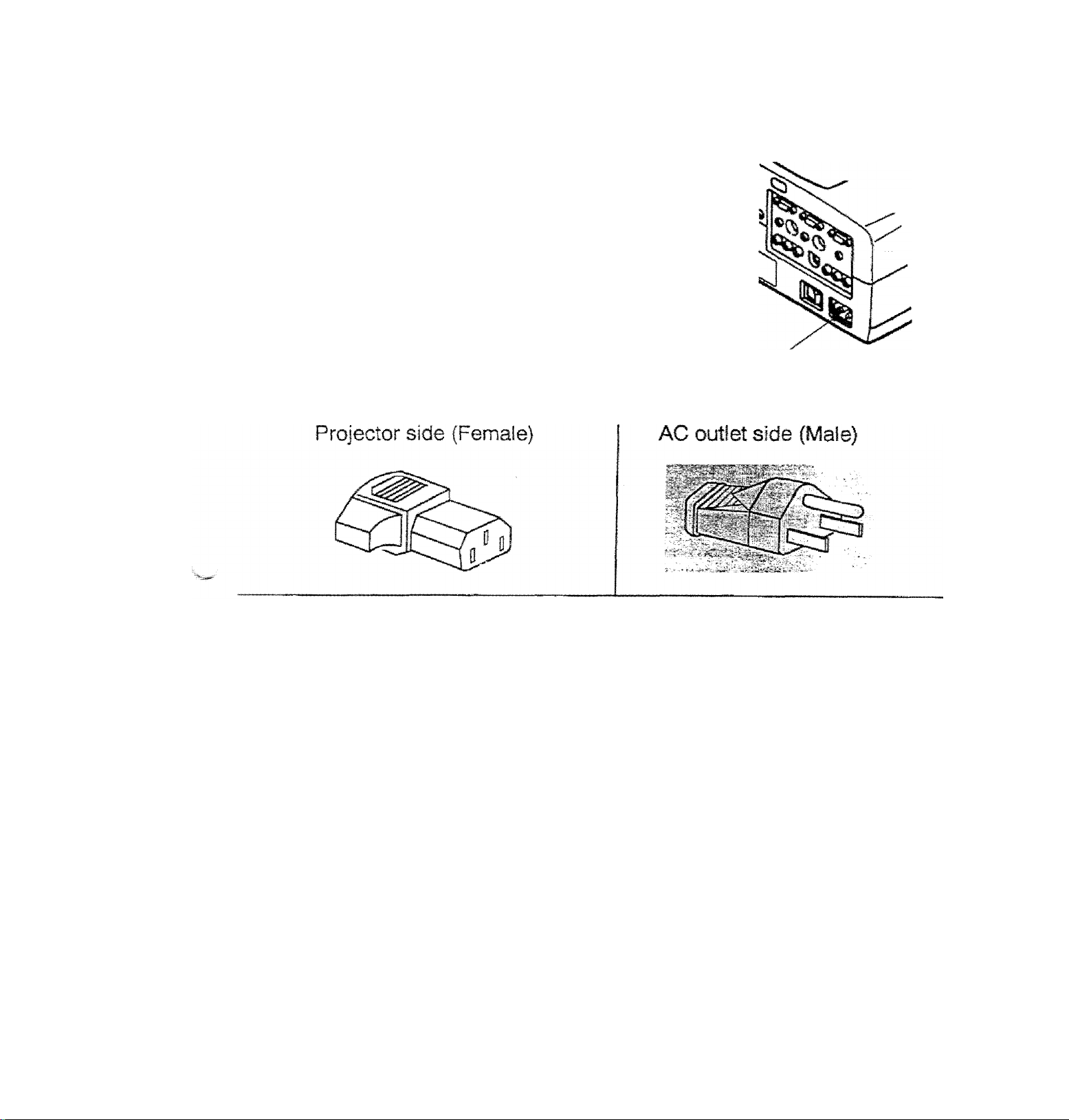
Connect the AC power supply cord (provi
i
the projector.
The socket-outlet must be near this eqt
and must be easily accessible.
Page 7
c
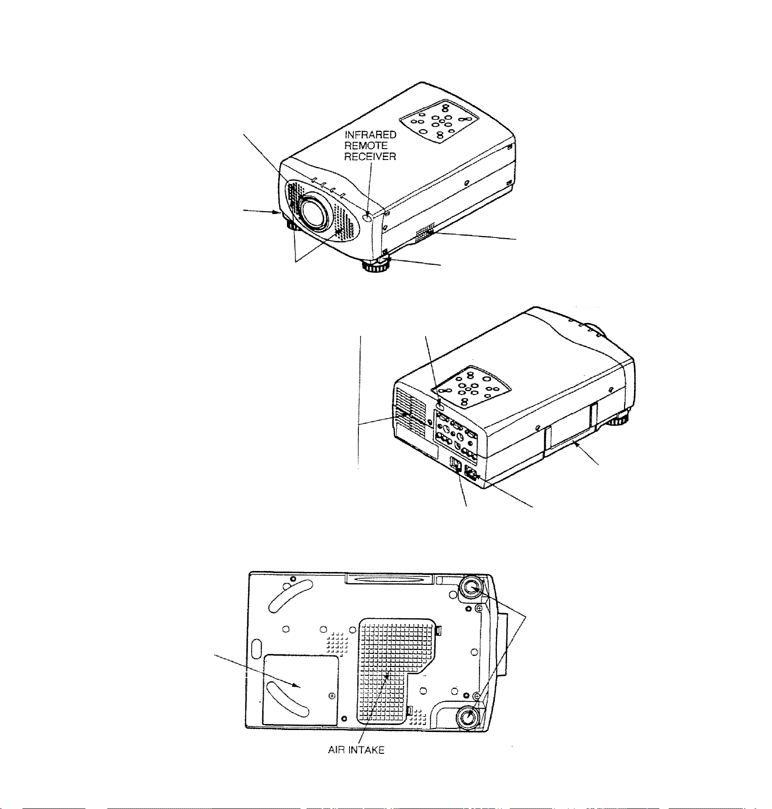
DESCRIPTION
9RONTj
projection lens
FEET LOCK
BUTTON
REMOVABLE
lens cover
-
-----
SPEAKERS
REAR
i EXHAUST VENT
A
1 CAUTION HOT AIR !
J "'ir blown from the exhaust vent is hoi.
jserve the following when handling your
Xpfojector or choosing a location to install it.
• Keep heat-sensitive objects away from the
‘ exhaust port.
^ handling.
I • Do not touch the cabinet near to the exhaust
I vent area, and especially screws and metallic
j parts. These parts will become hot while the
i projector is used.
: • If you set the projector on top of a metallic
surface, the surface will become hot because
; of the hot air exhaust. Be careful when
INFRARED
REMOTE
RECEIVER
MAIN ON/OFF
SWITCH
AIR INTAKE
VENT
FEET LOCK
BUTTON
CARRYING
HANDLE
POWER CORD
CONNECTOR
BOTTOM
LAMP cover
ADJUSTABLE
FEET
VENT
Page 8
c
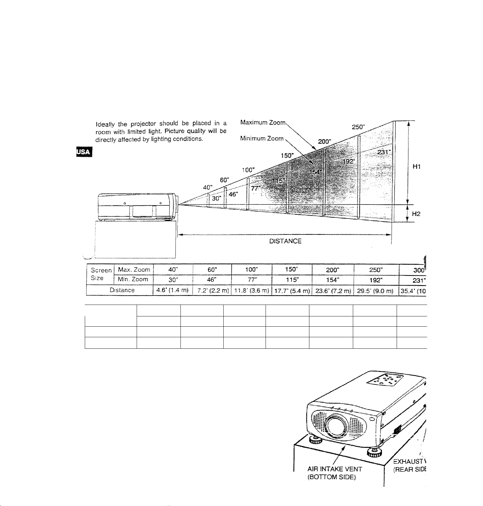
POSITIONING:
SETTING-UP THE PROJECTOR
This projector is basically designed to project on a flat projection surface.
This projector can be focused from 4.6’ (1.4 m) - 35.4’ (10.8 m).
Use the illustration below as an example when positioning the projector to the screen.
ROOM LIGHT
300”
Screen Size
(W X H) inch
Height (Hi)
Height (H2)
30”
24 X 18
17.1 inch
0.9 inch
60"
48 >■ 36
34.2 inch 57 inch
1.8 inch 3 inch j
100"
80 >• 60
120x90
85.5 inch
4.5 inch 6 inch
VENTILATION
This projector is equipped with a cooling fan to protect it from
overheating. Pay attention to the following to ensure the ventilation
and avoid a possible risk of fire and malfunction.
• Do not cover the vents with papers or other materials.
• Keep the rear grill at least 3.3’ (1m) away from any
A
object.
» Make sore that uiere are nc obiects under the proiscîor.
An object under the projector may prevent the projec&r
from taking the cooling air through the bottom vent
150”
200"
160 X 120
114 inch
250"
200 X 150
142.5 inch
7.5 inch
300”
240 X 1
171 inc
9 inch
Page 9
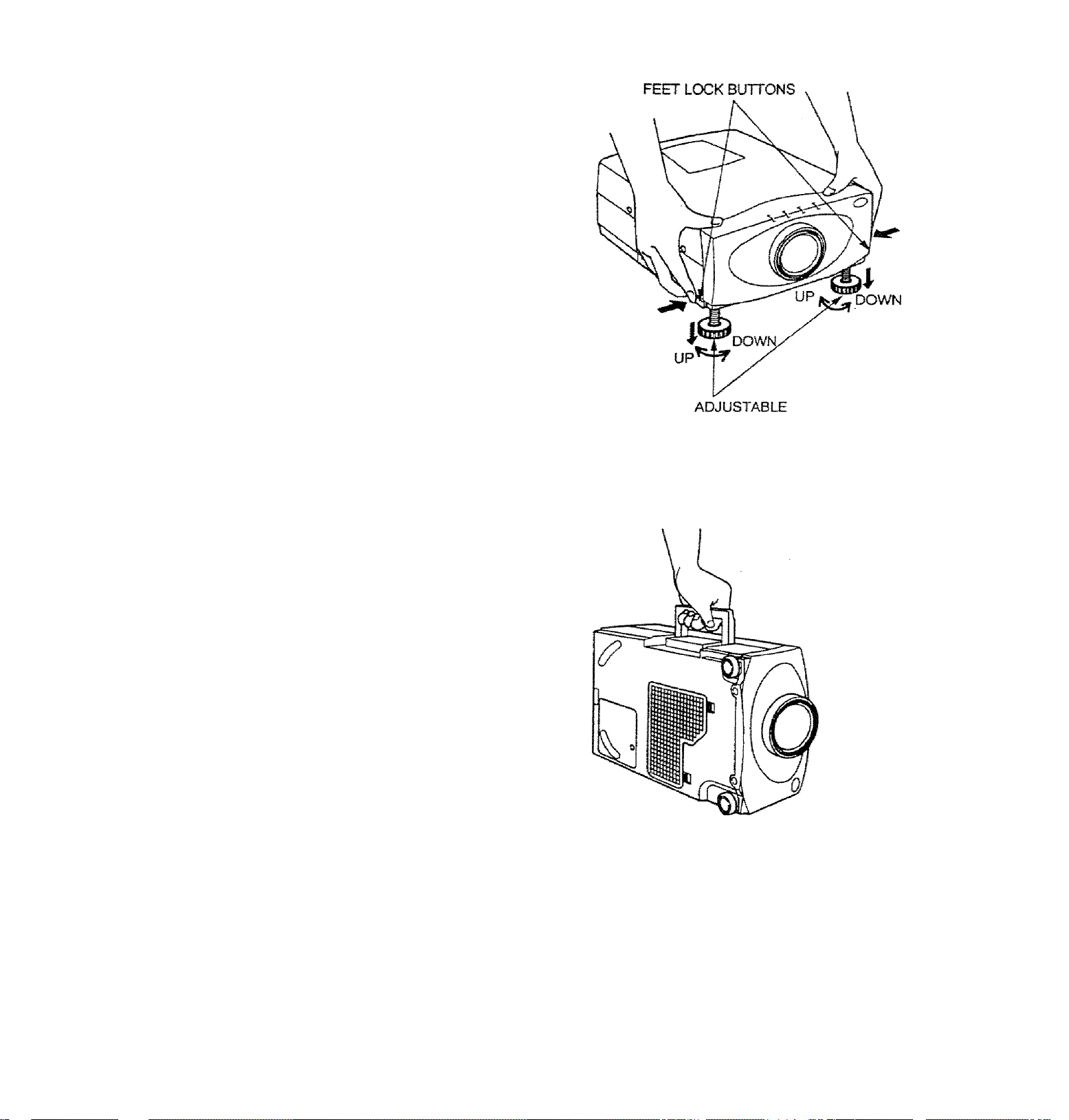
. АШЦЗТАВШ FEEg
Picture tstt and projection angle can be adjusted by ADJUSTABLE
'vcnr|-^ Projection angie can be adjusted 0 to б**
1?Tift the front of the projector and press the feet lock buttons (left
and right) under the sides of the projector.
When the buttons are pressed, feet lock is released.
2
..Release the buttons at desired front height position, (feet is
locked).
3. Turn the adjustable feet and adjust picture position and tilt.
FEET
C
MOVING THE PROJECTOR
Use the carrying handle when moving the projector.
A Replace the lens cover and retract the
- ^ m adjustable feet when moving the projector to
- prevent damage to the projector.
CAUTION IN CARRYING OR TRANSPORTING THE PROJECTOR
D
• Do not drop or give a shock to the projector, otherwise damage or malfunction may result
• When carr>'ing the projector, use a Proxima recommended Carrying Case.
• Do not transpo.'i: the projector by using a courier or transport service tn an unsuitable transport case. This may
cause damage to the projector. To transport the projector through a courier or transport service, use a Proxima
recommended Case.
a carrying or transportation cases, contact a Proxima authorized dealer.
—.9 —
Page 10
r
^^our projector is equipped wth various audio/video inputs and ou^uts including Computer HDB15-pin (VGA) termii
Monitor HDB15-pin (VGA) terminals and S-VHS video.
c6>inectin0th¥=co№
CONNECTING THE PROJECTOR
CONNECTING TO THE COMPUTER INPUT HDB15-PIN (VGA) TERMINALS (1 and 2)
Personal computers can be connected to the HDB15-pin (VGA) terminal on the projector.
• Connect the computer to these terminais using the VGA cable and VGA/MAC adapter (provided).
WARNING: For projectors, the VGA cable provided is designed to reduce RFI (Radio Frequency Interfere!
emissions. For regulatory compliance reasons, this cable must be used and must not be replaced by
m other cable.
CONNECTING TO THE MONITOR OUTPUT HDB15-PiN (VGA) TERMINAL
This terminal contains the information that is viewed on the screen.
An external monitor can be connected to the HDBt 5-pin (VGA) terminal on the projector.
• Connect the monitor to this terminal using a monitor cable (not prodded).
Pin No./Slgnal
1 Red input
5 4 3 2 1
HDS15-PIN
TERMINAL
CONNECTING TO THE COMPUTER AUDIO INPUT JACKS (1 and 2)
• Connect audio outputs from your computer to these jacks using die audio cable (not provided).
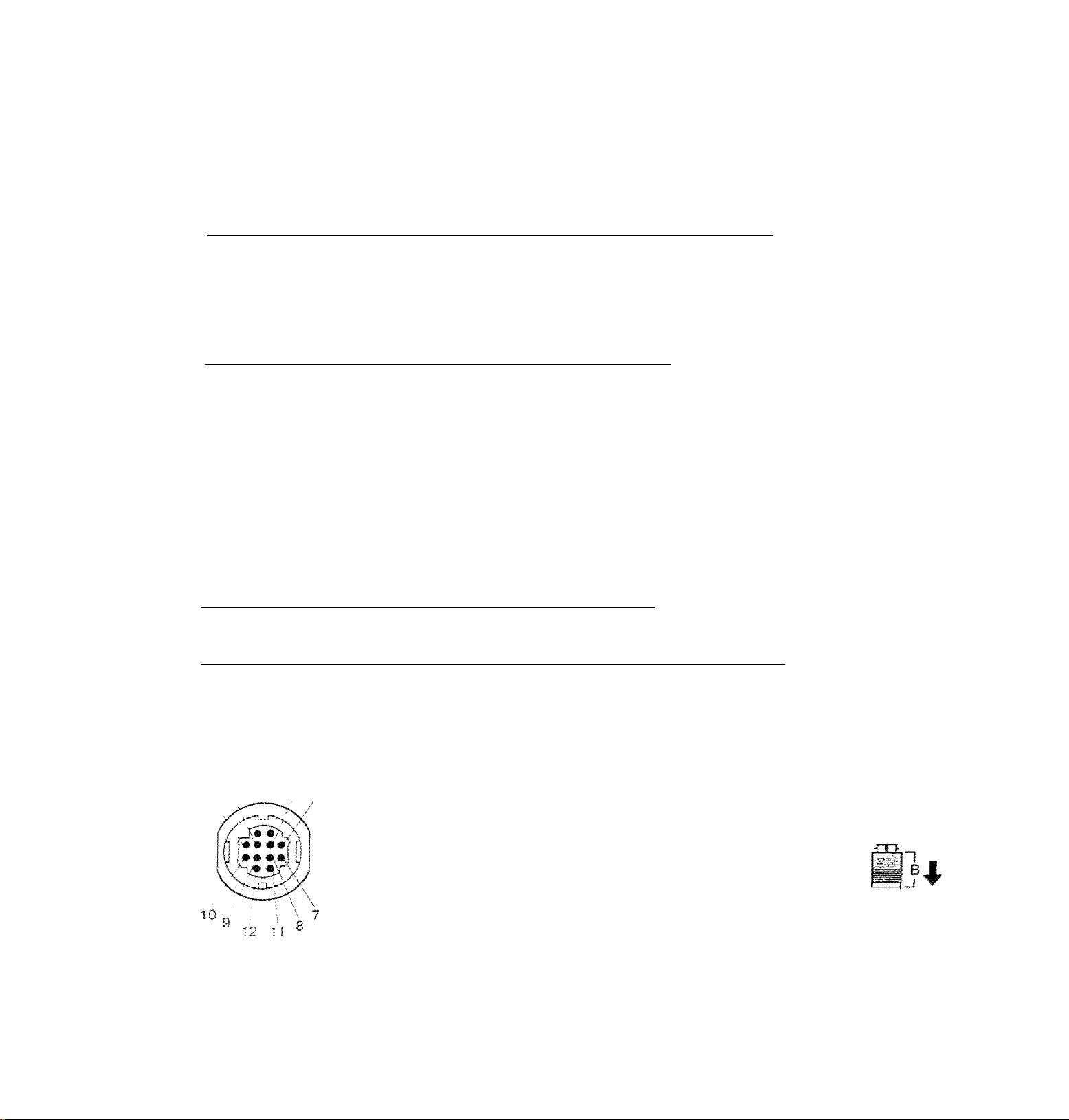
CONNECTING TO THE MULTI-POLE 12-PIN (CONTROL PORT) CONNECTORS (1 and 2)
• II you wish to control the computer with projector's remote control unit, you must connect control port (PS/2, Serial
ADB port! on your computer to projector's control port with a cable (three types of cables provided).
CONTROL PORT
. 2 1
O O O O O
10 9 8 7 6
o o o o o
o o o o o
.15 14131211
pse
Port
DATA
6
8
GND
10
CLK
Serial
Port
TxD
•S- RxD
READY
GND
GND
2 Green input
3 Blue input
4 Sense 2
5 Ground (Horiz. sync.)
6 Ground (Red)
7 Ground (Green)
8 Ground (Blue)
ADB
Port
ADB
2. Pull the portion (B) arrow
CONTROL PORT CABLE
REMOVAL HINT
Disconnect control port cable
with following steps.
1. Hold the portion (A) of the
connector with one hand.
direcion and remove F
connector, i_ If
Pin No./Signa!
9 Non Connect
10 Ground (Vert s;
11 Sense 0
12 Sense 1
13 Horiz. sync.
14 Vert sync,
15 Reserved
11
12
W'L NOTE: The RxD port (5 pin on the Serial Port) is provided on control port 2 connector only. If you control the projed
by computer, you must connect control port 2 connector.
j
Page 11
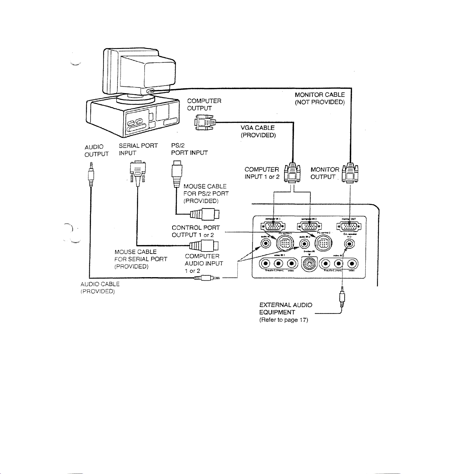
Connecting an IBM-compatible desktop computer
)
COMPUTER
I
MOTE; The hook up shouid be done as per the above illustration. After hook up, turn on the projector, momtor,
computer, in that order.
Page 12
Connecting a Wacintosh desktop computer
COMPUTER
VGA/MAC ADAPTER
Set the dip switches as shown irt the table befow depending on the
RESOLUTION MODE that you want to use before you turn on the
projector and computer.
RESOLUTION MODE .
13" MODE (640 X 480) Ji
16" MODE (S32 X 624) )
1S”MODE (1024X768)
NOTE; The hook up should be done as per the above illustration. After hook up, turn on the projector, monitor,
computer, in that order.
____
SW2
SW1
ON
ON
OFF ON
OFF
ON
SW4
SW3
OFF OFF OFF
OFF
..
li
ON
Gfl
OFF
SW5 SW6
OFF
OFF
OFF
OFF OFF
Page 13
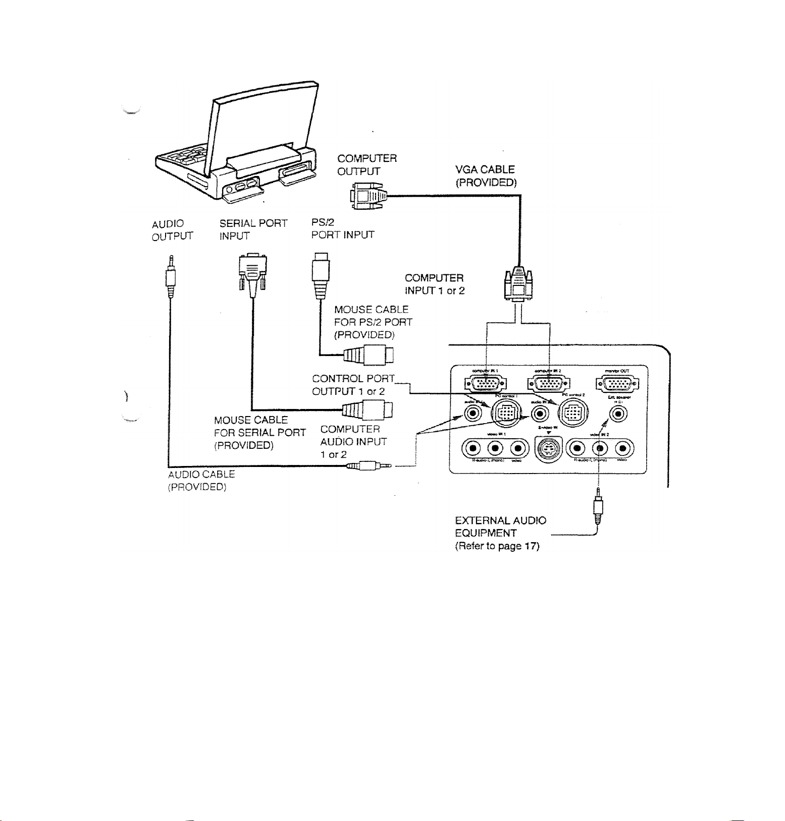
Connecting an IBM-compatible laptop computer
COMPUTER
NOTE; The hook up should be done as per the above iîlustraîion. After hook up, turn on the projector, computer, in
thaï order.
—13 —
Page 14
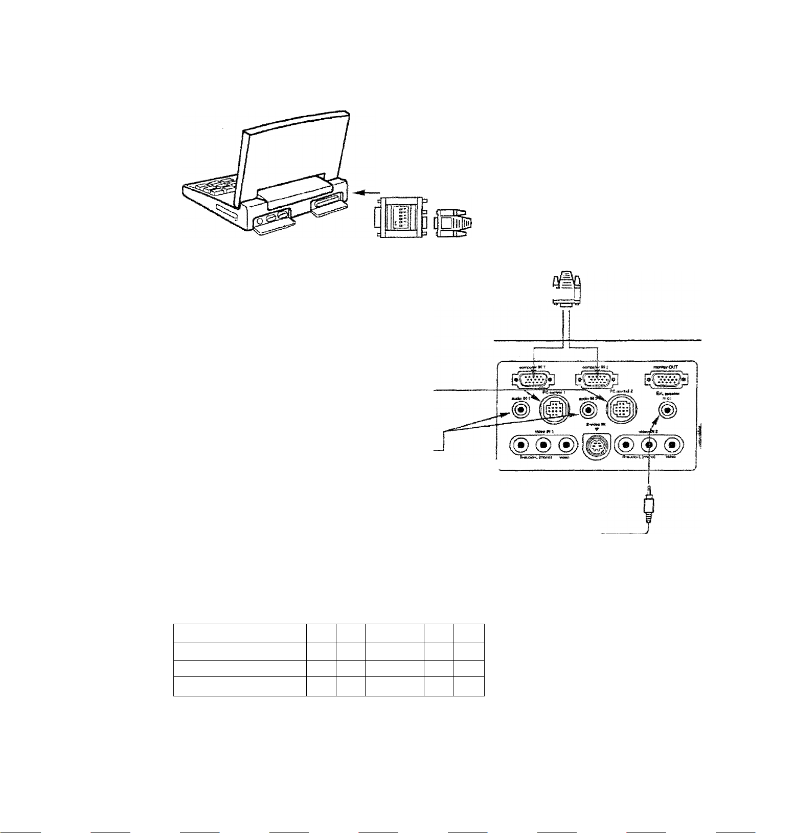
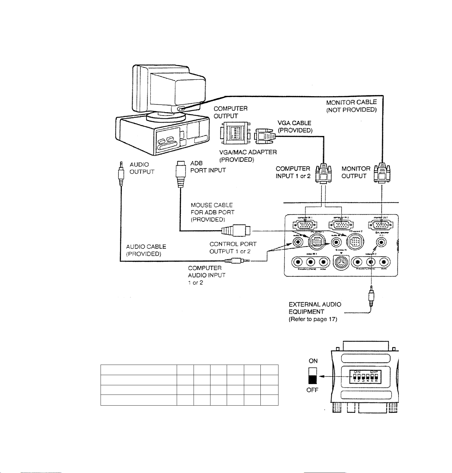
Connecting a Macintosh PowerBook computer
COMPUTER
The Macintosh PowerBook requires the use of the
PowerBook Video Adapter shipped with the PowerBook,
TO POWERBOOK
VIDEO ADAPTER
VGA/MAC ADAPTER
AUDIO
OUTPUT
a
ADB
PORT INPUT
MOUSE CABLE
FOB ADB PORT
(PROVIDED)
(PROVIDED)
COMPUTER
INPUT 1 or 2 nn
- VGA CABLE
(PROVIDED)
CONTROL PORT
OUTPUT 1 or 2
■<aC3î=“'
AUDIO CABLE
(PROVIDED)
Set the dip switches as shown in the table below depending on the
RESOLUTION MODE that you want to use before you turn on the
projector and computer.
RESOLUTION MODE
13" MODE p40 X 480)' ‘
16" MODE .(832 X -e24)
19" MODE (1024 X 768) OFF
COMPUTER
audio INPUT1 or 2
SW2
SW1
ON
ON
OFF
.ON
ON
SW3
OFF
OFF
ON
SW4
OFF
OFF
SW5
OFF
OFF
OFF
SW6
OFF
OFF
OFF
EXTERNAL AUDIO
EQUIPMENT
(Refer to page 17)
VGA/MAC ADAPTER
J1
ON
OFF
H
T®--------Î5JP-
■ fiiiii
ill I II
lily U i
NOTE. The hook up should be done as per the above illustration. Ater hook up, turn on the projector, computer
that order.
Page 15

ÇONNEQTING the YIDJOJQUIf^Nl
nOMiaECTÎPIG TO THE AV INPUT 1 JACKS
t to the video and audio outputs of a VCR, video disc player, video camera, satellite TV tuner or other AV
eQw.y^ient.
• Connect audio/video outputs from external sources to these input jacks using the audio/video cable.
• tf the audio signa! from the AV equipment is stereo, be sure to connect the right and left channels to the respec^ve right
and left audio input jacks.
• If the' externa} audio signal is monaural, connect it to the left jack.
S-VHS FORMAT VCR CONNECTíON
The AV 1 input includes an extra video input jack marked S-VIDEO to allow connection to an S-VHS format VCR that has
separate Y/C video signals. The S-VIDEO jack has priority over the VIDEO jack,
CONNECTING TO THE AV INPUT 2 JACKS
Connect to the video and audio outputs of a VCR, video disc player, video camera, satellite TV tuner or öfter AV
equipment.
• Connect audio/video outputs from external sources to these input jacks using the audio/video cable.
• if the audio signal from the AV equipment is stereo, be sure to connect the right and left channels to the respective right
and left audio input jacks.
• If the external audio signal is monaural, connect it to the left jack.
Page 16

Connectifig the Video Equipment
VIDEO EQUIPMENT
Video Cassette Recorder
DVD Player
Video Disc Player
Satellite
TV Tuner
L R
AUDIO
OUTPUT
VIDEO
OUTPUT
S-VHS VCR
Etc...
NOTE; The hook up should be done as per the above illustration. After hook up, turn on the projector, video equipment,
in that order.
Page 17

CpNNJCTJNG
f-riMNECTING TO THE EXT. SP. JACK (3.5mm mini stereo tvDel
^ jack outputs stereo speaker sound which viewing on screen. If you use externa! speaker system, connect stereo
external speaker jack. Internal speaker sound is disconnected when speaker jack is connected.
T PCecr»atg
f
EXTERNAL
SPEAKER SYSTEM
•)©®)®(00
TTSS^TFS^T"
H'^iuiSo^ifttarOj "
17-
Page 18

r
OPERATION OF CONTROLS
FRONT
INDICATORS
Page 19

lamp replacement inoicator
D®
Light is orange when projecBon iamp is nearing end of service We.
A temperature warning indicator
» Flashes red when internal oroiector temn^
Flashes red when internal projectoTTernperaiure is too high.
BEADY INDICATOR
©
Light is green when projector lamp is ready to be turned on.
A lamp POWER INDICATOR
Light is dim when the profector is on
LigM is bnghtened when the projector Is in stand-by mode.
LAMP POWER ON/OFF SUTTON
Used to turn projector on or off.
©
^ COMPUTER SELECT BUTTON
^ Used to select computer mode (Computer 1 or Computer 2).
VIDEO SELECT BUTTON
Used to select video mode Video 1 or Video 2).
0 VOLUME BUTTONS
Used to adjust volume.
A MENU BUTTON
This button will activate the MENU operation.
projector’s sking in MENU buttons and'the SELECT button to make adjustments to the
'II AUTO IMAGE BUTTON
Used to operate the AUTO IMAGE function.
ZOOM BUTTONS
Used to operate power zoom lens.
FOCUS BUTTONS
Used 10 operate power focus system.
POINT UP/DOWN/LEFT/RIGHT BUTTONS
£ttOT?(Up"DOWN^LEFT^r pressing these
^ SELECT BUTTON
This button has different functions depending on when used. This button is used to execute the item selected to
increase or decrease the values in certain items such as CONTRAST or BRIGHTNESS,
> tfi.
Page 20

BEAR OF THE PROJECTOH j
COMPUTER JNPUT-1 TERMINAL
Used to corsnect a computer to the projector.
COMPUTER INPUT-2 TERMINAL
m
Used to connect a computer to the projector.
MONITOR OUTPUTTERMIIlAi
Used tc connect a monitor to the profector.
COMPUTER AUDIO INPUT-1 JACK
mini stereo type
Used to connect a computer audio input to the
projector.
CONTROL PORT-1 CONNECTOR
m
Used to connect a mouse cable to the projectof
COMPUTER AUDIO INPUT JACK 2
mini stereo type
Used to connect a computer audio input to the
projector.
CONTROL PORT-2 CONNECTOR (SERIAL PORT)
m
Used to connect a mouse cable to the projector.
NOTE: Control port-2 connector can be also used
as serial port.
AUDIO INPUT-1 JACKS
Used to connect an audio input to the projector.
¥IDE0 INPUT-1 JACK
Used to connect a video source to the projector.
S-VIDEO INPUT JACK
Used to connect a S-VHS video source to the proj
AUDIO INPUT-2 JACKS
Used to connect an audio input to the projector.
VIDEO WPUT-2JACK
Used to connect a video source to the projector.
EXT. SP. JACK (3.5 mm mini stereo type)
Used' to connect an external speaker system.
Page 21

--------
is remote control unit not only operates the nm;« . .
'^SO be used as a wireless mouse for a PC QnfinuKÎ
buttons are used for wireless mouse operation and four
The wireless mouse is active when the PC a ira ■
the screen. When the projector menu is ‘displayed on
. instead of the cursor, the wireless mouse cann^f k screen
£&Ë^ÜOnof^ote control
'^auiioi De Used.
NOTE: To use the unit as a PC wirelesa
projector to the PC with the attached cahl^' ^onnect the
the projector are trarrsmitted to the PC ff from
control unit to be used as a PC remote
■CONNECTING THE PROJECTOR “L™"®'*- »0
the connection.) ^ Pages 10 to 14 tof
laser radiation
DO NOT STARE INTO BEAM
Diode Laser
c5 0 miHiwaîî max.'output
Wavelength 630-680 nm
Class ilia Laser Product
FRONT
I
See caution when operating the Laser remote
control. Laser light can cause harm if projected at
the human eye. Observe the cautions on the Laser
Warning label located on the rear of the remote
control. Do not point the laser directly into any
person’s eyes.
— 21
Page 22

D. ZOOM BUTTON
Used to select digital zoom function.
NORMAL BUTTON
Use to reset to norma! picture adjustment preset by factory.
AUTO IMAGE BUTTON
e
Used to operate AUTO IMAGE function.
BLANK BUTTON
e
Used to change the screen into black image.
MENU BUTTON
©
This button will activate the MENU operation. Use this button, the POINT UP/DOWN/LEFT/RiGHT button and th
SELECT button to make adjustments to the projector’s setting in MENU operation.
LAMP POWER ON/OFF BUTTON
Used to turn the projection iamp on or off.
FREEZE BUTTON
O
Use this button to freeze on-screen image.
P-TIMER BUTTON
o
Used to operate the P-TlMER function.
MODE BUTTON
©
Used to select video source. (Computer 1. Computer 2. Video 1 or Video 2 Input}
FOCUS BUTTONS
Used to operate power focus system.
iP VOLUME BUTTONS
Used to adjust volume.
ZOOM BUTTONS
Used to operate power zoom lens.
(R SOUND MUTE BUTTON
Used to mute sound.
IFI JOYSTICK
(POINT UP/DOWN/LEFT/RIGHT BUTTON)
When used as a remote for the projector control.
To select an item on the MENU that you want to adjust. To select an item, move the arrow by move the Joystic
forward, backward, leñar right.
When used as a wireless mouse
Acts like a mouse. Move the joystick in the direction that you want to move the screen cursor. The further ya
move the joystick in any direction, the faster the cursor will move.
SELECT (LEFT CLICK) BUTTON
©
When used as a remote for the projector control.
This button has different functions depending on when used. This button is used to select menu items.
When used as a wireless mouse
This button has the same function as the left button in a PC mouse.
RIGHT CLICK BUTTON
This button has the same function as the right button in a PC mouse. Pressing this button does not affect art
operation when in MENU mode.'
DRAG LEFT/RIGHT BUTTONS
©
Use this button and the joystick to drag a selected screen object. Press and release the Drag Lett or Right butto,
the button giows and the remote control is in Drag mode. Move the joystick in the direction that you want to dr®
the screen object. Press and release a second time to drop the object at the new screen location.
LASER BUTTON
©
Press and hold to activate the laser pointer.
Page 23

REMbtgCONiTOIcBAl
rERMlNSJAlsLATIOfl
USING REMOTE CONTROL
Point the remote control toward the projector’s front or rear receiver windows whenever using the remote control,
jytaximum operating range for the remote control is about 16,4’ {5m) and 60 ° front and rear of the projector.
To insure safe operation, please observe the following precautions:
A
• Use (2) AAA type alkaline batteries.
• Change two batteries at the same time.
• Do not use a new battery with a used battery.
® Avoid contact with water.
• Do not drop the remote controi unit.
• If batteries have leaked on the remote control, carefully wipe the case
clean and load new batteries.
■23-
Page 24

c
The projector has two types of operation; DIRECT OPERATION and MENU OPERATION. DIRECT OPERATION
allows you to operate the projector by using one button without showing the MENU. In MENU OPERATION mode,
you display menus where you can adjust the projector's settings. Follow the instruction for each control.
BmBOTOPBnknoH
CONTROL THE PROJECTOR
ADJUST ITEM ,
POWER ON/OFF
MODE SELECT
SOUND VOLUME
SOUND MUTE
ZOOM
FOCUS
DIGITAL ZOOM
NORMAL PICTURE
NO SHOW
TOP CONTROL
^ -OF THE-PROJECTOR-^^^S
POWER ON-OFF BUTTON
COMPUTER BUTTON
VIDEO BUTTON
VOLUME (+) and ( - ) BUTTONS VOLUME (+) and ( ” ) BUTTONS
NOT AVAILABLE
ZOOM (/\) and (V} BUTTONS ZOOM (^) and (V) BUTTONS
FOCUS i/\) and (v) BUTTONS
NOT AVAILABLE
NOT AVAILABLE
NOT AVAILABLE ;
J REMOTE CONTROL UNIT
POWER ON-OFF BUTTON
MODE BUTTON
MUTE BUTTON
FOCUS (A.) and (n/) BUTTONS
D. ZOOM BUTTON
SELECT BUTTON
RIGHT CLICK BUTTON
POINT (UP/DOWN/LEFT/RIGHT) 1
BUTTON j
NORMAL BUTTON
BLANK BUTTON
P. TIMER
FREEZE PICTURE
AUTO IMAGE
NOT AVAILABLE
NOT AVAILABLE
AUTO IMAGE BUTTON
P. TIMER BUTTON
FREEZE BUTTON
AUTO IMAGE BUTTON
Page 25

’■•TOP CONTROL '■■■''
.#bEfraE'iRiR03ECT0R ' :■ REMOTE CON. hOL LN»T
■^öe'select::^^^'
L—
------
-------------------
MENU BUTTON
POINT LEFT/RIGHT BUTTONS
SELECT BUTTON
POINT UP/DOWN BUTTONS
SELECT BUTTON
1 nOMPüTER/VIDEO MODE
: adjust ITCM ■
SOUND
SOUND VOLUME
SOUND MUTE :
language
SETTING
blue back
display
CEILING i
REAR
SPLIT WIPE
LAMP AGE
TOP CONTROL
. OF THE PROJECTOR _
MENU BUTTON
POINT LEFT/RIGHT BUTTONS
SELECT BUTTON
POINT UP/DOWN BUTTONS
SELECT BUTTON
MENU BUTTON
POINT LEFT/RIGHT 8UTK5NS i
SELECT BUTTON
POINT UP/DOWN BUTTONS
SELECT BUTTON
MENU BUTTON
POINT (LEFT/RfGHT) BUTTON
SELECT BUTTON
POINT (UP/DOWN) BUTTON
SELECT BUTTON
-;WiMdTE:CONT«OL’:UNIT : ,
MENU BUTTON
POINT (LEFT/RIG.HT) BUTTON
SELECT BUTTON
POINT (UP/DOWN) BUTTON
SELECT BUTTON
MENU SUTTON
POINT CLEFT/RIGHT) BUTTON
SELECT SUTTON
POINT (UPiOOWN) BUTTON r
SELECT BUTTON
2. VIDEO MODE
: ADJUST ITEM
COLO« SYSTEM
PICTURE IMAGE
COLOR
TINT
CONTRAST
BRIGHTNESS
SHARPNESS
PICTURE SCREEN
WIDE
regular
TOP CONTROL
, OF THE PROJECTOR
MENU BUTTON
POINT leftt^ight buttons
SELECT BUTTON
POINT yp/OOWN BUTTONS
SELECT BUTTON
MENU BUTTON
POINT LEFT/RIGHT BUTTONS
SELECT BUTTON
POINT UP/DOWN BUTTONS
SELECT BUTTON
■ REMOTE CONTROL UNIT
MENU BUTTON
POINT (LEFT^IGHT) BUTTON
SELECT BUTTON:
POINT (UP/DOWN) BUTTON
SELECT BUTTON
MENU BUTTON
POINT (LEFT/RIGHT) BUTTON
SELECT BUTTON
POINT (UP/DOWN) BUTTON
SELECT BUTTON:
Page 26

3. COMPUTER mODE
ADJUST ITEM
COMPUTER SYSTEM
-
■■■■ i
AUTO IMAGE
FINE SYNC
TOTAL DOTS .
POSITION
PICTURE IMAGE
FINE SYNC
TOTAL DOTS
WHITE BALANCE
CONTRAST
BRIGHTNESS
PICTURE POSITION
‘-top CONTR6i?l??^^^^
•-•vOF-tHEiPROjECTdlT^r^;::.'^^^
MENU BUTTON
POINT LEFT/RIGHT BUTTONS
SELECT BUTTON
POINT UP/DOWN BUTTONS
SELECT BUTTON
MENU BUTTON
POINT LEFT/RIGHT BUTTONS
SELECT BUTTON
POINT UP/DOWN BUTTONS
SELECT BUTTON
MENU BUTTON
POINT LEFT/RIGHT BUTTONS
SELECT BUTTON
POINT UP/DOWN BUTTONS
SELECT BUTTON
MENU BUTTON
POINT LEFT/RIGHT BUTTONS
SELECT BUTTON
POINT LEFT/RIGHT/UP/DOWN
BUTTONS
SELECT BUTTON
'-REMOTE CONTROL UNfr
MENU BUTTON
POINT (LEFT/RIGHT) BUTTON
SELECT BUTTON
POINT (UPCiOWN) BUTTON
SELECT BUTTON
MENU BUTTON
POINT (LEFT/RIGHT) BUTTON
SELECT BUTTON
POINT (UP/DOWN) BUTTON
SELECT BUTTON
MENU BUTTON
POINT (LEFTffilGHT) BUTTON
SELECT BUTTON
POINT (UP/DOWN) BUTTON
SELECT BUTTON
MENU BUTTON
POINT (LEFT/RIGHT) BUTTON
SELECT BUTTON j
POINT (LEFT/RiGHT/UP/DOWN)l
BUTTON
SELECT BUTTON
PC ADJUSTMENT
PICTURE SCREEN
TRUE
DIGITAL ZOOM"
t
S
MOTES:
1
.if you switch to DIRECT operation by pressing a DIRECT operation button wniie in MENU mode, the menu?
will disappear and the MENU operation will end.
2. You can use the REMOTE CONTROL UNIT or the TOP CONTROL OF THE PROJECTOR to operate the'
MENU operation.
MENU BUTTON
POINT LEFT/RIGHT BUTTONS
SELECT BUTTON
POINT UP/DOWN BUTTONS
SELECT BUTTON
MENU BUTTON
POINT LEFT/RIGHT BUTTONS
SELECT BUTTON
POINT UP/DOWN BUTTONS
SELECT BUTTON
POINT LEFT/RIGHT/UP/DOWN
BUTTONS
MENU BUTTON
POINT (LEFT/RIGHT) BUTTON
SELECT BUTTON
POINT (UP/DOWN) BUTTON
SELECT BUTTON
MENU BUTTON
POINT (LEFT/RiGHT) BUTTON
SELECT BUTTON
POINT (UP/DOWN) BUTTON
SELECT BUTTON
SELECT BUTTON
RIGHT CLICK BUTTON
POINT (UP/DOWN/LEFT/RIGHT)
BUTTON
Page 27

USING THE PROJECTOR
c
art the projector to a source (Computer, VCR, Video Camera, Video Disc Player, etc.) using the appropriate
termS on the rear of the projector {See "CONNECTING THE PROJECTOR" section on pages 10-17).
ort the projector’s AC power cord into a wall outlet and turn the MAIN ON/OFF switch (located on the rear of the
pr^Sr) to the ON position. The LAMP POWER indicator will light RED. the READY indicator will light GREEN.
the LAMP POWER ON/OFF button on the remote control unit or on the
to ON, The LAMP POWER indicator tight will dim and the cooling fans will
The wait display appears on the screen and the count-down starts
°
2(5 19-18
A
WOTE' TEMPERATURE WARNING INDICATOR flashes red, the projector will automaticafiy turn off.
” " Wait at least 5 minutes before turning the projector on.
- ..1)- The signal from the source appears after 30 seconds.
CAUTION:
THIS PROJECTOR USES A SID LAMP. TO EXTEND THE UFE OF THE LAMP, ONCE YOU HAVE TURNED
rr ON, WAIT AT LEAST 5 MINUTES BEFORE TURNING IT OFF.
If the TEMPERATURE WARNING INDICATOR continues to flash, follow the procedures below:
(1) . Press LAMP POWER ON/OFF button to OFF.
(2) ' Check the air filter for dust accumulation.
(3) . Remove dust with vacuum cleaner (See "AIR FILTER CARE AND CLEANING” section on page 47.)
(4) . Press LAMP POWER ON/OFF button to ON.
If the TEMPERATURE WARNING INDICATOR still continues to flash, call your authorized dealer or service
Î
station.
TO TURN OFF THE PROJECTOR
Press the LAMP POWER ON/OFF button on the remote control unit or on the
oroiector. The "Power off ?” appears on the screen. Press again the LAMP POWER
ON/OFF button to turn OFF the projector. The LAMP POWER indicator will light bright
and READY- indicator will turn off. The cooling fans will operate for 1 minute alter the
orcsector is turned off. (During this "cooling down" period, the projector cannot be
turned on,I The READY indicator will light green again and the projector may be turned
on by pressing the LAMP POWER ON/OFF button. To power down completely, turn
!ne MAIN ON/OFF switch (located on the rear of the projector) to the OFF position.
Power off:?:
DIRECT OPERATION MODE SELECT (Top control)
Press the COMPUTER button located on the projector to select Computer 1 or , - Computer 2 Input. The "Computer 1” or "Computer 2" display will appear on the
screen for a few seconds.
Press the VÍDEO button located on the projector to select Vdeo 1 or Video 2 input -
I ne 'Video 1 ’’ or "Video 2" display will appear on the screen for a few seconds. ¿TYideo 1
MODE SELECT (Remote control unit)
MODE button located on the remote control unit to seieci Computer 1,
^-c.Mpwisr 2. Videori or Video 2 input. The "Computer 1”, "Computer 2", "Video T or a ■
^ Video 2 display will appear on the screen for a few seconds. |
-SCorri'pbtsr.
— 27-
f'Video 2'
• V VidOT
1
Page 28

^Bl
SOUND VOLUME ADJUSTMENT
Press the VOLUME buttons (located on remote control unit or on the projector) to
adjust the volume. The volume display will be displayed on the screen tor a few
seconds.
Pressing volume (+) will increase volume and increase the number on the screen.
Pressing volume (-) will decrease volume and decrease the number on the screen.
SOUND MUTE FUNCTION
Pressing the MUTE button on the remote control unit will mute audio. Press the
MUTE button again to restore audio to its previous ievel. Hie mute display will be
displayed on the screen for a few seconds.
ZOOM ADJUSTMENT
Press the ZOOM ( A. ) or ( %/ ) buttons (located on remote control unit or on the projector) to
obtain your desired picture size.
For a larger picture, press (A) and for a smaller picture, press (\у).
FOCUS ADJUSTMENT
Press the FOCUS ( A ) or (\/ ) buttons (iccated on remote control unit or on the projector) for a
sharper, crisper picture.
DIGITAL ZOOM FUNCTtON
Press the D. ZOOM button on the remote control unit. The message “Quif is displayed to
indicate Digital Zoom mode. Digital zoom mode can be adjust the image size or pan the image.
To expand the image size, press SELECT (LEFT CLICK) button. The image is magnified by
degrees (Expand function).
To compress the image size, press RIGHT CLICK button. The size of image is reduced by
degrees {Compress function).
To pan the image, press POINT UP/DOWN/LEFT/RIGHT (JOYSTICK) button(s). The image
move to the direction indicated (panning function).
To cancel Digital Zoom mode, press other buttons (except BLANK button).
NORMAL PICTURE FUNCTION
The normai picture ievel is factory preset on the projector and can be restored anytime by
pressing the NORMAL button on the remote control unit The "Normal" display will be displayed
on the screen for a few seconds.
NO SHOW FUNCTION
Press the BLANK button on the remote control unit. The screen will change into black image and
the "NO SHOW” is displayed on the screen for a few seconds.
This function is cancelled when the BLANK button is pressed again or any other function button
------
is-oressed,
_
______________
___________
_
P-TIMER FUNCTION
Press the P-TiMER button on the remote control unit The timer display "00:00" appears on the
screen and the timer starts to count the time (00:00 to 59:59).
Press again the P-TiMER button to stop the timer. Then press the P-TIMER button to cancel the
P-TIMER function.
FREEZE PICTURE FUNCTION
Press the FREEZE button on the remote control unit, and the picture will remain on-screen. This function is can^
when the FREEZE button is pressed again or any other function button is pressed.
-•Tit
Volume
..
—■
Quit
B|
....................
О
-Focui
Norm«
No she
00:0
NOTE: Your computer or video equipment is not affected by this function, and will continue to run.
AUTO IMAGE FUNCTION
Press the AUTO IMAGE button, on the remote control unit or on the projector. The liem(s) indicated "ON" in the f
IMAGE FUNCTION are adjusted automaticaily.
if all the imms ir: AUTO i«f.4GE FUNCTION are "OFP, AUTO IMAGE SETTING display appears, if you wish to op
the AUTO IMAGE FUNCTION, perform the steps 3 - 9 of "AUTaiMAQE FUNCTiON” seotion on page 3S.
Page 29

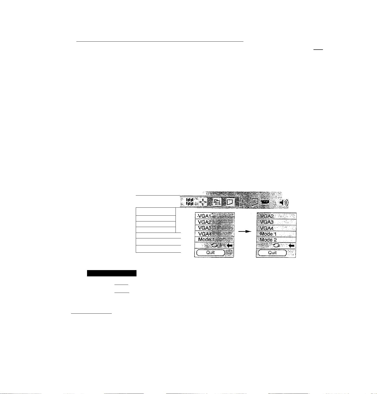
I R/fgNMSËlf^ATION:
in OPERATION mode, you display menus where you can adjust the pro|ector*s setfiifs. You can use the TOP
nNTROL OF THE PROJECTOR or the REMOTE CONTROL UNÎT.
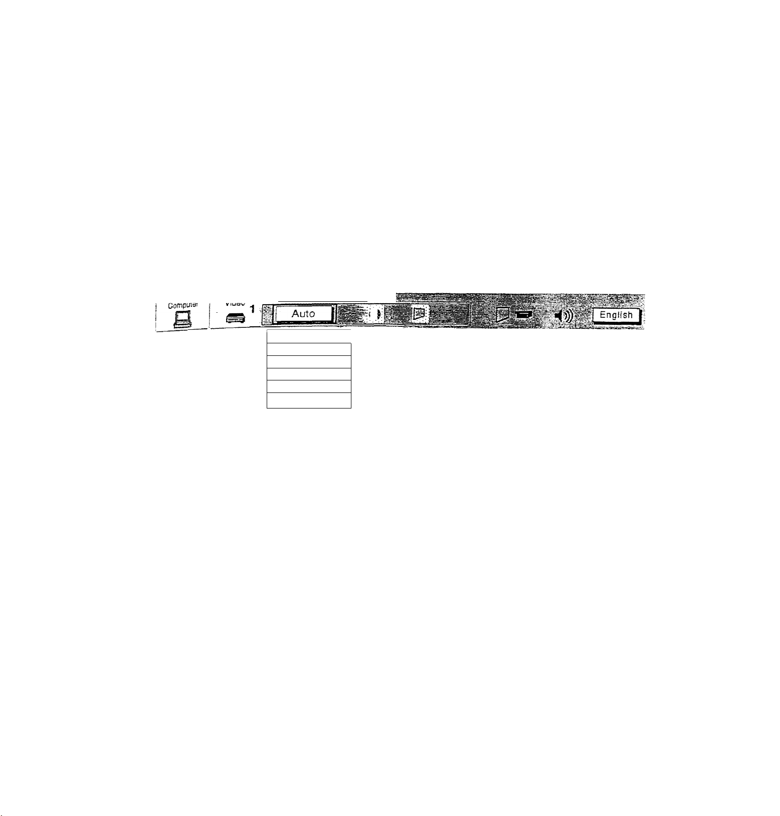
1. Press the MENU BUTTON and the MAIN MENU DISPLAY dialog box will appear.
2 Press the POINT LEFT/RlGHT BUTTONjsl to select Computer or \1deo and press the SELECT BUTTON. Another
dialog box MODE DISPLAY will appear.
3 Press the POINT DOWN BUTTON and a red arrow will appear.
Move the arrow to the mode you want (computer 1. computer 2, video 1 or video 2) to use by pressing the POINT
UP/DOWN BUTTONts) and then press the SELECT BUTTON.
MAIN MENU DISPLAY
i ComotAer
1
a
I
Computer 1 4» I
Compirter2 MODE DISPLAY
Video
Video 1
Video 2
Video
r.'i Auto fi'.ii
MAIN MENU DISPLAY
CenptRar
n I'[eTs
MODE DISPLAY
•29-
....
Page 30

up
SOUMP ADJUSTMENT
You can adjust the sound volume and sound mute used in the MENU.
1
. Press the MENU BUTTON and the MAiN MENU DISPLAY dialog box will appear.
2. Press the POINT LEFT/RIGHT BUTTON{s) to select SOUND and press the SELECT BUTTON. Another dia
SOUND ADJUST DISPLAY will appear.
3. Press the POINT DOWN BUTTON and a' red arrow will appear.
4. Move the arrow to an Item that you want to adjust by pressing the POINT UP/DOWN SUTTON (s).
5. To increase the sound volume, point the arrow to A and then press the SELECT BUTTON. To decrease th€
volume, point the arrow to V and then press the SELECT BUTTON.
6
. To mute the sound, point the arrow to Mute arjd then press the SELECT BUTTON, The mute display is chani
from Off and mute the sound.
7. To quit the MENU, point to Quit and then press the SELECT BUTTON,
ulSi
LANGUAGE ADJUSTMENT
MAIN MENU DISPLAY
SOUND ADJUST
DISPLAY
.
....
"f
A language used in the MENU is selectable from among English, German, French, Italian, Spanish and Japanes-
1. Press the MENU BUTTON and the MAIN MENU DISPLAY dialog box will appear.
2. Press the POINT LEFT/RIGHT BUTTONIs) to select LANGUAGE and press the SELECT BUTTON. Aoi
dialog box LANGUAGE SETTING DISPLAY will appear.
3. Press the POINT DOWN BUTTON and a red arrow will appear.
4. Move the arrow to the language you want to use by pressing the POINT UP®OWN BUTTON(s) and then p
the SELECT BUTTON.
5. The setting is permanently held even if the MAIN ON/OFF is switched off.
MAIN MENU DISPLAY
Video
Computer,
VGA
.
....................
“ .■ . -■ 'j.—il^SSSSS
LANGUAGE SETTING DISPLAY
■ LANGiiASi
Frangals
Hafiano fTT,;
■Espanol
gtish j
Page 31
CmORSmiMmiCT^
This proiBCtor is compatible with the five malar
PAL-M (COLOR SYSTEMS), ¡t automatically ad n atarrdards: Pal SPnA,,
PAL-m- Hovwvif, » the video signa/ is LltnL “ “f'«»> »> P«fcf4;K»^i^. ^TSC 4.43 and
reproduce the proper video Image. I„ case Ws happen" ^ fomiÍ th^™?
Signal fcmiat. PPnns, this ^ omat the prqectcr may „¿
r-r 4 fh -w • ^ specific broadcast
Hä
1. Connect the video equipment to the PROJFrrna
2. Set MODE SELECT to 'VIDEO MODE’ ' fhem on projector fir t
COLOR SYSTEM DISPLAY will appear. The current COLOR SYSTEM is displayed in toe system window,
box
5, Press
7
The setting changed remains effective until the MAIN ON/OFF switch is turned off.
toe POINT DOWN BUTTON and a red arrow wifi appear.
the current COLOR SYSTEM, press the POINT UP/DOWN BLfTTON(s) to move the arrow to a
hLrable sV- then press the SELECT BUTTON.
MAIN MENU DISPLAY
"-^YSTEM-T^^T"^g^
Auto
:3t|
PAL f«.S
SECAM
NTSC
,lsrrSC4.43
;.PAL-M
■'.•Í 1
COLOR SYSTEM
DISPLAY
•?' -
•31
Page 32

PICTURE IMAGE ADJUSTMENT (VIDEO MODEl
Although picture adjustments have been preset at the factory, you may want to change the setting-
1
. Press the MENU BUTTON and the MAIN MENU DISPLAY dialog box will appear.
2. Press the POINT LEFT/RIGHT BUTTON(s) to select IMAGE and press the SELECT BUTTON. Another dialc
IMAGE ADJUST DISPLAY will appear. This shows the current picture settings.
3
. in this dialog box. you can adjust the settings by increasing or decreasing the levels shown as numbers. The
and the range of the levels that you can adjust are summarized in the table below.
4
. Press the POINT DOWN BUTTON and a red arrow will appear.
5
. Move the arrow to an item that you want to adjust by pressing the POINT UP/DOWN BUTTON(s).
6
. To increase the level, point the arrow to A and then press the SELECT BUTTON. To decrease the level, po
arrow to V and then press the SELECT BUTTON,
7. You may want to store the settings in the memory so that you can recall them iater. To store the settings,
the arrow to Stored and then press the SELECT BUTTON. When you have stored the settings. ”OK ?” Is disj
for confirmation.
8
. Move the arrow to Yes and then press the SELECT BUTTON. The stored settings are permanently held €
the MAIN ON/OFF is switched off.
9
. To quit the MENU, move the arrow to Quit and then press the SELECT BUTTON.
10. If you do not want to store the settings, move the arrow to Quit and then press the SELECT BUTTOh
settings changed remains effective until the MAIN ON/OFF switch is turned off.
11
. To recall the settings from the memory that you have stored, move the arrow to Reset and then prei
SELECT BUTTON. When you have reset the settings, ”OK T is displayed for confirmation. Move the an
Yes and then press the SELECT BUTTON. You can adjust the settings again if needed.
NOTE; TINT’ will be skipped in the PAL , SECAM and PAL-M mode.
MAIN MENU DISPLAY
Computer
COLOR
IMACaEj^CT
IMAGE
ADJUST DISPLAY
TABLE OF PICTURE IMAGE ADJUSTMENT
DECREASES
_______
0 ► 63 INCREASES
«(1))
i
English
TINT
CONTRAST
BRIGHTNESS
SHARPNESS
MORE PURPLE 0-
LIGHTER 0^ 63
DARKER
SOFTER
0^ 63
0
-*- 63
63 MORE GREEN
DEEPER
BRIGHTER
SHARPER
Page 33

ADJUSTMENT (VIDEO MODE)
function, which enables you to view a wider vii
This
/¡DE function
'^This projector is able to project not only a normal video imsno / ■«.
by compressing 4x3 image. This feature enable vou tn or,-® ^ ^ aspect raao) hi.
either to WIDE or to REGULAR screen mode ““ng pictures like lei ^ image
1
. Press the MENU SUTTON and the MAIN MENU DRPi a v .a-
2
. Press the POINT LEFT/RIGHT BUTTQN(s) to ^PPear
tax SCREEN ADJUST DISPLAY will appear P^ess th7SELECT m ^
3 Press the POINT DOWN BUTTON and a redarro^ win . BUTTON. Another diafoo
4
. To switch to ’'Wide" mode, move the arrow to Wiri^ k ®
the SELECT BUTTON. by Pressing the POINT UP/nn,A/K, .
5
. To switch to "rngulaf mode, move the arrow to Rea, ^U^ON(s) and then press
press the SELECT BUTTON. by pressing the point , ^
6
The -Wide- settings remains effective until me MAIN ON/OFR ■ BUTTON(s, and then
MAIN MENU DISPLAY
wider video image.
"ama mages. You can switoh
switch is turned Off.
r i ReguianT
[i-; Wide-
SCREEN ADJUST
DISPLAY
— 33 —
Page 34
COMPUTER SYSTEiyt SELECT {COMPUTER MOPE)
This projector is adjustable to different types of computer display signals based on VGA. SVGA or XGA (Si
"COMPATIBLE COMPUTER SPECIFICATIONS” on the next page). If you set MODE SELECT to "COMPUTER". tJ
projector will automatically process the incoming signal and project the proper image without any special setBn
Although this will work in most cases, you may be required to manually set the projector for some computer signals.
the computer image is not reproduced properly, try the foiiowir?g procedure and switch to the computer display moc
that you want to use.
1
. Connect the COMPUTER to the PROJECTOR, and turn them on projector first.
2. Set MODE SELECT to "COMPUTER MODE (1 or 2)". This shows the current display mode initially detected by th
projector in the system window. And "Current mode” display appears.
NOTE: 1. If the projector cannot discriminate or detect the input signal from the computer, the "Go PC adj." displa
appears,
NOTE: 2. If no input signal from the computer, the "No signal" display appears on the screen,
3. Press the MENU BUTTON and the MAIN MENU DISPLAY dialog box will appear.
4. Press the POINT LEFT/RIGHT BUTTON(s) to select SYSTEM and press the SELECT BUTTON. Another dialoc
box COMPUTER SYSTEM DISPLAY will appear.
5. Press the POINT DOWN BUTTON and a red arrow will appear.
6. If you want to change the current display mode, move the arrow by pressing the POINT UP/DOWN BUTTON(s)
select one of the modes.
7. Press the SELECT BUTTON to change the display mode.
8. To quit the MENU, move the arrow to Quit and then press the SELECT BUTTON.
МАШ MENU DISPLAY
Video
4^-
COMPUTER
SYSTEM:
DISPLAY
CURRENT MODE
DISPLAY
Clirrefttmode
H-Syncfreq, [ 36S j
V-Sync freq. f ed.o |
PC ADJUSTMENT
This is a special function that may be used when a computer image is not reproduced properly. (See the pages 39 42 for more detail.)
II VGA 1
VGA1
VGA2
VGA3
VGA4
" О
( Quit
im
r
r
]
1
) =
When the mark {O ) is displayed as BLACK,
computer system mode will be available on the
next page. Move an arrow to the mark (-Gi- )
and press the SELECT BUTTON to show
computer system mode described on the next
page.
English
I i
Page 35

^-nMPATIBLE COMPUTER SPECIFICATIONS
;e
ON-SCREiE N
3
II
e
DISPLAY,
VGA1 640 X 480
VGA2
VGA3
VGA4
VGA5
VGA6
VGA7
MAC LC13
MAC 13
SVGA
1
SVGA2
SVGA3
SVGA4
SVGAS
SVGAS
SVGA?
SVGAS
SVGAS 800 X 600
SVGA10 800 • 600 32.70
SVGA11
MAC 16 832 >• 624 49.72 74.55
XGAt
XGA2 1024 X 768
XGA3
XGA4
XGA5
XGA6
XGA7 1024 X 768
XGA
8
XGA9 1024 X 768
XGA10
XGA11 1024 X 768
XGA12 1024 X 768
XGai3 1024 X 76S
XGA14
XGA15
MAC19
. . R^QiyjpN
i
720 X 400
640 X 400
640 X 480
640 X 480
640 X 480
640 X 480 43.269
640 X 480
640 X 480
800 X 600 35.156 - ,
800 X 600
800 X 600
800 600
800 X 600
800 • 600 37.90 61.03
800 X 600
800 >: 600
800 X 600
1024 X 768
1024 X 768
1024 X 768
1024 X 768
1024 X 768
1024 X 768
1024 X 768
1024 X 768
1024 X 768
Ш24 X 768
% felSi -i.. '
31.47
31.47
31.47 70.09
37.86 , 74.38
37.86
37.50
34.97 . / .
35-00
37.88 60.32
46.875
53.674
48.08
34.50
38.00
38.60
38.00
48.36
68.677
60.023 75.03
56.476 70.07
60.31 74.92
48.50
44.00
63.48
36.00
62,04
61.00
35.522
48.S0
47.00
58.03
60.24
59,88
, 70.09
72.81
75.00
85.00
66.67
- 56.25
75.00
85.06
72.19
55.38
60.51
60.31
51.09
60.51
60
S4.997
60.02
54.58
79.35
87.17 (Interlace)
77.07
75.70
86.96 (Interlace)
5S.20
58.30
72.00
75.08
Spedficaiions are subject to change without notice.
Page 36

AUTO IMAGE FUNCTION (COMPUTER MODE)
The Auto image function is provided to automatically adjust Rne sync.. Total dots and Screen position for most
computers. i
1
. Press the MENU BUTTON and the MAIN MENU DISPLAY dialog box will appear.
2. Press the POINT LEFT/RIGHT BUTTON(s) to select AUTO IMAGE and press the SELECT BUTTON. Another
dialog box AUTO IMAGE SETTING DISPLAY will appear,
3. Press the.POINT DOWN BUTTON and a red arrow will appear.
4. Move the arrow to an item(s) you want to adjust by pressing the POINT UP/DOWN BUTTON(s).
5. Change the setting "On", press the SELECT BUTTON.
6
. Move the arrow by pressing the POINT UP/DOWN BUTTON(s) to select "Go!” and then press the SELECT
BUTTON. The auto image function is started now. It will lake about 10 seconds.
7. To store the settings, move the arrow to Stored and then press the SELECT BUTTON. When you have stored
the settings, ”OK?" is displayed for confirmation.
8
. Move the arrow to Yes and then press the SELECT BUTTON. The stored settings are permanently held even if
the MAIN ON/OFF is switched off.
9. To quit the MENU, point to Quit and then press the SELECT BUTTON.
1
0. This setting is temporarily effective until you turn off the projector or change the input signal.
NOTE: The fine sync,, totai dots and screen position of same computers may not be fully adjusted with the "Auto
Image Function”. In that case, use the "Picture Image" and/or "Picture Position" adjustments (see pages 37 ~
38) to make fine-adjust them after the "Auto Image Function" is executed.
i
Video
AUTO IMAGE SETTING
DISPLAY
Computer
VGA 1
MAIN MENU DISPLAY
AUTO IMAGE
__________
I iifll
i|i|l
■'! '
>))?
Page 37

PICTURE IMAGE ADJUSTfUIENT (COMPUTER MODE)
St picture adjustment have been preset at the factory. If you want to change the setting, operate the projector as
follows.
1 Press the MENU BUTTON and the MAIN MENU DISPLAY dialog box will appear.
2 Press the POINT LEFT/RIGHT BUTTON(s) to select IMAGE and press the SELECT BUTTON. Another dialog
3
r Pox IMAGE ADJUST DISPLAY will appear. This shows the current picture settings.
3
. in this dialog box, you can adjust the settings by increasing or decreasing ttie levels shown as numbers. The
' items and the range of the ieveis that you can adjust are summarized in the table below.
4
. Press the POINT DOWN BUTTON and a red arrow will appear.
5
* Move the arrow to an item that you want to adjust by pressing the POINT UP/DOWN BUTTON(s).
g' To increase the level, point the arrow to A and then press the SELECT BUTTON. To decrease the level, point
the arrow to V and then press the SELECT BUTTON.
7
You may want to store the settings in the memory so that you can recall them later. To store the settings, move
d ■ the arrow to Stored and then press the SELECT BUTTON. When you have stored the settings, ”OK T is
displayed for confirmation.
if g. Move the arrow to Yes and then press the SELECT BUTTON. The stored settings are permanently held even if
the MAIN ON/OFF is switched off.
g Jo quit the MENU, move the arrow to Quit and then press the SELECT BUTTON.
10^ If you do not want to store the settings, move the arrow to Quit and then press the SELECT BUTTON. The
settings changed remains effective until the MAIN ON/OFF switch is turned off.
11. To recaí! the settings from the memory that you have stored, move the arrow to Reset and then press the
3
SELECT BUTTON. When you have reset the settings, ”OK ?” is displayed for confirmation. Move the arrow to
Yes and then press the SELECT BUTTON. You can adjust the settings again if needed.
MAIN MENU DISPLAY
A?
■<»)
English j/l
IMAGE ADJUST
DISPLAY
NOTE: The projector may not reproduce a
proper image for some XGA
signals.
Since XGA (1024 x 768) image is
converted to 800 x 600 image by
partial scan, some lines and dots
of the image do not appear.
Some video noise of flicker on this
compressed XGA image cannot
be eliminated even though you try
to make a Fine sync adjustment.
TABLE OF PICTURE IMAGE ADJUSTMENT
FINE SYNC
TOTAL DOTS
WHITE BAfcANCE (R/G/B)
Adjust the picture as necessary to eliminate
flicker from the display.
The number of the total dots in one horizontal period. Adjust the
number to match your PC image.
DECREASE 0
fi.Total dots
V j Whrte balana
-^^vRedlr
Greerjnrg^
^ Blue.
3 Contrast -
^ Brfqhtnessil 32
( Quit'
63 INCREASE
OK?
)t?fVYes'
No
>
_____________________
__
CONTRAST
I BRIGHTNESS
LIGHTER
DARKER
0
0
•37-
63 DEEPER
63 BRIGHTER
Page 38

PICTURE POSITION ADJUSTMENT (COMPUTER MODE)
1
. Press the MENU BUTTON and the MAIN MENU DISPLAY dialog box will appear.
2. Press the POINT LEFT/RIGHT BUTTON(s) to select POSITION and press the SELECT BUTTON. Another dialog
box POSITION SETTING DISPLAY will appear. /
3. Press the POINT DOWN BUTTON and a red arrow will appear. ^
4
. Move the arrow to a desirable direction ( ^ , f or |. ) by pressing the POINT UEFT/RIGHTAJP/DOWN
BUTTON(s) and press the SELECT BUTTON to a desirable picture position.
5
. You may want to store the settings to the memory so that you can recall them later. To store the settings, move
the arrow to Stored and then press the SELECT BUTTON. When you have stored the settings. "OK ?” is displayed
for confirmation.
6
. Move the arrow to Yes and then press the SELECT BUTTON. The stored settings are permanently held even if
the MAIN ON/OFF is switched off.
7. To quit the MENU, move the arrow to Quit and then press the SELECT BUTTON.
8
. If you do not want to store the settings, move the arrow to Quit and then press the SELECT BUTTON, The settings
changed remains effective until the MAIN ON/OFF switch is turned off.
9. To recall the settings from the memory that you have stored, move the arrow to Reset and then press the
SELECTBUTTON. When you have reset the settings. "OK ?” Is displayed for confirmation. Move the arrow to Yes
and then press the SELECT BUTTON. You can adjust the settings again if needed.
MAIN MENU DISPLAY
Page 39

iaioq
>WN
)ove
lyed
PCADJUSIMENT
This projector can automatically detect most display signals from most personal computers currently distributee
some computers employ a special signal format which is different from the standard one and may not i><
(jetected by this projector. If this happens, the projector cannot reproduce a proper image, instead the image is oftei
recognized as a flickering picture, a non-synchronized picture, a non-centered picture or a skewed picture.
por those non-standard formats, this projector is provided with PC ADJUST, enabling you to precisely adjust severa
narameters to match with the input signal format. The projector has eight independent memory areas where you car
store
the parameter you have set. This enables you to recall the setting for a specific computer when you need it.
in if
-igs
the
'es
1
Press the MENU BUTTON and the MAIN MENU DISPLAY dialog box will appear.
2_ Press the POINT LEFT/'RIGHT BUTTON(s) to select PC ADJUST and press the SELECT BUTTON. Anothei
dialog box " Where to reserve” will appear.
3. in this dialog box, you will select one of the memory areas from among "Mode 1" to "Mode
8
”. If parameters have
been previously set and stored in the memory, the status "Stored" wifi appear on the corresponding row. If not,
"Free" wii! appear.
Press the POINT DOWN BUTTON and a red arrow will appear.
5, Move the arrow to one of the "Modes" (Free position) where you want to store the parameters by pressing the
POINT UP/DOWN BUTTON(s). Press the SELECT BUTTON to select it
NOTE; If "Stored" appears in all Modes, no new PC parameter data can be stored. In this case, clear the PC
parameter data using the Mode free Function.
MAIN MENU DISPLAY
' ( English I
' ^
.
ty........... ............... ..............
O: ■
..
i'Mo'de'S'^ rree rY ►
-Mode-6?| Free - >
• 39 —
Free StS
L
Page 40

6
. Anotier dialog box "PC ADJUSTMENT DISPLAY 1” wi!! appear and the parameter data for the Mode you hav^'
selected is shown in this dialog box.
7
. The parameters will be filled with the data determined by the projector according to the present signal input.
3. The function of the parameters and their values are summarized in the table below. f'
g Move the arrow to an item that you want to adjust by pressing the POINT UP/0OWN BUTTON(s).
1
0. To increase the level, point the arrow to A and then press the SELECT BUTTON. To decrease the level, point thg
arrow to. V and then press the SELECT BUTTON.
11
. If you want to store the settings in the memory, move the arrow to Stored and press the SELECT BUTTON. When
you have stored the settings, ”OK T is displayed for confirmation. Move the arrow to Yes and then press thg
SELECT BUTTON .
12
. To recall the parameter data before setting, move the arrow to Reset and then press the SELECT BUTTON. Whe^
you have reset the settings, "OK ?" is displayed for confirmation. Move the arrow to Yes and then press th§
SELECT BUTTON . You can adjust the settings again if needed.
13. To quit the MENU, move the arrow to Quit and then press the SELECT BUTTON.
14. If you quit the MENU without storing the settings in the memory, the parameter data you changed will not be kept.
15. The stored settings are permanently held even if the MAIN ON/OFF is switched off,
16. Adjust the data such as a "Clamp”, "Display area”, Horiz. scale" and "Vert, scale" if needed, move the arrow by
pressing the POINT UP/DOWN BUTTON(s) to select (▼). Press the SELECT BUTTON.
Video
ITEM
TOTAL LINES
Computer
7_
PC ADJUSTMENT
DISPLAY 1
OK ?
Yes ) <
No
D
The number of the total vertical lines. Adjust the number to match your PC image.
■zrnll.-.
□
FUNCTION !
TOTAL DOTS
HORIZONTAL ,
VERTICAL
The number of the total dots m one horizontal period. Adjust the number to match your PC
image.
Adjustment of the hcrizontai picture position. When the image is not centered on the
screen, adjust this.
Adjustment of the vertical picture position. When the image is not centered on the screen,
adjust this. ■
Page 41

Che
eri
he
sn
Ne
Dy
Aftcjihef dialog box "PC ADJUSTMENT DISPLAY 2" wifi appear and ttie parameter data for the Mode you have
17.
«elected is shown in this dialog box.
Move the arrow to an item that you want to adfuM by pressing tie POtffi UP/IX)\¥N BUTTONfs).
18,
To increase the level, point the arrow to A and then press the SELECT BUTTON. To decrease the level, point the
19.
arrow to V and then press the SELECT BUTTON.
If you want to store the settings in the memory, move the arrow to Stored and press the SELECT BUTTON. When
20.
y have stored the settings, ”OK ?” is displayed for confirmation. Move the arrow to Yes and then press the
SELECT BUTTON.
To recall the parameter data before setting, move the arrow to Reset and then press the SELECT BUTTON. When
21
-
you have reset the settings. "OK ?” is displayed for confirmation. Move the arrow to Yes and then press the
SELECT BUTTON . You can adjust the settings again if needed.
To quit the MENU, move the arrow to Quit and then press the SELECT BUTTON.
22-
if you quit the MENU without storing the settings in the memory, ttie parameter data you chariged will not be kept
23.
The stored settings are permanently held even if the MAIN ON/OFF is switched off.
24.
Adjust the display area, move the arrow
bv pressing the POINT UP/DOWN
BUTTON is) to select {► ) and press the
-SELECT BUTTON,
Another dialog box
DISPLAY" will appear.
“DISPLAY AREA
Move the arrow to an item that you want
to select display area by pressing the
POINT UP/OOWN BUTTONfs) and press
the SELECT BUTTON.
Selected mode data will be displayed in
H.V box.
To close dialog, move the arrow to "Quit"
and press the SELECT BUTTON.
ITEM
CLAMP
DISPLAY AREA
HORIZ. SCALE
Adjustment of the clamp level. When the image has a dark bar, try this adjustment
Adjustment the display area to match your PC. |
Expanding or compressing level for the horizonia! direction.
fWO X 480
W20 X 400
!800 X 600
-1tJ24 X 768,
cih52 X 864
1280 X1024
( Quit
FUNCTION
■‘D.spaya^-a ► 4_ 64C .
Herr:, sea o -w
.
...
1.
Vnrf sca=9 ■
'' ''■■■■ . SiJk.,
■ ■ Cusaigeg:
y—0». r
VERT. SCALE
Expanding or compressing level for the vertical direction.
-41
Page 42

MODE FREE
The Mode free function is provided to confirm or clear the parameter data produced by PC ADJUST.
1
. Press the MENU BUTTON and the MAIN MENU DISPLAY dialog box vdil appear. ;
2. Press the POINT LEFT/RIGHT BUTTON(s) to select PC ADJUST and press the SELECT BUTTON. Anoti.
box" Where to reserve" will appear.
3. Press the POINT DOWN BUTTON and a red arrow will appear.
4. Move the arrow to one of the "Modes" (Stored position) that you want to confirm by pressing the POINT UP
BUTTON(s). Press the SELECT BUTTON. Another dialog box "PC ADJUSTMENT DISPLAY" will appear.
5. To quit the MENU, point to Quit and then press the SELECT BUTTON.
6
. To modify the parameter data, perform the steps 9 - 24 of PC ADJUSTMENT SECTION.
7. To clear the parameter data, move the arrow by pressing the POINT UP/DOWN BUTTON(s) to select Mo^
Press the SELECT BUTTON. "OK?” is displayed for confirmation.
8
. Move the arrow to Yes and then press the SELECT BUTTON to dear the parameter data.
9. To quit the MENU, move the arrow to Quit and then press the SELECT BUTTON,
MAIN MENU DISPLAY
Video
Computer.--:!^
cxr:3JCAD'JU5T"''
»Sr-
L? - r':&
PC ADJUSTMENT
DISPLAY
OK ?
■ . ■-
-o
---. ...
Tctaidots y.iC5B
Jj-'tSB-' Enghsh
...............
4
4
Page 43

^^gpjpF_gCREEN ADJUSTMENT (COMPUTER MODE)
ÜL
A/hj
se.
This p^l
can adjust the image size and pan the image with PICTURE SCREEN ADJUSTMENT.
^ENU BUTTON and MAIN MENU DISPLAY dialog box will appear,
pres LEFT/RIGHT BUTTON(s) to select SCREEN and press SELECT BUTTON. Another dialog box
•v
ccrEEN adjust DISPLAY will appear,
p ss POINT DOWN BUTTON and a red arrow will appear,
^ T adiust the image size or pan the image, move the arrow to Digital zoom by pressing POINT UPÆSOWN
ly^rONCs) and then press SELECT BUTTON. MAIN MENU DISPLAY and SCREEN ADJUST DISPLAY will
appear and the message "Quif is displayed to indicate Digital Zoom mode.
To expand the image size, press SELECT BUTTON. The image is magnified by degrees {Expand function).
To compress the image size, press RIGHT CLICK BUTTON. The size of image is reduced by degrees
crompress function).
To pan the image, press POINT UP/DOWN/LEFT/RIGHT (JOYSTICK) BUTTON(s). The image move to the
direction indicated (panning function).
To cancel Digital Zoom mode, press other buttons (except BLANK button).
■ rum the image size to true size (800 x 600 in SVGA or XGA, and 640 x 480 in VGA), move the arrow to
■ by pressing POINT UP/DOWN BUTTON(s) and then press SELECT BUTTON. The image size is turned
to the true size.
MAIN MENU DISPLAY
Video
Computer
a'
--
i VGA1
If^rfelllil
? .1 -
^ËngÏÏsïïj.'
SCREEN ADJUST '¡M
DISPLAY
This projector cannot display in the resolution more than 1024 x 768. If your computer’s screen resolution is
Higher than 1024 > 768, reset the resolution to the iower before connecting the projector.
The image data of VGA (640 x 480) or XGA (1024 > 768) is modified to fit the screen size in the initial mode.
The maximum size in expand mode is 4 times as large as the screen size (800 X 600).
The minimum size in compress mode is the screen size (800 x 600) in SVGA, XGA mode, or 640 x 480 in
VGA mode.
Panning function can work only when the image ¡s expanded.
-43-
Page 44

OTHER FUNCTION SETTING
This projector has other function settings; Blue back, Display, Ceiling, Rear, Split wipe and Lamp age.
BLUE BACK f
When this function is in the ”On” position, the projector will project a blue image without video noise on the ь.
when the video source is unplugged or turned off.
DiSPLAY
When this function is in the ”On" position, on-screen displays always appear when adjustments are made. Alth
these on-screen displays are very helpful, these may spoil the view If adjustments are made during presentation
avoid this, you can keep back certain displays by switching this function "Off”. The followings are the displays
you can hide.
• Wait Display
• Mode Display
• Volume Display
• Mute Display
• Zoom/Tocus Display
• Normal Display
• No show Display
CEILING
When this function is in the "On” position, the top/bottom
and the ieft/right picture reverse capabiiity lets you project
from a ceiling-mounted projector.
T/B
a/1
..
__ ____ ____ _
REAR
When this function is in the "On” position, the Ieft/right
picture reverse capability lets you project onto a rear
projection screen.
SPLIT WIPE
Turn SPLIT WIPE function On in the SETTING menu. The picture will change into next one by sliding black imi
side ways when the input source is changed.
Change the input source by MODE button. The picture is replaced by black image from side ways to the center, i
the next one appears from the center to side ways like drawing the black curtains.
LAMP AGE
The Lamp age function is designed to reset the lamp replacement monitor timer. When replacing the lamp, reset ‘
lamp replacement monitor timer by using this function.
--\ч
Z' 4z%. ;
, L/'R .
_
R\J
Page 45

f CEILING, REAR AMD SPLIT WIPE
1, Press the MENU шиш ana the MAIN MPhii i
I MENU DtSPLAY dialog box will appear.
2
.1 ^ press the ^ _ j^gpy/pjjGHX BUTTON(s) to select SETTING and Dr®5s th« ccs
■Щ
9h
To
?at
, Press the POINT LEFT/RIGHT BUTTO^Tf dialog fev
2
rii«Pi
box SETTING DISPUY wll, app.a. *“ Д^Т?р, .
3
, Press the POINT DOWN BUTTON япи . ^ ™ SELECT BUTTON a.
4, Мою the arraiv to an item you want to sel?^ '*"* appear. ’
5, s you want to change the setting (On or rm^ the POINT UPrDoww o,
6, To 00« the MENU, point to audL"hZZjlTi^'‘‘ BUTTON(o,.
_ To qtiif iiie wcftiu, Muifii to uuft ana then press the SELECT BUTTON
7' The seiiings are permanently kept even if the MAIN ON/OFF is svs^ched off
s are permanently top, even/S?,l®^ii?.l®WTON. '
MAIN MENU DlSPU^y
- - -»w * » Wi y V
I
-45.
Page 46

LAMP AGE
NOTE: Do not reset the LAMP REPLACEMENT MONITOR TIMER, except after the lamp is replaced.
1. Press the MENU BUTTON and the MAIN MENU DISPLAY dialog box will appear. ■
2. Press the POINT LEFT/RIGHT BUTTON (s) to select SETTING and press the SELECT BUTTON. Another diaic^
box SETTING DISPLAY will appear.
3. Press the POINT DOWN BUTTON and a red arrow will appear.
4. Move the arrow by pressing the POINT UP/DOWN BUTTON(s) to select Lamp age and then press the SELECT
BUTTON. When you reset the lamp replace monitor. Tamp replace monitor reset?” is displayed for confirmation.
5. Move the arrow to Yes and then press the SELECT BUTTON, “OK?" is displayed for confirmation. Move the arrow
to Yes and then press the SELECT BUTTON, the tamp replace monitor is reset.
6
. Move the arrow to No and then press the SELECT BUTTON. The lamp replace monitor is not reset.
7. To quit the MENU, move the arrow to Quit and then press the SELECT BUTTON.
MAIN MENU DISPLAY
7™
■ Vid^
: Computer^'-
' VGA i "II
...........
SETTING
DISPLAY
r~
...
OK ?
Nci
D-
|©y, fea- r_>'
M
■
fr--~
Lairc replace monitor
Reset ?
______
Off «
( Yes - )*
..
r No
Page 47
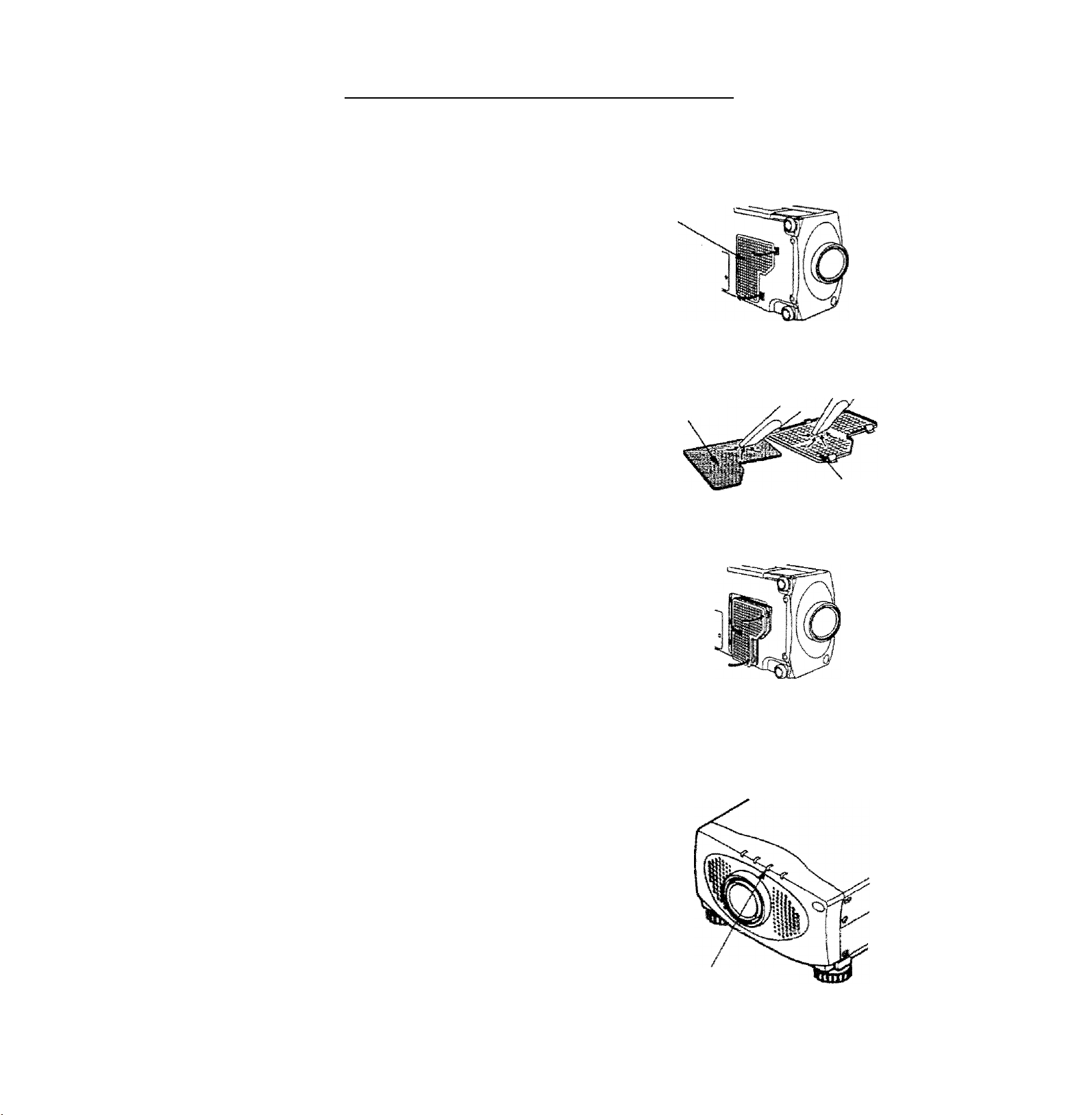
AIR FILTER CARE AND CLEANING
uabte air filter prevents dust from accumulating on the surface of the projection lens and projection mirror.
=i air filter become dogged with dust particles, It will reduce the cooling fan’s effectiveness and may result in
b,
CT
uid jjyjid up and reduce the life of the projector.
’ . air filter, follow the cleaning procedures below:
TO clean s« pQWER ON/OFF button OFF.
2
Flemov
3. air filter with a vacuum cleaner.
¿ _ .ug air filter. Make sure that air iter cover is fulfy inserted.
Replace i.i
po not clean with water. Doing so may damage the air filter.
Do not operate the projector with air filter removed.
A
BECOMWEN0ATION
cover.
n enjoy picture image, use the projector m
WF CLEAN ENVIRONMENT. USAGE IN THE CLEAN
¡MVIBONMENT IS RECOMMENDED.
yged under the dusty or smoky conditions, dust may
^^i-umulate on the liquid crystal panel and lens inside it, and may
rsultantly bo projected on the screen together with the picture,
vvnen the above symptoms are noticed contact the place where your
r^utno'n^ed dealer or service station for the cleaning.
___________
AIR FILTER
COVER
I
AIR FILTER
AIR FILTER
COVER
)
TEMPERATURE WARNING INDICATOR
C
me TE?«^PERATURE WARNING INDICATOR flashes red when the interna!
■emoerature of the projector exceeds the norma! temperature.
Possible causes for the temperature warning may be;
■ Ventilation slots of the projector are blocked, in such an event, reposition the
projector so that ventilation slots are not obstructed.
2 A)f filter is dogged with dust particles. Remove dust from the air filter by
ioitomng instructions in the Air Fitter Care and Cleaning section above.
3 H lernoerature warning indicator remains on after performing the checks
iisted aDove, cooling fan/iniernal circuits may be malfunctioning. Request
service from an authorized dealer or service station.
-47-
TEMPERATURE
WARNING
INDICATOR
Page 48

c
If the lamp fails to come on and the lamp monitor on the projector Ight is orange, you ¡musí replace the buib.
For continued safety, replace with a lamp assembly of the same type.
LAMP REPLACEMENT
A
Follow these steps to replace the (amp assembly.
1
. Turn off the projector and allow the projector to cool thoroughly,
1
2. Disconnect the AC cord from the projector.
13. Remove screw with a screwdriver and disconnect the lamp cover.
4. Remove 2 screws with a screwdnver and pull out the lamp assembly by
grasping the handle.
5. Replace the lamp assembly.
6. Tighten 3 screws to secure the tamp cover to the lamp assembly.
7. Connect the detachable AC cord to the projector.
• Allow the projector to coof for at least 45 minutes before you open the lamp cover. The
inside of the projector can become very hot.
• Do not drop the lamp module or touch the glass bulb ! The glass can shatter and cause
injury.
LAMP REPLACEMENT
INDICATOR
LAMP
8. Reset the lamp replacement monitor timer. (See "LAMP AGE" section on page 46.)
NOTE; Do not reset the LAMP REPLACEMENT MONITOR TIMER, except after the lamp is replaced.
-48 —
Page 49

coi!ow these steps to clean the pivfecSon lens-
ipply a non-abrasfve camera lens cisan^r fn » ^ .
..
-Avoid using an excessive amount of ciTnef ^ cteaning ciolh.
Abrasive cleaners, solvents or other hamh ,
2. LigMiy wipe the cleaning cloth over the Jens ” scratch the Jens
-donl intend to use the ptqector immediately, repiaee
3. rt you ’
ggfore caing your dealer or.sefvice station lor assistance, follow these steps, to make sure everything is properly
the lens cover.
y°u have connected the projector to your equipment as described in section ” CONNECTING THE
PROJECTOR” on pages 10- 17.
Check cable connections. Verity that all computer, video and power cords are property connected.
3 Verity that power is switched on.
4 If the projector stl does not display an image, restart the computer.
if iris image still does not display, unplug the projector from the computer and check the computer monitor's display.
^ Tne'probiem may be wîh your graphics controller rather than with the projector. (When you reconriect the projector,
remember to turn the computer and monitor off before you power up the projector. Power the equipment back up in
this order: Projector, monitor, computers
5
}f the problem still exists, check the following chart.
: TryîîHéiss Soïiîtiôns:
No power
Problem:
• Plug the projector into an AC outlet.
• Turn the MAIN ON/OFF button to OM.
• Press the LAIVIP POWER ON/OFF switch to ON.
• Be sure the READY INDICATOR light is ON.
• Wait one minute after the projector is turned OFF befo-'-e
turning the projector back on.
NOTE: After pressing the LAMP POWER ON/OFF button to
OFF . The projector functions as indicated.
1. The LAMP POWER indicator wit! fight and the READY
indicator will turn off.
2. After one minute, the READY indicator will light green again
and ih© projector may be turned on by pressing the LAMP
POWER ON/OFF button.
• Check temperature warning indicator, if the Indicator flashes
red. the projector cannot be turned on.
(See “USING THE PROJECTOR” section on page 27).
• Check the projection lamp.
i
image is out of focus
• Adjust the focus.
• Make sure the projeciion screen Is a! least 3.6 feet (1.1 m>
from the projector.
the projection tens to see if it .needs cioani.ng.
NOTE: Moving the projector from a cool temperature location
to a warm temperature location may result in moisture
condensation on the lens. In such an event, leave the
projector OFF and wait until condensation disappears.
■ 49-
Page 50

•Problem: "'-H
Solutions.,
PICurolslVRRovorsod. .
: - “'I
Picture is T^ inv^rted.
Some displays are not seen“^-—
during the operation.
No sound.“"- '77'-' • -'y'
Remote control unit-doesn’t- *’fi
work. '
Wireless mouse function does
not work.
-fir;
. ' .-i ■ ■ ¡2,
r Check Geiiln^Rear feature,
(See "OTHER FUNCTION SETTING” section on pages 44 ~
; Check Ceiling feature.
(See "OTHER FUNCTION SETTING” section on pages 44 ~ 45
Check Display feature.
' (See "OTHER FUNCTION SETTING” section an pages 44 ^ 45
# Check audio cable connection from audio input source.
•Adjust audio source.
• Press the VOLUME (-f) button.
♦ Press the MUTE button.
■ • Check the batteries.
• Make sure nothing is blocking between the remote contrt
sensor and remote control unit.
• Make sure you are not too far from the projector when using th
remote controi unit. {Maximum operate range 16.4 feet (5 m)|-.
• Check the cable connection between the projector and th*
computer.
• Check the mouse setting on your computer. |
• Turn on the projector before you turn on thé computer. *
Where to Get Help:
If you siil! need help after checking the table above, you
should call your dealer’s technical support line and
explain your problem.
If your dealer cannot solve your problem, please call
Proxima's customer service. The number is;
USA or Canada
Phone (800) 447-7694
FAX (619)457-8542
Rest of Word
Europe
Support
Phone (619) 457-5500
Phone +31 -43-358-5200
FAX +31-43-358-5201
http://www.proxima.com
In the event that your unit is determined to be
defective, you’ll be issued a Return Authorization
Number.
After youVe received this number, send the unit, a
copy of your sales receipt, and a description of the
problem, freight prepaid, to Proxima. Clearly note
the Return Authorization Number on the outside of
the shipping box.
. c;n.
 Loading...